Embed Size (px)
Citation preview

Model RS41
04-09-18 Part# P15867-1
Cancer and Reproductive Harmwww.P65Warnings.ca.gov
WARNING
BROADCAST SPREADER
Owner’s Manual
1
23
4
5
6
78
9
19
10
1112
13
14
15
16
17
18
20
21
22
23
24
13
KEY DESCRIPTION PART # KEY DESCRIPTION PART #
1 Hopper Ass’y-includes #2&3 P14508-1SH 13 Drive & Free Turning Wheel (2) P14939-12 Rate Cam & Chute Assembly P14455-1 14 Handle Braces (2) P136131-033 Shutoff Plate P14454-1 15 Handle Tube P145132-034 Impeller Assembly P15849 16 T-Handle Assembly P13634-25 Frame Assembly P15837 17 Control Knob Spring P144626 Legs (2) P136191-03 18 Control Knob & Wire Ass’y. P1461517 Axle P15842 19 Wire Retaining Clip P13643-18 Axle Collar P14634 20 Gear Cover Assembly P136239 Axle Bushings (2) P14951 21 Fastener Package P1588010 Impeller Shaft Bearing P15833 22 Hopper Cover P1520911 Axle Gear P13625-1 23 Handle Grip (2) P1526412 Agitator 33117 24 Hopper Label P16235
400 Oakwood RoadLake Zurich, IL 60047
Phone 847 540-8400 / Fax 847-540-8416www.shindaiwa-usa.com
PARTS LIST FOR shindaiwa RS41
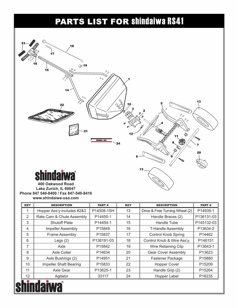
1. Remove the spreader and components from the carton. Turn spreader upside down. Insert (2) 1/4-20 x 1 1/2” hex bolts through the flattened end of handle brace, frame and leg as shown. Install hex nuts but do not tighten. Repeat on opposite side. Make sure braces are parallel and tighten all nuts
2. Slide wheels onto axle with the longer portion of the wheel facing the frame. The wheels are identical to ease assembly. Secure free turning wheel with (1) 1/8 x 1” cotter pin and (1) 5/32 x 2” cotter pin on the drive wheel.
VIEWED FROM REAR OF SPREADER
3. Turn spreader upright and install handle tube between braces with the identification “Dot” toward the hopper assembly. Secure with (2) 1/4-20 x 2” hex bolts and nuts. Tighten handle brace nuts installed in step 1.
NOTE: When installing the bolts, slide your finder inside the end of the handle shaft and press the control wire to the top of the handle shaft and hold, then install the bolts and release the control wire.
Drive Wheel
5/32 x 2” Cotter Pin
1/4-20 x 1 1/2” Hex Bolts
1/4-20 Hex Nuts
Handle Brace
Frame
1/4-20 X 2”Hex Bolts
Leg
1/8 x 1” Cotter Pin
Free Wheel
HandleTube
1/4-20 Hex Nuts
Identification “Dot”
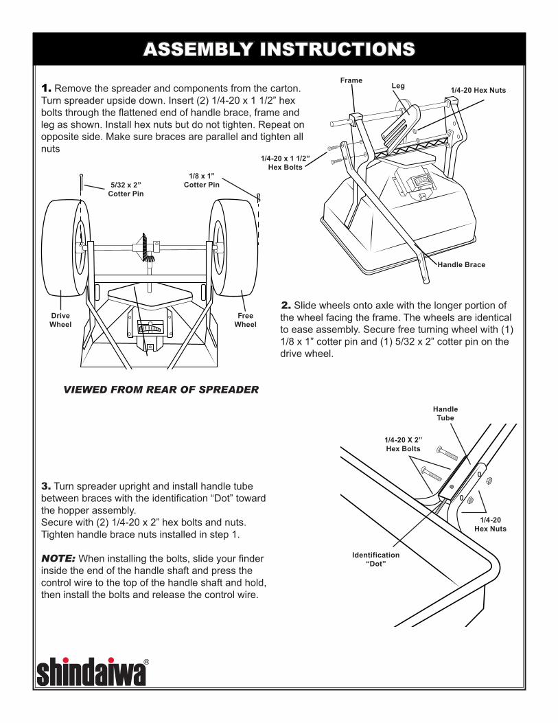
ASSEMBLY INSTRUCTIONS
4. Feed control knob/wire through the T-handle until spring touches the round hole. CAUTION: Do Not Compress Spring At This Time. Feed wire through the square handle tube. Be sure wire passes above the bolts in the handle brace. Secure T-handle to the tube with (1) 1/4-20 x 2” hex bolt. (2) washers, and (1) hex nut in the bottom hole, and (1) 1/4-20 x 2 1/4” hex bolt, (2) washers, and (1) hex nut in the top hole as shown. Remove caution label and push the thumb release toward the center and push down knob and shut-off spring until knob latches.
5. Slide wire retaining clip onto wire as shown. Insert wire through hole shut-off plate. Slide wire retaining clip over shut-off plate and wire until the clip locks into place.
6. Install gear cover assembly over gears and secure with (2) #6-32 screws. The RS41 spreader should now be completely assembled and ready for use. Slide handle grips onto handle. Soapy water will ease installation. (Do not use petroleum based products.)
CAUTION: ONCE KNOB IS LATCHED, DO NOT MOVE THUMB RELEASE UNTIL
YOU HAVE COMPLETED STEP #5.
Wire Clip
Shut-OffWire
Install Handle Grips
#6-32 Screw (2x)
Remove CautionLabel Spring
ThumbRelease
1/4-20 Hex Nut &
Washer
1/4-20 x 2 1/4” Bolt & Washer
1/4-20 x 2” Bolt & Washer
ASSEMBLY INSTRUCTIONS, continued
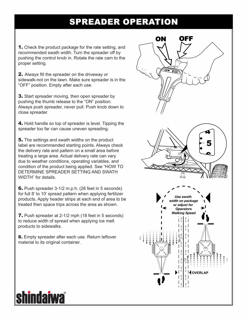
1. Check the product package for the rate setting, and recommended swath width. Turn the spreader off by pushing the control knob in. Rotate the rate cam to the proper setting.
2. Always fill the spreader on the driveway or sidewalk-not on the lawn. Make sure spreader is in the “OFF” position. Empty after each use.
3. Start spreader moving, then open spreader by pushing the thumb release to the “ON” position. Always push spreader, never pull. Push knob down to close spreader.
4. Hold handle so top of spreader is level. Tipping the spreader too far can cause uneven spreading.
5. The settings and swath widths on the product label are recommended starting points. Always check the delivery rate and pattern on a small area before treating a large area. Actual delivery rate can vary due to weather conditions, operating variables, and condition of the product being applied. See “HOW TO DETERMINE SPREADER SETTING AND SWATH WIDTH” for details.
6. Push spreader 3-1/2 m.p.h. (26 feet in 5 seconds) for full 8’ to 10’ spread pattern when applying fertilizer products. Apply header strips at each end of area to be treated then space trips across the area as shown.
7. Push spreader at 2-1/2 mph (18 feet in 5 seconds) to reduce width of spread when applying ice melt products to sidewalks.
8. Empty spreader after each use. Return leftover material to its original container.
OFFON
Use swath width on package
or adjust for Operators
Walking Speed
OVERLAP
SPREADER OPERATION
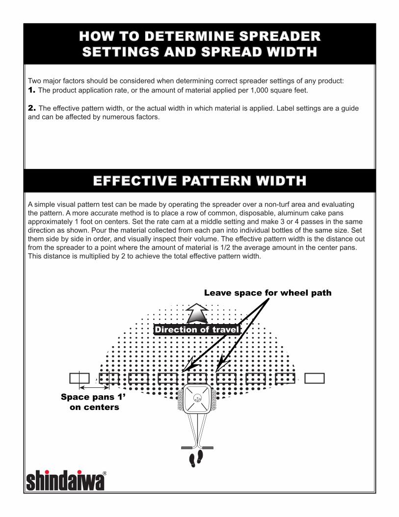
Two major factors should be considered when determining correct spreader settings of any product:1. The product application rate, or the amount of material applied per 1,000 square feet. 2. The effective pattern width, or the actual width in which material is applied. Label settings are a guide and can be affected by numerous factors.
A simple visual pattern test can be made by operating the spreader over a non-turf area and evaluating the pattern. A more accurate method is to place a row of common, disposable, aluminum cake pans approximately 1 foot on centers. Set the rate cam at a middle setting and make 3 or 4 passes in the same direction as shown. Pour the material collected from each pan into individual bottles of the same size. Set them side by side in order, and visually inspect their volume. The effective pattern width is the distance out from the spreader to a point where the amount of material is 1/2 the average amount in the center pans. This distance is multiplied by 2 to achieve the total effective pattern width.
Leave space for wheel path
Direction of travel
Space pans 1’ on centers
HOW TO DETERMINE SPREADERSETTINGS AND SPREAD WIDTH
EFFECTIVE PATTERN WIDTH
FERTILIZERBAG RATE
Pounds of fertilizer used per 1,000 sq. ft. of coverage
APPROXIMATESETTING
SPREADWIDTH
(IN FEET)
Large, heavy particles
51015
3 1/2 4
4 1/2
888
Medium, mixed particles
51015
2 1/23 1/2
4
888
Small particles(Nitrogen)
123
22 1/2
3
888
Mixed size particlesSome fines
51015
33 1/2
4
666
Lightweight particles5
1015
22 1/2
3
4To6
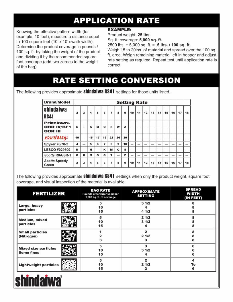
The following provides approximate shindaiwa RS41 settings for those units listed.
EXAMPLE: Product weight: 25 lbs.Sq. ft. coverage: 5,000 sq. ft.2500 lbs. ÷ 5,000 sq. ft. = .5 lbs. / 100 sq. ft.Weigh 15 to 20lbs. of material and spread over the 100 sq. ft. area. Weigh remaining material left in hopper and adjust rate setting as required. Repeat test until application rate is correct.
Knowing the effective pattern width (for example, 10 feet), measure a distance equal to 100 square feet (10’ x 10’ swath width). Determine the product coverage in pounds / 100 sq. ft. by taking the weight of the product and dividing it by the recommended square foot coverage (add two zeroes to the weight of the bag).
The following provides approximate shindaiwa RS41 settings when only the product weight, square foot coverage, and visual inspection of the material is available.
Brand/Model Setting Rateshindaiwa RS41
2 3 4 5 6 7 8 9 10 11 12 13 14 15 16 17 18
Prizelawn® CBR IV/BF1 CBR III
E I K M O R W Z — — — — — — — — —
10 — 15 17 19 22 26 30 — — — — — — — — —
Spyker 76/78-2 4 — 5 6 7 8 9 10 — — — — — — — — —
LESCO #029600 D — H — K M Q S — — — — — — — — —
Scotts R8A/SR-1 G K M O Q T — Z — — — — — — — — —
Scotts Speedy Green 2 3 4 5 6 7 8 9 10 11 12 13 14 15 16 17 18
APPLICATION RATE
RATE SETTING CONVERSION
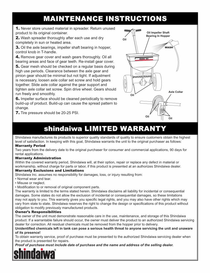
1. Never store unused material in spreader. Return unused product to its original container.2. Wash spreader thoroughly after each use and dry completely in sun or heated area.3. Oil the axle bearings, impeller shaft bearing in hopper, control knob in T-handle.4. Remove gear cover and wash gears thoroughly. Oil all bearing areas and face of gear teeth. Re-install gear cover.5. Gear mesh should be checked on a regular basis during high use periods. Clearance between the axle gear and pinion gear should be minimal but not tight. If adjustment is necessary, loosen axle collar set screw and hold gears together. Slide axle collar against the gear support and tighten axle collar set screw. Spin drive wheel. Gears should run freely and smoothly.6. Impeller surface should be cleaned periodically to remove build-up of product. Build-up can cause the spread pattern to change.7. Tire pressure should be 20-25 PSI.
Oil Impeller Shaft Bearing In Hopper
Oil
Axle Collar
Shindaiwa manufactures its products to superior quality standards of quality to ensure customers obtain the highest level of satisfaction. In keeping with this goal, Shindaiwa warrants the unit to the original purchaser as follows:Warranty PeriodTwo years from the delivery date to the original purchaser for consumer and commercial applications, 90 days for rental applications.Warranty AdministrationWithin the covered warranty period, Shindaiwa will, at their option, repair or replace any defect in material or workmanship, without charge for parts or labor, if this product is presented at an authorizes Shindaiwa dealer.Warranty Exclusions and LimitationsShindaiwa Inc. assumes no responsibility for damages, loss, or injury resulting from:• Normal wear and tear.• Misuse or neglect.• Modification to or removal of original component parts.The warranty is limited to the terms stated herein. Shindaiwa disclaims all liability for incidental or consequential damages. Some states do not allow the exclusion of incidental or consequential damages, so these limitations may not apply to you. This warranty gives you specific legal rights, and you may also have other rights which may vary from state to state. Shindaiwa reserves the right to change the design or specifications of this product without obligation to modify previously manufactured products.Owner’s ResponsibilitiesThe owner of the unit must demonstrate reasonable care in the use, maintenance, and storage of this Shindaiwa product. If a warrantable failure should occur, the owner must deliver the product to an authorized Shindaiwa servicing dealer for correction. All residual chemicals must be removed from the hopper prior to delivery.Unidentified chemicals left in tank can pose a serious health threat to anyone servicing the unit and unaware of its presence!To obtain warranty service, proof of purchase must be presented to the authorized Shindaiwa servicing dealer when the product is presented for repairs.Proof of purchase must include date of purchase and the name and address of the selling dealer.
WASH
Oil
Oil
Oil
shindaiwa LIMITED WARRANTY
MAINTENANCE INSTRUCTIONS

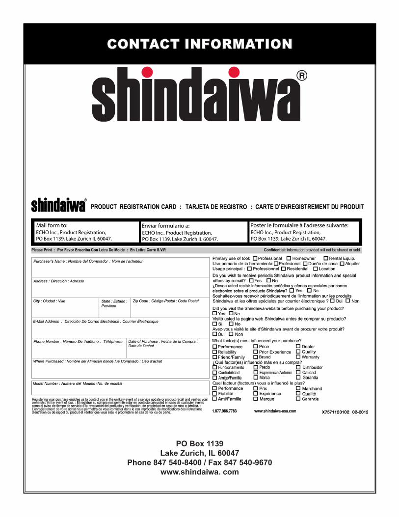
CONTACT INFORMATION
PO Box 1139Lake Zurich, IL 60047
Phone 847 540-8400 / Fax 847 540-9670www.shindaiwa. com