Embed Size (px)
Citation preview
1
BROADBAND TRANSMISSION LOSS PERFORMANCE OF A HEMISPHERICAL END-CHAMBER MUFFLER WITH SINGLE END-
INLET AND SINGLE/DOUBLE END-OUTLET
Akhilesh Mimani
School of Mechanical Engineering The University of Adelaide, Adelaide SA 5005, Australia
Email: [email protected]
Abstract
The axially short circular/elliptical cylindrical chamber is often used as a flow-reversing or straight-flow end-chamber in a multi-pass perforated duct muffler, a typical component of a modern-day automotive exhaust system. However, due to its small expansion volume, such short end chambers yield low acoustic attenuation (expressed in terms of Transmission Loss (TL)) in the low-frequency range, induce a large back pressure and increasing the chamber length results in the occurrence of a trough (due to the first axial mode) at a lower frequency that deteriorates the TL performance. In view of these limitations, the use of a different geometry, namely, a rigid-wall hemispherical cavity as a flow-reversal end-chamber muffler is investigated for potentially enhancing the TL performance over a wider frequency range, especially at low frequencies. To this end, this paper analyses the TL performance of a hemispherical end-chamber muffler having a single end-inlet and single/double end-outlet by means of a 3-D semi-analytical formulation based on the modal expansion of the acoustic field and the Green’s function approach. The 3-D acoustic field inside the rigid-wall hemispherical end-chamber is expressed in terms of the orthogonal modal functions. The hemispherical end-chamber muffler system is characterised using the uniform piston-driven model in terms of the impedance [Z] matrix parameters obtained by computing the average of the 3-D Green’s function over the surface area of the ports which are modelled as rigid pistons. The TL graphs computed by using the 3-D semi-analytical formulation are found to be in an excellent agreement with that obtained from the 3-D FEA, thereby validating the technique used here. Furthermore, the 3-D modal expansion method enables one to take into account, the relative polar angular location between the ports and also determine their optimal radial offset distance (corresponding to appropriate pressure nodes on the end face) to obtain a broadband TL performance. A comparison of the TL performance of the optimised hemispherical end-chamber muffler with that of an equivalent circular end-chamber having an equal volume demonstrates a significantly higher frequency range over which a broadband attenuation is obtained by using the hemispherical cavity. Similarly, a comparison with the TL graph of an equivalent axially short circular end-chamber indicates that the former exhibits higher attenuation in the low-frequency range.
1. Introduction
The circular and elliptical cylindrical flow-reversal and straight-flow expansion chamber are often used as end-chamber in a multi-pass perforated duct muffler [1] which is a typical component of a modern-day automotive exhaust system. Due to constraints on overall size of the multi-pass perforated muffler system, axially short end-chambers are used [1-3]. The 1-D transverse plane wave approach [2, 3] is used to analyse the Transmission Loss (TL) performance of such short elliptical (circular) chamber by considering wave propagation along its major-axis (or along a diameter) wherein the end inlet/outlet ports are located on the major-axis (or along the same diameter). It is noted that Selamet and Ji [4] had earlier presented an equivalent 1-D diametral plane wave approach to analyse short
2
circular chambers. On the basis of the 1-D transverse plane wave approach, it was found that a configuration having an end-centred inlet/outlet and end-offset outlet/inlet located on the same/opposite end face exhibited a peak in the TL spectrum at the resonance frequency of the (1, 1) even mode and (1, 0) mode of the elliptical and circular chambers, respectively, resulting in broadband attenuation up to the cut-on frequency of next higher-order transverse mode [1].
Mimani [5] used a 3-D semi-analytical formulation based on the modal expansion and the Green’s function method to obtain optimal location of the end-inlet and end-outlet ports for axially short elliptical/circular end-chambers which yield a broadband attenuation performance of over a much wider frequency range that is tabulated in Munjal [1]. In particular, for an elliptical chamber, it was shown that one of the end-offset ports should be located on the major-axis on the pressure node of the (2, 1) even mode whilst the other end port should be located on the minor-axis on the pressure node of the (0, 2) even mode. For obtaining a broadband TL performance for a circular chamber, an end-centred port and end-offset port that is located on the pressure node of the (0, 1) radial mode is recommended. However, it is observed that regardless of the use of 1-D or 3-D approach for obtaining broadband TL performance, such short chambers yield low attenuation due to its small expansion volume. Furthermore, an increase in the chamber length L whilst using optimal end port location does not necessarily improve the TL performance because the possible occurrence of a trough due to the first axial mode [6, 7] at lower frequency leads to breakdown of broadband attenuation characteristics.
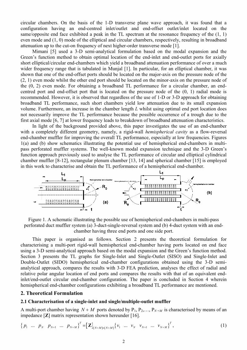
In light of the background provided above, this paper investigates the use of an end-chamber with a completely different geometry, namely, a rigid-wall hemispherical cavity as a flow-reversal end-chamber muffler for improving the overall TL performance, especially at low frequencies. Figures 1(a) and (b) show schematics illustrating the potential use of hemispherical end-chambers in multi-pass perforated muffler systems. The well-known modal expansion technique and the 3-D Green’s function approach previously used to analyse the TL performance of circular and elliptical cylindrical chamber muffler [8-12], rectangular plenum chamber [13, 14] and spherical chamber [15] is employed in this work to characterise and obtain the TL performance of a hemispherical end-chamber.
Figure 1. A schematic illustrating the possible use of hemispherical end-chambers in multi-pass perforated duct muffler system (a) 3-duct-single-reversal system and (b) 4-duct system with an end-
chamber having three end ports and one side port.
This paper is organised as follows. Section 2 presents the theoretical formulation for characterising a multi-port rigid-wall hemispherical end-chamber having ports located on end face using a 3-D semi-analytical approach based on the modal expansion and the Green’s function method. Section 3 presents the TL graphs for Single-Inlet and Single-Outlet (SISO) and Single-Inlet and Double-Outlet (SIDO) hemispherical end-chamber configurations obtained using the 3-D semi-analytical approach, compares the results with 3-D FEA prediction, analyses the effect of radial and relative polar angular location of end ports and compares the results with that of an equivalent end-inlet/end-outlet circular end-chamber configuration. The paper is concluded in Section 4 wherein hemispherical end-chamber configurations exhibiting a broadband TL performance are mentioned.
2. Theoretical Formulation
2.1 Characterisation of a single-inlet and single/multiple-outlet muffler
A multi-port chamber having N M ports denoted by P1, P2,…, PN +M is characterised by means of an impedance [Z] matrix representation shown hereunder [16].
1 1 1 1... ... ... ... ,T TN N N M N N N MN M N Mp p p p v v v v
Z (1)
3
1 1 111 1
1 1
1 1 1 1 1 1
1 1
.
N N MN
N NN N N N N M
N M N MN N N N N N N M
N M N M N N M N N M N M
Z ZZ Z
Z Z Z Z
Z Z Z Z
Z Z Z Z
Z
(2)
The acoustic pressure (Pa) and mass-velocity 3kg m at the ports P1, P2,…, PN+M of the N+M
port system are denoted by 1 1... ...N N N Mp p p p and 1 1... ... ,N N N Mv v v v respectively. It is noted that direction of the mass-velocity is considered positive looking into the system and a harmonic time-dependence is assumed so that ωj t
i ip p e and ω ,j ti iv v e i =1, 2,…, N+M.
Furthermore, 1,j t denotes time (in seconds), is the excitation angular frequency 1radian s given by 2 ,f where f is the frequency in Hz. In the ensuing subsection, a multi-port hemispherical end-chamber having N M end ports is characterised using the uniform piston-driven model via the 3-D Green’s function approach in terms of the [Z] matrix representation. It is noted that walls of the hemispherical end-chamber are considered rigid (with no absorptive linings), therefore, a conservative system is being considered [3]. Furthermore, a stationary medium, i.e., a zero mean flow is assumed implying that the hemispherical expansion chamber satisfies the principle of acoustic reciprocity [17]. 2.2 Acoustic pressure field in a rigid-wall hemispherical chamber: Solution of the 3-D homogeneous Helmholtz equation The 3-D acoustic field in a hemispherical chamber (cavity) is obtained as the solution of the 3-D homogeneous Helmholtz equation in spherical polar co-ordinates given by [15, 18]
2
2 2 2 20 2 2 2
1 1 10, sin ,sin sin
k p rr r r
(3, 4)
where r is the radial co-ordinate, and are polar and azimuthal angular co-ordinates, respectively,
0 0k c is the excitation wavenumber and 0c denotes the sound speed. The separation of acoustic pressure field ΦΘ,, rRrp yields the following ordinary differential equations [18]
22
2
d Φ Φ 0,d
2
22
1 d Θsin Θ 0sin d sin
and 2 2 2 2
0d d 0,d d
Rr k r Rr r
(5-7)
governing wave propagation along the azimuthal, polar angular and radial directions, respectively. In Eqs. (5-7), and are separation constants where 2 1 . It is noted that the domain given by
00, 0, 0, r R spans the rigid-wall hemispherical chamber where 0R denotes the radius of the hemispherical chamber. The acoustic pressure field must satisfy the rigid-wall boundary condition along the azimuthal direction [18], i.e.,
0 0 0 0 0 0 0 0
Φ Φ1 1 0 0,sin sin
j p j puk ρ c r k ρ c r
(8, 9)
where u is the acoustic velocity component along the azimuthal direction and 0ρ is the ambient
density. Substituting the general solution of Eq. (5) given by 1 2Φ = cos sinC C in Eqs. (8)
and (9) yields 0, 1, 2,...m and 1Φ = cos ,C m where 1C and 2C are arbitrary constants.
4
Furthermore, since the range of polar angle 0, , i.e., it includes both poles, it is required to take n = 0, 1, 2,…, (positive integer values) in Eq. (6), which implies that its complete solution is given by
3 4Θ cos cos , .m mn nC P C Q m n (10)
where 3C and 4C are arbitrary constants, mnP and m
nQ are the Associated Legendre functions of
the first and second kind, respectively, of degree n and order m, see Refs. [18, 19]. Since, cosmnQ
is singular at the poles, it does not feature in the polar angular solution and Eq. (10) then simplifies as 3Θ cos .m
nC P The solution of spherical wave equation given by Eq. (7) is given by
5 0 6 0= ,n nR r C j k r C n k r (11)
where 5C and 6C are arbitrary constants, nj and nn are spherical Bessel and Neumann
functions, respectively, of order n. Since nn is singular at the origin that is part of the hemispherical domain, it does not feature in the radial solution [18, 19] and Eq. (11) then simplifies as 5 0= .nR r C j k r Rigid-wall boundary condition is imposed along the radial direction by setting the
derivative of spherical Bessel function to zero at the hemispherical chamber surface, i.e.,
0
0
0n
r R
j k rr
yielding the non-dimensional resonance frequencies nl given by
.,...2 ,1 ,,....2 ,1 ,0 ,0121
dd 1 1
0
0
lnn
jnnjrkrkjRk nlnnln
Rrnl
nlnnlnl
(12)
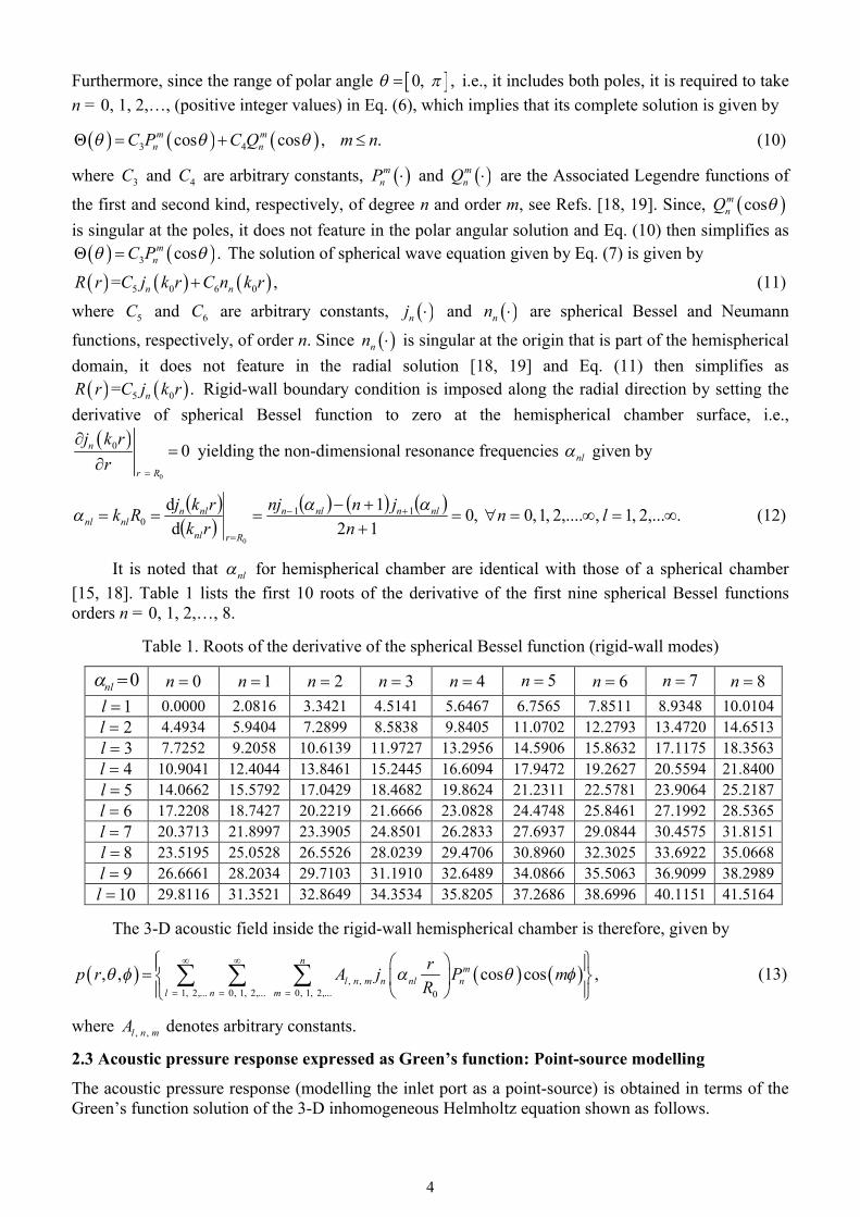
It is noted that nl for hemispherical chamber are identical with those of a spherical chamber [15, 18]. Table 1 lists the first 10 roots of the derivative of the first nine spherical Bessel functions orders n = 0, 1, 2,…, 8.
Table 1. Roots of the derivative of the spherical Bessel function (rigid-wall modes)
0nl 0n 1n 2n 3n 4n 5n 6n 7n 8n 1l 0.0000 2.0816 3.3421 4.5141 5.6467 6.7565 7.8511 8.9348 10.0104 2l 4.4934 5.9404 7.2899 8.5838 9.8405 11.0702 12.2793 13.4720 14.6513 3l 7.7252 9.2058 10.6139 11.9727 13.2956 14.5906 15.8632 17.1175 18.3563 4l 10.9041 12.4044 13.8461 15.2445 16.6094 17.9472 19.2627 20.5594 21.8400 5l 14.0662 15.5792 17.0429 18.4682 19.8624 21.2311 22.5781 23.9064 25.2187 6l 17.2208 18.7427 20.2219 21.6666 23.0828 24.4748 25.8461 27.1992 28.5365 7l 20.3713 21.8997 23.3905 24.8501 26.2833 27.6937 29.0844 30.4575 31.8151 8l 23.5195 25.0528 26.5526 28.0239 29.4706 30.8960 32.3025 33.6922 35.0668 9l 26.6661 28.2034 29.7103 31.1910 32.6489 34.0866 35.5063 36.9099 38.2989
10l 29.8116 31.3521 32.8649 34.3534 35.8205 37.2686 38.6996 40.1151 41.5164 The 3-D acoustic field inside the rigid-wall hemispherical chamber is therefore, given by
, , 1, 2,... 0, 1, 2,... 0, 1, 2,... 0
, , cos cos ,n
ml n m n nl n
l n m
rp r A j P mR
(13)
where , , l n mA denotes arbitrary constants.
2.3 Acoustic pressure response expressed as Green’s function: Point-source modelling
The acoustic pressure response (modelling the inlet port as a point-source) is obtained in terms of the Green’s function solution of the 3-D inhomogeneous Helmholtz equation shown as follows.
5
0 0 0 0
0 00 0
2 21,2,... 0,1,2... 0,1,2...0 , ,
, , , , , , , ,
cos cos cos cos,
R R R S S S R R R S S S
m mR Sn nl n nl n R n S R Sn
l n mnl l n m
p r r G r rQ Q
r rj j P P m mR R
jk ck k N
(14)
where 0Q is the volume flow-rate 3 1m s due to point-source port, , ,S S Sr and , ,R R Rr are the co-ordinates of the centre of the source and receiver ports, respectively, whilst
02
2, ,
00
!2d ,2 1 !
r R
l n m n nlmr
n mrN r j rR n n m
(15)
denotes the integrals of the square of the product of a particular set of orthogonal modal functions defined over the hemispherical chamber volume, 1m for 0m and 2m for 0.m It is noted that the radial part of the integral in Eq. (15) is evaluated analytically as shown below.
02
2
00
23 20
2 2
d
1 1 2 1.
2 2 1 2 1 2 3 2 1 2 3
r R
n nlr
n nln nl n nl n nl
rr j rR
j n n n n nR nj j jn n n n n
(16)
The Green’s function for a rigid-wall hemispherical obtained in Eq. (14) is identical with that of a rigid-wall spherical chamber [15] except for the absence of sin m term in the case of hemispherical chamber. Consequently, unlike the spherical chamber, the 3-D acoustic pressure field inside a hemispherical chamber is not symmetric along the azimuthal direction; rather, in general, it depends on the azimuthal modal function cos .m
2.4 Acoustic pressure response due to an end port based on the uniform piston-driven model
The mathematically more accurate uniform piston-driven model (in comparison to the point-source model) is used to obtain the mutual-impedance EiEiZ and cross-impedance EjEiZ parameters for characterising the hemispherical chamber having an end-inlet and end-outlet(s) shown as follows.
(a) Source and Receiver end ports both co-incident
2
00
2 21,2,.. 0,1,2.. 0,1,2..0 , ,
1 cos cos d d
.i
mSn nl n S S S S
nSi i
iil n mi i
nl l n m
rm j P r rRp jk YZ
v S k k N
(17)
(b) Source and Receiver end ports centred at different locations on the end face
100
2 21,2,.. 0,1,2.. 0,1,2..0 , ,
Δ cos d d 1 cos
,i
mSn nl n S S S S
nSj i
jil n mi j
nl l n m
rj P r r mRp jk YZ
v S k k N
(18)
where 10
Δ cos cos d dj
mRn nl n R R R R R
S
rj P m r rR
(19)
The mathematical form of the integral of the Green’s function over the end ports in Eqs. (17-19)
6
as well as the effect of port location on the propagation/suppression of certain modes on the [Z] matrix parameters are discussed in Ref. [5].
2.5 Computation of TL performance An expression for TL performance of a Single-Inlet and Single/Multiple-Outlet (SISO/SIMO) system is obtained in terms of the scattering S matrix parameters. To this end, the relation between the scattering S matrix and the Z matrix is first presented [11, 15, 16].
1 11 1 1
1 1 2 .M M
S Z Y Ι Z Y I I Z Y Ι (20)
In Eq. (20), the number of inlet ports N = 1, I is the identity matrix and [Y] is a diagonal matrix
consisting of the characteristic impedances of the ports. It is assumed that the ports are acoustically compact, i.e., their diameter is much smaller compared to the shortest wavelength of interest (to automotive muffler designer) so that only planar waves propagate. Anechoic termination is imposed at M outlet ports following which the TL expression is obtained for a general SIMO system given by [16]
22 2
1 121 31inlet10 inlet outlet
outlet 1 2 3 1
1TL 10log , , ... .M
M
SS SE E EE Y Y Y Y
(21)
The TL expression for a SIDO system is obtained by setting M = 2 in Eq. (21) and for the case of a SISO system, the TL expression is given by [10, 11, 15, 16]
211 1 22 2 21 122
10 1021 1 2 2121
1 1TL 10log 10log .4
Z Y Z Y Z ZYY Y Y ZS
(22)
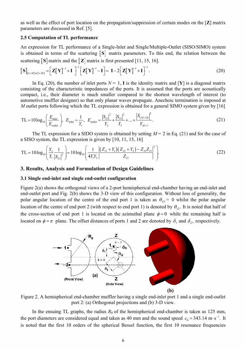
3. Results, Analysis and Formulation of Design Guidelines 3.1 Single end-inlet and single end-outlet configuration Figure 2(a) shows the orthogonal views of a 2-port hemispherical end-chamber having an end-inlet and end-outlet port and Fig. 2(b) shows the 3-D view of this configuration. Without loss of generality, the polar angular location of the centre of the end port 1 is taken as 1E = 0 whilst the polar angular location of the centre of end port 2 (with respect to end port 1) is denoted by 12. It is noted that half of the cross-section of end port 1 is located on the azimuthal plane 0 while the remaining half is located on plane. The offset distances of ports 1 and 2 are denoted by 1 and ,2 respectively.
Figure 2. A hemispherical end-chamber muffler having a single end-inlet port 1 and a single end-outlet
port 2: (a) Orthogonal projections and (b) 3-D view.
In the ensuing TL graphs, the radius R0 of the hemispherical end-chamber is taken as 125 mm, the port diameters are considered equal and taken as 40 mm and the sound speed 1
0 343.14 m s .c It is noted that the first 10 orders of the spherical Bessel function, the first 10 resonance frequencies
7
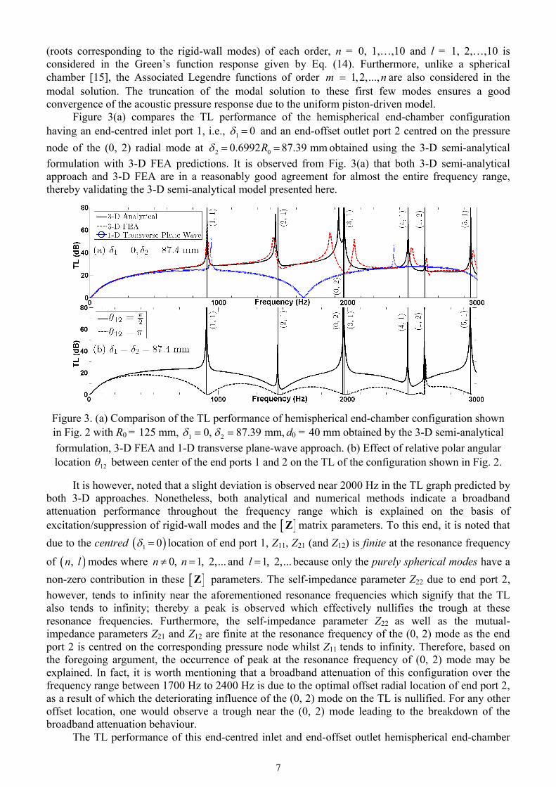
(roots corresponding to the rigid-wall modes) of each order, n = 0, 1,…,10 and l = 1, 2,…,10 is considered in the Green’s function response given by Eq. (14). Furthermore, unlike a spherical chamber [15], the Associated Legendre functions of order 1,2,...,m n are also considered in the modal solution. The truncation of the modal solution to these first few modes ensures a good convergence of the acoustic pressure response due to the uniform piston-driven model. Figure 3(a) compares the TL performance of the hemispherical end-chamber configuration having an end-centred inlet port 1, i.e., 1 0 and an end-offset outlet port 2 centred on the pressure node of the (0, 2) radial mode at 2 00.6992 87.39 mmR obtained using the 3-D semi-analytical formulation with 3-D FEA predictions. It is observed from Fig. 3(a) that both 3-D semi-analytical approach and 3-D FEA are in a reasonably good agreement for almost the entire frequency range, thereby validating the 3-D semi-analytical model presented here.
Figure 3. (a) Comparison of the TL performance of hemispherical end-chamber configuration shown in Fig. 2 with R0 = 125 mm, 1 0, 2 87.39 mm, d0 = 40 mm obtained by the 3-D semi-analytical formulation, 3-D FEA and 1-D transverse plane-wave approach. (b) Effect of relative polar angular location 12 between center of the end ports 1 and 2 on the TL of the configuration shown in Fig. 2.
It is however, noted that a slight deviation is observed near 2000 Hz in the TL graph predicted by both 3-D approaches. Nonetheless, both analytical and numerical methods indicate a broadband attenuation performance throughout the frequency range which is explained on the basis of excitation/suppression of rigid-wall modes and the Z matrix parameters. To this end, it is noted that due to the centred 1 0 location of end port 1, Z11, Z21 (and Z12) is finite at the resonance frequency
of , n l modes where 0, 1, 2,...n n and 1, 2,...l because only the purely spherical modes have a non-zero contribution in these Z parameters. The self-impedance parameter Z22 due to end port 2, however, tends to infinity near the aforementioned resonance frequencies which signify that the TL also tends to infinity; thereby a peak is observed which effectively nullifies the trough at these resonance frequencies. Furthermore, the self-impedance parameter Z22 as well as the mutual-impedance parameters Z21 and Z12 are finite at the resonance frequency of the (0, 2) mode as the end port 2 is centred on the corresponding pressure node whilst Z11 tends to infinity. Therefore, based on the foregoing argument, the occurrence of peak at the resonance frequency of (0, 2) mode may be explained. In fact, it is worth mentioning that a broadband attenuation of this configuration over the frequency range between 1700 Hz to 2400 Hz is due to the optimal offset radial location of end port 2, as a result of which the deteriorating influence of the (0, 2) mode on the TL is nullified. For any other offset location, one would observe a trough near the (0, 2) mode leading to the breakdown of the broadband attenuation behaviour. The TL performance of this end-centred inlet and end-offset outlet hemispherical end-chamber
8
configuration is also computed using the 1-D transverse plane wave analysis [1, 2] by considering wave propagation only along the z direction by modelling the chamber as a duct with gradually varying cross-section given by 2
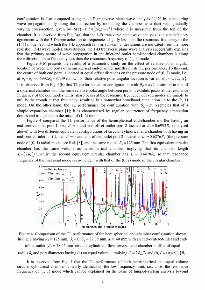
02 5.0)( zzRzS where z is measured from the top of the chamber. It is observed from Fig. 3(a) that the 1-D transverse plane wave analysis is in a satisfactory agreement with the 3-D approaches up to frequencies slightly less than the resonance frequency of the (1, 1) mode beyond which the 1-D approach fails as substantial deviations are indicated from the more realistic 3-D wave model. Nevertheless, the 1-D transverse plane wave analysis successfully explains that the primary nature of wave propagation in end-inlet/end-outlet hemispherical chambers is along the z direction up to frequency less than the resonance frequency of (1, 1) mode. Figure 3(b) presents the results of a parametric study on the effect of relative polar angular location between end ports of hemispherical end-chamber muffler on its TL performance. To this end, the centre of both end ports is located at equal offset distances on the pressure node of (0, 2) mode, i.e., at 1 2 00.6992 87.39 mmR whilst their relative polar angular location is varied: 12 2, . It is observed from Fig. 3(b) that TL performance for configuration with 12 2 is similar to that of a spherical chamber with the same relative polar angle between ports; it exhibits peaks at the resonance frequency of the odd modes whilst sharp peaks at the resonance frequency of even modes are unable to nullify the trough at that frequency, resulting in a somewhat broadband attenuation up to the (2, 1) mode. On the other hand, the TL performance for configuration with 12 resembles that of a simple expansion chamber [1]; it is characterised by regular occurrence of frequency attenuation domes and troughs up to the onset of (1, 2) mode. Figure 4 compares the TL performance of the hemispherical end-chamber muffler having an end-centred inlet port 1, i.e., 1 0 and end-offset outlet port 2 located at 2 00.6992R (analysed above) with two different equivalent configurations of circular cylindrical end-chamber both having an end-centred inlet port 1, i.e., 1 0 and end-offset outlet port 2 located at 2 00.6276R (the pressure node of (0, 1) radial mode, see Ref. [8]) and the same radius 0 125 mm.R The first equivalent circular chamber has the same volume as hemispherical chamber implying that its chamber length
02 3,L R whilst the second equivalent circular chamber has 0 0.4478L R so that resonance frequency of the first axial mode is co-incident with that of the (0, 2) mode of the circular chamber.
Figure 4. Comparison of the TL performance of the hemispherical end-chamber configuration shown in Fig. 2 having R0 = 125 mm, 1 0, 2 87.39 mm, d0 = 40 mm with an end-centered-inlet and end-
offset-outlet 2 78.45 mm circular cylindrical flow-reversal end-chamber muffler of equal
radius 0R and port diameters having (a) an equal volume, implying 02 3L R and (b) 0, 2 0.cL R
It is observed from Fig. 4 that the TL performance of both hemispherical and equal-volume circular cylindrical chamber is nearly identical up the low-frequency limit, i.e., up to the resonance frequency of (1, 1) mode which can be explained on the basis of lumped-system analysis beyond
9
which substantial deviation is observed. In particular, it is noted that while the hemispherical end-chamber exhibits a broadband attenuation performance (above 20 dB approximately) over the entire frequency range considered, the equal-volume circular chamber exhibits a trough at the resonance frequency of the first axial mode, i.e., at 0 2 2058.8 Hz,f c L leading to the breakdown of the broadband attenuation behaviour. On the other hand, the axially short circular chamber exhibits broadband attenuation behaviour over a much wider frequency range, precisely, up to the resonance frequency of (0, 3) radial mode; however, in comparison to the hemispherical chamber, it yields a relatively low attenuation in the low-frequency range due to its smaller volume. The aforementioned discussion therefore, indicates that a circular cylindrical end-chamber may be potentially replaced by a hemispherical end-chamber of equal radius with a view to achieve better attenuation performance.
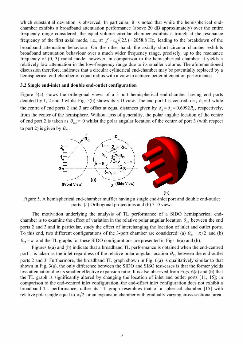
3.2 Single end-inlet and double end-outlet configuration Figure 5(a) shows the orthogonal views of a 3-port hemispherical end-chamber having end ports denoted by 1, 2 and 3 whilst Fig. 5(b) shows its 3-D view. The end port 1 is centred, i.e., 1 0 while the centre of end ports 2 and 3 are offset at equal distances given by 2 3 00.6992 ,R respectively, from the center of the hemisphere. Without loss of generality, the polar angular location of the centre of end port 2 is taken as 2E = 0 whilst the polar angular location of the centre of port 3 (with respect to port 2) is given by 23.
Figure 5. A hemispherical end-chamber muffler having a single end-inlet port and double end-outlet
ports: (a) Orthogonal projections and (b) 3-D view. The motivation underlying the analysis of TL performance of a SIDO hemispherical end-chamber is to examine the effect of variation in the relative polar angular location 23 between the end ports 2 and 3 and in particular, study the effect of interchanging the location of inlet and outlet ports. To this end, two different configurations of the 3-port chamber are considered: (a) 223 and (b)
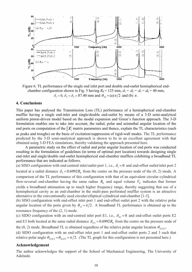
23 and the TL graphs for these SIDO configurations are presented in Figs. 6(a) and (b). Figures 6(a) and (b) indicate that a broadband TL performance is obtained when the end-centred port 1 is taken as the inlet regardless of the relative polar angular location 23 between the end-outlet ports 2 and 3. Furthermore, the broadband TL graph shown in Fig. 6(a) is qualitatively similar to that shown in Fig. 3(a), the only difference between the SIDO and SISO test-cases is that the former yields less attenuation due its smaller effective expansion ratio. It is also observed from Figs. 6(a) and (b) that the TL graph is significantly altered by changing the location of inlet and outlet ports [11, 15]; in comparison to the end-centred inlet configuration, the end-offset inlet configuration does not exhibit a broadband TL performance, rather its TL graph resembles that of a spherical chamber [15] with relative polar angle equal to 2 or an expansion chamber with gradually varying cross-sectional area.
10
Figure 6. TL performance of the single end inlet port and double end-outlet hemispherical end-chamber configuration shown in Fig. 5 having R0 = 125 mm, d1 = d2 = d3 = d0 = 40 mm,
,01 32 87.40 mm and 23 (a) 2 and (b) .
4. Conclusions
This paper has analysed the Transmission Loss (TL) performance of a hemispherical end-chamber muffler having a single end-inlet and single/double end-outlet by means of a 3-D semi-analytical uniform piston-driven model based on the modal expansion and Green’s function approach. The 3-D formulation enables one to take into account, the radial, polar and azimuthal angular location of the end ports on computation of the Z matrix parameters and thence, explain the TL characteristics (such as peaks and troughs) on the basis of excitation/suppression of rigid-wall modes. The TL performance predicted by the 3-D semi-analytical approach is shown to be in an excellent agreement with that obtained using 3-D FEA simulations, thereby validating the approach presented here.
A parametric study on the effect of radial and polar angular location of end ports was conducted resulting in the formulation of guidelines (in terms of optimal port location) towards designing single end-inlet and single/double end-outlet hemispherical end-chamber mufflers exhibiting a broadband TL performance that are indicated as follows. (a) SISO configuration with end-centred inlet/outlet port 1, i.e., 1 0 and end-offset outlet/inlet port 2 located at a radial distance 2 00.6992R from the centre on the pressure node of the (0, 2) mode. A comparison of the TL performance of this configuration with that of an equivalent circular cylindrical flow-reversal end-chamber having the same radius 0R and equal volume 0V indicates that former yields a broadband attenuation up to much higher frequency range, thereby suggesting that use of a hemispherical cavity as an end-chamber in the multi-pass perforated muffler system is an attractive alternative to the conventionally used circular/elliptical cylindrical end-chamber [1-3]. (b) SISO configuration with end-offset inlet port 1 and end-offset outlet port 2 with the relative polar angular location of the ports given by 12 2. A broadband TL performance is obtained up to the resonance frequency of the (2, 1) mode. (c) SIDO configuration with an end-centred inlet port E1, i.e., 1 0E and end-offset outlet ports E2 and E3 both located at the same radial distance 2 00.6992E R from the centre on the pressure node of the (0, 2) mode. Broadband TL is obtained regardless of the relative polar angular location 2 3.E E (d) SIDO configuration with an end-offset inlet port 1 and end-offset outlet ports 2 and 3 such that relative polar angle 1 2 1 3 2.E E E E (The TL graph for this configuration is not presented here.)
Acknowledgement
The author acknowledges the support of the School of Mechanical Engineering, The University of Adelaide.
11
References [1] Munjal, M. L. Acoustics of Ducts and Mufflers, Wiley, Chichester, 2014. [2] Mimani, A. and Munjal, M. L. “Transverse plane-wave analysis of short elliptical end-chamber
and expansion-chamber mufflers”, Journal of Sound and Vibration, 330, 1472-1489, (2011). [3] Mimani, A. and Munjal, M. L. “Transverse plane-wave analysis of short elliptical end-chamber
and expansion-chamber mufflers”, International Journal of Acoustics and Vibration, 15, 24-38, (2010).
[4] Selamet, A. and Ji, Z. L. “Diametral plane-wave analysis for short circular chambers with end offset inlet/outlet and side extended inlet/outlet”, Journal of Sound and Vibration, 214, 580-587, (1998).
[5] Mimani, A. “1-D and 3-D analysis of multi-port muffler configurations with emphasis on elliptical cylindrical chamber”, Ph. D. Thesis, Indian Institute of Science, Bangalore, March 2012.
[6] Mimani, A. and Munjal, M. L. “On the role of higher-order evanescent modes in end-offset inlet and end-centered outlet elliptical flow-reversal chamber mufflers”, International Journal of Acoustics and Vibration, 17, 139-154, (2012).
[7] Mimani, A. and Munjal, M. L. “Acoustic end-correction in a flow-reversal end chamber muffler: A semi-analytical approach”, Accepted for publication in the Journal of Computational Acoustics on the 1st October, 2015.
[8] Selamet, A. and Ji, Z. L. “Acoustic attenuation performance of circular flow-reversing chambers”, Journal of the Acoustical Society of America, 104, 2867-2877, (1998).
[9] Ih, J.-G. and Lee, B. H. “Theoretical prediction of the transmission loss for the circular reversing chamber mufflers”, Journal of Sound and Vibration, 112, 261-272, (1987).
[10] Mimani, A. and Munjal, M. L. “3-D acoustic analysis of elliptical chamber mufflers having an end-inlet and a side-outlet: An impedance matrix approach”, Wave Motion, 49, 271-295, (2012).
[11] Mimani, A. and Munjal, M. L. “Acoustical behavior of single inlet and multiple outlet elliptical cylindrical chamber muffler”, Noise Control Engineering Journal, 60, 605-626, (2012).
[12] Denia, F. D., Albelda, J., Fuenmayor, F. J. and Torregrosa, A. J. “Acoustic behaviour of elliptical chamber mufflers”, Journal of Sound and Vibration, 241, 401-421, (2001).
[13] Ih, J.-G. “The reactive attenuation of rectangular plenum chambers”, Journal of Sound and Vibration, 157, 93-122, (1992).
[14] Venkatesham, B., Tiwari, M. and Munjal, M. L. “Transmission loss analysis of rectangular expansion chamber with arbitrary location of inlet/outlet by means of Green’s function”, Journal of Sound and Vibration, 323, 1032-1044, (2009).
[15] Mimani, A. and Munjal, M. L. “3-D acoustic analysis of spherical chamber having single inlet and multiple outlet: An impedance matrix approach”, International Journal of Applied Mechanics, 3, 685-710, (2011).
[16] Mimani, A. and Munjal, M. L. “Acoustical analysis of a general network of multi-port elements - An impedance matrix approach”, International Journal of Acoustics and Vibration, 17, 23-46, (2012).
[17] Easwaran, V., Gupta, V. H. and Munjal, M. L. “Relationship between the impedance matrix and the transfer matrix with specific reference to symmetrical, reciprocal and conservative systems”, Journal of Sound and Vibration, 161, 515-525, (1993).
[18] Blackstock, D. T. Fundamentals of Physical Acoustics, Wiley, New York, 2000. [19] Arfken, G. B. and Weber, H. J. Mathematical Methods for Physicists, Academic Press, Elsevier,
London, 2005.