Embed Size (px)
Citation preview
ISBN-13:ISBN-10:
978-0-13-230057-50-13-230057-5
9 7 8 0 1 3 2 3 0 0 5 7 5
5 5 9 9 9Printed on recycled paper
Cover image: © Stock Illustration Source
BROADBAND NETWORKARCHITECTURESService providers are increasingly focused on delivering triple-play bundles that incorporate Internet, video, and VoIP services—as well as multi-play bundles containing even more advanced services. Broadband Network Architectures is the first comprehensive guide to designing, implementing, and managing the networks that make triple-play services possible.
Hellberg, Greene, and Boyes present their field-tested industry best practices and objectively evaluate the tradeoffs associated with key up-front architectural decisionsthat balance the complexities of bundled services and sophisticated traffic policies.Broadband Network Architectures not only documents what is possible on this rapidlychanging field of networking, but it also details how to divide Internet access into these more sophisticated services with specialized Quality of Service handling.
Coverage includes
• An in-depth introduction to next-generation triple-play services: components, integration, and business connectivity
• Triple-play backbone design: MPLS, Layer 3 VPNs, and Broadband Network Gateways (BNGs)/Broadband Remote Access Servers (B-RAS)
• Protocols and strategies for integrating BNGs into robust triple-play networks
• Triple-play access network design: DSLAM architectures, aggregation networks, transport, and Layer 2 tunneling
• VLAN-per-customer versus service-per-VLAN architectures: advantages and disadvantages
• PPP or DHCP: choosing the right access protocol
• Issues associated with operating in wholesale, unbundled environments
• IP addressing and subscriber session management
• Broadband network security, including Denial of Service attacks and VoIP privacy
• The future of wireless broadband: IMS, SIP, and non-SIP based fixed mobile convergence and wireless video
ABOUT THE AUTHORS
Chris Hellberg, Professional Services Consultant forJuniper Networks, specializes in B-RAS and routing andswitching. He has Cisco and Juniper design and operationalexperience with carriers in all parts of the globe.
Dylan Greene, a consultant with the Juniper NetworksProfessional Services group, has more than a decade oftechnical networking experience. His primary expertise isin designing and deploying IP and MPLS networks, with asubfocus on network security.
Truman Boyes, Professional Services Engineer forJuniper Networks, has spent more than a decade designingand implementing large-scale carrier networks.
www.prenhallprofessional.com
Chris Hellberg, Dylan Greene, and Truman Boyes
Broadband N
etwork A
rchitecturesHellbergGreene Boyes
Networking
$59.99 US / $74.99 CANADA
Designing and Deploying Triple-Play Services
BROADBANDNETWORK
ARCHITECTURES
BROADBANDNETWORK
ARCHITECTURES“This book will help guide the reader towards understanding and engineering future-proof broadband network architectures.”
—Gavin Young, Chief Architect, Cable & Wireless Access
The Radia Perlman Series in Computer Networking and Security
Designing and Deploying Triple-Play Services
IncludesFREE 45-DayOnline Edition
“Network professionals who are looking to deploy triple-playservice provider networks will find this book a useful tool.”
—Michael Newbery, IP Architect, TelstraClear Limited
“This book provides a wealth of information on current andfuture broadband architectures, services, and deployments.It will serve both experienced technical experts needing acomprehensive reference, as well as those needing a conciseexplanation of broadband access architectures and multi-play services.”
Sanjay Wadhwa, Product Line Manager, IP Edge Products,Juniper Networks
“This book is a thorough guide for anyone involved withtriple-play networks. Its multivendor approach and referencesto the latest standards from the DSL Forum and the IETFmakes it a must-have for anyone involved in broadbandaccess networks.”
Andrea Lasagna, Data & Video Services Manager, FASTWEB
Hellberg_MECH.qxd 3/28/07 1:32 PM Page 1
67
3
A triple-play network provides voice, video, and data services to customers. From the humble beginnings of simple Internet access, the next generation of broadband networks is delivering voice, rich video content, and speedier Internet services to households over IP networks. Having a reliable, high-capacity core with all the right protocols is an important prerequisite for delivering these ser-vices to customers. Most provider backbones have, in the past, been built with unicast services in mind—Internet and VoIP services being the most common ones. When a provider wants to offer IPTV services, this means an enhancement of the backbone is needed to support multicast data and protocols.
This chapter has four major sections. The first, “MPLS Backbone Networks,” introduces Multiprotocol Label Switching (MPLS) backbone networks. MPLS is a technology used in provider backbone networks to allow multiple protocols to be carried over a converged routing infrastructure. This book’s intention is to provide practical applications of the supporting architectures, protocols, and routing techniques. Therefore, MPLS-based backbones are introduced from the perspective of providing services to customers based on these technologies. This section gives answers to questions that providers face when delivering multiple services to customers over an MPLS network, such as whether to use policy for-warding, VRF route-target leaking for route distribution, multiple VLANs to sep-arate services, or a mixture of these. This chapter also discusses Layer 2 and Layer 3 VPN services for providers that use VPNs to deliver services to customers.
D
ESIGNING
A
T
RIPLE
-P
LAY
B
ACKBONE
06_Hellberg_ch03.fm Page 67 Monday, April 9, 2007 12:36 PM
C
HAPTER
3 D
ESIGNING
A
T
RIPLE
-P
LAY
B
ACKBONE
68
For most providers, these services are targeted at business customers, but in some cases these architectures apply to residential services too. You need inter-mediate to advanced knowledge of routing and MPLS to understand the con-cepts and designs in this chapter.
The second major section, “Multicast Protocols in the Backbone,” covers adding multicast protocols to the backbone, which enable IPTV distribution. You must consider several things when adding this capability to the backbone—whether MPLS will transport multicast and, if so, how. From a signaling perspective, it tells you which Protocol-Independent Multicast (PIM) mode to use. Finally, this section looks to the future of IPTV transport using Virtual Private LAN Service (VPLS). An excellent book on the subject is
Interdomain Multicast Routing
(Addison-Wesley Professional, 2002).
The third major section is “Running MPLS on the BNG.” Because Broadband Network Gateways (BNGs, historically known as BRASs) are now highly capable multipurpose routers, they can participate in the MPLS backbone and become provider edge (PE) routers. Even in provider networks running MPLS, BNGs often are located outside the MPLS domain, creating a two-tiered routing and signaling structure. Integrating an MPLS-capable BNG to the rest of the back-bone has benefits in terms of a more unified end-to-end network.
Finally, the section “Designing a Highly Available Core Network” has strategies for implementing protocols in the core to minimize the effect of router hardware or software failure. These strategies include features such as RSVP, make-before-break Label Switched Paths (LSPs), and Bidirectional Forwarding Detection (BFD) for rapid path failure detection.
MPLS B
ACKBONE
N
ETWORKS
The core network, commonly called the backbone, is the packet-forwarding workhorse of the service provider. It is a highly available platform with fast-for-warding rates between the routers. A backbone should be as simple an architec-ture as possible, because its primary task is reliable packet forwarding. The complexity lies in the network edge, because this is where the user services are created: policies, rate limiters, logical circuits, and address assignment all happen
06_Hellberg_ch03.fm Page 68 Monday, April 9, 2007 12:36 PM
MPLS B
ACKBONE
N
ETWORKS
69
at the network edge. Keeping a clean separation between a complex edge and simple core is key for a reliable and scalable network.
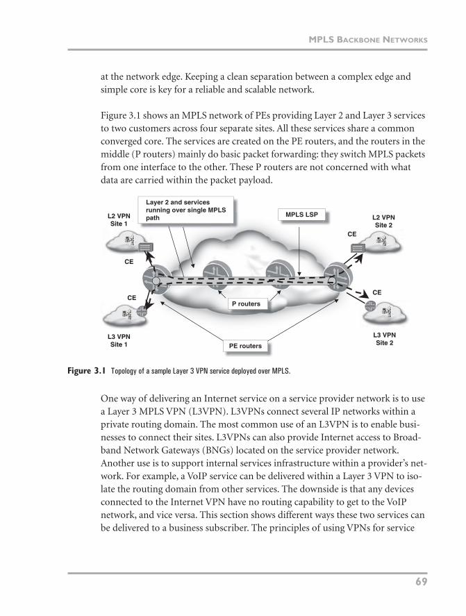
Figure 3.1 shows an MPLS network of PEs providing Layer 2 and Layer 3 services to two customers across four separate sites. All these services share a common converged core. The services are created on the PE routers, and the routers in the middle (P routers) mainly do basic packet forwarding: they switch MPLS packets from one interface to the other. These P routers are not concerned with what data are carried within the packet payload.
Figure 3.1
Topology of a sample Layer 3 VPN service deployed over MPLS.
One way of delivering an Internet service on a service provider network is to use a Layer 3 MPLS VPN (L3VPN). L3VPNs connect several IP networks within a private routing domain. The most common use of an L3VPN is to enable busi-nesses to connect their sites. L3VPNs can also provide Internet access to Broad-band Network Gateways (BNGs) located on the service provider network. Another use is to support internal services infrastructure within a provider’s net-work. For example, a VoIP service can be delivered within a Layer 3 VPN to iso-late the routing domain from other services. The downside is that any devices connected to the Internet VPN have no routing capability to get to the VoIP network, and vice versa. This section shows different ways these two services can be delivered to a business subscriber. The principles of using VPNs for service
P routers
MPLS LSP
L3 VPNL3 VPNSite 2Site 2
L3 VPNL3 VPNSite 1Site 1
L2 VPNL2 VPNSite 1Site 1
L2 VPNL2 VPNSite 2Site 2
PE routers
Layer 2 and servicesrunning over single MPLSpath
CECE
CECECECE
CECE
06_Hellberg_ch03.fm Page 69 Monday, April 9, 2007 12:36 PM
C
HAPTER
3 D
ESIGNING
A
T
RIPLE
-P
LAY
B
ACKBONE
70
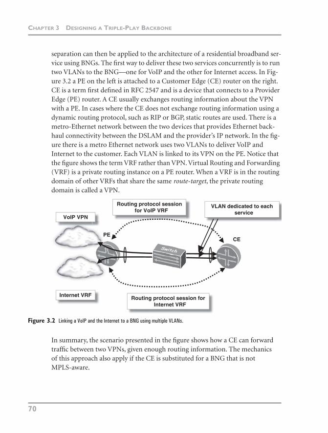
separation can then be applied to the architecture of a residential broadband ser-vice using BNGs. The first way to deliver these two services concurrently is to run two VLANs to the BNG—one for VoIP and the other for Internet access. In Fig-ure 3.2 a PE on the left is attached to a Customer Edge (CE) router on the right. CE is a term first defined in RFC 2547 and is a device that connects to a Provider Edge (PE) router. A CE usually exchanges routing information about the VPN with a PE. In cases where the CE does not exchange routing information using a dynamic routing protocol, such as RIP or BGP, static routes are used. There is a metro-Ethernet network between the two devices that provides Ethernet back-haul connectivity between the DSLAM and the provider’s IP network. In the fig-ure there is a metro Ethernet network uses two VLANs to deliver VoIP and Internet to the customer. Each VLAN is linked to its VPN on the PE. Notice that the figure shows the term VRF rather than VPN. Virtual Routing and Forwarding (VRF) is a private routing instance on a PE router. When a VRF is in the routing domain of other VRFs that share the same
route-target
, the private routing domain is called a VPN.
Figure 3.2
Linking a VoIP and the Internet to a BNG using multiple VLANs.
In summary, the scenario presented in the figure shows how a CE can forward traffic between two VPNs, given enough routing information. The mechanics of this approach also apply if the CE is substituted for a BNG that is not MPLS-aware.
VLAN dedicated to eachservice
Internet VRF Routing protocol session forInternet VRF
Routing protocol sessionfor VoIP VRF
CEPE
VoIP VPN
06_Hellberg_ch03.fm Page 70 Monday, April 9, 2007 12:36 PM
MPLS B
ACKBONE
N
ETWORKS
71
P
OLICY
F
ORWARDING
Instead of using a VLAN per service, a single VLAN between the PE and CE can transport the two services. A technique called policy forwarding is done on the PE to forward traffic to and from the customer into the correct VRF.
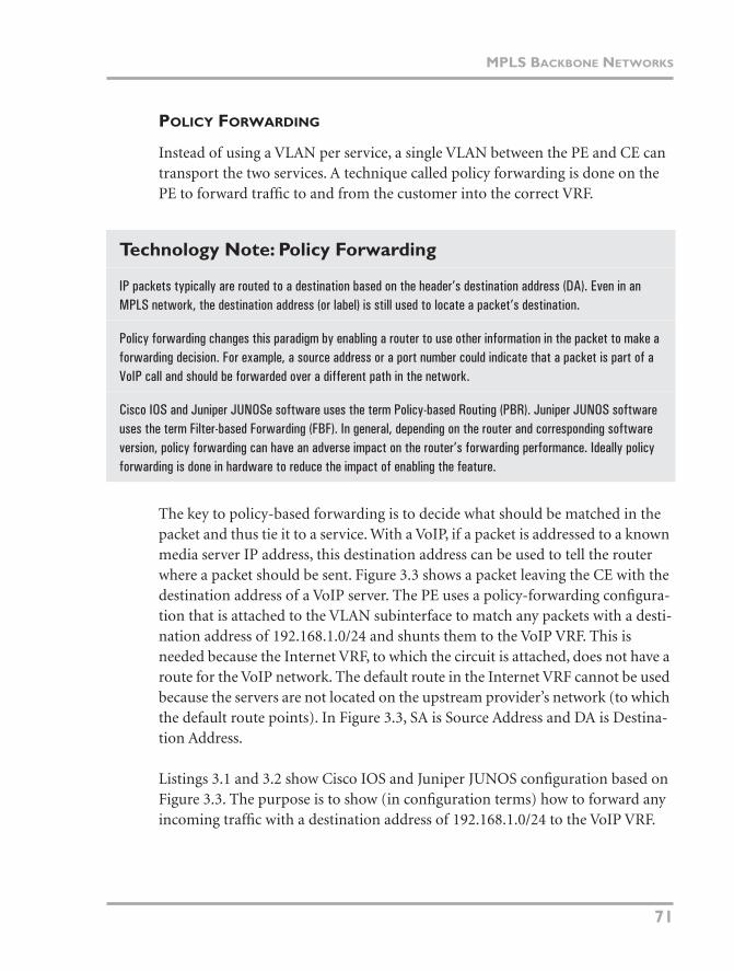
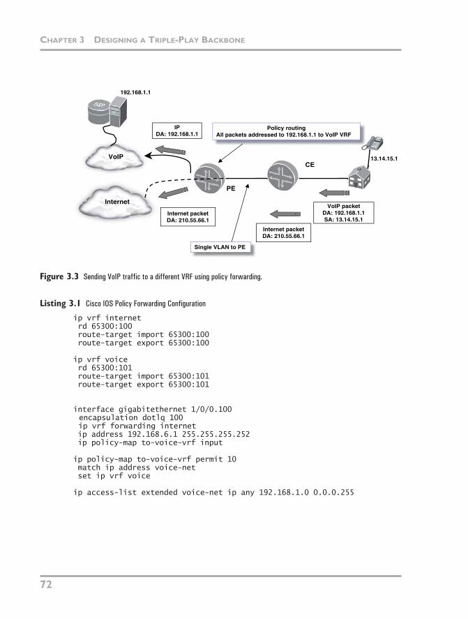
The key to policy-based forwarding is to decide what should be matched in the packet and thus tie it to a service. With a VoIP, if a packet is addressed to a known media server IP address, this destination address can be used to tell the router where a packet should be sent. Figure 3.3 shows a packet leaving the CE with the destination address of a VoIP server. The PE uses a policy-forwarding configura-tion that is attached to the VLAN subinterface to match any packets with a desti-nation address of 192.168.1.0/24 and shunts them to the VoIP VRF. This is needed because the Internet VRF, to which the circuit is attached, does not have a route for the VoIP network. The default route in the Internet VRF cannot be used because the servers are not located on the upstream provider’s network (to which the default route points). In Figure 3.3, SA is Source Address and DA is Destina-tion Address.
Listings 3.1 and 3.2 show Cisco IOS and Juniper JUNOS configuration based on Figure 3.3. The purpose is to show (in configuration terms) how to forward any incoming traffic with a destination address of 192.168.1.0/24 to the VoIP VRF.
Technology Note: Policy Forwarding
IP packets typically are routed to a destination based on the header’s destination address (DA). Even in an MPLS network, the destination address (or label) is still used to locate a packet’s destination.
Policy forwarding changes this paradigm by enabling a router to use other information in the packet to make a forwarding decision. For example, a source address or a port number could indicate that a packet is part of a VoIP call and should be forwarded over a different path in the network.
Cisco IOS and Juniper JUNOSe software uses the term Policy-based Routing (PBR). Juniper JUNOS software uses the term Filter-based Forwarding (FBF). In general, depending on the router and corresponding software version, policy forwarding can have an adverse impact on the router’s forwarding performance. Ideally policy forwarding is done in hardware to reduce the impact of enabling the feature.
06_Hellberg_ch03.fm Page 71 Monday, April 9, 2007 12:36 PM
C
HAPTER
3 D
ESIGNING
A
T
RIPLE
-P
LAY
B
ACKBONE
72
Figure 3.3
Sending VoIP traffic to a different VRF using policy forwarding.
Listing 3.1
Cisco IOS Policy Forwarding Configuration
ip vrf internet rd 65300:100 route-target import 65300:100 route-target export 65300:100
ip vrf voice rd 65300:101 route-target import 65300:101 route-target export 65300:101
interface gigabitethernet 1/0/0.100encapsulation dotlq 100ip vrf forwarding internet
ip address 192.168.6.1 255.255.255.252 ip policy-map to-voice-vrf input
ip policy-map to-voice-vrf permit 10 match ip address voice-net set ip vrf voice
ip access-list extended voice-net ip any 192.168.1.0 0.0.0.255
VoIP packetDA: 192.168.1.1SA: 13.14.15.1
Internet
VoIPCE
PE
Policy routingAll packets addressed to 192.168.1.1 to VoIP VRF
Internet packetDA: 210.55.66.1
IPDA: 192.168.1.1
Internet packetDA: 210.55.66.1
13.14.15.1
Single VLAN to PE
192.168.1.1
06_Hellberg_ch03.fm Page 72 Monday, April 9, 2007 12:36 PM
MPLS B
ACKBONE
N
ETWORKS
73
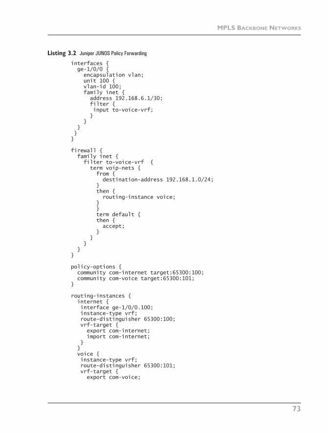
Listing 3.2
Juniper JUNOS Policy Forwarding
interfaces { ge-1/0/0 { encapsulation vlan; unit 100 { vlan-id 100; family inet { address 192.168.6.1/30; filter { input to-voice-vrf; } } } }}
firewall { family inet { filter to-voice-vrf { term voip-nets { from { destination-address 192.168.1.0/24; } then { routing-instance voice; }
}term default {
then { accept; } } } }}
policy-options { community com-internet target:65300:100; community com-voice target:65300:101;}
routing-instances { internet { interface ge-1/0/0.100; instance-type vrf; route-distinguisher 65300:100; vrf-target { export com-internet; import com-internet; } } voice { instance-type vrf; route-distinguisher 65300:101; vrf-target { export com-voice;
06_Hellberg_ch03.fm Page 73 Monday, April 9, 2007 12:36 PM
C
HAPTER
3 D
ESIGNING
A
T
RIPLE
-P
LAY
B
ACKBONE
74
Listing 3.2
continued
import com-voice; } }}
Using the preceding configuration, VoIP data are forwarded to the correct VPN. Return traffic from the VoIP servers needs to be correctly routed back to the CE. Configuring PEs so that traffic is policy forwarded
to
the servers is easier than configuring return traffic back to the CE. The reason is because the servers reside in only a handful of IP networks. A lot more configuration is required on the PEs for return traffic because there are many different destination routes for sub-scribers. Policy routing is useful for some niche applications, but the configura-tion complexity and possible forwarding performance degradation on some routers mean that this is not a widely deployed type of configuration for large-scale applications.
A better alternative is for the PE to merge some of the Internet routes and some of the VoIP routes into a single VRF and then deliver both services down a single VLAN. Distributing routes between two or more VRFs is called route leaking. It involves configuring routing policy on the PE that selects which routes from the VPNs to import to the main VRF instance.
VRF R
OUTE
-T
ARGET
L
EAKING
The preceding section described policy forwarding, which uses relatively static configuration to determine packet-forwarding paths. Routing data from dynamic protocols such as BGP usually cannot be incorporated into the router’s policy-based forwarding decision because the policy forwarding configuration often has to match fields in the packet other than the usual destination address. Route target leaking is a more flexible and dynamic way to allow traffic to flow between VPNs. In an MPLS Layer 3 VPN, routes that belong to the Internet VRF are tagged with a particular community and VoIP routes with another. To allow traffic to flow between the two VPNs, routing policy can be used to match dynamic routing information received from other PEs. If a BGP route passes the policy, it can be imported in to the master VRF. As soon as the routes are in the master VRF, they can be announced over a single routing protocol session to the CE. This also means only a single VLAN is needed to establish multiservice delivery over a single VLAN between the CE and PE. A similar process is done for
06_Hellberg_ch03.fm Page 74 Monday, April 9, 2007 12:36 PM
MPLS B
ACKBONE
N
ETWORKS
75
traffic returning from the servers to the CEs. On the PE that connects to the VoIP servers, customer prefixes that use VoIP services are imported to the VoIP VPN.
The preceding paragraph has shown an example application of route-target leak-ing. However, a VoIP service that is provided to VPN customers usually uses a Session Border Control to interconnect between customer VPNs and a voice VPN. However there are still many applications where route leaking is useful in business VPN or multiservice residential broadband environment.
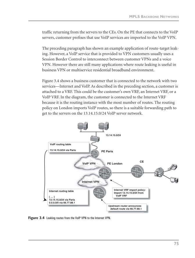
Figure 3.4 shows a business customer that is connected to the network with two services—Internet and VoIP. As described in the preceding section, a customer is attached to a VRF. This could be the customer’s own VRF, an Internet VRF, or a VoIP VRF. In the diagram, the customer is connected to the Internet VRF because it is the routing instance with the most number of routes. The routing policy on London imports VoIP routes, so there is a suitable forwarding path to get to the servers on the 13.14.15.0/24 VoIP server network.
Figure 3.4
Leaking routes from the VoIP VPN to the Internet VPN.
VoIP VPN
Internet VPN
PE LondonCE
Internet VRF import policy:Import 13.14.15.0/24 from
VoIP VRF
Internet routing table
[ … ]13.14.15.0/24 via Paris0.0.0.0/0 via 66.77.88.1
VoIP routing table
13.14.15.0/24 via Paris
13.14.15.0/24
PE Paris
Upstream router announcesdefault route via 66.77.88.1
06_Hellberg_ch03.fm Page 75 Monday, April 9, 2007 12:36 PM
C
HAPTER
3 D
ESIGNING
A
T
RIPLE
-P
LAY
B
ACKBONE
76
This approach of using route target leaking is widely deployed in provider net-works that use VPNs for service separation. It relies on BGP route target commu-nities, which are a convenient way of attaching an identifier to a route, which can then be used in conjunction with routing policy throughout a network. Multiple route target communities can also be attached to a route for more fine-grained routing policy control.
Nevertheless, for providers that are new entrants to the market or that have little use for VPN technology except for business connections, the ideal approach is to put all public-facing devices in a common, global routing instance.
H
YBRID
VPN
AND
N
ON
-VPN R
OUTING
M
ODELS
The previous sections have focused on backbone networks that use VPNs for multiservice transport. This is common with incumbent telcos that are migrat-ing customers off legacy ATM and Frame Relay VPNs to Layer 3 VPNs. Because these providers are comfortable with the concept of customer separation using VPNs, it is a common step to have service separation using VPNs.
However, such a pervasive use of VPNs is not required. In fact, in a residential broadband environment, it is actually more preferable to have a single routing domain for all common public services. This simplifies routing policy and packet forwarding because there does not need to be any complex route leaking or policy forwarding on PEs. In this model, the security implications in the network are effec-tively the same compared to the split-VPN approach, because the server and service layers enforce security rather than the PE network edges. VPN service separation does add some security advantage by being separated from other routing domains as long as VPNs are strictly isolated from each other by a firewall layer
A single multiservice global routing table is still compatible with an MPLS envi-ronment. An MPLS network can provide traffic engineering, fast reroute, and QoS capabilities using the signaling protocol—Resource Reservation Protocol with Traffic Engineering (RSVP-TE) extensions. Alternatively, the Label Distribution Protocol (LDP) signaling protocol can set up basic MPLS traffic routing paths. If a single multiservice, global routing table is used, Label Switched Paths (LSPs) are
06_Hellberg_ch03.fm Page 76 Monday, April 9, 2007 12:36 PM
MPLS BACKBONE NETWORKS
77
still signaled between PE routers. But instead of routes being advertised through-out the domain as labeled VPN routes, they are basic IPv4 or IPv6 routes. This means that they are all present in the main routing table instead of being inside individual VRF tables. However, the next-hop of the routes is resolved across the MPLS LSPs instead of the typical hop-by-hop IPv4/IPv6 routing.
NON-MPLS NETWORKS
Non-MPLS networks are a rarer occurrence. Service providers that do run a pure IPv4 core run a global routing table for all services, including the Internet. The properties of this network are similar to the scenario described previously of using MPLS for forwarding but not using a VPN. The difference is that it is not possible to have any MPLS-based QoS, end-to-end traffic engineering, band-width reservation, fast reroute, or VPN capabilities. These networks are common among smaller providers because the architecture is a tried and tested model that has been used for many years. The network size is usually smaller, so the over-head of MPLS with only a handful of routers may not be worth it (unless Layer 2 or Layer 3 VPN services are needed).
WHAT TYPE OF NETWORK IS BEST?
The designs presented in this chapter are weighted in favor of MPLS. MPLS solves many of the limitations of a hop-by-hop routing paradigm that has been in use since the Internet Protocol was the subject of a cutting-edge RFC.
If running MPLS is a fait accompli, the first question that needs to be answered is whether to use a global routing table for most services or to dedicate a VRF for each service. This is not so easy to answer. From a routing perspective, an Inter-net service is different from most other ones. For example, routes received from other peering routers can contain many BGP attributes that need to be inspected, sometimes modified, and then passed around the rest of the network. The net-work might not be a simple flat domain of BGP routers and could cross interpro-vider VPNs (see the following Technology Note), dedicated peering routers between Internet peers, or edge routers that are not running MPLS. If an Internet service is run in a VRF, to be effective, all PE routers should have as much routing-policy control over MPLS-labeled Internet routes as nonlabeled (non-VPN) ones. Such capabilities vary from vendor to vendor, but day-to-day they
06_Hellberg_ch03.fm Page 77 Monday, April 9, 2007 12:36 PM
CHAPTER 3 DESIGNING A TRIPLE-PLAY BACKBONE
78
are sufficient to keep most operators happy. However, every so often a policy, routing, or IP application feature has limitations working in a VRF; this is com-mon with many vendors. Often implementing such a feature in a VRF is a few releases behind the non-VRF case, but for other cases, the delay is significant or not planned. This comes down to careful planning and testing if the requirement is an Internet service within a VRF. One example of this overhead is a multicast service. Implementing multicast routing and forwarding in a Layer 3 VPN envi-ronment (using the Rosen draft) is a lot more complicated than a simple non-VPN architecture. Because the Rosen draft has several versions, the very latest support varies from vendor to vendor.
If VPNs are used for service separation, there needs to be a way of routing between them. Policy forwarding is one option, but it does not scale well when many services are applied to a customer interface, because the configuration is difficult to manage. It is a useful feature to solve tricky routing issues in isolated cases, but it is not an ideal candidate to use for rolling out multiservice access on a large scale. VRF route leaking is the most common solution for VPN providers to enable inter-VPN routing. The downside is that as the number of services grows, managing and configuring leaking for each service VPN becomes a signif-icant overhead. Life can be made easier when a common set of services are man-aged from a single routing entity—either a “service VRF” or a non-VRF-based routing table.
That said, providers that deploy VPNs as the mainstay of their business often have no problem running Internet and other services in VRFs, because the
Technology Note: Interprovider VPNs
Interprovider VPNs (also known as Carrier-Supporting-Carrier VPNs) are a way for service providers to inter-connect MPLS-based VPNs across provider domains. Because most providers cannot offer complete interna-tional or sometimes national connectivity, they can set up peering points. At these peering points, customer VPN routes are exchanged with other another service provider. This lets them expand their service coverage without the customers having to do it themselves.
Interprovider VPNs are also used within a single company to bridge separate administrative domains. These are common after mergers and acquisitions. These VPNs are sometimes used in a wholesale broadband access model, where the incumbent offers access to wholesaled subscribers through an interprovider VPN.
06_Hellberg_ch03.fm Page 78 Monday, April 9, 2007 12:36 PM
MULTICAST PROTOCOLS IN THE BACKBONE
79
overhead of configuring route leaking and complex BGP configuration is routine business. At the other end of the spectrum are ISPs, where the focus has been on providing Internet access and it’s typical to put Internet and supplementary routes in the global routing table, which results in a simpler configuration.
MULTICAST PROTOCOLS IN THE BACKBONE
The last few sections gave a quick introduction to the designs of double-play core networks. The next set of services to cover is video, which includes both IPTV and unicast Video on Demand (VoD). As far as the core network is concerned, with the exception of QoS configuration, adding VoD is much simpler compared to multicast-based IPTV. This is because VoD has forwarding requirements simi-lar to other high-priority traffic that may already be on the network. This section explains strategies for designing a multicast-capable core, covering both MPLS and non-MPLS networks. Associated supporting protocols and technologies such as point-to-multipoint LSPs, VPLS, and vanilla IPv4 are also explained. You must be familiar with the basic concepts of multicast. Some are explained in the section “Hybrid 1:1 and Multicast VLANs” in Chapter 4, “Designing a Triple-Play Access Network.”
DEPLOYING NATIVE IP MULTICAST
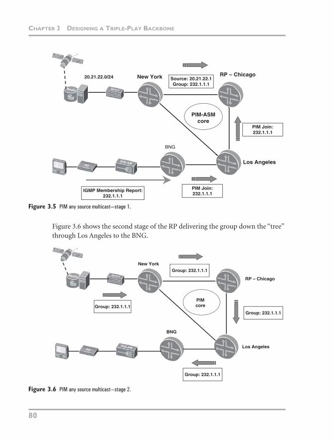
Multicast has been around as long as unicast and is still undergoing continual changes to its routing protocols. Native multicast involves sending data around a network as pure IP packets rather than over some kind of tunnel (such as Generic Routing Encapsulation [GRE] or Layer 2 Tunneling Protocol [L2TP]) or over the top of an MPLS network. All routers involved with forwarding multicast data also participate in the multicast routing domain and have firsthand knowl-edge of and influence over how multicast flows over the network. PIM is the pro-tocol in the core that distributes the routing information. Figure 3.5 shows the standard model of a PIM Any Source Multicast (PIM-ASM) network with a con-tent injection point—New York, an RP, Chicago—and the interested receiver, the BNG. The content injection point first sends the group to the RP. The RP is also the router toward which all last-hop routers (the BNG in this case) send their PIM Join message. The BNG attached to Los Angeles sends a PIM Join to Chi-cago, requesting group 232.1.1.1.
06_Hellberg_ch03.fm Page 79 Monday, April 9, 2007 12:36 PM
CHAPTER 3 DESIGNING A TRIPLE-PLAY BACKBONE
80
Figure 3.5 PIM any source multicast—stage 1.
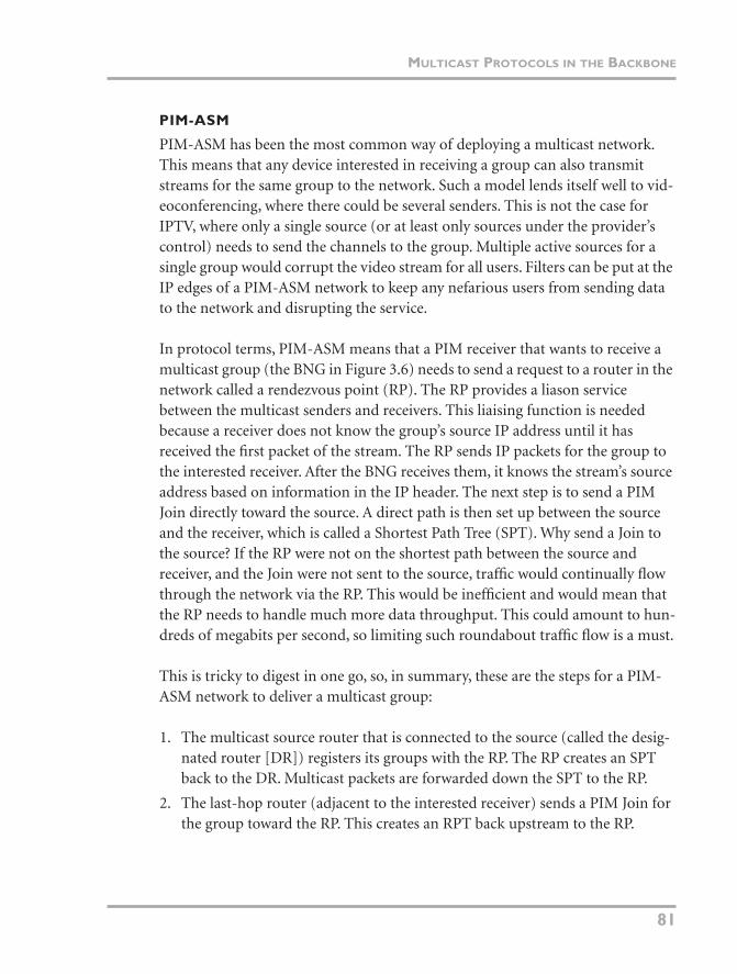
Figure 3.6 shows the second stage of the RP delivering the group down the “tree” through Los Angeles to the BNG.
Figure 3.6 PIM any source multicast—stage 2.
Los Angeles
RP – ChicagoNew York
BNG
Source: 20.21.22.1Group: 232.1.1.1
PIM-ASMcore
PIM Join:232.1.1.1
PIM Join:232.1.1.1
IGMP Membership Report:232.1.1.1
20.21.22.0/24
Los Angeles
RP – Chicago
New York
BNG
Group: 232.1.1.1
Group: 232.1.1.1
Group: 232.1.1.1
Group: 232.1.1.1
PIMcore
06_Hellberg_ch03.fm Page 80 Monday, April 9, 2007 12:36 PM
MULTICAST PROTOCOLS IN THE BACKBONE
81
PIM-ASM
PIM-ASM has been the most common way of deploying a multicast network. This means that any device interested in receiving a group can also transmit streams for the same group to the network. Such a model lends itself well to vid-eoconferencing, where there could be several senders. This is not the case for IPTV, where only a single source (or at least only sources under the provider’s control) needs to send the channels to the group. Multiple active sources for a single group would corrupt the video stream for all users. Filters can be put at the IP edges of a PIM-ASM network to keep any nefarious users from sending data to the network and disrupting the service.
In protocol terms, PIM-ASM means that a PIM receiver that wants to receive a multicast group (the BNG in Figure 3.6) needs to send a request to a router in the network called a rendezvous point (RP). The RP provides a liason service between the multicast senders and receivers. This liaising function is needed because a receiver does not know the group’s source IP address until it has received the first packet of the stream. The RP sends IP packets for the group to the interested receiver. After the BNG receives them, it knows the stream’s source address based on information in the IP header. The next step is to send a PIM Join directly toward the source. A direct path is then set up between the source and the receiver, which is called a Shortest Path Tree (SPT). Why send a Join to the source? If the RP were not on the shortest path between the source and receiver, and the Join were not sent to the source, traffic would continually flow through the network via the RP. This would be inefficient and would mean that the RP needs to handle much more data throughput. This could amount to hun-dreds of megabits per second, so limiting such roundabout traffic flow is a must.
This is tricky to digest in one go, so, in summary, these are the steps for a PIM-ASM network to deliver a multicast group:
1. The multicast source router that is connected to the source (called the desig-nated router [DR]) registers its groups with the RP. The RP creates an SPT back to the DR. Multicast packets are forwarded down the SPT to the RP.
2. The last-hop router (adjacent to the interested receiver) sends a PIM Join for the group toward the RP. This creates an RPT back upstream to the RP.
06_Hellberg_ch03.fm Page 81 Monday, April 9, 2007 12:36 PM
CHAPTER 3 DESIGNING A TRIPLE-PLAY BACKBONE
82
3. RP delivers the group to the interested last-hop router down the RPT.
4. The interested receiver sends a Join for the group directly to the source address of the packet stream. This creates an SPT back to the DR from the last-hop router.
5. When the receiver receives the group from the source DR (along the SPT), it sends a Prune toward the RP so that it does not continually receive two copies of the same group. The RPT is pruned back to the point at which the last branch occurred. A branch is the point at which the SPT and RPT no longer share the same path.
If multiple anycast RPs are deployed for redundancy or network efficiency rea-sons, a second protocol is required to synchronize the RPs—Multicast Source Discovery Protocol (MSDP). MSDP runs between RPs to distribute information about the multicast groups in the network. Without it, not all RPs would have a full view of what multicast sources were in a network.
Technology Note: Multiple RPs
Multiple RPs are used for redundancy and load distribution in a PIM-ASM multicast network. Described in the section “PIM-ASM,” RPs provide the mapping function between sources and receivers. Any source that needs to transmit to the network, first needs to register its groups with the RP. Also, the receivers need to register their intent to receive a group.
Adding one or more RPs for redundancy can be achieved in several ways—bootstrap router (an IETF PIM stan-dard), Auto-RP (a Cisco-designed protocol using dense-mode PIM), or anycast RP. The most common, anycast, involves each RP having the same loopback IP address ID across all the redundant routers (this IP address is different from the unique Interior Gateway Protocol [IGP] router ID). The anycast IP address is announced to the rest of the network in the IGP so that when a PIM router receives several routes for the same IP address, it picks the path to the RP with the lowest IGP cost. Other routers might have a lower cost to reach a different RP because they are closer (in routing protocol terms) to the other RP. In the event of an RP failure, the route is withdrawn (hopefully) from the network, and all the routers choose the remaining RP as their preferred ren-dezvous point.
06_Hellberg_ch03.fm Page 82 Monday, April 9, 2007 12:36 PM
MULTICAST PROTOCOLS IN THE BACKBONE
83
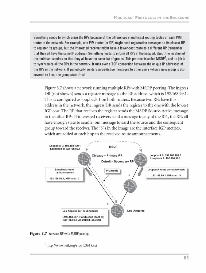
Figure 3.7 shows a network running multiple RPs with MSDP peering. The ingress DR (not shown) sends a register message to the RP address, which is 192.168.99.1. This is configured as loopback 1 on both routers. Because two RPs have this address in the network, the ingress DR sends the register to the one with the lowest IGP cost. The RP that receives the register sends the MSDP Source-Active message to the other RPs. If interested receivers send a message to any of the RPs, the RPs all have enough state to send a Join message toward the source and the consequent group toward the receiver. The “5”s in the image are the interface IGP metrics, which are added at each hop to the received route announcements.
Figure 3.7 Anycast RP with MSDP peering.
Something needs to synchronize the RPs because of the differences in multicast routing tables of each PIM router in the network. For example, one PIM router (or DR) might send registration messages to its closest RP to register its groups, but the interested receiver might have a lower-cost route to a different RP (remember that they all have the same IP address). Something needs to inform all RPs in the network about the location of the multicast senders so that they all have the same list of groups. This protocol is called MSDP1, and its job is to synchronize all the RPs in the network. It runs over a TCP connection between the unique IP addresses of the RPs in the network. It periodically sends Source-Active messages to other peers when a new group is dis-covered to keep the group state fresh.
MSDP
Los Angeles IGP routing table
>192.168.99.1 via Chicago (cost 15)192.168.99.1 via Detroit (cost 20)
Loopback 0: 192.168.100.1Loopback 1: 192.168.99.1
Loopback 0: 192.168.100.2Loopback 1: 192.168.99.1
Loopback routeannouncement
192.168.99.1, IGP cost 10
Loopback route announcement
192.168.99.1, IGP cost 10
Chicago – Primary RP
Los Angeles
Detroit – Secondary RP
PIM traffic
5
55
1 http://www.ietf.org/rfc/rfc3618.txt
06_Hellberg_ch03.fm Page 83 Monday, April 9, 2007 12:36 PM
CHAPTER 3 DESIGNING A TRIPLE-PLAY BACKBONE
84
Bootstrapping the ASM Domain with BSR
Buried further in the multicast tool chest, BSR (bootstrap router) is used to dis-tribute the IP addresses of RPs around the network. Rather than statically config-uring RP addresses on every PIM router, the BSR protocol can distribute this information automatically throughout the PIM domain when the domain is first initialized (or when the BSR goes down). First, each PIM router running the BSR protocol is configured with a priority value. It then becomes a candidate BSR (C-BSR). If it wants to become an RP for a group or a range of groups, this is also configured along with a priority; the router is now a candidate RP (C-RP). The router with the highest BSR priority becomes the BSR, which then arbitrates between the C-RPs to decide which RP is responsible for a given group or group range. In the event of a priority tie, the router with the highest IP address wins the point of contention.
If you’re thinking that all this seems rather complicated, you would be right. PIM-SSM (Source-Specific Multicast) removes much of the complexity associ-ated with PIM-ASM in one fell swoop. It eliminates RPs, MSDP, and BSR from the network; it is becoming the plumbing protocol of choice for IPTV service delivery. The next section explains how this works.
Using PIM Source-Specific Multicast
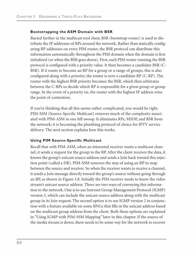
Recall that with PIM-ASM, when an interested receiver wants a multicast chan-nel, it sends a request for the group to the RP. After the client receives the data, it knows the group’s unicast source address and sends a Join back toward this injec-tion point (called a DR). PIM-SSM removes the step of using an RP to map between the source and receiver. So when the receiver wants to receive a channel, it sends a Join message directly toward the group’s source without going through an RP, as shown in Figure 3.8. Initially the PIM receiver needs to know the video stream’s unicast source address. There are two ways of conveying this informa-tion to the network. One is to use Internet Group Management Protocol (IGMP) version 3, which can include the unicast source address along with the multicast group in its Join request. The second option is to use IGMP version 2 in conjunc-tion with a feature available on some BNGs that fills in the unicast address based on the multicast group address from the client. Both these options are explained in “Using IGMP with PIM-SSM Mapping” later in this chapter. If the source of the media stream is down, there needs to be some way for the network to recover
06_Hellberg_ch03.fm Page 84 Monday, April 9, 2007 12:36 PM
MULTICAST PROTOCOLS IN THE BACKBONE
85
from this situation and choose a different source. This issue is covered in the sec-tion “Designing a Highly Available Core Network.”
Figure 3.8 PIM Any Source Multicast.
USING P2MP LSPS FOR MULTICAST DATA DELIVERY
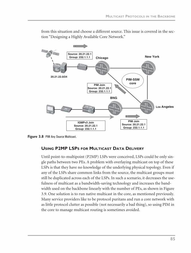
Until point-to-multipoint (P2MP) LSPs were conceived, LSPs could be only sin-gle paths between two PEs. A problem with overlaying multicast on top of these LSPs is that they have no knowledge of the underlying physical topology. Even if any of the LSPs share common links from the source, the multicast groups must still be duplicated across each of the LSPs. In such a scenario, it decreases the use-fulness of multicast as a bandwidth-saving technology and increases the band-width used on the backbone linearly with the number of PEs, as shown in Figure 3.9. One solution is to run native multicast in the core, as mentioned previously. Many service providers like to be protocol puritans and run a core network with as little protocol clutter as possible (not necessarily a bad thing), so using PIM in the core to manage multicast routing is sometimes avoided.
Los Angeles
New YorkChicago
BNG
Source: 20.21.22.1Group: 232.1.1.1
PIM-SSMcore
PIM JoinSource: 20.21.22.1Group: 232.1.1.1
IGMPv3 JoinSource: 20.21.22.1Group: 232.1.1.1
20.21.22.0/24
PIM JoinSource: 20.21.22.1Group: 232.1.1.1
06_Hellberg_ch03.fm Page 85 Monday, April 9, 2007 12:36 PM
CHAPTER 3 DESIGNING A TRIPLE-PLAY BACKBONE
86
Figure 3.9 Traffic duplication of multicast using point-to-point LSPs.
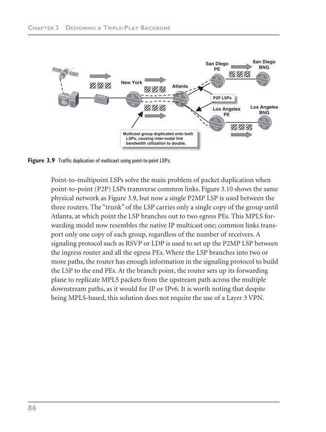
Point-to-multipoint LSPs solve the main problem of packet duplication when point-to-point (P2P) LSPs transverse common links. Figure 3.10 shows the same physical network as Figure 3.9, but now a single P2MP LSP is used between the three routers. The “trunk” of the LSP carries only a single copy of the group until Atlanta, at which point the LSP branches out to two egress PEs. This MPLS for-warding model now resembles the native IP multicast one; common links trans-port only one copy of each group, regardless of the number of receivers. A signaling protocol such as RSVP or LDP is used to set up the P2MP LSP between the ingress router and all the egress PEs. Where the LSP branches into two or more paths, the router has enough information in the signaling protocol to build the LSP to the end PEs. At the branch point, the router sets up its forwarding plane to replicate MPLS packets from the upstream path across the multiple downstream paths, as it would for IP or IPv6. It is worth noting that despite being MPLS-based, this solution does not require the use of a Layer 3 VPN.
New YorkAtlanta
San DiegoPE
Los AngelesPE
Los AngelesBNG
San DiegoBNG
P2P LSPs
Multicast group duplicated onto bothLSPs, causing inter-nodal linkbandwidth utilization to double.
06_Hellberg_ch03.fm Page 86 Monday, April 9, 2007 12:36 PM
MULTICAST PROTOCOLS IN THE BACKBONE
87
Figure 3.10 Point-to-multipoint LSP overview.
The Signaling Plane
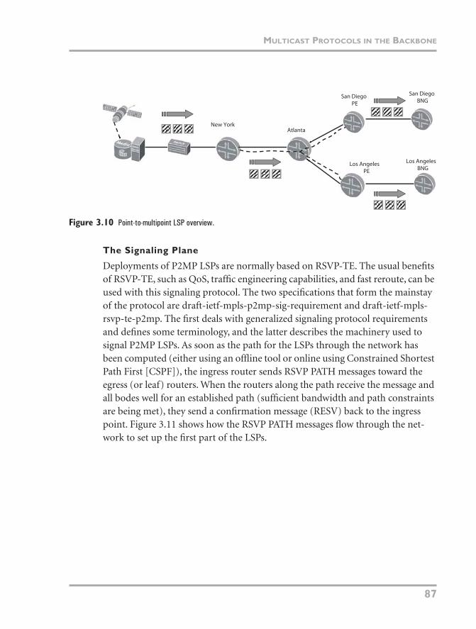
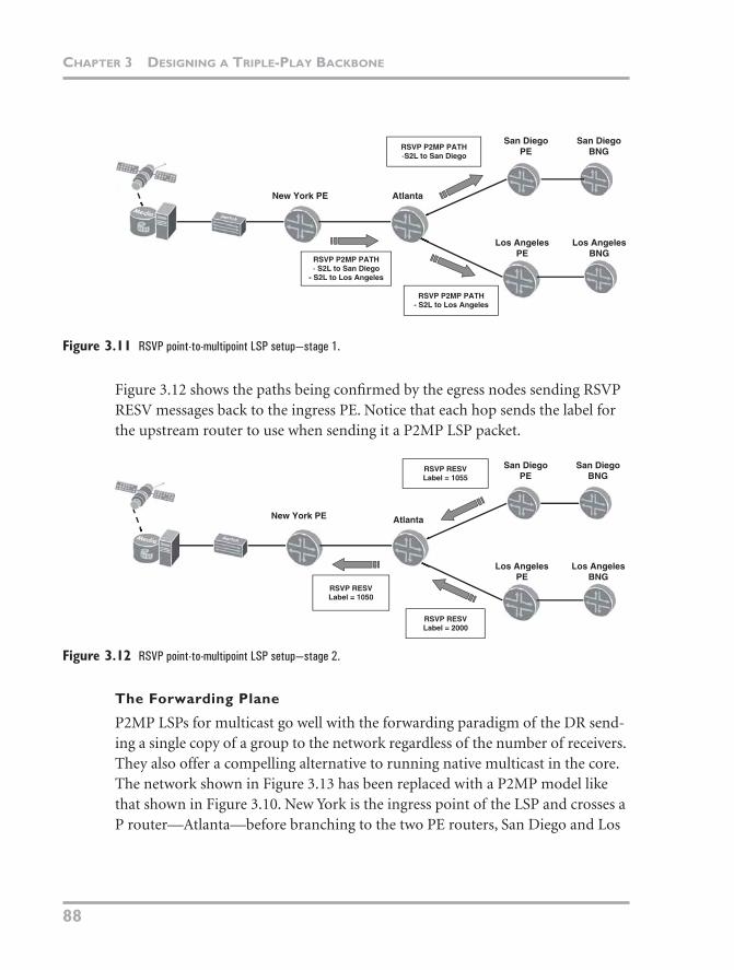
Deployments of P2MP LSPs are normally based on RSVP-TE. The usual benefits of RSVP-TE, such as QoS, traffic engineering capabilities, and fast reroute, can be used with this signaling protocol. The two specifications that form the mainstay of the protocol are draft-ietf-mpls-p2mp-sig-requirement and draft-ietf-mpls-rsvp-te-p2mp. The first deals with generalized signaling protocol requirements and defines some terminology, and the latter describes the machinery used to signal P2MP LSPs. As soon as the path for the LSPs through the network has been computed (either using an offline tool or online using Constrained Shortest Path First [CSPF]), the ingress router sends RSVP PATH messages toward the egress (or leaf) routers. When the routers along the path receive the message and all bodes well for an established path (sufficient bandwidth and path constraints are being met), they send a confirmation message (RESV) back to the ingress point. Figure 3.11 shows how the RSVP PATH messages flow through the net-work to set up the first part of the LSPs.
New YorkAtlanta
San DiegoPE
Los AngelesPE
Los AngelesBNG
San DiegoBNG
06_Hellberg_ch03.fm Page 87 Monday, April 9, 2007 12:36 PM
CHAPTER 3 DESIGNING A TRIPLE-PLAY BACKBONE
88
Figure 3.11 RSVP point-to-multipoint LSP setup—stage 1.
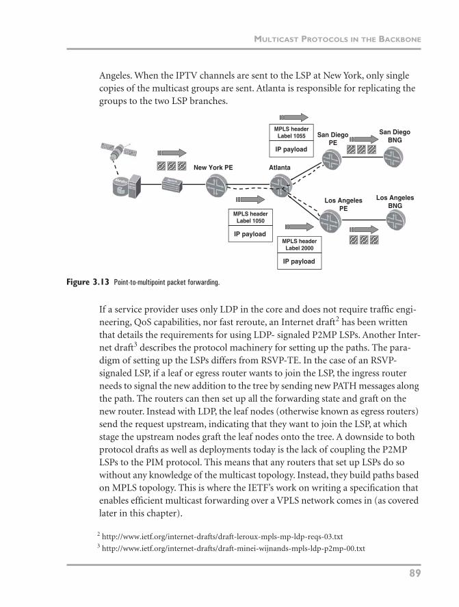
Figure 3.12 shows the paths being confirmed by the egress nodes sending RSVP RESV messages back to the ingress PE. Notice that each hop sends the label for the upstream router to use when sending it a P2MP LSP packet.
Figure 3.12 RSVP point-to-multipoint LSP setup—stage 2.
The Forwarding Plane
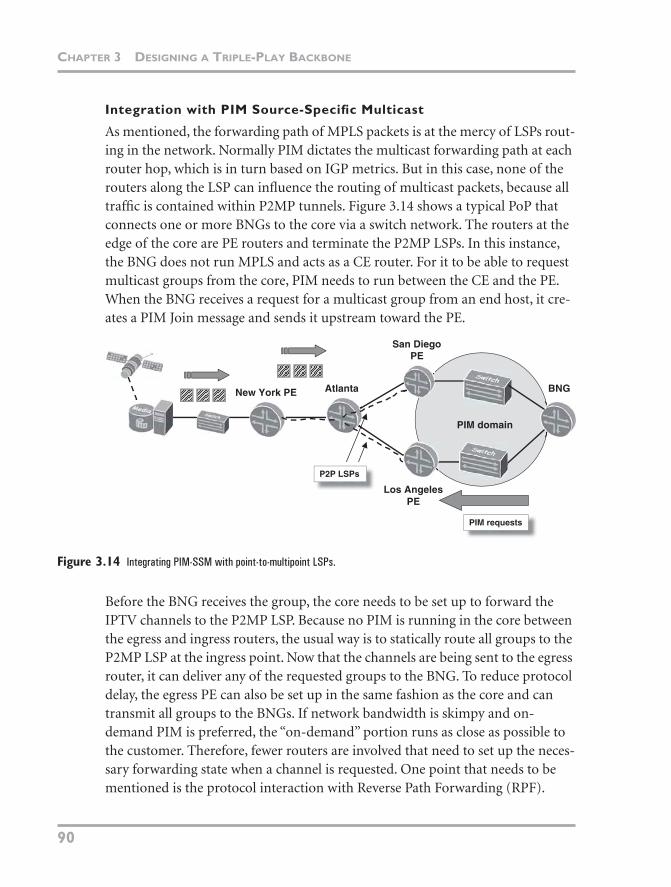
P2MP LSPs for multicast go well with the forwarding paradigm of the DR send-ing a single copy of a group to the network regardless of the number of receivers. They also offer a compelling alternative to running native multicast in the core. The network shown in Figure 3.13 has been replaced with a P2MP model like that shown in Figure 3.10. New York is the ingress point of the LSP and crosses a P router—Atlanta—before branching to the two PE routers, San Diego and Los
New York PE Atlanta
San DiegoPE
Los AngelesPE
Los AngelesBNG
San DiegoBNG
RSVP P2MP PATH- S2L to San Diego
- S2L to Los Angeles
RSVP P2MP PATH- S2L to Los Angeles
RSVP P2MP PATH-S2L to San Diego
New York PE Atlanta
San DiegoPE
Los AngelesPE
Los AngelesBNG
San DiegoBNG
RSVP RESVLabel = 1050
RSVP RESVLabel = 2000
RSVP RESVLabel = 1055
06_Hellberg_ch03.fm Page 88 Monday, April 9, 2007 12:36 PM
MULTICAST PROTOCOLS IN THE BACKBONE
89
Angeles. When the IPTV channels are sent to the LSP at New York, only single copies of the multicast groups are sent. Atlanta is responsible for replicating the groups to the two LSP branches.
Figure 3.13 Point-to-multipoint packet forwarding.
If a service provider uses only LDP in the core and does not require traffic engi-neering, QoS capabilities, nor fast reroute, an Internet draft2 has been written that details the requirements for using LDP- signaled P2MP LSPs. Another Inter-net draft3 describes the protocol machinery for setting up the paths. The para-digm of setting up the LSPs differs from RSVP-TE. In the case of an RSVP-signaled LSP, if a leaf or egress router wants to join the LSP, the ingress router needs to signal the new addition to the tree by sending new PATH messages along the path. The routers can then set up all the forwarding state and graft on the new router. Instead with LDP, the leaf nodes (otherwise known as egress routers) send the request upstream, indicating that they want to join the LSP, at which stage the upstream nodes graft the leaf nodes onto the tree. A downside to both protocol drafts as well as deployments today is the lack of coupling the P2MP LSPs to the PIM protocol. This means that any routers that set up LSPs do so without any knowledge of the multicast topology. Instead, they build paths based on MPLS topology. This is where the IETF’s work on writing a specification that enables efficient multicast forwarding over a VPLS network comes in (as covered later in this chapter).
New York PE Atlanta
San DiegoPE
Los AngelesPE
Los AngelesBNG
San DiegoBNG
MPLS headerLabel 1050
MPLS headerLabel 2000
MPLS headerLabel 1055
IP payload
IP payload
IP payload
2 http://www.ietf.org/internet-drafts/draft-leroux-mpls-mp-ldp-reqs-03.txt3 http://www.ietf.org/internet-drafts/draft-minei-wijnands-mpls-ldp-p2mp-00.txt
06_Hellberg_ch03.fm Page 89 Monday, April 9, 2007 12:36 PM
CHAPTER 3 DESIGNING A TRIPLE-PLAY BACKBONE
90
Integration with PIM Source-Specific Multicast
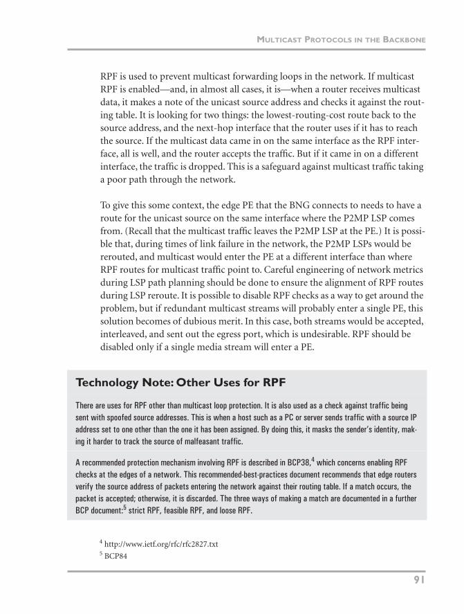
As mentioned, the forwarding path of MPLS packets is at the mercy of LSPs rout-ing in the network. Normally PIM dictates the multicast forwarding path at each router hop, which is in turn based on IGP metrics. But in this case, none of the routers along the LSP can influence the routing of multicast packets, because all traffic is contained within P2MP tunnels. Figure 3.14 shows a typical PoP that connects one or more BNGs to the core via a switch network. The routers at the edge of the core are PE routers and terminate the P2MP LSPs. In this instance, the BNG does not run MPLS and acts as a CE router. For it to be able to request multicast groups from the core, PIM needs to run between the CE and the PE. When the BNG receives a request for a multicast group from an end host, it cre-ates a PIM Join message and sends it upstream toward the PE.
Figure 3.14 Integrating PIM-SSM with point-to-multipoint LSPs.
Before the BNG receives the group, the core needs to be set up to forward the IPTV channels to the P2MP LSP. Because no PIM is running in the core between the egress and ingress routers, the usual way is to statically route all groups to the P2MP LSP at the ingress point. Now that the channels are being sent to the egress router, it can deliver any of the requested groups to the BNG. To reduce protocol delay, the egress PE can also be set up in the same fashion as the core and can transmit all groups to the BNGs. If network bandwidth is skimpy and on-demand PIM is preferred, the “on-demand” portion runs as close as possible to the customer. Therefore, fewer routers are involved that need to set up the neces-sary forwarding state when a channel is requested. One point that needs to be mentioned is the protocol interaction with Reverse Path Forwarding (RPF).
New York PE Atlanta
San DiegoPE
Los AngelesPE
BNG
PIM domain
P2P LSPs
PIM requests
06_Hellberg_ch03.fm Page 90 Monday, April 9, 2007 12:36 PM
MULTICAST PROTOCOLS IN THE BACKBONE
91
RPF is used to prevent multicast forwarding loops in the network. If multicast RPF is enabled—and, in almost all cases, it is—when a router receives multicast data, it makes a note of the unicast source address and checks it against the rout-ing table. It is looking for two things: the lowest-routing-cost route back to the source address, and the next-hop interface that the router uses if it has to reach the source. If the multicast data came in on the same interface as the RPF inter-face, all is well, and the router accepts the traffic. But if it came in on a different interface, the traffic is dropped. This is a safeguard against multicast traffic taking a poor path through the network.
To give this some context, the edge PE that the BNG connects to needs to have a route for the unicast source on the same interface where the P2MP LSP comes from. (Recall that the multicast traffic leaves the P2MP LSP at the PE.) It is possi-ble that, during times of link failure in the network, the P2MP LSPs would be rerouted, and multicast would enter the PE at a different interface than where RPF routes for multicast traffic point to. Careful engineering of network metrics during LSP path planning should be done to ensure the alignment of RPF routes during LSP reroute. It is possible to disable RPF checks as a way to get around the problem, but if redundant multicast streams will probably enter a single PE, this solution becomes of dubious merit. In this case, both streams would be accepted, interleaved, and sent out the egress port, which is undesirable. RPF should be disabled only if a single media stream will enter a PE.
Technology Note: Other Uses for RPF
There are uses for RPF other than multicast loop protection. It is also used as a check against traffic being sent with spoofed source addresses. This is when a host such as a PC or server sends traffic with a source IP address set to one other than the one it has been assigned. By doing this, it masks the sender’s identity, mak-ing it harder to track the source of malfeasant traffic.
A recommended protection mechanism involving RPF is described in BCP38,4 which concerns enabling RPF checks at the edges of a network. This recommended-best-practices document recommends that edge routers verify the source address of packets entering the network against their routing table. If a match occurs, the packet is accepted; otherwise, it is discarded. The three ways of making a match are documented in a further BCP document:5 strict RPF, feasible RPF, and loose RPF.
4 http://www.ietf.org/rfc/rfc2827.txt5 BCP84
06_Hellberg_ch03.fm Page 91 Monday, April 9, 2007 12:36 PM
CHAPTER 3 DESIGNING A TRIPLE-PLAY BACKBONE
92
DELIVERING MULTICAST USING VPLS IN THE CORE
Running multicast over Virtual Private LAN Service (VPLS) is getting lots of attention in the IETF lately—and for good reason. It is shaping up to be an ideal fit for a provider’s internal IPTV transport mechanism and for delivering multi-cast VPN services to external customers as well. The biggest drawback of using VPLS for multicast forwarding is its lack of knowledge of the underlying physical MPLS topology (as described in the preceding section). This results in traffic being unnecessarily duplicated on common network links, as shown in Figure 3.9. Protocol enhancements are being written to allow VPLS to forward multicast traffic more efficiently and to integrate more closely with the underlying trans-port mechanism. For example, today VPLS uses many P2P LSPs for the transport mechanism. An alternative model is to use P2MP LSPs. Chapter 4 has further information on the basics of VPLS.
VPLS is not solely responsible for streamlining multicast replication in the net-work; it builds on other protocols, such as BGP, RSVP, and LDP, to create an effi-cient multicast topology. The discussion in this section is based on the concepts described in the “Multicast over VPLS” Internet draft.6 The first optimization is where VPLS networks that need to carry multicast traffic use multicast trees, which are built using signaling protocols such as RSVP-TE, LDP, or PIM. The
Strict RPF means that the interface where traffic arrives must match the interface that would be used to get back to the source address. Feasible RPF loosens the restriction that there can be only a single route back to the source. For example, if a router receives multiple BGP routes for a network, feasible RPF lets the router choose any of these routes for the RPF check. Such a case would arise if a customer were multihomed and traffic intentionally might not return via the lowest-cost path.
Loose RPF means that there just needs to be any possible route for the traffic, even if it is a default one. This means that traffic with forged source addresses could enter the network via a completely different path than what is expected or valid, defeating the purpose of the RPF check if a default route can match the source of traffic. BCP84/RFC2827 does document one or two use-cases for loose RPF.
Chapter 12, “Security in Broadband Networks,” gives further examples of configuring RPF checks on BRAS routers.
6 http://www.ietf.org/internet-drafts/draft-ietf-l2vpn-vpls-mcast-00.txt
06_Hellberg_ch03.fm Page 92 Monday, April 9, 2007 12:36 PM
MULTICAST PROTOCOLS IN THE BACKBONE
93
second optimization is to allow ingress and egress PEs to auto-discover each other and to enable routers to create multicast trees between themselves. Both of these concepts are explained in the following sections.
Multicast Trees and VPLS
In a basic multicast setup with IPv4 and PIM-ASM, when routers want to join a group, they send messages toward the unicast source or the RP. Core routers deliver the multicast stream out of the interface via the one through which the original request was received. If another edge router wants to receive the same group, a core router can simply replicate the group out of the other interface that it received the new request on rather than the server’s having to send a separate stream. Looking at this from a top-down perspective, it forms what is called a multicast tree and describes the path that a group takes in the network.
VPLS supported with P2MP LSPs does not suffer the problem of sending multi-ple copies of groups across common links that a normal VPLS network does. Because the underlying topology is based on a point-to-multipoint architecture, only one copy of a group is transmitted along a common part of the tree, regard-less of the number of receivers. Only where the tree splits in two parts is the group duplicated out of the different interfaces. The P2MP LSP hierarchy with VPLS is the same as plain P2MP LSPs, so there needs to be an advantage from running all the extra signaling state in the backbone. The first advantage is that point-to-multipoint LSPs can be used for more than just the internal transporta-tion of provider multicast. They can be reused when the service provider offers multicast VPN services to customers. These can coexist on the same LSP as pro-vider multicast services. Because of the extra signaling protocols used in this mechanism, LSPs can be automatically provisioned.
Automated P2MP LSP Provisioning
One of the drawbacks of P2MP LSPs is the amount of static configuration needed on the PEs. In the case of LDP-based LSPs, each of the edge nodes needs to be configured with the details of the LSP tree to join. With RSVP-TE, the ingress router needs to be configured with the addresses of the egress PEs. The draft draft-ietf-l2vpn-vpls-mcast enables ingress and egress PE routers that are
06_Hellberg_ch03.fm Page 93 Monday, April 9, 2007 12:36 PM
CHAPTER 3 DESIGNING A TRIPLE-PLAY BACKBONE
94
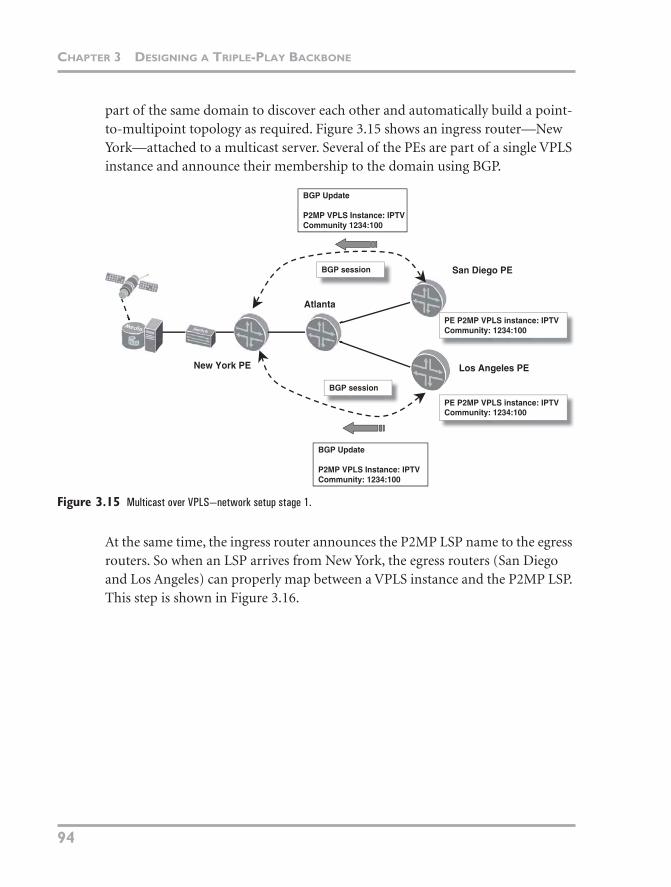
part of the same domain to discover each other and automatically build a point-to-multipoint topology as required. Figure 3.15 shows an ingress router—New York—attached to a multicast server. Several of the PEs are part of a single VPLS instance and announce their membership to the domain using BGP.
Figure 3.15 Multicast over VPLS—network setup stage 1.
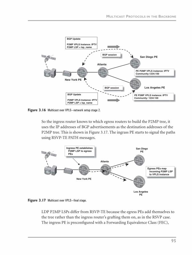
At the same time, the ingress router announces the P2MP LSP name to the egress routers. So when an LSP arrives from New York, the egress routers (San Diego and Los Angeles) can properly map between a VPLS instance and the P2MP LSP. This step is shown in Figure 3.16.
New York PE
Atlanta
BGP session
BGP session
BGP Update
P2MP VPLS Instance: IPTVCommunity: 1234:100
BGP Update
P2MP VPLS Instance: IPTVCommunity 1234:100
PE P2MP VPLS instance: IPTVCommunity: 1234:100
PE P2MP VPLS instance: IPTVCommunity: 1234:100
San Diego PE
Los Angeles PE
06_Hellberg_ch03.fm Page 94 Monday, April 9, 2007 12:36 PM
MULTICAST PROTOCOLS IN THE BACKBONE
95
Figure 3.16 Multicast over VPLS—network setup stage 2.
So the ingress router knows to which egress routers to build the P2MP tree, it uses the IP addresses of BGP advertisements as the destination addresses of the P2MP tree. This is shown in Figure 3.17. The ingrass PE starts to signal the paths using RSVP-TE PATH messages.
Figure 3.17 Multicast over VPLS—final stage.
LDP P2MP LSPs differ from RSVP-TE because the egress PEs add themselves to the tree rather than the ingress router’s grafting them on, as in the RSVP case. The ingress PE is preconfigured with a Forwarding Equivalence Class (FEC),
New York PE
Atlanta
BGP session
BGP session
BGP Update
P2MP VPLS Instance: IPTVP2MP LSP = lsp_name
BGP Update
P2MP VPLS Instance: IPTVP2MP LSP = lsp_name
PE P2MP VPLS instance: IPTVCommunity:1234:100
PE P2MP VPLS instance: IPTVCommunity: 1234:100
Los Angeles PE
San Diego PE
New York PE
Atlanta
Egress PEs mapincoming P2MP LSPto VPLS instance
Ingress PE establishesP2MP LSP to egressPEs
San DiegoPE
Los AngelesPE
06_Hellberg_ch03.fm Page 95 Monday, April 9, 2007 12:36 PM
CHAPTER 3 DESIGNING A TRIPLE-PLAY BACKBONE
96
which can be thought of as an ID for the P2MP LSP. The FEC is sent to the egress PEs using BGP, and any egress routers that are part of the VPLS domain graft themselves onto the P2MP LSP ID that was given in the BGP message.
The Future of VPLS Multicast Delivery
Although it is still a relatively new technology, VPLS has had some time to mature in the marketplace. Basic P2MP LSPs without VPLS have also been on the market for some time. However, the complexity of the VPLS protocol machinery is greater, so development, testing, and deployment take more time. Most of the current VPLS implementations are based on existing P2P LSP ones, so a lot of the initial bugs with the underlying transport layer have been ironed out. The safe option of basic multicast routing using IP forwarding over P2MP LSPs or even simple IP multicast routing will prevail for some time. But as router vendors release software that supports the additional VPLS draft, the benefits of reduced provisioning time and reuse of LDP or RSVP signaling infrastructure will help make the switch to the more flexible network architecture. Just as once it was enough of a payoff to move to a more complex MPLS architecture that offered the benefits of services running on a “converged” platform, VPLS should help the switch from a P2P model.
RUNNING MPLS ON THE BNG
So far, this chapter has focused mainly on backbone and some edge architectures. Because the BNG is a multiservice router, some of the services that are deployed on it impact the way in which it is linked, at a protocol level, to the rest of the network. For instance, if Layer 3 VPNs are required on the BNG, it usually needs to be part of the MPLS cloud (unless Layer 2 Tunneling Protocol is used in the network). To take full advantage of MPLS features such as fast reroute, end-to-end traffic engineering, point-to-point LSPs, VPLS, and a unified network, the BNG should be connected to the MPLS backbone. This section discusses some of the services and protocols deployed on a BNG that affect its connectivity to the backbone, including Layer 3 VPN services and integrating multicast routing pro-tocols with the BNG.
The BNG can connect to PEs via a switch aggregation network or directly using SONET, Gigabit Ethernet, or 10 Gigabit Ethernet. SONET is becoming less com-mon in provider PoPs because Gigabit Ethernet is a cheaper alternative.
06_Hellberg_ch03.fm Page 96 Monday, April 9, 2007 12:36 PM
RUNNING MPLS ON THE BNG
97
One issue with Gigabit Ethernet in the past has been the failure detection mecha-nism. When GE links are connected through a switch aggregation network, link failures cannot always be detected by loss of light and can take seconds to detect. To solve this problem, the industry is moving toward using Bidirectional For-warding Detection (BFD). Basic BFD link detection mode is a lightweight proto-col that sends simple keepalive packets to an IP address of a router sitting on the same broadcast domain. These keepalive packets can detect path failures similar to how ATM OAM cells are used for continuity-check virtual circuits (VCs) and are used by the router to bring down a subinterface if it times out receiving a response from the other end of the BFD session.
CONNECTING THE BNG TO THE WIDER WORLD
Connecting a BNG to the core using plain IP has been a common feature of broadband networks for some time. Because Internet access was the only service that was needed, sophisticated routing and forwarding methods were not used. Connectivity to the rest of the network and the Internet at large would be han-dled by configuring a static default route on the BNG pointing to the upstream router. Or, if some routing dynamism was needed, a routing protocol such as OSPF, IS-IS, and/or BGP would be used. Some service provider architectures lend themselves well to continue running their BNGs in a simple configuration when migrating to a triple-play architecture. For example, if the BNG routers do not provide any locally terminated VPN services and MPLS features are not of interest, the benefits of migrating the BNG to MPLS are minimal.
But if there is a service that requires terminating subscriber sessions in Layer 3 VPNs, the most common model is to terminate them on an L2TP LNS rather than locally-terminated VPNs. This entails the BNG extending subscriber PPP sessions over an IP network using L2TP and terminating them on a centralized router called a Layer 2 Tunneling Protocol Network Server (LNS). The advantage is that each BNG does not need local configuration of each VPN. It simply for-wards each PPP session to one (or possibly one of several) centralized router that has the necessary Layer 3 VPN configuration for that subscriber. Because this functionality is agnostic to whatever packet mechanism is used underneath (MPLS, L2TP, GRE, IP, and so on), there is no affect on L2TP functionality if MPLS is deployed to the BNG. If IPoE services based on DHCP or static
06_Hellberg_ch03.fm Page 97 Monday, April 9, 2007 12:36 PM
CHAPTER 3 DESIGNING A TRIPLE-PLAY BACKBONE
98
configuration are used, L2TP VPN services require a different approach. The first is to use L2TP Version 3, which is more flexible with the type of payload it may carry. The second option is to deploy local VPN configurations on the BNG.
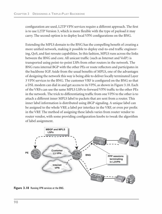
Extending the MPLS domain to the BNG has the compelling benefit of creating a more unified network, making it possible to deploy end-to-end traffic engineer-ing, QoS, and fast reroute capabilities. In this fashion, MPLS runs across the links between the BNG and core. All unicast traffic (such as Internet and VoIP) is transported using point-to-point LSPs from other routers in the network. The BNG runs internal BGP with the other PEs or route reflectors and participates in the backbone IGP. Aside from the usual benefits of MPLS, one of the advantages of designing the network this way is being able to deliver locally terminated Layer 3 VPN services to the BNG. The customer VRF is configured on the BNG so that a DSL modem can dial in and get access to its VPN, as shown in Figure 3.18. Each of the VRFs can use the same MPLS LSPs to forward VPN traffic to the other PEs in the network. The trick to differentiating traffic from one VPN to the other is to attach a different inner MPLS label to packets that are sent from a router. This inner label information is distributed using iBGP signaling. A unique label can be assigned to the whole VRF, a label per interface in the VRF, or even per prefix in the VRF. The method of assigning these labels varies from router vendor to router vendor, with some providing configuration knobs to tweak the algorithm of label assignment.
Figure 3.18 Running VPN services at the BNG.
CustomerL3 VPN
PPP sessionsterminatingin L3VPN
BNGPE
MBGP and MPLSLSPs
InternetVPN
06_Hellberg_ch03.fm Page 98 Monday, April 9, 2007 12:36 PM
RUNNING MPLS ON THE BNG
99
VPN services are not the only services that benefit from MPLS-connected BNGs. High-priority traffic, such as Video on Demand and VoIP, can take advantage of specially reserved LSPs. These LSPs can take a shorter or more reliable path through the network than other LSPs that are used for best-effort traffic. These LSPs can be protected with fast reroute capability to minimize the impact of delays in IGP convergence and path resignaling. It is up to the provider whether lower-priority traffic can use the same LSPs as high-priority traffic. For more complex deployments, often low-priority traffic is forwarded on an LSP with a longer path and lower setup priorities. An LSP with a lower setup priority is one that, in the event of a link break in the network and if there is insufficient band-width to signal a new path at that priority, an LSP with a higher priority value can take its place. If an LSP is dedicated to a particular traffic priority, it is called an L-LSP (label-inferred LSP), compared to an E-LSP, which can carry multiple traffic priorities.
USING IGMP WITH PIM-SSM MAPPING
To request a multicast group from the core, PIM requests it from the upstream router. MPLS or IP forwarding is used as the underlying packet transport, and Internet Group Management Protocol (IGMP) is used by the subscriber to request groups from the BNG.
IGMP is a lightweight protocol that an end host, such as a set-top box, uses when requesting a multicast video channel. An IGMP packet, which is sent toward a PIM router, contains the multicast group address that the host wants to receive. The BNG also can act as an IGMP client of sorts. It is used when the router wants to statically join a group and have the core continually transmit it to the BNG. These are called static IGMP Joins.
Before we race ahead too fast, an explanation of the relationship between IGMP and PIM is needed. IGMP is used by a host (such as a set-top box) to request multicast groups from the network. With IGMP versions 1 and 2, when the set-top box requests a multicast channel, it sends an IGMP Membership Report packet upstream to the BNG that contains the group address it wants to receive. With IGMP version 3, this same packet is called a Join (Figure 3.19 shows an example). IGMP is also used to request that a particular group no longer be sent; the packet is called, unsurprisingly, an IGMP Leave. IGMP does not have much
06_Hellberg_ch03.fm Page 99 Monday, April 9, 2007 12:36 PM
CHAPTER 3 DESIGNING A TRIPLE-PLAY BACKBONE
100
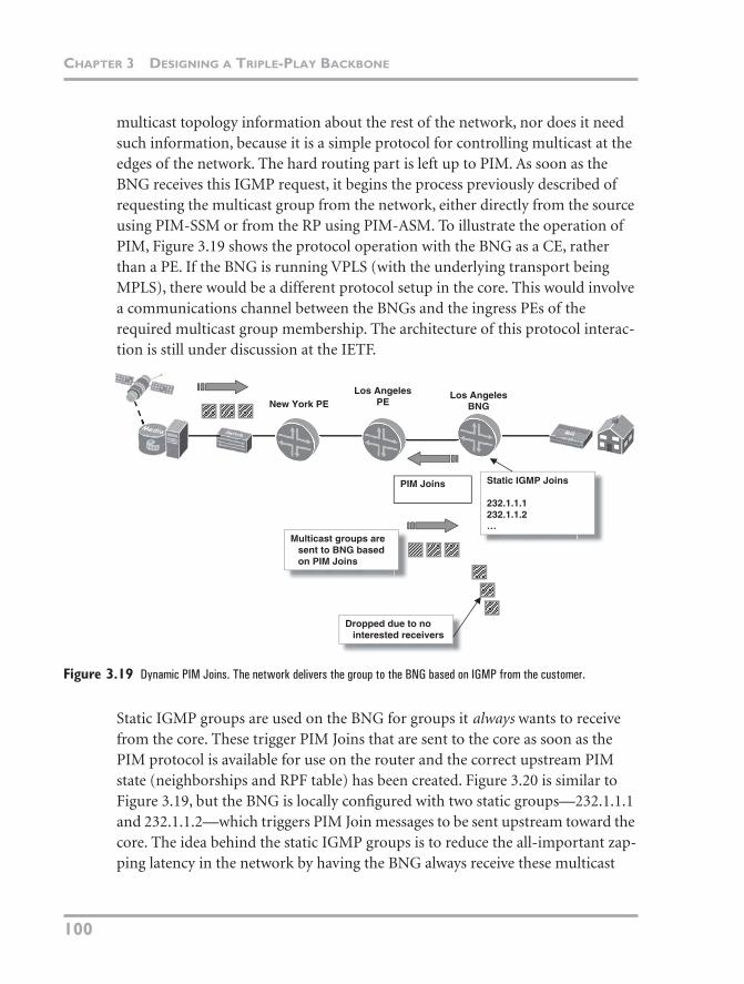
multicast topology information about the rest of the network, nor does it need such information, because it is a simple protocol for controlling multicast at the edges of the network. The hard routing part is left up to PIM. As soon as the BNG receives this IGMP request, it begins the process previously described of requesting the multicast group from the network, either directly from the source using PIM-SSM or from the RP using PIM-ASM. To illustrate the operation of PIM, Figure 3.19 shows the protocol operation with the BNG as a CE, rather than a PE. If the BNG is running VPLS (with the underlying transport being MPLS), there would be a different protocol setup in the core. This would involve a communications channel between the BNGs and the ingress PEs of the required multicast group membership. The architecture of this protocol interac-tion is still under discussion at the IETF.
Figure 3.19 Dynamic PIM Joins. The network delivers the group to the BNG based on IGMP from the customer.
Static IGMP groups are used on the BNG for groups it always wants to receive from the core. These trigger PIM Joins that are sent to the core as soon as the PIM protocol is available for use on the router and the correct upstream PIM state (neighborships and RPF table) has been created. Figure 3.20 is similar to Figure 3.19, but the BNG is locally configured with two static groups—232.1.1.1 and 232.1.1.2—which triggers PIM Join messages to be sent upstream toward the core. The idea behind the static IGMP groups is to reduce the all-important zap-ping latency in the network by having the BNG always receive these multicast
Los AngelesPE
Los AngelesBNG
Static IGMP Joins
232.1.1.1232.1.1.2…
PIM Joins
Multicast groups aresent to BNG basedon PIM Joins
Dropped due to nointerested receivers
New York PE
06_Hellberg_ch03.fm Page 100 Monday, April 9, 2007 12:36 PM
RUNNING MPLS ON THE BNG
101
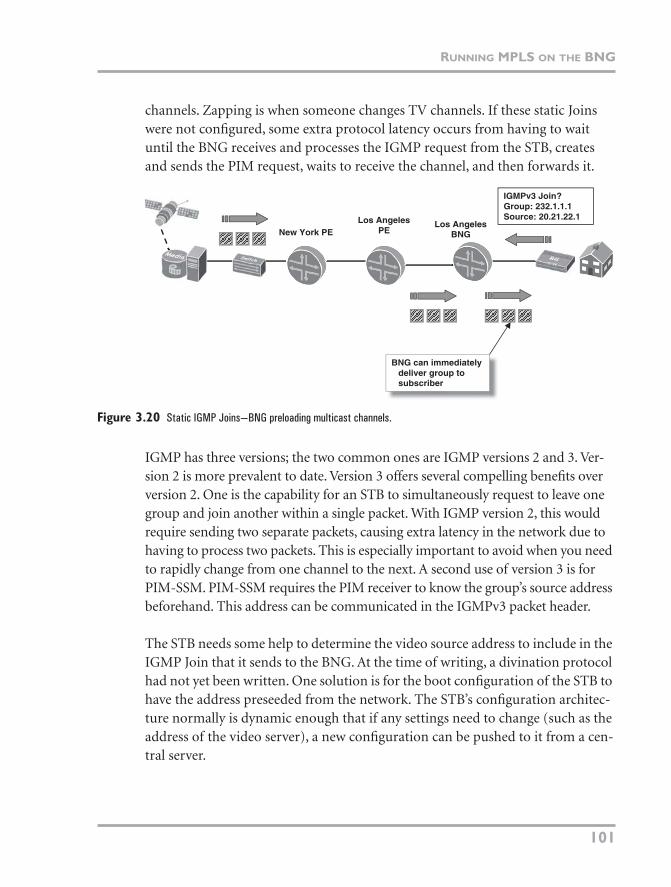
channels. Zapping is when someone changes TV channels. If these static Joins were not configured, some extra protocol latency occurs from having to wait until the BNG receives and processes the IGMP request from the STB, creates and sends the PIM request, waits to receive the channel, and then forwards it.
Figure 3.20 Static IGMP Joins—BNG preloading multicast channels.
IGMP has three versions; the two common ones are IGMP versions 2 and 3. Ver-sion 2 is more prevalent to date. Version 3 offers several compelling benefits over version 2. One is the capability for an STB to simultaneously request to leave one group and join another within a single packet. With IGMP version 2, this would require sending two separate packets, causing extra latency in the network due to having to process two packets. This is especially important to avoid when you need to rapidly change from one channel to the next. A second use of version 3 is for PIM-SSM. PIM-SSM requires the PIM receiver to know the group’s source address beforehand. This address can be communicated in the IGMPv3 packet header.
The STB needs some help to determine the video source address to include in the IGMP Join that it sends to the BNG. At the time of writing, a divination protocol had not yet been written. One solution is for the boot configuration of the STB to have the address preseeded from the network. The STB’s configuration architec-ture normally is dynamic enough that if any settings need to change (such as the address of the video server), a new configuration can be pushed to it from a cen-tral server.
Los AngelesPE
Los AngelesBNG
BNG can immediatelydeliver group tosubscriber
IGMPv3 Join?Group: 232.1.1.1Source: 20.21.22.1
New York PE
06_Hellberg_ch03.fm Page 101 Monday, April 9, 2007 12:36 PM
CHAPTER 3 DESIGNING A TRIPLE-PLAY BACKBONE
102
If the STB cannot specify a source address in the Join packet, all is not lost. Even though IGMP version 3 has a field for the unicast source address, it does not have to be filled in. Version 3 can still be used while leaving the source address field inside the packet empty. Now we’re back to the problem of discovering the source address. The solution is to let the PIM router fill in this information. This is called PIM-SSM mapping, and it is explained shortly.
IGMP Proxy
One feature that has not been mentioned in this chapter is IGMP proxy, which is designed to handle scaling issues in the access and BNG edge. One that is familiar to many is the web proxy; it handles requests for websites on the Internet on behalf of the client sitting behind it. The IGMP proxy works in a similar way by dealing with multicast requests on behalf of the client (or clients) sitting behind it.
Technology Note: Explicit Tracking and Immediate Leave
Every device on a router’s subinterface (such as a multicast VLAN to a DSLAM) that sends and receives IGMP traffic is tracked by the router. If only one host is left on the interface, and it wants to leave the group, the router can immediately stop sending traffic out the interface when it gets the leave message. This was not possible with IGMP version 2, because the protocol did not allow the router to receive Join messages from all clients; one client on a LAN is designated the group speaker.
Cisco calls to the feature of tracking every join and leave of the LAN explicit tracking. Juniper ERX software has a slightly related feature called IGMP immediate leave, which means that as soon as it receives a Leave message on an interface, it stops transmitting out that interface. This should be used only on an interface where there is one IGMP client connected.
Cisco:
This feature can be enabled by configuring the following command under the interface:
ip igmp explicit-tracking
Juniper ERX:
This feature can be enabled by configuring the following command under either an AAA profile or the interface:
ip igmp immediate-leave
06_Hellberg_ch03.fm Page 102 Monday, April 9, 2007 12:36 PM
RUNNING MPLS ON THE BNG
103
One of the more common uses is in a residential gateway (RG), which often functions as an IGMP proxy on behalf of the STB. When someone presses a channel button on the RG remote control, it causes the STB to send an IGMP request upstream to the RG, which intercepts the IGMP request and sends it to the network on its behalf. When the BNG sends the IPTV stream to the RG, it is forwarded to the STB. So why not let the STB send the request directly to the BNG? Similar to a web proxy, one of the reasons is to hide the addressing of the network sitting in the background. For example, the addressing between the STB and the RG might be a private network, so making the STB’s identity visible on the network might not be desirable. Usually, however, the proxy is part of the operation of the RG to track which port the IGMP request came from.
The more important use of the IGMP proxy is described in Chapter 4. It involves the DSLAM handling requests on behalf of all the multicast clients sitting behind it so as to reduce the amount of traffic between the clients and the BNG. For example, if 300 clients are connected to a DSLAM, and they all ask to change the channel at a similar time by sending IGMP packets directly to the BNG (such as at the start of a commercial break), it could be inundated with requests. This is especially true when extrapolating this effect across many DSLAMs. The actual impact and the number of IGMP requests that could adversely affect a BNG’s performance varies between vendors, of course. Using an IGMP proxy on the DSLAM can reduce the control traffic to the BNG by filtering out requests that the DSLAM has already sent and skipping directly to the step of delivering the multicast group to the client. For example, if the DSLAM is already sending an IPTV channel to one host and another host requests the same channel, the DSLAM can suppress the IGMP request to the DSLAM and add the new host to the list of receivers to which it should send the channel.
Usually an IGMP proxy goes hand in hand with IGMP snooping, which is a way for a router or switch to listen to traffic on a port. If it detects an IGMP Join, the switch withdraws the default (with IGMP snooping enabled) restriction, pre-venting the transmission of the group to that port. If this snooping function is not enabled, it causes the multicast to be sent out all ports (except the one it came through), because the destination address of the Ethernet frames is similar to broadcast frames, which need to be sent out all ports in the switching domain.
06_Hellberg_ch03.fm Page 103 Monday, April 9, 2007 12:36 PM
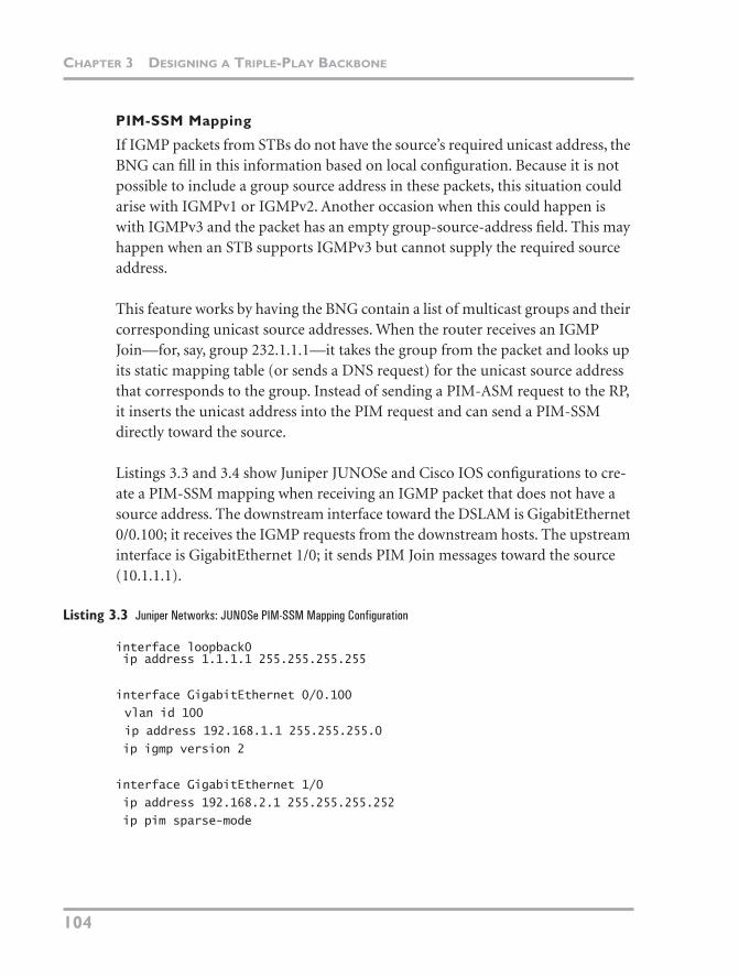
CHAPTER 3 DESIGNING A TRIPLE-PLAY BACKBONE
104
PIM-SSM Mapping
If IGMP packets from STBs do not have the source’s required unicast address, the BNG can fill in this information based on local configuration. Because it is not possible to include a group source address in these packets, this situation could arise with IGMPv1 or IGMPv2. Another occasion when this could happen is with IGMPv3 and the packet has an empty group-source-address field. This may happen when an STB supports IGMPv3 but cannot supply the required source address.
This feature works by having the BNG contain a list of multicast groups and their corresponding unicast source addresses. When the router receives an IGMP Join—for, say, group 232.1.1.1—it takes the group from the packet and looks up its static mapping table (or sends a DNS request) for the unicast source address that corresponds to the group. Instead of sending a PIM-ASM request to the RP, it inserts the unicast address into the PIM request and can send a PIM-SSM directly toward the source.
Listings 3.3 and 3.4 show Juniper JUNOSe and Cisco IOS configurations to cre-ate a PIM-SSM mapping when receiving an IGMP packet that does not have a source address. The downstream interface toward the DSLAM is GigabitEthernet 0/0.100; it receives the IGMP requests from the downstream hosts. The upstream interface is GigabitEthernet 1/0; it sends PIM Join messages toward the source (10.1.1.1).
Listing 3.3 Juniper Networks: JUNOSe PIM-SSM Mapping Configuration
interface loopback0 ip address 1.1.1.1 255.255.255.255
interface GigabitEthernet 0/0.100
vlan id 100
ip address 192.168.1.1 255.255.255.0
ip igmp version 2
interface GigabitEthernet 1/0
ip address 192.168.2.1 255.255.255.252
ip pim sparse-mode
06_Hellberg_ch03.fm Page 104 Monday, April 9, 2007 12:36 PM
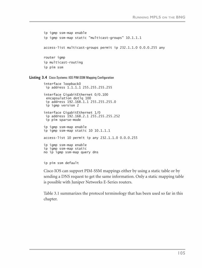
RUNNING MPLS ON THE BNG
105
ip igmp ssm-map enable
ip igmp ssm-map static "multicast-groups" 10.1.1.1
access-list multicast-groups permit ip 232.1.1.0 0.0.0.255 any
router igmp
ip multicast-routing
ip pim ssm
Listing 3.4 Cisco Systems: IOS PIM-SSM Mapping Configuration
interface loopback0 ip address 1.1.1.1 255.255.255.255
interface GigabitEthernet 0/0.100encapsulation dotlq 100
ip address 192.168.1.1 255.255.255.0 ip igmp version 2
interface GigabitEthernet 1/0 ip address 192.168.2.1 255.255.255.252 ip pim sparse-mode
ip igmp ssm-map enableip igmp ssm-map static 10 10.1.1.1
access-list 10 permit ip any 232.1.1.0 0.0.0.255
ip igmp ssm-map enableip igmp ssm-map staticno ip igmp ssm-map query dns
ip pim ssm default
Cisco IOS can support PIM-SSM mappings either by using a static table or by sending a DNS request to get the same information. Only a static mapping table is possible with Juniper Networks E-Series routers.
Table 3.1 summarizes the protocol terminology that has been used so far in this chapter.
06_Hellberg_ch03.fm Page 105 Monday, April 9, 2007 12:36 PM
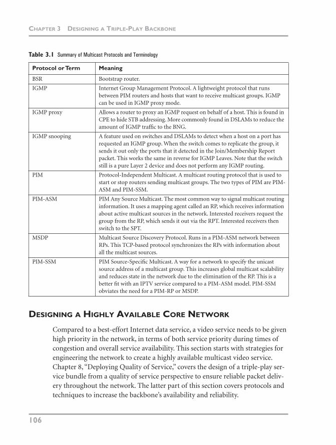
CHAPTER 3 DESIGNING A TRIPLE-PLAY BACKBONE
106
Table 3.1 Summary of Multicast Protocols and Terminology
DESIGNING A HIGHLY AVAILABLE CORE NETWORK
Compared to a best-effort Internet data service, a video service needs to be given high priority in the network, in terms of both service priority during times of congestion and overall service availability. This section starts with strategies for engineering the network to create a highly available multicast video service. Chapter 8, “Deploying Quality of Service,” covers the design of a triple-play ser-vice bundle from a quality of service perspective to ensure reliable packet deliv-ery throughout the network. The latter part of this section covers protocols and techniques to increase the backbone’s availability and reliability.
Protocol or Term Meaning
BSR Bootstrap router.
IGMP Internet Group Management Protocol. A lightweight protocol that runs between PIM routers and hosts that want to receive multicast groups. IGMP can be used in IGMP proxy mode.
IGMP proxy Allows a router to proxy an IGMP request on behalf of a host. This is found in CPE to hide STB addressing. More commonly found in DSLAMs to reduce the amount of IGMP traffic to the BNG.
IGMP snooping A feature used on switches and DSLAMs to detect when a host on a port has requested an IGMP group. When the switch comes to replicate the group, it sends it out only the ports that it detected in the Join/Membership Report packet. This works the same in reverse for IGMP Leaves. Note that the switch still is a pure Layer 2 device and does not perform any IGMP routing.
PIM Protocol-Independent Multicast. A multicast routing protocol that is used to start or stop routers sending multicast groups. The two types of PIM are PIM-ASM and PIM-SSM.
PIM-ASM PIM Any Source Multicast. The most common way to signal multicast routing information. It uses a mapping agent called an RP, which receives information about active multicast sources in the network. Interested receivers request the group from the RP, which sends it out via the RPT. Interested receivers then switch to the SPT.
MSDP Multicast Source Discovery Protocol. Runs in a PIM-ASM network between RPs. This TCP-based protocol synchronizes the RPs with information about all the multicast sources.
PIM-SSM PIM Source-Specific Multicast. A way for a network to specify the unicast source address of a multicast group. This increases global multicast scalability and reduces state in the network due to the elimination of the RP. This is a better fit with an IPTV service compared to a PIM-ASM model. PIM-SSM obviates the need for a PIM-RP or MSDP.
06_Hellberg_ch03.fm Page 106 Monday, April 9, 2007 12:36 PM
DESIGNING A HIGHLY AVAILABLE CORE NETWORK
107
USING MULTIPLE INJECTION POINTS WITH A SINGLE SOURCE ADDRESS
If a single media server is used, all the network redundancy in the world would not help if the single server needs to be rebooted or crashes. Luckily, a single media server deployment is an uncommon occurrence, so the next question is how to run these servers to reduce the downtime when one fails or needs to be bought down for maintenance reasons.
An STB can receive one multicast video channel from a single source at a time. If a server fails, either the network or the STB needs to switch to an alternate source. In current deployments, it is not common for STBs to be able to switch to an alter-native source. One minor point is that such a scenario would require IGMP ver-sion 3, because this protocol can include the group’s source address. Therefore, deployments today need the end-to-end architecture to be robust enough to with-stand server failure, a component of the core transport network, and as much of the PoP hardware as possible. Of course, the closer the network is to the customer, the more expensive it becomes to offer full redundancy.
Multiple video injection points can be used by dedicating a server (or server clus-ter) to one or more edge routers. An active server transmits all the multicast groups to the routers, but only one of these routers actually forwards the traffic to the network, because the downstream routers choose only a single path to the source address when the PIM Join is sent upstream. The injection servers need to share the same source IP address, because the STBs (or BNGs with PIM-SSM mapping) usually have only a single address configured for a given multicast group. The trick is to configure each router interface that connects to a server/server cluster to be configured with the same network address. This creates an anycast domain and functions similar to anycast RP. Each PIM receiver router chooses the lowest-cost route to send the PIM Join message. Each router inter-face has a common network configured for the anycast media servers and announces this to the IGP routing domain. Recall that RPF checks are performed throughout the network on multicast packets to ensure that traffic is coming from the shortest path back to the source. In this case, each router has multiple entries in its routing table back to the traffic source, so it chooses whichever route is the least-cost back to the source.
06_Hellberg_ch03.fm Page 107 Monday, April 9, 2007 12:36 PM
CHAPTER 3 DESIGNING A TRIPLE-PLAY BACKBONE
108
But a more important point and one that is more fundamental to the high-avail-ability architecture is that only one server from a cluster should transmit a group at a time. If all servers were on a common LAN and more than one stream for a group is sent, the edge router would simply forward all packets for the group down the PIM tree, creating interleaved streams. Even though they may be for the same channel, only a single IP stream should be delivered to a client. Vendors delivering such a video solution have techniques to ensure synchronicity between the servers so that only one transmits at a time.
HIGHLY AVAILABLE ROUTING AND SIGNALING PROTOCOLS IN THE CORE
In addition to a highly available video head-end architecture, the underlying pro-tocols, such as MPLS, BGP, and RSVP, also need certain reliability features to ensure that the applications that run on top of the network can assume that the backbone has a strong degree of resilience. This section discusses how various protocols and techniques can be used in the backbone to achieve this.
RSVP
By deploying RSVP-TE LSPs to carry multicast services across the backbone, end-to-end path protection, traffic engineering, and enhanced MPLS QoS can be provided. RSVP can be used to calculate and create a specific path between any two PE routers in the network. The path calculation can be performed offline or using the Constrained Shortest Path First (CSPF) algorithm. It can also be per-formed online and can take into consideration a variety of factors, known as con-straints, to determine the path from the “head-end” to the “tail-end” of the LSP. Traffic enters the LSP at the “head-end” router and leaves the LSP at the “tail- end” router. Path constraints can include bandwidth guarantees, avoiding “dou-ble booking” of a common resource in the network (to make sure a primary and backup path do not traverse the same link or device, for instance).
After this path is created, two examples of how it can be protected are
• Make-before-break secondary path
• Fast reroute link-local protection
06_Hellberg_ch03.fm Page 108 Monday, April 9, 2007 12:36 PM
DESIGNING A HIGHLY AVAILABLE CORE NETWORK
109
Make-Before-Break Secondary Path
By presignaling a “make-before-break” secondary LSP, which does not share any of the same links as the primary path, the head-end router is preseeded with a completely redundant path through the network. When a failure is detected any-where in the LSP, the router directly upstream from the break uses RSVP to sig-nal toward the head-end router that the LSP is no longer usable. As soon as the head-end router receives this message, it tears down the nonworking path and starts forwarding traffic that is destined for the tail end over the secondary path, which was calculated before the failure.
Nondeterministic Failover
RSVP processing, which happens within the control plane of the MPLS routers, can be triggered through a variety of events. Therefore, it is difficult to determin-istically calculate the time required for traffic to be fully restored after a failure. The link failure has to be detected by the local router. Then RSVP can generate and send a notification message toward the head-end router, which also has to be processed. The delay time is at least the propagation delay between the point of the failure and the head-end, plus the time it takes the devices to process the message. In the meantime, the head-end router still forwards traffic down this path, all of which is dropped at the failed link. The greater the bandwidth of the links in the path, the more data that is dropped in front of the failed link.
Fast Reroute Local Protection
With fast reroute, traffic can be rerouted around a link failure more quickly. Each node in the end-to-end path (LSP) can calculate an alternative fast reroute path to the next downstream node to protect traffic during a failure. With fast reroute protection enabled on an LSP, each router in the path calculates an alternative way of getting to the next downstream router. This information can be seeded into the routers’ forwarding plane to make the failover faster. As soon as a link failure is detected, a router can immediately switch traffic for that LSP via the alternative fast reroute path. This allows traffic that is currently in transit to continue to be forwarded along the new path, even while the routers’ control plane is trundling along with the necessary signaling updates. These fast reroute paths can even be constraint-based. Although they can be expensive in terms of processing, features such as fate-sharing, bandwidth guarantees, and other factors can be used when creating the alternative paths. Using these constraints appropriately can allow for nearly seamless end-user experiences, even during a severe network event.
06_Hellberg_ch03.fm Page 109 Monday, April 9, 2007 12:36 PM
CHAPTER 3 DESIGNING A TRIPLE-PLAY BACKBONE
110
Failure Detection
A critical part of restoring a path, using either traditional RSVP signaling or fast reroute, is the initial detection of the link failure. Some transmission media pro-vide signaling and hardware/driver-level notification when the medium becomes unusable (such as SONET/SDH). Other transmission media, such as Ethernet, have no such failure detection capability. Routers typically consist of a variety of integrated components, device drivers that handle specific interface media types, packet processing hardware, and control hardware. Router/vendor implementa-tion and integration of these devices vary from one to the next, so media failure can be detected in a variety of ways. Conceptually, these failures are learned via either “interrupt”-driven events or a “polling” mechanism. Some transmission media are good at being interrupt event-driven. For example, when the protocol detects a SONET/SDH error, a message is sent up the control plane path to notify the rest of the router of the condition. Ethernet media, with no built-in failure detection capabilities, are sometimes left to be polled periodically. In this sce-nario, if a failure happens between polls, it is not detected until the next polling interval.
BFD
Bidirectional Forwarding Detection is a simple forwarding detection protocol that can detect failures from OSI Layer 4 and below. It does this by sending rapid UDP hello packets between two endpoints. These are typically adjacent IGP routing neighbors, but BFD can be extended for use in nearly any conceivable application. Today’s implementations can provide failure response times in the 100 to 120ms range. This rate is improving over time and ultimately aims to pro-vide 50ms failover times.
BFD and Ethernet
One of the most obvious uses of BFD is to provide failure detection for Ethernet media, which have no such inherent mechanism. Without BFD, an IGP adja-cency running over an Ethernet link that experiences a failure would take any-where from seconds to minutes to detect, depending on the timer values. OSPF, by default, would require a loss of three hellos sent at ten-second intervals before flagging a neighbor as down. This would trigger a new OSPF calculation to con-verge around the failed link, giving a failure time of over 30 seconds. Although
06_Hellberg_ch03.fm Page 110 Monday, April 9, 2007 12:36 PM
DESIGNING A HIGHLY AVAILABLE CORE NETWORK
111
these timers can be changed, there are architectural limits to how fast this mech-anism can work. It is possible to increase the IGP hello rates enough to detect a failure in about 3 seconds with OSPF and 1 second with IS-IS, but this places a significant amount of strain on the control plane and typically is avoided. Most common configurations yield standard IGP detection times of 5 to 40 seconds. Using BFD over this same link with a sufficient per-second rate of BFD packets over the link can instead detect the failure in 100 to 120ms.
If BFD functionality (which is being constantly developed in its own IETF work-ing group)7 were to be enabled on the Ethernet, DSLAM, BRAS, and associated elements, rapid failover times could be achieved on these currently vulnerable points.
BFD for MPLS LSPs
BFD in its basic form is used primarily as a hop-by-hop failure detection mecha-nism. A typical core network also requires end-to-end protection. This can be done by extending a BFD session between LSP endpoints and sending rapid hello packets across the entire end-to-end path. Further details can be found in the IETF working group, because the specification was still being worked on at the time of writing.
This section uses several acronyms and terms; they are explained in Table 3.2.
Table 3.2 Summary of Core Protocols
Protocol or Feature Meaning
BFD Bidirectional Forwarding Detection. A lightweight protocol that sends UDP hello packets between two IP addresses. It is used to check a link’s integrity. If a router misses keepalive packets from a remote host, it can consider the link down and can reroute traffic.
Fast reroute A feature that involves presignaling an alternative path for an RSVP-TE LSP so that, if the primary “protected” path fails, traffic can be switched to the standby path with SONET-like speed.
7 http://www.ietf.org/html.charters/bfd-charter.html
continues
06_Hellberg_ch03.fm Page 111 Monday, April 9, 2007 12:36 PM
CHAPTER 3 DESIGNING A TRIPLE-PLAY BACKBONE
112
Integrating Core Protocols with Multicast
The preceding section dealt with the protocols that are used in the core to keep the transport layer in good shape—rapid link failure detection and fast reroute. This section covers the higher-layer protocols and functionality, such as PIM and RPs to provide high-availability multicast signaling. A pure IPv4 multicast core can use either PIM-SSM or PIM-ASM. PIM-ASM requires deploying RPs, so to make this function highly available to the rest of the network, anycast RP is deployed in conjunction with MSDP. Now if one RP in the network goes out of service (planned or unplanned), another RP can take over the role of mapping sources and receivers. Note that in the event of an RP failure, IPTV sessions that are already established between sources and receivers are unaffected. Only new IPTV sessions that need the use of the RP are affected until the network con-verges. PIM-SSM does not need the machinery of the RP, because the mapping function is done either by the BNG doing PIM-SSM group mapping or IGMPv3 from the STB. Although this might seem elegant at first glance, there is a disad-vantage to not having an RP. With PIM-ASM, if a source stops transmitting, the RP eventually deletes this source address (also called [S,G]) from the list of valid sources for the group and switches to a different source for the same group. Nor-mally such a reconvergence takes several seconds while the PIM state times out and works around the failure. This requires that only one media server transmit at one time; otherwise, interleaved streams would result. This allows the network to follow the multicast forwarding state (the RP Joins toward the source that is actually transmitting). With PIM-SSM using an anycast source redundancy
Protocol or Feature Meaning
IGP Interior Gateway Protocol. The internal routing protocol in a network that distributes interface and loopback routes through the service provider domain. The two widespread protocols are IS-IS and OSPF. Both can inter-operate with RSVP using traffic engineering extensions.
LDP Label Distribution Protocol. Used to signal LSPs in an MPLS network. Cre-ating constraints in the LSP is possible using CR-LDP, but generally paths follow the IGP.
MPLS Multiprotocol Label Switching. A way of encapsulating and sending any type of data through a network. It uses the concept of an MPLS label to tell rout-ers where to send the packet.
RSVP-TE Resource Reservation Protocol with Traffic Engineering extensions. Another signaling protocol for LSPs. Can ask the network to reserve bandwidth for the LSP, set constraints on how it is routed, and use link protection.
Table 3.2 continued
06_Hellberg_ch03.fm Page 112 Monday, April 9, 2007 12:36 PM
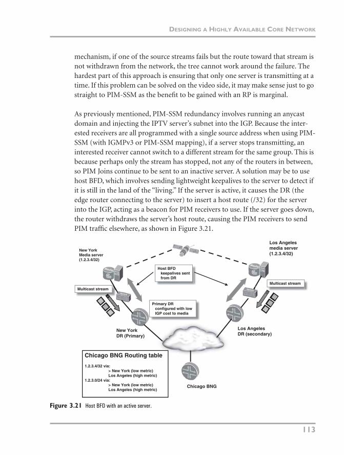
DESIGNING A HIGHLY AVAILABLE CORE NETWORK
113
mechanism, if one of the source streams fails but the route toward that stream is not withdrawn from the network, the tree cannot work around the failure. The hardest part of this approach is ensuring that only one server is transmitting at a time. If this problem can be solved on the video side, it may make sense just to go straight to PIM-SSM as the benefit to be gained with an RP is marginal.
As previously mentioned, PIM-SSM redundancy involves running an anycast domain and injecting the IPTV server’s subnet into the IGP. Because the inter-ested receivers are all programmed with a single source address when using PIM-SSM (with IGMPv3 or PIM-SSM mapping), if a server stops transmitting, an interested receiver cannot switch to a different stream for the same group. This is because perhaps only the stream has stopped, not any of the routers in between, so PIM Joins continue to be sent to an inactive server. A solution may be to use host BFD, which involves sending lightweight keepalives to the server to detect if it is still in the land of the “living.” If the server is active, it causes the DR (the edge router connecting to the server) to insert a host route (/32) for the server into the IGP, acting as a beacon for PIM receivers to use. If the server goes down, the router withdraws the server’s host route, causing the PIM receivers to send PIM traffic elsewhere, as shown in Figure 3.21.
Figure 3.21 Host BFD with an active server.
Multicast streamMulticast stream
Host BFDkeepalives sentfrom DR
New YorkDR (Primary)
Los AngelesDR (secondary)
New YorkMedia server(1.2.3.4/32)
Los Angelesmedia server(1.2.3.4/32)
Chicago BNG
Chicago BNG Routing table
1.2.3.4/32 via:> New York (low metric)Los Angeles (high metric)
1.2.3.0/24 via:> New York (low metric)Los Angeles (high metric)
Primary DRconfigured with lowIGP cost to media
06_Hellberg_ch03.fm Page 113 Monday, April 9, 2007 12:36 PM
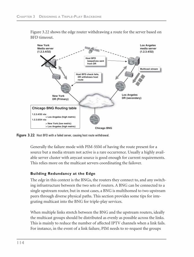
CHAPTER 3 DESIGNING A TRIPLE-PLAY BACKBONE
114
Figure 3.22 shows the edge router withdrawing a route for the server based on BFD timeout.
Figure 3.22 Host BFD with a failed server, causing host route withdrawal.
Generally the failure mode with PIM-SSM of having the route present for a source but a media stream not active is a rare occurrence. Usually a highly avail-able server cluster with anycast source is good enough for current requirements. This relies more on the multicast servers coordinating the failover.
Building Redundancy at the Edge
The edge in this context is the BNGs, the routers they connect to, and any switch-ing infrastructure between the two sets of routers. A BNG can be connected to a single upstream router, but in most cases, a BNG is multihomed to two upstream peers through diverse physical paths. This section provides some tips for inte-grating multicast into the BNG for triple-play services.
When multiple links stretch between the BNG and the upstream routers, ideally the multicast groups should be distributed as evenly as possible across the links. This is mainly to reduce the number of affected IPTV channels when a link fails. For instance, in the event of a link failure, PIM needs to re-request the groups
Multicast stream
New YorkDR (Primary)
Los AngelesDR (secondary)
New YorkMedia server(1.2.3.4/32)
Los Angelesmedia server(1.2.3.4/32)
Chicago BNG
Chicago BNG Routing table
1.2.3.4/32 via:> Los Angeles (high metric)
1.2.3.0/24 via:
> New York (low metric)> Los Angeles (high metric)
Host BFD check fails.DR withdraws hostroute
Host BFDkeepalives sentfrom DR
06_Hellberg_ch03.fm Page 114 Monday, April 9, 2007 12:36 PM
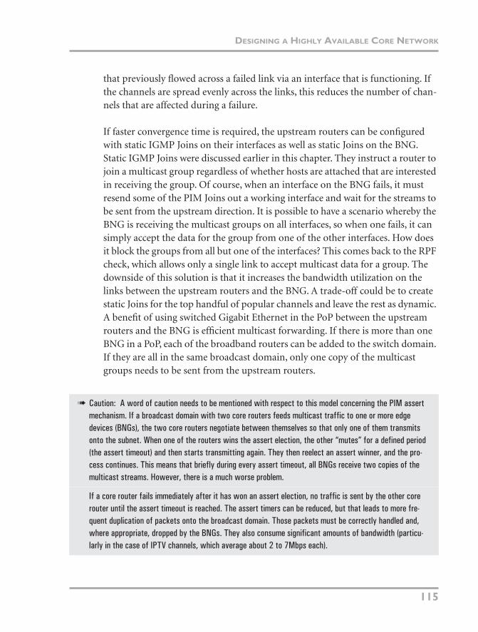
DESIGNING A HIGHLY AVAILABLE CORE NETWORK
115
that previously flowed across a failed link via an interface that is functioning. If the channels are spread evenly across the links, this reduces the number of chan-nels that are affected during a failure.
If faster convergence time is required, the upstream routers can be configured with static IGMP Joins on their interfaces as well as static Joins on the BNG. Static IGMP Joins were discussed earlier in this chapter. They instruct a router to join a multicast group regardless of whether hosts are attached that are interested in receiving the group. Of course, when an interface on the BNG fails, it must resend some of the PIM Joins out a working interface and wait for the streams to be sent from the upstream direction. It is possible to have a scenario whereby the BNG is receiving the multicast groups on all interfaces, so when one fails, it can simply accept the data for the group from one of the other interfaces. How does it block the groups from all but one of the interfaces? This comes back to the RPF check, which allows only a single link to accept multicast data for a group. The downside of this solution is that it increases the bandwidth utilization on the links between the upstream routers and the BNG. A trade-off could be to create static Joins for the top handful of popular channels and leave the rest as dynamic. A benefit of using switched Gigabit Ethernet in the PoP between the upstream routers and the BNG is efficient multicast forwarding. If there is more than one BNG in a PoP, each of the broadband routers can be added to the switch domain. If they are all in the same broadcast domain, only one copy of the multicast groups needs to be sent from the upstream routers.
➠ Caution: A word of caution needs to be mentioned with respect to this model concerning the PIM assert mechanism. If a broadcast domain with two core routers feeds multicast traffic to one or more edge devices (BNGs), the two core routers negotiate between themselves so that only one of them transmits onto the subnet. When one of the routers wins the assert election, the other “mutes” for a defined period (the assert timeout) and then starts transmitting again. They then reelect an assert winner, and the pro-cess continues. This means that briefly during every assert timeout, all BNGs receive two copies of the multicast streams. However, there is a much worse problem.
If a core router fails immediately after it has won an assert election, no traffic is sent by the other core router until the assert timeout is reached. The assert timers can be reduced, but that leads to more fre-quent duplication of packets onto the broadcast domain. Those packets must be correctly handled and, where appropriate, dropped by the BNGs. They also consume significant amounts of bandwidth (particu-larly in the case of IPTV channels, which average about 2 to 7Mbps each).
06_Hellberg_ch03.fm Page 115 Monday, April 9, 2007 12:36 PM
CHAPTER 3 DESIGNING A TRIPLE-PLAY BACKBONE
116
SUMMARY
This chapter has discussed how customers can prepare their network for double-play services that leverage their existing infrastructure, such as MPLS, Layer 2, and Layer 3 VPNs. Layer 3 VPNs can be reused to provide service isolation between different service domains. However, the architecture needs to be planned carefully so that customers can access both service domains at the same time (VoIP and Internet). Sometimes, the concept of separation using VPNs can be taken to an extreme, such that it becomes an inflexible architecture or the ser-vice boundaries become significantly blurred with route leaking. It can be easier to simply have a global routing table for all provider-hosted services, but of course this depends on the provider’s network and how it anticipates building its network. Also it should be considered whether there is the expertise to maintain VPN policy. However, VPNs and the accompanying policy can be a perfectly legitimate model as long as the implications are well-known.
You also saw examples of how multicast can be transported in the core and what routing protocols can be used to set up the correct forwarding state. VPLS cou-pled with P2MP LSPs looks like a promising mechanism as the next step up from point-to-multipoint LSPs for multicast IPTV delivery. Vendors should start sup-porting this delivery method in the future as the IPTV market heats up.
Finally, a highly available multicast IPTV service is a highly desirable feature of triple-play networks, so various approaches were shown, mostly focusing on PIM-SSM anycast deployments and high availability techniques in the core. Any-cast deployment has its drawbacks (such as lack of media stream failure detection in the network), but these generally are addressed by having an intelligent server cluster that can detect media stream failures.
06_Hellberg_ch03.fm Page 116 Monday, April 9, 2007 12:36 PM