Embed Size (px)
Citation preview
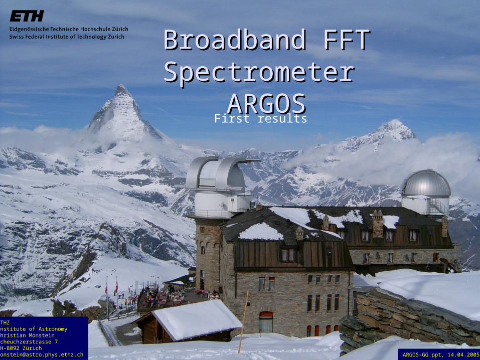
Broadband FFT Spectrometer Broadband FFT Spectrometer
ARGOSARGOSFirst results
ETHZInstitute of Astronomy Christian MonsteinScheuchzerstrasse 7CH-8092 Zü[email protected] ARGOS-GG.ppt, 14.04.2005
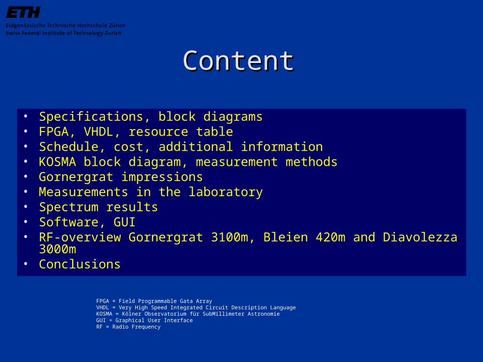
ContentContent
• Specifications, block diagrams• FPGA, VHDL, resource table• Schedule, cost, additional information• KOSMA block diagram, measurement methods • Gornergrat impressions• Measurements in the laboratory• Spectrum results• Software, GUI• RF-overview Gornergrat 3100m, Bleien 420m and Diavolezza 3000m
• Conclusions
FPGA = Field Programmable Gata ArrayVHDL = Very High Speed Integrated Circuit Description LanguageKOSMA = Kölner Observatorium für SubMillimeter AstronomieGUI = Graphical User InterfaceRF = Radio Frequency
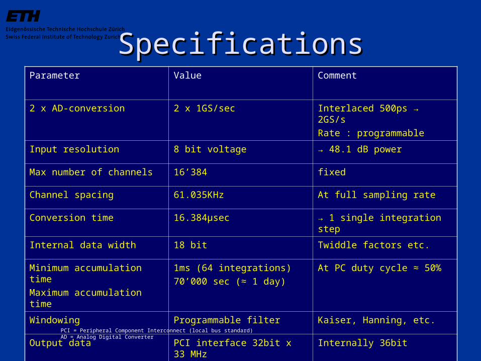
SpecificationsSpecificationsParameter Value Comment
2 x AD-conversion 2 x 1GS/sec Interlaced 500ps → 2GS/s
Rate : programmable
Input resolution 8 bit voltage → 48.1 dB power
Max number of channels 16’384 fixed
Channel spacing 61.035KHz At full sampling rate
Conversion time 16.384µsec → 1 single integration step
Internal data width 18 bit Twiddle factors etc.
Minimum accumulation time
Maximum accumulation time
1ms (64 integrations)
70’000 sec (≈ 1 day)
At PC duty cycle ≈ 50%
Windowing Programmable filter Kaiser, Hanning, etc.
Output data PCI interface 32bit x 33 MHz Internally 36bit
PCI = Peripheral Component Interconnect (local bus standard)AD = Analog Digital Converter
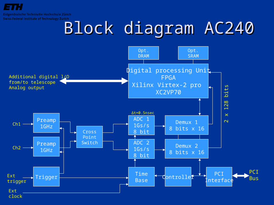
Block diagram AC240Block diagram AC240
Digital processing UnitFPGA
Xilinx Virtex-2 pro XC2VP70
Preamp1GHz
Trigger
CrossPoint
Switch
ADC 11Gs/s8 bit
ADC 21Gs/s8 bit
Demux 18 bits x 16
Demux 28 bits x 16
TimeBase
Preamp1GHz
ControllerPCI
Interface
PCIBus
Opt.DRAM
Opt.SRAM
Additional digital l/Ofrom/to telescopeAnalog output
Ch1
Ch2
Exttrigger
Extclock
2 x
128
bits
Δt=0.5nsec
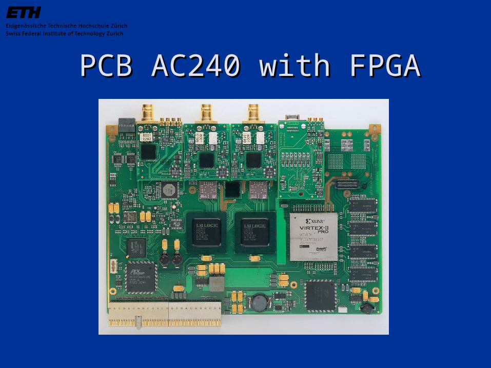
PCB AC240 with FPGAPCB AC240 with FPGA

Block diagram AC240Block diagram AC240
16 k FFTPipeline
complex inputcomplex output
PostProcessing
UnitΣ
j
2 Gs/sreal
even
odd
2 x 1 Gs/sreal
1 Gs/scomplex 1 Gs/s
complex
1 Gs/scomplex
Redundantdata
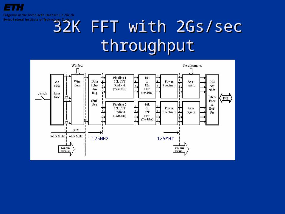
32K FFT with 2Gs/sec throughput32K FFT with 2Gs/sec throughput
125MHz 125MHz

Overview of AC240 FDK coreOverview of AC240 FDK core
D D R C o ntro ller A
WR Buffe r RD Buffe r
DDR SDRAMExte nsio n (512M B)
D ua l Po rt In terfa ce
Dua l Po rt SRAMExte nsio n
Lo c a lBus
M AC 100 M AC 100
Use r-De fine d Pro c e ssing Blo c k
I/O Exte nsio n
Da ta Link
Da ta Link
Trig g e r
D D R C o ntro ller B
WR Buffe r RD Buffe r
DDR SDRAMExte nsio n (512M B)
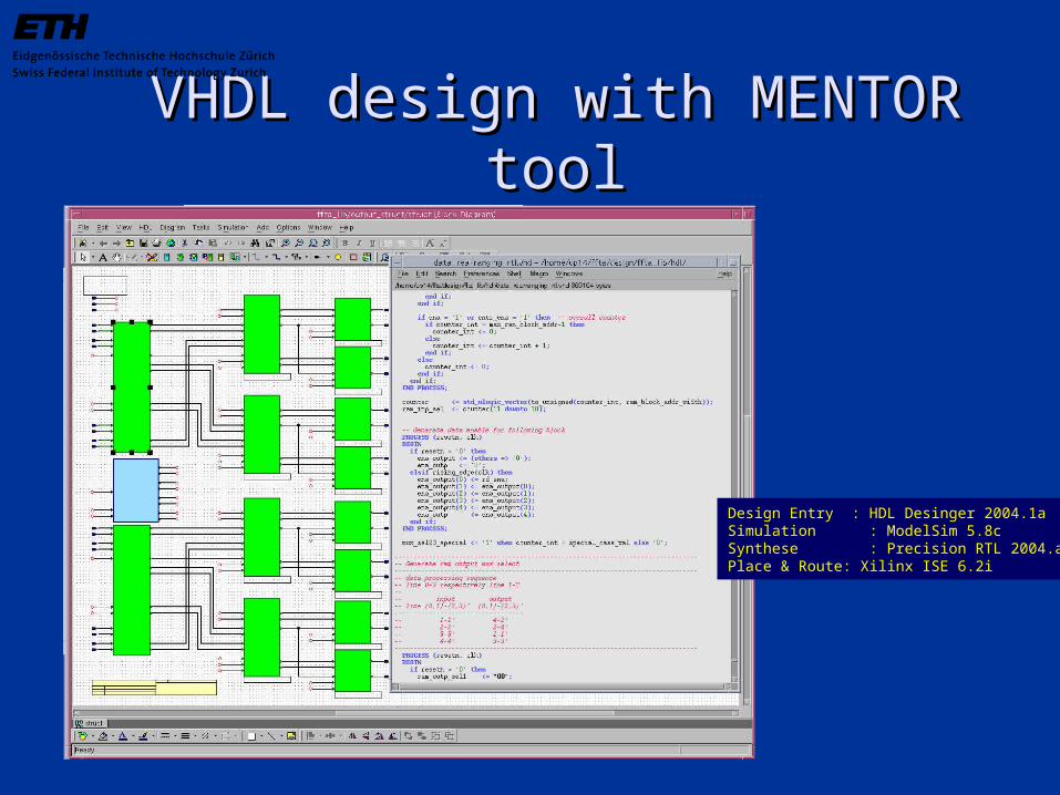
VHDL design with MENTOR toolVHDL design with MENTOR tool
Design Entry : HDL Desinger 2004.1aSimulation : ModelSim 5.8cSynthese : Precision RTL 2004.a1Place & Route: Xilinx ISE 6.2i
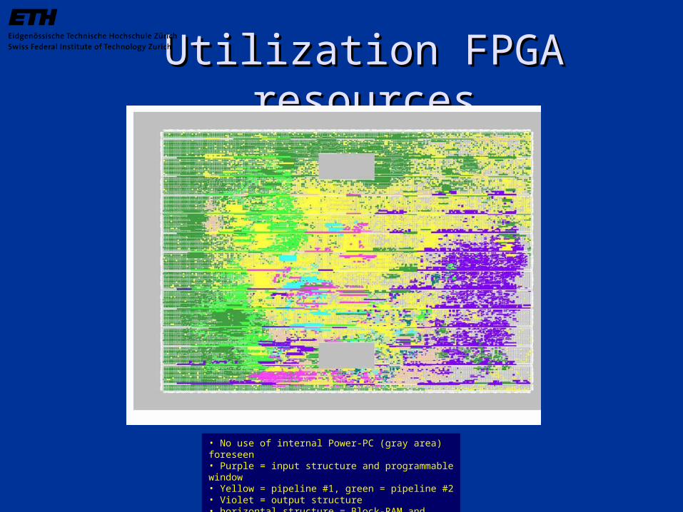
Utilization FPGA resourcesUtilization FPGA resources
• No use of internal Power-PC (gray area) foreseen• Purple = input structure and programmable window• Yellow = pipeline #1, green = pipeline #2• Violet = output structure • horizontal structure = Block-RAM and multipliers
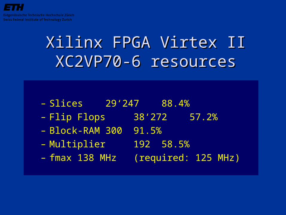
Xilinx FPGA Virtex II XC2VP70-6 Xilinx FPGA Virtex II XC2VP70-6 resourcesresources
– Slices 29‘24788.4%– Flip Flops 38‘27257.2%– Block-RAM 300 91.5%– Multiplier 192 58.5%– fmax 138 MHz (required: 125 MHz)
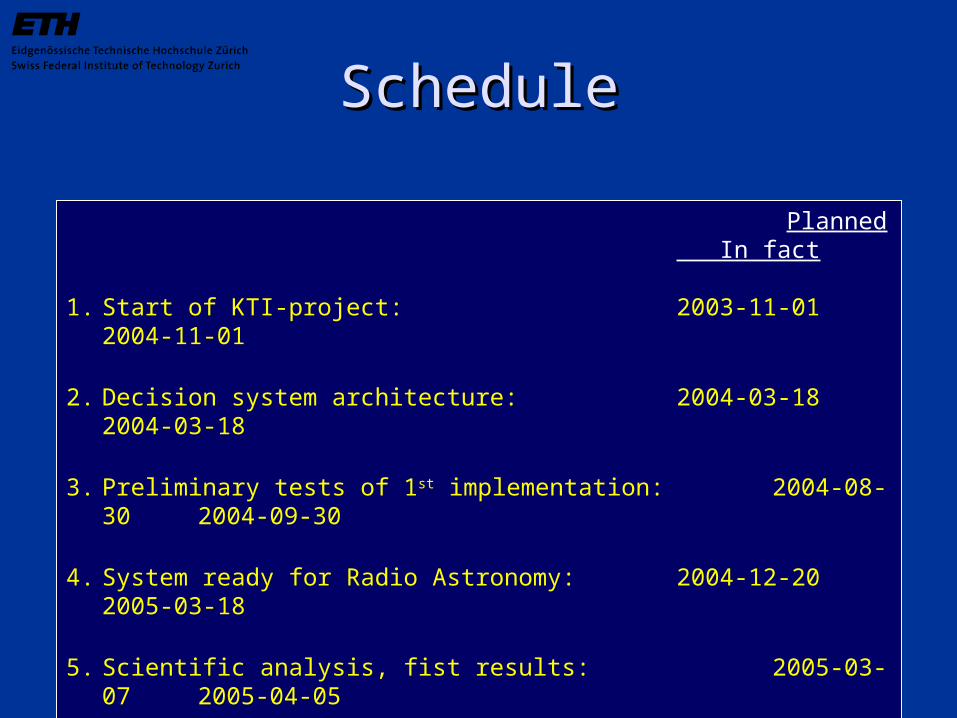
ScheduleSchedule
Planned In fact
1. Start of KTI-project: 2003-11-01 2004-11-
01
2. Decision system architecture: 2004-03-18 2004-03-18
3. Preliminary tests of 1st implementation: 2004-08-30 2004-09-30
4. System ready for Radio Astronomy: 2004-12-20 2005-03-18
5. Scientific analysis, fist results: 2005-03-07 2005-04-05
6. End of project, closing report to KTI: 2005-04-02 2005-05-31
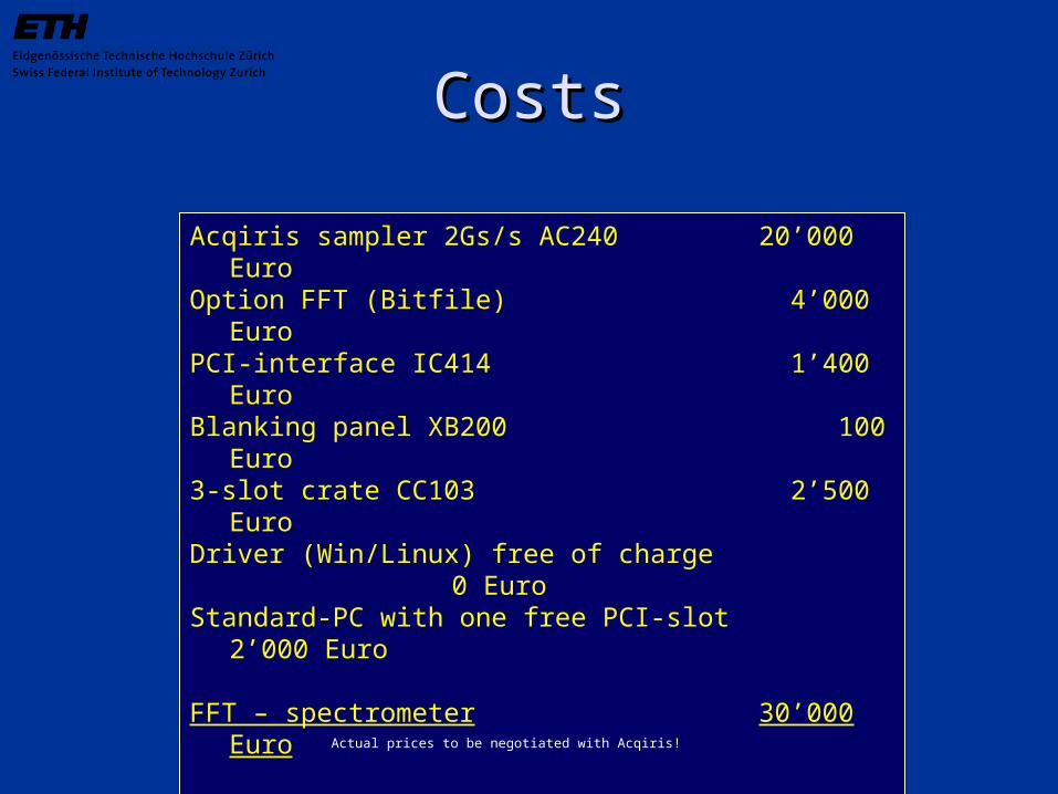
CostsCosts
Acqiris sampler 2Gs/s AC240 20’000 EuroOption FFT (Bitfile) 4’000 EuroPCI-interface IC414 1’400 EuroBlanking panel XB200 100
Euro3-slot crate CC103 2’500 EuroDriver (Win/Linux) free of charge 0
EuroStandard-PC with one free PCI-slot 2’000
Euro
FFT – spectrometer 30’000 Euro
Some statistics to remember….:
1,8 Euro per FFT-channel or33KHz bandwidth for every single Euro
Actual prices to be negotiated with Acqiris!
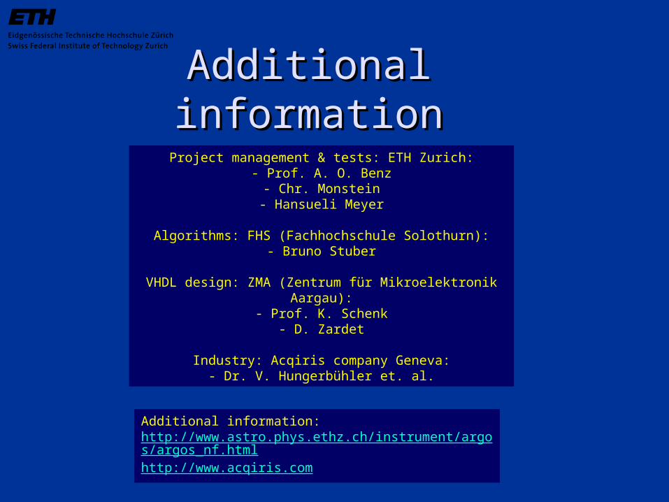
Additional informationAdditional information
Additional information: http://www.astro.phys.ethz.ch/instrument/argos/argos_nf.htmlhttp://www.acqiris.com
Project management & tests: ETH Zurich:- Prof. A. O. Benz- Chr. Monstein
- Hansueli Meyer
Algorithms: FHS (Fachhochschule Solothurn):- Bruno Stuber
VHDL design: ZMA (Zentrum für Mikroelektronik Aargau):- Prof. K. Schenk
- D. Zardet
Industry: Acqiris company Geneva:- Dr. V. Hungerbühler et. al.

Block diagram KOSMABlock diagram KOSMA
Receivers200…900GHz
Local oscillatorunit
Positioningunit
IFunit
AOS LRS1000MHz/1450
AOS MRS300MHz/1800
AOS HRS59MHz/2048
ETH-FFT1GHz/16384
PC Win XPArgos,FTP, VNC
KOSMADSP
KOSMAcontrol
Laptop LINUXIDL
PC Win XPOffice, VNC Printers
ToInternet
Intranet
DigitalI/O -Data ready
-Wobbler controlIF = 350MHz±150MHz
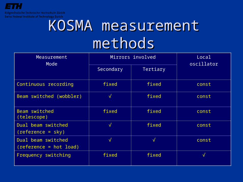
KOSMA measurement methodsKOSMA measurement methodsMeasurement
Mode
Mirrors involved Local
oscillatorSecondary Tertiary
Continuous recording fixed fixed const
Beam switched (wobbler) √ fixed const
Beam switched (telescope) fixed fixed const
Dual beam switched
(reference = sky)
√ fixed const
Dual beam switched
(reference = hot load)
√ √ const
Frequency switching fixed fixed √
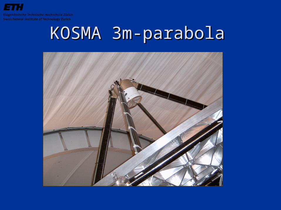
KOSMA 3m-parabolaKOSMA 3m-parabola
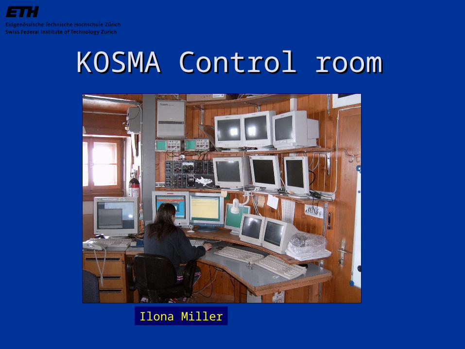
KOSMA Control roomKOSMA Control room
Ilona Miller
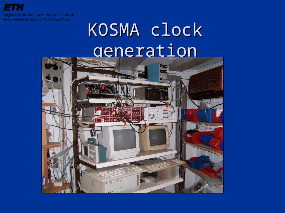
KOSMA clock generationKOSMA clock generation
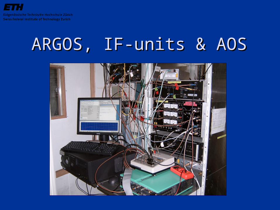
ARGOS, IF-units & AOSARGOS, IF-units & AOS

Allan time hot noise sourceAllan time hot noise source
Data: 3.6 GByte in total,(extraction of Saturday, 02.04.2005.Used for analysis 08:15 - 21:00)FPGA: 52.8°C ±0.2KPlace : Library SECRange: 50mVpp[sec]
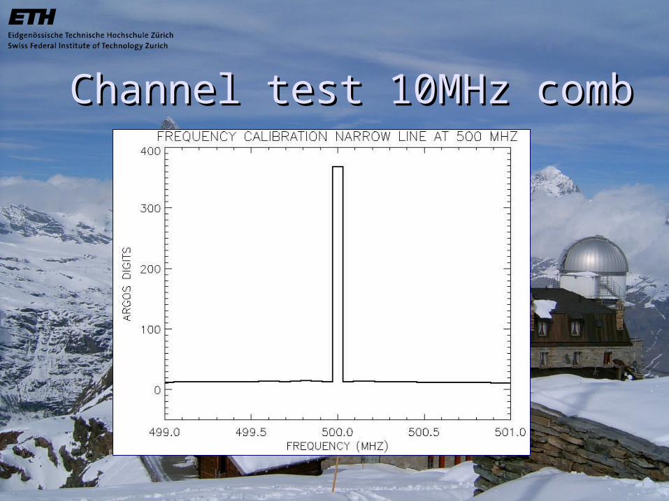
Channel test 10MHz combChannel test 10MHz comb
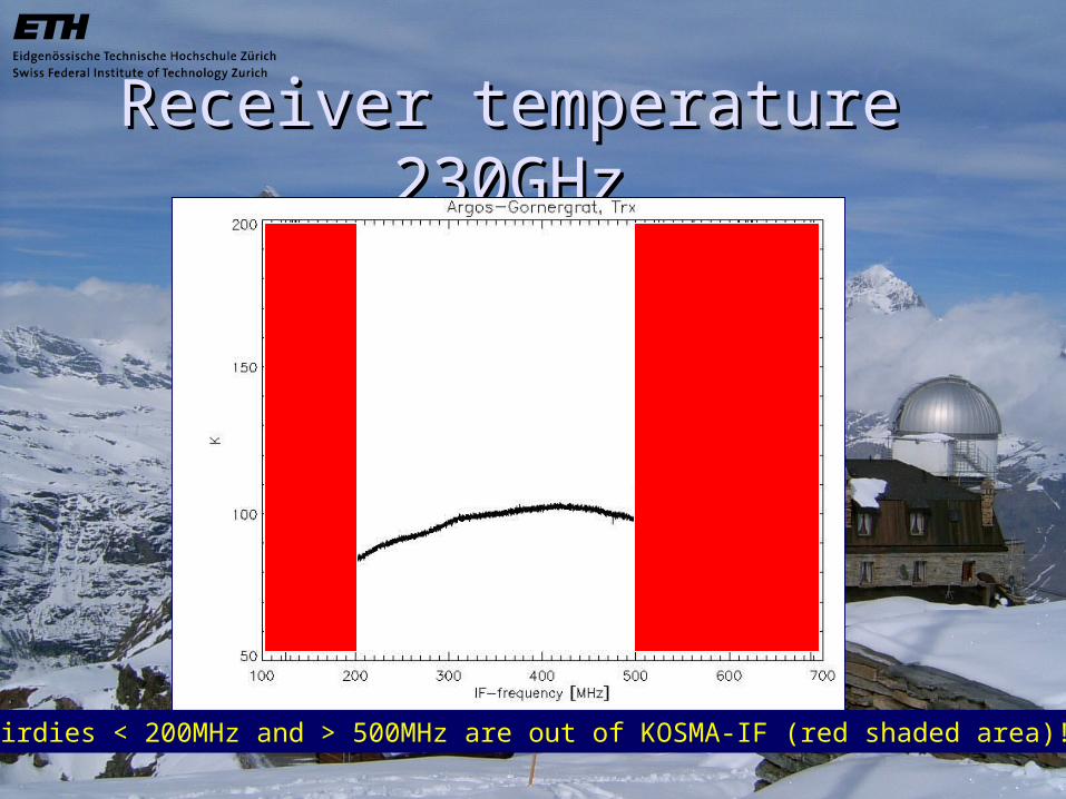
Receiver temperature 230GHzReceiver temperature 230GHz
Birdies < 200MHz and > 500MHz are out of KOSMA-IF (red shaded area)!
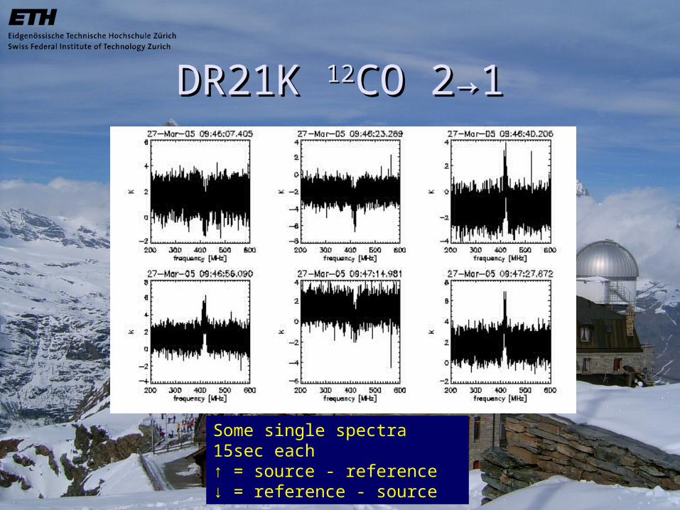
DR21K DR21K 1212CO 2CO 2→→11
Some single spectra 15sec each↑ = source - reference↓ = reference - source
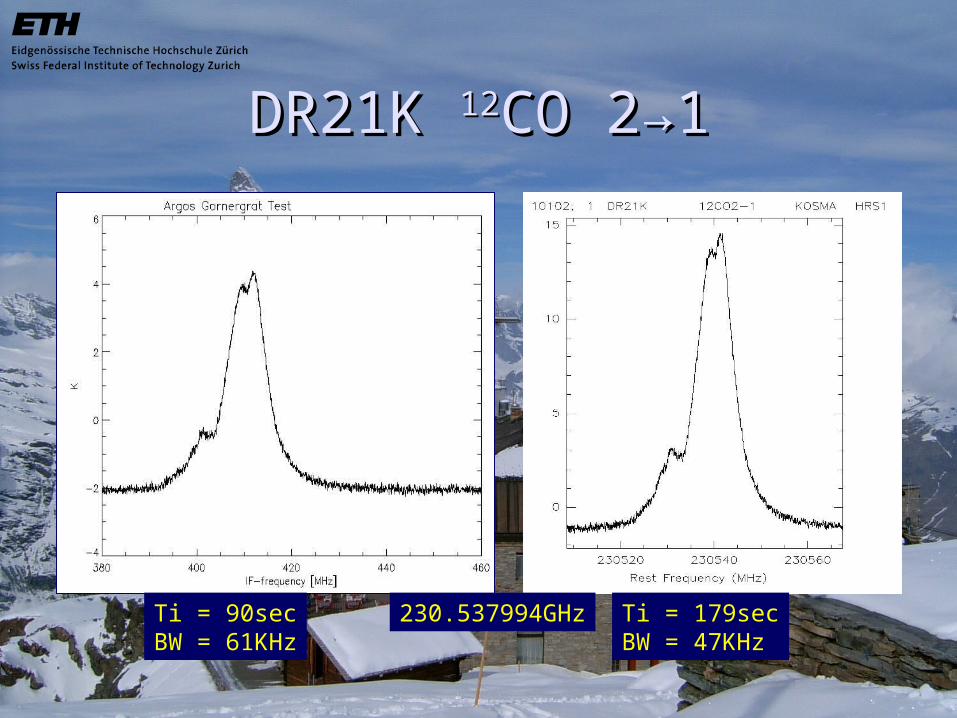
DR21K DR21K 1212CO 2CO 2→→11
230.537994GHz Ti = 179secBW = 47KHz
Ti = 90secBW = 61KHz
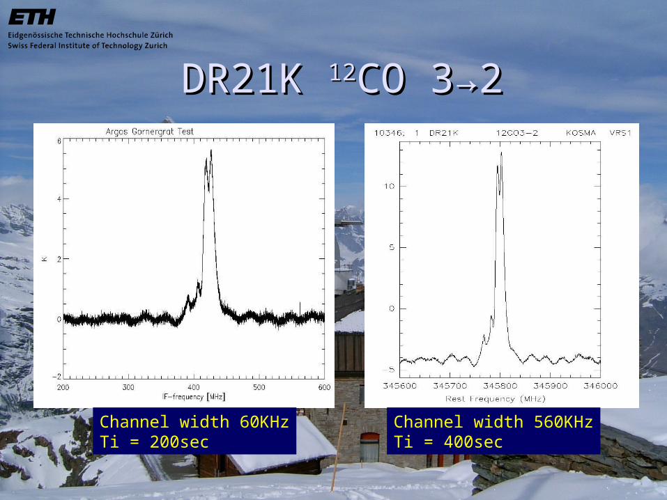
DR21K DR21K 1212CO 3CO 3→→22
Channel width 60KHzTi = 200sec
Channel width 560KHzTi = 400sec

ORION A ORION A 1212CO 2CO 2→→11
Channel width 240KHzTi = 10sec
Channel width 560KHzTi = 20sec
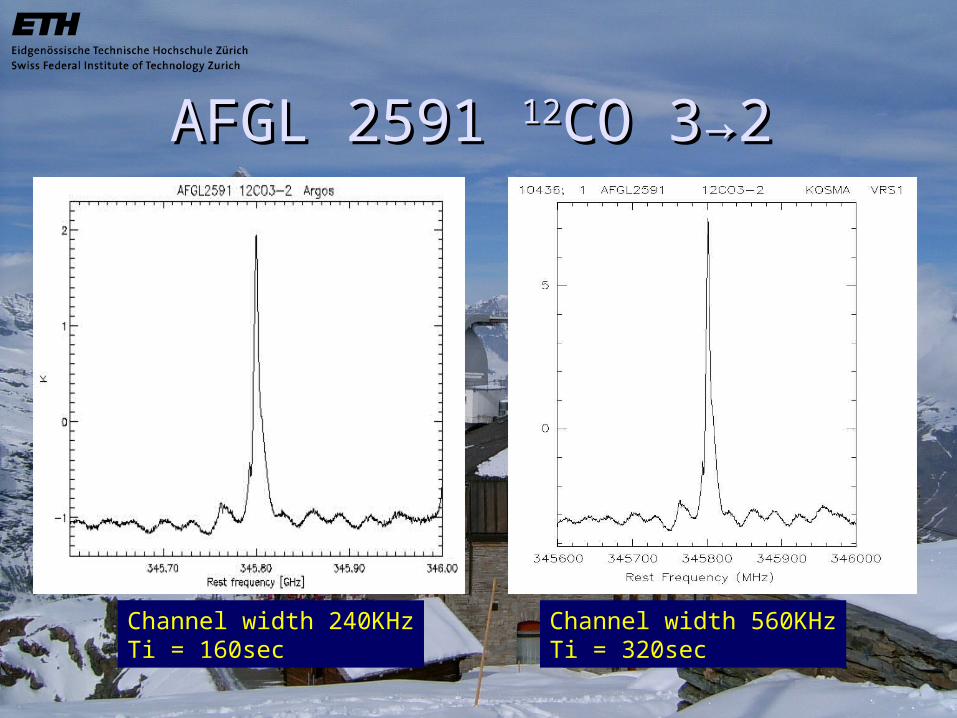
AFGL 2591 AFGL 2591 1212CO 3CO 3→2→2
Channel width 240KHzTi = 160sec
Channel width 560KHzTi = 320sec
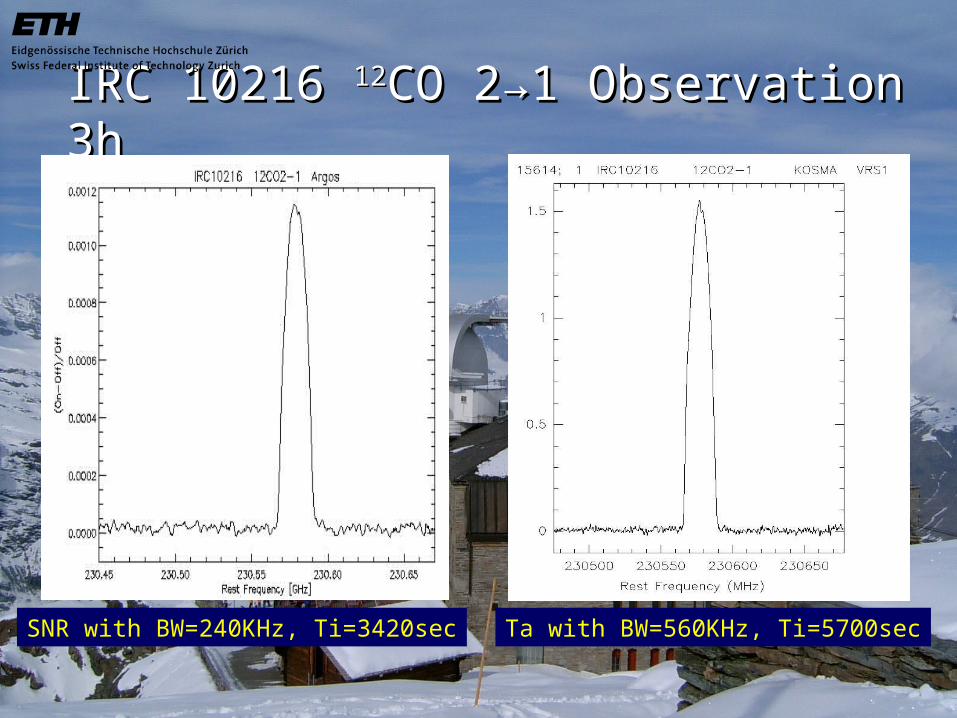
IRC 10216 IRC 10216 1212CO 2CO 2→→1 Observation 3h1 Observation 3h
SNR with BW=240KHz, Ti=3420sec Ta with BW=560KHz, Ti=5700sec
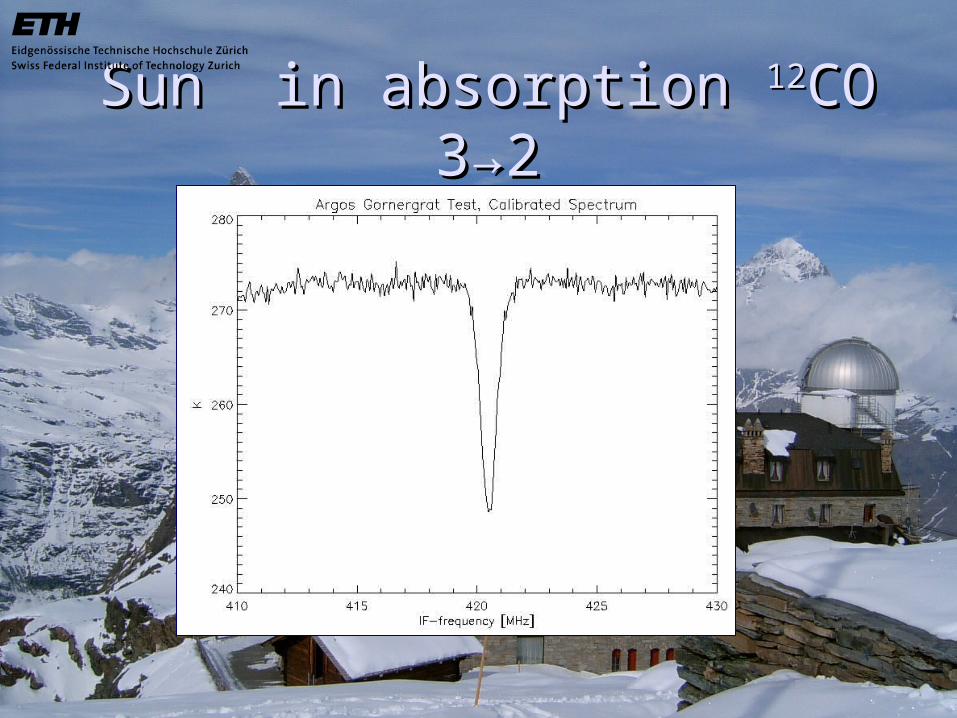
Sun in absorption Sun in absorption 1212CO 3CO 3→→22
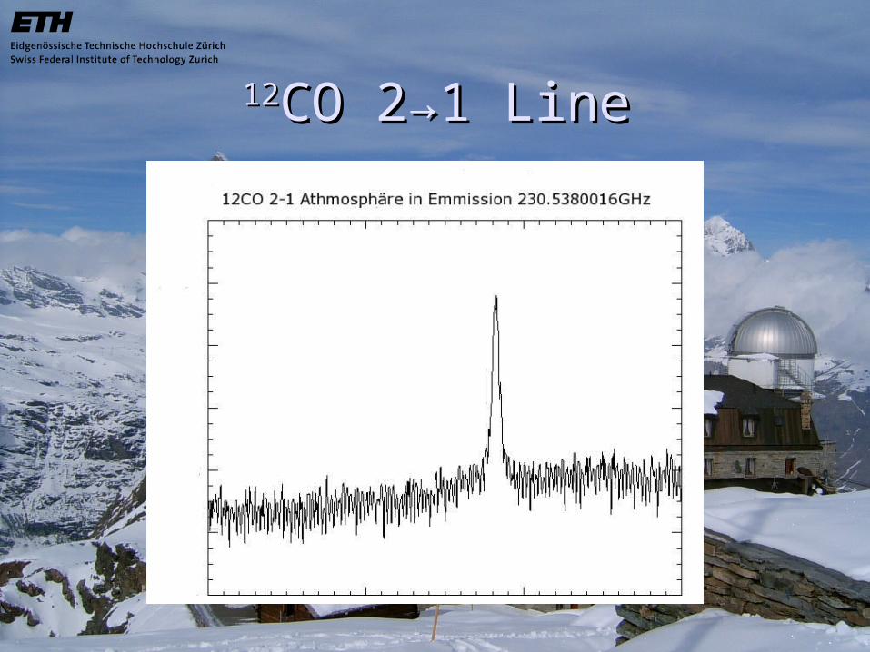
1212CO 2CO 2→→1 Line1 Line
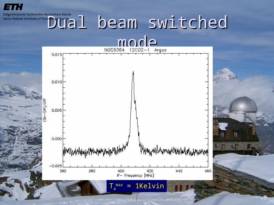
Dual beam switched modeDual beam switched mode
Tamax ≈ 1Kelvin
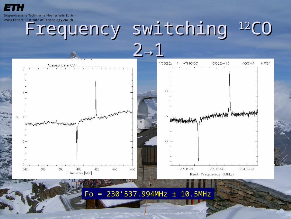
Frequency switching Frequency switching 1212CO 2CO 2→→11
Fo = 230’537.994MHz ± 10.5MHz
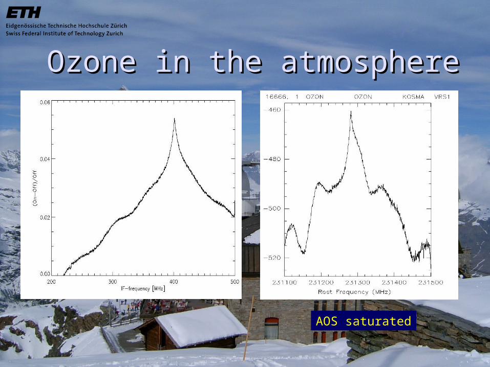
Ozone in the atmosphereOzone in the atmosphere
AOS saturated
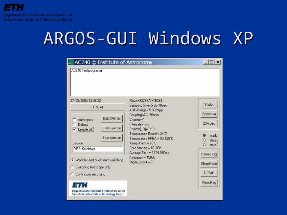
ARGOS-GUI Windows XPARGOS-GUI Windows XP
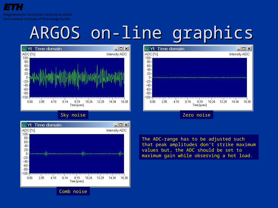
ARGOS on-line graphicsARGOS on-line graphics
Sky noise Zero noise
Comb noise
The ADC-range has to be adjusted suchthat peak amplitudes don’t strike maximumvalues but, the ADC should be set to maximum gain while observing a hot load.
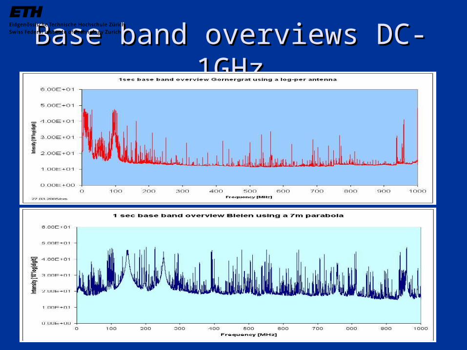
Base band overviews DC-1GHzBase band overviews DC-1GHz
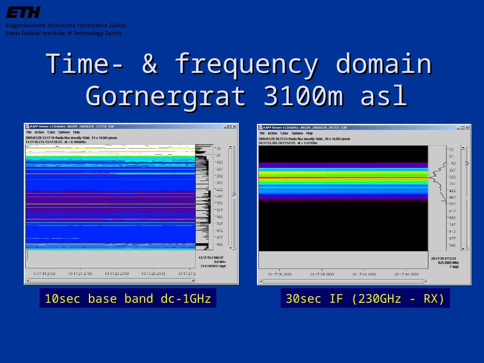
Time- & frequency domain Time- & frequency domain Gornergrat 3100m aslGornergrat 3100m asl
10sec base band dc-1GHz 30sec IF (230GHz - RX)
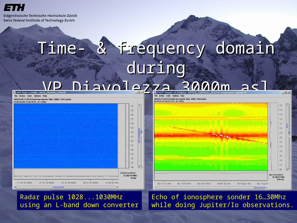
Time- & frequency domain duringTime- & frequency domain duringVP Diavolezza 3000m aslVP Diavolezza 3000m asl
Radar pulse 1028...1030MHzusing an L-band down converter
Echo of ionosphere sonder 16…30Mhzwhile doing Jupiter/Io observations.
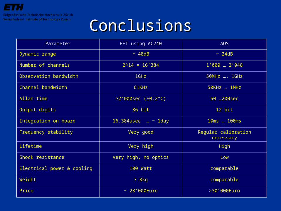
ConclusionsConclusionsParameter FFT using AC240 AOS
Dynamic range ~ 48dB ~ 24dB
Number of channels 2^14 = 16’384 1’000 … 2’048
Observation bandwidth 1GHz 50MHz …. 1GHz
Channel bandwidth 61KHz 50KHz … 1MHz
Allan time >2’000sec (±0.2°C) 50 …200sec
Output digits 36 bit 12 bit
Integration on board 16.384µsec … ~ 1day 10ms … 100ms
Frequency stability Very good Regular calibration necessary
Lifetime Very high High
Shock resistance Very high, no optics Low
Electrical power & cooling 100 Watt comparable
Weight 7.8kg comparable
Price ~ 28’000Euro >30’000Euro