Embed Size (px)
Citation preview
Peter Besant Tel – 07807225801 [email protected] www.prmrp.com
BRL-037/4 Class 37/4
Building Instructions
SCALE MODEL PRODUCT FOR ADULT MODELLERS ONLY. WHITE METAL CONTAINS LEAD WASH HANDS AFTER USE.
MAY CONTAIN SMALL PARTS. ETCHED BRASS HAS FUNCTIONAL SHARP EDGES - HANDLE WITH EXTREME CARE

Thank you for purchasing this kit. This instruction pack should provide an easy to follow guide for building this model given some experience of soldering and the basics of etched kit construction. Drawings and photos are essential for builders to acquaint themselves with the prototype they wish to model. For builders of modern image in 7mm, consider joining MIGO+1, the Modern Image Gauge 0/1 organisation. For more details see the MIGO+1 website at www.migo.org
Soldering Much has been written on the subject of soldering and the basics remain unchanged. Cleanliness, well fluxed, plenty of heat and a good joint should result. After soldering, it is advisable to scrub the model clean using an old toothbrush in a container of warm water and washing up liquid. This will prevent harmful fluxes damaging subsequent surface coatings. Although adhesives may be used to join some parts together, soldering is by far the strongest and neatest way of making this model. Irons. For soldering in the channels or angles, a 75w iron is advisable, which in conjunction with a soldering iron controller ( a dimmer switch is a cheaper alternative) can be used for most of the remaining brass work. One drawback with the 75w is its tip size, and the most common iron in use for 7mm working is the 40w, however for the white metal work a 25w iron should be used. A recent addition is the Resistance Soldering Unit (RSU) which is very useful on the smaller brasswork as it develops localised heat very quickly. Flux. La-Co is a non-corrosive flux for use on most metals including brass or the phosphoric acid/water liquid flux can be used to provide more ‘bite’ if necessary and is particularly effective for white metal. When operating the RSU, solder paint is generally used. Solder. For all general work with nickel silver and brass use electricians multi-core which is available in large reels. For white metal use the 73 degree low-melt variety. As mentioned above, solder paint, which is a combination of flux and solder is effective with the RSU on thin brass overlays and the smaller parts where localised heat is required. Three tips for soldering: a) A damp sponge kept in a plastic margarine (or similar) container is useful for keeping the tip of the iron clean.
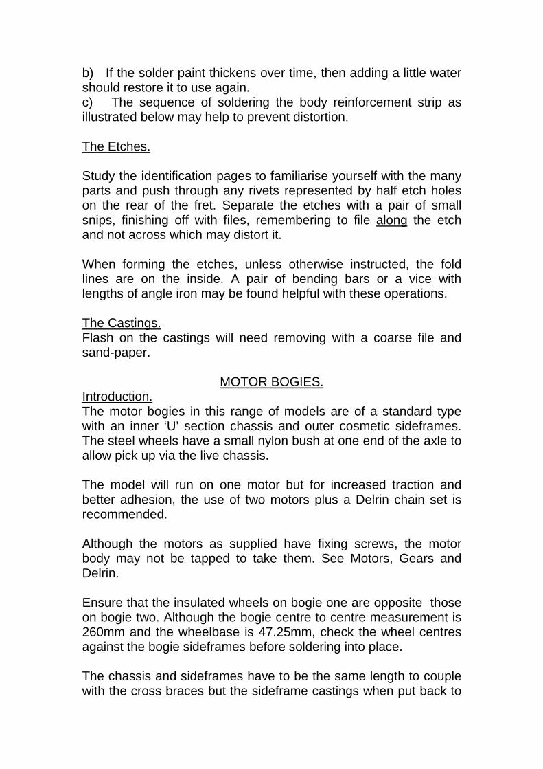
b) If the solder paint thickens over time, then adding a little water should restore it to use again. c) The sequence of soldering the body reinforcement strip as illustrated below may help to prevent distortion. The Etches. Study the identification pages to familiarise yourself with the many parts and push through any rivets represented by half etch holes on the rear of the fret. Separate the etches with a pair of small snips, finishing off with files, remembering to file along the etch and not across which may distort it. When forming the etches, unless otherwise instructed, the fold lines are on the inside. A pair of bending bars or a vice with lengths of angle iron may be found helpful with these operations. The Castings. Flash on the castings will need removing with a coarse file and sand-paper.
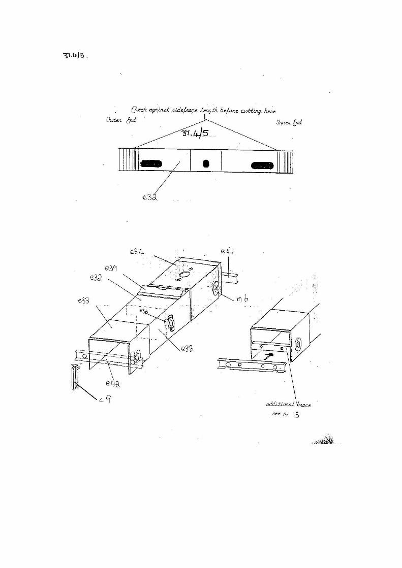
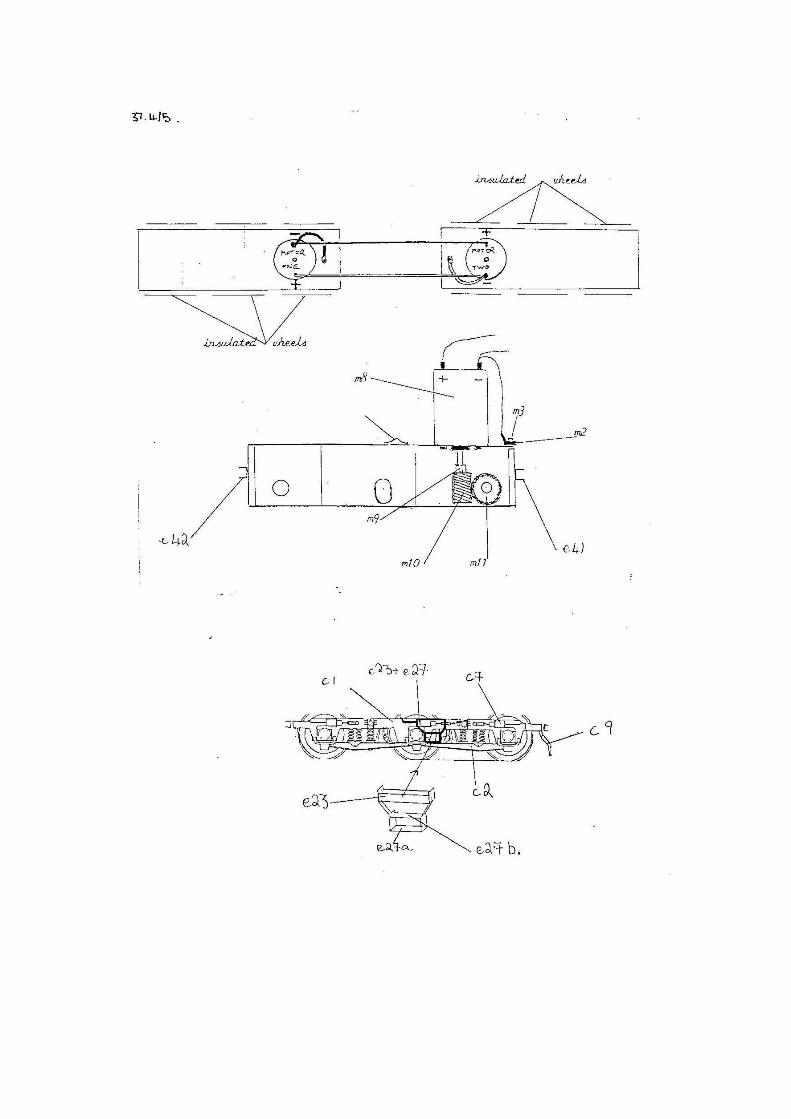
MOTOR BOGIES. Introduction. The motor bogies in this range of models are of a standard type with an inner ‘U’ section chassis and outer cosmetic sideframes. The steel wheels have a small nylon bush at one end of the axle to allow pick up via the live chassis. The model will run on one motor but for increased traction and better adhesion, the use of two motors plus a Delrin chain set is recommended. Although the motors as supplied have fixing screws, the motor body may not be tapped to take them. See Motors, Gears and Delrin. Ensure that the insulated wheels on bogie one are opposite those on bogie two. Although the bogie centre to centre measurement is 260mm and the wheelbase is 47.25mm, check the wheel centres against the bogie sideframes before soldering into place. The chassis and sideframes have to be the same length to couple with the cross braces but the sideframe castings when put back to
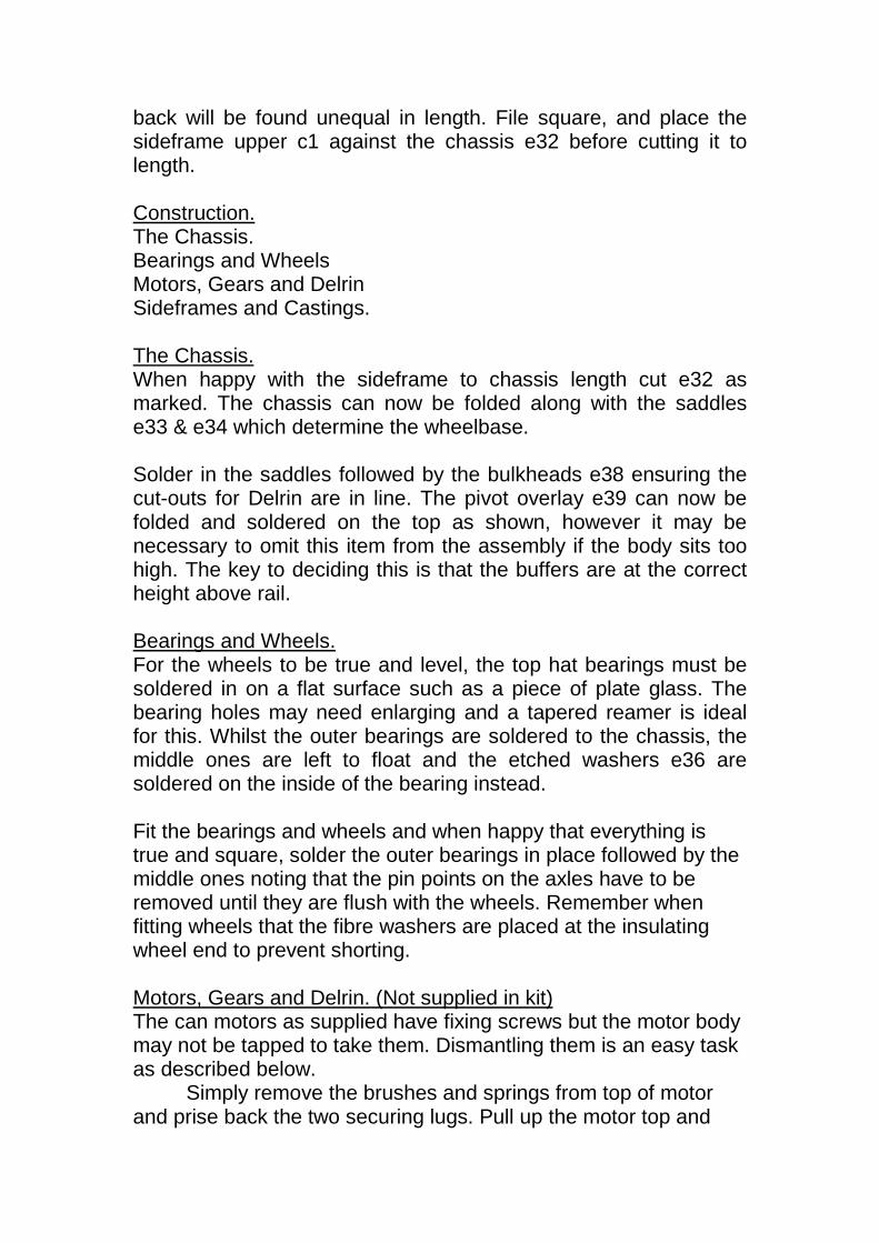
back will be found unequal in length. File square, and place the sideframe upper c1 against the chassis e32 before cutting it to length. Construction. The Chassis. Bearings and Wheels Motors, Gears and Delrin Sideframes and Castings. The Chassis. When happy with the sideframe to chassis length cut e32 as marked. The chassis can now be folded along with the saddles e33 & e34 which determine the wheelbase. Solder in the saddles followed by the bulkheads e38 ensuring the cut-outs for Delrin are in line. The pivot overlay e39 can now be folded and soldered on the top as shown, however it may be necessary to omit this item from the assembly if the body sits too high. The key to deciding this is that the buffers are at the correct height above rail. Bearings and Wheels. For the wheels to be true and level, the top hat bearings must be soldered in on a flat surface such as a piece of plate glass. The bearing holes may need enlarging and a tapered reamer is ideal for this. Whilst the outer bearings are soldered to the chassis, the middle ones are left to float and the etched washers e36 are soldered on the inside of the bearing instead.
Fit the bearings and wheels and when happy that everything is true and square, solder the outer bearings in place followed by the middle ones noting that the pin points on the axles have to be removed until they are flush with the wheels. Remember when fitting wheels that the fibre washers are placed at the insulating wheel end to prevent shorting. Motors, Gears and Delrin. (Not supplied in kit) The can motors as supplied have fixing screws but the motor body may not be tapped to take them. Dismantling them is an easy task as described below.
Simply remove the brushes and springs from top of motor and prise back the two securing lugs. Pull up the motor top and
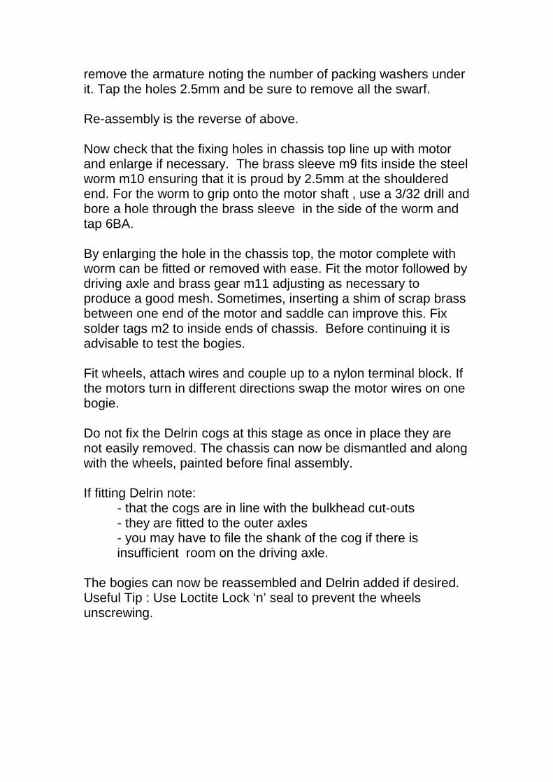
remove the armature noting the number of packing washers under it. Tap the holes 2.5mm and be sure to remove all the swarf. Re-assembly is the reverse of above. Now check that the fixing holes in chassis top line up with motor and enlarge if necessary. The brass sleeve m9 fits inside the steel worm m10 ensuring that it is proud by 2.5mm at the shouldered end. For the worm to grip onto the motor shaft , use a 3/32 drill and bore a hole through the brass sleeve in the side of the worm and tap 6BA. By enlarging the hole in the chassis top, the motor complete with worm can be fitted or removed with ease. Fit the motor followed by driving axle and brass gear m11 adjusting as necessary to produce a good mesh. Sometimes, inserting a shim of scrap brass between one end of the motor and saddle can improve this. Fix solder tags m2 to inside ends of chassis. Before continuing it is advisable to test the bogies. Fit wheels, attach wires and couple up to a nylon terminal block. If the motors turn in different directions swap the motor wires on one bogie. Do not fix the Delrin cogs at this stage as once in place they are not easily removed. The chassis can now be dismantled and along with the wheels, painted before final assembly. If fitting Delrin note: - that the cogs are in line with the bulkhead cut-outs - they are fitted to the outer axles
- you may have to file the shank of the cog if there is insufficient room on the driving axle.
The bogies can now be reassembled and Delrin added if desired. Useful Tip : Use Loctite Lock ‘n’ seal to prevent the wheels unscrewing.
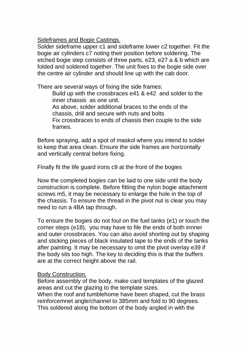
Sideframes and Bogie Castings. Solder sideframe upper c1 and sideframe lower c2 together. Fit the bogie air cylinders c7 noting their position before soldering. The etched bogie step consists of three parts, e23, e27 a & b which are folded and soldered together. The unit fixes to the bogie side over the centre air cylinder and should line up with the cab door. There are several ways of fixing the side frames:
Build up with the crossbraces e41 & e42 and solder to the inner chassis as one unit. As above, solder additional braces to the ends of the chassis, drill and secure with nuts and bolts Fix crossbraces to ends of chassis then couple to the side frames.
Before spraying, add a spot of maskol where you intend to solder to keep that area clean. Ensure the side frames are horizontally and vertically central before fixing. Finally fit the life guard irons c9 at the front of the bogies Now the completed bogies can be laid to one side until the body construction is complete. Before fitting the nylon bogie attachment screws m5, it may be necessary to enlarge the hole in the top of the chassis. To ensure the thread in the pivot nut is clear you may need to run a 4BA tap through. To ensure the bogies do not foul on the fuel tanks (e1) or touch the corner steps (e18), you may have to file the ends of both innner and outer crossbraces. You can also avoid shorting out by shaping and sticking pieces of black insulated tape to the ends of the tanks after painting. It may be necessary to omit the pivot overlay e39 if the body sits too high. The key to deciding this is that the buffers are at the correct height above the rail. Body Construction. Before assembly of the body, make card templates of the glazed areas and cut the glazing to the template sizes. When the roof and tumblehome have been shaped, cut the brass reinforcemnet angle/channel to 385mm and fold to 90 degrees. This soldered along the bottom of the body angled in with the
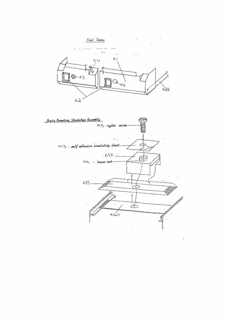
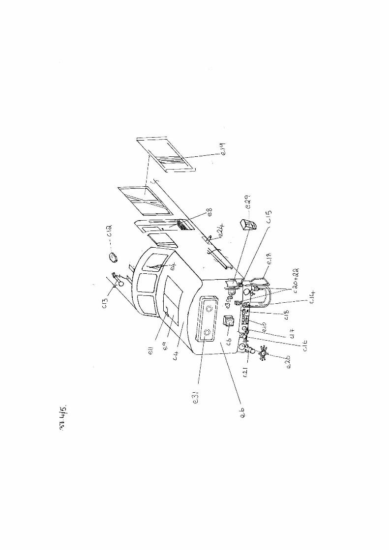
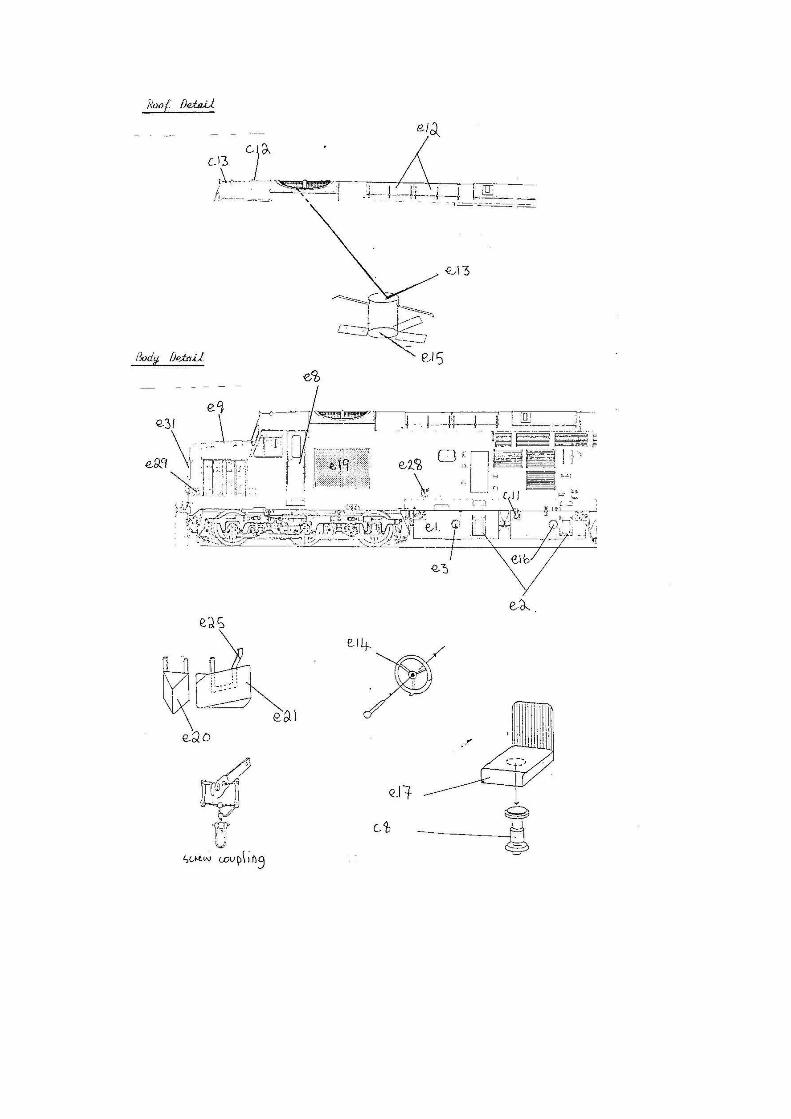
tumblehome. Note that as the body tapers at the ends, both body and angle/channel must be well supported while soldering. Fold up the cab doors e8 noting they are tapered and fit with the door handle to the outside, holes for door handles and hand rails may need opening out as necessary and can be formed from wire provided. Fit the cab doors e8 ensuring the tread plate is level with the cut out in the bodyside. Now fit the handrails and door handles followed the straight sandboxes e28 that fit on the inside of the body. Cut the roof grille mesh, align and solder to the inside of the roof. The fan blades e15 should be bent to 30 degrees and soldered to the fan bracket e13 that has strips on either side that are bent down and out to pass under opposite blades of the fan. Position the complete assembly under the mesh with the ends soldered to each side of the roof. If you wish to paint the fan, leave the assembly off until the model is finished and secure with an epoxy such as Araldite. Fit the radiator grilles e19 centrally behind the bodyside cut-outs folding the shutters to 30 degrees if desired. As previously mentioned the nose sections are tapered, as can be seen by studying the nose castings c4 so allow for this when forming the front panels e6. Align and solder into place adding the castings of the bonnets c4 and windscreens c3, these requiring some gentle shaping and fettling to fit. Laminate by soldering the bogie mounting stretchers e35 and e40 together noting that the sides of e35 are folded up. Solder nut m4 centrally over the hole on the inside of the pivot box e37 then fold and solder this to e35. With the pivot holes in the chassis being off centre, allow for this when fitting completed bogie mounting stretcher assemblies. The wheelbase is 47.25mm and the bogie to bogie measurement is 260mm. Due to limited clearances it is essential to trial fit both completed bogies and fuel tanks before soldering into place. It may also be necessary to file the ends of the bogie crossbraces e41 and e42 to avoid them touching either the fuel tanks or the front steps e18. Fuel Tanks. Form the tanks e1 noting that the small holes are provided to allow the steps e2 to be soldered from behind. Fit the steps e2 and the
tank gauges e3, these fit on the left hand tank with the blank covers e16 on the right. When happy that everything is in place, solder the bogie mounting stretchers between the reinforcing channel, the fuel tanks also locating onto this channel and are supported by the tank stretchers e22. Trim and fold these to 90 degrees before soldering to the tanks. Body Detail. Starting on the roof solder the engine access doors e12 into place, a tip to ensure they fit centrally is to run a pencil line from the middle of the fan opening at one end to cab vent hole at the other end and line up on that. Now fit the cab vents c12 and horns c13 onto cab roof where indicated. Bonnet door hinges e11 fit into recesses in the bonnet doors e9 noting that these will require gentle forming to sit on the nose tops. Using wire provided make blades for the windscreen wipers e4 these fitting under the cab windows. Form the marker light panels e31 and position by locating tabs into slots in the front panel and soldering from behind. Now make wire handrails and fit them, and the lamp brackets e30 where shown. Fold and fit the buffer beam e7 and the corner steps e18 into place. The buffer stocks c10 are drilled out firstly to the diameter of the shank and the to a suitable depth and diameter of Oleo section. For extra support an etched web e26 can be soldered from the inside if desired. The loop on the buffer may need to be carefully drilled out, these being provided to accept a wire passed through the hole in the coupling hook and running to each buffer loop, preventing the heads from revolving. Add the drawbar plate e10, air pipes c18, vac pipes c17, mu fittings c14, c15 & c16 and eth fittings c20, c21 and c22 where indicated. The rubber piping can now be cut and glued to both mu and eth fittings and if screw couplings are used they are assembled with the spring and split pin behind the buffer beam. Headlamps c6 fit onto the etched squares on the front panels and if using snow ploughs e20 and e21 note that the side ploughs are handed and are fitted to the buffer beams using the U shaped brackets e25 that fit into the half etched recesses on the backs of the ploughs.
The handbrake levers e24 are soldered to cut outs in the bodyside and must be angled out to avoid touching the bogie sideframes and causing an electrical short. The fuel tank filler pipes c11 fit where indicated. Any holes or imperfections can be filled with low melt solder or car body filler (avoid the elastic type as this does not adhere to well to brass). Interior detail can be added by using plasticard for both bulkhead and cab floor and using seat parts c8 and e17. The handbrake wheels e14 are fitted onto the bulkhead by first soldering a pin through the hole in the centre of the wheel and secureing the bulkhead with glue. After painting your model fit the glazing into place with blu-tak and epoxy.
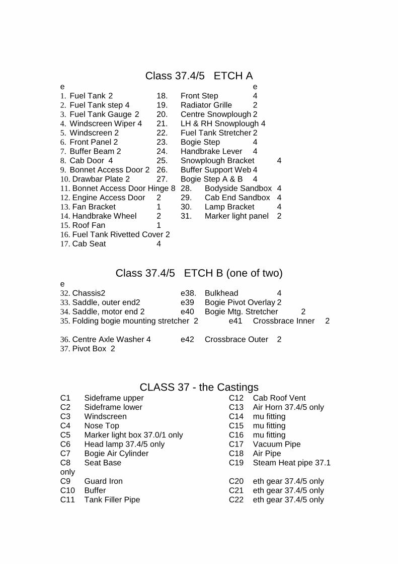
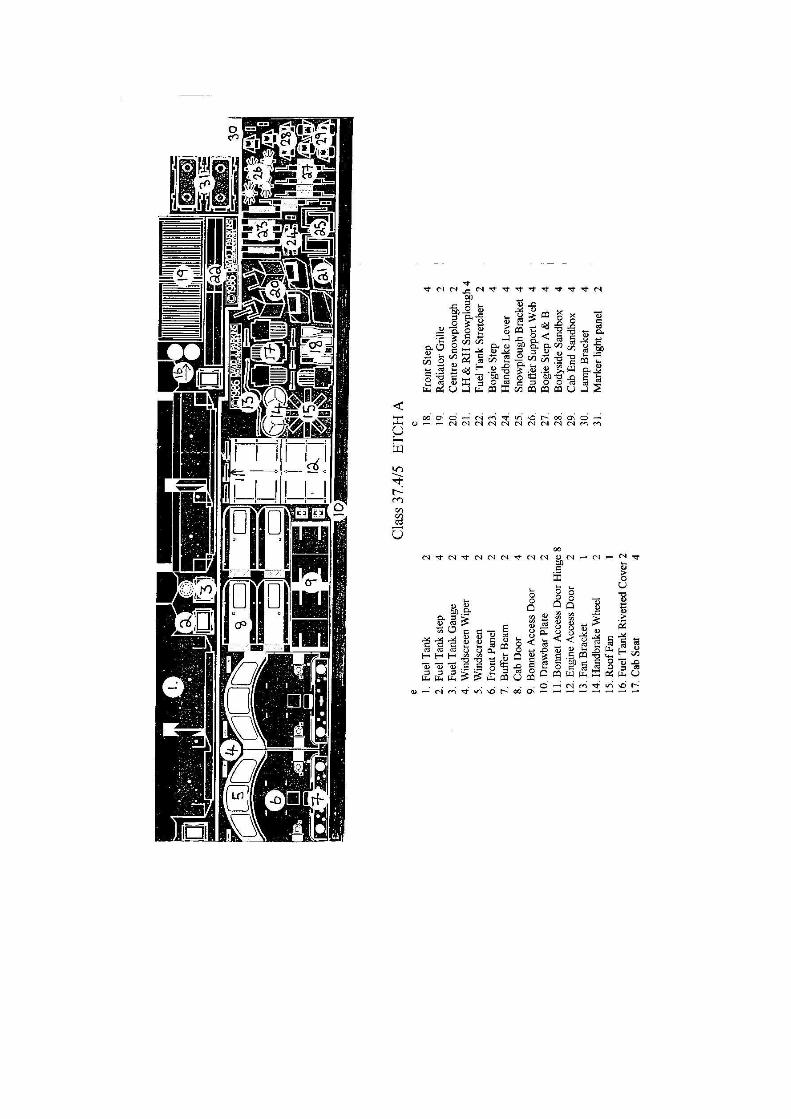
Class 37.4/5 ETCH A e e 1. Fuel Tank 2 18. Front Step 4 2. Fuel Tank step 4 19. Radiator Grille 2 3. Fuel Tank Gauge 2 20. Centre Snowplough 2 4. Windscreen Wiper 4 21. LH & RH Snowplough 4 5. Windscreen 2 22. Fuel Tank Stretcher 2 6. Front Panel 2 23. Bogie Step 4 7. Buffer Beam 2 24. Handbrake Lever 4 8. Cab Door 4 25. Snowplough Bracket 4 9. Bonnet Access Door 2 26. Buffer Support Web 4 10. Drawbar Plate 2 27. Bogie Step A & B 4 11. Bonnet Access Door Hinge 8 28. Bodyside Sandbox 4 12. Engine Access Door 2 29. Cab End Sandbox 4 13. Fan Bracket 1 30. Lamp Bracket 4 14. Handbrake Wheel 2 31. Marker light panel 2 15. Roof Fan 1 16. Fuel Tank Rivetted Cover 2 17. Cab Seat 4
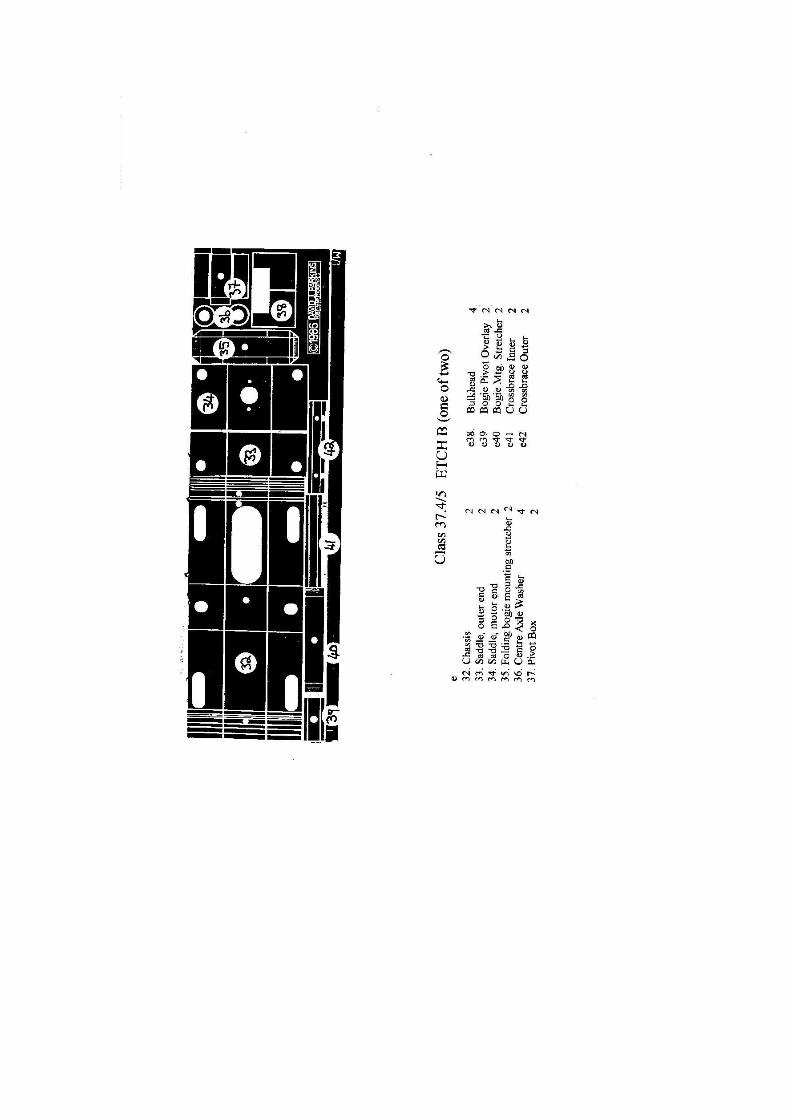
Class 37.4/5 ETCH B (one of two) e 32. Chassis2 e38. Bulkhead 4 33. Saddle, outer end2 e39 Bogie Pivot Overlay 2 34. Saddle, motor end 2 e40 Bogie Mtg. Stretcher 2 35. Folding bogie mounting stretcher 2 e41 Crossbrace Inner 2
36. Centre Axle Washer 4 e42 Crossbrace Outer 2 37. Pivot Box 2
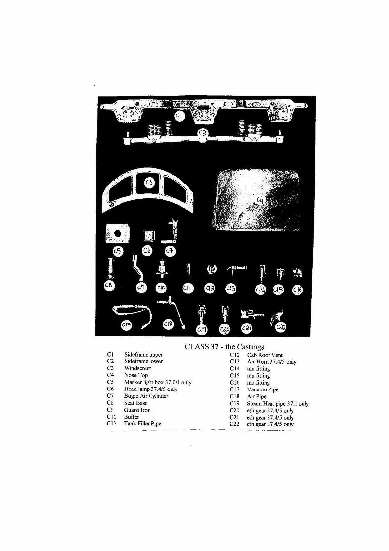
CLASS 37 - the Castings C1 Sideframe upper C12 Cab Roof Vent C2 Sideframe lower C13 Air Horn 37.4/5 only C3 Windscreen C14 mu fitting C4 Nose Top C15 mu fitting C5 Marker light box 37.0/1 only C16 mu fitting C6 Head lamp 37.4/5 only C17 Vacuum Pipe C7 Bogie Air Cylinder C18 Air Pipe C8 Seat Base C19 Steam Heat pipe 37.1 only C9 Guard Iron C20 eth gear 37.4/5 only C10 Buffer C21 eth gear 37.4/5 only C11 Tank Filler Pipe C22 eth gear 37.4/5 only
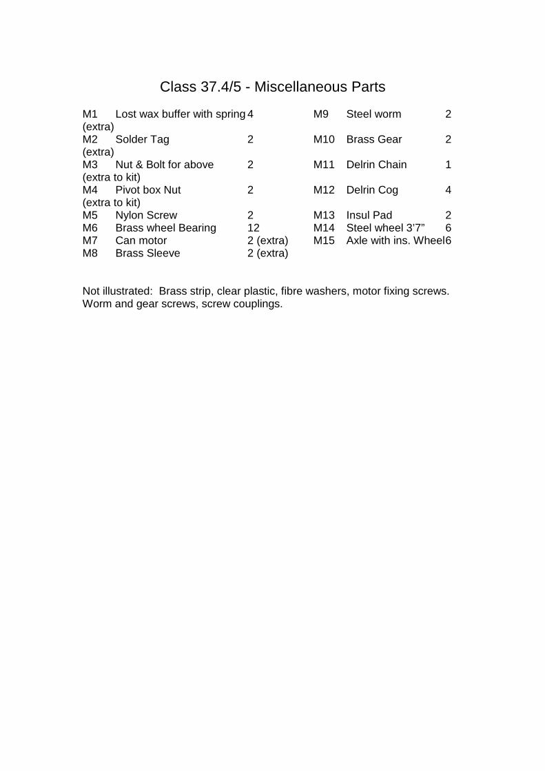
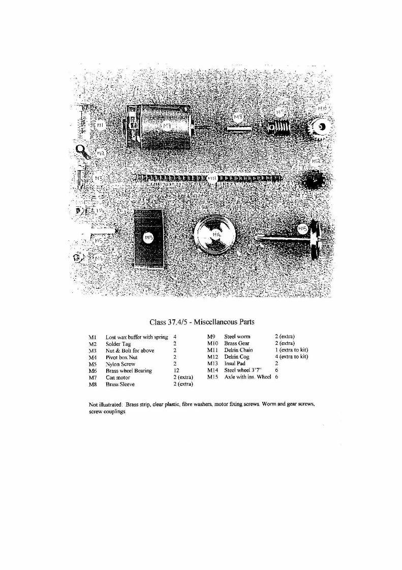
Class 37.4/5 - Miscellaneous Parts M1 Lost wax buffer with spring 4 M9 Steel worm 2 (extra) M2 Solder Tag 2 M10 Brass Gear 2 (extra) M3 Nut & Bolt for above 2 M11 Delrin Chain 1 (extra to kit) M4 Pivot box Nut 2 M12 Delrin Cog 4 (extra to kit) M5 Nylon Screw 2 M13 Insul Pad 2 M6 Brass wheel Bearing 12 M14 Steel wheel 3’7” 6 M7 Can motor 2 (extra) M15 Axle with ins. Wheel 6 M8 Brass Sleeve 2 (extra) Not illustrated: Brass strip, clear plastic, fibre washers, motor fixing screws. Worm and gear screws, screw couplings.