Embed Size (px)
Citation preview
BRITISH MINING No.48
ISSN 0309-2199
BRITISH MINING No.48
MEMOIRS1993
Published by the
THE NORTHERN MINE RESEARCH SOCIETYSHEFFIELD U.K.
© N.M.R.S. & The Author(s) 1993.
Chapman, N.A. 1993“Cleveland Drilling Machines”
British Mining No.48, NMRS, pp.104-127
CLEVELAND DRILLING MACHINES.
by Nigel A. Chapman
SYNOPSISIn the late 19th century, the need to cut unit costs led to experiments in mechanisingthe drilling process. This paper discusses the development of such technology in theCleveland ironstone mining industry in Yorkshire.
INTRODUCTIONDuring the 1830s the removal of nodules of ironstone from the beaches betweenKettleness and Staithes started. Because of the severe weather along this coast, thetransportation by sea to the Tyneside ironworks was a seasonal activity and dependantupon the tide. In 1849 Messrs Bolckow Vaughan began working the Main Seam ofironstone near Skinningrove and shipping this along the coast to their ironworks inCounty Durham, again being very dependent on the weather and the state of the tide.
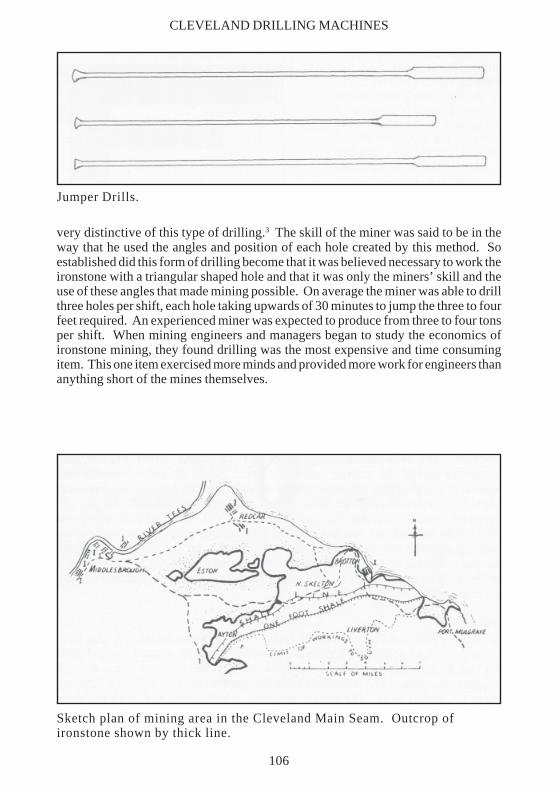
Then, on June 8th 1850, John Marley and John Vaughan discovered the Main Seamof ironstone on the Eston Hills.1 Messrs Bolckow Vaughan quickly took out a leaseof this ironstone and began quarrying operations along the outcrop. As these workingsdeveloped, quarrying gave way to mining, with eventually three major drift entrancesbeing developed on the hillside. Because of the strong links with the Durhamcoalfield, the expertise and mining methods were brought across the River Tees toexploit the Cleveland ironstone and so, from the beginning, the Bord and Pillar formof working became the standard method of extraction, as it was north of the Tees.
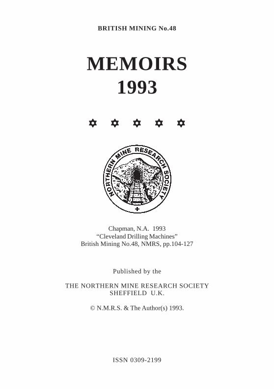
BORD AND PILLARIn the first or ‘Whole’ working,two bords of 14 feet wide weredriven about 40 yards and thesewere linked every 30 yards apartby bords driven at right angles.By this means, pillars of 35 yardsby 25 yards were formed. Thegeneral practice was to drive thebords to the royalty boundarybefore any pillar removal started.2
This meant that these bords stoodunused or unmaintained for years,with all the problems of collapse,before being used again. In lateryears, therefore, the removal ofthe pillars was started about three
Bord and Pillar method ofworking the ironstone.
104
BRITISH MINING No.48
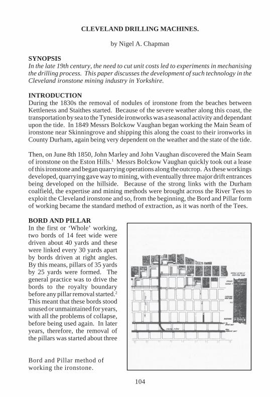
pillars behind the ‘whole’working. In the second stage, or‘broken’ working, the object wasto extract as much of the pillarsas possible. Because of thethickness of the seam, it wasusually necessary to leave abarrier of stone on the ‘goaf’side and to drive all the ‘splits’and ‘lifts’ in the solid pillar.From the illustration, it will beseen that a stepped line of ‘goaf’was used to control the weights,or crush, and to maintain theventilation. The ideal districtwas one of six to eight pillarseach side of the main haulageroad. When a new row of pillarswas to be extracted, a tubway
Extraction of a pillar.
was laid along the bord. If this had collapsed, a heading was driven along the outbyeend of the pillars and ‘spilings’ put through the collapsed bords. These spilings weredriven nine feet wide between timbers and the full height of the seam. Naturally thisredriving added considerably to the cost of working. The illustration shows themethod of extracting a pillar. A split was driven along the outbye side of the pillar,followed by a lift of five yards wide driven at right angles through the pillar. Havingleft a supporting rib two to three yards thick, a further lift was taken through the pillar.After each lift had been driven, the supporting rib was removed. This sequence ofoperations was then repeated. The next operation was to extract the timber. This wasthe most dangerous part of the activity and was carried out by skilled timber-drawers.Assuming that the pillar had been completely extracted, its place would have beentaken by a series of props in rows. These were taken down with the aid of a Sylvester,starting from the area near the goaf. As this work was proceeding, one man would takean axe and cut notches into various props to give an audible warning when the weightcame on to them. This operation was known as ‘Drawing the Jud’. Timber removalwould continue until the roof began to show signs of collapse. It was consideredessential for the jud to close up completely to relieve the other pillars of the weight.
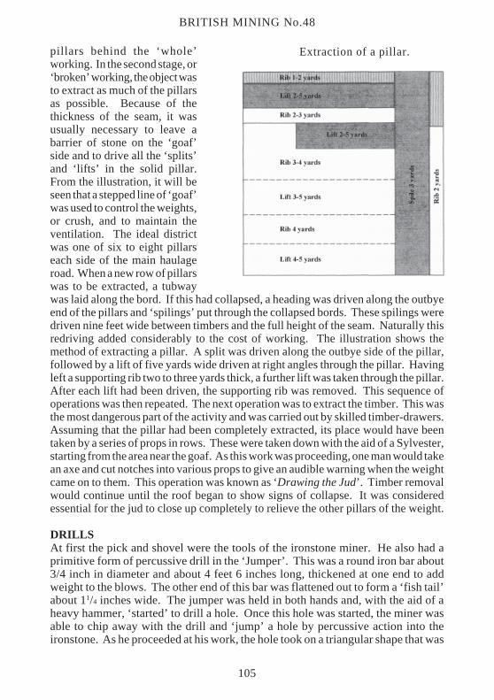
DRILLSAt first the pick and shovel were the tools of the ironstone miner. He also had aprimitive form of percussive drill in the ‘Jumper’. This was a round iron bar about3/4 inch in diameter and about 4 feet 6 inches long, thickened at one end to addweight to the blows. The other end of this bar was flattened out to form a ‘fish tail’about 11/4 inches wide. The jumper was held in both hands and, with the aid of aheavy hammer, ‘started’ to drill a hole. Once this hole was started, the miner wasable to chip away with the drill and ‘jump’ a hole by percussive action into theironstone. As he proceeded at his work, the hole took on a triangular shape that was
105
very distinctive of this type of drilling.3 The skill of the miner was said to be in theway that he used the angles and position of each hole created by this method. Soestablished did this form of drilling become that it was believed necessary to work theironstone with a triangular shaped hole and that it was only the miners’ skill and theuse of these angles that made mining possible. On average the miner was able to drillthree holes per shift, each hole taking upwards of 30 minutes to jump the three to fourfeet required. An experienced miner was expected to produce from three to four tonsper shift. When mining engineers and managers began to study the economics ofironstone mining, they found drilling was the most expensive and time consumingitem. This one item exercised more minds and provided more work for engineers thananything short of the mines themselves.
Sketch plan of mining area in the Cleveland Main Seam. Outcrop ofironstone shown by thick line.
Jumper Drills.
CLEVELAND DRILLING MACHINES
106
BRITISH MINING No.48
EARLY EXPERIMENTSThere were trials of the early hand-operated ratchet drills at the Liverton Mines anda few were also used at the Belmont and Spawood Mines before 1880, but very littleappears to have followed from these trials.4 The French Villepigues drill, a rotaryhand drill complete with a stand, was tested in 1870 at the Normanby Mines of MessrsBell Brothers. It proved to be capable of drilling at the rate of nine inches per minutemaximum.5 Nothing further is heard of this machine and the jumper reigned supreme.
A major problem of the Cleveland ironstone field was that the further from Eston andthe coast that a mine was placed, the thicker became a band of shale in the middle ofthe Main seam. So the seam at Eston Mines was 12 feet of clean stone, but at BrottonMine it was down to 8 feet 4 inches of stone, 2 feet 1 inch of shale and a bottom blockof 2 feet 7 inches of stone. From this it will be realised that not only was there lessironstone to work, but it was also the added problem of the handling and disposal ofa considerable amount of rubbish. The inland mines of Kilton, Liverton, Slapewath,Stanghow etc were at a great disadvantage in production costs when compared to theclean stone coastal mines. In times of depression in the iron trade, these mines withthe shale band were the first to close and in several cases they had very precariouslives. Because of these constraints, when technology was available it was used by the
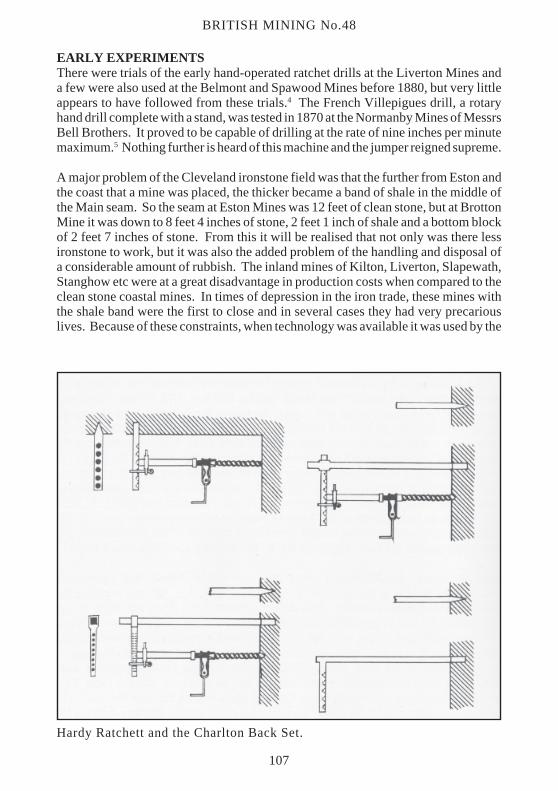
Hardy Ratchett and the Charlton Back Set.
107
‘shale band’ mines, which werethus in the forefront of thedevelopment of this technology.
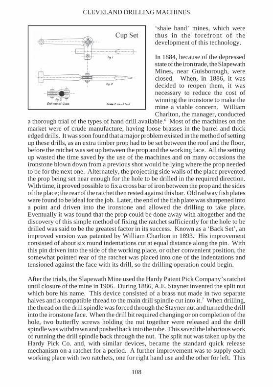
In 1884, because of the depressedstate of the iron trade, the SlapewathMines, near Guisborough, wereclosed. When, in 1886, it wasdecided to reopen them, it wasnecessary to reduce the cost ofwinning the ironstone to make themine a viable concern. WilliamCharlton, the manager, conducted
a thorough trial of the types of hand drill available.6 Most of the machines on themarket were of crude manufacture, having loose brasses in the barrel and thickedged drills. It was soon found that a major problem existed in the method of settingup these drills, as an extra timber prop had to be set between the roof and the floor,before the ratchet was set up between the prop and the working face. All the settingup wasted the time saved by the use of the machines and on many occasions theironstone blown down from a previous shot would be lying where the prop neededto be for the next one. Alternately, the projecting side walls of the place preventedthe prop being set near enough for the hole to be drilled in the required direction.With time, it proved possible to fix a cross bar of iron between the prop and the sidesof the place; the rear of the ratchet then rested against this bar. Old railway fish plateswere found to be ideal for the job. Later, the end of the fish plate was sharpened intoa point and driven into the ironstone and allowed the drilling to take place.Eventually it was found that the prop could be done away with altogether and thediscovery of this simple method of fixing the ratchet sufficiently for the hole to bedrilled was said to be the greatest factor in its success. Known as a ‘Back Set’, animproved version was patented by William Charlton in 1893. His improvementconsisted of about six round indentations cut at equal distance along the pin. Withthis pin driven into the side of the working place, or other convenient position, thesomewhat pointed rear of the ratchet was placed into one of the indentations andtensioned against the face with its drill, so the drilling operation could begin.
After the trials, the Slapewath Mine used the Hardy Patent Pick Company’s ratchetuntil closure of the mine in 1906. During 1886, A.E. Stayner invented the split nutwhich bore his name. This device consisted of a brass nut made in two separatehalves and a compatible thread to the main drill spindle cut into it.7 When drilling,the thread on the drill spindle was forced through the Stayner nut and turned the drillinto the ironstone face. When the drill bit required changing or on completion of thehole, two butterfly screws holding the nut together were released and the drillspindle was withdrawn and pushed back into the tube. This saved the laborious workof running the drill spindle back through the nut. The split nut was taken up by theHardy Pick Co. and, with similar devices, became the standard quick releasemechanism on a ratchet for a period. A further improvement was to supply eachworking place with two ratchets, one for right hand use and the other for left. This
CLEVELAND DRILLING MACHINES
108
BRITISH MINING No.48
permitted the advantage of the weight of the handle plus the pull-down stroke toadvance the drill. Each pair of miners, having been supplied with one of each typeof machine, could use them to best advantage. Having shown what could be donewith the ratchet as against the jumper drill at Slapewath Mine, the machine cameinto more general use in Cleveland, but only after a great deal of opposition from themen and a strike. That, however, is beyond the scope of this paper.
GRAY AND TARBUTT ROTARY HAND DRILLProbably the next improvement was the Gray and Tarbutt machine in which a rotarymotion of the handle was converted at right angles to drive the drill.8 Gray andTarbutt were the manager and engineer at the South Skelton Mine, so this machinewas developed and much used there. Patented in 1893, it was the first successfulrotary ratchet to be in common use. It suffered from problems with the split nutarrangement, however, and this required careful use because the threads were proneto damage. Probably this weakness prevented the more extensive use of themachine.
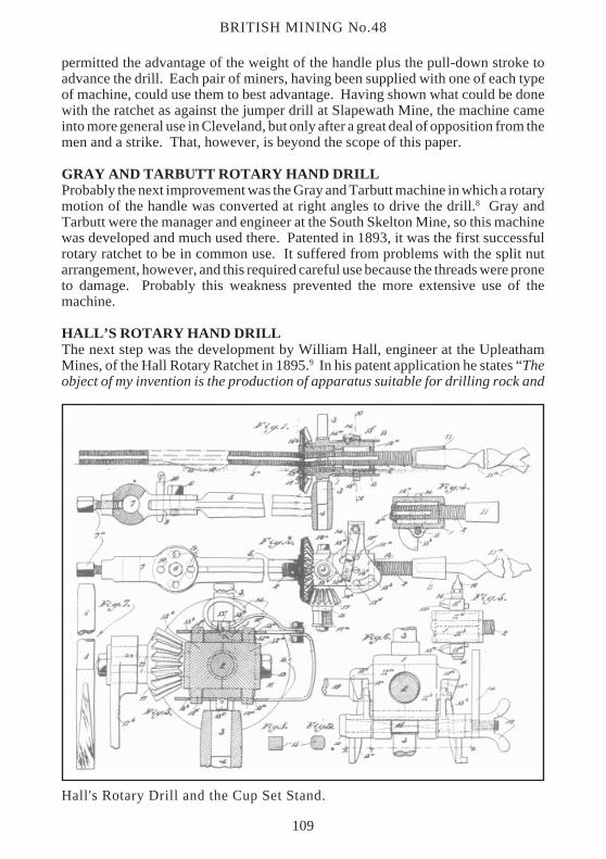
HALL’S ROTARY HAND DRILLThe next step was the development by William Hall, engineer at the UpleathamMines, of the Hall Rotary Ratchet in 1895.9 In his patent application he states “Theobject of my invention is the production of apparatus suitable for drilling rock and
Hall's Rotary Drill and the Cup Set Stand.
109
which shall be simple in construction, light, portable and easy to manipulate”. Thisseems to sum up the ideal for any drilling machine and applies today as readily asin 1895. Used at first in the Upleatham Mines, this drill was to be for a short periodmore widely used in the Cleveland Mines. The most important feature was thedevelopment of a new stand. Because the drill spindle was not encased in a metaltube, the usual ‘back set’ position could not be used and so a new stand, known asa ‘cup set’ carried the machine during drilling operations. A chisel-pointed iron barabout 20 inches long and 11/2 inches in diameter was driven into the ironstone. Alongthe bar slid a clam which could be held firm at any point by tightening a nut. Thelast part of the stand was a radial arm, with one end fitting into the clam and the otherend having a small cup into which a projection on the drill fitted. The radial arm wasfixed into place by inserting a pin through one of the holes in the clam and also inthe radial arm. The ratchet was then placed on the stand and drilling began. It provedunnecessary for the bar of the stand to be placed directly under the hole to be drilled.Instead, it could be placed to one side or even at right angles. William Hall claimedthat it was possible to move the stand to such an extent that two holes could be drilledfrom the one location.
There appears to have been very little trouble with the stand working loose duringdrilling operations and it seems that, in practice, the stand was pushed downwardsby the drill and this held the bar in place.
BLACKETT HUTTON ROTARY DRILLBy this time the shortcomings of the ratchets were well known. The fact that the splitnut had a problem of thread stripping, which required constant attention, led tofurther developments. Most of these locally designed machines were produced bythe firm of Messrs Southern & Co. at its Guisborough Foundry. During 1894, JohnBlackett, foreman fitter at the foundry, patented a simple form of ratchet drill.10
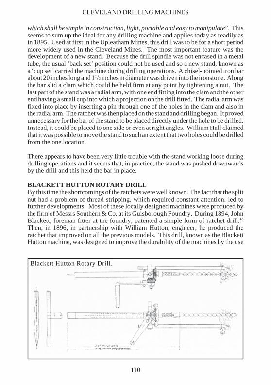
Then, in 1896, in partnership with William Hutton, engineer, he produced theratchet that improved on all the previous models. This drill, known as the BlackettHutton machine, was designed to improve the durability of the machines by the use
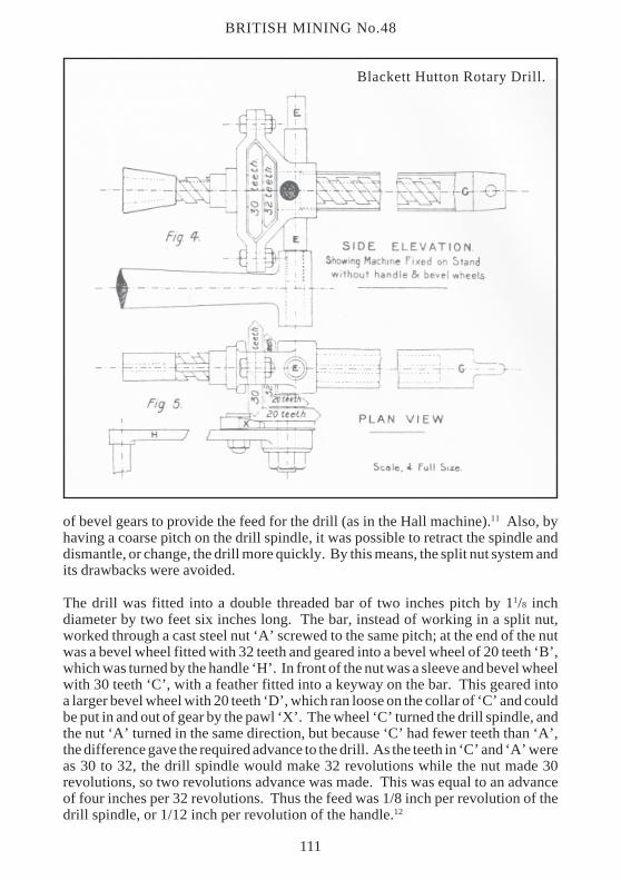
Blackett Hutton Rotary Drill.
CLEVELAND DRILLING MACHINES
110
BRITISH MINING No.48
of bevel gears to provide the feed for the drill (as in the Hall machine).11 Also, byhaving a coarse pitch on the drill spindle, it was possible to retract the spindle anddismantle, or change, the drill more quickly. By this means, the split nut system andits drawbacks were avoided.
The drill was fitted into a double threaded bar of two inches pitch by 11/8 inchdiameter by two feet six inches long. The bar, instead of working in a split nut,worked through a cast steel nut ‘A’ screwed to the same pitch; at the end of the nutwas a bevel wheel fitted with 32 teeth and geared into a bevel wheel of 20 teeth ‘B’,which was turned by the handle ‘H’. In front of the nut was a sleeve and bevel wheelwith 30 teeth ‘C’, with a feather fitted into a keyway on the bar. This geared intoa larger bevel wheel with 20 teeth ‘D’, which ran loose on the collar of ‘C’ and couldbe put in and out of gear by the pawl ‘X’. The wheel ‘C’ turned the drill spindle, andthe nut ‘A’ turned in the same direction, but because ‘C’ had fewer teeth than ‘A’,the difference gave the required advance to the drill. As the teeth in ‘C’ and ‘A’ wereas 30 to 32, the drill spindle would make 32 revolutions while the nut made 30revolutions, so two revolutions advance was made. This was equal to an advanceof four inches per 32 revolutions. Thus the feed was 1/8 inch per revolution of thedrill spindle, or 1/12 inch per revolution of the handle.12
Blackett Hutton Rotary Drill.
111
The two studs ‘EE’ were fitted one on each side of the machine, so that it could befixed either way up on the stand with the handle on the most convenient side fordrilling. This avoided the ‘handed’ machines mentioned earlier. The drill spindlewas protected by a steel pipe ‘G’, 11/2 inches in diameter and closed and pointed atone end. Besides protecting the drill spindle, the pipe was used to provide a holdagainst the side of the place when possible. When the Blackett Hutton was set upand ready to drill, the pawl ‘X’ was in gear and both the bar and the nut turned in thesame direction. Once the hole was complete, or to change the drill, the pawl wasdisengaged and the handle turned in the same direction. This turned the nut aloneand the drill spindle was brought back at the full pitch of two inches per revolution.Also, when setting up the machine to drill with the pawl out of gear, the drill couldbe tightened up to its work by turning the handle in the opposite direction.
The Blackett Hutton became the standard drill of the Cleveland mines and survivedinto the 1950s in some mines, having gradually replaced all the other hand-operateddrills. It proved to be popular, versatile and above all robust.
TWIST DRILLSThese varied in length from 1 foot 6 inches to 4 feet 6 inches according to thediscretion of the miner. Three drills was the normal complement of a working place.
Length Diameter WeightShort drill 1' 8" 13/4" 2 lbsYard drill 3' 0" 15/8" 31/2 lbsLong drill 4' 6" 19/16" 5 lbs
These drills were made of hard steel of fish-bellied section 13/8 inches thick and wereusually hand twisted by the mine blacksmith. The short and yard drills weresharpened to produce a larger hole than the long drill so that they could be extractedby hand. A drill key was provided among the tools of a place for this job.
DRILLS
WORK DONE BY RATCHETSWhen these machines were first introduced into the Cleveland mines, the systemwas for three men to work two places. One would be an experienced miner, with themachine, and he would drill and fire the required shots in both places. The other twowere employed to fill the blown-down stone into the tubs. In an 8 feet 6 inches thickseam of clean stone three men with one machine would get from 23 to 26 tons perday in the ‘whole’ workings with 12 to 14 holes.
This arrangement did not work very well and was replaced with a system of twominers in one place with one machine. The earlier system gave a larger output permachine but the latter system gave a larger output per working place. This provedto be an important item when working out the pillars because a lot of difficulty wasexperienced in making places ready to be used.
CLEVELAND DRILLING MACHINES
112
BRITISH MINING No.48
When two miners worked together, one man drilled while the other filled.Experienced miners took turns drilling and firing, or filling the tubs. Should theplace be working well, an output of 10 to 16 tons per day was possible. If they wereworking a place removing pillars then an output of much nearer 10 tons per daywas likely. When the pillars were being worked, stoppages were caused by thedeputies setting timber. More stone required barring down and more care wasneeded to prevent timbers being dislodged.
The average number of holes drilled in the ‘whole’ working was seven to nine pershift averaging 3 feet 6 inches per hole. In the pillar working or ‘brokens’ theaverage was 5 to 10 holes drilled and they tended to be of shorter length.
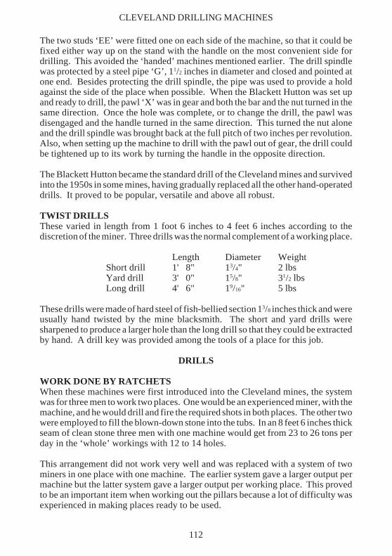
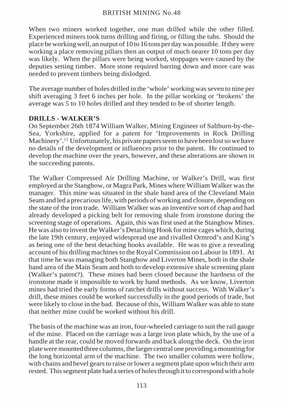
DRILLS - WALKER’SOn September 26th 1874 William Walker, Mining Engineer of Saltburn-by-the-Sea, Yorkshire, applied for a patent for ‘Improvements in Rock DrillingMachinery’.13 Unfortunately, his private papers seem to have been lost so we haveno details of the development or influences prior to the patent. He continued todevelop the machine over the years, however, and these alterations are shown inthe succeeding patents.
The Walker Compressed Air Drilling Machine, or Walker’s Drill, was firstemployed at the Stanghow, or Magra Park, Mines where William Walker was themanager. This mine was situated in the shale band area of the Cleveland MainSeam and led a precarious life, with periods of working and closure, depending onthe state of the iron trade. William Walker was an inventive sort of chap and hadalready developed a picking belt for removing shale from ironstone during thescreening stage of operations. Again, this was first used at the Stanghow Mines.He was also to invent the Walker’s Detaching Hook for mine cages which, duringthe late 19th century, enjoyed widespread use and rivalled Ormrod’s and King’sas being one of the best detaching hooks available. He was to give a revealingaccount of his drilling machines to the Royal Commission on Labour in 1891. Atthat time he was managing both Stanghow and Liverton Mines, both in the shaleband area of the Main Seam and both to develop extensive shale screening plant(Walker’s patent?). These mines had been closed because the hardness of theironstone made it impossible to work by hand methods. As we know, Livertonmines had tried the early forms of ratchet drills without success. With Walker’sdrill, these mines could be worked successfully in the good periods of trade, butwere likely to close in the bad. Because of this, William Walker was able to statethat neither mine could be worked without his drill.
The basis of the machine was an iron, four-wheeled carriage to suit the rail gaugeof the mine. Placed on the carriage was a large iron plate which, by the use of ahandle at the rear, could be moved forwards and back along the deck. On the ironplate were mounted three columns, the larger central one providing a mounting forthe long horizontal arm of the machine. The two smaller columns were hollow,with chains and bevel gears to raise or lower a segment plate upon which their armrested. This segment plate had a series of holes through it to correspond with a hole
113
Wal
ker’
s C
ompr
esse
d A
ir D
rill
, 18
74 m
odel
.
CLEVELAND DRILLING MACHINES
114
BRITISH MINING No.48
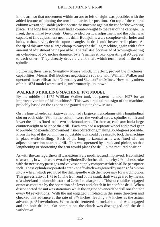
in the arm so that movement within an arc to left or right was possible, with theadded feature of pinning the arm in a particular position. On top of the centralcolumn was an adjustable jack to secure the machine against the roof of the workingplace. The long horizontal arm had a counterweight to the rear of the carriage. Infront, the arm had two joints. One provided vertical adjustment and the other wascapable of fine adjustment near the drill. Both joints were complete with holes andbolts, so that, having decided upon an angle, the drill could be secured in place. Atthe tip of this arm was a large clamp to carry the drilling machine, again with a fairamount of adjustment being possible. The drill itself consisted of two single-actingair cylinders, of 51/2 inches diameter by 21/2 inches stroke, operating at 90 degreesto each other. They directly drove a crank shaft which terminated in the drillspindle.
Following their use at Stanghow Mines which, in effect, proved the machines’capabilities, Messrs Bell Brothers negotiated a royalty with William Walker andoperated these drills at their Normanby and Skelton Park Mines. How many othersof this 1874 model were used is, unfortunately, unknown.
WALKER’S DRILLING MACHINE: 1875 MODELBy the middle of 1875 William Walker took out patent number 1657 for animproved version of his machine.14 This was a radical redesign of the machine,probably based on the experience gained at Stanghow Mines.
On the four-wheeled carriage was mounted a large central column with a longitudinalslot on each side. Within the column were the vertical screw spindles to lift andlower the plates fitted to the two horizontal arms. To the rear, each arm had a largecounterweight to balance the drill. Each arm had a separate wheel and bevel gearto provide independent movement in most directions, making 360 degrees possible.From the top of the column, an adjustable jack could be raised to lock the machinein place while drilling. Each of the long horizontal arms was fitted with anadjustable section near the drill. This was operated by a rack and pinion, so thatlengthening or shortening the arm would place the drill in the required position.
As with the carriage, the drill was extensively modified and improved. It consistedof a casting in which were two air cylinders 51/2 inches diameter by 21/2 inches strokewith the necessary passages and valves to supply compressed air at 40 lbs per squareinch. These cylinders operated a crank shaft which was geared by means of a pinioninto a wheel which provided the drill spindle with the necessary forward motion.This gave a ratio of 1.75 to 1. The front end of the crank shaft was geared by meansof a wheel and pinion with a ratio of 2.4 to 1 to a large nut. This nut could be engagedor not as required by the operation of a lever and clutch in front of the drill. Whendisconnected the nut was stationary while the engine advanced the drill one foot forevery 84 revolutions. With the nut engaged, it rotated in the same direction andchecked this advance at the rate of 83/4 inches, leaving 31/4 inches as the actualadvance per 84 revolutions. When the drill entered the rock, the clutch was engagedand the hole drilled. On completion, the clutch was disengaged and the drillwithdrawn.
115
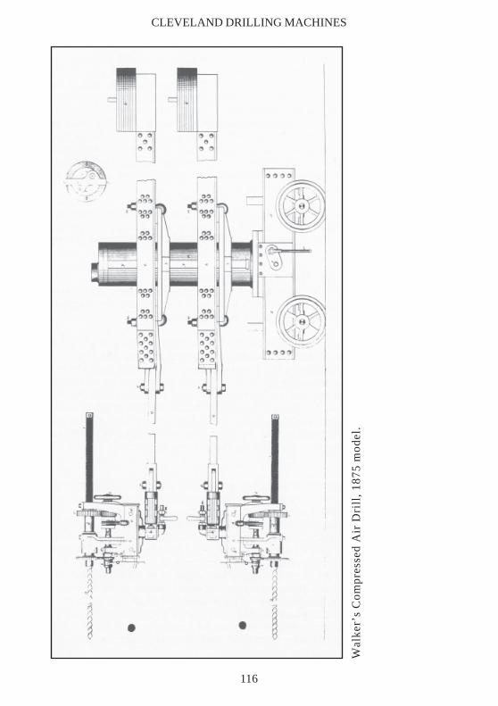
Wal
ker’
s C
ompr
esse
d A
ir D
rill
, 18
75 m
odel
.
CLEVELAND DRILLING MACHINES
116
BRITISH MINING No.48
The 1875 model drill was first introduced at the Boosbeck Mines by WilliamWalker, who was at the time mines manager for Messrs Stevenson, Jacques & Co.He was able to obtain 80 tons per shift per machine. Having seen the machine inaction, Messrs Bell Brothers Ltd placed an order for an example for Skelton Parkand Port Mulgrave Mines and eventually operated four machines.
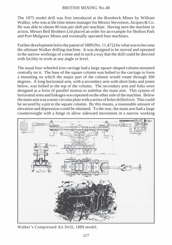
Further development led to the patent of 1889 (No. 11,472) for what was to becomethe ultimate Walker drilling machine. It was designed to be moved and operatedin the narrow workings of a mine and in such a way that the drill could be directedwith facility to work at any angle or level.
The usual four-wheeled iron carriage had a large square-shaped column mountedcentrally on it. The base of the square column was bolted to the carriage to forma mounting on which the major part of the column would rotate through 360degrees. A long horizontal arm, with a secondary arm with short links and jointsbelow, was bolted to the top of the column. The secondary arm and links weredesigned as a form of parallel motion to stabilise the main arm. This system ofhorizontal arms and linkages was repeated on the other side of the machine. Belowthe main arm was a semi-circular plate with a series of holes drilled in it. This couldbe secured by a pin to the square column. By this means, a reasonable amount ofelevation and depression could be obtained. To the rear, the main arm had a largecounterweight with a hinge to allow sideward movement in a narrow working
Walker’s Compressed Air Drill, 1889 model.
117
place. To the front, a similar hinge was fitted and this could be secured at variousangles by a bolt. Nearer the drill, a second smaller hinge allowed fine adjustmentsof angle to the drill unit alone. The compressed air drill fitted to this new carriagewas exactly the 1875 model. It proved to be the most successful of the Walker drills,with examples working into the 20th century. Over the years, a number of detailswere changed, eg. the central column developed angled faces, or the parallel motionhad straight links.
Walker drills in Cleveland Mines, 1892.
Stanghow 4Liverton 4North Skelton 6Skelton Park 4Lingdale 3Grinkle 4Lofthouse 7Upleatham 1
33
SYSTEM OF OPERATION.15
To operate the drill an experienced miner was selected. He was provided with ayouth to assist him and to train to the work. A horse pulled the machine from placeto place as the machine alone could weigh 21/2 tons! The place would be drilled asrequired, ready to be charged and fired, then the machine was moved to the nextlocation. About nine or ten places were the usual for a machine drilled district. Asecond experienced miner was chosen to train for the shot firer, following thedrilling team to charge and fire the holes. He had the hardest and most dangerouspart of the work, having to charge and fire 60 to 80 holes per shift. These twoexperienced miners were paid a fixed tonnage rate per ton which included the wagesof the youth. A further gang of 10 to 12 unskilled labourers followed the shotfirer,breaking up the fallen stone and loading it into tubs and sending them away to theshaft. This system of operation applied to all the power machines used in theCleveland mines. An unexpected advantage of the use of compressed air wasnoticed at the Liverton Mines, where a 30 feet diameter Guibal mine ventilating fanhad been erected and was usually working at 50 RPM, to provide efficientventilation. Following the introduction of Walker’s drills, even with the workingsa further 11/4 to 11/2 miles from the shafts than when the fan was put in, it was foundpossible to operate the Guibal fan at 20 RPM, and still have efficient ventilation.
DRILL - BURLEIGHBetween 1870 and 1873, Messrs Bolckow Vaughan & Co. sank to 720 feet thedeepest Cleveland mine at North Skelton (NZ675183). They found a Main Seamof ironstone of 91/2 feet thick, fortunately without the dreaded shale band. The greatdepth to the seam, however, meant that it was a compressed and, therefore, hardstone to work. To produce this ironstone at a profit, it was necessary to employ
CLEVELAND DRILLING MACHINES
118
BRITISH MINING No.48
power machines, rather than hand mining methods, from an early date. Variousmachines of the period were tried, but many failed because of the hardness of thestone. Negotiations were opened with William Walker, but the parties could notagree terms. At some date, probably about 1877, Bolckow Vaughan decided tooperate the compressed air percussive drills, which seem to have passed underseveral names, including McKean’s, Eclipse or Ingersol, but, as they were moreoften known as the Burleigh Drill, I will call them that.
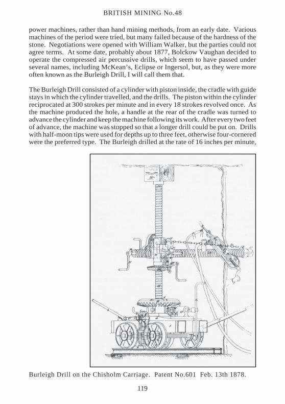
The Burleigh Drill consisted of a cylinder with piston inside, the cradle with guidestays in which the cylinder travelled, and the drills. The piston within the cylinderreciprocated at 300 strokes per minute and in every 18 strokes revolved once. Asthe machine produced the hole, a handle at the rear of the cradle was turned toadvance the cylinder and keep the machine following its work. After every two feetof advance, the machine was stopped so that a longer drill could be put on. Drillswith half-moon tips were used for depths up to three feet, otherwise four-corneredwere the preferred type. The Burleigh drilled at the rate of 16 inches per minute,
Burleigh Drill on the Chisholm Carriage. Patent No.601 Feb. 13th 1878.
119
which meant that a hole of 4 feet in depth took three minutes to complete. By 1880this machine was producing about 50 tons of ironstone per shift.16 At times 75 tonswere produced and, in exceptional places, 96 to 107 tons were possible in eighthours. One problem with the percussive system was that, unless water underpressure was put into the hole to flush the debris out, the paste formed soon jammedthe machine. This required the double expense of two systems of pipes to eachmachine. By this date seven Burleigh drills were operating at North Skelton Mine,each serving ten working places. Each machine required a skilled miner and a youthto work it, with a skilled shotfirer to charge and fire the holes. Four labourersfollowed the shotfirer to break up and load the ironstone into tubs.
Having heavy percussive drills was one thing, being able to operate and move themfrom place to place in a mine was another! By February 1878 James Chisholm,engineer to Messrs Bolckow Vaughan, developed and patented a four-wheeledcarriage from which to transport and operate the drill.17 Between the wheels a jackwas fitted on each side to keep the carriage in position while drilling. On thecarriage was a vertical narrow threaded column, capable of being raised to the roofof the place. Also threaded onto this vertical column was a block which could, bymeans of a worm gear and handle, be moved up and down. Through the block rana further threaded horizontal arm. Clamped to the end of, and at right angles to, thearm was the Burleigh drill. The horizontal arm could be further secured by beingpushed hard into the side of the place. A hose brought compressed air to the drill,a water hose was inserted into the hole and the air turned on.
Before long someone suggested a trial of the Burleigh against the Walker’s rotativedrill, but this took until 1882 to arrange. Over the period from November 1882 toJanuary 1883 both drills were working the Main Seam at North Skelton Mine. Theresult clearly showed the superiority of the Walker’s rotary drill. After these trialsno further Burleighs were purchased, but by 1893 the whole of the output was wonby Walker’s compressed air drills.
HYDRAULICFollowing the sinking of the Lumpsey Mine shafts by 1881, Messrs Bell Brothers Ltdbegan to look at the various methods of winning ironstone. The experience of capitaland running costs of the Walker drills was known from their use at the company’sSkelton Park Mines. Probably at this period Bell’s Mining Department had asextensive a knowledge of drills as any mining company in the north.
The company’s mining engineer, A.L. Stevenson, suggested utilising the pressure ofthe water held back by the tubbing in the shafts.18 He suggested that this would saveon the capital cost of compressing plant and, with a large area of ironstone to beworked to the rise of the shafts, the waste water could easily be run to the sump forpumping. At this stage the mine’s pumping engine was only working three or fourhours per day, so the extra work was not considered excessive.
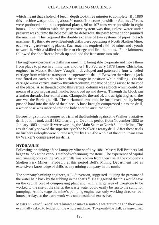
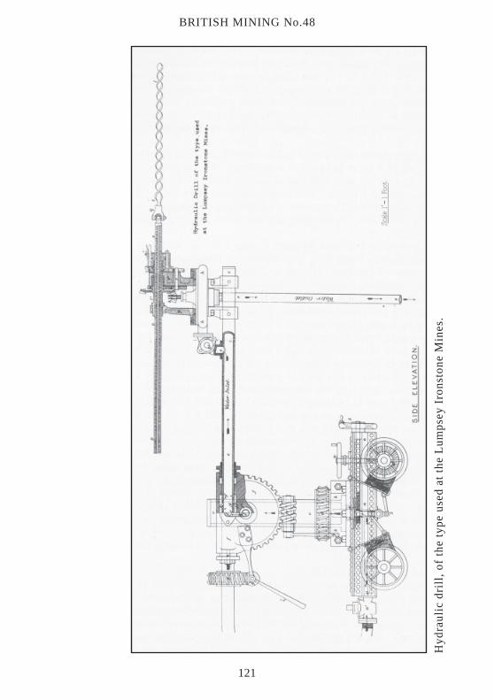
Messrs Gilkes of Kendal were known to make a suitable water turbine and they wereeventually asked to tender for the whole machine. To operate the drill, a range of six
CLEVELAND DRILLING MACHINES
120
BRITISH MINING No.48
Hyd
raul
ic d
rill
, of
the
typ
e us
ed a
t th
e L
umps
ey I
rons
tone
Min
es.
121
inch pipes was connected with the shaft tubbing at a depth of 50 fathoms in the upcastshaft and then taken to the workings. At the shaft bottom a pressure of 215 lbs PSIwas found to be available, showing that the full pressure of 500 feet of the mine shaftwas obtained. By the time the water in the pipes had travelled about one mile uphillat a slight gradient a pressure of 140 lbs PSI was available at the drill. The majordrawback of this system proved to be the long lengths of hose, especially when themachine was being moved from place to place.
The first machine started work on October 9th 1884 and over the first three monthsaveraged 55.4 holes per shift of eight hours. This produced 125.3 tons per shift and2.26 tons per hole, the cost of powder being 2.66d per ton of ironstone. To producethe 55.4 holes, 7,000 gallons of water were used. The pumping engine would haveneeded 20 minutes to remove this. During the three months ending October 9th1886, the machine was averaging over 152 tons per shift.
This hydraulic drill was patented during 1885 as No. 9985 by the inventors, MessrsThomas Hugh Bell, Iron Master, of Middlesbrough, Addison Langhorn Stevensonof Durham, Mining Engineer, and Robert Clough, of Page Bank Colliery Durham,Engineer. In the same patent, they describe a standard form of four-wheeledcarriage which was to form the basis of most of the experimental and productiondrills they developed. To allow movement, a handwheel geared to an axle was fitted.Rings were also fitted so that a horse could provide haulage. Brakes were fitted tooperate on one side of each axle only for use when drilling. On the deck of thecarriage was a central column, complete with a cross arm to which the drill with itswater turbine was clamped. The machine had to be capable of drilling holes in anypart of a working place, no matter how awkward! To provide that capability, thecentral column could be rotated on the carriage and the cross arm could be raised orlowered. The turbine and drill could be clamped at any point along the cross arm andthe drill could also be turned at right angles to the cross arm and locked into thatposition for drilling. The water was admitted to the rear of the carriage by a valve,then travelled up the central column, along the cross arm to the horizontally mountedturbine. A bevel gear wheel fixed on the turbine spindle meshed with a verticalbevelled gear wheel to provide the necessary rotary motion to the long drill spindle.To permit the quick retraction of the drill when the hole was complete, a handoperated version of the Stayner split nut was fitted. Accounts of these drills existfrom the early 1890s, then nothing more is written about them. They were developedfor a particular series of workings existing at one mine. Having done this work, themachines either went for scrap or the basic carriage may have been fitted with thelater electric drills.
DRILLS - PETROLEUMThe trio of Bell, Stevenson and Clough applied for a patent (No. 11,394) in 1890which covered a series of experimental drilling machines. One of these, for a petrol-engined machine, was developed and worked for some years with good results at theLumpsey Mines. In this case, the engine and drill were placed on a six wheeledcarriage whose rear wheels were of a smaller diameter. On the main shaft the enginewas a V-shaped belt sheave with motion transferred by means of a leather or gut belt.
CLEVELAND DRILLING MACHINES
122
BRITISH MINING No.48
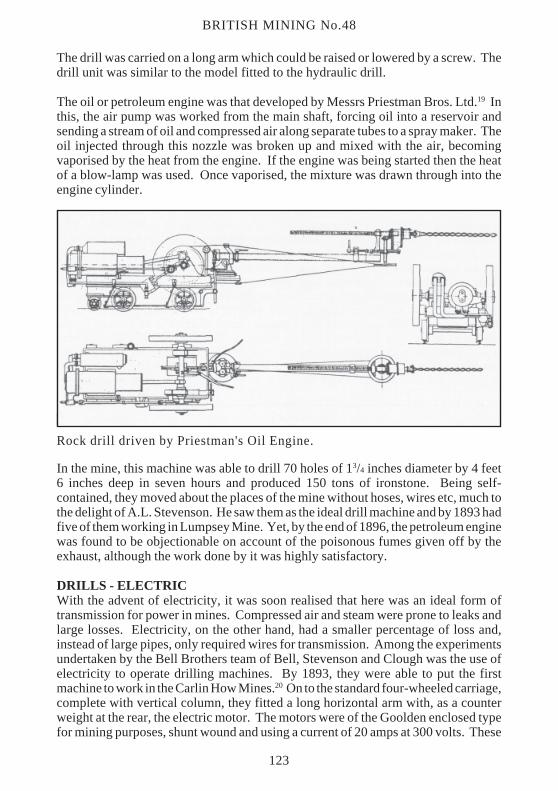
The drill was carried on a long arm which could be raised or lowered by a screw. Thedrill unit was similar to the model fitted to the hydraulic drill.
The oil or petroleum engine was that developed by Messrs Priestman Bros. Ltd.19 Inthis, the air pump was worked from the main shaft, forcing oil into a reservoir andsending a stream of oil and compressed air along separate tubes to a spray maker. Theoil injected through this nozzle was broken up and mixed with the air, becomingvaporised by the heat from the engine. If the engine was being started then the heatof a blow-lamp was used. Once vaporised, the mixture was drawn through into theengine cylinder.
In the mine, this machine was able to drill 70 holes of 13/4 inches diameter by 4 feet6 inches deep in seven hours and produced 150 tons of ironstone. Being self-contained, they moved about the places of the mine without hoses, wires etc, much tothe delight of A.L. Stevenson. He saw them as the ideal drill machine and by 1893 hadfive of them working in Lumpsey Mine. Yet, by the end of 1896, the petroleum enginewas found to be objectionable on account of the poisonous fumes given off by theexhaust, although the work done by it was highly satisfactory.
DRILLS - ELECTRICWith the advent of electricity, it was soon realised that here was an ideal form oftransmission for power in mines. Compressed air and steam were prone to leaks andlarge losses. Electricity, on the other hand, had a smaller percentage of loss and,instead of large pipes, only required wires for transmission. Among the experimentsundertaken by the Bell Brothers team of Bell, Stevenson and Clough was the use ofelectricity to operate drilling machines. By 1893, they were able to put the firstmachine to work in the Carlin How Mines.20 On to the standard four-wheeled carriage,complete with vertical column, they fitted a long horizontal arm with, as a counterweight at the rear, the electric motor. The motors were of the Goolden enclosed typefor mining purposes, shunt wound and using a current of 20 amps at 300 volts. These
Rock drill driven by Priestman's Oil Engine.
123
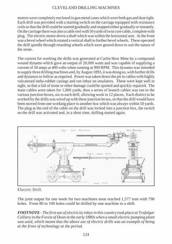
motors were completely enclosed in gun metal cases which were both gas and dust tight.Each drill was provided with a starting switch on the carriage equipped with resistancecoils so that the drill could be started gradually and stopped either gradually or instantly.On the carriage there was also a cable reel with 50 yards of twin core cable, complete withplug. The electric motor drove a shaft which was within the horizontal arm. At the frontwas a bevel wheel which rotated a vertical shaft to further bevel wheels. These operatedthe drill spindle through retarding wheels which were geared down to suit the nature ofthe stone.
The current for working the drills was generated at Carlin How Mine by a compoundwound dynamo which gave an output of 20,000 watts and was capable of supplying acurrent of 50 amps at 400 volts when running at 900 RPM. This dynamo was intendedto supply three drilling machines and, by August 1893, it was doing so, with further drillsand dynamos to follow as required. Power was taken down the pit in cables with highlyvulcanised india-rubber casings and run inbye on insulators. These were kept well insight, so that a fall of stone or other damage could be spotted and quickly repaired. Themain cables were taken for 1,000 yards, then a series of branch cables was run to thevarious junction boxes, six to each drill, allowing work in 12 places. Each district to beworked by the drills was wired up with these junction boxes, so that the drill would havebeen moved from one working place to another box which was always within 50 yards.The plug at the end of the cable on the drill was locked into a junction box, the switchon the drill was activated and, in a short time, drilling started again.
Electric Drill.
The joint output for one week for two machines soon reached 1,577 tons with 790holes. From 80 to 100 holes could be drilled by one machine in a shift.
FOOTNOTE - The first use of electricity inbye in this country took place at TrafalgarColliery in the Forest of Dean in the early 1880s when a small electric pumping plantwas used, which meant that the above use of electric drills was an example of beingat the front of technology at the period.
CLEVELAND DRILLING MACHINES
124
BRITISH MINING No.48
CONCLUSIONFrom the early days of Cleveland mining, the jumper drill was the only effective drill.The trials at Slapewath in 1886 brought the ratchet drill to a reasonable form and, by1900, this had almost replaced the old jumper method. The power machine developedfrom 1874 and, as long as the ‘whole’ workings were being created, reigned supreme.When working the broken became general, the awkwardness and size was very muchagainst power machines. Labour unrest in the early 1920s permanently closed severalof the machine-worked mines, e.g. Liverton and Stanghow, and this was the end of themachines. After 1900, the ratchet drill gradually replaced the power machines until theBlackett Hutton was almost the only drill used in Cleveland. This lasted until the 1940swhen American, carriage-mounted and, later, hand-held power machines were introduced.
General Results. £ Holes per hour Ironstone per shiftcost
Jumper drill - 1 5 to 8Ratchett drill 3 - about 18Compressed air drill 250 8 100 to 130Hydraulic drill 220 8 100 to 130Petroleum drill 375 8 100 to 130Electric drill 350 10 140
WALKER’S 1875 MODEL DRILLProduced 80 tons per eight hours, with 40 lbs PSI, two feet per minute = in 8 hours20 holes. Working two shifts 300 tons for three machines. Tons per hole averaged2.98 tons. Cost of powder 2.01d.
BURLEIGH16 inches per minute = 50 tons per shift. 75 to 90 tons sometimes.
WALKER’S 1875 MODELNorth Skelton, averaging daily 2 shifts, 325 tons.
WALKER DRILL800 to 1,050 tons per week of 45 hours average of 10.25 tons per man per shift. 80to 85 holes per eight hour shift.
HYDRAULIC DRILLAveraged 55.4 holes per eight hour shift producing 125.3 tons and 2.26 tons per hole.Powder cost 2.66d per ton. October 1886 averaged 152 tons per shift.
FOOTNOTE - During the days of the electric drills, two examples were sold to ironstone minesat Irthlingborough, Northamptonshire. At some time in the 1930s, a Cleveland mining engineerwent to manage these mines. He found the two drills abandoned somewhere about the mine and,remembering them from Cleveland, decided to put them back to work. They were refitted and hadnew electric motors put in and went on to serve these mines into the 1950s.
125
PETROLEUM DRILL70 holes in 71/5 hours = 150 tons or 900 tons per week. Powder 3.25d per ton. Costof oil 1d per HP per day.
ELECTRIC80 to 100 holes in an eight hour shift. One week two machines produced 1,577 tonswith 790 holes.
By 1904:- 47% of ironstone was ratchet mined.28% of ironstone was power machine mined.25% of ironstone was jumper mined.
WALKER’S DRILL 1880Each machine produces 56 tons per day. Say 300 working days, then output of 16,000to 17,000 tons per year. Each filler fills 11.25 tons per day.
DRILLS. AIR COMPRESSING PLANTPart of the capital cost of the compressed air system was spent on the large steamdriven compressing engines. Details of several of them are available.
NORTH SKELTON MINEThe air compressing engine was built by Messrs John Fowler & Co. of Leeds.21 It hada steam cylinder of 20 inches with a 22 inches air cylinder mounted in tandem. Bothcylinders had a stoke of 60 inches with steam supplied at 50 lbs PSI. This engine wassupplied to operate the Burleigh drills; when they were replaced by the Walker drillsit was capable of supplying air to them and continued in use for many years.
LOFTHOUSE MINESDuring 1891, Messrs Walker Brothers of Wigan supplied a single tandem compoundair compressor of High Pressure 28 inches and Low Pressure 48 inches, air cylinder40 inches, all with 72 inches of stroke.22 The house was built to take two of thesemachines but it was only in March 1896 that the other half of this compressing plantwas ordered. When complete, this was one of the largest compressors in the north ofEngland. It was supplying air at 60 lbs PSI to 17 drilling machines, three haulingengines and three pumps during 1904. At the time the nearest drilling machine was11/2 miles inbye with the furthest machine supplied being 31/2 miles away. This minewas the greatest user of the Walker drill with an average weekly output of 10,000 tons.
CLEVELAND DRILLING MACHINES
126
BRITISH MINING No.48
ACKNOWLEDGEMENTSI wish to thank the staff of the Science and Technology Department of the BirminghamReference Library for their helpful kindness in tracing obscure patents and referencesover several years.
REFERENCES
1. I’Anson, J.C. Notes on Ironstone Mining inCleveland, Engineering, 25/11/1892, pp.653f
2. Tomlinson, J.R. & Dack, J.C. Ironstone Miningin Cleveland, Association of Colliery Managers,20/11/1939, pp.171-199
3. Seymour, F. A Contrast in Cleveland, Iron andCoal Trades Review, 19/08/1904, pp.554-556
4. Charlton, W. Use of Ratchet and other HandMachine Drills in the Cleveland Mines,Transactions of the Federated Institution of MiningEngineers, Vol.XXIV (1902-3), pp.526-535
5. Mining Journal, Vol.40, 01/10/1870, p.822
6. Charlton Drills, 1902-3
7. Patent No.9008, 1886
8. Patent No.23,804, 1893 (Not taken out)
9. Patent No.7039, 1895
10. Patent No.19,084, 1893
11. Patent No.1706, 1896
12. Clive, R. Cleveland Mining and the handrotary drilling machine, British Society of MiningStudents, Vol.26 No.4 (1904), pp.81-89
13. Patent No.3299, 1874
14. Stevenson, A.L. On the machinery at theSkelton Park and Lumpsey Mines, North EastInstitution of Mining and Mechanical Engineers,Vol.31 (1882), pp.105-110
15. Royal Commission on Labour, Book 25.Minutes of Evidence, Question 1572, 1892
16. President’s Address, Cleveland Institution ofEngineers, 1880-81, 15/11/1880, pp.18-20
17. Patent No.601, 1878
18. Stevenson, A.L. On the System of WorkingIronstone at the Lumpsey Mines by hydraulic drills,North East Institution of Mining and MechanicalEngineers, Vol.36 (1886-7), pp.67-72
19. Visit to Lumpsey Mines, Cleveland Institutionof Engineers, 21/06/1890, pp.206-208
20. Stevenson, A.L. Description of the Electricrock drilling machinery at the Carlin How IronstoneMines in Cleveland, Institution of MechanicalEngineers, 1893, pp.309-317
21. Visit to North Skelton Ironstone Mines ,Institution of Mechanical Engineers, 1893, p.369
22. Seymour Contrast in Cleveland, 1904
Paper submitted - 1992: N.A. Chapman,14 Dorset Road,Edgbaston,BIRMINGHAMB17 8EN
127


![Neotropical Primates in a Regenerating Costa Rican Dry ...fedigan/IJP Fedigan and Jack 2001.pdf · International Journal of Primatology [ijop] PP104-298605 October 1, 2001 15:18 Style](https://img.pdfslide.us/doc/110x75/5edc72f4ad6a402d66671c4f/neotropical-primates-in-a-regenerating-costa-rican-dry-fediganijp-fedigan-and.jpg)