Embed Size (px)
Citation preview
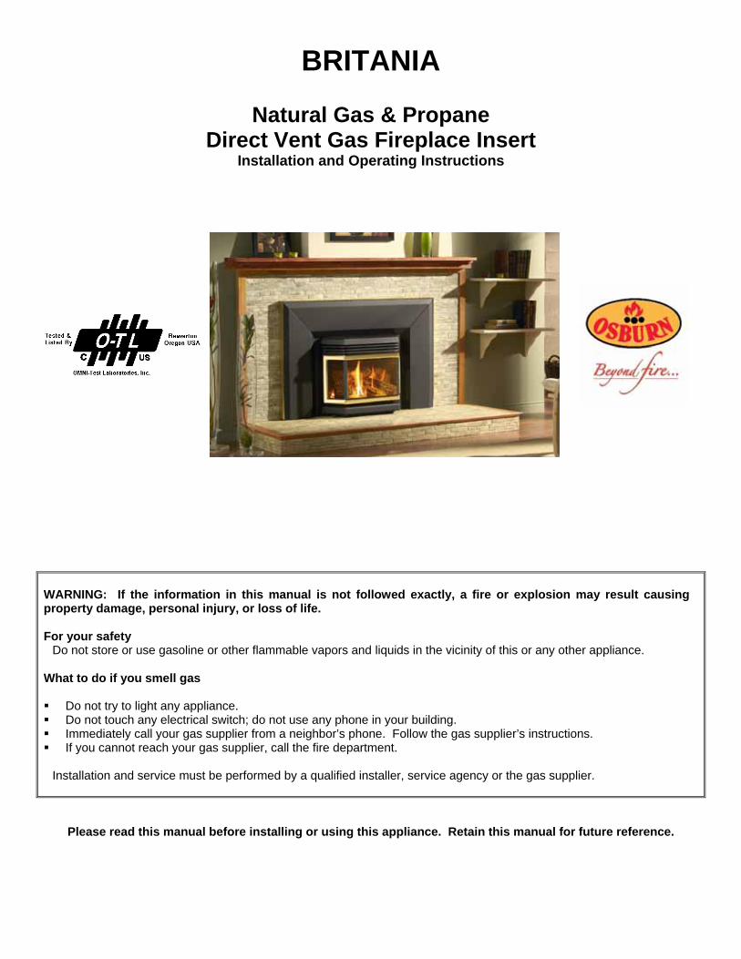
BRITANIA
Natural Gas & Propane Direct Vent Gas Fireplace Insert
Installation and Operating Instructions
WARNING: If the information in this manual is not followed exactly, a fire or explosion may result causing property damage, personal injury, or loss of life. For your safety
Do not store or use gasoline or other flammable vapors and liquids in the vicinity of this or any other appliance.
What to do if you smell gas Do not try to light any appliance. Do not touch any electrical switch; do not use any phone in your building. Immediately call your gas supplier from a neighbor’s phone. Follow the gas supplier’s instructions. If you cannot reach your gas supplier, call the fire department.
Installation and service must be performed by a qualified installer, service agency or the gas supplier.
Please read this manual before installing or using this appliance. Retain this manual for future reference.
1
Table of Contents 1.0 INTRODUCTION.............................................................................................................................. 2
1.1 SPECIFICATIONS ..................................................................................................................................... 2 1.2 FEATURES................................................................................................................................................. 4 1.3 INTENDED USE ......................................................................................................................................... 4 1.4 GENERAL SAFETY ................................................................................................................................... 4
2.0 OPERATION ........................................................................................................................................ 5
2.1 OPERATION SAFETY ............................................................................................................................... 5 2.2 LIGHTING INSTRUCTIONS ...................................................................................................................... 6 2.3 HEAT OUTPUT ADJUSTMENT ................................................................................................................ 7 2.4 FAN OPERATION ...................................................................................................................................... 7
3.0 INSTALLATION................................................................................................................................ 7
3.1 INSTALLATION AND SAFETY NOTES..................................................................................................... 7 3.2 UNPACKING .............................................................................................................................................. 7 3.3 INSTALLATION .......................................................................................................................................... 7 3.3.1 MINIMUM CLEARANCES TO COMBUSTIBLES .............................................................................................. 8 3.3.2 GAS LINE INSTALLATION .......................................................................................................................... 10 3.3.3 THERMOSTAT OR WALL SWITCH INSTALLATION ...................................................................................... 10 3.3.4 VENT INSTALLATION ................................................................................................................................ 13 3.3.5 FACEPLATE INSTALLATION ...................................................................................................................... 18 3.3.6 FIRE BOX COMPONENTS INSTALLATION .................................................................................................. 20 3.3.7 INITIAL FIRING .......................................................................................................................................... 24 3.3.8 BURNER REMOVAL .................................................................................................................................. 29 3.3.9 FIELD CONVERSIONS .............................................................................................................................. 30
4.0 MAINTENANCE ............................................................................................................................ 31
4.1 MAINTENANCE SAFETY ........................................................................................................................ 31 4.2 RECOMMENDED SERVICE ................................................................................................................... 31 4.3 GLASS CLEANING .................................................................................................................................. 31 4.4 CLEANING OF GOLD PLATED SURFACES ......................................................................................... 32 4.5 BURNER & PILOT CLEANING............................................................................................................... 32 4.6 FAN REPLACEMENT & ELECTRICAL SCHEMATIC............................................................................ 32
5.0 TROUBLE SHOOTING............................................................................................................. 34
6.0 REPLACEMENT PARTS......................................................................................................... 36
OSBURN LIMITED LIFETIME WARRANTY.................................................................. 37
2
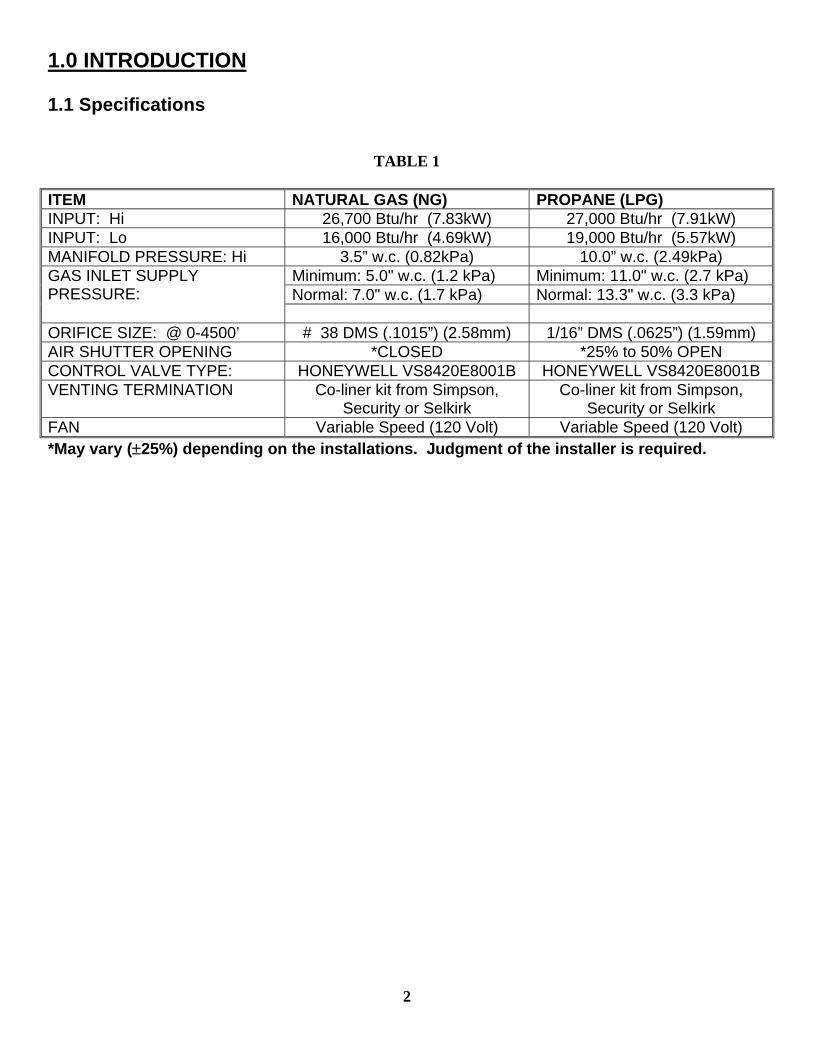
1.0 INTRODUCTION 1.1 Specifications
TABLE 1 ITEM NATURAL GAS (NG) PROPANE (LPG) INPUT: Hi 26,700 Btu/hr (7.83kW) 27,000 Btu/hr (7.91kW) INPUT: Lo 16,000 Btu/hr (4.69kW) 19,000 Btu/hr (5.57kW) MANIFOLD PRESSURE: Hi 3.5” w.c. (0.82kPa) 10.0” w.c. (2.49kPa)
Minimum: 5.0" w.c. (1.2 kPa) Minimum: 11.0" w.c. (2.7 kPa) Normal: 7.0" w.c. (1.7 kPa) Normal: 13.3" w.c. (3.3 kPa)
GAS INLET SUPPLY PRESSURE:
ORIFICE SIZE: @ 0-4500’ # 38 DMS (.1015”) (2.58mm) 1/16” DMS (.0625”) (1.59mm) AIR SHUTTER OPENING *CLOSED *25% to 50% OPEN CONTROL VALVE TYPE: HONEYWELL VS8420E8001B HONEYWELL VS8420E8001B VENTING TERMINATION Co-liner kit from Simpson,
Security or Selkirk Co-liner kit from Simpson,
Security or Selkirk FAN Variable Speed (120 Volt) Variable Speed (120 Volt) *May vary (±25%) depending on the installations. Judgment of the installer is required.
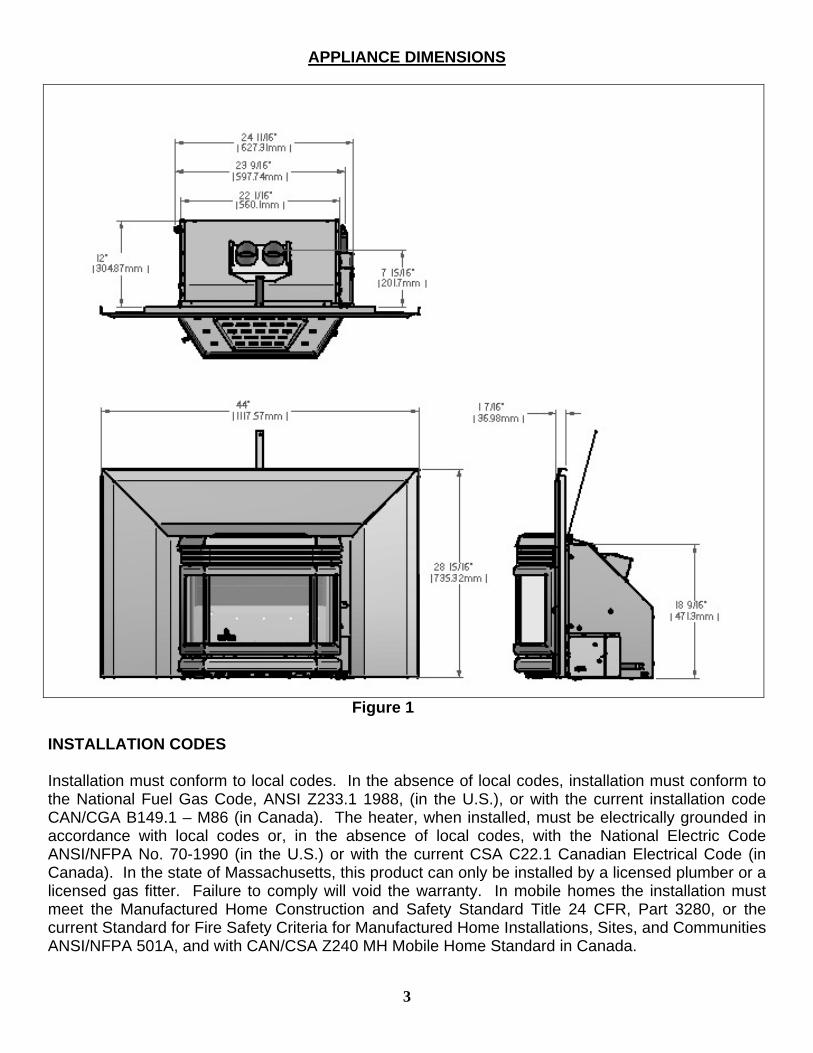
APPLIANCE DIMENSIONS
Figure 1
INSTALLATION CODES Installation must conform to local codes. In the absence of local codes, installation must conform to the National Fuel Gas Code, ANSI Z233.1 1988, (in the U.S.), or with the current installation code CAN/CGA B149.1 – M86 (in Canada). The heater, when installed, must be electrically grounded in accordance with local codes or, in the absence of local codes, with the National Electric Code ANSI/NFPA No. 70-1990 (in the U.S.) or with the current CSA C22.1 Canadian Electrical Code (in Canada). In the state of Massachusetts, this product can only be installed by a licensed plumber or a licensed gas fitter. Failure to comply will void the warranty. In mobile homes the installation must meet the Manufactured Home Construction and Safety Standard Title 24 CFR, Part 3280, or the current Standard for Fire Safety Criteria for Manufactured Home Installations, Sites, and Communities ANSI/NFPA 501A, and with CAN/CSA Z240 MH Mobile Home Standard in Canada.
3
4
1.2 Features Ignition system: Standing pilot ignition system with thermopile and thermocouple flame detection and piezo igniter. Gas control: Automatic millivolt powered combination gas control valve with variable flame control for convenience and on/off switch, optional wall thermostat, and/or optional wireless remote control are available. The gas valve does not require electricity from an external source. Fan control Variable speed control, the knob controls the fan speed in connection with a heat sensitive switch which turns on when the heater reaches operating temperature. Turning the knob counter-clockwise turns it to the “Off” position. Safety controls: A safety switch (thermocouple) will shut the system down in the event of loss of pilot flame, installation is not adequate or if flue is blocked. Outside combustion air supply: The combustion air supply is obtained entirely from outside the heated living space by the intake of outside air through the vent termination and down a 3" aluminum vent. 1.3 Intended use This appliance is intended to be used as a direct vent (top venting) fireplace insert heater and is suitable for installation into masonry fireplaces, or into certified factory built fireplaces which include a gas line knockout and proper floor clearances or in a Osburn zero clearance kit. A masonry fireplace must meet the minimum building code requirements or the equivalent, for a safe installation. Factory built fireplaces and their chimneys must be certified and meet local code requirements. Both must be free from cracks, blockage, creosote deposits, loose mortar, or other types of deterioration. . In Massachusetts the Britania may be installed in a bedroom only when used as a direct vent unit (sealed combustion). For other states or provinces it may be installed in a bedroom provided that CR89-00 and/or ANSI A225.1/NFPA 501A standards are followed, all required clearances are met, a wall thermostat is installed and where the maximum input is within 50 cubic feet of room volume per 1000 BTU/hr, (i.e.1500 minimum cubic feet) and hooked up to a Simpson GS Dura Vent , Security Chimneys International (Secure Vent) or Selkirk (Direct-Temp) co-liner vent termination(refer to page 14). 1.4 General safety The appliance must be properly connected to a venting system in accordance with local codes. This unit must not be connected to a chimney or flue serving any other appliance. It is equipped with a safety control system to protect against improper venting of flue products.
WARNING: Operation of this unit when not connected to a properly installed and maintained venting system may result in carbon monoxide poisoning.
Installation and repair should be done by a qualified service person. The appliance should be inspected before use and at least annually by a professional service technician. Provide adequate clearances around air openings, for combustion and ventilation air, and allow accessibility clearance for servicing and proper operation.
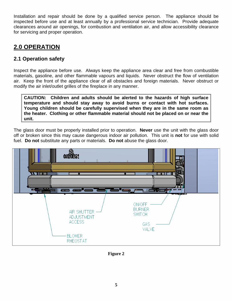
2.0 OPERATION 2.1 Operation safety Inspect the appliance before use. Always keep the appliance area clear and free from combustible materials, gasoline, and other flammable vapours and liquids. Never obstruct the flow of ventilation air. Keep the front of the appliance clear of all obstacles and foreign materials. Never obstruct or modify the air inlet/outlet grilles of the fireplace in any manner.
CAUTION: Children and adults should be alerted to the hazards of high surface temperature and should stay away to avoid burns or contact with hot surfaces. Young children should be carefully supervised when they are in the same room as the heater. Clothing or other flammable material should not be placed on or near the unit.
The glass door must be properly installed prior to operation. Never use the unit with the glass door off or broken since this may cause dangerous indoor air pollution. This unit is not for use with solid fuel. Do not substitute any parts or materials. Do not abuse the glass door.
Figure 2
5
2.2 Lighting instructions
FOR YOUR SAFETY, READ BEFORE LIGHTING
WARNING: If you do not follow these instructions exactly, a fire or explosion may result causing property damage, personal injury or loss of life.
A. This appliance has a pilot which must be lighted by hand. When lighting the pilot, follow these instructions exactly. B. BEFORE LIGHTING smell all around the appliance area for gas. Be sure to smell next to the floor because some gas is heavier than air and will
settle on the floor. WHAT TO DO IF YOU SMELL GAS
• Do not try to light any appliance. • Do not touch any electric switch; do not use any phone in your building. • Immediately call your gas supplier from a neighbours phone. Follow the gas supplier’s instructions. • If you cannot reach your gas supplier, call the fire department.
C. Use only your hand to push in or turn the gas control knob. Never use tools. If the knob will not push in or turn by hand, don’t try to repair it, call a qualified service technician. Force or attempted repair may result in a fire or explosion.
D. Do not use this appliance if any part has been under water. Immediately call a qualified service technician to inspect the appliance and to replace any part of the control system and any gas control which has been under water.
LIGHTING INSTRUCTIONS
6
1. STOP! Read the safety information above on this label. 2. Set the thermostat to the lowest setting. 3. Turn off all electric power to the appliance. 4. Controls are accessed by opening the access panel located on the right side faceplate. 5. Push in gas control knob slightly and turn clockwise to “OFF”. 6. Wait five (5) minutes to clear out any gas. Then smell for gas, including near the floor. If you smell gas, STOP! Follow “B” in the safety
information above on this label. If you don’t smell gas, go to the next step. 7. Turn control knob counterclockwise pilot position. 8. Depress control knob and push in piezo igniter button. Once pilot ignites continue to hold the control knob in for one (1) minute after the pilot is lit.
Release knob and it will pop back up. Pilot should remain lit. If it goes out, repeat steps 4 – 7. • If knob does not pop up when released, stop and immediately call your service technician or gas supplier. • If the pilot will not stay lit after several attempts, turn the gas control knob to “OFF” and call your service technician or gas supplier.
9. Turn gas control knob counterclockwise to “ON”. Turn on all electric power to the appliance. Set thermostat to desired setting or turn appliance switch to “ON” position then close bottom louver.
TO TURN GAS OFF TO APPLIANCE 1.Set thermostat to lowest setting. 2.Turn off all electric power to the appliance if service is to be performed. 3.Push in gas control knob slightly and turn clockwise to “OFF”, do not force. Note: The valve is equipped with a safety lockout, once in the “OFF” position you must wait until the thermopile has cooled before attempting to light the pilot (approximately 3 minutes).
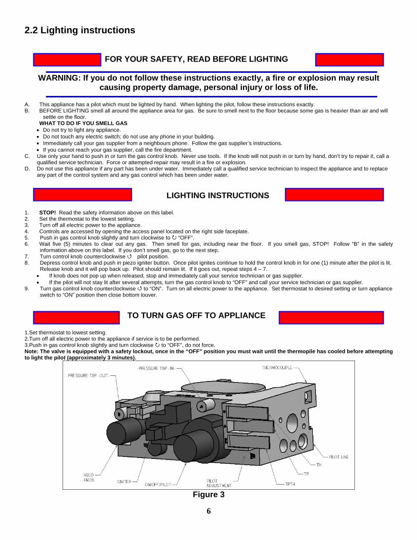
Figure 3
7
2.3 Heat output adjustment The valve supplied with the appliance has a HI/LO knob to control the heat output and flame height (Figures 3). 2.4 Fan operation The fan control knob is located under the left side of the decorative ash tray(figure 2), and may be adjusted to the following settings: OFF: Turn the control fully counter-clockwise until the switch operates. Variable Speed Setting: Turn the control to the desired setting. When the knob is turned fully clockwise the fan will set to minimum speed.
Do not use this appliance if any part has been under water. Immediately call a qualified service technician to inspect the appliance and to replace any part of the control system and any gas controls which have been under water. 3.0 INSTALLATION 3.1 Installation and safety notes Read all instructions before starting installation and follow them carefully during installation to ensure maximum benefit and safety. Failure to follow these instructions will void your warranty and may present a fire hazard. See the warranty at the back of this manual for disclaimers regarding improper installation. This fireplace insert and its components are tested and safe when installed in accordance with this installation manual. ELECTRICAL GROUNDING NOTE: A three-prong (grounding) plug, for your protection against shock hazard, is provided and should be plugged directly into a properly grounded three-prong receptacle. Do not cut or remove the grounding prong from this plug.
WARNING: Do not connect 120 VAC to the gas control valve or it’s wiring, as this will damage the valve.
3.2 Unpacking Please check the appliance carefully for any damaged or missing components (specifically check the glass condition). Report any problems to your dealer. This unit is shipped with the logs in a separate package. 3.3 Installation For satisfactory results it is necessary to plan certain aspects of the installation prior to the appliance’s final positioning. These include the vent system, the gas piping, and the fan wiring. Combustible surfaces such as the hearth, mantle, and facing must also be planned for.
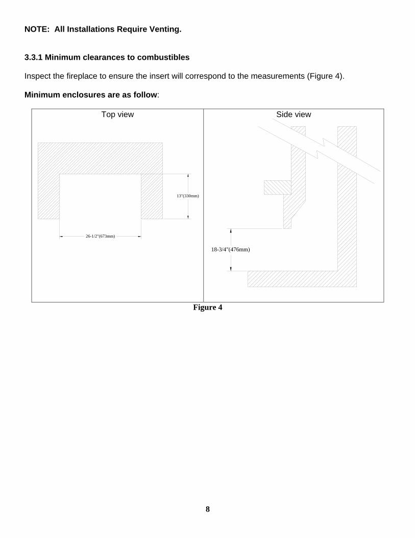
NOTE: All Installations Require Venting. 3.3.1 Minimum clearances to combustibles Inspect the fireplace to ensure the insert will correspond to the measurements (Figure 4). Minimum enclosures are as follow:
Top view
13"(330mm)
26-1/2"(673mm)
Side view
18-3/4"(476mm)
Figure 4
8

Minimum Clearances to Combustibles:
Combustiblesurface
Non-combustible surface
No floor protection needed, if unit is sitting at least 5 inches above the floor
Figure 5 Figure 6
10"(255mm)
4"(102mm)
6"(153mm)
8"(204mm)
8.50"(217mm)
9.75"(249mm)
11.25"(287mm)
14.00"(357mm)
12.50"(319mm) 2"
(51mm)
COMBUSTIBLE SIDE MANTLE
FLOOR PROTECTION
E G
A
D
F
C
COMBUSTIBLE SHELF
COMBUSTIBLE TOP MANTLE
COMBUSTIBLE SIDE WALL
HB
Figure 7a Figure 7b A- Combustible side wall to unit B- Combustible side mantle to unit C- Combustible top mantle to unit D- Combustible shelf to unit E- Minimum floor protection in front of unit F,G,H- Minimum enclosure dimension
12 1/2” 12 1/2”
21” 21” (figure 7a)
0” (figure 6) or 16” (figure 5) (figure 4)
Note: When using paint or lacquer to finish the mantle, such paint or lacquer must be heat resistant to prevent discoloration.
9
10
3.3.2 Gas line installation Install supply line using any piping approved for your installation meeting CAN/CGA 6.10, AA 3,
ANSI Z21.24 or Z21.45. A qualified gas fitter should install the gas line in accordance with all local building codes. If codes permit, coiled copper tubing may be used for gas supply.
Pressure taps are provided on the gas control for test gauge connections to measure the manifold and inlet pressures.
This appliance must be isolated from the gas supply piping system by closing its individual manual shut off valve during any pressure testing of the gas supply piping system at test pressures equal to or less than 1/2 psig (3.45 kPa).
The appliance and its individual shut off valve must be disconnected from the gas supply piping system during any pressure testing of the system at test pressures in excess of 1/2 psig (3.45 kPa).
Install the gas line as follows: The gas line connection found on the back of the valve is a 3/8" black iron nipple. An AGA and/or
CGA approved shut off valve can be installed in conjunction with the nipple if so desired. Installing the shut off valve on the end of the nipple will allow quick accessibility.
Upon initial firing check manifold pressure at pressure tap located on the front of the control valve (Figure 3).
WARNING: Do not use an open flame to test for gas leaks.
3.3.3 Thermostat or wall switch installation The burner control switch is located on under the bottom right hand side of the decorative ash lip (Figure 2). For your convenience, the unit can also be operated by a thermostat, or a wall switch control. Millivolt thermostats are available from any authorized Osburn dealer. Bedroom installations require the use of a wall thermostat.
NOTE: The thermostat or wall switch MUST be rated for millivolt use. Minimize splicing in all millivolt wiring & solder all unavoidable splices.
3.3.3.1 Remote control installation Please refer to instructions included with the optional accessory kit. 3.3.3.2 Thermostat or wall switch installation 1. Mount the thermostat or wall switch in the desired location and run "two conductor thermostat
wire" to the burner control switch (Figure 8a). To bypass the burner control switch, run the wires directly to the gas valve (Figure 8b).
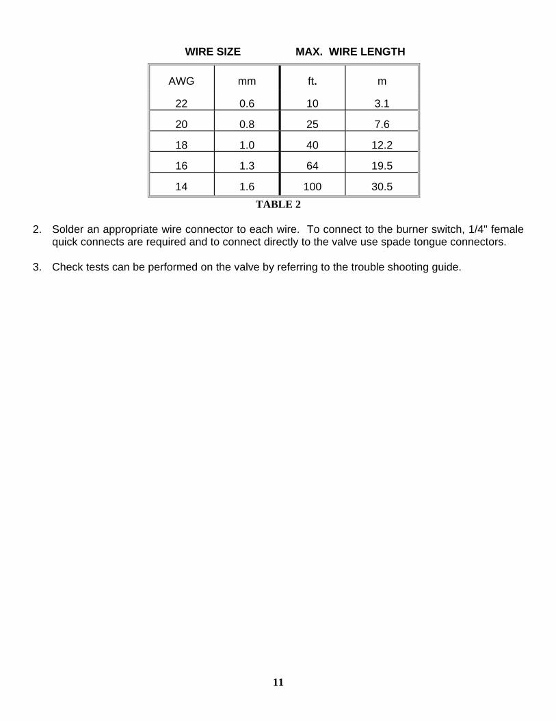
Purchase "two conductor thermostat wire", which is not provided, at any local supplier. The gauge of thermostat wire will determine the maximum wire length and distance at which to locate the thermostat or wall switch. See table 2 below and the information packaged with the thermostat. Be aware that, as the length of wire increases, the probability of adequate operating voltage decreases.
THERMOSTAT WIRE INFORMATION
11
WIRE SIZE MAX. WIRE LENGTH
AWG
mm
ft.
m
22
0.6
10
3.1
20
0.8
25
7.6
18
1.0
40
12.2
16
1.3
64
19.5
14
1.6
100
30.5 TABLE 2
2. Solder an appropriate wire connector to each wire. To connect to the burner switch, 1/4" female
quick connects are required and to connect directly to the valve use spade tongue connectors. 3. Check tests can be performed on the valve by referring to the trouble shooting guide.
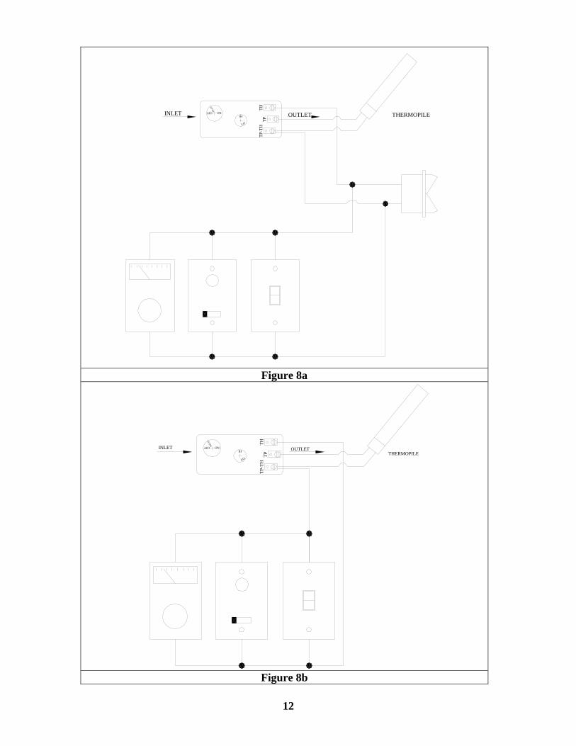
INLET PILO
T
THOFF ON
LO
HI
TP-T
HTP
OUTLET THERMOPILE
Figure 8a
INLET OFF ON
PILO
T
TP-T
HLO
HI
TPTH
OUTLETTHERMOPILE
Figure 8b
12
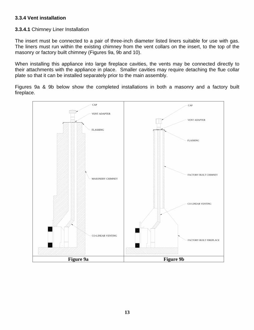
3.3.4 Vent installation 3.3.4.1 Chimney Liner Installation The insert must be connected to a pair of three-inch diameter listed liners suitable for use with gas. The liners must run within the existing chimney from the vent collars on the insert, to the top of the masonry or factory built chimney (Figures 9a, 9b and 10). When installing this appliance into large fireplace cavities, the vents may be connected directly to their attachments with the appliance in place. Smaller cavities may require detaching the flue collar plate so that it can be installed separately prior to the main assembly. Figures 9a & 9b below show the completed installations in both a masonry and a factory built fireplace.
CO-LINEAR VENTING
MASONERY CHIMNEY
FLASHING
VENT ADAPTER
CAP
FACTORY BUILT FIREPLACE
CO-LINEAR VENTING
FACTORY BUILT CHIMNEY
FLASHING
VENT ADAPTER
CAP
Figure 9a Figure 9b
13
14
Installation steps are as follows: 1. Position the insert in the fireplace cavity and note the required positions of the vent and gas
line. 2. To prevent damage to the insert, remove it until after the gas and vent lines have been
positioned. 3 a. Measure and cut two liner lengths just slightly longer than required.
Reminder: Minimum overall vent height is 10' and maximum is 30'. Joining two lengths of liner can be accomplished using 3" DF Flex Couplings. Join the lengths by liberally applying High Temperature Sealant to the end of the liner before inserting it onto the coupling, and once inserted, secure each connection with three screws.
From the top of the chimney:
b. Install the flashing onto the existing chimney.
c. Attach the liners to the two 3" outlets on the approved Chimney Liner Termination Kit by
first liberally applying High Temperature Sealant to the gasketed joint, and then pushing the liner onto the collar. Secure each joint using three screws.
d. CLEARLY IDENTIFY the lower end of the liners for intake and exhaust.
e. Feed the liners down the chimney through the flashing.
f. Install the cap onto the Round Adapter.
From below: 4. Liberally apply High Temperature Sealant to the outsides of the vent collars. 5. For installations that do not require the removal of the vent connector plate:
a. Push the insert back into the enclosure b. Slide the liner onto the appropriate vent collars and secure them with three screws each
and/or hose clamps. Note: Make sure the previously identified exhaust liner is connected to the exhaust collar (see Figures 10 & 11).
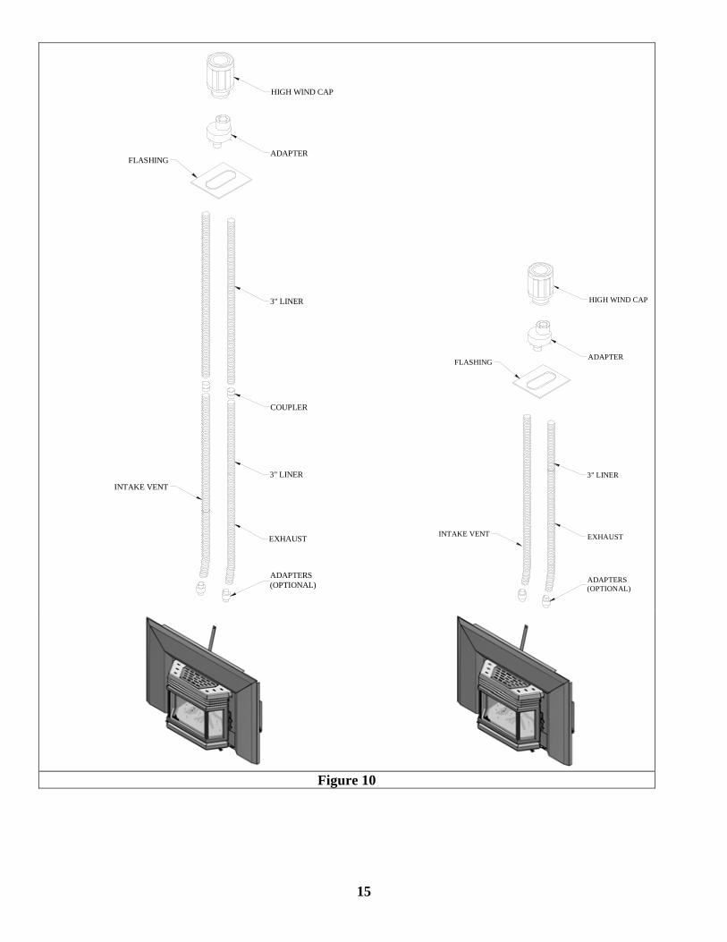
3" LINER
COUPLER
ADAPTERS(OPTIONAL)
INTAKE VENT
EXHAUST
3" LINER
FLASHING
HIGH WIND CAP
ADAPTER
ADAPTERS(OPTIONAL)
EXHAUSTINTAKE VENT
3" LINER
FLASHINGADAPTER
HIGH WIND CAP
Figure 10
15
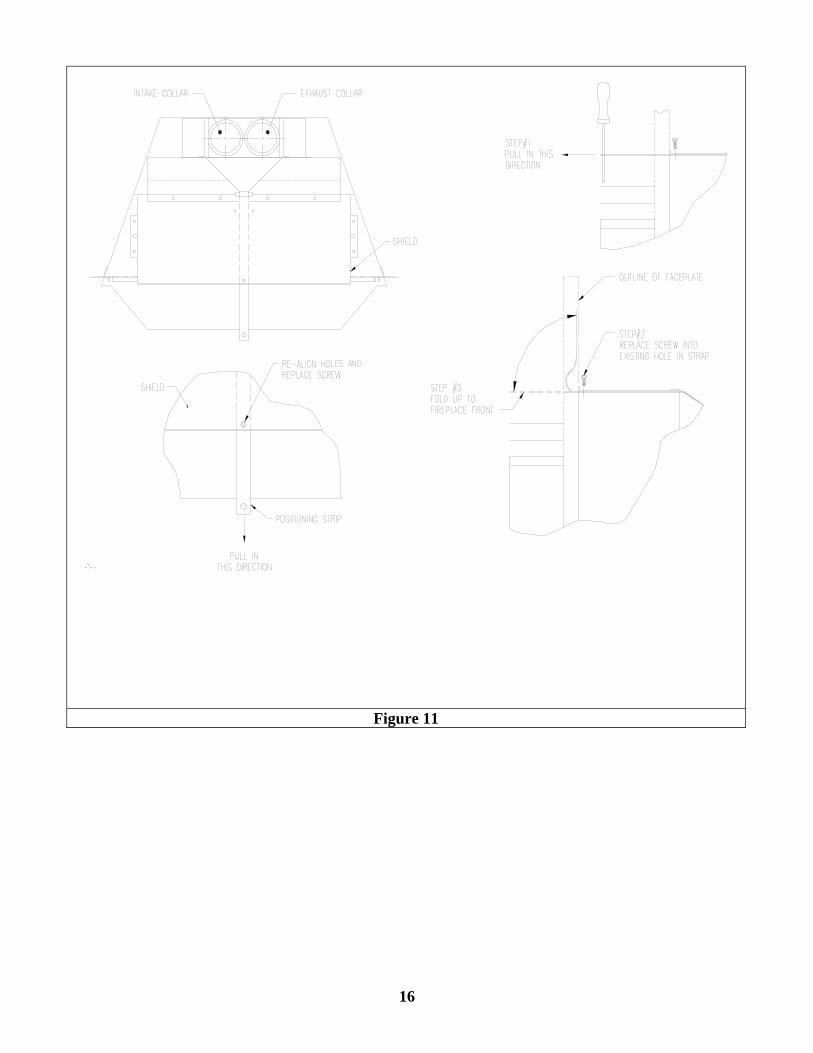
Figure 11
16
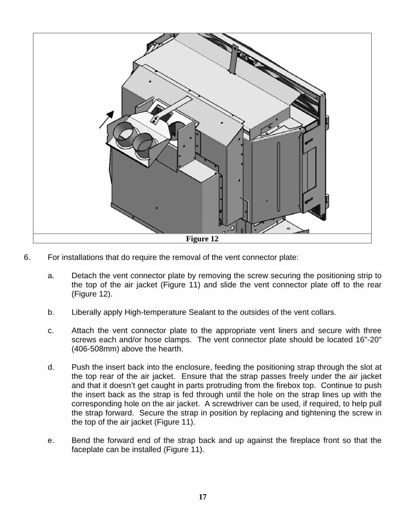
Figure 12
6. For installations that do require the removal of the vent connector plate:
a. Detach the vent connector plate by removing the screw securing the positioning strip to the top of the air jacket (Figure 11) and slide the vent connector plate off to the rear (Figure 12).
b. Liberally apply High-temperature Sealant to the outsides of the vent collars.
c. Attach the vent connector plate to the appropriate vent liners and secure with three
screws each and/or hose clamps. The vent connector plate should be located 16"-20" (406-508mm) above the hearth.
d. Push the insert back into the enclosure, feeding the positioning strap through the slot at
the top rear of the air jacket. Ensure that the strap passes freely under the air jacket and that it doesn’t get caught in parts protruding from the firebox top. Continue to push the insert back as the strap is fed through until the hole on the strap lines up with the corresponding hole on the air jacket. A screwdriver can be used, if required, to help pull the strap forward. Secure the strap in position by replacing and tightening the screw in the top of the air jacket (Figure 11).
e. Bend the forward end of the strap back and up against the fireplace front so that the
faceplate can be installed (Figure 11).
17
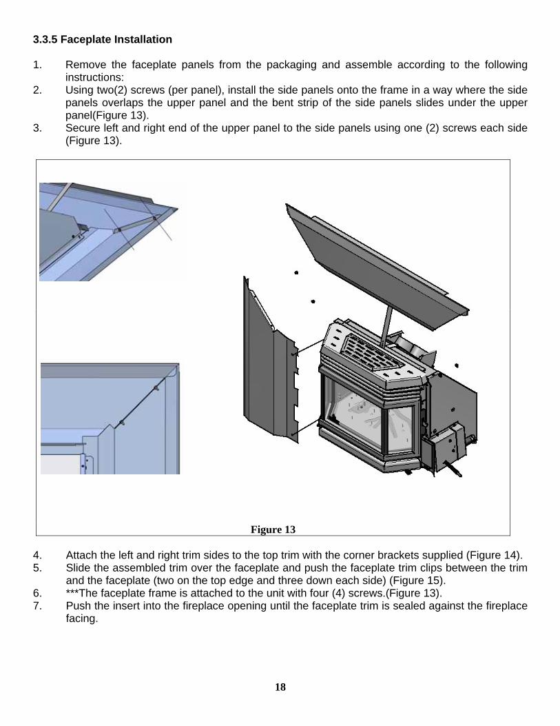
3.3.5 Faceplate Installation 1. Remove the faceplate panels from the packaging and assemble according to the following
instructions: 2. Using two(2) screws (per panel), install the side panels onto the frame in a way where the side
panels overlaps the upper panel and the bent strip of the side panels slides under the upper panel(Figure 13).
3. Secure left and right end of the upper panel to the side panels using one (2) screws each side (Figure 13).
Figure 13
4. Attach the left and right trim sides to the top trim with the corner brackets supplied (Figure 14). 5. Slide the assembled trim over the faceplate and push the faceplate trim clips between the trim
and the faceplate (two on the top edge and three down each side) (Figure 15). 6. ***The faceplate frame is attached to the unit with four (4) screws.(Figure 13). 7. Push the insert into the fireplace opening until the faceplate trim is sealed against the fireplace
facing.
18
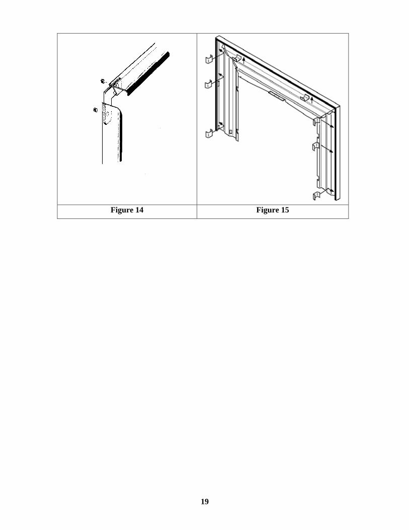
Figure 14 Figure 15
19

3.3.6 Fire box components installation 3.3.6.1 Installing logs Note:If the pictures in this section are not clear enough, you may see them in color by downloading
this owner’s manual via Osburn web site at www.osburn-mfg.com. Step 1: Place the rear log at the far end of the firebox and move it back slightly toward the front until
it is blocked by the stoppers located at each end of the burner.
Step 2: Place the smallest log on the pin located on the burner tray.
20
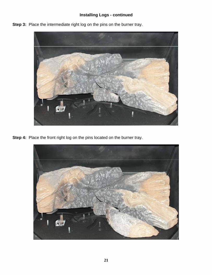
Installing Logs - continued Step 3: Place the intermediate right log on the pins on the burner tray.
Step 4: Place the front right log on the pins located on the burner tray.
21
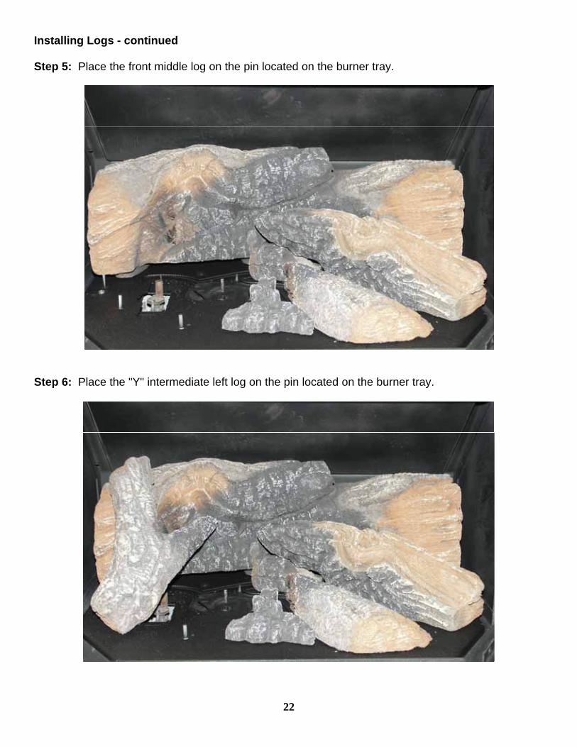
Installing Logs - continued Step 5: Place the front middle log on the pin located on the burner tray.
Step 6: Place the "Y" intermediate left log on the pin located on the burner tray.
22

Step 7: Place the front left log on the pins located on the burner tray.
3.3.6.2 Installing or Removing the Glass Door The door is hinged on the left side, insert door hinges (on door) onto door pins (on unit) and swing shut, fasten the latch to secure the door. Removal is reverse order. Warning: Do not operate the appliance with the glass front removed, cracked or broken. Replacement of the glass should be done by a licensed qualified service person.
Figure 16 Door latch
Figure 17 Handle to Unlatch the door
23
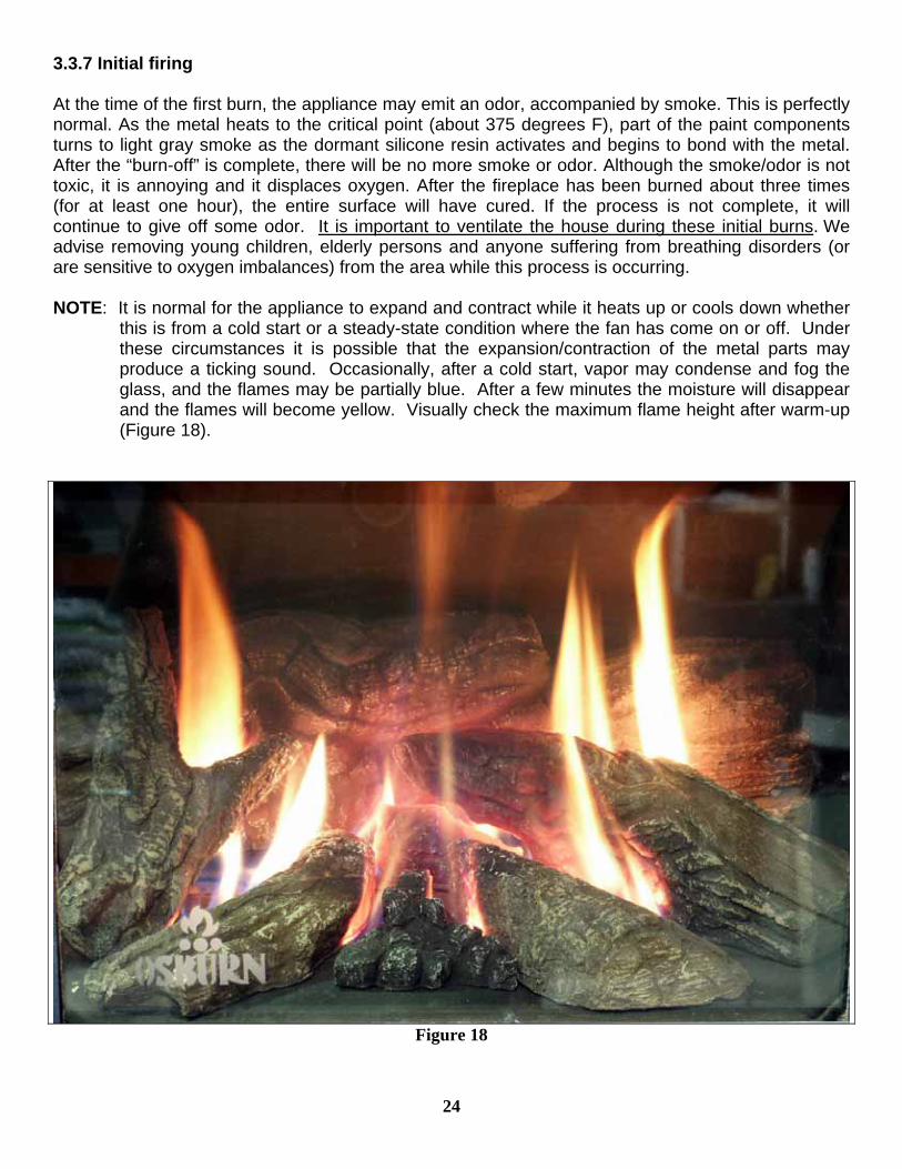
3.3.7 Initial firing At the time of the first burn, the appliance may emit an odor, accompanied by smoke. This is perfectly normal. As the metal heats to the critical point (about 375 degrees F), part of the paint components turns to light gray smoke as the dormant silicone resin activates and begins to bond with the metal. After the “burn-off” is complete, there will be no more smoke or odor. Although the smoke/odor is not toxic, it is annoying and it displaces oxygen. After the fireplace has been burned about three times (for at least one hour), the entire surface will have cured. If the process is not complete, it will continue to give off some odor. It is important to ventilate the house during these initial burns. We advise removing young children, elderly persons and anyone suffering from breathing disorders (or are sensitive to oxygen imbalances) from the area while this process is occurring. NOTE: It is normal for the appliance to expand and contract while it heats up or cools down whether
this is from a cold start or a steady-state condition where the fan has come on or off. Under these circumstances it is possible that the expansion/contraction of the metal parts may produce a ticking sound. Occasionally, after a cold start, vapor may condense and fog the glass, and the flames may be partially blue. After a few minutes the moisture will disappear and the flames will become yellow. Visually check the maximum flame height after warm-up (Figure 18).
Figure 18
24
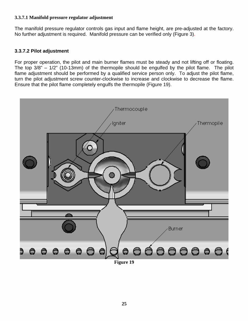
3.3.7.1 Manifold pressure regulator adjustment The manifold pressure regulator controls gas input and flame height, are pre-adjusted at the factory. No further adjustment is required. Manifold pressure can be verified only (Figure 3). 3.3.7.2 Pilot adjustment For proper operation, the pilot and main burner flames must be steady and not lifting off or floating. The top 3/8” – 1/2” (10-13mm) of the thermopile should be engulfed by the pilot flame. The pilot flame adjustment should be performed by a qualified service person only. To adjust the pilot flame, turn the pilot adjustment screw counter-clockwise to increase and clockwise to decrease the flame. Ensure that the pilot flame completely engulfs the thermopile (Figure 19).
Figure 19
25
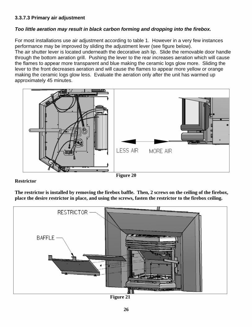
3.3.7.3 Primary air adjustment Too little aeration may result in black carbon forming and dropping into the firebox. For most installations use air adjustment according to table 1. However in a very few instances performance may be improved by sliding the adjustment lever (see figure below). The air shutter lever is located underneath the decorative ash lip. Slide the removable door handle through the bottom aeration grill. Pushing the lever to the rear increases aeration which will cause the flames to appear more transparent and blue making the ceramic logs glow more. Sliding the lever to the front decreases aeration and will cause the flames to appear more yellow or orange making the ceramic logs glow less. Evaluate the aeration only after the unit has warmed up approximately 45 minutes.
Figure 20 Restrictor The restrictor is installed by removing the firebox baffle. Then, 2 screws on the ceiling of the firebox, place the desire restrictor in place, and using the screws, fasten the restrictor to the firebox ceiling.
Figure 21
26
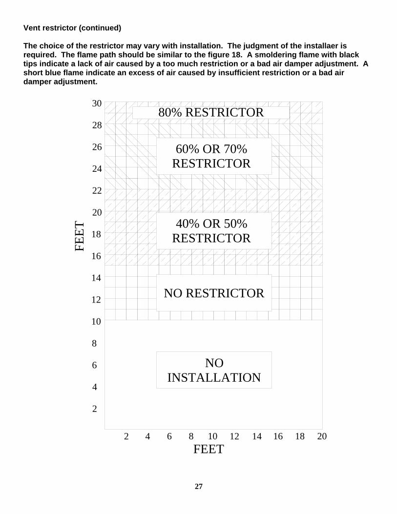
Vent restrictor (continued) The choice of the restrictor may vary with installation. The judgment of the installaer is required. The flame path should be similar to the figure 18. A smoldering flame with black tips indicate a lack of air caused by a too much restriction or a bad air damper adjustment. A short blue flame indicate an excess of air caused by insufficient restriction or a bad air damper adjustment.
2016 1812108 14
30
26
28
24
22
18
16
20
12
10
4
6
8
14
642
2
NO INSTALLATION
FEET
FEET
NO RESTRICTOR
40% OR 50% RESTRICTOR
60% OR 70% RESTRICTOR
80% RESTRICTOR
27
28
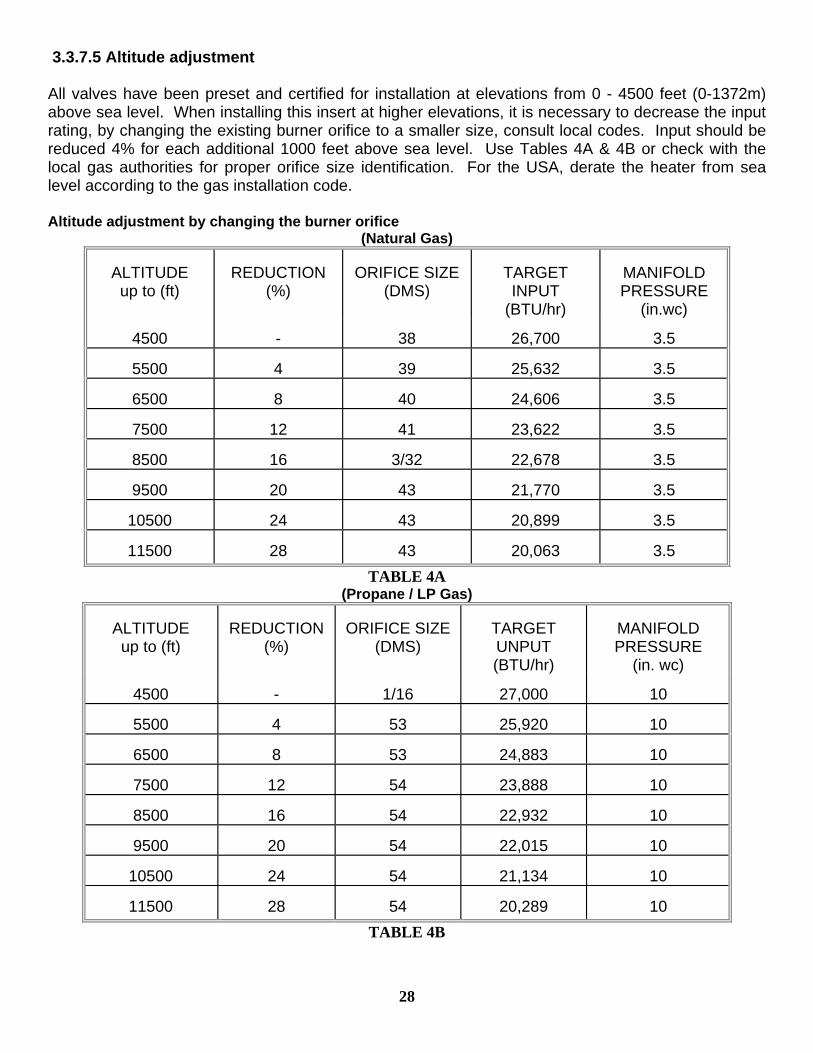
3.3.7.5 Altitude adjustment All valves have been preset and certified for installation at elevations from 0 - 4500 feet (0-1372m) above sea level. When installing this insert at higher elevations, it is necessary to decrease the input rating, by changing the existing burner orifice to a smaller size, consult local codes. Input should be reduced 4% for each additional 1000 feet above sea level. Use Tables 4A & 4B or check with the local gas authorities for proper orifice size identification. For the USA, derate the heater from sea level according to the gas installation code. Altitude adjustment by changing the burner orifice
(Natural Gas)
ALTITUDE up to (ft)
REDUCTION
(%)
ORIFICE SIZE
(DMS)
TARGET INPUT
(BTU/hr)
MANIFOLD PRESSURE
(in.wc)
4500
-
38
26,700
3.5
5500
4
39
25,632
3.5
6500
8
40
24,606
3.5
7500
12
41
23,622
3.5
8500
16
3/32
22,678
3.5
9500
20
43
21,770
3.5
10500
24
43
20,899
3.5
11500
28
43
20,063
3.5 TABLE 4A
(Propane / LP Gas)
ALTITUDE up to (ft)
REDUCTION
(%)
ORIFICE SIZE
(DMS)
TARGET UNPUT (BTU/hr)
MANIFOLD PRESSURE
(in. wc)
4500
-
1/16
27,000
10
5500
4
53
25,920
10
6500
8
53
24,883
10
7500
12
54
23,888
10
8500
16
54
22,932
10
9500
20
54
22,015
10
10500
24
54
21,134
10
11500
28
54
20,289
10 TABLE 4B
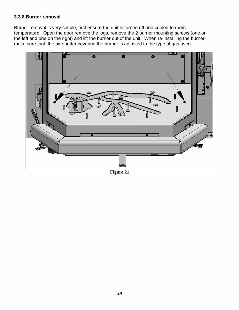
3.3.8 Burner removal Burner removal is very simple, first ensure the unit is turned off and cooled to room temperature. Open the door remove the logs, remove the 2 burner mounting screws (one on the left and one on the right) and lift the burner out of the unit. When re-installing the burner make sure that the air shutter covering the burner is adjusted to the type of gas used.
Figure 21
29
30
3.3.9 Field Conversions Turn off the gas supply to the unit and allow the heater to cool for up to 30 minutes before servicing. The following procedure is to be performed by qualified service personnel ONLY. Local building codes and installation codes must be adhered to.
1. Remove the door carefully and set it in a safe place away from traffic areas. 2. Remove the logs and store in a safe place. 3. Remove the two Phillips head screws in the centre of the burner sides. 4. Remove the burner tray assembly by lifting it up and towards you, then out of the
firebox. 5. In order to convert the pilot’s orifice, you need to unscrew nut “B” counterclockwise by
1/4 of a turn. To convert from natural gas to liquid propane, slide the selector plate “A” in order to see letters “P”. To convert from liquid propane to natural gas, slide the selector plate “A” in order to see letter “NAT”. Tighten nut « B»
6. Remove the burner orifice by unscrewing it from the 90-degree elbow and passing it through the air shutter plate.
7. To convert valve from natural gas to liquid propane, unscrew the blue screw on the HI-LO button and replace with the red screw. Apply the fuel conversion sticker.
8. Re-install the burner assembly and log set. 9. Set air shutter as per table 1 and instructions in 3.3.7.3. 10. Reinstall components in reverse order. 11. Fill out the conversion label and install it near the “ CAUTION: HOT WHILE IN
OPERATION “ label.
31
4.0 MAINTENANCE 4.1 Maintenance safety Turn off the gas to the main burner and allow the heater to cool for up to 30 minutes before servicing. Service and repair should be done by a qualified service person. The appliance should be inspected before use and at least annually by a professional service technician. More frequent cleaning may be required due to excessive lint from carpeting, bedding material, etc. It is important that the access door compartment, burner, and circulating air passageways be kept clean to provide for adequate combustion and ventilation airflow. Do not substitute materials or use components other than factory supplied. 4.2 Recommended service 1. Examine the venting system periodically.
2. Visually check the burner and pilot flames occasionally. Visually inspect height and color of
flames.
3. Clean the glass as needed. See section 4.3 for instructions on glass cleaning.
4. Have the appliance inspected annually by a professional service technician.
5. Clean the appliance regularly.
Annual service: An annual service call should take between 1 – 2 hours. Start by disassembling the unit; take off the glass and remove all the logs, embers, burner, and fan. A small toothbrush is a handy tool for cleaning the fan. Loosen all the debris on the fan blades and vacuum it off. Vacuum the whole firebox and all the air passages. Clean the burner, pilot orifice, main orifice, logs, etc. After everything is clean, check all the connections and the chassis ground and reassemble. Fire up the unit and check the electrical readings of the thermopile/thermocouple. Clean the glass. Check the gas pressure. Check the draft (the venting system should also be checked). 4.3 Glass cleaning The inside of the glass may require periodic cleaning to remove deposits left from impurities in the gas and combustion air. For best results, use a ceramic glass cleaner or polish. A suitable cleaner is available from your dealer. Avoid the use of ammonia based cleaners such as Windex®. Do not clean while hot. Do not use abrasive cleaners. Make sure you clean off the white film on the fireplace glass as soon as possible – otherwise the glass may deteriorate.
32
4.4 Cleaning of gold plated surfaces Take special care and DO NOT use chemical or abrasive cleaners. Wipe only with a soft damp cotton cloth to maintain original brilliance. Do not clean plated surfaces when they are still hot. CAUTION: Vigorous wiping may damage the gold finish. 4.5 Burner & pilot cleaning Periodic cleaning is necessary for proper operation. Refer to section 4.8, remove the burner, and check that the burner orifice is clean. Visually inspect the pilot. Brush or blow away any dust, lint, or foreign debris. If the pilot orifice is plugged, disassembly may be required to remove any foreign material from the orifice or tubing. When the appliance is back in service, check the pilot flame pattern with the figures in Section 3.3.7. For re-lighting, refer to the lighting instructions in Section 2.2. 4.6 Fan replacement & electrical schematic “Caution: Label all wires prior to disconnection when servicing controls. Wiring errors can cause improper and dangerous operation. Verify proper operation after servicing.
1. Disconnect power from the unit. 2. Remove the glass door. 3. Remove the burner. 4. Remove the rear baffle of the combustion chamber. 5. Remove back of the combustion chamber. 6. Lift the blower to unclip it. 7. Identify and Remove the wires from the blower.
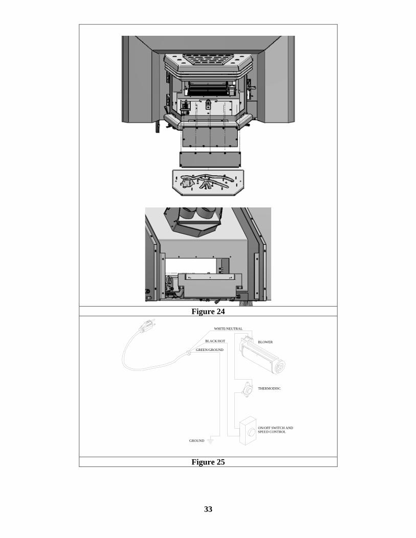
Figure 24
GROUND
ON/OFF SWITCH ANDSPEED CONTROL
THERMODISC
BLOWER
WHITE/NEUTRAL
BLACK/HOT
GREEN/GROUND
Figure 25
33
34
5.0 TROUBLE SHOOTING SYMPTOM POSSIBLE CAUSE CORRECTIVE ACTION
I. Pilot will not light after repeated triggering of the piezo ignition button
A. No spark at electrode (weak or not heat source for pilot ignition)
1. Improper ignition 1. Align the electrode with 1/8” (3mm) gap to pilot hood
2. Poor connections at igniter and ignition electrode
2. Reconnect if loose
3. Broken ceramic cover on ignition electrode
3. Replace pilot assembly
4. Defective piezo igniter 4. Replace piezo igniter B. No gas or low gas pressure 1. Gas line shut off(s) may not be
turned on 1. Turn of shut-off valves
2. No gas supply (LPG) 2. Check propane tank; you may be out of fuel
3. Air in gas lines 3. Purge gas lines 4. Gas lines may not be
connected 4. Connect all gas lines
5. Low pressure may be caused by bent line
5. Check for a kinked line
6. Valve control knob not fully depressed in “PILOT” position
6. Fully depress control knob
II. Pilot will not stay lit after following the lighting instructions
A. Thermocouple / Valve
1. Weak or improperly located pilot flame
1. Adjust and clean pilot. The flame must impinge on or engulf the thermocouple, as shown on figure 19.
2. Defective thermocouple 2. Have the thermostat contacts open and pilot lit with the knob turned to the "Pilot" position. Reading should be a minimum of 18 mV for a new thermocouple, if the reading is less than 18mV replace the thermocouple.
3. Thermocouple not installed properly
3. Make sure all wire connections at the gas valve terminals are tight and the thermocouple is fully inserted into the mounting bracket
4. Open wire connection in pilot circuit
4. Check wire continuity and connections in the pilot circuit
35
III. Main burner will not light A. Valve / Switches
1. Valve control off 1. Turn to “ON” position 2. Blockage at the burner (line,
orifice, or ports) 2. Check and clean
3. Defective wall switch or thermostat
3. Conduct a continuity test or jumper wire test and replace if defective
4. Defective wiring or connections 4. Conduct a test with a jumper wire and repair as required
5. Excessive length of thermostat wire from valve to wall switch or thermostat
5. Reduce wire length to less than 100 feet or increase wire size
6. Wall switch or thermostat incorrectly wired
6. Wire correctly
7. Defective Valve 7. Turn valve and “ON/OFF” switch to the “ON” position. Check with millivolt meter at terminals TP-TH & TH. Millivolt meter should read greater then 460 millivolts. If the reading is OK and the burner does not come on, replace the gas valve
8. Thermopile may not be generating sufficient voltage (460 mV)
8. Recheck using the millivolt meter. The pilot flame may not be high enough for the flame to properly engulf the thermopile. If so, adjust and reset. If voltage is still insufficient, replace thermopile
9. Wall switch, thermostat, or wires are defective
9. Follow previous corrective action, check switch and wiring. Replace where defective
10. Defective spill switch (B-Vent) 10. Check continuity and replace if defective 1. Flame impingement on logs 1. Adjust the log set to avoid direct flame
impingement. Follow log placement instructions
IV. Soot deposits on glass
2. Improper primary air setting 2. Open aeration shutter more. Foreign material impeding burner 3. Ensure that no foreign material blocks
burner flame ports
3. Air inlet blocked or restricted 4. Clean air inlets 4. Vent system is restricted or
inadequate
V. Flame burns blue and lifts off burner
1. Insufficient combustion air being supplied
1. Ensure that no foreign material blocks air inlets and that the burner shutter is correctly adjusted. Ensure the vent is adequate
2. Manifold pressure set too high 2. Check manifold pressure 3. Vent system restricted 3. Check vent system
VI. Flames impinge on firebox top
1. Vent system is restricted or inadequate
1. Correct flue as required
2. Manifold pressure too high 2. Check manifold pressure as required
36
6.0 REPLACEMENT PARTS When requesting service or replacement parts, refer to your dealer. The following information’s will be asked for; the model name “Britania insert”, the type of gas used, serial number and proof of purchase. The damaged parts must be replaced by Osburn genuine parts. You can consult the spare parts list on our website at www.osburn-mfg.com or contact your Osburn dealer.
37
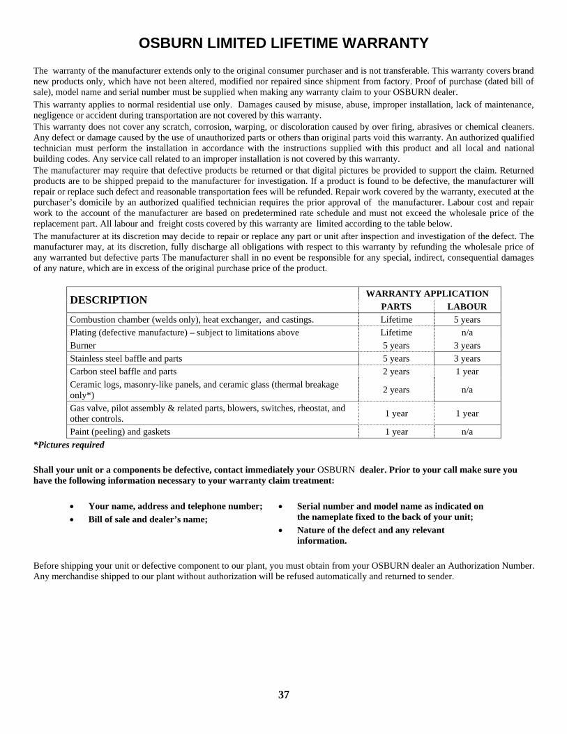
OSBURN LIMITED LIFETIME WARRANTY The warranty of the manufacturer extends only to the original consumer purchaser and is not transferable. This warranty covers brand new products only, which have not been altered, modified nor repaired since shipment from factory. Proof of purchase (dated bill of sale), model name and serial number must be supplied when making any warranty claim to your OSBURN dealer. This warranty applies to normal residential use only. Damages caused by misuse, abuse, improper installation, lack of maintenance, negligence or accident during transportation are not covered by this warranty. This warranty does not cover any scratch, corrosion, warping, or discoloration caused by over firing, abrasives or chemical cleaners. Any defect or damage caused by the use of unauthorized parts or others than original parts void this warranty. An authorized qualified technician must perform the installation in accordance with the instructions supplied with this product and all local and national building codes. Any service call related to an improper installation is not covered by this warranty. The manufacturer may require that defective products be returned or that digital pictures be provided to support the claim. Returned products are to be shipped prepaid to the manufacturer for investigation. If a product is found to be defective, the manufacturer will repair or replace such defect and reasonable transportation fees will be refunded. Repair work covered by the warranty, executed at the purchaser’s domicile by an authorized qualified technician requires the prior approval of the manufacturer. Labour cost and repair work to the account of the manufacturer are based on predetermined rate schedule and must not exceed the wholesale price of the replacement part. All labour and freight costs covered by this warranty are limited according to the table below. The manufacturer at its discretion may decide to repair or replace any part or unit after inspection and investigation of the defect. The manufacturer may, at its discretion, fully discharge all obligations with respect to this warranty by refunding the wholesale price of any warranted but defective parts The manufacturer shall in no event be responsible for any special, indirect, consequential damages of any nature, which are in excess of the original purchase price of the product.
WARRANTY APPLICATION DESCRIPTION PARTS LABOUR Combustion chamber (welds only), heat exchanger, and castings. Lifetime 5 years Plating (defective manufacture) – subject to limitations above Lifetime n/a Burner 5 years 3 years Stainless steel baffle and parts 5 years 3 years Carbon steel baffle and parts 2 years 1 year Ceramic logs, masonry-like panels, and ceramic glass (thermal breakage only*) 2 years n/a
Gas valve, pilot assembly & related parts, blowers, switches, rheostat, and other controls. 1 year 1 year
Paint (peeling) and gaskets 1 year n/a *Pictures required Shall your unit or a components be defective, contact immediately your OSBURN dealer. Prior to your call make sure you have the following information necessary to your warranty claim treatment:
• Your name, address and telephone number; • Bill of sale and dealer’s name;
• Serial number and model name as indicated on the nameplate fixed to the back of your unit;
• Nature of the defect and any relevant information.
Before shipping your unit or defective component to our plant, you must obtain from your OSBURN dealer an Authorization Number. Any merchandise shipped to our plant without authorization will be refused automatically and returned to sender.