Embed Size (px)
Citation preview

Bring Your Own Water Treatment System – Pump Driven Configuration
www.ewb-jsc.org
Page 1 of 84
Bring Your Own Water Treatment System –
Pump Driven Configuration
Build, Operation, and Monitoring Manual
Trae Su Propia Sistema- Tratamiento de Agua Bombee Configuración Conducida
Manual de Operaciones
Bring Your Own Water Treatment System – Pump Driven Configuration
www.ewb-jsc.org
Page 2 of 84
Table of Contents
1.0 Background ........................................................................................................................ 3
2.0 System Description ........................................................................................................... 4
3.0 Operation Procedures ...................................................................................................... 8
3.1 Water Treatment ............................................................................................................... 8
3.2 BYOW Operational Placard ........................................................................................... 10
3.3 Design of Ultraviolet light electronic circuit .................................................................. 11
4.0 Maintenance Procedures ............................................................................................... 13
4.1 Backwashing the Rapid Sand Filter ............................................................................... 13
4.2 Draining the Roughing Filter ......................................................................................... 14
4.5 Changing the UV Light Bulb ......................................................................................... 15
5.0 Build Procedures ............................................................................................................. 17
5.1 Plastic Drum Sand Filter ................................................................................................ 17
Plastic Drum Gravel Filter ........................................................................................................ 45
Bulkhead Build ......................................................................................................................... 60
6.0 Assessment and Monitoring Plan ................................................................................. 63
6.1 Water Quality Monitoring .............................................................................................. 63
Usage Monitoring ..................................................................................................................... 69
Public Health Monitoring ......................................................................................................... 72
EWB-USA provided Public Health Assessment Forms ........................................................... 73

Bring Your Own Water Treatment System – Pump Driven Configuration
www.ewb-jsc.org
Page 3 of 84
1.0 Background
Over a billion people in the world lack access to safe drinking water. While numerous technological, medical, and educational solutions have been implemented for the benefit of disadvantaged communities, there is no ‘magic bullet’. Instead, development agencies must partner directly with these communities to address their public health needs through appropriate technology solutions backed up by education and assessment. The “Bring Your Own Water (BYOW) Treatment System” developed by Engineers Without Borders-USA is uniquely designed to address the water treatment requirements of rural communities. The BYOW system consists of a gravity-fed roughing filter, rapid sand filter, and solar-panel powered electrical ultraviolet irradiation system. The BYOW system treats water collected in containers by local residents. A key component is a self-filling tank for backwashing of the filter. The system treats water at a rate of approximately 10 liters per minute, and can provide up to 8,400 liters of treated water per day. The BYOW system performed successfully in long term tests in Houston, Texas, where wastewater (over 70 NTU turbidity, 3000 CFU / ml E. Coli) was inputted and the effluent water was significantly cleaner (less than one NTU, 0-2 CFU / ml E. Coli). The BYOW system has the potential to be successfully replicated around the world where communities have similar social and economic constraints and water treatment requirements.

Bring Your Own Water Treatment System – Pump Driven Configuration
www.ewb-jsc.org
Page 4 of 84
2.0 System Description
Water-borne disease is a leading cause of illness in the developing world, contributing to the death of 15 million children every year, on average. However, there has yet to be developed a catch-all technology that can successfully be implemented in most developing communities. The BYOW system developed by several EWB-USA chapters is a unique assembly of previously proven water-treatment technologies that directly addresses the specific constraints and requirements of rural communities. This system and its subsequent iterations have the potential to directly address the biggest public health concern in many communities around the world. This project directly addresses several of the United Nations Millennium Development Goals (MDG), including reducing child mortality, improving maternal health, combating disease, ensuring environmental sustainability, and developing a global partnership for development. The BYOW Treatment System combines several water treatment approaches. The first treatment step in the system is the gravel roughing filter. Incoming water enters the roughing filter from the bottom of the inclined drum and flows upward through gravel media with and average diameter of 1”. As the water travels through the gravel, gravity causes entrained sediment to sink downward below the distribution arms into a sediment catchment basin. Next to this roughing filter is a backwash tank with a valve that automatically diverts a portion of the input water and stores it for later backwash of the rapid sand filter. The bulk of the water is piped downhill, with the vertical drop of 10-15 vertical feet, providing pressure for the Plastic Drum Sand Filter (PDSF). The PSDF, a rapid sand filter, is built from a watertight UN standard 55 gallon drum with a removable lid. It is designed to operate under pressure to increase filtration speed. In this implementation, the PDSF operates at a maximum pressure of 14 feet of water (6 psi, 41 kPa). Unfiltered water enters near the top of the filter drum and is distributed across the top of the media bed by perforated arms. The cross-shaped distribution arm is mounted on a PVC union fitting that allows the arm to swing upward and out of the way to facilitate maintenance access to the media bed. Water is forced through the media by pressure from the column of water above it, removing particulates and bacteria. Because system pressurization is provided by each bucket of water added, the amount of treated water delivered to the user can be no greater than the amount introduced. Additionally, the water is provided within minutes, because the sand filter is already primed and pressurized with water added by previous users. The PDSF in the BYOW system differs from typical sand filters and borrows principles from both rapid and slow sand filter designs. The biggest departure from usual design is the minimal pretreatment before filtration. While typical filters have pretreatment processes or other types of influent control, the PDSF influent is quite variable with the only pretreatment process being the roughing filter. The predictable
Bring Your Own Water Treatment System – Pump Driven Configuration
www.ewb-jsc.org
Page 5 of 84
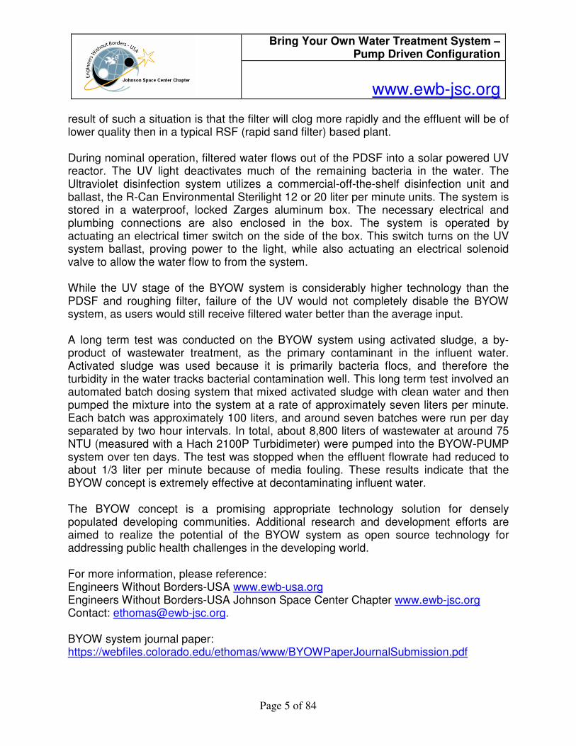
result of such a situation is that the filter will clog more rapidly and the effluent will be of lower quality then in a typical RSF (rapid sand filter) based plant. During nominal operation, filtered water flows out of the PDSF into a solar powered UV reactor. The UV light deactivates much of the remaining bacteria in the water. The Ultraviolet disinfection system utilizes a commercial-off-the-shelf disinfection unit and ballast, the R-Can Environmental Sterilight 12 or 20 liter per minute units. The system is stored in a waterproof, locked Zarges aluminum box. The necessary electrical and plumbing connections are also enclosed in the box. The system is operated by actuating an electrical timer switch on the side of the box. This switch turns on the UV system ballast, proving power to the light, while also actuating an electrical solenoid valve to allow the water flow to from the system. While the UV stage of the BYOW system is considerably higher technology than the PDSF and roughing filter, failure of the UV would not completely disable the BYOW system, as users would still receive filtered water better than the average input. A long term test was conducted on the BYOW system using activated sludge, a by-product of wastewater treatment, as the primary contaminant in the influent water. Activated sludge was used because it is primarily bacteria flocs, and therefore the turbidity in the water tracks bacterial contamination well. This long term test involved an automated batch dosing system that mixed activated sludge with clean water and then pumped the mixture into the system at a rate of approximately seven liters per minute. Each batch was approximately 100 liters, and around seven batches were run per day separated by two hour intervals. In total, about 8,800 liters of wastewater at around 75 NTU (measured with a Hach 2100P Turbidimeter) were pumped into the BYOW-PUMP system over ten days. The test was stopped when the effluent flowrate had reduced to about 1/3 liter per minute because of media fouling. These results indicate that the BYOW concept is extremely effective at decontaminating influent water. The BYOW concept is a promising appropriate technology solution for densely populated developing communities. Additional research and development efforts are aimed to realize the potential of the BYOW system as open source technology for addressing public health challenges in the developing world.
For more information, please reference: Engineers Without Borders-USA www.ewb-usa.org Engineers Without Borders-USA Johnson Space Center Chapter www.ewb-jsc.org Contact: [email protected]. BYOW system journal paper: https://webfiles.colorado.edu/ethomas/www/BYOWPaperJournalSubmission.pdf
Bring Your Own Water Treatment System – Pump Driven Configuration
www.ewb-jsc.org
Page 6 of 84
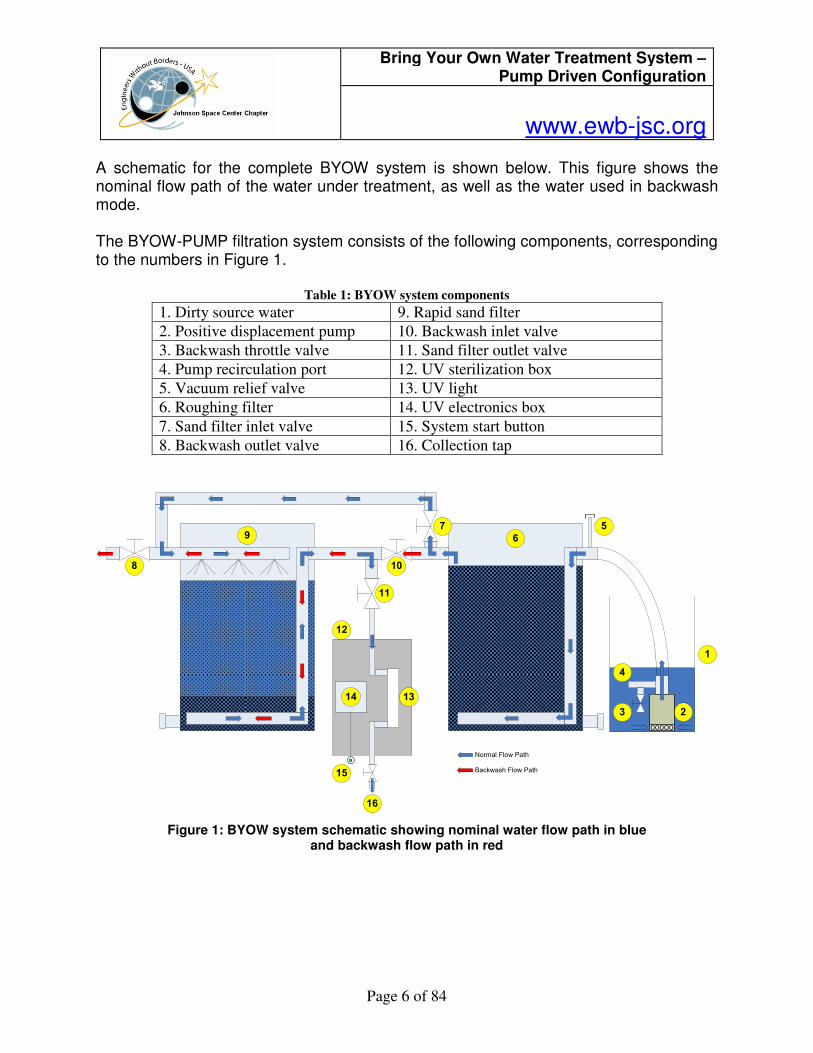
A schematic for the complete BYOW system is shown below. This figure shows the nominal flow path of the water under treatment, as well as the water used in backwash mode.
The BYOW-PUMP filtration system consists of the following components, corresponding to the numbers in Figure 1.
Table 1: BYOW system components
1. Dirty source water 9. Rapid sand filter
2. Positive displacement pump 10. Backwash inlet valve
3. Backwash throttle valve 11. Sand filter outlet valve
4. Pump recirculation port 12. UV sterilization box
5. Vacuum relief valve 13. UV light
6. Roughing filter 14. UV electronics box
7. Sand filter inlet valve 15. System start button
8. Backwash outlet valve 16. Collection tap
1
2
4
5
6
7
8
9
10
11
12
13
15
Normal Flow Path
Backwash Flow Path
3
16
14
Figure 1: BYOW system schematic showing nominal water flow path in blue and backwash flow path in red
Bring Your Own Water Treatment System – Pump Driven Configuration
www.ewb-jsc.org
Page 7 of 84
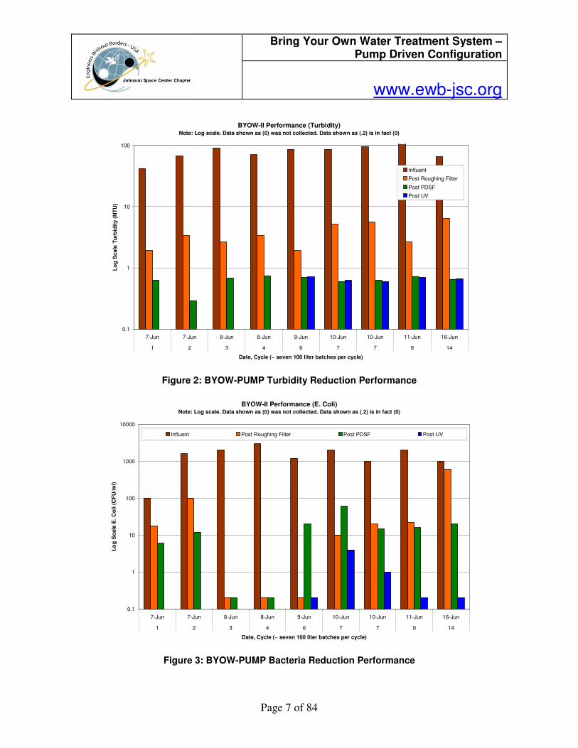
Figure 2: BYOW-PUMP Turbidity Reduction Performance
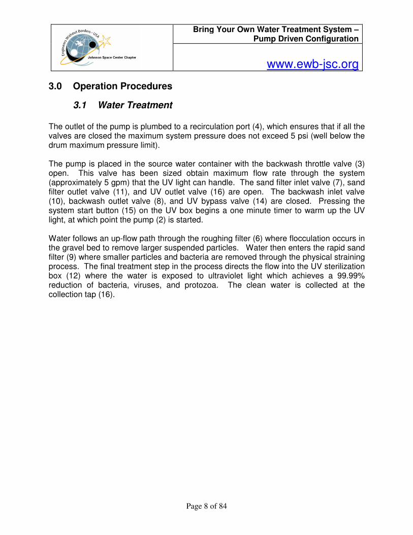
BYOW-II Performance (E. Coli)Note: Log scale. Data shown as (0) was not collected. Data shown as (.2) is in fact (0)
0.1
1
10
100
1000
10000
7-Jun 7-Jun 8-Jun 8-Jun 9-Jun 10-Jun 10-Jun 11-Jun 16-Jun
1 2 3 4 6 7 7 9 14
Date, Cycle (~ seven 100 liter batches per cycle)
Lo
g S
cale
E. C
oli (
CF
U/m
l)
Influent Post Roughing Filter Post PDSF Post UV
Figure 3: BYOW-PUMP Bacteria Reduction Performance
BYOW-II Performance (Turbidity)Note: Log scale. Data shown as (0) was not collected. Data shown as (.2) is in fact (0)
0.1
1
10
100
7-Jun 7-Jun 8-Jun 8-Jun 9-Jun 10-Jun 10-Jun 11-Jun 16-Jun
1 2 3 4 6 7 7 9 14
Date, Cycle (~ seven 100 liter batches per cycle)
Lo
g S
ca
le T
urb
idit
y (
NT
U)
Influent
Post Roughing Filter
Post PDSF
Post UV
Bring Your Own Water Treatment System – Pump Driven Configuration
www.ewb-jsc.org
Page 8 of 84
3.0 Operation Procedures
3.1 Water Treatment
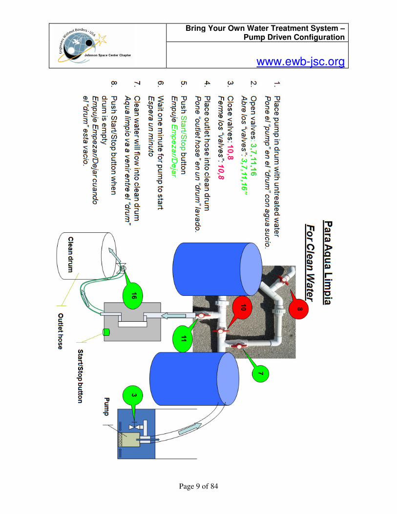
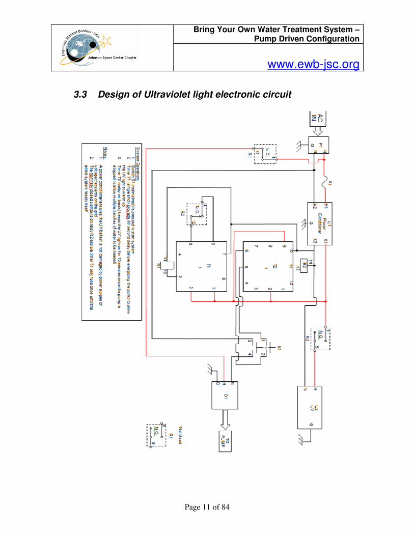
The outlet of the pump is plumbed to a recirculation port (4), which ensures that if all the valves are closed the maximum system pressure does not exceed 5 psi (well below the drum maximum pressure limit). The pump is placed in the source water container with the backwash throttle valve (3) open. This valve has been sized obtain maximum flow rate through the system (approximately 5 gpm) that the UV light can handle. The sand filter inlet valve (7), sand filter outlet valve (11), and UV outlet valve (16) are open. The backwash inlet valve (10), backwash outlet valve (8), and UV bypass valve (14) are closed. Pressing the system start button (15) on the UV box begins a one minute timer to warm up the UV light, at which point the pump (2) is started. Water follows an up-flow path through the roughing filter (6) where flocculation occurs in the gravel bed to remove larger suspended particles. Water then enters the rapid sand filter (9) where smaller particles and bacteria are removed through the physical straining process. The final treatment step in the process directs the flow into the UV sterilization box (12) where the water is exposed to ultraviolet light which achieves a 99.99% reduction of bacteria, viruses, and protozoa. The clean water is collected at the collection tap (16).
Bring Your Own Water Treatment System – Pump Driven Configuration
www.ewb-jsc.org
Page 9 of 84
Bring Your Own Water Treatment System – Pump Driven Configuration
www.ewb-jsc.org
Page 10 of 84
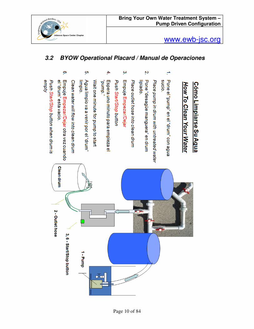
3.2 BYOW Operational Placard / Manual de Operaciones
Bring Your Own Water Treatment System – Pump Driven Configuration
www.ewb-jsc.org
Page 11 of 84
3.3 Design of Ultraviolet light electronic circuit
Bring Your Own Water Treatment System – Pump Driven Configuration
www.ewb-jsc.org
Page 12 of 84
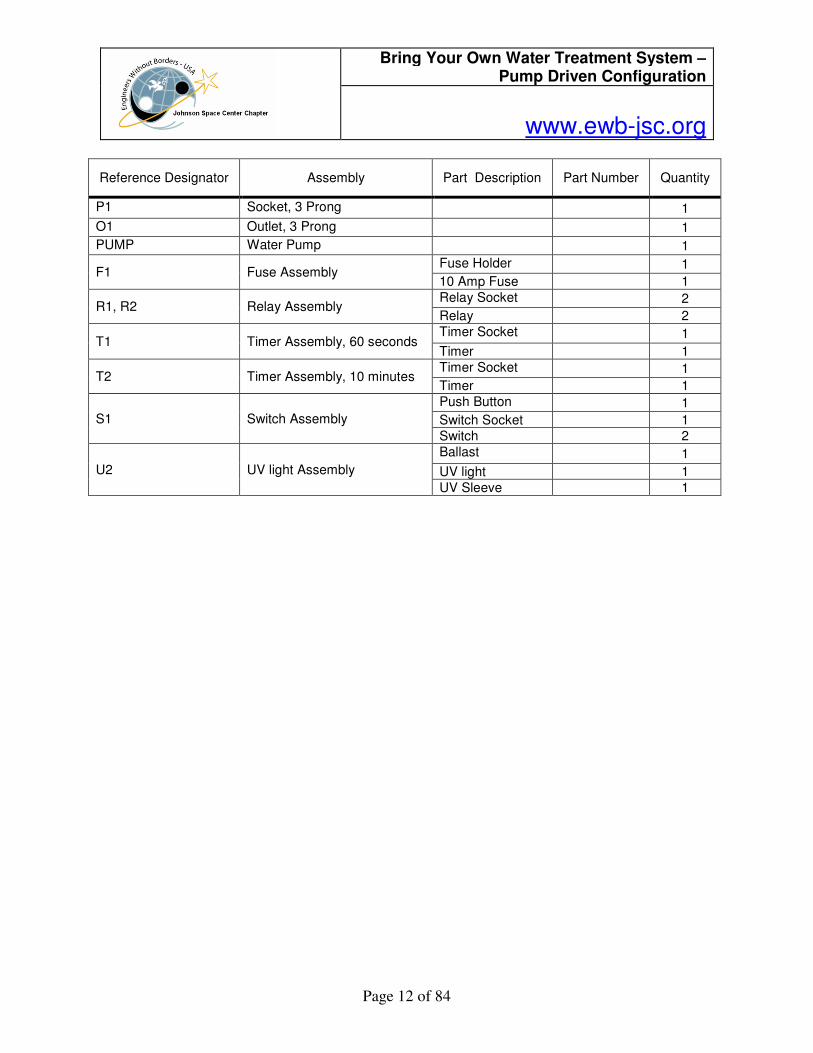
Reference Designator Assembly Part Description Part Number Quantity
P1 Socket, 3 Prong 1
O1 Outlet, 3 Prong 1
PUMP Water Pump 1
F1 Fuse Assembly Fuse Holder 1
10 Amp Fuse 1
R1, R2 Relay Assembly Relay Socket 2
Relay 2
T1 Timer Assembly, 60 seconds Timer Socket 1
Timer 1
T2 Timer Assembly, 10 minutes Timer Socket 1
Timer 1
S1 Switch Assembly
Push Button 1
Switch Socket 1
Switch 2
U2 UV light Assembly
Ballast 1
UV light 1
UV Sleeve 1
Bring Your Own Water Treatment System – Pump Driven Configuration
www.ewb-jsc.org
Page 13 of 84
4.0 Maintenance Procedures
4.1 Backwashing the Rapid Sand Filter
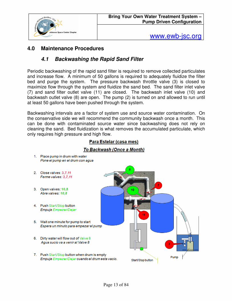
Periodic backwashing of the rapid sand filter is required to remove collected particulates and increase flow. A minimum of 50 gallons is required to adequately fluidize the filter bed and purge the system. The pressure backwash throttle valve (3) is closed to maximize flow through the system and fluidize the sand bed. The sand filter inlet valve (7) and sand filter outlet valve (11) are closed. The backwash inlet valve (10) and backwash outlet valve (8) are open. The pump (2) is turned on and allowed to run until at least 50 gallons have been pushed through the system. Backwashing intervals are a factor of system use and source water contamination. On the conservative side we will recommend the community backwash once a month. This can be done with contaminated source water since backwashing does not rely on cleaning the sand. Bed fluidization is what removes the accumulated particulate, which only requires high pressure and high flow.
Bring Your Own Water Treatment System – Pump Driven Configuration
www.ewb-jsc.org
Page 14 of 84
4.2 Draining the Roughing Filter
Purpose: Allow accumulated sediment in the bottom of the roughing filter to drain out of the system.
Frequency: After every two backwash cycles of the rapid sand filter, or as needed Tools: Pipe wrench Duration: 10 minutes
Procedure Steps
1. OPEN the roughing filter drain cap using pipe wrench.
2. Wait for the residual water and sediment to finish draining the system.
3. CLOSE the roughing filter drain cap using pipe wrench.
4. Begin to ADD water to the roughing filter.
5. PRESS the system “on” button.
6. Wait until water exits the UV box outlet valve.
7. STOP adding water to the roughing filter.
Bring Your Own Water Treatment System – Pump Driven Configuration
www.ewb-jsc.org
Page 15 of 84
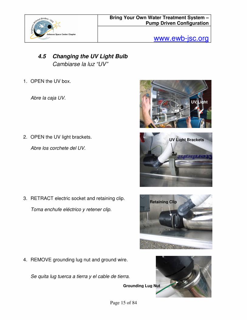
4.5 Changing the UV Light Bulb
Cambiarse la luz “UV”
1. OPEN the UV box.
Abre la caja UV. 2. OPEN the UV light brackets.
Abre los corchete del UV. 3. RETRACT electric socket and retaining clip.
Toma enchufe eléctrico y retener clip.
4. REMOVE grounding lug nut and ground wire.
Se quita lug tuerca a tierra y el cable de tierra.
UV Light
UV Light Brackets
Retaining Clip
Grounding Lug Nut
Bring Your Own Water Treatment System – Pump Driven Configuration
www.ewb-jsc.org
Page 16 of 84
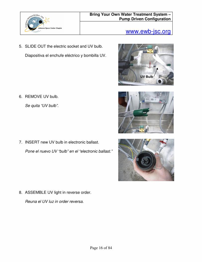
5. SLIDE OUT the electric socket and UV bulb.
Diapositiva el enchufe eléctrico y bombilla UV. 6. REMOVE UV bulb.
Se quita “UV bulb”. 7. INSERT new UV bulb in electronic ballast.
Pone el nuevo UV “bulb” en el “electronic ballast.” 8. ASSEMBLE UV light in reverse order.
Reuna el UV luz in order reversa.
UV Bulb
Bring Your Own Water Treatment System – Pump Driven Configuration
www.ewb-jsc.org
Page 17 of 84
5.0 Build Procedures
5.1 Plastic Drum Sand Filter
Step Number
Instructions Rationale
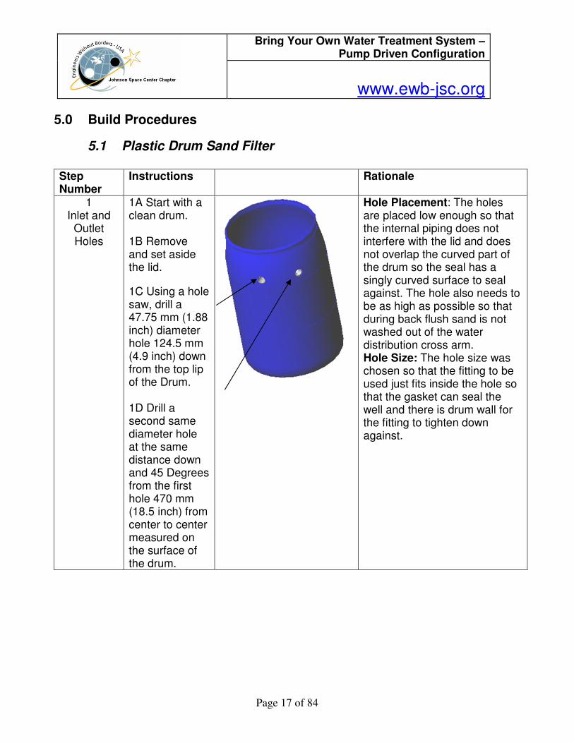
1 Inlet and
Outlet Holes
1A Start with a clean drum. 1B Remove and set aside the lid.
1C Using a hole saw, drill a 47.75 mm (1.88 inch) diameter hole 124.5 mm (4.9 inch) down from the top lip of the Drum. 1D Drill a second same diameter hole at the same distance down and 45 Degrees from the first hole 470 mm (18.5 inch) from center to center measured on the surface of the drum.
Hole Placement: The holes are placed low enough so that the internal piping does not interfere with the lid and does not overlap the curved part of the drum so the seal has a singly curved surface to seal against. The hole also needs to be as high as possible so that during back flush sand is not washed out of the water distribution cross arm. Hole Size: The hole size was chosen so that the fitting to be used just fits inside the hole so that the gasket can seal the well and there is drum wall for the fitting to tighten down against.

Bring Your Own Water Treatment System – Pump Driven Configuration
www.ewb-jsc.org
Page 18 of 84
2 Placing the
First Bulkhead
Fitting
2A Using the bulkhead installation procedure, place a bulkhead fitting into one of the drilled holes.
3 Placing the
Second Bulkhead
Fitting
3 A Using the bulkhead installation procedure, place a bulkhead fitting into the second drilled holes
4 Placing the Outlet ELL
Fitting
4A Thread a MPT to slip transition fitting into the outlet bulkhead fitting. 4B Cut a 50 mm (2 inch) length of 38 mm (1.5 inch) pipe and place it into the slip fitting of the transition

Bring Your Own Water Treatment System – Pump Driven Configuration
www.ewb-jsc.org
Page 19 of 84
fitting. DO NOT glue the piece in place at this time. 4B Place a 90 degree ELL fitting over the short length of pipe with the outlet pointed down. DO NOT glue the piece in place at this time
5
Placing the Outlet Union Fitting
5A Cut a 50 mm (2 inch) length of 38 mm (1.5 inch) pipe and place it into the slip fitting of the ELL as shown. 5B Dry fit a completely assembled Union onto the connector pipe at the bottom of the ELL. Place the fitting so that the side WITHOUT the “O” ring is fitted to the ELL.

Bring Your Own Water Treatment System – Pump Driven Configuration
www.ewb-jsc.org
Page 20 of 84
6 Building the Collection Cross Arm
Sub-assembly
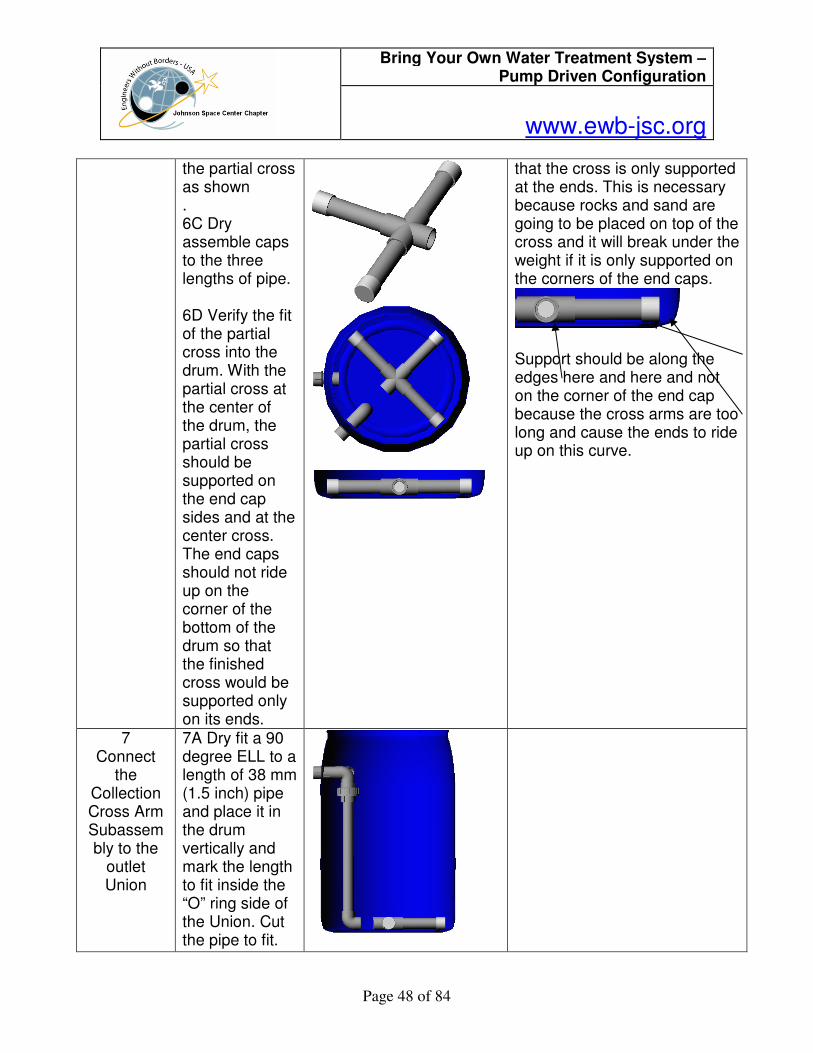
6A Start with a 38 mm cross (1.5 inch) 6B Cut three lengths of 38 mm PVC pipe to a length of 216 mm (8.5 inch) and dry assemble them (with out glue at this time) into the partial cross as shown . 6C Dry assemble caps to the three lengths of pipe. 6D Verify the fit of the partial cross into the drum. With the partial cross at the center of the drum. The partial cross should be supported on the end cap sides and at the center cross..The partial cross should sit flush on the bottom of the drum.
The collection cross arm length should be as long as possible to provide for the best distribution of flow. This length depends on the diameter of the drum that is used. The cross arm should not be so long that the ends ride up on the curved edge of the drum so that the cross is only supported at the ends. This is necessary because rocks and sand are going to be placed on top of the cross and it will break under the weight if it is only supported on the corners of the end caps.
Support should be along the edges here and here and not on the corner of the end cap because the cross arms are too long and cause the ends to ride up on this curve.
Bring Your Own Water Treatment System – Pump Driven Configuration
www.ewb-jsc.org
Page 21 of 84
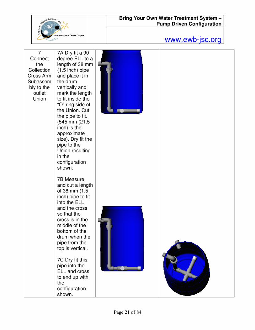
7 Connect
the Collection Cross Arm Subassembly to the
outlet Union
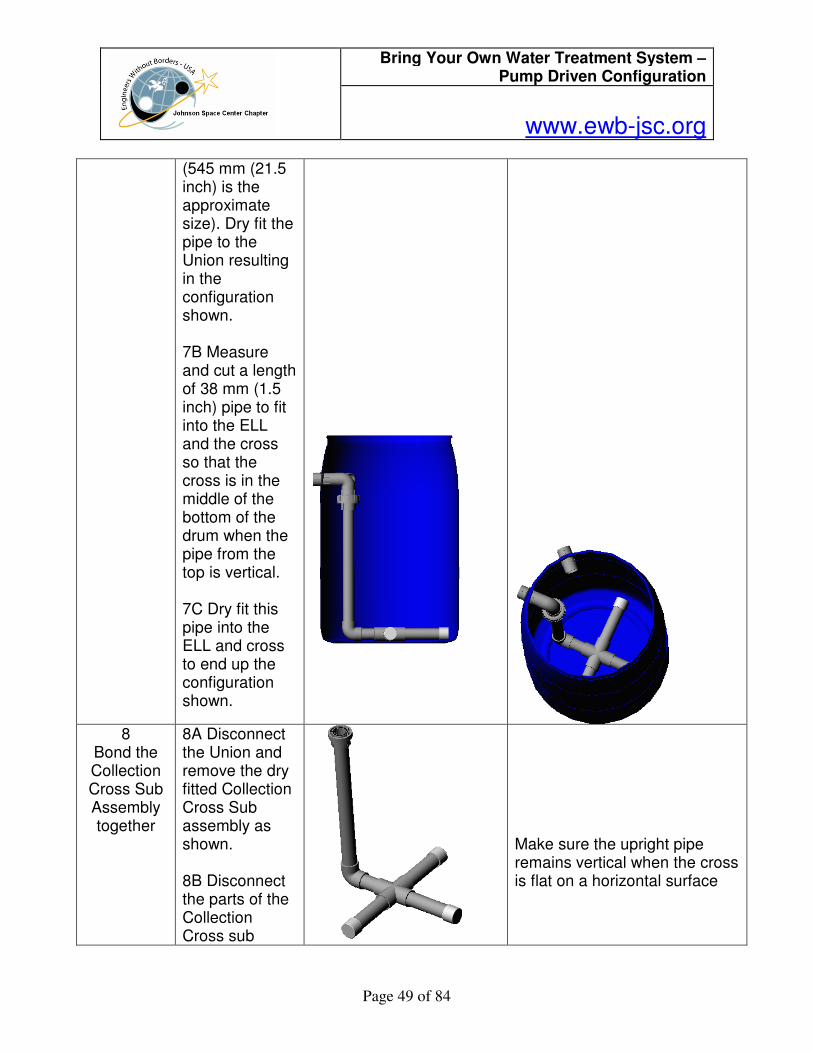
7A Dry fit a 90 degree ELL to a length of 38 mm (1.5 inch) pipe and place it in the drum vertically and mark the length to fit inside the “O” ring side of the Union. Cut the pipe to fit. (545 mm (21.5 inch) is the approximate size). Dry fit the pipe to the Union resulting in the configuration shown. 7B Measure and cut a length of 38 mm (1.5 inch) pipe to fit into the ELL and the cross so that the cross is in the middle of the bottom of the drum when the pipe from the top is vertical. 7C Dry fit this pipe into the ELL and cross to end up with the configuration shown.
Bring Your Own Water Treatment System – Pump Driven Configuration
www.ewb-jsc.org
Page 22 of 84
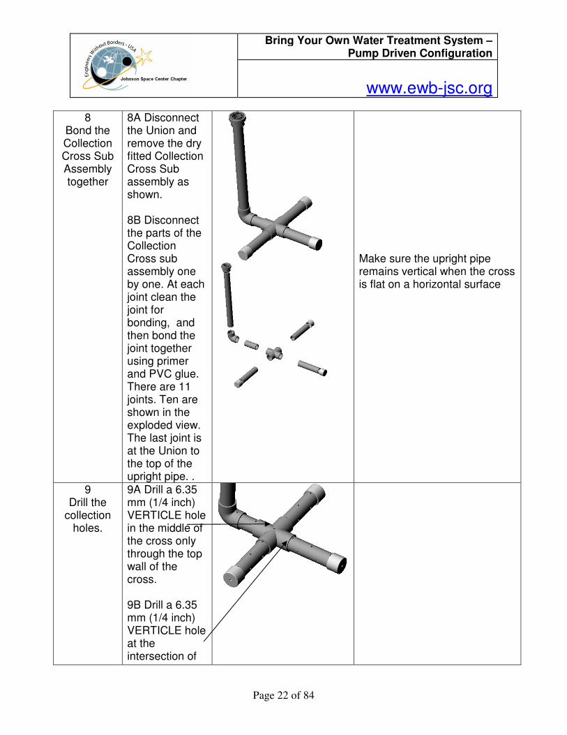
8 Bond the Collection Cross Sub Assembly together
8A Disconnect the Union and remove the dry fitted Collection Cross Sub assembly as shown. 8B Disconnect the parts of the Collection Cross sub assembly one by one. At each joint clean the joint for bonding, and then bond the joint together using primer and PVC glue. There are 11 joints. Ten are shown in the exploded view. The last joint is at the Union to the top of the upright pipe. .
Make sure the upright pipe remains vertical when the cross is flat on a horizontal surface
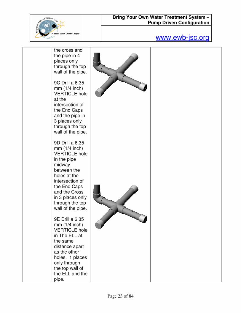
9 Drill the
collection holes.
9A Drill a 6.35 mm (1/4 inch) VERTICLE hole in the middle of the cross only through the top wall of the cross. 9B Drill a 6.35 mm (1/4 inch) VERTICLE hole at the intersection of
Bring Your Own Water Treatment System – Pump Driven Configuration
www.ewb-jsc.org
Page 23 of 84
the cross and the pipe in 4 places only through the top wall of the pipe. 9C Drill a 6.35 mm (1/4 inch) VERTICLE hole at the intersection of the End Caps and the pipe in 3 places only through the top wall of the pipe. 9D Drill a 6.35 mm (1/4 inch) VERTICLE hole in the pipe midway between the holes at the intersection of the End Caps and the Cross in 3 places only through the top wall of the pipe. 9E Drill a 6.35 mm (1/4 inch) VERTICLE hole in The ELL at the same distance apart as the other holes. 1 places only through the top wall of the ELL and the pipe.
Bring Your Own Water Treatment System – Pump Driven Configuration
www.ewb-jsc.org
Page 24 of 84
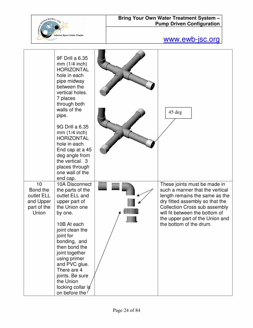
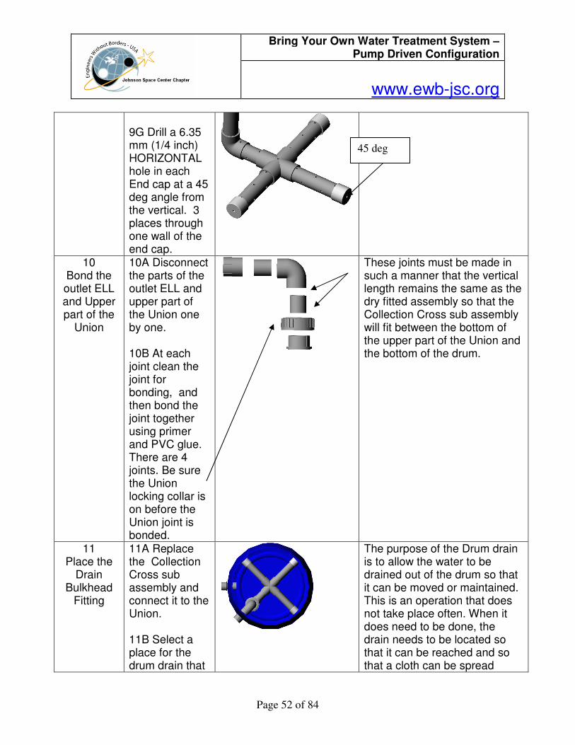
9F Drill a 6.35 mm (1/4 inch) HORIZONTAL hole in each pipe midway between the vertical holes. 7 places through both walls of the pipe. 9G Drill a 6.35 mm (1/4 inch) HORIZONTAL hole in each End cap at a 45 deg angle from the vertical. 3 places through one wall of the end cap.
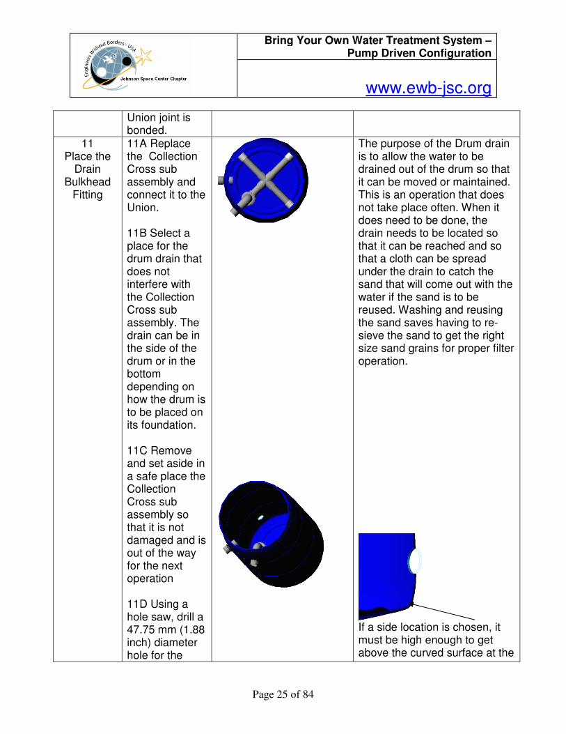
10 Bond the outlet ELL and Upper part of the
Union
10A Disconnect the parts of the outlet ELL and upper part of the Union one by one. 10B At each joint clean the joint for bonding, and then bond the joint together using primer and PVC glue. There are 4 joints. Be sure the Union locking collar is on before the
These joints must be made in such a manner that the vertical length remains the same as the dry fitted assembly so that the Collection Cross sub assembly will fit between the bottom of the upper part of the Union and the bottom of the drum.
45 deg
Bring Your Own Water Treatment System – Pump Driven Configuration
www.ewb-jsc.org
Page 25 of 84
Union joint is bonded.
11 Place the
Drain Bulkhead
Fitting
11A Replace the Collection Cross sub assembly and connect it to the Union. 11B Select a place for the drum drain that does not interfere with the Collection Cross sub assembly. The drain can be in the side of the drum or in the bottom depending on how the drum is to be placed on its foundation. 11C Remove and set aside in a safe place the Collection Cross sub assembly so that it is not damaged and is out of the way for the next operation 11D Using a hole saw, drill a 47.75 mm (1.88 inch) diameter hole for the
The purpose of the Drum drain is to allow the water to be drained out of the drum so that it can be moved or maintained. This is an operation that does not take place often. When it does need to be done, the drain needs to be located so that it can be reached and so that a cloth can be spread under the drain to catch the sand that will come out with the water if the sand is to be reused. Washing and reusing the sand saves having to re-sieve the sand to get the right size sand grains for proper filter operation.
If a side location is chosen, it must be high enough to get above the curved surface at the
Bring Your Own Water Treatment System – Pump Driven Configuration
www.ewb-jsc.org
Page 26 of 84
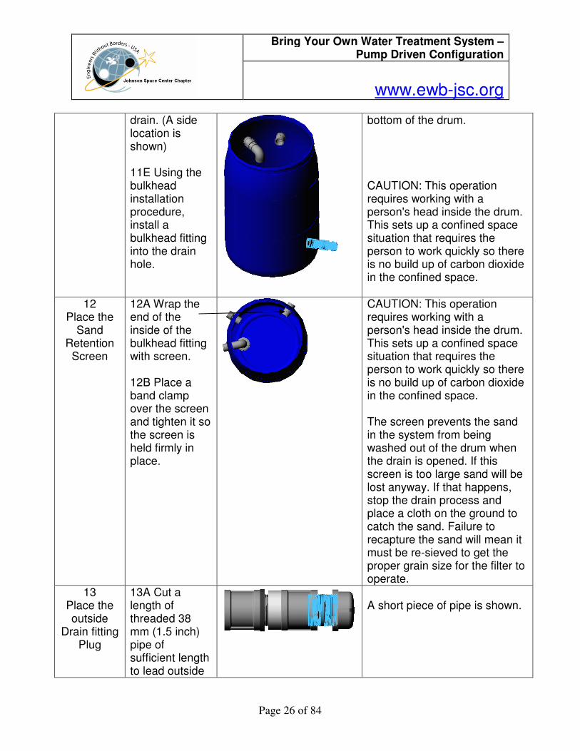
drain. (A side location is shown) 11E Using the bulkhead installation procedure, install a bulkhead fitting into the drain hole.
bottom of the drum. CAUTION: This operation requires working with a person's head inside the drum. This sets up a confined space situation that requires the person to work quickly so there is no build up of carbon dioxide in the confined space.
12 Place the
Sand Retention
Screen
12A Wrap the end of the inside of the bulkhead fitting with screen. 12B Place a band clamp over the screen and tighten it so the screen is held firmly in place.
CAUTION: This operation requires working with a person's head inside the drum. This sets up a confined space situation that requires the person to work quickly so there is no build up of carbon dioxide in the confined space. The screen prevents the sand in the system from being washed out of the drum when the drain is opened. If this screen is too large sand will be lost anyway. If that happens, stop the drain process and place a cloth on the ground to catch the sand. Failure to recapture the sand will mean it must be re-sieved to get the proper grain size for the filter to operate.
13 Place the outside
Drain fitting Plug
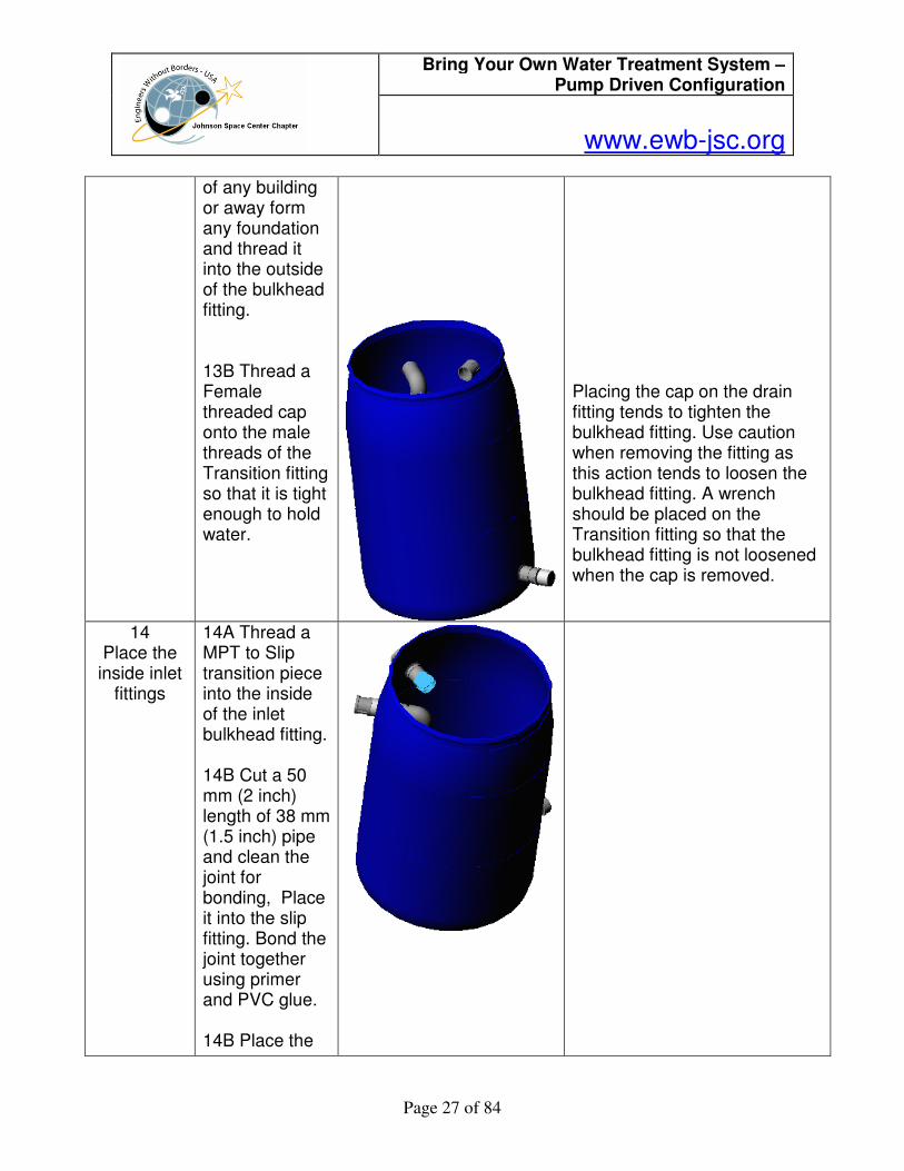
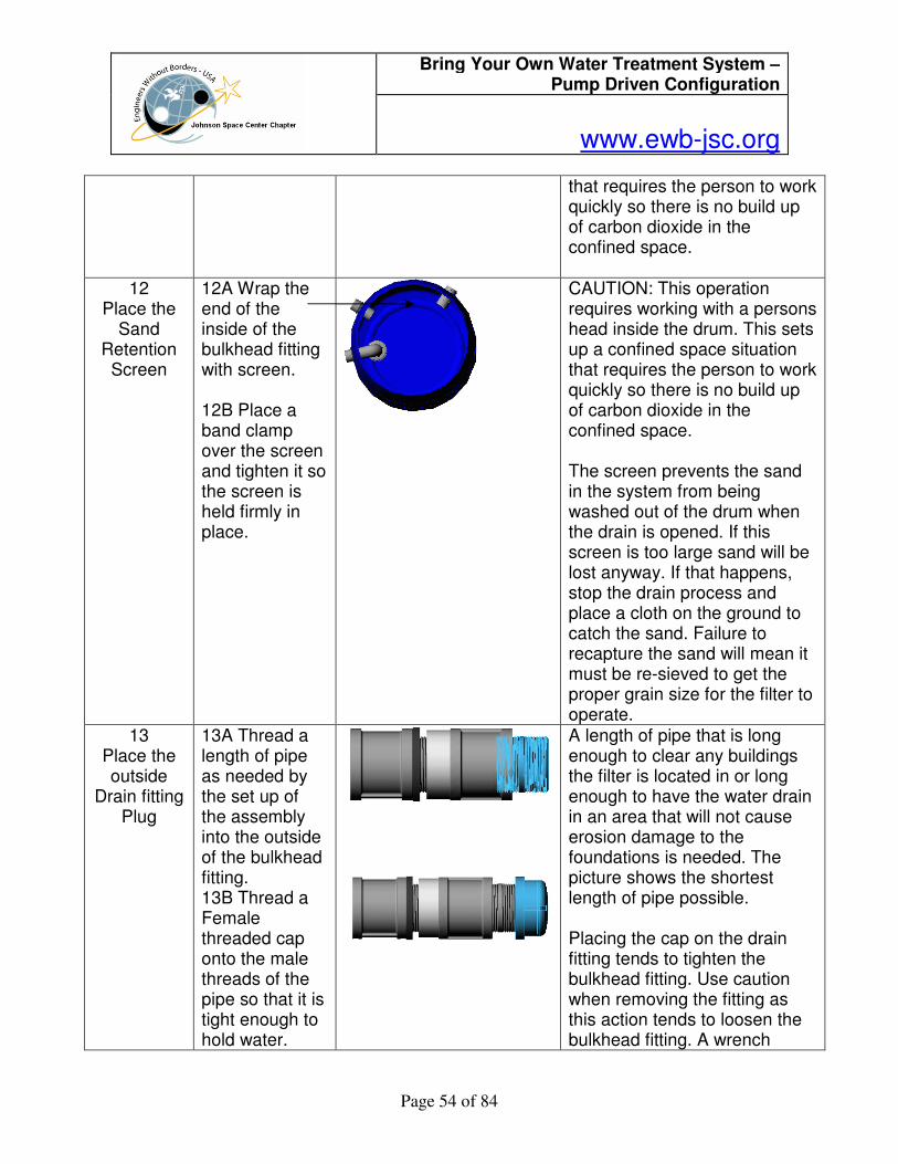
13A Cut a length of threaded 38 mm (1.5 inch) pipe of sufficient length to lead outside
A short piece of pipe is shown.
Bring Your Own Water Treatment System – Pump Driven Configuration
www.ewb-jsc.org
Page 27 of 84
of any building or away form any foundation and thread it into the outside of the bulkhead fitting. 13B Thread a Female threaded cap onto the male threads of the Transition fitting so that it is tight enough to hold water.
Placing the cap on the drain fitting tends to tighten the bulkhead fitting. Use caution when removing the fitting as this action tends to loosen the bulkhead fitting. A wrench should be placed on the Transition fitting so that the bulkhead fitting is not loosened when the cap is removed.
14 Place the
inside inlet fittings
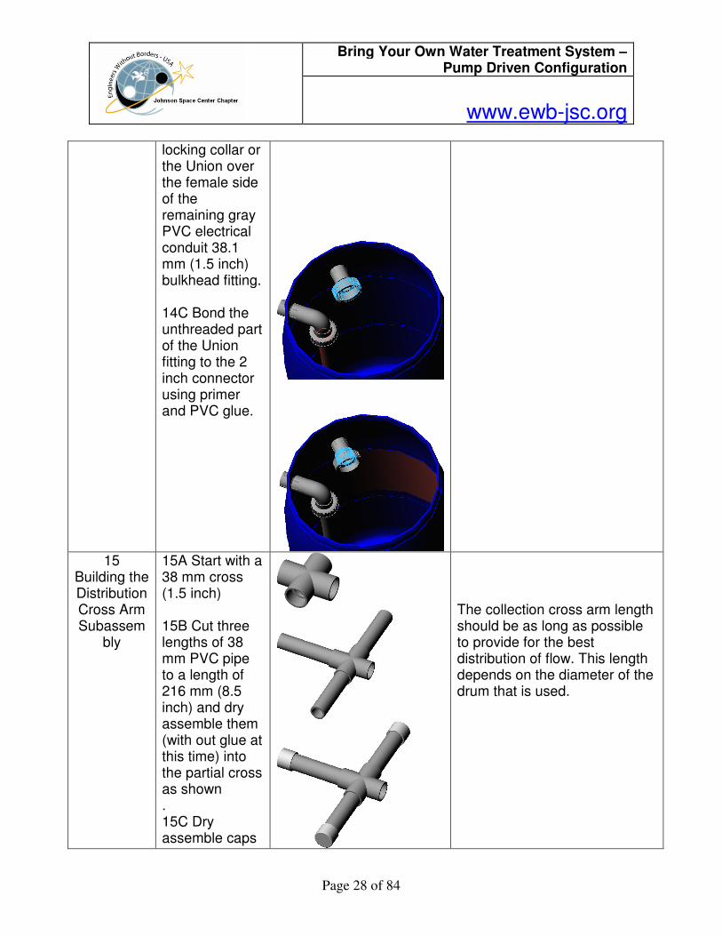
14A Thread a MPT to Slip transition piece into the inside of the inlet bulkhead fitting. 14B Cut a 50 mm (2 inch) length of 38 mm (1.5 inch) pipe and clean the joint for bonding, Place it into the slip fitting. Bond the joint together using primer and PVC glue. 14B Place the
Bring Your Own Water Treatment System – Pump Driven Configuration
www.ewb-jsc.org
Page 28 of 84
locking collar or the Union over the female side of the remaining gray PVC electrical conduit 38.1 mm (1.5 inch) bulkhead fitting. 14C Bond the unthreaded part of the Union fitting to the 2 inch connector using primer and PVC glue.
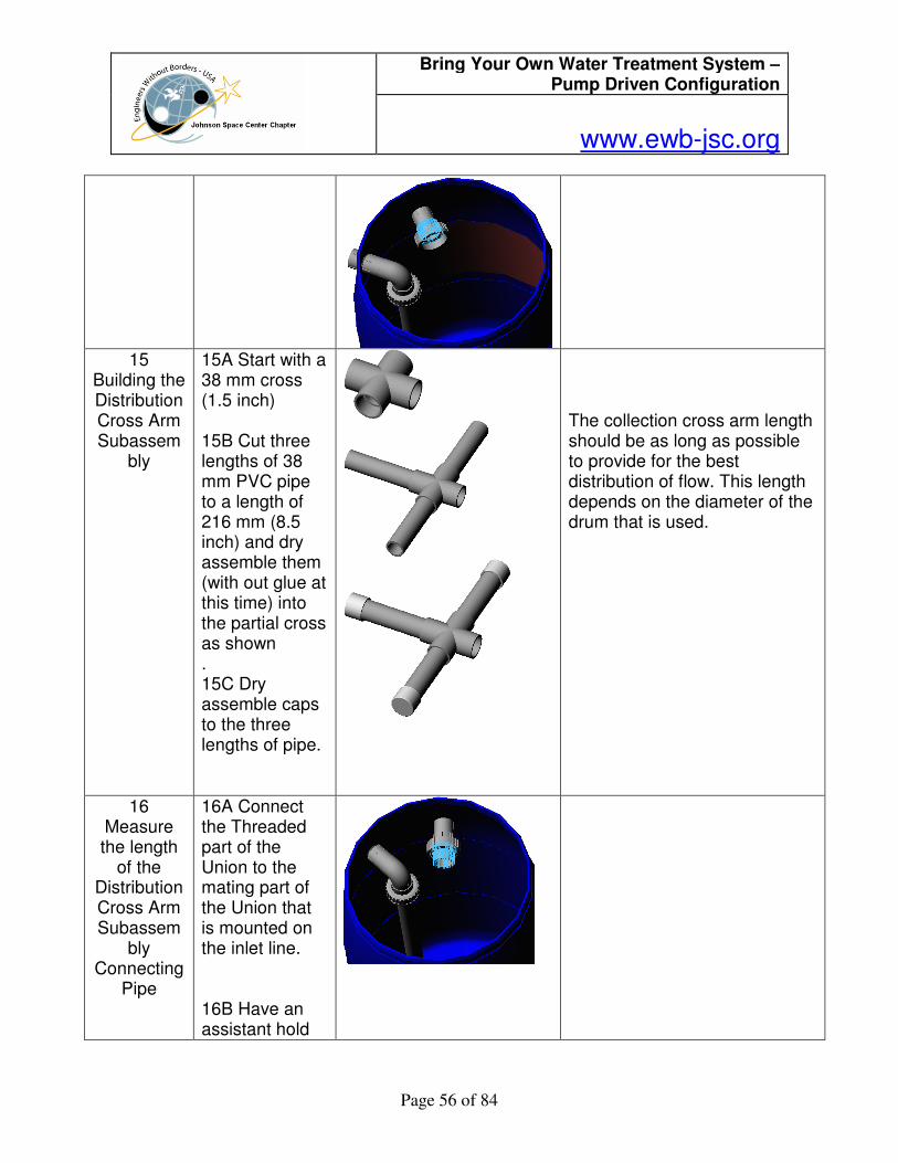
15
Building the Distribution Cross Arm Subassem
bly
15A Start with a 38 mm cross (1.5 inch) 15B Cut three lengths of 38 mm PVC pipe to a length of 216 mm (8.5 inch) and dry assemble them (with out glue at this time) into the partial cross as shown . 15C Dry assemble caps
The collection cross arm length should be as long as possible to provide for the best distribution of flow. This length depends on the diameter of the drum that is used.
Bring Your Own Water Treatment System – Pump Driven Configuration
www.ewb-jsc.org
Page 29 of 84
to the three lengths of pipe.
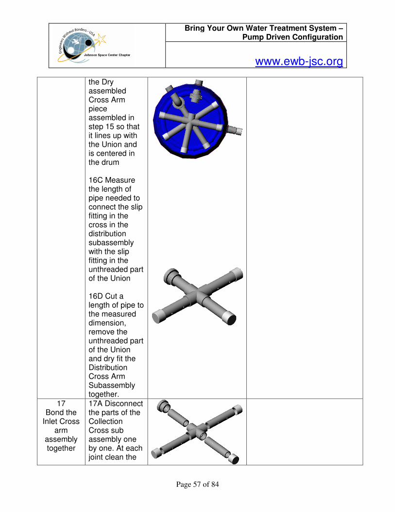
16 Measure the length
of the Distribution Cross Arm Subassem
bly Connecting
Pipe
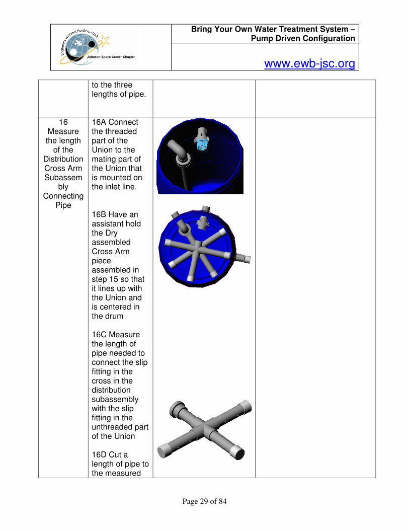
16A Connect the threaded part of the Union to the mating part of the Union that is mounted on the inlet line. 16B Have an assistant hold the Dry assembled Cross Arm piece assembled in step 15 so that it lines up with the Union and is centered in the drum 16C Measure the length of pipe needed to connect the slip fitting in the cross in the distribution subassembly with the slip fitting in the unthreaded part of the Union 16D Cut a length of pipe to the measured

Bring Your Own Water Treatment System – Pump Driven Configuration
www.ewb-jsc.org
Page 30 of 84
dimension, remove the unthreaded part of the Union and dry fit the Distribution Cross Arm Subassembly together.
17 17A Disconnect the parts of the Collection Cross sub assembly one by one. At each joint clean the joint for bonding, and then bond the joint together using primer and PVC glue. There are 8 joints.
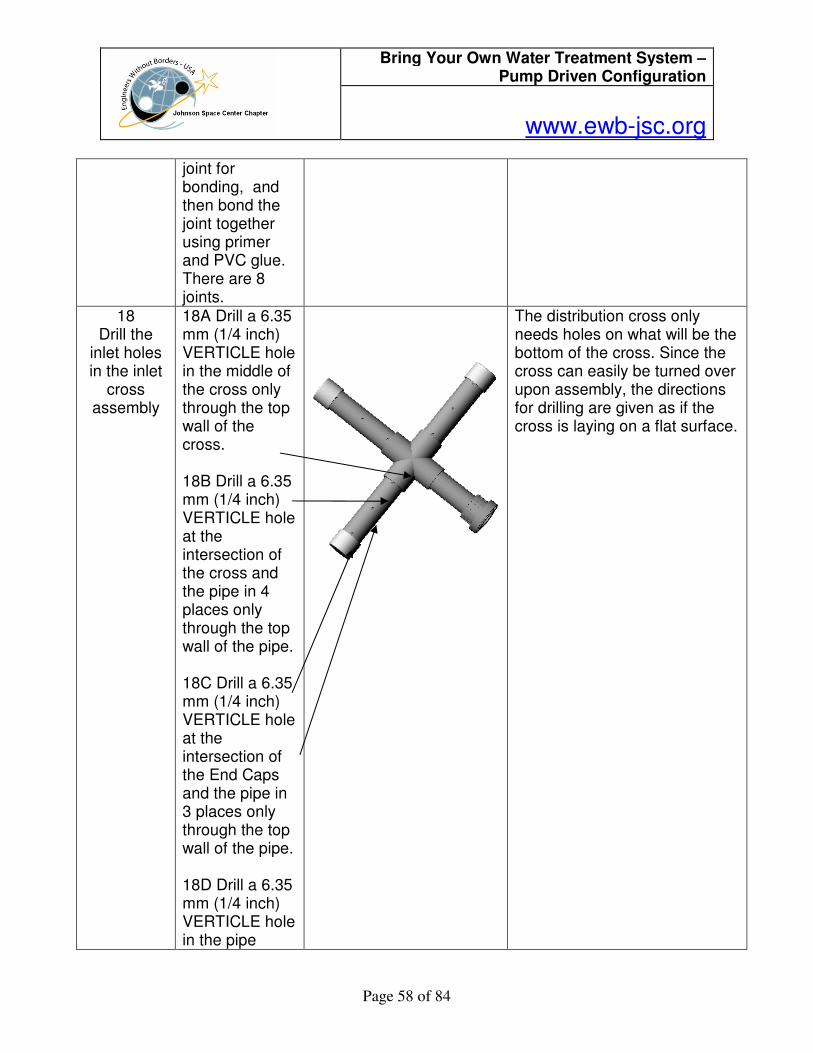
18
Drill the inlet holes
18A Drill a 6.35 mm (1/4 inch) VERTICAL hole in the middle of
The distribution cross only needs holes on what will be the bottom of the cross. Since the cross can easily be turned over
Bring Your Own Water Treatment System – Pump Driven Configuration
www.ewb-jsc.org
Page 31 of 84
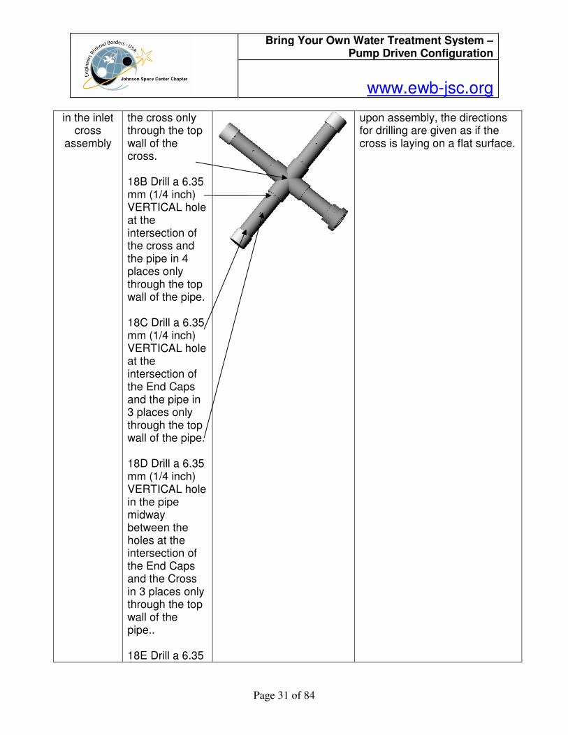
in the inlet cross
assembly
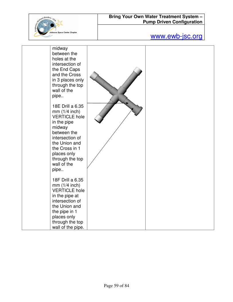
the cross only through the top wall of the cross. 18B Drill a 6.35 mm (1/4 inch) VERTICAL hole at the intersection of the cross and the pipe in 4 places only through the top wall of the pipe. 18C Drill a 6.35 mm (1/4 inch) VERTICAL hole at the intersection of the End Caps and the pipe in 3 places only through the top wall of the pipe. 18D Drill a 6.35 mm (1/4 inch) VERTICAL hole in the pipe midway between the holes at the intersection of the End Caps and the Cross in 3 places only through the top wall of the pipe.. 18E Drill a 6.35
upon assembly, the directions for drilling are given as if the cross is laying on a flat surface.
Bring Your Own Water Treatment System – Pump Driven Configuration
www.ewb-jsc.org
Page 32 of 84
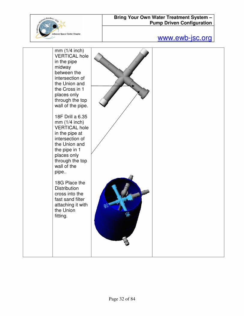
mm (1/4 inch) VERTICAL hole in the pipe midway between the intersection of the Union and the Cross in 1 places only through the top wall of the pipe. 18F Drill a 6.35 mm (1/4 inch) VERTICAL hole in the pipe at intersection of the Union and the pipe in 1 places only through the top wall of the pipe.. 18G Place the Distribution cross into the fast sand filter attaching it with the Union fitting.
Bring Your Own Water Treatment System – Pump Driven Configuration
www.ewb-jsc.org
Page 33 of 84
19 Build the
Inlet Valve Sub-
assembly
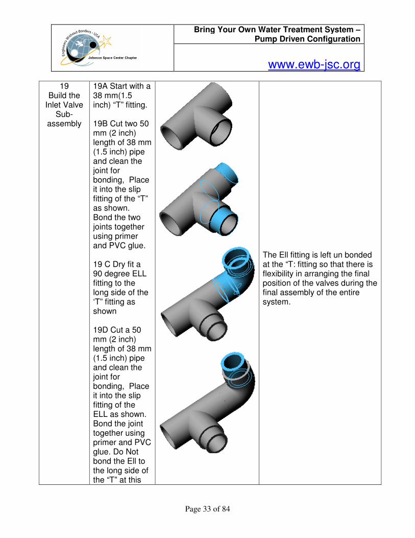
19A Start with a 38 mm(1.5 inch) “T” fitting. 19B Cut two 50 mm (2 inch) length of 38 mm (1.5 inch) pipe and clean the joint for bonding, Place it into the slip fitting of the “T” as shown. Bond the two joints together using primer and PVC glue. 19 C Dry fit a 90 degree ELL fitting to the long side of the ‘T” fitting as shown 19D Cut a 50 mm (2 inch) length of 38 mm (1.5 inch) pipe and clean the joint for bonding, Place it into the slip fitting of the ELL as shown. Bond the joint together using primer and PVC glue. Do Not bond the Ell to the long side of the “T” at this
The Ell fitting is left un bonded at the “T: fitting so that there is flexibility in arranging the final position of the valves during the final assembly of the entire system.
Bring Your Own Water Treatment System – Pump Driven Configuration
www.ewb-jsc.org
Page 34 of 84
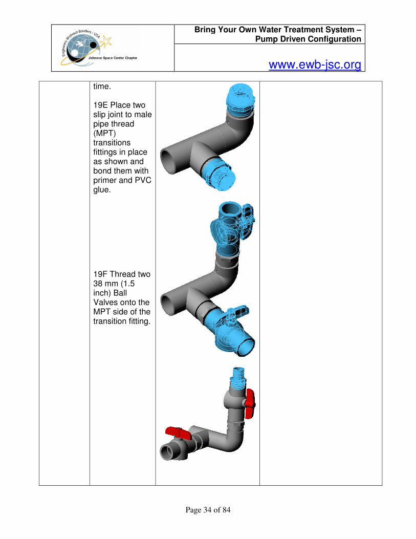
time. 19E Place two slip joint to male pipe thread (MPT) transitions fittings in place as shown and bond them with primer and PVC glue. 19F Thread two 38 mm (1.5 inch) Ball Valves onto the MPT side of the transition fitting.
Bring Your Own Water Treatment System – Pump Driven Configuration
www.ewb-jsc.org
Page 35 of 84
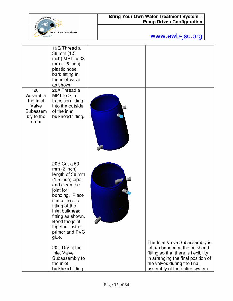
19G Thread a 38 mm (1.5 inch) MPT to 38 mm (1.5 inch) plastic hose barb fitting in the inlet valve as shown
20 Assemble the Inlet Valve
Subassembly to the
drum
20A Thread a MPT to Slip transition fitting into the outside of the inlet bulkhead fitting. 20B Cut a 50 mm (2 inch) length of 38 mm (1.5 inch) pipe and clean the joint for bonding, Place it into the slip fitting of the inlet bulkhead fitting as shown. Bond the joint together using primer and PVC glue. 20C Dry fit the Inlet Valve Subassembly to the inlet bulkhead fitting.
The Inlet Valve Subassembly is left un bonded at the bulkhead fitting so that there is flexibility in arranging the final position of the valves during the final assembly of the entire system
Bring Your Own Water Treatment System – Pump Driven Configuration
www.ewb-jsc.org
Page 36 of 84
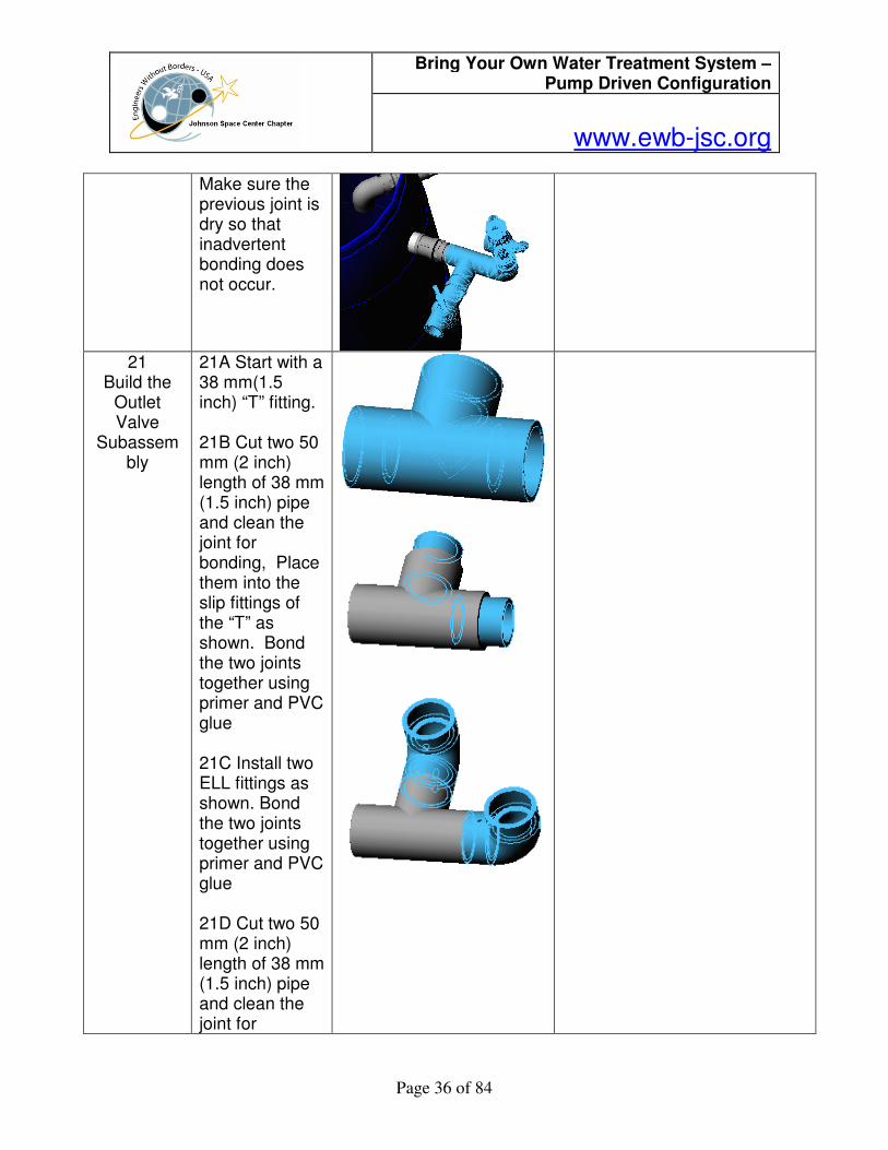
Make sure the previous joint is dry so that inadvertent bonding does not occur.
21
Build the Outlet Valve
Subassembly
21A Start with a 38 mm(1.5 inch) “T” fitting. 21B Cut two 50 mm (2 inch) length of 38 mm (1.5 inch) pipe and clean the joint for bonding, Place them into the slip fittings of the “T” as shown. Bond the two joints together using primer and PVC glue 21C Install two ELL fittings as shown. Bond the two joints together using primer and PVC glue 21D Cut two 50 mm (2 inch) length of 38 mm (1.5 inch) pipe and clean the joint for

Bring Your Own Water Treatment System – Pump Driven Configuration
www.ewb-jsc.org
Page 37 of 84
bonding, Place them into the slip fittings of the two ELL fittings as shown. Bond the two joints together using primer and PVC glue 21E Install two slip fitting to 38 mm (1.5 inch) male pipe thread (MPT) transition fittings at the ELL fittings as shown. Bond the joint together using primer and PVC glue
Bring Your Own Water Treatment System – Pump Driven Configuration
www.ewb-jsc.org
Page 38 of 84
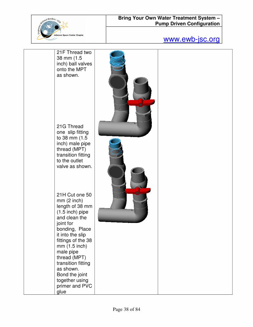
21F Thread two 38 mm (1.5 inch) ball valves onto the MPT as shown. 21G Thread one slip fitting to 38 mm (1.5 inch) male pipe thread (MPT) transition fitting to the outlet valve as shown. 21H Cut one 50 mm (2 inch) length of 38 mm (1.5 inch) pipe and clean the joint for bonding, Place it into the slip fittings of the 38 mm (1.5 inch) male pipe thread (MPT) transition fitting as shown. Bond the joint together using primer and PVC glue
Bring Your Own Water Treatment System – Pump Driven Configuration
www.ewb-jsc.org
Page 39 of 84
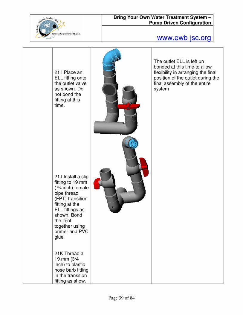
21 I Place an ELL fitting onto the outlet valve as shown. Do not bond the fitting at this time. 21J Install a slip fitting to 19 mm ( ¾ inch) female pipe thread (FPT) transition fitting at the ELL fittings as shown. Bond the joint together using primer and PVC glue 21K Thread a 19 mm (3/4 inch) to plastic hose barb fitting in the transition fitting as show.
The outlet ELL is left un bonded at this time to allow flexibility in arranging the final position of the outlet during the final assembly of the entire system
Bring Your Own Water Treatment System – Pump Driven Configuration
www.ewb-jsc.org
Page 40 of 84
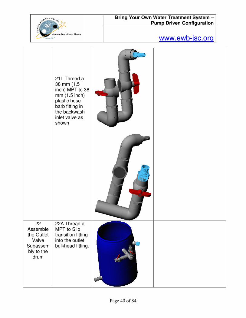
21L Thread a 38 mm (1.5 inch) MPT to 38 mm (1.5 inch) plastic hose barb fitting in the backwash inlet valve as shown
22
Assemble the Outlet
Valve Subassembly to the
drum
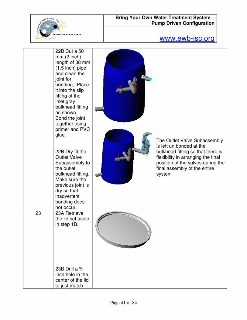
22A Thread a MPT to Slip transition fitting into the outlet bulkhead fitting.
Bring Your Own Water Treatment System – Pump Driven Configuration
www.ewb-jsc.org
Page 41 of 84
22B Cut a 50 mm (2 inch) length of 38 mm (1.5 inch) pipe and clean the joint for bonding, Place it into the slip fitting of the inlet gray bulkhead fitting as shown. Bond the joint together using primer and PVC glue. 22B Dry fit the Outlet Valve Subassembly to the outlet bulkhead fitting. Make sure the previous joint is dry so that inadvertent bonding does not occur.
The Outlet Valve Subassembly is left un bonded at the bulkhead fitting so that there is flexibility in arranging the final position of the valves during the final assembly of the entire system
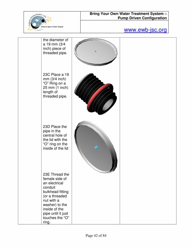
23 23A Retrieve the lid set aside in step 1B. 23B Drill a ¾ inch hole in the center of the lid to just match
Bring Your Own Water Treatment System – Pump Driven Configuration
www.ewb-jsc.org
Page 42 of 84
the diameter of a 19 mm (3/4 inch) piece of threaded pipe. 23C Place a 19 mm (3/4 inch) “O” Ring on a 25 mm (1 inch) length of threaded pipe. 23D Place the pipe in the central hole of the lid with the “O” ring on the inside of the lid 23E Thread the female side of an electrical conduit bulkhead fitting (or a threaded nut with a washer) to the inside of the pipe until it just touches the “O” ring.
Bring Your Own Water Treatment System – Pump Driven Configuration
www.ewb-jsc.org
Page 43 of 84
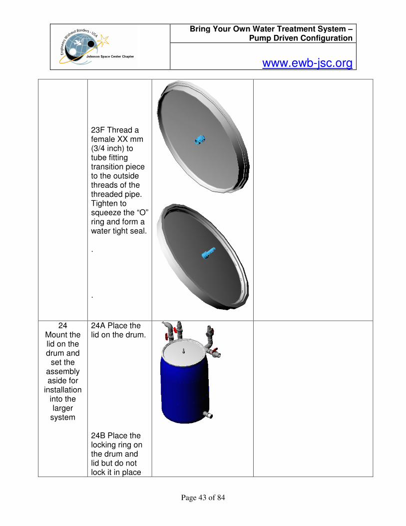
23F Thread a female XX mm (3/4 inch) to tube fitting transition piece to the outside threads of the threaded pipe. Tighten to squeeze the “O” ring and form a water tight seal. . .
24 Mount the lid on the drum and
set the assembly aside for
installation into the larger
system
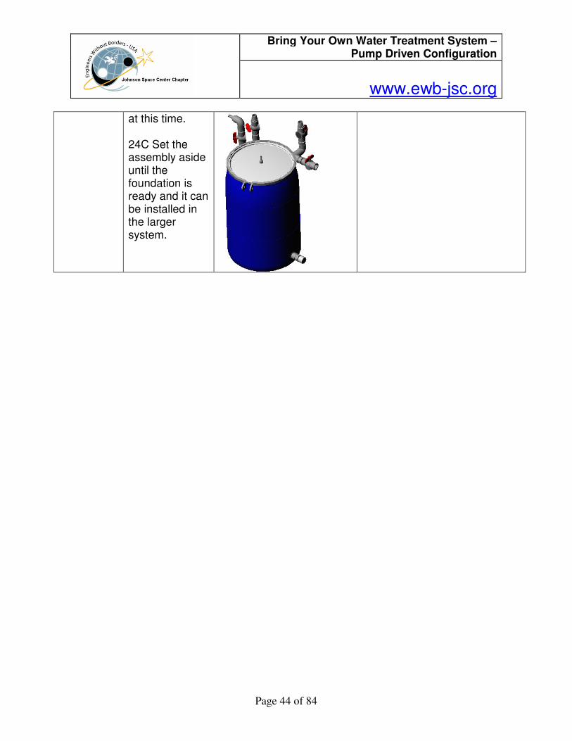
24A Place the lid on the drum. 24B Place the locking ring on the drum and lid but do not lock it in place
Bring Your Own Water Treatment System – Pump Driven Configuration
www.ewb-jsc.org
Page 44 of 84
at this time. 24C Set the assembly aside until the foundation is ready and it can be installed in the larger system.
Bring Your Own Water Treatment System – Pump Driven Configuration
www.ewb-jsc.org
Page 45 of 84
Plastic Drum Gravel Filter
Step Number
Instructions Rationale
1 Inlet and
Outlet Holes
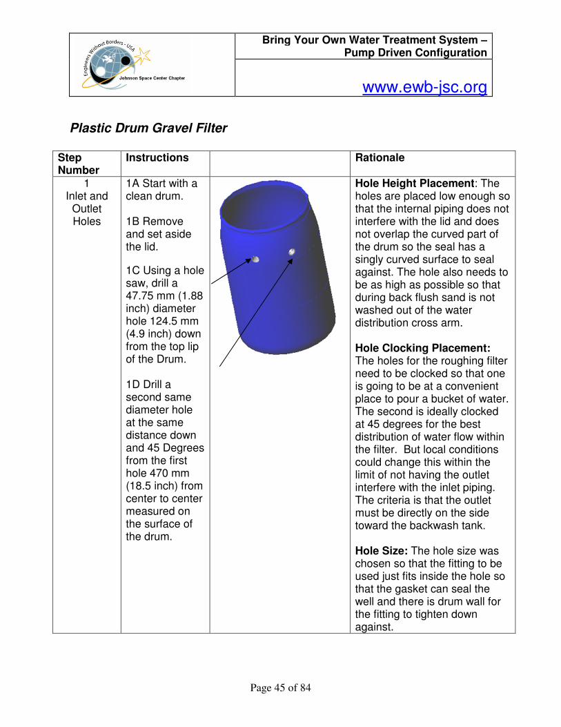
1A Start with a clean drum. 1B Remove and set aside the lid.
1C Using a hole saw, drill a 47.75 mm (1.88 inch) diameter hole 124.5 mm (4.9 inch) down from the top lip of the Drum. 1D Drill a second same diameter hole at the same distance down and 45 Degrees from the first hole 470 mm (18.5 inch) from center to center measured on the surface of the drum.
Hole Height Placement: The holes are placed low enough so that the internal piping does not interfere with the lid and does not overlap the curved part of the drum so the seal has a singly curved surface to seal against. The hole also needs to be as high as possible so that during back flush sand is not washed out of the water distribution cross arm. Hole Clocking Placement: The holes for the roughing filter need to be clocked so that one is going to be at a convenient place to pour a bucket of water. The second is ideally clocked at 45 degrees for the best distribution of water flow within the filter. But local conditions could change this within the limit of not having the outlet interfere with the inlet piping. The criteria is that the outlet must be directly on the side toward the backwash tank. Hole Size: The hole size was chosen so that the fitting to be used just fits inside the hole so that the gasket can seal the well and there is drum wall for the fitting to tighten down against.
Bring Your Own Water Treatment System – Pump Driven Configuration
www.ewb-jsc.org
Page 46 of 84
2 Placing the
First Bulkhead
Fitting
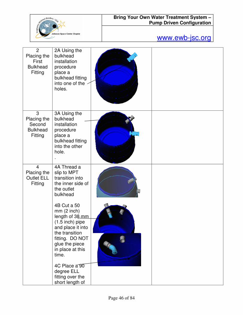
2A Using the bulkhead installation procedure place a bulkhead fitting into one of the holes.
3 Placing the
Second Bulkhead
Fitting
3A Using the bulkhead installation procedure place a bulkhead fitting into the other hole. .
4 Placing the Outlet ELL
Fitting
4A Thread a slip to MPT transition into the inner side of the outlet bulkhead 4B Cut a 50 mm (2 inch) length of 38 mm (1.5 inch) pipe and place it into the transition fitting. DO NOT glue the piece in place at this time. 4C Place a 90 degree ELL fitting over the short length of
Bring Your Own Water Treatment System – Pump Driven Configuration
www.ewb-jsc.org
Page 47 of 84
pipe with the outlet pointed down. DO NOT glue the piece in place at this time
5 Placing the
Outlet Union Fitting
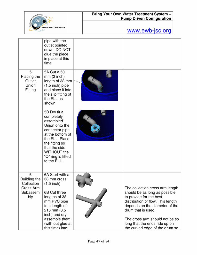
5A Cut a 50 mm (2 inch) length of 38 mm (1.5 inch) pipe and place it into the slip fitting of the ELL as shown. 5B Dry fit a completely assembled Union onto the connector pipe at the bottom of the ELL. Place the fitting so that the side WITHOUT the “O” ring is fitted to the ELL.
6 Building the Collection Cross Arm Subassem
bly
6A Start with a 38 mm cross (1.5 inch) 6B Cut three lengths of 38 mm PVC pipe to a length of 216 mm (8.5 inch) and dry assemble them (with out glue at this time) into
The collection cross arm length should be as long as possible to provide for the best distribution of flow. This length depends on the diameter of the drum that is used. The cross arm should not be so long that the ends ride up on the curved edge of the drum so
Bring Your Own Water Treatment System – Pump Driven Configuration
www.ewb-jsc.org
Page 48 of 84
the partial cross as shown . 6C Dry assemble caps to the three lengths of pipe. 6D Verify the fit of the partial cross into the drum. With the partial cross at the center of the drum, the partial cross should be supported on the end cap sides and at the center cross. The end caps should not ride up on the corner of the bottom of the drum so that the finished cross would be supported only on its ends.
that the cross is only supported at the ends. This is necessary because rocks and sand are going to be placed on top of the cross and it will break under the weight if it is only supported on the corners of the end caps.
Support should be along the edges here and here and not on the corner of the end cap because the cross arms are too long and cause the ends to ride up on this curve.
7 Connect
the Collection Cross Arm Subassembly to the
outlet Union
7A Dry fit a 90 degree ELL to a length of 38 mm (1.5 inch) pipe and place it in the drum vertically and mark the length to fit inside the “O” ring side of the Union. Cut the pipe to fit.
Bring Your Own Water Treatment System – Pump Driven Configuration
www.ewb-jsc.org
Page 49 of 84
(545 mm (21.5 inch) is the approximate size). Dry fit the pipe to the Union resulting in the configuration shown. 7B Measure and cut a length of 38 mm (1.5 inch) pipe to fit into the ELL and the cross so that the cross is in the middle of the bottom of the drum when the pipe from the top is vertical. 7C Dry fit this pipe into the ELL and cross to end up the configuration shown.
8
Bond the Collection Cross Sub Assembly together
8A Disconnect the Union and remove the dry fitted Collection Cross Sub assembly as shown. 8B Disconnect the parts of the Collection Cross sub
Make sure the upright pipe remains vertical when the cross is flat on a horizontal surface

Bring Your Own Water Treatment System – Pump Driven Configuration
www.ewb-jsc.org
Page 50 of 84
assembly one by one. At each joint clean the joint for bonding, and then bond the joint together using primer and PVC glue. There are 11 joints. Ten are shown in the exploded view. The last joint is at the Union to the top of the upright pipe. .
9 Drill the
collection holes.
9A Drill a 6.35 mm (1/4 inch) VERTICLE hole in the middle of the cross only through the top wall of the cross. 9B Drill a 6.35 mm (1/4 inch) VERTICLE hole at the intersection of the cross and the pipe in 4 places only through the top wall of the pipe. 9C Drill a 6.35 mm (1/4 inch) VERTICLE hole at the intersection of the End Caps

Bring Your Own Water Treatment System – Pump Driven Configuration
www.ewb-jsc.org
Page 51 of 84
and the pipe in 3 places only through the top wall of the pipe. 9D Drill a 6.35 mm (1/4 inch) VERTICLE hole in the pipe midway between the holes at the intersection of the End Caps and the Cross in 3 places only through the top wall of the pipe. 9E Drill a 6.35 mm (1/4 inch) VERTICLE hole in The ELL at the same distance apart as the other holes. 1 places only through the top wall of the ELL and the pipe. 9F Drill a 6.35 mm (1/4 inch) HORIZONTAL hole in each pipe midway between the vertical holes. 7 places through both walls of the pipe.
Bring Your Own Water Treatment System – Pump Driven Configuration
www.ewb-jsc.org
Page 52 of 84
9G Drill a 6.35 mm (1/4 inch) HORIZONTAL hole in each End cap at a 45 deg angle from the vertical. 3 places through one wall of the end cap.
10 Bond the outlet ELL and Upper part of the
Union
10A Disconnect the parts of the outlet ELL and upper part of the Union one by one. 10B At each joint clean the joint for bonding, and then bond the joint together using primer and PVC glue. There are 4 joints. Be sure the Union locking collar is on before the Union joint is bonded.
These joints must be made in such a manner that the vertical length remains the same as the dry fitted assembly so that the Collection Cross sub assembly will fit between the bottom of the upper part of the Union and the bottom of the drum.
11 Place the
Drain Bulkhead
Fitting
11A Replace the Collection Cross sub assembly and connect it to the Union. 11B Select a place for the drum drain that
The purpose of the Drum drain is to allow the water to be drained out of the drum so that it can be moved or maintained. This is an operation that does not take place often. When it does need to be done, the drain needs to be located so that it can be reached and so that a cloth can be spread
45 deg

Bring Your Own Water Treatment System – Pump Driven Configuration
www.ewb-jsc.org
Page 53 of 84
does not interfere with the Collection Cross sub assembly. The drain can be in the side of the drum or in the bottom depending on how the drum is to be placed on its foundation. 11C Remove and set aside in a safe place the Collection Cross sub assembly so that it is not damaged and is out of the way for the next operation 11D Using a hole saw, drill a 47.75 mm (1.88 inch) diameter hole for the drain. (A side location is shown) 11E Install a bulkhead fitting using the bulkhead fitting procedure.
under the drain to catch the sand that will come out with the water if the sand is to be reused. Washing and reusing the sand saves having to re-sieve the sand to get the right size sand grains for proper filter operation.
If a side location is chosen, it must be high enough to get above the curved surface at the bottom of the drum. CAUTION: This operation requires working with a persons head inside the drum. This sets up a confined space situation
Bring Your Own Water Treatment System – Pump Driven Configuration
www.ewb-jsc.org
Page 54 of 84
that requires the person to work quickly so there is no build up of carbon dioxide in the confined space.
12 Place the
Sand Retention
Screen
12A Wrap the end of the inside of the bulkhead fitting with screen. 12B Place a band clamp over the screen and tighten it so the screen is held firmly in place.
CAUTION: This operation requires working with a persons head inside the drum. This sets up a confined space situation that requires the person to work quickly so there is no build up of carbon dioxide in the confined space. The screen prevents the sand in the system from being washed out of the drum when the drain is opened. If this screen is too large sand will be lost anyway. If that happens, stop the drain process and place a cloth on the ground to catch the sand. Failure to recapture the sand will mean it must be re-sieved to get the proper grain size for the filter to operate.
13 Place the outside
Drain fitting Plug
13A Thread a length of pipe as needed by the set up of the assembly into the outside of the bulkhead fitting. 13B Thread a Female threaded cap onto the male threads of the pipe so that it is tight enough to hold water.
A length of pipe that is long enough to clear any buildings the filter is located in or long enough to have the water drain in an area that will not cause erosion damage to the foundations is needed. The picture shows the shortest length of pipe possible. Placing the cap on the drain fitting tends to tighten the bulkhead fitting. Use caution when removing the fitting as this action tends to loosen the bulkhead fitting. A wrench

Bring Your Own Water Treatment System – Pump Driven Configuration
www.ewb-jsc.org
Page 55 of 84
should be placed on the Transition fitting so that the bulkhead fitting is not loosened when the cap is removed.
14 Place the
inside inlet fittings
14A Insert a MPT to slip transition fitting into the inner side of the inlet bulkhead. 14A Cut a 50 mm (2 inch) length of 38 mm (1.5 inch) pipe and clean the joint for bonding, Place it into the slip fitting of the female side of the transition fitting. Bond the joint together using primer and PVC glue. 14B Place the locking color or the Union over the bulkhead fitting. 14C Bond the unthreaded part of the Union fitting to the 2 inch connector using primer and PVC glue.
Bring Your Own Water Treatment System – Pump Driven Configuration
www.ewb-jsc.org
Page 56 of 84
15
Building the Distribution Cross Arm Subassem
bly
15A Start with a 38 mm cross (1.5 inch) 15B Cut three lengths of 38 mm PVC pipe to a length of 216 mm (8.5 inch) and dry assemble them (with out glue at this time) into the partial cross as shown . 15C Dry assemble caps to the three lengths of pipe.
The collection cross arm length should be as long as possible to provide for the best distribution of flow. This length depends on the diameter of the drum that is used.
16 Measure the length
of the Distribution Cross Arm Subassem
bly Connecting
Pipe
16A Connect the Threaded part of the Union to the mating part of the Union that is mounted on the inlet line. 16B Have an assistant hold
Bring Your Own Water Treatment System – Pump Driven Configuration
www.ewb-jsc.org
Page 57 of 84
the Dry assembled Cross Arm piece assembled in step 15 so that it lines up with the Union and is centered in the drum 16C Measure the length of pipe needed to connect the slip fitting in the cross in the distribution subassembly with the slip fitting in the unthreaded part of the Union 16D Cut a length of pipe to the measured dimension, remove the unthreaded part of the Union and dry fit the Distribution Cross Arm Subassembly together.
17 Bond the
Inlet Cross arm
assembly together
17A Disconnect the parts of the Collection Cross sub assembly one by one. At each joint clean the
Bring Your Own Water Treatment System – Pump Driven Configuration
www.ewb-jsc.org
Page 58 of 84
joint for bonding, and then bond the joint together using primer and PVC glue. There are 8 joints.
18 Drill the
inlet holes in the inlet
cross assembly
18A Drill a 6.35 mm (1/4 inch) VERTICLE hole in the middle of the cross only through the top wall of the cross. 18B Drill a 6.35 mm (1/4 inch) VERTICLE hole at the intersection of the cross and the pipe in 4 places only through the top wall of the pipe. 18C Drill a 6.35 mm (1/4 inch) VERTICLE hole at the intersection of the End Caps and the pipe in 3 places only through the top wall of the pipe. 18D Drill a 6.35 mm (1/4 inch) VERTICLE hole in the pipe
The distribution cross only needs holes on what will be the bottom of the cross. Since the cross can easily be turned over upon assembly, the directions for drilling are given as if the cross is laying on a flat surface.
Bring Your Own Water Treatment System – Pump Driven Configuration
www.ewb-jsc.org
Page 59 of 84
midway between the holes at the intersection of the End Caps and the Cross in 3 places only through the top wall of the pipe.. 18E Drill a 6.35 mm (1/4 inch) VERTICLE hole in the pipe midway between the intersection of the Union and the Cross in 1 places only through the top wall of the pipe.. 18F Drill a 6.35 mm (1/4 inch) VERTICLE hole in the pipe at intersection of the Union and the pipe in 1 places only through the top wall of the pipe.
Bring Your Own Water Treatment System – Pump Driven Configuration
www.ewb-jsc.org
Page 60 of 84
Bulkhead Build
Step Number
Instructions Rationale
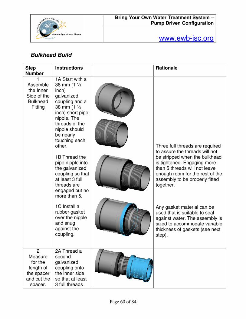
1 Assemble the Inner
Side of the Bulkhead
Fitting
1A Start with a 38 mm (1 ½ inch) galvanized coupling and a 38 mm (1 ½ inch) short pipe nipple. The threads of the nipple should be nearly touching each other. 1B Thread the pipe nipple into the galvanized coupling so that at least 3 full threads are engaged but no more than 5.
1C Install a rubber gasket over the nipple and snug against the coupling.
Three full threads are required to assure the threads will not be stripped when the bulkhead is tightened. Engaging more than 5 threads will not leave enough room for the rest of the assembly to be properly fitted together. Any gasket material can be used that is suitable to seal against water. The assembly is sized to accommodate variable thickness of gaskets (see next step).
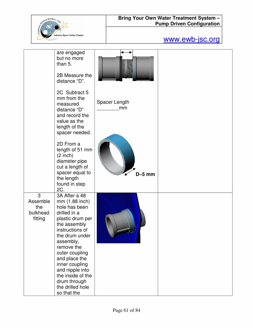
2 Measure for the
length of the spacer and cut the
spacer.
2A Thread a second galvanized coupling onto the inner side so that at least 3 full threads
Bring Your Own Water Treatment System – Pump Driven Configuration
www.ewb-jsc.org
Page 61 of 84
are engaged but no more than 5. 2B Measure the distance “D”. 2C Subtract 5 mm from the measured distance “D” and record the value as the length of the spacer needed. 2D From a length of 51 mm (2 inch) diameter pipe cut a length of spacer equal to the length found in step 2C.
Spacer Length ________mm
D–5 mm
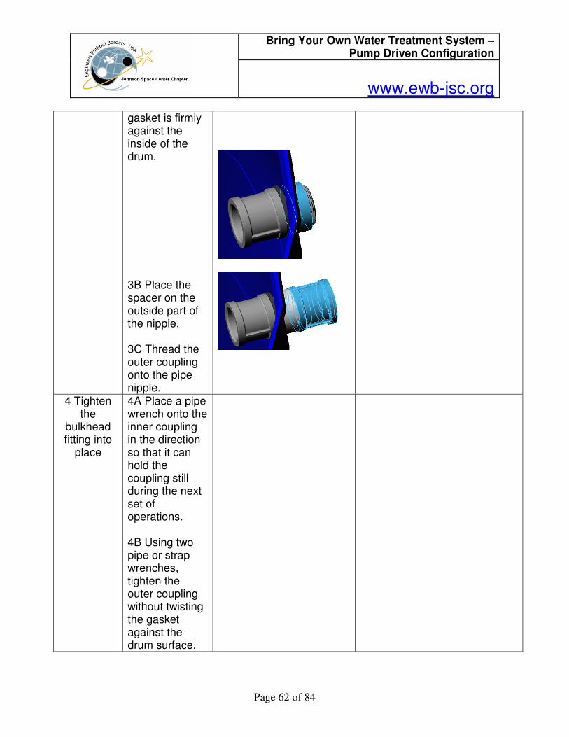
3 Assemble
the bulkhead
fitting
3A After a 48 mm (1.88 inch) hole has been drilled in a plastic drum per the assembly instructions of the drum under assembly, remove the outer coupling and place the inner coupling and nipple into the inside of the drum through the drilled hole so that the
Bring Your Own Water Treatment System – Pump Driven Configuration
www.ewb-jsc.org
Page 62 of 84
gasket is firmly against the inside of the drum. 3B Place the spacer on the outside part of the nipple. 3C Thread the outer coupling onto the pipe nipple.
4 Tighten the
bulkhead fitting into
place
4A Place a pipe wrench onto the inner coupling in the direction so that it can hold the coupling still during the next set of operations. 4B Using two pipe or strap wrenches, tighten the outer coupling without twisting the gasket against the drum surface.

Bring Your Own Water Treatment System – Pump Driven Configuration
www.ewb-jsc.org
Page 63 of 84
6.0 Assessment and Monitoring Plan
6.1 Water Quality Monitoring
The goal of the Water Quality Monitoring Plan is to ensure that the BYOW system is working properly and providing safe drinking water. The two main water quality parameters to be monitored are turbidity and bacterial counts in both the source water and the product water. In addition, intermediate samples collected downstream of the sand filter and upstream of the UV light will be collected intermittently. The key goal of the BYOW is the removal of pathogenic microorganisms from the source water by filtration and ultraviolet disinfection. Although some turbidity is expected in the source water, the product water must be clear and without cloudiness. The UV disinfection step requires low turbidity, as suspended particles, such as clay, can shield bacteria from the UV light. Turbidity is monitored with a turbiditimeter and bacterial monitoring is conducted with plates. 3M Petrifilm E. coli count plates are used for the enumeration of Escherichia coli and coliforms. E. coli are an intestinal organisms that indicates the water was contaminated by fecal matter. Coliform are easy to culture and their presence is used to indicate that other pathogenic organisms of fecal origin may be present. Coliform may also come from non intestinal sources such as soil and vegetation. Unlike the general coliform group, E. coli are almost exclusively of fecal origin and their presence is thus an effective confirmation of fecal contamination. Typically, E. coli are about 10% of the coliforms in human feces. The method is based on sample collection, inoculation of the plate with the liquid sample, incubation, and counting of colonies. A summary of each step is provided here. See the Hach Turbidity meter and 3M Petrafilm brochures for more details. Sample Collection Turbidty measurements require 15 mL of liquid sample and each bacterial plate measurement requires 1 mL of water, which is applied directly to the plate. The sample to be measured should be collected in a clean container that has been flushed three times with product water (effluent from the BYOW system). Frequency of Sample Collection The BYOW system should be visually inspected weekly. Samples should be collected at least monthly for turbidity and bacterial counts. More frequent sampling should be conducted when there is an observable change in the product water, such as visible cloudiness, color, or odors.
Bring Your Own Water Treatment System – Pump Driven Configuration
www.ewb-jsc.org
Page 64 of 84
Monitoring of Turbidity The Hach 2100P Portable Turbidimeter is used to measure turbidity quantitatively from 0 to 1,000 NTU (nephelometric turbidity units). In addition to the Hach turbidimeter, which gives a digital readout of the turbidity, turbidity can be assessed qualitatively by visual inspection of the water sample in a clear bottle. However, care should be taken, as a visually clear sample may still contain bacteria. Turbidity monitoring is best suited for monitoring the effectivesness of the sand filter, which removes suspended matter before UV disinfection. 1. Collect a representative sample in a clean container. Fill a sample cell to the line (about 15 mL), taking care tohandle the sample cell bythe top. Cap the cell. 2. Wipe the cell witha soft, lint-free cloth to remove water spots and fingerprints. 3. Apply a thin film of silicone oil. Wipe with a soft cloth to obtain an even film over the entire surface. 4. Press: I/O. The instrument will turn on. Place the instrument on a flat, sturdy surface. Do not hold the instrument while making measurements. 5. Insert the sample cell in the instrument cell compartment so the diamond or orientation mark aligns with the raised orientation mark in front of the cell compartment. Close the lid. 6. Select manual or automatic range selection by pressing the RANGE key. The display will show AUTO RNG when the instrument is in automatic range selection. 7. Select signal averaging mode by pressing the SIGNAL AVERAGE key. The display will show SIG AVG when the instrument is using signal averaging. Use signal average mode if the sample causes a noisy signal (display changes constantly). 8. Press: READ The display will show - - - - NTU, then the turbidity in NTU. Record the turbidity after the lamp symbol turns off. Note: The instrument defaults to the last operating mode selected. If automatic range mode and signal averaging were used on the previous measurements, these options will automatically be selected for subsequent samples. Measurement Notes Always cap the sample cell to prevent spillage of sample into the instrument. When taking a reading, place the instrument on a level, stationary surface. It should not be held in the hand during measurement. Always close the sample compartment lid during measurement and storage. Always use clean sample cells in good condition. Dirty, scratched, or damaged cells can cause inaccurate readings. Do not leave a sample cell in the cell compartment for extended periods of time. This may compress the spring in the cell holder. Remove sample cell and batteries from instrument if the instrument is stored for extended time period (more than a month). Avoid operating in direct sunlight.
Bring Your Own Water Treatment System – Pump Driven Configuration
www.ewb-jsc.org
Page 65 of 84
Make certain cold samples do not “fog” the sample cell. Avoid settling of sample prior to measurement. Keep sample compartment lid closed to prevent dust and dirt from entering. Measurement Techniques Proper measurement techniques are important in minimizing the effects of instrument variation, stray light and air bubbles. Regardless of the instrument used, measurements are more accurate, precise and repeatable if the analyst pays close attention to proper measurement techniques. Measure samples immediately to prevent temperature changes and settling. Avoid sample dilution when possible. Particles suspended in the original sample may dissolve or otherwise change characteristics when the sample temperature changes or when the sample is diluted, resulting in a non-representative sample measurement. Cleaning Sample Cells Cells must be extremely clean and free from significant scratches. The glass used to make cells is easily scratched – manufacturing cells free of minor scratches and other imperfections is difficult. However, minor imperfections are effectively masked by applying silicone oil. Clean the inside and outside of the cells by washing with BYOW product water. Follow with multiple rinses of distilled or deionized water. Allow cells to air dry. Handle cells only by the top to minimize dirt, scratches and fingerprints in the light path. Monitoring of Bacteria, Description: The 3M Petrifim E. coli Count Plate is a sample-ready medium system for enumerating Escherichia coli and other coliforms. Petrifilm E. coli Count plates contain violet red bile nutrients, a cold water soluble gelling agent, a glucuronidase indicator to identify E. coli, and a tetrazolium indicator to enhance the visualization of other gram coliform negative (non-E. coli) bacteria. Coliforms ferment the lactose in the medium to produce gas. This gas is trapped around the coliform colony and allows the differentiation of coliform bacteria from other gram negative bacteria. In addition, glucuronidate, produced by most E. coli will react with the glucuronidase indicator In the medium to produce a blue precipitate around the colony allowing visual identification of E.coli. Storage and disposal: Store unopened Petrifilm plate foil pouches at or below 80C (460F). After opening, return unused plates to foil pouches. Seal foil pouch by folding and taping the open end. Store resealed pouches at room temperature (<25C or <77F) with <50% RH. Exposure of Petrifilm plates to higher temperatures and/or humidities can affect the performance of the plates. Do

Bring Your Own Water Treatment System – Pump Driven Configuration
www.ewb-jsc.org
Page 66 of 84
not refrigerate opened packages. Use Petrifilm plates within one month after opening. Do not use plates that show orange or brown discoloration. After use, Petrifilm E. coil Count plates will contain viable bacteria. Follow current Industry standards for disposal. Directions for use: 1. Place the Petrifilm E. coil Count plate on a flat surface (see figure A). 2. Lift top film and dispense 1 ml of sample onto the center of the bottom film (see figure B). 3. Slowly roll the top film down onto the sample to prevent the entrapment of air bubbles (see figure C). 4. Distribute sample evenly within the circular well using a gentle downward pressure on the center of the plastic spreader (flat side down) (see figure D). Do not slide spreader across the film. Remove spreader and leave plate undisturbed for one minute to permit solidification of the gel. 5. Incubate plates in a horizontal position with the clear side up in stacks not exceeding 20
plates. Follow current industry standards for incubation temperature. Incubate plates 24 ± 2 hr. and examine for coliform and E. coli growth. Some E. coli colonies require additional time
to form the blue precipitate. Re-incubate plates an additional 24 ± 2 hr. to detect any additional E. coil growth. 6a. Petrifilm E. coil Count plates can be counted on a standard colony counter. The interpretation of E. coli colonies on Petrifilm E. coli Count plates varies by method. When considering which interpretation to follow please keep in mind that approximately 95% of E. coil produce gas. AOAC Method (991.14) Petrifilm plates incubated at 35 + 1C Blue colonies associated with entrapped gas (see figure F) are confirmed E. coli. Blue colonies without gas are not counted as E. coli. Other coliform colonies will be red and associated with gas bubbles. Colonies not associated with gas (with a distance greater than one colony diameter from gas bubble) are not counted as coliforms. The total coliform count consists of both the red and blue colonies associated with gas at 24 hours.

Bring Your Own Water Treatment System – Pump Driven Configuration
www.ewb-jsc.org
Page 67 of 84
Data Monitoring Form for Turbidity
Samples collected by _________________ on ______________
Location: __________________
Sample Location Date of Collection Turbidity, NTU Visual Observations

Bring Your Own Water Treatment System – Pump Driven Configuration
www.ewb-jsc.org
Page 68 of 84
Data Monitoring Form for E. coli and coliform using 3M Petrifilm Plates
Samples collected by _________________ on ______________
Sample Collections Location and Project: _________________________________
Incubator conditions, Storage Temperature = ___________
Time plates placed in Incubator = ___________________
Time plates removed from Incubator = ________________
Time colonies were counted = _________________
Sample Location Date of Collection Sample Dilution
= 1 for undiluted
# of E Coli
colonies (blue)
per sample
volume, mL
# of coliform
colonies (red)
per sample
volume, mL
3M Petrifilm E. Coli plates
Notes:
One Blue colony (dot) associated with gas bubble is counted as one E. Coli colony.
One Red colony (dot) associated with gas bubble is counted as one coliform colony.

Bring Your Own Water Treatment System – Pump Driven Configuration
www.ewb-jsc.org
Page 69 of 84
Usage Monitoring
An important assessment of the effectiveness of the BYOW system is the number of users of the system. The ideal water treatment system is only useful if it is used by the target population. The goal of usage monitoring is to quantify the number of water batches processed and estimate the number of end users of the BYOW treated water. In order to count the number of users, an observer will monitor uses with the following form. The monitoring program frequency should be sufficient to capture daily, weekly, and seasonal patterns of use and non-use. If possible, the observer should acquire additional information from the water carrier, such as the end-uses of the water and the number of people served by the individual water carrier.
Observed number of users of BYOW system
Date =
Time Period that obserations were made =
Observer Name =
System monitored (e.g. BYOW at Orphanage) =
Time of
Use
User Sex & Estimated
Age
Volume of
Water
Type of
Container
Other

Bring Your Own Water Treatment System – Pump Driven Configuration
www.ewb-jsc.org
Page 70 of 84
Time of
Use
User Sex & Estimated
Age
Volume of
Water
Type of
Container
Other
Bring Your Own Water Treatment System – Pump Driven Configuration
www.ewb-jsc.org
Page 71 of 84
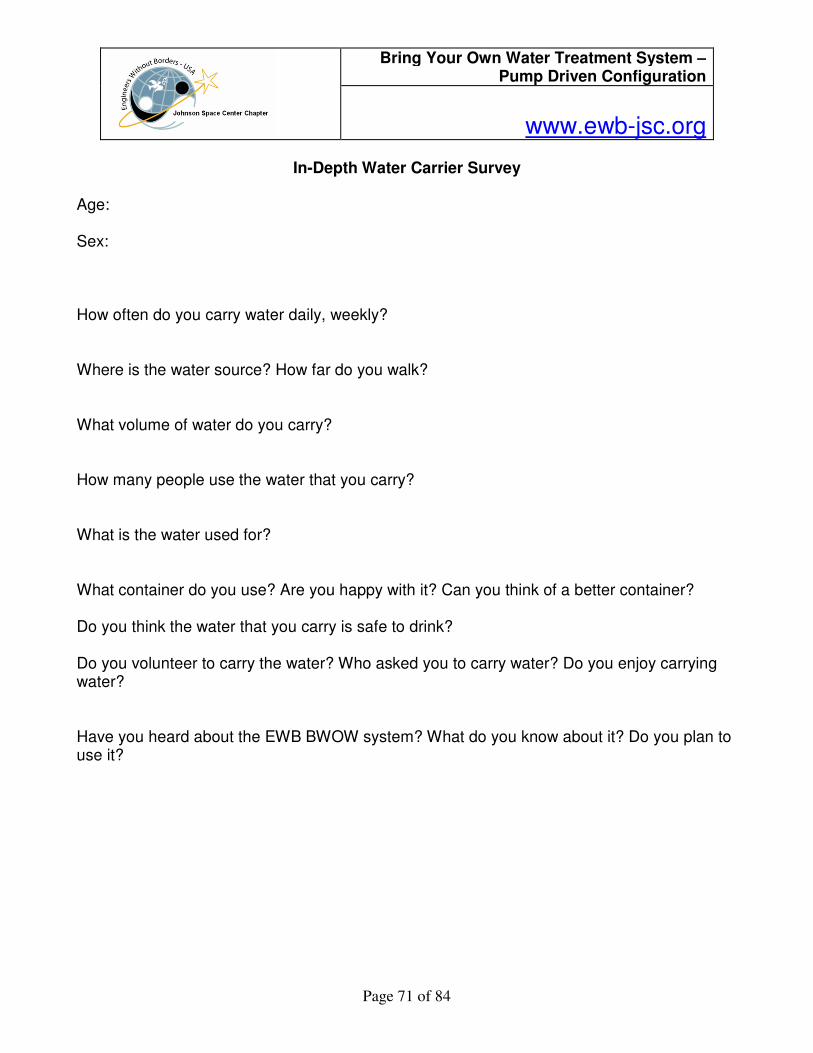
In-Depth Water Carrier Survey
Age: Sex: How often do you carry water daily, weekly? Where is the water source? How far do you walk? What volume of water do you carry? How many people use the water that you carry? What is the water used for? What container do you use? Are you happy with it? Can you think of a better container? Do you think the water that you carry is safe to drink? Do you volunteer to carry the water? Who asked you to carry water? Do you enjoy carrying water? Have you heard about the EWB BWOW system? What do you know about it? Do you plan to use it?
Bring Your Own Water Treatment System – Pump Driven Configuration
www.ewb-jsc.org
Page 72 of 84
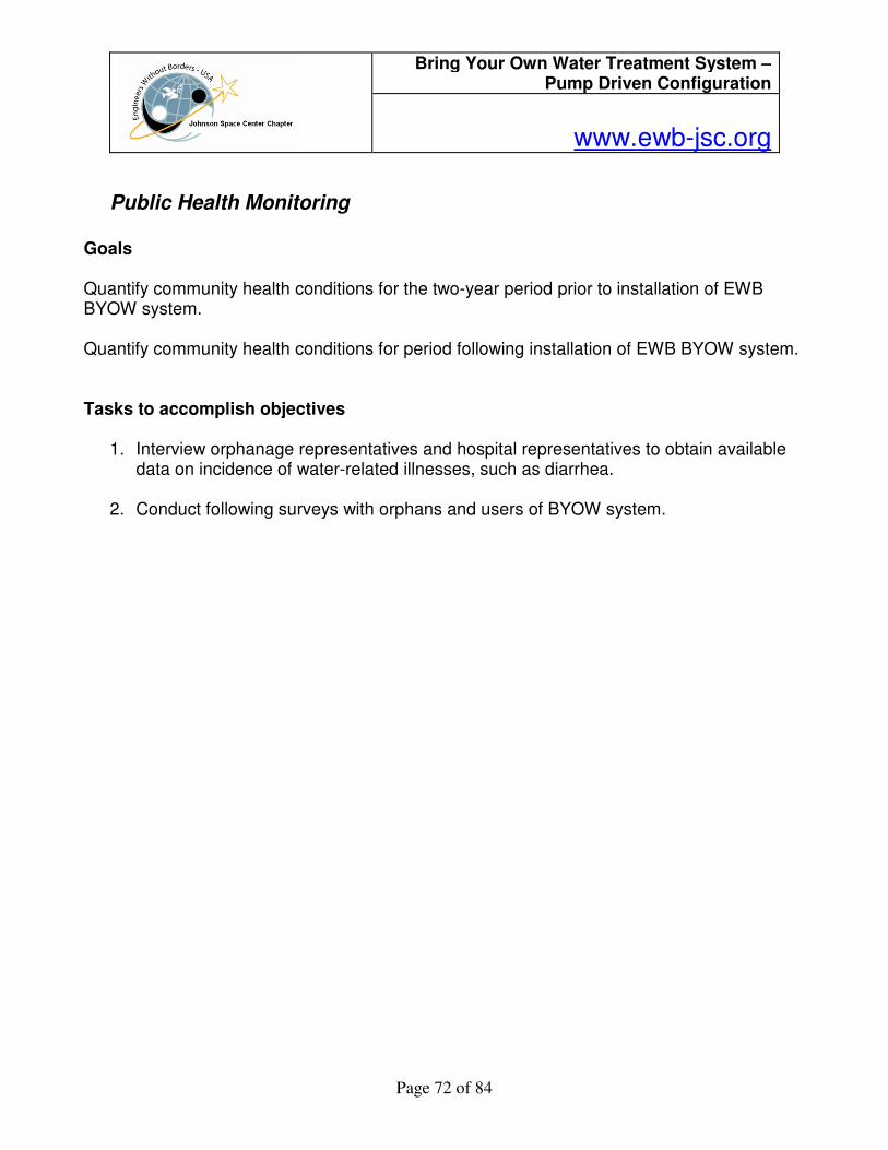
Public Health Monitoring
Goals Quantify community health conditions for the two-year period prior to installation of EWB BYOW system. Quantify community health conditions for period following installation of EWB BYOW system. Tasks to accomplish objectives
1. Interview orphanage representatives and hospital representatives to obtain available data on incidence of water-related illnesses, such as diarrhea.
2. Conduct following surveys with orphans and users of BYOW system.

Bring Your Own Water Treatment System – Pump Driven Configuration
www.ewb-jsc.org
Page 73 of 84
EWB-USA provided Public Health Assessment Forms
Instructions:
The interviewer will need to determine the geopolitical and population boundaries of the “community” the EWB project will serve and then repeatedly refer to those boundaries when conducting the interviews. You should be completing the entire attached survey with 4-8 individuals in the community (see required vs. specific project questions). There may be different ideas from different people about what is an illness and its cause so information from a cross section of the community will be more valuable. Your sources of information should include one or two individuals from each of the following groups of people. Both genders should be represented and at least 1/3 to 1/2 of the individuals should live within the community your project will serve. If there is more than one ethnic group that will benefit from your project try to include people from each group. 1) Village leaders (ask around to find out who are considered leaders, both formal and informal)
Some examples include: the village headman or elder, president of the women’s club, local government official.
2) Health care providers such as: clinic doctor or nurse, health aide, local midwife, traditional healer or Health Ministry official.
3) Educators such as: health educator, school teacher, headmaster or professor. 4) Employee of a non-governmental organization working in the area, for example: a
Peace Corps volunteer, missionary or employee of a national non-governmental agency.
5) Your own observations Ask each individual all of the required questions (indicated with **, italics and in blue) and as many of the other questions as you are able to get information about based on time and willingness to respond. Some of the ‘extra’ questions will be more appropriate for your project than others. The Health Metrics representative will assist you, if needed, in deciding which of the extra questions are important.

Bring Your Own Water Treatment System – Pump Driven Configuration
www.ewb-jsc.org
Page 74 of 84
Final Report: As part of your report turned in at the end of your project please state at least two or three ways that you plan to show how your EWB project will improve some element of the community’s quality of health or standard or living, for example, fewer cases of diarrheal illnesses in children under five, fewer deaths of women in childbirth, increased immunization rates, increased percentage of households with latrines, etc. Based on the information collected from your surveys: 1) How will you measure the impact of your project? 2) Who will measure it and how will you get the data? Section 1: Regional Demographics Section 2: Community Illness / Injury Information Section 3: Morbidity / Mortality Information Section 4: Daily living information Water, Food, Sanitation Section 6: Education / Health Education Section 7: Transportation / Communication Section 8: Goals of EWB Project
Baseline / Follow-up
EWB Community and Health Assessment Survey
Project ____________________________________________ Chapter(s) ______________________ Date of survey____________ Location (home, health clinic, community house….) _______________ Source of Information (name and role in community)________________________________________
Section One: Regional Demographics **How many people will benefit from this project? _________________________________________ For the entire community:
**Number of families: _________________________________________________________
**Number of adult men (16 years or older): ________________________________________
**Number of adult women (16 years or older): _____________________________________

Bring Your Own Water Treatment System – Pump Driven Configuration
www.ewb-jsc.org
Page 75 of 84
**Number of children ages < 1 year _________ 1-4 years _________ 5-15 years ________
**Number of elders greater than 50 years __________________________________________
**What ethnic groups or tribes live in the area that will be served by the project and the approximate size of each group __________________________________________________ ___________________________________________________________________________ ___________________________________________________________________________
What is the average age that women start to have children _____________________________
Average number of children per woman of childbearing age. ___________________________
Number of disabled persons in the community (mental and physical)_____________________

Bring Your Own Water Treatment System – Pump Driven Configuration
www.ewb-jsc.org
Page 76 of 84
Section 2: Community Illness / Injury Information **What are the 5 most important illnesses/injuries affecting people in the community? 1. Illness or injury___________________________________________________________________
Estimate the number/percentage of children ________ younger adults_________ older adults_______ w/ this problem every year.
Is this illness/injury gender specific? If so, does it affect more men or women? _____________
What do people think is the cause of this illnesses/injury or condition in the community? _____ ___________________________________________________________________________
How is it treated? By whom? Where?
_____________________________________________ 2. Illness or injury___________________________________________________________________
Estimate the number/percentage of children ________ younger adults_________ older adults_______ w/ this problem every year.
Is this illness/injury gender specific? If so, does it affect more men or women? _____________
What do people think is the cause of this illnesses/injury or condition in the community? _____ ___________________________________________________________________________ How is it treated? By whom? Where? _____________________________________________
3. Illness or injury___________________________________________________________________
Estimate the number/percentage of children ________ younger adults_________ older adults_______ w/ this problem every year.
Is this illness/injury gender specific? If so, does it affect more men or women? _____________
What do people think is the cause of this illnesses/injury or condition in the community? _____ ___________________________________________________________________________ How is it treated? By whom? Where? _____________________________________________
4. Illness or injury___________________________________________________________________
Estimate the number/percentage of children ________ younger adults_________ older adults_______ w/ this problem every year.
Is this illness/injury gender specific? If so, does it affect more men or women? _____________

Bring Your Own Water Treatment System – Pump Driven Configuration
www.ewb-jsc.org
Page 77 of 84
What do people think is the cause of this illnesses/injury or condition in the community? _____ ___________________________________________________________________________ How is it treated? By whom? Where? _____________________________________________
5. Illness or injury___________________________________________________________________
Estimate the number/percentage of children ________ younger adults_________ older adults_______ w/ this problem every year.
Is this illness/injury gender specific? If so, does it affect more men or women? _____________
What do people think is the cause of this illnesses/injury or condition in the community? _____ ___________________________________________________________________________ How is it treated? By whom? Where? _____________________________________________
**Is there a difference between the overall health of women and the health of men? _______________
**If yes, what? _______________________________________________________________ Is malaria considered a problem in the community? _________________________________________ What is done to prevent malaria? ________________________________________________________ What is done to treat malaria? __________________________________________________________ Is HIV/AIDS considered a problem in the community? _______________________________________ Is testing for HIV/AIDS available? _________ If so, where? __________________________________ Is tuberculosis (TB) considered a problem in the community? _________________________________ Where do most of those with TB go for treatment? _________________________________________ If so, where is treatment or medication available? __________________________________________

Bring Your Own Water Treatment System – Pump Driven Configuration
www.ewb-jsc.org
Page 78 of 84
Section 3: Morbidity / Mortality Information **What is the average life span of women? ____________________ men? ______________________ **Total number of births in the community each year _______________________________________ **Total number of deaths in the community each year ______________________________________ **Number of children less than 1 year old that die each year _________________________________ **Most common causes of death : #1_________________ #2_________________ #3_________________ #4_________________ #5_________________ **Are there certain diseases that always occur at specific times of the year? Explain. _____________ ___________________________________________________________________________________ Number of children from 1 to 5 years old that die each year __________________________________ Number of women who die during childbirth each year ______________________________________
Section 4: Daily living information
Water **Where do people get water (streams, springs, household taps, community taps, rainwater, wells)?
For drinking: _________________________________________________________________
For cooking: _________________________________________________________________
For bathing: _________________________________________________________________ For hand-washing:
____________________________________________________________ For animals:
_________________________________________________________________ For irrigation: ________________________________________________________________
**On average, how far do people have to travel to get to their drinking water source? _____________
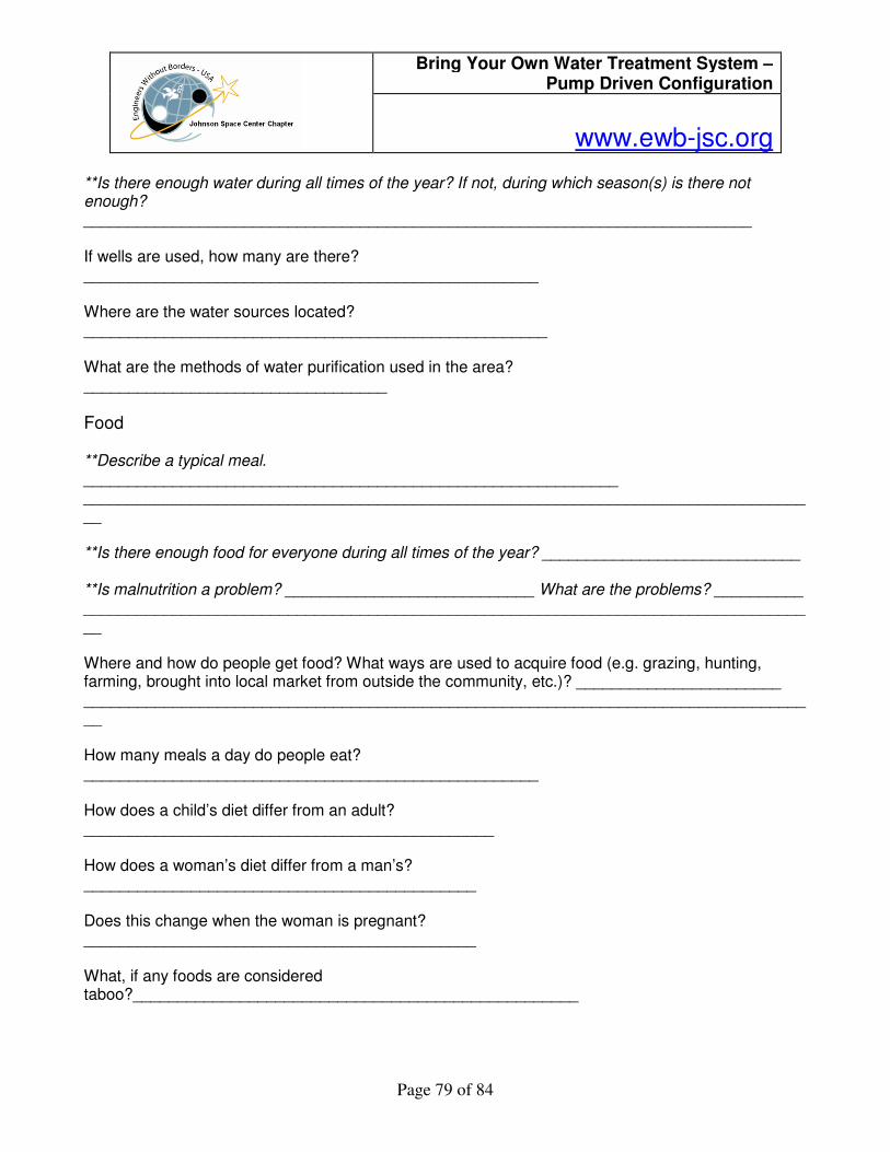
Bring Your Own Water Treatment System – Pump Driven Configuration
www.ewb-jsc.org
Page 79 of 84
**Is there enough water during all times of the year? If not, during which season(s) is there not enough? ___________________________________________________________________________ If wells are used, how many are there? ___________________________________________________ Where are the water sources located? ____________________________________________________ What are the methods of water purification used in the area? __________________________________
Food **Describe a typical meal. ____________________________________________________________ ___________________________________________________________________________________ **Is there enough food for everyone during all times of the year? _____________________________ **Is malnutrition a problem? ____________________________ What are the problems? __________ ___________________________________________________________________________________ Where and how do people get food? What ways are used to acquire food (e.g. grazing, hunting, farming, brought into local market from outside the community, etc.)? _______________________ ___________________________________________________________________________________ How many meals a day do people eat? ___________________________________________________ How does a child’s diet differ from an adult? ______________________________________________ How does a woman’s diet differ from a man’s? ____________________________________________ Does this change when the woman is pregnant? ____________________________________________ What, if any foods are considered taboo?__________________________________________________

Bring Your Own Water Treatment System – Pump Driven Configuration
www.ewb-jsc.org
Page 80 of 84
What percentage of women breastfeed their children.________________________________________
Sanitation **What do people use for bathroom facilities and what is the approximate percentage of each?
Flush toilet _______________ Indoors_________ Outdoors ______________
Pit latrines _______________ Neighboring fields_____________ Other, describe _______________
**How do people dispose of their garbage? _______________________________________________ What percentage of homes have bathroom facilities (either indoors or outdoors)? _________________ Are there community bathroom facilities? How many and where are they? ______________________ Are bathroom facilities of some sort available to all community members? ______________________ Are there community garbage dumps? If so, where are they located? __________________________ ___________________________________________________________________________________ ____________________________________________________________________________________________________________________________________________________________________________________________________________________________________________________________________________________________________________________________________________
Section 5: Community Health Resources **What is the nearest health facility? Is this an in-patient facility (people spend the night like in a U.S. hospital) or outpatient only? ___________________________________________________________ **Who staffs this facility? (physician, nurse, health aide, traditional healer) _____________________ ___________________________________________________________________________________ **Does the health facility have constant, reliable electricity (24/7)? ____________________________ **How do most people get to this facility? ________________________________________________

Bring Your Own Water Treatment System – Pump Driven Configuration
www.ewb-jsc.org
Page 81 of 84
**What types of traditional health care providers are in the community? ________________________ _____________________________How many of each type are there? _________________________ **What percentage of children in the community is immunized? ______________________________ **What are the barriers to immunization? (cost, transportation, availability, lack of electricity, cultural taboos, other…)_______________________________________________________________ **What public health programs are functioning in the community? ____________________________ ___________________________________________________________________________________ How far is it from the community? ______________________________________________________ Is transportation a barrier to obtaining medical treatment? ___________________________________ Is cost a barrier to obtaining medical treatment? ___________________________________________ Where do these traditional health care providers receive their training and what sort of training do they receive? ___________________________________________________________________________ ___________________________________________________________________________________ ___________________________________________________________________________________ Where do the children receive immunizations? _____________________________________________ What immunizations are available for children (Measles, Mumps, Rubella, tetanus, polio, pneumovax, influenza, Hepatitis A, Hepatitis B, other_________________________________________________) Who provides the vaccines/immunizations? _______________________________________________ Do parents pay for the vaccines? ________________________________________________________ Where do people get their medications? __________________________________________________ How do they pay for their medications? __________________________________________________

Bring Your Own Water Treatment System – Pump Driven Configuration
www.ewb-jsc.org
Page 82 of 84
Section 6: Education / Health Education **Is there a school(s) in the community? (how man and what types, and how many students in each)
Primary # of schools ___________________ # of students in each_______________________
Secondary # of schools ___________________ # of students in each_______________________
University / Technical college / Vocational # of schools ___________________ # of students in each_______________________
Religious # of schools ___________________ # of students in each_______________________
**What is the literacy rate in the region? Percentage of those who can read___________, write ___________, sign their name only ________ **To whom does the community turn for health information / education? (family, village nurse, traditional healers, teachers, radio, TV) __________________________________________________ __________________________________________________________________________________________________________________________________________________________________ Is there a health educator in the community? ______________________________________________ If they are not the same person, do the health educators have a good relationship with the health care providers in the community? ___________________________________________________________ __________________________________________________________________________________________________________________________________________________________________ Section 7: Transportation / Communication **Does public transportation go into the community? _______________________________________
What (bus, train, trucks….)? _____________________________________________________
**How many households have, or have regular, unlimited access to:
radio _____________________________________________________________________ television
____________________________________________________________________ a telephone (cellular or landline) ________________________________________________ access to a newspaper
_________________________________________________________ a vehicle
____________________________________________________________________

Bring Your Own Water Treatment System – Pump Driven Configuration
www.ewb-jsc.org
Page 83 of 84
Section 8: Goals of EWB Project **How do you think this project will benefit the community? _________________________________ _________________________________________________________________________________________________________________________________________________________________________________________________________________________________________________________ Based on above data: **How will you measure the impact of your project? _______________________________________ ____________________________________________________________________________________________________________________________________________________________________________________________________________________________________________________________________________________________________________________________________________ **Who will measure it and how will you get the data? _______________________________________ _________________________________________________________________________________________________________________________________________________________________________________________________________________________________________________________
Community Assessment Survey – EXAMPLE Family Name: Address: Number of children in household: Number of adults in household:
1. Have you heard why we’re here? 2. What do you think of the project?
3. What are your main concerns regarding water?
4. How do you think these problems should be solved? 5. What is your primary source of water?
6. What are the most common source of illnesses?
7. How much water do you use for drinking, washing, cooking, and other?

Bring Your Own Water Treatment System – Pump Driven Configuration
www.ewb-jsc.org
Page 84 of 84
8. Who collects the water and how? How much does it cost?
9. Where are the latrines, especially in relation to the water sources?
10. Where does waste end up?
11. What is the main source of income for your family?
12. How much would you be willing to spend per month on clean water?
13. Are you able to pay for your medical expenses?
14. Do the children attend school? How often and up to what level?