Embed Size (px)
DESCRIPTION
Cast Iron Models A’s - ZZ’s, 5’s - 320000’sAluminum Models 6B’s, 8B’s and 60000’s - 253400’s
Citation preview

5/00
Service Manual for Out of Production Engines 1919 - 1981
Model 6H Model WM Model FH
Model 300400 Model 6B
Model Z Model P
Motorwheel
Service Manual for Out of Production Engines1919 - 1981
Breaker Point & Magnavac Ignition Systems
Cast Iron Models A’s - ZZ’s, 5’s - 320000’sAluminum Models 6B’s, 8B’s and 60000’s - 253400’s
Milw
au
ke
eW
isc
on
sin
4 Cycle Air-Cooled EngineRepairman’s HandbookFor Briggs & Stratton Discount Parts Call 606-678-9623 or 606-561-4983
www.mymowerparts.com
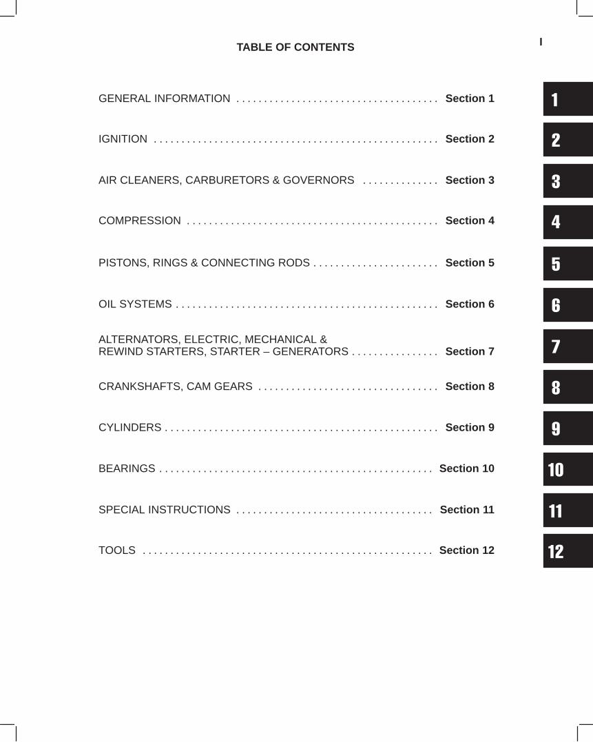
GENERAL INFORMATION Section 1. . . . . . . . . . . . . . . . . . . . . . . . . . . . . . . . . . . . .
IGNITION Section 2. . . . . . . . . . . . . . . . . . . . . . . . . . . . . . . . . . . . . . . . . . . . . . . . . . . .
AIR CLEANERS, CARBURETORS & GOVERNORS Section 3. . . . . . . . . . . . . .
COMPRESSION Section 4. . . . . . . . . . . . . . . . . . . . . . . . . . . . . . . . . . . . . . . . . . . . . .
PISTONS, RINGS & CONNECTING RODS Section 5. . . . . . . . . . . . . . . . . . . . . . .
OIL SYSTEMS Section 6. . . . . . . . . . . . . . . . . . . . . . . . . . . . . . . . . . . . . . . . . . . . . . . .
ALTERNATORS, ELECTRIC, MECHANICAL &REWIND STARTERS, STARTER – GENERATORS Section 7. . . . . . . . . . . . . . . .
CRANKSHAFTS, CAM GEARS Section 8. . . . . . . . . . . . . . . . . . . . . . . . . . . . . . . . .
CYLINDERS Section 9. . . . . . . . . . . . . . . . . . . . . . . . . . . . . . . . . . . . . . . . . . . . . . . . . .
BEARINGS Section 10. . . . . . . . . . . . . . . . . . . . . . . . . . . . . . . . . . . . . . . . . . . . . . . . . .
SPECIAL INSTRUCTIONS Section 11. . . . . . . . . . . . . . . . . . . . . . . . . . . . . . . . . . . .
TOOLS Section 12. . . . . . . . . . . . . . . . . . . . . . . . . . . . . . . . . . . . . . . . . . . . . . . . . . . . .
TABLE OF CONTENTS I
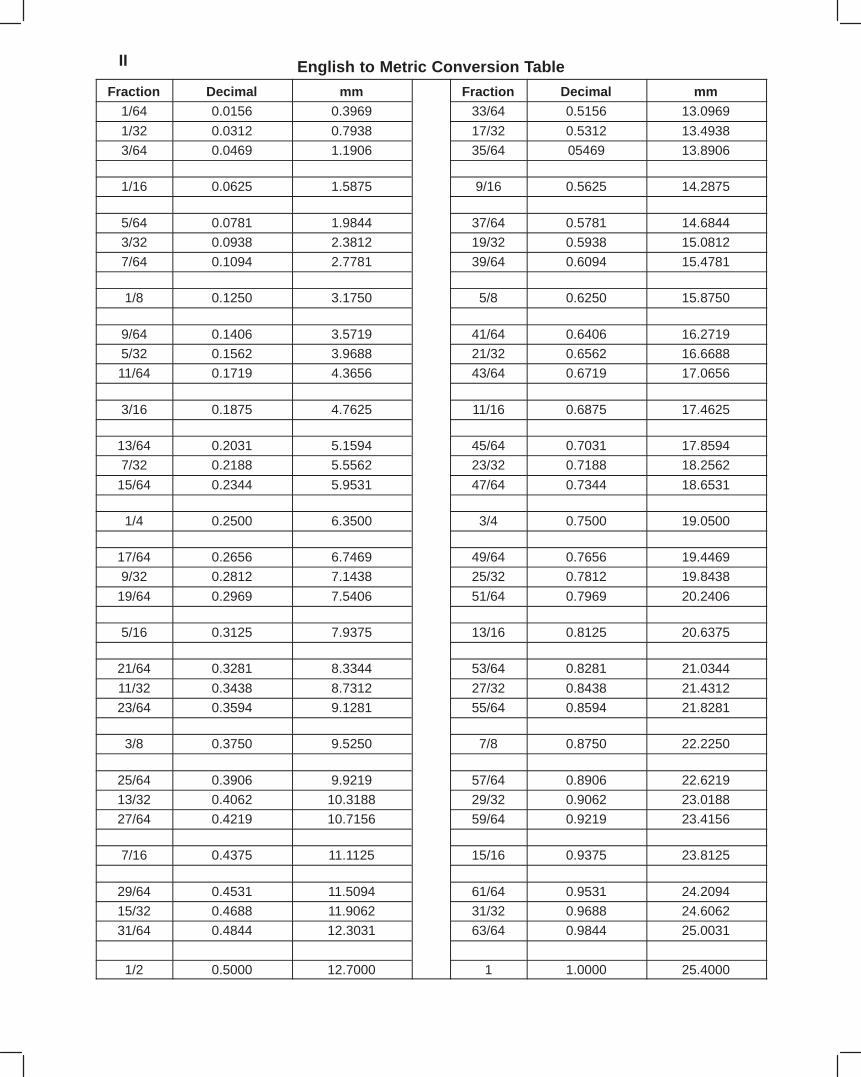
II English to Metric Conversion Table
Fraction Decimal mm Fraction Decimal mm1/64 0.0156 0.3969 33/64 0.5156 13.0969
1/32 0.0312 0.7938 17/32 0.5312 13.4938
3/64 0.0469 1.1906 35/64 05469 13.8906
1/16 0.0625 1.5875 9/16 0.5625 14.2875
5/64 0.0781 1.9844 37/64 0.5781 14.6844
3/32 0.0938 2.3812 19/32 0.5938 15.0812
7/64 0.1094 2.7781 39/64 0.6094 15.4781
1/8 0.1250 3.1750 5/8 0.6250 15.8750
9/64 0.1406 3.5719 41/64 0.6406 16.2719
5/32 0.1562 3.9688 21/32 0.6562 16.6688
11/64 0.1719 4.3656 43/64 0.6719 17.0656
3/16 0.1875 4.7625 11/16 0.6875 17.4625
13/64 0.2031 5.1594 45/64 0.7031 17.8594
7/32 0.2188 5.5562 23/32 0.7188 18.2562
15/64 0.2344 5.9531 47/64 0.7344 18.6531
1/4 0.2500 6.3500 3/4 0.7500 19.0500
17/64 0.2656 6.7469 49/64 0.7656 19.4469
9/32 0.2812 7.1438 25/32 0.7812 19.8438
19/64 0.2969 7.5406 51/64 0.7969 20.2406
5/16 0.3125 7.9375 13/16 0.8125 20.6375
21/64 0.3281 8.3344 53/64 0.8281 21.0344
11/32 0.3438 8.7312 27/32 0.8438 21.4312
23/64 0.3594 9.1281 55/64 0.8594 21.8281
3/8 0.3750 9.5250 7/8 0.8750 22.2250
25/64 0.3906 9.9219 57/64 0.8906 22.6219
13/32 0.4062 10.3188 29/32 0.9062 23.0188
27/64 0.4219 10.7156 59/64 0.9219 23.4156
7/16 0.4375 11.1125 15/16 0.9375 23.8125
29/64 0.4531 11.5094 61/64 0.9531 24.2094
15/32 0.4688 11.9062 31/32 0.9688 24.6062
31/64 0.4844 12.3031 63/64 0.9844 25.0031
1/2 0.5000 12.7000 1 1.0000 25.4000

IIIDrill Size – Decimal Equivalent In Inches
60 .040
59 .041
58 .042
57 .043
56 .0465
55 .052
54 .055
53 .0595
1/16 .0625
52 .0635
51 .067
50 .070
49 .073
48 .076
5/64 .0781
47 .0785
46 .081
45 .082
44 .086
43 .089
42 .0935
3/32 .0938
41 .096
40 .098
39 .0995
38 .1015
37 .104
36 .1065
7/64 .1094
35 .110
34 .111
33 .113
32 .116
31 .120
1/8 .125
30 .1285
29 .136
28 .1405
9/64 .1406
27 .144
26 .147
25 .1495
24 .152
23 .154
5/32 .1562
22 .157
21 .159
20 .161
19 .166
18 .1695
11/64 .1719
17 .173
16 .177
15 .180
14 .182
13 .185
3/16 .1875
12 .189
11 .191
10 .1935
9 .196
8 .199
7 .201
13/64 .2031
6 .204
5 .2055
4 .209
3 .213
7/32 .2188
2 .221
1 .228
A .234
15/64 .2344
B .238
C .242
D .246
E, 1/4 .250
F .257
G .261
17/64 .2656
H .266
I .272
J .277
K .281
9/32 .2812
L .290
M .295
19/64 .2969
N .302
5/16 .3125
O .316
P .323
21/64 .3281
Q .332
R .339
11/32 .3438
S .348
T .358
23/64 .3594
U .368
3/8 .375
V .377
W .386
25/64 .3906
X .397
Y .404
13/32 .4062
Z .413
27/64 .4219
7/16 .4375
29/64 .4531
15/32 .4688
31/64 .4844
1/2 .500
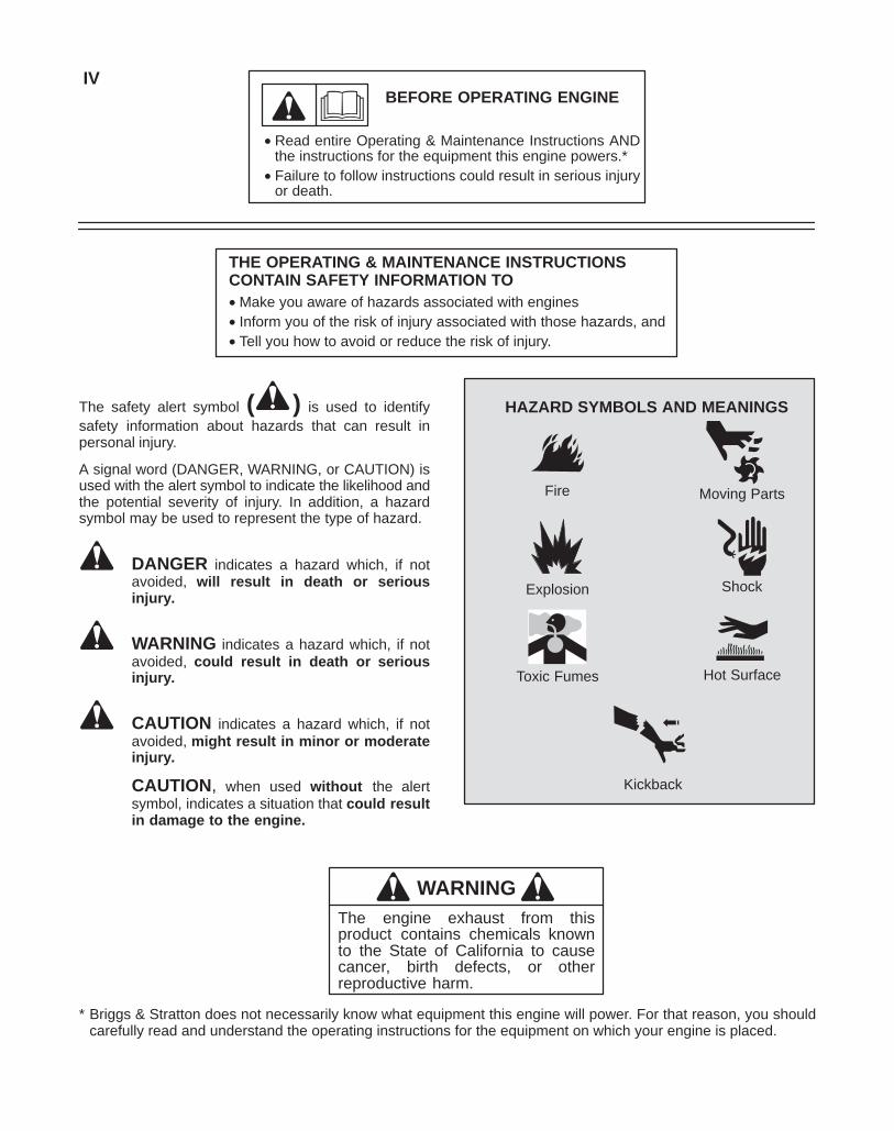
BEFORE OPERATING ENGINE
• Read entire Operating & Maintenance Instructions ANDthe instructions for the equipment this engine powers.*
• Failure to follow instructions could result in serious injuryor death.
THE OPERATING & MAINTENANCE INSTRUCTIONSCONTAIN SAFETY INFORMATION TO• Make you aware of hazards associated with engines• Inform you of the risk of injury associated with those hazards, and• Tell you how to avoid or reduce the risk of injury.
IV
The safety alert symbol ( ) is used to identifysafety information about hazards that can result inpersonal injury.
A signal word (DANGER, WARNING, or CAUTION) isused with the alert symbol to indicate the likelihood andthe potential severity of injury. In addition, a hazardsymbol may be used to represent the type of hazard.
DANGER indicates a hazard which, if notavoided, will result in death or seriousinjury.
WARNING indicates a hazard which, if notavoided, could result in death or seriousinjury.
CAUTION indicates a hazard which, if notavoided, might result in minor or moderateinjury.
CAUTION, when used without the alertsymbol, indicates a situation that could resultin damage to the engine.
HAZARD SYMBOLS AND MEANINGS
Explosion
Toxic Fumes
Moving Parts
Shock
Hot Surface
Kickback
Fire
WARNINGThe engine exhaust from thisproduct contains chemicals knownto the State of California to causecancer, birth defects, or otherreproductive harm.
* Briggs & Stratton does not necessarily know what equipment this engine will power. For that reason, you shouldcarefully read and understand the operating instructions for the equipment on which your engine is placed.
V
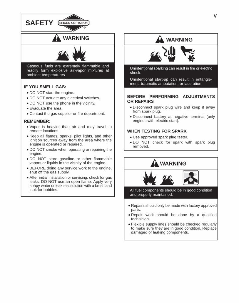
SAFETY
WARNING
Gaseous fuels are extremely flammable andreadily form explosive air-vapor mixtures atambient temperatures.
IF YOU SMELL GAS:• DO NOT start the engine.• DO NOT actuate any electrical switches.• DO NOT use the phone in the vicinity.• Evacuate the area.• Contact the gas supplier or fire department.
REMEMBER:• Vapor is heavier than air and may travel to
remote locations.• Keep all flames, sparks, pilot lights, and other
ignition sources away from the area where theengine is operated or repaired.
• DO NOT smoke when operating or repairing theengine.
• DO NOT store gasoline or other flammablevapors or liquids in the vicinity of the engine.
• BEFORE doing any service work to the engine,shut off the gas supply.
• After initial installation or servicing, check for gasleaks. DO NOT use an open flame. Apply verysoapy water or leak test solution with a brush andlook for bubbles.
WARNING
Unintentional sparking can result in fire or electricshock.
Unintentional start-up can result in entangle-ment, traumatic amputation, or laceration.
BEFORE PERFORMING ADJUSTMENTSOR REPAIRS• Disconnect spark plug wire and keep it away
from spark plug.• Disconnect battery at negative terminal (only
engines with electric start).
WHEN TESTING FOR SPARK• Use approved spark plug tester.• DO NOT check for spark with spark plug
removed.
All fuel components should be in good conditionand properly maintained.
WARNING
• Repairs should only be made with factory approvedparts.
• Repair work should be done by a qualifiedtechnician.
• Flexible supply lines should be checked regularlyto make sure they are in good condition. Replacedamaged or leaking components.
VI
SAFETY
WARNING
Engines give off carbon monoxide, an odorless,colorless, poison gas.
Breathing carbon monoxide can cause nausea,fainting or death.
• Start and run engine outdoors.• DO NOT start or run engine in enclosed area,
even if doors or windows are open.• Inhalation of high concentrations of vapor, even
for short periods, can cause unconsciousnessor might prove fatal.
• Inhalation may cause irritation to the nose andthroat, headache, nausea, vomiting, dizziness,and drowsiness.
• Unconsciousness or asphyxiation may result inpoorly ventilated areas or confined spaces.
WARNING
Running engines produce heat. Engine parts,especially muffler, become extremely hot.
Severe thermal burns can occur on contact.
Combustible debris, such as leaves, grass,brush, etc. can catch fire.
• Allow muffler, engine cylinder and fins to coolbefore touching.
• Remove accumulated combustibles from muf-fler area and cylinder area.
• Install and maintain, in working order, a sparkarrester before using equipment on forest-cov-ered, grass-covered, brush-covered unim-proved land. The state of California requires this(Section 4442 of the California Public Re-sources Code). Other states may have similarlaws. Federal laws apply on federal land.
WARNING
Wear eye protection when doing repair work.
Frostbite can result from skin/eye contact withleaking LP liquid.
°F -20 0 20 40 60 80 100
°C -30 -20 -10 0 10 20 30 40
STARTING TEMPERATURE RANGE ANTICIPATED BEFORE NEXT OIL CHANGE
*
**
32
* CAUTION: Air cooled engines run hotter thanautomotive engines. The use of non-syntheticmulti-viscosity oils (5W-30, 10W-30, etc.) intemperatures above 40° F (4° C) will result in higher thannormal oil consumption. When using a multi-viscosity oil,check oil level more frequently.
** CAUTION: SAE 30 oil, if used below 40° F (4° C), willresult in hard starting and possible engine bore damagedue to inadequate lubrication.
SAE Viscosity Grades
Note: Synthetic oil meeting ILSAC GF-2, API certi-fication mark and API service symbol (shown at left)with “SJ/CF ENERGY CONSERVING” or higher, is anacceptable oil at all temperatures. Use of syntheticoil does not alter required oil change intervals.
1
1
Section 1GENERAL INFORMATION
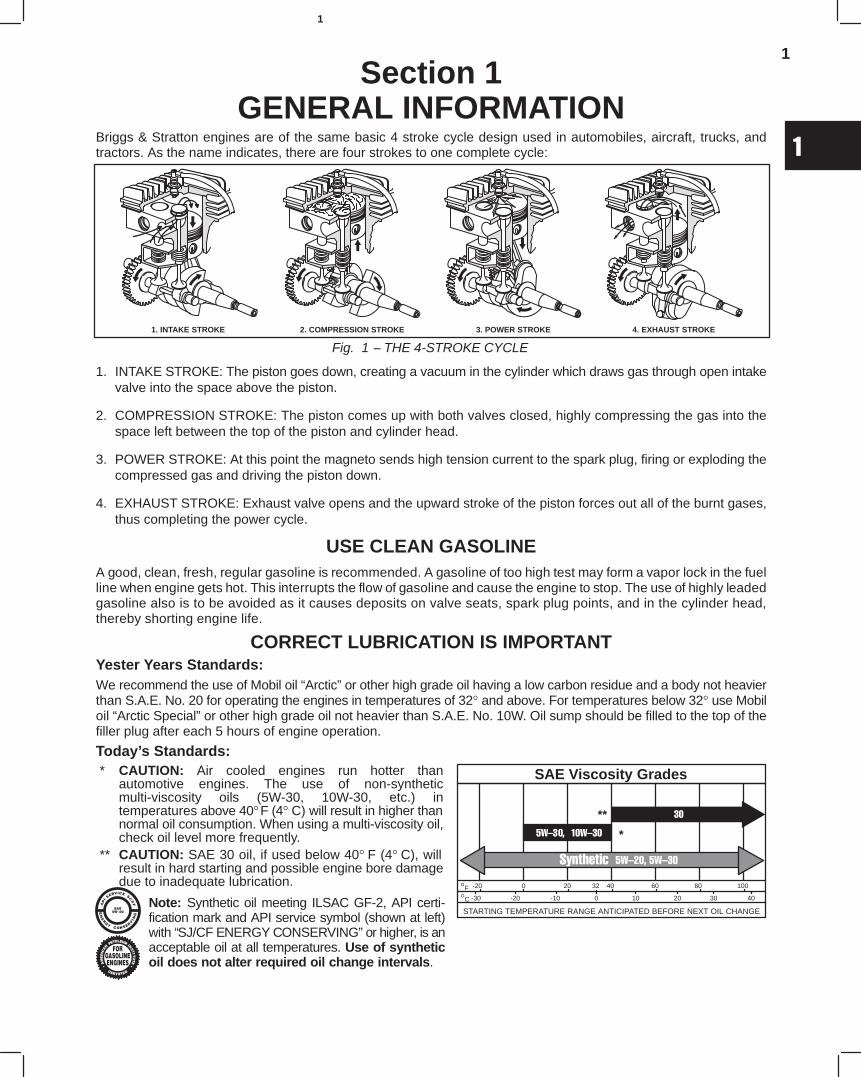
Briggs & Stratton engines are of the same basic 4 stroke cycle design used in automobiles, aircraft, trucks, andtractors. As the name indicates, there are four strokes to one complete cycle:
Fig. 1 − THE 4-STROKE CYCLE
1. INTAKE STROKE 2. COMPRESSION STROKE 3. POWER STROKE 4. EXHAUST STROKE
1. INTAKE STROKE: The piston goes down, creating a vacuum in the cylinder which draws gas through open intakevalve into the space above the piston.
2. COMPRESSION STROKE: The piston comes up with both valves closed, highly compressing the gas into thespace left between the top of the piston and cylinder head.
3. POWER STROKE: At this point the magneto sends high tension current to the spark plug, firing or exploding thecompressed gas and driving the piston down.
4. EXHAUST STROKE: Exhaust valve opens and the upward stroke of the piston forces out all of the burnt gases,thus completing the power cycle.
USE CLEAN GASOLINEA good, clean, fresh, regular gasoline is recommended. A gasoline of too high test may form a vapor lock in the fuelline when engine gets hot. This interrupts the flow of gasoline and cause the engine to stop. The use of highly leadedgasoline also is to be avoided as it causes deposits on valve seats, spark plug points, and in the cylinder head,thereby shorting engine life.
CORRECT LUBRICATION IS IMPORTANTYester Years Standards:We recommend the use of Mobil oil “Arctic” or other high grade oil having a low carbon residue and a body not heavierthan S.A.E. No. 20 for operating the engines in temperatures of 32° and above. For temperatures below 32° use Mobiloil “Arctic Special” or other high grade oil not heavier than S.A.E. No. 10W. Oil sump should be filled to the top of thefiller plug after each 5 hours of engine operation.
Today’s Standards:
2
1
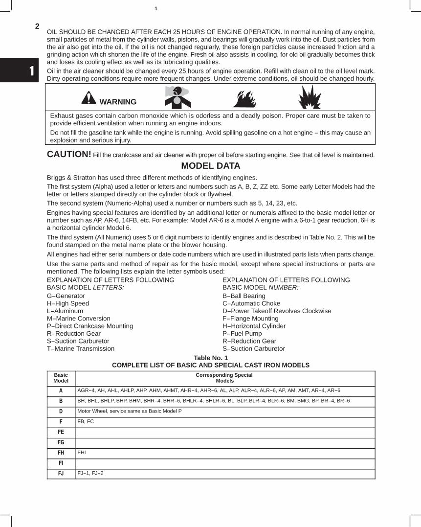
OIL SHOULD BE CHANGED AFTER EACH 25 HOURS OF ENGINE OPERATION. In normal running of any engine,small particles of metal from the cylinder walls, pistons, and bearings will gradually work into the oil. Dust particles fromthe air also get into the oil. If the oil is not changed regularly, these foreign particles cause increased friction and agrinding action which shorten the life of the engine. Fresh oil also assists in cooling, for old oil gradually becomes thickand loses its cooling effect as well as its lubricating qualities.Oil in the air cleaner should be changed every 25 hours of engine operation. Refill with clean oil to the oil level mark.Dirty operating conditions require more frequent changes. Under extreme conditions, oil should be changed hourly.
WARNING
Exhaust gases contain carbon monoxide which is odorless and a deadly poison. Proper care must be taken toprovide efficient ventilation when running an engine indoors.
Do not fill the gasoline tank while the engine is running. Avoid spilling gasoline on a hot engine − this may cause anexplosion and serious injury.
CAUTION! Fill the crankcase and air cleaner with proper oil before starting engine. See that oil level is maintained.
MODEL DATABriggs & Stratton has used three different methods of identifying engines.The first system (Alpha) used a letter or letters and numbers such as A, B, Z, ZZ etc. Some early Letter Models had theletter or letters stamped directly on the cylinder block or flywheel.The second system (Numeric-Alpha) used a number or numbers such as 5, 14, 23, etc.
Engines having special features are identified by an additional letter or numerals affixed to the basic model letter ornumber such as AP, AR-6, 14FB, etc. For example: Model AR-6 is a model A engine with a 6-to-1 gear reduction, 6H isa horizontal cylinder Model 6.
The third system (All Numeric) uses 5 or 6 digit numbers to identify engines and is described in Table No. 2. This will befound stamped on the metal name plate or the blower housing.
All engines had either serial numbers or date code numbers which are used in illustrated parts lists when parts change.
Use the same parts and method of repair as for the basic model, except where special instructions or parts arementioned. The following lists explain the letter symbols used:EXPLANATION OF LETTERS FOLLOWINGBASIC MODEL LETTERS:G−GeneratorH−High SpeedL−AluminumM−Marine ConversionP−Direct Crankcase MountingR−Reduction GearS−Suction CarburetorT−Marine Transmission
EXPLANATION OF LETTERS FOLLOWING BASIC MODEL NUMBER:B−Ball BearingC−Automatic ChokeD−Power Takeoff Revolves ClockwiseF−Flange MountingH−Horizontal CylinderP−Fuel PumpR−Reduction GearS−Suction Carburetor
Table No. 1COMPLETE LIST OF BASIC AND SPECIAL CAST IRON MODELS
BasicModel
Corresponding Special Models
A AGR−4, AH, AHL, AHLP, AHP, AHM, AHMT, AHR−4, AHR−6, AL, ALP, ALR−4, ALR−6, AP, AM, AMT, AR−4, AR−6
B BH, BHL, BHLP, BHP, BHM, BHR−4, BHR−6, BHLR−4, BHLR−6, BL, BLP, BLR−4, BLR−6, BM, BMG, BP, BR−4, BR−6
D Motor Wheel, service same as Basic Model P
F FB, FC
FE
FG
FH FHI
FI
FJ FJ−1, FJ−2

3
1
MODEL DATA (Cont’d.)
Table No. 1COMPLETE LIST OF BASIC AND SPECIAL CAST IRON MODELS (CONT’D.)
BasicModel
Corresponding Special Models
H HM
I IB, IBHP, IBLP, IBP,IL, ILR-6, IMT, IP, IR-6, IS, IPR1.6, IPR6
K KL, KLP, KLR-4, KLR-6,KM, KP, KR-4, KR-6
L LA
M MB, MC, MF, MH
N NP, NR-2, NR-6, NPR1.6, NPR6
NS NSPR1.6, NSPR6
P PB
Q
R RC
S SC (similar to T)
T TA
U UR-2, UR-6
W WA
WI WIBP, WR-6, WIPR1.6, WIPR6
WM WMG
WMB WBG
WMI WMIP
Y
Z ZH, ZHL, ZHLP, ZHP, ZHLR-4, ZHLR-6, ZHM, ZHR-4, ZHR-6, ZL, ZLP, ZLR-4, ZLR-6, ZM, ZP, ZR-4, ZR-6
ZZ ZZL, ZZLP, ZZP, ZZR
5 5S
6 6H, 6HF, 6HFB, 6HS, 6HSF, 6S
8 8FB, 8HF, 8R4D, 8R6
9 9B, 9FB, 9FBC, 9FBP, 9P, 9R6, 9R6D
14 14B, 14F, 14FB, 14FBC, 14FBPC, 14FBP, 14P, 14R6, 14R6D
23 23B, 23FB, 23FBP, 23FBPC, 23P, 23PC, 23R6, 23R6D
4
1
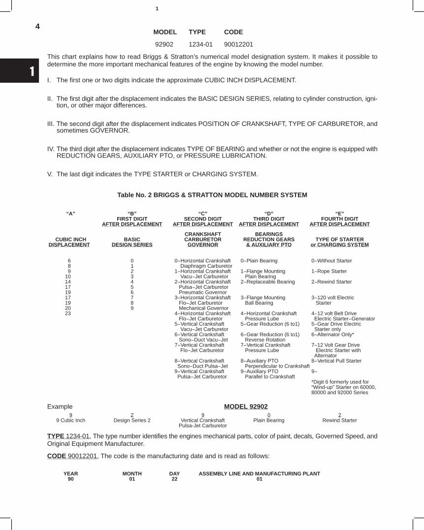
MODEL TYPE CODE
92902 1234-01 90012201
This chart explains how to read Briggs & Stratton’s numerical model designation system. It makes it possible todetermine the more important mechanical features of the engine by knowing the model number.
I. The first one or two digits indicate the approximate CUBIC INCH DISPLACEMENT.
II. The first digit after the displacement indicates the BASIC DESIGN SERIES, relating to cylinder construction, igni-tion, or other major differences.
III. The second digit after the displacement indicates POSITION OF CRANKSHAFT, TYPE OF CARBURETOR, andsometimes GOVERNOR.
IV. The third digit after the displacement indicates TYPE OF BEARING and whether or not the engine is equipped withREDUCTION GEARS, AUXILIARY PTO, or PRESSURE LUBRICATION.
V. The last digit indicates the TYPE STARTER or CHARGING SYSTEM.
Table No. 2 BRIGGS & STRATTON MODEL NUMBER SYSTEM
“A” “B” “C” “D” “E”FIRST DIGIT SECOND DIGIT THIRD DIGIT FOURTH DIGIT
AFTER DISPLACEMENT AFTER DISPLACEMENT AFTER DISPLACEMENT AFTER DISPLACEMENT
CRANKSHAFT BEARINGSCUBIC INCH BASIC CARBURETOR REDUCTION GEARS TYPE OF STARTER
DISPLACEMENT DESIGN SERIES GOVERNOR & AUXILIARY PTO or CHARGING SYSTEM
6 0 0−Horizontal Crankshaft 0−Plain Bearing 0−Without Starter8 1 Diaphragm Carburetor9 2 1−Horizontal Crankshaft 1−Flange Mounting 1−Rope Starter
10 3 Vacu−Jet Carburetor Plain Bearing14 4 2−Horizontal Crankshaft 2−Replaceable Bearing 2−Rewind Starter17 5 Pulsa−Jet Carburetor19 6 Pneumatic Governor17 7 3−Horizontal Crankshaft 3−Flange Mounting 3−120 volt Electric19 8 Flo−Jet Carburetor Ball Bearing Starter20 9 Mechanical Governor23 4−Horizontal Crankshaft 4−Horizontal Crankshaft 4−12 volt Belt Drive
Flo−Jet Carburetor Pressure Lube Electric Starter−Generator5−Vertical Crankshaft 5−Gear Reduction (6 to1) 5−Gear Drive Electric Vacu−Jet Carburetor Starter only6−Vertical Crankshaft 6−Gear Reduction (6 to1) 6−Alternator Only* Sono−Duct Vacu−Jet Reverse Rotation7−Vertical Crankshaft 7−Vertical Crankshaft 7−12 Volt Gear Drive Flo−Jet Carburetor Pressure Lube Electric Starter with
Alternator8−Vertical Crankshaft 8−Auxiliary PTO 8−Vertical Pull Starter Sono−Duct Pulsa−Jet Perpendicular to Crankshaft9−Vertical Crankshaft 9−Auxiliary PTO 9− Pulsa−Jet Carburetor Parallel to Crankshaft
*Digit 6 formerly used for“Wind-up” Starter on 60000, 80000 and 92000 Series
Example MODEL 929029 2 9 0 2
9 Cubic Inch Design Series 2 Vertical Crankshaft Plain Bearing Rewind StarterPulsa-Jet Carburetor
TYPE 1234-01, The type number identifies the engines mechanical parts, color of paint, decals, Governed Speed, andOriginal Equipment Manufacturer.
CODE 90012201, The code is the manufacturing date and is read as follows:
YEAR MONTH DAY ASSEMBLY LINE AND MANUFACTURING PLANT90 01 22 01

5
1
Table No. 3OVERHAUL AND TUNE-UP PROCEDURE
We recommend that the following procedure be followed in overhauling all Briggs & Stratton engines. It ispossible, of course, that these operations be performed in different sequence, but we believe thatperforming the steps in the same order every time increases efficiency. All steps may not be necessary onevery engine. The condition of the engine will determine what should be done. However, the steps listed inthe Tune-up (see page 8) should be performed in every case. The operations listed apply to modelsindicated by an “X.”
The words “remove and inspect” or “reassemble,” should be understood in eachstep unless another operation such as “check ” “test ” or “adjust” is indicated
MODELstep unless another operation such as “check,” “test,” or “adjust” is indicated.
9
DISASSEMBLYN8
91423 ZZ B
56
NSWI A
1 Air Cleaner X X X X X X X
2 Muffler (Remove only when necessary.) X X X X X X X
3 Fuel Pipe X X X X X X
4 Fuel filter yoke-bowl-gasket-screen only X X X X X
5 Tank outlet assembly X
6 Air cleaner elbow or pipe X X X X X
7 Carburetor and linkage X X X X X X X
8 Check space between upper and lower bodiesCheck throttle shaft and bushing for wear
X X X X X
9 Disassemble carburetor X X X X X
10 Spin flywheel to check compression X X X X X X X
11 Spark plug. adjust gap, clean, test gap .025” X X X X X X X
12 Carburetor intake elbow X X X X X
13 Fuel Tank (Remove from tank bracket only when tank is to be replaced.) X X X X X X X
14 Rope starter pulley X X X X
15 Blower housing X X X X X X X
16 Check air gap, armature to flywheel X X X
17 Valve cover X X X X X X X
18 Breather (Cover, strainer and moss only on 9 −14 − 23 − A − B − ZZ) X X X X X X X
19 Cylinder head and shield X X X X X X X
20 Check tappet clearance X X X X X X X
21 Rope starter pulley X X X
22 Flywheel X X X X X X X
23 Breaker point cover X X X X X X X
24 Check breaker point gap (Gap .020”). (For replacement of points, see steps 67& 73.)
X X X X X X X
25 Check breaker point plunger hole. X X X X X X
26 Breaker box X
27 Drain oil X X X X X X X
28 Base X X X X X X X
29 Mechanical governor parts X X X X X
30 Connecting rod and piston from engine X X X X X X X
31 Check end play X X X X X X X
6
1
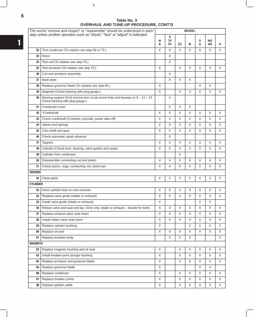
Table No. 3OVERHAUL AND TUNE-UP PROCEDURE, CONT’D
The words “remove and inspect” or “reassemble” should be understood in eachstep unless another operation such as “check ” “test” or “adjust” is indicated
MODELstep unless another operation such as “check,” “test” or “adjust” is indicated.
N8
91423 ZZ B
56
NSWI A
32 Test condenser (To replace see step 66 or 72.) X X X X X X X
33 Rotor X
34 Test coil (To replace see step 75.) X
35 Test armature (To replace see step 75.) X X X X X X
36 Coil and armature assembly X
37 Back plate X X X
38 Replace governor blade (To replace see step 65.) X X X
39 Magneto (Check bearing with plug gauge.) X X X X X X
40 Bearing support (First remove burr at set screw hole and keyway on 9 − 14 − 23.Check bearing with plug gauge.)
X
41 Crankcase cover X X X
42 *Crankshaft X X X X X X X
43 Check crankshaft (Crankpin, journals, power take-off) X X X X X X X
44 Valves and springs X X X X X X X
45 Cam shaft and gear X X X X X X X
46 Check automatic spark advance X
47 Tappets X X X X X X X
48 Cylinder (Check bore, bearing, valve guides and seats) X X X X X X X
49 Cylinder from crankcase X
50 Disassemble connecting rod and piston X X X X X X X
51 Check piston, rings, connecting rod, piston pin X X X X X X X
REPAIRS
52 Clean parts X X X X X X X
CYLINDER
53 Hone cylinder bore to next oversize X X X X X X X
54 Replace valve guide (intake or exhaust) X X X X X X X
55 Install valve guide (intake or exhaust) X X X
56 Reface valve and seat and lap. (One only, intake or exhaust − double for both) X X X X X X X
57 Replace exhaust valve seat insert X X X X X X X
58 Install intake valve seat insert X X X X X X X
59 Replace cylinder bushing X X X X X
60 Replace oil seal X X X X X X X
61 Replace breather body X X X X
MAGNETO
62 Replace magneto bushing and oil seal X X X X X X
63 Install breaker point plunger bushing X X X X X X
64 Replace armature and governor blade X X X X X X
65 Replace governor blade X X X
66 Replace condenser X X X X X X
67 Replace breaker points X X X X X X
68 Replace ignition cable X X X X X X
7
1
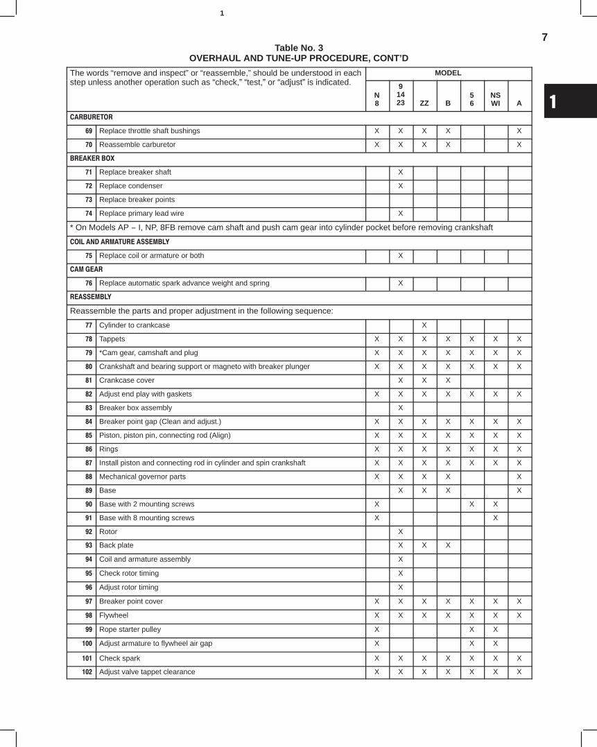
Table No. 3OVERHAUL AND TUNE-UP PROCEDURE, CONT’D
The words “remove and inspect” or “reassemble,” should be understood in eacht l th ti h “ h k ” “t t ” “ dj t” i i di t d
MODELpstep unless another operation such as “check,” “test,” or “adjust” is indicated.
N8
91423 ZZ B
56
NSWI A
CARBURETOR
69 Replace throttle shaft bushings X X X X X
70 Reassemble carburetor X X X X X
BREAKER BOX
71 Replace breaker shaft X
72 Replace condenser X
73 Replace breaker points
74 Replace primary lead wire X
* On Models AP − I, NP, 8FB remove cam shaft and push cam gear into cylinder pocket before removing crankshaft
COIL AND ARMATURE ASSEMBLY
75 Replace coil or armature or both X
CAM GEAR
76 Replace automatic spark advance weight and spring X
REASSEMBLY
Reassemble the parts and proper adjustment in the following sequence:
77 Cylinder to crankcase X
78 Tappets X X X X X X X
79 *Cam gear, camshaft and plug X X X X X X X
80 Crankshaft and bearing support or magneto with breaker plunger X X X X X X X
81 Crankcase cover X X X
82 Adjust end play with gaskets X X X X X X X
83 Breaker box assembly X
84 Breaker point gap (Clean and adjust.) X X X X X X X
85 Piston, piston pin, connecting rod (Align) X X X X X X X
86 Rings X X X X X X X
87 Install piston and connecting rod in cylinder and spin crankshaft X X X X X X X
88 Mechanical governor parts X X X X X
89 Base X X X X
90 Base with 2 mounting screws X X X
91 Base with 8 mounting screws X X
92 Rotor X
93 Back plate X X X
94 Coil and armature assembly X
95 Check rotor timing X
96 Adjust rotor timing X
97 Breaker point cover X X X X X X X
98 Flywheel X X X X X X X
99 Rope starter pulley X X X
100 Adjust armature to flywheel air gap X X X
101 Check spark X X X X X X X
102 Adjust valve tappet clearance X X X X X X X
8
1
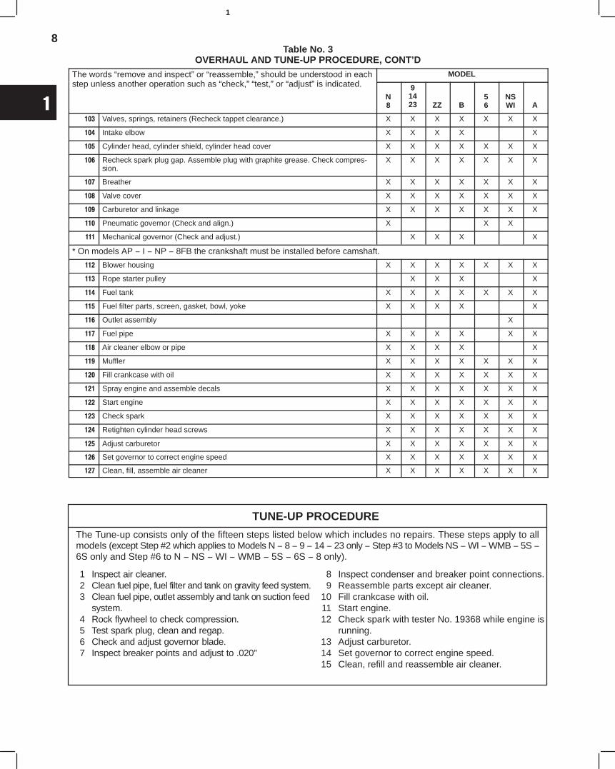
Table No. 3OVERHAUL AND TUNE-UP PROCEDURE, CONT’D
The words “remove and inspect” or “reassemble,” should be understood in eacht l th ti h “ h k ” “t t ” “ dj t” i i di t d
MODELpstep unless another operation such as “check,” “test,” or “adjust” is indicated.
N8
91423 ZZ B
56
NSWI A
103 Valves, springs, retainers (Recheck tappet clearance.) X X X X X X X
104 Intake elbow X X X X X
105 Cylinder head, cylinder shield, cylinder head cover X X X X X X X
106 Recheck spark plug gap. Assemble plug with graphite grease. Check compres-sion.
X X X X X X X
107 Breather X X X X X X X
108 Valve cover X X X X X X X
109 Carburetor and linkage X X X X X X X
110 Pneumatic governor (Check and align.) X X X
111 Mechanical governor (Check and adjust.) X X X X
* On models AP − I − NP − 8FB the crankshaft must be installed before camshaft.
112 Blower housing X X X X X X X
113 Rope starter pulley X X X X
114 Fuel tank X X X X X X X
115 Fuel filter parts, screen, gasket, bowl, yoke X X X X X
116 Outlet assembly X
117 Fuel pipe X X X X X X
118 Air cleaner elbow or pipe X X X X X
119 Muffler X X X X X X X
120 Fill crankcase with oil X X X X X X X
121 Spray engine and assemble decals X X X X X X X
122 Start engine X X X X X X X
123 Check spark X X X X X X X
124 Retighten cylinder head screws X X X X X X X
125 Adjust carburetor X X X X X X X
126 Set governor to correct engine speed X X X X X X X
127 Clean, fill, assemble air cleaner X X X X X X X
TUNE-UP PROCEDURE
1 Inspect air cleaner.2 Clean fuel pipe, fuel filter and tank on gravity feed system.3 Clean fuel pipe, outlet assembly and tank on suction feed
system.4 Rock flywheel to check compression.5 Test spark plug, clean and regap.6 Check and adjust governor blade.7 Inspect breaker points and adjust to .020”
The Tune-up consists only of the fifteen steps listed below which includes no repairs. These steps apply to allmodels (except Step #2 which applies to Models N − 8 − 9 − 14 − 23 only − Step #3 to Models NS − WI − WMB − 5S −6S only and Step #6 to N − NS − WI − WMB − 5S − 6S − 8 only).
8 Inspect condenser and breaker point connections.9 Reassemble parts except air cleaner.
10 Fill crankcase with oil.11 Start engine.12 Check spark with tester No. 19368 while engine is
running.13 Adjust carburetor.14 Set governor to correct engine speed.15 Clean, refill and reassemble air cleaner.
9
1
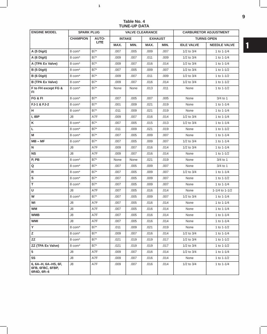
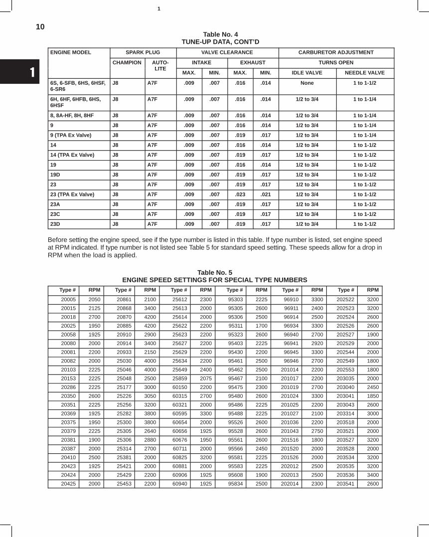
Table No. 4TUNE-UP DATA
ENGINE MODEL SPARK PLUG VALVE CLEARANCE CARBURETOR ADJUSTMENT
CHAMPION AUTO-LITE
INTAKE EXHAUST TURNS OPENLITE
MAX. MIN. MAX. MIN. IDLE VALVE NEEDLE VALVE
A (5 Digit) 8 com* B7* .007 .005 .009 .007 1/2 to 3/4 1 to 1-1/4
A (6 Digit) 8 com* B7* .009 .007 .011 .009 1/2 to 3/4 1 to 1-1/4
A (TPA Ex Valve) 8 com* B7* .009 .007 .016 .014 1/2 to 3/4 1 to 1-1/4
B (5 Digit) 8 com* B7* .007 .005 .009 .007 1/2 to 3/4 1 to 1-1/2
B (6 Digit) 8 com* B7* .009 .007 .011 .009 1/2 to 3/4 1 to 1-1/2
B (TPA Ex Valve) 8 com* B7* .009 .007 .016 .014 1/2 to 3/4 1 to 1-1/2
F to FH except FG &FI
8 com* B7* None None .013 .011 None 1 to 1-1/2
FG & FI 8 com* B7* .007 .005 .007 .005 None 3/4 to 1
FJ-1 & FJ-2 8 com* B7* .001 .009 .021 .019 None 1 to 1-1/4
H 8 com* B7* .011 .009 .021 .019 None 1 to 1-1/4
I, IBP J8 A7F .009 .007 .016 .014 1/2 to 3/4 1 to 1-1/4
K 8 com* B7* .007 .005 .015 .013 1/2 to 3/4 1 to 1-1/4
L 8 com* B7* .011 .009 .021 .019 None 1 to 1-1/2
M 8 com* B7* .007 .005 .009 .007 None 1 to 1-1/4
MB − MF 8 com* B7* .007 .005 .009 .007 1/2 to 3/4 1 to 1-1/4
N J8 A7F .009 .007 .016 .014 1/2 to 3/4 1 to 1-1/4
NS J8 A7F .009 .007 .016 .014 None 1 to 1-1/2
P, PB 8 com* B7* None None .021 .019 None 3/4 to 1
Q 8 com* B7* .007 .005 .009 .007 None 3/4 to 1
R 8 com* B7* .007 .005 .009 .007 1/2 to 3/4 1 to 1-1/4
S 8 com* B7* .007 .005 .009 .007 None 1 to 1-1/2
T 8 com* B7* .007 .005 .009 .007 None 1 to 1-1/4
U J8 A7F .007 .005 .016 .014 None 1-1/4 to 1-1/2
W 8 com* B7* .007 .005 .009 .007 1/2 to 3/4 1 to 1-1/4
WI J8 A7F .007 .005 .016 .014 None 1 to 1-1/4
WM J8 A7F .007 .005 .016 .014 None 1 to 1-1/4
WMB J8 A7F .007 .005 .016 .014 None 1 to 1-1/4
WMI J8 A7F .007 .005 .016 .014 None 1 to 1-1/4
Y 8 com* B7* .011 .009 .021 .019 None 1 to 1-1/2
Z 8 com* B7* .009 .007 .016 .014 1/2 to 3/4 1 to 1-1/4
ZZ 8 com* B7* .021 .019 .019 .017 1/2 to 3/4 1 to 1-1/2
ZZ (TPA Ex Valve) 8 com* B7* .021 .019 .019 .017 1/2 to 3/4 1 to 1-1/2
5 J8 A7F .009 .007 .016 .014 1/2 to 3/4 1 to 1-1/4
5S J8 A7F .009 .007 .016 .014 None 1 to 1-1/2
6, 6A−H, 6A−HS, 6F,6FB, 6FBC, 6FBP,6R4D, 6R−6
J8 A7F .009 .007 .016 .014 1/2 to 3/4 1 to 1-1/4
10
1
Table No. 4TUNE-UP DATA, CONT’D
ENGINE MODEL SPARK PLUG VALVE CLEARANCE CARBURETOR ADJUSTMENT
CHAMPION AUTO-LITE
INTAKE EXHAUST TURNS OPENLITE
MAX. MIN. MAX. MIN. IDLE VALVE NEEDLE VALVE
6S, 6-SFB, 6HS, 6HSF,6-SR6
J8 A7F .009 .007 .016 .014 None 1 to 1-1/2
6H, 6HF, 6HFB, 6HS,6HSF
J8 A7F .009 .007 .016 .014 1/2 to 3/4 1 to 1-1/4
8, 8A-HF, 8H, 8HF J8 A7F .009 .007 .016 .014 1/2 to 3/4 1 to 1-1/4
9 J8 A7F .009 .007 .016 .014 1/2 to 3/4 1 to 1-1/4
9 (TPA Ex Valve) J8 A7F .009 .007 .019 .017 1/2 to 3/4 1 to 1-1/4
14 J8 A7F .009 .007 .016 .014 1/2 to 3/4 1 to 1-1/2
14 (TPA Ex Valve) J8 A7F .009 .007 .019 .017 1/2 to 3/4 1 to 1-1/2
19 J8 A7F .009 .007 .016 .014 1/2 to 3/4 1 to 1-1/2
19D J8 A7F .009 .007 .019 .017 1/2 to 3/4 1 to 1-1/2
23 J8 A7F .009 .007 .019 .017 1/2 to 3/4 1 to 1-1/2
23 (TPA Ex Valve) J8 A7F .009 .007 .023 .021 1/2 to 3/4 1 to 1-1/2
23A J8 A7F .009 .007 .019 .017 1/2 to 3/4 1 to 1-1/2
23C J8 A7F .009 .007 .019 .017 1/2 to 3/4 1 to 1-1/2
23D J8 A7F .009 .007 .019 .017 1/2 to 3/4 1 to 1-1/2
Before setting the engine speed, see if the type number is listed in this table. If type number is listed, set engine speedat RPM indicated. If type number is not listed see Table 5 for standard speed setting. These speeds allow for a drop inRPM when the load is applied.
Table No. 5ENGINE SPEED SETTINGS FOR SPECIAL TYPE NUMBERS
Type # RPM Type # RPM Type # RPM Type # RPM Type # RPM Type # RPM
20005 2050 20861 2100 25612 2300 95303 2225 96910 3300 202522 3200
20015 2125 20868 3400 25613 2000 95305 2600 96911 2400 202523 3200
20018 2700 20870 4200 25614 2000 95306 2500 96914 2500 202524 2600
20025 1950 20885 4200 25622 2200 95311 1700 96934 3300 202526 2600
20058 1925 20910 2900 25623 2200 95323 2600 96940 2700 202527 1900
20080 2000 20914 3400 25627 2200 95403 2225 96941 2920 202529 2000
20081 2200 20933 2150 25629 2200 95430 2200 96945 3300 202544 2000
20082 2000 25030 4000 25634 2200 95461 2500 96946 2700 202549 1800
20103 2225 25046 4000 25649 2400 95462 2500 201014 2200 202553 1800
20153 2225 25048 2500 25859 2075 95467 2100 201017 2200 203035 2000
20286 2225 25177 3000 60150 2200 95475 2300 201019 2700 203040 2450
20350 2600 25226 3050 60315 2700 95480 2600 201024 3300 203041 1850
20351 2225 25256 3200 60321 2000 95486 2225 201025 2200 203043 2600
20369 1925 25282 3800 60595 3300 95488 2225 201027 2100 203314 3000
20375 1950 25300 3800 60654 2000 95526 2600 201036 2200 203518 2000
20379 2225 25305 2640 60656 1925 95528 2600 201043 2750 203521 2000
20381 1900 25306 2880 60676 1950 95561 2600 201516 1800 203527 3200
20387 2000 25314 2700 60711 2000 95566 2450 201520 2000 203528 2000
20410 2500 25381 2000 60825 3200 95581 2225 201526 2000 203534 3200
20423 1925 25421 2000 60881 2000 95583 2225 202012 2500 203535 3200
20424 2000 25429 2200 60906 1925 95608 1900 202013 2500 203536 3400
20425 2000 25453 2200 60940 1925 95834 2500 202014 2300 203541 2600

11
1
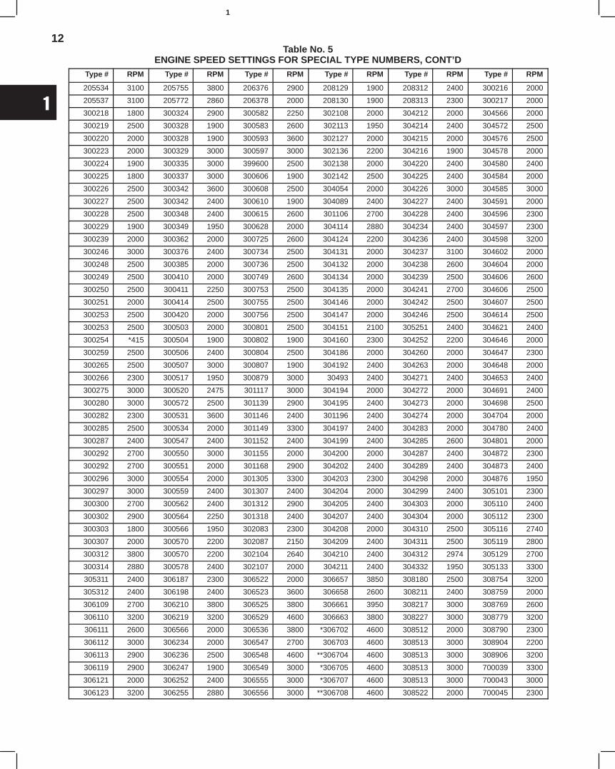
Table No. 5ENGINE SPEED SETTINGS FOR SPECIAL TYPE NUMBERS, CONT’D
Type # RPM Type # RPM Type # RPM Type # RPM Type # RPM Type # RPM
20484 2000 25457 2200 60975 2200 95853 2920 202015 2900 204089 2500
20515 2600 25458 2200 95011 3600 95910 2400 202016 2000 205063 3800
20795 2200 25459 2000 95065 2125 95919 2400 202022 2700 205070 3700
20797 2000 25460 2200 95090 2000 95925 1600 202024 2450 205085 3200
20810 1850 25461 2000 95158 3500 95938 2500 202025 2000 205091 3700
20811 2300 25463 2200 95170 3000 95939 2300 202029 2700 205099 3200
20813 2300 25465 2000 95172 1900 9946 2500 202034 2000 205113 2400
20814 2300 25567 2000 95204 2000 9965 2700 202035 2400 205114 3200
20815 2000 25604 2200 95208 2225 95965 2700 202037 1900 205128 3200
20818 2200 25605 2200 95261 3000 95967 3300 202040 1800 205141 4500
20819 2000 25606 1850 95285 2000 95970 3300 202054 2400 205142 3700
20820 1950 25607 2000 95293 2000 95971 2700 202312 3000 205186 3400
20849 1950 25608 2200 95294 2000 95975 3300 202514 2000 205270 2630
20860 2100 25609 2000 95302 2600 95981 2700 202517 1850 205274 2640
203035 200 205557 2400 *205776 4600 206382 3700 208148 1900 208324 2600
203040 2450 205562 2900 205777 1900 206383 3000 208151 2000 208605 2600
203041 1850 205563 2250 205778 4600 206386 3000 208151 2000 208609 2600
203043 2600 295564 3500 205779 4600 206464 2500 208157 2000 300065 2000
203314 3000 205567 3200 205782 2700 207010 3200 208157 2000 300085 2000
203518 2000 205571 2800 205786 2800 207012 3800 208159 2000 300096 3000
203521 2000 205577 2000 *205789 4600 207015 3000 208160 2200 300099 2000
203527 3200 205579 2000 206100 3300 206016 3000 208167 3000 300108 2000
203528 2000 205581 2000 206101 2700 207022 3450 208172 2400 300119 1925
203534 3200 205582 2640 206102 2700 207023 3000 208176 3200 300138 2000
203535 3200 205589 2640 206103 2700 207024 3000 208177 2400 300140 2200
203536 3400 205591 2300 206104 2700 207106 3000 208179 2600 300145 2300
203541 2600 205592 2500 206105 2700 207110 2800 208180 2000 300149 2400
204089 2500 2205593 2800 206106 2700 207119 2900 208182 1950 300150 2300
205063 3800 205599 2800 206158 3500 208055 2200 208183 3000 300155 2000
205070 3700 205600 3200 206160 3000 208057 2000 208185 4000 300176 2000
205085 3200 205605 1850 207174 2900 208058 2200 208187 3300 300177 2000
205091 3700 205608 2600 206180 3500 208059 2200 208188 2200 300181 2500
205099 3200 205610 2640 206304 3800 208064 2200 208189 2200 300183 1925
205113 2400 205624 2300 206327 3200 208065 2200 208190 2000 300185 3100
205114 3200 205626 2900 206340 3200 208066 2200 208199 2000 300188 2000
205128 3200 205627 2640 206341 3000 208068 2100 208203 2700 300193 2000
205141 4500 205631 3600 206351 3300 208069 2200 208206 2200 300194 2600
205142 3700 205635 2300 206352 4200 208070 2200 208254 2200 300199 2500
205186 3400 205644 2640 206359 4200 208071 2000 208256 2400 300201 2500
205270 2630 207010 3200 206360 4200 208072 4000 208264 3100 300203 2500
205274 2640 205657 2800 206361 3000 208077 2200 208272 2000 300205 2000
205279 3500 205659 2450 206362 3800 208080 2200 208273 2000 300207 2000
205288 3450 205663 2000 206363 3000 208082 2000 208277 2000 300208 2500
205305 2900 205675 2300 206364 3000 208084 2200 208278 2000 300209 2500
205318 3200 205676 2300 206367 3500 208108 2900 208284 2000 300210 2500
205505 2800 205678 2640 206371 3000 208114 2100 208285 4000 300211 2500
205507 3050 205678 2640 206372 3600 208116 2000 208289 1925 300213 2200
205521 3200 205683 2000 206373 3600 208117 2000 208291 1925 300214 2500
205530 3800 205754 2500 206375 2900 208118 2400 208307 2250 300215 2500
12
1
Table No. 5ENGINE SPEED SETTINGS FOR SPECIAL TYPE NUMBERS, CONT’D
Type # RPM Type # RPM Type # RPM Type # RPM Type # RPM Type # RPM
205534 3100 205755 3800 206376 2900 208129 1900 208312 2400 300216 2000
205537 3100 205772 2860 206378 2000 208130 1900 208313 2300 300217 2000
300218 1800 300324 2900 300582 2250 302108 2000 304212 2000 304566 2000
300219 2500 300328 1900 300583 2600 302113 1950 304214 2400 304572 2500
300220 2000 300328 1900 300593 3600 302127 2000 304215 2000 304576 2500
300223 2000 300329 3000 300597 3000 302136 2200 304216 1900 304578 2000
300224 1900 300335 3000 399600 2500 302138 2000 304220 2400 304580 2400
300225 1800 300337 3000 300606 1900 302142 2500 304225 2400 304584 2000
300226 2500 300342 3600 300608 2500 304054 2000 304226 3000 304585 3000
300227 2500 300342 2400 300610 1900 304089 2400 304227 2400 304591 2000
300228 2500 300348 2400 300615 2600 301106 2700 304228 2400 304596 2300
300229 1900 300349 1950 300628 2000 304114 2880 304234 2400 304597 2300
300239 2000 300362 2000 300725 2600 304124 2200 304236 2400 304598 3200
300246 3000 300376 2400 300734 2500 304131 2000 304237 3100 304602 2000
300248 2500 300385 2000 300736 2500 304132 2000 304238 2600 304604 2000
300249 2500 300410 2000 300749 2600 304134 2000 304239 2500 304606 2600
300250 2500 300411 2250 300753 2500 304135 2000 304241 2700 304606 2500
300251 2000 300414 2500 300755 2500 304146 2000 304242 2500 304607 2500
300253 2500 300420 2000 300756 2500 304147 2000 304246 2500 304614 2500
300253 2500 300503 2000 300801 2500 304151 2100 305251 2400 304621 2400
300254 *415 300504 1900 300802 1900 304160 2300 304252 2200 304646 2000
300259 2500 300506 2400 300804 2500 304186 2000 304260 2000 304647 2300
300265 2500 300507 3000 300807 1900 304192 2400 304263 2000 304648 2000
300266 2300 300517 1950 300879 3000 30493 2400 304271 2400 304653 2400
300275 3000 300520 2475 301117 3000 304194 2000 304272 2000 304691 2400
300280 3000 300572 2500 301139 2900 304195 2400 304273 2000 304698 2500
300282 2300 300531 3600 301146 2400 301196 2400 304274 2000 304704 2000
300285 2500 300534 2000 301149 3300 304197 2400 304283 2000 304780 2400
300287 2400 300547 2400 301152 2400 304199 2400 304285 2600 304801 2000
300292 2700 300550 3000 301155 2000 304200 2000 304287 2400 304872 2300
300292 2700 300551 2000 301168 2900 304202 2400 304289 2400 304873 2400
300296 3000 300554 2000 301305 3300 304203 2300 304298 2000 304876 1950
300297 3000 300559 2400 301307 2400 304204 2000 304299 2400 305101 2300
300300 2700 300562 2400 301312 2900 304205 2400 304303 2000 305110 2400
300302 2900 300564 2250 301318 2400 304207 2400 304304 2000 305112 2300
300303 1800 300566 1950 302083 2300 304208 2000 304310 2500 305116 2740
300307 2000 300570 2200 302087 2150 304209 2400 304311 2500 305119 2800
300312 3800 300570 2200 302104 2640 304210 2400 304312 2974 305129 2700
300314 2880 300578 2400 302107 2000 304211 2400 304332 1950 305133 3300
305311 2400 306187 2300 306522 2000 306657 3850 308180 2500 308754 3200
305312 2400 306198 2400 306523 3600 306658 2600 308211 2400 308759 2000
306109 2700 306210 3800 306525 3800 306661 3950 308217 3000 308769 2600
306110 3200 306219 3200 306529 4600 306663 3800 308227 3000 308779 3200
306111 2600 306566 2000 306536 3800 *306702 4600 308512 2000 308790 2300
306112 3000 306234 2000 306547 2700 306703 4600 308513 3000 308904 2200
306113 2900 306236 2500 306548 4600 **306704 4600 308513 3000 308906 3200
306119 2900 306247 1900 306549 3000 *306705 4600 308513 3000 700039 3300
306121 2000 306252 2400 306555 3000 *306707 4600 308513 3000 700043 3000
306123 3200 306255 2880 306556 3000 **306708 4600 308522 2000 700045 2300
13
1
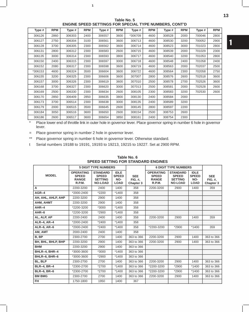
Table No. 5ENGINE SPEED SETTINGS FOR SPECIAL TYPE NUMBERS, CONT’D
Type # RPM Type # RPM Type # RPM Type # RPM Type # RPM Type # RPM
306126 2860 306303 2400 306557 3600 *306709 4600 308528 2000 700046 2800
306127 2750 306304 3100 306561 3600 306713 4600 308530 3200 700052 2900
306128 3700 306305 2300 306562 3600 306714 4600 308523 3000 701023 2800
306131 2800 306312 2300 306583 2600 306715 4600 308539 2000 701029 2300
306135 3000 306314 2300 306593 3800 306717 4600 308540 3200 701053 2800
306150 2400 306315 2300 306597 3000 306718 4600 308548 2400 701058 2400
306152 2080 306317 2300 306598 3600 306719 4600 308563 2000 702037 2500
*306153 4600 306324 3500 306604 3600 306722 4600 308564 2300 702058 2750
306155 3200 306325 2300 306606 3600 307007 2800 308576 2600 702518 3600
306157 3000 306326 2300 306619 3600 307010 2500 308578 2700 702526 3600
306168 3700 306327 2300 306620 3000 307013 2500 308581 2000 702528 2600
306169 2500 306330 2300 306634 2600 308105 2300 308583 3200 702530 2600
306170 2850 306409 2850 306635 3800 308130 2400 308584 2000
306173 3700 306514 2300 306638 3000 308135 2400 308589 3200
306179 2000 306515 3500 306645 2600 308145 2800 308597 2200
306184 3050 306516 3600 306650 2600 308154 2500 308753 2600
306186 2600 306517 3600 306654 3850 308161 2400 308754 2300
* Place lower end of throttle link in outer hole in governor lever. Place governor spring in number 6 hole in governorlever.
= Place governor spring in number 2 hole in governor lever.
** Place governor spring in number 6 hole in governor lever. Otherwise standard.
t Serial numbers 19188 to 19191, 19193 to 19213, 19215 to 19227. Set at 2900 RPM.
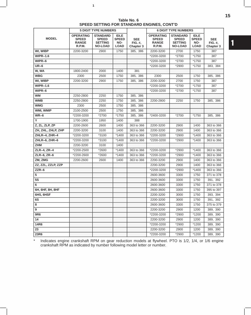
Table No. 6SPEED SETTING FOR STANDARD ENGINES
5 DIGIT TYPE NUMBERS 6 DIGIT TYPE NUMBERS
MODELOPERATING
SPEEDRANGER.P.M.
STANDARDSPEED
SETTINGNO-LOAD
IDLESPEED
NO-LOAD
SEEFIG. #,
Chapter 3
OPERATINGSPEEDRANGER.P.M.
STANDARDSPEED
SETTINGNO-LOAD
IDLESPEED
NO-LOAD
SEEFIG. #,
Chapter 3
A 2200-3200 2400 1400 358 2200-3200 2900 1400 359
AGR−4 *2000-2400 *2200 *1400 358
AH, AHL, AHLP, AHP 2200-3200 2900 1400 358
AHM, AHMT 2200-3200 2900 1400 358
AHR−4 *2200-3200 *3000 *1400 358
AHR−6 *2200-3200 *2900 *1400 358
AL, ALP, AP 2200-2400 2400 1400 358 2200-3200 2900 1400 359
ALR−4, AR−4 *2000-2400 *2400 *1400 358
ALR−6, AR−6 *2000-2400 *2400 *1400 358 *2200-3200 *2900 *1400 359
AM, AMT 2000-2400 2400 1400 358
B, BP 2300-2700 2700 1400 363 to 366 2200-3200 2900 1400 363 to 366
BH, BHL, BHLP, BHP 2200-3200 2900 1400 363 to 366 2200-3200 2900 1400 363 to 366
BHM 2200-3200 2900 1400 363 to 366
BHLR−4, BHR−4 *3000-3600 *3000 *1400 363 to 366
BHLR−6, BHR−6 *3000-3600 *2900 *1400 363 to 366
BL, BLP 2300-2700 2700 1400 363 to 366 2200-3200 2900 1400 363 to 366
BLR−4, BR−4 *2300-2700 *2700 *1400 363 to 366 *2200-3200 *2900 *1400 363 to 366
BLR−6, BR−6 *2300-2700 *2700 *1400 363 to 366 *2200-3200 *2900 *1400 363 to 366
BM BMG 2300-2700 2700 1400 363 to 366 2200-3200 2900 1400 363 to 366
FH 1750-1800 1950 1400 367
14
1
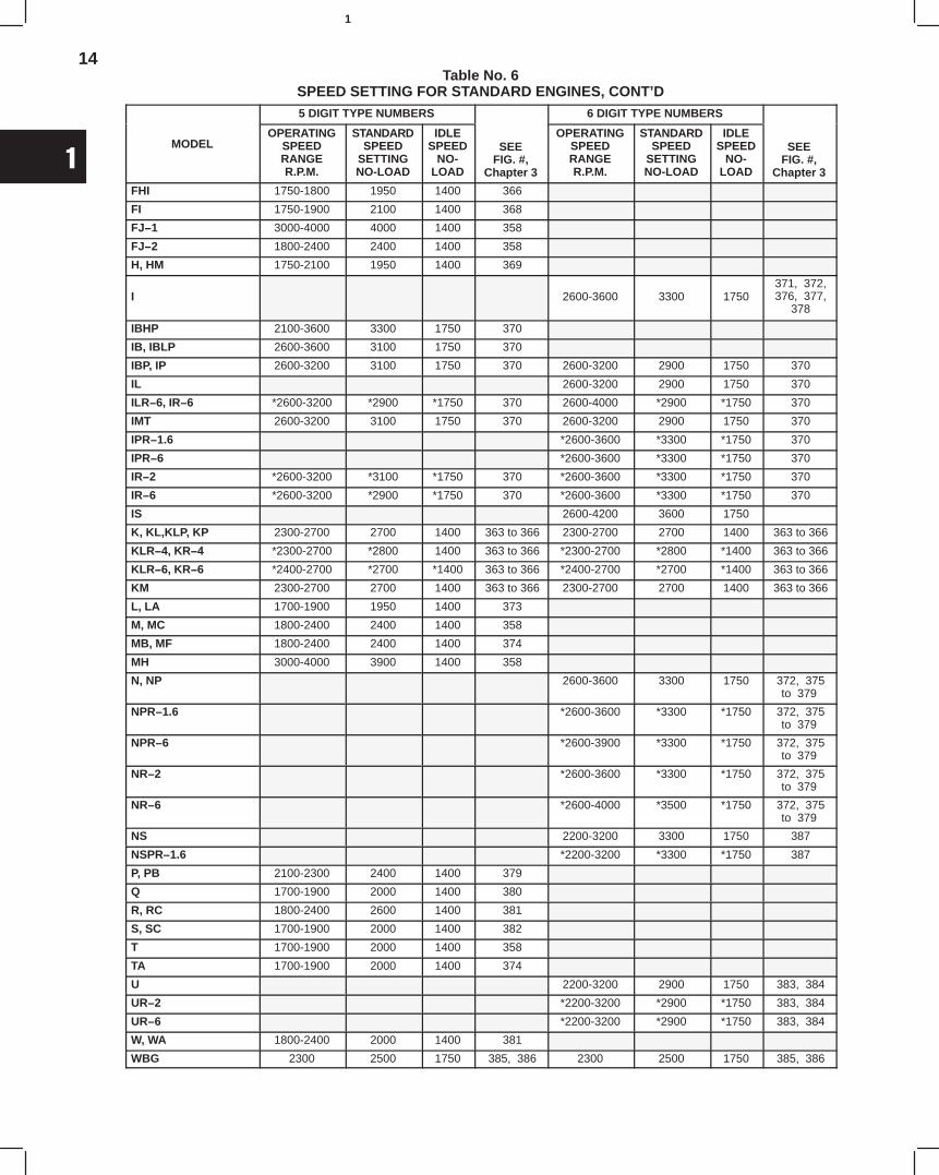
Table No. 6SPEED SETTING FOR STANDARD ENGINES, CONT’D5 DIGIT TYPE NUMBERS 6 DIGIT TYPE NUMBERS
MODELOPERATING
SPEEDRANGER.P.M.
STANDARDSPEED
SETTINGNO-LOAD
IDLESPEED
NO-LOAD
SEEFIG. #,
Chapter 3
OPERATINGSPEEDRANGER.P.M.
STANDARDSPEED
SETTINGNO-LOAD
IDLESPEED
NO-LOAD
SEEFIG. #,
Chapter 3
FHI 1750-1800 1950 1400 366
FI 1750-1900 2100 1400 368
FJ−1 3000-4000 4000 1400 358
FJ−2 1800-2400 2400 1400 358
H, HM 1750-2100 1950 1400 369
I 2600-3600 3300 1750 371, 372, 376, 377,
378
IBHP 2100-3600 3300 1750 370
IB, IBLP 2600-3600 3100 1750 370
IBP, IP 2600-3200 3100 1750 370 2600-3200 2900 1750 370
IL 2600-3200 2900 1750 370
ILR−6, IR−6 *2600-3200 *2900 *1750 370 2600-4000 *2900 *1750 370
IMT 2600-3200 3100 1750 370 2600-3200 2900 1750 370
IPR−1.6 *2600-3600 *3300 *1750 370
IPR−6 *2600-3600 *3300 *1750 370
IR−2 *2600-3200 *3100 *1750 370 *2600-3600 *3300 *1750 370
IR−6 *2600-3200 *2900 *1750 370 *2600-3600 *3300 *1750 370
IS 2600-4200 3600 1750
K, KL,KLP, KP 2300-2700 2700 1400 363 to 366 2300-2700 2700 1400 363 to 366
KLR−4, KR−4 *2300-2700 *2800 1400 363 to 366 *2300-2700 *2800 *1400 363 to 366
KLR−6, KR−6 *2400-2700 *2700 *1400 363 to 366 *2400-2700 *2700 *1400 363 to 366
KM 2300-2700 2700 1400 363 to 366 2300-2700 2700 1400 363 to 366
L, LA 1700-1900 1950 1400 373
M, MC 1800-2400 2400 1400 358
MB, MF 1800-2400 2400 1400 374
MH 3000-4000 3900 1400 358
N, NP 2600-3600 3300 1750 372, 375to 379
NPR−1.6 *2600-3600 *3300 *1750 372, 375to 379
NPR−6 *2600-3900 *3300 *1750 372, 375to 379
NR−2 *2600-3600 *3300 *1750 372, 375to 379
NR−6 *2600-4000 *3500 *1750 372, 375to 379
NS 2200-3200 3300 1750 387
NSPR−1.6 *2200-3200 *3300 *1750 387
P, PB 2100-2300 2400 1400 379
Q 1700-1900 2000 1400 380
R, RC 1800-2400 2600 1400 381
S, SC 1700-1900 2000 1400 382
T 1700-1900 2000 1400 358
TA 1700-1900 2000 1400 374
U 2200-3200 2900 1750 383, 384
UR−2 *2200-3200 *2900 *1750 383, 384
UR−6 *2200-3200 *2900 *1750 383, 384
W, WA 1800-2400 2000 1400 381
WBG 2300 2500 1750 385, 386 2300 2500 1750 385, 386
15
1
Table No. 6SPEED SETTING FOR STANDARD ENGINES, CONT’D5 DIGIT TYPE NUMBERS 6 DIGIT TYPE NUMBERS
MODELOPERATING
SPEEDRANGER.P.M.
STANDARDSPEED
SETTINGNO-LOAD
IDLESPEED
NO-LOAD
SEEFIG. #,
Chapter 3
OPERATINGSPEEDRANGER.P.M.
STANDARDSPEED
SETTINGNO-LOAD
IDLESPEED
NO-LOAD
SEEFIG. #,
Chapter 3
WI, WIBP 2200-3200 2900 1750 385, 386 2200-3200 2700 1750 387
WIPR−1.6 *2200-3200 *2700 *1750 387
WIPR−6 *2200-3200 *2700 *1750 387
UR−6 *2200-3200 *2900 *1750 383, 384
W, WA 1800-2400 2000 1400 381
WBG 2300 2500 1750 385, 386 2300 2500 1750 385, 386
WI, WIBP 2200-3200 2900 1750 385, 386 2200-3200 2700 1750 387
WIPR−1.6 *2200-3200 *2700 *1750 387
WIPR−6 *2200-3200 *2700 *1750 387
WM 2250-2800 2250 1750 385, 386
WMB 2250-2800 2250 1750 385, 386 2200-2800 2250 1750 385, 386
WMG 2300 2500 1750 385, 386
WMI, WMIP 2100-2500 2500 1750 385, 386
WR−6 *2200-3200 *2700 *1750 385, 386 *2400-3200 *2700 *1750 385, 386
Y 1700-1900 1950 1400 388
Z, ZL, ZLP, ZP 2200-2600 2600 1400 363 to 366 2200-3200 2900 1400 363 to 366
ZH, ZHL, ZHLP, ZHP 2200-3200 3100 1400 363 to 366 2200-3200 2900 1400 363 to 366
ZHLR−4, ZHR−4 *2200-3200 *3100 *1400 363 to 366 *2200-3200 *2900 *1400 363 to 366
ZHLR−6, ZHR−6 *2200-3200 *3100 *1400 363 to 366 *2200-3200 *2900 *1400 363 to 366
ZHM 2200-3200 3100 1400
ZLR−4, ZR−4 *2200-2500 *2600 *1400 363 to 366 *2200-3200 *2900 *1400 363 to 366
ZLR−6, ZR−6 *2200-2600 *2600 *1400 363 to 366 *2200-3200 *2900 *1400 363 to 366
ZM, ZMG 2200-2600 2600 1400 363 to 366 2200-3200 2900 1400 363 to 366
ZZ, ZZL, ZZLP, ZZP 2200-3200 2900 1400 363 to 366
ZZR−6 *2200-3200 *2900 *1400 363 to 366
5 2600-3600 3300 1750 371 to 378
5S 2600-3600 3300 1750 391, 392
6 2600-3600 3300 1750 371 to 378
6H, 6HF, 8H, 8HF 2600-3600 3300 1750 395 to 397
6HS, 6HSF 2200-3200 3000 1750 393, 394
6S 2200-3200 3000 1750 391, 392
8 2600-3600 3300 1750 375 to 379
9 2200-3200 2900 1200 389, 390
9R6 *2200-3200 *2900 *1200 389, 390
14 2200-3200 2900 1200 389, 390
14R6 *2200-3200 *2900 *1200 389, 390
23 2200-3200 2900 1200 389, 390
23R6 *2200-3200 *2900 *1200 389, 390
* Indicates engine crankshaft RPM on gear reduction models at flywheel. PTO is 1/2, 1/4, or 1/6 enginecrankshaft RPM as indicated by number following model letter or number.

1
2
Section 2IGNITION
Briggs & Stratton ignition systems may be divided into eight (8) groups which are similar in many ways:
STYLE 1 Used on Cast Iron Models A, B, H, K, Y, Z, ZZTo check spark, see Page 2.
STYLE 2 Used on Cast Iron Models FH, FI, FJ, L, M, P, PB, Q, R, S, T, WTo check spark, see Page 2.
STYLE 3 Used on Cast Iron Models I, N, NS, U, WI, WM, WMB, 5, 6, 8To check spark, see Page 2.
STYLE 4 MAGNEMATIC Used on Cast Iron Models 9, 14, 19, 23, 23A, 191400, 231400To check spark, see Page 3.
STYLE 5 Used on Cast Iron Model Series 23CTo check spark, see Page 2.
STYLE 6 Used on Cast Iron Model Series 19D, 23D, 193400, 200400, 233400, 243400,300000, 320000To check spark, see Page 2.
STYLE 7 Used on Aluminum Model Series 6B, 8B, 60000, through 260000To check spark, see Page 2.
STYLE 8 MAGNEVAC Used on Aluminum Model Series 253400To check spark, see Page 2.
Current is produced by an armature (coil), condenser, breaker points, and rotating magnets and is conducted into thefiring chamber through the ignition cable and spark plug. It is important that all parts be in good condition, correctlyadjusted and properly connected to assure a good spark.
SPARK PLUGS – ALL MODELS
SPARK PLUG, Cast Iron Model Series Athrough ZZ & 5 through 23D
The plugs recommended for Briggs & Stratton enginesare listed in Table No. 4, Section 1, Page 9 and shouldbe installed unless special engine use requires a plugof different heat range.
Check Spark Plug, Cast Iron ModelSeries A through ZZ & 5 through 23DClean spark plug and set gap to .025, (0.64 mm)Fig. 2. If electrodes are burned away, or if porcelain iscracked, replace with a new plug of the proper heatrange. Before assembling the spark plug, place a littlegraphite grease on the threads to prevent sticking.
2
2
IGNITION (cont’d)
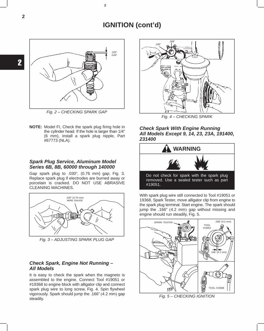
Fig. 2 – CHECKING SPARK GAP
.025”GAP
NOTE: Model FI, Check the spark plug firing hole inthe cylinder head. If the hole is larger than 1/4”(6 mm), install a spark plug nipple, Part#67773 (NLA).
Spark Plug Service, Aluminum ModelSeries 6B, 8B, 60000 through 140000Gap spark plug to .030”, (0.76 mm) gap, Fig. 3.Replace spark plug if electrodes are burned away orporcelain is cracked. DO NOT USE ABRASIVECLEANING MACHINES.
.030” (0.76 mm)WIRE GAUGE
Fig. 3 – ADJUSTING SPARK PLUG GAP
Check Spark, Engine Not Running – All ModelsIt is easy to check the spark when the magneto isassembled to the engine. Connect Tool #19051 or#19368 to engine block with alligator clip and connectspark plug wire to long screw, Fig. 4. Spin flywheelvigorously. Spark should jump the .166”4.2 mm gapsteadily.
Fig. 4 – CHECKING SPARK
.008”.166”
Check Spark With Engine RunningAll Models Except 9, 14, 23, 23A, 191400,231400
WARNING
Do not check for spark with the spark plugremoved. Use a sealed tester such as part#19051.
With spark plug wire still connected to Tool #19051 or19368, Spark Tester, move alligator clip from engine tothe spark plug terminal. Start engine. The spark shouldjump the .166” 4.2 mm gap without missing andengine should run steadily, Fig. 5.
Fig. 5 – CHECKING IGNITION
SPARK TESTER .008” (0.2 mm)
.166” (4.2 mm)
TOOL#19051
TOOL #19368
3
2
IGNITION (cont’d)
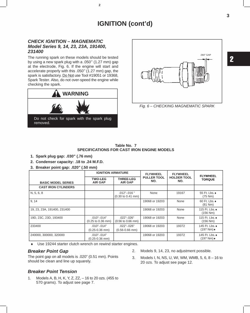
CHECK IGNITION – MAGNEMATICModel Series 9, 14, 23, 23A, 191400,231400The running spark on these models should be testedby using a new spark plug with a .050 (1.27 mm) gapat the electrode, Fig. 6. If the engine will start andaccelerate properly with this .050(1.27 mm) gap, thespark is satisfactory. Do Not use Tool #19051 or 19368,Spark Tester. Also, do not over-speed the engine whilechecking the spark.
WARNING
Do not check for spark with the spark plugremoved.
Fig. 6 – CHECKING MAGNEMATIC SPARK
.060” GAP
Table No. 7SPECIFICATIONS FOR CAST IRON ENGINE MODELS
1. Spark plug gap: .030” (.76mm)2. Condenser capacity: .18 to .24 M.F.D.3. Breaker point gap: .020”(.50 mm)
IGNITION ARMATURE FLYWHEELPULLER TOOL
FLYWHEELHOLDER TOOL FLYWHEEL
TWO-LEG THREE-LEG PULLER TOOLNO
HOLDER TOOLNO
FLYWHEELTORQUE
BASIC MODEL SERIESTWO LEGAIR GAP
THREE LEGAIR GAP NO. NO. TORQUE
CAST IRON CYLINDERS
N, 5, 6, 8 .012”-.016 ”(0.30 to 0.41 mm)
None 19167 55 Ft. Lbs.♦(75 Nm)
9, 14 19068 or 19203 None 60 Ft. Lbs.♦(81 Nm)
19, 23, 23A, 191400, 231400 19068 or 19203 None 115 Ft. Lbs.♦(156 Nm)
19D, 23C, 23D, 193400 .010”-.014”(0.25 to 0.36 mm)
.022”-.026”(0.56 to 0.66 mm)
19068 or 19203 None 115 Ft. Lbs.♦(156 Nm)
233400 .010”-.014”(0.25-0.36 mm)
.022”-.026”(0.56-0.66 mm)
19068 or 19203 19372 145 Ft. Lbs.♦(197 Nm)♦
240000, 300000, 320000 .010”-.014”(0.25-0.36 mm)
19068 or 19203 19372 145 Ft. Lbs.♦(197 Nm)♦
♦ Use 19244 starter clutch wrench on rewind starter engines.
Breaker Point GapThe point gap on all models is .020” (0.51 mm) Pointsshould be clean and line up squarely.
Breaker Point Tension1. Models A, B, H, K, Y, Z, ZZ, – 16 to 20 ozs. (455 to
570 grams). To adjust see page 7.
2. Models 9, 14, 23, no adjustment possible.
3. Models I, N, NS, U, WI, WM, WMB, 5, 6, 8 – 16 to20 ozs. To adjust see page 12.
4
2
IGNITION (cont’d)
CONDENSERThe capacity of all condensers is .16 to .24 MFD.
BLOWER HOUSING
REMOVE BLOWER HOUSINGThe blower housing on most models are easilyremoved, but on Models 9, 14, 23 and rope starterModels A, B, K, Z, ZZ, the rope starter pulley must beremoved before the the blower housing as follows:
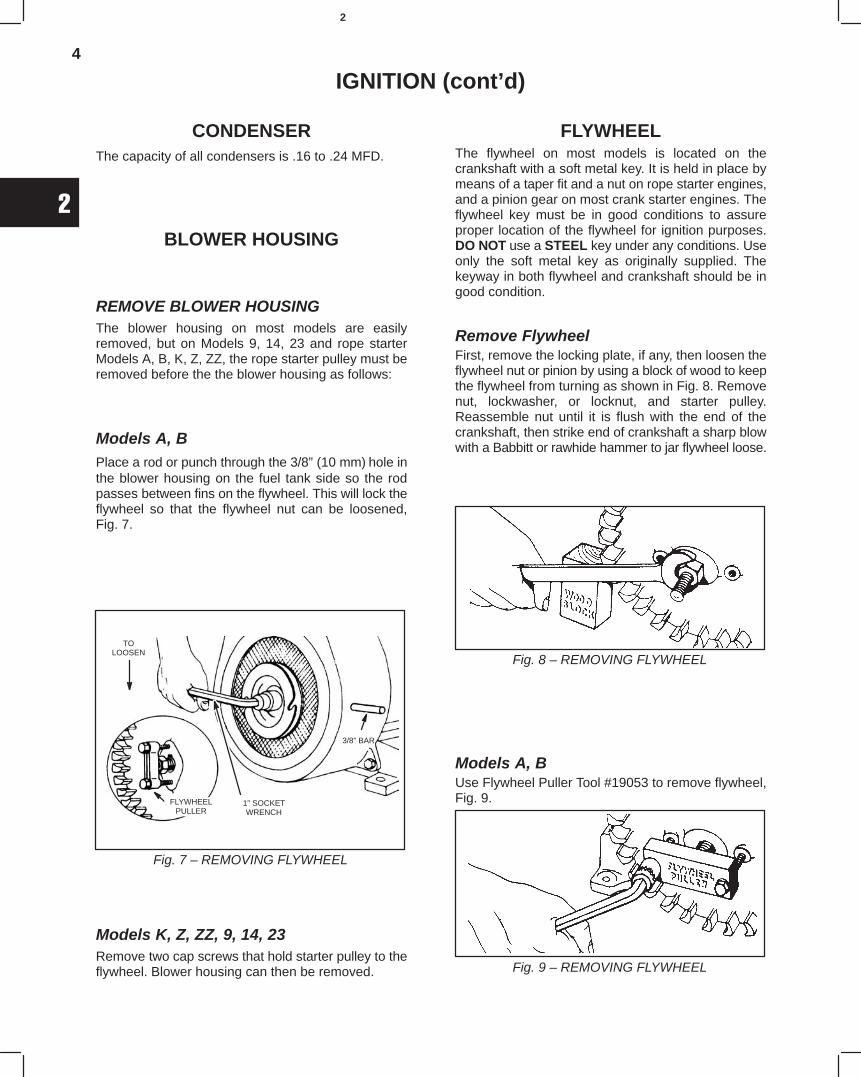
Models A, BPlace a rod or punch through the 3/8” (10 mm)hole inthe blower housing on the fuel tank side so the rodpasses between fins on the flywheel. This will lock theflywheel so that the flywheel nut can be loosened,Fig. 7.
Fig. 7 – REMOVING FLYWHEEL
TOLOOSEN
FLYWHEELPULLER
1” SOCKETWRENCH
3/8” BAR
Models K, Z, ZZ, 9, 14, 23Remove two cap screws that hold starter pulley to theflywheel. Blower housing can then be removed.
FLYWHEELThe flywheel on most models is located on thecrankshaft with a soft metal key. It is held in place bymeans of a taper fit and a nut on rope starter engines,and a pinion gear on most crank starter engines. Theflywheel key must be in good conditions to assureproper location of the flywheel for ignition purposes.DO NOT use a STEEL key under any conditions. Useonly the soft metal key as originally supplied. Thekeyway in both flywheel and crankshaft should be ingood condition.
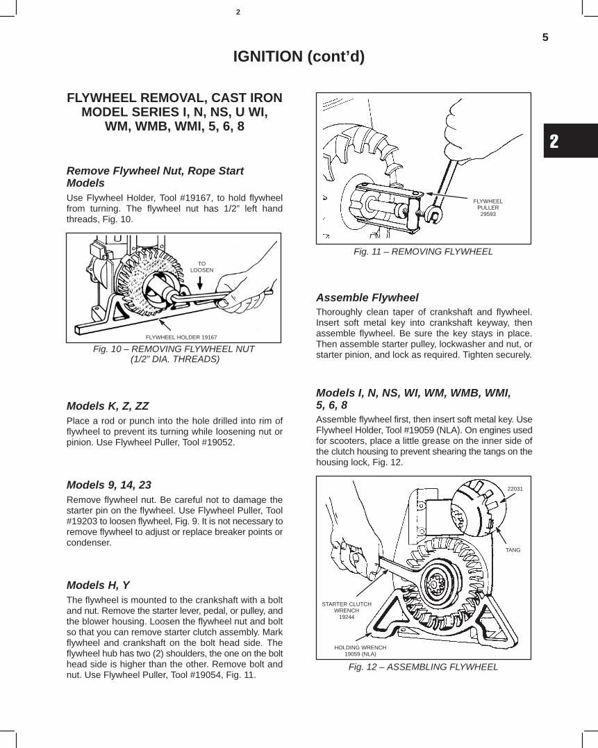
Remove FlywheelFirst, remove the locking plate, if any, then loosen theflywheel nut or pinion by using a block of wood to keepthe flywheel from turning as shown in Fig. 8. Removenut, lockwasher, or locknut, and starter pulley.Reassemble nut until it is flush with the end of thecrankshaft, then strike end of crankshaft a sharp blowwith a Babbitt or rawhide hammer to jar flywheel loose.
Fig. 8 – REMOVING FLYWHEEL
Models A, BUse Flywheel Puller Tool #19053 to remove flywheel,Fig. 9.
Fig. 9 – REMOVING FLYWHEEL
5
2
IGNITION (cont’d)
FLYWHEEL REMOVAL, CAST IRONMODEL SERIES I, N, NS, U WI,
WM, WMB, WMI, 5, 6, 8
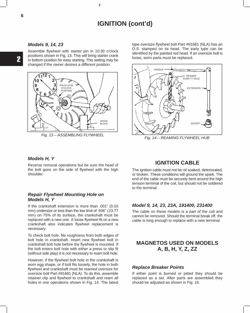
Remove Flywheel Nut, Rope StartModelsUse Flywheel Holder, Tool #19167, to hold flywheelfrom turning. The flywheel nut has 1/2” left handthreads, Fig. 10.
Fig. 10 – REMOVING FLYWHEEL NUT (1/2” DIA. THREADS)
TOLOOSEN
FLYWHEEL HOLDER 19167
Models K, Z, ZZPlace a rod or punch into the hole drilled into rim offlywheel to prevent its turning while loosening nut orpinion. Use Flywheel Puller, Tool #19052.
Models 9, 14, 23Remove flywheel nut. Be careful not to damage thestarter pin on the flywheel. Use Flywheel Puller, Tool#19203 to loosen flywheel, Fig. 9. It is not necessary toremove flywheel to adjust or replace breaker points orcondenser.
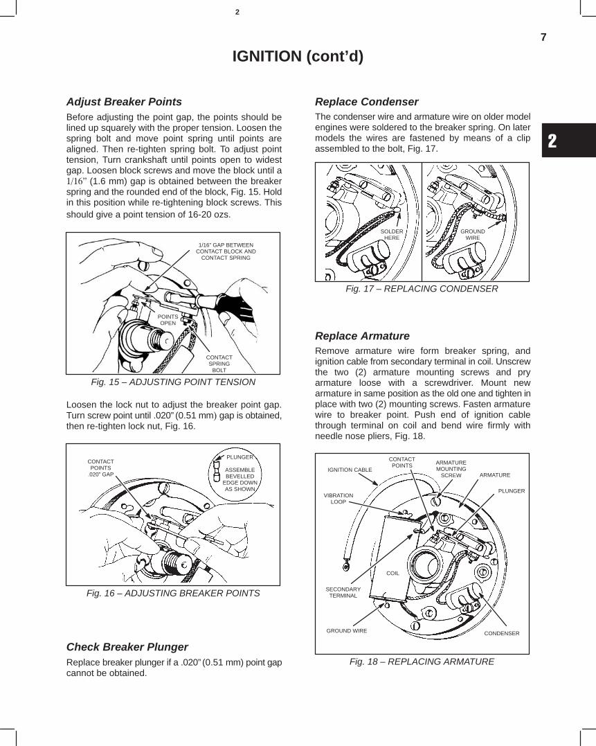
Models H, YThe flywheel is mounted to the crankshaft with a boltand nut. Remove the starter lever, pedal, or pulley, andthe blower housing. Loosen the flywheel nut and boltso that you can remove starter clutch assembly. Markflywheel and crankshaft on the bolt head side. Theflywheel hub has two (2) shoulders, the one on the bolthead side is higher than the other. Remove bolt andnut. Use Flywheel Puller, Tool #19054, Fig. 11.
Fig. 11 – REMOVING FLYWHEEL
FLYWHEELPULLER
29593
Assemble FlywheelThoroughly clean taper of crankshaft and flywheel.Insert soft metal key into crankshaft keyway, thenassemble flywheel. Be sure the key stays in place.Then assemble starter pulley, lockwasher and nut, orstarter pinion, and lock as required. Tighten securely.
Models I, N, NS, WI, WM, WMB, WMI, 5, 6, 8Assemble flywheel first, then insert soft metal key. UseFlywheel Holder, Tool #19059 (NLA). On engines usedfor scooters, place a little grease on the inner side ofthe clutch housing to prevent shearing the tangs on thehousing lock, Fig. 12.
Fig. 12 – ASSEMBLING FLYWHEEL
STARTER CLUTCHWRENCH
19244
HOLDING WRENCH19059 (NLA)
22031
TANG
6
2
IGNITION (cont’d)
Models 9, 14, 23Assemble flywheel with starter pin in 10:30 o’clockpositions shown in Fig. 13. This will bring starter crankin bottom position for easy starting. This setting may bechanged if the owner desires a different position.
Fig. 13 – ASSEMBLING FLYWHEEL
WOODBLOCK
PIN IN 10:30O’CLOCKPOSITION
Models H, YReverse removal operations but be sure the head ofthe bolt goes on the side of flywheel with the highshoulder.
Repair Flywheel Mounting Hole onModels H, YIf the crankshaft extension is more than .001” (0.03mm) undersize or less than the low limit of .936 23.77mm on 75% of its surface, the crankshaft must bereplaced with a new one. A loose flywheel fit on a newcrankshaft also indicates flywheel replacement isnecessary.
To check bolt hole, file roughness from both edges ofbolt hole in crankshaft. Insert new flywheel bolt incrankshaft bolt hole before the flywheel is mounted. Ifthe bolt enters bolt hole with either a press or slip fit(without side play) it is not necessary to ream bolt hole.
However, if the flywheel bolt hole in the crankshaft isworn egg shape, or if bolt fits loosely, the hole in bothflywheel and crankshaft must be reamed oversize foroversize bolt Part #91681 (NLA). To do this, assembleretainer clip and flywheel to crankshaft and ream allholes in one operations shown in Fig. 14. The latest
type oversize flywheel bolt Part #91681 (NLA) has anO.S. stamped on its head. The early type can beidentified by the painted red head. If an oversize bolt isloose, worn parts must be replaced.
Fig. 14 – REAMING FLYWHEEL HUB
HANDLE
REAMER61260-T7 (NLA)
EXTENSION
SOCKET
IGNITION CABLEThe ignition cable must not be oil soaked, deteriorated,or broken. These conditions will ground the spark. Theend of the cable must be securely bent around the hightension terminal of the coil, but should not be solderedto the terminal.
Model 9, 14, 23, 23A, 191400, 231400The cable on these models is a part of the coil andcannot be removed. Should the terminal break off, thecable is long enough to replace with a new terminal.
MAGNETOS USED ON MODELSA, B, H, Y, Z, ZZ
Replace Breaker PointsIf either point is burned or pitted they should bereplaced as a set. After parts are assembled theyshould be adjusted as shown in Fig. 16.
7
2
IGNITION (cont’d)
Adjust Breaker PointsBefore adjusting the point gap, the points should belined up squarely with the proper tension. Loosen thespring bolt and move point spring until points arealigned. Then re-tighten spring bolt. To adjust pointtension, Turn crankshaft until points open to widestgap. Loosen block screws and move the block until a(1.6 mm) gap is obtained between the breakerspring and the rounded end of the block, Fig. 15. Holdin this position while re-tightening block screws. Thisshould give a point tension of 16-20 ozs.
Fig. 15 – ADJUSTING POINT TENSION
1/16” GAP BETWEENCONTACT BLOCK AND
CONTACT SPRING
POINTSOPEN
CONTACTSPRING
BOLT
Loosen the lock nut to adjust the breaker point gap.Turn screw point until .020”(0.51 mm gap is obtained,then re-tighten lock nut, Fig. 16.
Fig. 16 – ADJUSTING BREAKER POINTS
CONTACTPOINTS
.020” GAP
PLUNGER
ASSEMBLEBEVELLED
EDGE DOWNAS SHOWN
Check Breaker PlungerReplace breaker plunger if a .020”(0.51 mm) point gapcannot be obtained.
Replace CondenserThe condenser wire and armature wire on older modelengines were soldered to the breaker spring. On latermodels the wires are fastened by means of a clipassembled to the bolt, Fig. 17.
Fig. 17 – REPLACING CONDENSER
SOLDERHERE
GROUNDWIRE
Replace ArmatureRemove armature wire form breaker spring, andignition cable from secondary terminal in coil. Unscrewthe two (2) armature mounting screws and pryarmature loose with a screwdriver. Mount newarmature in same position as the old one and tighten inplace with two (2) mounting screws. Fasten armaturewire to breaker point. Push end of ignition cablethrough terminal on coil and bend wire firmly withneedle nose pliers, Fig. 18.
IGNITION CABLEARMATUREMOUNTING
SCREW ARMATURE
PLUNGER
CONDENSERGROUND WIRE
SECONDARYTERMINAL
VIBRATIONLOOP
COIL
CONTACTPOINTS
Fig. 18 – REPLACING ARMATURE
8
2
IGNITION (cont’d)
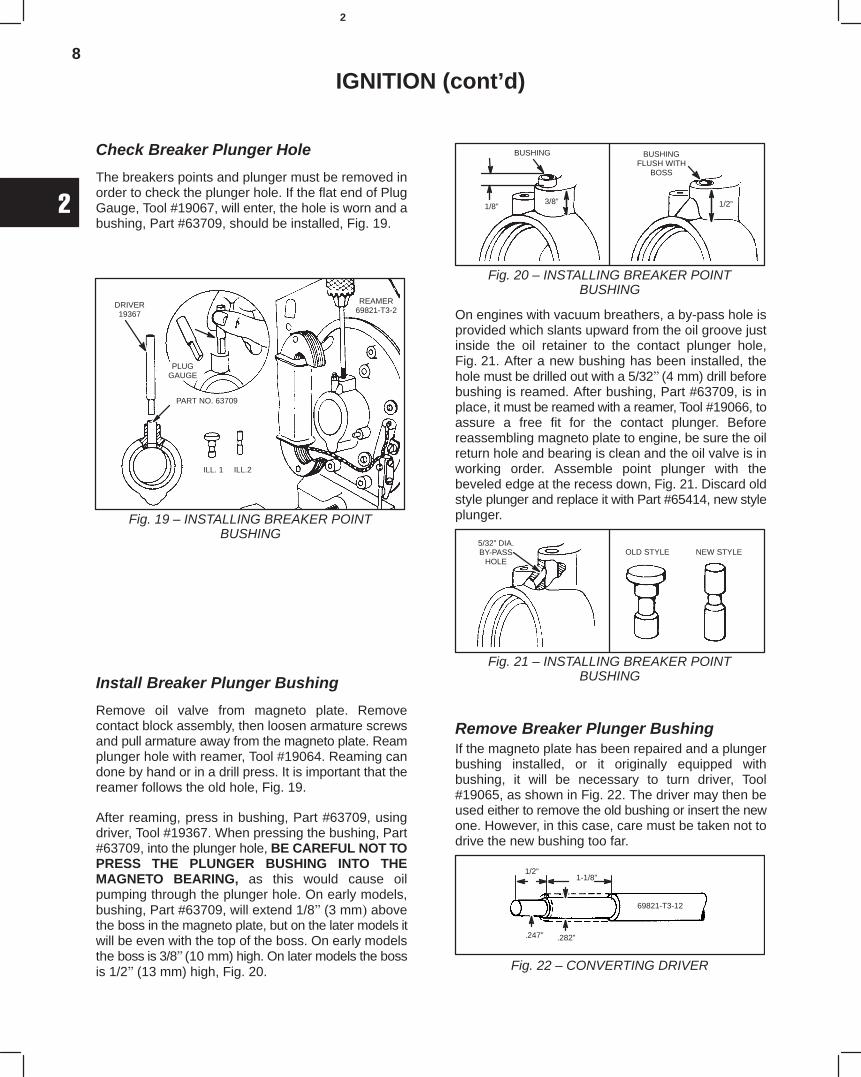
Check Breaker Plunger Hole
The breakers points and plunger must be removed inorder to check the plunger hole. If the flat end of PlugGauge, Tool #19067, will enter, the hole is worn and abushing, Part #63709, should be installed, Fig. 19.
Fig. 19 – INSTALLING BREAKER POINTBUSHING
DRIVER19367
PART NO. 63709
ILL. 1 ILL.2
REAMER69821-T3-2
PLUGGAUGE
Install Breaker Plunger Bushing
Remove oil valve from magneto plate. Removecontact block assembly, then loosen armature screwsand pull armature away from the magneto plate. Reamplunger hole with reamer, Tool #19064. Reaming candone by hand or in a drill press. It is important that thereamer follows the old hole, Fig. 19.
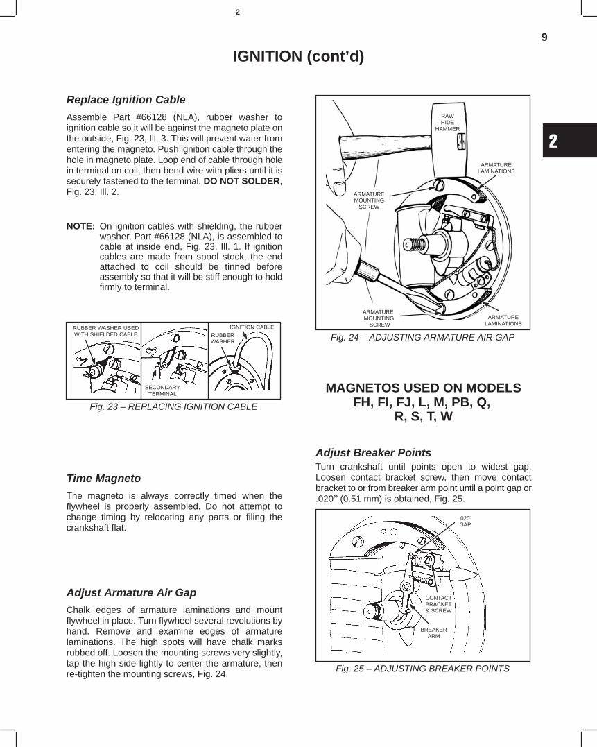
After reaming, press in bushing, Part #63709, usingdriver, Tool #19367. When pressing the bushing, Part#63709, into the plunger hole, BE CAREFUL NOT TOPRESS THE PLUNGER BUSHING INTO THEMAGNETO BEARING, as this would cause oilpumping through the plunger hole. On early models,bushing, Part #63709, will extend 1/8(3 mm abovethe boss in the magneto plate, but on the later models itwill be even with the top of the boss. On early modelsthe boss is 3/8(10 mm) high. On later models the bossis 1/2(13 mm) high, Fig. 20.
Fig. 20 – INSTALLING BREAKER POINTBUSHING
1/8”3/8”
BUSHING BUSHINGFLUSH WITH
BOSS
1/2”
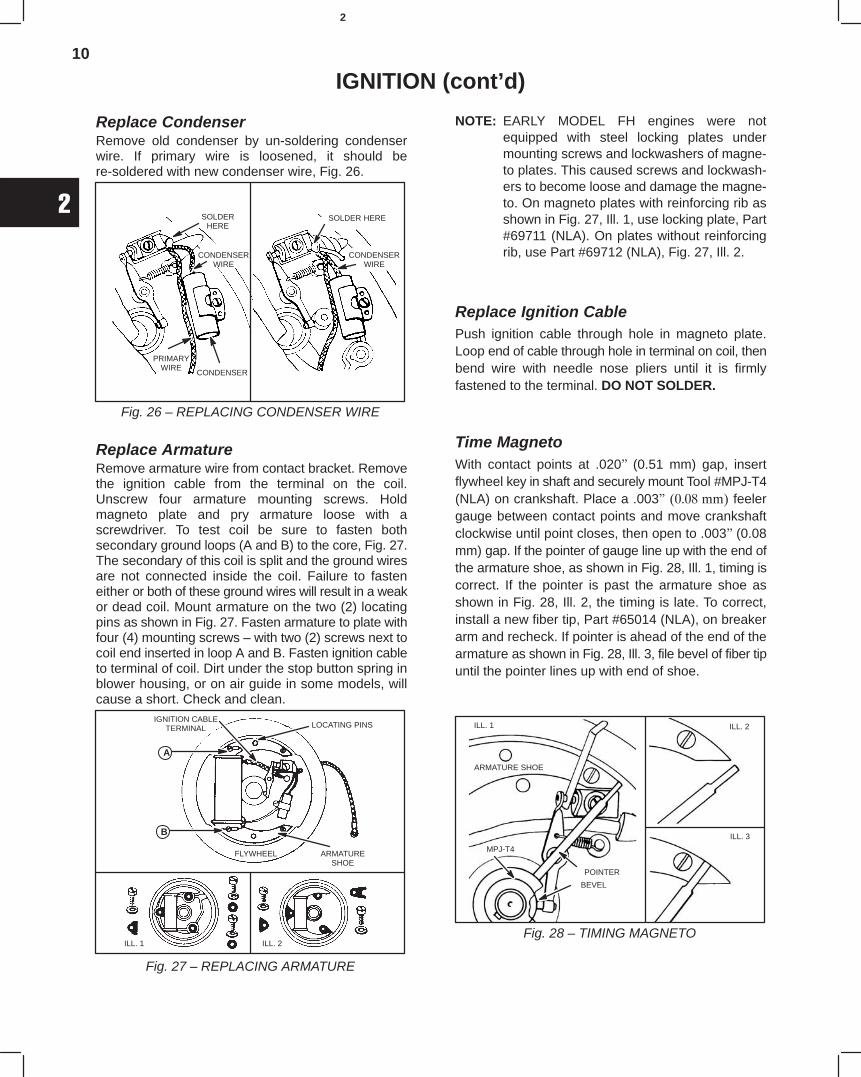
On engines with vacuum breathers, a by-pass hole isprovided which slants upward from the oil groove justinside the oil retainer to the contact plunger hole,Fig. 21. After a new bushing has been installed, thehole must be drilled out with a 5/32(4 mm) drill beforebushing is reamed. After bushing, Part #63709, is inplace, it must be reamed with a reamer, Tool #19066, toassure a free fit for the contact plunger. Beforereassembling magneto plate to engine, be sure the oilreturn hole and bearing is clean and the oil valve is inworking order. Assemble point plunger with thebeveled edge at the recess down, Fig. 21. Discard oldstyle plunger and replace it with Part #65414, new styleplunger.
Fig. 21 – INSTALLING BREAKER POINTBUSHING
5/32” DIA.BY-PASS
HOLEOLD STYLE NEW STYLE
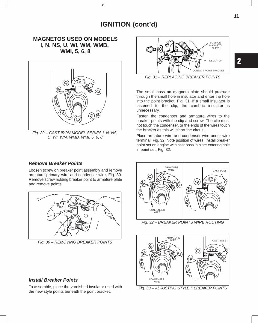
Remove Breaker Plunger BushingIf the magneto plate has been repaired and a plungerbushing installed, or it originally equipped withbushing, it will be necessary to turn driver, Tool#19065, as shown in Fig. 22. The driver may then beused either to remove the old bushing or insert the newone. However, in this case, care must be taken not todrive the new bushing too far.
Fig. 22 – CONVERTING DRIVER
1/2”1-1/8”
.282”.247”
69821-T3-12
9
2
IGNITION (cont’d)
Replace Ignition Cable
Assemble Part #66128 (NLA), rubber washer toignition cable so it will be against the magneto plate onthe outside, Fig. 23, Ill. 3. This will prevent water fromentering the magneto. Push ignition cable through thehole in magneto plate. Loop end of cable through holein terminal on coil, then bend wire with pliers until it issecurely fastened to the terminal. DO NOT SOLDER,Fig. 23, Ill. 2.
NOTE: On ignition cables with shielding, the rubberwasher, Part #66128 (NLA), is assembled tocable at inside end, Fig. 23, Ill. 1. If ignitioncables are made from spool stock, the endattached to coil should be tinned beforeassembly so that it will be stiff enough to holdfirmly to terminal.
Fig. 23 – REPLACING IGNITION CABLE
RUBBER WASHER USEDWITH SHIELDED CABLE
SECONDARYTERMINAL
IGNITION CABLERUBBERWASHER
Time Magneto
The magneto is always correctly timed when theflywheel is properly assembled. Do not attempt tochange timing by relocating any parts or filing thecrankshaft flat.
Adjust Armature Air Gap
Chalk edges of armature laminations and mountflywheel in place. Turn flywheel several revolutions byhand. Remove and examine edges of armaturelaminations. The high spots will have chalk marksrubbed off. Loosen the mounting screws very slightly,tap the high side lightly to center the armature, thenre-tighten the mounting screws, Fig. 24.
Fig. 24 – ADJUSTING ARMATURE AIR GAP
RAWHIDE
HAMMER
ARMATURELAMINATIONS
ARMATUREMOUNTING
SCREW
ARMATURE MOUNTING
SCREWARMATURE
LAMINATIONS
MAGNETOS USED ON MODELSFH, FI, FJ, L, M, PB, Q,
R, S, T, W
Adjust Breaker PointsTurn crankshaft until points open to widest gap.Loosen contact bracket screw, then move contactbracket to or from breaker arm point until a point gap or.020(0.51 mm) is obtained, Fig. 25.
Fig. 25 – ADJUSTING BREAKER POINTS
.020”GAP
CONTACTBRACKET& SCREW
BREAKERARM
10
2
IGNITION (cont’d)
Replace CondenserRemove old condenser by un-soldering condenserwire. If primary wire is loosened, it should bere-soldered with new condenser wire, Fig. 26.
Fig. 26 – REPLACING CONDENSER WIRE
SOLDERHERE
CONDENSERWIRE
CONDENSER
PRIMARYWIRE
SOLDER HERE
CONDENSERWIRE
Replace ArmatureRemove armature wire from contact bracket. Removethe ignition cable from the terminal on the coil.Unscrew four armature mounting screws. Holdmagneto plate and pry armature loose with ascrewdriver. To test coil be sure to fasten bothsecondary ground loops (A and B) to the core, Fig. 27.The secondary of this coil is split and the ground wiresare not connected inside the coil. Failure to fasteneither or both of these ground wires will result in a weakor dead coil. Mount armature on the two (2) locatingpins as shown in Fig. 27. Fasten armature to plate withfour (4) mounting screws – with two (2) screws next tocoil end inserted in loop A and B. Fasten ignition cableto terminal of coil. Dirt under the stop button spring inblower housing, or on air guide in some models, willcause a short. Check and clean.
Fig. 27 – REPLACING ARMATURE
LOCATING PINSIGNITION CABLE
TERMINAL
FLYWHEEL ARMATURESHOE
ILL. 1 ILL. 2
A
B
NOTE: EARLY MODEL FH engines were notequipped with steel locking plates undermounting screws and lockwashers of magne-to plates. This caused screws and lockwash-ers to become loose and damage the magne-to. On magneto plates with reinforcing rib asshown in Fig. 27, Ill. 1, use locking plate, Part#69711 (NLA). On plates without reinforcingrib, use Part #69712 (NLA), Fig. 27, Ill. 2.
Replace Ignition CablePush ignition cable through hole in magneto plate.Loop end of cable through hole in terminal on coil, thenbend wire with needle nose pliers until it is firmlyfastened to the terminal. DO NOT SOLDER.
Time MagnetoWith contact points at .020 (0.51 mm) gap, insertflywheel key in shaft and securely mount Tool #MPJ-T4(NLA) on crankshaft. Place a .003 feelergauge between contact points and move crankshaftclockwise until point closes, then open to .003(0.08mm) gap. If the pointer of gauge line up with the end ofthe armature shoe, as shown in Fig. 28, Ill. 1, timing iscorrect. If the pointer is past the armature shoe asshown in Fig. 28, Ill. 2, the timing is late. To correct,install a new fiber tip, Part #65014 (NLA), on breakerarm and recheck. If pointer is ahead of the end of thearmature as shown in Fig. 28, Ill. 3, file bevel of fiber tipuntil the pointer lines up with end of shoe.
Fig. 28 – TIMING MAGNETO
ARMATURE SHOE
MPJ-T4
POINTER
BEVEL
ILL. 1 ILL. 2
ILL. 3
11
2
IGNITION (cont’d)
MAGNETOS USED ON MODELSI, N, NS, U, WI, WM, WMB,
WMI, 5, 6, 8
Fig. 29 – CAST IRON MODEL SERIES I, N, NS,U, WI, WM, WMB, WMI, 5, 6, 8
Remove Breaker PointsLoosen screw on breaker point assembly and removearmature primary wire and condenser wire, Fig. 30.Remove screw holding breaker point to armature plateand remove points.
Fig. 30 – REMOVING BREAKER POINTS
Install Breaker PointsTo assemble, place the varnished insulator used withthe new style points beneath the point bracket.
Fig. 31 – REPLACING BREAKER POINTS
BOSS ONMAGNETO
PLATE
INSULATOR
CONTACT POINT BRACKET
The small boss on magneto plate should protrudethrough the small hole in insulator and enter the holeinto the point bracket, Fig. 31. If a small insulator isfastened to the clip, the cambric insulator isunnecessary.
Fasten the condenser and armature wires to thebreaker points with the clip and screw. The clip mustnot touch the condenser, or the ends of the wires touchthe bracket as this will short the circuit.
Place armature wire and condenser wire under wireterminal, Fig. 32. Note position of wires. Install breakerpoint set on engine with cast boss in plate entering holein point set, Fig. 32.
Fig. 32 – BREAKER POINTS WIRE ROUTING
ARMATUREWIRE
CONDENSERWIRE
CAST BOSS
Fig. 33 – ADJUSTING STYLE II BREAKER POINTS
ARMATUREWIRE
CONDENSERWIRE
CAST BOSS
12
2
IGNITION (cont’d)
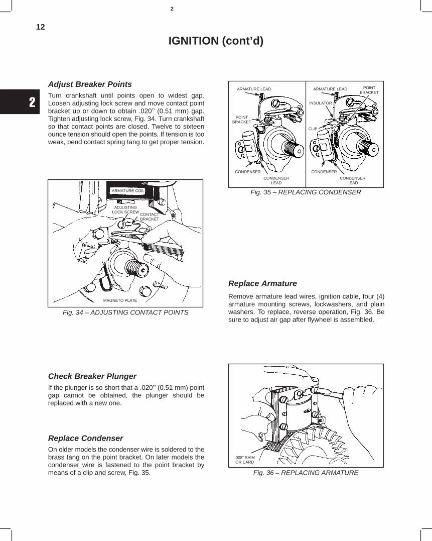
Adjust Breaker PointsTurn crankshaft until points open to widest gap.Loosen adjusting lock screw and move contact pointbracket up or down to obtain .020 (0.51 mm gap.Tighten adjusting lock screw, Fig. 34. Turn crankshaftso that contact points are closed. Twelve to sixteenounce tension should open the points. If tension is tooweak, bend contact spring tang to get proper tension.
Fig. 34 – ADJUSTING CONTACT POINTS
ARMATURE COIL
ADJUSTINGLOCK SCREW
CONTACTBRACKET
MAGNETO PLATE
Check Breaker PlungerIf the plunger is so short that a .020(0.51 mm) pointgap cannot be obtained, the plunger should bereplaced with a new one.
Replace CondenserOn older models the condenser wire is soldered to thebrass tang on the point bracket. On later models thecondenser wire is fastened to the point bracket bymeans of a clip and screw, Fig. 35.
Fig. 35 – REPLACING CONDENSER
ARMATURE LEAD
POINTBRACKET
CONDENSER
CONDENSERLEAD
INSULATOR
CLIP
ARMATURE LEAD POINTBRACKET
CONDENSER
CONDENSERLEAD
Replace Armature
Remove armature lead wires, ignition cable, four (4)armature mounting screws, lockwashers, and plainwashers. To replace, reverse operation, Fig. 36. Besure to adjust air gap after flywheel is assembled.
Fig. 36 – REPLACING ARMATURE
.008” SHIMOR CARD
13
2
IGNITION (cont’d)
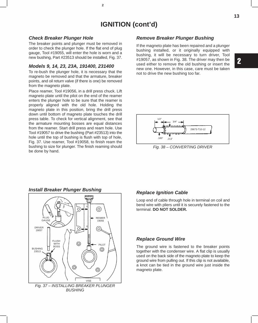
Check Breaker Plunger HoleThe breaker points and plunger must be removed inorder to check the plunger hole. If the flat end of pluggauge, Tool #19055, will enter the hole is worn and anew bushing, Part #23513 should be installed, Fig. 37.
Models 9, 14, 23, 23A, 191400, 231400To re-bush the plunger hole, it is necessary that themagneto be removed and that the armature, breakerpoints, and oil return valve (if there is one) be removedfrom the magneto plate.Place reamer, Tool #19056, in a drill press chuck. Liftmagneto plate until the pilot on the end of the reamerenters the plunger hole to be sure that the reamer isproperly aligned with the old hole. Holding themagneto plate in this position, bring the drill pressdown until bottom of magneto plate touches the drillpress table. To check for vertical alignment, see thatthe armature mounting bosses are equal distancesfrom the reamer. Start drill press and ream hole. UseTool #19057 to drive the bushing (Part #23513) into thehole until the top of bushing is flush with top of hole,Fig. 37. Use reamer, Tool #19058, to finish ream thebushing to size for plunger. The finish reaming shouldbe done by hand.
Install Breaker Plunger Bushing
Fig. 37 – INSTALLING BREAKER PLUNGERBUSHING
PLUGGAUGE
DRIVER19057
BUSHING23513
FLUSH WITHBOSS
REIMER19056
PILOT
VISE
X
X
Remove Breaker Plunger Bushing
If the magneto plate has been repaired and a plungerbushing installed, or it originally equipped withbushing, it will be necessary to turn driver, Tool#19057, as shown in Fig. 38. The driver may then beused either to remove the old bushing or insert thenew one. However, in this case, care must be takennot to drive the new bushing too far.
1/2”3/4”
.213”.183”
29673-T10-12
Fig. 38 – CONVERTING DRIVER
Replace Ignition Cable
Loop end of cable through hole in terminal on coil andbend wire with pliers until it is securely fastened to theterminal. DO NOT SOLDER.
Replace Ground Wire
The ground wire is fastened to the breaker pointstogether with the condenser wire. A flat clip is usuallyused on the back side of the magneto plate to keep theground wire from pulling out. If this clip is not available,a knot can be tied in the ground wire just inside themagneto plate.
14
2
IGNITION (cont’d)
Time Magneto
The magneto is always correctly timed when theflywheel is properly assembled. Do no attempt tochange timing by relocating any parts or filingcrankshaft flat.
Adjust Armature Air Gap
The air gap between flywheel and armature should befrom .002to .012.”(0.05 to 0.30 mm) A badly wornmagneto bearing may cause this gap to decreasewhen the engine is running.
Turn flywheel until magnets are directly below thearmature laminations. Raise armature and insert astrip of .008 (0.20 mm) brass shim stock, orInstruction Tag, MS-1342 (supplied with newarmatures) between the end of the armaturelaminations and the flywheel magnets. Press armaturedown and tighten screws. Pull shim out, Fig. 36.
NOTE: If a detached magneto assembly has beenrepaired, Instruction Tag, MS-1342 should besent to customer with the magneto. This willinstruct the customer on how to adjust thearmature air gap on his own engine.
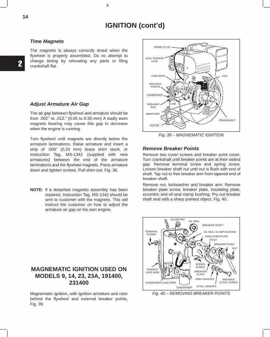
MAGNEMATIC IGNITION USED ONMODELS 9, 14, 23, 23A, 191400,
231400
Magnematic ignition, with ignition armature and rotorbehind the flywheel and external breaker points,Fig. 39.
Fig. 39 – MAGNEMATIC IGNITION
SPARK PLUG
HIGH TENSIONLEAD
CAM GEAR
BREAKERPOINTS
CONDENSER
CAMBREAKERBOX
ARMATURE
ROTOR
CRANKSHAFT
COIL
Remove Breaker PointsRemove two cover screws and breaker point cover.Turn crankshaft until breaker points are at their widestgap. Remove terminal screw and spring screw.Loosen breaker shaft nut until nut is flush with end ofshaft. Tap nut to free breaker arm from tapered end ofbreaker shaft.
Remove nut, lockwasher and breaker arm. Removebreaker plate screw, breaker plate, insulating plate,eccentric and oil seal clamp bushing. Pry out breakershaft seal with a sharp pointed object, Fig. 40.
Fig. 40 – REMOVING BREAKER POINTS
TERMINALSCREW
ECCENTRICOIL SEAL
BREAKER SHAFT
OIL SEAL CLAMP BUSHING
INSULATING PLATE
PIVOT
BREAKER POINT
NUT
BREAKERPLATE SCREW
SPRINGSCREW
BREAKERPLATE
FIBER WASHER
STEEL WASHERCONDENSER
PRIMARYLEAD WIRE
CONDENSER LEAD WIRE
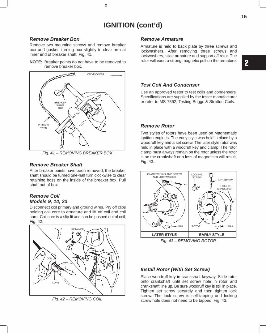
15
2
IGNITION (cont’d)
Remove Breaker BoxRemove two mounting screws and remove breakerbox and gasket, turning box slightly to clear arm atinner end of breaker shaft, Fig. 41.
NOTE: Breaker points do not have to be removed toremove breaker box.
Fig. 41 – REMOVING BREAKER BOX
VALVE COVER
BREAKERSHAFTARM
PRIMARYWIRE
Remove Breaker ShaftAfter breaker points have been removed, the breakershaft should be turned one-half turn clockwise to clearretaining boss on the inside of the breaker box. Pullshaft out of box.
Remove CoilModels 9, 14, 23Disconnect coil primary and ground wires. Pry off clipsholding coil core to armature and lift off coil and coilcore. Coil core is a slip fit and can be pushed out of coil,Fig. 42.
Fig. 42 – REMOVING COIL
RETAINER
CLIP
COIL
CORE
Remove ArmatureArmature is held to back plate by three screws andlockwashers. After removing three screws andlockwashers, slide armature and support off rotor. Therotor will exert a strong magnetic pull on the armature.
Test Coil And CondenserUse an approved tester to test coils and condensers.Specifications are supplied by the tester manufactureror refer to MS-7862, Testing Briggs & Stratton Coils.
Remove RotorTwo styles of rotors have been used on Magnematicignition engines. The early style was held in place by awoodruff key and a set screw. The later style rotor washeld in place with a woodruff key and clamp. The rotorclamp must always remain on the rotor unless the rotoris on the crankshaft or a loss of magnetism will result,Fig. 43.
Fig. 43 – REMOVING ROTOR
LATER STYLE EARLY STYLE
CLAMP WITH CLAMP SCREWAND LOCKWASHER
LOCKINGSCREW
SET SCREW
HOLE INCRANKSHAFT
KEYROTORKEY
Install Rotor (With Set Screw)Place woodruff key in crankshaft keyway. Slide rotoronto crankshaft until set screw hole in rotor andcrankshaft line up. Be sure woodruff key is still in place.Tighten set screw securely and then tighten lockscrew. The lock screw is self-tapping and lockingscrew hole does not need to be tapped, Fig. 43.
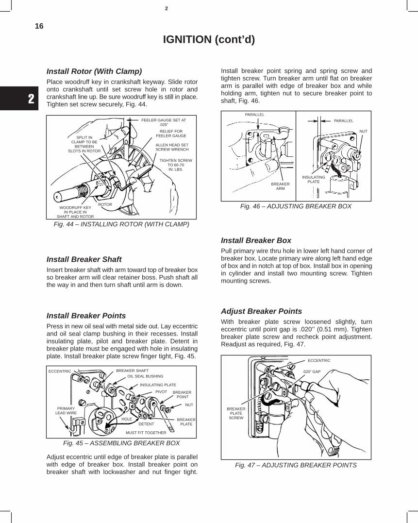
16
2
IGNITION (cont’d)
Install Rotor (With Clamp)Place woodruff key in crankshaft keyway. Slide rotoronto crankshaft until set screw hole in rotor andcrankshaft line up. Be sure woodruff key is still in place.Tighten set screw securely, Fig. 44.
Fig. 44 – INSTALLING ROTOR (WITH CLAMP)
FEELER GAUGE SET AT.025”
RELIEF FORFEELER GAUGE
ALLEN HEAD SETSCREW WRENCH
TIGHTEN SCREWTO 60-70IN. LBS.
ROTORWOODRUFF KEY
IN PLACE INSHAFT AND ROTOR
SPLIT INCLAMP TO BE
BETWEENSLOTS IN ROTOR
Install Breaker ShaftInsert breaker shaft with arm toward top of breaker boxso breaker arm will clear retainer boss. Push shaft allthe way in and then turn shaft until arm is down.
Install Breaker PointsPress in new oil seal with metal side out. Lay eccentricand oil seal clamp bushing in their recesses. Installinsulating plate, pilot and breaker plate. Detent inbreaker plate must be engaged with hole in insulatingplate. Install breaker plate screw finger tight, Fig. 45.
Fig. 45 – ASSEMBLING BREAKER BOX
ECCENTRIC
PRIMARYLEAD WIRE
BREAKER SHAFTOIL SEAL BUSHING
INSULATING PLATE
PIVOT BREAKER POINT
NUT
BREAKERPLATE
HOLEDETENT
MUST FIT TOGETHER
Adjust eccentric until edge of breaker plate is parallelwith edge of breaker box. Install breaker point onbreaker shaft with lockwasher and nut finger tight.
Install breaker point spring and spring screw andtighten screw. Turn breaker arm until flat on breakerarm is parallel with edge of breaker box and whileholding arm, tighten nut to secure breaker point toshaft, Fig. 46.
Fig. 46 – ADJUSTING BREAKER BOX
PARALLEL
BREAKERARM
PARALLEL
INSULATINGPLATE
NUT
Install Breaker BoxPull primary wire thru hole in lower left hand corner ofbreaker box. Locate primary wire along left hand edgeof box and in notch at top of box. Install box in openingin cylinder and install two mounting screw. Tightenmounting screws.
Adjust Breaker PointsWith breaker plate screw loosened slightly, turneccentric until point gap is .020(0.51 mm). Tightenbreaker plate screw and recheck point adjustment.Readjust as required, Fig. 47.
Fig. 47 – ADJUSTING BREAKER POINTS
ECCENTRIC
.020” GAP
BREAKERPLATE
SCREW
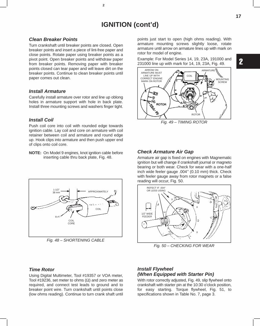
17
2
IGNITION (cont’d)
Clean Breaker PointsTurn crankshaft until breaker points are closed. Openbreaker points and insert a piece of lint-free paper andclose points. Rotate paper using breaker points as apivot point. Open breaker points and withdraw paperfrom breaker points. Removing paper with breakerpoints closed can tear paper and will leave dirt on thebreaker points. Continue to clean breaker points untilpaper comes out clean.
Install ArmatureCarefully install armature over rotor and line up oblongholes in armature support with hole in back plate.Install three mounting screws and washers finger tight.
Install CoilPush coil core into coil with rounded edge towardsignition cable. Lay coil and core on armature with coilretainer between coil and armature and round edgeup. Hook clips into armature and then push upper endof clips onto coil core.
NOTE: On Model 9 engines, knot ignition cable beforeinserting cable thru back plate, Fig. 48.
Fig. 48 – SHORTENING CABLE
1-1/2”38 mm APPROXIMATELY
COIL
COILCORE
Time RotorUsing Digital Multimeter, Tool #19357 or VOA meter,Tool #19236, set meter to ohms (Ω) and zero meter asrequired, and connect test leads to ground and tobreaker point wire. Turn crankshaft until points close(low ohms reading). Continue to turn crank shaft until
points just start to open (high ohms reading). Witharmature mounting screws slightly loose, rotatearmature until arrow on armature lines up with mark onrotor for model of engine.
Example: For Model Series 14, 19, 23A, 191000 and231000 line up with mark for 14, 19, 23A, Fig. 49.
Fig. 49 – TIMING ROTOR
ARROW ONARMATURE MUST
LINE UP WITHCORRECT ENGINEMARK ON ROTOR
COIL
ARMATURE
MOUNTINGSCREW
ROTOR
Check Armature Air GapArmature air gap is fixed on engines with Magnematicignition but will change if crankshaft journal or magnetobearing or both wear. Check for wear with a one-halfinch wide feeler gauge .004(0.10 mm) thick. Checkwith feeler gauge away from rotor magnets or a falsereading will occur, Fig. 50.
Fig. 50 – CHECKING FOR WEAR
REFECT IF .004”OR LESS USING
1/2” WIDEFEEDER
X
X
X
X
Install Flywheel(When Equipped with Starter Pin)With rotor correctly adjusted, Fig. 49, slip flywheel ontocrankshaft with starter pin at the 10:30 o’clock position,for easy starting. Torque flywheel, Fig. 51, tospecifications shown in Table No. 7, page 3.
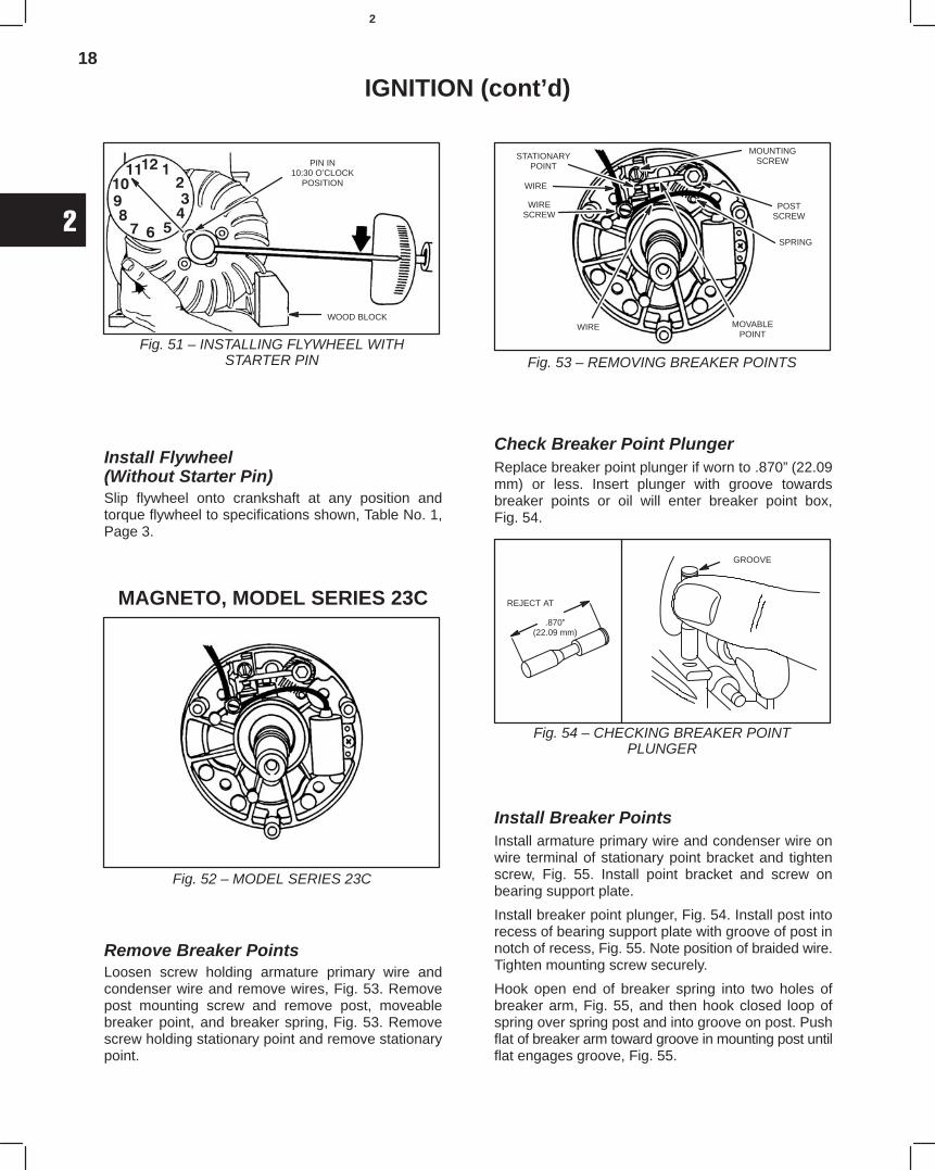
18
2
IGNITION (cont’d)
Fig. 51 – INSTALLING FLYWHEEL WITHSTARTER PIN
PIN IN10:30 O’CLOCK
POSITION
WOOD BLOCK
Install Flywheel(Without Starter Pin)Slip flywheel onto crankshaft at any position andtorque flywheel to specifications shown, Table No. 1,Page 3.
MAGNETO, MODEL SERIES 23C
Fig. 52 – MODEL SERIES 23C
Remove Breaker PointsLoosen screw holding armature primary wire andcondenser wire and remove wires, Fig. 53. Removepost mounting screw and remove post, moveablebreaker point, and breaker spring, Fig. 53. Removescrew holding stationary point and remove stationarypoint.
Fig. 53 – REMOVING BREAKER POINTS
STATIONARYPOINT
WIRESCREW
WIRE
MOUNTINGSCREW
POSTSCREW
SPRING
MOVABLEPOINT
WIRE
Check Breaker Point PlungerReplace breaker point plunger if worn to .870”(22.09mm) or less. Insert plunger with groove towardsbreaker points or oil will enter breaker point box,Fig. 54.
GROOVE
REJECT AT
Fig. 54 – CHECKING BREAKER POINTPLUNGER
.870”(22.09 mm)
Install Breaker PointsInstall armature primary wire and condenser wire onwire terminal of stationary point bracket and tightenscrew, Fig. 55. Install point bracket and screw onbearing support plate.
Install breaker point plunger, Fig. 54. Install post intorecess of bearing support plate with groove of post innotch of recess, Fig. 55. Note position of braided wire.Tighten mounting screw securely.
Hook open end of breaker spring into two holes ofbreaker arm, Fig. 55, and then hook closed loop ofspring over spring post and into groove on post. Pushflat of breaker arm toward groove in mounting post untilflat engages groove, Fig. 55.
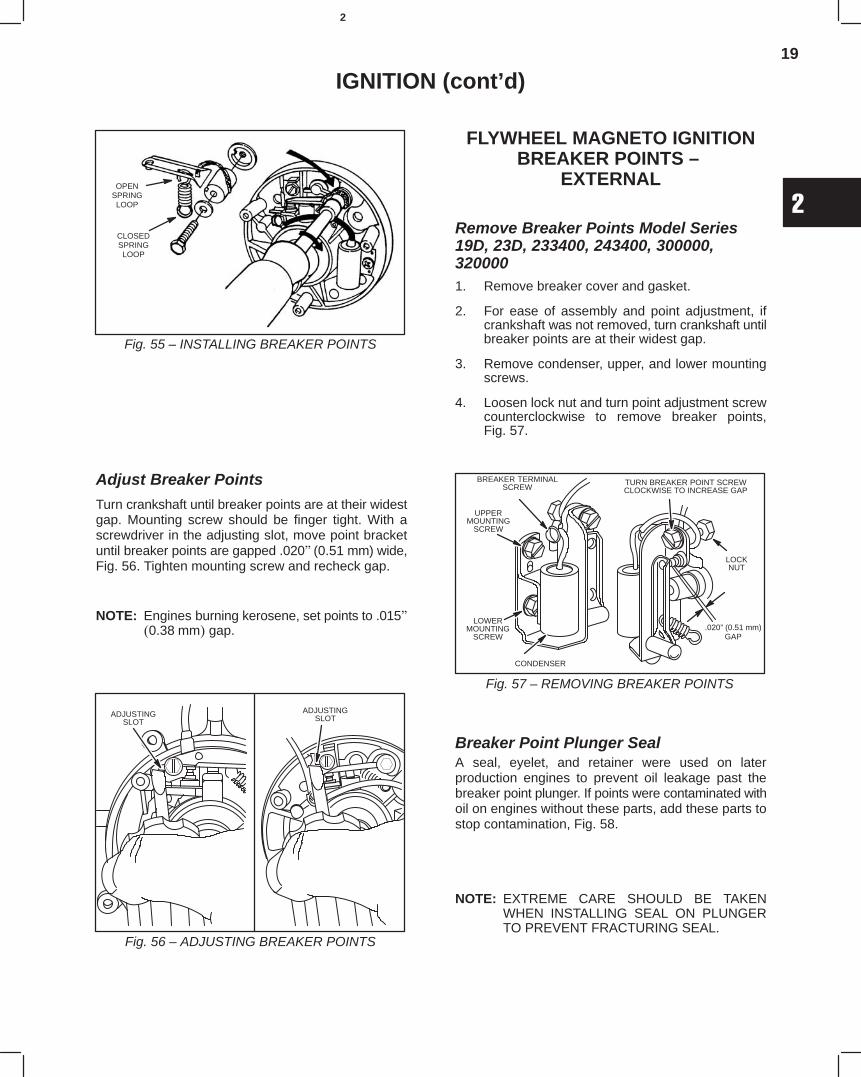
19
2
IGNITION (cont’d)
Fig. 55 – INSTALLING BREAKER POINTS
OPENSPRINGLOOP
CLOSEDSPRINGLOOP
Adjust Breaker Points
Turn crankshaft until breaker points are at their widestgap. Mounting screw should be finger tight. With ascrewdriver in the adjusting slot, move point bracketuntil breaker points are gapped .020(0.51 mm) wide,Fig. 56. Tighten mounting screw and recheck gap.
NOTE: Engines burning kerosene, set points to .0150.38mm gap.
Fig. 56 – ADJUSTING BREAKER POINTS
ADJUSTINGSLOT
ADJUSTINGSLOT
FLYWHEEL MAGNETO IGNITIONBREAKER POINTS –
EXTERNAL
Remove Breaker Points Model Series19D, 23D, 233400, 243400, 300000,3200001. Remove breaker cover and gasket.
2. For ease of assembly and point adjustment, ifcrankshaft was not removed, turn crankshaft untilbreaker points are at their widest gap.
3. Remove condenser, upper, and lower mountingscrews.
4. Loosen lock nut and turn point adjustment screwcounterclockwise to remove breaker points,Fig. 57.
BREAKER TERMINALSCREW
UPPERMOUNTING
SCREW
LOWERMOUNTING
SCREW
CONDENSER
TURN BREAKER POINT SCREWCLOCKWISE TO INCREASE GAP
LOCKNUT
.020” (0.51 mm)GAP
Fig. 57 – REMOVING BREAKER POINTS
Breaker Point Plunger SealA seal, eyelet, and retainer were used on laterproduction engines to prevent oil leakage past thebreaker point plunger. If points were contaminated withoil on engines without these parts, add these parts tostop contamination, Fig. 58.
NOTE: EXTREME CARE SHOULD BE TAKENWHEN INSTALLING SEAL ON PLUNGERTO PREVENT FRACTURING SEAL.
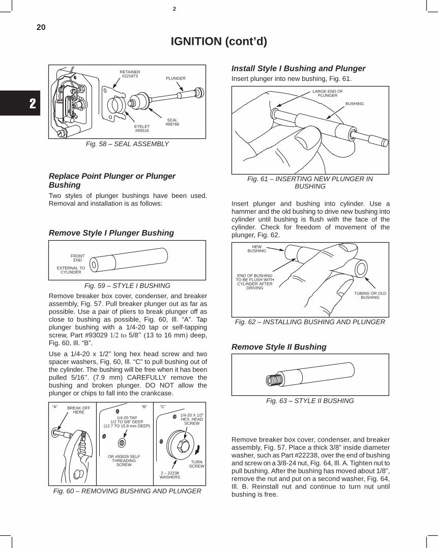
20
2
IGNITION (cont’d)
RETAINER#221873
SEAL#68768
PLUNGER
EYELET#93516
Fig. 58 – SEAL ASSEMBLY
Replace Point Plunger or PlungerBushingTwo styles of plunger bushings have been used.Removal and installation is as follows:
Remove Style I Plunger Bushing
FRONTEND
Fig. 59 – STYLE I BUSHING
EXTERNAL TOCYLINDER
Remove breaker box cover, condenser, and breakerassembly, Fig. 57. Pull breaker plunger out as far aspossible. Use a pair of pliers to break plunger off asclose to bushing as possible, Fig. 60, Ill. “A”. Tapplunger bushing with a 1/4-20 tap or self-tappingscrew, Part #93029 5/8 13 to 16 mm deep,Fig. 60, Ill. “B”.
Use a 1/4-20 x 1/2” long hex head screw and twospacer washers, Fig. 60, Ill. “C” to pull bushing out ofthe cylinder. The bushing will be free when it has beenpulled 5/16 (7.9 mm) CAREFULLY remove thebushing and broken plunger. DO NOT allow theplunger or chips to fall into the crankcase.
BREAK OFFHERE
1/4-20 TAP1/2 TO 5/8” DEEP
(12.7 TO 15.9 mm DEEP)
OR #93029 SELFTHREADING
SCREW
2 – 22238WASHERS
1/4-20 X 1/2”HEX. HEAD
SCREW
TURNSCREW
Fig. 60 – REMOVING BUSHING AND PLUNGER
“A” “B” “C”
Install Style I Bushing and PlungerInsert plunger into new bushing, Fig. 61.
BUSHING
LARGE END OFPLUNGER
Fig. 61 – INSERTING NEW PLUNGER INBUSHING
Insert plunger and bushing into cylinder. Use ahammer and the old bushing to drive new bushing intocylinder until bushing is flush with the face of thecylinder. Check for freedom of movement of theplunger, Fig. 62.
NEWBUSHING
TUBING OR OLDBUSHING
END OF BUSHINGTO BE FLUSH WITHCYLINDER AFTER
DRIVING
Fig. 62 – INSTALLING BUSHING AND PLUNGER
Remove Style II Bushing
Fig. 63 – STYLE II BUSHING
Remove breaker box cover, condenser, and breakerassembly, Fig. 57. Place a thick 3/8” inside diameterwasher, such as Part #22238, over the end of bushingand screw on a 3/8-24 nut, Fig. 64, Ill. A. Tighten nut topull bushing. After the bushing has moved about 1/8”,remove the nut and put on a second washer, Fig. 64,Ill. B. Reinstall nut and continue to turn nut untilbushing is free.
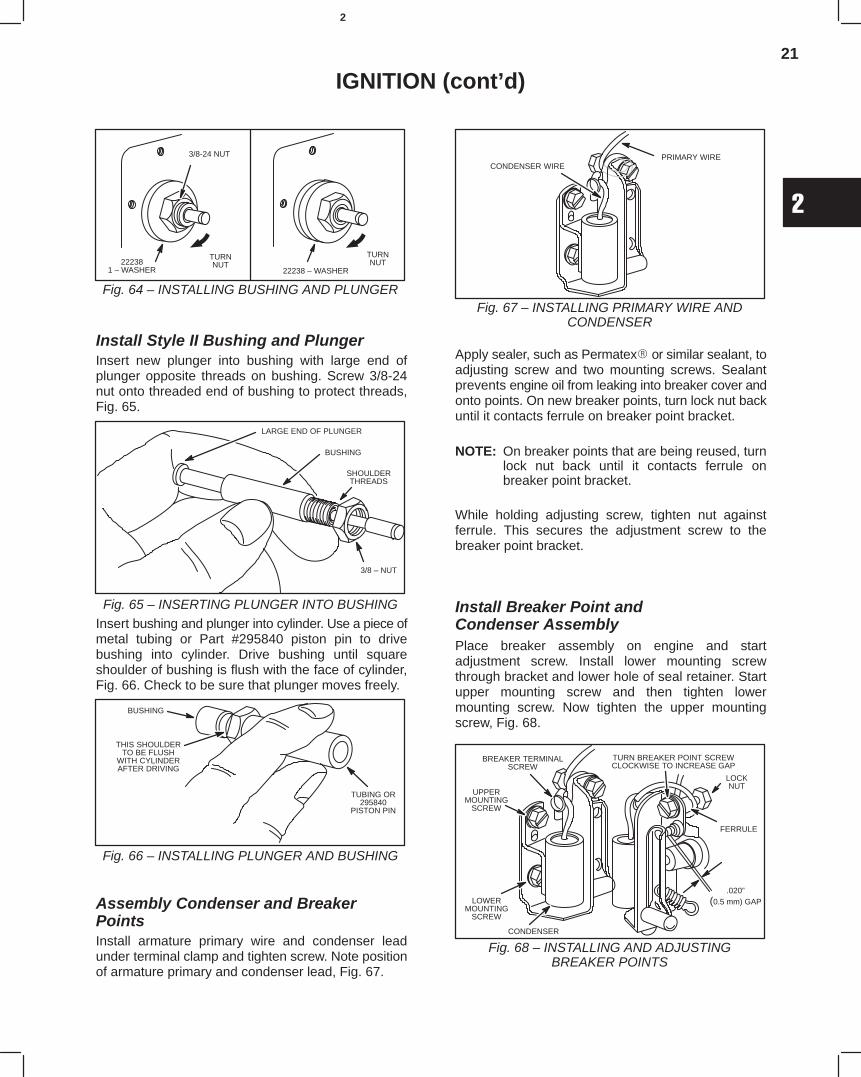
21
2
IGNITION (cont’d)
222381 – WASHER
3/8-24 NUT
TURNNUT
22238 – WASHER
TURNNUT
Fig. 64 – INSTALLING BUSHING AND PLUNGER
Install Style II Bushing and PlungerInsert new plunger into bushing with large end ofplunger opposite threads on bushing. Screw 3/8-24nut onto threaded end of bushing to protect threads,Fig. 65.
BUSHING
LARGE END OF PLUNGER
SHOULDERTHREADS
3/8 – NUT
Fig. 65 – INSERTING PLUNGER INTO BUSHINGInsert bushing and plunger into cylinder. Use a piece ofmetal tubing or Part #295840 piston pin to drivebushing into cylinder. Drive bushing until squareshoulder of bushing is flush with the face of cylinder,Fig. 66. Check to be sure that plunger moves freely.
BUSHING
THIS SHOULDERTO BE FLUSH
WITH CYLINDERAFTER DRIVING
TUBING OR295840
PISTON PIN
Fig. 66 – INSTALLING PLUNGER AND BUSHING
Assembly Condenser and BreakerPointsInstall armature primary wire and condenser leadunder terminal clamp and tighten screw. Note positionof armature primary and condenser lead, Fig. 67.
CONDENSER WIREPRIMARY WIRE
Fig. 67 – INSTALLING PRIMARY WIRE ANDCONDENSER
Apply sealer, such as Permatex or similar sealant, toadjusting screw and two mounting screws. Sealantprevents engine oil from leaking into breaker cover andonto points. On new breaker points, turn lock nut backuntil it contacts ferrule on breaker point bracket.
NOTE: On breaker points that are being reused, turnlock nut back until it contacts ferrule onbreaker point bracket.
While holding adjusting screw, tighten nut againstferrule. This secures the adjustment screw to thebreaker point bracket.
Install Breaker Point andCondenser AssemblyPlace breaker assembly on engine and startadjustment screw. Install lower mounting screwthrough bracket and lower hole of seal retainer. Startupper mounting screw and then tighten lowermounting screw. Now tighten the upper mountingscrew, Fig. 68.
BREAKER TERMINALSCREW
UPPERMOUNTING
SCREW
LOWERMOUNTING
SCREW
CONDENSER
TURN BREAKER POINT SCREWCLOCKWISE TO INCREASE GAP
LOCKNUT
.020”(0.5 mm) GAP
Fig. 68 – INSTALLING AND ADJUSTINGBREAKER POINTS
FERRULE
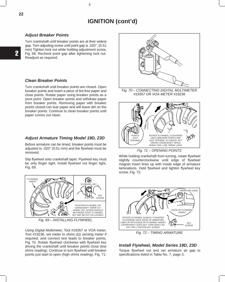
22
2
IGNITION (cont’d)
Adjust Breaker PointsTurn crankshaft until breaker points are at their widestgap. Turn adjusting screw until point gap is .020(0.51mm) Tighten lock nut while holding adjustment screw,Fig. 68. Recheck point gap after tightening lock nut.Readjust as required.
Clean Breaker PointsTurn crankshaft until breaker points are closed. Openbreaker points and insert a piece of lint-free paper andclose points. Rotate paper using breaker points as apivot point. Open breaker points and withdraw paperfrom breaker points. Removing paper with breakerpoints closed can tear paper and will leave dirt on thebreaker points. Continue to clean breaker points untilpaper comes out clean.
Adjust Armature Timing Model 19D, 23DBefore armature can be timed, breaker points must beadjusted to .020(0.51 mm) and the flywheel must beremoved.
Slip flywheel onto crankshaft taper. Flywheel key mustbe only finger tight. Install flywheel nut finger tight,Fig. 69.
Fig. 69 – INSTALLING FLYWHEEL
FLYWHEEL KEY
KEYSCREW
FLYWHEELINSERT
POSITION FLYWHEEL ONCRANKSHAFT TAPER FLY-
WHEEL KEY SCREW SHOULDBE FINGER TIGHT. FLYWHEEL
NUT MAY BE PUT ON LOOSELY.
Using Digital Multimeter, Tool #19357 or VOA meter,Tool #19236, set meter to ohms (Ω) zeroing meter ifrequired, and connect test leads to breaker points,Fig. 70. Rotate flywheel clockwise with flywheel keydriving the crankshaft until breaker points close (lowohms reading). Continue to turn flywheel until breakerpoints just start to open (high ohms reading), Fig. 71.
Fig. 70 – CONNECTING DIGITAL MULTIMETER#19357 OR VOA METER #19236
Fig. 71 – OPENING POINTS
POINTSJUST
OPENING
ROTATE FLYWHEEL CLOCKWISEUNTIL BREAKER POINTS ARE
JUST OPENING. (FLYWHEEL KEYDRIVES CRANKSHAFT WHILE
DOING THIS.) USE TIMING LIGHT.
While holding crankshaft from turning, rotate flywheelslightly counterclockwise until edge of flywheelmagnet insert lines up with inside edge of armaturelaminations. Hold flywheel and tighten flywheel keyscrew, Fig. 72.
Fig. 72 – TIMING ARMATURE
ROTATE FLYWHEEL SLIGHTLY COUNTERCLOCKWISE UNTIL EDGE OF ARMATURE
LINES UP WITH EDGE OF FLYWHEEL INSERT.(CRANKSHAFT DOES NOT TURN WHILE DO-
ING THIS.) TIGHTEN KEY SCREW.
ARMATURE EDGE
EDGE OF FLYWHEELINSERT
KEYSCREW
Install Flywheel, Model Series 19D, 23DTorque flywheel nut and set armature air gap tospecifications listed in Table No. 7, page 3.
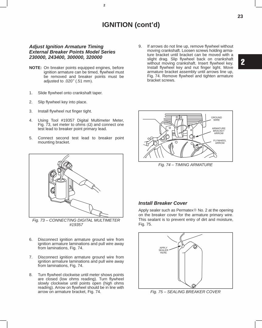
23
2
IGNITION (cont’d)
Adjust Ignition Armature TimingExternal Breaker Points Model Series230000, 243400, 300000, 320000
NOTE: On breaker points equipped engines, beforeignition armature can be timed, flywheel mustbe removed and breaker points must beadjusted to .020(.51 mm.
1. Slide flywheel onto crankshaft taper.
2. Slip flywheel key into place.
3. Install flywheel nut finger tight.
4. Using Tool #19357 Digital Multimeter Meter,Fig. 73, set meter to ohms (Ω) and connect onetest lead to breaker point primary lead.
5. Connect second test lead to breaker pointmounting bracket.
Fig. 73 – CONNECTING DIGITAL MULTIMETER#19357
6. Disconnect ignition armature ground wire fromignition armature laminations and pull wire awayfrom laminations, Fig. 74.
7. Disconnect ignition armature ground wire fromignition armature laminations and pull wire awayfrom laminations, Fig. 74.
8. Turn flywheel clockwise until meter shows pointsare closed (low ohms reading). Turn flywheelslowly clockwise until points open (high ohmsreading). Arrow on flywheel should be in line witharrow on armature bracket, Fig. 74.
9. If arrows do not line up, remove flywheel withoutmoving crankshaft. Loosen screws holding arma-ture bracket until bracket can be moved with aslight drag. Slip flywheel back on crankshaftwithout moving crankshaft. Insert flywheel key.Install flywheel key and nut finger tight. Movearmature bracket assembly until arrows line up,Fig. 74. Remove flywheel and tighten armaturebracket screws.
Fig. 74 – TIMING ARMATURE
GROUNDWIRE
ARMATUREBRACKETARROW
FLYWHEELARROW
Install Breaker CoverApply sealer such as Permatex No. 2 at the openingon the breaker cover for the armature primary wire.This sealant is to prevent entry of dirt and moisture,Fig. 75.
APPLYSEALER
HERE
Fig. 75 – SEALING BREAKER COVER
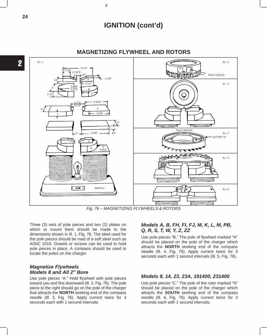
24
2
IGNITION (cont’d)
MAGNETIZING FLYWHEEL AND ROTORS
Fig. 76 – MAGNETIZING FLYWHEELS & ROTORS
5-1/2”1-7/16”
2-1/8”
2-7/8”R
A
B
2”
5.980”5.975”
1/2”
4”
1-1/2”
3.173”3.170”
5-5/16”
C4”
1 4-3/4”
4”
3/4”5-5/8”2”
A
B NPOLE
SWITCH
2-1/2”
1/2”
ILL. 1 ILL. 2
ILL. 3
ILL. 4
ILL. 5
ILL. 6
POLE PIECES
POLE PIECES
LETTER “N”
Three (3) sets of pole pieces and two (2) plates onwhich to mount them should be made to thedimensions shown in Ill. 1, Fig. 76. The steel used forthe pole pieces should be mad of a soft steel such asAISIC 1019. Dowels or screws can be used to holdpole pieces in place. A compass should be used tolocate the poles on the charger.
Magnetize FlywheelsModels 8 and All 2” BoreUse pole pieces “A.” Hold flywheel with pole piecestoward you and fins downward (Ill. 2, Fig. 76). The polepiece to the right should go on the pole of the chargerthat attracts the NORTH seeking end of the compassneedle (Ill. 3, Fig. 76). Apply current twice for 3seconds each with 1 second intervals.
Models A, B, FH, FI, FJ, M, K, L, M, PB,Q, R, S, T, W, Y, Z, ZZUse pole pieces “B.” The pole of flywheel marked “N”should be placed on the pole of the charger whichattracts the NORTH seeking end of the compassneedle (Ill. 4, Fig. 76). Apply current twice for 3seconds each with 1 second intervals (Ill. 5, Fig. 76).
Models 9, 14, 23, 23A, 191400, 231400Use pole pieces “C.” The pole of the rotor marked “N”should be placed on the pole of the charger whichattracts the SOUTH seeking end of the compassneedle (Ill. 6, Fig. 76). Apply current twice for 3seconds each with 1 second intervals.
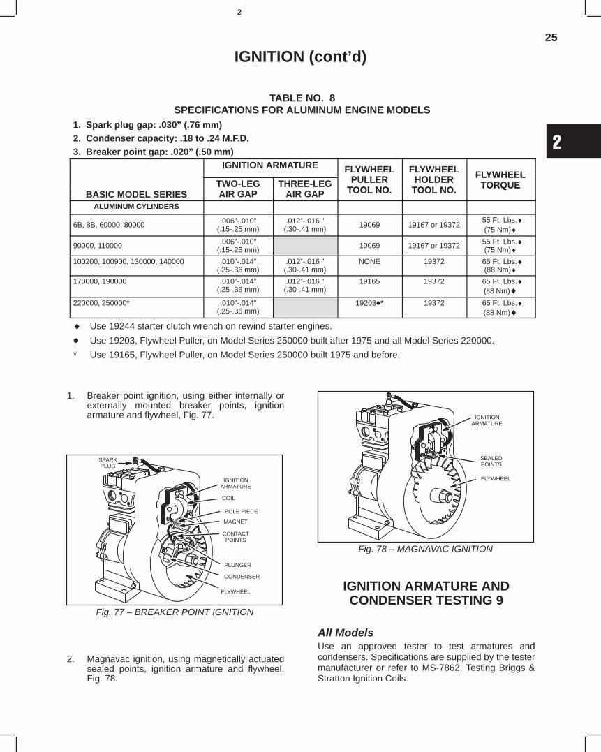
25
2
IGNITION (cont’d)
TABLE NO. 8SPECIFICATIONS FOR ALUMINUM ENGINE MODELS
1. Spark plug gap: .030 (.76 mm)2. Condenser capacity: .18 to .24 M.F.D.3. Breaker point gap: .020(.50 mm)
IGNITION ARMATURE FLYWHEELPULLER
FLYWHEELHOLDER FLYWHEEL
TWO-LEG THREE-LEG PULLERTOOL NO
HOLDERTOOL NO
FLYWHEELTORQUE
BASIC MODEL SERIESTWO LEGAIR GAP
THREE LEGAIR GAP TOOL NO. TOOL NO. TORQUE
ALUMINUM CYLINDERS
6B, 8B, 60000, 80000 .006”-.010”(.15-.25 mm)
.012”-.016 ”(.30-.41 mm) 19069 19167 or 19372
55 Ft. Lbs.♦(75 Nm)♦
90000, 110000 .006”-.010”(.15-.25 mm) 19069 19167 or 19372 55 Ft. Lbs.♦
(75 Nm)♦100200, 100900, 130000, 140000 .010”-.014”
(.25-.36 mm).012”-.016 ”(.30-.41 mm)
NONE 19372 65 Ft. Lbs.♦(88 Nm)♦
170000, 190000 .010”-.014”(.25-.36 mm)
.012”-.016 ”(.30-.41 mm)
19165 19372 65 Ft. Lbs.♦(88 Nm)♦
220000, 250000* .010”-.014”(.25-.36 mm)
19203* 19372 65 Ft. Lbs.♦(88 Nm)♦
♦ Use 19244 starter clutch wrench on rewind starter engines.
Use 19203, Flywheel Puller, on Model Series 250000 built after 1975 and all Model Series 220000.
* Use 19165, Flywheel Puller, on Model Series 250000 built 1975 and before.
1. Breaker point ignition, using either internally orexternally mounted breaker points, ignitionarmature and flywheel, Fig. 77.
ÈÈÍ
IGNITIONARMATURE
CONTACTPOINTS
CONDENSER
COIL
POLE PIECE
FLYWHEEL
MAGNET
PLUNGER
SPARKPLUG
Fig. 77 – BREAKER POINT IGNITION
2. Magnavac ignition, using magnetically actuatedsealed points, ignition armature and flywheel,Fig. 78.
IGNITIONARMATURE
SEALEDPOINTS
FLYWHEEL
Fig. 78 – MAGNAVAC IGNITION
IGNITION ARMATURE ANDCONDENSER TESTING 9
All ModelsUse an approved tester to test armatures andcondensers. Specifications are supplied by the testermanufacturer or refer to MS-7862, Testing Briggs &Stratton Ignition Coils.
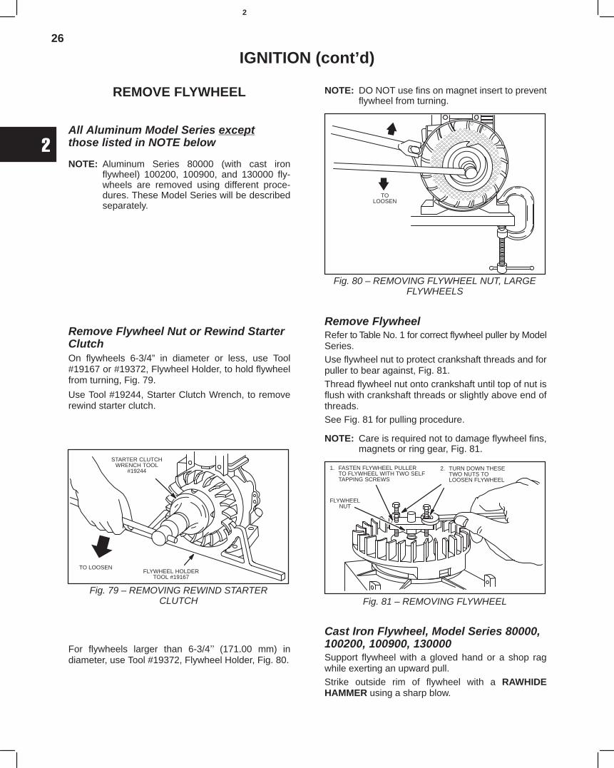
26
2
IGNITION (cont’d)
REMOVE FLYWHEEL
All Aluminum Model Series exceptthose listed in NOTE below
NOTE: Aluminum Series 80000 (with cast ironflywheel) 100200, 100900, and 130000 fly-wheels are removed using different proce-dures. These Model Series will be describedseparately.
Remove Flywheel Nut or Rewind StarterClutchOn flywheels 6-3/4” in diameter or less, use Tool#19167 or #19372, Flywheel Holder, to hold flywheelfrom turning, Fig. 79.
Use Tool #19244, Starter Clutch Wrench, to removerewind starter clutch.
TO LOOSENFLYWHEEL HOLDER
TOOL #19167
STARTER CLUTCHWRENCH TOOL
#19244
Fig. 79 – REMOVING REWIND STARTERCLUTCH
For flywheels larger than 6-3/4 (171.00 mm) indiameter, use Tool #19372, Flywheel Holder, Fig. 80.
NOTE: DO NOT use fins on magnet insert to preventflywheel from turning.
TOLOOSEN
Fig. 80 – REMOVING FLYWHEEL NUT, LARGEFLYWHEELS
Remove FlywheelRefer to Table No. 1 for correct flywheel puller by ModelSeries.Use flywheel nut to protect crankshaft threads and forpuller to bear against, Fig. 81.Thread flywheel nut onto crankshaft until top of nut isflush with crankshaft threads or slightly above end ofthreads.See Fig. 81 for pulling procedure.
NOTE: Care is required not to damage flywheel fins,magnets or ring gear, Fig. 81.
1. FASTEN FLYWHEEL PULLERTO FLYWHEEL WITH TWO SELFTAPPING SCREWS
2. TURN DOWN THESETWO NUTS TOLOOSEN FLYWHEEL
FLYWHEELNUT
Fig. 81 – REMOVING FLYWHEEL
Cast Iron Flywheel, Model Series 80000,100200, 100900, 130000Support flywheel with a gloved hand or a shop ragwhile exerting an upward pull.Strike outside rim of flywheel with a RAWHIDEHAMMER using a sharp blow.
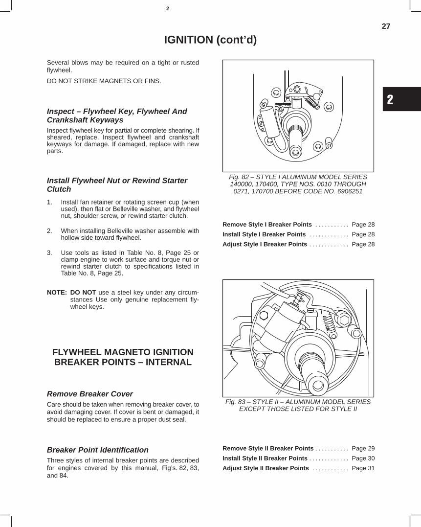
27
2
IGNITION (cont’d)
Several blows may be required on a tight or rustedflywheel.
DO NOT STRIKE MAGNETS OR FINS.
Inspect – Flywheel Key, Flywheel AndCrankshaft KeywaysInspect flywheel key for partial or complete shearing. Ifsheared, replace. Inspect flywheel and crankshaftkeyways for damage. If damaged, replace with newparts.
Install Flywheel Nut or Rewind StarterClutch
1. Install fan retainer or rotating screen cup (whenused), then flat or Belleville washer, and flywheelnut, shoulder screw, or rewind starter clutch.
2. When installing Belleville washer assemble withhollow side toward flywheel.
3. Use tools as listed in Table No. 8, Page 25 orclamp engine to work surface and torque nut orrewind starter clutch to specifications listed inTable No. 8, Page 25.
NOTE: DO NOT use a steel key under any circum-stances Use only genuine replacement fly-wheel keys.
FLYWHEEL MAGNETO IGNITIONBREAKER POINTS – INTERNAL
Remove Breaker CoverCare should be taken when removing breaker cover, toavoid damaging cover. If cover is bent or damaged, itshould be replaced to ensure a proper dust seal.
Breaker Point IdentificationThree styles of internal breaker points are describedfor engines covered by this manual, Fig’s. 82, 83,and 84.
Fig. 82 – STYLE I ALUMINUM MODEL SERIES140000, 170400, TYPE NOS. 0010 THROUGH0271, 170700 BEFORE CODE NO. 6906251
Remove Style I Breaker Points Page 28. . . . . . . . . . .
Install Style I Breaker Points Page 28. . . . . . . . . . . . .
Adjust Style I Breaker Points Page 28. . . . . . . . . . . . .
Fig. 83 – STYLE II – ALUMINUM MODEL SERIESEXCEPT THOSE LISTED FOR STYLE II
Remove Style II Breaker Points Page 29. . . . . . . . . . .
Install Style II Breaker Points Page 30. . . . . . . . . . . . .
Adjust Style II Breaker Points Page 31. . . . . . . . . . . .
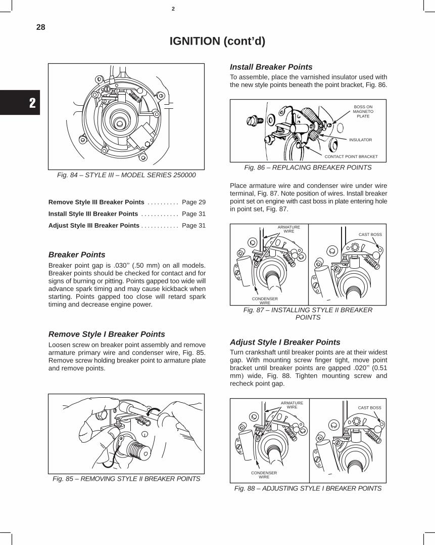
28
2
IGNITION (cont’d)
Fig. 84 – STYLE III – MODEL SERIES 250000
Remove Style III Breaker Points Page 29. . . . . . . . . .
Install Style III Breaker Points Page 31. . . . . . . . . . . .
Adjust Style III Breaker Points Page 31. . . . . . . . . . . .
Breaker PointsBreaker point gap is .030 (.50 mm) on all models.Breaker points should be checked for contact and forsigns of burning or pitting. Points gapped too wide willadvance spark timing and may cause kickback whenstarting. Points gapped too close will retard sparktiming and decrease engine power.
Remove Style I Breaker PointsLoosen screw on breaker point assembly and removearmature primary wire and condenser wire, Fig. 85.Remove screw holding breaker point to armature plateand remove points.
Fig. 85 – REMOVING STYLE II BREAKER POINTS
Install Breaker PointsTo assemble, place the varnished insulator used withthe new style points beneath the point bracket, Fig. 86.
Fig. 86 – REPLACING BREAKER POINTS
BOSS ONMAGNETO
PLATE
INSULATOR
CONTACT POINT BRACKET
Place armature wire and condenser wire under wireterminal, Fig. 87. Note position of wires. Install breakerpoint set on engine with cast boss in plate entering holein point set, Fig. 87.
Fig. 87 – INSTALLING STYLE II BREAKERPOINTS
ARMATUREWIRE
CONDENSERWIRE
CAST BOSS
Adjust Style I Breaker PointsTurn crankshaft until breaker points are at their widestgap. With mounting screw finger tight, move pointbracket until breaker points are gapped .020 (0.51mm wide, Fig. 88. Tighten mounting screw andrecheck point gap.
Fig. 88 – ADJUSTING STYLE I BREAKER POINTS
ARMATUREWIRE
CONDENSERWIRE
CAST BOSS
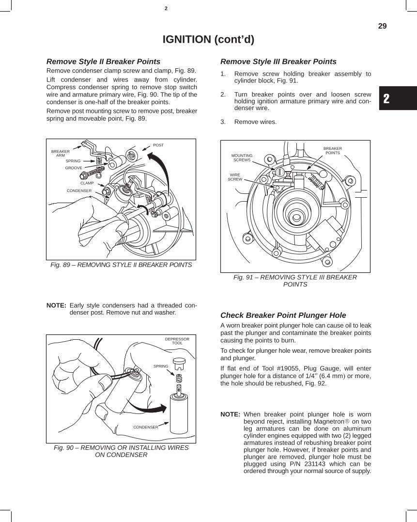
29
2
IGNITION (cont’d)
Remove Style II Breaker PointsRemove condenser clamp screw and clamp, Fig. 89.Lift condenser and wires away from cylinder.Compress condenser spring to remove stop switchwire and armature primary wire, Fig. 90. The tip of thecondenser is one-half of the breaker points.Remove post mounting screw to remove post, breakerspring and moveable point, Fig. 89.
BREAKERARM
SPRING
GROOVE
CONDENSER
POST
CLAMP
Fig. 89 – REMOVING STYLE II BREAKER POINTS
NOTE: Early style condensers had a threaded con-denser post. Remove nut and washer.
DEPRESSORTOOL
SPRING
CONDENSER
Fig. 90 – REMOVING OR INSTALLING WIRESON CONDENSER
Remove Style III Breaker Points
1. Remove screw holding breaker assembly tocylinder block, Fig. 91.
2. Turn breaker points over and loosen screwholding ignition armature primary wire and con-denser wire.
3. Remove wires.
MOUNTINGSCREWS
BREAKERPOINTS
WIRESCREW
Fig. 91 – REMOVING STYLE III BREAKERPOINTS
Check Breaker Point Plunger HoleA worn breaker point plunger hole can cause oil to leakpast the plunger and contaminate the breaker pointscausing the points to burn.
To check for plunger hole wear, remove breaker pointsand plunger.
If flat end of Tool #19055, Plug Gauge, will enterplunger hole for a distance of 1/4(6.4 mm or more,the hole should be rebushed, Fig. 92.
NOTE: When breaker point plunger hole is wornbeyond reject, installing Magnetron on twoleg armatures can be done on aluminumcylinder engines equipped with two (2) leggedarmatures instead of rebushing breaker pointplunger hole. However, if breaker points andplunger are removed, plunger hole must beplugged using P/N 231143 which can beordered through your normal source of supply.
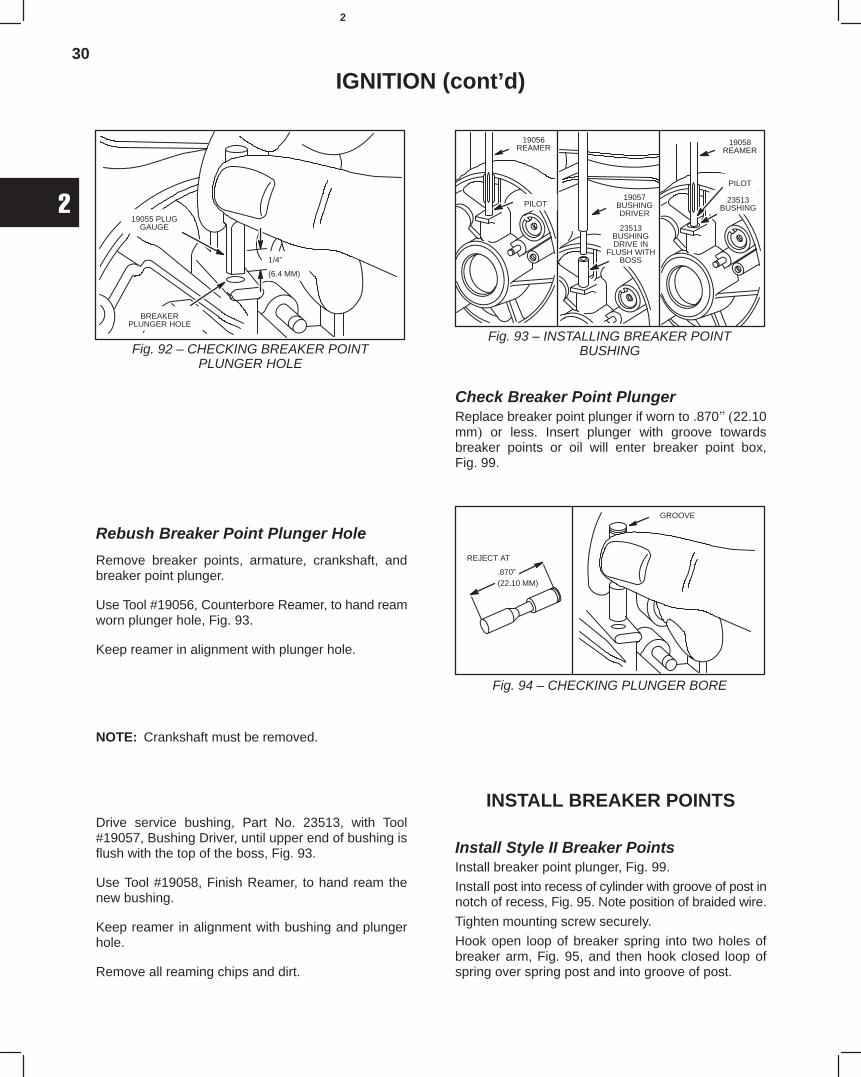
30
2
IGNITION (cont’d)
1/4”
(6.4 MM)
BREAKERPLUNGER HOLE
19055 PLUGGAUGE
Fig. 92 – CHECKING BREAKER POINTPLUNGER HOLE
Rebush Breaker Point Plunger Hole
Remove breaker points, armature, crankshaft, andbreaker point plunger.
Use Tool #19056, Counterbore Reamer, to hand reamworn plunger hole, Fig. 93.
Keep reamer in alignment with plunger hole.
NOTE: Crankshaft must be removed.
Drive service bushing, Part No. 23513, with Tool#19057, Bushing Driver, until upper end of bushing isflush with the top of the boss, Fig. 93.
Use Tool #19058, Finish Reamer, to hand ream thenew bushing.
Keep reamer in alignment with bushing and plungerhole.
Remove all reaming chips and dirt.
19056REAMER
PILOT19057
BUSHINGDRIVER
23513BUSHINGDRIVE IN
FLUSH WITHBOSS
19058REAMER
23513BUSHING
PILOT
Fig. 93 – INSTALLING BREAKER POINTBUSHING
Check Breaker Point PlungerReplace breaker point plunger if worn to .87022.10mm or less. Insert plunger with groove towardsbreaker points or oil will enter breaker point box,Fig. 99.
GROOVE
REJECT AT
.870”(22.10 MM)
Fig. 94 – CHECKING PLUNGER BORE
INSTALL BREAKER POINTS
Install Style II Breaker PointsInstall breaker point plunger, Fig. 99.
Install post into recess of cylinder with groove of post innotch of recess, Fig. 95. Note position of braided wire.
Tighten mounting screw securely.
Hook open loop of breaker spring into two holes ofbreaker arm, Fig. 95, and then hook closed loop ofspring over spring post and into groove of post.
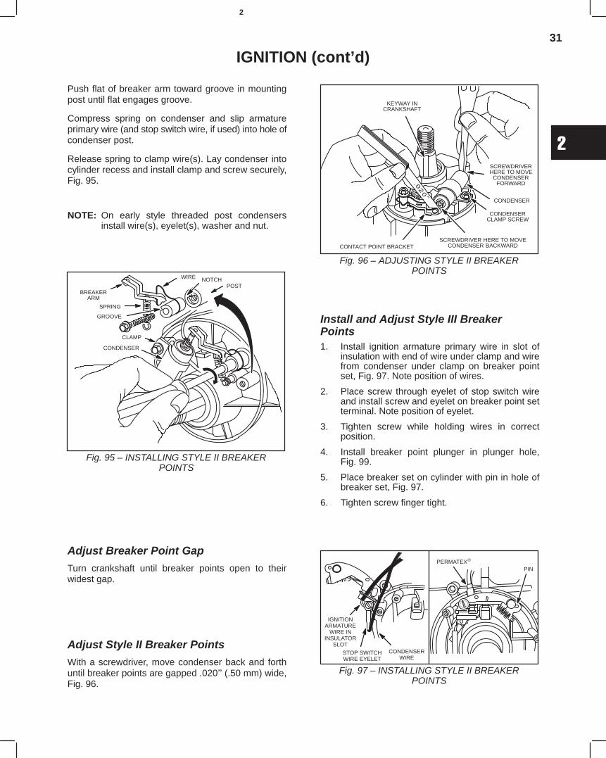
31
2
IGNITION (cont’d)
Push flat of breaker arm toward groove in mountingpost until flat engages groove.
Compress spring on condenser and slip armatureprimary wire (and stop switch wire, if used) into hole ofcondenser post.
Release spring to clamp wire(s). Lay condenser intocylinder recess and install clamp and screw securely,Fig. 95.
NOTE: On early style threaded post condensersinstall wire(s), eyelet(s), washer and nut.
BREAKERARM
SPRING
GROOVE
CONDENSER
POST
CLAMP
Fig. 95 – INSTALLING STYLE II BREAKERPOINTS
WIRE NOTCH
Adjust Breaker Point Gap
Turn crankshaft until breaker points open to theirwidest gap.
Adjust Style II Breaker Points
With a screwdriver, move condenser back and forthuntil breaker points are gapped .020(.50 mm) wide,Fig. 96.
SCREWDRIVER HERE TO MOVECONDENSER BACKWARD
SCREWDRIVERHERE TO MOVE
CONDENSERFORWARD
CONDENSER
CONTACT POINT BRACKET
KEYWAY INCRANKSHAFT
CONDENSERCLAMP SCREW
Fig. 96 – ADJUSTING STYLE II BREAKERPOINTS
Install and Adjust Style III BreakerPoints1. Install ignition armature primary wire in slot of
insulation with end of wire under clamp and wirefrom condenser under clamp on breaker pointset, Fig. 97. Note position of wires.
2. Place screw through eyelet of stop switch wireand install screw and eyelet on breaker point setterminal. Note position of eyelet.
3. Tighten screw while holding wires in correctposition.
4. Install breaker point plunger in plunger hole,Fig. 99.
5. Place breaker set on cylinder with pin in hole ofbreaker set, Fig. 97.
6. Tighten screw finger tight.
IGNITIONARMATURE
WIRE ININSULATOR
SLOT
PERMATEX
PIN
STOP SWITCHWIRE EYELET
CONDENSERWIRE
Fig. 97 – INSTALLING STYLE II BREAKERPOINTS
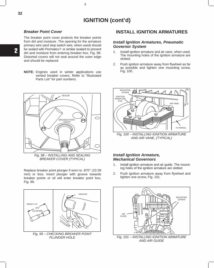
32
2
IGNITION (cont’d)
Breaker Point CoverThe breaker point cover protects the breaker pointsfrom dirt and moisture. The opening for the armatureprimary wire (and stop switch wire, when used) shouldbe sealed with Permatex or similar sealant to preventdirt and moisture from entering breaker box, Fig. 98.Distorted covers will not seal around the outer edgeand should be replaced.
NOTE: Engines used in winter applications usevented breaker covers. Refer to “IllustratedParts List” for part numbers.
SEALER
BREAKER POINTCOVER
Fig. 98 – INSTALLING AND SEALINGBREAKER COVER (TYPICAL)
Replace breaker point plunger if worn to .87022.09mm) or less. Insert plunger with groove towardsbreaker points or oil will enter breaker point box,Fig. 99.
GROOVE
REJECT AT
Fig. 99 – CHECKING BREAKER POINTPLUNGER HOLE
.870”(22.09 MM)
INSTALL IGNITION ARMATURES
Install Ignition Armatures, PneumaticGovernor System1. Install ignition armature and air vane, when used.
The mounting holes of the ignition armature areslotted.
2. Push ignition armature away from flywheel as faras possible and tighten one mounting screw,Fig. 100.
IGNITIONARMATURE
COIL
FLYWHEEL
AIR VANE
Fig. 100 – INSTALLING IGNITION ARMATUREAND AIR VANE, (TYPICAL)
MOUNTINGSCREW
Install Ignition Armature,Mechanical Governors1. Install ignition armature and air guide. The mount-
ing holes of the ignition armature are slotted.
2. Push ignition armature away from flywheel andtighten one screw, Fig. 101.
AIRGUIDE
Fig. 101 – INSTALLING IGNITION ARMATUREAND AIR GUIDE
MOUNTINGSCREW
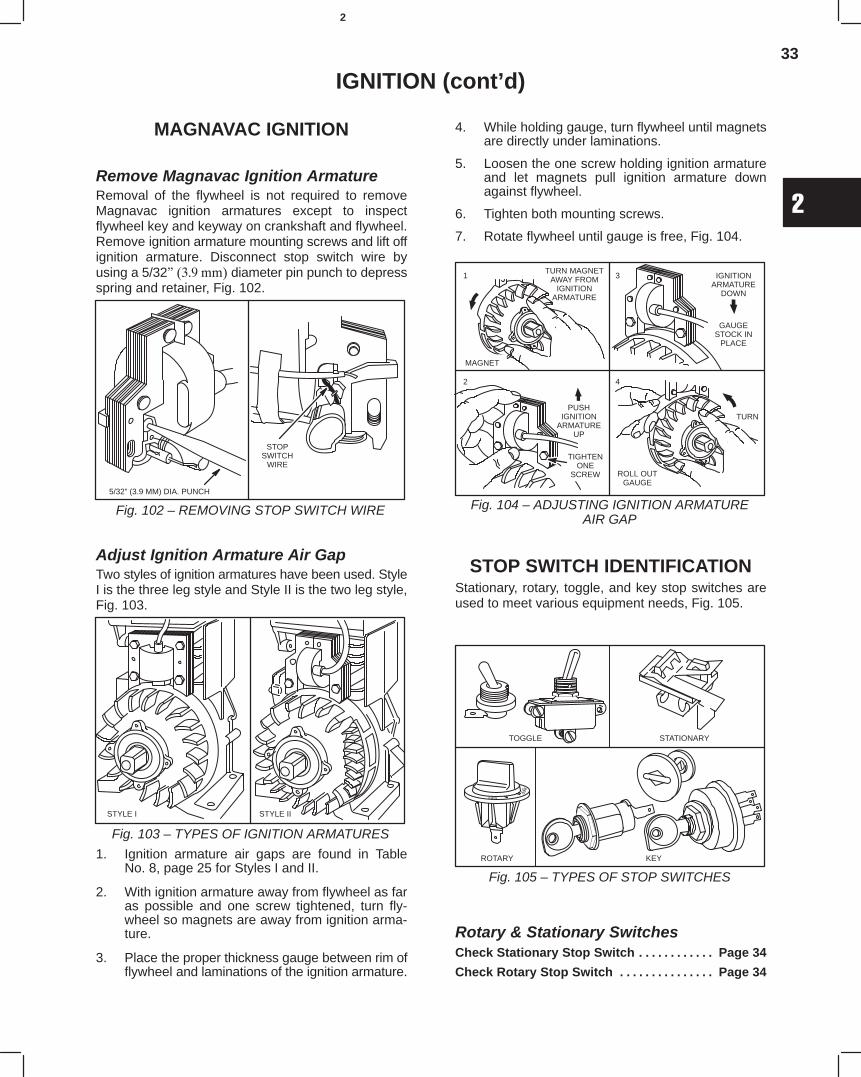
33
2
IGNITION (cont’d)
MAGNAVAC IGNITION
Remove Magnavac Ignition ArmatureRemoval of the flywheel is not required to removeMagnavac ignition armatures except to inspectflywheel key and keyway on crankshaft and flywheel.Remove ignition armature mounting screws and lift offignition armature. Disconnect stop switch wire byusing a 5/32 diameter pin punch to depressspring and retainer, Fig. 102.
5/32” (3.9 MM) DIA. PUNCH
STOPSWITCH
WIRE
Fig. 102 – REMOVING STOP SWITCH WIRE
Adjust Ignition Armature Air GapTwo styles of ignition armatures have been used. StyleI is the three leg style and Style II is the two leg style,Fig. 103.
Fig. 103 – TYPES OF IGNITION ARMATURES
STYLE I STYLE II
1. Ignition armature air gaps are found in TableNo. 8, page 25 for Styles I and II.
2. With ignition armature away from flywheel as faras possible and one screw tightened, turn fly-wheel so magnets are away from ignition arma-ture.
3. Place the proper thickness gauge between rim offlywheel and laminations of the ignition armature.
4. While holding gauge, turn flywheel until magnetsare directly under laminations.
5. Loosen the one screw holding ignition armatureand let magnets pull ignition armature downagainst flywheel.
6. Tighten both mounting screws.
7. Rotate flywheel until gauge is free, Fig. 104.
MAGNET
TURN MAGNETAWAY FROM
IGNITIONARMATURE
1
2
3
4
PUSHIGNITION
ARMATUREUP
TIGHTENONE
SCREW
IGNITIONARMATURE
DOWN
GAUGESTOCK IN
PLACE
TURN
ROLL OUTGAUGE
Fig. 104 – ADJUSTING IGNITION ARMATUREAIR GAP
STOP SWITCH IDENTIFICATIONStationary, rotary, toggle, and key stop switches areused to meet various equipment needs, Fig. 105.
TOGGLE
KEYROTARY
STATIONARY
Fig. 105 – TYPES OF STOP SWITCHES
Rotary & Stationary SwitchesCheck Stationary Stop Switch Page 34. . . . . . . . . . . .
Check Rotary Stop Switch Page 34. . . . . . . . . . . . . . .
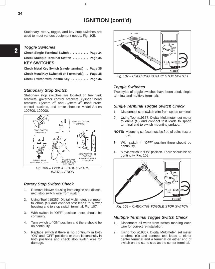
34
2
IGNITION (cont’d)
Stationary, rotary, toggle, and key stop switches areused to meet various equipment needs, Fig. 105.
Toggle SwitchesCheck Single Terminal Switch Page 34. . . . . . . . . . . .
Check Multiple Terminal Switch Page 34. . . . . . . . . .
KEY SWITCHESCheck Metal Key Switch (single terminal) Page 35. .
Check Metal Key Switch (5 or 6 terminals) Page 35. .
Check Switch with Plastic Key Page 36. . . . . . . . . . .
Stationary Stop SwitchStationary stop switches are located on fuel tankbrackets, governor control brackets, cylinder headbrackets, System 2 and System 4 band brakecontrol brackets, and brake shoe on Model Series100700, 120000.
STOP SWITCHASSEMBLY
SLOT IN CONTROLBRACKET
INSERT STOPSWITCH INTO SLOT
PUSH DOWNUNTIL IT SNAPS
INTO PLACE
STOP SWITCH INPOSITION
REVERSE STEPSTO REMOVE
Fig. 106 – TYPICAL STOP SWITCHINSTALLATION
Rotary Stop Switch Check1. Remove blower housing from engine and discon-
nect stop switch wire from switch.
2. Using Tool #19357, Digital Multimeter, set meterto ohms (Ω) and connect test leads to blowerhousing and to stop switch terminal, Fig. 107.
3. With switch in “OFF” position there should becontinuity.
4. Turn switch to “ON” position and there should beno continuity.
5. Replace switch if there is no continuity in both“ON” and “OFF” positions or there is continuity inboth positions and check stop switch wire fordamage.
Fig. 107 – CHECKING ROTARY STOP SWITCH
Toggle SwitchesTwo styles of toggle switches have been used, singleterminal and multiple terminals.
Single Terminal Toggle Switch Check1. Disconnect stop switch wire from spade terminal.
2. Using Tool #19357, Digital Multimeter, set meterto ohms (Ω) and connect test leads to spadeterminal and to switch mounting surface.
NOTE: Mounting surface must be free of paint, rust ordirt.
3. With switch in “OFF” position there should becontinuity.
4. Move switch to “ON” position. There should be nocontinuity, Fig. 108.
Fig. 108 – CHECKING TOGGLE STOP SWITCH
Multiple Terminal Toggle Switch Check1. Disconnect all wires from switch marking each
wire for correct reinstallation.
2. Using Tool #19357, Digital Multimeter, set meterto ohms (Ω) and connect test leads to eithercenter terminal and a terminal on either end ofswitch on the same side as the center terminal.
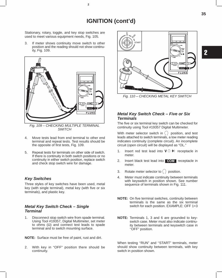
35
2
IGNITION (cont’d)
Stationary, rotary, toggle, and key stop switches areused to meet various equipment needs, Fig. 105.
3. If meter shows continuity move switch to otherposition and the reading should not show continu-ity, Fig. 109.
Fig. 109 – CHECKING MULTIPLE TERMINALSWITCH
4. Move tests lead from end terminal to other endterminal and repeat tests. Test results should bethe opposite of first tests, Fig. 109.
5. Repeat tests for terminals on other side of switch.If there is continuity in both switch positions or nocontinuity in either switch position, replace switchand check stop switch wire for damage.
Key SwitchesThree styles of key switches have been used, metalkey (with single terminal), metal key (with five or sixterminals), and plastic key.
Metal Key Switch Check – SingleTerminal
1. Disconnect stop switch wire from spade terminal.Using Tool #19357, Digital Multimeter, set meterto ohms (Ω) and connect test leads to spadeterminal and to switch mounting surface.
NOTE: Surface must be free of paint, rust and dirt.
2. With key in “OFF” position there should becontinuity.
Fig. 110 – CHECKING METAL KEY SWITCH
Metal Key Switch Check – Five or SixTerminalsThe five or six terminal key switch can be checked forcontinuity using Tool #19357 Digital Multimeter.
With meter selector switch in position, and testleads attached to switch terminals, a low meter readingindicates continuity (complete circuit). An incompletecircuit (open circuit) will be displayed as “OL.”
1. Insert red test lead into receptacle inmeter.
2. Insert black test lead into receptacle inmeter.
3. Rotate meter selector to position.
4. Meter must indicate continuity between terminalswith keyswitch in position shown. See numbersequence of terminals shown in Fig. 111.
NOTE: On five terminal switches, continuity betweenterminals is the same as the six terminalswitch for each position. EXAMPLE: OFF 1+3
NOTE: Terminals 1, 3 and 6 are grounded to key-switch case. Meter must also indicate continu-ity between terminals and keyswitch case in‘‘OFF” position.
When testing ‘‘RUN” and ‘‘START” terminals, metershould show continuity between terminals, with keyswitch in position shown.
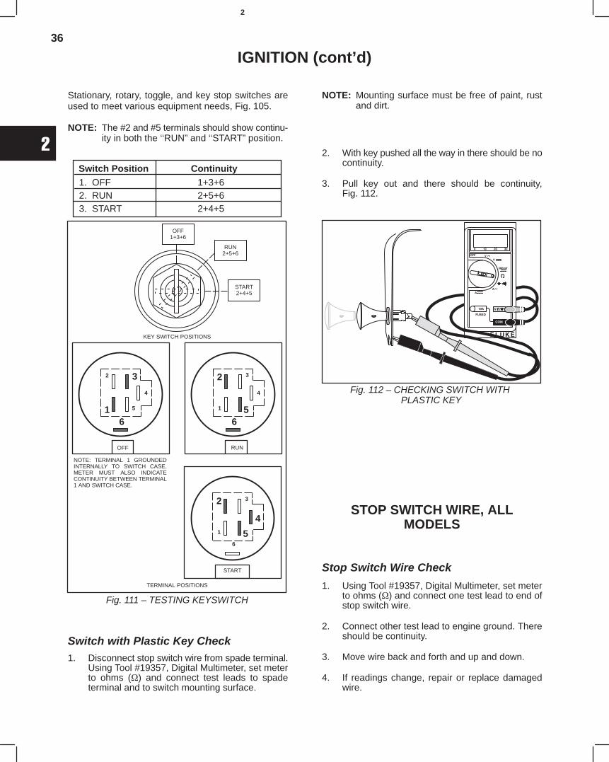
36
2
IGNITION (cont’d)
Stationary, rotary, toggle, and key stop switches areused to meet various equipment needs, Fig. 105.
NOTE: The #2 and #5 terminals should show continu-ity in both the ‘‘RUN” and ‘‘START” position.
Switch Position Continuity1. OFF 1+3+62. RUN 2+5+63. START 2+4+5
Fig. 111 – TESTING KEYSWITCH
6
5
4
32
1
TERMINAL POSITIONS
OFF
3
65
4
2
1
RUN
3
6
5
4
2
1
START
NOTE: TERMINAL 1 GROUNDEDINTERNALLY TO SWITCH CASE.METER MUST ALSO INDICATECONTINUITY BETWEEN TERMINAL1 AND SWITCH CASE.
OFF1+3+6
RUN2+5+6
START2+4+5
KEY SWITCH POSITIONS
Switch with Plastic Key Check1. Disconnect stop switch wire from spade terminal.
Using Tool #19357, Digital Multimeter, set meterto ohms (Ω) and connect test leads to spadeterminal and to switch mounting surface.
NOTE: Mounting surface must be free of paint, rustand dirt.
2. With key pushed all the way in there should be nocontinuity.
3. Pull key out and there should be continuity,Fig. 112.
Fig. 112 – CHECKING SWITCH WITH PLASTIC KEY
STOP SWITCH WIRE, ALLMODELS
Stop Switch Wire Check
1. Using Tool #19357, Digital Multimeter, set meterto ohms (Ω) and connect one test lead to end ofstop switch wire.
2. Connect other test lead to engine ground. Thereshould be continuity.
3. Move wire back and forth and up and down.
4. If readings change, repair or replace damagedwire.
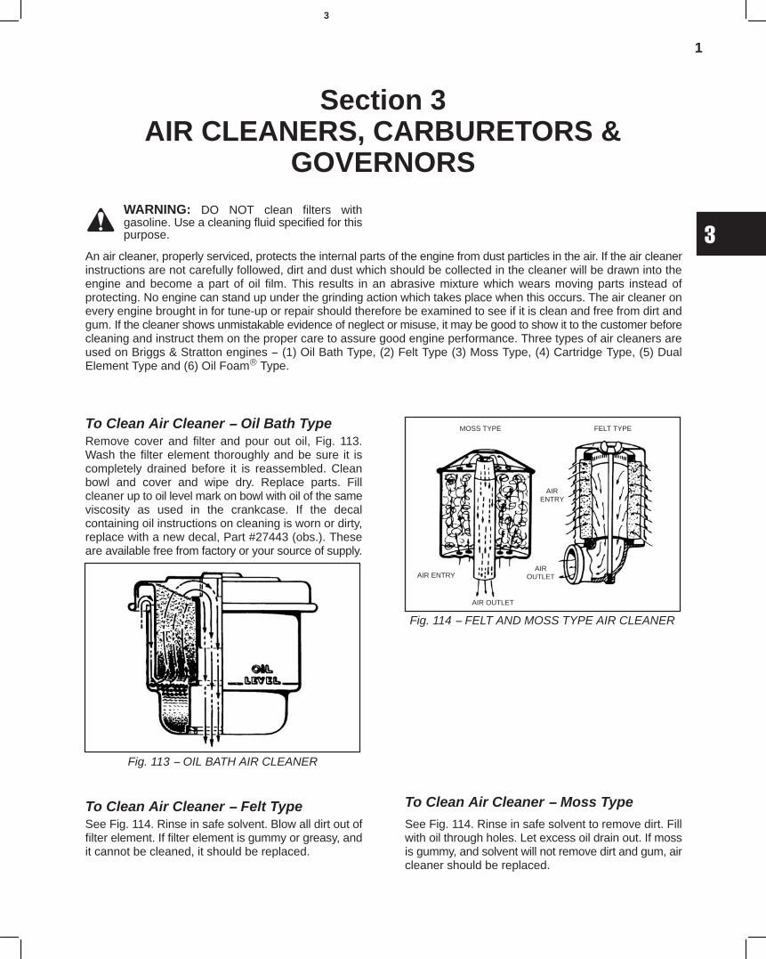
1
3
Section 3AIR CLEANERS, CARBURETORS &
GOVERNORSWARNING: DO NOT clean filters withgasoline. Use a cleaning fluid specified for thispurpose.
An air cleaner, properly serviced, protects the internal parts of the engine from dust particles in the air. If the air cleanerinstructions are not carefully followed, dirt and dust which should be collected in the cleaner will be drawn into theengine and become a part of oil film. This results in an abrasive mixture which wears moving parts instead ofprotecting. No engine can stand up under the grinding action which takes place when this occurs. The air cleaner onevery engine brought in for tune-up or repair should therefore be examined to see if it is clean and free from dirt andgum. If the cleaner shows unmistakable evidence of neglect or misuse, it may be good to show it to the customer beforecleaning and instruct them on the proper care to assure good engine performance. Three types of air cleaners areused on Briggs & Stratton engines − (1) Oil Bath Type, (2) Felt Type (3) Moss Type, (4) Cartridge Type, (5) DualElement Type and (6) Oil Foam Type.
To Clean Air Cleaner − Oil Bath TypeRemove cover and filter and pour out oil, Fig. 113.Wash the filter element thoroughly and be sure it iscompletely drained before it is reassembled. Cleanbowl and cover and wipe dry. Replace parts. Fillcleaner up to oil level mark on bowl with oil of the sameviscosity as used in the crankcase. If the decalcontaining oil instructions on cleaning is worn or dirty,replace with a new decal, Part #27443 (obs.). Theseare available free from factory or your source of supply.
Fig. 113 − OIL BATH AIR CLEANER
To Clean Air Cleaner − Felt TypeSee Fig. 114. Rinse in safe solvent. Blow all dirt out offilter element. If filter element is gummy or greasy, andit cannot be cleaned, it should be replaced.
Fig. 114 − FELT AND MOSS TYPE AIR CLEANER
MOSS TYPE FELT TYPE
AIRENTRY
AIROUTLET
AIR OUTLET
AIR ENTRY
To Clean Air Cleaner − Moss Type
See Fig. 114. Rinse in safe solvent to remove dirt. Fillwith oil through holes. Let excess oil drain out. If mossis gummy, and solvent will not remove dirt and gum, aircleaner should be replaced.
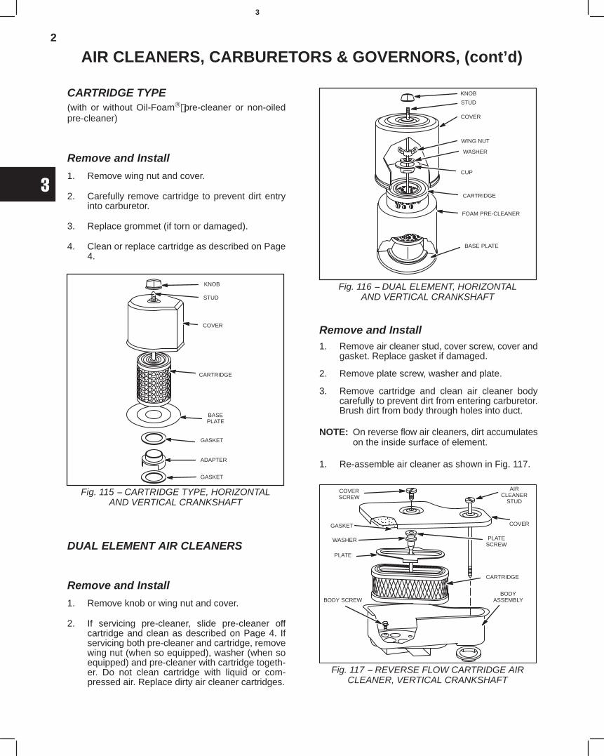
2
3
AIR CLEANERS, CARBURETORS & GOVERNORS, (cont’d)
CARTRIDGE TYPE(with or without Oil-Foam pre-cleaner or non-oiledpre-cleaner)
Remove and Install
1. Remove wing nut and cover.
2. Carefully remove cartridge to prevent dirt entryinto carburetor.
3. Replace grommet (if torn or damaged).
4. Clean or replace cartridge as described on Page4.
Fig. 115 − CARTRIDGE TYPE, HORIZONTALAND VERTICAL CRANKSHAFT
KNOB
STUD
COVER
CARTRIDGE
BASEPLATE
GASKET
ADAPTER
GASKET
DUAL ELEMENT AIR CLEANERS
Remove and Install
1. Remove knob or wing nut and cover.
2. If servicing pre-cleaner, slide pre-cleaner offcartridge and clean as described on Page 4. Ifservicing both pre-cleaner and cartridge, removewing nut (when so equipped), washer (when soequipped) and pre-cleaner with cartridge togeth-er. Do not clean cartridge with liquid or com-pressed air. Replace dirty air cleaner cartridges.
KNOB
STUD
COVER
WING NUT
WASHER
CUP
CARTRIDGE
FOAM PRE-CLEANER
BASE PLATE
Fig. 116 − DUAL ELEMENT, HORIZONTALAND VERTICAL CRANKSHAFT
Remove and Install1. Remove air cleaner stud, cover screw, cover and
gasket. Replace gasket if damaged.
2. Remove plate screw, washer and plate.
3. Remove cartridge and clean air cleaner bodycarefully to prevent dirt from entering carburetor.Brush dirt from body through holes into duct.
NOTE: On reverse flow air cleaners, dirt accumulateson the inside surface of element.
1. Re-assemble air cleaner as shown in Fig. 117.
COVERSCREW
ÎÎÎGASKET
WASHER
PLATE
BODY SCREW
AIRCLEANER
STUD
COVER
PLATESCREW
CARTRIDGE
BODYASSEMBLY
Fig. 117 − REVERSE FLOW CARTRIDGE AIRCLEANER, VERTICAL CRANKSHAFT
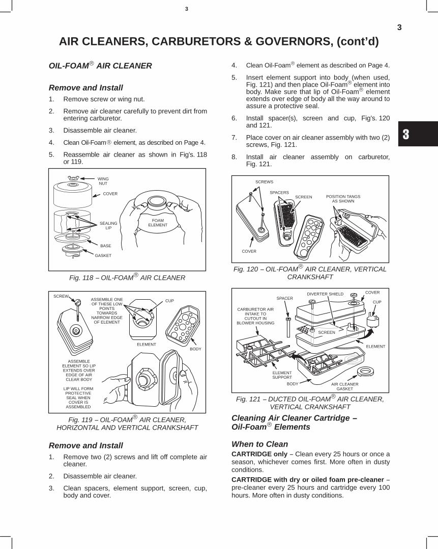
3
3
AIR CLEANERS, CARBURETORS & GOVERNORS, (cont’d)
OIL-FOAM AIR CLEANER
Remove and Install1. Remove screw or wing nut.
2. Remove air cleaner carefully to prevent dirt fromentering carburetor.
3. Disassemble air cleaner.
4. Clean Oil-Foam element, as described on Page 4.
5. Reassemble air cleaner as shown in Fig’s. 118or 119.
WINGNUT
COVER
SEALINGLIP
BASE
GASKET
FOAMELEMENT
Fig. 118 − OIL-FOAM AIR CLEANER
SCREWASSEMBLE ONEOF THESE LOW
POINTSTOWARDS
NARROW EDGEOF ELEMENT
ASSEMBLEELEMENT SO LIPEXTENDS OVER
EDGE OF AIRCLEAR BODY
LIP WILL FORMPROTECTIVESEAL WHEN
COVER ISASSEMBLED
CUP
ELEMENTBODY
Fig. 119 − OIL-FOAM AIR CLEANER,HORIZONTAL AND VERTICAL CRANKSHAFT
Remove and Install1. Remove two (2) screws and lift off complete air
cleaner.
2. Disassemble air cleaner.
3. Clean spacers, element support, screen, cup,body and cover.
4. Clean Oil-Foam element as described on Page 4.
5. Insert element support into body (when used,Fig. 121) and then place Oil-Foam element intobody. Make sure that lip of Oil-Foam elementextends over edge of body all the way around toassure a protective seal.
6. Install spacer(s), screen and cup, Fig’s. 120and 121.
7. Place cover on air cleaner assembly with two (2)screws, Fig. 121.
8. Install air cleaner assembly on carburetor,Fig. 121.
POSITION TANGSAS SHOWN
SPACERSSCREEN
SCREWS
COVER
Fig. 120 − OIL-FOAM AIR CLEANER, VERTICALCRANKSHAFT
DIVERTER SHIELD
CARBURETOR AIRINTAKE TOCUTOUT IN
BLOWER HOUSING
SPACER
COVER
CUP
ELEMENT
AIR CLEANERGASKET
ELEMENTSUPPORT
BODY
SCREEN
Fig. 121 − DUCTED OIL-FOAM AIR CLEANER,VERTICAL CRANKSHAFT
Cleaning Air Cleaner Cartridge −Oil-Foam Elements
When to CleanCARTRIDGE only − Clean every 25 hours or once aseason, whichever comes first. More often in dustyconditions.
CARTRIDGE with dry or oiled foam pre-cleaner −pre-cleaner every 25 hours and cartridge every 100hours. More often in dusty conditions.
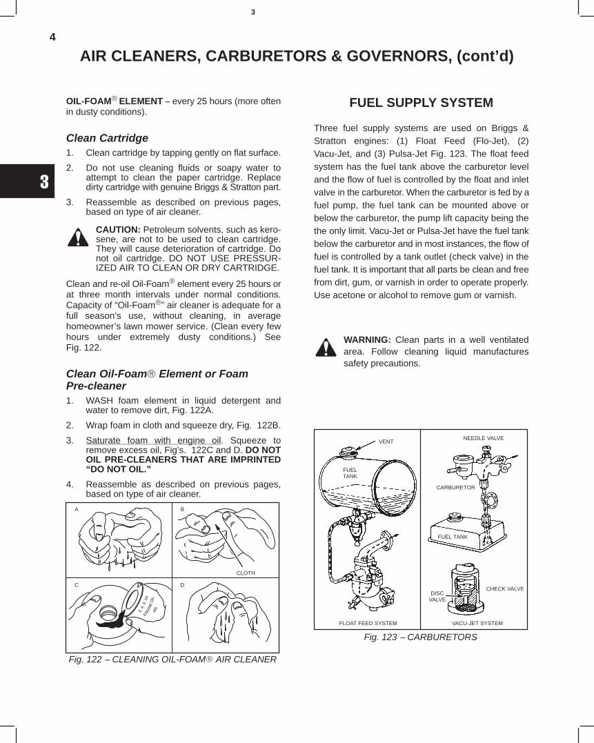
4
3
AIR CLEANERS, CARBURETORS & GOVERNORS, (cont’d)
OIL-FOAM ELEMENT − every 25 hours (more oftenin dusty conditions).
Clean Cartridge1. Clean cartridge by tapping gently on flat surface.
2. Do not use cleaning fluids or soapy water toattempt to clean the paper cartridge. Replacedirty cartridge with genuine Briggs & Stratton part.
3. Reassemble as described on previous pages,based on type of air cleaner.
CAUTION: Petroleum solvents, such as kero-sene, are not to be used to clean cartridge.They will cause deterioration of cartridge. Donot oil cartridge. DO NOT USE PRESSUR-IZED AIR TO CLEAN OR DRY CARTRIDGE.
Clean and re-oil Oil-Foam element every 25 hours orat three month intervals under normal conditions.Capacity of “Oil-Foam” air cleaner is adequate for afull season’s use, without cleaning, in averagehomeowner’s lawn mower service. (Clean every fewhours under extremely dusty conditions.) SeeFig. 122.
Clean Oil-Foam Element or FoamPre-cleaner1. WASH foam element in liquid detergent and
water to remove dirt, Fig. 122A.
2. Wrap foam in cloth and squeeze dry, Fig. 122B.
3. Saturate foam with engine oil. Squeeze toremove excess oil, Fig’s. 122C and D. DO NOTOIL PRE-CLEANERS THAT ARE IMPRINTED“DO NOT OIL.”
4. Reassemble as described on previous pages,based on type of air cleaner.
Fig. 122 − CLEANING OIL-FOAM AIR CLEANER
A
CLOTH
B
C D
FUEL SUPPLY SYSTEM
Three fuel supply systems are used on Briggs &Stratton engines: (1) Float Feed (Flo-Jet), (2)Vacu-Jet, and (3) Pulsa-Jet Fig. 123. The float feedsystem has the fuel tank above the carburetor leveland the flow of fuel is controlled by the float and inletvalve in the carburetor. When the carburetor is fed by afuel pump, the fuel tank can be mounted above orbelow the carburetor, the pump lift capacity being thethe only limit. Vacu-Jet or Pulsa-Jet have the fuel tankbelow the carburetor and in most instances, the flow offuel is controlled by a tank outlet (check valve) in thefuel tank. It is important that all parts be clean and freefrom dirt, gum, or varnish in order to operate properly.Use acetone or alcohol to remove gum or varnish.
WARNING: Clean parts in a well ventilatedarea. Follow cleaning liquid manufacturessafety precautions.
Fig. 123 − CARBURETORS
VENT
FUELTANK
FLOAT FEED SYSTEM VACU-JET SYSTEM
CHECK VALVEDISC
VALVE
FUEL TANK
CARBURETOR
NEEDLE VALVE
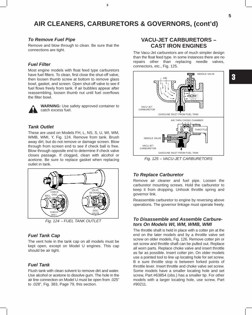
5
3
AIR CLEANERS, CARBURETORS & GOVERNORS, (cont’d)
To Remove Fuel PipeRemove and blow through to clean. Be sure that theconnections are tight.
Fuel FilterMost engine models with float feed type carburetorshave fuel filters. To clean, first close the shut-off valve,then loosen thumb screw at bottom to remove glassbowl, gasket, and screen. Open shut-off valve to see iffuel flows freely from tank. If air bubbles appear afterreassembling, loosen thumb nut until fuel overflowsthe filter bowl.
WARNING: Use safety approved container tocatch excess fuel.
Tank OutletThese are used on Models FH, L, NS, S, U, WI, WM,WMB, WMI, Y, Fig. 124. Remove from tank. Brushaway dirt, but do not remove or damage screen. Blowthrough from screen end to see if check ball is free.Blow through opposite end to determine if check valvecloses passage. If clogged, clean with alcohol oracetone. Be sure to replace gasket when replacingoutlet in tank.
Fig. 124 − FUEL TANK OUTLET
CHECKDISCBALL
CHECKBALL
VALVERETAINER
DISCVALVE
Fuel Tank CapThe vent hole in the tank cap on all models must bekept open, except on Model U engines. This capshould be air tight.
Fuel TankFlush tank with clean solvent to remove dirt and water.Use alcohol or acetone to dissolve gum. The hole in theair line connection on Model U must be open from .025”to .028”, Fig. 383, Page 79, this section.
VACU-JET CARBURETORS −CAST IRON ENGINES
The Vacu-Jet carburetors are of much simpler designthan the float feed type. In some instances there are norepairs other than replacing needle valves,connectors, etc., Fig. 125.
Fig. 125 − VACU-JET CARBURETORS
AIR
NEEDLE VALVE
VACU-JETCARBURETOR
GASOLINE INLET FROM FUEL TANK
AIR THRU CHOKE CHAMBER
VACU-JETCARBURETOR
NEEDLE VALVE
GASOLINE INLET FROM FUEL TANK
THROTTLE
To Replace CarburetorRemove air cleaner and fuel pipe. Loosen thecarburetor mounting screws. Hold the carburetor tokeep it from dropping. Unhook throttle spring andgovernor link.
Reassemble carburetor to engine by reversing aboveoperations. The governor linkage must operate freely.
To Disassemble and Assemble Carbure-tors On Models WI, WM, WMB, WMIThe throttle shaft is held in place with a cotter pin at theend on the later models and by a throttle valve setscrew on older models, Fig. 126. Remove cotter pin orset screw and throttle shaft can be pulled out. Replaceall worn parts. Replace choke valve and insert throttleas far as possible. Insert cotter pin. On older modelsuse a pointed tool to line up locating hole for set screw.B e sure throttle stop is between forked points ofthrottle lever. Insert throttle and choke valve set screw.Some models have a smaller locating hole and setscrew, Part #63854 (obs.) has a smaller tip. For othermodels with a larger locating hole, use screw, Part#90211.
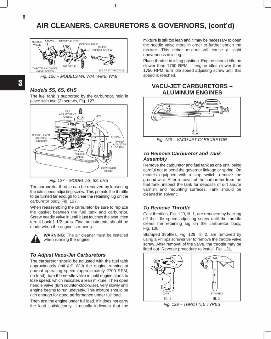
6
3
AIR CLEANERS, CARBURETORS & GOVERNORS, (cont’d)
Fig. 126 − MODELS WI, WM, WMB, WMI
NEEDLEVALVE
CHOKE THROTTLE STOPLOCATING HOLE
IDLINGADJUST SCREW
DIE CAST THROTTLE
THROTTLETHROTTLE & CHOKE
VALVE SCREW
Models 5S, 6S, 6HSThe fuel tank is supported by the carburetor, held inplace with two (2) screws, Fig. 127.
Fig. 127 − MODEL 5S, 6S, 6HS
IDLEADJUSTMENT
SCREW
CHOKE LEVER(CLOSED
POSITION)
NEEDLEVALVE
GOVERNORBLADE
SPRING
SPEEDADJUSTER
SCREW
LINK
The carburetor throttle can be removed by looseningthe idle speed adjusting screw. This permits the throttleto be turned far enough to clear the retaining lug on thecarburetor body, Fig. 127.
When reassembling the carburetor be sure to replacethe gasket between the fuel tank and carburetor.Screw needle valve in until it just touches the seat, thenturn it back 1-1/2 turns. Final adjustments should bemade when the engine is running.
WARNING: The air cleaner must be installedwhen running the engine.
To Adjust Vacu-Jet CarburetorsThe carburetor should be adjusted with the fuel tankapproximately half full. With the engine running atnormal operating speed (approximately 2700 RPM,no-load), turn the needle valve in until engine starts tolose speed, which indicates a lean mixture. Then openneedle valve (turn counter-clockwise), very slowly untilengine begins to run unevenly. This mixture should berich enough for good performance under full load.
Then test the engine under full load. If it does not carrythe load satisfactorily, it usually indicates that the
mixture is still too lean and it may be necessary to openthe needle valve more in order to further enrich themixture. This richer mixture will cause a slightunevenness in idling.
Place throttle in idling position. Engine should idle noslower than 1750 RPM. If engine idles slower than1750 RPM, turn idle speed adjusting screw until thisspeed is reached.
VACU-JET CARBURETORS −ALUMINUM ENGINES
Fig. 128 − VACU-JET CARBURETOR
To Remove Carburetor and TankAssemblyRemove the carburetor and fuel tank as one unit, beingcareful not to bend the governor linkage or spring. Onmodels equipped with a stop switch, remove theground wire. After removal of the carburetor from thefuel tank, inspect the tank for deposits of dirt and/orvarnish and mounting surfaces. Tank should becleaned in solvent.
To Remove ThrottleCast throttles, Fig. 129, Ill. 1, are removed by backingoff the idle speed adjusting screw until the throttleclears the retaining lug on the carburetor body,Fig. 130.
Stamped throttles, Fig. 129, Ill. 2, are removed byusing a Phillips screwdriver to remove the throttle valvescrew. After removal of the valve, the throttle may belifted out. Reverse procedure to install, Fig. 131.
Ill. 1 Ill. 2
Fig. 129 − THROTTLE TYPES
CAST STAMPED
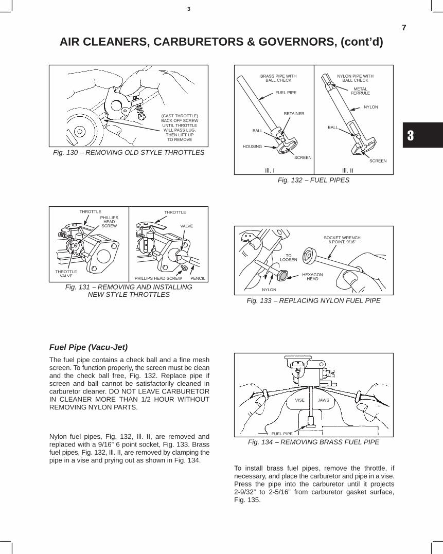
7
3
AIR CLEANERS, CARBURETORS & GOVERNORS, (cont’d)
(CAST THROTTLE)BACK OFF SCREWUNTIL THROTTLEWILL PASS LUG.THEN LIFT UPTO REMOVE
Fig. 130 − REMOVING OLD STYLE THROTTLES
Fig. 131 − REMOVING AND INSTALLINGNEW STYLE THROTTLES
THROTTLEVALVE
THROTTLEPHILLIPS
HEADSCREW VALVE
PHILLIPS HEAD SCREW PENCIL
THROTTLE
Fuel Pipe (Vacu-Jet)The fuel pipe contains a check ball and a fine meshscreen. To function properly, the screen must be cleanand the check ball free, Fig. 132. Replace pipe ifscreen and ball cannot be satisfactorily cleaned incarburetor cleaner. DO NOT LEAVE CARBURETORIN CLEANER MORE THAN 1/2 HOUR WITHOUTREMOVING NYLON PARTS.
Nylon fuel pipes, Fig. 132, Ill. II, are removed andreplaced with a 9/16” 6 point socket, Fig. 133. Brassfuel pipes, Fig. 132, Ill. II, are removed by clamping thepipe in a vise and prying out as shown in Fig. 134.
Fig. 132 − FUEL PIPESIll. I Ill. II
BRASS PIPE WITHBALL CHECK
NYLON PIPE WITHBALL CHECK
FUEL PIPE
RETAINER
HOUSING
BALL
SCREEN
METALFERRULE
NYLON
BALL
SCREEN
Fig. 133 − REPLACING NYLON FUEL PIPE
SOCKET WRENCH6 POINT, 9/16”
NYLON
TOLOOSEN
HEXAGONHEAD
Fig. 134 − REMOVING BRASS FUEL PIPE
VISE JAWS
FUEL PIPE
To install brass fuel pipes, remove the throttle, ifnecessary, and place the carburetor and pipe in a vise.Press the pipe into the carburetor until it projects2-9/32” to 2-5/16” from carburetor gasket surface,Fig. 135.
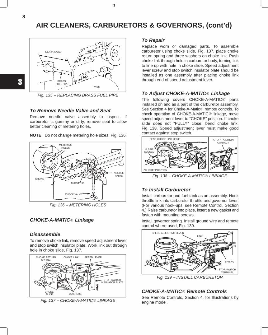
8
3
AIR CLEANERS, CARBURETORS & GOVERNORS, (cont’d)
Fig. 135 − REPLACING BRASS FUEL PIPE
2-9/32”-2-5/16”
BRASS FUEL PIPE
VISE
To Remove Needle Valve and SeatRemove needle valve assembly to inspect. Ifcarburetor is gummy or dirty, remove seat to allowbetter cleaning of metering holes.
NOTE: Do not change metering hole sizes, Fig. 136.
Fig. 136 − METERING HOLES
METERINGHOLES
CHOKE
THROTTLE
CHECK VALVE
NEEDLEVALVE
CHOKE-A-MATIC Linkage
DisassembleTo remove choke link, remove speed adjustment leverand stop switch insulator plate. Work link out throughhole in choke slide, Fig. 137.
Fig. 137 − CHOKE-A-MATIC LINKAGE
CHOKE LINK SPEED LEVERCHOKE RETURNSPRING
CHOKESLIDE WASHERS
STOP SWITCHINSULATOR PLATE
To RepairReplace worn or damaged parts. To assemblecarburetor using choke slide, Fig. 137, place chokereturn spring and three washers on choke link. Pushchoke link through hole in carburetor body, turning linkto line up with hole in choke slide. Speed adjustmentlever screw and stop switch insulator plate should beinstalled as one assembly after placing choke linkthrough end of speed adjustment lever.
To Adjust CHOKE-A-MATIC LinkageThe following covers CHOKE-A-MATIC partsinstalled on and as a part of the carburetor assembly.See Section 4 for Choke-A-Matic remote controls. Tocheck operation of CHOKE-A-MATIC linkage, movespeed adjustment lever to “CHOKE” position. If chokeslide does not “FULLY” close, bend choke link,Fig. 138. Speed adjustment lever must make goodcontact against stop switch.
Fig. 138 − CHOKE-A-MATIC LINKAGE
BEND CHOKE LINK HERE
CHOKECLOSED
“CHOKE” POSITION
“STOP” POSITIONCONTACT
To Install CarburetorInstall carburetor and fuel tank as an assembly. Hookthrottle link into carburetor throttle and governor lever.(For various hook-ups, see Remote Control, Section4.) Raise carburetor into place, insert a new gasket andfasten with mounting screws.
Install governor spring. Install ground wire and remotecontrol where used, Fig. 139.
Fig. 139 − INSTALL CARBURETOR
SPEED ADJUSTING LEVERLINK
SPRING
STOP SWITCHTERMINAL
CHOKE-A-MATIC Remote ControlsSee Remote Controls, Section 4, for Illustrations byengine model.
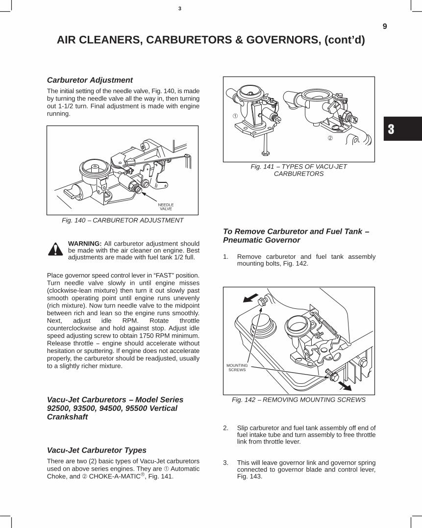
9
3
AIR CLEANERS, CARBURETORS & GOVERNORS, (cont’d)
Carburetor AdjustmentThe initial setting of the needle valve, Fig. 140, is madeby turning the needle valve all the way in, then turningout 1-1/2 turn. Final adjustment is made with enginerunning.
Fig. 140 − CARBURETOR ADJUSTMENT
NEEDLEVALVE
WARNING: All carburetor adjustment shouldbe made with the air cleaner on engine. Bestadjustments are made with fuel tank 1/2 full.
Place governor speed control lever in “FAST” position.Turn needle valve slowly in until engine misses(clockwise-lean mixture) then turn it out slowly pastsmooth operating point until engine runs unevenly(rich mixture). Now turn needle valve to the midpointbetween rich and lean so the engine runs smoothly.Next, adjust idle RPM. Rotate throttlecounterclockwise and hold against stop. Adjust idlespeed adjusting screw to obtain 1750 RPM minimum.Release throttle − engine should accelerate withouthesitation or sputtering. If engine does not accelerateproperly, the carburetor should be readjusted, usuallyto a slightly richer mixture.
Vacu-Jet Carburetors − Model Series92500, 93500, 94500, 95500 VerticalCrankshaft
Vacu-Jet Carburetor TypesThere are two (2) basic types of Vacu-Jet carburetorsused on above series engines. They are AutomaticChoke, and CHOKE-A-MATIC, Fig. 141.
Fig. 141 − TYPES OF VACU-JETCARBURETORS
To Remove Carburetor and Fuel Tank −Pneumatic Governor
1. Remove carburetor and fuel tank assemblymounting bolts, Fig. 142.
Fig. 142 − REMOVING MOUNTING SCREWS
MOUNTINGSCREWS
2. Slip carburetor and fuel tank assembly off end offuel intake tube and turn assembly to free throttlelink from throttle lever.
3. This will leave governor link and governor springconnected to governor blade and control lever,Fig. 143.
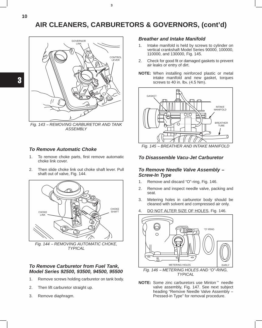
10
3
AIR CLEANERS, CARBURETORS & GOVERNORS, (cont’d)
Fig. 143 − REMOVING CARBURETOR AND TANKASSEMBLY
GOVERNORLINK
CONTROLLEVER
To Remove Automatic Choke
1. To remove choke parts, first remove automaticchoke link cover.
2. Then slide choke link out choke shaft lever. Pullshaft out of valve, Fig. 144.
Fig. 144 − REMOVING AUTOMATIC CHOKE,TYPICAL
CHOKELINK
CHOKESHAFT
To Remove Carburetor from Fuel Tank,Model Series 92500, 93500, 94500, 95500
1. Remove screws holding carburetor on tank body.
2. Then lift carburetor straight up.
3. Remove diaphragm.
Breather and Intake Manifold1. Intake manifold is held by screws to cylinder on
vertical crankshaft Model Series 90000, 100000,110000, and 130000, Fig. 145.
2. Check for good fit or damaged gaskets to preventair leaks or entry of dirt.
NOTE: When installing reinforced plastic or metalintake manifold and new gasket, torquesscrews to 40 in. lbs. (4.5 Nm).
Fig. 145 − BREATHER AND INTAKE MANIFOLD
GASKET
INTAKEMANIFOLD
BREATHERTUBE
To Disassemble Vacu-Jet Carburetor
To Remove Needle Valve Assembly −Screw-In Type1. Remove and discard “O”-ring, Fig. 146.
2. Remove and inspect needle valve, packing andseat.
3. Metering holes in carburetor body should becleaned with solvent and compressed air only.
4. DO NOT ALTER SIZE OF HOLES, Fig. 146.
METERING HOLES
“O”-RING
EARLY
Fig. 146 − METERING HOLES AND “O”-RING,TYPICAL
NOTE: Some zinc carburetors use Minlon needlevalve assembly, Fig. 147. See next subjectheading “Remove Needle Valve Assembly −Pressed-in Type” for removal procedure.
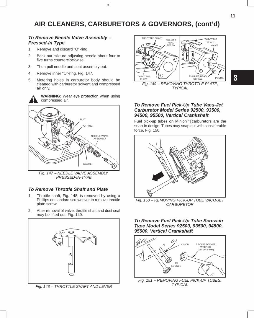
11
3
AIR CLEANERS, CARBURETORS & GOVERNORS, (cont’d)
To Remove Needle Valve Assembly −Pressed-In Type1. Remove and discard “O”-ring.
2. Back out mixture adjusting needle about four tofive turns counterclockwise.
3. Then pull needle and seat assembly out.
4. Remove inner “O”-ring, Fig. 147.
5. Metering holes in carburetor body should becleaned with carburetor solvent and compressedair only.
WARNING: Wear eye protection when usingcompressed air.
Fig. 147 − NEEDLE VALVE ASSEMBLY,PRESSED-IN-TYPE
FLAT
“O”-RING
WASHER
NEEDLE VALVEASSEMBLY
To Remove Throttle Shaft and Plate1. Throttle shaft, Fig. 148, is removed by using a
Phillips or standard screwdriver to remove throttleplate screw.
2. After removal of valve, throttle shaft and dust sealmay be lifted out, Fig. 149.
Fig. 148 − THROTTLE SHAFT AND LEVER
Fig. 149 − REMOVING THROTTLE PLATE,TYPICAL
THROTTLEPLATE
THROTTLE SHAFTPHILLIPS
HEADSCREW
THROTTLESHAFT
VALVE
PHILLIPS HEADSCREW PENCIL
To Remove Fuel Pick-Up Tube Vacu-JetCarburetor Model Series 92500, 93500,94500, 95500, Vertical CrankshaftFuel pick-up tubes on Minlon carburetors are thesnap-in design. Tubes may snap out with considerableforce, Fig. 150.
Fig. 150 − REMOVING PICK-UP TUBE VACU-JETCARBURETOR
To Remove Fuel Pick-Up Tube Screw-inType Model Series 92500, 93500, 94500,95500, Vertical Crankshaft
Fig. 151 − REMOVING FUEL PICK-UP TUBES,TYPICAL
6 POINT SOCKETWRENCH
(3/8” OR 9 MM)
NYLON
TOLOOSEN
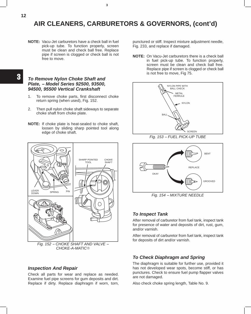
12
3
AIR CLEANERS, CARBURETORS & GOVERNORS, (cont’d)
NOTE: Vacu-Jet carburetors have a check ball in fuelpick-up tube. To function properly, screenmust be clean and check ball free. Replacepipe if screen is clogged or check ball is notfree to move.
To Remove Nylon Choke Shaft andPlate, − Model Series 92500, 93500,94500, 95500 Vertical Crankshaft
1. To remove choke parts, first disconnect chokereturn spring (when used), Fig. 152.
2. Then pull nylon choke shaft sideways to separatechoke shaft from choke plate.
NOTE: If choke plate is heat-sealed to choke shaft,loosen by sliding sharp pointed tool alongedge of choke shaft.
Fig. 152 − CHOKE SHAFT AND VALVE −CHOKE-A-MATIC
LEVERDOWN SPRING PIN
SHARP POINTEDTOOL
CHOKESHAFT
Inspection And RepairCheck all parts for wear and replace as needed.Examine fuel pipe screens for gum deposits and dirt.Replace if dirty. Replace diaphragm if worn, torn,
punctured or stiff. Inspect mixture adjustment needle,Fig. 233, and replace if damaged.
NOTE: On Vacu-Jet carburetors there is a check ballin fuel pick-up tube. To function properly,screen must be clean and check ball free.Replace pipe if screen is clogged or check ballis not free to move, Fig 75.
Fig. 153 − FUEL PICK-UP TUBE
NYLON PIPE WITHBALL CHECK
METALFERRULE
NYLON
BALL
SCREEN
Fig. 154 − MIXTURE NEEDLE
OKAY
REPLACE
BENT
GROOVED
To Inspect TankAfter removal of carburetor from fuel tank, inspect tankfor presence of water and deposits of dirt, rust, gum,and/or varnish.
After removal of carburetor from fuel tank, inspect tankfor deposits of dirt and/or varnish.
To Check Diaphragm and SpringThe diaphragm is suitable for further use, provided ithas not developed wear spots, become stiff, or haspunctures. Check to ensure fuel pump flapper valvesare not damaged.
Also check choke spring length, Table No. 9.
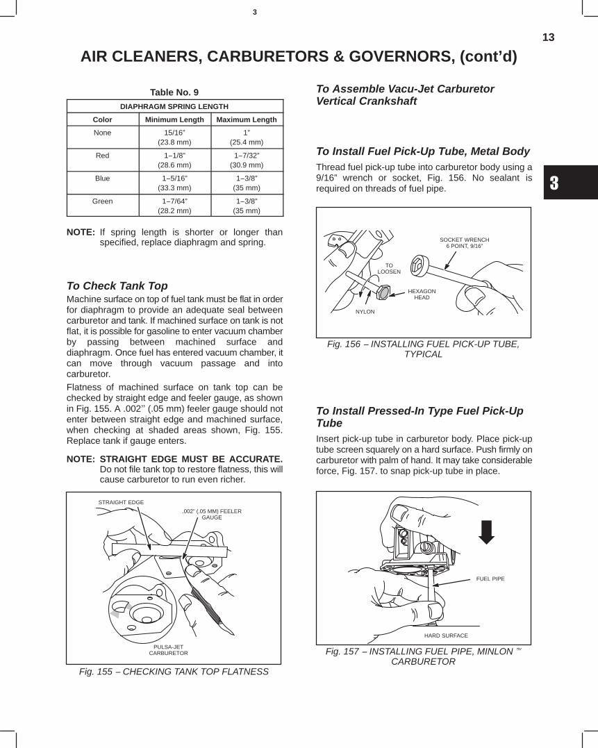
13
3
AIR CLEANERS, CARBURETORS & GOVERNORS, (cont’d)
Table No. 9DIAPHRAGM SPRING LENGTH
Color Minimum Length Maximum Length
None 15/16”(23.8 mm)
1”(25.4 mm)
Red 1−1/8”(28.6 mm)
1−7/32”(30.9 mm)
Blue 1−5/16”(33.3 mm)
1−3/8”(35 mm)
Green 1−7/64”(28.2 mm)
1−3/8”(35 mm)
NOTE: If spring length is shorter or longer thanspecified, replace diaphragm and spring.
To Check Tank TopMachine surface on top of fuel tank must be flat in orderfor diaphragm to provide an adequate seal betweencarburetor and tank. If machined surface on tank is notflat, it is possible for gasoline to enter vacuum chamberby passing between machined surface anddiaphragm. Once fuel has entered vacuum chamber, itcan move through vacuum passage and intocarburetor.Flatness of machined surface on tank top can bechecked by straight edge and feeler gauge, as shownin Fig. 155. A .002" (.05 mm) feeler gauge should notenter between straight edge and machined surface,when checking at shaded areas shown, Fig. 155.Replace tank if gauge enters.
NOTE: STRAIGHT EDGE MUST BE ACCURATE.Do not file tank top to restore flatness, this willcause carburetor to run even richer.
Fig. 155 − CHECKING TANK TOP FLATNESS
PULSA-JETCARBURETOR
STRAIGHT EDGE
.002” (.05 MM) FEELERGAUGE
To Assemble Vacu-Jet CarburetorVertical Crankshaft
To Install Fuel Pick-Up Tube, Metal BodyThread fuel pick-up tube into carburetor body using a9/16” wrench or socket, Fig. 156. No sealant isrequired on threads of fuel pipe.
Fig. 156 − INSTALLING FUEL PICK-UP TUBE,TYPICAL
SOCKET WRENCH6 POINT, 9/16”
NYLON
TOLOOSEN
HEXAGONHEAD
To Install Pressed-In Type Fuel Pick-UpTubeInsert pick-up tube in carburetor body. Place pick-uptube screen squarely on a hard surface. Push firmly oncarburetor with palm of hand. It may take considerableforce, Fig. 157. to snap pick-up tube in place.
Fig. 157 − INSTALLING FUEL PIPE, MINLON
CARBURETOR
FUEL PIPE
HARD SURFACE
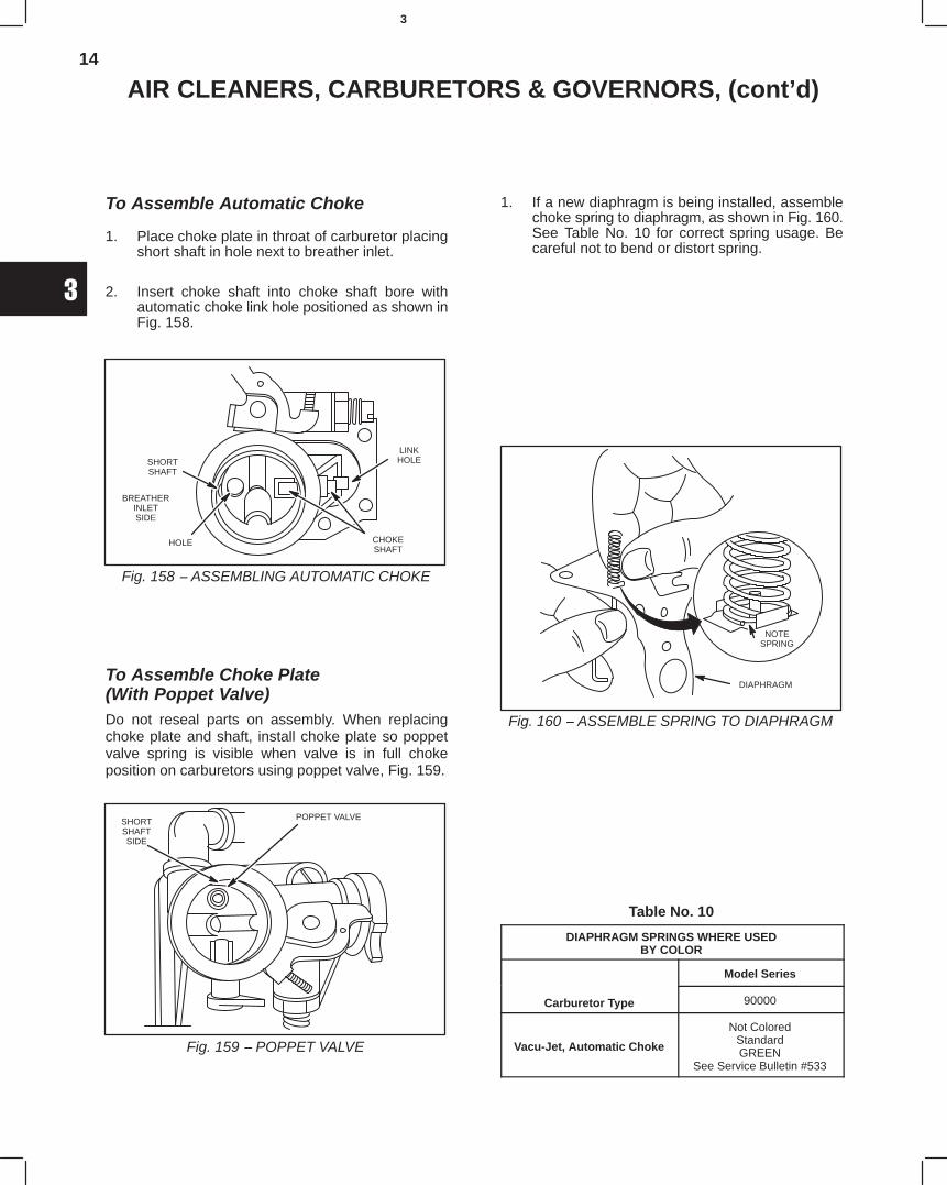
14
3
AIR CLEANERS, CARBURETORS & GOVERNORS, (cont’d)
To Assemble Automatic Choke
1. Place choke plate in throat of carburetor placingshort shaft in hole next to breather inlet.
2. Insert choke shaft into choke shaft bore withautomatic choke link hole positioned as shown inFig. 158.
Fig. 158 − ASSEMBLING AUTOMATIC CHOKE
SHORTSHAFT
HOLE CHOKESHAFT
BREATHERINLETSIDE
LINKHOLE
To Assemble Choke Plate(With Poppet Valve)Do not reseal parts on assembly. When replacingchoke plate and shaft, install choke plate so poppetvalve spring is visible when valve is in full chokeposition on carburetors using poppet valve, Fig. 159.
Fig. 159 − POPPET VALVE
POPPET VALVESHORTSHAFTSIDE
1. If a new diaphragm is being installed, assemblechoke spring to diaphragm, as shown in Fig. 160.See Table No. 10 for correct spring usage. Becareful not to bend or distort spring.
Fig. 160 − ASSEMBLE SPRING TO DIAPHRAGM
DIAPHRAGM
NOTESPRING
Table No. 10
DIAPHRAGM SPRINGS WHERE USEDBY COLOR
Model Series
Carburetor Type 90000
Vacu-Jet, Automatic Choke
Not ColoredStandardGREEN
See Service Bulletin #533
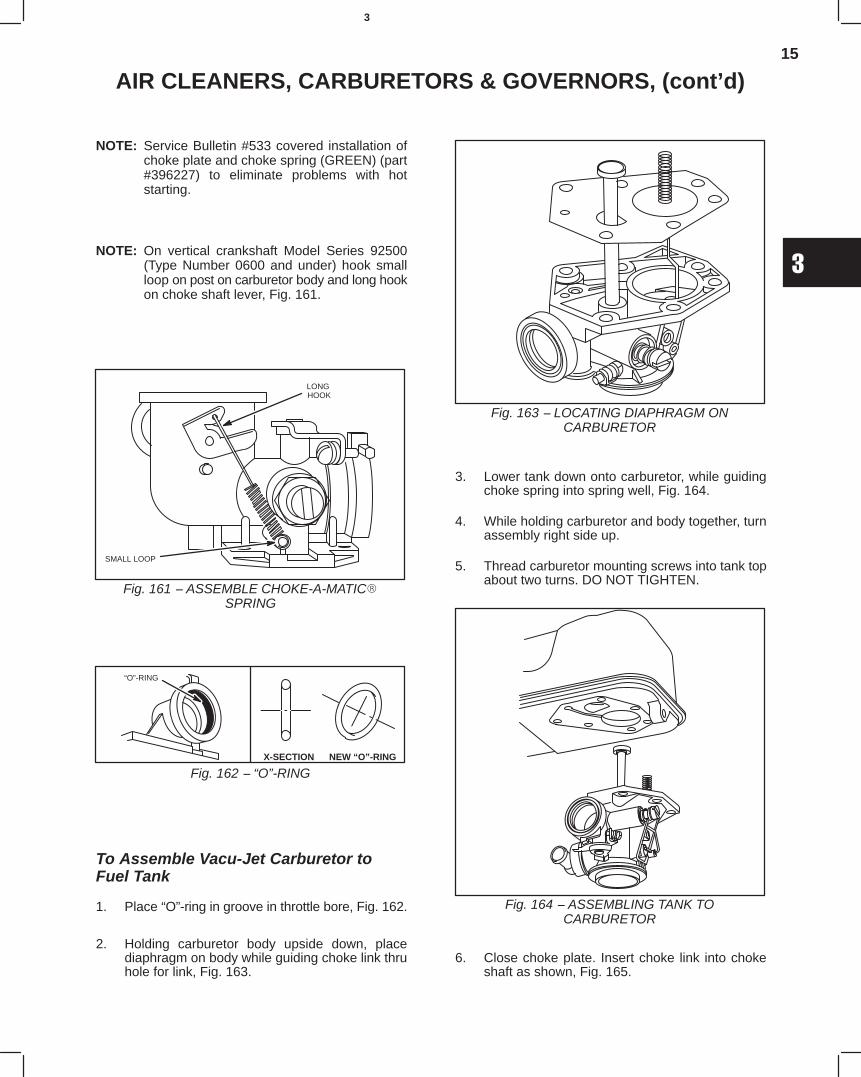
15
3
AIR CLEANERS, CARBURETORS & GOVERNORS, (cont’d)
NOTE: Service Bulletin #533 covered installation ofchoke plate and choke spring (GREEN) (part#396227) to eliminate problems with hotstarting.
NOTE: On vertical crankshaft Model Series 92500(Type Number 0600 and under) hook smallloop on post on carburetor body and long hookon choke shaft lever, Fig. 161.
Fig. 161 − ASSEMBLE CHOKE-A-MATIC
SPRING
SMALL LOOP
LONG HOOK
X-SECTION NEW “O”-RING
Fig. 162 − “O”-RING
“O”-RING
To Assemble Vacu-Jet Carburetor toFuel Tank
1. Place “O”-ring in groove in throttle bore, Fig. 162.
2. Holding carburetor body upside down, placediaphragm on body while guiding choke link thruhole for link, Fig. 163.
Fig. 163 − LOCATING DIAPHRAGM ONCARBURETOR
3. Lower tank down onto carburetor, while guidingchoke spring into spring well, Fig. 164.
4. While holding carburetor and body together, turnassembly right side up.
5. Thread carburetor mounting screws into tank topabout two turns. DO NOT TIGHTEN.
Fig. 164 − ASSEMBLING TANK TOCARBURETOR
6. Close choke plate. Insert choke link into chokeshaft as shown, Fig. 165.
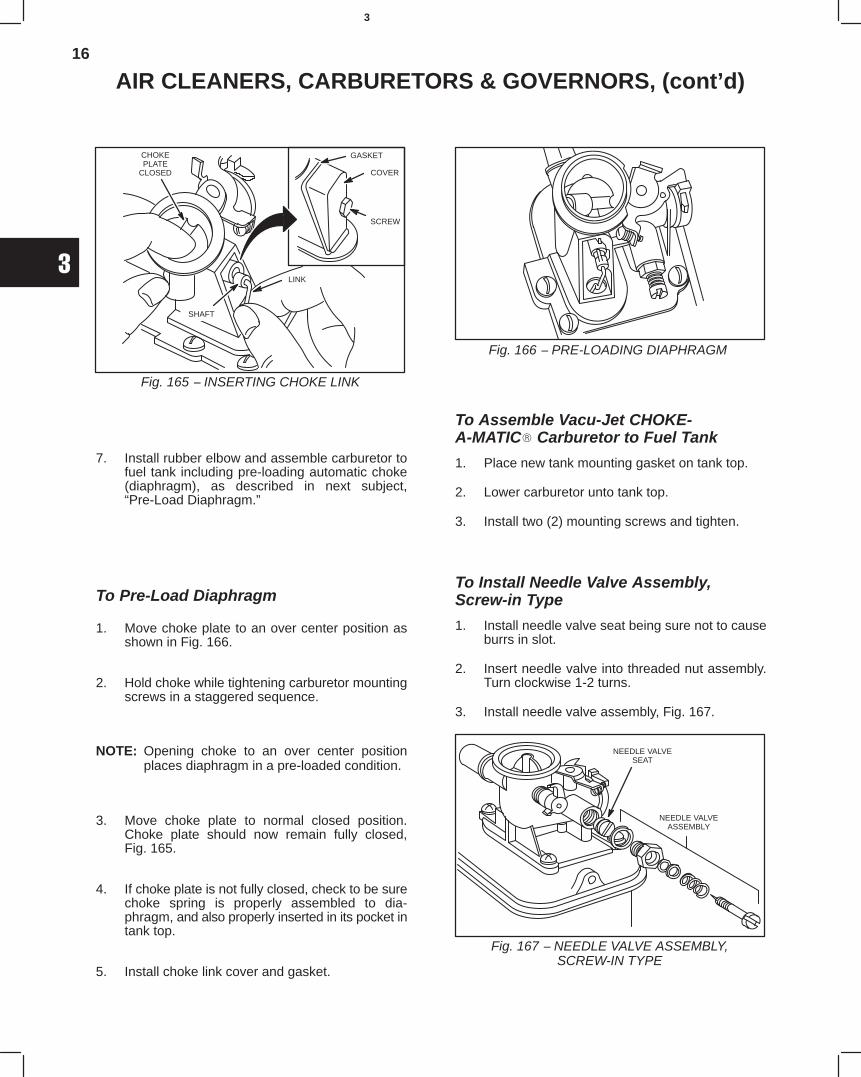
16
3
AIR CLEANERS, CARBURETORS & GOVERNORS, (cont’d)
Fig. 165 − INSERTING CHOKE LINK
GASKET
COVER
SCREW
CHOKEPLATE
CLOSED
SHAFT
LINK
7. Install rubber elbow and assemble carburetor tofuel tank including pre-loading automatic choke(diaphragm), as described in next subject,“Pre-Load Diaphragm.”
To Pre-Load Diaphragm
1. Move choke plate to an over center position asshown in Fig. 166.
2. Hold choke while tightening carburetor mountingscrews in a staggered sequence.
NOTE: Opening choke to an over center positionplaces diaphragm in a pre-loaded condition.
3. Move choke plate to normal closed position.Choke plate should now remain fully closed,Fig. 165.
4. If choke plate is not fully closed, check to be surechoke spring is properly assembled to dia-phragm, and also properly inserted in its pocket intank top.
5. Install choke link cover and gasket.
Fig. 166 − PRE-LOADING DIAPHRAGM
To Assemble Vacu-Jet CHOKE-A-MATIC Carburetor to Fuel Tank
1. Place new tank mounting gasket on tank top.
2. Lower carburetor unto tank top.
3. Install two (2) mounting screws and tighten.
To Install Needle Valve Assembly,Screw-in Type
1. Install needle valve seat being sure not to causeburrs in slot.
2. Insert needle valve into threaded nut assembly.Turn clockwise 1-2 turns.
3. Install needle valve assembly, Fig. 167.
Fig. 167 − NEEDLE VALVE ASSEMBLY,SCREW-IN TYPE
NEEDLE VALVESEAT
NEEDLE VALVEASSEMBLY
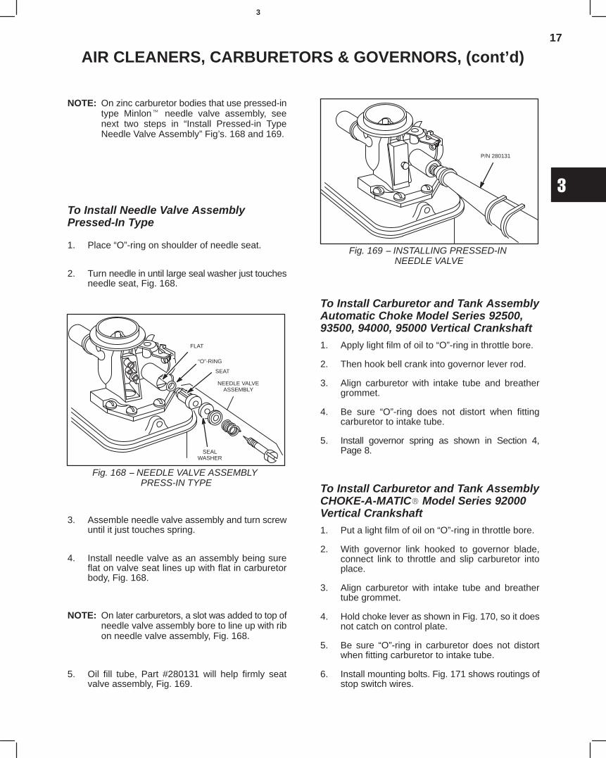
17
3
AIR CLEANERS, CARBURETORS & GOVERNORS, (cont’d)
NOTE: On zinc carburetor bodies that use pressed-intype Minlon needle valve assembly, seenext two steps in “Install Pressed-in TypeNeedle Valve Assembly” Fig’s. 168 and 169.
To Install Needle Valve AssemblyPressed-In Type
1. Place “O”-ring on shoulder of needle seat.
2. Turn needle in until large seal washer just touchesneedle seat, Fig. 168.
Fig. 168 − NEEDLE VALVE ASSEMBLY PRESS-IN TYPE
FLAT
“O”-RING
SEALWASHER
NEEDLE VALVEASSEMBLY
SEAT
3. Assemble needle valve assembly and turn screwuntil it just touches spring.
4. Install needle valve as an assembly being sureflat on valve seat lines up with flat in carburetorbody, Fig. 168.
NOTE: On later carburetors, a slot was added to top ofneedle valve assembly bore to line up with ribon needle valve assembly, Fig. 168.
5. Oil fill tube, Part #280131 will help firmly seatvalve assembly, Fig. 169.
Fig. 169 − INSTALLING PRESSED-IN NEEDLE VALVE
P/N 280131
To Install Carburetor and Tank AssemblyAutomatic Choke Model Series 92500,93500, 94000, 95000 Vertical Crankshaft1. Apply light film of oil to “O”-ring in throttle bore.
2. Then hook bell crank into governor lever rod.
3. Align carburetor with intake tube and breathergrommet.
4. Be sure “O”-ring does not distort when fittingcarburetor to intake tube.
5. Install governor spring as shown in Section 4,Page 8.
To Install Carburetor and Tank AssemblyCHOKE-A-MATIC Model Series 92000Vertical Crankshaft1. Put a light film of oil on “O”-ring in throttle bore.
2. With governor link hooked to governor blade,connect link to throttle and slip carburetor intoplace.
3. Align carburetor with intake tube and breathertube grommet.
4. Hold choke lever as shown in Fig. 170, so it doesnot catch on control plate.
5. Be sure “O”-ring in carburetor does not distortwhen fitting carburetor to intake tube.
6. Install mounting bolts. Fig. 171 shows routings ofstop switch wires.
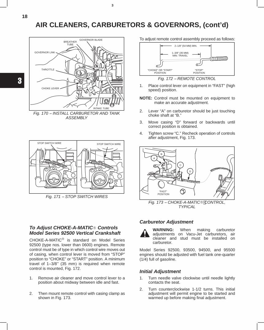
18
3
AIR CLEANERS, CARBURETORS & GOVERNORS, (cont’d)
Fig. 170 − INSTALL CARBURETOR AND TANKASSEMBLY
GOVERNOR BLADE
GOVERNOR LINK
CHOKE LEVER
THROTTLE
BREATHERTUBE
INTAKE TUBE
Fig. 171 − STOP SWITCH WIRES
STOP SWITCH WIRE STOP SWITCH WIRE
To Adjust CHOKE-A-MATIC ControlsModel Series 92500 Vertical CrankshaftCHOKE-A-MATIC is standard on Model Series92500 (type nos. lower than 0600) engines. Remotecontrol must be of type in which control wire moves outof casing, when control lever is moved from “STOP”position to “CHOKE” or “START” position. A minimumtravel of 1−3/8" (35 mm) is required when remotecontrol is mounted, Fig. 172.
1. Remove air cleaner and move control lever to aposition about midway between idle and fast.
2. Then mount remote control with casing clamp asshown in Fig. 173.
To adjust remote control assembly proceed as follows:
Fig. 172 − REMOTE CONTROL
2−1/8” (54 MM) MIN.
1−3/8” (35 MM)MIN. TRAVEL
“CHOKE” OR “START”POSITION
“STOP”POSITION
1. Place control lever on equipment in “FAST” (highspeed) position.
NOTE: Control must be mounted on equipment tomake an accurate adjustment.
2. Lever “A” on carburetor should be just touchingchoke shaft at “B.”
3. Move casing “D” forward or backwards untilcorrect position is obtained.
4. Tighten screw “C.” Recheck operation of controlsafter adjustment, Fig. 173.
Fig. 173 − CHOKE-A-MATIC CONTROL,TYPICAL
“FAST” POSITION
A
B
C
D
Carburetor Adjustment
WARNING: When making carburetoradjustments on Vacu-Jet carburetors, aircleaner and stud must be installed oncarburetor.
Model Series 92500, 93500, 94500, and 95500engines should be adjusted with fuel tank one-quarter(1/4) full of gasoline.
Initial Adjustment1. Turn needle valve clockwise until needle lightly
contacts the seat.
2. Turn counterclockwise 1-1/2 turns. This initialadjustment will permit engine to be started andwarmed up before making final adjustment.
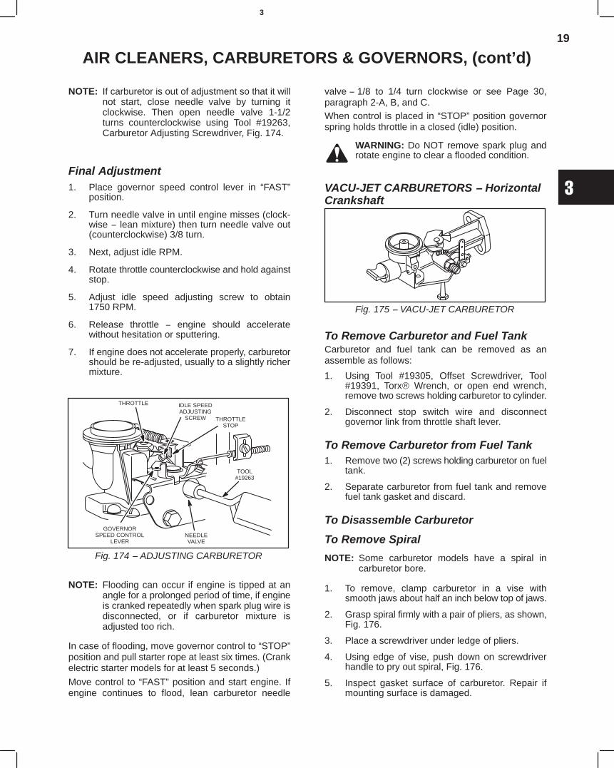
19
3
AIR CLEANERS, CARBURETORS & GOVERNORS, (cont’d)
NOTE: If carburetor is out of adjustment so that it willnot start, close needle valve by turning itclockwise. Then open needle valve 1-1/2turns counterclockwise using Tool #19263,Carburetor Adjusting Screwdriver, Fig. 174.
Final Adjustment1. Place governor speed control lever in “FAST”
position.
2. Turn needle valve in until engine misses (clock-wise − lean mixture) then turn needle valve out(counterclockwise) 3/8 turn.
3. Next, adjust idle RPM.
4. Rotate throttle counterclockwise and hold againststop.
5. Adjust idle speed adjusting screw to obtain1750 RPM.
6. Release throttle − engine should acceleratewithout hesitation or sputtering.
7. If engine does not accelerate properly, carburetorshould be re-adjusted, usually to a slightly richermixture.
Fig. 174 − ADJUSTING CARBURETOR
IDLE SPEEDADJUSTING
SCREW THROTTLESTOP
THROTTLE
GOVERNORSPEED CONTROL
LEVERNEEDLEVALVE
TOOL#19263
NOTE: Flooding can occur if engine is tipped at anangle for a prolonged period of time, if engineis cranked repeatedly when spark plug wire isdisconnected, or if carburetor mixture isadjusted too rich.
In case of flooding, move governor control to “STOP”position and pull starter rope at least six times. (Crankelectric starter models for at least 5 seconds.)
Move control to “FAST” position and start engine. Ifengine continues to flood, lean carburetor needle
valve − 1/8 to 1/4 turn clockwise or see Page 30,paragraph 2-A, B, and C.When control is placed in “STOP” position governorspring holds throttle in a closed (idle) position.
WARNING: Do NOT remove spark plug androtate engine to clear a flooded condition.
VACU-JET CARBURETORS − HorizontalCrankshaft
Fig. 175 − VACU-JET CARBURETOR
To Remove Carburetor and Fuel TankCarburetor and fuel tank can be removed as anassemble as follows:
1. Using Tool #19305, Offset Screwdriver, Tool#19391, Torx Wrench, or open end wrench,remove two screws holding carburetor to cylinder.
2. Disconnect stop switch wire and disconnectgovernor link from throttle shaft lever.
To Remove Carburetor from Fuel Tank1. Remove two (2) screws holding carburetor on fuel
tank.
2. Separate carburetor from fuel tank and removefuel tank gasket and discard.
To Disassemble Carburetor
To Remove Spiral
NOTE: Some carburetor models have a spiral incarburetor bore.
1. To remove, clamp carburetor in a vise withsmooth jaws about half an inch below top of jaws.
2. Grasp spiral firmly with a pair of pliers, as shown,Fig. 176.
3. Place a screwdriver under ledge of pliers.
4. Using edge of vise, push down on screwdriverhandle to pry out spiral, Fig. 176.
5. Inspect gasket surface of carburetor. Repair ifmounting surface is damaged.
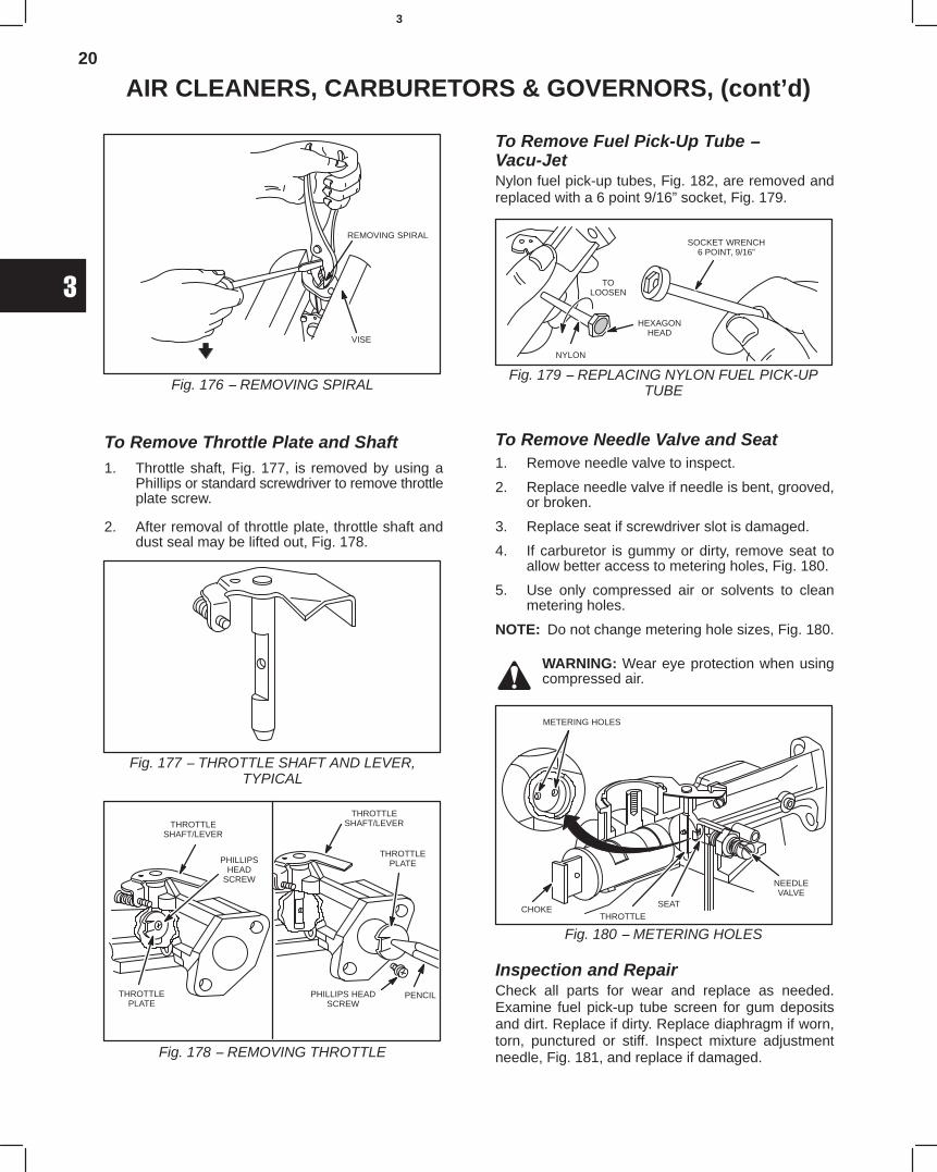
20
3
AIR CLEANERS, CARBURETORS & GOVERNORS, (cont’d)
Fig. 176 − REMOVING SPIRAL
VISE
REMOVING SPIRAL
To Remove Throttle Plate and Shaft1. Throttle shaft, Fig. 177, is removed by using a
Phillips or standard screwdriver to remove throttleplate screw.
2. After removal of throttle plate, throttle shaft anddust seal may be lifted out, Fig. 178.
Fig. 177 − THROTTLE SHAFT AND LEVER,TYPICAL
Fig. 178 − REMOVING THROTTLE
THROTTLEPLATE
THROTTLESHAFT/LEVER
PHILLIPSHEAD
SCREW
THROTTLESHAFT/LEVER
THROTTLEPLATE
PHILLIPS HEADSCREW
PENCIL
To Remove Fuel Pick-Up Tube −Vacu-JetNylon fuel pick-up tubes, Fig. 182, are removed andreplaced with a 6 point 9/16” socket, Fig. 179.
Fig. 179 − REPLACING NYLON FUEL PICK-UPTUBE
SOCKET WRENCH6 POINT, 9/16”
NYLON
TOLOOSEN
HEXAGONHEAD
To Remove Needle Valve and Seat1. Remove needle valve to inspect.
2. Replace needle valve if needle is bent, grooved,or broken.
3. Replace seat if screwdriver slot is damaged.
4. If carburetor is gummy or dirty, remove seat toallow better access to metering holes, Fig. 180.
5. Use only compressed air or solvents to cleanmetering holes.
NOTE: Do not change metering hole sizes, Fig. 180.
WARNING: Wear eye protection when usingcompressed air.
Fig. 180 − METERING HOLES
METERING HOLES
CHOKETHROTTLE
NEEDLEVALVE
SEAT
Inspection and RepairCheck all parts for wear and replace as needed.Examine fuel pick-up tube screen for gum depositsand dirt. Replace if dirty. Replace diaphragm if worn,torn, punctured or stiff. Inspect mixture adjustmentneedle, Fig. 181, and replace if damaged.
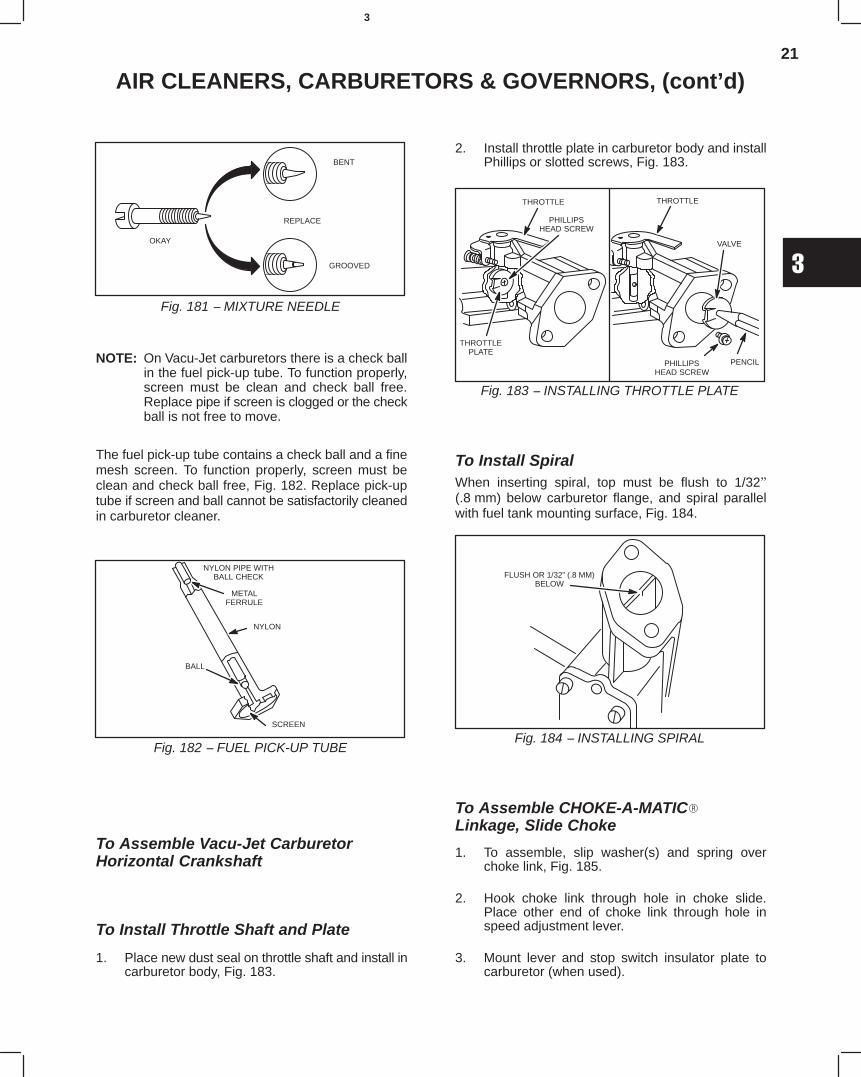
21
3
AIR CLEANERS, CARBURETORS & GOVERNORS, (cont’d)
Fig. 181 − MIXTURE NEEDLE
OKAY
REPLACE
BENT
GROOVED
NOTE: On Vacu-Jet carburetors there is a check ballin the fuel pick-up tube. To function properly,screen must be clean and check ball free.Replace pipe if screen is clogged or the checkball is not free to move.
The fuel pick-up tube contains a check ball and a finemesh screen. To function properly, screen must beclean and check ball free, Fig. 182. Replace pick-uptube if screen and ball cannot be satisfactorily cleanedin carburetor cleaner.
NYLON PIPE WITHBALL CHECK
METALFERRULE
NYLON
BALL
SCREEN
Fig. 182 − FUEL PICK-UP TUBE
To Assemble Vacu-Jet CarburetorHorizontal Crankshaft
To Install Throttle Shaft and Plate
1. Place new dust seal on throttle shaft and install incarburetor body, Fig. 183.
2. Install throttle plate in carburetor body and installPhillips or slotted screws, Fig. 183.
Fig. 183 − INSTALLING THROTTLE PLATE
THROTTLEPLATE
THROTTLE
PHILLIPSHEAD SCREW
THROTTLE
VALVE
PHILLIPSHEAD SCREW
PENCIL
To Install SpiralWhen inserting spiral, top must be flush to 1/32"(.8 mm) below carburetor flange, and spiral parallelwith fuel tank mounting surface, Fig. 184.
Fig. 184 − INSTALLING SPIRAL
FLUSH OR 1/32” (.8 MM)BELOW
To Assemble CHOKE-A-MATIC
Linkage, Slide Choke
1. To assemble, slip washer(s) and spring overchoke link, Fig. 185.
2. Hook choke link through hole in choke slide.Place other end of choke link through hole inspeed adjustment lever.
3. Mount lever and stop switch insulator plate tocarburetor (when used).
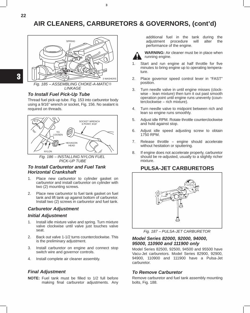
22
3
AIR CLEANERS, CARBURETORS & GOVERNORS, (cont’d)
Fig. 185 − ASSEMBLING CHOKE-A-MATIC
LINKAGE
SPRING
3 WASHERS
To Install Fuel Pick-Up TubeThread fuel pick-up tube. Fig. 153 into carburetor bodyusing a 9/16” wrench or socket, Fig. 156. No sealant isrequired on threads.
Fig. 186 − INSTALLING NYLON FUEL PICK-UP TUBE
SOCKET WRENCH6 POINT, 9/16”
NYLON
TOLOOSEN
HEXAGONHEAD
To Install Carburetor and Fuel TankHorizontal Crankshaft1. Place new carburetor to cylinder gasket on
carburetor and install carburetor on cylinder withtwo (2) mounting screws.
2. Place new carburetor to fuel tank gasket on fueltank and lift tank up against bottom of carburetor.Install two (2) screws in carburetor and fuel tank.
Carburetor AdjustmentInitial Adjustment1. Install idle mixture valve and spring. Turn mixture
valve clockwise until valve just touches valveseat.
2. Back out valve 1-1/2 turns counterclockwise. Thisis the preliminary adjustment.
3. Install carburetor on engine and connect stopswitch wire and governor controls.
4. Install complete air cleaner assembly.
Final AdjustmentNOTE: Fuel tank must be filled to 1/2 full before
making final carburetor adjustments. Any
additional fuel in the tank during theadjustment procedure will alter theperformance of the engine.
WARNING: Air cleaner must be in place whenrunning engine.
1. Start and run engine at half throttle for fiveminutes to bring engine up to operating tempera-ture.
2. Place governor speed control lever in “FAST”position.
3. Turn needle valve in until engine misses (clock-wise − lean mixture) then turn it out past smoothoperation point until engine runs unevenly (coun-terclockwise − rich mixture).
4. Turn needle valve to midpoint between rich andlean so engine runs smoothly.
5. Adjust idle RPM. Rotate throttle counterclockwiseand hold against stop.
6. Adjust idle speed adjusting screw to obtain1750 RPM.
7. Release throttle − engine should acceleratewithout hesitation or sputtering.
8. If engine does not accelerate properly, carburetorshould be re-adjusted, usually to a slightly richermixture.
PULSA-JET CARBURETORS
Fig. 187 − PULSA-JET CARBURETOR
Model Series 82000, 92000, 94000,95000, 110900 and 111900 onlyModel Series 82500, 92500, 94500 and 95500 haveVacu-Jet carburetors. Model Series 82900, 92900,94900, 110900 and 111900 have a Pulsa-Jetcarburetor.
To Remove CarburetorRemove carburetor and fuel tank assembly mountingbolts, Fig. 188.
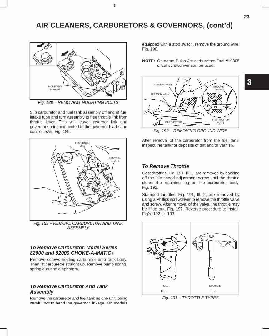
23
3
AIR CLEANERS, CARBURETORS & GOVERNORS, (cont’d)
Fig. 188 − REMOVING MOUNTING BOLTS
MOUNTINGSCREWS
Slip carburetor and fuel tank assembly off end of fuelintake tube and turn assembly to free throttle link fromthrottle lever. This will leave governor link andgovernor spring connected to the governor blade andcontrol lever, Fig. 189.
Fig. 189 − REMOVE CARBURETOR AND TANKASSEMBLY
GOVERNORLINK
CONTROLLEVER
To Remove Carburetor, Model Series82000 and 92000 CHOKE-A-MATIC
Remove screws holding carburetor onto tank body.Then lift carburetor straight up. Remove pump spring,spring cup and diaphragm.
To Remove Carburetor And TankAssemblyRemove the carburetor and fuel tank as one unit, beingcareful not to bend the governor linkage. On models
equipped with a stop switch, remove the ground wire,Fig. 190.
NOTE: On some Pulsa-Jet carburetors Tool #19305offset screwdriver can be used.
Fig. 190 − REMOVING GROUND WIRE
GROUND WIRE
PRESS TANG IN
CARBURETOR
GROUNDWIRE
STOP SWITCHPARTS
After removal of the carburetor from the fuel tank,inspect the tank for deposits of dirt and/or varnish.
To Remove ThrottleCast throttles, Fig. 191, Ill. 1, are removed by backingoff the idle speed adjustment screw until the throttleclears the retaining lug on the carburetor body,Fig. 192.
Stamped throttles, Fig. 191, Ill. 2, are removed byusing a Phillips screwdriver to remove the throttle valveand screw. After removal of the valve, the throttle maybe lifted out, Fig. 192. Reverse procedure to install,Fig’s. 192 or 193.
Fig. 191 − THROTTLE TYPES
CAST STAMPED
Ill. 1 Ill. 2
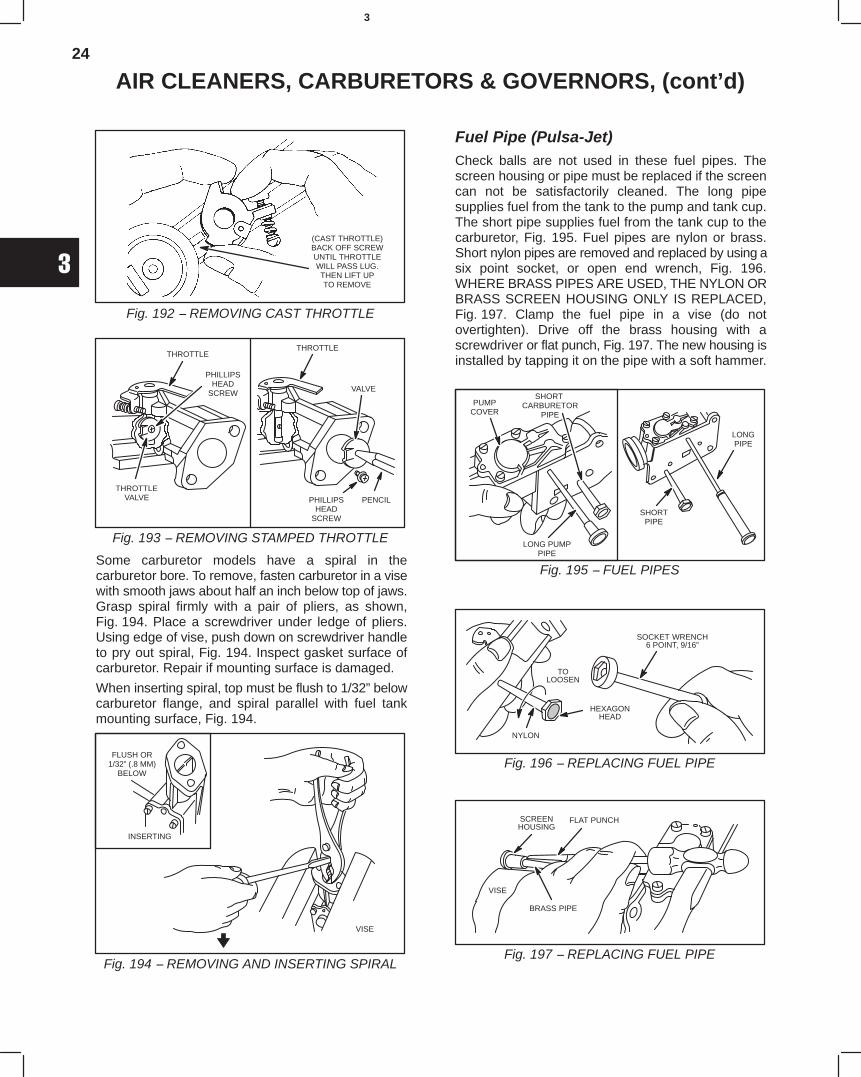
24
3
AIR CLEANERS, CARBURETORS & GOVERNORS, (cont’d)
Fig. 192 − REMOVING CAST THROTTLE
(CAST THROTTLE)BACK OFF SCREWUNTIL THROTTLEWILL PASS LUG.THEN LIFT UPTO REMOVE
Fig. 193 − REMOVING STAMPED THROTTLE
THROTTLEVALVE
THROTTLE
PHILLIPSHEAD
SCREW
THROTTLE
VALVE
PHILLIPSHEAD
SCREW
PENCIL
Some carburetor models have a spiral in thecarburetor bore. To remove, fasten carburetor in a visewith smooth jaws about half an inch below top of jaws.Grasp spiral firmly with a pair of pliers, as shown,Fig. 194. Place a screwdriver under ledge of pliers.Using edge of vise, push down on screwdriver handleto pry out spiral, Fig. 194. Inspect gasket surface ofcarburetor. Repair if mounting surface is damaged.
When inserting spiral, top must be flush to 1/32” belowcarburetor flange, and spiral parallel with fuel tankmounting surface, Fig. 194.
Fig. 194 − REMOVING AND INSERTING SPIRAL
INSERTING
FLUSH OR1/32” (.8 MM)
BELOW
VISE
Fuel Pipe (Pulsa-Jet)Check balls are not used in these fuel pipes. Thescreen housing or pipe must be replaced if the screencan not be satisfactorily cleaned. The long pipesupplies fuel from the tank to the pump and tank cup.The short pipe supplies fuel from the tank cup to thecarburetor, Fig. 195. Fuel pipes are nylon or brass.Short nylon pipes are removed and replaced by using asix point socket, or open end wrench, Fig. 196.WHERE BRASS PIPES ARE USED, THE NYLON ORBRASS SCREEN HOUSING ONLY IS REPLACED,Fig. 197. Clamp the fuel pipe in a vise (do notovertighten). Drive off the brass housing with ascrewdriver or flat punch, Fig. 197. The new housing isinstalled by tapping it on the pipe with a soft hammer.
Fig. 195 − FUEL PIPES
PUMPCOVER
SHORT CARBURETOR
PIPE
LONG PUMPPIPE
SHORTPIPE
LONGPIPE
Fig. 196 − REPLACING FUEL PIPE
SOCKET WRENCH6 POINT, 9/16”
NYLON
TOLOOSEN
HEXAGONHEAD
Fig. 197 − REPLACING FUEL PIPE
SCREENHOUSING
FLAT PUNCH
BRASS PIPE
VISE
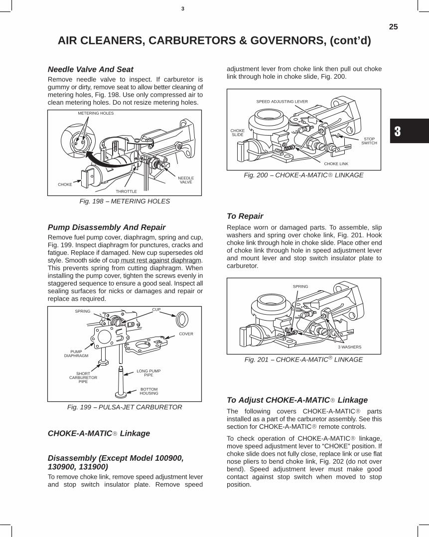
25
3
AIR CLEANERS, CARBURETORS & GOVERNORS, (cont’d)
Needle Valve And SeatRemove needle valve to inspect. If carburetor isgummy or dirty, remove seat to allow better cleaning ofmetering holes, Fig. 198. Use only compressed air toclean metering holes. Do not resize metering holes.
Fig. 198 − METERING HOLES
METERING HOLES
CHOKE
THROTTLE
NEEDLEVALVE
Pump Disassembly And RepairRemove fuel pump cover, diaphragm, spring and cup,Fig. 199. Inspect diaphragm for punctures, cracks andfatigue. Replace if damaged. New cup supersedes oldstyle. Smooth side of cup must rest against diaphragm.This prevents spring from cutting diaphragm. Wheninstalling the pump cover, tighten the screws evenly instaggered sequence to ensure a good seal. Inspect allsealing surfaces for nicks or damages and repair orreplace as required.
Fig. 199 − PULSA-JET CARBURETOR
CUP
COVER
LONG PUMPPIPE
BOTTOMHOUSING
SHORTCARBURETOR
PIPE
PUMPDIAPHRAGM
SPRING
CHOKE-A-MATIC Linkage
Disassembly (Except Model 100900,130900, 131900)To remove choke link, remove speed adjustment leverand stop switch insulator plate. Remove speed
adjustment lever from choke link then pull out chokelink through hole in choke slide, Fig. 200.
Fig. 200 − CHOKE-A-MATIC LINKAGE
SPEED ADJUSTING LEVER
STOPSWITCH
CHOKESLIDE
CHOKE LINK
To RepairReplace worn or damaged parts. To assemble, slipwashers and spring over choke link, Fig. 201. Hookchoke link through hole in choke slide. Place other endof choke link through hole in speed adjustment leverand mount lever and stop switch insulator plate tocarburetor.
Fig. 201 − CHOKE-A-MATIC LINKAGE
SPRING
3 WASHERS
To Adjust CHOKE-A-MATIC LinkageThe following covers CHOKE-A-MATIC partsinstalled as a part of the carburetor assembly. See thissection for CHOKE-A-MATIC remote controls.
To check operation of CHOKE-A-MATIC linkage,move speed adjustment lever to “CHOKE” position. Ifchoke slide does not fully close, replace link or use flatnose pliers to bend choke link, Fig. 202 (do not overbend). Speed adjustment lever must make goodcontact against stop switch when moved to stopposition.
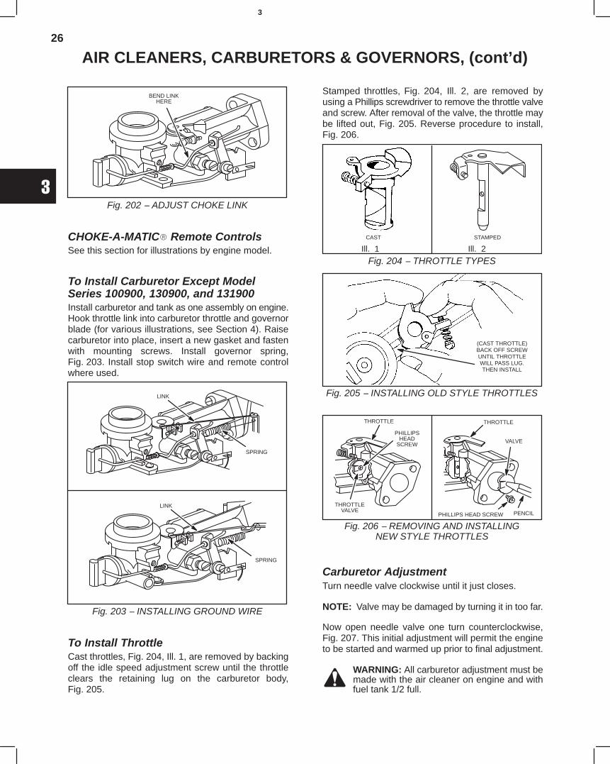
26
3
AIR CLEANERS, CARBURETORS & GOVERNORS, (cont’d)
Fig. 202 − ADJUST CHOKE LINK
BEND LINKHERE
CHOKE-A-MATIC Remote ControlsSee this section for illustrations by engine model.
To Install Carburetor Except ModelSeries 100900, 130900, and 131900Install carburetor and tank as one assembly on engine.Hook throttle link into carburetor throttle and governorblade (for various illustrations, see Section 4). Raisecarburetor into place, insert a new gasket and fastenwith mounting screws. Install governor spring,Fig. 203. Install stop switch wire and remote controlwhere used.
Fig. 203 − INSTALLING GROUND WIRE
LINK
SPRING
LINK
SPRING
To Install ThrottleCast throttles, Fig. 204, Ill. 1, are removed by backingoff the idle speed adjustment screw until the throttleclears the retaining lug on the carburetor body,Fig. 205.
Stamped throttles, Fig. 204, Ill. 2, are removed byusing a Phillips screwdriver to remove the throttle valveand screw. After removal of the valve, the throttle maybe lifted out, Fig. 205. Reverse procedure to install,Fig. 206.
Ill. 1 Ill. 2
Fig. 204 − THROTTLE TYPES
CAST STAMPED
(CAST THROTTLE)BACK OFF SCREWUNTIL THROTTLEWILL PASS LUG.THEN INSTALL
Fig. 205 − INSTALLING OLD STYLE THROTTLES
Fig. 206 − REMOVING AND INSTALLINGNEW STYLE THROTTLES
THROTTLEVALVE
THROTTLE
PHILLIPSHEAD
SCREW VALVE
PHILLIPS HEAD SCREW PENCIL
THROTTLE
Carburetor AdjustmentTurn needle valve clockwise until it just closes.
NOTE: Valve may be damaged by turning it in too far.
Now open needle valve one turn counterclockwise,Fig. 207. This initial adjustment will permit the engineto be started and warmed up prior to final adjustment.
WARNING: All carburetor adjustment must bemade with the air cleaner on engine and withfuel tank 1/2 full.
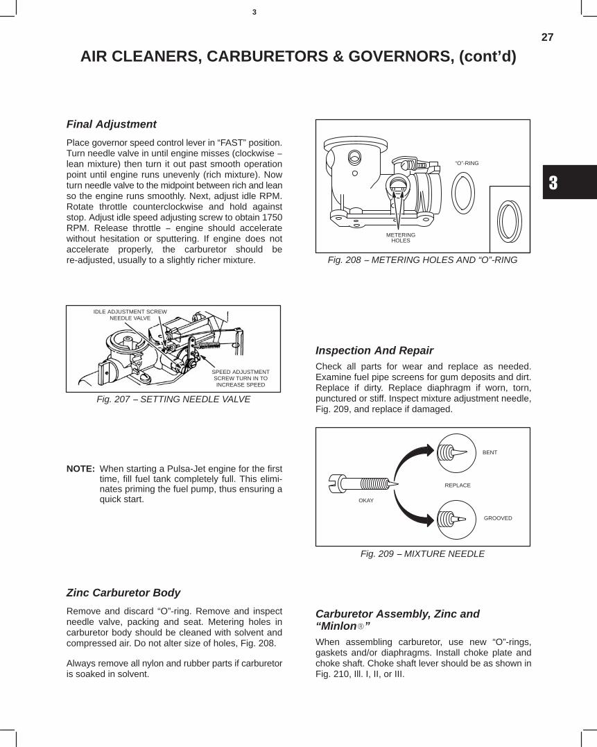
27
3
AIR CLEANERS, CARBURETORS & GOVERNORS, (cont’d)
Final Adjustment
Place governor speed control lever in “FAST” position.Turn needle valve in until engine misses (clockwise −lean mixture) then turn it out past smooth operationpoint until engine runs unevenly (rich mixture). Nowturn needle valve to the midpoint between rich and leanso the engine runs smoothly. Next, adjust idle RPM.Rotate throttle counterclockwise and hold againststop. Adjust idle speed adjusting screw to obtain 1750RPM. Release throttle − engine should acceleratewithout hesitation or sputtering. If engine does notaccelerate properly, the carburetor should bere-adjusted, usually to a slightly richer mixture.
Fig. 207 − SETTING NEEDLE VALVE
SPEED ADJUSTMENTSCREW TURN IN TOINCREASE SPEED
IDLE ADJUSTMENT SCREWNEEDLE VALVE
NOTE: When starting a Pulsa-Jet engine for the firsttime, fill fuel tank completely full. This elimi-nates priming the fuel pump, thus ensuring aquick start.
Zinc Carburetor Body
Remove and discard “O”-ring. Remove and inspectneedle valve, packing and seat. Metering holes incarburetor body should be cleaned with solvent andcompressed air. Do not alter size of holes, Fig. 208.
Always remove all nylon and rubber parts if carburetoris soaked in solvent.
Fig. 208 − METERING HOLES AND “O”-RING
METERINGHOLES
“O”-RING
Inspection And RepairCheck all parts for wear and replace as needed.Examine fuel pipe screens for gum deposits and dirt.Replace if dirty. Replace diaphragm if worn, torn,punctured or stiff. Inspect mixture adjustment needle,Fig. 209, and replace if damaged.
Fig. 209 − MIXTURE NEEDLE
OKAY
REPLACE
BENT
GROOVED
Carburetor Assembly, Zinc and“Minlon”When assembling carburetor, use new “O”-rings,gaskets and/or diaphragms. Install choke plate andchoke shaft. Choke shaft lever should be as shown inFig. 210, Ill. I, II, or III.
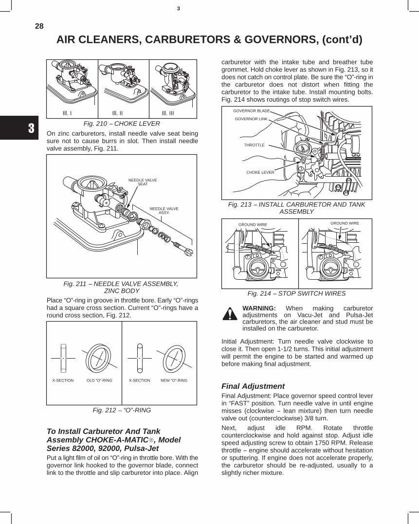
28
3
AIR CLEANERS, CARBURETORS & GOVERNORS, (cont’d)
Ill. I Ill. II Ill. III
Fig. 210 − CHOKE LEVER
On zinc carburetors, install needle valve seat beingsure not to cause burrs in slot. Then install needlevalve assembly, Fig. 211.
Fig. 211 − NEEDLE VALVE ASSEMBLY, ZINC BODY
NEEDLE VALVESEAT
NEEDLE VALVEASSY.
Place “O”-ring in groove in throttle bore. Early “O”-ringshad a square cross section. Current “O”-rings have around cross section, Fig. 212.
Fig. 212 − “O”-RING
X-SECTION OLD “O”-RING X-SECTION NEW “O”-RING
To Install Carburetor And TankAssembly CHOKE-A-MATIC, ModelSeries 82000, 92000, Pulsa-JetPut a light film of oil on “O”-ring in throttle bore. With thegovernor link hooked to the governor blade, connectlink to the throttle and slip carburetor into place. Align
carburetor with the intake tube and breather tubegrommet. Hold choke lever as shown in Fig. 213, so itdoes not catch on control plate. Be sure the “O”-ring inthe carburetor does not distort when fitting thecarburetor to the intake tube. Install mounting bolts.Fig. 214 shows routings of stop switch wires.
Fig. 213 − INSTALL CARBURETOR AND TANKASSEMBLY
GOVERNOR BLADE
GOVERNOR LINK
CHOKE LEVER
THROTTLE
Fig. 214 − STOP SWITCH WIRES
GROUND WIRE GROUND WIRE
WARNING: When making carburetoradjustments on Vacu-Jet and Pulsa-Jetcarburetors, the air cleaner and stud must beinstalled on the carburetor.
Initial Adjustment: Turn needle valve clockwise toclose it. Then open 1-1/2 turns. This initial adjustmentwill permit the engine to be started and warmed upbefore making final adjustment.
Final AdjustmentFinal Adjustment: Place governor speed control leverin “FAST” position. Turn needle valve in until enginemisses (clockwise − lean mixture) then turn needlevalve out (counterclockwise) 3/8 turn.
Next, adjust idle RPM. Rotate throttlecounterclockwise and hold against stop. Adjust idlespeed adjusting screw to obtain 1750 RPM. Releasethrottle − engine should accelerate without hesitationor sputtering. If engine does not accelerate properly,the carburetor should be re-adjusted, usually to aslightly richer mixture.
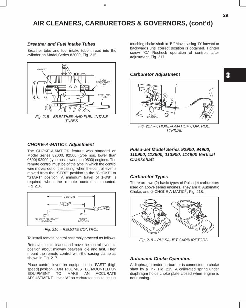
29
3
AIR CLEANERS, CARBURETORS & GOVERNORS, (cont’d)
Breather and Fuel Intake TubesBreather tube and fuel intake tube thread into thecylinder on Model Series 82000, Fig. 215.
Fig. 215 − BREATHER AND FUEL INTAKETUBES
GASKET
FUELCROSSOVER
TUBE
BREATHERTUBE
CHOKE-A-MATIC AdjustmentThe CHOKE-A-MATIC feature was standard onModel Series 82000, 92500 (type nos. lower than0600) 92900 (type nos. lower than 0500) engines. Theremote control must be of the type in which the controlwire moves out of the casing, when the control lever ismoved from the “STOP” position to the “CHOKE” or“START” position. A minimum travel of 1-3/8” isrequired when the remote control is mounted,Fig. 216.
Fig. 216 − REMOTE CONTROL
2-1/8” MIN.
1-3/8” MIN.TRAVEL
“CHOKE” OR “START”POSITION
“STOP”POSITION
To install remote control assembly proceed as follows:
Remove the air cleaner and move the control lever to aposition about midway between idle and fast. Thenmount the remote control with the casing clamp asshown in Fig. 217.
Place control lever on equipment in “FAST” (highspeed) position. CONTROL MUST BE MOUNTED ONEQUIPMENT TO MAKE AN ACCURATEADJUSTMENT. Lever “A” on carburetor should be just
touching choke shaft at “B.” Move casing “D” forward orbackwards until correct position is obtained. Tightenscrew “C.” Recheck operation of controls afteradjustment, Fig. 217.
Carburetor Adjustment
Fig. 217 − CHOKE-A-MATIC CONTROL,TYPICAL
“FAST”POSITION
AB
C
D
Pulsa-Jet Model Series 92900, 94900,110900, 112900, 113900, 114900 VerticalCrankshaft
Carburetor TypesThere are two (2) basic types of Pulsa-jet carburetorsused on above series engines. They are AutomaticChoke, and CHOKE-A-MATIC, Fig. 218.4750
Fig. 218 − PULSA-JET CARBURETORS
Automatic Choke OperationA diaphragm under carburetor is connected to chokeshaft by a link, Fig. 219. A calibrated spring underdiaphragm holds choke plate closed when engine isnot running.
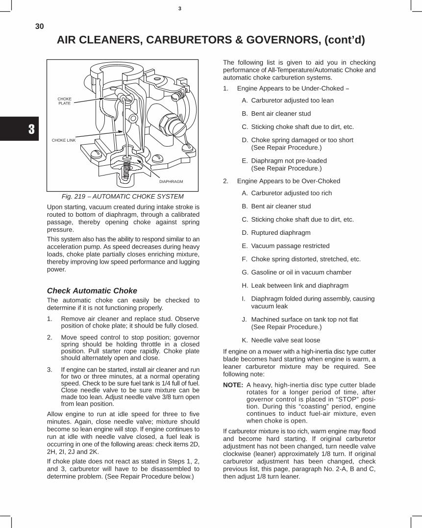
30
3
AIR CLEANERS, CARBURETORS & GOVERNORS, (cont’d)
Fig. 219 − AUTOMATIC CHOKE SYSTEM
CHOKEPLATE
CHOKE LINK
DIAPHRAGM
Upon starting, vacuum created during intake stroke isrouted to bottom of diaphragm, through a calibratedpassage, thereby opening choke against springpressure.
This system also has the ability to respond similar to anacceleration pump. As speed decreases during heavyloads, choke plate partially closes enriching mixture,thereby improving low speed performance and luggingpower.
Check Automatic ChokeThe automatic choke can easily be checked todetermine if it is not functioning properly.
1. Remove air cleaner and replace stud. Observeposition of choke plate; it should be fully closed.
2. Move speed control to stop position; governorspring should be holding throttle in a closedposition. Pull starter rope rapidly. Choke plateshould alternately open and close.
3. If engine can be started, install air cleaner and runfor two or three minutes, at a normal operatingspeed. Check to be sure fuel tank is 1/4 full of fuel.Close needle valve to be sure mixture can bemade too lean. Adjust needle valve 3/8 turn openfrom lean position.
Allow engine to run at idle speed for three to fiveminutes. Again, close needle valve; mixture shouldbecome so lean engine will stop. If engine continues torun at idle with needle valve closed, a fuel leak isoccurring in one of the following areas: check items 2D,2H, 2I, 2J and 2K.
If choke plate does not react as stated in Steps 1, 2,and 3, carburetor will have to be disassembled todetermine problem. (See Repair Procedure below.)
The following list is given to aid you in checkingperformance of All-Temperature/Automatic Choke andautomatic choke carburetion systems.
1. Engine Appears to be Under-Choked −
A. Carburetor adjusted too lean
B. Bent air cleaner stud
C. Sticking choke shaft due to dirt, etc.
D. Choke spring damaged or too short(See Repair Procedure.)
E. Diaphragm not pre-loaded(See Repair Procedure.)
2. Engine Appears to be Over-Choked
A. Carburetor adjusted too rich
B. Bent air cleaner stud
C. Sticking choke shaft due to dirt, etc.
D. Ruptured diaphragm
E. Vacuum passage restricted
F. Choke spring distorted, stretched, etc.
G. Gasoline or oil in vacuum chamber
H. Leak between link and diaphragm
I. Diaphragm folded during assembly, causing vacuum leak
J. Machined surface on tank top not flat(See Repair Procedure.)
K. Needle valve seat loose
If engine on a mower with a high-inertia disc type cutterblade becomes hard starting when engine is warm, aleaner carburetor mixture may be required. Seefollowing note:
NOTE: A heavy, high-inertia disc type cutter bladerotates for a longer period of time, aftergovernor control is placed in “STOP” posi-tion. During this “coasting” period, enginecontinues to induct fuel-air mixture, evenwhen choke is open.
If carburetor mixture is too rich, warm engine may floodand become hard starting. If original carburetoradjustment has not been changed, turn needle valveclockwise (leaner) approximately 1/8 turn. If originalcarburetor adjustment has been changed, checkprevious list, this page, paragraph No. 2-A, B and C,then adjust 1/8 turn leaner.
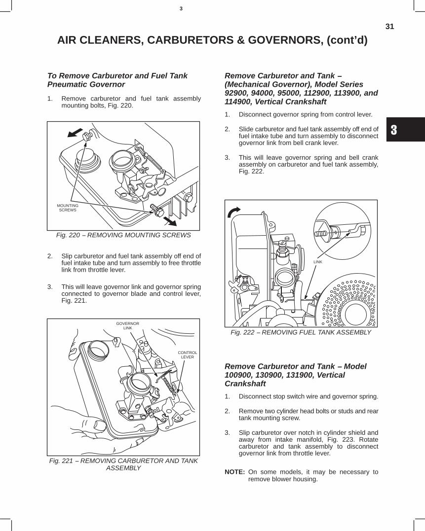
31
3
AIR CLEANERS, CARBURETORS & GOVERNORS, (cont’d)
To Remove Carburetor and Fuel TankPneumatic Governor
1. Remove carburetor and fuel tank assemblymounting bolts, Fig. 220.
Fig. 220 − REMOVING MOUNTING SCREWS
MOUNTINGSCREWS
2. Slip carburetor and fuel tank assembly off end offuel intake tube and turn assembly to free throttlelink from throttle lever.
3. This will leave governor link and governor springconnected to governor blade and control lever,Fig. 221.
Fig. 221 − REMOVING CARBURETOR AND TANKASSEMBLY
GOVERNORLINK
CONTROLLEVER
Remove Carburetor and Tank −(Mechanical Governor), Model Series92900, 94000, 95000, 112900, 113900, and114900, Vertical Crankshaft
1. Disconnect governor spring from control lever.
2. Slide carburetor and fuel tank assembly off end offuel intake tube and turn assembly to disconnectgovernor link from bell crank lever.
3. This will leave governor spring and bell crankassembly on carburetor and fuel tank assembly,Fig. 222.
Fig. 222 − REMOVING FUEL TANK ASSEMBLY
LINK
Remove Carburetor and Tank − Model100900, 130900, 131900, VerticalCrankshaft
1. Disconnect stop switch wire and governor spring.
2. Remove two cylinder head bolts or studs and reartank mounting screw.
3. Slip carburetor over notch in cylinder shield andaway from intake manifold, Fig. 223. Rotatecarburetor and tank assembly to disconnectgovernor link from throttle lever.
NOTE: On some models, it may be necessary toremove blower housing.
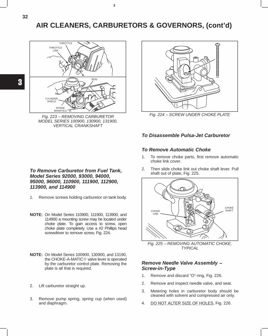
32
3
AIR CLEANERS, CARBURETORS & GOVERNORS, (cont’d)
Fig. 223 − REMOVING CARBURETORMODEL SERIES 100900, 130900, 131900,
VERTICAL CRANKSHAFT
THROTTLE
THROTTLELINK
SEAL
CYLINDERSHIELD
INTAKEMANIFOLD
To Remove Carburetor from Fuel Tank,Model Series 92000, 93000, 94000,95000, 96000, 110900, 111900, 112900,113900, and 114900
1. Remove screws holding carburetor on tank body.
NOTE: On Model Series 110900, 111900, 113900, and114900 a mounting screw may be located underchoke plate. To gain access to screw, openchoke plate completely. Use a #2 Phillips headscrewdriver to remove screw, Fig. 224.
NOTE: On Model Series 100900, 130900, and 13190,the CHOKE-A-MATIC valve lever is operatedby the carburetor control plate. Removing theplate is all that is required.
2. Lift carburetor straight up.
3. Remove pump spring, spring cup (when used)and diaphragm.
Fig. 224 − SCREW UNDER CHOKE PLATE
To Disassemble Pulsa-Jet Carburetor
To Remove Automatic Choke1. To remove choke parts, first remove automatic
choke link cover.
2. Then slide choke link out choke shaft lever. Pullshaft out of plate, Fig. 225.
Fig. 225 − REMOVING AUTOMATIC CHOKE,TYPICAL
CHOKELINK
CHOKESHAFT
Remove Needle Valve Assembly −Screw-in-Type1. Remove and discard “O”-ring, Fig. 226.
2. Remove and inspect needle valve, and seat.
3. Metering holes in carburetor body should becleaned with solvent and compressed air only.
4. DO NOT ALTER SIZE OF HOLES, Fig. 226.
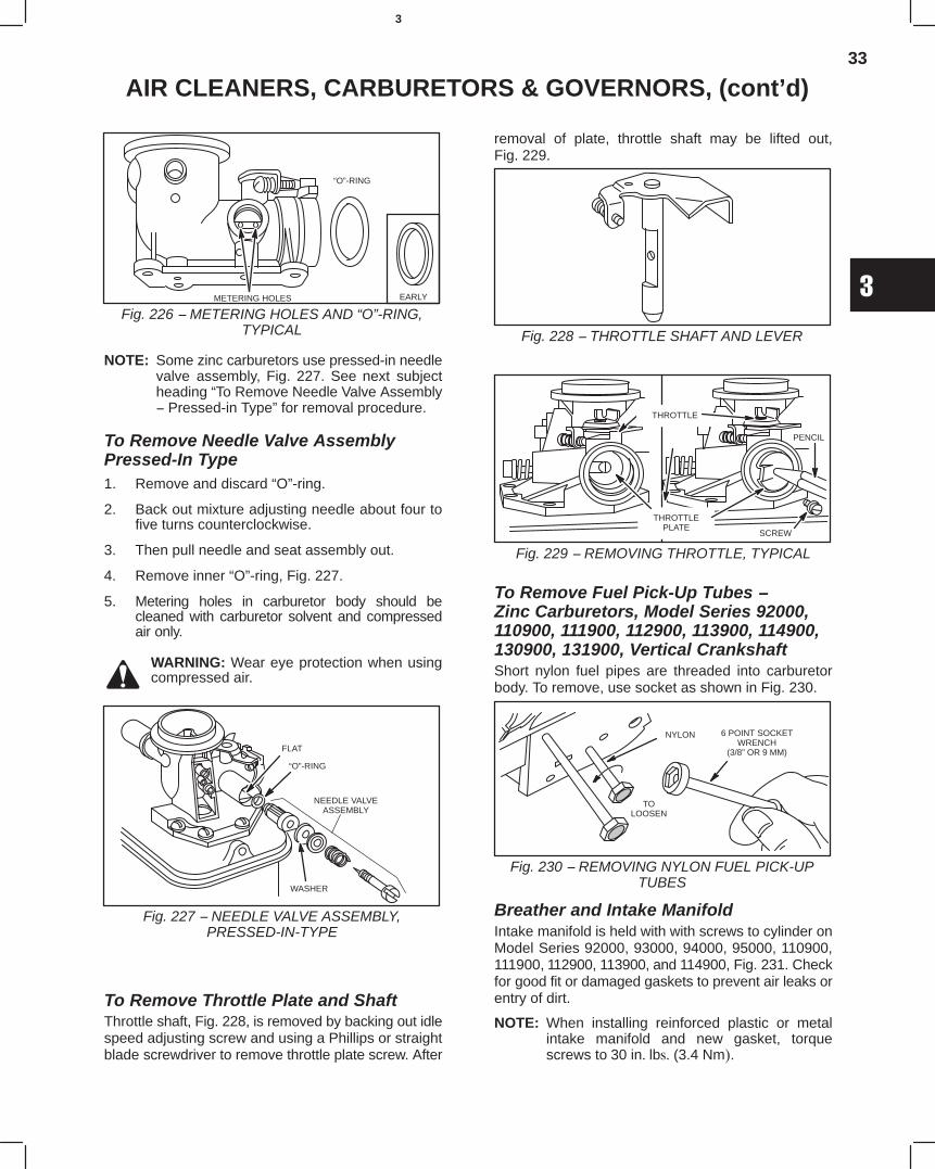
33
3
AIR CLEANERS, CARBURETORS & GOVERNORS, (cont’d)
Fig. 226 − METERING HOLES AND “O”-RING,TYPICAL
METERING HOLES
“O”-RING
EARLY
NOTE: Some zinc carburetors use pressed-in needlevalve assembly, Fig. 227. See next subjectheading “To Remove Needle Valve Assembly− Pressed-in Type” for removal procedure.
To Remove Needle Valve AssemblyPressed-In Type1. Remove and discard “O”-ring.
2. Back out mixture adjusting needle about four tofive turns counterclockwise.
3. Then pull needle and seat assembly out.
4. Remove inner “O”-ring, Fig. 227.
5. Metering holes in carburetor body should becleaned with carburetor solvent and compressedair only.
WARNING: Wear eye protection when usingcompressed air.
Fig. 227 − NEEDLE VALVE ASSEMBLY,PRESSED-IN-TYPE
FLAT
“O”-RING
WASHER
NEEDLE VALVEASSEMBLY
To Remove Throttle Plate and ShaftThrottle shaft, Fig. 228, is removed by backing out idlespeed adjusting screw and using a Phillips or straightblade screwdriver to remove throttle plate screw. After
removal of plate, throttle shaft may be lifted out,Fig. 229.
Fig. 228 − THROTTLE SHAFT AND LEVER
Fig. 229 − REMOVING THROTTLE, TYPICAL
THROTTLE
THROTTLEPLATE
SCREW
PENCIL
To Remove Fuel Pick-Up Tubes − Zinc Carburetors, Model Series 92000,110900, 111900, 112900, 113900, 114900,130900, 131900, Vertical CrankshaftShort nylon fuel pipes are threaded into carburetorbody. To remove, use socket as shown in Fig. 230.
Fig. 230 − REMOVING NYLON FUEL PICK-UPTUBES
6 POINT SOCKETWRENCH
(3/8” OR 9 MM)
NYLON
TOLOOSEN
Breather and Intake ManifoldIntake manifold is held with with screws to cylinder onModel Series 92000, 93000, 94000, 95000, 110900,111900, 112900, 113900, and 114900, Fig. 231. Checkfor good fit or damaged gaskets to prevent air leaks orentry of dirt.
NOTE: When installing reinforced plastic or metalintake manifold and new gasket, torquescrews to 30 in. lbs. (3.4 Nm).
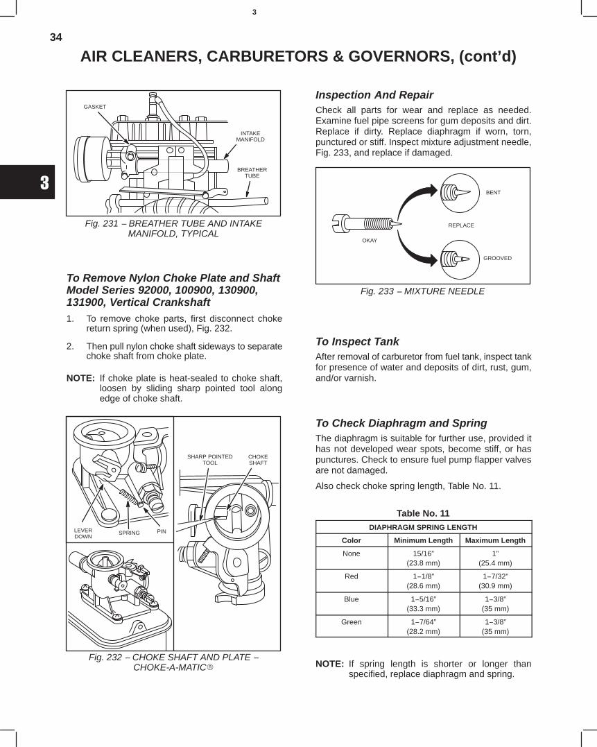
34
3
AIR CLEANERS, CARBURETORS & GOVERNORS, (cont’d)
Fig. 231 − BREATHER TUBE AND INTAKEMANIFOLD, TYPICAL
GASKET
INTAKEMANIFOLD
BREATHERTUBE
To Remove Nylon Choke Plate and ShaftModel Series 92000, 100900, 130900,131900, Vertical Crankshaft1. To remove choke parts, first disconnect choke
return spring (when used), Fig. 232.
2. Then pull nylon choke shaft sideways to separatechoke shaft from choke plate.
NOTE: If choke plate is heat-sealed to choke shaft,loosen by sliding sharp pointed tool alongedge of choke shaft.
Fig. 232 − CHOKE SHAFT AND PLATE −CHOKE-A-MATIC
LEVERDOWN
SPRING PIN
SHARP POINTEDTOOL
CHOKESHAFT
Inspection And RepairCheck all parts for wear and replace as needed.Examine fuel pipe screens for gum deposits and dirt.Replace if dirty. Replace diaphragm if worn, torn,punctured or stiff. Inspect mixture adjustment needle,Fig. 233, and replace if damaged.
Fig. 233 − MIXTURE NEEDLE
OKAY
REPLACE
BENT
GROOVED
To Inspect TankAfter removal of carburetor from fuel tank, inspect tankfor presence of water and deposits of dirt, rust, gum,and/or varnish.
To Check Diaphragm and SpringThe diaphragm is suitable for further use, provided ithas not developed wear spots, become stiff, or haspunctures. Check to ensure fuel pump flapper valvesare not damaged.
Also check choke spring length, Table No. 11.
Table No. 11DIAPHRAGM SPRING LENGTH
Color Minimum Length Maximum Length
None 15/16”(23.8 mm)
1”(25.4 mm)
Red 1−1/8”(28.6 mm)
1−7/32”(30.9 mm)
Blue 1−5/16”(33.3 mm)
1−3/8”(35 mm)
Green 1−7/64”(28.2 mm)
1−3/8”(35 mm)
NOTE: If spring length is shorter or longer thanspecified, replace diaphragm and spring.
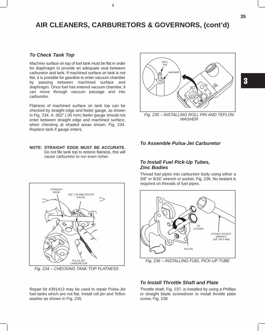
35
3
AIR CLEANERS, CARBURETORS & GOVERNORS, (cont’d)
To Check Tank Top
Machine surface on top of fuel tank must be flat in orderfor diaphragm to provide an adequate seal betweencarburetor and tank. If machined surface on tank is notflat, it is possible for gasoline to enter vacuum chamberby passing between machined surface anddiaphragm. Once fuel has entered vacuum chamber, itcan move through vacuum passage and intocarburetor.
Flatness of machined surface on tank top can bechecked by straight edge and feeler gauge, as shownin Fig. 234. A .002” (.05 mm) feeler gauge should notenter between straight edge and machined surface,when checking at shaded areas shown, Fig. 234.Replace tank if gauge enters.
NOTE: STRAIGHT EDGE MUST BE ACCURATE.Do not file tank top to restore flatness, this willcause carburetor to run even richer.
Fig. 234 − CHECKING TANK TOP FLATNESS
STRAIGHTEDGE
PULSA-JETCARBURETOR
.002” (.05 MM) FEELERGAUGE
Repair kit #391413 may be used to repair Pulsa-Jetfuel tanks which are not flat. Install roll pin and Teflonwasher as shown in Fig. 235.
Fig. 235 − INSTALLING ROLL PIN AND TEFLONWASHER
ROLLPIN
WASHER
To Assemble Pulsa-Jet Carburetor
To Install Fuel Pick-Up Tubes, Zinc BodiesThread fuel pipes into carburetor body using either a3/8” or 9/16” wrench or socket, Fig. 236. No sealant isrequired on threads of fuel pipes.
Fig. 236 − INSTALLING FUEL PICK-UP TUBE
6 POINT SOCKETWRENCH
(3/8” OR 9 MM)
NYLON
TOLOOSEN
To Install Throttle Shaft and PlateThrottle shaft, Fig. 237, is installed by using a Phillipsor straight blade screwdriver to install throttle platescrew, Fig. 238.
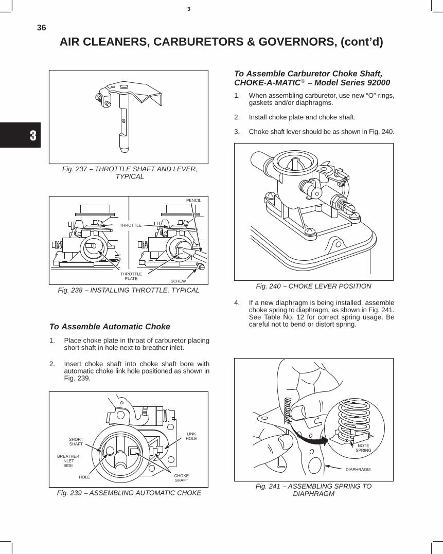
36
3
AIR CLEANERS, CARBURETORS & GOVERNORS, (cont’d)
Fig. 237 − THROTTLE SHAFT AND LEVER,TYPICAL
Fig. 238 − INSTALLING THROTTLE, TYPICAL
THROTTLE
THROTTLEPLATE
SCREW
PENCIL
To Assemble Automatic Choke
1. Place choke plate in throat of carburetor placingshort shaft in hole next to breather inlet.
2. Insert choke shaft into choke shaft bore withautomatic choke link hole positioned as shown inFig. 239.
Fig. 239 − ASSEMBLING AUTOMATIC CHOKE
SHORTSHAFT
HOLE CHOKESHAFT
BREATHERINLETSIDE
LINKHOLE
To Assemble Carburetor Choke Shaft,CHOKE-A-MATIC − Model Series 92000
1. When assembling carburetor, use new “O”-rings,gaskets and/or diaphragms.
2. Install choke plate and choke shaft.
3. Choke shaft lever should be as shown in Fig. 240.
Fig. 240 − CHOKE LEVER POSITION
4. If a new diaphragm is being installed, assemblechoke spring to diaphragm, as shown in Fig. 241.See Table No. 12 for correct spring usage. Becareful not to bend or distort spring.
Fig. 241 − ASSEMBLING SPRING TODIAPHRAGM
DIAPHRAGM
NOTESPRING
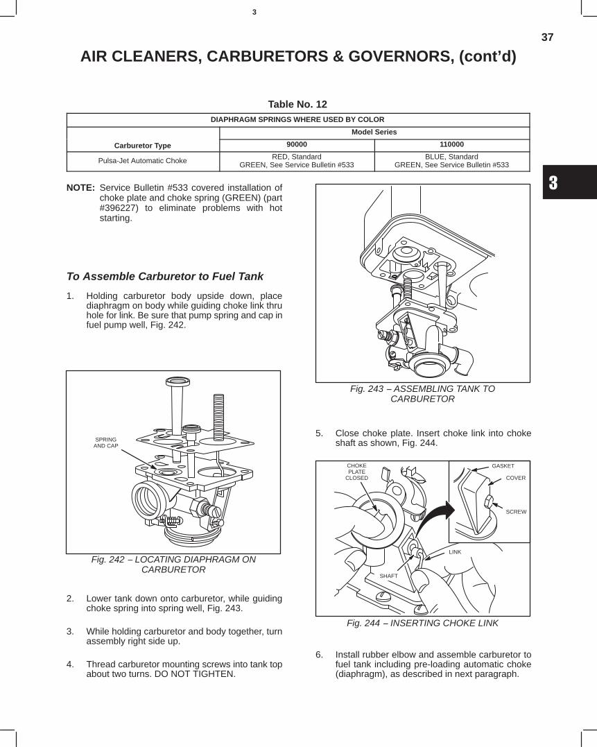
37
3
AIR CLEANERS, CARBURETORS & GOVERNORS, (cont’d)
Table No. 12DIAPHRAGM SPRINGS WHERE USED BY COLOR
Model Series
Carburetor Type 90000 110000
Pulsa-Jet Automatic Choke RED, StandardGREEN, See Service Bulletin #533
BLUE, StandardGREEN, See Service Bulletin #533
NOTE: Service Bulletin #533 covered installation ofchoke plate and choke spring (GREEN) (part#396227) to eliminate problems with hotstarting.
To Assemble Carburetor to Fuel Tank
1. Holding carburetor body upside down, placediaphragm on body while guiding choke link thruhole for link. Be sure that pump spring and cap infuel pump well, Fig. 242.
Fig. 242 − LOCATING DIAPHRAGM ONCARBURETOR
SPRINGAND CAP
2. Lower tank down onto carburetor, while guidingchoke spring into spring well, Fig. 243.
3. While holding carburetor and body together, turnassembly right side up.
4. Thread carburetor mounting screws into tank topabout two turns. DO NOT TIGHTEN.
Fig. 243 − ASSEMBLING TANK TOCARBURETOR
5. Close choke plate. Insert choke link into chokeshaft as shown, Fig. 244.
Fig. 244 − INSERTING CHOKE LINK
GASKET
COVER
SCREW
CHOKEPLATE
CLOSED
SHAFT
LINK
6. Install rubber elbow and assemble carburetor tofuel tank including pre-loading automatic choke(diaphragm), as described in next paragraph.
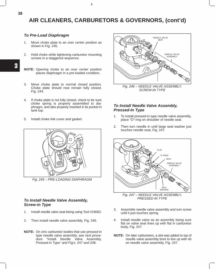
38
3
AIR CLEANERS, CARBURETORS & GOVERNORS, (cont’d)
To Pre-Load Diaphragm
1. Move choke plate to an over center position asshown in Fig. 245.
2. Hold choke while tightening carburetor mountingscrews in a staggered sequence.
NOTE: Opening choke to an over center positionplaces diaphragm in a pre-loaded condition.
3. Move choke plate to normal closed position.Choke plate should now remain fully closed,Fig. 244.
4. If choke plate is not fully closed, check to be surechoke spring is properly assembled to dia-phragm, and also properly inserted in its pocket intank top.
5. Install choke link cover and gasket.
Fig. 245 − PRE-LOADING DIAPHRAGM
To Install Needle Valve Assembly,Screw-in Type
1. Install needle valve seat being using Tool #19062.
2. Then install needle valve assembly, Fig. 246.
NOTE: On zinc carburetor bodies that use pressed-intype needle valve assembly, see next proce-dure “Install Needle Valve Assembly,Pressed-in Type” and Fig’s. 247 and 248.
Fig. 246 − NEEDLE VALVE ASSEMBLY,SCREW-IN TYPE
NEEDLE VALVESEAT
NEEDLE VALVEASSEMBLY
To Install Needle Valve Assembly,Pressed-In Type
1. To install pressed-in type needle valve assembly,place “O”-ring on shoulder of needle seat.
2. Then turn needle in until large seal washer justtouches needle seat, Fig. 247.
Fig. 247 − NEEDLE VALVE ASSEMBLY,PRESSED-IN TYPE
FLAT
“O”-RING
SEALWASHER
NEEDLE VALVEASSEMBLY
SEAT
3. Assemble needle valve assembly and turn screwuntil it just touches spring.
4. Install needle valve as an assembly being sureflat on valve seat lines up with flat in carburetorbody, Fig. 247.
NOTE: On later carburetors, a slot was added to top ofneedle valve assembly bore to line up with ribon needle valve assembly, Fig. 247.
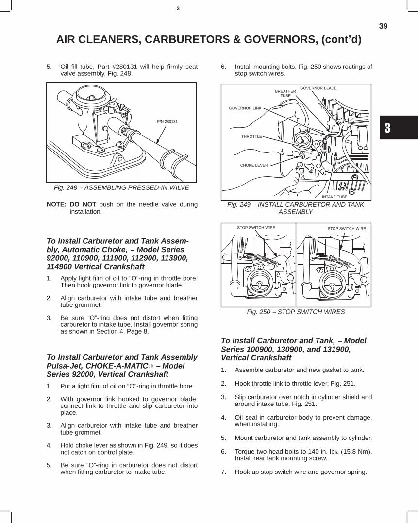
39
3
AIR CLEANERS, CARBURETORS & GOVERNORS, (cont’d)
5. Oil fill tube, Part #280131 will help firmly seatvalve assembly, Fig. 248.
Fig. 248 − ASSEMBLING PRESSED-IN VALVE
P/N 280131
NOTE: DO NOT push on the needle valve duringinstallation.
To Install Carburetor and Tank Assem-bly, Automatic Choke, − Model Series92000, 110900, 111900, 112900, 113900,114900 Vertical Crankshaft1. Apply light film of oil to “O”-ring in throttle bore.
Then hook governor link to governor blade.
2. Align carburetor with intake tube and breathertube grommet.
3. Be sure “O”-ring does not distort when fittingcarburetor to intake tube. Install governor springas shown in Section 4, Page 8.
To Install Carburetor and Tank AssemblyPulsa-Jet, CHOKE-A-MATIC − ModelSeries 92000, Vertical Crankshaft1. Put a light film of oil on “O”-ring in throttle bore.
2. With governor link hooked to governor blade,connect link to throttle and slip carburetor intoplace.
3. Align carburetor with intake tube and breathertube grommet.
4. Hold choke lever as shown in Fig. 249, so it doesnot catch on control plate.
5. Be sure “O”-ring in carburetor does not distortwhen fitting carburetor to intake tube.
6. Install mounting bolts. Fig. 250 shows routings ofstop switch wires.
Fig. 249 − INSTALL CARBURETOR AND TANKASSEMBLY
GOVERNOR BLADE
GOVERNOR LINK
CHOKE LEVER
THROTTLE
BREATHERTUBE
INTAKE TUBE
Fig. 250 − STOP SWITCH WIRES
STOP SWITCH WIRE STOP SWITCH WIRE
To Install Carburetor and Tank, − ModelSeries 100900, 130900, and 131900,Vertical Crankshaft
1. Assemble carburetor and new gasket to tank.
2. Hook throttle link to throttle lever, Fig. 251.
3. Slip carburetor over notch in cylinder shield andaround intake tube, Fig. 251.
4. Oil seal in carburetor body to prevent damage,when installing.
5. Mount carburetor and tank assembly to cylinder.
6. Torque two head bolts to 140 in. lbs. (15.8 Nm).Install rear tank mounting screw.
7. Hook up stop switch wire and governor spring.
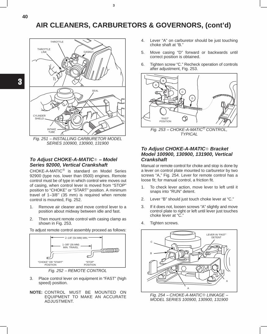
40
3
AIR CLEANERS, CARBURETORS & GOVERNORS, (cont’d)
Fig. 251 − INSTALLING CARBURETOR MODELSERIES 100900, 130900, 131900
THROTTLE
THROTTLELINK
SEAL
CYLINDERSHIELD
INTAKETUBE
GASKET
To Adjust CHOKE-A-MATIC − ModelSeries 92000, Vertical CrankshaftCHOKE-A-MATIC is standard on Model Series92900 (type nos. lower than 0500) engines. Remotecontrol must be of type in which control wire moves outof casing, when control lever is moved from “STOP”position to “CHOKE” or “START” position. A minimumtravel of 1−3/8" (35 mm) is required when remotecontrol is mounted, Fig. 252.
1. Remove air cleaner and move control lever to aposition about midway between idle and fast.
2. Then mount remote control with casing clamp asshown in Fig. 253.
To adjust remote control assembly proceed as follows:
Fig. 252 − REMOTE CONTROL
2−1/8” (54 MM) MIN.
1−3/8” (35 MM)MIN. TRAVEL
“CHOKE” OR “START”POSITION
“STOP”POSITION
3. Place control lever on equipment in “FAST” (highspeed) position.
NOTE: CONTROL MUST BE MOUNTED ONEQUIPMENT TO MAKE AN ACCURATEADJUSTMENT.
4. Lever “A” on carburetor should be just touchingchoke shaft at “B.”
5. Move casing “D” forward or backwards untilcorrect position is obtained.
6. Tighten screw “C.” Recheck operation of controlsafter adjustment, Fig. 253.
Fig. 253 − CHOKE-A-MATIC CONTROL,TYPICAL
“FAST” POSITION
A
B
C
D
To Adjust CHOKE-A-MATIC BracketModel 100900, 130900, 131900, VerticalCrankshaftManual or remote control for choke and stop is done bya lever on control plate mounted to carburetor by twoscrews “A,” Fig. 254. Lever for remote control has aloose fit; for manual control, a friction fit.
1. To check lever action, move lever to left until itsnaps into “RUN” detent.
2. Lever “B” should just touch choke lever at “C.”
3. If it does not, loosen screws “A” slightly and movecontrol plate to right or left until lever just toucheschoke lever at “C.”
4. Tighten screws.
Fig. 254 − CHOKE-A-MATIC LINKAGE −MODEL SERIES 100900, 130900, 131900
LEVER IN “FAST”DETENT
A
B
C
A
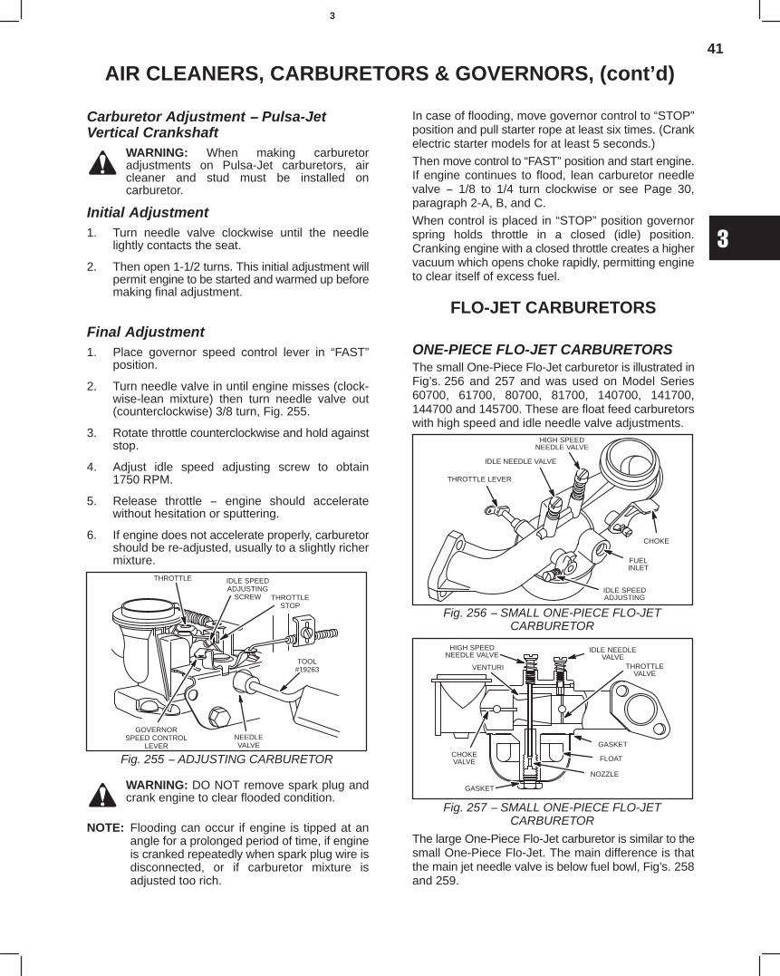
41
3
AIR CLEANERS, CARBURETORS & GOVERNORS, (cont’d)
Carburetor Adjustment − Pulsa-JetVertical Crankshaft
WARNING: When making carburetoradjustments on Pulsa-Jet carburetors, aircleaner and stud must be installed oncarburetor.
Initial Adjustment1. Turn needle valve clockwise until the needle
lightly contacts the seat.
2. Then open 1-1/2 turns. This initial adjustment willpermit engine to be started and warmed up beforemaking final adjustment.
Final Adjustment1. Place governor speed control lever in “FAST”
position.
2. Turn needle valve in until engine misses (clock-wise-lean mixture) then turn needle valve out(counterclockwise) 3/8 turn, Fig. 255.
3. Rotate throttle counterclockwise and hold againststop.
4. Adjust idle speed adjusting screw to obtain1750 RPM.
5. Release throttle − engine should acceleratewithout hesitation or sputtering.
6. If engine does not accelerate properly, carburetorshould be re-adjusted, usually to a slightly richermixture.
Fig. 255 − ADJUSTING CARBURETOR
IDLE SPEEDADJUSTING
SCREW THROTTLESTOP
THROTTLE
GOVERNORSPEED CONTROL
LEVERNEEDLEVALVE
TOOL#19263
WARNING: DO NOT remove spark plug andcrank engine to clear flooded condition.
NOTE: Flooding can occur if engine is tipped at anangle for a prolonged period of time, if engineis cranked repeatedly when spark plug wire isdisconnected, or if carburetor mixture isadjusted too rich.
In case of flooding, move governor control to “STOP”position and pull starter rope at least six times. (Crankelectric starter models for at least 5 seconds.)
Then move control to “FAST” position and start engine.If engine continues to flood, lean carburetor needlevalve − 1/8 to 1/4 turn clockwise or see Page 30,paragraph 2-A, B, and C.
When control is placed in “STOP” position governorspring holds throttle in a closed (idle) position.Cranking engine with a closed throttle creates a highervacuum which opens choke rapidly, permitting engineto clear itself of excess fuel.
FLO-JET CARBURETORS
ONE-PIECE FLO-JET CARBURETORSThe small One-Piece Flo-Jet carburetor is illustrated inFig’s. 256 and 257 and was used on Model Series60700, 61700, 80700, 81700, 140700, 141700,144700 and 145700. These are float feed carburetorswith high speed and idle needle valve adjustments.
Fig. 256 − SMALL ONE-PIECE FLO-JETCARBURETOR
HIGH SPEEDNEEDLE VALVE
IDLE NEEDLE VALVE
THROTTLE LEVER
FUELINLET
IDLE SPEEDADJUSTING
CHOKE
Fig. 257 − SMALL ONE-PIECE FLO-JETCARBURETOR
IDLE NEEDLEVALVE
THROTTLEVALVE
GASKET
FLOAT
NOZZLE
GASKET
CHOKEVALVE
VENTURI
HIGH SPEEDNEEDLE VALVE
The large One-Piece Flo-Jet carburetor is similar to thesmall One-Piece Flo-Jet. The main difference is thatthe main jet needle valve is below fuel bowl, Fig’s. 258and 259.
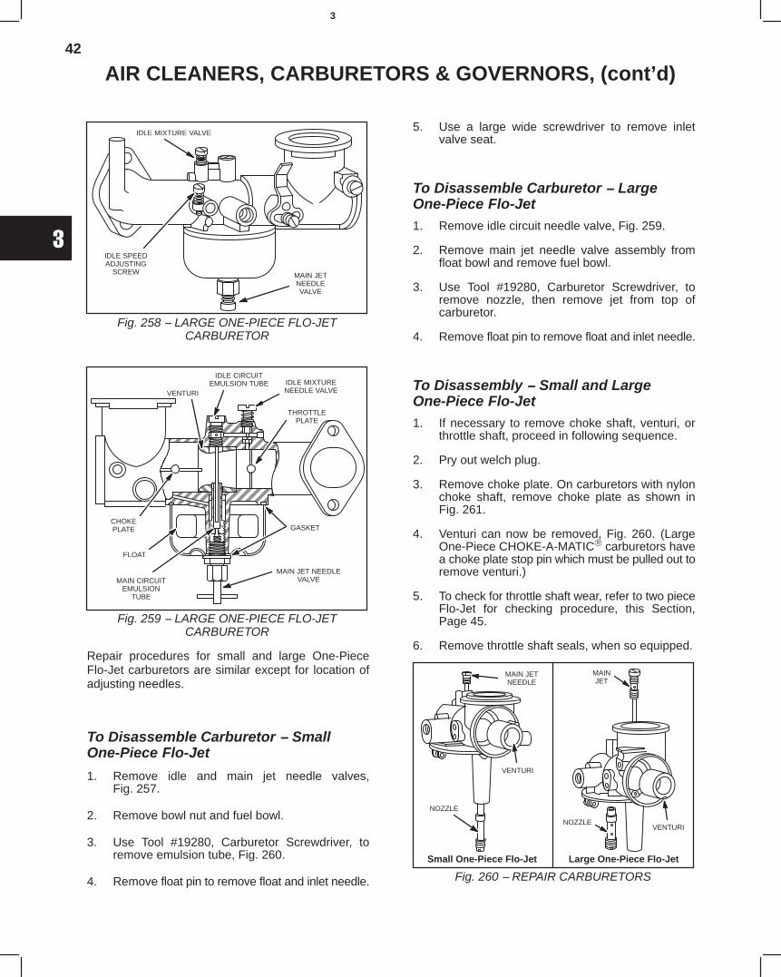
42
3
AIR CLEANERS, CARBURETORS & GOVERNORS, (cont’d)
Fig. 258 − LARGE ONE-PIECE FLO-JETCARBURETOR
MAIN JETNEEDLEVALVE
IDLE SPEEDADJUSTING
SCREW
IDLE MIXTURE VALVE
Fig. 259 − LARGE ONE-PIECE FLO-JETCARBURETOR
IDLE CIRCUITEMULSION TUBE IDLE MIXTURE
NEEDLE VALVE
ÍÍÍÍÍÍÍÍÍÍÍÍÍÍÍÍ
ÍÍÍÍÍÍÍÍÍ
ÍÍÍÍÍÍÈÈÈÈÇÇÇ
ÇÇÇÇÇÇ
ÍÍÍÍÍÍÍÍÍÍÍÍÍÍÍÍ
ÈÈÍÍÍÍÍÍÍÍÍ
È
ÍÍÍÍÍÍ
ÍÍÍÍ
THROTTLEPLATE
VENTURI
CHOKEPLATE
MAIN CIRCUITEMULSION
TUBE
FLOAT
GASKET
MAIN JET NEEDLEVALVE
ÍÍÍÍ
Repair procedures for small and large One-PieceFlo-Jet carburetors are similar except for location ofadjusting needles.
To Disassemble Carburetor − SmallOne-Piece Flo-Jet
1. Remove idle and main jet needle valves,Fig. 257.
2. Remove bowl nut and fuel bowl.
3. Use Tool #19280, Carburetor Screwdriver, toremove emulsion tube, Fig. 260.
4. Remove float pin to remove float and inlet needle.
5. Use a large wide screwdriver to remove inletvalve seat.
To Disassemble Carburetor − LargeOne-Piece Flo-Jet1. Remove idle circuit needle valve, Fig. 259.
2. Remove main jet needle valve assembly fromfloat bowl and remove fuel bowl.
3. Use Tool #19280, Carburetor Screwdriver, toremove nozzle, then remove jet from top ofcarburetor.
4. Remove float pin to remove float and inlet needle.
To Disassembly − Small and LargeOne-Piece Flo-Jet1. If necessary to remove choke shaft, venturi, or
throttle shaft, proceed in following sequence.
2. Pry out welch plug.
3. Remove choke plate. On carburetors with nylonchoke shaft, remove choke plate as shown inFig. 261.
4. Venturi can now be removed, Fig. 260. (LargeOne-Piece CHOKE-A-MATIC carburetors havea choke plate stop pin which must be pulled out toremove venturi.)
5. To check for throttle shaft wear, refer to two pieceFlo-Jet for checking procedure, this Section,Page 45.
6. Remove throttle shaft seals, when so equipped.
Small One-Piece Flo-Jet
Fig. 260 − REPAIR CARBURETORS
Large One-Piece Flo-Jet
MAIN JETNEEDLE
VENTURI
NOZZLE
VENTURINOZZLE
MAINJET
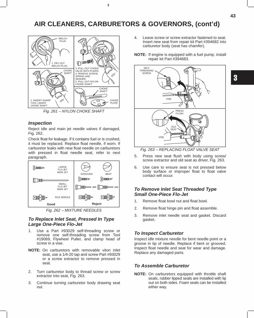
43
3
AIR CLEANERS, CARBURETORS & GOVERNORS, (cont’d)
Fig. 261 − NYLON CHOKE SHAFT
WELCHPLUG
1. PRY OUT WELCH PLUG
2. INSERT SHARPTOOL UNDERCHOKE SHAFT
3. PULL OUT CHOKEVALVE WITH PLIERS.4. REMOVE SCREW,SPRING ANDWASHER.5. PULL OUT NYLONCHOKE SHAFT.
CHOKESHAFT
CHOKESHAFT
CHOKEPLATE
InspectionReject idle and main jet needle valves if damaged,Fig. 262.
Check float for leakage. If it contains fuel or is crushed,it must be replaced. Replace float needle, if worn. Ifcarburetor leaks with new float needle on carburetorswith pressed in float needle seat, refer to nextparagraph.
Fig. 262 − MIXTURE NEEDLES
Good Reject
LARGEFLO-JETMAIN JET
SMALLFLO-JETMAIN JET
IDLE NEEDLE
GROOVED BENT
To Replace Inlet Seat, Pressed In TypeLarge One-Piece Flo-Jet1. Use a Part #93029 self-threading screw or
remove one self-threading screw from Tool#19069, Flywheel Puller, and clamp head ofscrew in a vise.
NOTE: On carburetors with removable viton inletseat, use a 1/4-20 tap and screw Part #93029or a screw extractor to remove pressed inseat.
2. Turn carburetor body to thread screw or screwextractor into seat, Fig. 263.
3. Continue turning carburetor body drawing seatout.
4. Leave screw or screw extractor fastened to seat.Insert new seat from repair kit Part #394682 intocarburetor body (seat has chamfer).
NOTE: If engine is equipped with a fuel pump, installrepair kit Part #394683.
Fig. 263 − REPLACING FLOAT VALVE SEAT
SELFTHREADING
SCREW
VISE
VISE
PRESSFLUSH
OLDSEAT
5. Press new seat flush with body using screw/screw extractor and old seat as driver, Fig. 263.
6. Use care to ensure seat is not pressed belowbody surface or improper float to float valvecontact will occur.
To Remove Inlet Seat Threaded TypeSmall One-Piece Flo-Jet1. Remove float bowl nut and float bowl.
2. Remove float hinge pin and float assemble.
3. Remove inlet needle seat and gasket. Discardgasket.
To Inspect CarburetorInspect idle mixture needle for bent needle point or agroove in tip of needle. Replace if bent or grooved.Inspect float needle and seat for wear and damage.Replace any damaged parts.
To Assemble Carburetor
NOTE: On carburetors equipped with throttle shaftseals, rubber lipped seals are installed with lipout on both sides. Foam seals can be installedeither way.
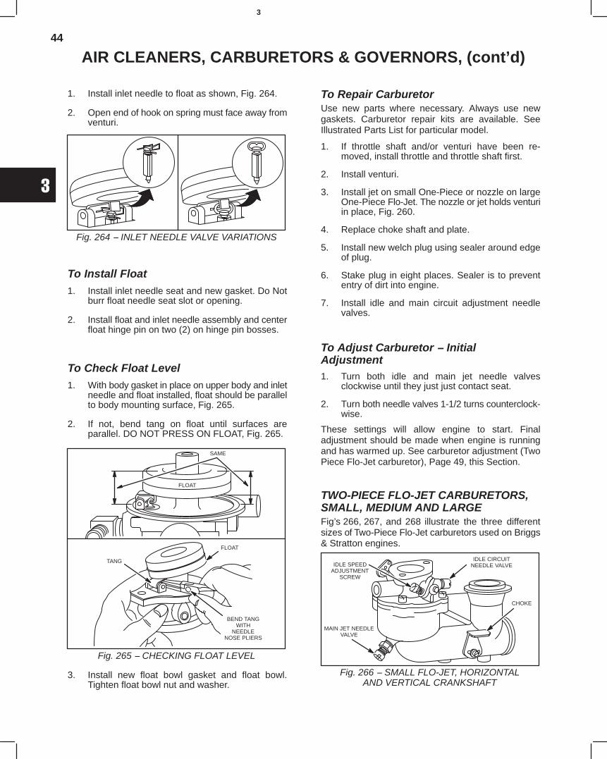
44
3
AIR CLEANERS, CARBURETORS & GOVERNORS, (cont’d)
1. Install inlet needle to float as shown, Fig. 264.
2. Open end of hook on spring must face away fromventuri.
Fig. 264 − INLET NEEDLE VALVE VARIATIONS
To Install Float1. Install inlet needle seat and new gasket. Do Not
burr float needle seat slot or opening.
2. Install float and inlet needle assembly and centerfloat hinge pin on two (2) on hinge pin bosses.
To Check Float Level1. With body gasket in place on upper body and inlet
needle and float installed, float should be parallelto body mounting surface, Fig. 265.
2. If not, bend tang on float until surfaces areparallel. DO NOT PRESS ON FLOAT, Fig. 265.
Fig. 265 − CHECKING FLOAT LEVEL
TANG
FLOAT
SAME
FLOAT
BEND TANGWITH
NEEDLENOSE PLIERS
3. Install new float bowl gasket and float bowl.Tighten float bowl nut and washer.
To Repair CarburetorUse new parts where necessary. Always use newgaskets. Carburetor repair kits are available. SeeIllustrated Parts List for particular model.
1. If throttle shaft and/or venturi have been re-moved, install throttle and throttle shaft first.
2. Install venturi.
3. Install jet on small One-Piece or nozzle on largeOne-Piece Flo-Jet. The nozzle or jet holds venturiin place, Fig. 260.
4. Replace choke shaft and plate.
5. Install new welch plug using sealer around edgeof plug.
6. Stake plug in eight places. Sealer is to prevententry of dirt into engine.
7. Install idle and main circuit adjustment needlevalves.
To Adjust Carburetor − InitialAdjustment1. Turn both idle and main jet needle valves
clockwise until they just just contact seat.
2. Turn both needle valves 1-1/2 turns counterclock-wise.
These settings will allow engine to start. Finaladjustment should be made when engine is runningand has warmed up. See carburetor adjustment (TwoPiece Flo-Jet carburetor), Page 49, this Section.
TWO-PIECE FLO-JET CARBURETORS,SMALL, MEDIUM AND LARGEFig’s 266, 267, and 268 illustrate the three differentsizes of Two-Piece Flo-Jet carburetors used on Briggs& Stratton engines.
Fig. 266 − SMALL FLO-JET, HORIZONTALAND VERTICAL CRANKSHAFT
IDLE CIRCUITNEEDLE VALVE
CHOKE
MAIN JET NEEDLEVALVE
IDLE SPEEDADJUSTMENT
SCREW
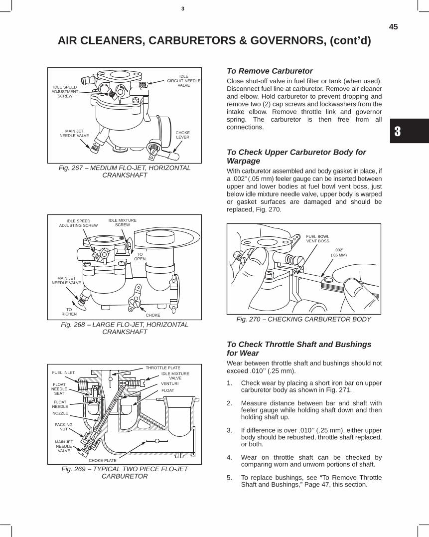
45
3
AIR CLEANERS, CARBURETORS & GOVERNORS, (cont’d)
Fig. 267 − MEDIUM FLO-JET, HORIZONTALCRANKSHAFT
CHOKELEVER
IDLECIRCUIT NEEDLE
VALVE
MAIN JETNEEDLE VALVE
IDLE SPEEDADJUSTMENT
SCREW
Fig. 268 − LARGE FLO-JET, HORIZONTALCRANKSHAFT
IDLE SPEEDADJUSTING SCREW
TOOPEN
IDLE MIXTURESCREW
CHOKE
MAIN JETNEEDLE VALVE
TORICHEN
Fig. 269 − TYPICAL TWO PIECE FLO-JETCARBURETOR
ÈÈÈÈÈÈÈÈÈÈÈÈÈÈÈÈ
ÈÈÈÈÈÈ
ÈÈÈÈÈÈ
ÈÈÈÈÈÈÍÍÍÍÍÍÍÍÍÍÍÍÍÍÍÍÍÍÍÍÍÍÍÍÍÍÍÍÍÍ
ÈÈÍÍÍÍ
ÍÍÍÍÍÍÍÍÍÍÍÍÍÍÍÍÍÍÍÍÍÍÍÍÍÍÍÍÍÍÍÍÍÍÍÍÍÍÍÍÍÍÍÍÍ
ÍÍÍÍÍÍÍÍÍÍÍÍ
ÍÍÍ
ÇÇÇÇÇÇÇÇ
ÍÍÍÍÍÍÍÍÍÍÍÍÍÍÍÍÍÍÍÍ
ÍÍÍÍÍÍÍÍÍÍ
ÍÍÍ
THROTTLE PLATE
IDLE MIXTUREVALVE
VENTURI
FLOAT
FUEL INLET
FLOATNEEDLE
SEAT
FLOATNEEDLE
NOZZLE
PACKINGNUT
MAIN JETNEEDLEVALVE
CHOKE PLATE
ÈÈ
To Remove CarburetorClose shut-off valve in fuel filter or tank (when used).Disconnect fuel line at carburetor. Remove air cleanerand elbow. Hold carburetor to prevent dropping andremove two (2) cap screws and lockwashers from theintake elbow. Remove throttle link and governorspring. The carburetor is then free from allconnections.
To Check Upper Carburetor Body forWarpageWith carburetor assembled and body gasket in place, ifa .002” (.05 mm) feeler gauge can be inserted betweenupper and lower bodies at fuel bowl vent boss, justbelow idle mixture needle valve, upper body is warpedor gasket surfaces are damaged and should bereplaced, Fig. 270.
Fig. 270 − CHECKING CARBURETOR BODY
.002”(.05 MM)
FUEL BOWLVENT BOSS
To Check Throttle Shaft and Bushingsfor WearWear between throttle shaft and bushings should notexceed .010" (.25 mm).
1. Check wear by placing a short iron bar on uppercarburetor body as shown in Fig. 271.
2. Measure distance between bar and shaft withfeeler gauge while holding shaft down and thenholding shaft up.
3. If difference is over .010" (.25 mm), either upperbody should be rebushed, throttle shaft replaced,or both.
4. Wear on throttle shaft can be checked bycomparing worn and unworn portions of shaft.
5. To replace bushings, see “To Remove ThrottleShaft and Bushings,” Page 47, this section.
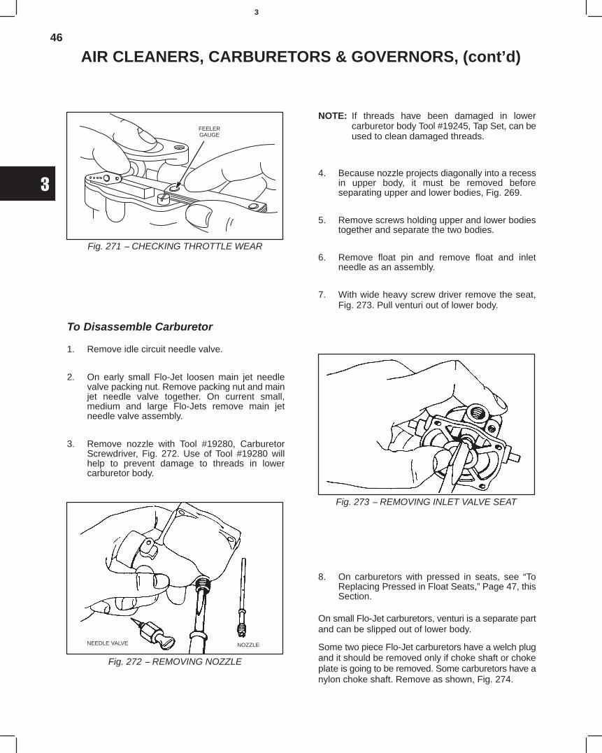
46
3
AIR CLEANERS, CARBURETORS & GOVERNORS, (cont’d)
Fig. 271 − CHECKING THROTTLE WEAR
FEELERGAUGE
To Disassemble Carburetor
1. Remove idle circuit needle valve.
2. On early small Flo-Jet loosen main jet needlevalve packing nut. Remove packing nut and mainjet needle valve together. On current small,medium and large Flo-Jets remove main jetneedle valve assembly.
3. Remove nozzle with Tool #19280, CarburetorScrewdriver, Fig. 272. Use of Tool #19280 willhelp to prevent damage to threads in lowercarburetor body.
Fig. 272 − REMOVING NOZZLE
NEEDLE VALVE NOZZLE
NOTE: If threads have been damaged in lowercarburetor body Tool #19245, Tap Set, can beused to clean damaged threads.
4. Because nozzle projects diagonally into a recessin upper body, it must be removed beforeseparating upper and lower bodies, Fig. 269.
5. Remove screws holding upper and lower bodiestogether and separate the two bodies.
6. Remove float pin and remove float and inletneedle as an assembly.
7. With wide heavy screw driver remove the seat,Fig. 273. Pull venturi out of lower body.
Fig. 273 − REMOVING INLET VALVE SEAT
8. On carburetors with pressed in seats, see “ToReplacing Pressed in Float Seats,” Page 47, thisSection.
On small Flo-Jet carburetors, venturi is a separate partand can be slipped out of lower body.
Some two piece Flo-Jet carburetors have a welch plugand it should be removed only if choke shaft or chokeplate is going to be removed. Some carburetors have anylon choke shaft. Remove as shown, Fig. 274.
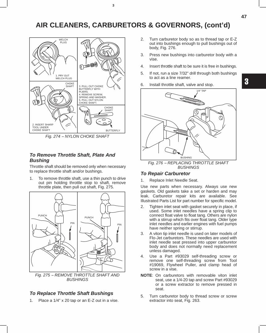
47
3
AIR CLEANERS, CARBURETORS & GOVERNORS, (cont’d)
Fig. 274 − NYLON CHOKE SHAFT
WELCHPLUG
1. PRY OUT WELCH PLUG
2. INSERT SHARPTOOL UNDERCHOKE SHAFT
3. PULL OUT CHOKEBUTTERFLY WITH PLIERS.4. REMOVE SCREW,SPRING AND WASHER.5. PULL OUT NYLONCHOKE SHAFT.
CHOKESHAFT
CHOKESHAFT
BUTTERFLY
To Remove Throttle Shaft, Plate AndBushingThrottle shaft should be removed only when necessaryto replace throttle shaft and/or bushings.
1. To remove throttle shaft, use a thin punch to driveout pin holding throttle stop to shaft, removethrottle plate, then pull out shaft, Fig. 275.
Fig. 275 − REMOVE THROTTLE SHAFT ANDBUSHINGS
PUNCH
PINPIN
PUNCH
To Replace Throttle Shaft Bushings1. Place a 1/4” x 20 tap or an E-Z out in a vise.
2. Turn carburetor body so as to thread tap or E-Zout into bushings enough to pull bushings out ofbody, Fig. 276.
3. Press new bushings into carburetor body with avise.
4. Insert throttle shaft to be sure it is free in bushings.
5. If not, run a size 7/32” drill through both bushingsto act as a line reamer.
6. Install throttle shaft, valve and stop.
Fig. 276 − REPLACING THROTTLE SHAFTBUSHINGS
1/4” TAP
BUSHING
To Repair Carburetor1. Replace Inlet Needle Seat.
Use new parts when necessary. Always use newgaskets. Old gaskets take a set or harden and mayleak. Carburetor repair kits are available. SeeIllustrated Parts List for part number for specific model.2. Tighten inlet seat with gasket securely in place, if
used. Some inlet needles have a spring clip toconnect float valve to float tang. Others are nylonwith a stirrup which fits over float tang. Older typeinlet needles and earlier engines with fuel pumpshave neither spring or stirrup.
3. A viton tip inlet needle is used on later models ofFlo-Jet carburetors. These needles are used withinlet needle seat pressed into upper carburetorbody and does not normally need replacementunless damaged.
4. Use a Part #93029 self-threading screw orremove one self-threading screw from Tool#19069, Flywheel Puller, and clamp head ofscrew in a vise.
NOTE: On carburetors with removable viton inletseat, use a 1/4-20 tap and screw Part #93029or a screw extractor to remove pressed inseat.
5. Turn carburetor body to thread screw or screwextractor into seat, Fig. 263.
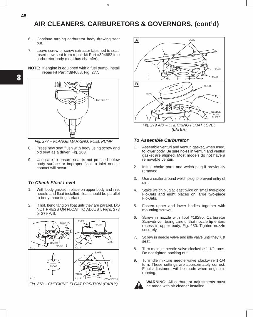
48
3
AIR CLEANERS, CARBURETORS & GOVERNORS, (cont’d)
6. Continue turning carburetor body drawing seatout.
7. Leave screw or screw extractor fastened to seat.Insert new seat from repair kit Part #394682 intocarburetor body (seat has chamfer).
NOTE: If engine is equipped with a fuel pump, installrepair kit Part #394683, Fig. 277.
Fig. 277 − FLANGE MARKING, FUEL PUMP
LETTER “P”
8. Press new seat flush with body using screw andold seat as a driver, Fig. 263.
9. Use care to ensure seat is not pressed belowbody surface or improper float to inlet needlecontact will occur.
To Check Float Level1. With body gasket in place on upper body and inlet
needle and float installed, float should be parallelto body mounting surface.
2. If not, bend tang on float until they are parallel. DONOT PRESS ON FLOAT TO ADJUST, Fig’s. 278or 279 A/B.
Fig. 278 − CHECKING FLOAT POSITION (EARLY)
ILL. 1 ILL. 2
ILL. 3 ILL. 4
13/32” TO7/16”
LEVERFLOAT
LEVER
SAME
FLOAT
FLOAT
1/2” APPROX.
SAME
TANG
A
B
Fig. 279 A/B − CHECKING FLOAT LEVEL(LATER)
SAME
TANG
FLOAT
TANG
FLOAT
NEEDLENOSE
PLIERS
To Assemble Carburetor1. Assemble venturi and venturi gasket, when used,
to lower body. Be sure holes in venturi and venturigasket are aligned. Most models do not have aremovable venturi.
2. Install choke parts and welch plug if previouslyremoved.
3. Use a sealer around welch plug to prevent entry ofdirt.
4. Stake welch plug at least twice on small two-pieceFlo-Jets and eight places on large two-pieceFlo-Jets.
5. Fasten upper and lower bodies together withmounting screws.
6. Screw in nozzle with Tool #19280, CarburetorScrewdriver, being careful that nozzle tip entersrecess in upper body, Fig. 280. Tighten nozzlesecurely.
7. Screw in needle valve and idle valve until they justseat.
8. Turn main jet needle valve clockwise 1-1/2 turns.Do not tighten packing nut.
9. Turn idle mixture needle valve clockwise 1-1/4turn. These settings are approximately correct.Final adjustment will be made when engine isrunning.
WARNING: All carburetor adjustments mustbe made with air cleaner installed.
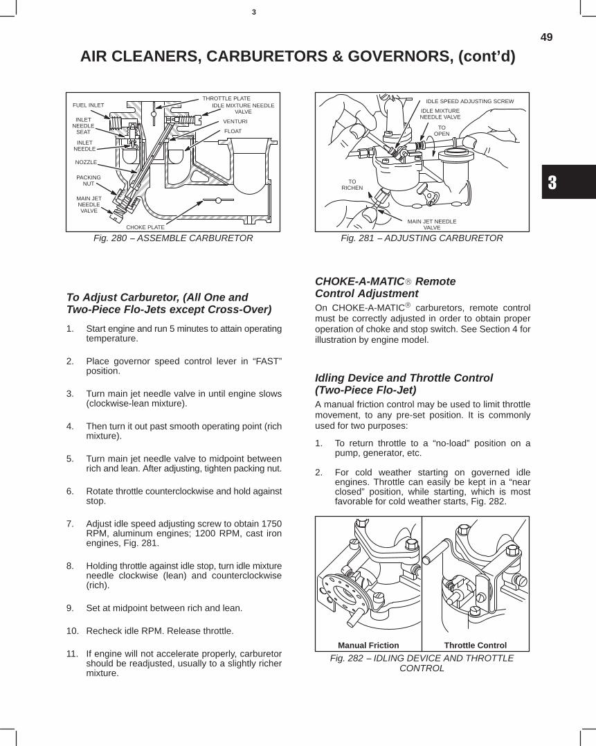
49
3
AIR CLEANERS, CARBURETORS & GOVERNORS, (cont’d)
Fig. 280 − ASSEMBLE CARBURETOR
ÈÈÈÈÈÈÈÈÈÈÈÈ
ÈÈÈÈÈÈ
ÈÈÈÈÈÈÈÈÈÍÍÍÍÍÍÍÍÍÍÍÍÍÍÍÍÍÍÍÍÍÍÍÍÍÍÍÍÍÍ
ÈÈÍÍÍÍ
ÍÍÍÍÍÍÍÍÍÍÍÍÍÍÍÍÍÍÍÍÍÍÍÍÍÍÍÍÍÍÍÍÍÍÍÍÍÍÍÍÍÍÍÍÍ
ÍÍÍÍÍÍÍÍÍÍÍÍ
ÍÍ
ÇÇÇÇÇÇÇÇ
ÍÍÍÍÍÍÍÍÍÍÍÍÍÍÍÍÍÍÍÍ
ÍÍÍÍÍÍÍÍÍÍ
ÍÍÍ
THROTTLE PLATEIDLE MIXTURE NEEDLE
VALVE
VENTURI
FLOAT
FUEL INLET
INLETNEEDLE
SEAT
INLETNEEDLE
NOZZLE
PACKINGNUT
MAIN JETNEEDLEVALVE
CHOKE PLATE
ÈÈ
To Adjust Carburetor, (All One andTwo-Piece Flo-Jets except Cross-Over)
1. Start engine and run 5 minutes to attain operatingtemperature.
2. Place governor speed control lever in “FAST”position.
3. Turn main jet needle valve in until engine slows(clockwise-lean mixture).
4. Then turn it out past smooth operating point (richmixture).
5. Turn main jet needle valve to midpoint betweenrich and lean. After adjusting, tighten packing nut.
6. Rotate throttle counterclockwise and hold againststop.
7. Adjust idle speed adjusting screw to obtain 1750RPM, aluminum engines; 1200 RPM, cast ironengines, Fig. 281.
8. Holding throttle against idle stop, turn idle mixtureneedle clockwise (lean) and counterclockwise(rich).
9. Set at midpoint between rich and lean.
10. Recheck idle RPM. Release throttle.
11. If engine will not accelerate properly, carburetorshould be readjusted, usually to a slightly richermixture.
Fig. 281 − ADJUSTING CARBURETOR
IDLE SPEED ADJUSTING SCREW
IDLE MIXTURENEEDLE VALVE
TOOPEN
TORICHEN
MAIN JET NEEDLEVALVE
CHOKE-A-MATIC RemoteControl AdjustmentOn CHOKE-A-MATIC carburetors, remote controlmust be correctly adjusted in order to obtain properoperation of choke and stop switch. See Section 4 forillustration by engine model.
Idling Device and Throttle Control(Two-Piece Flo-Jet)A manual friction control may be used to limit throttlemovement, to any pre-set position. It is commonlyused for two purposes:
1. To return throttle to a “no-load” position on apump, generator, etc.
2. For cold weather starting on governed idleengines. Throttle can easily be kept in a “nearclosed” position, while starting, which is mostfavorable for cold weather starts, Fig. 282.
Fig. 282 − IDLING DEVICE AND THROTTLECONTROL
Manual Friction Throttle Control
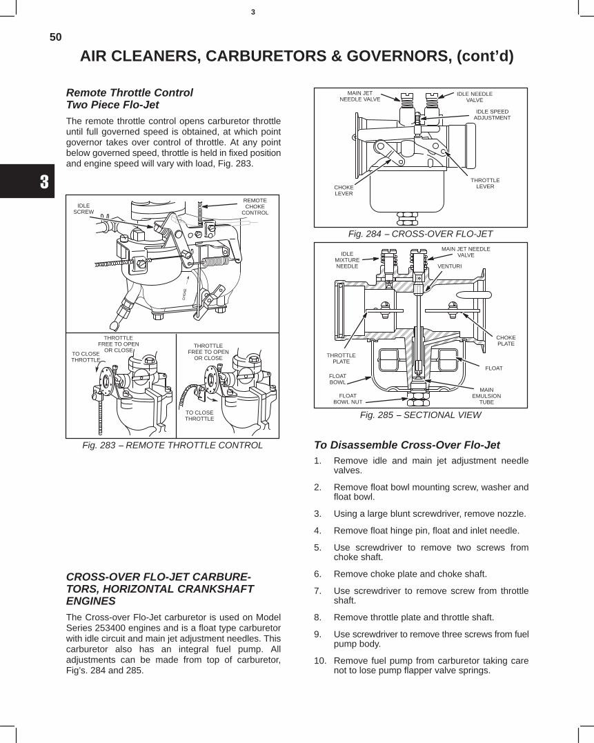
50
3
AIR CLEANERS, CARBURETORS & GOVERNORS, (cont’d)
Remote Throttle ControlTwo Piece Flo-JetThe remote throttle control opens carburetor throttleuntil full governed speed is obtained, at which pointgovernor takes over control of throttle. At any pointbelow governed speed, throttle is held in fixed positionand engine speed will vary with load, Fig. 283.
Fig. 283 − REMOTE THROTTLE CONTROL
THROTTLEFREE TO OPEN
OR CLOSETO CLOSETHROTTLE
THROTTLEFREE TO OPEN
OR CLOSE
TO CLOSETHROTTLE
IDLESCREW
REMOTECHOKE
CONTROL
CROSS-OVER FLO-JET CARBURE-TORS, HORIZONTAL CRANKSHAFTENGINESThe Cross-over Flo-Jet carburetor is used on ModelSeries 253400 engines and is a float type carburetorwith idle circuit and main jet adjustment needles. Thiscarburetor also has an integral fuel pump. Alladjustments can be made from top of carburetor,Fig’s. 284 and 285.
Fig. 284 − CROSS-OVER FLO-JET
IDLE SPEEDADJUSTMENT
MAIN JETNEEDLE VALVE
IDLE NEEDLEVALVE
THROTTLELEVERCHOKE
LEVER
Fig. 285 − SECTIONAL VIEW
MAIN JET NEEDLEVALVE
ÍÍÍÍÍÍÍÍÍÍÍÍÍÍÍÍ
ÍÍÍÍÍÍÍÍÍÍÍÍÍÍÍÍÍÍ
ÍÍÍÍÍÍÍÍÍÍÍÍÍÍÍÍÍÍÍÍÍÍÍÍÍÍÍÍÍÍÍÍÍÍÍ
ÍÍÍÍÍÍÍÍÍÍÍÍÍÍÍÍÍÍÍÍÍÍÍÍÍ
ÍÍÍÍÍÍ
VENTURI
CHOKEPLATE
FLOAT
MAINEMULSION
TUBE
FLOATBOWL
FLOATBOWL NUT
THROTTLEPLATE
IDLEMIXTURENEEDLE
ÍÍÍÍÍÍÍÍÍÍ
To Disassemble Cross-Over Flo-Jet1. Remove idle and main jet adjustment needle
valves.
2. Remove float bowl mounting screw, washer andfloat bowl.
3. Using a large blunt screwdriver, remove nozzle.
4. Remove float hinge pin, float and inlet needle.
5. Use screwdriver to remove two screws fromchoke shaft.
6. Remove choke plate and choke shaft.
7. Use screwdriver to remove screw from throttleshaft.
8. Remove throttle plate and throttle shaft.
9. Use screwdriver to remove three screws from fuelpump body.
10. Remove fuel pump from carburetor taking carenot to lose pump flapper valve springs.
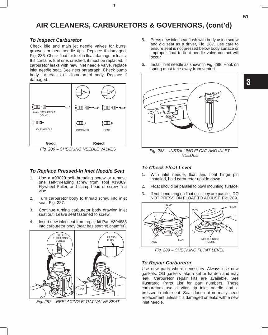
51
3
AIR CLEANERS, CARBURETORS & GOVERNORS, (cont’d)
To Inspect CarburetorCheck idle and main jet needle valves for burrs,grooves or bent needle tips. Replace if damaged,Fig. 286. Check float for fuel in float, damage or leaks.If it contains fuel or is crushed, it must be replaced. Ifcarburetor leaks with new inlet needle valve, replaceinlet needle seat. See next paragraph. Check pumpbody for cracks or distortion of body. Replace ifdamaged.
Fig. 286 − CHECKING NEEDLE VALVESGood Reject
MAIN JET NEEDLEVALVE
IDLE NEEDLE GROOVED BENT
To Replace Pressed-In Inlet Needle Seat1. Use a #93029 self-threading screw or remove
one self-threading screw from Tool #19069,Flywheel Puller, and clamp head of screw in avise.
2. Turn carburetor body to thread screw into inletseat, Fig. 287.
3. Continue turning carburetor body drawing inletseat out. Leave seat fastened to screw.
4. Insert new inlet seat from repair kit Part #394683into carburetor body (seat has starting chamfer).
Fig. 287 − REPLACING FLOAT VALVE SEAT
SELFTHREADING
SCREW
VISE
PRESSFLUSH
5. Press new inlet seat flush with body using screwand old seat as a driver, Fig. 287. Use care toensure seat is not pressed below body surface orimproper float to float needle valve contact willoccur.
6. Install inlet needle as shown in Fig. 288. Hook onspring must face away from venturi.
Fig. 288 − INSTALLING FLOAT AND INLETNEEDLE
To Check Float Level1. With inlet needle, float and float hinge pin
installed, hold carburetor upside down.
2. Float should be parallel to bowl mounting surface.
3. If not, bend tang on float until they are parallel. DONOT PRESS ON FLOAT TO ADJUST, Fig. 289.
Fig. 289 − CHECKING FLOAT LEVEL
SAME
TANGFLOAT NEEDLE NOSE
PLIERS
FLOATTANG
To Repair CarburetorUse new parts where necessary. Always use newgaskets. Old gaskets take a set or harden and mayleak. Carburetor repair kits are available. SeeIllustrated Parts List for part numbers. Thesecarburetors use a viton tip inlet needle and apressed-in inlet seat. Seat does not normally needreplacement unless it is damaged or leaks with a newinlet needle.
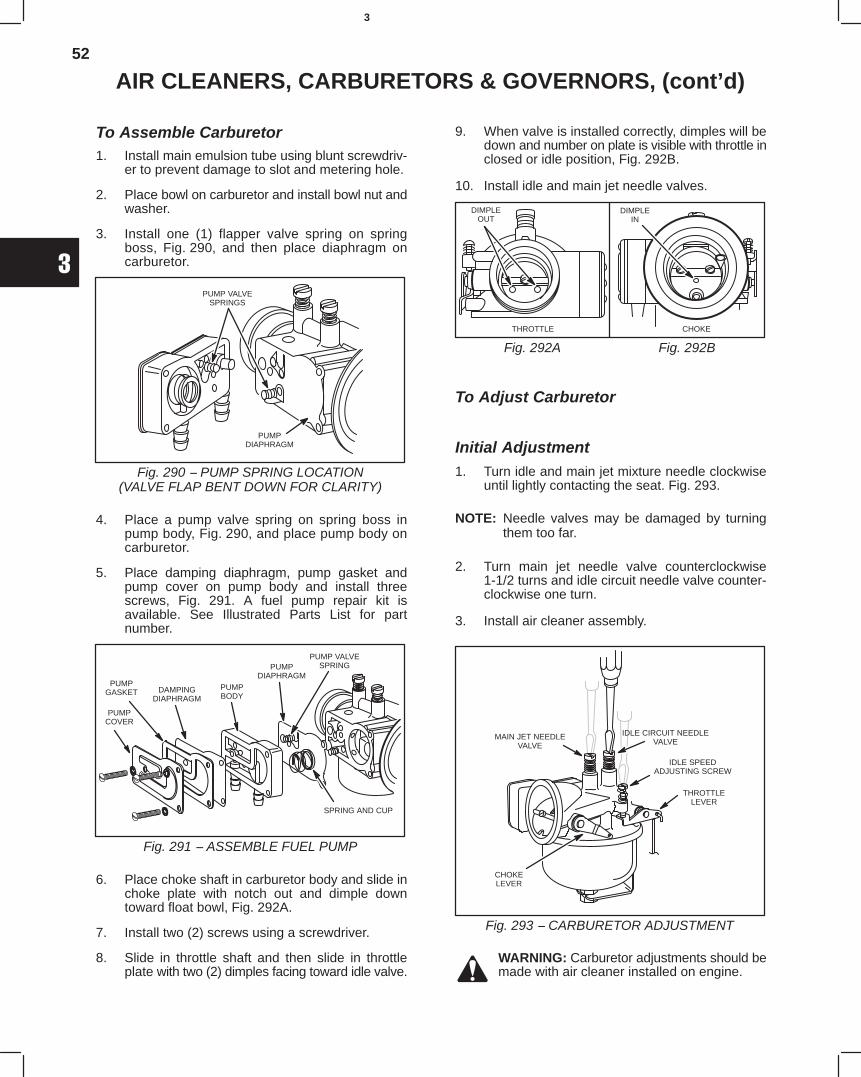
52
3
AIR CLEANERS, CARBURETORS & GOVERNORS, (cont’d)
To Assemble Carburetor1. Install main emulsion tube using blunt screwdriv-
er to prevent damage to slot and metering hole.
2. Place bowl on carburetor and install bowl nut andwasher.
3. Install one (1) flapper valve spring on springboss, Fig. 290, and then place diaphragm oncarburetor.
Fig. 290 − PUMP SPRING LOCATION(VALVE FLAP BENT DOWN FOR CLARITY)
PUMPDIAPHRAGM
PUMP VALVESPRINGS
4. Place a pump valve spring on spring boss inpump body, Fig. 290, and place pump body oncarburetor.
5. Place damping diaphragm, pump gasket andpump cover on pump body and install threescrews, Fig. 291. A fuel pump repair kit isavailable. See Illustrated Parts List for partnumber.
Fig. 291 − ASSEMBLE FUEL PUMP
PUMPCOVER
PUMPGASKET DAMPING
DIAPHRAGMPUMPBODY
PUMPDIAPHRAGM
PUMP VALVESPRING
SPRING AND CUP
6. Place choke shaft in carburetor body and slide inchoke plate with notch out and dimple downtoward float bowl, Fig. 292A.
7. Install two (2) screws using a screwdriver.
8. Slide in throttle shaft and then slide in throttleplate with two (2) dimples facing toward idle valve.
9. When valve is installed correctly, dimples will bedown and number on plate is visible with throttle inclosed or idle position, Fig. 292B.
10. Install idle and main jet needle valves.
Fig. 292BFig. 292A
THROTTLE CHOKE
DIMPLEIN
DIMPLEOUT
To Adjust Carburetor
Initial Adjustment1. Turn idle and main jet mixture needle clockwise
until lightly contacting the seat. Fig. 293.
NOTE: Needle valves may be damaged by turningthem too far.
2. Turn main jet needle valve counterclockwise1-1/2 turns and idle circuit needle valve counter-clockwise one turn.
3. Install air cleaner assembly.
Fig. 293 − CARBURETOR ADJUSTMENT
MAIN JET NEEDLEVALVE
IDLE CIRCUIT NEEDLEVALVE
IDLE SPEEDADJUSTING SCREW
THROTTLELEVER
CHOKELEVER
WARNING: Carburetor adjustments should bemade with air cleaner installed on engine.
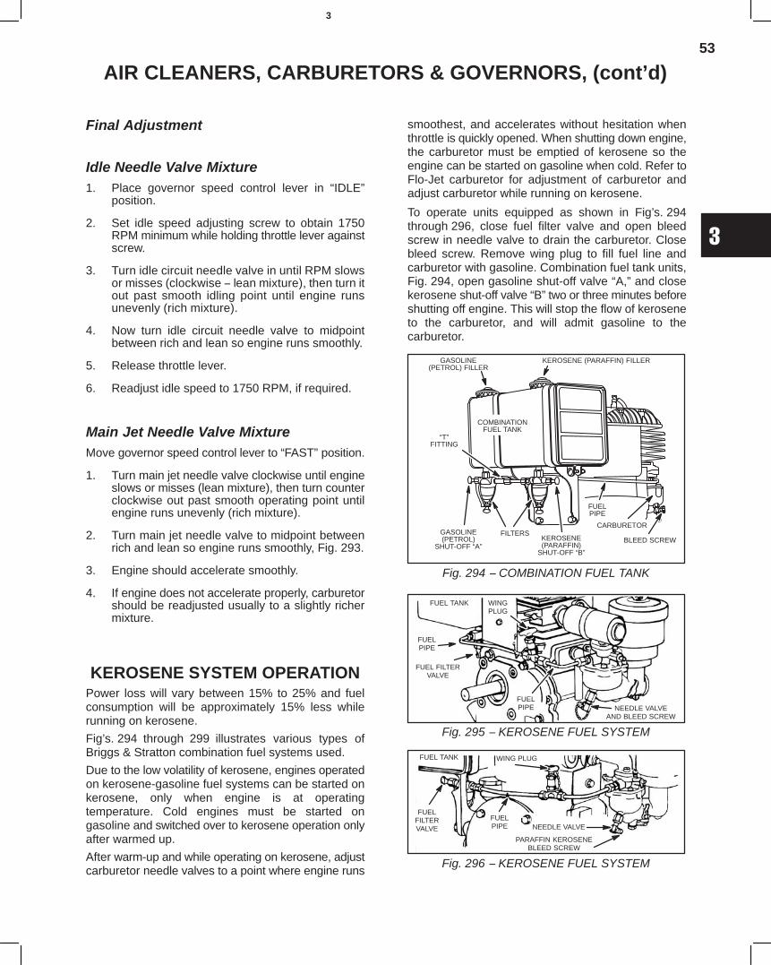
53
3
AIR CLEANERS, CARBURETORS & GOVERNORS, (cont’d)
Final Adjustment
Idle Needle Valve Mixture1. Place governor speed control lever in “IDLE”
position.
2. Set idle speed adjusting screw to obtain 1750RPM minimum while holding throttle lever againstscrew.
3. Turn idle circuit needle valve in until RPM slowsor misses (clockwise − lean mixture), then turn itout past smooth idling point until engine runsunevenly (rich mixture).
4. Now turn idle circuit needle valve to midpointbetween rich and lean so engine runs smoothly.
5. Release throttle lever.
6. Readjust idle speed to 1750 RPM, if required.
Main Jet Needle Valve MixtureMove governor speed control lever to “FAST” position.
1. Turn main jet needle valve clockwise until engineslows or misses (lean mixture), then turn counterclockwise out past smooth operating point untilengine runs unevenly (rich mixture).
2. Turn main jet needle valve to midpoint betweenrich and lean so engine runs smoothly, Fig. 293.
3. Engine should accelerate smoothly.
4. If engine does not accelerate properly, carburetorshould be readjusted usually to a slightly richermixture.
KEROSENE SYSTEM OPERATIONPower loss will vary between 15% to 25% and fuelconsumption will be approximately 15% less whilerunning on kerosene.
Fig’s. 294 through 299 illustrates various types ofBriggs & Stratton combination fuel systems used.
Due to the low volatility of kerosene, engines operatedon kerosene-gasoline fuel systems can be started onkerosene, only when engine is at operatingtemperature. Cold engines must be started ongasoline and switched over to kerosene operation onlyafter warmed up.
After warm-up and while operating on kerosene, adjustcarburetor needle valves to a point where engine runs
smoothest, and accelerates without hesitation whenthrottle is quickly opened. When shutting down engine,the carburetor must be emptied of kerosene so theengine can be started on gasoline when cold. Refer toFlo-Jet carburetor for adjustment of carburetor andadjust carburetor while running on kerosene.
To operate units equipped as shown in Fig’s. 294through 296, close fuel filter valve and open bleedscrew in needle valve to drain the carburetor. Closebleed screw. Remove wing plug to fill fuel line andcarburetor with gasoline. Combination fuel tank units,Fig. 294, open gasoline shut-off valve “A,” and closekerosene shut-off valve “B” two or three minutes beforeshutting off engine. This will stop the flow of keroseneto the carburetor, and will admit gasoline to thecarburetor.
Fig. 294 − COMBINATION FUEL TANK
GASOLINE(PETROL) FILLER
KEROSENE (PARAFFIN) FILLER
COMBINATIONFUEL TANK
GASOLINE(PETROL)
SHUT-OFF “A”
“T”FITTING
FILTERS
FUELPIPE
CARBURETOR
BLEED SCREWKEROSENE(PARAFFIN)
SHUT-OFF “B”
Fig. 295 − KEROSENE FUEL SYSTEM
FUEL TANK WINGPLUG
FUELPIPE
FUEL FILTERVALVE
FUELPIPE NEEDLE VALVE
AND BLEED SCREW
Fig. 296 − KEROSENE FUEL SYSTEM
FUEL TANK WING PLUG
FUELFILTERVALVE
FUELPIPE NEEDLE VALVE
PARAFFIN KEROSENEBLEED SCREW
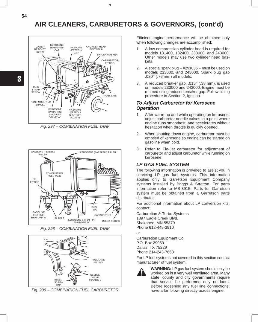
54
3
AIR CLEANERS, CARBURETORS & GOVERNORS, (cont’d)
Fig. 297 − COMBINATION FUEL TANK
KEROSENE(PARAFFIN)
CAPGASOLINE(PETROL)
CAP
LOWERBRACKETSCREW
TANKSTRAPSCREW
TANK MOUNTINGBRACKET
KEROSENE(PARAFFIN)SHUT-OFFVALVE “A”
FUEL LINE
CARBURETORFITTING
CYLINDER HEADBOLT NO. 8
SPACER WASHER
GASOLINE(PETROL)SHUT-OFFVALVE “B”
Fig. 298 − COMBINATION FUEL TANK
GASOLINE (PETROL)FILLER
KEROSENE (PARAFFIN) FILLER
COMBINATIONFUEL TANK
GASOLINE(PETROL)
SHUT-OFF “A”
“T”FITTING
FILTERS
FUELPIPE
CARBURETOR
BLEED SCREWKEROSENE (PARAFFIN)SHUT-OFF “B”
Fig. 299 − COMBINATION FUEL CARBURETOR
NEEDLEVALVE
ASSEMBLY
FUEL LANEFITTING
BLEED SCREW
CAP
Efficient engine performance will be obtained onlywhen following changes are accomplished:
1. A low compression cylinder head is required formodels 131400, 132400, 233000, and 243000.Other models may use two cylinder head gas-kets.
2. A special spark plug − #291835 − must be used onmodels 233000, and 243000. Spark plug gap.030" (.76 mm) all models.
3. A reduced breaker gap, .015" (.38 mm), is usedon models 233000 and 243000. Engine must beretimed using reduced breaker gap. Follow timingprocedure in Section 2, Ignition.
To Adjust Carburetor for KeroseneOperation1. After warm-up and while operating on kerosene,
adjust carburetor needle valves to a point whereengine runs smoothest, and accelerates withouthesitation when throttle is quickly opened.
2. When shutting down engine, carburetor must beemptied of kerosene so engine can be started ongasoline when cold.
3. Refer to Flo-Jet carburetor for adjustment ofcarburetor and adjust carburetor while running onkerosene.
LP GAS FUEL SYSTEMThe following information is provided to assist you inservicing LP gas fuel systems. This informationapplies only to Garretson Equipment Companysystems installed by Briggs & Stratton. For partsinformation refer to MS-3915. Parts for Garretsonsystem must be obtained from a Garretson partsdistributor.For additional information about LP conversion kits,contact:Carburetion & Turbo Systems1897 Eagle Creek Blvd.Shakopee, MN 55379Phone 612-445-3910orCarburetion Equipment Co.P.O. Box 29959Dallas, TX 75229Phone 214-243-7668For LP fuel systems not covered in this section contactmanufacturer of fuel system.
WARNING: LP gas fuel system should only beworked on in a very well ventilated area. Manystate, county and city governments requirethat service be performed only outdoors.Before loosening any fuel line connections,have a fan blowing directly across engine.

55
3
AIR CLEANERS, CARBURETORS & GOVERNORS, (cont’d)
To Check and Adjust Fuel System1. Loosen fuel line at primary regulator.
2. Open valve on cylinder for an instant, to be surethere is pressure in fuel cylinder.
3. Escaping gas can be heard.
4. Shut off valve at cylinder, Fig. 300.
5. Remove fuel line between primary and secondaryregulator (fuel controller).
6. Attach pressure gauge to outlet of primaryregulator, leaving gauge connection looseenough to permit a slight leakage of gas. (This willpermit adjustment of regulator under conditionsof actual gas flow.)
7. Remove cap or top of primary regulator, Fig. 300.
8. Open fuel cylinder valve.
9. Turn pressure regulating screw in primary regula-tor, until a pressure of 1−1/2 P.S.I. (.1 bar) isobtained at pressure gauge.
10. Shut off fuel cylinder valve.
11. Reassemble cap.
12. Remove pressure gauge.
13. Loosen secondary regulator bracket from carbure-tor.
14. Pull secondary regulator away from carburetor sothat short rubber fuel line is disconnected.
15. Assemble fuel line between primary regulator andsecondary regulator (fuel controller).
16. Secondary regulator must remain mounted sodiaphragm is in a vertical plane, Fig. 300.
17. Open fuel cylinder valve.
18. Apply soap suds to outlet at center of secondaryregulator to which rubber fuel line has beenattached.
19. If a bubble forms, it indicates that valve is leakingor not locking off.
20. If no bubble appears, press primer button.
21. A bubble should appear, indicating fuel is flowinginto regulator.
22. Put soap suds on outlet again, then slowly turnadjusting screw at bottom of secondary regulatorcounterclockwise until a bubble forms at outlet.
23. Turn adjusting screw in (clockwise) slowly untilsoap bubbles on outlet no longer form.
24. Hold adjusting screw at this point and tightenlocknut.
25. Press primer button to allow fuel to flow.
26. Release and again put soap suds on outlet tomake certain fuel shuts off.
27. Repeat several times.
28. If bubble should form after primer button isreleased, adjusting screw should be turned inuntil flow stops and soap bubble does not break orenlarge.
29. Loosen fuel line between regulators.
30. Re-assemble secondary regulator to carburetorwith short rubber fuel line in place.
31. Retighten fuel line connections, Fig. 300.
To Adjust Carburetor, LP Fuel System1. Loosen locknut on load needle screw and turn
needle screw in until it seats.
2. Do not force; open 2-1/2 turns.
3. Turn idle circuit needle in until it seats, then openone turn.
4. If engine will not be required to idle, leave idlecircuit needle closed.
5. Depress primer button momentarily, then startengine, run engine to allow it to warm up beforefinal adjustment.
6. With engine running at normal operating speed,turn load needle screw in slowly (clockwise) untilengine starts to miss (lean mixture).
WARNING: Air cleaner element must be inplace when running engine.
7. Then turn load screw out slowly past point of bestoperation until engine begins to run unevenly(rich mixture).
8. Then turn load screw in just enough so engine willrun smoothly.
9. Hold load screw and tighten locknut.
10. Hold throttle at idle position, then release throttle.
11. Engine should accelerate quickly and smoothly.
12. If engine will be required to run at idle, turn idlespeed adjusting screw on throttle until engineruns at proper idle speed for engine model. SeeRepair Check Chart.
13. Hold throttle at this point and turn idle circuitneedle slowly in or out until engine runs atmaximum idle speed.
14. Then readjust idle speed screw until proper idlespeed is obtained.
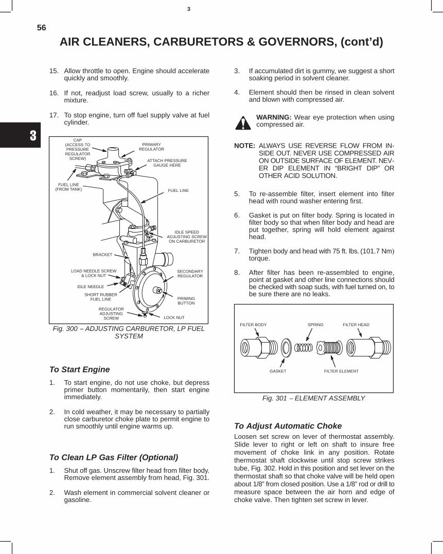
56
3
AIR CLEANERS, CARBURETORS & GOVERNORS, (cont’d)
15. Allow throttle to open. Engine should acceleratequickly and smoothly.
16. If not, readjust load screw, usually to a richermixture.
17. To stop engine, turn off fuel supply valve at fuelcylinder.
Fig. 300 − ADJUSTING CARBURETOR, LP FUELSYSTEM
CAP(ACCESS TOPRESSURE
REGULATORSCREW)
PRIMARYREGULATOR
ATTACH PRESSUREGAUGE HERE
FUEL LINEFUEL LINE
(FROM TANK)
BRACKET
LOAD NEEDLE SCREW& LOCK NUT
IDLE NEEDLE
SHORT RUBBERFUEL LINE
REGULATORADJUSTING
SCREW LOCK NUT
SECONDARYREGULATOR
PRIMINGBUTTON
IDLE SPEEDADJUSTING SCREWON CARBURETOR
To Start Engine
1. To start engine, do not use choke, but depressprimer button momentarily, then start engineimmediately.
2. In cold weather, it may be necessary to partiallyclose carburetor choke plate to permit engine torun smoothly until engine warms up.
To Clean LP Gas Filter (Optional)
1. Shut off gas. Unscrew filter head from filter body.Remove element assembly from head, Fig. 301.
2. Wash element in commercial solvent cleaner orgasoline.
3. If accumulated dirt is gummy, we suggest a shortsoaking period in solvent cleaner.
4. Element should then be rinsed in clean solventand blown with compressed air.
WARNING: Wear eye protection when usingcompressed air.
NOTE: ALWAYS USE REVERSE FLOW FROM IN-SIDE OUT. NEVER USE COMPRESSED AIRON OUTSIDE SURFACE OF ELEMENT. NEV-ER DIP ELEMENT IN “BRIGHT DIP” OROTHER ACID SOLUTION.
5. To re-assemble filter, insert element into filterhead with round washer entering first.
6. Gasket is put on filter body. Spring is located infilter body so that when filter body and head areput together, spring will hold element againsthead.
7. Tighten body and head with 75 ft. lbs. (101.7 Nm)torque.
8. After filter has been re-assembled to engine,point at gasket and other line connections shouldbe checked with soap suds, with fuel turned on, tobe sure there are no leaks.
Fig. 301 − ELEMENT ASSEMBLY
FILTER BODY
GASKET FILTER ELEMENT
FILTER HEADSPRING
To Adjust Automatic ChokeLoosen set screw on lever of thermostat assembly.Slide lever to right or left on shaft to insure freemovement of choke link in any position. Rotatethermostat shaft clockwise until stop screw strikestube, Fig. 302. Hold in this position and set lever on thethermostat shaft so that choke valve will be held openabout 1/8” from closed position. Use a 1/8” rod or drill tomeasure space between the air horn and edge ofchoke valve. Then tighten set screw in lever.
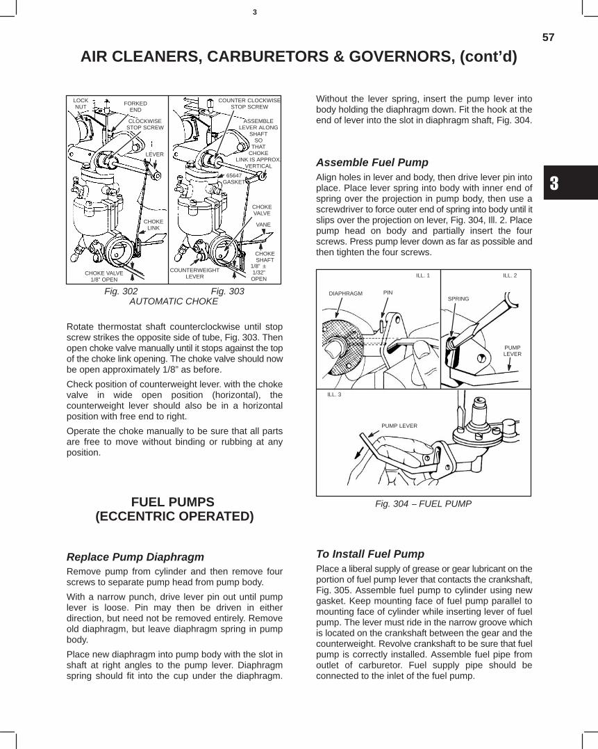
57
3
AIR CLEANERS, CARBURETORS & GOVERNORS, (cont’d)
AUTOMATIC CHOKEFig. 302 Fig. 303
FORKEDEND
CLOCKWISESTOP SCREW
LEVER
CHOKELINK
CHOKE VALVE1/8” OPEN
LOCKNUT
COUNTER CLOCKWISESTOP SCREW
ASSEMBLELEVER ALONG
SHAFTSO
THATCHOKE
LINK IS APPROX.VERTICAL
65647GASKET
VANE
CHOKESHAFT
1/8” 1/32”
OPEN
CHOKEVALVE
COUNTERWEIGHTLEVER
Rotate thermostat shaft counterclockwise until stopscrew strikes the opposite side of tube, Fig. 303. Thenopen choke valve manually until it stops against the topof the choke link opening. The choke valve should nowbe open approximately 1/8” as before.
Check position of counterweight lever. with the chokevalve in wide open position (horizontal), thecounterweight lever should also be in a horizontalposition with free end to right.
Operate the choke manually to be sure that all partsare free to move without binding or rubbing at anyposition.
FUEL PUMPS (ECCENTRIC OPERATED)
Replace Pump DiaphragmRemove pump from cylinder and then remove fourscrews to separate pump head from pump body.
With a narrow punch, drive lever pin out until pumplever is loose. Pin may then be driven in eitherdirection, but need not be removed entirely. Removeold diaphragm, but leave diaphragm spring in pumpbody.
Place new diaphragm into pump body with the slot inshaft at right angles to the pump lever. Diaphragmspring should fit into the cup under the diaphragm.
Without the lever spring, insert the pump lever intobody holding the diaphragm down. Fit the hook at theend of lever into the slot in diaphragm shaft, Fig. 304.
Assemble Fuel PumpAlign holes in lever and body, then drive lever pin intoplace. Place lever spring into body with inner end ofspring over the projection in pump body, then use ascrewdriver to force outer end of spring into body until itslips over the projection on lever, Fig. 304, Ill. 2. Placepump head on body and partially insert the fourscrews. Press pump lever down as far as possible andthen tighten the four screws.
Fig. 304 − FUEL PUMP
ILL. 1 ILL. 2
ILL. 3
DIAPHRAGM PINSPRING
PUMPLEVER
PUMP LEVER
To Install Fuel PumpPlace a liberal supply of grease or gear lubricant on theportion of fuel pump lever that contacts the crankshaft,Fig. 305. Assemble fuel pump to cylinder using newgasket. Keep mounting face of fuel pump parallel tomounting face of cylinder while inserting lever of fuelpump. The lever must ride in the narrow groove whichis located on the crankshaft between the gear and thecounterweight. Revolve crankshaft to be sure that fuelpump is correctly installed. Assemble fuel pipe fromoutlet of carburetor. Fuel supply pipe should beconnected to the inlet of the fuel pump.
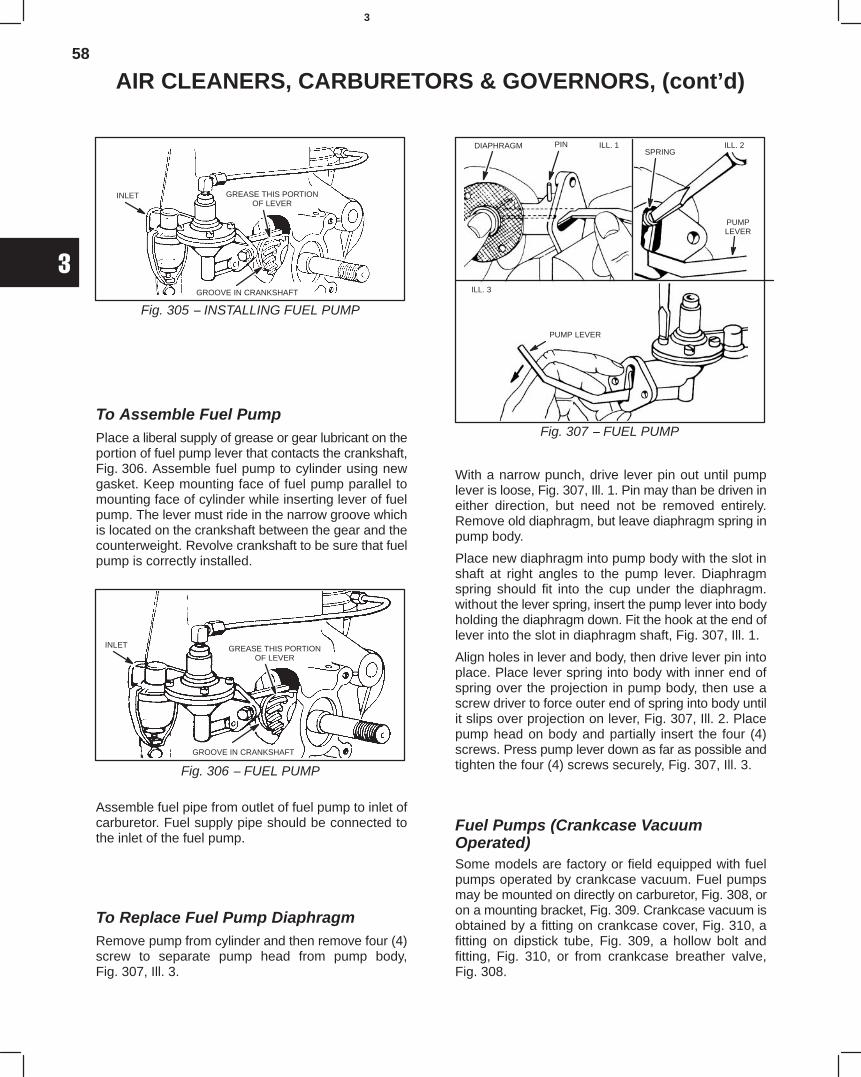
58
3
AIR CLEANERS, CARBURETORS & GOVERNORS, (cont’d)
Fig. 305 − INSTALLING FUEL PUMP
INLET GREASE THIS PORTIONOF LEVER
GROOVE IN CRANKSHAFT
To Assemble Fuel PumpPlace a liberal supply of grease or gear lubricant on theportion of fuel pump lever that contacts the crankshaft,Fig. 306. Assemble fuel pump to cylinder using newgasket. Keep mounting face of fuel pump parallel tomounting face of cylinder while inserting lever of fuelpump. The lever must ride in the narrow groove whichis located on the crankshaft between the gear and thecounterweight. Revolve crankshaft to be sure that fuelpump is correctly installed.
Fig. 306 − FUEL PUMP
INLET GREASE THIS PORTIONOF LEVER
GROOVE IN CRANKSHAFT
Assemble fuel pipe from outlet of fuel pump to inlet ofcarburetor. Fuel supply pipe should be connected tothe inlet of the fuel pump.
To Replace Fuel Pump DiaphragmRemove pump from cylinder and then remove four (4)screw to separate pump head from pump body,Fig. 307, Ill. 3.
Fig. 307 − FUEL PUMP
ILL. 1 ILL. 2
ILL. 3
DIAPHRAGM PINSPRING
PUMPLEVER
PUMP LEVER
With a narrow punch, drive lever pin out until pumplever is loose, Fig. 307, Ill. 1. Pin may than be driven ineither direction, but need not be removed entirely.Remove old diaphragm, but leave diaphragm spring inpump body.
Place new diaphragm into pump body with the slot inshaft at right angles to the pump lever. Diaphragmspring should fit into the cup under the diaphragm.without the lever spring, insert the pump lever into bodyholding the diaphragm down. Fit the hook at the end oflever into the slot in diaphragm shaft, Fig. 307, Ill. 1.
Align holes in lever and body, then drive lever pin intoplace. Place lever spring into body with inner end ofspring over the projection in pump body, then use ascrew driver to force outer end of spring into body untilit slips over projection on lever, Fig. 307, Ill. 2. Placepump head on body and partially insert the four (4)screws. Press pump lever down as far as possible andtighten the four (4) screws securely, Fig. 307, Ill. 3.
Fuel Pumps (Crankcase VacuumOperated)Some models are factory or field equipped with fuelpumps operated by crankcase vacuum. Fuel pumpsmay be mounted on directly on carburetor, Fig. 308, oron a mounting bracket, Fig. 309. Crankcase vacuum isobtained by a fitting on crankcase cover, Fig. 310, afitting on dipstick tube, Fig. 309, a hollow bolt andfitting, Fig. 310, or from crankcase breather valve,Fig. 308.
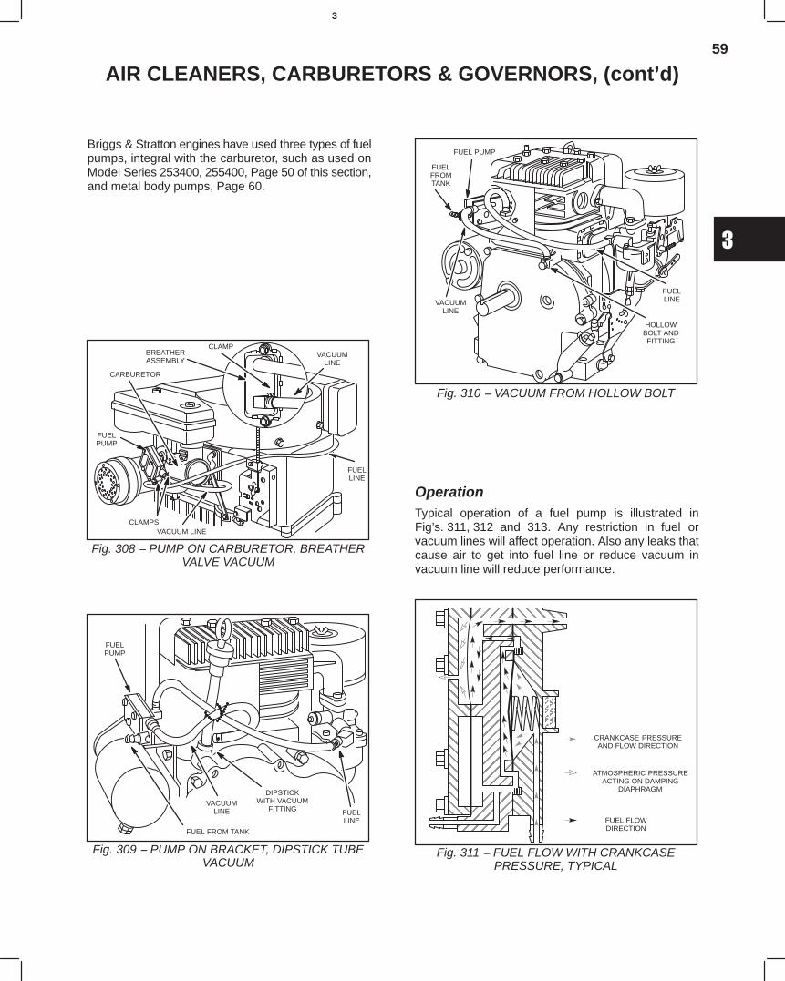
59
3
AIR CLEANERS, CARBURETORS & GOVERNORS, (cont’d)
Briggs & Stratton engines have used three types of fuelpumps, integral with the carburetor, such as used onModel Series 253400, 255400, Page 50 of this section,and metal body pumps, Page 60.
Fig. 308 − PUMP ON CARBURETOR, BREATHERVALVE VACUUM
FUELPUMP
CARBURETOR
VACUUM LINECLAMPS
FUELLINE
VACUUMLINE
CLAMPBREATHERASSEMBLY
Fig. 309 − PUMP ON BRACKET, DIPSTICK TUBEVACUUM
FUELLINE
DIPSTICKWITH VACUUM
FITTINGVACUUM
LINE
FUEL FROM TANK
FUELPUMP
Fig. 310 − VACUUM FROM HOLLOW BOLT
FUEL PUMP
FUELFROMTANK
VACUUMLINE
HOLLOWBOLT ANDFITTING
FUELLINE
OperationTypical operation of a fuel pump is illustrated inFig’s. 311, 312 and 313. Any restriction in fuel orvacuum lines will affect operation. Also any leaks thatcause air to get into fuel line or reduce vacuum invacuum line will reduce performance.
Fig. 311 − FUEL FLOW WITH CRANKCASEPRESSURE, TYPICAL
CRANKCASE PRESSUREAND FLOW DIRECTION
ATMOSPHERIC PRESSUREACTING ON DAMPING
DIAPHRAGM
É
ÇÇÇÇÇÇÇÇÇÇ
ÇÇÇÇÇÇÇÇÇÇÇÇÇÇÇÇÇÇÇÇÇÇÇÇÇÇÇÇÇÇÇÇÇÇÇÇÇÇÇÇÇÇÇÇÇÇÇÇÇÇÇÇÇÇÇÇ
ÉÉÉÉÉÉÉÉÉÉÉÉ
ÇÇÇÇÇÇÇÇÇÇÇÇÇÇÇÇ
ÉÉÉÉÉÉÉÉÉÉÉÉÉÉÉÉÉÉÉÉÉÉÉÉÉÉÉ
ÂÂÂÇÇ
ÇÇÇÇÇÇÇÇÇÇ
ÉÉ
ÉÉÉÉÉÉÉÉÉÉÉÉ
ÉÉÉÉÉÉÉÉÉ
FUEL FLOWDIRECTION
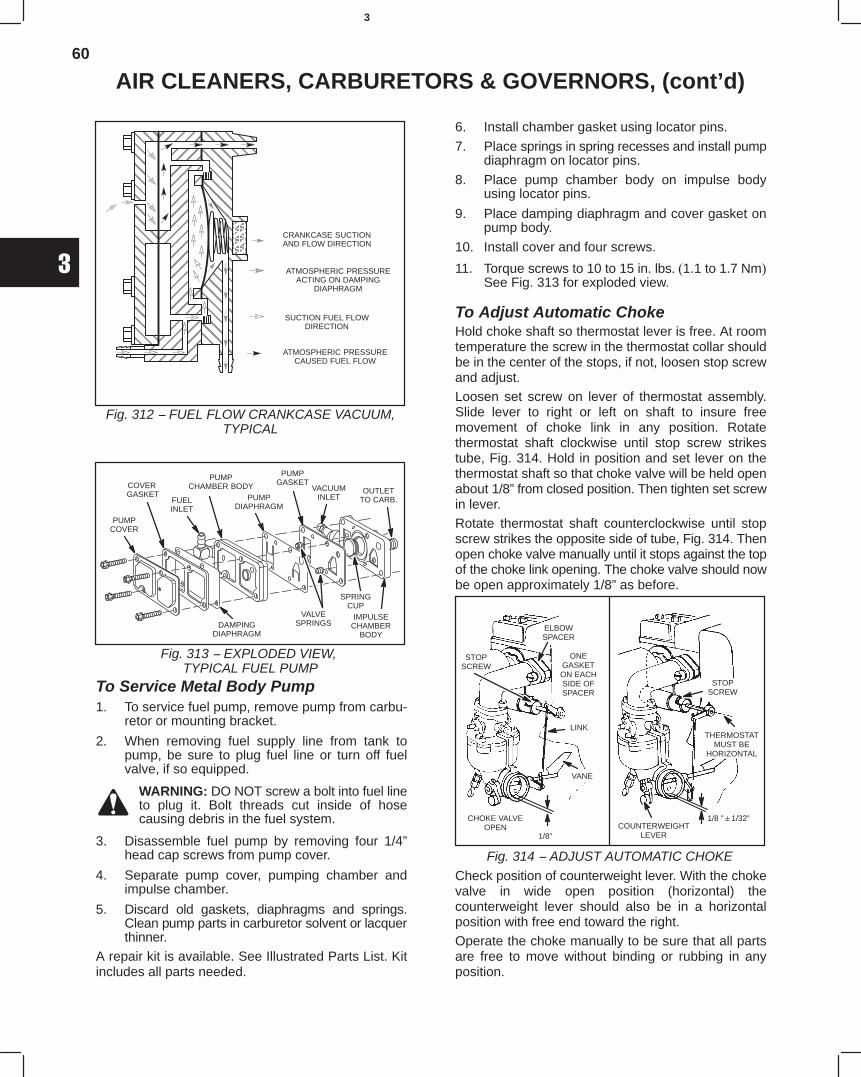
60
3
AIR CLEANERS, CARBURETORS & GOVERNORS, (cont’d)
Fig. 312 − FUEL FLOW CRANKCASE VACUUM,TYPICAL
ÉÉ
ÇÇÇÇÇÇÇÇ
ÇÇÇÇÇÇÇÇÇÇÇÇÇÇÇÇÇÇÇÇÇÇÇÇÇÇÇÇÇÇÇÇÇÇÇÇÇÇÇÇÇÇÇÇÇÇÇÇ
ÉÉÉÉÉ
ÇÇÇÇÇÇÇÇÇÇÇÇÇÇ
ÉÉÉÉÉÉÉÉÉÉÉÉÉÉÉÉÉÉÉÉÉÉÉÉ
ÂÂÂÂÂÂÇÇ
ÇÇÇÇÇÇÇÇÇÇ
ÉÉÉÉÉÉÉÉÉÉ
ÉÉÉÉÉÉ
CRANKCASE SUCTIONAND FLOW DIRECTION
ATMOSPHERIC PRESSUREACTING ON DAMPING
DIAPHRAGM
SUCTION FUEL FLOWDIRECTION
ATMOSPHERIC PRESSURECAUSED FUEL FLOW
Fig. 313 − EXPLODED VIEW, TYPICAL FUEL PUMP
PUMPCOVER
COVER GASKET
FUELINLET
PUMPDIAPHRAGM
PUMPCHAMBER BODY
VALVESPRINGS
SPRINGCUP
IMPULSECHAMBER
BODYDAMPING
DIAPHRAGM
PUMPGASKET
VACUUMINLET
OUTLETTO CARB.
To Service Metal Body Pump1. To service fuel pump, remove pump from carbu-
retor or mounting bracket.
2. When removing fuel supply line from tank topump, be sure to plug fuel line or turn off fuelvalve, if so equipped.
WARNING: DO NOT screw a bolt into fuel lineto plug it. Bolt threads cut inside of hosecausing debris in the fuel system.
3. Disassemble fuel pump by removing four 1/4”head cap screws from pump cover.
4. Separate pump cover, pumping chamber andimpulse chamber.
5. Discard old gaskets, diaphragms and springs.Clean pump parts in carburetor solvent or lacquerthinner.
A repair kit is available. See Illustrated Parts List. Kitincludes all parts needed.
6. Install chamber gasket using locator pins.
7. Place springs in spring recesses and install pumpdiaphragm on locator pins.
8. Place pump chamber body on impulse bodyusing locator pins.
9. Place damping diaphragm and cover gasket onpump body.
10. Install cover and four screws.
11. Torque screws to 10 to 15 in. lbs. (1.1 to 1.7 Nm)See Fig. 313 for exploded view.
To Adjust Automatic ChokeHold choke shaft so thermostat lever is free. At roomtemperature the screw in the thermostat collar shouldbe in the center of the stops, if not, loosen stop screwand adjust.Loosen set screw on lever of thermostat assembly.Slide lever to right or left on shaft to insure freemovement of choke link in any position. Rotatethermostat shaft clockwise until stop screw strikestube, Fig. 314. Hold in position and set lever on thethermostat shaft so that choke valve will be held openabout 1/8” from closed position. Then tighten set screwin lever.Rotate thermostat shaft counterclockwise until stopscrew strikes the opposite side of tube, Fig. 314. Thenopen choke valve manually until it stops against the topof the choke link opening. The choke valve should nowbe open approximately 1/8” as before.
Fig. 314 − ADJUST AUTOMATIC CHOKE
STOPSCREW
ELBOWSPACER
ONEGASKETON EACHSIDE OFSPACER
LINK
VANE
1/8”
CHOKE VALVEOPEN
STOPSCREW
THERMOSTATMUST BE
HORIZONTAL
COUNTERWEIGHTLEVER
1/8 ”1/32”
Check position of counterweight lever. With the chokevalve in wide open position (horizontal) thecounterweight lever should also be in a horizontalposition with free end toward the right.Operate the choke manually to be sure that all partsare free to move without binding or rubbing in anyposition.
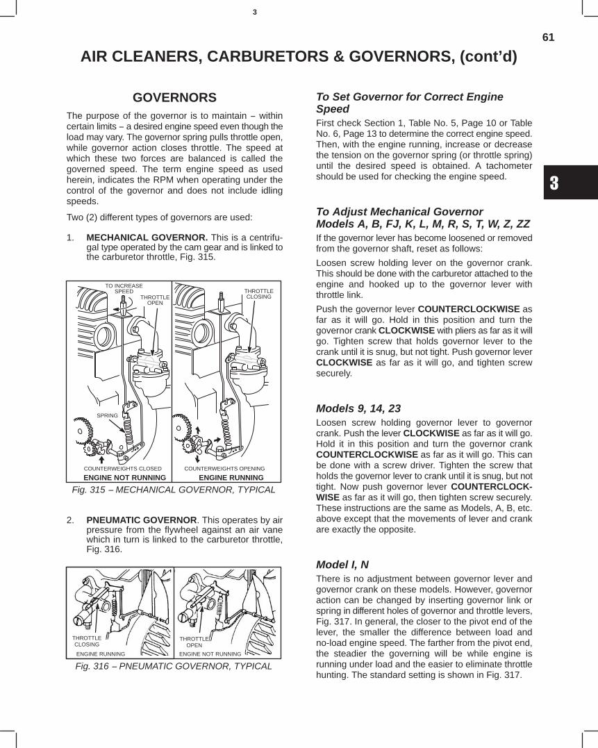
61
3
AIR CLEANERS, CARBURETORS & GOVERNORS, (cont’d)
GOVERNORSThe purpose of the governor is to maintain − withincertain limits − a desired engine speed even though theload may vary. The governor spring pulls throttle open,while governor action closes throttle. The speed atwhich these two forces are balanced is called thegoverned speed. The term engine speed as usedherein, indicates the RPM when operating under thecontrol of the governor and does not include idlingspeeds.
Two (2) different types of governors are used:
1. MECHANICAL GOVERNOR. This is a centrifu-gal type operated by the cam gear and is linked tothe carburetor throttle, Fig. 315.
Fig. 315 − MECHANICAL GOVERNOR, TYPICALENGINE NOT RUNNING ENGINE RUNNING
THROTTLEOPEN
THROTTLECLOSING
TO INCREASESPEED
COUNTERWEIGHTS OPENINGCOUNTERWEIGHTS CLOSED
SPRING
2. PNEUMATIC GOVERNOR. This operates by airpressure from the flywheel against an air vanewhich in turn is linked to the carburetor throttle,Fig. 316.
Fig. 316 − PNEUMATIC GOVERNOR, TYPICAL
THROTTLECLOSING
ENGINE RUNNING
THROTTLEOPEN
ENGINE NOT RUNNING
To Set Governor for Correct EngineSpeedFirst check Section 1, Table No. 5, Page 10 or TableNo. 6, Page 13 to determine the correct engine speed.Then, with the engine running, increase or decreasethe tension on the governor spring (or throttle spring)until the desired speed is obtained. A tachometershould be used for checking the engine speed.
To Adjust Mechanical GovernorModels A, B, FJ, K, L, M, R, S, T, W, Z, ZZIf the governor lever has become loosened or removedfrom the governor shaft, reset as follows:
Loosen screw holding lever on the governor crank.This should be done with the carburetor attached to theengine and hooked up to the governor lever withthrottle link.
Push the governor lever COUNTERCLOCKWISE asfar as it will go. Hold in this position and turn thegovernor crank CLOCKWISE with pliers as far as it willgo. Tighten screw that holds governor lever to thecrank until it is snug, but not tight. Push governor leverCLOCKWISE as far as it will go, and tighten screwsecurely.
Models 9, 14, 23Loosen screw holding governor lever to governorcrank. Push the lever CLOCKWISE as far as it will go.Hold it in this position and turn the governor crankCOUNTERCLOCKWISE as far as it will go. This canbe done with a screw driver. Tighten the screw thatholds the governor lever to crank until it is snug, but nottight. Now push governor lever COUNTERCLOCK-WISE as far as it will go, then tighten screw securely.These instructions are the same as Models, A, B, etc.above except that the movements of lever and crankare exactly the opposite.
Model I, NThere is no adjustment between governor lever andgovernor crank on these models. However, governoraction can be changed by inserting governor link orspring in different holes of governor and throttle levers,Fig. 317. In general, the closer to the pivot end of thelever, the smaller the difference between load andno-load engine speed. The farther from the pivot end,the steadier the governing will be while engine isrunning under load and the easier to eliminate throttlehunting. The standard setting is shown in Fig. 317.
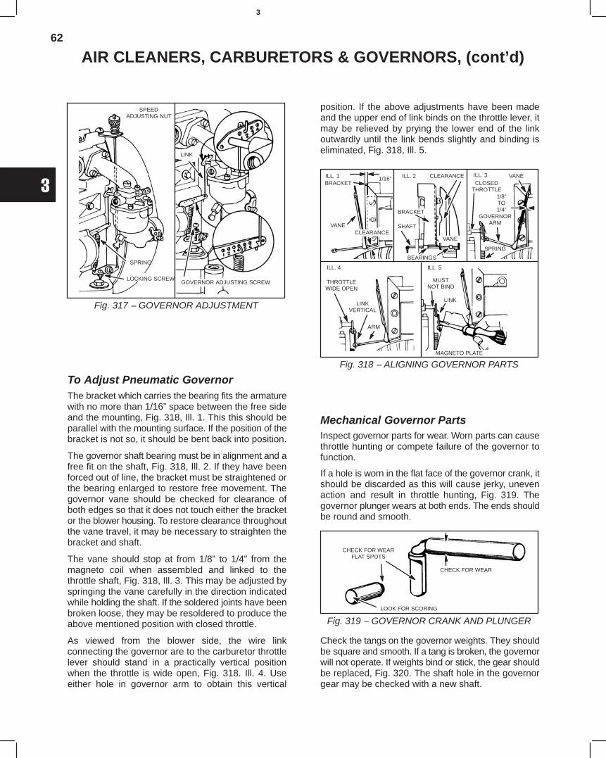
62
3
AIR CLEANERS, CARBURETORS & GOVERNORS, (cont’d)
Fig. 317 − GOVERNOR ADJUSTMENT
SPEEDADJUSTING NUT
SPRING
LOCKING SCREW
LINK
GOVERNOR ADJUSTING SCREW
To Adjust Pneumatic GovernorThe bracket which carries the bearing fits the armaturewith no more than 1/16” space between the free sideand the mounting, Fig. 318, Ill. 1. This this should beparallel with the mounting surface. If the position of thebracket is not so, it should be bent back into position.
The governor shaft bearing must be in alignment and afree fit on the shaft, Fig. 318, Ill. 2. If they have beenforced out of line, the bracket must be straightened orthe bearing enlarged to restore free movement. Thegovernor vane should be checked for clearance ofboth edges so that it does not touch either the bracketor the blower housing. To restore clearance throughoutthe vane travel, it may be necessary to straighten thebracket and shaft.
The vane should stop at from 1/8” to 1/4” from themagneto coil when assembled and linked to thethrottle shaft, Fig. 318, Ill. 3. This may be adjusted byspringing the vane carefully in the direction indicatedwhile holding the shaft. If the soldered joints have beenbroken loose, they may be resoldered to produce theabove mentioned position with closed throttle.
As viewed from the blower side, the wire linkconnecting the governor are to the carburetor throttlelever should stand in a practically vertical positionwhen the throttle is wide open, Fig. 318. Ill. 4. Useeither hole in governor arm to obtain this vertical
position. If the above adjustments have been madeand the upper end of link binds on the throttle lever, itmay be relieved by prying the lower end of the linkoutwardly until the link bends slightly and binding iseliminated, Fig. 318, Ill. 5.
Fig. 318 − ALIGNING GOVERNOR PARTS
ILL. 1 ILL. 2 ILL. 3
ILL. 4 ILL. 5
BRACKET1/16”
VANECLEARANCE
CLEARANCE
BRACKET
SHAFT
VANE
BEARINGS
VANECLOSED
THROTTLE1/8”TO1/4”
GOVERNORARM
SPRING
THROTTLEWIDE OPEN
LINKVERTICAL
ARM
MUSTNOT BIND
LINK
MAGNETO PLATE
Mechanical Governor PartsInspect governor parts for wear. Worn parts can causethrottle hunting or compete failure of the governor tofunction.
If a hole is worn in the flat face of the governor crank, itshould be discarded as this will cause jerky, unevenaction and result in throttle hunting, Fig. 319. Thegovernor plunger wears at both ends. The ends shouldbe round and smooth.
Fig. 319 − GOVERNOR CRANK AND PLUNGER
CHECK FOR WEARFLAT SPOTS
CHECK FOR WEAR
LOOK FOR SCORING
Check the tangs on the governor weights. They shouldbe square and smooth. If a tang is broken, the governorwill not operate. If weights bind or stick, the gear shouldbe replaced, Fig. 320. The shaft hole in the governorgear may be checked with a new shaft.
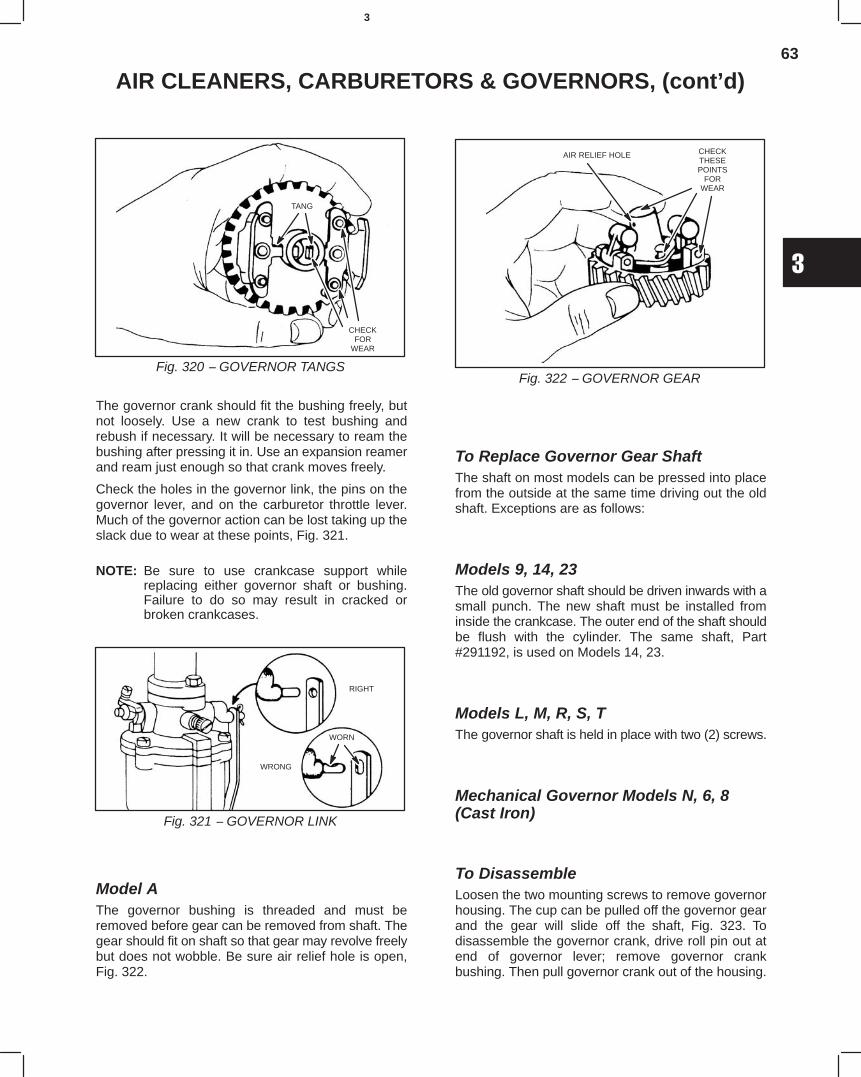
63
3
AIR CLEANERS, CARBURETORS & GOVERNORS, (cont’d)
Fig. 320 − GOVERNOR TANGS
TANG
CHECKFOR
WEAR
The governor crank should fit the bushing freely, butnot loosely. Use a new crank to test bushing andrebush if necessary. It will be necessary to ream thebushing after pressing it in. Use an expansion reamerand ream just enough so that crank moves freely.
Check the holes in the governor link, the pins on thegovernor lever, and on the carburetor throttle lever.Much of the governor action can be lost taking up theslack due to wear at these points, Fig. 321.
NOTE: Be sure to use crankcase support whilereplacing either governor shaft or bushing.Failure to do so may result in cracked orbroken crankcases.
Fig. 321 − GOVERNOR LINK
RIGHT
WRONG
WORN
Model AThe governor bushing is threaded and must beremoved before gear can be removed from shaft. Thegear should fit on shaft so that gear may revolve freelybut does not wobble. Be sure air relief hole is open,Fig. 322.
Fig. 322 − GOVERNOR GEAR
AIR RELIEF HOLE CHECKTHESEPOINTS
FORWEAR
To Replace Governor Gear ShaftThe shaft on most models can be pressed into placefrom the outside at the same time driving out the oldshaft. Exceptions are as follows:
Models 9, 14, 23The old governor shaft should be driven inwards with asmall punch. The new shaft must be installed frominside the crankcase. The outer end of the shaft shouldbe flush with the cylinder. The same shaft, Part#291192, is used on Models 14, 23.
Models L, M, R, S, TThe governor shaft is held in place with two (2) screws.
Mechanical Governor Models N, 6, 8(Cast Iron)
To DisassembleLoosen the two mounting screws to remove governorhousing. The cup can be pulled off the governor gearand the gear will slide off the shaft, Fig. 323. Todisassemble the governor crank, drive roll pin out atend of governor lever; remove governor crankbushing. Then pull governor crank out of the housing.
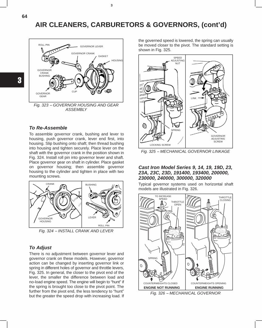
64
3
AIR CLEANERS, CARBURETORS & GOVERNORS, (cont’d)
Fig. 323 − GOVERNOR HOUSING AND GEARASSEMBLY
ROLL PINGOVERNOR LEVER
GOVERNOR CRANKGASKET
GOVERNORCRANK
BUSHING
GOVERNORGEAR
CUP
HOUSING
To Re-AssembleTo assemble governor crank, bushing and lever tohousing, push governor crank, lever end first, intohousing. Slip bushing onto shaft; then thread bushinginto housing and tighten securely. Place lever on theshaft with the governor crank in the position shown inFig. 324. Install roll pin into governor lever and shaft.Place governor gear on shaft in cylinder. Place gasketon governor housing; then assemble governorhousing to the cylinder and tighten in place with twomounting screws.
Fig. 324 − INSTALL CRANK AND LEVER
CRANK
GOVERNORHOUSING
BUSHING
LEVER
ROLL PIN
To AdjustThere is no adjustment between governor lever andgovernor crank on these models. However, governoraction can be changed by inserting governor link orspring in different holes of governor and throttle levers,Fig. 325. In general, the closer to the pivot end of thelever, the smaller the difference between load andno-load engine speed. The engine will begin to “hunt” ifthe spring is brought too close to the pivot point. Thefurther from the pivot end, the less tendency to “hunt”but the greater the speed drop with increasing load. If
the governed speed is lowered, the spring can usuallybe moved closer to the pivot. The standard setting isshown in Fig. 325.
Fig. 325 − MECHANICAL GOVERNOR LINKAGE
SPEEDADJUSTING
NUT
LOCKING SCREW
SPRING
LINK
GOVERNORADJUSTING
SCREW
Cast Iron Model Series 9, 14, 19, 19D, 23,23A, 23C, 23D, 191400, 193400, 200000,230000, 240000, 300000, 320000Typical governor systems used on horizontal shaftmodels are illustrated in Fig. 326.
Fig. 326 − MECHANICAL GOVERNORENGINE NOT RUNNING ENGINE RUNNING
THROTTLEOPEN
THROTTLECLOSING
TO INCREASESPEED
COUNTERWEIGHTS OPENINGCOUNTERWEIGHTS CLOSED
SPRING
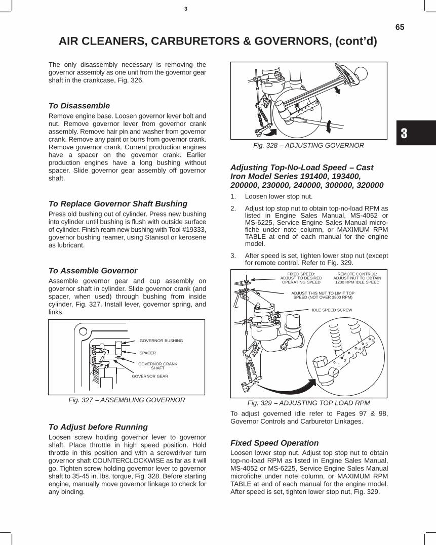
65
3
AIR CLEANERS, CARBURETORS & GOVERNORS, (cont’d)
The only disassembly necessary is removing thegovernor assembly as one unit from the governor gearshaft in the crankcase, Fig. 326.
To DisassembleRemove engine base. Loosen governor lever bolt andnut. Remove governor lever from governor crankassembly. Remove hair pin and washer from governorcrank. Remove any paint or burrs from governor crank.Remove governor crank. Current production engineshave a spacer on the governor crank. Earlierproduction engines have a long bushing withoutspacer. Slide governor gear assembly off governorshaft.
To Replace Governor Shaft BushingPress old bushing out of cylinder. Press new bushinginto cylinder until bushing is flush with outside surfaceof cylinder. Finish ream new bushing with Tool #19333,governor bushing reamer, using Stanisol or keroseneas lubricant.
To Assemble GovernorAssemble governor gear and cup assembly ongovernor shaft in cylinder. Slide governor crank (andspacer, when used) through bushing from insidecylinder, Fig. 327. Install lever, governor spring, andlinks.
Fig. 327 − ASSEMBLING GOVERNOR
GOVERNOR BUSHING
SPACER
GOVERNOR CRANKSHAFT
GOVERNOR GEAR
To Adjust before RunningLoosen screw holding governor lever to governorshaft. Place throttle in high speed position. Holdthrottle in this position and with a screwdriver turngovernor shaft COUNTERCLOCKWISE as far as it willgo. Tighten screw holding governor lever to governorshaft to 35-45 in. lbs. torque, Fig. 328. Before startingengine, manually move governor linkage to check forany binding.
Fig. 328 − ADJUSTING GOVERNOR
Adjusting Top-No-Load Speed − CastIron Model Series 191400, 193400,200000, 230000, 240000, 300000, 3200001. Loosen lower stop nut.
2. Adjust top stop nut to obtain top-no-load RPM aslisted in Engine Sales Manual, MS-4052 orMS-6225, Service Engine Sales Manual micro-fiche under note column, or MAXIMUM RPMTABLE at end of each manual for the enginemodel.
3. After speed is set, tighten lower stop nut (exceptfor remote control. Refer to Fig. 329.
Fig. 329 − ADJUSTING TOP LOAD RPM
FIXED SPEED:ADJUST TO DESIREDOPERATING SPEED
ADJUST THIS NUT TO LIMIT TOPSPEED (NOT OVER 3800 RPM)
REMOTE CONTROL:ADJUST NUT TO OBTAIN1200 RPM IDLE SPEED
IDLE SPEED SCREW
12
3
45
6
To adjust governed idle refer to Pages 97 & 98,Governor Controls and Carburetor Linkages.
Fixed Speed OperationLoosen lower stop nut. Adjust top stop nut to obtaintop-no-load RPM as listed in Engine Sales Manual,MS-4052 or MS-6225, Service Engine Sales Manualmicrofiche under note column, or MAXIMUM RPMTABLE at end of each manual for the engine model.After speed is set, tighten lower stop nut, Fig. 329.
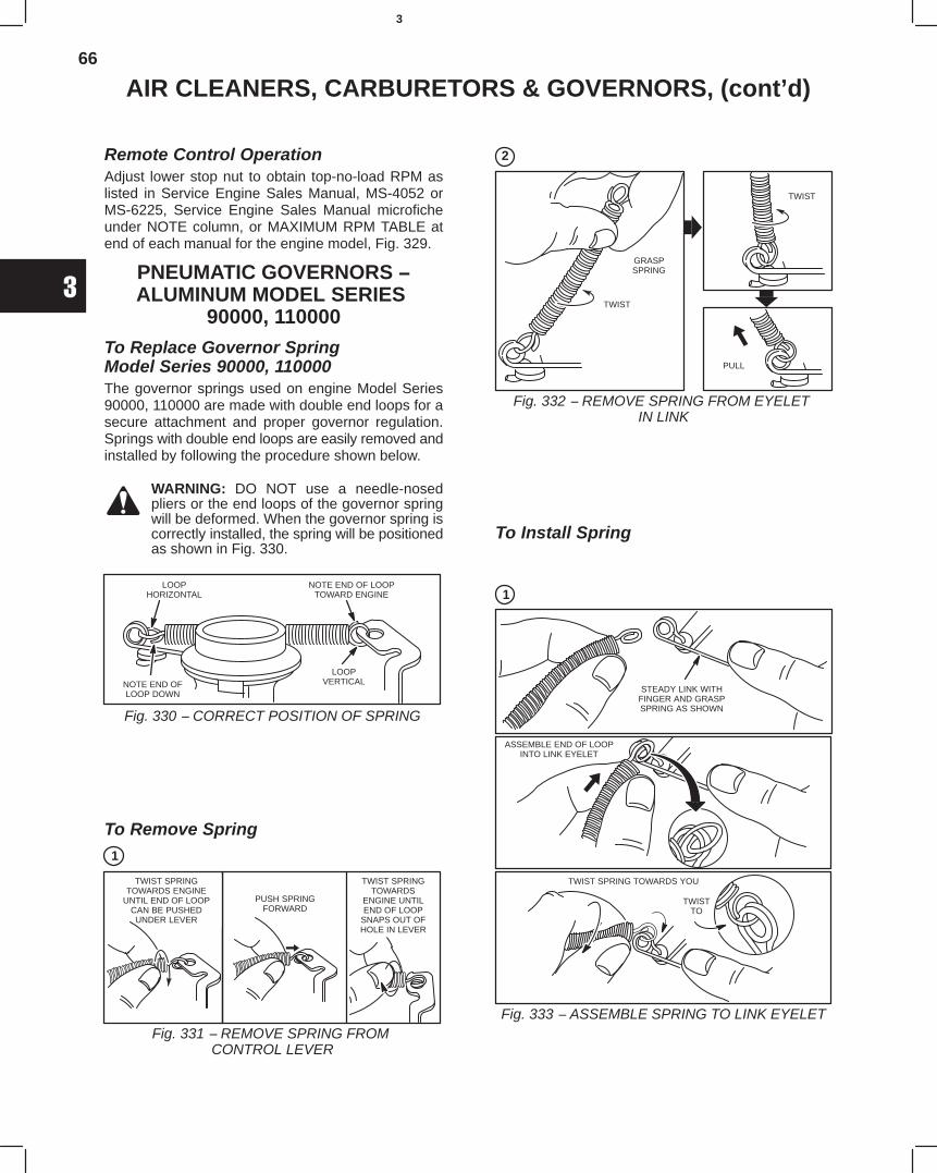
66
3
AIR CLEANERS, CARBURETORS & GOVERNORS, (cont’d)
Remote Control OperationAdjust lower stop nut to obtain top-no-load RPM aslisted in Service Engine Sales Manual, MS-4052 orMS-6225, Service Engine Sales Manual microficheunder NOTE column, or MAXIMUM RPM TABLE atend of each manual for the engine model, Fig. 329.
PNEUMATIC GOVERNORS −ALUMINUM MODEL SERIES
90000, 110000To Replace Governor SpringModel Series 90000, 110000The governor springs used on engine Model Series90000, 110000 are made with double end loops for asecure attachment and proper governor regulation.Springs with double end loops are easily removed andinstalled by following the procedure shown below.
WARNING: DO NOT use a needle-nosedpliers or the end loops of the governor springwill be deformed. When the governor spring iscorrectly installed, the spring will be positionedas shown in Fig. 330.
Fig. 330 − CORRECT POSITION OF SPRING
LOOPHORIZONTAL
NOTE END OFLOOP DOWN
LOOPVERTICAL
NOTE END OF LOOPTOWARD ENGINE
To Remove Spring1
Fig. 331 − REMOVE SPRING FROM CONTROL LEVER
TWIST SPRINGTOWARDS ENGINE
UNTIL END OF LOOPCAN BE PUSHEDUNDER LEVER
PUSH SPRINGFORWARD
TWIST SPRINGTOWARDS
ENGINE UNTILEND OF LOOP
SNAPS OUT OFHOLE IN LEVER
2
Fig. 332 − REMOVE SPRING FROM EYELET IN LINK
GRASPSPRING
TWIST
TWIST
PULL
To Install Spring
1
Fig. 333 − ASSEMBLE SPRING TO LINK EYELET
STEADY LINK WITHFINGER AND GRASPSPRING AS SHOWN
ASSEMBLE END OF LOOPINTO LINK EYELET
TWIST SPRING TOWARDS YOU
TWISTTO
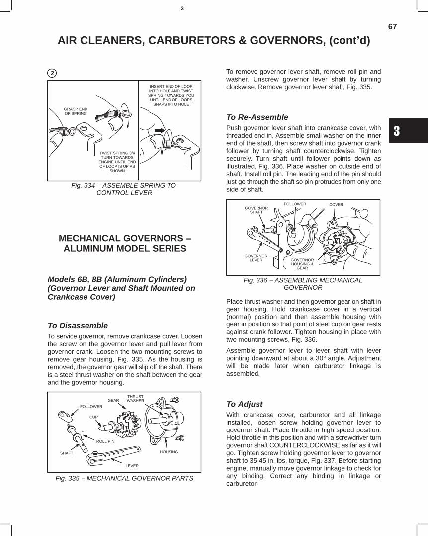
67
3
AIR CLEANERS, CARBURETORS & GOVERNORS, (cont’d)
2
Fig. 334 − ASSEMBLE SPRING TO CONTROL LEVER
GRASP ENDOF SPRING
TWIST SPRING 3/4TURN TOWARDS
ENGINE UNTIL ENDOF LOOP IS UP AS
SHOWN
INSERT END OF LOOPINTO HOLE AND TWISTSPRING TOWARDS YOUUNTIL END OF LOOPS
SNAPS INTO HOLE
MECHANICAL GOVERNORS −ALUMINUM MODEL SERIES
Models 6B, 8B (Aluminum Cylinders)(Governor Lever and Shaft Mounted onCrankcase Cover)
To DisassembleTo service governor, remove crankcase cover. Loosenthe screw on the governor lever and pull lever fromgovernor crank. Loosen the two mounting screws toremove gear housing, Fig. 335. As the housing isremoved, the governor gear will slip off the shaft. Thereis a steel thrust washer on the shaft between the gearand the governor housing.
Fig. 335 − MECHANICAL GOVERNOR PARTS
FOLLOWER
CUP
ROLL PIN
SHAFT
LEVER
GEARTHRUSTWASHER
HOUSING
To remove governor lever shaft, remove roll pin andwasher. Unscrew governor lever shaft by turningclockwise. Remove governor lever shaft, Fig. 335.
To Re-AssemblePush governor lever shaft into crankcase cover, withthreaded end in. Assemble small washer on the innerend of the shaft, then screw shaft into governor crankfollower by turning shaft counterclockwise. Tightensecurely. Turn shaft until follower points down asillustrated, Fig. 336. Place washer on outside end ofshaft. Install roll pin. The leading end of the pin shouldjust go through the shaft so pin protrudes from only oneside of shaft.
Fig. 336 − ASSEMBLING MECHANICALGOVERNOR
GOVERNORSHAFT
FOLLOWER
GOVERNORLEVER
COVER
GOVERNORHOUSING &
GEAR
Place thrust washer and then governor gear on shaft ingear housing. Hold crankcase cover in a vertical(normal) position and then assemble housing withgear in position so that point of steel cup on gear restsagainst crank follower. Tighten housing in place withtwo mounting screws, Fig. 336.
Assemble governor lever to lever shaft with leverpointing downward at about a 30° angle. Adjustmentwill be made later when carburetor linkage isassembled.
To AdjustWith crankcase cover, carburetor and all linkageinstalled, loosen screw holding governor lever togovernor shaft. Place throttle in high speed position.Hold throttle in this position and with a screwdriver turngovernor shaft COUNTERCLOCKWISE as far as it willgo. Tighten screw holding governor lever to governorshaft to 35-45 in. lbs. torque, Fig. 337. Before startingengine, manually move governor linkage to check forany binding. Correct any binding in linkage orcarburetor.
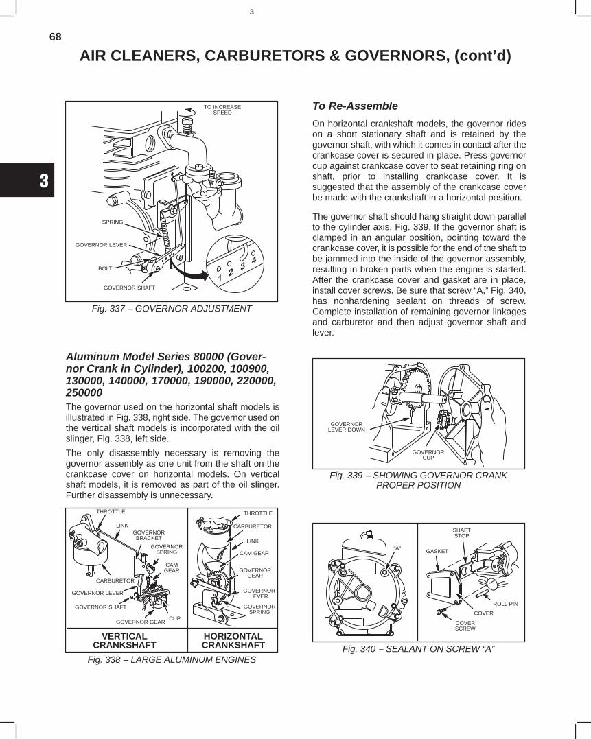
68
3
AIR CLEANERS, CARBURETORS & GOVERNORS, (cont’d)
Fig. 337 − GOVERNOR ADJUSTMENT
TO INCREASESPEED
SPRING
GOVERNOR LEVER
GOVERNOR SHAFT
BOLT
Aluminum Model Series 80000 (Gover-nor Crank in Cylinder), 100200, 100900,130000, 140000, 170000, 190000, 220000,250000The governor used on the horizontal shaft models isillustrated in Fig. 338, right side. The governor used onthe vertical shaft models is incorporated with the oilslinger, Fig. 338, left side.
The only disassembly necessary is removing thegovernor assembly as one unit from the shaft on thecrankcase cover on horizontal models. On verticalshaft models, it is removed as part of the oil slinger.Further disassembly is unnecessary.
Fig. 338 − LARGE ALUMINUM ENGINES
HORIZONTALCRANKSHAFT
VERTICALCRANKSHAFT
THROTTLE
LINKGOVERNORBRACKET
GOVERNORSPRING
CAMGEAR
CUPGOVERNOR GEAR
CARBURETOR
GOVERNOR LEVER
GOVERNOR SHAFT
THROTTLE
CARBURETOR
LINK
CAM GEAR
GOVERNORGEAR
GOVERNORLEVER
GOVERNORSPRING
To Re-Assemble
On horizontal crankshaft models, the governor rideson a short stationary shaft and is retained by thegovernor shaft, with which it comes in contact after thecrankcase cover is secured in place. Press governorcup against crankcase cover to seat retaining ring onshaft, prior to installing crankcase cover. It issuggested that the assembly of the crankcase coverbe made with the crankshaft in a horizontal position.
The governor shaft should hang straight down parallelto the cylinder axis, Fig. 339. If the governor shaft isclamped in an angular position, pointing toward thecrankcase cover, it is possible for the end of the shaft tobe jammed into the inside of the governor assembly,resulting in broken parts when the engine is started.After the crankcase cover and gasket are in place,install cover screws. Be sure that screw “A,” Fig. 340,has nonhardening sealant on threads of screw.Complete installation of remaining governor linkagesand carburetor and then adjust governor shaft andlever.
Fig. 339 − SHOWING GOVERNOR CRANKPROPER POSITION
GOVERNORLEVER DOWN
GOVERNORCUP
Fig. 340 − SEALANT ON SCREW “A”
“A”
SHAFTSTOP
GASKET
ROLL PIN
COVER
COVERSCREW
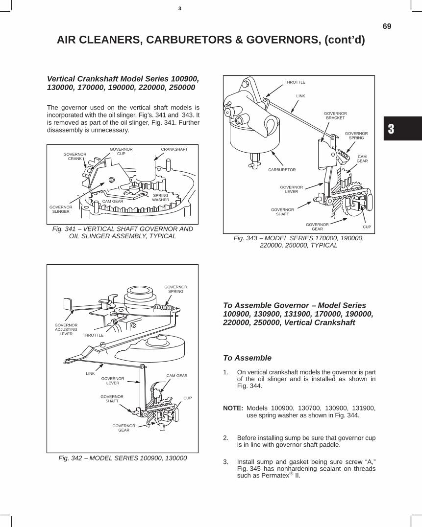
69
3
AIR CLEANERS, CARBURETORS & GOVERNORS, (cont’d)
Vertical Crankshaft Model Series 100900,130000, 170000, 190000, 220000, 2500004750The governor used on the vertical shaft models isincorporated with the oil slinger, Fig’s. 341 and 343. Itis removed as part of the oil slinger, Fig. 341. Furtherdisassembly is unnecessary. 4750
Fig. 341 − VERTICAL SHAFT GOVERNOR ANDOIL SLINGER ASSEMBLY, TYPICAL
CRANKSHAFT
SPRINGWASHERCAM GEAR
GOVERNORSLINGER
GOVERNORCUPGOVERNOR
CRANK
Fig. 342 − MODEL SERIES 100900, 130000
GOVERNORADJUSTING
LEVER
GOVERNORSPRING
THROTTLE
LINKGOVERNOR
LEVER
GOVERNORSHAFT
CAM GEAR
CUP
GOVERNORGEAR
Fig. 343 − MODEL SERIES 170000, 190000,220000, 250000, TYPICAL
THROTTLE
LINK
GOVERNORBRACKET
GOVERNORSPRING
CAMGEAR
CUPGOVERNOR
GEAR
CARBURETOR
GOVERNORLEVER
GOVERNORSHAFT
To Assemble Governor − Model Series100900, 130900, 131900, 170000, 190000,220000, 250000, Vertical Crankshaft 4750
To Assemble 4750
1. On vertical crankshaft models the governor is partof the oil slinger and is installed as shown inFig. 344. 4750
NOTE: Models 100900, 130700, 130900, 131900,use spring washer as shown in Fig. 344. 4750
2. Before installing sump be sure that governor cupis in line with governor shaft paddle. 4750
3. Install sump and gasket being sure screw “A,”Fig. 345 has nonhardening sealant on threadssuch as Permatex II. 4750
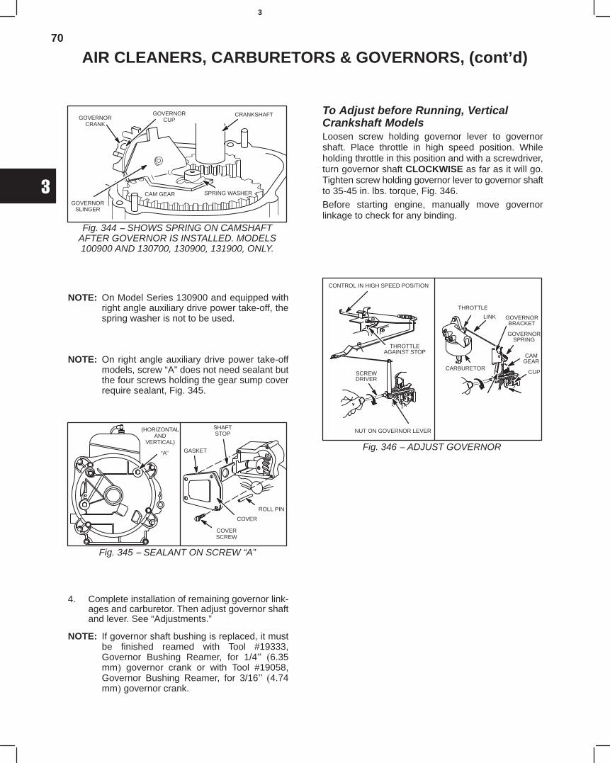
70
3
AIR CLEANERS, CARBURETORS & GOVERNORS, (cont’d)
Fig. 344 − SHOWS SPRING ON CAMSHAFTAFTER GOVERNOR IS INSTALLED. MODELS100900 AND 130700, 130900, 131900, ONLY.
CRANKSHAFT
SPRING WASHERCAM GEAR
GOVERNORSLINGER
GOVERNORCUPGOVERNOR
CRANK
NOTE: On Model Series 130900 and equipped withright angle auxiliary drive power take-off, thespring washer is not to be used. 4750
NOTE: On right angle auxiliary drive power take-offmodels, screw “A” does not need sealant butthe four screws holding the gear sump coverrequire sealant, Fig. 345. 4750
Fig. 345 − SEALANT ON SCREW “A”
“A”
SHAFTSTOP
GASKET
ROLL PIN
COVER
COVERSCREW
(HORIZONTALAND
VERTICAL)
4. Complete installation of remaining governor link-ages and carburetor. Then adjust governor shaftand lever. See “Adjustments.” 4750
NOTE: If governor shaft bushing is replaced, it mustbe finished reamed with Tool #19333,Governor Bushing Reamer, for 1/4" (6.35mm) governor crank or with Tool #19058,Governor Bushing Reamer, for 3/16" (4.74mm) governor crank. 4750
To Adjust before Running, VerticalCrankshaft ModelsLoosen screw holding governor lever to governorshaft. Place throttle in high speed position. Whileholding throttle in this position and with a screwdriver,turn governor shaft CLOCKWISE as far as it will go.Tighten screw holding governor lever to governor shaftto 35-45 in. lbs. torque, Fig. 346.
Before starting engine, manually move governorlinkage to check for any binding.
Fig. 346 − ADJUST GOVERNOR
THROTTLE
LINK GOVERNORBRACKET
GOVERNORSPRING
CAMGEAR
CUPCARBURETOR
CONTROL IN HIGH SPEED POSITION
THROTTLEAGAINST STOP
NUT ON GOVERNOR LEVER
SCREWDRIVER
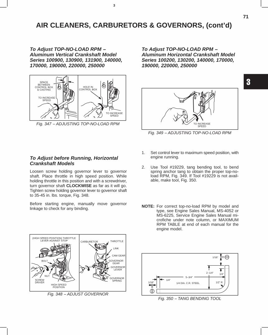
71
3
AIR CLEANERS, CARBURETORS & GOVERNORS, (cont’d)
To Adjust TOP-NO-LOAD RPM −Aluminum Vertical Crankshaft ModelSeries 100900, 130900, 131900, 140000,170000, 190000, 220000, 250000
Fig. 347 − ADJUSTING TOP-NO-LOAD RPM
SPACEBETWEEN
CONTROL BOX& CASTING
TO INCREASESPEED
TO INCREASESPEED
HOLE INCONTROL BOX
To Adjust before Running, HorizontalCrankshaft Models
Loosen screw holding governor lever to governorshaft. Place throttle in high speed position. Whileholding throttle in this position and with a screwdriver,turn governor shaft CLOCKWISE as far as it will go.Tighten screw holding governor lever to governor shaftto 35-45 in. lbs. torque, Fig. 348.
Before starting engine, manually move governorlinkage to check for any binding.
Fig. 348 − ADJUST GOVERNOR
(HIGH SPEED POSITION) THROTTLELEVER AGAINST STOP
BOLT
NUT
HIGH SPEEDPOSITION
SCREWDRIVER
THROTTLECARBURETOR
LINK
CAM GEAR
GOVERNORGEAR
GOVERNORLEVER
GOVERNORSPRING
To Adjust TOP-NO-LOAD RPM −Aluminum Horizontal Crankshaft ModelSeries 100200, 130200, 140000, 170000,190000, 220000, 250000
Fig. 349 − ADJUSTING TOP-NO-LOAD RPM
TO INCREASESPEED
1. Set control lever to maximum speed position, withengine running.
2. Use Tool #19229, tang bending tool, to bendspring anchor tang to obtain the proper top-no-load RPM, Fig. 349. If Tool #19229 is not avail-able, make tool, Fig. 350.
NOTE: For correct top-no-load RPM by model andtype, see Engine Sales Manual, MS-4052 orMS-6225, Service Engine Sales Manual mi-crofiche under note column, or MAXIMUMRPM TABLE at end of each manual for theengine model.
Fig. 350 − TANG BENDING TOOL
5−3/4”
2−1/4”
1/2” R
1/4”
1/16”
1/4”1/16” 1/4 DIA. C.R. STEEL
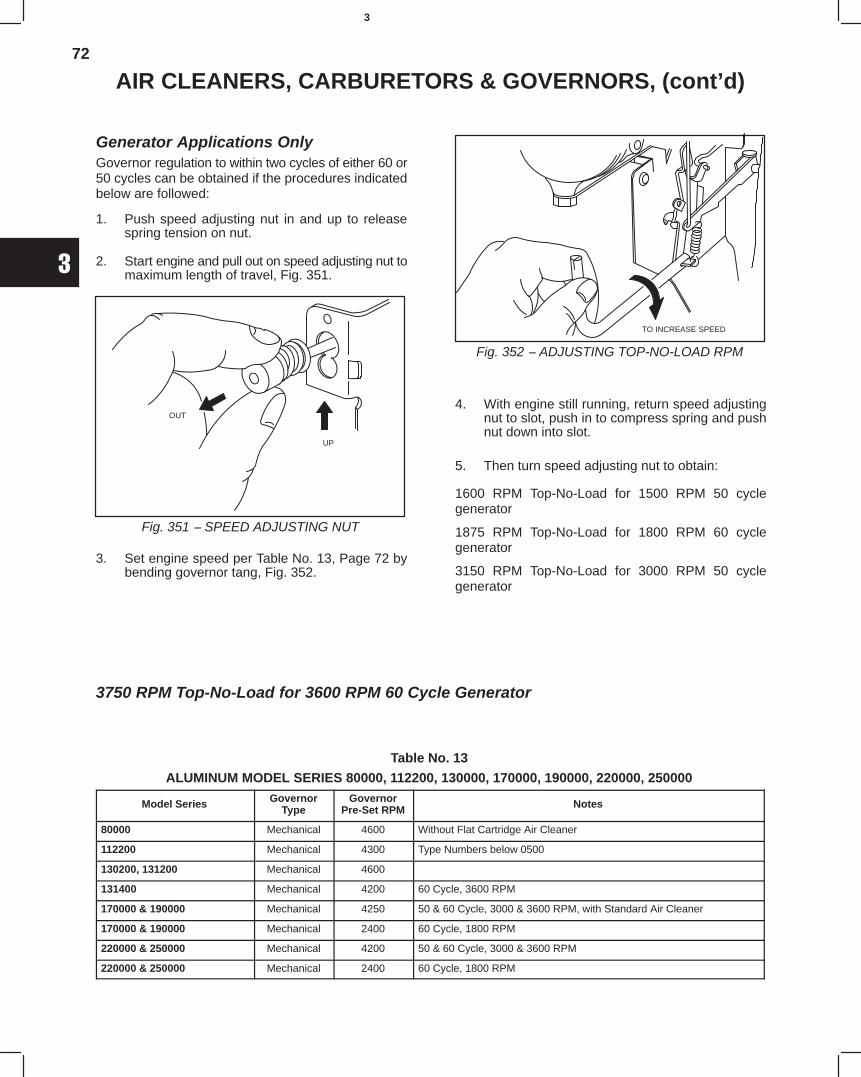
72
3
AIR CLEANERS, CARBURETORS & GOVERNORS, (cont’d)
Generator Applications OnlyGovernor regulation to within two cycles of either 60 or50 cycles can be obtained if the procedures indicatedbelow are followed:
1. Push speed adjusting nut in and up to releasespring tension on nut.
2. Start engine and pull out on speed adjusting nut tomaximum length of travel, Fig. 351.
Fig. 351 − SPEED ADJUSTING NUT
OUT
UP
3. Set engine speed per Table No. 13, Page 72 bybending governor tang, Fig. 352.
Fig. 352 − ADJUSTING TOP-NO-LOAD RPM
TO INCREASE SPEED
4. With engine still running, return speed adjustingnut to slot, push in to compress spring and pushnut down into slot.
5. Then turn speed adjusting nut to obtain:
1600 RPM Top-No-Load for 1500 RPM 50 cyclegenerator
1875 RPM Top-No-Load for 1800 RPM 60 cyclegenerator
3150 RPM Top-No-Load for 3000 RPM 50 cyclegenerator
3750 RPM Top-No-Load for 3600 RPM 60 Cycle Generator
Table No. 13
ALUMINUM MODEL SERIES 80000, 112200, 130000, 170000, 190000, 220000, 250000
Model Series GovernorType
GovernorPre-Set RPM Notes
80000 Mechanical 4600 Without Flat Cartridge Air Cleaner
112200 Mechanical 4300 Type Numbers below 0500
130200, 131200 Mechanical 4600
131400 Mechanical 4200 60 Cycle, 3600 RPM
170000 & 190000 Mechanical 4250 50 & 60 Cycle, 3000 & 3600 RPM, with Standard Air Cleaner
170000 & 190000 Mechanical 2400 60 Cycle, 1800 RPM
220000 & 250000 Mechanical 4200 50 & 60 Cycle, 3000 & 3600 RPM
220000 & 250000 Mechanical 2400 60 Cycle, 1800 RPM
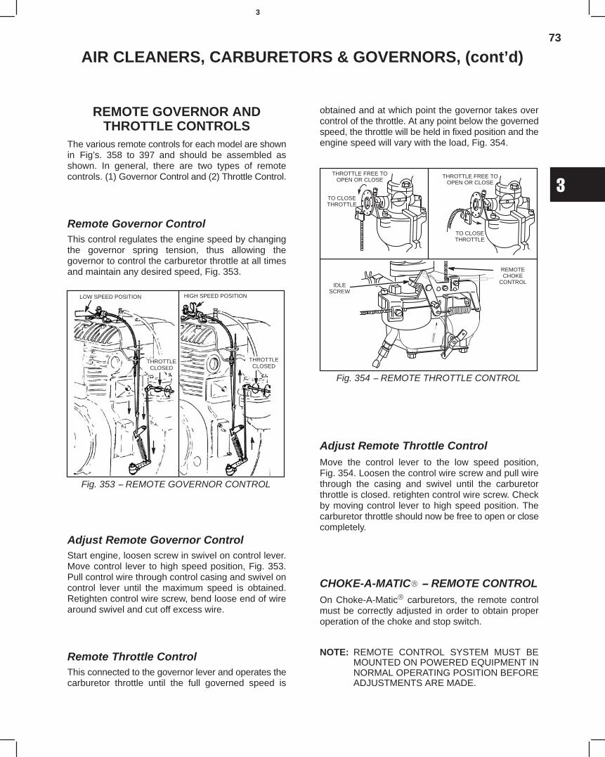
73
3
AIR CLEANERS, CARBURETORS & GOVERNORS, (cont’d)
REMOTE GOVERNOR ANDTHROTTLE CONTROLS
The various remote controls for each model are shownin Fig’s. 358 to 397 and should be assembled asshown. In general, there are two types of remotecontrols. (1) Governor Control and (2) Throttle Control.
Remote Governor ControlThis control regulates the engine speed by changingthe governor spring tension, thus allowing thegovernor to control the carburetor throttle at all timesand maintain any desired speed, Fig. 353.
Fig. 353 − REMOTE GOVERNOR CONTROL
LOW SPEED POSITION
THROTTLECLOSED
HIGH SPEED POSITION
THROTTLECLOSED
Adjust Remote Governor ControlStart engine, loosen screw in swivel on control lever.Move control lever to high speed position, Fig. 353.Pull control wire through control casing and swivel oncontrol lever until the maximum speed is obtained.Retighten control wire screw, bend loose end of wirearound swivel and cut off excess wire.
Remote Throttle ControlThis connected to the governor lever and operates thecarburetor throttle until the full governed speed is
obtained and at which point the governor takes overcontrol of the throttle. At any point below the governedspeed, the throttle will be held in fixed position and theengine speed will vary with the load, Fig. 354.
THROTTLE FREE TOOPEN OR CLOSE
TO CLOSETHROTTLE
THROTTLE FREE TOOPEN OR CLOSE
TO CLOSETHROTTLE
IDLESCREW
REMOTECHOKE
CONTROL
Fig. 354 − REMOTE THROTTLE CONTROL
Adjust Remote Throttle ControlMove the control lever to the low speed position,Fig. 354. Loosen the control wire screw and pull wirethrough the casing and swivel until the carburetorthrottle is closed. retighten control wire screw. Checkby moving control lever to high speed position. Thecarburetor throttle should now be free to open or closecompletely.
CHOKE-A-MATIC − REMOTE CONTROLOn Choke-A-Matic carburetors, the remote controlmust be correctly adjusted in order to obtain properoperation of the choke and stop switch.
NOTE: REMOTE CONTROL SYSTEM MUST BEMOUNTED ON POWERED EQUIPMENT INNORMAL OPERATING POSITION BEFOREADJUSTMENTS ARE MADE.
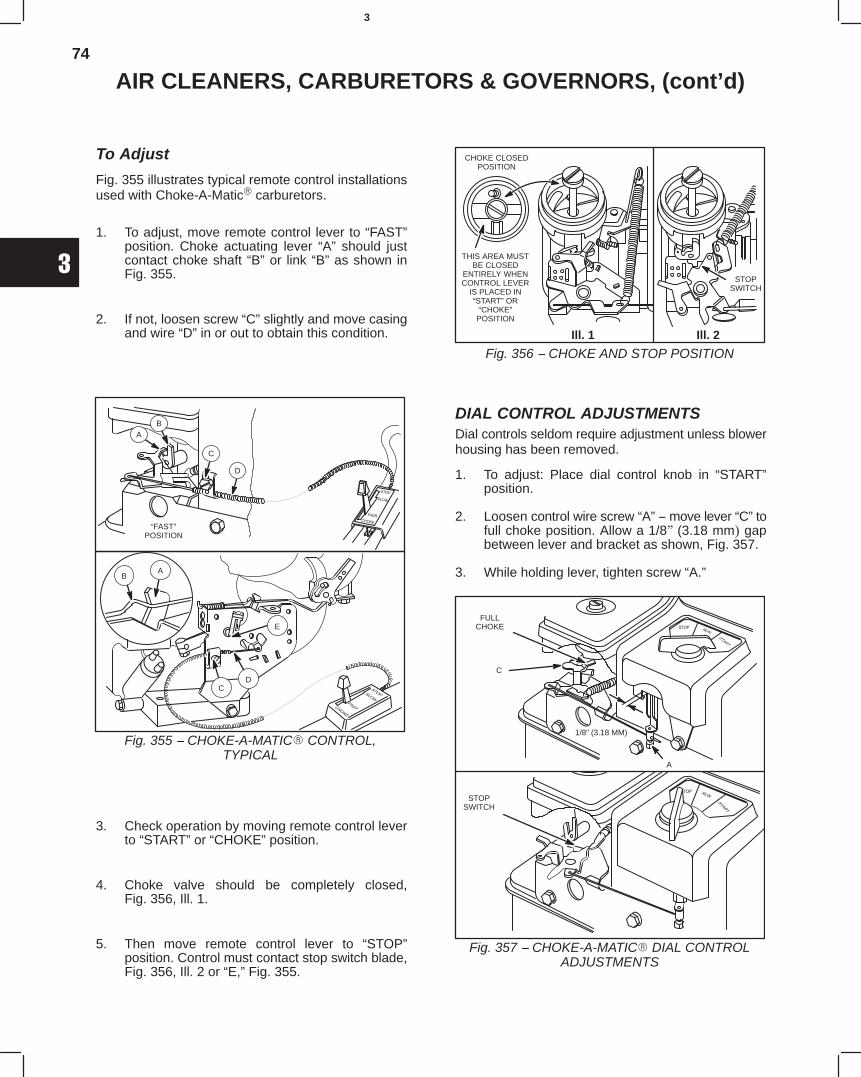
74
3
AIR CLEANERS, CARBURETORS & GOVERNORS, (cont’d)
To Adjust
Fig. 355 illustrates typical remote control installationsused with Choke-A-Matic carburetors.
1. To adjust, move remote control lever to “FAST”position. Choke actuating lever “A” should justcontact choke shaft “B” or link “B” as shown inFig. 355.
2. If not, loosen screw “C” slightly and move casingand wire “D” in or out to obtain this condition.
“FAST”POSITION
AB
C
D
AB
CD
Fig. 355 − CHOKE-A-MATIC CONTROL,TYPICAL
E
3. Check operation by moving remote control leverto “START” or “CHOKE” position.
4. Choke valve should be completely closed,Fig. 356, Ill. 1.
5. Then move remote control lever to “STOP”position. Control must contact stop switch blade,Fig. 356, Ill. 2 or “E,” Fig. 355.
CHOKE CLOSEDPOSITION
THIS AREA MUSTBE CLOSED
ENTIRELY WHENCONTROL LEVER
IS PLACED IN“START” OR
“CHOKE”POSITION
STOPSWITCH
Fig. 356 − CHOKE AND STOP POSITIONIll. 1 Ill. 2
DIAL CONTROL ADJUSTMENTSDial controls seldom require adjustment unless blowerhousing has been removed.
1. To adjust: Place dial control knob in “START”position.
2. Loosen control wire screw “A” − move lever “C” tofull choke position. Allow a 1/8" (3.18 mm) gapbetween lever and bracket as shown, Fig. 357.
3. While holding lever, tighten screw “A.”
FULLCHOKE
STOPSWITCH
A
C
Fig. 357 − CHOKE-A-MATIC DIAL CONTROLADJUSTMENTS
1/8” (3.18 MM)
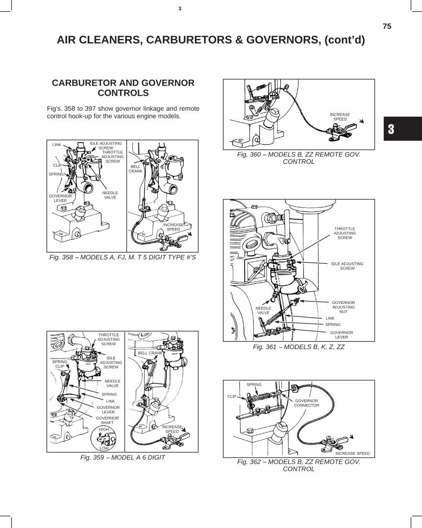
75
3
AIR CLEANERS, CARBURETORS & GOVERNORS, (cont’d)
CARBURETOR AND GOVERNORCONTROLS
Fig’s. 358 to 397 show governor linkage and remotecontrol hook-up for the various engine models.
Fig. 358 − MODELS A, FJ, M. T 5 DIGIT TYPE #’S
LINK IDLE ADJUSTINGSCREW
THROTTLEADJUSTING
SCREW
NEEDLEVALVE
CLIP
SPRING
GOVERNORLEVER
BELLCRANK
INCREASESPEED
Fig. 359 − MODEL A 6 DIGIT
THROTTLEADJUSTING
SCREW
IDLEADJUSTING
SCREWSPRING
CLIP
NEEDLEVALVE
SPRING
LINK
GOVERNORLEVER
GOVERNORSHAFT
HIGH
LOW
BELL CRANK
INCREASESPEED
Fig. 360 − MODELS B, ZZ REMOTE GOV.CONTROL
INCREASESPEED
Fig. 361 − MODELS B, K, Z, ZZ
THROTTLEADJUSTING
SCREW
IDLE ADJUSTINGSCREW
NEEDLEVALVE
GOVERNORADJUSTING
NUT
LINK
SPRING
GOVERNORLEVER
Fig. 362 − MODELS B, ZZ REMOTE GOV.CONTROL
INCREASE SPEED
GOVERNORCONNECTOR
SPRING
CLIP
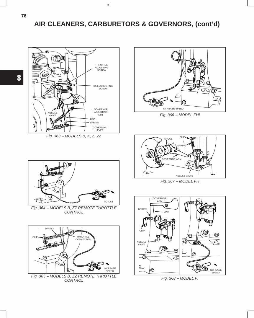
76
3
AIR CLEANERS, CARBURETORS & GOVERNORS, (cont’d)
Fig. 363 − MODELS B, K, Z, ZZ
THROTTLEADJUSTING
SCREW
IDLE ADJUSTINGSCREW
NEEDLEVALVE
GOVERNORADJUSTING
NUT
LINK
SPRING
GOVERNORLEVER
Fig. 364 − MODELS B, ZZ REMOTE THROTTLECONTROL
TO IDLE
Fig. 365 − MODELS B, ZZ REMOTE THROTTLECONTROL
INCREASESPEED
THROTTLECONNECTOR
SPRING
CLIP
Fig. 366 − MODEL FHI
INCREASE SPEED
Fig. 367 − MODEL FH
SPOOLCLIP
SPRING
GOVERNOR ARM
NEEDLE VALVE
LINK
Fig. 368 − MODEL FI
GOVERNORARM
SPRINGLINK
CLIP
NEEDLEVALVE
INCREASESPEED
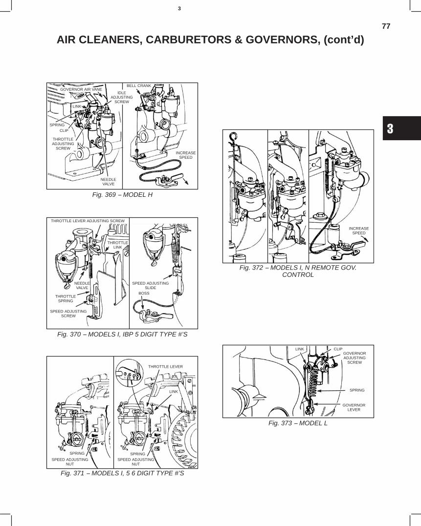
77
3
AIR CLEANERS, CARBURETORS & GOVERNORS, (cont’d)
Fig. 369 − MODEL H
GOVERNOR AIR VANE
THROTTLEADJUSTING
SCREW
IDLEADJUSTING
SCREW
NEEDLEVALVE
LINK
SPRING
CLIP
BELL CRANK
INCREASESPEED
Fig. 370 − MODELS I, IBP 5 DIGIT TYPE #’S
THROTTLE LEVER ADJUSTING SCREW
THROTTLELINK
NEEDLEVALVE
THROTTLESPRING
SPEED ADJUSTINGSCREW
SPEED ADJUSTINGSLIDE
BOSS
Fig. 371 − MODELS I, 5 6 DIGIT TYPE #’S
SPRING
SPEED ADJUSTINGNUT
THROTTLE LEVER
SPRING
SPEED ADJUSTINGNUT
LINK
Fig. 372 − MODELS I, N REMOTE GOV.CONTROL
INCREASESPEED
Fig. 373 − MODEL L
GOVERNORADJUSTING
SCREW
SPRING
GOVERNORLEVER
CLIPLINK
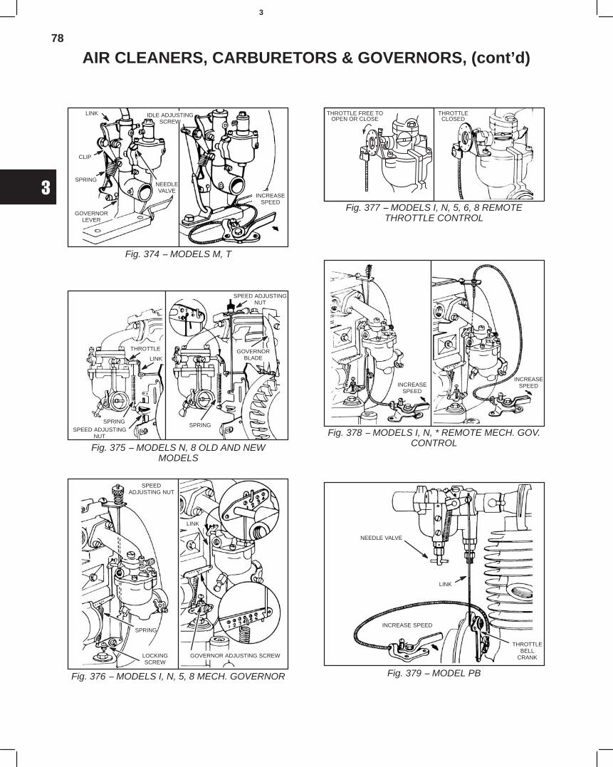
78
3
AIR CLEANERS, CARBURETORS & GOVERNORS, (cont’d)
Fig. 374 − MODELS M, T
LINK
CLIP
NEEDLEVALVE
SPRING
GOVERNORLEVER
INCREASESPEED
IDLE ADJUSTINGSCREW
Fig. 375 − MODELS N, 8 OLD AND NEWMODELS
THROTTLE
LINK
SPRINGSPEED ADJUSTING
NUT
SPEED ADJUSTINGNUT
GOVERNORBLADE
SPRING
Fig. 376 − MODELS I, N, 5, 8 MECH. GOVERNOR
SPEEDADJUSTING NUT
LOCKINGSCREW
SPRING
LINK
GOVERNOR ADJUSTING SCREW
Fig. 377 − MODELS I, N, 5, 6, 8 REMOTETHROTTLE CONTROL
THROTTLE FREE TOOPEN OR CLOSE
THROTTLECLOSED
Fig. 378 − MODELS I, N, * REMOTE MECH. GOV.CONTROL
INCREASESPEED
INCREASESPEED
Fig. 379 − MODEL PB
NEEDLE VALVE
LINK
INCREASE SPEED
THROTTLEBELL
CRANK
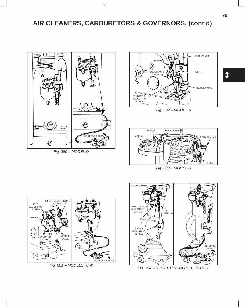
79
3
AIR CLEANERS, CARBURETORS & GOVERNORS, (cont’d)
Fig. 380 − MODEL Q
INCREASE SPEED
Fig. 381 − MODELS R, W
THROTTLE ADJUSTINGSCREWIDLE
ADJUSTINGSCREW
SPRING
CLIPGOVERNOR
LEVERNEEDLEVALVE
INCREASE SPEED
Fig. 382 − MODEL S
SPRING CLIP
LINK
NEEDLE VALVE
SPRING
GOVERNORLEVER
THROTTLEADJUSTING
SCREW
Fig. 383 − MODEL U
GASKET
WASHER FUEL OUTLET
CARBURETOR
FUELAIR
AIR BLEED
Fig. 384 − MODEL U REMOTE CONTROL
NEEDLE VALVELINK
THROTTLEADJUSTING
SCREW
FUELAIR
SPEEDADJUSTING
SCREW
SPRING
INCREASESPEED
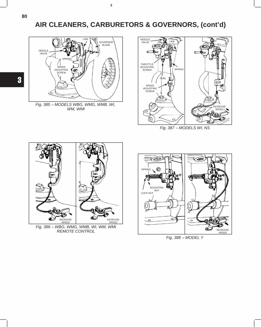
80
3
AIR CLEANERS, CARBURETORS & GOVERNORS, (cont’d)
Fig. 385 − MODELS WBG, WMG, WMB, WI, WM, WMI
NEEDLEVALVE
GOVERNORBLADE
LINK
SPRING
SPEEDADJUSTING
SCREW
Fig. 386 − WBG, WMG, WMB, WI, WM, WMIREMOTE CONTROL
INCREASESPEED
INCREASESPEED
Fig. 387 − MODELS WI, NS
NEEDLEVALVE LINK
SPRING
THROTTLEADJUSTING
SCREW
FUEL
SPEEDADJUSTING
SCREW
INCREASESPEED
Fig. 388 − MODEL Y
SPRING
ADJUSTINGNUT
LOCK NUT
INCREASESPEED
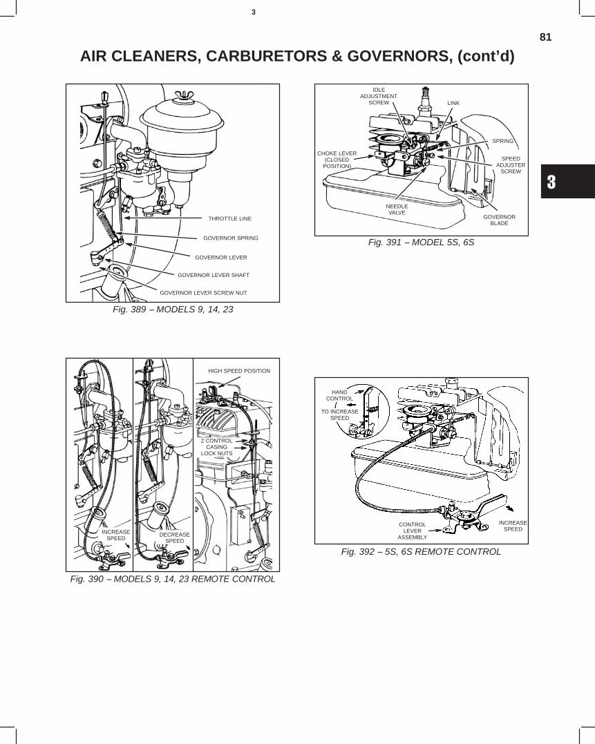
81
3
AIR CLEANERS, CARBURETORS & GOVERNORS, (cont’d)
Fig. 389 − MODELS 9, 14, 23
THROTTLE LINE
GOVERNOR SPRING
GOVERNOR LEVER
GOVERNOR LEVER SHAFT
GOVERNOR LEVER SCREW NUT
Fig. 390 − MODELS 9, 14, 23 REMOTE CONTROL
INCREASESPEED
DECREASESPEED
HIGH SPEED POSITION
2 CONTROLCASING
LOCK NUTS
Fig. 391 − MODEL 5S, 6S
IDLEADJUSTMENT
SCREW
SPRING
SPEEDADJUSTER
SCREW
GOVERNORBLADE
NEEDLEVALVE
CHOKE LEVER(CLOSED
POSITION)
LINK
Fig. 392 − 5S, 6S REMOTE CONTROL
HANDCONTROL
TO INCREASESPEED
INCREASESPEED
CONTROLLEVER
ASSEMBLY
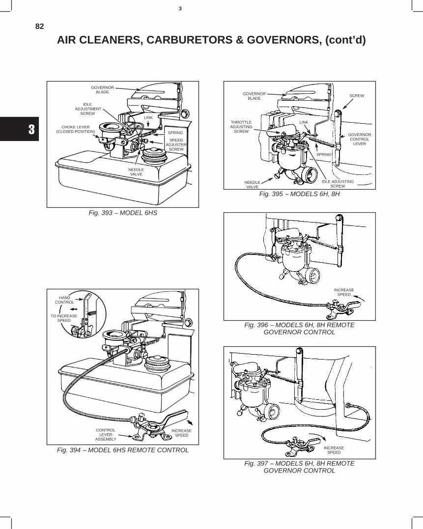
82
3
AIR CLEANERS, CARBURETORS & GOVERNORS, (cont’d)
Fig. 393 − MODEL 6HS
GOVERNORBLADE
IDLE ADJUSTMENT
SCREW
CHOKE LEVER(CLOSED POSITION)
LINK
SPRING
SPEEDADJUSTER
SCREW
NEEDLEVALVE
Fig. 394 − MODEL 6HS REMOTE CONTROL
HANDCONTROL
TO INCREASESPEED
INCREASESPEED
CONTROLLEVER
ASSEMBLY
Fig. 395 − MODELS 6H, 8H
GOVERNORBLADE
THROTTLEADJUSTING
SCREW
SCREW
GOVERNORCONTROL
LEVER
SPRING
LINK
NEEDLEVALVE
IDLE ADJUSTINGSCREW
Fig. 396 − MODELS 6H, 8H REMOTEGOVERNOR CONTROL
INCREASESPEED
Fig. 397 − MODELS 6H, 8H REMOTEGOVERNOR CONTROL
INCREASESPEED
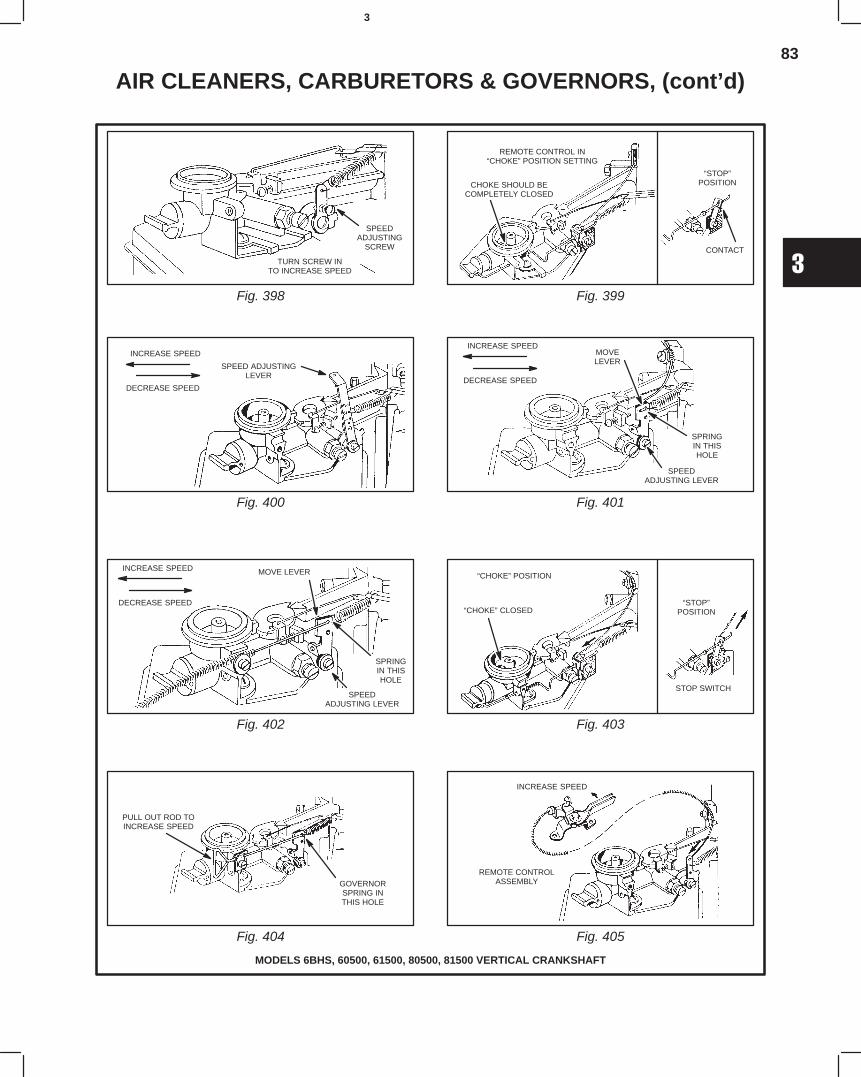
83
3
AIR CLEANERS, CARBURETORS & GOVERNORS, (cont’d)
Fig. 398 Fig. 399
MODELS 6BHS, 60500, 61500, 80500, 81500 VERTICAL CRANKSHAFT
Fig. 400 Fig. 401
Fig. 402 Fig. 403
Fig. 404 Fig. 405
SPEEDADJUSTING
SCREW
TURN SCREW INTO INCREASE SPEED
REMOTE CONTROL IN“CHOKE” POSITION SETTING
CHOKE SHOULD BECOMPLETELY CLOSED
“STOP”POSITION
CONTACT
INCREASE SPEED
DECREASE SPEED
SPEED ADJUSTINGLEVER
INCREASE SPEED
DECREASE SPEED
MOVELEVER
SPRINGIN THISHOLE
SPEEDADJUSTING LEVER
INCREASE SPEED
DECREASE SPEED
MOVE LEVER
SPRINGIN THISHOLE
SPEEDADJUSTING LEVER
“CHOKE” POSITION
“CHOKE” CLOSED“STOP”
POSITION
STOP SWITCH
PULL OUT ROD TOINCREASE SPEED
GOVERNORSPRING INTHIS HOLE
INCREASE SPEED
REMOTE CONTROLASSEMBLY
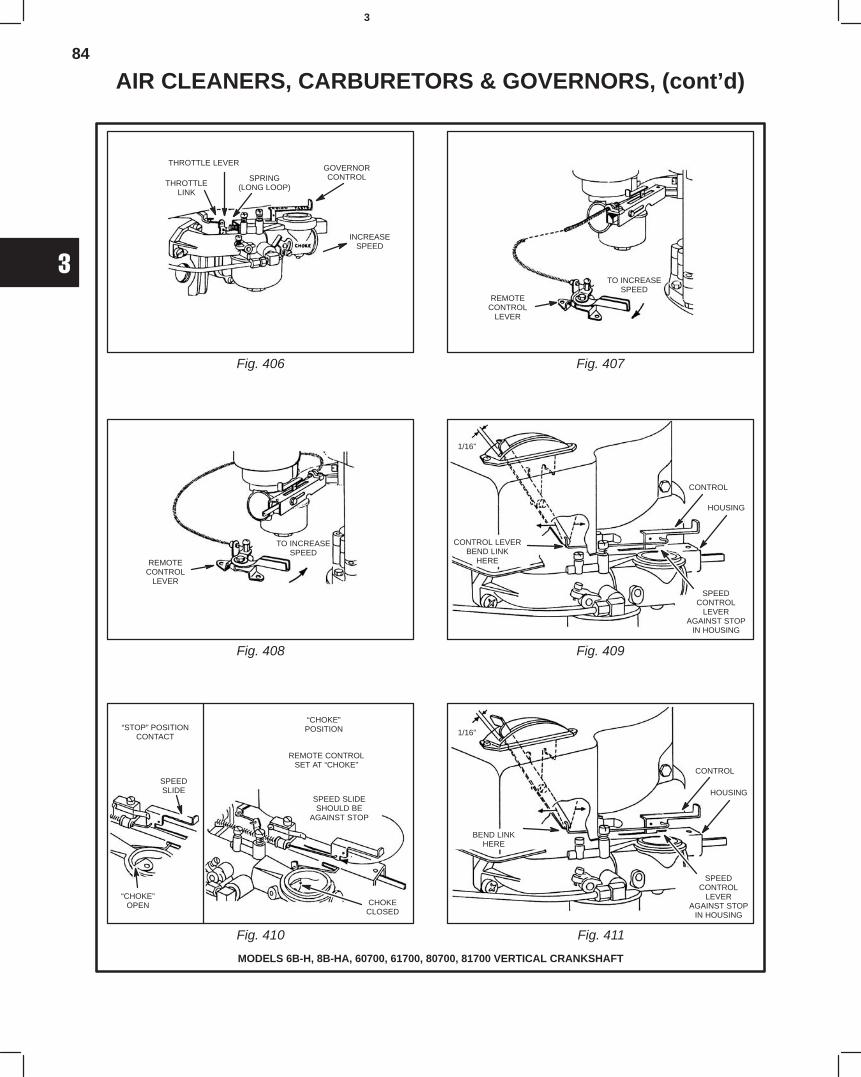
84
3
AIR CLEANERS, CARBURETORS & GOVERNORS, (cont’d)
Fig. 406 Fig. 407
Fig. 408 Fig. 409
MODELS 6B-H, 8B-HA, 60700, 61700, 80700, 81700 VERTICAL CRANKSHAFT
Fig. 410 Fig. 411
GOVERNORCONTROLSPRING
(LONG LOOP)
THROTTLE LEVER
THROTTLELINK
REMOTECONTROL
LEVER
TO INCREASESPEED
REMOTECONTROL
LEVER
TO INCREASESPEED
1/16”
CONTROL LEVERBEND LINK
HERE
CONTROL
HOUSING
SPEEDCONTROL
LEVERAGAINST STOP
IN HOUSING
“STOP” POSITIONCONTACT
SPEEDSLIDE
“CHOKE”OPEN
“CHOKE”POSITION
REMOTE CONTROLSET AT “CHOKE”
SPEED SLIDESHOULD BE
AGAINST STOP
CHOKECLOSED
1/16”
HOUSING
SPEEDCONTROL
LEVERAGAINST STOP
IN HOUSING
CONTROL
BEND LINKHERE
INCREASESPEED
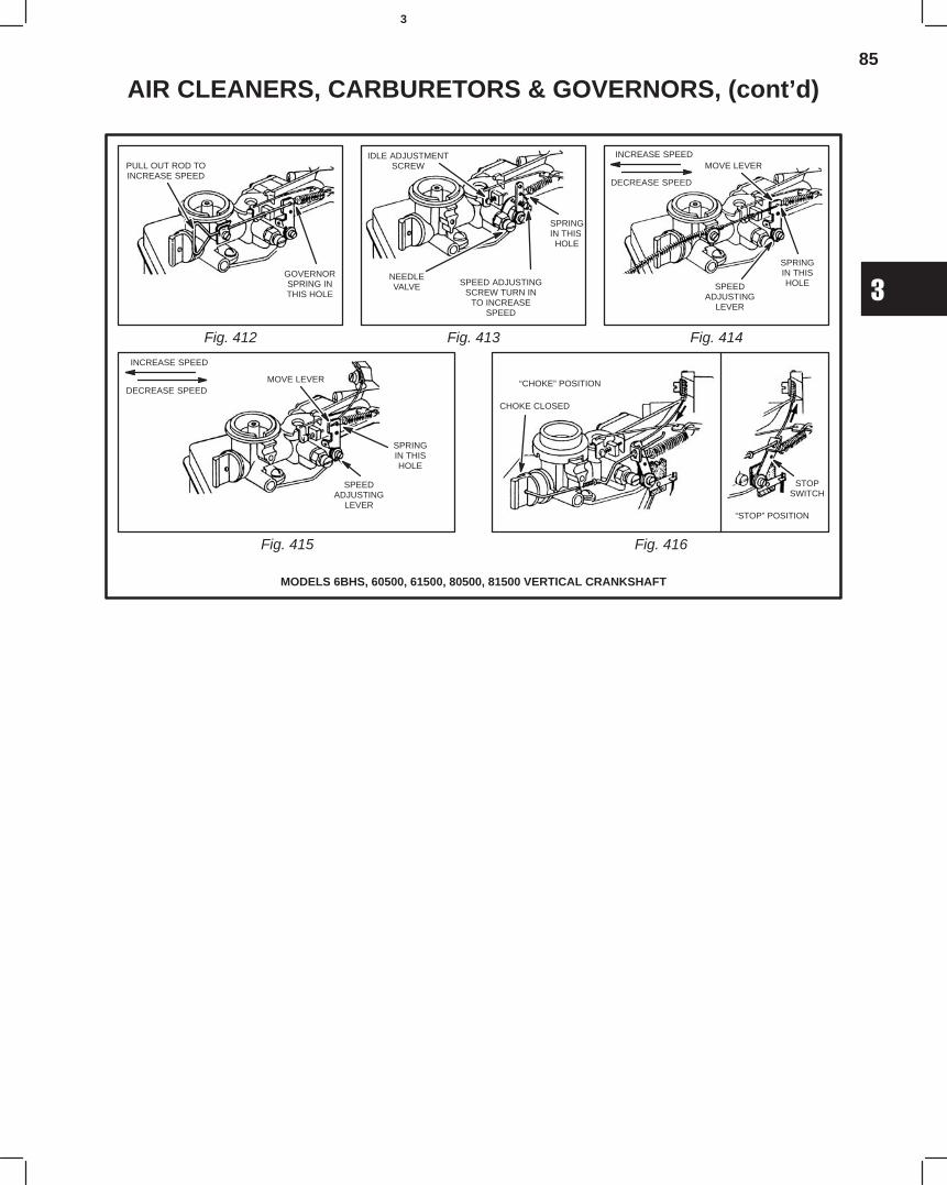
85
3
AIR CLEANERS, CARBURETORS & GOVERNORS, (cont’d)
Fig. 412
MODELS 6BHS, 60500, 61500, 80500, 81500 VERTICAL CRANKSHAFT
Fig. 413 Fig. 414
Fig. 415 Fig. 416
PULL OUT ROD TOINCREASE SPEED
GOVERNORSPRING INTHIS HOLE
IDLE ADJUSTMENTSCREW
NEEDLEVALVE
SPRINGIN THIS
HOLE
SPEED ADJUSTINGSCREW TURN IN
TO INCREASESPEED
MOVE LEVER
SPRINGIN THISHOLESPEED
ADJUSTINGLEVER
MOVE LEVER
SPRINGIN THISHOLE
SPEEDADJUSTING
LEVER
“CHOKE” POSITION
CHOKE CLOSED
STOPSWITCH
“STOP” POSITION
INCREASE SPEED
DECREASE SPEED
INCREASE SPEED
DECREASE SPEED
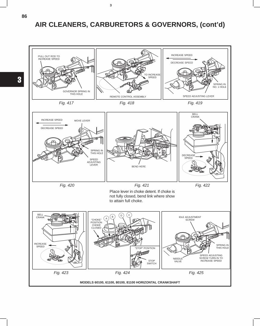
86
3
AIR CLEANERS, CARBURETORS & GOVERNORS, (cont’d)
Fig. 417 Fig. 418 Fig. 419
Fig. 420 Fig. 421 Fig. 422
Fig. 423 Fig. 424 Fig. 425
MODELS 60100, 61100, 80100, 81100 HORIZONTAL CRANKSHAFT
Place lever in choke detent. If choke isnot fully closed, bend link where showto attain full choke.
PULL OUT ROD TOINCREASE SPEED
GOVERNOR SPRING INTHIS HOLE
REMOTE CONTROL ASSEMBLY
TO INCREASESPEED
SPRING INNO. 1 HOLE
SPEED ADJUSTING LEVER
INCREASE SPEED
DECREASE SPEED
SPRING INTHIS HOLE
INCREASE SPEED
DECREASE SPEED
SPEEDADJUSTING
LEVER
MOVE LEVER
BEND HERE
DECREASESPEED
BELLCRANK
INCREASESPEED
BELLCRANK
“CHOKE”POSITION
CHOKECLOSED
AB
CDIDLE ADJUSTMENT
SCREW
NEEDLEVALVE
SPEED ADJUSTINGSCREW TURN IN TOINCREASE SPEED
SPRING INTHIS HOLE“STOP” POSITION
STOPSWITCH
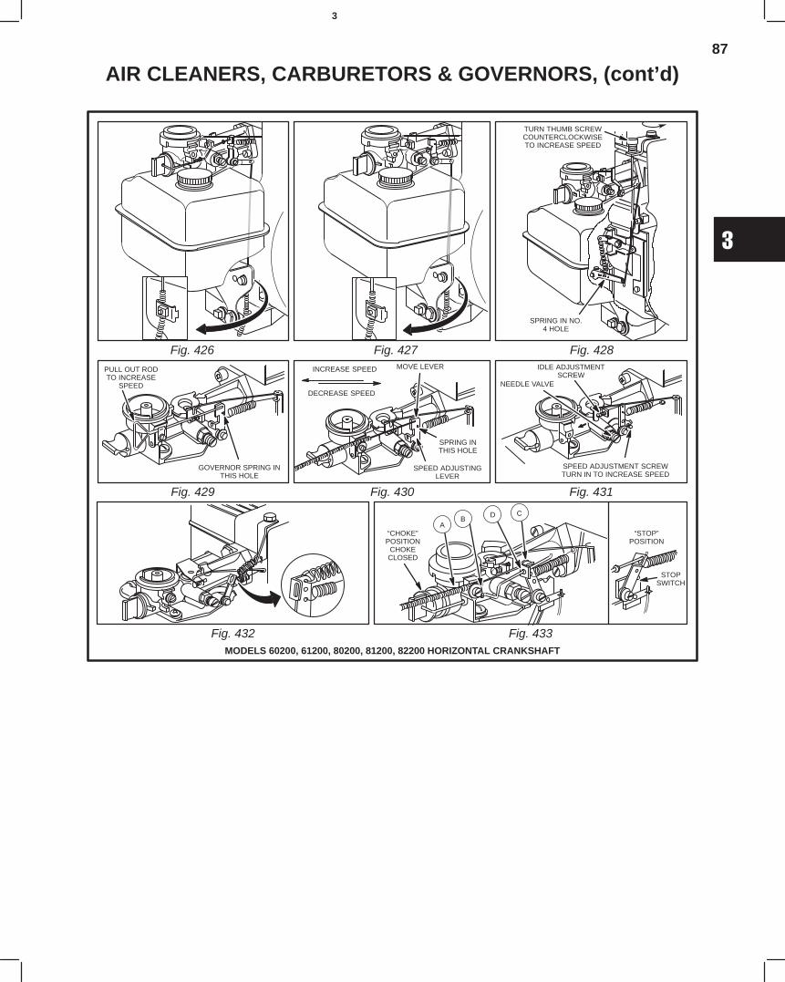
87
3
AIR CLEANERS, CARBURETORS & GOVERNORS, (cont’d)
Fig. 426 Fig. 427 Fig. 428
Fig. 429 Fig. 430 Fig. 431
Fig. 432MODELS 60200, 61200, 80200, 81200, 82200 HORIZONTAL CRANKSHAFT
Fig. 433
TURN THUMB SCREWCOUNTERCLOCKWISETO INCREASE SPEED
SPRING IN NO.4 HOLE
PULL OUT RODTO INCREASE
SPEED
GOVERNOR SPRING INTHIS HOLE
SPRING INTHIS HOLE
INCREASE SPEED
DECREASE SPEED
SPEED ADJUSTINGLEVER
MOVE LEVER IDLE ADJUSTMENTSCREW
NEEDLE VALVE
SPEED ADJUSTMENT SCREWTURN IN TO INCREASE SPEED
“STOP”POSITION
STOPSWITCH
“CHOKE”POSITION
CHOKECLOSED
AB
CD
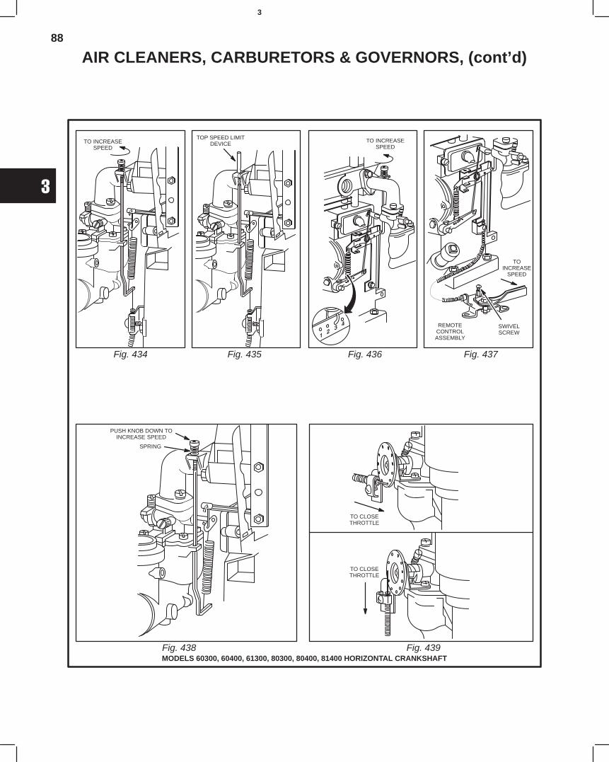
88
3
AIR CLEANERS, CARBURETORS & GOVERNORS, (cont’d)
Fig. 434 Fig. 435 Fig. 436 Fig. 437
Fig. 438MODELS 60300, 60400, 61300, 80300, 80400, 81400 HORIZONTAL CRANKSHAFT
Fig. 439
TO INCREASESPEED
TOP SPEED LIMITDEVICE TO INCREASE
SPEED
TOINCREASE
SPEED
SWIVELSCREW
REMOTECONTROLASSEMBLY
PUSH KNOB DOWN TOINCREASE SPEED
TO CLOSETHROTTLE
TO CLOSETHROTTLE
SPRING
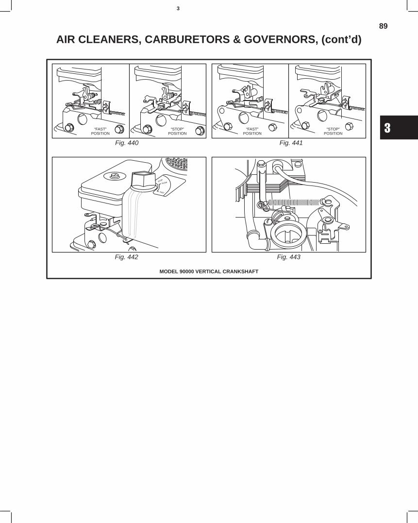
89
3
AIR CLEANERS, CARBURETORS & GOVERNORS, (cont’d)
Fig. 440 Fig. 441
Fig. 442 Fig. 443
MODEL 90000 VERTICAL CRANKSHAFT
“FAST”POSITION
“STOP”POSITION
“FAST”POSITION
“STOP”POSITION
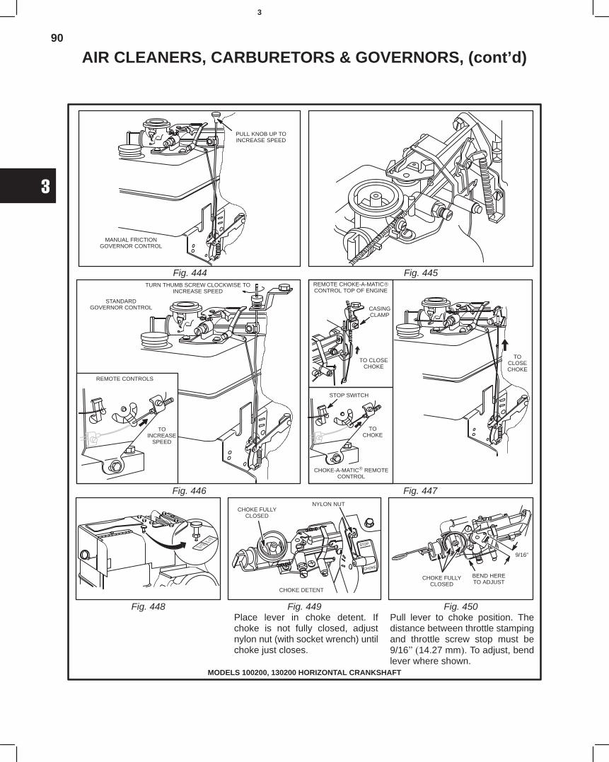
90
3
AIR CLEANERS, CARBURETORS & GOVERNORS, (cont’d)
Fig. 444
MODELS 100200, 130200 HORIZONTAL CRANKSHAFT
Fig. 445
Fig. 446 Fig. 447
Fig. 448 Fig. 449 Fig. 450Place lever in choke detent. Ifchoke is not fully closed, adjustnylon nut (with socket wrench) untilchoke just closes.
Pull lever to choke position. Thedistance between throttle stampingand throttle screw stop must be9/16" (14.27 mm). To adjust, bendlever where shown.
PULL KNOB UP TOINCREASE SPEED
MANUAL FRICTIONGOVERNOR CONTROL
TURN THUMB SCREW CLOCKWISE TOINCREASE SPEED
STANDARDGOVERNOR CONTROL
REMOTE CHOKE-A-MATICCONTROL TOP OF ENGINE
STOP SWITCH
TOCHOKE
CASINGCLAMP
TO CLOSECHOKE
TOCLOSECHOKE
CHOKE-A-MATIC REMOTECONTROL
CHOKE FULLYCLOSED
NYLON NUT
CHOKE DETENT
CHOKE FULLYCLOSED
BEND HERETO ADJUST
9/16”
REMOTE CONTROLS
TOINCREASE
SPEED
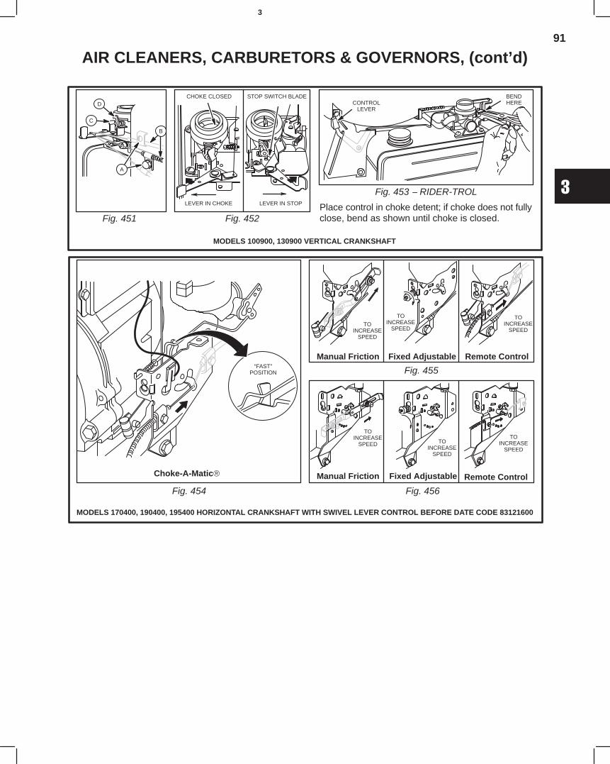
91
3
AIR CLEANERS, CARBURETORS & GOVERNORS, (cont’d)
Fig. 451 Fig. 452Place control in choke detent; if choke does not fullyclose, bend as shown until choke is closed.
Fig. 453 − RIDER-TROL
MODELS 100900, 130900 VERTICAL CRANKSHAFT
A
B
C
DCHOKE CLOSED
LEVER IN CHOKE LEVER IN STOP
STOP SWITCH BLADECONTROL
LEVER
BENDHERE
MODELS 170400, 190400, 195400 HORIZONTAL CRANKSHAFT WITH SWIVEL LEVER CONTROL BEFORE DATE CODE 83121600
Fig. 454
Fig. 455
Fig. 456
“FAST”POSITION
TOINCREASE
SPEED
TOINCREASE
SPEED
TOINCREASE
SPEED
TOINCREASE
SPEED TOINCREASE
SPEED
TOINCREASE
SPEED
Choke-A-Matic
Manual Friction
Manual Friction
Fixed Adjustable
Fixed Adjustable
Remote Control
Remote Control
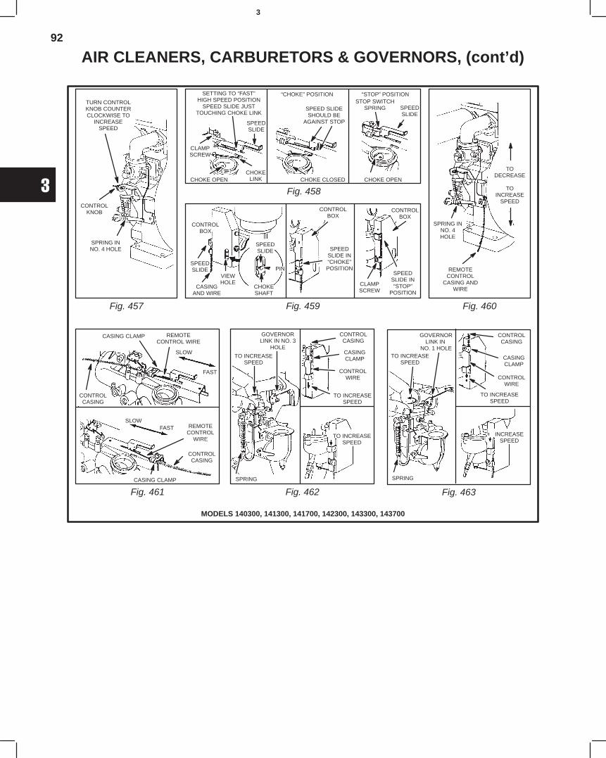
92
3
AIR CLEANERS, CARBURETORS & GOVERNORS, (cont’d)
MODELS 140300, 141300, 141700, 142300, 143300, 143700
Fig. 457
Fig. 458
Fig. 459 Fig. 460
Fig. 461 Fig. 462 Fig. 463
TURN CONTROLKNOB COUNTERCLOCKWISE TO
INCREASESPEED
CONTROLKNOB
SPRING INNO. 4 HOLE
SETTING TO “FAST”HIGH SPEED POSITION
SPEED SLIDE JUSTTOUCHING CHOKE LINK
SPEEDSLIDE
CLAMPSCREW
CHOKELINKCHOKE OPEN
“CHOKE” POSITION
SPEED SLIDESHOULD BE
AGAINST STOP
CHOKE CLOSED
“STOP” POSITIONSTOP SWITCH
SPRING SPEEDSLIDE
CHOKE OPEN
CONTROLBOX
SPEEDSLIDE
CASINGAND WIRE
VIEWHOLE
SPEEDSLIDE
PIN
CHOKESHAFT
CONTROLBOX
SPEEDSLIDE IN“CHOKE”POSITION
CONTROLBOX
CLAMPSCREW
SPEEDSLIDE IN“STOP”
POSITION
TODECREASE
TOINCREASE
SPEED
SPRING INNO. 4HOLE
REMOTECONTROL
CASING ANDWIRE
CASING CLAMP REMOTECONTROL WIRE
SLOW
FAST
CONTROLCASING
FASTSLOW
REMOTECONTROL
WIRE
CONTROLCASING
CASING CLAMP
GOVERNORLINK IN NO. 3
HOLE
CONTROLCASING
CASINGCLAMP
CONTROLWIRE
TO INCREASESPEED
SPRING
TO INCREASESPEED
GOVERNORLINK IN
NO. 1 HOLETO INCREASE
SPEED
SPRING
CONTROLCASING
CASINGCLAMP
CONTROLWIRE
TO INCREASESPEED
INCREASESPEED
TO INCREASESPEED
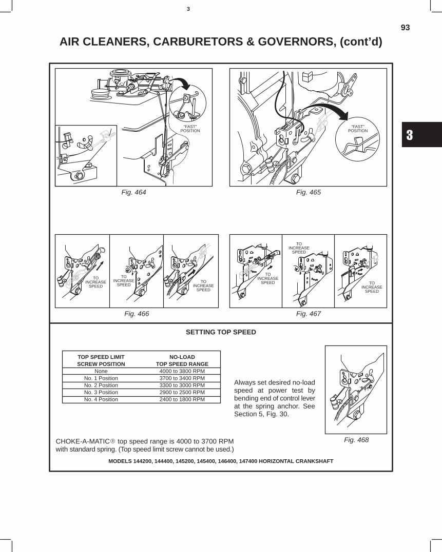
93
3
AIR CLEANERS, CARBURETORS & GOVERNORS, (cont’d)
Fig. 464
MODELS 144200, 144400, 145200, 145400, 146400, 147400 HORIZONTAL CRANKSHAFT
Fig. 465
Fig. 466
CHOKE-A-MATIC top speed range is 4000 to 3700 RPMwith standard spring. (Top speed limit screw cannot be used.)
Fig. 467
Fig. 468
SETTING TOP SPEED
TOP SPEED LIMIT NO-LOADSCREW POSITION TOP SPEED RANGE
None 4000 to 3800 RPMNo. 1 Position 3700 to 3400 RPMNo. 2 Position 3300 to 3000 RPMNo. 3 Position 2900 to 2500 RPMNo. 4 Position 2400 to 1800 RPM
Always set desired no-loadspeed at power test bybending end of control leverat the spring anchor. SeeSection 5, Fig. 30.
“FAST”POSITION
“FAST”POSITION
TOINCREASE
SPEED
TOINCREASE
SPEEDTO
INCREASESPEED
TOINCREASE
SPEED
TOINCREASE
SPEED
TOINCREASE
SPEED
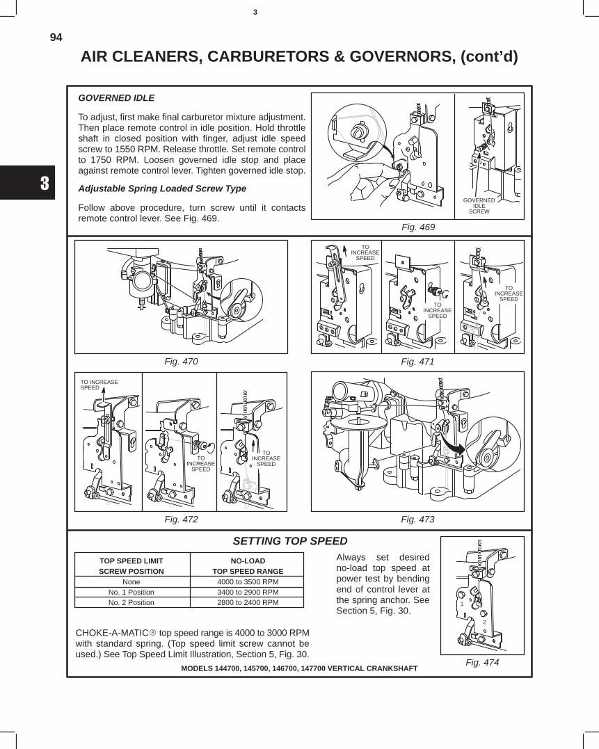
94
3
AIR CLEANERS, CARBURETORS & GOVERNORS, (cont’d)
TOP SPEED LIMIT NO-LOADSCREW POSITION TOP SPEED RANGE
None 4000 to 3500 RPMNo. 1 Position 3400 to 2900 RPMNo. 2 Position 2800 to 2400 RPM
MODELS 144700, 145700, 146700, 147700 VERTICAL CRANKSHAFT
CHOKE-A-MATIC top speed range is 4000 to 3000 RPMwith standard spring. (Top speed limit screw cannot beused.) See Top Speed Limit Illustration, Section 5, Fig. 30.
SETTING TOP SPEEDAlways set desiredno-load top speed atpower test by bendingend of control lever atthe spring anchor. SeeSection 5, Fig. 30.
GOVERNED IDLE
To adjust, first make final carburetor mixture adjustment.Then place remote control in idle position. Hold throttleshaft in closed position with finger, adjust idle speedscrew to 1550 RPM. Release throttle. Set remote controlto 1750 RPM. Loosen governed idle stop and placeagainst remote control lever. Tighten governed idle stop.
Adjustable Spring Loaded Screw Type
Follow above procedure, turn screw until it contactsremote control lever. See Fig. 469.
Fig. 469
Fig. 470 Fig. 471
Fig. 472 Fig. 473
Fig. 474
GOVERNEDIDLE
SCREW
TOINCREASE
SPEED
TOINCREASE
SPEED
TOINCREASE
SPEED
TOINCREASE
SPEED
TOINCREASE
SPEED
1
2
TO INCREASESPEED
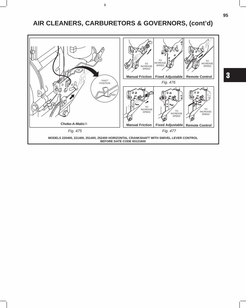
95
3
AIR CLEANERS, CARBURETORS & GOVERNORS, (cont’d)
MODELS 220400, 221400, 251400, 252400 HORIZONTAL CRANKSHAFT WITH SWIVEL LEVER CONTROLBEFORE DATE CODE 83121600
Fig. 475
Fig. 476
Fig. 477
“FAST”POSITION
TOINCREASE
SPEED
TOINCREASE
SPEED
TOINCREASE
SPEED
TOINCREASE
SPEED TOINCREASE
SPEED
TOINCREASE
SPEED
Choke-A-Matic
Manual Friction
Manual Friction
Fixed Adjustable
Fixed Adjustable
Remote Control
Remote Control
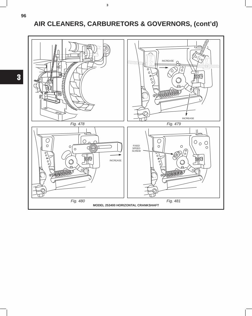
96
3
AIR CLEANERS, CARBURETORS & GOVERNORS, (cont’d)
Fig. 478 Fig. 479
MODEL 253400 HORIZONTAL CRANKSHAFTFig. 480
INCREASE
INCREASE
INCREASE
FIXEDSPEEDSCREW
Fig. 481
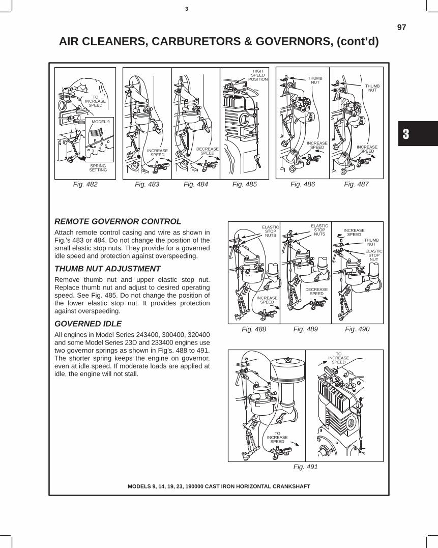
97
3
AIR CLEANERS, CARBURETORS & GOVERNORS, (cont’d)
ELASTICSTOPNUTS
MODELS 9, 14, 19, 23, 190000 CAST IRON HORIZONTAL CRANKSHAFT
REMOTE GOVERNOR CONTROLAttach remote control casing and wire as shown inFig.’s 483 or 484. Do not change the position of thesmall elastic stop nuts. They provide for a governedidle speed and protection against overspeeding.
THUMB NUT ADJUSTMENTRemove thumb nut and upper elastic stop nut.Replace thumb nut and adjust to desired operatingspeed. See Fig. 485. Do not change the position ofthe lower elastic stop nut. It provides protectionagainst overspeeding.
GOVERNED IDLEAll engines in Model Series 243400, 300400, 320400and some Model Series 23D and 233400 engines usetwo governor springs as shown in Fig’s. 488 to 491.The shorter spring keeps the engine on governor,even at idle speed. If moderate loads are applied atidle, the engine will not stall.
Fig. 482 Fig. 483 Fig. 484 Fig. 485 Fig. 486 Fig. 487
Fig. 488 Fig. 489 Fig. 490
Fig. 491
SPRINGSETTING
MODEL 9
34 5
TOINCREASE
SPEED
INCREASESPEED
DECREASESPEED
HIGHSPEED
POSITION
INCREASESPEED
THUMBNUT
INCREASESPEED
THUMBNUT
ELASTICSTOPNUTS
INCREASESPEED
DECREASESPEED
ELASTICSTOPNUT
INCREASESPEED
THUMBNUT
TOINCREASE
SPEED
TOINCREASE
SPEED
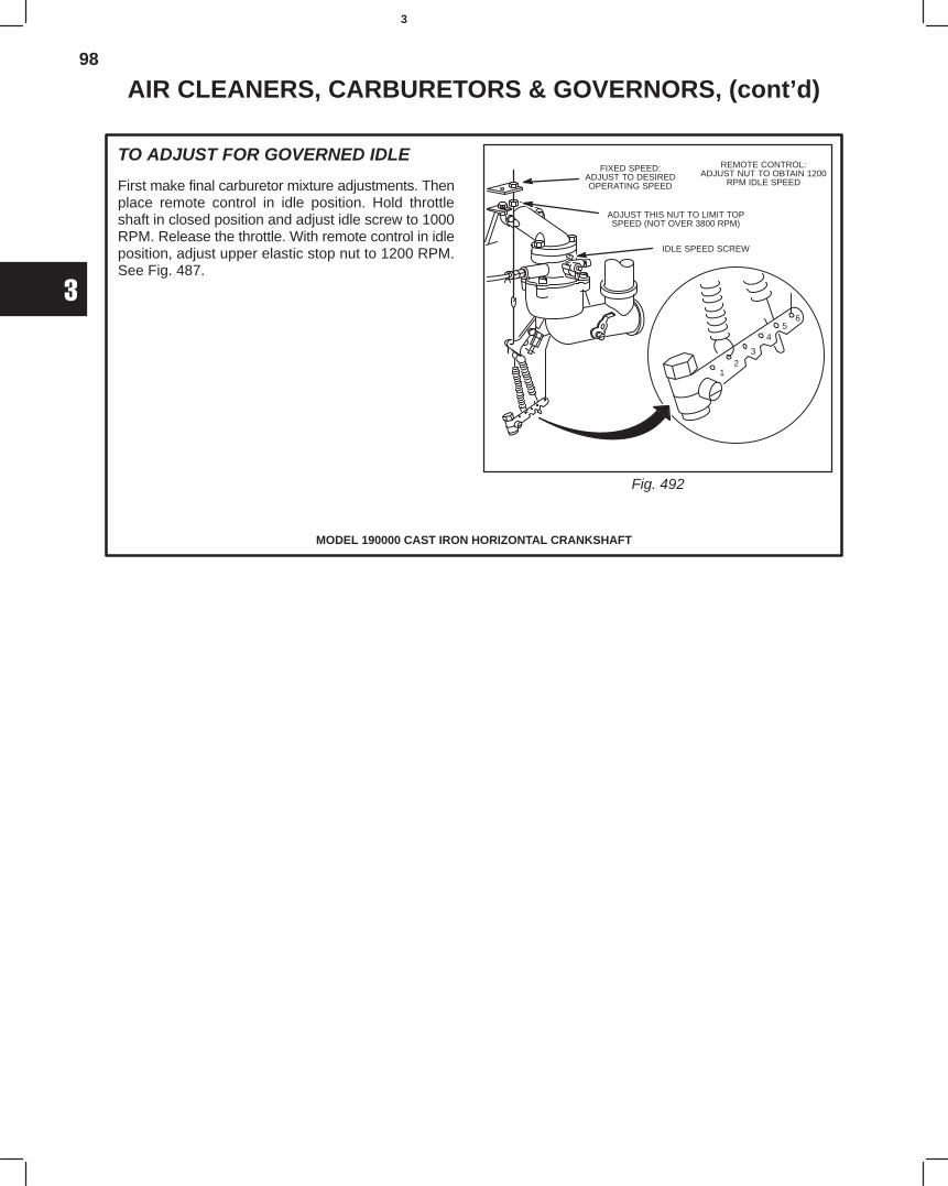
98
3
AIR CLEANERS, CARBURETORS & GOVERNORS, (cont’d)
MODEL 190000 CAST IRON HORIZONTAL CRANKSHAFT
TO ADJUST FOR GOVERNED IDLE
First make final carburetor mixture adjustments. Thenplace remote control in idle position. Hold throttleshaft in closed position and adjust idle screw to 1000RPM. Release the throttle. With remote control in idleposition, adjust upper elastic stop nut to 1200 RPM.See Fig. 487.
Fig. 492
FIXED SPEED:ADJUST TO DESIREDOPERATING SPEED
ADJUST THIS NUT TO LIMIT TOPSPEED (NOT OVER 3800 RPM)
REMOTE CONTROL:ADJUST NUT TO OBTAIN 1200
RPM IDLE SPEED
IDLE SPEED SCREW
12
3
45
6
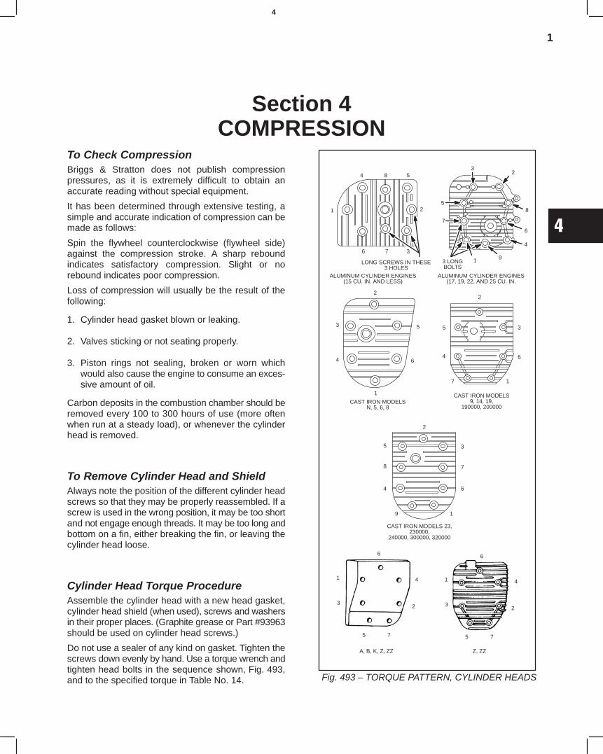
1
4
Section 4COMPRESSION
To Check CompressionBriggs & Stratton does not publish compressionpressures, as it is extremely difficult to obtain anaccurate reading without special equipment.
It has been determined through extensive testing, asimple and accurate indication of compression can bemade as follows:
Spin the flywheel counterclockwise (flywheel side)against the compression stroke. A sharp reboundindicates satisfactory compression. Slight or norebound indicates poor compression.
Loss of compression will usually be the result of thefollowing:
1. Cylinder head gasket blown or leaking.
2. Valves sticking or not seating properly.
3. Piston rings not sealing, broken or worn whichwould also cause the engine to consume an exces-sive amount of oil.
Carbon deposits in the combustion chamber should beremoved every 100 to 300 hours of use (more oftenwhen run at a steady load), or whenever the cylinderhead is removed.
To Remove Cylinder Head and ShieldAlways note the position of the different cylinder headscrews so that they may be properly reassembled. If ascrew is used in the wrong position, it may be too shortand not engage enough threads. It may be too long andbottom on a fin, either breaking the fin, or leaving thecylinder head loose.
Cylinder Head Torque ProcedureAssemble the cylinder head with a new head gasket,cylinder head shield (when used), screws and washersin their proper places. (Graphite grease or Part #93963should be used on cylinder head screws.)
Do not use a sealer of any kind on gasket. Tighten thescrews down evenly by hand. Use a torque wrench andtighten head bolts in the sequence shown, Fig. 493,and to the specified torque in Table No. 14. Fig. 493 – TORQUE PATTERN, CYLINDER HEADS
CAST IRON MODELS9, 14, 19,
190000, 200000CAST IRON MODELS
N, 5, 6, 8
1
4
3
2
5
6
2
5
4
7 1
6
3
2
3
7
6
19
4
8
5
CAST IRON MODELS 23,230000,
240000, 300000, 320000
ALUMINUM CYLINDER ENGINES(15 CU. IN. AND LESS)
32
8
6
4
91
7
5
ALUMINUM CYLINDER ENGINES(17, 19, 22, AND 25 CU. IN.
4 8 5
2
376
1
3 LONGBOLTS
LONG SCREWS IN THESE3 HOLES
6
4
2
75
3
1
6
4
2
75
3
1
A, B, K, Z, ZZ Z, ZZ
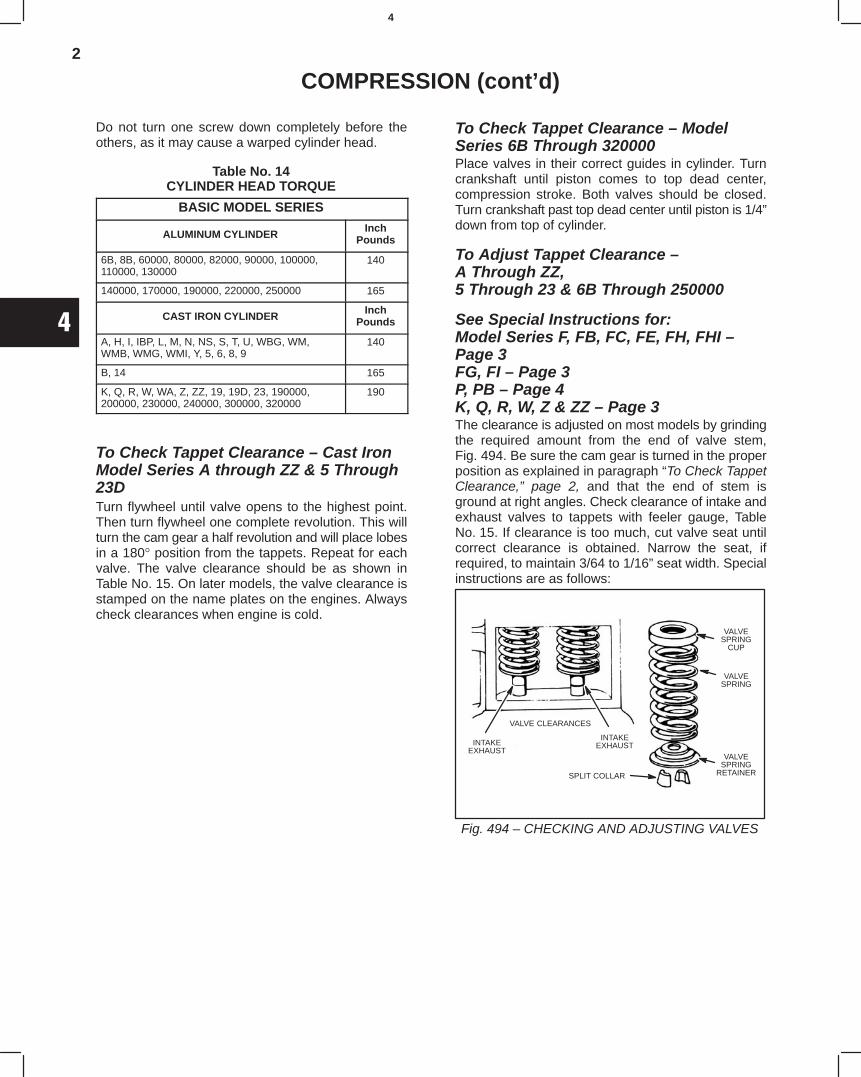
2
4
COMPRESSION (cont’d)
Do not turn one screw down completely before theothers, as it may cause a warped cylinder head.
Table No. 14CYLINDER HEAD TORQUE
BASIC MODEL SERIES
ALUMINUM CYLINDERInch
Pounds
6B, 8B, 60000, 80000, 82000, 90000, 100000,110000, 130000
140
140000, 170000, 190000, 220000, 250000 165
CAST IRON CYLINDERInch
Pounds
A, H, I, IBP, L, M, N, NS, S, T, U, WBG, WM,WMB, WMG, WMI, Y, 5, 6, 8, 9
140
B, 14 165
K, Q, R, W, WA, Z, ZZ, 19, 19D, 23, 190000,200000, 230000, 240000, 300000, 320000
190
To Check Tappet Clearance – Cast IronModel Series A through ZZ & 5 Through23D Turn flywheel until valve opens to the highest point.Then turn flywheel one complete revolution. This willturn the cam gear a half revolution and will place lobesin a 180° position from the tappets. Repeat for eachvalve. The valve clearance should be as shown inTable No. 15. On later models, the valve clearance isstamped on the name plates on the engines. Alwayscheck clearances when engine is cold.
To Check Tappet Clearance – ModelSeries 6B Through 320000Place valves in their correct guides in cylinder. Turncrankshaft until piston comes to top dead center,compression stroke. Both valves should be closed.Turn crankshaft past top dead center until piston is 1/4”down from top of cylinder.
To Adjust Tappet Clearance – A Through ZZ, 5 Through 23 & 6B Through 250000
See Special Instructions for:Model Series F, FB, FC, FE, FH, FHI –Page 3FG, FI – Page 3P, PB – Page 4K, Q, R, W, Z & ZZ – Page 3The clearance is adjusted on most models by grindingthe required amount from the end of valve stem,Fig. 494. Be sure the cam gear is turned in the properposition as explained in paragraph “To Check TappetClearance,” page 2, and that the end of stem isground at right angles. Check clearance of intake andexhaust valves to tappets with feeler gauge, TableNo. 15. If clearance is too much, cut valve seat untilcorrect clearance is obtained. Narrow the seat, ifrequired, to maintain 3/64 to 1/16” seat width. Specialinstructions are as follows:
Fig. 494 – CHECKING AND ADJUSTING VALVES
VALVE CLEARANCES
INTAKEEXHAUST
VALVESPRING
CUP
VALVESPRING
VALVESPRING
RETAINERSPLIT COLLAR
INTAKEEXHAUST
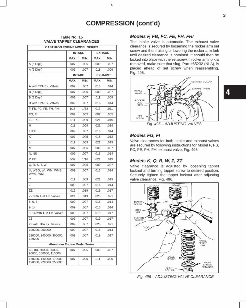
3
4
COMPRESSION (cont’d)
Table No. 15VALVE TAPPET CLEARANCESCAST IRON ENGINE MODEL SERIES
INTAKE EXHAUST
MAX. MIN. MAX. MIN.
A (5 Digit) .007 .005 .009 .007
A (6 Digit) .009 .007 .011 .009
INTAKE EXHAUST
MAX. MIN. MAX. MIN.
A with TPA Ex. Valves .009 .007 .016 .014
B (5 Digit) .007 .005 .009 .007
B (6 Digit) .009 .007 .011 .009
B with TPA Ex. Valves .009 .007 .016 .014
F, FB, FC, FE, FH, FHI 1/16 1/32 .013 .011
FG, FI .007 .005 .007 .005
FJ-1 & 2 .011 .009 .021 .019
H .011 .009 .021 .019
I, IBP .009 .007 .016 .014
K .007 .005 .015 .013
L .011 .009 .021 .019
M .007 .005 .009 .007
N, NS .009 .007 .016 .014
P, PB 3/32 1/16 .021 .019
Q, R, S, T, W .007 .005 .009 .007
U, WBG, WI, WM, WMB,WMG, WMI
.009 .007 .016 .014
Y .011 .009 .021 .019
Z .009 .007 .016 .014
ZZ .012 .019 .019 .017
ZZ with TPA Ex. Valves .021 .019 .023 .021
5, 6, 8 .009 .007 .016 .014
9, 14 .009 .007 .016 .014
9, 14 with TPA Ex. Valves .009 .007 .019 .017
23 .009 .007 .019 .017
23 with TPA Ex. Valves .009 .007 .023 .021
190000, 200000 .009 .007 .016 .014
230000, 240000, 300000,320000
.009 .007 .019 .017
Aluminum Engine Model Series
6B, 8B, 60000, 80000,90000, 100000, 110000
.007 .005 .009 .007
130000, 140000, 170000,190000, 220000, 250000
.007 .005 .011 .009
Models F, FB, FC, FE, FH, FHI The intake valve is automatic. The exhaust valveclearance is secured by loosening the rocker arm setscrew and then raising or lowering the rocker arm forkuntil desired clearance is obtained. It should then belocked into place with the set screw. If rocker arm fork isremoved, make sure that slug, Part #65232 (NLA), isplaced ahead of set screw when reassembling,Fig. 495.
Fig. 495 – ADJUSTING VALVES
INTAKEVALVE
SETSCREW
GAP
RETAINER COLLAR
EXHAUST VALVE
ROCKERARM
FORK
Models FG, FI Valve clearances for both intake and exhaust valvesare secured by following instructions for Model F, FB,FC, FE, FH, FHI exhaust valve, Fig. 495.
Models K, Q, R, W, Z, ZZ Valve clearance is adjusted by loosening tappetlocknut and turning tappet screw to desired position.Securely tighten the tappet locknut after adjustingvalve clearance, Fig. 496.
Fig. 496 – ADJUSTING VALVE CLEARANCE
EXHAUST INTAKE
GAPGAPTAPPETSCREW
LOCKNUT
FLAT ONTAPPET
VALVESPRING
CUP
VALVESPRING
SPLITCOLLAR
VALVESPRING
RETAINER
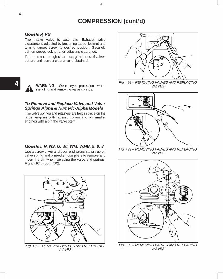
4
4
COMPRESSION (cont’d)
Models P, PB The intake valve is automatic. Exhaust valveclearance is adjusted by loosening tappet locknut andturning tappet screw to desired position. Securelytighten tappet locknut after adjusting clearance.
If there is not enough clearance, grind ends of valvessquare until correct clearance is obtained.
WARNING: Wear eye protection wheninstalling and removing valve springs.
To Remove and Replace Valve and ValveSprings Alpha & Numeric-Alpha ModelsThe valve springs and retainers are held in place on thelarger engines with tapered collars and on smallerengines with a pin the valve stem.
Models I, N, NS, U, WI, WM, WMB, 5, 6, 8Use a screw driver and open end wrench to pry up onvalve spring and a needle nose pliers to remove andinsert the pin when replacing the valve and springs,Fig’s. 497 through 502.
Fig. 497 – REMOVING VALVES AND REPLACINGVALVES
Fig. 498 – REMOVING VALVES AND REPLACINGVALVES
Fig. 499 – REMOVING VALVES AND REPLACINGVALVES
Fig. 500 – REMOVING VALVES AND REPLACINGVALVES
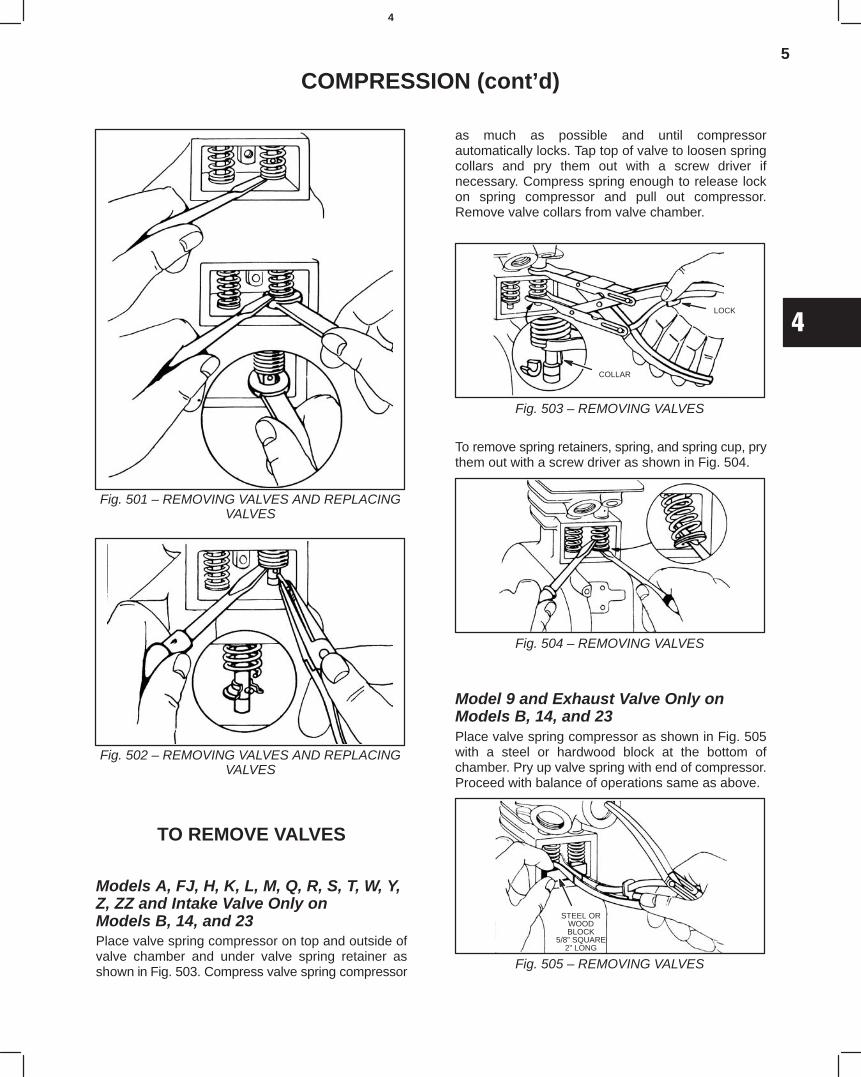
5
4
COMPRESSION (cont’d)
Fig. 501 – REMOVING VALVES AND REPLACINGVALVES
Fig. 502 – REMOVING VALVES AND REPLACINGVALVES
TO REMOVE VALVES
Models A, FJ, H, K, L, M, Q, R, S, T, W, Y,Z, ZZ and Intake Valve Only on Models B, 14, and 23Place valve spring compressor on top and outside ofvalve chamber and under valve spring retainer asshown in Fig. 503. Compress valve spring compressor
as much as possible and until compressorautomatically locks. Tap top of valve to loosen springcollars and pry them out with a screw driver ifnecessary. Compress spring enough to release lockon spring compressor and pull out compressor.Remove valve collars from valve chamber.
Fig. 503 – REMOVING VALVES
LOCK
COLLAR
To remove spring retainers, spring, and spring cup, prythem out with a screw driver as shown in Fig. 504.
Fig. 504 – REMOVING VALVES
Model 9 and Exhaust Valve Only onModels B, 14, and 23Place valve spring compressor as shown in Fig. 505with a steel or hardwood block at the bottom ofchamber. Pry up valve spring with end of compressor.Proceed with balance of operations same as above.
Fig. 505 – REMOVING VALVES
STEEL ORWOODBLOCK
5/8” SQUARE2” LONG
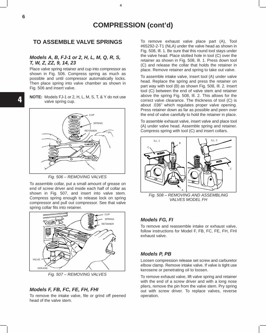
6
4
COMPRESSION (cont’d)
TO ASSEMBLE VALVE SPRINGS
Models A, B, FJ-1 or 2, H, L, M, Q, R, S,T, W, Z, ZZ, 9, 14, 23Place valve spring retainer and cup into compressor asshown in Fig. 506. Compress spring as much aspossible and until compressor automatically locks.Then place spring into valve chamber as shown inFig. 506 and insert valve.
NOTE: Models FJ-1 or 2, H, L, M, S, T, & Y do not usevalve spring cup.
Fig. 506 – REMOVING VALVES
CUP
SPRING
RETAINER
To assemble collar, put a small amount of grease onend of screw driver and inside each half of collar asshown in Fig. 507, and insert into valve stem.Compress spring enough to release lock on springcompressor and pull out compressor. See that valvespring collar fits into retainer.
Fig. 507 – REMOVING VALVES
CUP
SPRING
RETAINER
VALVE
GREASE
Models F, FB, FC, FE, FH, FHITo remove the intake valve, file or grind off peenedhead of the valve stem.
To remove exhaust valve place part (A), Tool#65292-2-T1 (NLA) under the valve head as shown inFig. 508, Ill. 1. Be sure that this round tool stays underthe valve head. Place slotted hole in tool (C) over theretainer as shown in Fig. 508, Ill. 1. Press down tool(C) and release the collar that holds the retainer inplace. Remove retainer and spring to take out valve.
To assemble intake valve, insert tool (A) under valvehead. Replace the spring and press the retainer onpart way with tool (B) as shown Fig. 508, Ill. 2. Inserttool (C) between the end of valve stem and retainerabove the spring Fig. 508, Ill. 2. This allows for thecorrect valve clearance. The thickness of tool (C) isabout .036” which regulates proper valve opening.Press retainer down as far as possible and peen overthe end of valve carefully to hold the retainer in place.
To assemble exhaust valve, insert valve and place tool(A) under valve head. Assemble spring and retainer.Compress spring with tool (C) and insert collars.
Fig. 508 – REMOVING AND ASSEMBLINGVALVES MODEL FH
ILL. 1 ILL. 2
C
B
A
C
Models FG, FITo remove and reassemble intake or exhaust valve,follow instructions for Model F, FB, FC, FE, FH, FHIexhaust valve.
Models P, PBLoosen compression release set screw and carburetorelbow clamp. Remove intake valve. If valve is tight usekerosene or penetrating oil to loosen.
To remove exhaust valve, lift valve spring and retainerwith the end of a screw driver and with a long nosepliers, remove the pin from the valve stem. Pry springout with screw driver. To replace valves, reverseoperation.
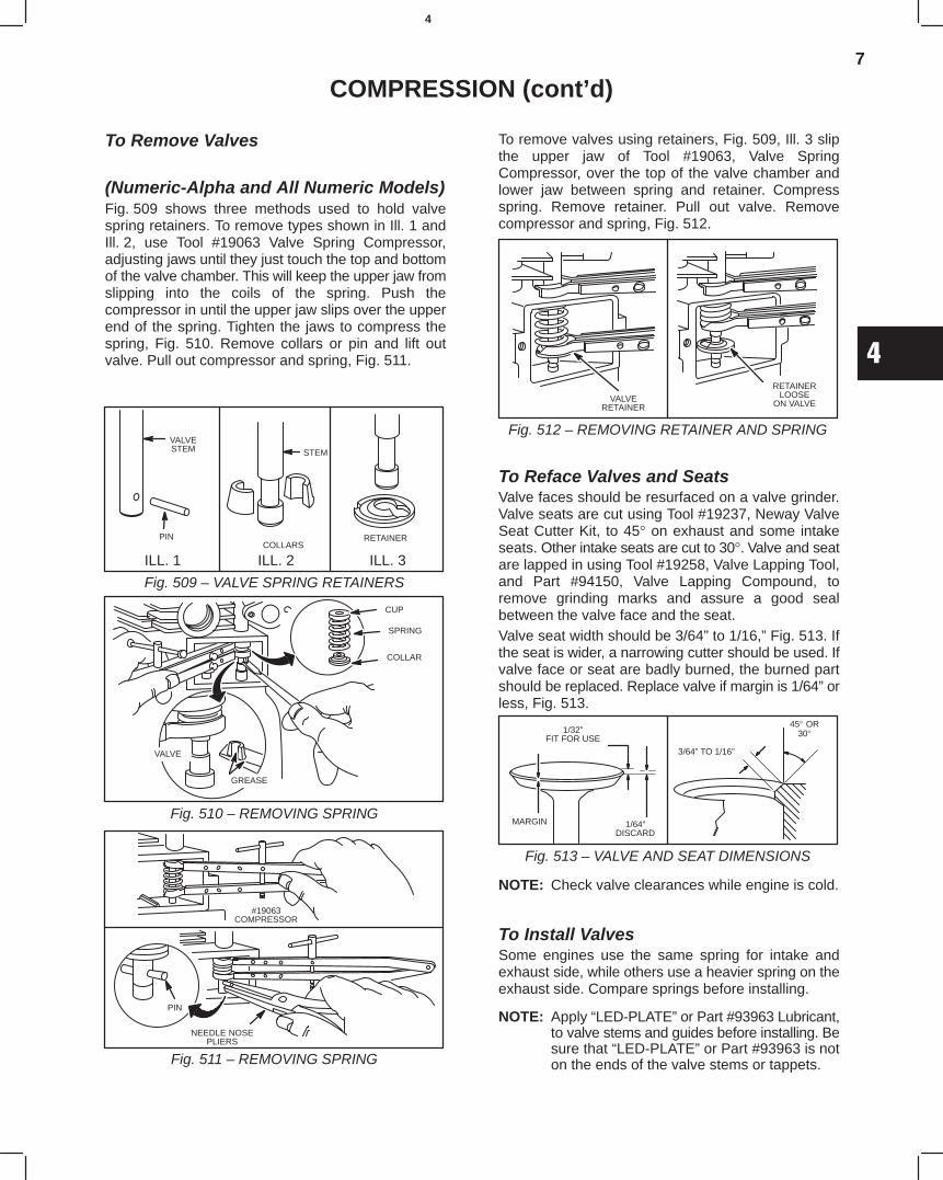
7
4
COMPRESSION (cont’d)
To Remove Valves
(Numeric-Alpha and All Numeric Models)Fig. 509 shows three methods used to hold valvespring retainers. To remove types shown in Ill. 1 andIll. 2, use Tool #19063 Valve Spring Compressor,adjusting jaws until they just touch the top and bottomof the valve chamber. This will keep the upper jaw fromslipping into the coils of the spring. Push thecompressor in until the upper jaw slips over the upperend of the spring. Tighten the jaws to compress thespring, Fig. 510. Remove collars or pin and lift outvalve. Pull out compressor and spring, Fig. 511.
Fig. 509 – VALVE SPRING RETAINERS
ILL. 1 ILL. 2 ILL. 3
PIN
VALVESTEM
COLLARS
STEM
RETAINER
Fig. 510 – REMOVING SPRING
CUP
SPRING
COLLAR
GREASE
VALVE
Fig. 511 – REMOVING SPRING
#19063COMPRESSOR
PIN
NEEDLE NOSEPLIERS
To remove valves using retainers, Fig. 509, Ill. 3 slipthe upper jaw of Tool #19063, Valve SpringCompressor, over the top of the valve chamber andlower jaw between spring and retainer. Compressspring. Remove retainer. Pull out valve. Removecompressor and spring, Fig. 512.
Fig. 512 – REMOVING RETAINER AND SPRING
VALVERETAINER
RETAINERLOOSE
ON VALVE
To Reface Valves and SeatsValve faces should be resurfaced on a valve grinder.Valve seats are cut using Tool #19237, Neway ValveSeat Cutter Kit, to 45° on exhaust and some intakeseats. Other intake seats are cut to 30°. Valve and seatare lapped in using Tool #19258, Valve Lapping Tool,and Part #94150, Valve Lapping Compound, toremove grinding marks and assure a good sealbetween the valve face and the seat.Valve seat width should be 3/64” to 1/16,” Fig. 513. Ifthe seat is wider, a narrowing cutter should be used. Ifvalve face or seat are badly burned, the burned partshould be replaced. Replace valve if margin is 1/64” orless, Fig. 513.
Fig. 513 – VALVE AND SEAT DIMENSIONS
1/32”FIT FOR USE
MARGIN 1/64”DISCARD
45° OR30°
3/64” TO 1/16”
NOTE: Check valve clearances while engine is cold.
To Install ValvesSome engines use the same spring for intake andexhaust side, while others use a heavier spring on theexhaust side. Compare springs before installing.
NOTE: Apply “LED-PLATE” or Part #93963 Lubricant,to valve stems and guides before installing. Besure that “LED-PLATE” or Part #93963 is noton the ends of the valve stems or tappets.
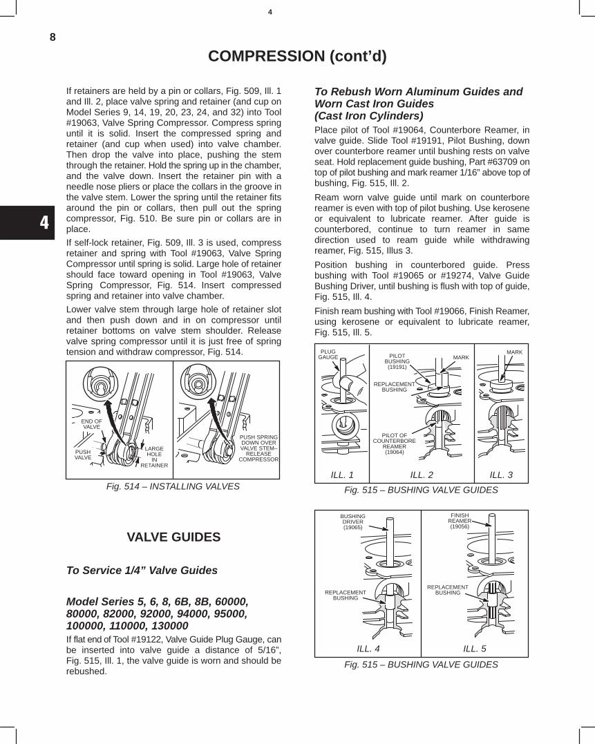
8
4
COMPRESSION (cont’d)
If retainers are held by a pin or collars, Fig. 509, Ill. 1and Ill. 2, place valve spring and retainer (and cup onModel Series 9, 14, 19, 20, 23, 24, and 32) into Tool#19063, Valve Spring Compressor. Compress springuntil it is solid. Insert the compressed spring andretainer (and cup when used) into valve chamber.Then drop the valve into place, pushing the stemthrough the retainer. Hold the spring up in the chamber,and the valve down. Insert the retainer pin with aneedle nose pliers or place the collars in the groove inthe valve stem. Lower the spring until the retainer fitsaround the pin or collars, then pull out the springcompressor, Fig. 510. Be sure pin or collars are inplace.
If self-lock retainer, Fig. 509, Ill. 3 is used, compressretainer and spring with Tool #19063, Valve SpringCompressor until spring is solid. Large hole of retainershould face toward opening in Tool #19063, ValveSpring Compressor, Fig. 514. Insert compressedspring and retainer into valve chamber.
Lower valve stem through large hole of retainer slotand then push down and in on compressor untilretainer bottoms on valve stem shoulder. Releasevalve spring compressor until it is just free of springtension and withdraw compressor, Fig. 514.
Fig. 514 – INSTALLING VALVES
LARGEHOLE
INRETAINER
PUSHVALVE
END OFVALVE
PUSH SPRINGDOWN OVERVALVE STEM–
RELEASECOMPRESSOR
VALVE GUIDES
To Service 1/4” Valve Guides
Model Series 5, 6, 8, 6B, 8B, 60000,80000, 82000, 92000, 94000, 95000,100000, 110000, 130000If flat end of Tool #19122, Valve Guide Plug Gauge, canbe inserted into valve guide a distance of 5/16”,Fig. 515, Ill. 1, the valve guide is worn and should berebushed.
To Rebush Worn Aluminum Guides andWorn Cast Iron Guides(Cast Iron Cylinders)Place pilot of Tool #19064, Counterbore Reamer, invalve guide. Slide Tool #19191, Pilot Bushing, downover counterbore reamer until bushing rests on valveseat. Hold replacement guide bushing, Part #63709 ontop of pilot bushing and mark reamer 1/16” above top ofbushing, Fig. 515, Ill. 2.
Ream worn valve guide until mark on counterborereamer is even with top of pilot bushing. Use keroseneor equivalent to lubricate reamer. After guide iscounterbored, continue to turn reamer in samedirection used to ream guide while withdrawingreamer, Fig. 515, Illus 3.
Position bushing in counterbored guide. Pressbushing with Tool #19065 or #19274, Valve GuideBushing Driver, until bushing is flush with top of guide,Fig. 515, Ill. 4.
Finish ream bushing with Tool #19066, Finish Reamer,using kerosene or equivalent to lubricate reamer,Fig. 515, Ill. 5.
ILL. 1 ILL. 2 ILL. 3
PLUGGAUGE MARKPILOT
BUSHING(19191)
REPLACEMENTBUSHING
PILOT OFCOUNTERBORE
REAMER(19064)
MARK
Fig. 515 – BUSHING VALVE GUIDES
ILL. 4 ILL. 5
BUSHINGDRIVER(19065)
REPLACEMENTBUSHING
REPLACEMENTBUSHING
FINISHREAMER(19056)
Fig. 515 – BUSHING VALVE GUIDES
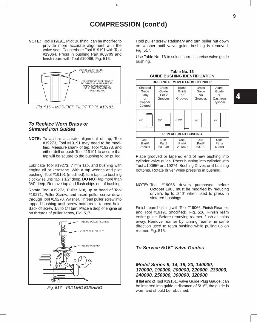
9
4
COMPRESSION (cont’d)
NOTE: Tool #19191, Pilot Bushing, can be modified toprovide more accurate alignment with thevalve seat. Counterbore Tool #19191 with Tool#19064. Press in bushing Part #63709 andfinish ream with Tool #19066, Fig. 516.
Fig. 516 – MODIFIED PILOT TOOL #19191
#19191 VALVE GUIDEPILOT BUSHING
USE #19065/#19274 DRIVERTO DRIVE IN #63709 BRASS
VALVE GUIDE BUSHINGUSE #19066 REAMER TO
FINISH REAM.
To Replace Worn Brass orSintered Iron Guides
NOTE: To assure accurate alignment of tap, Tool#19273, Tool #19191 may need to be modi-fied. Measure shank of tap, Tool #19273, andeither drill or bush Tool #19191 to assure thattap will be square to the bushing to be pulled.
Lubricate Tool #19273, 7 mm Tap, and bushing withengine oil or kerosene. With a tap wrench and pilotbushing, Tool #19191 (modified), turn tap into bushingclockwise until tap is 1/2” deep. DO NOT tap more than3/4” deep. Remove tap and flush chips out of bushing.
Rotate Tool #19272, Puller Nut, up to head of Tool#19271, Puller Screw, and insert puller screw downthrough Tool #19270, Washer. Thread puller screw intotapped bushing until screw bottoms in tapped hole.Back off screw 1/8 to 1/4 turn. Place a drop of engine oilon threads of puller screw, Fig. 517.
Fig. 517 – PULLING BUSHING
#19270 WASHER
#19271 PULLER SCREW
#19272 PULLER NUT
Hold puller screw stationary and turn puller nut downon washer until valve guide bushing is removed,Fig. 517.
Use Table No. 16 to select correct service valve guidebushing.
Table No. 16GUIDE BUSHING IDENTIFICATION
BUSHING REMOVED FROM CYLINDER
SinteredGuideGray
orCopperColored
BrassGuide1 or 2
Grooves
BrassGuide1 or 2
Grooves
BrassGuide
NoGrooves
Alum.Guide
or Cast IronCylinder
3/4” 3/4” 1–1/16” 3/4” 3/4”
REPLACEMENT BUSHING
Use Part#
262001
Use Part#
231348
Use Part#
231349
Use Part#63709
Use Part#63709
Place grooved or tapered end of new bushing intocylinder valve guide. Press bushing into cylinder withTool #19065* or #19274, Bushing Driver, until bushingbottoms. Rotate driver while pressing in bushing.
NOTE: Tool #19065 drivers purchased beforeOctober 1983 must be modified by reducingdriver’s tip to .240” when used to press insintered bushings.
Finish ream bushing with Tool #19066, Finish Reamer,and Tool #19191 (modified), Fig. 516. Finish reamentire guide. Before removing reamer, flush all chipsaway. Remove reamer by turning reamer in samedirection used to ream bushing while pulling up onreamer, Fig. 515.
To Service 5/16” Valve Guides
Model Series 9, 14, 19, 23, 140000,170000, 190000, 200000, 220000, 230000,240000, 250000, 300000, 320000If flat end of Tool #19151, Valve Guide Plug Gauge, canbe inserted into guide a distance of 5/16”, the guide isworn and should be rebushed.
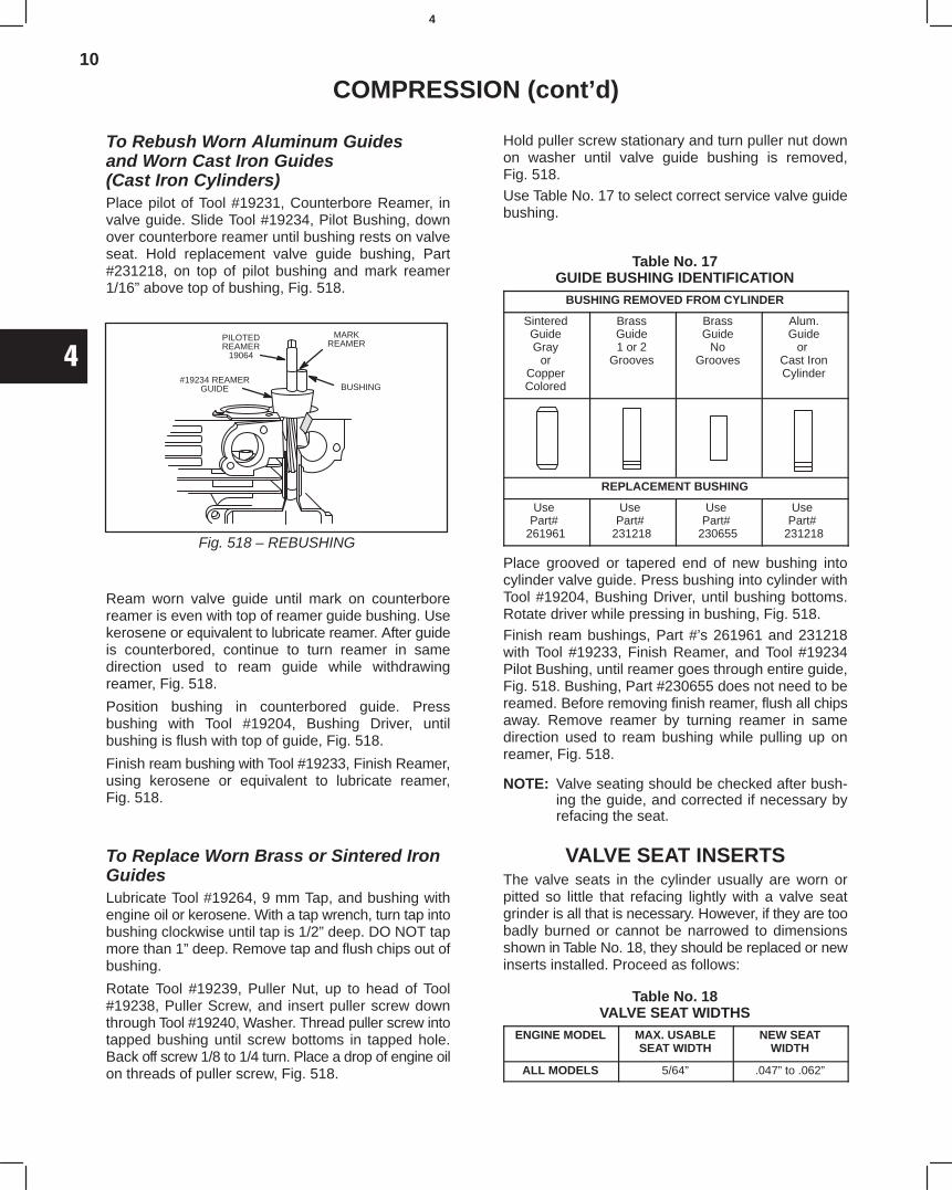
10
4
COMPRESSION (cont’d)
To Rebush Worn Aluminum Guidesand Worn Cast Iron Guides(Cast Iron Cylinders)Place pilot of Tool #19231, Counterbore Reamer, invalve guide. Slide Tool #19234, Pilot Bushing, downover counterbore reamer until bushing rests on valveseat. Hold replacement valve guide bushing, Part#231218, on top of pilot bushing and mark reamer1/16” above top of bushing, Fig. 518.
Fig. 518 – REBUSHING
PILOTEDREAMER
19064
MARKREAMER
BUSHING#19234 REAMER
GUIDE
Ream worn valve guide until mark on counterborereamer is even with top of reamer guide bushing. Usekerosene or equivalent to lubricate reamer. After guideis counterbored, continue to turn reamer in samedirection used to ream guide while withdrawingreamer, Fig. 518.
Position bushing in counterbored guide. Pressbushing with Tool #19204, Bushing Driver, untilbushing is flush with top of guide, Fig. 518.
Finish ream bushing with Tool #19233, Finish Reamer,using kerosene or equivalent to lubricate reamer,Fig. 518.
To Replace Worn Brass or Sintered IronGuidesLubricate Tool #19264, 9 mm Tap, and bushing withengine oil or kerosene. With a tap wrench, turn tap intobushing clockwise until tap is 1/2” deep. DO NOT tapmore than 1” deep. Remove tap and flush chips out ofbushing.
Rotate Tool #19239, Puller Nut, up to head of Tool#19238, Puller Screw, and insert puller screw downthrough Tool #19240, Washer. Thread puller screw intotapped bushing until screw bottoms in tapped hole.Back off screw 1/8 to 1/4 turn. Place a drop of engine oilon threads of puller screw, Fig. 518.
Hold puller screw stationary and turn puller nut downon washer until valve guide bushing is removed,Fig. 518.Use Table No. 17 to select correct service valve guidebushing.
Table No. 17GUIDE BUSHING IDENTIFICATION
BUSHING REMOVED FROM CYLINDER
SinteredGuideGray
orCopperColored
BrassGuide1 or 2
Grooves
BrassGuide
NoGrooves
Alum.Guide
or Cast IronCylinder
REPLACEMENT BUSHING
Use Part#
261961
Use Part#
231218
Use Part#
230655
Use Part#
231218
Place grooved or tapered end of new bushing intocylinder valve guide. Press bushing into cylinder withTool #19204, Bushing Driver, until bushing bottoms.Rotate driver while pressing in bushing, Fig. 518.Finish ream bushings, Part #’s 261961 and 231218with Tool #19233, Finish Reamer, and Tool #19234Pilot Bushing, until reamer goes through entire guide,Fig. 518. Bushing, Part #230655 does not need to bereamed. Before removing finish reamer, flush all chipsaway. Remove reamer by turning reamer in samedirection used to ream bushing while pulling up onreamer, Fig. 518.
NOTE: Valve seating should be checked after bush-ing the guide, and corrected if necessary byrefacing the seat.
VALVE SEAT INSERTSThe valve seats in the cylinder usually are worn orpitted so little that refacing lightly with a valve seatgrinder is all that is necessary. However, if they are toobadly burned or cannot be narrowed to dimensionsshown in Table No. 18, they should be replaced or newinserts installed. Proceed as follows:
Table No. 18VALVE SEAT WIDTHS
ENGINE MODEL MAX. USABLESEAT WIDTH
NEW SEATWIDTH
ALL MODELS 5/64” .047” to .062”
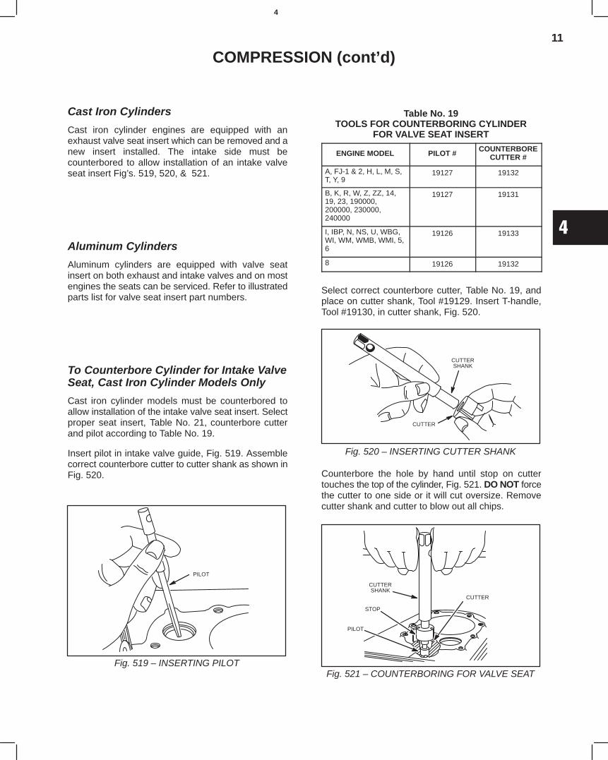
11
4
COMPRESSION (cont’d)
Cast Iron Cylinders
Cast iron cylinder engines are equipped with anexhaust valve seat insert which can be removed and anew insert installed. The intake side must becounterbored to allow installation of an intake valveseat insert Fig’s. 519, 520, & 521.
Aluminum Cylinders
Aluminum cylinders are equipped with valve seatinsert on both exhaust and intake valves and on mostengines the seats can be serviced. Refer to illustratedparts list for valve seat insert part numbers.
To Counterbore Cylinder for Intake ValveSeat, Cast Iron Cylinder Models Only
Cast iron cylinder models must be counterbored toallow installation of the intake valve seat insert. Selectproper seat insert, Table No. 21, counterbore cutterand pilot according to Table No. 19.
Insert pilot in intake valve guide, Fig. 519. Assemblecorrect counterbore cutter to cutter shank as shown inFig. 520.
Fig. 519 – INSERTING PILOT
PILOT
Table No. 19TOOLS FOR COUNTERBORING CYLINDER
FOR VALVE SEAT INSERT
ENGINE MODEL PILOT #COUNTERBORE
CUTTER #
A, FJ-1 & 2, H, L, M, S,T, Y, 9
19127 19132
B, K, R, W, Z, ZZ, 14,19, 23, 190000,200000, 230000,240000
19127 19131
I, IBP, N, NS, U, WBG,WI, WM, WMB, WMI, 5,6
19126 19133
8 19126 19132
Select correct counterbore cutter, Table No. 19, andplace on cutter shank, Tool #19129. Insert T-handle,Tool #19130, in cutter shank, Fig. 520.
CUTTERSHANK
CUTTER
Fig. 520 – INSERTING CUTTER SHANK
Counterbore the hole by hand until stop on cuttertouches the top of the cylinder, Fig. 521. DO NOT forcethe cutter to one side or it will cut oversize. Removecutter shank and cutter to blow out all chips.
CUTTERSHANK
CUTTER
PILOT
STOP
Fig. 521 – COUNTERBORING FOR VALVE SEAT
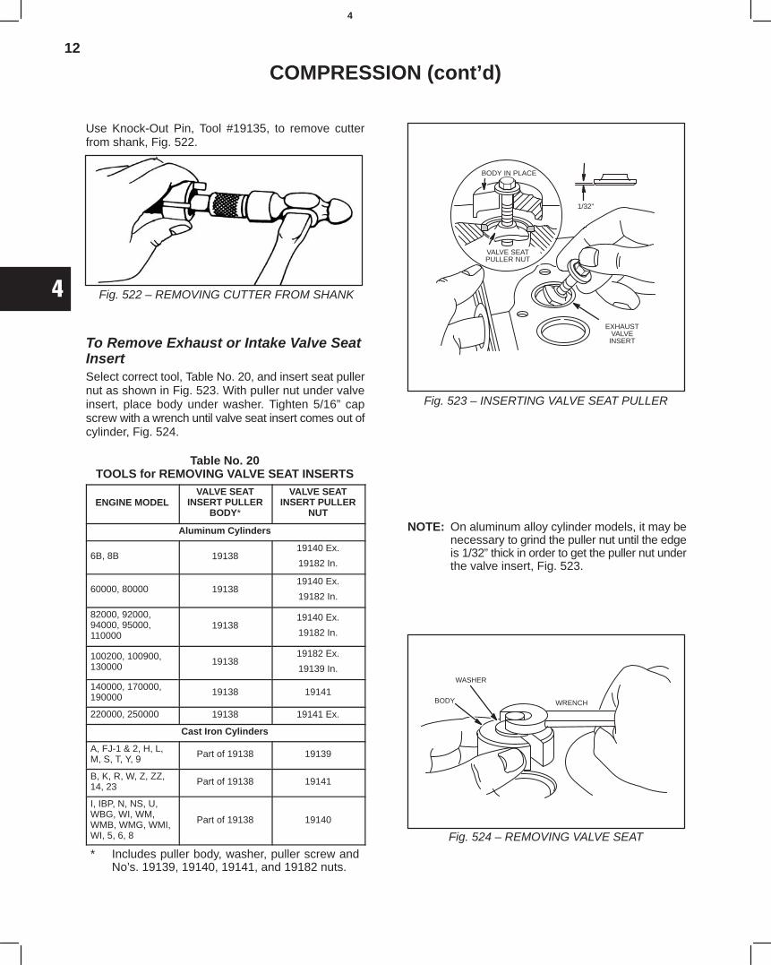
12
4
COMPRESSION (cont’d)
Use Knock-Out Pin, Tool #19135, to remove cutterfrom shank, Fig. 522.
Fig. 522 – REMOVING CUTTER FROM SHANK
To Remove Exhaust or Intake Valve SeatInsertSelect correct tool, Table No. 20, and insert seat pullernut as shown in Fig. 523. With puller nut under valveinsert, place body under washer. Tighten 5/16” capscrew with a wrench until valve seat insert comes out ofcylinder, Fig. 524.
Table No. 20TOOLS for REMOVING VALVE SEAT INSERTS
ENGINE MODELVALVE SEAT
INSERT PULLERBODY*
VALVE SEATINSERT PULLER
NUT
Aluminum Cylinders
6B, 8B 1913819140 Ex.
19182 In.
60000, 80000 1913819140 Ex.
19182 In.
82000, 92000,94000, 95000,110000
1913819140 Ex.
19182 In.
100200, 100900,130000 19138
19182 Ex.
19139 In.
140000, 170000,190000 19138 19141
220000, 250000 19138 19141 Ex.
Cast Iron Cylinders
A, FJ-1 & 2, H, L,M, S, T, Y, 9 Part of 19138 19139
B, K, R, W, Z, ZZ,14, 23 Part of 19138 19141
I, IBP, N, NS, U,WBG, WI, WM,WMB, WMG, WMI,WI, 5, 6, 8
Part of 19138 19140
* Includes puller body, washer, puller screw andNo’s. 19139, 19140, 19141, and 19182 nuts.
Fig. 523 – INSERTING VALVE SEAT PULLER
1/32”
BODY IN PLACE
VALVE SEATPULLER NUT
EXHAUSTVALVE
INSERT
NOTE: On aluminum alloy cylinder models, it may benecessary to grind the puller nut until the edgeis 1/32” thick in order to get the puller nut underthe valve insert, Fig. 523.
Fig. 524 – REMOVING VALVE SEAT
WASHER
WRENCHBODY
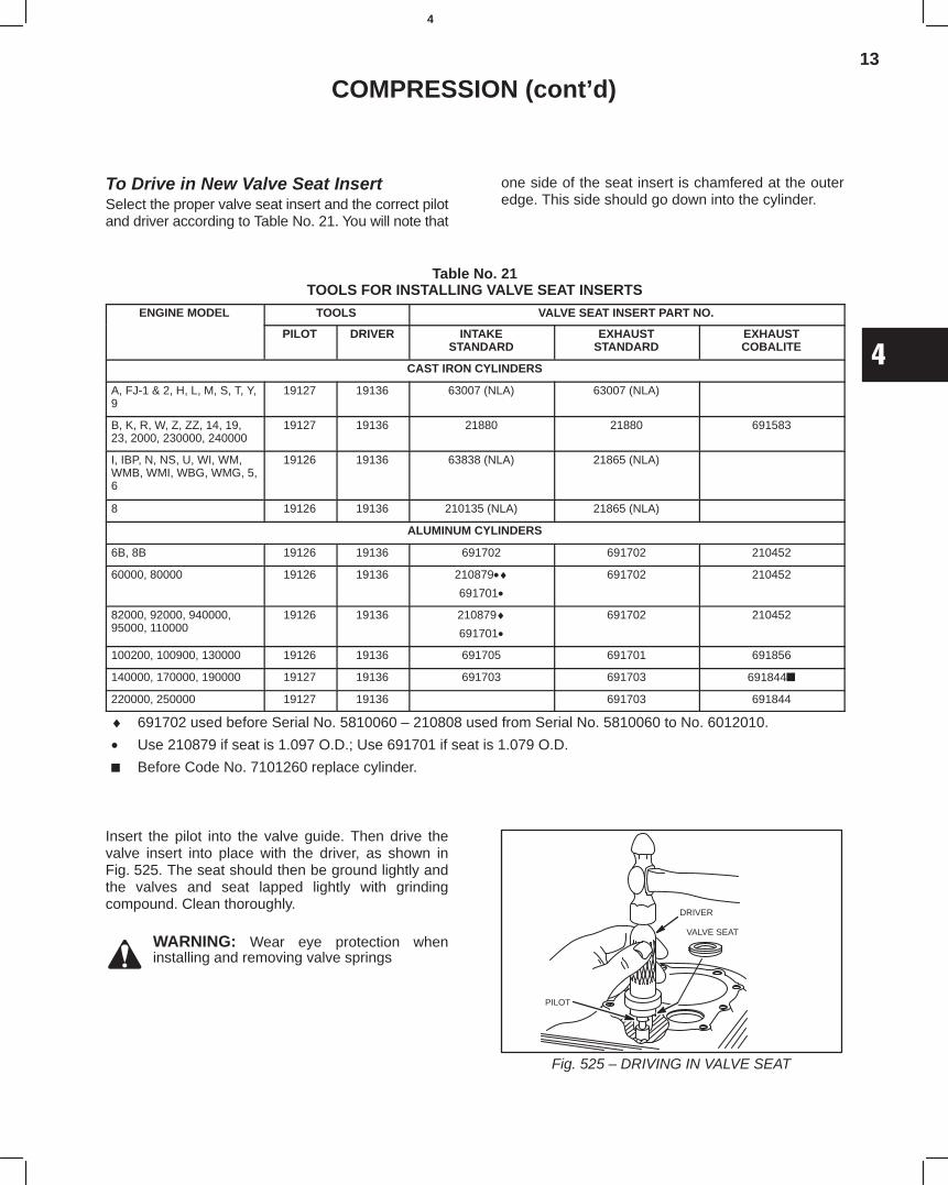
13
4
COMPRESSION (cont’d)
To Drive in New Valve Seat InsertSelect the proper valve seat insert and the correct pilotand driver according to Table No. 21. You will note that
one side of the seat insert is chamfered at the outeredge. This side should go down into the cylinder.
Table No. 21TOOLS FOR INSTALLING VALVE SEAT INSERTS
ENGINE MODEL TOOLS VALVE SEAT INSERT PART NO.
PILOT DRIVER INTAKESTANDARD
EXHAUSTSTANDARD
EXHAUSTCOBALITE
CAST IRON CYLINDERS
A, FJ-1 & 2, H, L, M, S, T, Y,9
19127 19136 63007 (NLA) 63007 (NLA)
B, K, R, W, Z, ZZ, 14, 19,23, 2000, 230000, 240000
19127 19136 21880 21880 691583
I, IBP, N, NS, U, WI, WM,WMB, WMI, WBG, WMG, 5,6
19126 19136 63838 (NLA) 21865 (NLA)
8 19126 19136 210135 (NLA) 21865 (NLA)
ALUMINUM CYLINDERS
6B, 8B 19126 19136 691702 691702 210452
60000, 80000 19126 19136 210879•♦691701•
691702 210452
82000, 92000, 940000,95000, 110000
19126 19136 210879♦691701•
691702 210452
100200, 100900, 130000 19126 19136 691705 691701 691856
140000, 170000, 190000 19127 19136 691703 691703 691844
220000, 250000 19127 19136 691703 691844
♦ 691702 used before Serial No. 5810060 – 210808 used from Serial No. 5810060 to No. 6012010.
• Use 210879 if seat is 1.097 O.D.; Use 691701 if seat is 1.079 O.D.
Before Code No. 7101260 replace cylinder.
Insert the pilot into the valve guide. Then drive thevalve insert into place with the driver, as shown inFig. 525. The seat should then be ground lightly andthe valves and seat lapped lightly with grindingcompound. Clean thoroughly.
WARNING: Wear eye protection wheninstalling and removing valve springs
Fig. 525 – DRIVING IN VALVE SEAT
DRIVER
VALVE SEAT
PILOT
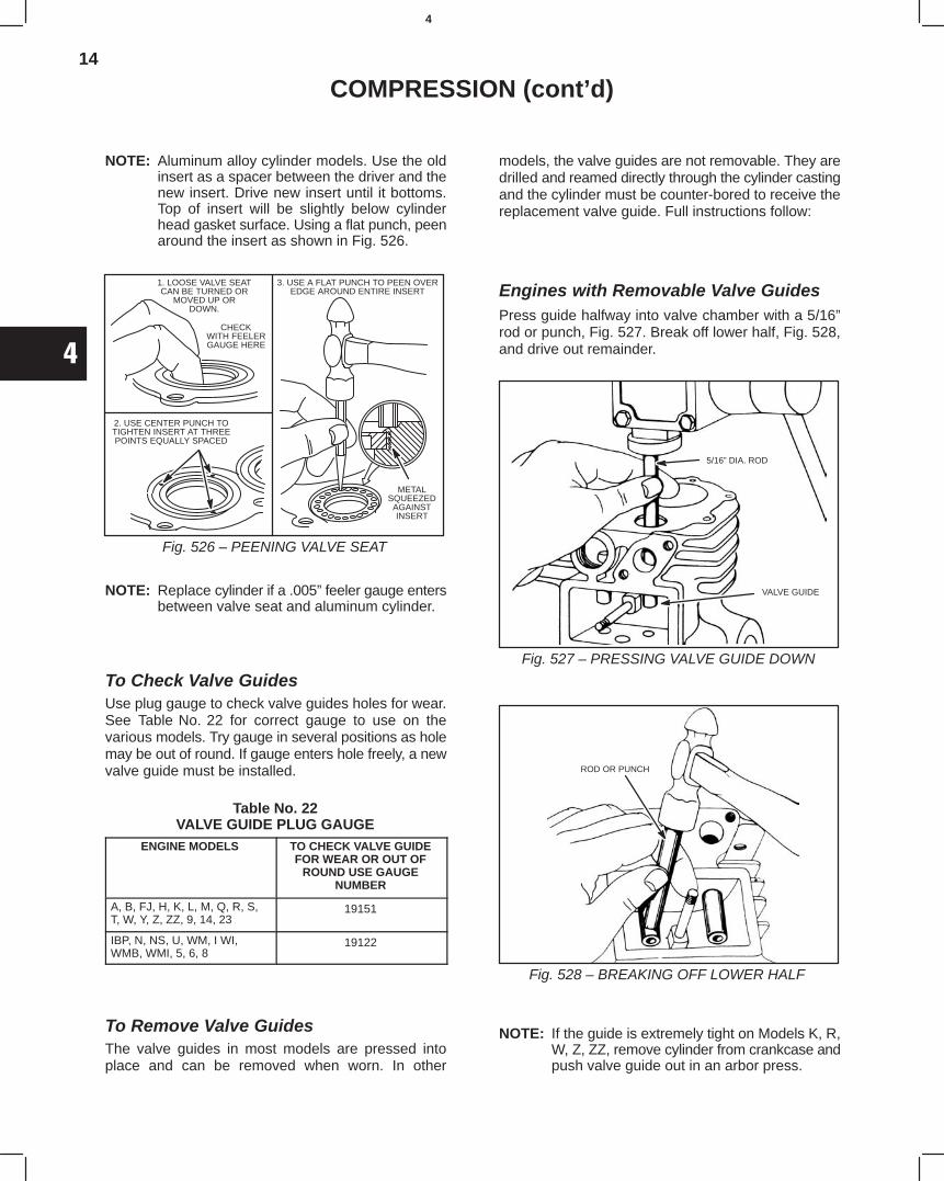
14
4
COMPRESSION (cont’d)
NOTE: Aluminum alloy cylinder models. Use the oldinsert as a spacer between the driver and thenew insert. Drive new insert until it bottoms.Top of insert will be slightly below cylinderhead gasket surface. Using a flat punch, peenaround the insert as shown in Fig. 526.
Fig. 526 – PEENING VALVE SEAT
1. LOOSE VALVE SEATCAN BE TURNED OR
MOVED UP ORDOWN.
CHECKWITH FEELERGAUGE HERE
2. USE CENTER PUNCH TOTIGHTEN INSERT AT THREEPOINTS EQUALLY SPACED
3. USE A FLAT PUNCH TO PEEN OVEREDGE AROUND ENTIRE INSERT
METALSQUEEZED
AGAINSTINSERT
NOTE: Replace cylinder if a .005” feeler gauge entersbetween valve seat and aluminum cylinder.
To Check Valve GuidesUse plug gauge to check valve guides holes for wear.See Table No. 22 for correct gauge to use on thevarious models. Try gauge in several positions as holemay be out of round. If gauge enters hole freely, a newvalve guide must be installed.
Table No. 22VALVE GUIDE PLUG GAUGE
ENGINE MODELS TO CHECK VALVE GUIDEFOR WEAR OR OUT OF
ROUND USE GAUGENUMBER
A, B, FJ, H, K, L, M, Q, R, S,T, W, Y, Z, ZZ, 9, 14, 23
19151
IBP, N, NS, U, WM, I WI,WMB, WMI, 5, 6, 8
19122
To Remove Valve GuidesThe valve guides in most models are pressed intoplace and can be removed when worn. In other
models, the valve guides are not removable. They aredrilled and reamed directly through the cylinder castingand the cylinder must be counter-bored to receive thereplacement valve guide. Full instructions follow:
Engines with Removable Valve GuidesPress guide halfway into valve chamber with a 5/16”rod or punch, Fig. 527. Break off lower half, Fig. 528,and drive out remainder.
Fig. 527 – PRESSING VALVE GUIDE DOWN
5/16” DIA. ROD
VALVE GUIDE
Fig. 528 – BREAKING OFF LOWER HALF
ROD OR PUNCH
NOTE: If the guide is extremely tight on Models K, R,W, Z, ZZ, remove cylinder from crankcase andpush valve guide out in an arbor press.
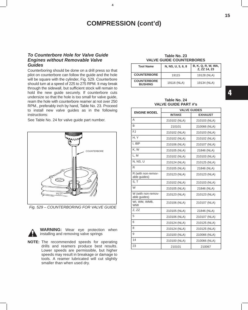
15
4
COMPRESSION (cont’d)
To Counterbore Hole for Valve GuideEngines without Removable ValveGuidesCounterboring should be done on a drill press so thatpilot on counterbore can follow the guide and the holewill be square with the cylinder, Fig. 529. Counterboreshould turn at a speed of 225 to 275 RPM. It may breakthrough the sidewall, but sufficient stock will remain tohold the new guide securely. If counterbore cutsundersize so that the hole is too small for valve guide,ream the hole with counterbore reamer at not over 250RPM., preferably inch by hand, Table No. 23. Proceedto install new valve guides as in the followinginstructions:See Table No. 24 for valve guide part number.
Fig. 529 – COUNTERBORING FOR VALVE GUIDE
COUNTERBORE
PILOT
WARNING: Wear eye protection wheninstalling and removing valve springs
NOTE: The recommended speeds for operatingdrills and reamers produce best results.Lower speeds are permissible, but higherspeeds may result in breakage or damage totools. A reamer lubricated will cut slightlysmaller than when used dry.
Table No. 23VALVE GUIDE COUNTERBORES
Tool Name N, NS, U, 5, 6, 8 B, K, Q, R, W, WA,Z, ZZ 14, 23
COUNTERBORE 19115 19128 (NLA)
COUNTERBOREBUSHING 19116 (NLA) 19134 (NLA)
Table No. 24VALVE GUIDE PART #’s
ENGINE MODELVALVE GUIDES
ENGINE MODELINTAKE EXHAUST
A 210102 (NLA) 210103 (NLA)
B 210101 210066 (NLA)
FJ 210102 (NLA) 210103 (NLA)
H, Y 210102 (NLA) 210102 (NLA)
I, IBP 210106 (NLA) 210107 (NLA)
K, W 210105 (NLA) 21846 (NLA)
L, M 210102 (NLA) 210103 (NLA)
N, NS, U 210124 (NLA) 210125 (NLA)
R 210105 (NLA) 21846 (NLA)
R (with non-remov-able guides)
210123 (NLA) 210123 (NLA)
S, T 210102 (NLA) 210103 (NLA)
W 210105 (NLA) 21846 (NLA)
W (with non-remov-able guides)
210123 (NLA) 210123 (NLA)
WI, WM, WMB,WMI
210106 (NLA) 210107 (NLA)
Z, ZZ 210105 (NLA) 21846 (NLA)
5 210106 (NLA) 210107 (NLA)
6 210124 (NLA) 210125 (NLA)
8 210124 (NLA) 210125 (NLA)
9 210100 (NLA) 210066 (NLA)
14 210100 (NLA) 210066 (NLA)
23 210101 210067
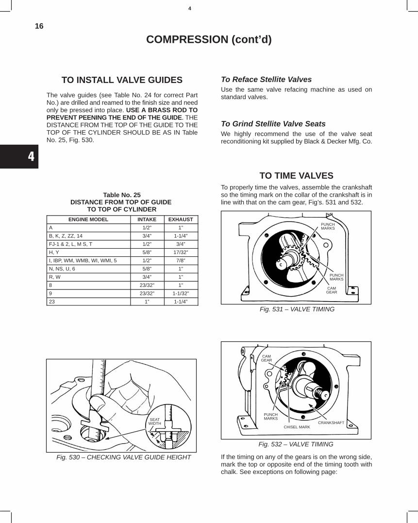
16
4
COMPRESSION (cont’d)
TO INSTALL VALVE GUIDES
The valve guides (see Table No. 24 for correct PartNo.) are drilled and reamed to the finish size and needonly be pressed into place. USE A BRASS ROD TOPREVENT PEENING THE END OF THE GUIDE. THEDISTANCE FROM THE TOP OF THE GUIDE TO THETOP OF THE CYLINDER SHOULD BE AS IN TableNo. 25, Fig. 530.
Table No. 25DISTANCE FROM TOP OF GUIDE
TO TOP OF CYLINDER
ENGINE MODEL INTAKE EXHAUST
A 1/2” 1”
B, K, Z, ZZ, 14 3/4” 1-1/4”
FJ-1 & 2, L, M S, T 1/2” 3/4”
H, Y 5/8” 17/32”
I, IBP, WM, WMB, WI, WMI, 5 1/2” 7/8”
N, NS, U, 6 5/8” 1”
R, W 3/4” 1”
8 23/32” 1”
9 23/32” 1-1/32”
23 1” 1-1/4”
Fig. 530 – CHECKING VALVE GUIDE HEIGHT
SEATWIDTH
To Reface Stellite ValvesUse the same valve refacing machine as used onstandard valves.
To Grind Stellite Valve SeatsWe highly recommend the use of the valve seatreconditioning kit supplied by Black & Decker Mfg. Co.
TO TIME VALVESTo properly time the valves, assemble the crankshaftso the timing mark on the collar of the crankshaft is inline with that on the cam gear, Fig’s. 531 and 532.
Fig. 531 – VALVE TIMING
PUNCHMARKS
CAMGEAR
PUNCHMARKS
Fig. 532 – VALVE TIMING
CHISEL MARK
CAMGEAR
PUNCHMARKS
CRANKSHAFT
If the timing on any of the gears is on the wrong side,mark the top or opposite end of the timing tooth withchalk. See exceptions on following page:
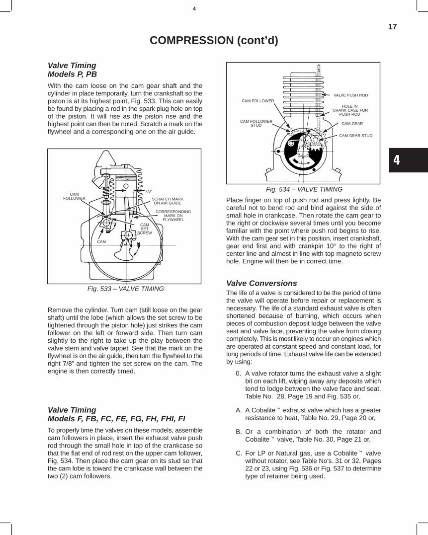
17
4
COMPRESSION (cont’d)
Valve TimingModels P, PBWith the cam loose on the cam gear shaft and thecylinder in place temporarily, turn the crankshaft so thepiston is at its highest point, Fig. 533. This can easilybe found by placing a rod in the spark plug hole on topof the piston. It will rise as the piston rise and thehighest point can then be noted. Scratch a mark on theflywheel and a corresponding one on the air guide.
Fig. 533 – VALVE TIMING
CAMFOLLOWER SCRATCH MARK
ON AIR GUIDE
CORRESPONDINGMARK ON
FLYWHEELCAMSET
SCREW
CAM
7/8”
Remove the cylinder. Turn cam (still loose on the gearshaft) until the lobe (which allows the set screw to betightened through the piston hole) just strikes the camfollower on the left or forward side. Then turn camslightly to the right to take up the play between thevalve stem and valve tappet. See that the mark on theflywheel is on the air guide, then turn the flywheel to theright 7/8” and tighten the set screw on the cam. Theengine is then correctly timed.
Valve TimingModels F, FB, FC, FE, FG, FH, FHI, FITo properly time the valves on these models, assemblecam followers in place, insert the exhaust valve pushrod through the small hole in top of the crankcase sothat the flat end of rod rest on the upper cam follower,Fig. 534. Then place the cam gear on its stud so thatthe cam lobe is toward the crankcase wall between thetwo (2) cam followers.
CAM FOLLOWER
CAM FOLLOWERSTUD
VALVE PUSH ROD
HOLE IN CRANK CASE FOR
PUSH ROD
CAM GEAR
CAM GEAR STUD
Fig. 534 – VALVE TIMING
Place finger on top of push rod and press lightly. Becareful not to bend rod and bind against the side ofsmall hole in crankcase. Then rotate the cam gear tothe right or clockwise several times until you becomefamiliar with the point where push rod begins to rise.With the cam gear set in this position, insert crankshaft,gear end first and with crankpin 10° to the right ofcenter line and almost in line with top magneto screwhole. Engine will then be in correct time.
Valve ConversionsThe life of a valve is considered to be the period of timethe valve will operate before repair or replacement isnecessary. The life of a standard exhaust valve is oftenshortened because of burning, which occurs whenpieces of combustion deposit lodge between the valveseat and valve face, preventing the valve from closingcompletely. This is most likely to occur on engines whichare operated at constant speed and constant load, forlong periods of time. Exhaust valve life can be extendedby using:
0. A valve rotator turns the exhaust valve a slightbit on each lift, wiping away any deposits whichtend to lodge between the valve face and seat,Table No. 28, Page 19 and Fig. 535 or,
A. A Cobalite exhaust valve which has a greaterresistance to heat, Table No. 29, Page 20 or,
B. Or a combination of both the rotator andCobalite valve, Table No. 30, Page 21 or,
C. For LP or Natural gas, use a Cobalite valvewithout rotator, see Table No’s. 31 or 32, Pages22 or 23, using Fig. 536 or Fig. 537 to determinetype of retainer being used.
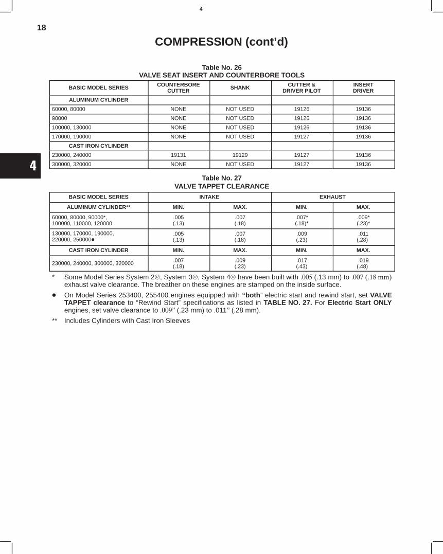
18
4
COMPRESSION (cont’d)
Table No. 26VALVE SEAT INSERT AND COUNTERBORE TOOLS
BASIC MODEL SERIES COUNTERBORECUTTER SHANK CUTTER &
DRIVER PILOTINSERTDRIVER
ALUMINUM CYLINDER
60000, 80000 NONE NOT USED 19126 19136
90000 NONE NOT USED 19126 19136
100000, 130000 NONE NOT USED 19126 19136
170000, 190000 NONE NOT USED 19127 19136
CAST IRON CYLINDER
230000, 240000 19131 19129 19127 19136
300000, 320000 NONE NOT USED 19127 19136
Table No. 27VALVE TAPPET CLEARANCE
BASIC MODEL SERIES INTAKE EXHAUST
ALUMINUM CYLINDER** MIN. MAX. MIN. MAX.
60000, 80000, 90000*,100000, 110000, 120000
.005(.13)
.007(.18)
.007*(.18)*
.009*(.23)*
130000, 170000, 190000,220000, 250000
.005(.13)
.007(.18)
.009(.23)
.011(.28)*
CAST IRON CYLINDER MIN. MAX. MIN. MAX.
230000, 240000, 300000, 320000 .007(.18)
.009(.23)
.017(.43)
.019(.48)*
* Some Model Series System 2, System 3, System 4 have been built with (.13 mm) to exhaust valve clearance. The breather on these engines are stamped on the inside surface.
On Model Series 253400, 255400 engines equipped with “both” electric start and rewind start, set VALVETAPPET clearance to “Rewind Start” specifications as listed in TABLE NO. 27. For Electric Start ONLYengines, set valve clearance to (.23 mm) to .011(.28 mm).
** Includes Cylinders with Cast Iron Sleeves
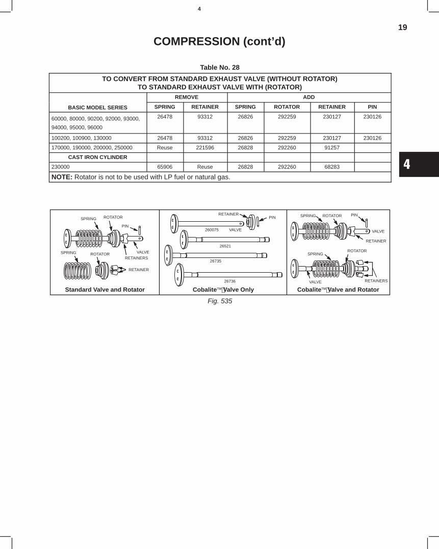
19
4
COMPRESSION (cont’d)
Table No. 28
TO CONVERT FROM STANDARD EXHAUST VALVE (WITHOUT ROTATOR)TO STANDARD EXHAUST VALVE WITH (ROTATOR)
REMOVE ADD
BASIC MODEL SERIES SPRING RETAINER SPRING ROTATOR RETAINER PIN
60000, 80000, 90200, 92000, 93000,
94000, 95000, 96000
26478 93312 26826 292259 230127 230126
100200, 100900, 130000 26478 93312 26826 292259 230127 230126
170000, 190000, 200000, 250000 Reuse 221596 26828 292260 91257
CAST IRON CYLINDER
230000 65906 Reuse 26828 292260 68283
NOTE: Rotator is not to be used with LP fuel or natural gas.
Cobalite Valve and Rotator
Fig. 535
Standard Valve and Rotator Cobalite Valve Only
SPRINGROTATOR
SPRING ROTATOR
PIN
VALVE
RETAINERS
RETAINER
SPRING
26736
26735
26521
260075 VALVE
PINRETAINER PIN
VALVE
RETAINER
ROTATOR
RETAINERSVALVE
SPRING ROTATOR
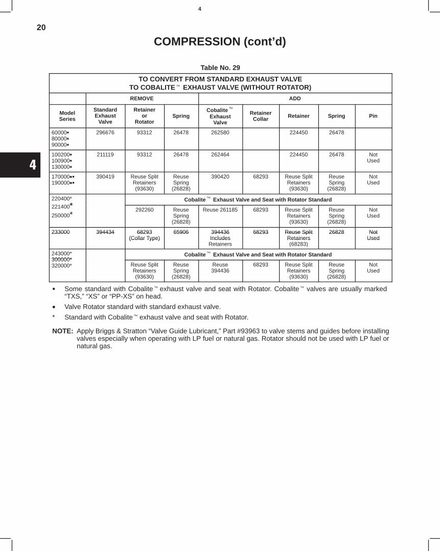
20
4
COMPRESSION (cont’d)
Table No. 29
TO CONVERT FROM STANDARD EXHAUST VALVETO COBALITE EXHAUST VALVE (WITHOUT ROTATOR)
REMOVE ADD
ModelSeries
StandardExhaust
Valve
Retaineror
RotatorSpring
CobaliteExhaust
Valve
RetainerCollar Retainer Spring Pin
600008000090000
296676 93312 26478 262580 224450 26478
100200100900130000
211119 93312 26478 262464 224450 26478 NotUsed
170000•190000•
390419 Reuse SplitRetainers(93630)
ReuseSpring(26828)
390420 68293 Reuse SplitRetainers(93630)
ReuseSpring
(26828)
NotUsed
220400*
221400*Cobalite Exhaust Valve and Seat with Rotator Standard
221400*250000*
292260 ReuseSpring(26828)
Reuse 261185 68293 Reuse SplitRetainers(93630)
ReuseSpring
(26828)
NotUsed
233000 394434 68293 65906 394436 68293 Reuse Split 26828 Not233000 394434 68293(Collar Type)
65906 394436Includes
68293 Reuse SplitRetainers
26828 NotUsed(Collar Type) Includes
RetainersRetainers(68283)
Used
243000*300000*
Cobalite Exhaust Valve and Seat with Rotator Standard300000*320000* Reuse Split
Retainers(93630)
ReuseSpring(26828)
Reuse394436
68293 Reuse SplitRetainers(93630)
ReuseSpring
(26828)
NotUsed
Some standard with Cobalite exhaust valve and seat with Rotator. Cobalite valves are usually marked“TXS,” “XS” or “PP-XS” on head.
• Valve Rotator standard with standard exhaust valve.
* Standard with Cobalite exhaust valve and seat with Rotator.
NOTE: Apply Briggs & Stratton “Valve Guide Lubricant,” Part #93963 to valve stems and guides before installingvalves especially when operating with LP fuel or natural gas. Rotator should not be used with LP fuel ornatural gas.
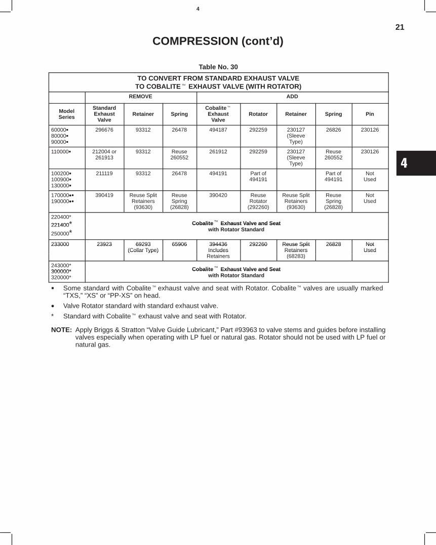
21
4
COMPRESSION (cont’d)
Table No. 30
TO CONVERT FROM STANDARD EXHAUST VALVETO COBALITE EXHAUST VALVE (WITH ROTATOR)
REMOVE ADD
ModelSeries
StandardExhaust
ValveRetainer Spring
CobaliteExhaust
ValveRotator Retainer Spring Pin
600008000090000
296676 93312 26478 494187 292259 230127(SleeveType)
26826 230126
110000 212004 or261913
93312 Reuse260552
261912 292259 230127(SleeveType)
Reuse260552
230126
100200100900130000
211119 93312 26478 494191 Part of494191
Part of494191
NotUsed
170000•190000•
390419 Reuse SplitRetainers(93630)
ReuseSpring(26828)
390420 ReuseRotator
(292260)
Reuse SplitRetainers(93630)
ReuseSpring
(26828)
NotUsed
220400*
221400* Cobalite Exhaust Valve and Seat221400
250000*Cobalite Exhaust Valve and Seat
with Rotator Standard
233000 23923 69293 65906 394436 292260 Reuse Split 26828 Not233000 23923 69293(Collar Type)
65906 394436Includes
292260 Reuse SplitRetainers
26828 NotUsed(Collar Type) Includes
RetainersRetainers(68283)
Used
243000*300000* Cobalite Exhaust Valve and Seat300000*320000*
Cobalite Exhaust Valve and Seatwith Rotator Standard
Some standard with Cobalite exhaust valve and seat with Rotator. Cobalite valves are usually marked“TXS,” “XS” or “PP-XS” on head.
• Valve Rotator standard with standard exhaust valve.
* Standard with Cobalite exhaust valve and seat with Rotator.
NOTE: Apply Briggs & Stratton “Valve Guide Lubricant,” Part #93963 to valve stems and guides before installingvalves especially when operating with LP fuel or natural gas. Rotator should not be used with LP fuel ornatural gas.
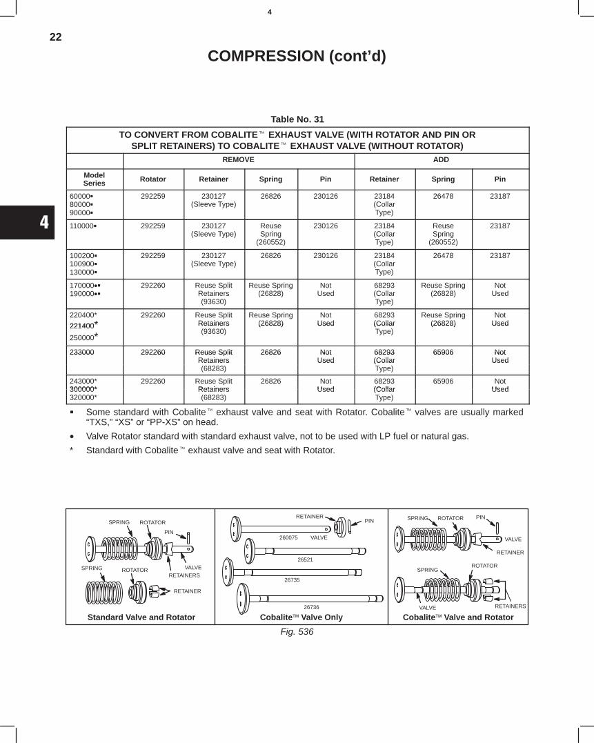
22
4
COMPRESSION (cont’d)
Table No. 31
TO CONVERT FROM COBALITE EXHAUST VALVE (WITH ROTATOR AND PIN ORSPLIT RETAINERS) TO COBALITE EXHAUST VALVE (WITHOUT ROTATOR)
REMOVE ADD
ModelSeries Rotator Retainer Spring Pin Retainer Spring Pin
600008000090000
292259 230127(Sleeve Type)
26826 230126 23184(CollarType)
26478 23187
110000 292259 230127(Sleeve Type)
ReuseSpring
(260552)
230126 23184(CollarType)
ReuseSpring
(260552)
23187
100200100900130000
292259 230127(Sleeve Type)
26826 230126 23184(CollarType)
26478 23187
170000•190000•
292260 Reuse SplitRetainers(93630)
Reuse Spring(26828)
NotUsed
68293(CollarType)
Reuse Spring(26828)
NotUsed
220400*
221400*292260 Reuse Split
RetainersReuse Spring
(26828)Not
Used68293(Collar
Reuse Spring(26828)
NotUsed221400
250000*Retainers(93630)
(26828) Used (CollarType)
(26828) Used
233000 292260 Reuse Split 26826 Not 68293 65906 Not233000 292260 Reuse SplitRetainers
26826 NotUsed
68293(Collar
65906 NotUsedRetainers
(68283)Used (Collar
Type)Used
243000*300000*
292260 Reuse SplitRetainers
26826 NotUsed
68293(Collar
65906 NotUsed300000*
320000*Retainers(68283)
Used (CollarType)
Used
Some standard with Cobalite exhaust valve and seat with Rotator. Cobalite valves are usually marked“TXS,” “XS” or “PP-XS” on head.
• Valve Rotator standard with standard exhaust valve, not to be used with LP fuel or natural gas.
* Standard with Cobalite exhaust valve and seat with Rotator.
Cobalite Valve and Rotator
Fig. 536
Standard Valve and Rotator Cobalite Valve Only
SPRINGROTATOR
SPRING ROTATOR
PIN
VALVERETAINERS
RETAINER
SPRING
26736
26735
26521
260075 VALVE
PINRETAINER PIN
VALVE
RETAINER
ROTATOR
RETAINERSVALVE
SPRING ROTATOR
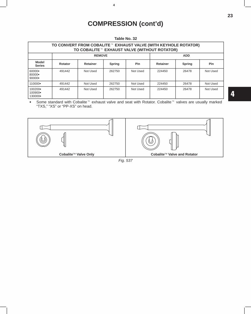
23
4
COMPRESSION (cont’d)
Table No. 32
TO CONVERT FROM COBALITE EXHAUST VALVE (WITH KEYHOLE ROTATOR)TO COBALITE EXHAUST VALVE (WITHOUT ROTATOR)
REMOVE ADD
ModelSeries Rotator Retainer Spring Pin Retainer Spring Pin
600008000090000
491442 Not Used 262750 Not Used 224450 26478 Not Used
110000 491442 Not Used 262750 Not Used 224450 26478 Not Used
100200100900130000
491442 Not Used 262750 Not Used 224450 26478 Not Used
Some standard with Cobalite exhaust valve and seat with Rotator. Cobalite valves are usually marked“TXS,” “XS” or “PP-XS” on head.
Fig. 537
Cobalite Valve Only Cobalite Valve and Rotator

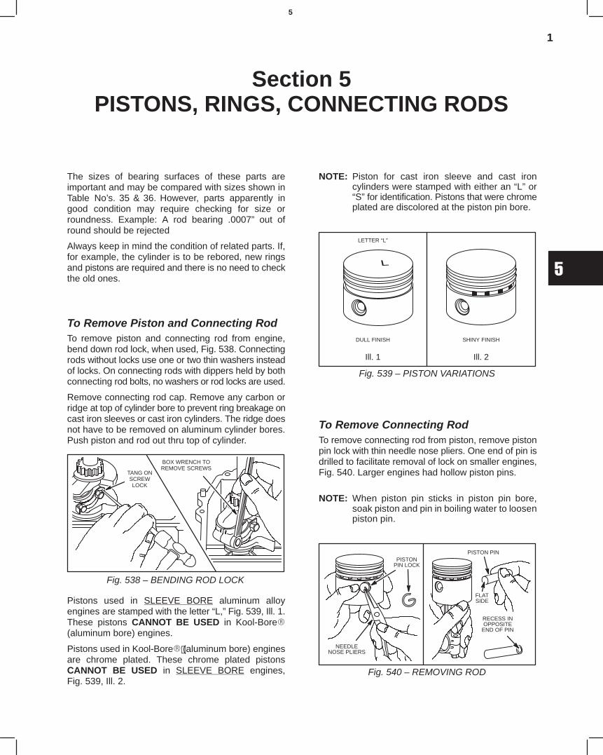
1
5
Section 5PISTONS, RINGS, CONNECTING RODS
The sizes of bearing surfaces of these parts areimportant and may be compared with sizes shown inTable No’s. 35 & 36. However, parts apparently ingood condition may require checking for size orroundness. Example: A rod bearing .0007” out ofround should be rejected
Always keep in mind the condition of related parts. If,for example, the cylinder is to be rebored, new ringsand pistons are required and there is no need to checkthe old ones.
To Remove Piston and Connecting RodTo remove piston and connecting rod from engine,bend down rod lock, when used, Fig. 538. Connectingrods without locks use one or two thin washers insteadof locks. On connecting rods with dippers held by bothconnecting rod bolts, no washers or rod locks are used.
Remove connecting rod cap. Remove any carbon orridge at top of cylinder bore to prevent ring breakage oncast iron sleeves or cast iron cylinders. The ridge doesnot have to be removed on aluminum cylinder bores.Push piston and rod out thru top of cylinder.
Fig. 538 – BENDING ROD LOCK
TANG ONSCREWLOCK
BOX WRENCH TOREMOVE SCREWS
Pistons used in SLEEVE BORE aluminum alloyengines are stamped with the letter “L,” Fig. 539, Ill. 1.These pistons CANNOT BE USED in Kool-Bore(aluminum bore) engines.
Pistons used in Kool-Bore (aluminum bore) enginesare chrome plated. These chrome plated pistonsCANNOT BE USED in SLEEVE BORE engines,Fig. 539, Ill. 2.
NOTE: Piston for cast iron sleeve and cast ironcylinders were stamped with either an “L” or“S” for identification. Pistons that were chromeplated are discolored at the piston pin bore.
Fig. 539 – PISTON VARIATIONS
LETTER “L”
DULL FINISH
Ill. 1
SHINY FINISH
Ill. 2
To Remove Connecting RodTo remove connecting rod from piston, remove pistonpin lock with thin needle nose pliers. One end of pin isdrilled to facilitate removal of lock on smaller engines,Fig. 540. Larger engines had hollow piston pins.
NOTE: When piston pin sticks in piston pin bore,soak piston and pin in boiling water to loosenpiston pin.
Fig. 540 – REMOVING ROD
NEEDLENOSE PLIERS
PISTONPIN LOCK
PISTON PIN
FLATSIDE
RECESS INOPPOSITE
END OF PIN
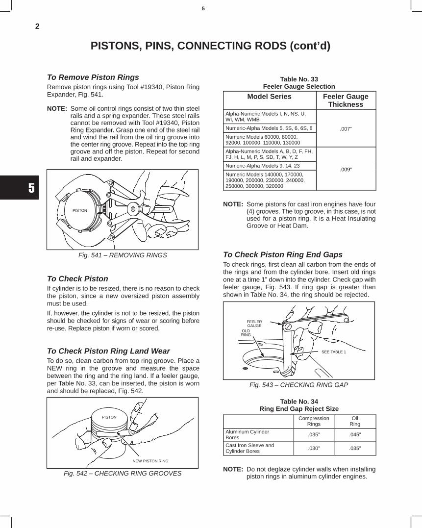
2
5
PISTONS, PINS, CONNECTING RODS (cont’d)
To Remove Piston RingsRemove piston rings using Tool #19340, Piston RingExpander, Fig. 541.
NOTE: Some oil control rings consist of two thin steelrails and a spring expander. These steel railscannot be removed with Tool #19340, PistonRing Expander. Grasp one end of the steel railand wind the rail from the oil ring groove intothe center ring groove. Repeat into the top ringgroove and off the piston. Repeat for secondrail and expander.
Fig. 541 – REMOVING RINGS
PISTON
To Check PistonIf cylinder is to be resized, there is no reason to checkthe piston, since a new oversized piston assemblymust be used.
If, however, the cylinder is not to be resized, the pistonshould be checked for signs of wear or scoring beforere-use. Replace piston if worn or scored.
To Check Piston Ring Land WearTo do so, clean carbon from top ring groove. Place aNEW ring in the groove and measure the spacebetween the ring and the ring land. If a feeler gauge,per Table No. 33, can be inserted, the piston is wornand should be replaced, Fig. 542.
Fig. 542 – CHECKING RING GROOVES
PISTON
NEW PISTON RING
Table No. 33Feeler Gauge Selection
Model Series Feeler GaugeThickness
Alpha-Numeric Models I, N, NS, U,WI, WM, WMB
Numeric-Alpha Models 5, 5S, 6, 6S, 8 .007”
Numeric Models 60000, 80000,92000, 100000, 110000, 130000
.007
Alpha-Numeric Models A, B, D, F, FH,FJ, H, L, M, P, S, SD, T, W, Y, Z
Numeric-Alpha Models 9, 14, 23009”
Numeric Models 140000, 170000,190000, 200000, 230000, 240000,250000, 300000, 320000
.009”
NOTE: Some pistons for cast iron engines have four(4) grooves. The top groove, in this case, is notused for a piston ring. It is a Heat InsulatingGroove or Heat Dam.
To Check Piston Ring End GapsTo check rings, first clean all carbon from the ends ofthe rings and from the cylinder bore. Insert old ringsone at a time 1” down into the cylinder. Check gap withfeeler gauge, Fig. 543. If ring gap is greater thanshown in Table No. 34, the ring should be rejected.
Fig. 543 – CHECKING RING GAP
ÇÇÇÇ
FEELERGAUGE
OLDRING
SEE TABLE 1
Table No. 34Ring End Gap Reject Size
CompressionRings
OilRing
Aluminum CylinderBores .035” .045”
Cast Iron Sleeve andCylinder Bores .030” .035”
NOTE: Do not deglaze cylinder walls when installingpiston rings in aluminum cylinder engines.
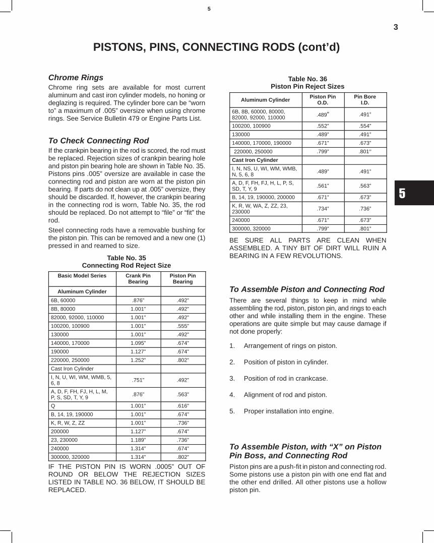
3
5
PISTONS, PINS, CONNECTING RODS (cont’d)
Chrome RingsChrome ring sets are available for most currentaluminum and cast iron cylinder models, no honing ordeglazing is required. The cylinder bore can be “wornto” a maximum of .005” oversize when using chromerings. See Service Bulletin 479 or Engine Parts List.
To Check Connecting RodIf the crankpin bearing in the rod is scored, the rod mustbe replaced. Rejection sizes of crankpin bearing holeand piston pin bearing hole are shown in Table No. 35.Pistons pins .005” oversize are available in case theconnecting rod and piston are worn at the piston pinbearing. If parts do not clean up at .005” oversize, theyshould be discarded. If, however, the crankpin bearingin the connecting rod is worn, Table No. 35, the rodshould be replaced. Do not attempt to “file” or “fit” therod.
Steel connecting rods have a removable bushing forthe piston pin. This can be removed and a new one (1)pressed in and reamed to size.
Table No. 35Connecting Rod Reject Size
Basic Model Series Crank PinBearing
Piston PinBearing
Aluminum Cylinder
6B, 60000 .876” .492”
8B, 80000 1.001” .492”
82000, 92000, 110000 1.001” .492”
100200, 100900 1.001” .555”
130000 1.001” .492”
140000, 170000 1.095” .674”
190000 1.127” .674”
220000, 250000 1.252” .802”
Cast Iron Cylinder
I, N, U, WI, WM, WMB, 5,6, 8 .751” .492”
A, D, F, FH, FJ, H, L, M,P, S, SD, T, Y, 9 .876” .563”
Q 1.001” .616”
B, 14, 19, 190000 1.001” .674”
K, R, W, Z, ZZ 1.001” .736”
200000 1.127” .674”
23, 230000 1.189” .736”
240000 1.314” .674”
300000, 320000 1.314” .802”
IF THE PISTON PIN IS WORN .0005” OUT OFROUND OR BELOW THE REJECTION SIZESLISTED IN TABLE NO. 36 BELOW, IT SHOULD BEREPLACED.
Table No. 36Piston Pin Reject Sizes
Aluminum CylinderPiston Pin
O.D.Pin Bore
I.D.
6B, 8B, 60000, 80000,82000, 92000, 110000 .489” .491”
100200, 100900 .552” .554”
130000 .489” .491”
140000, 170000, 190000 .671” .673”
220000, 250000 .799” .801”
Cast Iron Cylinder
I, N, NS, U, WI, WM, WMB,N, 5, 6, 8 .489” .491”
A, D, F, FH, FJ, H, L, P, S,SD, T, Y, 9 .561” .563”
B, 14, 19, 190000, 200000 .671” .673”
K, R, W, WA, Z, ZZ, 23,230000 .734” .736”
240000 .671” .673”
300000, 320000 .799” .801”
BE SURE ALL PARTS ARE CLEAN WHENASSEMBLED. A TINY BIT OF DIRT WILL RUIN ABEARING IN A FEW REVOLUTIONS.
To Assemble Piston and Connecting RodThere are several things to keep in mind whileassembling the rod, piston, piston pin, and rings to eachother and while installing them in the engine. Theseoperations are quite simple but may cause damage ifnot done properly:
1. Arrangement of rings on piston.
2. Position of piston in cylinder.
3. Position of rod in crankcase.
4. Alignment of rod and piston.
5. Proper installation into engine.
To Assemble Piston, with “X” on PistonPin Boss, and Connecting RodPiston pins are a push-fit in piston and connecting rod.Some pistons use a piston pin with one end flat andthe other end drilled. All other pistons use a hollowpiston pin.
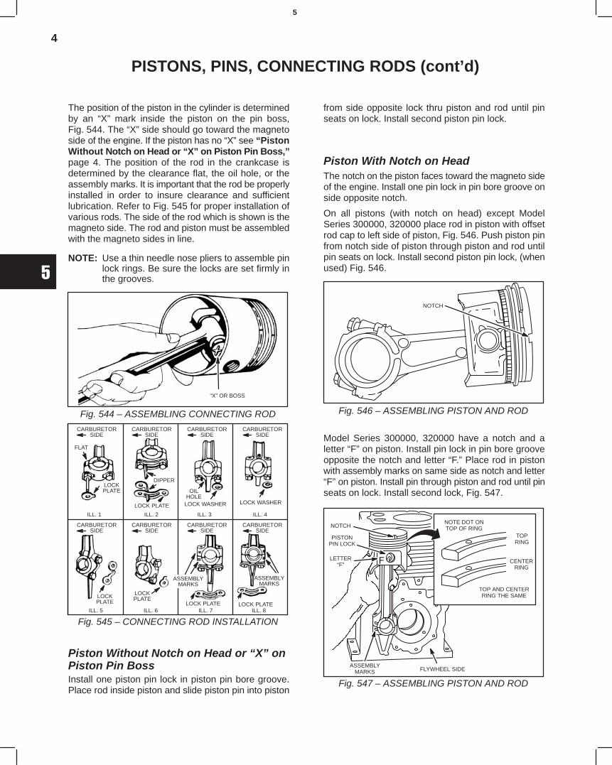
4
5
PISTONS, PINS, CONNECTING RODS (cont’d)
The position of the piston in the cylinder is determinedby an “X” mark inside the piston on the pin boss,Fig. 544. The “X” side should go toward the magnetoside of the engine. If the piston has no “X” see “PistonWithout Notch on Head or “X” on Piston Pin Boss,”page 4. The position of the rod in the crankcase isdetermined by the clearance flat, the oil hole, or theassembly marks. It is important that the rod be properlyinstalled in order to insure clearance and sufficientlubrication. Refer to Fig. 545 for proper installation ofvarious rods. The side of the rod which is shown is themagneto side. The rod and piston must be assembledwith the magneto sides in line.
NOTE: Use a thin needle nose pliers to assemble pinlock rings. Be sure the locks are set firmly inthe grooves.
Fig. 544 – ASSEMBLING CONNECTING ROD
“X” OR BOSS
Fig. 545 – CONNECTING ROD INSTALLATION
CARBURETORSIDE
CARBURETORSIDE
CARBURETORSIDE
CARBURETORSIDE
FLAT
LOCKPLATE
DIPPER
OILHOLE
LOCK WASHERLOCK PLATE LOCK WASHER
LOCKPLATE
LOCKPLATE
LOCK PLATE LOCK PLATE
ASSEMBLYMARKS
CARBURETORSIDE
CARBURETORSIDE
CARBURETORSIDE
CARBURETORSIDE
ASSEMBLYMARKS
ILL. 1 ILL. 2 ILL. 3 ILL. 4
ILL. 5 ILL. 6 ILL. 7 ILL. 8
Piston Without Notch on Head or “X” onPiston Pin Boss Install one piston pin lock in piston pin bore groove.Place rod inside piston and slide piston pin into piston
from side opposite lock thru piston and rod until pinseats on lock. Install second piston pin lock.
Piston With Notch on HeadThe notch on the piston faces toward the magneto sideof the engine. Install one pin lock in pin bore groove onside opposite notch.
On all pistons (with notch on head) except ModelSeries 300000, 320000 place rod in piston with offsetrod cap to left side of piston, Fig. 546. Push piston pinfrom notch side of piston through piston and rod untilpin seats on lock. Install second piston pin lock, (whenused) Fig. 546.
NOTCH
Fig. 546 – ASSEMBLING PISTON AND ROD
Model Series 300000, 320000 have a notch and aletter “F” on piston. Install pin lock in pin bore grooveopposite the notch and letter “F.” Place rod in pistonwith assembly marks on same side as notch and letter“F” on piston. Install pin through piston and rod until pinseats on lock. Install second lock, Fig. 547.
PISTONPIN LOCK
LETTER“F”
NOTCH
FLYWHEEL SIDE
NOTE DOT ONTOP OF RING
TOPRING
CENTERRING
TOP AND CENTERRING THE SAME
Fig. 547 – ASSEMBLING PISTON AND ROD
ASSEMBLYMARKS
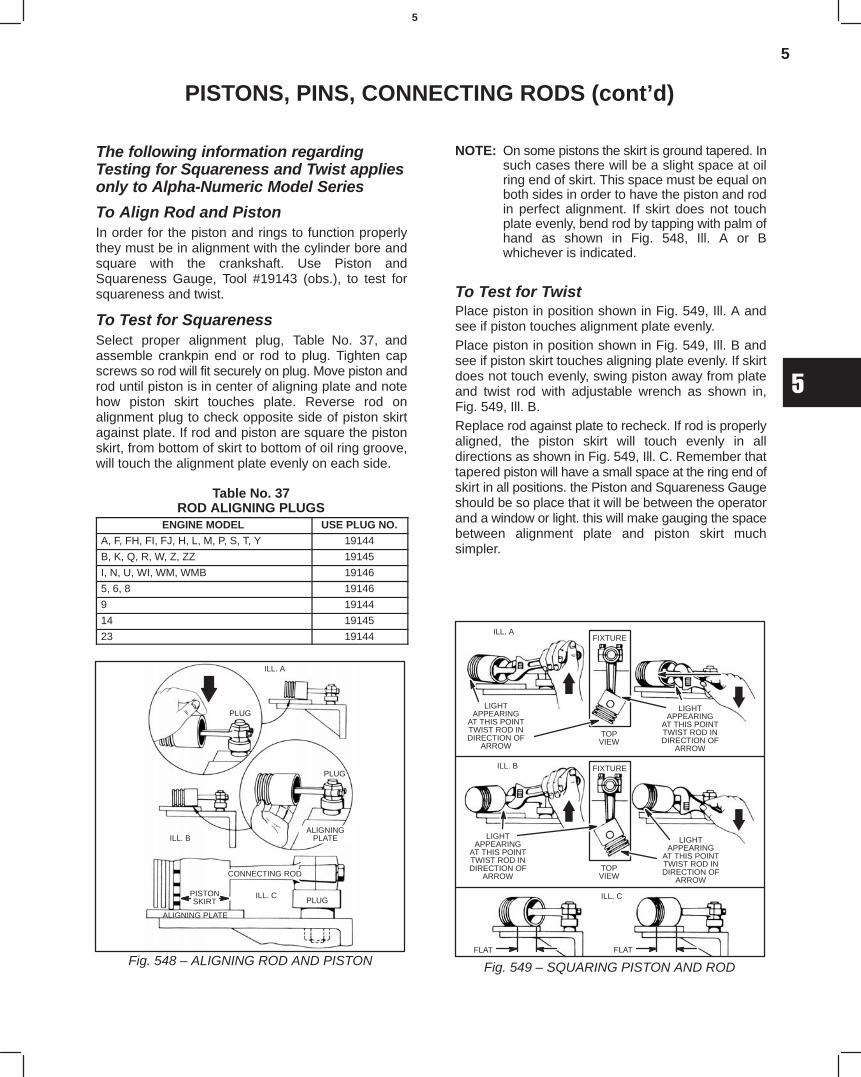
5
5
PISTONS, PINS, CONNECTING RODS (cont’d)
The following information regardingTesting for Squareness and Twist appliesonly to Alpha-Numeric Model Series
To Align Rod and PistonIn order for the piston and rings to function properlythey must be in alignment with the cylinder bore andsquare with the crankshaft. Use Piston andSquareness Gauge, Tool #19143 (obs.), to test forsquareness and twist.
To Test for SquarenessSelect proper alignment plug, Table No. 37, andassemble crankpin end or rod to plug. Tighten capscrews so rod will fit securely on plug. Move piston androd until piston is in center of aligning plate and notehow piston skirt touches plate. Reverse rod onalignment plug to check opposite side of piston skirtagainst plate. If rod and piston are square the pistonskirt, from bottom of skirt to bottom of oil ring groove,will touch the alignment plate evenly on each side.
Table No. 37ROD ALIGNING PLUGS
ENGINE MODEL USE PLUG NO.
A, F, FH, FI, FJ, H, L, M, P, S, T, Y 19144
B, K, Q, R, W, Z, ZZ 19145
I, N, U, WI, WM, WMB 19146
5, 6, 8 19146
9 19144
14 19145
23 19144
Fig. 548 – ALIGNING ROD AND PISTON
ILL. A
PLUG
PLUG
ALIGNINGPLATEILL. B
CONNECTING ROD
PLUGILL. CPISTON
SKIRT
ALIGNING PLATE
NOTE: On some pistons the skirt is ground tapered. Insuch cases there will be a slight space at oilring end of skirt. This space must be equal onboth sides in order to have the piston and rodin perfect alignment. If skirt does not touchplate evenly, bend rod by tapping with palm ofhand as shown in Fig. 548, Ill. A or Bwhichever is indicated.
To Test for TwistPlace piston in position shown in Fig. 549, Ill. A andsee if piston touches alignment plate evenly.Place piston in position shown in Fig. 549, Ill. B andsee if piston skirt touches aligning plate evenly. If skirtdoes not touch evenly, swing piston away from plateand twist rod with adjustable wrench as shown in,Fig. 549, Ill. B.Replace rod against plate to recheck. If rod is properlyaligned, the piston skirt will touch evenly in alldirections as shown in Fig. 549, Ill. C. Remember thattapered piston will have a small space at the ring end ofskirt in all positions. the Piston and Squareness Gaugeshould be so place that it will be between the operatorand a window or light. this will make gauging the spacebetween alignment plate and piston skirt muchsimpler.
Fig. 549 – SQUARING PISTON AND ROD
ILL. A
LIGHTAPPEARING
AT THIS POINTTWIST ROD INDIRECTION OF
ARROW
TOPVIEW
FIXTURE
LIGHTAPPEARING
AT THIS POINTTWIST ROD INDIRECTION OF
ARROW
ILL. B
LIGHTAPPEARING
AT THIS POINTTWIST ROD INDIRECTION OF
ARROW
LIGHTAPPEARING
AT THIS POINTTWIST ROD INDIRECTION OF
ARROW
FLAT
ILL. C
TOPVIEW
FIXTURE
FLAT
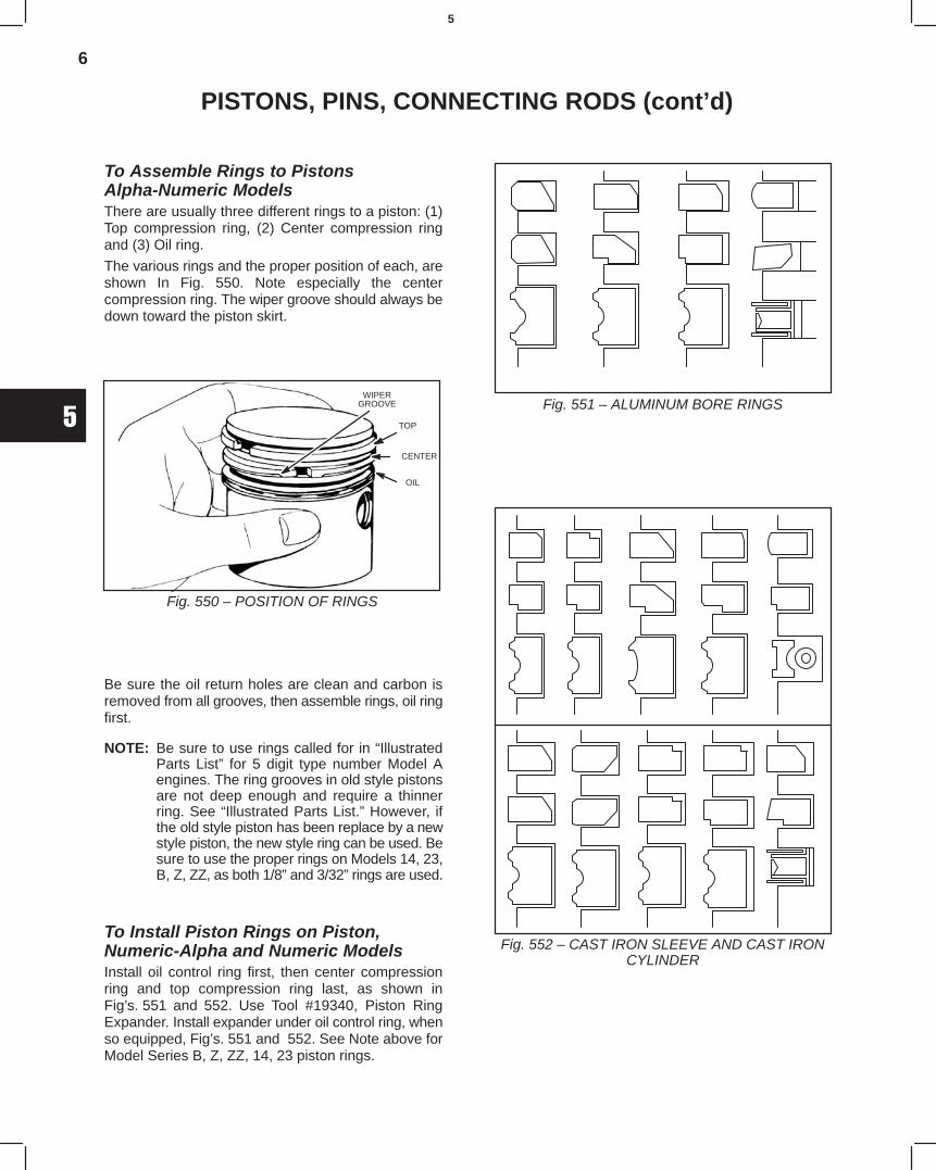
6
5
PISTONS, PINS, CONNECTING RODS (cont’d)
To Assemble Rings to PistonsAlpha-Numeric ModelsThere are usually three different rings to a piston: (1)Top compression ring, (2) Center compression ringand (3) Oil ring.
The various rings and the proper position of each, areshown In Fig. 550. Note especially the centercompression ring. The wiper groove should always bedown toward the piston skirt.
Fig. 550 – POSITION OF RINGS
WIPERGROOVE
TOP
CENTER
OIL
Be sure the oil return holes are clean and carbon isremoved from all grooves, then assemble rings, oil ringfirst.
NOTE: Be sure to use rings called for in “IllustratedParts List” for 5 digit type number Model Aengines. The ring grooves in old style pistonsare not deep enough and require a thinnerring. See “Illustrated Parts List.” However, ifthe old style piston has been replace by a newstyle piston, the new style ring can be used. Besure to use the proper rings on Models 14, 23,B, Z, ZZ, as both 1/8” and 3/32” rings are used.
To Install Piston Rings on Piston,Numeric-Alpha and Numeric ModelsInstall oil control ring first, then center compressionring and top compression ring last, as shown inFig’s. 551 and 552. Use Tool #19340, Piston RingExpander. Install expander under oil control ring, whenso equipped, Fig’s. 551 and 552. See Note above forModel Series B, Z, ZZ, 14, 23 piston rings.
Fig. 551 – ALUMINUM BORE RINGS
Fig. 552 – CAST IRON SLEEVE AND CAST IRONCYLINDER
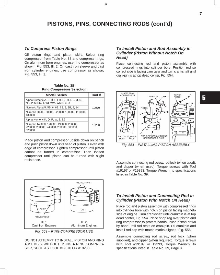
7
5
PISTONS, PINS, CONNECTING RODS (cont’d)
To Compress Piston RingsOil piston rings and piston skirt. Select ringcompressor from Table No. 38 and compress rings.On aluminum bore engines, use ring compressor asshown, Fig. 553, Ill. 2. On cast iron sleeve and castiron cylinder engines, use compressor as shown,Fig. 553, Ill. 1.
Table No. 38Ring Compressor Selection
Model Series Tool #Alpha Numeric A, B, D, F, FH, FJ, H, I, L, M, N,NS, P, S, SD, T, WI, WM, WMB, Y, U
Numeric Alpha 5, 5S, 6, 6B, 6S, 8, 8B, 9, 14 19070
Numeric 60000, 80000, 920000, 100000, 110000,130000
19070
Alpha Numeric K, Q, R, W, Z, ZZ
Numeric 140000, 170000, 190000, 200000,220000, 230000, 240000, 250000, 300000,320000
19230
Place piston and compressor upside down on benchand push piston down until head of piston is even withedge of compressor. Tighten compressor until pistoncannot be turned in compressor. Then loosencompressor until piston can be turned with slightresistance.
Fig. 553 – RING COMPRESSOR USE
PROJECTIONS
TOP
SKIRT SKIRT
PROJECTIONS
TOP
Ill. 1Cast Iron Engines
Ill. 2Aluminum Engines
DO NOT ATTEMPT TO INSTALL PISTON AND RINGASSEMBLY WITHOUT USING A RING COMPRES-SOR, SUCH AS TOOL #19070 OR #19230.
To Install Piston and Rod Assembly inCylinder (Piston Without Notch OnHead)Place connecting rod and piston assembly withcompressed rings into cylinder bore. Position rod socorrect side is facing cam gear and turn crankshaft untilcrankpin is at top dead center, Fig. 554.
Fig. 554 – INSTALLING PISTON ASSEMBLY
#19070 RINGCOMPRESSOR
PISTONSKIRT
SQUAREHOLE
WRENCH
PISTON
TOP OF PISTON AND RINGCOMPRESSOR FLUSH
TOP OFPISTON
Assemble connecting rod screw, rod lock (when used),and dipper (when used). Torque screws with Tool#19197 or #19393, Torque Wrench, to specificationslisted in Table No. 39.
To Install Piston and Connecting Rod inCylinder (Piston With Notch On Head)Place rod and piston assembly with compressed ringsinto cylinder bore with notch on piston facing magnetoside of engine. Turn crankshaft until crankpin is at topdead center, Fig. 554. Place shop rag over piston andring compressor to protect hands. Push piston downby hand until rod rests on crankpin. Oil crankpin andinstall rod cap with match marks aligned, Fig. 556.
Assemble connecting rod screw, rod lock (whensupplied), and dipper (when required). Torque screwswith Tool #19197 or 19393, Torque Wrench, tospecifications listed in Table No. 39, Page 8.
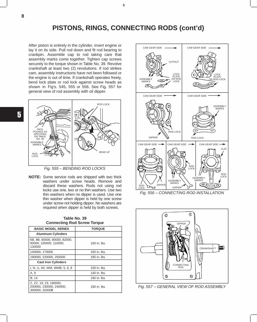
8
5
PISTONS, RINGS, CONNECTING RODS (cont’d)
After piston is entirely in the cylinder, invert engine orlay it on its side. Pull rod down and fit rod bearing tocrankpin. Assemble cap to rod taking care thatassembly marks come together. Tighten cap screwssecurely to the torque shown in Table No. 39. Revolvecrankshaft at least two (2) revolutions. If rod strikescam, assembly instructions have not been followed orthe engine is out of time. If crankshaft operates freely,bend lock plate or rod lock against screw heads asshown in Fig’s. 545, 555 or 556. See Fig. 557 forgeneral view of rod assembly with oil dipper.
Fig. 555 – BENDING ROD LOCKS
INCHPOUNDS ASSPECIFIEDON TABLE
NO. 39ASSEMBLE
MARKS
RODLOCK
ÁÁÁÁÁÁ
BEND UP
ROD LOCK
NOTE: Some service rods are shipped with two thickwashers under screw heads. Remove anddiscard these washers. Rods not using rodlocks use one, two or no thin washers. Use twothin washers when no dipper is used. Use onethin washer when dipper is held by one screwunder screw not holding dipper. No washers arerequired when dipper is held by both screws.
Table No. 39Connecting Rod Screw Torque
BASIC MODEL SERIES TORQUE
Aluminum Cylinders
6B, 8B, 60000, 80000, 82000,90000, 100000, 110000,130000
100 in. lbs.
140000, 170000 165 in. lbs.
190000, 220000, 250000 185 in. lbs.
Cast Iron Cylinders
I, N, U, WI, WM, WMB, 5, 6, 8 100 in. lbs.
A, 9 140 in. lbs.
B, 14 190 in. lbs.
Z, ZZ, 19, 23, 190000,200000, 230000, 240000,300000, 320000
190 in. lbs.
Fig. 556 – CONNECTING ROD INSTALLATION
CAM GEAR SIDE
CUTOUT
LOCKPLATE
OR RODLOCK
ASSEMBLYMARKS
CAM GEAR SIDE
LOCKPLATE
OR ROD LOCK
CAM GEAR SIDE CAM GEAR SIDE
ASSEMBLYMARKS
ROD LOCK
ROD LOCK
DIPPER
CAM GEAR SIDE CAM GEAR SIDE CAM GEAR SIDE
FLAT
RODLOCKASSEMBLY
MARKS
RODLOCK
ASSEMBLYMARKS
DIPPERDIPPERROD
LOCK
Fig. 557 – GENERAL VIEW OF ROD ASSEMBLY
CONNECTINGROD
CRANKSHAFT
DIPPER
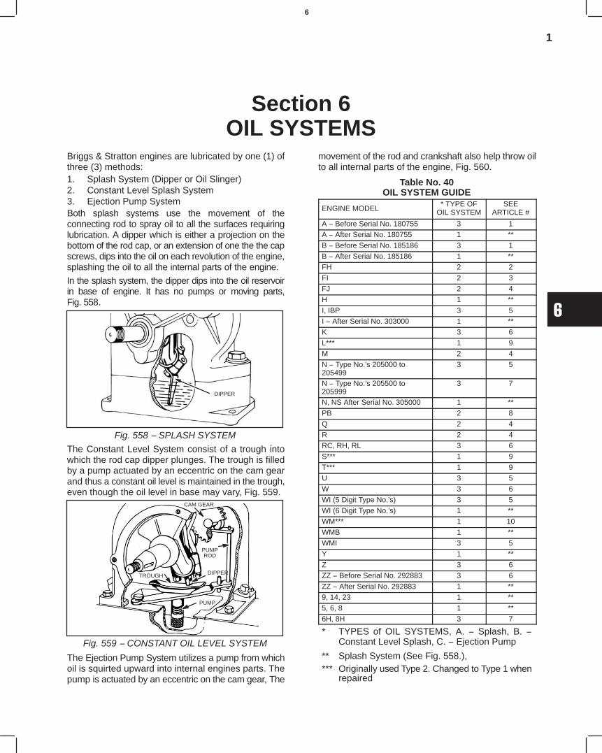
1
6
Section 6OIL SYSTEMS
Briggs & Stratton engines are lubricated by one (1) ofthree (3) methods:1. Splash System (Dipper or Oil Slinger)2. Constant Level Splash System3. Ejection Pump SystemBoth splash systems use the movement of theconnecting rod to spray oil to all the surfaces requiringlubrication. A dipper which is either a projection on thebottom of the rod cap, or an extension of one the the capscrews, dips into the oil on each revolution of the engine,splashing the oil to all the internal parts of the engine.
In the splash system, the dipper dips into the oil reservoirin base of engine. It has no pumps or moving parts,Fig. 558.
Fig. 558 − SPLASH SYSTEM
DIPPER
The Constant Level System consist of a trough intowhich the rod cap dipper plunges. The trough is filledby a pump actuated by an eccentric on the cam gearand thus a constant oil level is maintained in the trough,even though the oil level in base may vary, Fig. 559.
Fig. 559 − CONSTANT OIL LEVEL SYSTEM
TROUGH
CAM GEAR
PUMPROD
DIPPER
PUMP
The Ejection Pump System utilizes a pump from whichoil is squirted upward into internal engines parts. Thepump is actuated by an eccentric on the cam gear, The
movement of the rod and crankshaft also help throw oilto all internal parts of the engine, Fig. 560.
Table No. 40OIL SYSTEM GUIDE
ENGINE MODEL* TYPE OF
OIL SYSTEMSEE
ARTICLE #
A − Before Serial No. 180755 3 1
A − After Serial No. 180755 1 **
B − Before Serial No. 185186 3 1
B − After Serial No. 185186 1 **
FH 2 2
FI 2 3
FJ 2 4
H 1 **
I, IBP 3 5
I − After Serial No. 303000 1 **
K 3 6
L*** 1 9
M 2 4
N − Type No.’s 205000 to205499
3 5
N − Type No.’s 205500 to205999
3 7
N, NS After Serial No. 305000 1 **
PB 2 8
Q 2 4
R 2 4
RC, RH, RL 3 6
S*** 1 9
T*** 1 9
U 3 5
W 3 6
WI (5 Digit Type No.’s) 3 5
WI (6 Digit Type No.’s) 1 **
WM*** 1 10
WMB 1 **
WMI 3 5
Y 1 **
Z 3 6
ZZ − Before Serial No. 292883 3 6
ZZ − After Serial No. 292883 1 **
9, 14, 23 1 **
5, 6, 8 1 **
6H, 8H 3 7
* TYPES of OIL SYSTEMS, A. − Splash, B. −Constant Level Splash, C. − Ejection Pump
** Splash System (See Fig. 558.),*** Originally used Type 2. Changed to Type 1 when
repaired
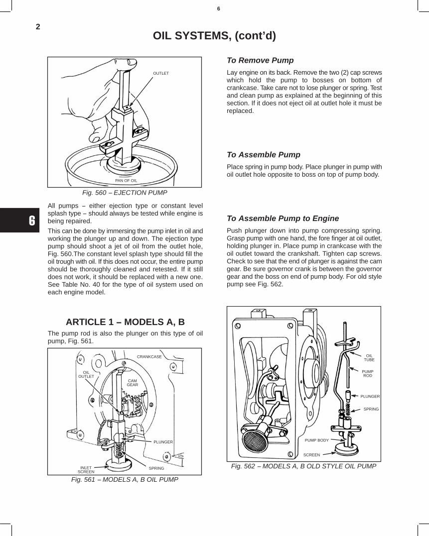
2
6
OIL SYSTEMS, (cont’d)
Fig. 560 − EJECTION PUMP
OUTLET
PAN OF OIL
All pumps − either ejection type or constant levelsplash type − should always be tested while engine isbeing repaired.
This can be done by immersing the pump inlet in oil andworking the plunger up and down. The ejection typepump should shoot a jet of oil from the outlet hole,Fig. 560.The constant level splash type should fill theoil trough with oil. If this does not occur, the entire pumpshould be thoroughly cleaned and retested. If it stilldoes not work, it should be replaced with a new one.See Table No. 40 for the type of oil system used oneach engine model.
ARTICLE 1 − MODELS A, BThe pump rod is also the plunger on this type of oilpump, Fig. 561.
Fig. 561 − MODELS A, B OIL PUMP
CRANKCASE
CAMGEAR
OILOUTLET
PLUNGER
SPRINGINLETSCREEN
To Remove PumpLay engine on its back. Remove the two (2) cap screwswhich hold the pump to bosses on bottom ofcrankcase. Take care not to lose plunger or spring. Testand clean pump as explained at the beginning of thissection. If it does not eject oil at outlet hole it must bereplaced.
To Assemble PumpPlace spring in pump body. Place plunger in pump withoil outlet hole opposite to boss on top of pump body.
To Assemble Pump to EnginePush plunger down into pump compressing spring.Grasp pump with one hand, the fore finger at oil outlet,holding plunger in. Place pump in crankcase with theoil outlet toward the crankshaft. Tighten cap screws.Check to see that the end of plunger is against the camgear. Be sure governor crank is between the governorgear and the boss on end of pump body. For old stylepump see Fig. 562.
Fig. 562 − MODELS A, B OLD STYLE OIL PUMP
SCREEN
PUMP BODY
SPRING
PLUNGER
PUMPROD
OILTUBE
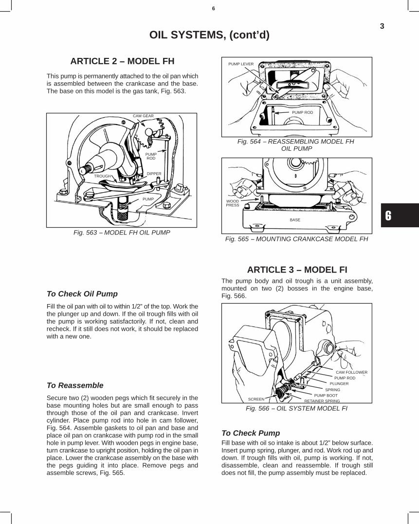
3
6
OIL SYSTEMS, (cont’d)
ARTICLE 2 − MODEL FH
This pump is permanently attached to the oil pan whichis assembled between the crankcase and the base.The base on this model is the gas tank, Fig. 563.
TROUGH
CAM GEAR
PUMPROD
DIPPER
PUMP
Fig. 563 − MODEL FH OIL PUMP
To Check Oil Pump
Fill the oil pan with oil to within 1/2” of the top. Work thethe plunger up and down. If the oil trough fills with oilthe pump is working satisfactorily. If not, clean andrecheck. If it still does not work, it should be replacedwith a new one.
To Reassemble
Secure two (2) wooden pegs which fit securely in thebase mounting holes but are small enough to passthrough those of the oil pan and crankcase. Invertcylinder. Place pump rod into hole in cam follower,Fig. 564. Assemble gaskets to oil pan and base andplace oil pan on crankcase with pump rod in the smallhole in pump lever. With wooden pegs in engine base,turn crankcase to upright position, holding the oil pan inplace. Lower the crankcase assembly on the base withthe pegs guiding it into place. Remove pegs andassemble screws, Fig. 565.
Fig. 564 − REASSEMBLING MODEL FH OIL PUMP
PUMP ROD
PUMP LEVER
Fig. 565 − MOUNTING CRANKCASE MODEL FH
WOODPRESS
BASE
ARTICLE 3 − MODEL FIThe pump body and oil trough is a unit assembly,mounted on two (2) bosses in the engine base,Fig. 566.
Fig. 566 − OIL SYSTEM MODEL FI
CAM FOLLOWER
PUMP ROD
PLUNGER
SPRING
PUMP BOOTSCREEN RETAINER SPRING
To Check PumpFill base with oil so intake is about 1/2” below surface.Insert pump spring, plunger, and rod. Work rod up anddown. If trough fills with oil, pump is working. If not,disassemble, clean and reassemble. If trough stilldoes not fill, the pump assembly must be replaced.
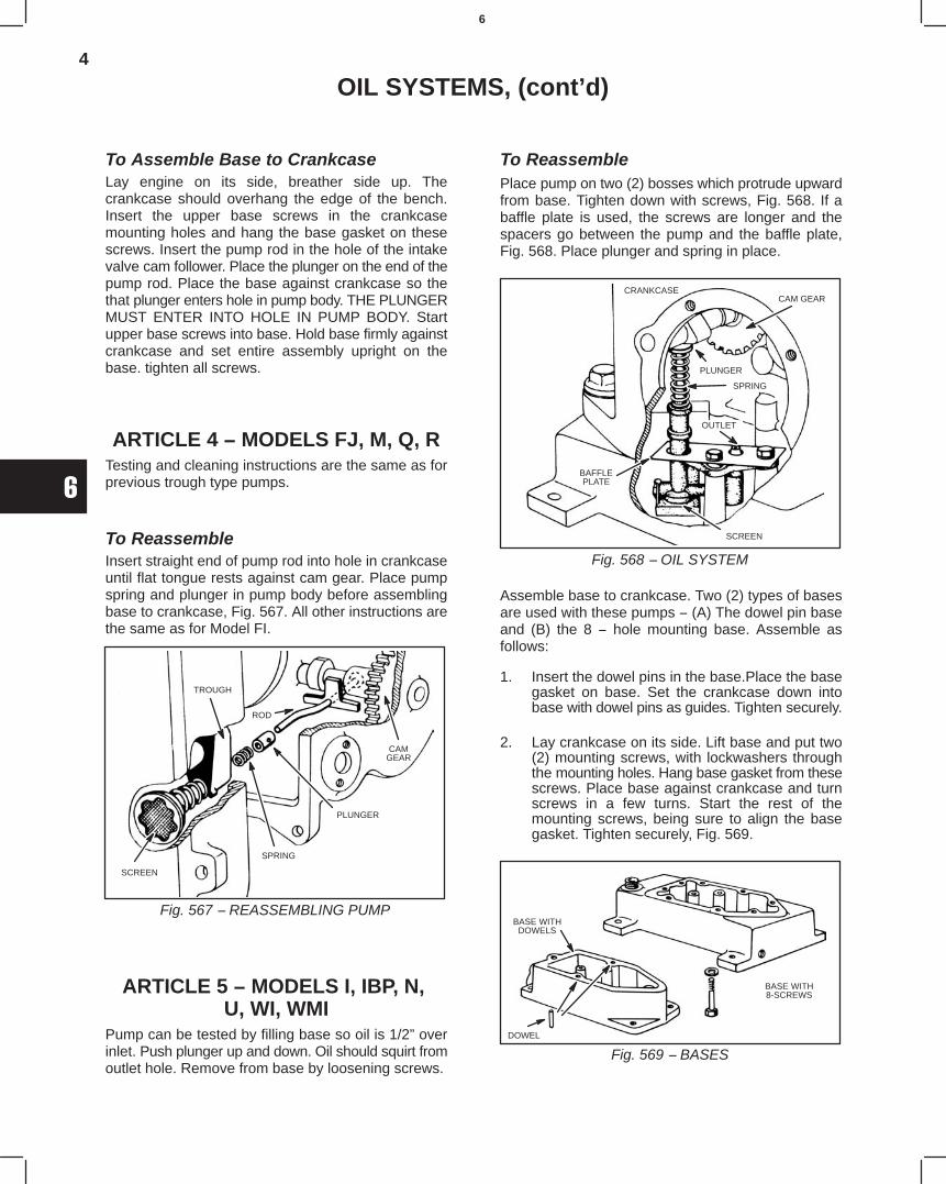
4
6
OIL SYSTEMS, (cont’d)
To Assemble Base to CrankcaseLay engine on its side, breather side up. Thecrankcase should overhang the edge of the bench.Insert the upper base screws in the crankcasemounting holes and hang the base gasket on thesescrews. Insert the pump rod in the hole of the intakevalve cam follower. Place the plunger on the end of thepump rod. Place the base against crankcase so thethat plunger enters hole in pump body. THE PLUNGERMUST ENTER INTO HOLE IN PUMP BODY. Startupper base screws into base. Hold base firmly againstcrankcase and set entire assembly upright on thebase. tighten all screws.
ARTICLE 4 − MODELS FJ, M, Q, RTesting and cleaning instructions are the same as forprevious trough type pumps.
To ReassembleInsert straight end of pump rod into hole in crankcaseuntil flat tongue rests against cam gear. Place pumpspring and plunger in pump body before assemblingbase to crankcase, Fig. 567. All other instructions arethe same as for Model FI.
Fig. 567 − REASSEMBLING PUMP
SCREEN
TROUGH
ROD
PLUNGER
SPRING
CAMGEAR
ARTICLE 5 − MODELS I, IBP, N, U, WI, WMI
Pump can be tested by filling base so oil is 1/2” overinlet. Push plunger up and down. Oil should squirt fromoutlet hole. Remove from base by loosening screws.
To ReassemblePlace pump on two (2) bosses which protrude upwardfrom base. Tighten down with screws, Fig. 568. If abaffle plate is used, the screws are longer and thespacers go between the pump and the baffle plate,Fig. 568. Place plunger and spring in place.
Fig. 568 − OIL SYSTEM
CAM GEARCRANKCASE
PLUNGER
BAFFLEPLATE
SPRING
OUTLET
SCREEN
Assemble base to crankcase. Two (2) types of basesare used with these pumps − (A) The dowel pin baseand (B) the 8 − hole mounting base. Assemble asfollows:
1. Insert the dowel pins in the base.Place the basegasket on base. Set the crankcase down intobase with dowel pins as guides. Tighten securely.
2. Lay crankcase on its side. Lift base and put two(2) mounting screws, with lockwashers throughthe mounting holes. Hang base gasket from thesescrews. Place base against crankcase and turnscrews in a few turns. Start the rest of themounting screws, being sure to align the basegasket. Tighten securely, Fig. 569.
Fig. 569 − BASES
BASE WITHDOWELS
DOWEL
BASE WITH8-SCREWS
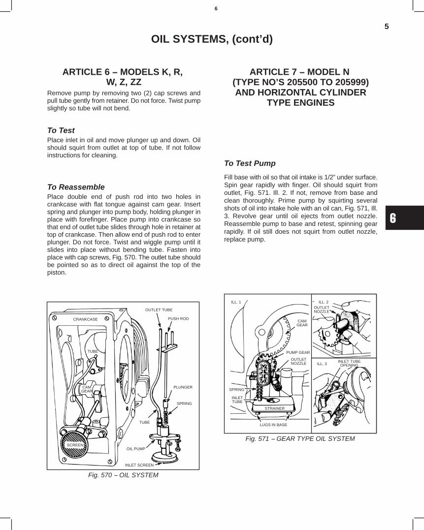
5
6
OIL SYSTEMS, (cont’d)
ARTICLE 6 − MODELS K, R, W, Z, ZZ
Remove pump by removing two (2) cap screws andpull tube gently from retainer. Do not force. Twist pumpslightly so tube will not bend.
To TestPlace inlet in oil and move plunger up and down. Oilshould squirt from outlet at top of tube. If not followinstructions for cleaning.
To ReassemblePlace double end of push rod into two holes incrankcase with flat tongue against cam gear. Insertspring and plunger into pump body, holding plunger inplace with forefinger. Place pump into crankcase sothat end of outlet tube slides through hole in retainer attop of crankcase. Then allow end of push rod to enterplunger. Do not force. Twist and wiggle pump until itslides into place without bending tube. Fasten intoplace with cap screws, Fig. 570. The outlet tube shouldbe pointed so as to direct oil against the top of thepiston.
Fig. 570 − OIL SYSTEM
CRANKCASE
OUTLET TUBE
PUSH ROD
PLUNGER
SPRING
TUBE
OIL PUMP
INLET SCREEN
SCREEN
CAMGEAR
TUBE
ARTICLE 7 − MODEL N (TYPE NO’S 205500 TO 205999)AND HORIZONTAL CYLINDER
TYPE ENGINES
To Test Pump
Fill base with oil so that oil intake is 1/2” under surface.Spin gear rapidly with finger. Oil should squirt fromoutlet, Fig. 571. Ill. 2. If not, remove from base andclean thoroughly. Prime pump by squirting severalshots of oil into intake hole with an oil can, Fig. 571, Ill.3. Revolve gear until oil ejects from outlet nozzle.Reassemble pump to base and retest, spinning gearrapidly. If oil still does not squirt from outlet nozzle,replace pump.
Fig. 571 − GEAR TYPE OIL SYSTEM
CAMGEAR
PUMP GEAR
OUTLETNOZZLE
SPRING
INLETTUBE
STRAINER
LUGS IN BASE
OUTLETNOZZLE
ILL. 3
ILL. 1 ILL. 2
INLET TUBEOPENING
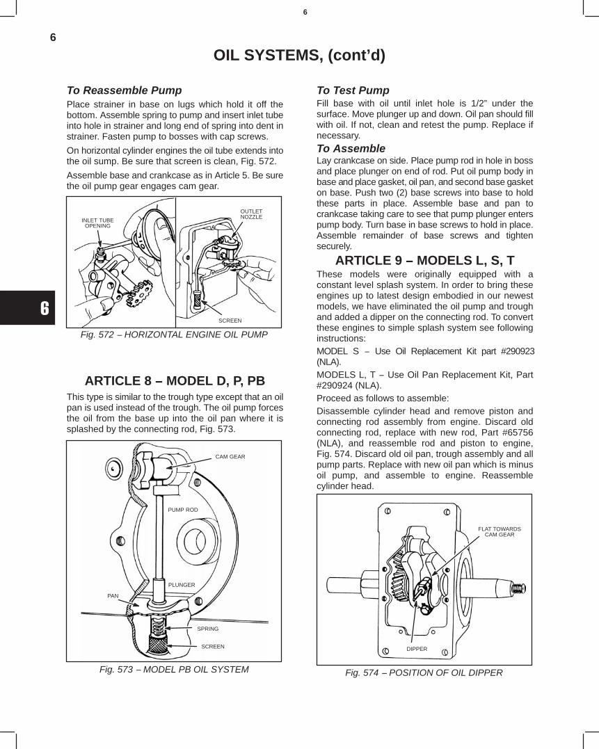
6
6
OIL SYSTEMS, (cont’d)
To Reassemble PumpPlace strainer in base on lugs which hold it off thebottom. Assemble spring to pump and insert inlet tubeinto hole in strainer and long end of spring into dent instrainer. Fasten pump to bosses with cap screws.
On horizontal cylinder engines the oil tube extends intothe oil sump. Be sure that screen is clean, Fig. 572.
Assemble base and crankcase as in Article 5. Be surethe oil pump gear engages cam gear.
Fig. 572 − HORIZONTAL ENGINE OIL PUMP
INLET TUBEOPENING
OUTLETNOZZLE
SCREEN
ARTICLE 8 − MODEL D, P, PBThis type is similar to the trough type except that an oilpan is used instead of the trough. The oil pump forcesthe oil from the base up into the oil pan where it issplashed by the connecting rod, Fig. 573.
Fig. 573 − MODEL PB OIL SYSTEM
CAM GEAR
PUMP ROD
PLUNGER
PAN
SPRING
SCREEN
To Test PumpFill base with oil until inlet hole is 1/2” under thesurface. Move plunger up and down. Oil pan should fillwith oil. If not, clean and retest the pump. Replace ifnecessary.
To AssembleLay crankcase on side. Place pump rod in hole in bossand place plunger on end of rod. Put oil pump body inbase and place gasket, oil pan, and second base gasketon base. Push two (2) base screws into base to holdthese parts in place. Assemble base and pan tocrankcase taking care to see that pump plunger enterspump body. Turn base in base screws to hold in place.Assemble remainder of base screws and tightensecurely.
ARTICLE 9 − MODELS L, S, TThese models were originally equipped with aconstant level splash system. In order to bring theseengines up to latest design embodied in our newestmodels, we have eliminated the oil pump and troughand added a dipper on the connecting rod. To convertthese engines to simple splash system see followinginstructions:MODEL S − Use Oil Replacement Kit part #290923(NLA).MODELS L, T − Use Oil Pan Replacement Kit, Part#290924 (NLA).Proceed as follows to assemble:Disassemble cylinder head and remove piston andconnecting rod assembly from engine. Discard oldconnecting rod, replace with new rod, Part #65756(NLA), and reassemble rod and piston to engine,Fig. 574. Discard old oil pan, trough assembly and allpump parts. Replace with new oil pan which is minusoil pump, and assemble to engine. Reassemblecylinder head.
Fig. 574 − POSITION OF OIL DIPPER
FLAT TOWARDSCAM GEAR
DIPPER
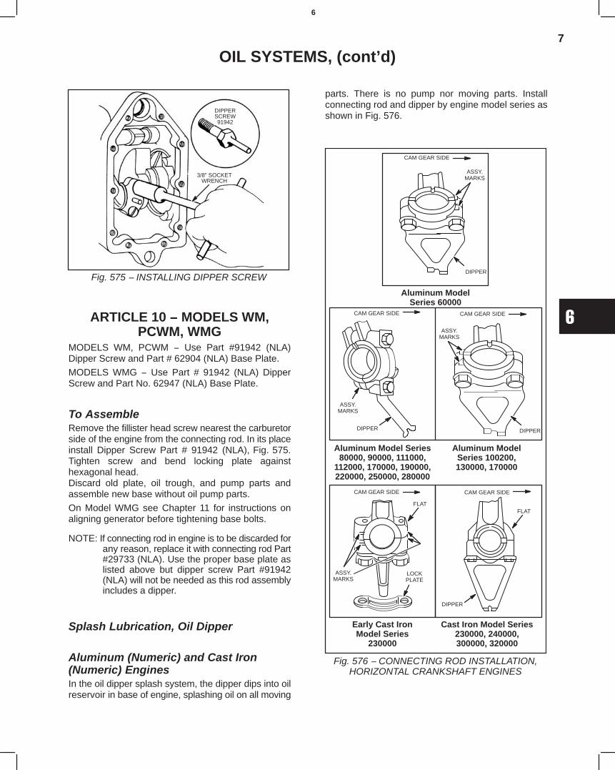
7
6
OIL SYSTEMS, (cont’d)
Fig. 575 − INSTALLING DIPPER SCREW
DIPPERSCREW91942
3/8” SOCKETWRENCH
ARTICLE 10 − MODELS WM,PCWM, WMG
MODELS WM, PCWM − Use Part #91942 (NLA)Dipper Screw and Part # 62904 (NLA) Base Plate.
MODELS WMG − Use Part # 91942 (NLA) DipperScrew and Part No. 62947 (NLA) Base Plate.
To AssembleRemove the fillister head screw nearest the carburetorside of the engine from the connecting rod. In its placeinstall Dipper Screw Part # 91942 (NLA), Fig. 575.Tighten screw and bend locking plate againsthexagonal head.Discard old plate, oil trough, and pump parts andassemble new base without oil pump parts.
On Model WMG see Chapter 11 for instructions onaligning generator before tightening base bolts.
NOTE: If connecting rod in engine is to be discarded forany reason, replace it with connecting rod Part#29733 (NLA). Use the proper base plate aslisted above but dipper screw Part #91942(NLA) will not be needed as this rod assemblyincludes a dipper.
Splash Lubrication, Oil Dipper
Aluminum (Numeric) and Cast Iron(Numeric) EnginesIn the oil dipper splash system, the dipper dips into oilreservoir in base of engine, splashing oil on all moving
parts. There is no pump nor moving parts. Installconnecting rod and dipper by engine model series asshown in Fig. 576.
Early Cast IronModel Series
230000
Aluminum ModelSeries 60000
Aluminum Model Series80000, 90000, 111000,
112000, 170000, 190000,220000, 250000, 280000
Aluminum ModelSeries 100200,130000, 170000
Cast Iron Model Series230000, 240000,300000, 320000
Fig. 576 − CONNECTING ROD INSTALLATION,HORIZONTAL CRANKSHAFT ENGINES
CAM GEAR SIDE
DIPPER
ASSY.MARKS
CAM GEAR SIDE CAM GEAR SIDE
ASSY.MARKS
DIPPER DIPPER
ASSY.MARKS
ASSY.MARKS
FLAT
LOCKPLATE
CAM GEAR SIDE CAM GEAR SIDE
FLAT
DIPPER
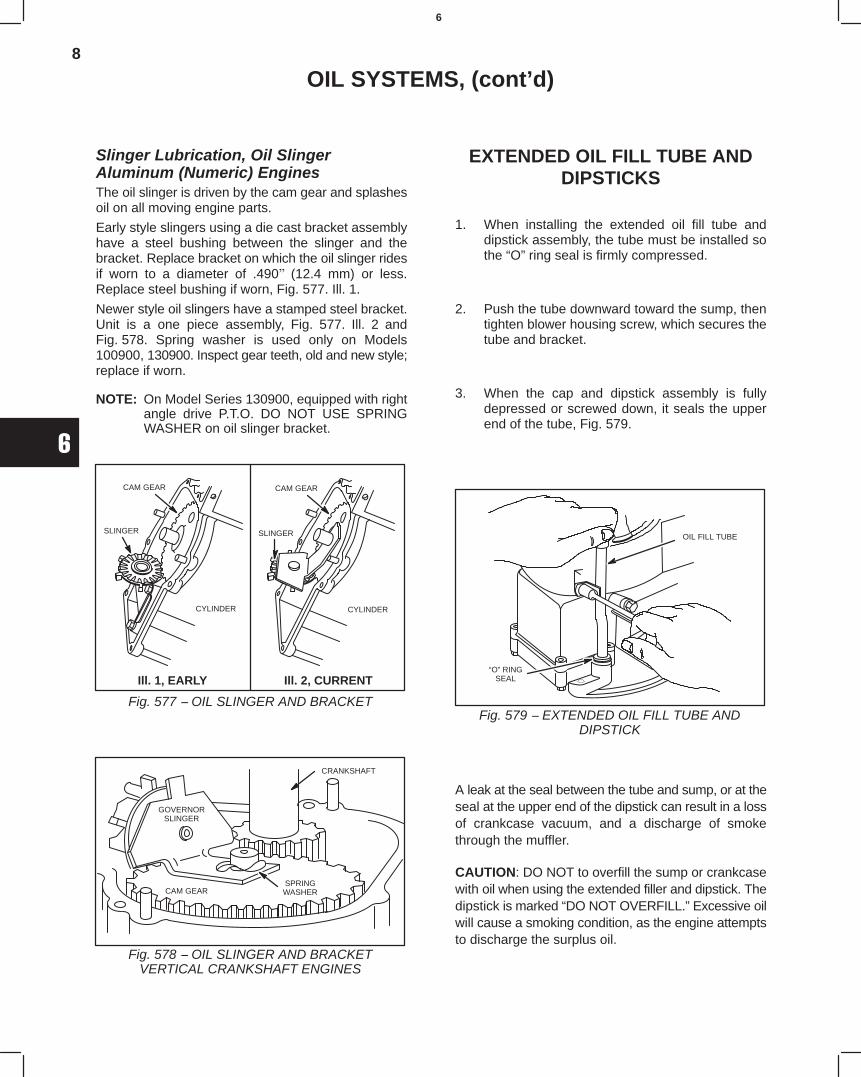
8
6
OIL SYSTEMS, (cont’d)
Slinger Lubrication, Oil SlingerAluminum (Numeric) EnginesThe oil slinger is driven by the cam gear and splashesoil on all moving engine parts.
Early style slingers using a die cast bracket assemblyhave a steel bushing between the slinger and thebracket. Replace bracket on which the oil slinger ridesif worn to a diameter of .490" (12.4 mm) or less.Replace steel bushing if worn, Fig. 577. Ill. 1.
Newer style oil slingers have a stamped steel bracket.Unit is a one piece assembly, Fig. 577. Ill. 2 andFig. 578. Spring washer is used only on Models100900, 130900. Inspect gear teeth, old and new style;replace if worn.
NOTE: On Model Series 130900, equipped with rightangle drive P.T.O. DO NOT USE SPRINGWASHER on oil slinger bracket.
CAM GEAR
SLINGER
CYLINDER
CAM GEAR
SLINGER
CYLINDER
Fig. 577 − OIL SLINGER AND BRACKET
Ill. 1, EARLY Ill. 2, CURRENT
CRANKSHAFT
SPRINGWASHERCAM GEAR
GOVERNORSLINGER
Fig. 578 − OIL SLINGER AND BRACKETVERTICAL CRANKSHAFT ENGINES
EXTENDED OIL FILL TUBE ANDDIPSTICKS
1. When installing the extended oil fill tube anddipstick assembly, the tube must be installed sothe “O” ring seal is firmly compressed.
2. Push the tube downward toward the sump, thentighten blower housing screw, which secures thetube and bracket.
3. When the cap and dipstick assembly is fullydepressed or screwed down, it seals the upperend of the tube, Fig. 579.
“O” RINGSEAL
OIL FILL TUBE
Fig. 579 − EXTENDED OIL FILL TUBE ANDDIPSTICK
A leak at the seal between the tube and sump, or at theseal at the upper end of the dipstick can result in a lossof crankcase vacuum, and a discharge of smokethrough the muffler.
CAUTION: DO NOT to overfill the sump or crankcasewith oil when using the extended filler and dipstick. Thedipstick is marked “DO NOT OVERFILL.” Excessive oilwill cause a smoking condition, as the engine attemptsto discharge the surplus oil.
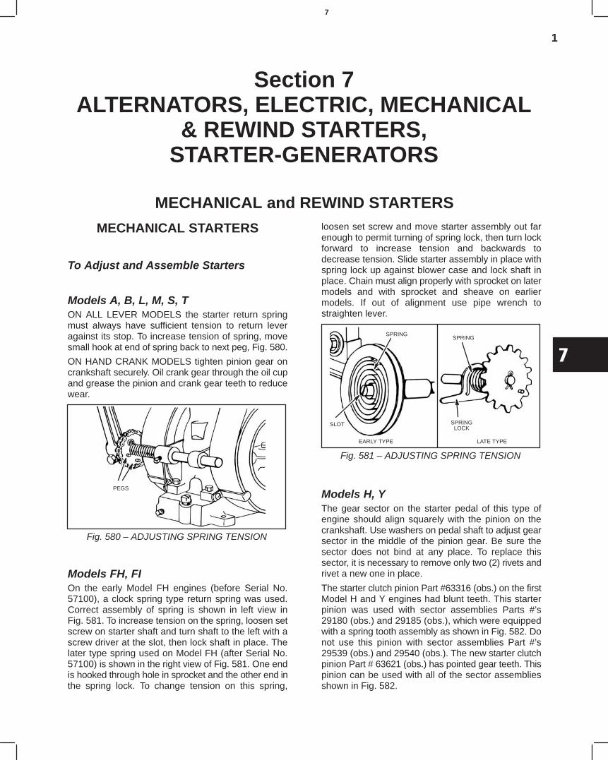
1
7
Section 7ALTERNATORS, ELECTRIC, MECHANICAL
& REWIND STARTERS,STARTER-GENERATORS
MECHANICAL and REWIND STARTERS
MECHANICAL STARTERS
To Adjust and Assemble Starters
Models A, B, L, M, S, TON ALL LEVER MODELS the starter return springmust always have sufficient tension to return leveragainst its stop. To increase tension of spring, movesmall hook at end of spring back to next peg, Fig. 580.
ON HAND CRANK MODELS tighten pinion gear oncrankshaft securely. Oil crank gear through the oil cupand grease the pinion and crank gear teeth to reducewear.
Fig. 580 – ADJUSTING SPRING TENSION
PEGS
Models FH, FIOn the early Model FH engines (before Serial No.57100), a clock spring type return spring was used.Correct assembly of spring is shown in left view inFig. 581. To increase tension on the spring, loosen setscrew on starter shaft and turn shaft to the left with ascrew driver at the slot, then lock shaft in place. Thelater type spring used on Model FH (after Serial No.57100) is shown in the right view of Fig. 581. One endis hooked through hole in sprocket and the other end inthe spring lock. To change tension on this spring,
loosen set screw and move starter assembly out farenough to permit turning of spring lock, then turn lockforward to increase tension and backwards todecrease tension. Slide starter assembly in place withspring lock up against blower case and lock shaft inplace. Chain must align properly with sprocket on latermodels and with sprocket and sheave on earliermodels. If out of alignment use pipe wrench tostraighten lever.
Fig. 581 – ADJUSTING SPRING TENSION
SPRING
SLOT
EARLY TYPE
SPRING
SPRINGLOCK
LATE TYPE
Models H, YThe gear sector on the starter pedal of this type ofengine should align squarely with the pinion on thecrankshaft. Use washers on pedal shaft to adjust gearsector in the middle of the pinion gear. Be sure thesector does not bind at any place. To replace thissector, it is necessary to remove only two (2) rivets andrivet a new one in place.
The starter clutch pinion Part #63316 (obs.) on the firstModel H and Y engines had blunt teeth. This starterpinion was used with sector assemblies Parts #’s29180 (obs.) and 29185 (obs.), which were equippedwith a spring tooth assembly as shown in Fig. 582. Donot use this pinion with sector assemblies Part #’s29539 (obs.) and 29540 (obs.). The new starter clutchpinion Part # 63621 (obs.) has pointed gear teeth. Thispinion can be used with all of the sector assembliesshown in Fig. 582.
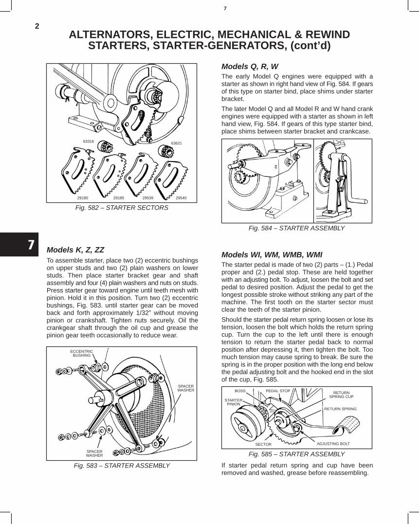
2
7
ALTERNATORS, ELECTRIC, MECHANICAL & REWINDSTARTERS, STARTER-GENERATORS, (cont’d)
Fig. 582 – STARTER SECTORS
63316
29180 29185 29539 29540
63621
Models K, Z, ZZTo assemble starter, place two (2) eccentric bushingson upper studs and two (2) plain washers on lowerstuds. Then place starter bracket gear and shaftassembly and four (4) plain washers and nuts on studs.Press starter gear toward engine until teeth mesh withpinion. Hold it in this position. Turn two (2) eccentricbushings, Fig. 583. until starter gear can be movedback and forth approximately 1/32” without movingpinion or crankshaft. Tighten nuts securely. Oil thecrankgear shaft through the oil cup and grease thepinion gear teeth occasionally to reduce wear.
Fig. 583 – STARTER ASSEMBLY
ECCENTRICBUSHING
SPACERWASHER
SPACERWASHER
Models Q, R, WThe early Model Q engines were equipped with astarter as shown in right hand view of Fig. 584. If gearsof this type on starter bind, place shims under starterbracket.
The later Model Q and all Model R and W hand crankengines were equipped with a starter as shown in lefthand view, Fig. 584. If gears of this type starter bind,place shims between starter bracket and crankcase.
Fig. 584 – STARTER ASSEMBLY
Models WI, WM, WMB, WMIThe starter pedal is made of two (2) parts – (1.) Pedalproper and (2.) pedal stop. These are held togetherwith an adjusting bolt. To adjust, loosen the bolt and setpedal to desired position. Adjust the pedal to get thelongest possible stroke without striking any part of themachine. The first tooth on the starter sector mustclear the teeth of the starter pinion.
Should the starter pedal return spring loosen or lose itstension, loosen the bolt which holds the return springcup. Turn the cup to the left until there is enoughtension to return the starter pedal back to normalposition after depressing it, then tighten the bolt. Toomuch tension may cause spring to break. Be sure thespring is in the proper position with the long end belowthe pedal adjusting bolt and the hooked end in the slotof the cup, Fig. 585.
Fig. 585 – STARTER ASSEMBLY
BOSS PEDAL STOP
STARTERPINION
RETURN SPRING
RETURNSPRING CUP
ADJUSTING BOLTSECTOR
If starter pedal return spring and cup have beenremoved and washed, grease before reassembling.
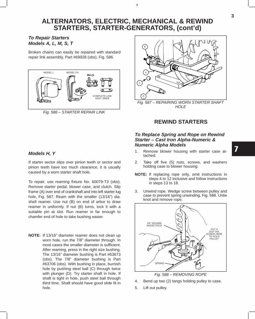
3
7
ALTERNATORS, ELECTRIC, MECHANICAL & REWINDSTARTERS, STARTER-GENERATORS, (cont’d)
To Repair StartersModels A, L, M, S, T
Broken chains can easily be repaired with standardrepair link assembly, Part #69928 (obs), Fig. 586.
Fig. 586 – STARTER REPAIR LINK
MODEL L MODEL FH
COMPLETE LINKASSY. 69928
Models H, Y
If starter sector slips over pinion teeth or sector andpinion teeth have too much clearance, it is usuallycaused by a worn starter shaft hole.
To repair, use reaming fixture No. 60079-T3 (obs).Remove starter pedal, blower case, and clutch. Slipframe (A) over end of crankshaft and into left starter lughole, Fig. 587. Ream with the smaller (13/16”) dia.shell reamer. Use nut (B) on end of arbor to drawreamer in uniformly. If nut (B) turns, lock it with asuitable pin at slot. Run reamer in far enough tochamfer end of hole to take bushing easier.
NOTE: If 13/16” diameter reamer does not clean upworn hole, run the 7/8” diameter through. Inmost cases the smaller diameter is sufficient.After reaming, press in the right size bushing.The 13/16” diameter bushing is Part #63673(obs). The 7/8” diameter bushing is Part#63706 (obs). With bushing in place, burnishhole by pushing steel ball (C) through twicewith plunger (D). Try starter shaft in hole. Ifshaft is tight in hole, push steel ball throughthird time. Shaft should have good slide fit inhole.
Fig. 587 – REPAIRING WORN STARTER SHAFTHOLE
B
A
C
D
REWIND STARTERS
To Replace Spring and Rope on RewindStarter – Cast Iron Alpha-Numeric &Numeric Alpha Models1. Remove blower housing with starter case at-
tached.
2. Take off five (5) nuts, screws, and washersholding case to blower housing.
NOTE: If replacing rope only, omit instructions insteps 4 to 12 inclusive and follow instructionsin steps 13 to 18.
3. Unwind rope. Wedge screw between pulley andcase to prevent spring unwinding, Fig. 588. Untieknot and remove rope.
Fig. 588 – REMOVING ROPE
3/4” SQUAREWOOD STICK
PUT A3/16” DIA.
SCREW HERETO HOLDPULLEY
SPRING
4. Bend up two (2) tangs holding pulley to case.
5. Lift out pulley.
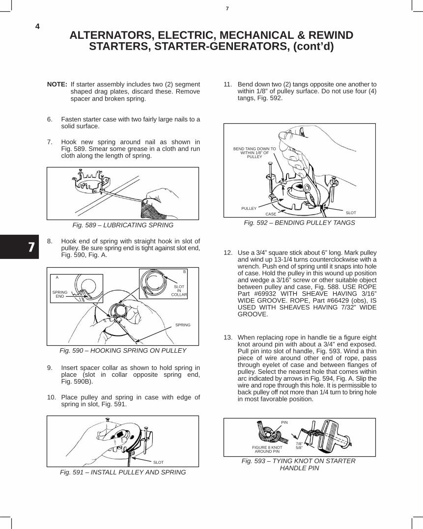
4
7
ALTERNATORS, ELECTRIC, MECHANICAL & REWINDSTARTERS, STARTER-GENERATORS, (cont’d)
NOTE: If starter assembly includes two (2) segmentshaped drag plates, discard these. Removespacer and broken spring.
6. Fasten starter case with two fairly large nails to asolid surface.
7. Hook new spring around nail as shown inFig. 589. Smear some grease in a cloth and runcloth along the length of spring.
Fig. 589 – LUBRICATING SPRING
8. Hook end of spring with straight hook in slot ofpulley. Be sure spring end is tight against slot end,Fig. 590, Fig. A.
Fig. 590 – HOOKING SPRING ON PULLEY
SLOTIN
COLLAR
B
A
SPRINGEND
SPRING
9. Insert spacer collar as shown to hold spring inplace (slot in collar opposite spring end,Fig. 590B).
10. Place pulley and spring in case with edge ofspring in slot, Fig. 591.
Fig. 591 – INSTALL PULLEY AND SPRING
SLOT
11. Bend down two (2) tangs opposite one another towithin 1/8” of pulley surface. Do not use four (4)tangs, Fig. 592.
Fig. 592 – BENDING PULLEY TANGS
BEND TANG DOWN TOWITHIN 1/8” OF
PULLEY
CASE SLOTPULLEY
12. Use a 3/4” square stick about 6” long. Mark pulleyand wind up 13-1/4 turns counterclockwise with awrench. Push end of spring until it snaps into holeof case. Hold the pulley in this wound up positionand wedge a 3/16” screw or other suitable objectbetween pulley and case, Fig. 588. USE ROPEPart #69932 WITH SHEAVE HAVING 3/16”WIDE GROOVE. ROPE, Part #66429 (obs), ISUSED WITH SHEAVES HAVING 7/32” WIDEGROOVE.
13. When replacing rope in handle tie a figure eightknot around pin with about a 3/4” end exposed.Pull pin into slot of handle, Fig. 593. Wind a thinpiece of wire around other end of rope, passthrough eyelet of case and between flanges ofpulley. Select the nearest hole that comes withinarc indicated by arrows in Fig. 594, Fig. A. Slip thewire and rope through this hole. It is permissible toback pulley off not more than 1/4 turn to bring holein most favorable position.
Fig. 593 – TYING KNOT ON STARTER HANDLE PIN
PIN
FIGURE 8 KNOTAROUND PIN
7/8”5/8”
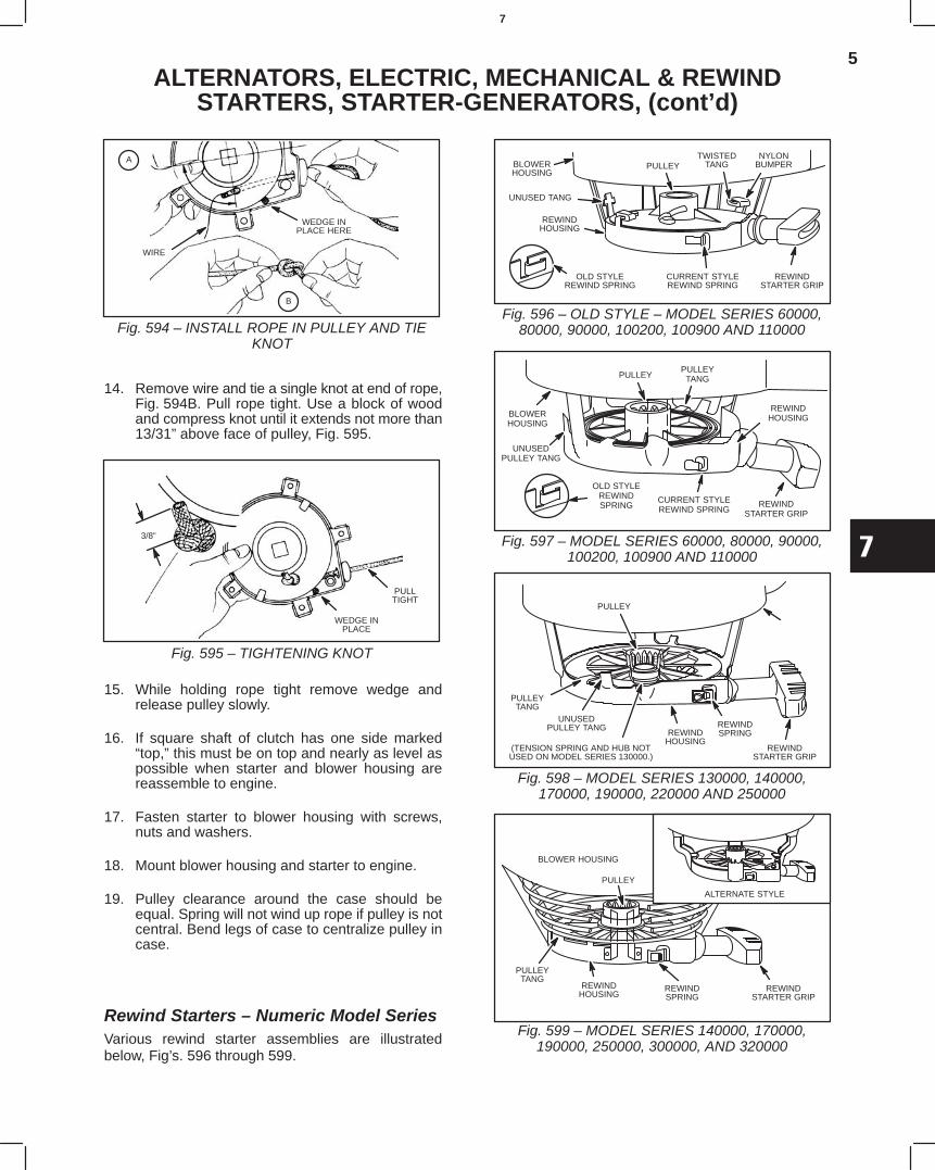
5
7
ALTERNATORS, ELECTRIC, MECHANICAL & REWINDSTARTERS, STARTER-GENERATORS, (cont’d)
Fig. 594 – INSTALL ROPE IN PULLEY AND TIEKNOT
WEDGE INPLACE HERE
WIRE
B
A
14. Remove wire and tie a single knot at end of rope,Fig. 594B. Pull rope tight. Use a block of woodand compress knot until it extends not more than13/31” above face of pulley, Fig. 595.
Fig. 595 – TIGHTENING KNOT
PULLTIGHT
WEDGE INPLACE
3/8”
15. While holding rope tight remove wedge andrelease pulley slowly.
16. If square shaft of clutch has one side marked“top,” this must be on top and nearly as level aspossible when starter and blower housing arereassemble to engine.
17. Fasten starter to blower housing with screws,nuts and washers.
18. Mount blower housing and starter to engine.
19. Pulley clearance around the case should beequal. Spring will not wind up rope if pulley is notcentral. Bend legs of case to centralize pulley incase.
Rewind Starters – Numeric Model SeriesVarious rewind starter assemblies are illustratedbelow, Fig’s. 596 through 599.
Fig. 596 – OLD STYLE – MODEL SERIES 60000,80000, 90000, 100200, 100900 AND 110000
UNUSED TANG
REWINDHOUSING
TWISTEDTANG
OLD STYLEREWIND SPRING
CURRENT STYLEREWIND SPRING
NYLONBUMPER
REWINDSTARTER GRIP
BLOWERHOUSING
PULLEY
UNUSEDPULLEY TANG
PULLEYTANGPULLEY
OLD STYLEREWINDSPRING
CURRENT STYLEREWIND SPRING
REWINDSTARTER GRIP
BLOWERHOUSING
REWINDHOUSING
Fig. 597 – MODEL SERIES 60000, 80000, 90000,100200, 100900 AND 110000
Fig. 598 – MODEL SERIES 130000, 140000,170000, 190000, 220000 AND 250000
PULLEY
REWINDSTARTER GRIP
UNUSEDPULLEY TANG
PULLEY
(TENSION SPRING AND HUB NOTUSED ON MODEL SERIES 130000.)
REWINDSPRING
PULLEYTANG
REWINDHOUSING
Fig. 599 – MODEL SERIES 140000, 170000,190000, 250000, 300000, AND 320000
PULLEYTANG
ALTERNATE STYLE
REWINDHOUSING
REWINDSPRING
REWINDSTARTER GRIP
BLOWER HOUSING
PULLEY
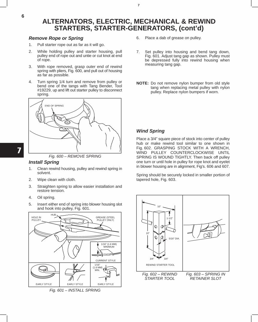
6
7
ALTERNATORS, ELECTRIC, MECHANICAL & REWINDSTARTERS, STARTER-GENERATORS, (cont’d)
Remove Rope or Spring1. Pull starter rope out as far as it will go.
2. While holding pulley and starter housing, pullpulley end of rope out and untie or cut knot at endof rope.
3. With rope removed, grasp outer end of rewindspring with pliers, Fig. 600, and pull out of housingas far as possible.
4. Turn spring 1/4 turn and remove from pulley orbend one of the tangs with Tang Bender, Tool#19229, up and lift out starter pulley to disconnectspring.
END OF SPRING
Fig. 600 – REMOVE SPRING
Install Spring1. Clean rewind housing, pulley and rewind spring in
solvent.
2. Wipe clean with cloth.
3. Straighten spring to allow easier installation andrestore tension.
4. Oil spring.
5. Insert either end of spring into blower housing slotand hook into pulley, Fig. 601.
HOLE INPULLEY
HUBGREASE (STEELPULLEY ONLY)
1/16” (1.6 MM)MINIMUM
CURRENT STYLE
EARLY STYLE EARLY STYLE EARLY STYLE
1/16” (1.6 MM)
MIN.
Fig. 601 – INSTALL SPRING
6. Place a dab of grease on pulley.
7. Set pulley into housing and bend tang down,Fig. 601. Adjust tang gap as shown. Pulley mustbe depressed fully into rewind housing whenmeasuring tang gap.
NOTE: Do not remove nylon bumper from old styletang when replacing metal pulley with nylonpulley. Replace nylon bumpers if worn.
Wind Spring
Place a 3/4” square piece of stock into center of pulleyhub or make rewind tool similar to one shown inFig. 602. GRASPING STOCK WITH A WRENCH,WIND PULLEY COUNTERCLOCKWISE UNTILSPRING IS WOUND TIGHTLY. Then back off pulleyone turn or until hole in pulley for rope knot and eyeletin blower housing are in alignment, Fig’s. 606 and 607.
Spring should be securely locked in smaller portion oftapered hole, Fig. 603.
Fig. 602 – REWINDSTARTER TOOL
Fig. 603 – SPRING INRETAINER SLOT
1-1/2”
REWIND STARTER TOOL
3/4” 3/4”
5/16” DIA.
10”
10”
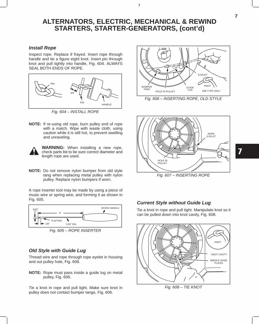
7
7
ALTERNATORS, ELECTRIC, MECHANICAL & REWINDSTARTERS, STARTER-GENERATORS, (cont’d)
Install RopeInspect rope. Replace if frayed. Insert rope throughhandle and tie a figure eight knot. Insert pin throughknot and pull tightly into handle, Fig. 604. ALWAYSSEAL BOTH ENDS OF ROPE.
Fig. 604 – INSTALL ROPE
PIN
3/4”
HANDLEPIN
NOTE: If re-using old rope, burn pulley end of ropewith a match. Wipe with waste cloth, usingcaution while it is still hot, to prevent swellingand unraveling.
WARNING: When installing a new rope,check parts list to be sure correct diameter andlength rope are used.
NOTE: Do not remove nylon bumper from old styletang when replacing metal pulley with nylonpulley. Replace nylon bumpers if worn.
A rope inserter tool may be made by using a piece ofmusic wire or spring wire, and forming it as shown inFig. 605.
Fig. 605 – ROPE INSERTER
3/32”
6”
1/8”FLATTEN
1/16” DIA.
WOOD HANDLE
Old Style with Guide LugThread wire and rope through rope eyelet in housingand out pulley hole, Fig. 606.
NOTE: Rope must pass inside a guide lug on metalpulley, Fig. 606.
Tie a knot in rope and pull tight. Make sure knot inpulley does not contact bumper tangs, Fig. 606.
Fig. 606 – INSERTING ROPE, OLD STYLE
BUMPERTANG
HOLE IN PULLEY
GUIDELUG
KNOT
RIB TYPE ONLY
EYELET
ROPEEYELET
Fig. 607 – INSERTING ROPE
HOLE INPULLEY
Current Style without Guide LugTie a knot in rope and pull tight. Manipulate knot so itcan be pulled down into knot cavity, Fig. 608.
KNOT CAVITY
KNOT
NEEDLE NOSEPLIERS
Fig. 608 – TIE KNOT
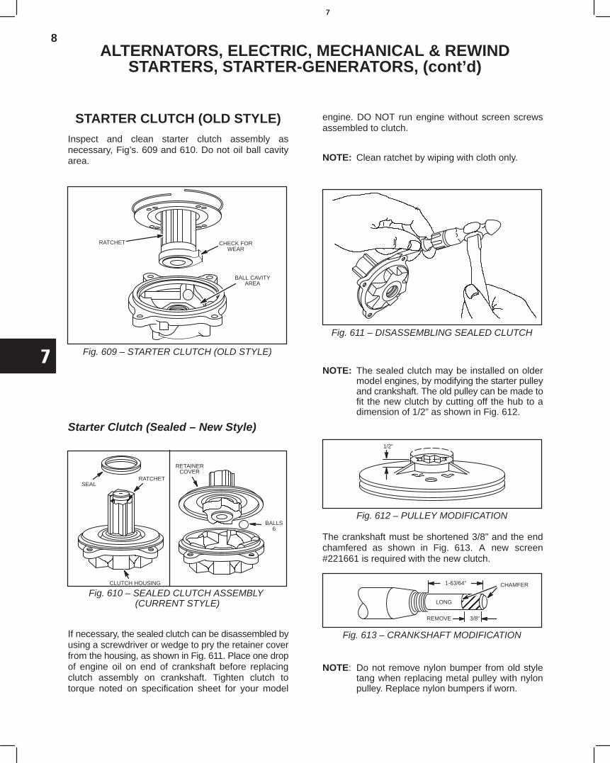
8
7
ALTERNATORS, ELECTRIC, MECHANICAL & REWINDSTARTERS, STARTER-GENERATORS, (cont’d)
STARTER CLUTCH (OLD STYLE)Inspect and clean starter clutch assembly asnecessary, Fig’s. 609 and 610. Do not oil ball cavityarea.
RATCHET CHECK FORWEAR
BALL CAVITYAREA
Fig. 609 – STARTER CLUTCH (OLD STYLE)
Starter Clutch (Sealed – New Style)
Fig. 610 – SEALED CLUTCH ASSEMBLY (CURRENT STYLE)
ÍÍÍ
SEALRATCHET
CLUTCH HOUSING
RETAINERCOVER
BALLS6
If necessary, the sealed clutch can be disassembled byusing a screwdriver or wedge to pry the retainer coverfrom the housing, as shown in Fig. 611. Place one dropof engine oil on end of crankshaft before replacingclutch assembly on crankshaft. Tighten clutch totorque noted on specification sheet for your model
engine. DO NOT run engine without screen screwsassembled to clutch.
NOTE: Clean ratchet by wiping with cloth only.
Fig. 611 – DISASSEMBLING SEALED CLUTCH
NOTE: The sealed clutch may be installed on oldermodel engines, by modifying the starter pulleyand crankshaft. The old pulley can be made tofit the new clutch by cutting off the hub to adimension of 1/2” as shown in Fig. 612.
Fig. 612 – PULLEY MODIFICATION
1/2”
The crankshaft must be shortened 3/8” and the endchamfered as shown in Fig. 613. A new screen#221661 is required with the new clutch.
Fig. 613 – CRANKSHAFT MODIFICATION
CHAMFER
ÉÉÉÉÉÉREMOVE 3/8”
1-63/64”
LONG
NOTE: Do not remove nylon bumper from old styletang when replacing metal pulley with nylonpulley. Replace nylon bumpers if worn.
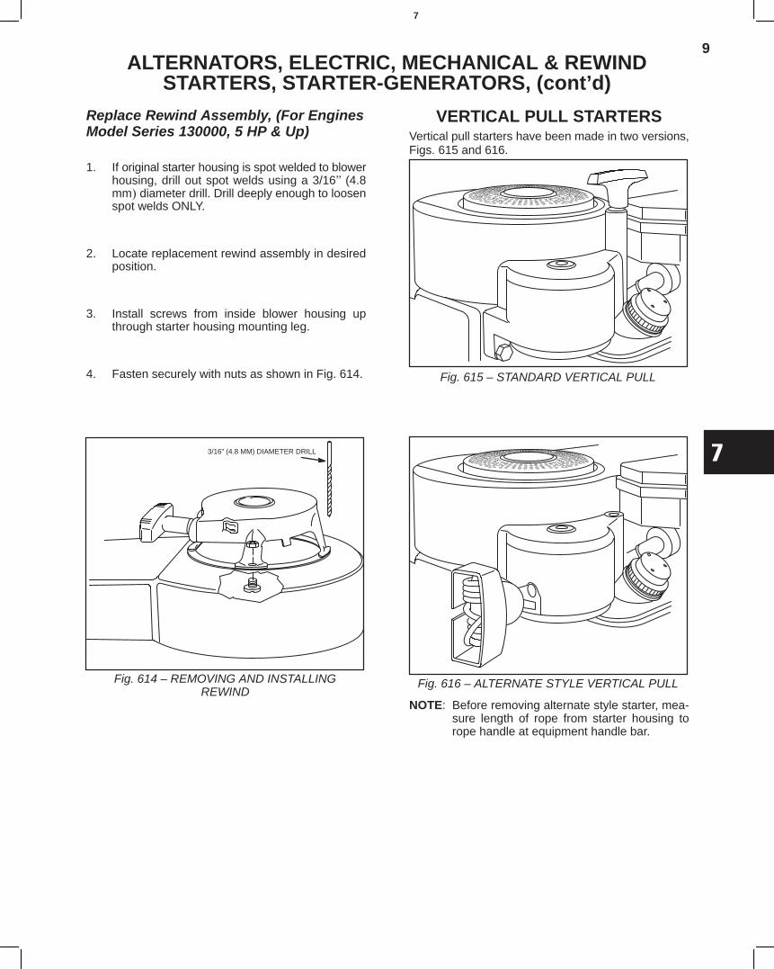
9
7
ALTERNATORS, ELECTRIC, MECHANICAL & REWINDSTARTERS, STARTER-GENERATORS, (cont’d)
Replace Rewind Assembly, (For EnginesModel Series 130000, 5 HP & Up)
1. If original starter housing is spot welded to blowerhousing, drill out spot welds using a 3/16(4.8mm diameter drill. Drill deeply enough to loosenspot welds ONLY.
2. Locate replacement rewind assembly in desiredposition.
3. Install screws from inside blower housing upthrough starter housing mounting leg.
4. Fasten securely with nuts as shown in Fig. 614.
3/16” (4.8 MM) DIAMETER DRILL
Fig. 614 – REMOVING AND INSTALLINGREWIND
VERTICAL PULL STARTERSVertical pull starters have been made in two versions,Figs. 615 and 616.
Fig. 615 – STANDARD VERTICAL PULL
Fig. 616 – ALTERNATE STYLE VERTICAL PULL
NOTE: Before removing alternate style starter, mea-sure length of rope from starter housing torope handle at equipment handle bar.
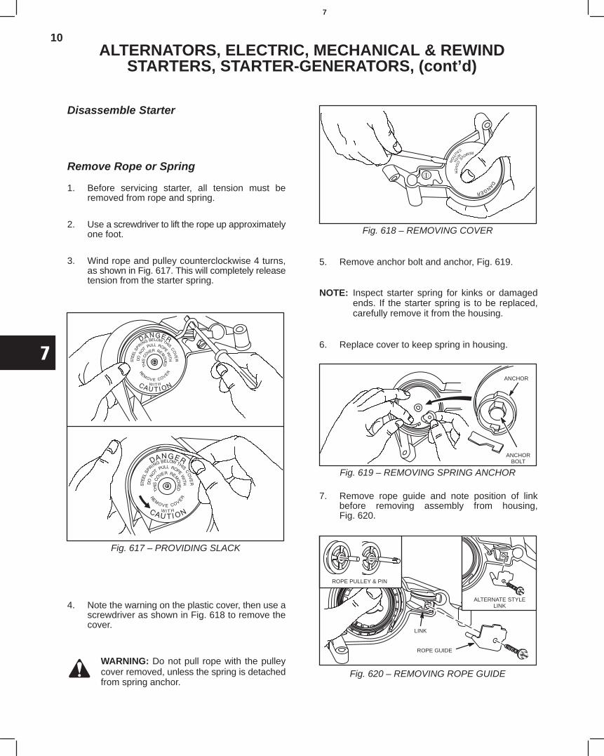
10
7
ALTERNATORS, ELECTRIC, MECHANICAL & REWINDSTARTERS, STARTER-GENERATORS, (cont’d)
Disassemble Starter
Remove Rope or Spring
1. Before servicing starter, all tension must beremoved from rope and spring.
2. Use a screwdriver to lift the rope up approximatelyone foot.
3. Wind rope and pulley counterclockwise 4 turns,as shown in Fig. 617. This will completely releasetension from the starter spring.
Fig. 617 – PROVIDING SLACK
4. Note the warning on the plastic cover, then use ascrewdriver as shown in Fig. 618 to remove thecover.
WARNING: Do not pull rope with the pulleycover removed, unless the spring is detachedfrom spring anchor.
Fig. 618 – REMOVING COVER
5. Remove anchor bolt and anchor, Fig. 619.
NOTE: Inspect starter spring for kinks or damagedends. If the starter spring is to be replaced,carefully remove it from the housing.
6. Replace cover to keep spring in housing.
ANCHOR
ANCHORBOLT
Fig. 619 – REMOVING SPRING ANCHOR
7. Remove rope guide and note position of linkbefore removing assembly from housing,Fig. 620.
ROPE PULLEY & PIN
ALTERNATE STYLELINK
LINK
ROPE GUIDE
Fig. 620 – REMOVING ROPE GUIDE
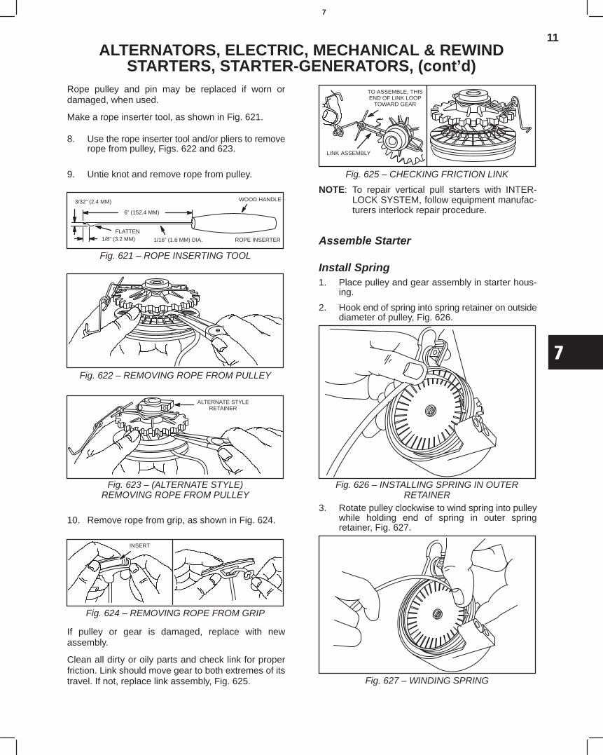
11
7
ALTERNATORS, ELECTRIC, MECHANICAL & REWINDSTARTERS, STARTER-GENERATORS, (cont’d)
Rope pulley and pin may be replaced if worn ordamaged, when used.
Make a rope inserter tool, as shown in Fig. 621.
8. Use the rope inserter tool and/or pliers to removerope from pulley, Figs. 622 and 623.
9. Untie knot and remove rope from pulley.
3/32” (2.4 MM)
6” (152.4 MM)
1/8” (3.2 MM)FLATTEN
1/16” (1.6 MM) DIA.
WOOD HANDLE
ROPE INSERTER
Fig. 621 – ROPE INSERTING TOOL
Fig. 622 – REMOVING ROPE FROM PULLEY
ALTERNATE STYLERETAINER
Fig. 623 – (ALTERNATE STYLE)REMOVING ROPE FROM PULLEY
10. Remove rope from grip, as shown in Fig. 624.
INSERT
Fig. 624 – REMOVING ROPE FROM GRIP
If pulley or gear is damaged, replace with newassembly.
Clean all dirty or oily parts and check link for properfriction. Link should move gear to both extremes of itstravel. If not, replace link assembly, Fig. 625.
TO ASSEMBLE, THISEND OF LINK LOOP
TOWARD GEAR
LINK ASSEMBLY
Fig. 625 – CHECKING FRICTION LINK
NOTE: To repair vertical pull starters with INTER-LOCK SYSTEM, follow equipment manufac-turers interlock repair procedure.
Assemble Starter
Install Spring1. Place pulley and gear assembly in starter hous-
ing.
2. Hook end of spring into spring retainer on outsidediameter of pulley, Fig. 626.
Fig. 626 – INSTALLING SPRING IN OUTERRETAINER
3. Rotate pulley clockwise to wind spring into pulleywhile holding end of spring in outer springretainer, Fig. 627.
Fig. 627 – WINDING SPRING
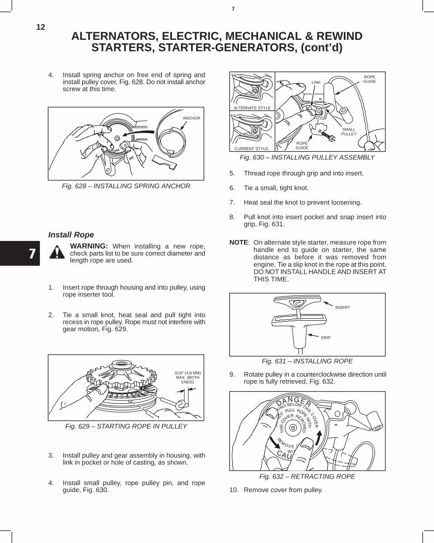
12
7
ALTERNATORS, ELECTRIC, MECHANICAL & REWINDSTARTERS, STARTER-GENERATORS, (cont’d)
4. Install spring anchor on free end of spring andinstall pulley cover, Fig. 628. Do not install anchorscrew at this time.
ANCHOR
Fig. 628 – INSTALLING SPRING ANCHOR
Install RopeWARNING: When installing a new rope,check parts list to be sure correct diameter andlength rope are used.
1. Insert rope through housing and into pulley, usingrope inserter tool.
2. Tie a small knot, heat seal and pull tight intorecess in rope pulley. Rope must not interfere withgear motion, Fig. 629.
3/16” (4.8 MM)MAX. (BOTH
ENDS)
Fig. 629 – STARTING ROPE IN PULLEY
3. Install pulley and gear assembly in housing, withlink in pocket or hole of casting, as shown.
4. Install small pulley, rope pulley pin, and ropeguide, Fig. 630.
ROPEGUIDE
SMALLPULLEY
LINK
ALTERNATE STYLE
CURRENT STYLEROPEGUIDE
Fig. 630 – INSTALLING PULLEY ASSEMBLY
5. Thread rope through grip and into insert.
6. Tie a small, tight knot.
7. Heat seal the knot to prevent loosening.
8. Pull knot into insert pocket and snap insert intogrip, Fig. 631.
NOTE: On alternate style starter, measure rope fromhandle end to guide on starter, the samedistance as before it was removed fromengine. Tie a slip knot in the rope at this point.DO NOT INSTALL HANDLE AND INSERT ATTHIS TIME.
INSERT
GRIP
Fig. 631 – INSTALLING ROPE
9. Rotate pulley in a counterclockwise direction untilrope is fully retrieved, Fig. 632.
Fig. 632 – RETRACTING ROPE
10. Remove cover from pulley.
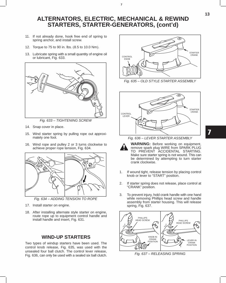
13
7
ALTERNATORS, ELECTRIC, MECHANICAL & REWINDSTARTERS, STARTER-GENERATORS, (cont’d)
11. If not already done, hook free end of spring tospring anchor, and install screw.
12. Torque to 75 to 90 in. lbs.8.5 to 10.0 Nm.
13. Lubricate spring with a small quantity of engine oilor lubricant, Fig. 633.
Fig. 633 – TIGHTENING SCREW
14. Snap cover in place.
15. Wind starter spring by pulling rope out approxi-mately one foot.
16. Wind rope and pulley 2 or 3 turns clockwise toachieve proper rope tension, Fig. 634.
Fig. 634 – ADDING TENSION TO ROPE
17. Install starter on engine.
18. After installing alternate style starter on engine,route rope up to equipment control handle andinstall handle and insert, Fig. 631.
WIND-UP STARTERSTwo types of windup starters have been used. Thecontrol knob release, Fig. 635, was used with theunsealed four ball clutch. The control lever release,Fig. 636, can only be used with a sealed six ball clutch.
CONTROLKNOB
STARTERCRANK
Fig. 635 – OLD STYLE STARTER ASSEMBLY
CONTROLLEVER
STARTERCRANK
Fig. 636 – LEVER STARTER ASSEMBLY
WARNING: Before working on equipment,remove spark plug WIRE from SPARK PLUGTO PREVENT ACCIDENTAL STARTING.Make sure starter spring is not wound. This canbe determined by attempting to turn startercrank clockwise.
1. If wound tight, release tension by placing controlknob or lever to “START” position.
2. If starter spring does not release, place control at“CRANK” position.
3. To prevent injury, hold crank handle with one handwhile removing Phillips head screw and handleassembly from starter housing. This will releasespring, Fig. 637.
PHILLIPSHEAD SCREW
KNOB INCRANK
POSITIONLEVER INCRANK
POSITION
PHILLIPSHEAD SCREW
Fig. 637 – RELEASING SPRING
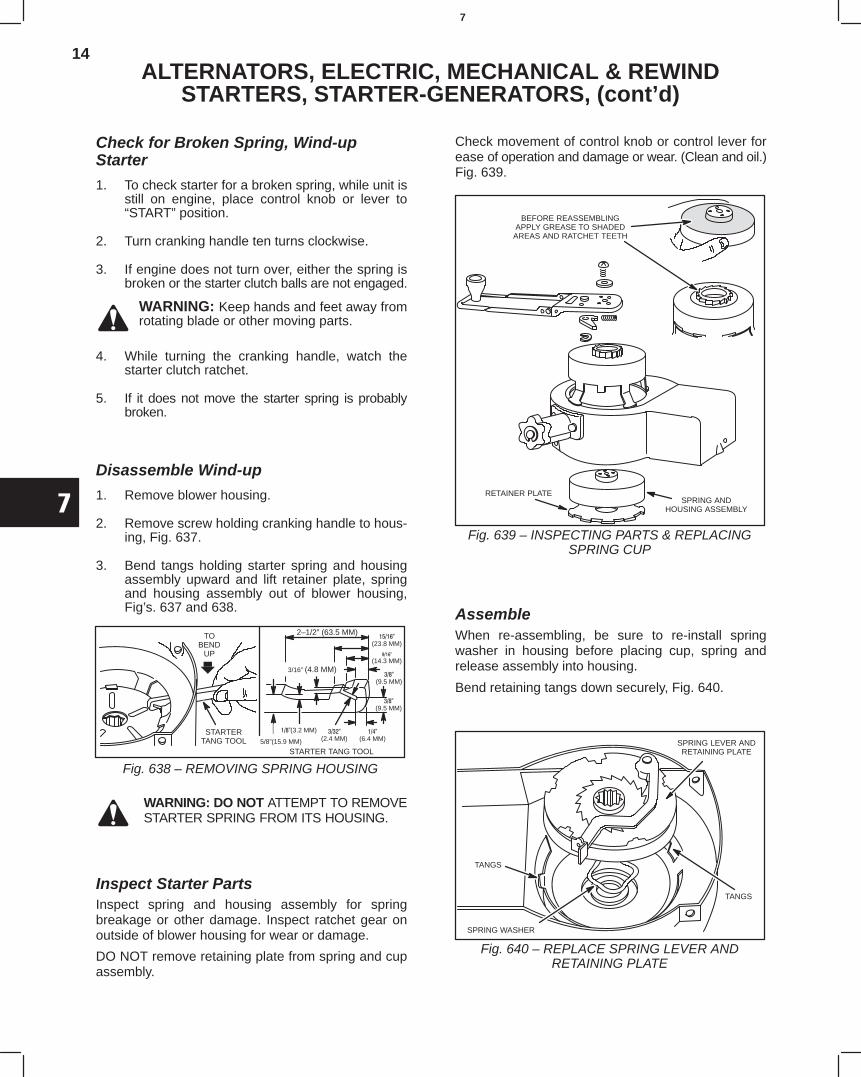
14
7
ALTERNATORS, ELECTRIC, MECHANICAL & REWINDSTARTERS, STARTER-GENERATORS, (cont’d)
Check for Broken Spring, Wind-upStarter
1. To check starter for a broken spring, while unit isstill on engine, place control knob or lever to“START” position.
2. Turn cranking handle ten turns clockwise.
3. If engine does not turn over, either the spring isbroken or the starter clutch balls are not engaged.
WARNING: Keep hands and feet away fromrotating blade or other moving parts.
4. While turning the cranking handle, watch thestarter clutch ratchet.
5. If it does not move the starter spring is probablybroken.
Disassemble Wind-up
1. Remove blower housing.
2. Remove screw holding cranking handle to hous-ing, Fig. 637.
3. Bend tangs holding starter spring and housingassembly upward and lift retainer plate, springand housing assembly out of blower housing,Fig’s. 637 and 638.
2–1/2” (63.5 MM)
(23.8 MM)
(14.3 MM)
(9.5 MM)
3/16” (4.8 MM)
(3.2 MM)
5/8”(15.9 MM)
(6.4 MM)
(2.4 MM)
TOBEND
UP
STARTERTANG TOOL
STARTER TANG TOOL
Fig. 638 – REMOVING SPRING HOUSING
(9.5 MM)
WARNING: DO NOT ATTEMPT TO REMOVESTARTER SPRING FROM ITS HOUSING.
Inspect Starter PartsInspect spring and housing assembly for springbreakage or other damage. Inspect ratchet gear onoutside of blower housing for wear or damage.
DO NOT remove retaining plate from spring and cupassembly.
Check movement of control knob or control lever forease of operation and damage or wear. (Clean and oil.)Fig. 639.
BEFORE REASSEMBLINGAPPLY GREASE TO SHADED
AREAS AND RATCHET TEETH
SPRING ANDHOUSING ASSEMBLY
RETAINER PLATE
Fig. 639 – INSPECTING PARTS & REPLACINGSPRING CUP
AssembleWhen re-assembling, be sure to re-install springwasher in housing before placing cup, spring andrelease assembly into housing.
Bend retaining tangs down securely, Fig. 640.
SPRING LEVER ANDRETAINING PLATE
TANGS
SPRING WASHER
TANGS
Fig. 640 – REPLACE SPRING LEVER ANDRETAINING PLATE
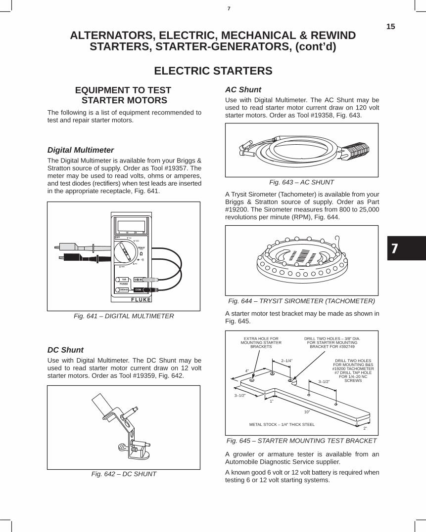
15
7
ALTERNATORS, ELECTRIC, MECHANICAL & REWINDSTARTERS, STARTER-GENERATORS, (cont’d)
ELECTRIC STARTERS
EQUIPMENT TO TEST STARTER MOTORS
The following is a list of equipment recommended totest and repair starter motors.
Digital MultimeterThe Digital Multimeter is available from your Briggs &Stratton source of supply. Order as Tool #19357. Themeter may be used to read volts, ohms or amperes,and test diodes (rectifiers) when test leads are insertedin the appropriate receptacle, Fig. 641.
Fig. 641 – DIGITAL MULTIMETER
DC ShuntUse with Digital Multimeter. The DC Shunt may beused to read starter motor current draw on 12 voltstarter motors. Order as Tool #19359, Fig. 642.
Fig. 642 – DC SHUNT
AC ShuntUse with Digital Multimeter. The AC Shunt may beused to read starter motor current draw on 120 voltstarter motors. Order as Tool #19358, Fig. 643.
Fig. 643 – AC SHUNT
A Trysit Sirometer (Tachometer) is available from yourBriggs & Stratton source of supply. Order as Part#19200. The Sirometer measures from 800 to 25,000revolutions per minute (RPM), Fig. 644.
Fig. 644 – TRYSIT SIROMETER (TACHOMETER)
A starter motor test bracket may be made as shown inFig. 645.
2–1/4”
3–1/2”
2”
10”
1”
3–1/2”
4”
EXTRA HOLE FORMOUNTING STARTER
BRACKETS
DRILL TWO HOLES – 3/8” DIA.FOR STARTER MOUNTING
BRACKET FOR #392749
DRILL TWO HOLESFOR MOUNTING B&S#19200 TACHOMETER
#7 DRILL TAP HOLEFOR 1/4–20 NC
SCREWS
METAL STOCK – 1/4” THICK STEEL
Fig. 645 – STARTER MOUNTING TEST BRACKET
A growler or armature tester is available from anAutomobile Diagnostic Service supplier.
A known good 6 volt or 12 volt battery is required whentesting 6 or 12 volt starting systems.
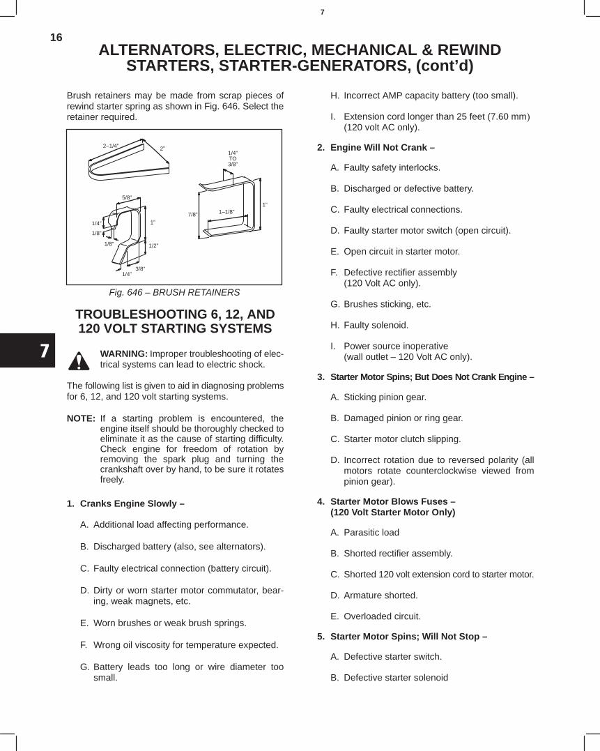
16
7
ALTERNATORS, ELECTRIC, MECHANICAL & REWINDSTARTERS, STARTER-GENERATORS, (cont’d)
Brush retainers may be made from scrap pieces ofrewind starter spring as shown in Fig. 646. Select theretainer required.
2–1/4” 2”1/4”TO3/8”
1”1–1/8”7/8”
5/8”
1/4”
1/8”
1/8”
1”
1/2”
1/4”3/8”
Fig. 646 – BRUSH RETAINERS
TROUBLESHOOTING 6, 12, AND120 VOLT STARTING SYSTEMS
WARNING: Improper troubleshooting of elec-trical systems can lead to electric shock.
The following list is given to aid in diagnosing problemsfor 6, 12, and 120 volt starting systems.
NOTE: If a starting problem is encountered, theengine itself should be thoroughly checked toeliminate it as the cause of starting difficulty.Check engine for freedom of rotation byremoving the spark plug and turning thecrankshaft over by hand, to be sure it rotatesfreely.
1. Cranks Engine Slowly –
A. Additional load affecting performance.
B. Discharged battery (also, see alternators).
C. Faulty electrical connection (battery circuit).
D. Dirty or worn starter motor commutator, bear-ing, weak magnets, etc.
E. Worn brushes or weak brush springs.
F. Wrong oil viscosity for temperature expected.
G. Battery leads too long or wire diameter toosmall.
H. Incorrect AMP capacity battery (too small).
I. Extension cord longer than 25 feet (7.60 mm(120 volt AC only).
2. Engine Will Not Crank –
A. Faulty safety interlocks.
B. Discharged or defective battery.
C. Faulty electrical connections.
D. Faulty starter motor switch (open circuit).
E. Open circuit in starter motor.
F. Defective rectifier assembly(120 Volt AC only).
G. Brushes sticking, etc.
H. Faulty solenoid.
I. Power source inoperative(wall outlet – 120 Volt AC only).
3. Starter Motor Spins; But Does Not Crank Engine –
A. Sticking pinion gear.
B. Damaged pinion or ring gear.
C. Starter motor clutch slipping.
D. Incorrect rotation due to reversed polarity (allmotors rotate counterclockwise viewed frompinion gear).
4. Starter Motor Blows Fuses –(120 Volt Starter Motor Only)
A. Parasitic load
B. Shorted rectifier assembly.
C. Shorted 120 volt extension cord to starter motor.
D. Armature shorted.
E. Overloaded circuit.
5. Starter Motor Spins; Will Not Stop –
A. Defective starter switch.
B. Defective starter solenoid
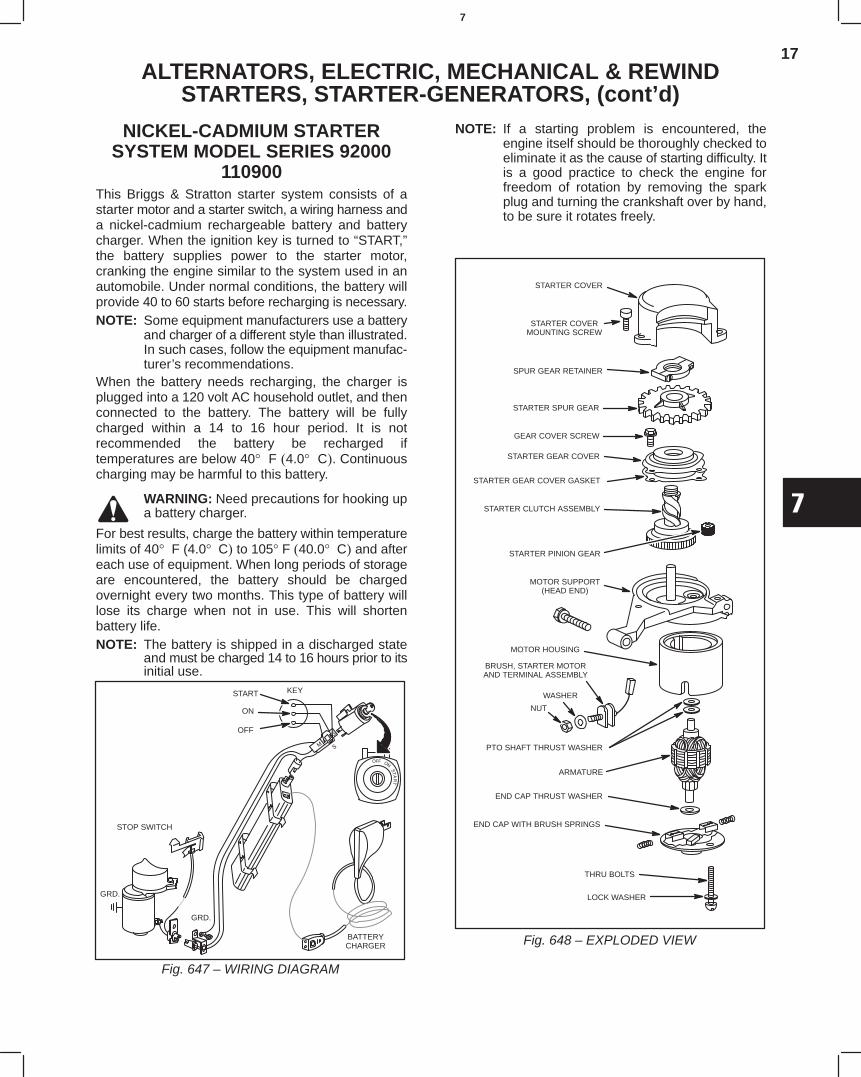
17
7
ALTERNATORS, ELECTRIC, MECHANICAL & REWINDSTARTERS, STARTER-GENERATORS, (cont’d)
NICKEL-CADMIUM STARTERSYSTEM MODEL SERIES 92000
110900This Briggs & Stratton starter system consists of astarter motor and a starter switch, a wiring harness anda nickel-cadmium rechargeable battery and batterycharger. When the ignition key is turned to “START,”the battery supplies power to the starter motor,cranking the engine similar to the system used in anautomobile. Under normal conditions, the battery willprovide 40 to 60 starts before recharging is necessary.NOTE: Some equipment manufacturers use a battery
and charger of a different style than illustrated.In such cases, follow the equipment manufac-turer’s recommendations.
When the battery needs recharging, the charger isplugged into a 120 volt AC household outlet, and thenconnected to the battery. The battery will be fullycharged within a 14 to 16 hour period. It is notrecommended the battery be recharged iftemperatures are below 40° F 4.0° C. Continuouscharging may be harmful to this battery.
WARNING: Need precautions for hooking upa battery charger.
For best results, charge the battery within temperaturelimits of 40° F (4.0° C to 105° F 40.0° C and aftereach use of equipment. When long periods of storageare encountered, the battery should be chargedovernight every two months. This type of battery willlose its charge when not in use. This will shortenbattery life.NOTE: The battery is shipped in a discharged state
and must be charged 14 to 16 hours prior to itsinitial use.
START
ON
OFF
STOP SWITCH
GRD.
GRD.
BATTERYCHARGER
KEY
Fig. 647 – WIRING DIAGRAM
NOTE: If a starting problem is encountered, theengine itself should be thoroughly checked toeliminate it as the cause of starting difficulty. Itis a good practice to check the engine forfreedom of rotation by removing the sparkplug and turning the crankshaft over by hand,to be sure it rotates freely.
STARTER COVER
STARTER COVERMOUNTING SCREW
SPUR GEAR RETAINER
STARTER SPUR GEAR
GEAR COVER SCREW
STARTER GEAR COVER GASKET
STARTER GEAR COVER
STARTER CLUTCH ASSEMBLY
STARTER PINION GEAR
MOTOR SUPPORT(HEAD END)
BRUSH, STARTER MOTORAND TERMINAL ASSEMBLY
MOTOR HOUSING
WASHER
NUT
PTO SHAFT THRUST WASHER
ARMATURE
END CAP THRUST WASHER
END CAP WITH BRUSH SPRINGS
THRU BOLTS
LOCK WASHER
Fig. 648 – EXPLODED VIEW
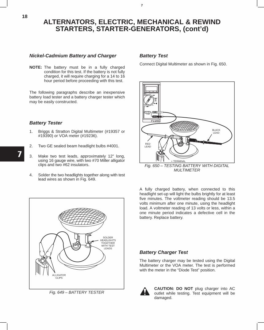
18
7
ALTERNATORS, ELECTRIC, MECHANICAL & REWINDSTARTERS, STARTER-GENERATORS, (cont’d)
Nickel-Cadmium Battery and Charger
NOTE: The battery must be in a fully chargedcondition for this test. If the battery is not fullycharged, it will require charging for a 14 to 16hour period before proceeding with this test.
The following paragraphs describe an inexpensivebattery load tester and a battery charger tester whichmay be easily constructed.
Battery Tester
1. Briggs & Stratton Digital Multimeter (#19357 or#19390) or VOA meter (#19236).
2. Two GE sealed beam headlight bulbs #4001.
3. Make two test leads, approximately 12” long,using 16 gauge wire, with two #70 Miller alligatorclips and two #62 insulators.
4. Solder the two headlights together along with testlead wires as shown in Fig. 649.
ALLIGATORCLIPS
SOLDERHEADLIGHTSTOGETHERWITH TEST
LEADS
Fig. 649 – BATTERY TESTER
Battery Test
Connect Digital Multimeter as shown in Fig. 650.
BLACKLEAD
REDLEAD
+ TERMINAL
Fig. 650 – TESTING BATTERY WITH DIGITALMULTIMETER
A fully charged battery, when connected to thisheadlight set-up will light the bulbs brightly for at leastfive minutes. The voltmeter reading should be 13.5volts minimum after one minute, using the headlightload. A voltmeter reading of 13 volts or less, within aone minute period indicates a defective cell in thebattery. Replace battery.
Battery Charger Test
The battery charger may be tested using the DigitalMultimeter or the VOA meter. The test is performedwith the meter in the “Diode Test” position.
CAUTION: DO NOT plug charger into ACoutlet while testing. Test equipment will bedamaged.
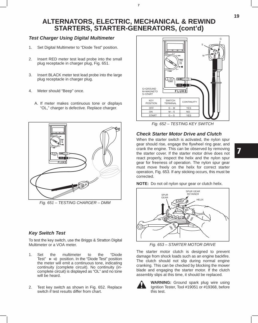
19
7
ALTERNATORS, ELECTRIC, MECHANICAL & REWINDSTARTERS, STARTER-GENERATORS, (cont’d)
Test Charger Using Digital Multimeter
1. Set Digital Multimeter to “Diode Test” position.
2. Insert RED meter test lead probe into the smallplug receptacle in charger plug, Fig. 651.
3. Insert BLACK meter test lead probe into the largeplug receptacle in charger plug.
4. Meter should “Beep” once.
A. If meter makes continuous tone or displays“OL,” charger is defective. Replace charger.
Fig. 651 – TESTING CHARGER – DMM
Key Switch TestTo test the key switch, use the Briggs & Stratton DigitalMultimeter or a VOA meter.
1. Set the multimeter to the “DiodeTest” position. In the “Diode Test” positionthe meter will emit a continuous tone, indicatingcontinuity (complete circuit). No continuity (in-complete circuit) is displayed as “OL” and no tonewill be heard.
2. Test key switch as shown in Fig. 652. Replaceswitch if test results differ from chart.
M
S
G
G=GROUNDM=MAGNETOS=START
OFF G – M YES
ON M – S NO
START G – S YES
KEYPOSITION
SWITCHTERMINAL CONTINUITY
Fig. 652 – TESTING KEY SWITCH
Check Starter Motor Drive and ClutchWhen the starter switch is activated, the nylon spurgear should rise, engage the flywheel ring gear, andcrank the engine. This can be observed by removingthe starter cover. If the starter motor drive does notreact properly, inspect the helix and the nylon spurgear for freeness of operation. The nylon spur gearmust move freely on the helix for correct starteroperation, Fig. 653. If any sticking occurs, this must becorrected.
NOTE: Do not oil nylon spur gear or clutch helix.
SPURGEAR
SPUR GEARRETAINER
HELIX
Fig. 653 – STARTER MOTOR DRIVE
The starter motor clutch is designed to preventdamage from shock loads such as an engine backfire.The clutch should not slip during normal enginecranking. This can be checked by blocking the mowerblade and engaging the starter motor. If the clutchassembly slips at this time, it should be replaced.
WARNING: Ground spark plug wire usingIgnition Tester, Tool #19051 or #19368, beforethis test.
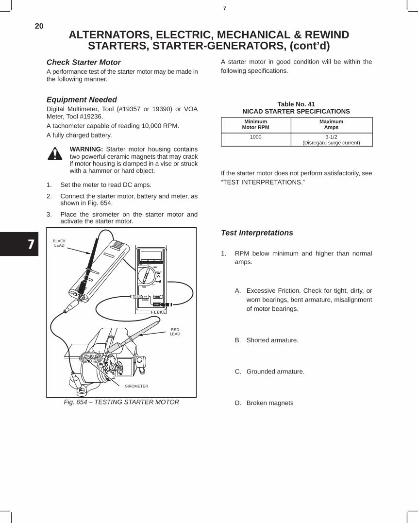
20
7
ALTERNATORS, ELECTRIC, MECHANICAL & REWINDSTARTERS, STARTER-GENERATORS, (cont’d)
Check Starter MotorA performance test of the starter motor may be made inthe following manner.
Equipment NeededDigital Multimeter, Tool (#19357 or 19390) or VOAMeter, Tool #19236.
A tachometer capable of reading 10,000 RPM.
A fully charged battery.
WARNING: Starter motor housing containstwo powerful ceramic magnets that may crackif motor housing is clamped in a vise or struckwith a hammer or hard object.
1. Set the meter to read DC amps.
2. Connect the starter motor, battery and meter, asshown in Fig. 654.
3. Place the sirometer on the starter motor andactivate the starter motor.
BLACKLEAD
REDLEAD
SIROMETER
Fig. 654 – TESTING STARTER MOTOR
A starter motor in good condition will be within thefollowing specifications.
Table No. 41NICAD STARTER SPECIFICATIONS
MinimumMotor RPM
MaximumAmps
1000 3-1/2(Disregard surge current)
If the starter motor does not perform satisfactorily, see“TEST INTERPRETATIONS.”
Test Interpretations
1. RPM below minimum and higher than normalamps.
A. Excessive Friction. Check for tight, dirty, orworn bearings, bent armature, misalignmentof motor bearings.
B. Shorted armature.
C. Grounded armature.
D. Broken magnets
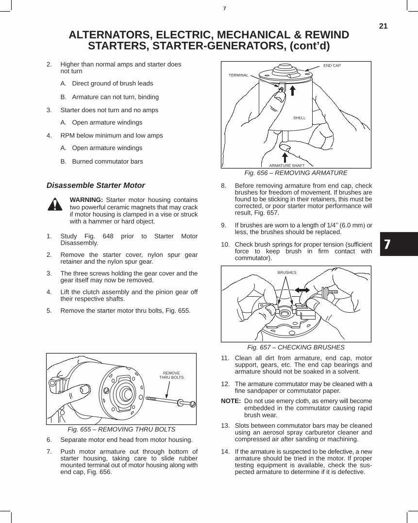
21
7
ALTERNATORS, ELECTRIC, MECHANICAL & REWINDSTARTERS, STARTER-GENERATORS, (cont’d)
2. Higher than normal amps and starter doesnot turn
A. Direct ground of brush leads
B. Armature can not turn, binding
3. Starter does not turn and no amps
A. Open armature windings
4. RPM below minimum and low amps
A. Open armature windings
B. Burned commutator bars
Disassemble Starter Motor
WARNING: Starter motor housing containstwo powerful ceramic magnets that may crackif motor housing is clamped in a vise or struckwith a hammer or hard object.
1. Study Fig. 648 prior to Starter MotorDisassembly.
2. Remove the starter cover, nylon spur gearretainer and the nylon spur gear.
3. The three screws holding the gear cover and thegear itself may now be removed.
4. Lift the clutch assembly and the pinion gear offtheir respective shafts.
5. Remove the starter motor thru bolts, Fig. 655.
REMOVETHRU BOLTS
Fig. 655 – REMOVING THRU BOLTS
6. Separate motor end head from motor housing.
7. Push motor armature out through bottom ofstarter housing, taking care to slide rubbermounted terminal out of motor housing along withend cap, Fig. 656.
TERMINAL
ARMATURE SHAFT
SHELL
END CAP
Fig. 656 – REMOVING ARMATURE
8. Before removing armature from end cap, checkbrushes for freedom of movement. If brushes arefound to be sticking in their retainers, this must becorrected, or poor starter motor performance willresult, Fig. 657.
9. If brushes are worn to a length of 1/4(6.0 mm orless, the brushes should be replaced.
10. Check brush springs for proper tension (sufficientforce to keep brush in firm contact withcommutator).
BRUSHES
Fig. 657 – CHECKING BRUSHES
11. Clean all dirt from armature, end cap, motorsupport, gears, etc. The end cap bearings andarmature should not be soaked in a solvent.
12. The armature commutator may be cleaned with afine sandpaper or commutator paper.
NOTE: Do not use emery cloth, as emery will becomeembedded in the commutator causing rapidbrush wear.
13. Slots between commutator bars may be cleanedusing an aerosol spray carburetor cleaner andcompressed air after sanding or machining.
14. If the armature is suspected to be defective, a newarmature should be tried in the motor. If propertesting equipment is available, check the sus-pected armature to determine if it is defective.
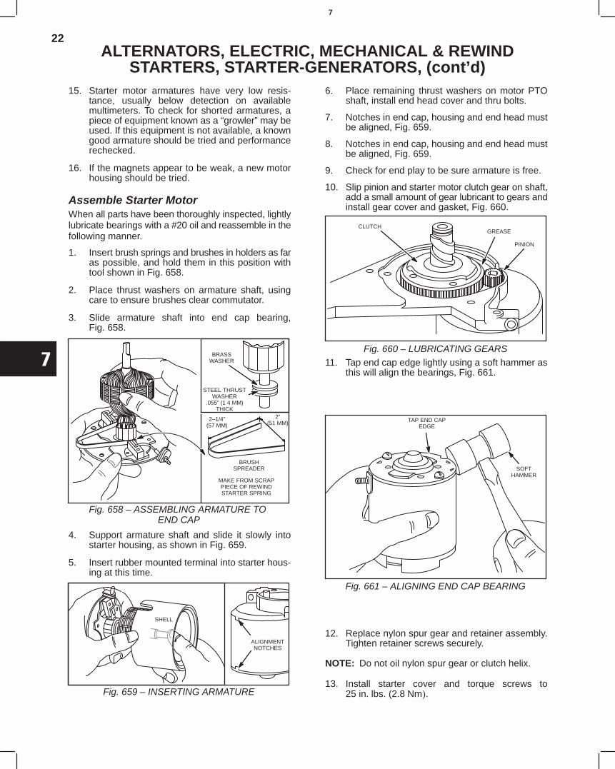
22
7
ALTERNATORS, ELECTRIC, MECHANICAL & REWINDSTARTERS, STARTER-GENERATORS, (cont’d)
15. Starter motor armatures have very low resis-tance, usually below detection on availablemultimeters. To check for shorted armatures, apiece of equipment known as a “growler” may beused. If this equipment is not available, a knowngood armature should be tried and performancerechecked.
16. If the magnets appear to be weak, a new motorhousing should be tried.
Assemble Starter MotorWhen all parts have been thoroughly inspected, lightlylubricate bearings with a #20 oil and reassemble in thefollowing manner.
1. Insert brush springs and brushes in holders as faras possible, and hold them in this position withtool shown in Fig. 658.
2. Place thrust washers on armature shaft, usingcare to ensure brushes clear commutator.
3. Slide armature shaft into end cap bearing,Fig. 658.
2–1/4”(57 MM)
2”(51 MM)
BRASSWASHER
BRUSHSPREADER
MAKE FROM SCRAPPIECE OF REWINDSTARTER SPRING
Fig. 658 – ASSEMBLING ARMATURE TO END CAP
STEEL THRUSTWASHER
.055” (1 4 MM)THICK
4. Support armature shaft and slide it slowly intostarter housing, as shown in Fig. 659.
5. Insert rubber mounted terminal into starter hous-ing at this time.
ALIGNMENTNOTCHES
SHELL
Fig. 659 – INSERTING ARMATURE
6. Place remaining thrust washers on motor PTOshaft, install end head cover and thru bolts.
7. Notches in end cap, housing and end head mustbe aligned, Fig. 659.
8. Notches in end cap, housing and end head mustbe aligned, Fig. 659.
9. Check for end play to be sure armature is free.
10. Slip pinion and starter motor clutch gear on shaft,add a small amount of gear lubricant to gears andinstall gear cover and gasket, Fig. 660.
CLUTCHGREASE
PINION
Fig. 660 – LUBRICATING GEARS11. Tap end cap edge lightly using a soft hammer as
this will align the bearings, Fig. 661.
TAP END CAPEDGE
SOFTHAMMER
Fig. 661 – ALIGNING END CAP BEARING
12. Replace nylon spur gear and retainer assembly.Tighten retainer screws securely.
NOTE: Do not oil nylon spur gear or clutch helix.
13. Install starter cover and torque screws to25 in lbs. (2.8Nm.
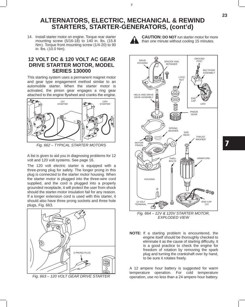
23
7
ALTERNATORS, ELECTRIC, MECHANICAL & REWINDSTARTERS, STARTER-GENERATORS, (cont’d)
14. Install starter motor on engine. Torque rear startermounting screw (5/16-18) to 140 in. lb (15.8Nm. Torque front mounting screw (1/4-20) to 90in. lbs.10.0 Nm).
12 VOLT DC & 120 VOLT AC GEARDRIVE STARTER MOTOR, MODEL
SERIES 130000This starting system uses a permanent magnet motorand gear type engagement method similar to anautomobile starter. When the starter motor isactivated, the pinion gear engages a ring gearattached to the engine flywheel and cranks the engine.
12VSTARTER
120VSTARTER
Fig. 662 – TYPICAL STARTER MOTORS
A list is given to aid you in diagnosing problems for 12volt and 120 volt systems. See page 16.
The 120 volt electric starter is equipped with athree-prong plug for safety. The longer prong in thisplug is connected to the starter motor housing. Whenthe starter motor is plugged into the three-wire cordsupplied, and the cord is plugged into a properlygrounded receptacle, it will protect the user from shockshould the starter-motor insulation fail for any reason.If a longer extension cord is used with this starter, itshould also have three prong sockets and three holeplugs, Fig. 663.
3 PRONG PLUG
Fig. 663 – 120 VOLT GEAR DRIVE STARTER
CAUTION: DO NOT run starter motor for morethan one minute without cooling 15 minutes.
LOCKNUT
PINIONGEAR
HELIX AND DRIVEGEAR ASSEMBLY
MOTORPINION
SPRINGWASHER
ENDHEAD
THRUBOLTS
THRUSTWASHER
ARMATURE
END CAP12V
12 VOLTTERMINAL
HOUSING
Fig. 664 – 12V & 120V STARTER MOTOR,EXPLODED VIEW
GROUNDPOST
RECTIFIERASSEMBLY
ENDCAP
120V
DRIVEHOUSING
SPACER ANDRETAINER
NOTE: If a starting problem is encountered, theengine itself should be thoroughly checked toeliminate it as the cause of starting difficulty. Itis a good practice to check the engine forfreedom of rotation by removing the sparkplug and turning the crankshaft over by hand,to be sure it rotates freely.
A 12 ampere hour battery is suggested for warmtemperature operation. For cold temperatureoperation, use no less than a 24 ampere hour battery.
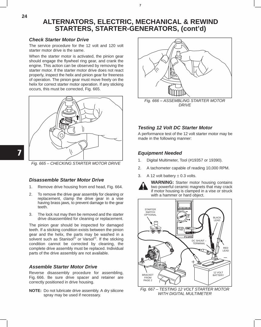
24
7
ALTERNATORS, ELECTRIC, MECHANICAL & REWINDSTARTERS, STARTER-GENERATORS, (cont’d)
Check Starter Motor DriveThe service procedure for the 12 volt and 120 voltstarter motor drive is the same.
When the starter motor is activated, the pinion gearshould engage the flywheel ring gear, and crank theengine. This action can be observed by removing thestarter motor. If the starter motor drive does not reactproperly, inspect the helix and pinion gear for freenessof operation. The pinion gear must move freely on thehelix for correct starter motor operation. If any stickingoccurs, this must be corrected, Fig. 665.
Fig. 665 – CHECKING STARTER MOTOR DRIVE
Disassemble Starter Motor Drive1. Remove drive housing from end head, Fig. 664.
2. To remove the drive gear assembly for cleaning orreplacement, clamp the drive gear in a visehaving brass jaws, to prevent damage to the gearteeth.
3. The lock nut may then be removed and the starterdrive disassembled for cleaning or replacement.
The pinion gear should be inspected for damagedteeth. If a sticking condition exists between the piniongear and the helix, the parts may be washed in asolvent such as Stanisol or Varsol. If the stickingcondition cannot be corrected by cleaning, thecomplete drive assembly must be replaced. Individualparts of the drive assembly are not available.
Assemble Starter Motor DriveReverse disassembly procedure for assembling,Fig. 666. Be sure drive spacer and retainer arecorrectly positioned in drive housing.
NOTE: Do not lubricate drive assembly. A dry siliconespray may be used if necessary.
Fig. 666 – ASSEMBLING STARTER MOTORDRIVE
Testing 12 Volt DC Starter MotorA performance test of the 12 volt starter motor may bemade in the following manner:
Equipment Needed1. Digital Multimeter, Tool (#19357 or 19390).
2. A tachometer capable of reading 10,000 RPM.
3. A 12 volt battery ± 0.3 volts.
WARNING: Starter motor housing containstwo powerful ceramic magnets that may crackif motor housing is clamped in a vise or struckwith a hammer or hard object.
Fig. 667 – TESTING 12 VOLT STARTER MOTORWITH DIGITAL MULTIMETER
REDLEAD
BLACKLEAD
DC SHUNT –TERMINAL
12 VOLTBATTERY
STARTERSWITCH
OPTIONAL
BRACKETFROM
PAGE 2
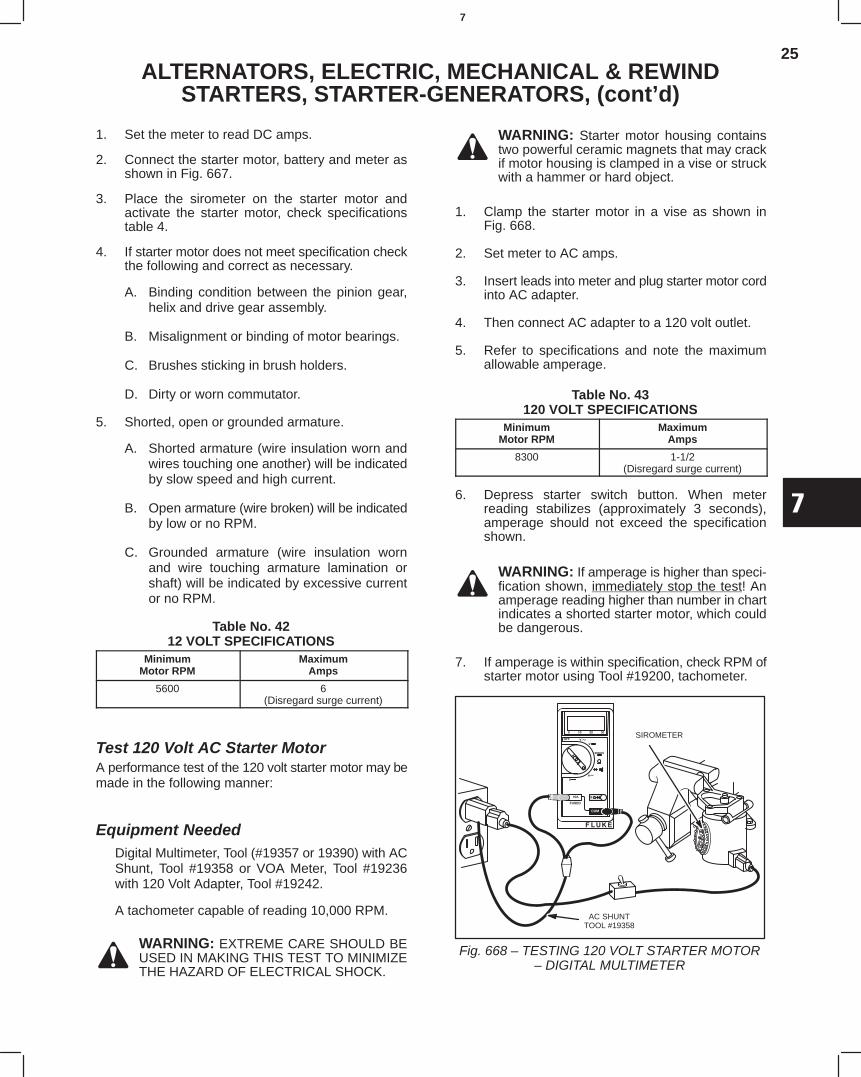
25
7
ALTERNATORS, ELECTRIC, MECHANICAL & REWINDSTARTERS, STARTER-GENERATORS, (cont’d)
1. Set the meter to read DC amps.
2. Connect the starter motor, battery and meter asshown in Fig. 667.
3. Place the sirometer on the starter motor andactivate the starter motor, check specificationstable 4.
4. If starter motor does not meet specification checkthe following and correct as necessary.
A. Binding condition between the pinion gear,helix and drive gear assembly.
B. Misalignment or binding of motor bearings.
C. Brushes sticking in brush holders.
D. Dirty or worn commutator.
5. Shorted, open or grounded armature.
A. Shorted armature (wire insulation worn andwires touching one another) will be indicatedby slow speed and high current.
B. Open armature (wire broken) will be indicatedby low or no RPM.
C. Grounded armature (wire insulation wornand wire touching armature lamination orshaft) will be indicated by excessive currentor no RPM.
Table No. 4212 VOLT SPECIFICATIONS
MinimumMotor RPM
MaximumAmps
5600 6(Disregard surge current)
Test 120 Volt AC Starter MotorA performance test of the 120 volt starter motor may bemade in the following manner:
Equipment NeededDigital Multimeter, Tool (#19357 or 19390) with ACShunt, Tool #19358 or VOA Meter, Tool #19236with 120 Volt Adapter, Tool #19242.
A tachometer capable of reading 10,000 RPM.
WARNING: EXTREME CARE SHOULD BEUSED IN MAKING THIS TEST TO MINIMIZETHE HAZARD OF ELECTRICAL SHOCK.
WARNING: Starter motor housing containstwo powerful ceramic magnets that may crackif motor housing is clamped in a vise or struckwith a hammer or hard object.
1. Clamp the starter motor in a vise as shown inFig. 668.
2. Set meter to AC amps.
3. Insert leads into meter and plug starter motor cordinto AC adapter.
4. Then connect AC adapter to a 120 volt outlet.
5. Refer to specifications and note the maximumallowable amperage.
Table No. 43120 VOLT SPECIFICATIONS
MinimumMotor RPM
MaximumAmps
8300 1-1/2(Disregard surge current)
6. Depress starter switch button. When meterreading stabilizes (approximately 3 seconds),amperage should not exceed the specificationshown.
WARNING: If amperage is higher than speci-fication shown, immediately stop the test! Anamperage reading higher than number in chartindicates a shorted starter motor, which couldbe dangerous.
7. If amperage is within specification, check RPM ofstarter motor using Tool #19200, tachometer.
Fig. 668 – TESTING 120 VOLT STARTER MOTOR– DIGITAL MULTIMETER
AC SHUNTTOOL #19358
SIROMETER
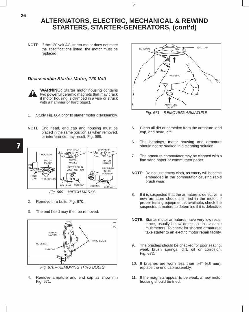
26
7
ALTERNATORS, ELECTRIC, MECHANICAL & REWINDSTARTERS, STARTER-GENERATORS, (cont’d)
NOTE: If the 120 volt AC starter motor does not meetthe specifications listed, the motor must bereplaced.
Disassemble Starter Motor, 120 Volt
WARNING: Starter motor housing containstwo powerful ceramic magnets that may crackif motor housing is clamped in a vise or struckwith a hammer or hard object.
1. Study Fig. 664 prior to starter motor disassembly.
NOTE: End head, end cap and housing must beplaced in the same position as when removed,or interference may result, Fig. 669.
HOUSING
MATCHMARKS
ENDCAP THRU BOLTS
END HEAD END HEAD
MATCHMARKS
MATCHMARKS
RECTIFIER INLOW POSITION
HOUSING END CAP
RECTIFIERIN HIGH
POSITION
HOUSING END CAP
Fig. 669 – MATCH MARKS
2. Remove thru bolts, Fig. 670.
3. The end head may then be removed.
END CAP
HOUSING
MATCHMARKS
THRU BOLTS
Fig. 670 – REMOVING THRU BOLTS
4. Remove armature and end cap as shown inFig. 671.
TERMINAL
ARMATURESHAFT
HOUSING
END CAP
Fig. 671 – REMOVING ARMATURE
5. Clean all dirt or corrosion from the armature, endcap, end head, etc.
6. The bearings, motor housing and armatureshould not be soaked in a cleaning solution.
7. The armature commutator may be cleaned with afine sand paper or commutator paper.
NOTE: Do not use emery cloth, as emery will becomeembedded in the commutator causing rapidbrush wear.
8. If it is suspected that the armature is defective, anew armature should be tried in the motor. Ifproper testing equipment is available, check thesuspected armature to determine if it is defective.
NOTE: Starter motor armatures have very low resis-tance, usually below detection on availablemultimeters. To check for shorted armatures,take starter to an electric motor repair facility.
9. The brushes should be checked for poor seating,weak brush springs, dirt, oil or corrosion,Fig. 672.
10. If brushes are worn less than ,replace the end cap assembly.
11. If the magnets appear to be weak, a new motorhousing should be tried.
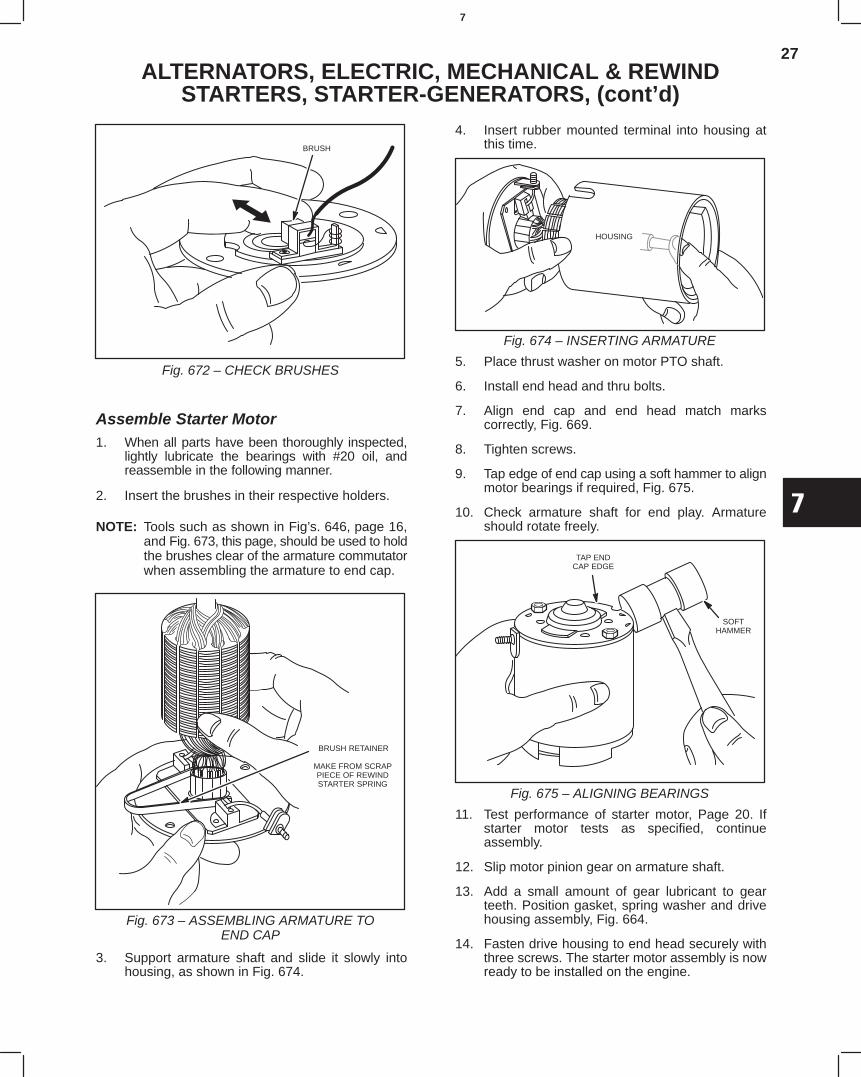
27
7
ALTERNATORS, ELECTRIC, MECHANICAL & REWINDSTARTERS, STARTER-GENERATORS, (cont’d)
BRUSH
Fig. 672 – CHECK BRUSHES
Assemble Starter Motor1. When all parts have been thoroughly inspected,
lightly lubricate the bearings with #20 oil, andreassemble in the following manner.
2. Insert the brushes in their respective holders.
NOTE: Tools such as shown in Fig’s. 646, page 16,and Fig. 673, this page, should be used to holdthe brushes clear of the armature commutatorwhen assembling the armature to end cap.
BRUSH RETAINER
MAKE FROM SCRAPPIECE OF REWINDSTARTER SPRING
Fig. 673 – ASSEMBLING ARMATURE TOEND CAP
3. Support armature shaft and slide it slowly intohousing, as shown in Fig. 674.
4. Insert rubber mounted terminal into housing atthis time.
HOUSING
Fig. 674 – INSERTING ARMATURE
5. Place thrust washer on motor PTO shaft.
6. Install end head and thru bolts.
7. Align end cap and end head match markscorrectly, Fig. 669.
8. Tighten screws.
9. Tap edge of end cap using a soft hammer to alignmotor bearings if required, Fig. 675.
10. Check armature shaft for end play. Armatureshould rotate freely.
TAP ENDCAP EDGE
SOFTHAMMER
Fig. 675 – ALIGNING BEARINGS
11. Test performance of starter motor, Page 20. Ifstarter motor tests as specified, continueassembly.
12. Slip motor pinion gear on armature shaft.
13. Add a small amount of gear lubricant to gearteeth. Position gasket, spring washer and drivehousing assembly, Fig. 664.
14. Fasten drive housing to end head securely withthree screws. The starter motor assembly is nowready to be installed on the engine.
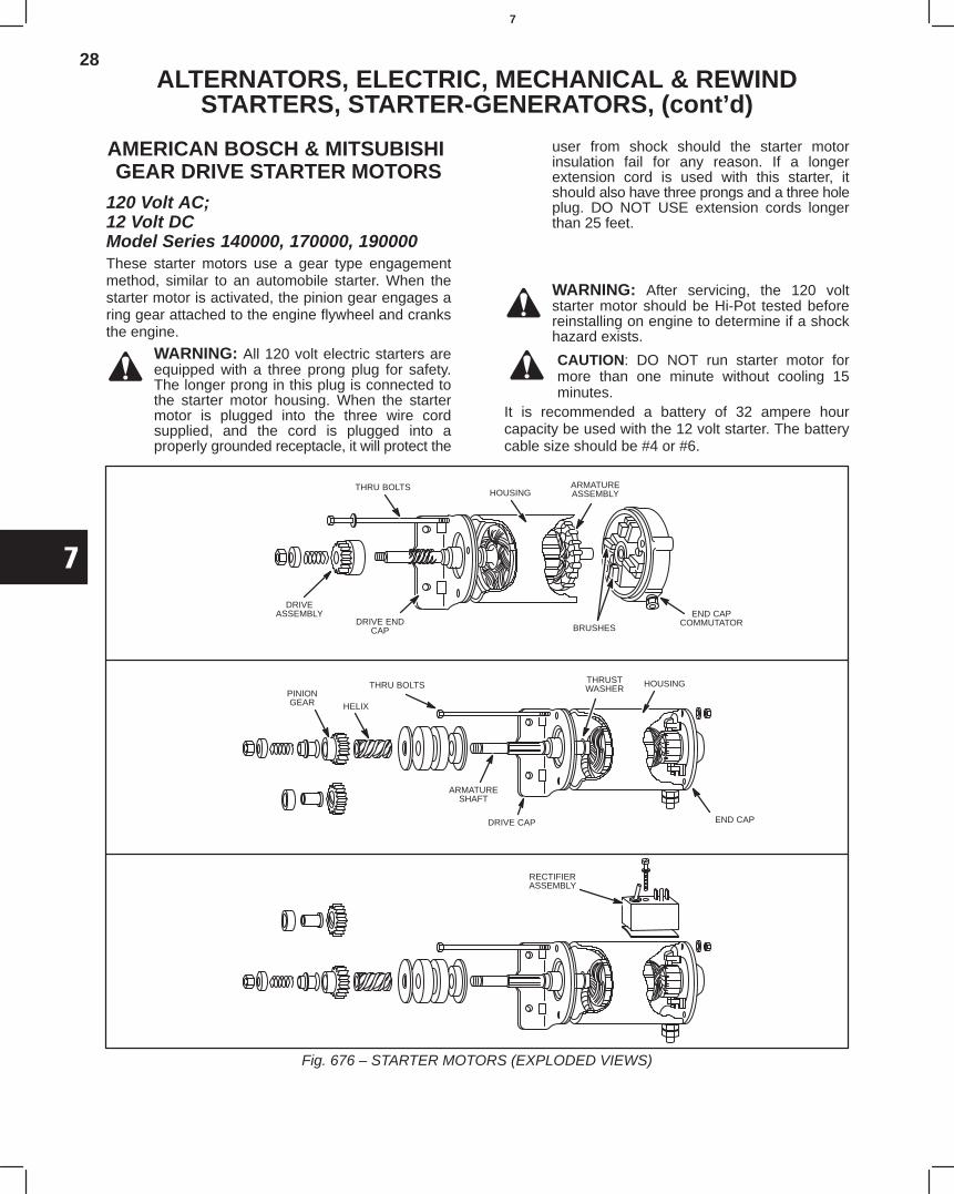
28
7
ALTERNATORS, ELECTRIC, MECHANICAL & REWINDSTARTERS, STARTER-GENERATORS, (cont’d)
AMERICAN BOSCH & MITSUBISHI GEAR DRIVE STARTER MOTORS
120 Volt AC; 12 Volt DCModel Series 140000, 170000, 190000These starter motors use a gear type engagementmethod, similar to an automobile starter. When thestarter motor is activated, the pinion gear engages aring gear attached to the engine flywheel and cranksthe engine.
WARNING: All 120 volt electric starters areequipped with a three prong plug for safety.The longer prong in this plug is connected tothe starter motor housing. When the startermotor is plugged into the three wire cordsupplied, and the cord is plugged into aproperly grounded receptacle, it will protect the
user from shock should the starter motorinsulation fail for any reason. If a longerextension cord is used with this starter, itshould also have three prongs and a three holeplug. DO NOT USE extension cords longerthan 25 feet.
WARNING: After servicing, the 120 voltstarter motor should be Hi-Pot tested beforereinstalling on engine to determine if a shockhazard exists.
CAUTION: DO NOT run starter motor formore than one minute without cooling 15minutes.
It is recommended a battery of 32 ampere hourcapacity be used with the 12 volt starter. The batterycable size should be #4 or #6.
Fig. 676 – STARTER MOTORS (EXPLODED VIEWS)
BRUSHES
END CAPCOMMUTATOR
ARMATUREASSEMBLYHOUSING
THRU BOLTS
DRIVEASSEMBLY
DRIVE ENDCAP
THRU BOLTSPINIONGEAR HELIX
ARMATURESHAFT
DRIVE CAP
HOUSING
END CAP
RECTIFIERASSEMBLY
THRUSTWASHER
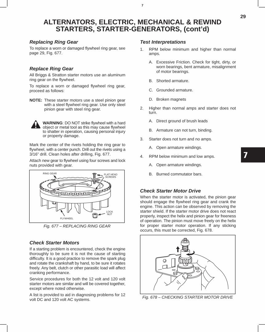
29
7
ALTERNATORS, ELECTRIC, MECHANICAL & REWINDSTARTERS, STARTER-GENERATORS, (cont’d)
Replacing Ring GearTo replace a worn or damaged flywheel ring gear, seepage 29, Fig. 677.
Replace Ring GearAll Briggs & Stratton starter motors use an aluminumring gear on the flywheel.
To replace a worn or damaged flywheel ring gear,proceed as follows:
NOTE: These starter motors use a steel pinion gearwith a steel flywheel ring gear. Use only steelpinion gear with steel ring gear.
WARNING: DO NOT strike flywheel with a hardobject or metal tool as this may cause flywheelto shatter in operation, causing personal injuryor property damage.
Mark the center of the rivets holding the ring gear toflywheel, with a center punch. Drill out the rivets using a3/16” drill. Clean holes after drilling, Fig. 677.
Attach new gear to flywheel using four screws and locknuts provided with gear.
Fig. 677 – REPLACING RING GEAR
RING GEAR FLAT HEADSCREWS
LOCKNUT
FLYWHEEL
Check Starter MotorsIf a starting problem is encountered, check the enginethoroughly to be sure it is not the cause of startingdifficulty. It is a good practice to remove the spark plugand rotate the crankshaft by hand, to be sure it rotatesfreely. Any belt, clutch or other parasitic load will affectcranking performance.
Service procedures for both the 12 volt and 120 voltstarter motors are similar and will be covered together,except where noted otherwise.
A list is provided to aid in diagnosing problems for 12volt DC and 120 volt AC systems.
Test Interpretations1. RPM below minimum and higher than normal
amps.
A. Excessive Friction. Check for tight, dirty, orworn bearings, bent armature, misalignmentof motor bearings.
B. Shorted armature.
C. Grounded armature.
D. Broken magnets
2. Higher than normal amps and starter does notturn.
A. Direct ground of brush leads
B. Armature can not turn, binding.
3. Starter does not turn and no amps.
A. Open armature windings.
4. RPM below minimum and low amps.
A. Open armature windings.
B. Burned commutator bars.
Check Starter Motor DriveWhen the starter motor is activated, the pinion gearshould engage the flywheel ring gear and crank theengine. This action can be observed by removing thestarter shield. If the starter motor drive does not reactproperly, inspect the helix and pinion gear for freenessof operation. The pinion must move freely on the helixfor proper starter motor operation. If any stickingoccurs, this must be corrected, Fig. 678.
Fig. 678 – CHECKING STARTER MOTOR DRIVE
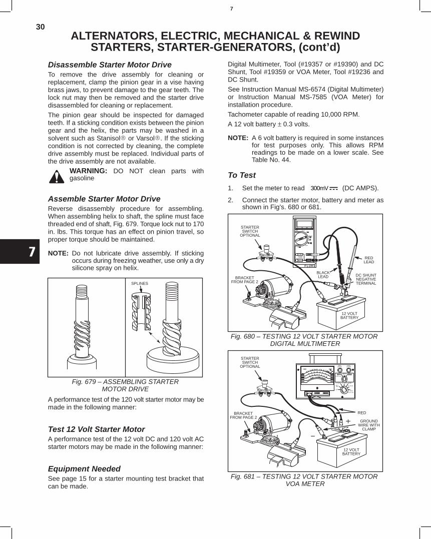
30
7
ALTERNATORS, ELECTRIC, MECHANICAL & REWINDSTARTERS, STARTER-GENERATORS, (cont’d)
Disassemble Starter Motor DriveTo remove the drive assembly for cleaning orreplacement, clamp the pinion gear in a vise havingbrass jaws, to prevent damage to the gear teeth. Thelock nut may then be removed and the starter drivedisassembled for cleaning or replacement.
The pinion gear should be inspected for damagedteeth. If a sticking condition exists between the piniongear and the helix, the parts may be washed in asolvent such as Stanisol or Varsol. If the stickingcondition is not corrected by cleaning, the completedrive assembly must be replaced. Individual parts ofthe drive assembly are not available.
WARNING: DO NOT clean parts withgasoline
Assemble Starter Motor DriveReverse disassembly procedure for assembling.When assembling helix to shaft, the spline must facethreaded end of shaft, Fig. 679. Torque lock nut to 170in. lbs. This torque has an effect on pinion travel, soproper torque should be maintained.
NOTE: Do not lubricate drive assembly. If stickingoccurs during freezing weather, use only a drysilicone spray on helix.
Fig. 679 – ASSEMBLING STARTERMOTOR DRIVE
SPLINES
A performance test of the 120 volt starter motor may bemade in the following manner:
Test 12 Volt Starter MotorA performance test of the 12 volt DC and 120 volt ACstarter motors may be made in the following manner:
Equipment NeededSee page 15 for a starter mounting test bracket thatcan be made.
Digital Multimeter, Tool (#19357 or #19390) and DCShunt, Tool #19359 or VOA Meter, Tool #19236 andDC Shunt.
See Instruction Manual MS-6574 (Digital Multimeter)or Instruction Manual MS-7585 (VOA Meter) forinstallation procedure.
Tachometer capable of reading 10,000 RPM.
A 12 volt battery ± 0.3 volts.
NOTE: A 6 volt battery is required in some instancesfor test purposes only. This allows RPMreadings to be made on a lower scale. SeeTable No. 44.
To Test
1. Set the meter to read 300mV (DC AMPS).
2. Connect the starter motor, battery and meter asshown in Fig’s. 680 or 681.
Fig. 680 – TESTING 12 VOLT STARTER MOTOR DIGITAL MULTIMETER
REDLEAD
BLACKLEAD DC SHUNT
NEGATIVETERMINAL
12 VOLTBATTERY
STARTERSWITCH
OPTIONAL
BRACKETFROM PAGE 2
Fig. 681 – TESTING 12 VOLT STARTER MOTOR VOA METER
STARTERSWITCH
OPTIONAL
BRACKETFROM PAGE 2
RED
12 VOLTBATTERY
GROUNDWIRE WITH
CLAMP
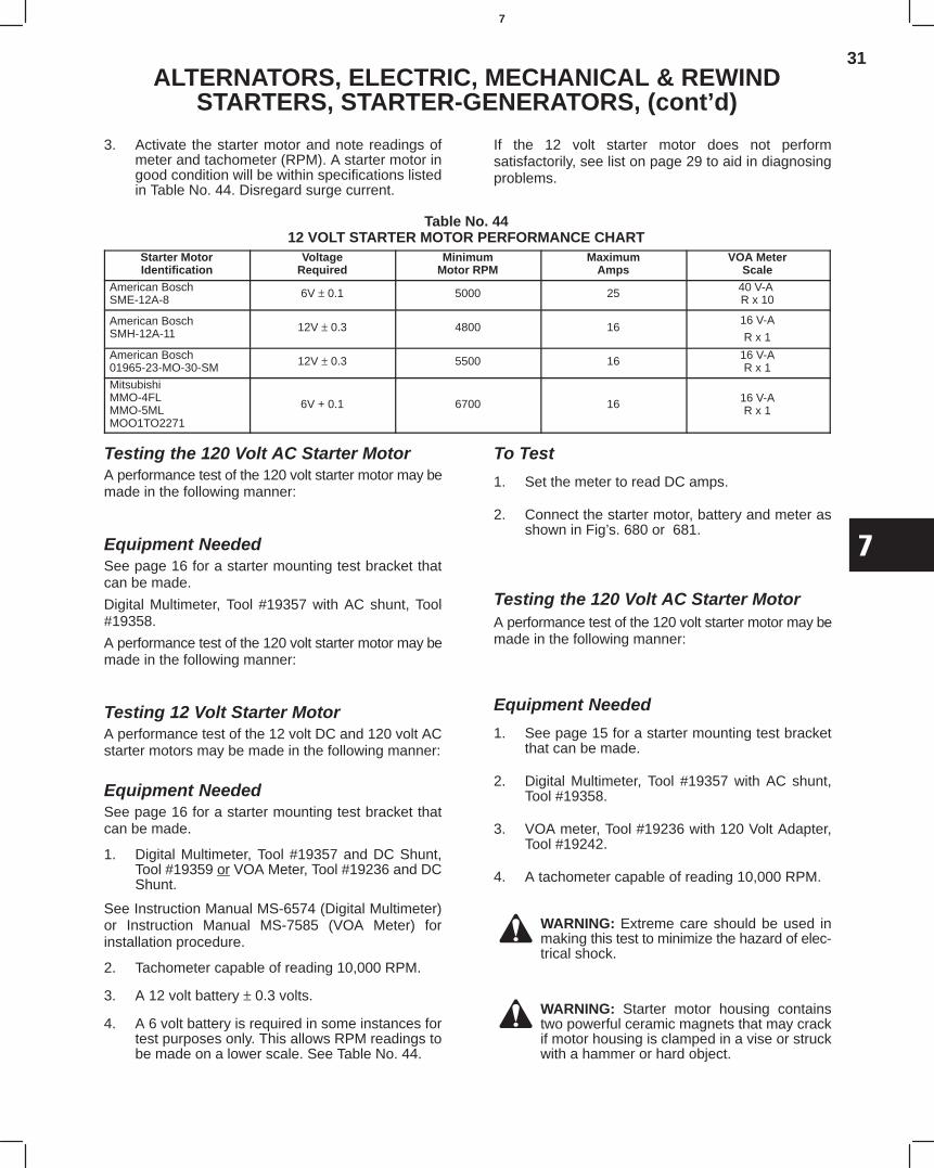
31
7
ALTERNATORS, ELECTRIC, MECHANICAL & REWINDSTARTERS, STARTER-GENERATORS, (cont’d)
3. Activate the starter motor and note readings ofmeter and tachometer (RPM). A starter motor ingood condition will be within specifications listedin Table No. 44. Disregard surge current.
If the 12 volt starter motor does not performsatisfactorily, see list on page 29 to aid in diagnosingproblems.
Table No. 4412 VOLT STARTER MOTOR PERFORMANCE CHART
Starter MotorIdentification
VoltageRequired
MinimumMotor RPM
MaximumAmps
VOA MeterScale
American BoschSME-12A-8 6V ± 0.1 5000 25 40 V-A
R x 10
American BoschSMH-12A-11 12V ± 0.3 4800 16
16 V-A
R x 1
American Bosch01965-23-MO-30-SM 12V ± 0.3 5500 16 16 V-A
R x 1
MitsubishiMMO-4FLMMO-5MLMOO1TO2271
6V + 0.1 6700 16 16 V-AR x 1
Testing the 120 Volt AC Starter MotorA performance test of the 120 volt starter motor may bemade in the following manner:
Equipment NeededSee page 16 for a starter mounting test bracket thatcan be made.
Digital Multimeter, Tool #19357 with AC shunt, Tool#19358.
A performance test of the 120 volt starter motor may bemade in the following manner:
Testing 12 Volt Starter MotorA performance test of the 12 volt DC and 120 volt ACstarter motors may be made in the following manner:
Equipment NeededSee page 16 for a starter mounting test bracket thatcan be made.
1. Digital Multimeter, Tool #19357 and DC Shunt,Tool #19359 or VOA Meter, Tool #19236 and DCShunt.
See Instruction Manual MS-6574 (Digital Multimeter)or Instruction Manual MS-7585 (VOA Meter) forinstallation procedure.
2. Tachometer capable of reading 10,000 RPM.
3. A 12 volt battery ± 0.3 volts.
4. A 6 volt battery is required in some instances fortest purposes only. This allows RPM readings tobe made on a lower scale. See Table No. 44.
To Test
1. Set the meter to read DC amps.
2. Connect the starter motor, battery and meter asshown in Fig’s. 680 or 681.
Testing the 120 Volt AC Starter MotorA performance test of the 120 volt starter motor may bemade in the following manner:
Equipment Needed
1. See page 15 for a starter mounting test bracketthat can be made.
2. Digital Multimeter, Tool #19357 with AC shunt,Tool #19358.
3. VOA meter, Tool #19236 with 120 Volt Adapter,Tool #19242.
4. A tachometer capable of reading 10,000 RPM.
WARNING: Extreme care should be used inmaking this test to minimize the hazard of elec-trical shock.
WARNING: Starter motor housing containstwo powerful ceramic magnets that may crackif motor housing is clamped in a vise or struckwith a hammer or hard object.
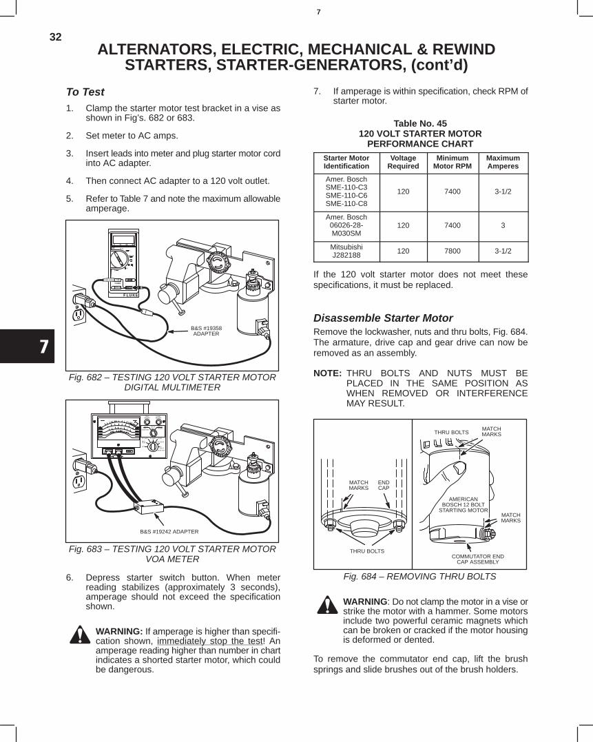
32
7
ALTERNATORS, ELECTRIC, MECHANICAL & REWINDSTARTERS, STARTER-GENERATORS, (cont’d)
To Test1. Clamp the starter motor test bracket in a vise as
shown in Fig’s. 682 or 683.
2. Set meter to AC amps.
3. Insert leads into meter and plug starter motor cordinto AC adapter.
4. Then connect AC adapter to a 120 volt outlet.
5. Refer to Table 7 and note the maximum allowableamperage.
Fig. 682 – TESTING 120 VOLT STARTER MOTORDIGITAL MULTIMETER
B&S #19358ADAPTER
Fig. 683 – TESTING 120 VOLT STARTER MOTORVOA METER
B&S #19242 ADAPTER
6. Depress starter switch button. When meterreading stabilizes (approximately 3 seconds),amperage should not exceed the specificationshown.
WARNING: If amperage is higher than specifi-cation shown, immediately stop the test! Anamperage reading higher than number in chartindicates a shorted starter motor, which couldbe dangerous.
7. If amperage is within specification, check RPM ofstarter motor.
Table No. 45120 VOLT STARTER MOTOR
PERFORMANCE CHARTStarter MotorIdentification
VoltageRequired
MinimumMotor RPM
MaximumAmperes
Amer. BoschSME-110-C3SME-110-C6SME-110-C8
120 7400 3-1/2
Amer. Bosch06026-28-M030SM
120 7400 3
MitsubishiJ282188 120 7800 3-1/2
If the 120 volt starter motor does not meet thesespecifications, it must be replaced.
Disassemble Starter MotorRemove the lockwasher, nuts and thru bolts, Fig. 684.The armature, drive cap and gear drive can now beremoved as an assembly.
NOTE: THRU BOLTS AND NUTS MUST BEPLACED IN THE SAME POSITION ASWHEN REMOVED OR INTERFERENCEMAY RESULT.
Fig. 684 – REMOVING THRU BOLTS
THRU BOLTSMATCHMARKS
AMERICANBOSCH 12 BOLT
STARTING MOTOR
ENDCAP
COMMUTATOR ENDCAP ASSEMBLY
MATCHMARKS
MATCHMARKS
THRU BOLTS
WARNING: Do not clamp the motor in a vise orstrike the motor with a hammer. Some motorsinclude two powerful ceramic magnets whichcan be broken or cracked if the motor housingis deformed or dented.
To remove the commutator end cap, lift the brushsprings and slide brushes out of the brush holders.
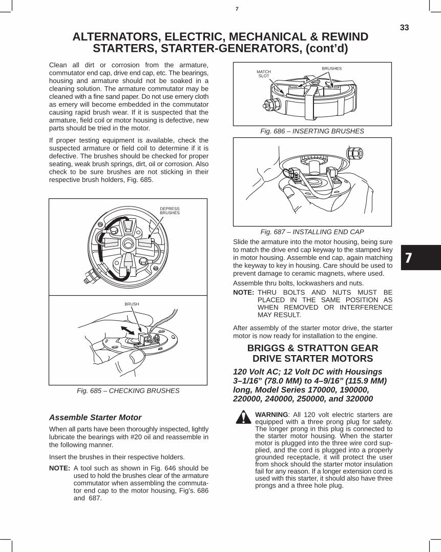
33
7
ALTERNATORS, ELECTRIC, MECHANICAL & REWINDSTARTERS, STARTER-GENERATORS, (cont’d)
Clean all dirt or corrosion from the armature,commutator end cap, drive end cap, etc. The bearings,housing and armature should not be soaked in acleaning solution. The armature commutator may becleaned with a fine sand paper. Do not use emery clothas emery will become embedded in the commutatorcausing rapid brush wear. If it is suspected that thearmature, field coil or motor housing is defective, newparts should be tried in the motor.
If proper testing equipment is available, check thesuspected armature or field coil to determine if it isdefective. The brushes should be checked for properseating, weak brush springs, dirt, oil or corrosion. Alsocheck to be sure brushes are not sticking in theirrespective brush holders, Fig. 685.
Fig. 685 – CHECKING BRUSHES
BRUSH
DEPRESSBRUSHES
Assemble Starter MotorWhen all parts have been thoroughly inspected, lightlylubricate the bearings with #20 oil and reassemble inthe following manner.
Insert the brushes in their respective holders.
NOTE: A tool such as shown in Fig. 646 should beused to hold the brushes clear of the armaturecommutator when assembling the commuta-tor end cap to the motor housing, Fig’s. 686and 687.
Fig. 686 – INSERTING BRUSHES
BRUSHESMATCHSLOT
Fig. 687 – INSTALLING END CAP
Slide the armature into the motor housing, being sureto match the drive end cap keyway to the stamped keyin motor housing. Assemble end cap, again matchingthe keyway to key in housing. Care should be used toprevent damage to ceramic magnets, where used.Assemble thru bolts, lockwashers and nuts.NOTE: THRU BOLTS AND NUTS MUST BE
PLACED IN THE SAME POSITION ASWHEN REMOVED OR INTERFERENCEMAY RESULT.
After assembly of the starter motor drive, the startermotor is now ready for installation to the engine.
BRIGGS & STRATTON GEARDRIVE STARTER MOTORS
120 Volt AC; 12 Volt DC with Housings3–1/16” (78.0 MM) to 4–9/16”(115.9 MM)long, Model Series 170000, 190000,220000, 240000, 250000, and 320000
WARNING: All 120 volt electric starters areequipped with a three prong plug for safety.The longer prong in this plug is connected tothe starter motor housing. When the startermotor is plugged into the three wire cord sup-plied, and the cord is plugged into a properlygrounded receptacle, it will protect the userfrom shock should the starter motor insulationfail for any reason. If a longer extension cord isused with this starter, it should also have threeprongs and a three hole plug.
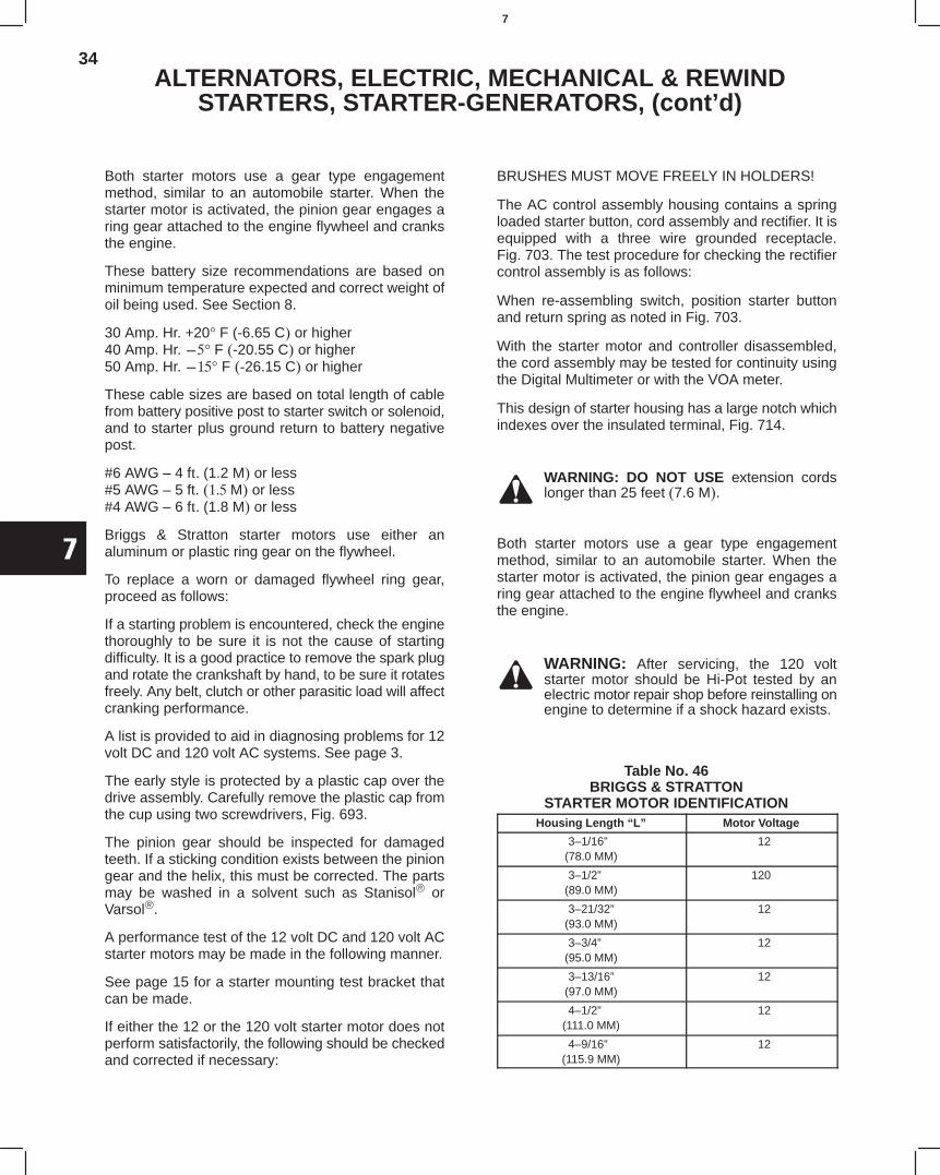
34
7
ALTERNATORS, ELECTRIC, MECHANICAL & REWINDSTARTERS, STARTER-GENERATORS, (cont’d)
Both starter motors use a gear type engagementmethod, similar to an automobile starter. When thestarter motor is activated, the pinion gear engages aring gear attached to the engine flywheel and cranksthe engine.
These battery size recommendations are based onminimum temperature expected and correct weight ofoil being used. See Section 8.
30 Amp. Hr. +20° F (-6.65 C or higher40 Amp. Hr. ° F -20.55 C or higher50 Amp. Hr. ° F 26.15 C or higher
These cable sizes are based on total length of cablefrom battery positive post to starter switch or solenoid,and to starter plus ground return to battery negativepost.
#6 AWG – 4 f (1.2 M or less#5 AWG – 5 ft. M or less#4 AWG – 6 f (1.8 M or less
Briggs & Stratton starter motors use either analuminum or plastic ring gear on the flywheel.
To replace a worn or damaged flywheel ring gear,proceed as follows:
If a starting problem is encountered, check the enginethoroughly to be sure it is not the cause of startingdifficulty. It is a good practice to remove the spark plugand rotate the crankshaft by hand, to be sure it rotatesfreely. Any belt, clutch or other parasitic load will affectcranking performance.
A list is provided to aid in diagnosing problems for 12volt DC and 120 volt AC systems. See page 3.
The early style is protected by a plastic cap over thedrive assembly. Carefully remove the plastic cap fromthe cup using two screwdrivers, Fig. 693.
The pinion gear should be inspected for damagedteeth. If a sticking condition exists between the piniongear and the helix, this must be corrected. The partsmay be washed in a solvent such as Stanisol orVarsol.
A performance test of the 12 volt DC and 120 volt ACstarter motors may be made in the following manner.
See page 15 for a starter mounting test bracket thatcan be made.
If either the 12 or the 120 volt starter motor does notperform satisfactorily, the following should be checkedand corrected if necessary:
BRUSHES MUST MOVE FREELY IN HOLDERS!
The AC control assembly housing contains a springloaded starter button, cord assembly and rectifier. It isequipped with a three wire grounded receptacle.Fig. 703. The test procedure for checking the rectifiercontrol assembly is as follows:
When re-assembling switch, position starter buttonand return spring as noted in Fig. 703.
With the starter motor and controller disassembled,the cord assembly may be tested for continuity usingthe Digital Multimeter or with the VOA meter.
This design of starter housing has a large notch whichindexes over the insulated terminal, Fig. 714.
WARNING: DO NOT USE extension cordslonger than 25 feet7.6 M.
Both starter motors use a gear type engagementmethod, similar to an automobile starter. When thestarter motor is activated, the pinion gear engages aring gear attached to the engine flywheel and cranksthe engine.
WARNING: After servicing, the 120 voltstarter motor should be Hi-Pot tested by anelectric motor repair shop before reinstalling onengine to determine if a shock hazard exists.
Table No. 46BRIGGS & STRATTON
STARTER MOTOR IDENTIFICATIONHousing Length “L” Motor Voltage
3–1/16”(78.0 MM)
12
3–1/2”(89.0 MM)
120
3–21/32”(93.0 MM)
12
3–3/4”(95.0 MM)
12
3–13/16”(97.0 MM)
12
4–1/2”(111.0 MM)
12
4–9/16”(115.9 MM)
12
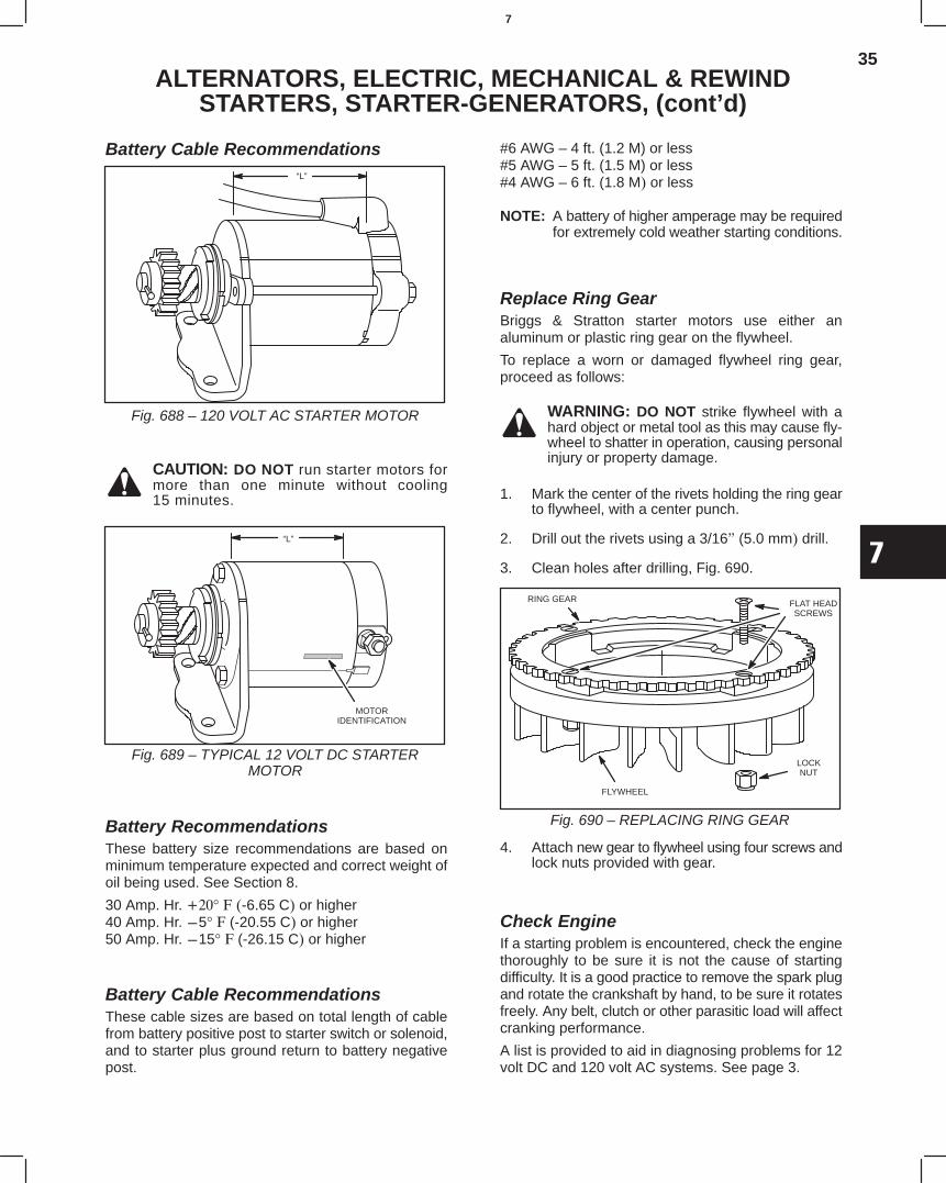
35
7
ALTERNATORS, ELECTRIC, MECHANICAL & REWINDSTARTERS, STARTER-GENERATORS, (cont’d)
Battery Cable Recommendations“L”
Fig. 688 – 120 VOLT AC STARTER MOTOR
CAUTION: DO NOT run starter motors formore than one minute without cooling15 minutes.
“L”
MOTORIDENTIFICATION
Fig. 689 – TYPICAL 12 VOLT DC STARTERMOTOR
Battery RecommendationsThese battery size recommendations are based onminimum temperature expected and correct weight ofoil being used. See Section 8.
30 Amp. Hr. ° -6.65 C or higher40 Amp. Hr. 5° (-20.55 C or higher50 Amp. Hr. 15° (-26.15 C or higher
Battery Cable RecommendationsThese cable sizes are based on total length of cablefrom battery positive post to starter switch or solenoid,and to starter plus ground return to battery negativepost.
#6 AWG – 4 ft. (1.2 M) or less#5 AWG – 5 ft. (1.5 M) or less#4 AWG – 6 ft. (1.8 M or less
NOTE: A battery of higher amperage may be requiredfor extremely cold weather starting conditions.
Replace Ring GearBriggs & Stratton starter motors use either analuminum or plastic ring gear on the flywheel.
To replace a worn or damaged flywheel ring gear,proceed as follows:
WARNING: DO NOT strike flywheel with ahard object or metal tool as this may cause fly-wheel to shatter in operation, causing personalinjury or property damage.
1. Mark the center of the rivets holding the ring gearto flywheel, with a center punch.
2. Drill out the rivets using a 3/16 (5.0 mm drill.
3. Clean holes after drilling, Fig. 690.
RING GEAR FLAT HEADSCREWS
LOCKNUT
FLYWHEEL
Fig. 690 – REPLACING RING GEAR
4. Attach new gear to flywheel using four screws andlock nuts provided with gear.
Check EngineIf a starting problem is encountered, check the enginethoroughly to be sure it is not the cause of startingdifficulty. It is a good practice to remove the spark plugand rotate the crankshaft by hand, to be sure it rotatesfreely. Any belt, clutch or other parasitic load will affectcranking performance.
A list is provided to aid in diagnosing problems for 12volt DC and 120 volt AC systems. See page 3.
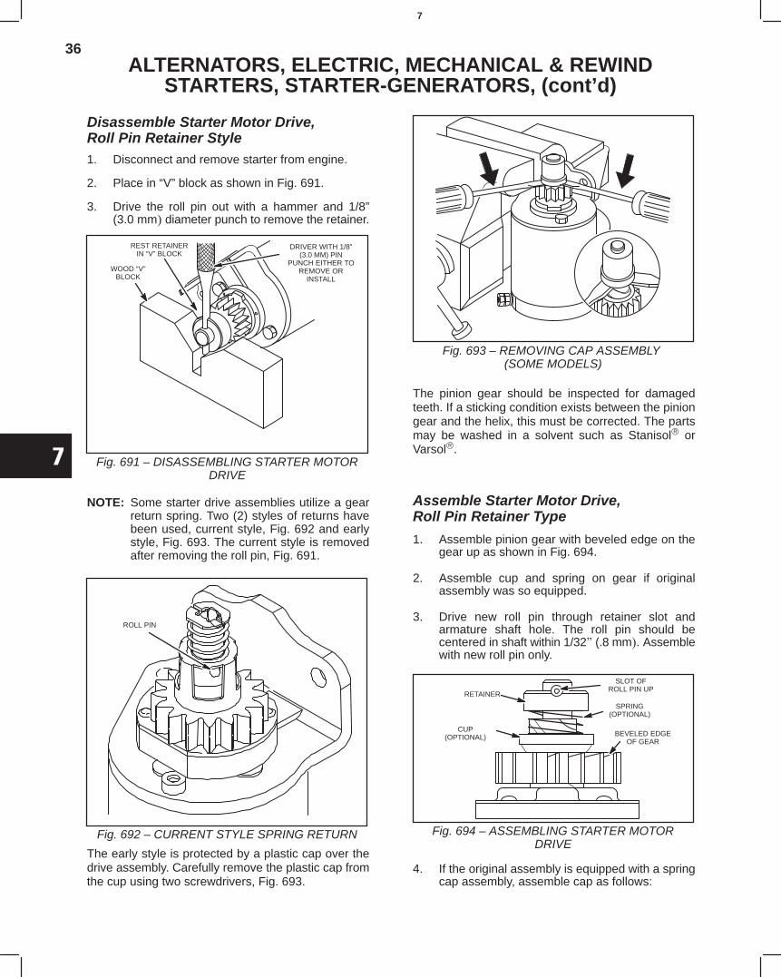
36
7
ALTERNATORS, ELECTRIC, MECHANICAL & REWINDSTARTERS, STARTER-GENERATORS, (cont’d)
Disassemble Starter Motor Drive,Roll Pin Retainer Style1. Disconnect and remove starter from engine.
2. Place in “V” block as shown in Fig. 691.
3. Drive the roll pin out with a hammer and 1/8”(3.0 mm diameter punch to remove the retainer.
WOOD “V”BLOCK
REST RETAINERIN “V” BLOCK
DRIVER WITH 1/8”(3.0 MM) PIN
PUNCH EITHER TOREMOVE OR
INSTALL
Fig. 691 – DISASSEMBLING STARTER MOTORDRIVE
NOTE: Some starter drive assemblies utilize a gearreturn spring. Two (2) styles of returns havebeen used, current style, Fig. 692 and earlystyle, Fig. 693. The current style is removedafter removing the roll pin, Fig. 691.
Fig. 692 – CURRENT STYLE SPRING RETURN
ROLL PIN
The early style is protected by a plastic cap over thedrive assembly. Carefully remove the plastic cap fromthe cup using two screwdrivers, Fig. 693.
Fig. 693 – REMOVING CAP ASSEMBLY (SOME MODELS)
The pinion gear should be inspected for damagedteeth. If a sticking condition exists between the piniongear and the helix, this must be corrected. The partsmay be washed in a solvent such as Stanisol orVarsol.
Assemble Starter Motor Drive,Roll Pin Retainer Type
1. Assemble pinion gear with beveled edge on thegear up as shown in Fig. 694.
2. Assemble cup and spring on gear if originalassembly was so equipped.
3. Drive new roll pin through retainer slot andarmature shaft hole. The roll pin should becentered in shaft within 1/32 (.8 mm. Assemblewith new roll pin only.
SLOT OFROLL PIN UP
RETAINER
SPRING(OPTIONAL)
CUP(OPTIONAL) BEVELED EDGE
OF GEAR
Fig. 694 – ASSEMBLING STARTER MOTORDRIVE
4. If the original assembly is equipped with a springcap assembly, assemble cap as follows:
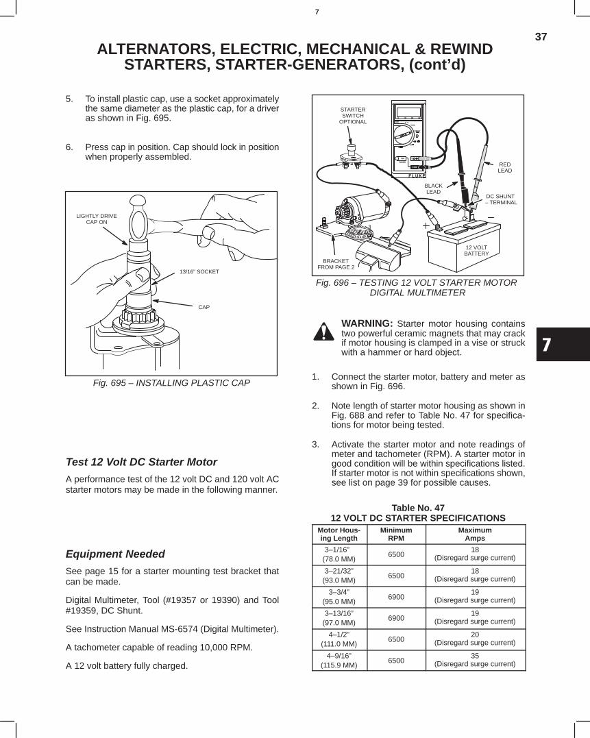
37
7
ALTERNATORS, ELECTRIC, MECHANICAL & REWINDSTARTERS, STARTER-GENERATORS, (cont’d)
5. To install plastic cap, use a socket approximatelythe same diameter as the plastic cap, for a driveras shown in Fig. 695.
6. Press cap in position. Cap should lock in positionwhen properly assembled.
LIGHTLY DRIVECAP ON
13/16” SOCKET
CAP
Fig. 695 – INSTALLING PLASTIC CAP
Test 12 Volt DC Starter Motor
A performance test of the 12 volt DC and 120 volt ACstarter motors may be made in the following manner.
Equipment Needed
See page 15 for a starter mounting test bracket thatcan be made.
Digital Multimeter, Tool (#19357 or 19390) and Tool#19359, DC Shunt.
See Instruction Manual MS-6574 (Digital Multimeter).
A tachometer capable of reading 10,000 RPM.
A 12 volt battery fully charged.
REDLEAD
BLACKLEAD
DC SHUNT – TERMINAL
12 VOLTBATTERY
STARTERSWITCH
OPTIONAL
BRACKETFROM PAGE 2
Fig. 696 – TESTING 12 VOLT STARTER MOTOR DIGITAL MULTIMETER
WARNING: Starter motor housing containstwo powerful ceramic magnets that may crackif motor housing is clamped in a vise or struckwith a hammer or hard object.
1. Connect the starter motor, battery and meter asshown in Fig. 696.
2. Note length of starter motor housing as shown inFig. 688 and refer to Table No. 47 for specifica-tions for motor being tested.
3. Activate the starter motor and note readings ofmeter and tachometer (RPM). A starter motor ingood condition will be within specifications listed.If starter motor is not within specifications shown,see list on page 39 for possible causes.
Table No. 4712 VOLT DC STARTER SPECIFICATIONS
Motor Hous-ing Length
MinimumRPM
MaximumAmps
3–1/16”(78.0 MM)
650018
(Disregard surge current)
3–21/32”(93.0 MM)
650018
(Disregard surge current)
3–3/4”(95.0 MM)
690019
(Disregard surge current)
3–13/16”(97.0 MM)
690019
(Disregard surge current)
4–1/2”(111.0 MM)
650020
(Disregard surge current)
4–9/16”(115.9 MM)
650035
(Disregard surge current)
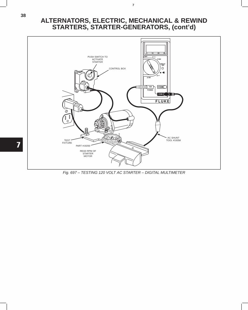
38
7
ALTERNATORS, ELECTRIC, MECHANICAL & REWINDSTARTERS, STARTER-GENERATORS, (cont’d)
PUSH SWITCH TOACTIVATESTARTER
CONTROL BOX
TESTFIXTURE
PART #19200
READ RPM OFSTARTERMOTOR
AC SHUNTTOOL #19358
Fig. 697 – TESTING 120 VOLT AC STARTER – DIGITAL MULTIMETER
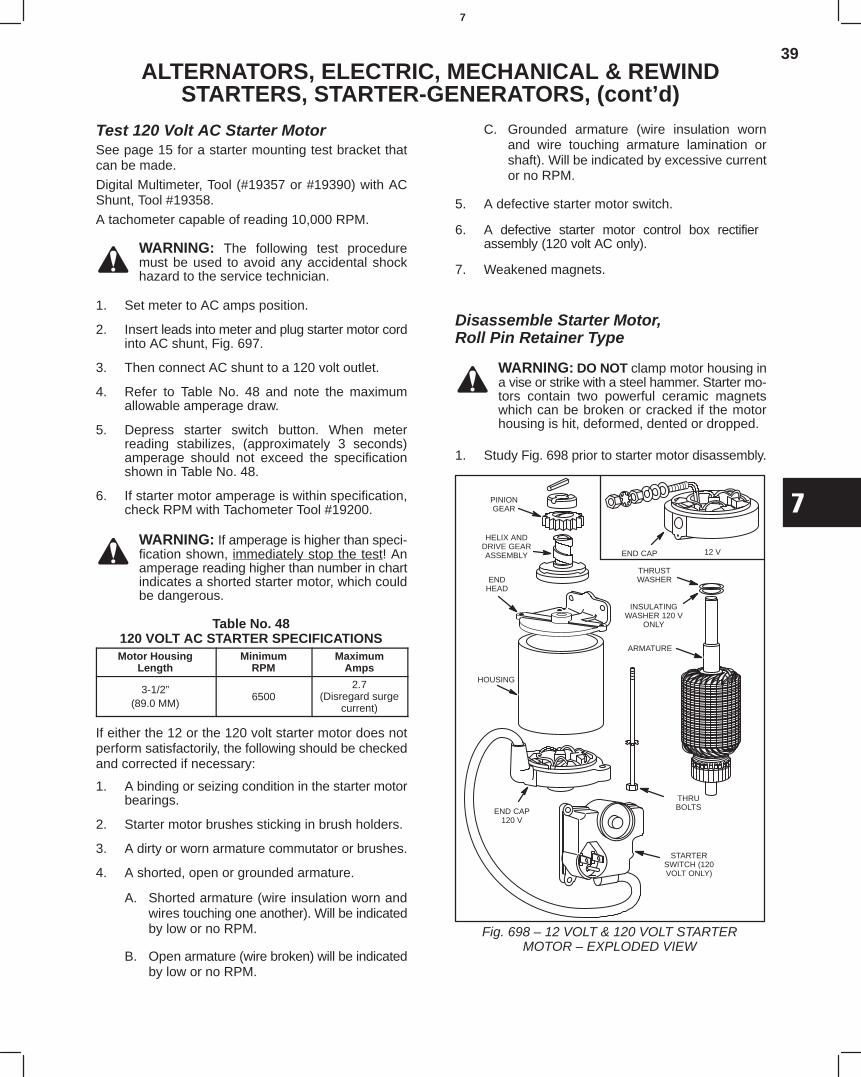
39
7
ALTERNATORS, ELECTRIC, MECHANICAL & REWINDSTARTERS, STARTER-GENERATORS, (cont’d)
Test 120 Volt AC Starter MotorSee page 15 for a starter mounting test bracket thatcan be made.
Digital Multimeter, Tool (#19357 or #19390) with ACShunt, Tool #19358.
A tachometer capable of reading 10,000 RPM.
WARNING: The following test proceduremust be used to avoid any accidental shockhazard to the service technician.
1. Set meter to AC amps position.
2. Insert leads into meter and plug starter motor cordinto AC shunt, Fig. 697.
3. Then connect AC shunt to a 120 volt outlet.
4. Refer to Table No. 48 and note the maximumallowable amperage draw.
5. Depress starter switch button. When meterreading stabilizes, (approximately 3 seconds)amperage should not exceed the specificationshown in Table No. 48.
6. If starter motor amperage is within specification,check RPM with Tachometer Tool #19200.
WARNING: If amperage is higher than speci-fication shown, immediately stop the test! Anamperage reading higher than number in chartindicates a shorted starter motor, which couldbe dangerous.
Table No. 48120 VOLT AC STARTER SPECIFICATIONSMotor Housing
LengthMinimum
RPMMaximum
Amps
3-1/2”(89.0 MM)
65002.7
(Disregard surgecurrent)
If either the 12 or the 120 volt starter motor does notperform satisfactorily, the following should be checkedand corrected if necessary:
1. A binding or seizing condition in the starter motorbearings.
2. Starter motor brushes sticking in brush holders.
3. A dirty or worn armature commutator or brushes.
4. A shorted, open or grounded armature.
A. Shorted armature (wire insulation worn andwires touching one another). Will be indicatedby low or no RPM.
B. Open armature (wire broken) will be indicatedby low or no RPM.
C. Grounded armature (wire insulation wornand wire touching armature lamination orshaft). Will be indicated by excessive currentor no RPM.
5. A defective starter motor switch.
6. A defective starter motor control box rectifier assembly (120 volt AC only).
7. Weakened magnets.
Disassemble Starter Motor,Roll Pin Retainer Type
WARNING: DO NOT clamp motor housing ina vise or strike with a steel hammer. Starter mo-tors contain two powerful ceramic magnetswhich can be broken or cracked if the motorhousing is hit, deformed, dented or dropped.
1. Study Fig. 698 prior to starter motor disassembly.
END CAP 12 V
PINIONGEAR
HELIX ANDDRIVE GEARASSEMBLY
ARMATURE
ENDHEAD
HOUSING
END CAP120 V
THRUBOLTS
THRUSTWASHER
INSULATINGWASHER 120 V
ONLY
STARTERSWITCH (120VOLT ONLY)
Fig. 698 – 12 VOLT & 120 VOLT STARTERMOTOR – EXPLODED VIEW
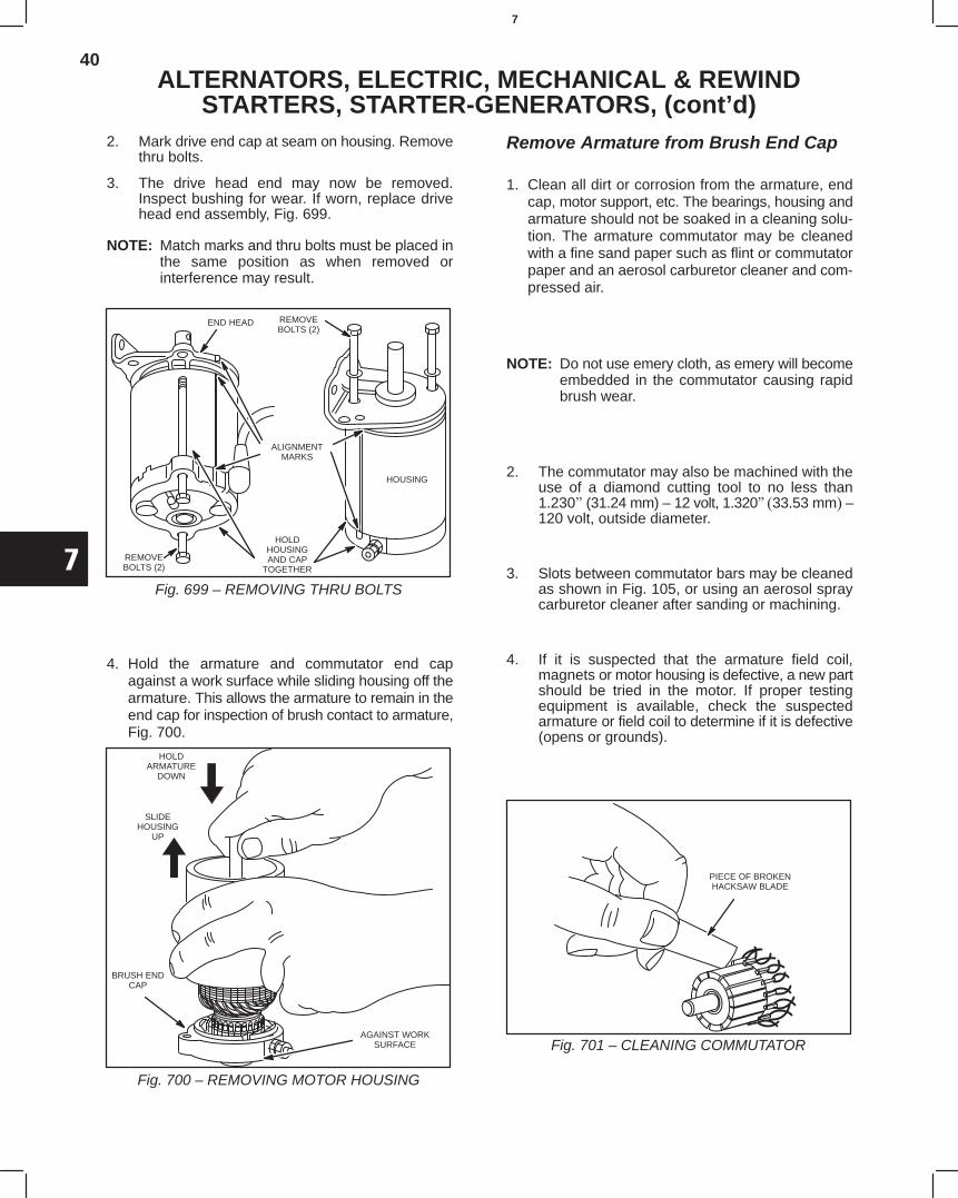
40
7
ALTERNATORS, ELECTRIC, MECHANICAL & REWINDSTARTERS, STARTER-GENERATORS, (cont’d)
2. Mark drive end cap at seam on housing. Removethru bolts.
3. The drive head end may now be removed.Inspect bushing for wear. If worn, replace drivehead end assembly, Fig. 699.
NOTE: Match marks and thru bolts must be placed inthe same position as when removed orinterference may result.
END HEAD
ALIGNMENTMARKS
HOLDHOUSINGAND CAP
TOGETHER
REMOVEBOLTS (2)
REMOVEBOLTS (2)
HOUSING
Fig. 699 – REMOVING THRU BOLTS
4. Hold the armature and commutator end capagainst a work surface while sliding housing off thearmature. This allows the armature to remain in theend cap for inspection of brush contact to armature,Fig. 700.
HOLDARMATURE
DOWN
SLIDEHOUSING
UP
BRUSH ENDCAP
AGAINST WORKSURFACE
Fig. 700 – REMOVING MOTOR HOUSING
Remove Armature from Brush End Cap
1. Clean all dirt or corrosion from the armature, endcap, motor support, etc. The bearings, housing andarmature should not be soaked in a cleaning solu-tion. The armature commutator may be cleanedwith a fine sand paper such as flint or commutatorpaper and an aerosol carburetor cleaner and com-pressed air.
NOTE: Do not use emery cloth, as emery will becomeembedded in the commutator causing rapidbrush wear.
2. The commutator may also be machined with theuse of a diamond cutting tool to no less than1.230 (31.24 mm) – 12 volt, 1.320 33.53 mm –120 volt, outside diameter.
3. Slots between commutator bars may be cleanedas shown in Fig. 105, or using an aerosol spraycarburetor cleaner after sanding or machining.
4. If it is suspected that the armature field coil,magnets or motor housing is defective, a new partshould be tried in the motor. If proper testingequipment is available, check the suspectedarmature or field coil to determine if it is defective(opens or grounds).
PIECE OF BROKENHACKSAW BLADE
Fig. 701 – CLEANING COMMUTATOR
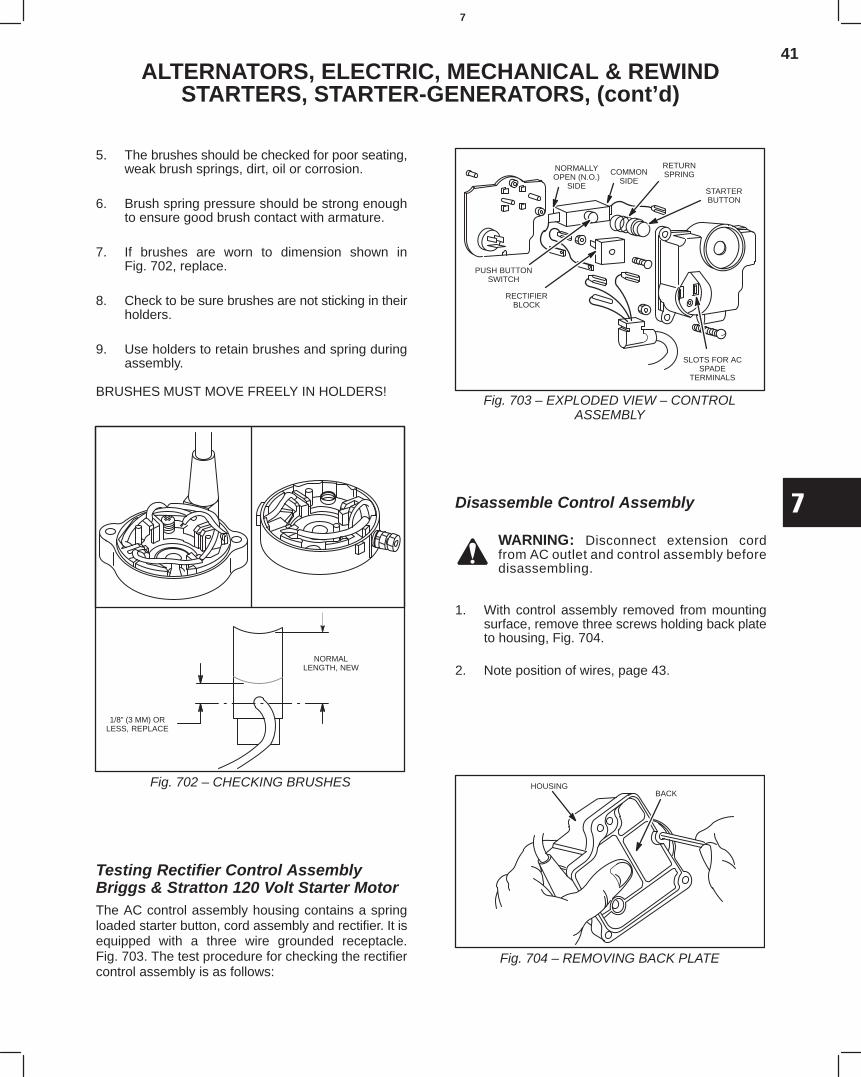
41
7
ALTERNATORS, ELECTRIC, MECHANICAL & REWINDSTARTERS, STARTER-GENERATORS, (cont’d)
5. The brushes should be checked for poor seating,weak brush springs, dirt, oil or corrosion.
6. Brush spring pressure should be strong enoughto ensure good brush contact with armature.
7. If brushes are worn to dimension shown inFig. 702, replace.
8. Check to be sure brushes are not sticking in theirholders.
9. Use holders to retain brushes and spring duringassembly.
BRUSHES MUST MOVE FREELY IN HOLDERS!
NORMALLENGTH, NEW
1/8” (3 MM) ORLESS, REPLACE
Fig. 702 – CHECKING BRUSHES
Testing Rectifier Control AssemblyBriggs & Stratton 120 Volt Starter MotorThe AC control assembly housing contains a springloaded starter button, cord assembly and rectifier. It isequipped with a three wire grounded receptacle.Fig. 703. The test procedure for checking the rectifiercontrol assembly is as follows:
NORMALLYOPEN (N.O.)
SIDE
COMMONSIDE
RETURNSPRING
STARTERBUTTON
SLOTS FOR ACSPADE
TERMINALS
PUSH BUTTONSWITCH
RECTIFIERBLOCK
Fig. 703 – EXPLODED VIEW – CONTROLASSEMBLY
Disassemble Control Assembly
WARNING: Disconnect extension cordfrom AC outlet and control assembly beforedisassembling.
1. With control assembly removed from mountingsurface, remove three screws holding back plateto housing, Fig. 704.
2. Note position of wires, page 43.
BACKHOUSING
Fig. 704 – REMOVING BACK PLATE
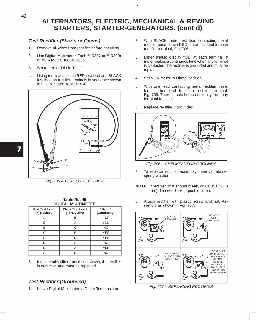
42
7
ALTERNATORS, ELECTRIC, MECHANICAL & REWINDSTARTERS, STARTER-GENERATORS, (cont’d)
Test Rectifier (Shorts or Opens)1. Remove all wires from rectifier before checking.
2. Use Digital Multimeter, Tool (#19357 or #19390)or VOA Meter, Tool #19236.
3. Set meter to “Diode Test.”
4. Using test leads, place RED test lead and BLACKtest lead on rectifier terminals in sequence shownin Fig. 705, and Table No. 49.
“A”
“B”
“D”
“C”
Fig. 705 – TESTING RECTIFIER
Table No. 49DIGITAL MULTIMETER
Red Test Lead(+) Positive
Black Test Lead(–) Negative
“Beep”(Continuity)
A B NO
B A YES
B C NO
C B YES
C D YES
D C NO
D A YES
A D NO
5. If test results differ from those shown, the rectifieris defective and must be replaced.
Test Rectifier (Grounded)1. Leave Digital Multimeter in Diode Test position.
2. With BLACK meter test lead contacting metalrectifier case, touch RED meter test lead to eachrectifier terminal, Fig. 706.
3. Meter should display “OL” at each terminal. Ifmeter makes a continuous tone when any terminalis contacted, the rectifier is grounded and must bereplaced.
4. Set VOA meter to Ohms Position.
5. With one lead contacting metal rectifier case,touch other lead to each rectifier terminal,Fig. 706. There should be no continuity from anyterminal to case.
6. Replace rectifier if grounded.
Fig. 706 – CHECKING FOR GROUNDS
7. To replace rectifier assembly, remove retainerspring washer.
NOTE: If rectifier post should break, drill a 3/16(5.0mm) diameter hole in post location.
8. Attach rectifier with plastic screw and nut. As-semble as shown in Fig. 707.
REMOVERETAINER
REMOVEPOST IFBROKEN
DRILL HOLE3/16” (5.0 MM) DIA. IF REQ.
LOCATE NUTON INSIDE OFSWITCH BOX
ATTACHRECTIFIER
BLOCK WITHNYLON NUTAND SCREW
OR RETAINER
Fig. 707 – REPLACING RECTIFIER
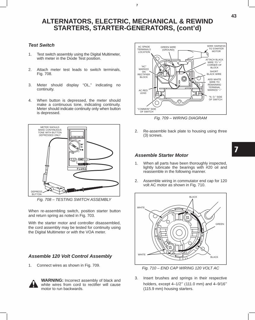
43
7
ALTERNATORS, ELECTRIC, MECHANICAL & REWINDSTARTERS, STARTER-GENERATORS, (cont’d)
Test Switch
1. Test switch assembly using the Digital Multimeter,with meter in the Diode Test position.
2. Attach meter test leads to switch terminals,Fig. 708.
3. Meter should display “OL,” indicating nocontinuity.
4. When button is depressed, the meter shouldmake a continuous tone, indicating continuity.Meter should indicate continuity only when buttonis depressed.
DEPRESSBUTTON
METER SHOULDMAKE CONTINUOUSTONE WITH BUTTONDEPRESSED ONLY
Fig. 708 – TESTING SWITCH ASSEMBLY
When re-assembling switch, position starter buttonand return spring as noted in Fig. 703.
With the starter motor and controller disassembled,the cord assembly may be tested for continuity usingthe Digital Multimeter or with the VOA meter.
Assemble 120 Volt Control Assembly
1. Connect wires as shown in Fig. 709.
WARNING: Incorrect assembly of black andwhite wires from cord to rectifier will causemotor to run backwards.
GREEN WIRE(GROUND)
AC SPADETERMINALSLOCATION
“AC”MARKED
ONRECTIFIER
BLOCK
AC REDLEAD
WIRE HARNESSTO STARTER
MOTOR
ATTACH BLACKWIRE TO “+”CORNER OF
BLOCK
SHORTBLACK WIRE
ADD WHITEWIRE TO
REMAININGTERMINAL
MARKED “–”
“N. O.” SIDEOF SWITCH
“COMMON” SIDEOF SWITCH
Fig. 709 – WIRING DIAGRAM
2. Re-assemble back plate to housing using three(3) screws.
Assemble Starter Motor
1. When all parts have been thoroughly inspected,lightly lubricate the bearings with #20 oil andreassemble in the following manner.
2. Assemble wiring in commutator end cap for 120volt AC motor as shown in Fig. 710.
BLACK
GREEN
BLACK
WHITE
WHITE
Fig. 710 – END CAP WIRING 120 VOLT AC
3. Insert brushes and springs in their respective
holders, except 4–1/2 111.0 mm) and 4–9/16(115.9 mm) housing starters.
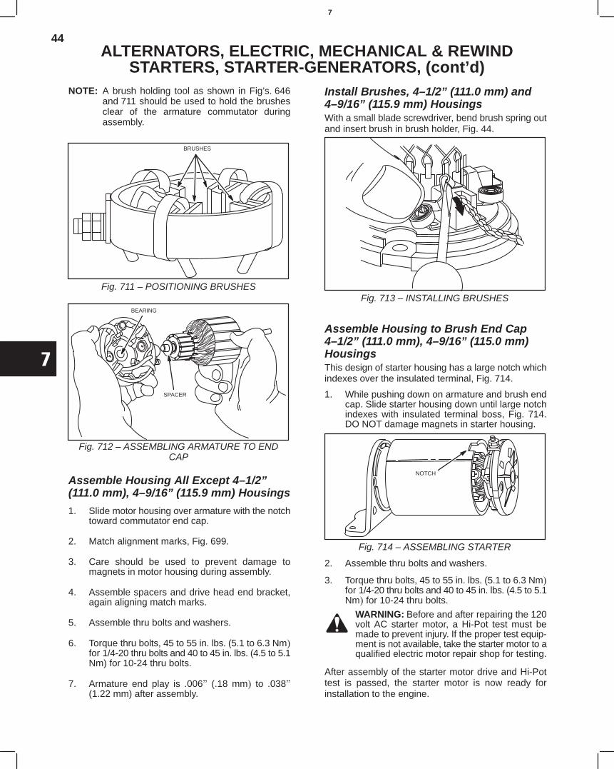
44
7
ALTERNATORS, ELECTRIC, MECHANICAL & REWINDSTARTERS, STARTER-GENERATORS, (cont’d)
NOTE: A brush holding tool as shown in Fig’s. 646and 711 should be used to hold the brushesclear of the armature commutator duringassembly.
BRUSHES
Fig. 711 – POSITIONING BRUSHES
BEARING
SPACER
Fig. 712 – ASSEMBLING ARMATURE TO ENDCAP
Assemble Housing All Except 4–1/2”(111.0 mm), 4–9/16” (115.9 mm) Housings
1. Slide motor housing over armature with the notchtoward commutator end cap.
2. Match alignment marks, Fig. 699.
3. Care should be used to prevent damage tomagnets in motor housing during assembly.
4. Assemble spacers and drive head end bracket,again aligning match marks.
5. Assemble thru bolts and washers.
6. Torque thru bolts, 45 to 55 in. lbs (5.1 to 6.3 Nmfor 1/4-20 thru bolts and 40 to 45 in. lbs. (4.5 to 5.1Nm) for 10-24 thru bolts.
7. Armature end play is .006 (.18 mm to .038(1.22 mm) after assembly.
Install Brushes, 4–1/2” (111.0 mm) and4–9/16” (115.9 mm) HousingsWith a small blade screwdriver, bend brush spring outand insert brush in brush holder, Fig. 44.
Fig. 713 – INSTALLING BRUSHES
Assemble Housing to Brush End Cap4–1/2” (111.0 mm), 4–9/16” (115.0 mm)HousingsThis design of starter housing has a large notch whichindexes over the insulated terminal, Fig. 714.
1. While pushing down on armature and brush endcap. Slide starter housing down until large notchindexes with insulated terminal boss, Fig. 714.DO NOT damage magnets in starter housing.
Fig. 714 – ASSEMBLING STARTER
NOTCH
2. Assemble thru bolts and washers.
3. Torque thru bolts, 45 to 55 in. lbs (5.1 to 6.3 Nmfor 1/4-20 thru bolts and 40 to 45 in. lbs (4.5 to 5.1Nm for 10-24 thru bolts.
WARNING: Before and after repairing the 120volt AC starter motor, a Hi-Pot test must bemade to prevent injury. If the proper test equip-ment is not available, take the starter motor to aqualified electric motor repair shop for testing.
After assembly of the starter motor drive and Hi-Pottest is passed, the starter motor is now ready forinstallation to the engine.
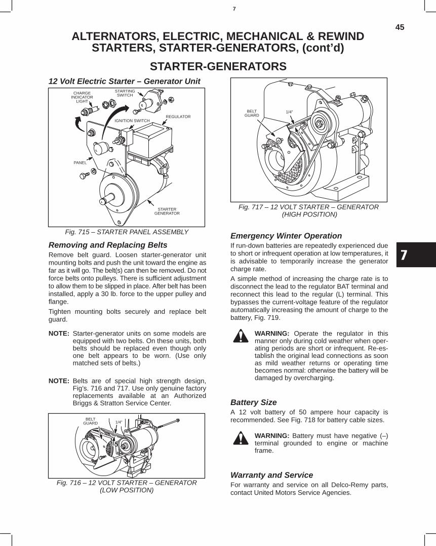
45
7
ALTERNATORS, ELECTRIC, MECHANICAL & REWINDSTARTERS, STARTER-GENERATORS, (cont’d)
STARTER-GENERATORS12 Volt Electric Starter – Generator Unit
Fig. 715 – STARTER PANEL ASSEMBLY
CHARGEINDICATOR
LIGHT
STARTINGSWITCH
IGNITION SWITCHREGULATOR
STARTERGENERATOR
PANEL
Removing and Replacing BeltsRemove belt guard. Loosen starter-generator unitmounting bolts and push the unit toward the engine asfar as it will go. The belt(s) can then be removed. Do notforce belts onto pulleys. There is sufficient adjustmentto allow them to be slipped in place. After belt has beeninstalled, apply a 30 lb. force to the upper pulley andflange.
Tighten mounting bolts securely and replace beltguard.
NOTE: Starter-generator units on some models areequipped with two belts. On these units, bothbelts should be replaced even though onlyone belt appears to be worn. (Use onlymatched sets of belts.)
NOTE: Belts are of special high strength design,Fig’s. 716 and 717. Use only genuine factoryreplacements available at an AuthorizedBriggs & Stratton Service Center.
Fig. 716 – 12 VOLT STARTER – GENERATOR(LOW POSITION)
1/4”BELT
GUARD
Fig. 717 – 12 VOLT STARTER – GENERATOR (HIGH POSITION)
BELTGUARD
1/4”
Emergency Winter OperationIf run-down batteries are repeatedly experienced dueto short or infrequent operation at low temperatures, itis advisable to temporarily increase the generatorcharge rate.A simple method of increasing the charge rate is todisconnect the lead to the regulator BAT terminal andreconnect this lead to the regular (L) terminal. Thisbypasses the current-voltage feature of the regulatorautomatically increasing the amount of charge to thebattery, Fig. 719.
WARNING: Operate the regulator in thismanner only during cold weather when oper-ating periods are short or infrequent. Re-es-tablish the original lead connections as soonas mild weather returns or operating timebecomes normal: otherwise the battery will bedamaged by overcharging.
Battery SizeA 12 volt battery of 50 ampere hour capacity isrecommended. See Fig. 718 for battery cable sizes.
WARNING: Battery must have negative (–)terminal grounded to engine or machineframe.
Warranty and ServiceFor warranty and service on all Delco-Remy parts,contact United Motors Service Agencies.
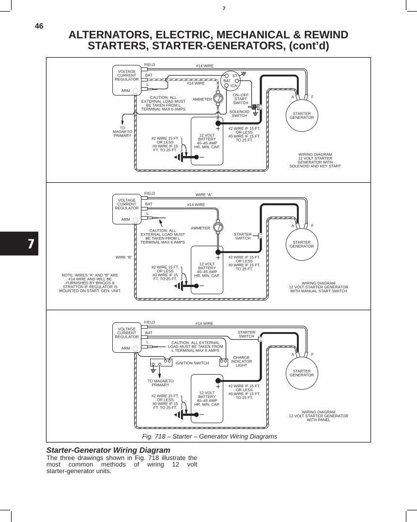
46
7
ALTERNATORS, ELECTRIC, MECHANICAL & REWINDSTARTERS, STARTER-GENERATORS, (cont’d)
Fig. 718 – Starter – Generator Wiring Diagrams
ÍÍÍÍÍÍ
ÍÍÍÍÍÍÍÍÍÍÍÍÍÍÍÍÍÍ
ÍÍÍÍÍÍÍÍÍÍÍÍÍÍÍÍÍÍÍÍÍÍÍÍÍÍÍÍÍÍÍÍÍÍÍÍÍÍÍÍÍÍÍÍÍÍÍÍÍÍÍÍÍÍÍÍÍÍÍÍÍÍÍÍÍÍÍÍÍÍÍÍÍÍÍÍÍÍÍÍÍÍÍÍÍÍÍÍÍÍÍÍÍÍÍÍÍÍÍÍÍÍÍÍÍÍÍÍÍÍÍÍÍÍÍÍÍÍÍÍÍÍÍÍÍÍÍÍÍÍÍÍÍÍÍÍÍÍÍÍÍÍÍÍÍÍÍÍÍÍÍÍÍÍÍÍÍÍÍÍÍÍÍÍÍÍÍÍÍÍÍÍÍÍÍÍÍÍÍÍ
FIELD
BAT
L
CAUTION: ALLEXTERNAL LOAD MUST
BE TAKEN FROM LTERMINAL MAX 6 AMPS
TOMAGNETOPRIMARY
#2 WIRE 15 FT.OR LESS
#0 WIRE IF 15FT. TO 25 FT.
#14 WIRE
#14 WIRE
12 VOLTBATTERY
40–45 AMPHR. MIN. CAP.
#2 WIRE IF 15 FT.OR LESS
#0 WIRE IF 15 FT.TO 25 FT.
STARTERGENERATOR
A F
ST.
ON–OFFSTART
SWITCH
BAT
SOLENOIDSWITCH
IGN
WIRING DIAGRAM12 VOLT STARTERGENERATOR WITH
SOLENOID AND KEY START
VOLTAGECURRENT
REGULATOR
ARM
AMMETER
#2 WIRE 15 FT.OR LESS
#0 WIRE IF 15FT. TO 25 FT.
ÍÍÍÍÍÍÍÍÍÍÍÍÍÍÍÍÍÍÍÍÍÍÍÍÍÍÍÍÍÍÍÍÍÍÍÍÍÍÍÍÍÍÍÍÍÍÍÍÍÍÍÍÍÍÍÍÍÍÍÍÍÍÍÍÍÍÍÍÍÍÍÍÍÍÍÍÍÍÍÍÍÍÍÍÍÍÍÍÍÍÍÍÍÍÍÍÍÍÍÍÍÍÍÍÍÍÍÍÍÍÍÍÍÍÍÍÍÍÍÍÍÍÍÍÍÍÍÍÍÍÍÍÍÍÍÍÍÍÍÍÍÍÍÍÍÍÍÍÍÍÍÍÍÍÍÍÍÍÍÍÍÍÍÍÍÍÍÍÍÍÍÍÍÍÍÍÍÍÍÍ
FIELD
BAT
L
CAUTION: ALLEXTERNAL LOAD MUST
BE TAKEN FROM LTERMINAL MAX 6 AMPS
#14 WIRE
WIRE “A”
12 VOLTBATTERY
40–45 AMPHR. MIN. CAP.
#2 WIRE IF 15 FT.OR LESS
#0 WIRE IF 15 FT.TO 25 FT.
STARTERGENERATOR
A F
STARTERSWITCH
WIRING DIAGRAM12 VOLT STARTER GENERATORWITH MANUAL START SWITCH
VOLTAGECURRENT
REGULATOR
ARM
WIRE “B”
NOTE: WIRES “A” AND “B” ARE#14 WIRE AND WILL BE
FURNISHED BY BRIGGS &STRATTON IF REGULATOR IS
MOUNTED ON START. GEN. UNIT.
AMMETER
#2 WIRE 15 FT.OR LESS
#0 WIRE IF 15FT. TO 25 FT.
ÍÍÍÍÍÍÍÍÍÍÍÍÍÍÍÍÍÍÍÍÍÍÍÍÍÍÍÍÍÍÍÍÍÍÍÍÍÍÍÍÍÍÍÍÍÍÍÍÍÍÍÍÍÍÍÍÍÍÍÍÍÍÍÍÍÍÍÍÍÍÍÍÍÍÍÍÍÍÍÍÍÍÍÍÍÍÍÍÍÍÍÍÍÍÍÍÍÍÍÍÍÍÍÍÍÍÍÍÍÍÍÍÍÍÍÍÍÍÍÍÍÍÍÍÍÍÍÍÍÍÍÍÍÍÍÍÍÍÍÍÍÍÍÍÍÍÍÍÍÍÍÍÍÍÍÍÍÍÍÍÍÍÍÍÍÍÍÍÍÍÍÍÍÍÍÍÍÍÍÍ
FIELD
BAT
L CAUTION: ALL EXTERNALLOAD MUST BE TAKEN FROM
L TERMINAL MAX 6 AMPS
12 VOLTBATTERY
40–45 AMPHR. MIN. CAP.
#2 WIRE IF 15 FT.OR LESS
#0 WIRE IF 15 FT.TO 25 FT.
STARTERGENERATOR
A F
STARTERSWITCH
WIRING DIAGRAM12 VOLT STARTER GENERATOR
WITH PANEL
VOLTAGECURRENT
REGULATOR
ARM
IGNITION SWITCHCHARGE
INDICATORLIGHT
#14 WIRE
TO MAGNETOPRIMARY
Starter-Generator Wiring DiagramThe three drawings shown in Fig. 718 illustrate themost common methods of wiring 12 voltstarter-generator units.
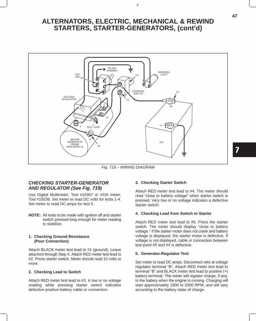
47
7
ALTERNATORS, ELECTRIC, MECHANICAL & REWINDSTARTERS, STARTER-GENERATORS, (cont’d)
Fig. 719 – WIRING DIAGRAM
IGN.SW.
VOLTAGEREGULATOR
F
MOTORGENERATOR
FRAMEGROUNDED #1
A
#5
LACC. LOAD
B
F
#4
STARTINGSWITCH
#2
TO IGN.PRIMARY
#3WARNING
LIGHT
12V
CHECKING STARTER-GENERATORAND REGULATOR (See Fig. 719)Use Digital Multimeter, Tool #19357 or VOA meter,Tool #19236. Set meter to read DC volts for tests 1-4.Set meter to read DC amps for test 5.
NOTE: All tests to be made with ignition off and starterswitch pressed long enough for meter readingto stabilize.
1. Checking Ground Resistance(Poor Connection)
Attach BLACK meter test lead to #1 (ground). Leaveattached through Step 4. Attach RED meter test lead to#2. Press starter switch. Meter should read 10 volts ormore.
2. Checking Lead to Switch
Attach RED meter test lead to #3. A low or no voltagereading while pressing starter switch indicatesdefective positive battery cable or connection.
3. Checking Starter Switch
Attach RED meter test lead to #4. The meter shouldread “close to battery voltage” when starter switch ispressed. Very low or no voltage indicates a defectivestarter switch.
4. Checking Lead from Switch to Starter
Attach RED meter test lead to #5. Press the starterswitch. The meter should display “close to batteryvoltage.” If the starter motor does not crank and batteryvoltage is displayed, the starter motor is defective. Ifvoltage is not displayed, cable or connection betweentest-point #5 and #4 is defective.
5. Generator-Regulator Test
Set meter to read DC amps. Disconnect wire at voltageregulator terminal “B”. Attach RED meter test lead toterminal “B” and BLACK meter test lead to positive (+)battery terminal. The meter will register charge, if any,to the battery when the engine is running. Charging willstart approximately 1800 to 2000 RPM, and will varyaccording to the battery state of charge.
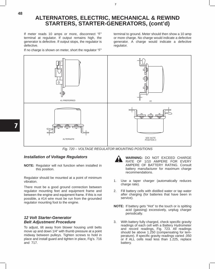
48
7
ALTERNATORS, ELECTRIC, MECHANICAL & REWINDSTARTERS, STARTER-GENERATORS, (cont’d)
If meter reads 10 amps or more, disconnect “F”terminal at regulator. If output remains high, thegenerator is defective. If output stops, the regulator isdefective.If no charge is shown on meter, short the regulator “F”
terminal to ground. Meter should then show a 10 ampor more charge. No charge would indicate a defectivegenerator. A charge would indicate a defectiveregulator.
Fig. 720 – VOLTAGE REGULATOR MOUNTING POSITIONS
#1 PREFERRED #2
ALTERNATESEE NOTEPOSITION 3
Installation of Voltage Regulators
NOTE: Regulator will not function when installed inthis position.
Regulator should be mounted at a point of minimumvibration.
There must be a good ground connection betweenregulator mounting feet and equipment frame andbetween the engine and equipment frame. If this is notpossible, a #14 wire must be run from the groundedregulator mounting foot to the engine.
12 Volt Starter-GeneratorBelt Adjustment ProcedureTo adjust, tilt away from blower housing until beltsmove up and down 1/4” with thumb pressure at a pointmidway between pulleys. Tighten screws to hold inplace and install guard and tighten in place, Fig’s. 716and 717.
WARNING: DO NOT EXCEED CHARGERATE OF 1/10 AMPERE FOR EVERYAMPERE OF BATTERY RATING. Consultbattery manufacturer for maximum chargerecommendations.
1. Use a taper charger (automatically reducescharge rate).
2. Fill battery cells with distilled water or tap waterafter charging (for batteries that have been inservice).
NOTE: If battery gets “Hot” to the touch or is spittingacid (gassing) excessively, unplug chargerperiodically.
3. With battery fully charged, check specific gravityreadings of each cell with a Battery Hydrometerand record readings, Fig. 723. All readingsshould be above 1.250 (compensating for tem-perature). If specific gravity readings varied .050or if ALL cells read less than 1.225, replacebattery.
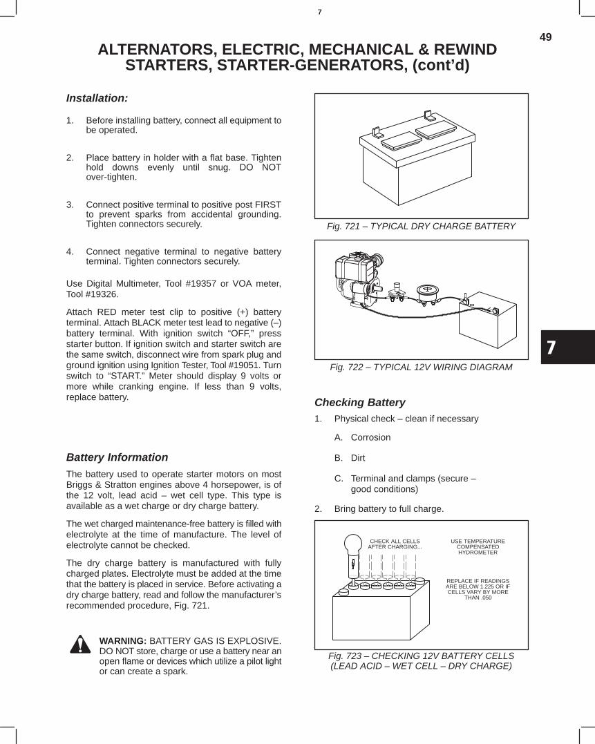
49
7
ALTERNATORS, ELECTRIC, MECHANICAL & REWINDSTARTERS, STARTER-GENERATORS, (cont’d)
Installation:
1. Before installing battery, connect all equipment tobe operated.
2. Place battery in holder with a flat base. Tightenhold downs evenly until snug. DO NOTover-tighten.
3. Connect positive terminal to positive post FIRSTto prevent sparks from accidental grounding.Tighten connectors securely.
4. Connect negative terminal to negative batteryterminal. Tighten connectors securely.
Use Digital Multimeter, Tool #19357 or VOA meter,Tool #19326.
Attach RED meter test clip to positive (+) batteryterminal. Attach BLACK meter test lead to negative (–)battery terminal. With ignition switch “OFF,” pressstarter button. If ignition switch and starter switch arethe same switch, disconnect wire from spark plug andground ignition using Ignition Tester, Tool #19051. Turnswitch to “START.” Meter should display 9 volts ormore while cranking engine. If less than 9 volts,replace battery.
Battery InformationThe battery used to operate starter motors on mostBriggs & Stratton engines above 4 horsepower, is ofthe 12 volt, lead acid – wet cell type. This type isavailable as a wet charge or dry charge battery.
The wet charged maintenance-free battery is filled withelectrolyte at the time of manufacture. The level ofelectrolyte cannot be checked.
The dry charge battery is manufactured with fullycharged plates. Electrolyte must be added at the timethat the battery is placed in service. Before activating adry charge battery, read and follow the manufacturer’srecommended procedure, Fig. 721.
WARNING: BATTERY GAS IS EXPLOSIVE.DO NOT store, charge or use a battery near anopen flame or devices which utilize a pilot lightor can create a spark.
Fig. 721 – TYPICAL DRY CHARGE BATTERY
Fig. 722 – TYPICAL 12V WIRING DIAGRAM
Checking Battery1. Physical check – clean if necessary
A. Corrosion
B. Dirt
C. Terminal and clamps (secure –good conditions)
2. Bring battery to full charge.
Fig. 723 – CHECKING 12V BATTERY CELLS(LEAD ACID – WET CELL – DRY CHARGE)
CHECK ALL CELLSAFTER CHARGING...
USE TEMPERATURECOMPENSATEDHYDROMETER
REPLACE IF READINGSARE BELOW 1.225 OR IFCELLS VARY BY MORE
THAN .050
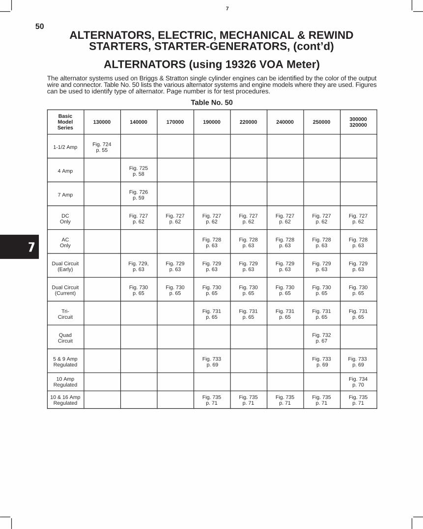
50
7
ALTERNATORS, ELECTRIC, MECHANICAL & REWINDSTARTERS, STARTER-GENERATORS, (cont’d)
ALTERNATORS (using 19326 VOA Meter)The alternator systems used on Briggs & Stratton single cylinder engines can be identified by the color of the outputwire and connector. Table No. 50 lists the various alternator systems and engine models where they are used. Figurescan be used to identify type of alternator. Page number is for test procedures.
Table No. 50
BasicModelSeries
130000 140000 170000 190000 220000 240000 250000 300000320000
1-1/2 Amp Fig. 724p. 55
4 Amp Fig. 725p. 58
7 Amp Fig. 726p. 59
DCOnly
Fig. 727p. 62
Fig. 727p. 62
Fig. 727p. 62
Fig. 727p. 62
Fig. 727p. 62
Fig. 727p. 62
Fig. 727p. 62
ACOnly
Fig. 728p. 63
Fig. 728p. 63
Fig. 728p. 63
Fig. 728p. 63
Fig. 728p. 63
Dual Circuit(Early)
Fig. 729,p. 63
Fig. 729p. 63
Fig. 729p. 63
Fig. 729p. 63
Fig. 729p. 63
Fig. 729p. 63
Fig. 729p. 63
Dual Circuit(Current)
Fig. 730p. 65
Fig. 730p. 65
Fig. 730p. 65
Fig. 730p. 65
Fig. 730p. 65
Fig. 730p. 65
Fig. 730p. 65
Tri-Circuit
Fig. 731p. 65
Fig. 731p. 65
Fig. 731p. 65
Fig. 731p. 65
Fig. 731p. 65
QuadCircuit
Fig. 732p. 67
5 & 9 AmpRegulated
Fig. 733 p. 69
Fig. 733 p. 69
Fig. 733 p. 69
10 AmpRegulated
Fig. 734p. 70
10 & 16 AmpRegulated
Fig. 735p. 71
Fig. 735p. 71
Fig. 735p. 71
Fig. 735p. 71
Fig. 735p. 71
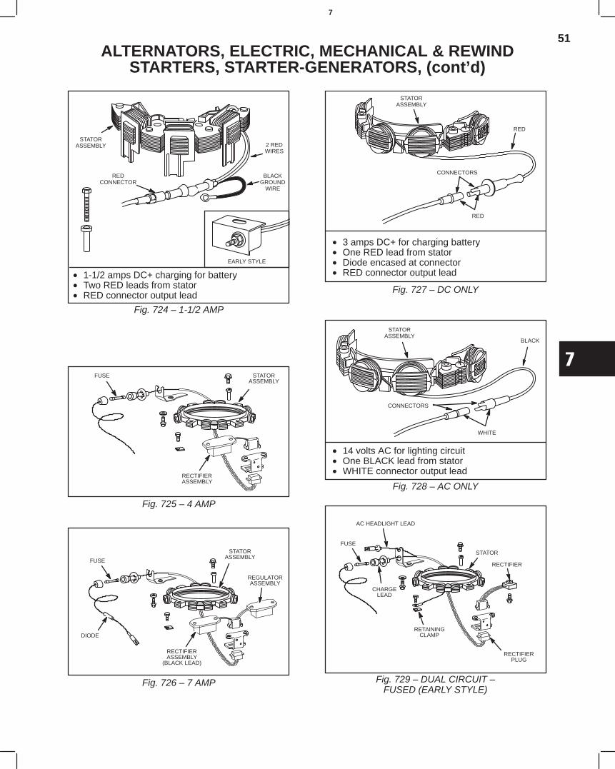
51
7
ALTERNATORS, ELECTRIC, MECHANICAL & REWINDSTARTERS, STARTER-GENERATORS, (cont’d)
Fig. 724 – 1-1/2 AMP
STATORASSEMBLY
REDCONNECTOR
BLACKGROUND
WIRE
EARLY STYLE
2 REDWIRES
• 1-1/2 amps DC+ charging for battery• Two RED leads from stator• RED connector output lead
Fig. 725 – 4 AMP
STATORASSEMBLY
RECTIFIERASSEMBLY
FUSE
Fig. 726 – 7 AMP
FUSE
RECTIFIERASSEMBLY
(BLACK LEAD)
REGULATORASSEMBLY
STATORASSEMBLY
DIODE
STATORASSEMBLY
RED
CONNECTORS
RED
Fig. 727 – DC ONLY
• 3 amps DC+ for charging battery• One RED lead from stator• Diode encased at connector• RED connector output lead
STATORASSEMBLY
BLACK
CONNECTORS
WHITE
Fig. 728 – AC ONLY
• 14 volts AC for lighting circuit• One BLACK lead from stator• WHITE connector output lead
Fig. 729 – DUAL CIRCUIT –FUSED (EARLY STYLE)
AC HEADLIGHT LEAD
STATOR
RECTIFIER
RECTIFIERPLUG
RETAININGCLAMP
CHARGELEAD
FUSE
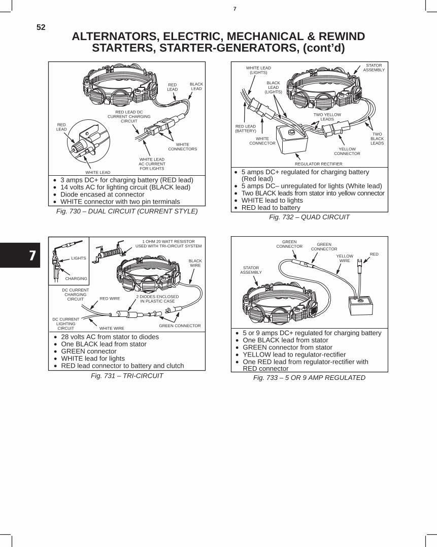
52
7
ALTERNATORS, ELECTRIC, MECHANICAL & REWINDSTARTERS, STARTER-GENERATORS, (cont’d)
REDLEAD
BLACKLEAD
WHITECONNECTORS
WHITE LEADAC CURRENTFOR LIGHTS
RED LEAD DCCURRENT CHARGING
CIRCUITREDLEAD
WHITE LEAD
Fig. 730 – DUAL CIRCUIT (CURRENT STYLE)
• 3 amps DC+ for charging battery (RED lead)• 14 volts AC for lighting circuit (BLACK lead)• Diode encased at connector• WHITE connector with two pin terminals
LIGHTS
CHARGING
1 OHM 20 WATT RESISTORUSED WITH TRI-CIRCUIT SYSTEM
BLACKWIRE
GREEN CONNECTOR
DC CURRENTCHARGING
CIRCUIT2 DIODES ENCLOSED
IN PLASTIC CASE
WHITE WIRE
RED WIRE
DC CURRENTLIGHTINGCIRCUIT
Fig. 731 – TRI-CIRCUIT
• 28 volts AC from stator to diodes• One BLACK lead from stator• GREEN connector• WHITE lead for lights• RED lead connector to battery and clutch
WHITE LEAD(LIGHTS)
RED LEAD(BATTERY)
REGULATOR RECTIFIER
TWO YELLOWLEADS
STATORASSEMBLY
TWOBLACKLEADS
WHITECONNECTOR
BLACKLEAD
(LIGHTS)
YELLOWCONNECTOR
Fig. 732 – QUAD CIRCUIT
• 5 amps DC+ regulated for charging battery(Red lead)
• 5 amps DC– unregulated for lights (White lead)• Two BLACK leads from stator into yellow connector• WHITE lead to lights• RED lead to battery
STATORASSEMBLY
GREENCONNECTOR GREEN
CONNECTOR
YELLOWWIRE
RED
Fig. 733 – 5 OR 9 AMP REGULATED
• 5 or 9 amps DC+ regulated for charging battery• One BLACK lead from stator• GREEN connector from stator• YELLOW lead to regulator-rectifier• One RED lead from regulator-rectifier with
RED connector
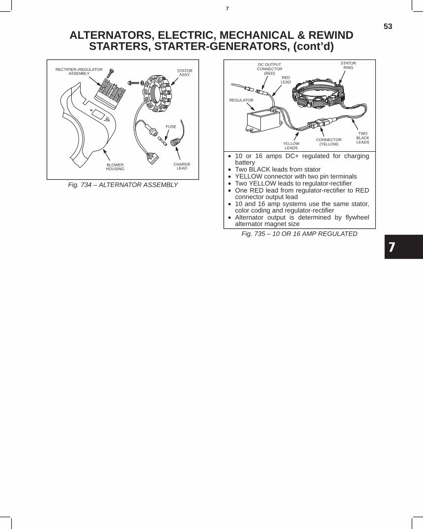
53
7
ALTERNATORS, ELECTRIC, MECHANICAL & REWINDSTARTERS, STARTER-GENERATORS, (cont’d)
Fig. 734 – ALTERNATOR ASSEMBLY
STATORASSY.
RECTIFIER–REGULATORASSEMBLY
BLOWERHOUSING
FUSE
CHARGELEAD
REGULATOR
YELLOWLEADS
TWOBLACKLEADS
REDLEAD
DC OUTPUTCONNECTOR
(RED)
STATORRING
CONNECTOR(YELLOW)
Fig. 735 – 10 OR 16 AMP REGULATED
• 10 or 16 amps DC+ regulated for chargingbattery
• Two BLACK leads from stator• YELLOW connector with two pin terminals• Two YELLOW leads to regulator-rectifier• One RED lead from regulator-rectifier to RED
connector output lead• 10 and 16 amp systems use the same stator,
color coding and regulator-rectifier• Alternator output is determined by flywheel
alternator magnet size
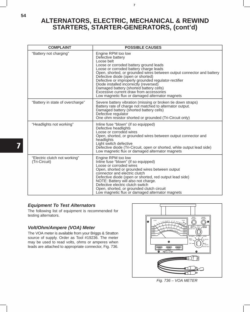
54
7
ALTERNATORS, ELECTRIC, MECHANICAL & REWINDSTARTERS, STARTER-GENERATORS, (cont’d)
COMPLAINT POSSIBLE CAUSES
“Battery not charging” Engine RPM too lowDefective batteryLoose beltLoose or corroded battery ground leadsLoose or corroded battery charge leadsOpen, shorted, or grounded wires between output connector and batteryDefective diode (open or shorted)Defective or improperly grounded regulator-rectifierDiode installed incorrectly (reversed)Damaged battery (shorted battery cells)Excessive current draw from accessoriesLow magnetic flux or damaged alternator magnets
“Battery in state of overcharge” Severe battery vibration (missing or broken tie down straps)Battery rate of charge not matched to alternator output.Damaged battery (shorted battery cells)Defective regulatorOne ohm resistor shorted or grounded (Tri-Circuit only)
“Headlights not working” Inline fuse “blown” (if so equipped)Defective headlightsLoose or corroded wiresOpen, shorted, or grounded wires between output connector andheadlightsLight switch defectiveDefective diode (Tri-Circuit, open or shorted, white output lead side)Low magnetic flux or damaged alternator magnets
“Electric clutch not working” Engine RPM too low(Tri-Circuit) Inline fuse “blown” (if so equipped)
Loose or corroded wiresOpen, shorted or grounded wires between outputconnector and electric clutchDefective diode (open or shorted, red output lead side)NOTE: Battery will also not charge.Defective electric clutch switchOpen, shorted, or grounded clutch circuitLow magnetic flux or damaged alternator magnets
Equipment To Test AlternatorsThe following list of equipment is recommended fortesting alternators.
Volt/Ohm/Ampere (VOA) MeterThe VOA meter is available from your Briggs & Strattonsource of supply. Order as Tool #19236. The metermay be used to read volts, ohms or amperes whenleads are attached to appropriate connector, Fig. 736.
Fig. 736 – VOA METER
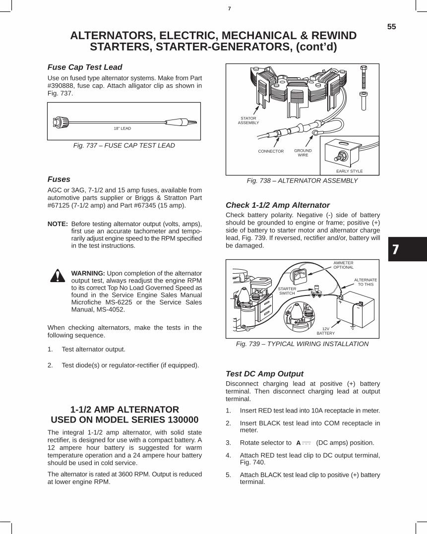
55
7
ALTERNATORS, ELECTRIC, MECHANICAL & REWINDSTARTERS, STARTER-GENERATORS, (cont’d)
Fuse Cap Test LeadUse on fused type alternator systems. Make from Part#390888, fuse cap. Attach alligator clip as shown inFig. 737.
Fig. 737 – FUSE CAP TEST LEAD
18” LEAD
FusesAGC or 3AG, 7-1/2 and 15 amp fuses, available fromautomotive parts supplier or Briggs & Stratton Part#67125 (7-1/2 amp) and Part #67345 (15 amp).
NOTE: Before testing alternator output (volts, amps),first use an accurate tachometer and tempo-rarily adjust engine speed to the RPM specifiedin the test instructions.
WARNING: Upon completion of the alternatoroutput test, always readjust the engine RPMto its correct Top No Load Governed Speed asfound in the Service Engine Sales ManualMicrofiche MS-6225 or the Service SalesManual, MS-4052.
When checking alternators, make the tests in thefollowing sequence.
1. Test alternator output.
2. Test diode(s) or regulator-rectifier (if equipped).
1-1/2 AMP ALTERNATORUSED ON MODEL SERIES 130000
The integral 1-1/2 amp alternator, with solid staterectifier, is designed for use with a compact battery. A12 ampere hour battery is suggested for warmtemperature operation and a 24 ampere hour batteryshould be used in cold service.
The alternator is rated at 3600 RPM. Output is reducedat lower engine RPM.
GROUNDWIRE
STATORASSEMBLY
CONNECTOR
EARLY STYLE
Fig. 738 – ALTERNATOR ASSEMBLY
Check 1-1/2 Amp AlternatorCheck battery polarity. Negative (-) side of batteryshould be grounded to engine or frame; positive (+)side of battery to starter motor and alternator chargelead, Fig. 739. If reversed, rectifier and/or, battery willbe damaged.
ALTERNATETO THIS
STARTERSWITCH
AMMETEROPTIONAL
12VBATTERY
Fig. 739 – TYPICAL WIRING INSTALLATION
Test DC Amp OutputDisconnect charging lead at positive (+) batteryterminal. Then disconnect charging lead at outputterminal.
1. Insert RED test lead into 10A receptacle in meter.
2. Insert BLACK test lead into COM receptacle inmeter.
3. Rotate selector to (DC amps) position.
4. Attach RED test lead clip to DC output terminal,Fig. 740.
5. Attach BLACK test lead clip to positive (+) batteryterminal.
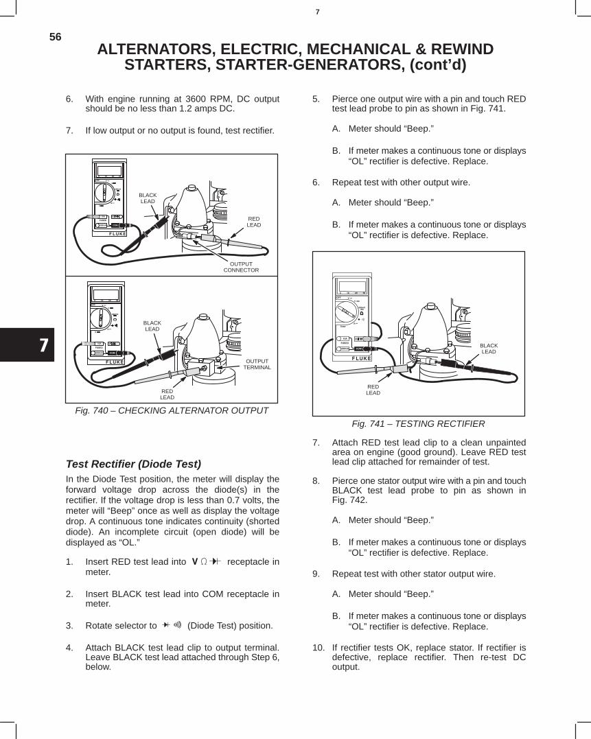
56
7
ALTERNATORS, ELECTRIC, MECHANICAL & REWINDSTARTERS, STARTER-GENERATORS, (cont’d)
6. With engine running at 3600 RPM, DC outputshould be no less than 1.2 amps DC.
7. If low output or no output is found, test rectifier.
BLACKLEAD
REDLEAD
OUTPUTTERMINAL
REDLEAD
OUTPUTCONNECTOR
BLACKLEAD
Fig. 740 – CHECKING ALTERNATOR OUTPUT
Test Rectifier (Diode Test)In the Diode Test position, the meter will display theforward voltage drop across the diode(s) in therectifier. If the voltage drop is less than 0.7 volts, themeter will “Beep” once as well as display the voltagedrop. A continuous tone indicates continuity (shorteddiode). An incomplete circuit (open diode) will bedisplayed as “OL.”
1. Insert RED test lead into receptacle inmeter.
2. Insert BLACK test lead into COM receptacle inmeter.
3. Rotate selector to (Diode Test) position.
4. Attach BLACK test lead clip to output terminal.Leave BLACK test lead attached through Step 6,below.
5. Pierce one output wire with a pin and touch REDtest lead probe to pin as shown in Fig. 741.
A. Meter should “Beep.”
B. If meter makes a continuous tone or displays“OL” rectifier is defective. Replace.
6. Repeat test with other output wire.
A. Meter should “Beep.”
B. If meter makes a continuous tone or displays“OL” rectifier is defective. Replace.
REDLEAD
BLACKLEAD
Fig. 741 – TESTING RECTIFIER
7. Attach RED test lead clip to a clean unpaintedarea on engine (good ground). Leave RED testlead clip attached for remainder of test.
8. Pierce one stator output wire with a pin and touchBLACK test lead probe to pin as shown inFig. 742.
A. Meter should “Beep.”
B. If meter makes a continuous tone or displays“OL” rectifier is defective. Replace.
9. Repeat test with other stator output wire.
A. Meter should “Beep.”
B. If meter makes a continuous tone or displays“OL” rectifier is defective. Replace.
10. If rectifier tests OK, replace stator. If rectifier isdefective, replace rectifier. Then re-test DCoutput.
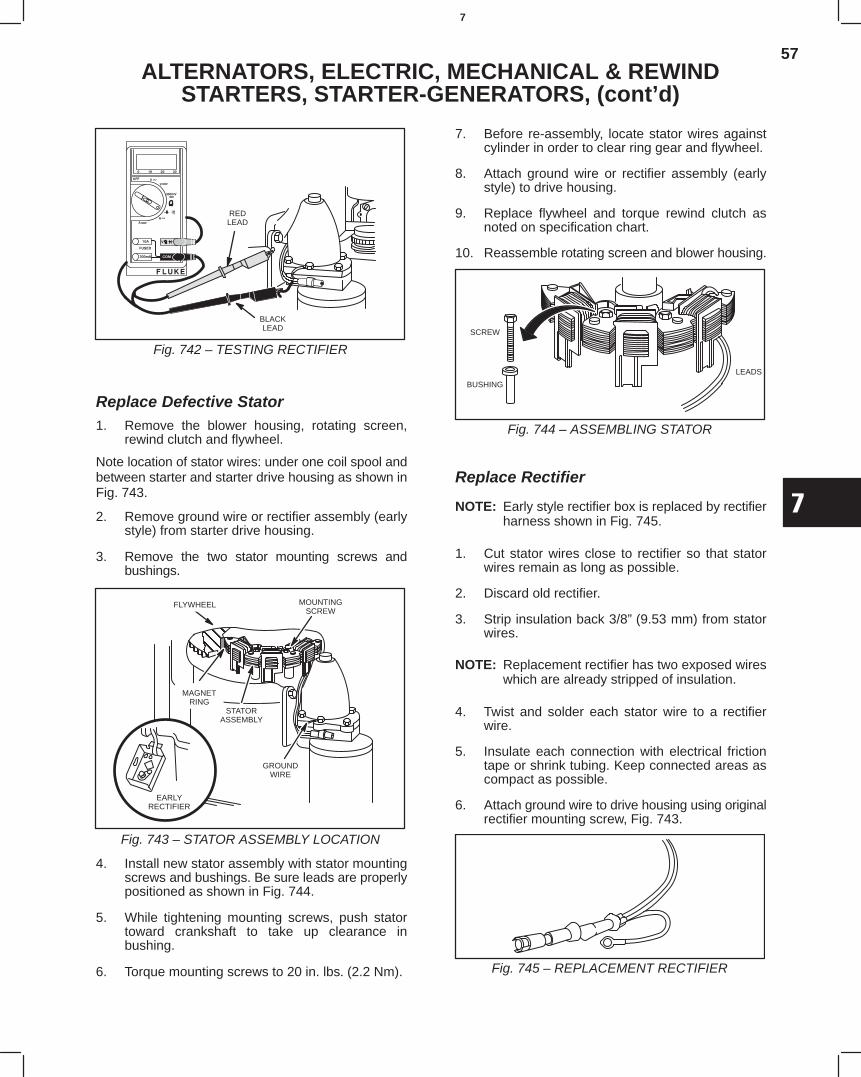
57
7
ALTERNATORS, ELECTRIC, MECHANICAL & REWINDSTARTERS, STARTER-GENERATORS, (cont’d)
REDLEAD
BLACKLEAD
Fig. 742 – TESTING RECTIFIER
Replace Defective Stator1. Remove the blower housing, rotating screen,
rewind clutch and flywheel.
Note location of stator wires: under one coil spool andbetween starter and starter drive housing as shown inFig. 743.
2. Remove ground wire or rectifier assembly (earlystyle) from starter drive housing.
3. Remove the two stator mounting screws andbushings.
GROUNDWIRE
ÇÇÇÇÇÇÇÇÇ
EARLYRECTIFIER
STATORASSEMBLY
MAGNETRING
FLYWHEEL MOUNTINGSCREW
Fig. 743 – STATOR ASSEMBLY LOCATION
4. Install new stator assembly with stator mountingscrews and bushings. Be sure leads are properlypositioned as shown in Fig. 744.
5. While tightening mounting screws, push statortoward crankshaft to take up clearance inbushing.
6. Torque mounting screws to 20 in. lbs (2.2 Nm).
7. Before re-assembly, locate stator wires againstcylinder in order to clear ring gear and flywheel.
8. Attach ground wire or rectifier assembly (earlystyle) to drive housing.
9. Replace flywheel and torque rewind clutch asnoted on specification chart.
10. Reassemble rotating screen and blower housing.
BUSHING
SCREW
LEADS
Fig. 744 – ASSEMBLING STATOR
Replace Rectifier
NOTE: Early style rectifier box is replaced by rectifierharness shown in Fig. 745.
1. Cut stator wires close to rectifier so that statorwires remain as long as possible.
2. Discard old rectifier.
3. Strip insulation back 3/8”(9.53 mm) from statorwires.
NOTE: Replacement rectifier has two exposed wireswhich are already stripped of insulation.
4. Twist and solder each stator wire to a rectifierwire.
5. Insulate each connection with electrical frictiontape or shrink tubing. Keep connected areas ascompact as possible.
6. Attach ground wire to drive housing using originalrectifier mounting screw, Fig. 743.
Fig. 745 – REPLACEMENT RECTIFIER
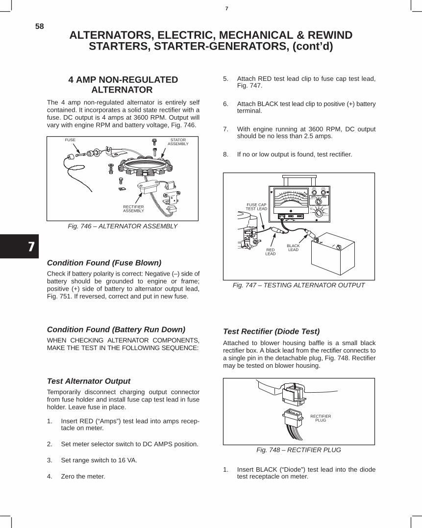
58
7
ALTERNATORS, ELECTRIC, MECHANICAL & REWINDSTARTERS, STARTER-GENERATORS, (cont’d)
4 AMP NON-REGULATEDALTERNATOR
The 4 amp non-regulated alternator is entirely selfcontained. It incorporates a solid state rectifier with afuse. DC output is 4 amps at 3600 RPM. Output willvary with engine RPM and battery voltage, Fig. 746.
Fig. 746 – ALTERNATOR ASSEMBLY
STATORASSEMBLY
RECTIFIERASSEMBLY
FUSE
Condition Found (Fuse Blown)Check if battery polarity is correct: Negative (–) side ofbattery should be grounded to engine or frame;positive (+) side of battery to alternator output lead,Fig. 751. If reversed, correct and put in new fuse.
Condition Found (Battery Run Down)WHEN CHECKING ALTERNATOR COMPONENTS,MAKE THE TEST IN THE FOLLOWING SEQUENCE:
Test Alternator OutputTemporarily disconnect charging output connectorfrom fuse holder and install fuse cap test lead in fuseholder. Leave fuse in place.
1. Insert RED (“Amps”) test lead into amps recep-tacle on meter.
2. Set meter selector switch to DC AMPS position.
3. Set range switch to 16 VA.
4. Zero the meter.
5. Attach RED test lead clip to fuse cap test lead,Fig. 747.
6. Attach BLACK test lead clip to positive (+) batteryterminal.
7. With engine running at 3600 RPM, DC outputshould be no less than 2.5 amps.
8. If no or low output is found, test rectifier.
Fig. 747 – TESTING ALTERNATOR OUTPUT
FUSE CAPTEST LEAD
REDLEAD
BLACKLEAD
Test Rectifier (Diode Test)Attached to blower housing baffle is a small blackrectifier box. A black lead from the rectifier connects toa single pin in the detachable plug, Fig. 748. Rectifiermay be tested on blower housing.
Fig. 748 – RECTIFIER PLUG
RECTIFIERPLUG
1. Insert BLACK (“Diode”) test lead into the diodetest receptacle on meter.
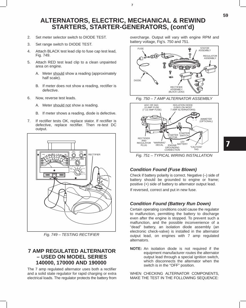
59
7
ALTERNATORS, ELECTRIC, MECHANICAL & REWINDSTARTERS, STARTER-GENERATORS, (cont’d)
2. Set meter selector switch to DIODE TEST.
3. Set range switch to DIODE TEST.
4. Attach BLACK test lead clip to fuse cap test lead,Fig. 749.
5. Attach RED test lead clip to a clean unpaintedarea on engine.
A. Meter should show a reading (approximatelyhalf scale).
B. If meter does not show a reading, rectifier isdefective.
6. Now, reverse test leads.
A. Meter should not show a reading.
B. If meter shows a reading, diode is defective.
7. If rectifier tests OK, replace stator. If rectifier isdefective, replace rectifier. Then re-test DCoutput.
Fig. 749 – TESTING RECTIFIER
RECTIFIER
7 AMP REGULATED ALTERNATOR– USED ON MODEL SERIES140000, 170000 AND 190000
The 7 amp regulated alternator uses both a rectifierand a solid state regulator for rapid charging or extraelectrical loads. The regulator protects the battery from
overcharge. Output will vary with engine RPM andbattery voltage, Fig’s. 750 and 751.
Fig. 750 – 7 AMP ALTERNATOR ASSEMBLY
FUSE
RECTIFIERASSEMBLY
(BLACK LEAD)
REGULATORASSEMBLY
STATORASSEMBLY
DIODE
Fig. 751 – TYPICAL WIRING INSTALLATION
AGC OR 3AG 15 AMP FUSE
(7 1/2 AMP FUSE)
STARTERMOTOR
“WARNING”DECAL
12VBATTERY
“CAUTION”TAG
AMMETER(OPTIONAL)
– +
STARTERSWITCH
ENGINEGROUNDINGCONNECTION
RECTIFIERAND
REGULATORPLUG
ISOLATION DIODE(USED ON MOST
7 AMP ALTERNATORS)
Condition Found (Fuse Blown)Check if battery polarity is correct. Negative (–) side ofbattery should be grounded to engine or frame;positive (+) side of battery to alternator output lead.
If reversed, correct and put in new fuse.
Condition Found (Battery Run Down)Certain operating conditions could cause the regulatorto malfunction, permitting the battery to dischargeeven after the engine is stopped. To prevent such amalfunction, and the possible inconvenience of a“dead” battery, an isolation diode assembly (anelectronic check-valve) is installed in the alternatoroutput lead, on engines with 7 amp regulatedalternators.
NOTE: An isolation diode is not required if theequipment manufacturer routes the alternatoroutput lead through a special ignition switch,which disconnects the alternator when theswitch is in the “OFF” position.
WHEN CHECKING ALTERNATOR COMPONENTS,MAKE THE TEST IN THE FOLLOWING SEQUENCE:
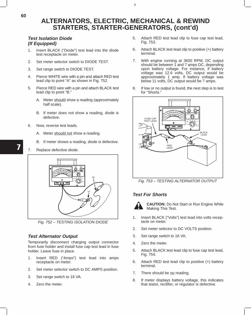
60
7
ALTERNATORS, ELECTRIC, MECHANICAL & REWINDSTARTERS, STARTER-GENERATORS, (cont’d)
Test Isolation Diode(If Equipped)1. Insert BLACK (“Diode”) test lead into the diode
test receptacle on meter.
2. Set meter selector switch to DIODE TEST.
3. Set range switch to DIODE TEST.
4. Pierce WHITE wire with a pin and attach RED testlead clip to point “A” as shown in Fig. 752.
5. Pierce RED wire with a pin and attach BLACK testlead clip to point “B.”
A. Meter should show a reading (approximatelyhalf scale).
B. If meter does not show a reading, diode isdefective.
6. Now, reverse test leads.
A. Meter should not show a reading.
B. If meter shows a reading, diode is defective.
7. Replace defective diode.
Fig. 752 – TESTING ISOLATION DIODE
“A”
“B”
Test Alternator OutputTemporarily disconnect charging output connectorfrom fuse holder and install fuse cap test lead in fuseholder. Leave fuse in place.
1. Insert RED (“Amps”) test lead into ampsreceptacle on meter.
2. Set meter selector switch to DC AMPS position.
3. Set range switch to 16 VA.
4. Zero the meter.
5. Attach RED test lead clip to fuse cap test lead,Fig. 753.
6. Attach BLACK test lead clip to positive (+) batteryterminal.
7. With engine running at 3600 RPM, DC outputshould be between 1 and 7 amps DC, dependingupon battery voltage. For instance, if batteryvoltage was 12.6 volts, DC output would beapproximately 1 amp. If battery voltage wasbelow 11 volts, DC output would be 7 amps.
8. If low or no output is found, the next step is to testfor “Shorts.”
Fig. 753 – TESTING ALTERNATOR OUTPUT
REDLEAD
BLACKLEAD
FUSE CAPTEST LEAD
Test For Shorts
CAUTION: Do Not Start or Run Engine WhileMaking This Test.
1. Insert BLACK (“Volts”) test lead into volts recep-tacle on meter.
2. Set meter selector to DC VOLTS position.
3. Set range switch to 16 VA.
4. Zero the meter.
5. Attach BLACK test lead clip to fuse cap test lead,Fig. 754.
6. Attach RED test lead clip to positive (+) batteryterminal.
7. There should be no reading.
8. If meter displays battery voltage, this indicatesthat stator, rectifier, or regulator is defective.
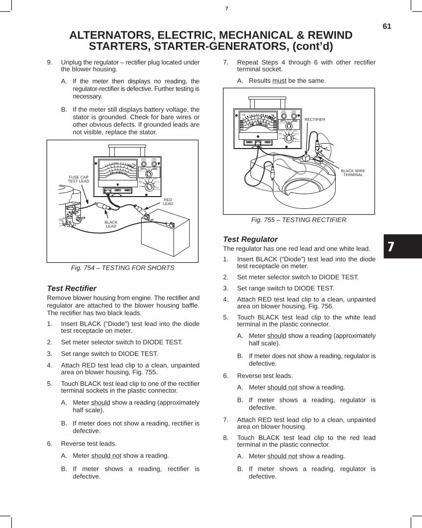
61
7
ALTERNATORS, ELECTRIC, MECHANICAL & REWINDSTARTERS, STARTER-GENERATORS, (cont’d)
9. Unplug the regulator – rectifier plug located underthe blower housing.
A. If the meter then displays no reading, theregulator-rectifier is defective. Further testing isnecessary.
B. If the meter still displays battery voltage, thestator is grounded. Check for bare wires orother obvious defects. If grounded leads arenot visible, replace the stator.
Fig. 754 – TESTING FOR SHORTS
REDLEAD
BLACKLEAD
FUSE CAPTEST LEAD
Test RectifierRemove blower housing from engine. The rectifier andregulator are attached to the blower housing baffle.The rectifier has two black leads.
1. Insert BLACK (“Diode”) test lead into the diodetest receptacle on meter.
2. Set meter selector switch to DIODE TEST.
3. Set range switch to DIODE TEST.
4. Attach RED test lead clip to a clean, unpaintedarea on blower housing, Fig. 755.
5. Touch BLACK test lead clip to one of the rectifierterminal sockets in the plastic connector.
A. Meter should show a reading (approximatelyhalf scale).
B. If meter does not show a reading, rectifier isdefective.
6. Reverse test leads.
A. Meter should not show a reading.
B. If meter shows a reading, rectifier isdefective.
7. Repeat Steps 4 through 6 with other rectifierterminal socket.
A. Results must be the same.
Fig. 755 – TESTING RECTIFIER
BLACK WIRETERMINAL
RECTIFIER
Test RegulatorThe regulator has one red lead and one white lead.
1. Insert BLACK (“Diode”) test lead into the diodetest receptacle on meter.
2. Set meter selector switch to DIODE TEST.
3. Set range switch to DIODE TEST.
4. Attach RED test lead clip to a clean, unpaintedarea on blower housing, Fig. 756.
5. Touch BLACK test lead clip to the white leadterminal in the plastic connector.
A. Meter should show a reading (approximatelyhalf scale).
B. If meter does not show a reading, regulator isdefective.
6. Reverse test leads.
A. Meter should not show a reading.
B. If meter shows a reading, regulator isdefective.
7. Attach RED test lead clip to a clean, unpaintedarea on blower housing.
8. Touch BLACK test lead clip to the red leadterminal in the plastic connector.
A. Meter should not show a reading.
B. If meter shows a reading, regulator isdefective.
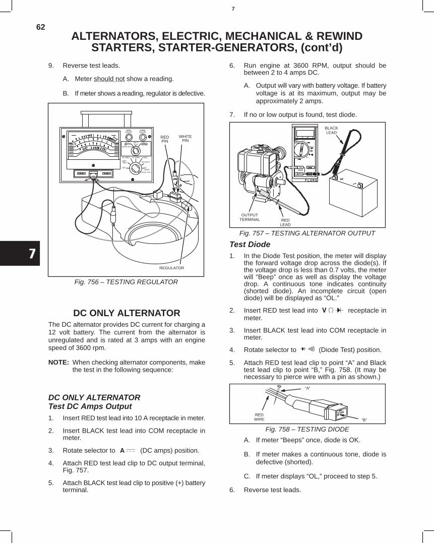
62
7
ALTERNATORS, ELECTRIC, MECHANICAL & REWINDSTARTERS, STARTER-GENERATORS, (cont’d)
9. Reverse test leads.
A. Meter should not show a reading.
B. If meter shows a reading, regulator is defective.
Fig. 756 – TESTING REGULATOR
REDPIN
WHITEPIN
REGULATOR
DC ONLY ALTERNATORThe DC alternator provides DC current for charging a12 volt battery. The current from the alternator isunregulated and is rated at 3 amps with an enginespeed of 3600 rpm.
NOTE: When checking alternator components, makethe test in the following sequence:
DC ONLY ALTERNATORTest DC Amps Output1. Insert RED test lead into 10 A receptacle in meter.
2. Insert BLACK test lead into COM receptacle inmeter.
3. Rotate selector to (DC amps) position.
4. Attach RED test lead clip to DC output terminal,Fig. 757.
5. Attach BLACK test lead clip to positive (+) batteryterminal.
6. Run engine at 3600 RPM, output should bebetween 2 to 4 amps DC.
A. Output will vary with battery voltage. If batteryvoltage is at its maximum, output may beapproximately 2 amps.
7. If no or low output is found, test diode.
REDLEAD
BLACKLEAD
OUTPUTTERMINAL
Fig. 757 – TESTING ALTERNATOR OUTPUT
Test Diode1. In the Diode Test position, the meter will display
the forward voltage drop across the diode(s). Ifthe voltage drop is less than 0.7 volts, the meterwill “Beep” once as well as display the voltagedrop. A continuous tone indicates continuity(shorted diode). An incomplete circuit (opendiode) will be displayed as “OL.”
2. Insert RED test lead into receptacle inmeter.
3. Insert BLACK test lead into COM receptacle inmeter.
4. Rotate selector to (Diode Test) position.
5. Attach RED test lead clip to point “A” and Blacktest lead clip to point “B,” Fig. 758. (It may benecessary to pierce wire with a pin as shown.)
REDWIRE
“A”
“B”
Fig. 758 – TESTING DIODE
A. If meter “Beeps” once, diode is OK.
B. If meter makes a continuous tone, diode isdefective (shorted).
C. If meter displays “OL,” proceed to step 5.
6. Reverse test leads.
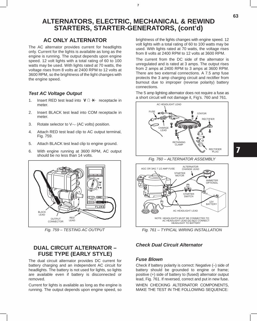
63
7
ALTERNATORS, ELECTRIC, MECHANICAL & REWINDSTARTERS, STARTER-GENERATORS, (cont’d)
AC ONLY ALTERNATORThe AC alternator provides current for headlightsonly. Current for the lights is available as long as theengine is running. The output depends upon enginespeed. 12 volt lights with a total rating of 60 to 100watts may be used. With lights rated at 70 watts, thevoltage rises from 8 volts at 2400 RPM to 12 volts at3600 RPM, so the brightness of the light changes withthe engine speed.
Test AC Voltage Output1. Insert RED test lead into receptacle in
meter.
2. Insert BLACK test lead into COM receptacle inmeter.
3. Rotate selector to V (AC volts) position.
4. Attach RED test lead clip to AC output terminal,Fig. 759.
5. Attach BLACK test lead clip to engine ground.
6. With engine running at 3600 RPM, AC outputshould be no less than 14 volts.
REDLEAD
OUTPUTCONNECTOR
BLACKLEAD
Fig. 759 – TESTING AC OUTPUT
DUAL CIRCUIT ALTERNATOR –FUSE TYPE (EARLY STYLE)
The dual circuit alternator provides DC current forbattery charging and an independent AC circuit forheadlights. The battery is not used for lights, so lightsare available even if battery is disconnected orremoved.
Current for lights is available as long as the engine isrunning. The output depends upon engine speed, so
brightness of the lights changes with engine speed. 12volt lights with a total rating of 60 to 100 watts may beused. With lights rated at 70 watts, the voltage risesfrom 8 volts at 2400 RPM to 12 volts at 3600 RPM.
The current from the DC side of the alternator isunregulated and is rated at 3 amps. The output risesfrom 2 amps at 2400 RPM to 3 amps at 3600 RPM.There are two external connections. A 7.5 amp fuseprotects the 3 amp charging circuit and rectifier fromburnout due to improper (reverse polarity) batteryconnections.
The 5 amp lighting alternator does not require a fuse asa short circuit will not damage it, Fig’s. 760 and 761.
Fig. 760 – ALTERNATOR ASSEMBLY
AC HEADLIGHT LEAD
STATOR
RECTIFIER
RETAININGCLAMP
CHARGELEAD
FUSE
RECTIFIERPLUG
Fig. 761 – TYPICAL WIRING INSTALLATION
AGC OR 3AG 7 1/2 AMP FUSE
HEADLIGHTS MUST BE CONNECTED TOAC HEADLIGHT LEAD DO NOT CONNECT
HEADLIGHT TO BATTERY
NOTE:
STARTERMOTOR
ALTERNATORCHANGE LEAD
STARTERSWITCH
AMMETEROPTIONAL
12VBATTERY
AC HEADLIGHT LEAD
Check Dual Circuit Alternator
Fuse BlownCheck if battery polarity is correct: Negative (–) side ofbattery should be grounded to engine or frame;positive (+) side of battery to (fused) alternator outputlead, Fig. 761. If reversed, correct and put in new fuse.
WHEN CHECKING ALTERNATOR COMPONENTS,MAKE THE TEST IN THE FOLLOWING SEQUENCE:
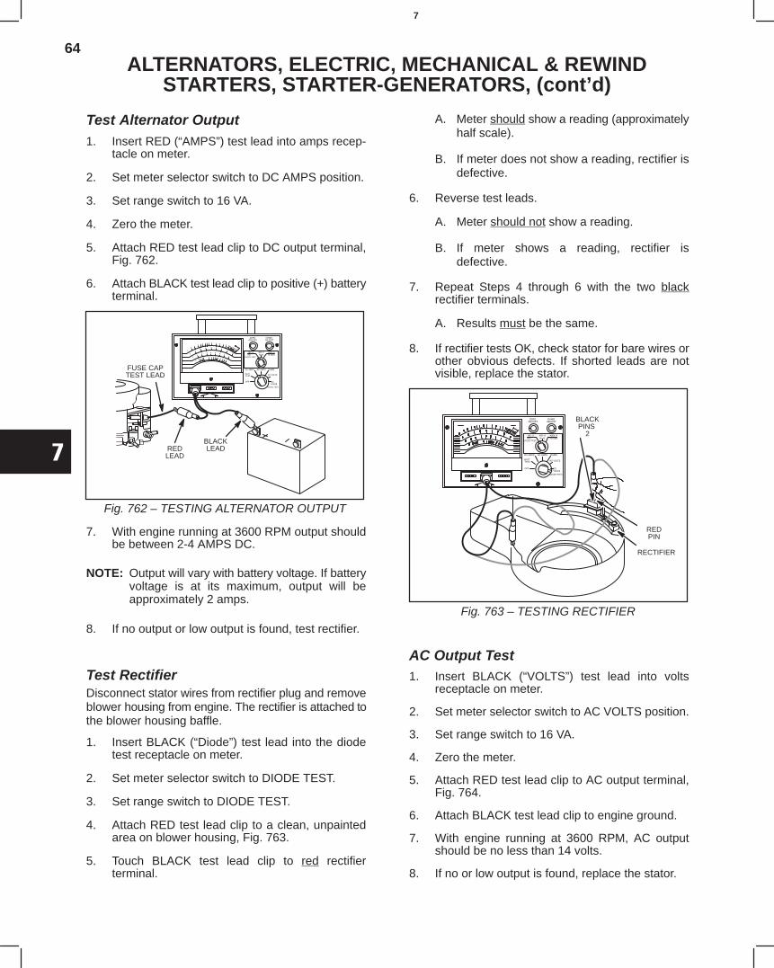
64
7
ALTERNATORS, ELECTRIC, MECHANICAL & REWINDSTARTERS, STARTER-GENERATORS, (cont’d)
Test Alternator Output1. Insert RED (“AMPS”) test lead into amps recep-
tacle on meter.
2. Set meter selector switch to DC AMPS position.
3. Set range switch to 16 VA.
4. Zero the meter.
5. Attach RED test lead clip to DC output terminal,Fig. 762.
6. Attach BLACK test lead clip to positive (+) batteryterminal.
Fig. 762 – TESTING ALTERNATOR OUTPUT
FUSE CAPTEST LEAD
REDLEAD
BLACKLEAD
7. With engine running at 3600 RPM output shouldbe between 2-4 AMPS DC.
NOTE: Output will vary with battery voltage. If batteryvoltage is at its maximum, output will beapproximately 2 amps.
8. If no output or low output is found, test rectifier.
Test RectifierDisconnect stator wires from rectifier plug and removeblower housing from engine. The rectifier is attached tothe blower housing baffle.
1. Insert BLACK (“Diode”) test lead into the diodetest receptacle on meter.
2. Set meter selector switch to DIODE TEST.
3. Set range switch to DIODE TEST.
4. Attach RED test lead clip to a clean, unpaintedarea on blower housing, Fig. 763.
5. Touch BLACK test lead clip to red rectifierterminal.
A. Meter should show a reading (approximatelyhalf scale).
B. If meter does not show a reading, rectifier isdefective.
6. Reverse test leads.
A. Meter should not show a reading.
B. If meter shows a reading, rectifier isdefective.
7. Repeat Steps 4 through 6 with the two blackrectifier terminals.
A. Results must be the same.
8. If rectifier tests OK, check stator for bare wires orother obvious defects. If shorted leads are notvisible, replace the stator.
Fig. 763 – TESTING RECTIFIER
REDPIN
BLACKPINS
2
RECTIFIER
AC Output Test1. Insert BLACK (“VOLTS”) test lead into volts
receptacle on meter.
2. Set meter selector switch to AC VOLTS position.
3. Set range switch to 16 VA.
4. Zero the meter.
5. Attach RED test lead clip to AC output terminal,Fig. 764.
6. Attach BLACK test lead clip to engine ground.
7. With engine running at 3600 RPM, AC outputshould be no less than 14 volts.
8. If no or low output is found, replace the stator.
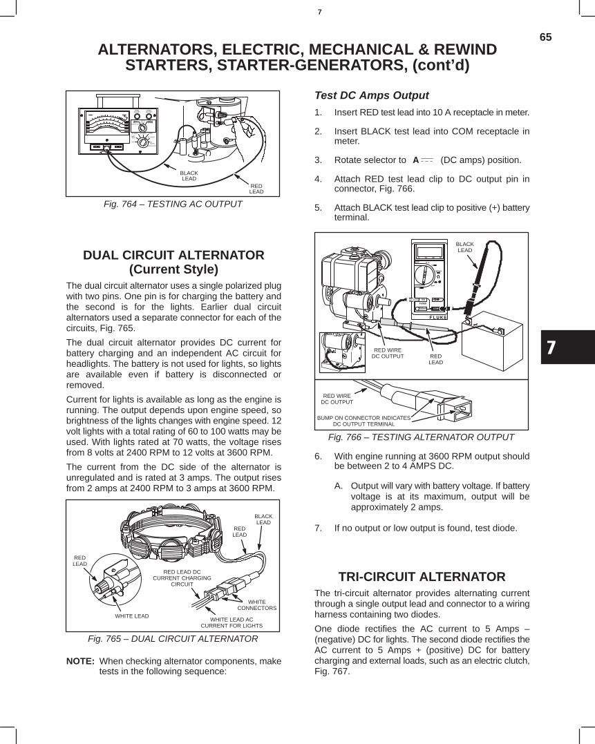
65
7
ALTERNATORS, ELECTRIC, MECHANICAL & REWINDSTARTERS, STARTER-GENERATORS, (cont’d)
Fig. 764 – TESTING AC OUTPUT
BLACKLEAD
REDLEAD
DUAL CIRCUIT ALTERNATOR(Current Style)
The dual circuit alternator uses a single polarized plugwith two pins. One pin is for charging the battery andthe second is for the lights. Earlier dual circuitalternators used a separate connector for each of thecircuits, Fig. 765.
The dual circuit alternator provides DC current forbattery charging and an independent AC circuit forheadlights. The battery is not used for lights, so lightsare available even if battery is disconnected orremoved.
Current for lights is available as long as the engine isrunning. The output depends upon engine speed, sobrightness of the lights changes with engine speed. 12volt lights with a total rating of 60 to 100 watts may beused. With lights rated at 70 watts, the voltage risesfrom 8 volts at 2400 RPM to 12 volts at 3600 RPM.
The current from the DC side of the alternator isunregulated and is rated at 3 amps. The output risesfrom 2 amps at 2400 RPM to 3 amps at 3600 RPM.
WHITE LEAD ACCURRENT FOR LIGHTS
REDLEAD
BLACKLEAD
WHITECONNECTORS
RED LEAD DCCURRENT CHARGING
CIRCUIT
REDLEAD
WHITE LEAD
Fig. 765 – DUAL CIRCUIT ALTERNATOR
NOTE: When checking alternator components, maketests in the following sequence:
Test DC Amps Output1. Insert RED test lead into 10 A receptacle in meter.
2. Insert BLACK test lead into COM receptacle inmeter.
3. Rotate selector to (DC amps) position.
4. Attach RED test lead clip to DC output pin inconnector, Fig. 766.
5. Attach BLACK test lead clip to positive (+) batteryterminal.
RED WIREDC OUTPUT RED
LEAD
BLACKLEAD
RED WIREDC OUTPUT
BUMP ON CONNECTOR INDICATESDC OUTPUT TERMINAL
Fig. 766 – TESTING ALTERNATOR OUTPUT
6. With engine running at 3600 RPM output shouldbe between 2 to 4 AMPS DC.
A. Output will vary with battery voltage. If batteryvoltage is at its maximum, output will beapproximately 2 amps.
7. If no output or low output is found, test diode.
TRI-CIRCUIT ALTERNATORThe tri-circuit alternator provides alternating currentthrough a single output lead and connector to a wiringharness containing two diodes.
One diode rectifies the AC current to 5 Amps –(negative) DC for lights. The second diode rectifies theAC current to 5 Amps + (positive) DC for batterycharging and external loads, such as an electric clutch,Fig. 767.
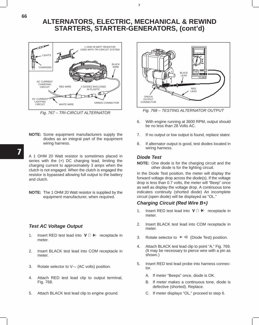
66
7
ALTERNATORS, ELECTRIC, MECHANICAL & REWINDSTARTERS, STARTER-GENERATORS, (cont’d)
LIGHTS
CHARGING
1 OHM 29 WATT RESISTORUSED WITH TRI-CIRCUIT SYSTEM
BLACKWIRE
GREEN CONNECTOR
DC CURRENTCHARGING
CIRCUIT 2 DIODES ENCLOSEDIN PLASTIC
WHITE WIRE
RED WIRE
DC CURRENTLIGHTINGCIRCUIT
Fig. 767 – TRI-CIRCUIT ALTERNATOR
NOTE: Some equipment manufacturers supply thediodes as an integral part of the equipmentwiring harness.
A 1 OHM 20 Watt resistor is sometimes placed inseries with the (+) DC charging lead, limiting thecharging current to approximately 3 amps when theclutch is not engaged. When the clutch is engaged theresistor is bypassed allowing full output to the batteryand clutch.
NOTE: The 1 OHM 20 Watt resistor is supplied by theequipment manufacturer, when required.
Test AC Voltage Output
1. Insert RED test lead into receptacle inmeter.
2. Insert BLACK test lead into COM receptacle inmeter.
3. Rotate selector to V (AC volts) position.
4. Attach RED test lead clip to output terminal,Fig. 768.
5. Attach BLACK test lead clip to engine ground.
BLACKLEAD
REDLEAD
GREENOUTPUT
CONNECTOR
Fig. 768 – TESTING ALTERNATOR OUTPUT
6. With engine running at 3600 RPM, output shouldbe no less than 28 Volts AC.
7. If no output or low output is found, replace stator.
8. If alternator output is good, test diodes located inwiring harness.
Diode TestNOTE: One diode is for the charging circuit and the
other diode is for the lighting circuit.
In the Diode Test position, the meter will display theforward voltage drop across the diode(s). If the voltagedrop is less than 0.7 volts, the meter will “Beep” onceas well as display the voltage drop. A continuous toneindicates continuity (shorted diode) An incompletecircuit (open diode) will be displayed as “OL.”
Charging Circuit (Red Wire B+)
1. Insert RED test lead into receptacle inmeter.
2. Insert BLACK test lead into COM receptacle inmeter.
3. Rotate selector to (Diode Test) position.
4. Attach BLACK test lead clip to point “A,” Fig. 769.(It may be necessary to pierce wire with a pin asshown.)
5. Insert RED test lead probe into harness connec-tor.
A. If meter “Beeps” once, diode is OK.
B. If meter makes a continuous tone, diode isdefective (shorted). Replace.
C. If meter displays “OL,” proceed to step 6.
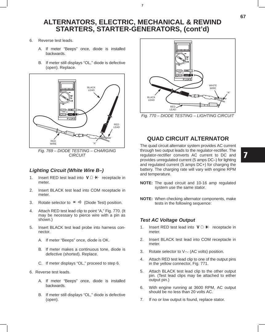
67
7
ALTERNATORS, ELECTRIC, MECHANICAL & REWINDSTARTERS, STARTER-GENERATORS, (cont’d)
6. Reverse test leads.
A. If meter “Beeps” once, diode is installedbackwards.
B. If meter still displays “OL,” diode is defective(open). Replace.
BLACKLEAD
REDLEAD
“A”REDWIRE
Fig. 769 – DIODE TESTING – CHARGINGCIRCUIT
Lighting Circuit (White Wire B–)1. Insert RED test lead into receptacle in
meter.
2. Insert BLACK test lead into COM receptacle inmeter.
3. Rotate selector to (Diode Test) position.
4. Attach RED test lead clip to point “A,” Fig. 770. (Itmay be necessary to pierce wire with a pin asshown.)
5. Insert BLACK test lead probe into harness con-nector.
A. If meter “Beeps” once, diode is OK.
B. If meter makes a continuous tone, diode isdefective (shorted). Replace.
C. If meter displays “OL,” proceed to step 6.
6. Reverse test leads.
A. If meter “Beeps” once, diode is installedbackwards.
B. If meter still displays “OL,” diode is defective(open).
BLACKLEAD
WHITEWIRE
REDLEAD
“A”
Fig. 770 – DIODE TESTING – LIGHTING CIRCUIT
QUAD CIRCUIT ALTERNATORThe quad circuit alternator system provides AC currentthrough two output leads to the regulator-rectifier. Theregulator-rectifier converts AC current to DC andprovides unregulated current (5 amps DC–) for lightingand regulated current (5 amps DC+) for charging thebattery. The charging rate will vary with engine RPMand temperature.
NOTE: The quad circuit and 10-16 amp regulatedsystem use the same stator.
NOTE: When checking alternator components, maketests in the following sequence:
Test AC Voltage Output1. Insert RED test lead into receptacle in
meter.
2. Insert BLACK test lead into COM receptacle inmeter.
3. Rotate selector to V (AC volts) position.
4. Attach RED test lead clip to one of the output pinsin the yellow connector, Fig. 771.
5. Attach BLACK test lead clip to the other outputpin. (Test lead clips may be attached to eitheroutput pin.)
6. With engine running at 3600 RPM, AC outputshould be no less than 20 volts AC.
7. If no or low output is found, replace stator.
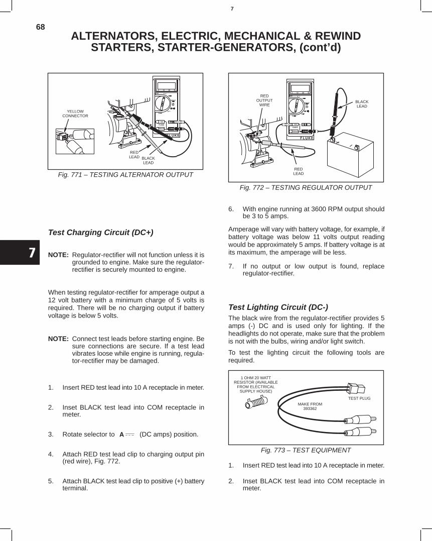
68
7
ALTERNATORS, ELECTRIC, MECHANICAL & REWINDSTARTERS, STARTER-GENERATORS, (cont’d)
YELLOWCONNECTOR
REDLEAD BLACK
LEAD
Fig. 771 – TESTING ALTERNATOR OUTPUT
Test Charging Circuit (DC+)
NOTE: Regulator-rectifier will not function unless it isgrounded to engine. Make sure the regulator-rectifier is securely mounted to engine.
When testing regulator-rectifier for amperage output a12 volt battery with a minimum charge of 5 volts isrequired. There will be no charging output if batteryvoltage is below 5 volts.
NOTE: Connect test leads before starting engine. Besure connections are secure. If a test leadvibrates loose while engine is running, regula-tor-rectifier may be damaged.
1. Insert RED test lead into 10 A receptacle in meter.
2. Inset BLACK test lead into COM receptacle inmeter.
3. Rotate selector to (DC amps) position.
4. Attach RED test lead clip to charging output pin(red wire), Fig. 772.
5. Attach BLACK test lead clip to positive (+) batteryterminal.
REDOUTPUT
WIRE
REDLEAD
BLACKLEAD
Fig. 772 – TESTING REGULATOR OUTPUT
6. With engine running at 3600 RPM output shouldbe 3 to 5 amps.
Amperage will vary with battery voltage, for example, ifbattery voltage was below 11 volts output readingwould be approximately 5 amps. If battery voltage is atits maximum, the amperage will be less.
7. If no output or low output is found, replaceregulator-rectifier.
Test Lighting Circuit (DC-)The black wire from the regulator-rectifier provides 5amps (-) DC and is used only for lighting. If theheadlights do not operate, make sure that the problemis not with the bulbs, wiring and/or light switch.
To test the lighting circuit the following tools arerequired.
1 OHM 20 WATTRESISTOR (AVAILABLE
FROM ELECTRICALSUPPLY HOUSE)
MAKE FROM393362
TEST PLUG
Fig. 773 – TEST EQUIPMENT
1. Insert RED test lead into 10 A receptacle in meter.
2. Inset BLACK test lead into COM receptacle inmeter.
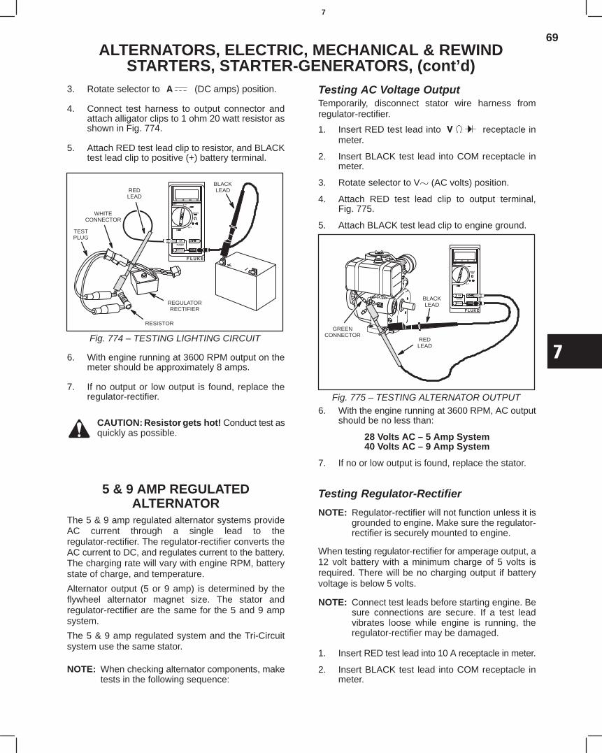
69
7
ALTERNATORS, ELECTRIC, MECHANICAL & REWINDSTARTERS, STARTER-GENERATORS, (cont’d)
3. Rotate selector to (DC amps) position.
4. Connect test harness to output connector andattach alligator clips to 1 ohm 20 watt resistor asshown in Fig. 774.
5. Attach RED test lead clip to resistor, and BLACKtest lead clip to positive (+) battery terminal.
REGULATORRECTIFIER
REDLEAD
WHITECONNECTOR
TESTPLUG
RESISTOR
BLACKLEAD
Fig. 774 – TESTING LIGHTING CIRCUIT
6. With engine running at 3600 RPM output on themeter should be approximately 8 amps.
7. If no output or low output is found, replace theregulator-rectifier.
CAUTION: Resistor gets hot! Conduct test asquickly as possible.
5 & 9 AMP REGULATEDALTERNATOR
The 5 & 9 amp regulated alternator systems provideAC current through a single lead to theregulator-rectifier. The regulator-rectifier converts theAC current to DC, and regulates current to the battery.The charging rate will vary with engine RPM, batterystate of charge, and temperature.
Alternator output (5 or 9 amp) is determined by theflywheel alternator magnet size. The stator andregulator-rectifier are the same for the 5 and 9 ampsystem.
The 5 & 9 amp regulated system and the Tri-Circuitsystem use the same stator.
NOTE: When checking alternator components, maketests in the following sequence:
Testing AC Voltage OutputTemporarily, disconnect stator wire harness fromregulator-rectifier.
1. Insert RED test lead into receptacle inmeter.
2. Insert BLACK test lead into COM receptacle inmeter.
3. Rotate selector to V (AC volts) position.
4. Attach RED test lead clip to output terminal,Fig. 775.
5. Attach BLACK test lead clip to engine ground.
BLACKLEAD
REDLEAD
GREENCONNECTOR
Fig. 775 – TESTING ALTERNATOR OUTPUT6. With the engine running at 3600 RPM, AC output
should be no less than:
28 Volts AC – 5 Amp System40 Volts AC – 9 Amp System
7. If no or low output is found, replace the stator.
Testing Regulator-Rectifier
NOTE: Regulator-rectifier will not function unless it isgrounded to engine. Make sure the regulator-rectifier is securely mounted to engine.
When testing regulator-rectifier for amperage output, a12 volt battery with a minimum charge of 5 volts isrequired. There will be no charging output if batteryvoltage is below 5 volts.
NOTE: Connect test leads before starting engine. Besure connections are secure. If a test leadvibrates loose while engine is running, theregulator-rectifier may be damaged.
1. Insert RED test lead into 10 A receptacle in meter.
2. Insert BLACK test lead into COM receptacle inmeter.
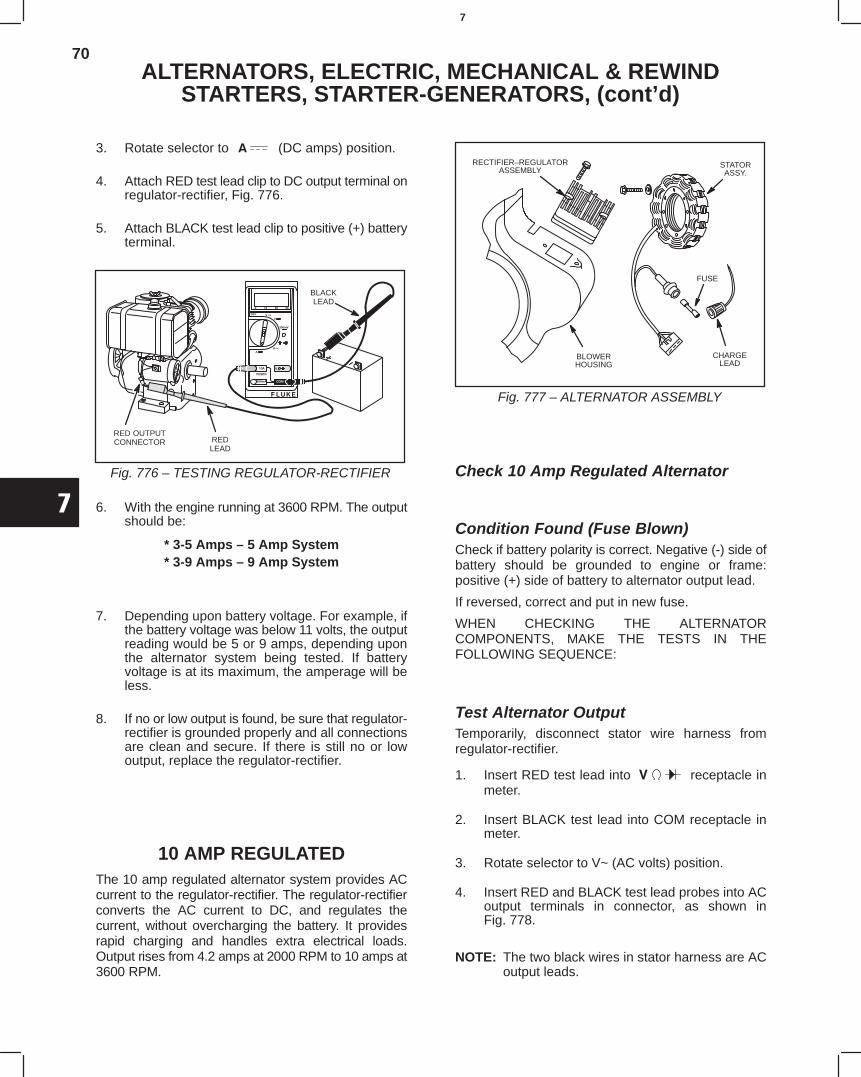
70
7
ALTERNATORS, ELECTRIC, MECHANICAL & REWINDSTARTERS, STARTER-GENERATORS, (cont’d)
3. Rotate selector to (DC amps) position.
4. Attach RED test lead clip to DC output terminal onregulator-rectifier, Fig. 776.
5. Attach BLACK test lead clip to positive (+) batteryterminal.
BLACKLEAD
REDLEAD
RED OUTPUTCONNECTOR
Fig. 776 – TESTING REGULATOR-RECTIFIER
6. With the engine running at 3600 RPM. The outputshould be:
* 3-5 Amps – 5 Amp System* 3-9 Amps – 9 Amp System
7. Depending upon battery voltage. For example, ifthe battery voltage was below 11 volts, the outputreading would be 5 or 9 amps, depending uponthe alternator system being tested. If batteryvoltage is at its maximum, the amperage will beless.
8. If no or low output is found, be sure that regulator-rectifier is grounded properly and all connectionsare clean and secure. If there is still no or lowoutput, replace the regulator-rectifier.
10 AMP REGULATEDThe 10 amp regulated alternator system provides ACcurrent to the regulator-rectifier. The regulator-rectifierconverts the AC current to DC, and regulates thecurrent, without overcharging the battery. It providesrapid charging and handles extra electrical loads.Output rises from 4.2 amps at 2000 RPM to 10 amps at3600 RPM.
Fig. 777 – ALTERNATOR ASSEMBLY
STATORASSY.
RECTIFIER–REGULATORASSEMBLY
BLOWERHOUSING
FUSE
CHARGELEAD
Check 10 Amp Regulated Alternator
Condition Found (Fuse Blown)Check if battery polarity is correct. Negative (-) side ofbattery should be grounded to engine or frame:positive (+) side of battery to alternator output lead.
If reversed, correct and put in new fuse.
WHEN CHECKING THE ALTERNATORCOMPONENTS, MAKE THE TESTS IN THEFOLLOWING SEQUENCE:
Test Alternator OutputTemporarily, disconnect stator wire harness fromregulator-rectifier.
1. Insert RED test lead into receptacle inmeter.
2. Insert BLACK test lead into COM receptacle inmeter.
3. Rotate selector to V~ (AC volts) position.
4. Insert RED and BLACK test lead probes into ACoutput terminals in connector, as shown inFig. 778.
NOTE: The two black wires in stator harness are ACoutput leads.
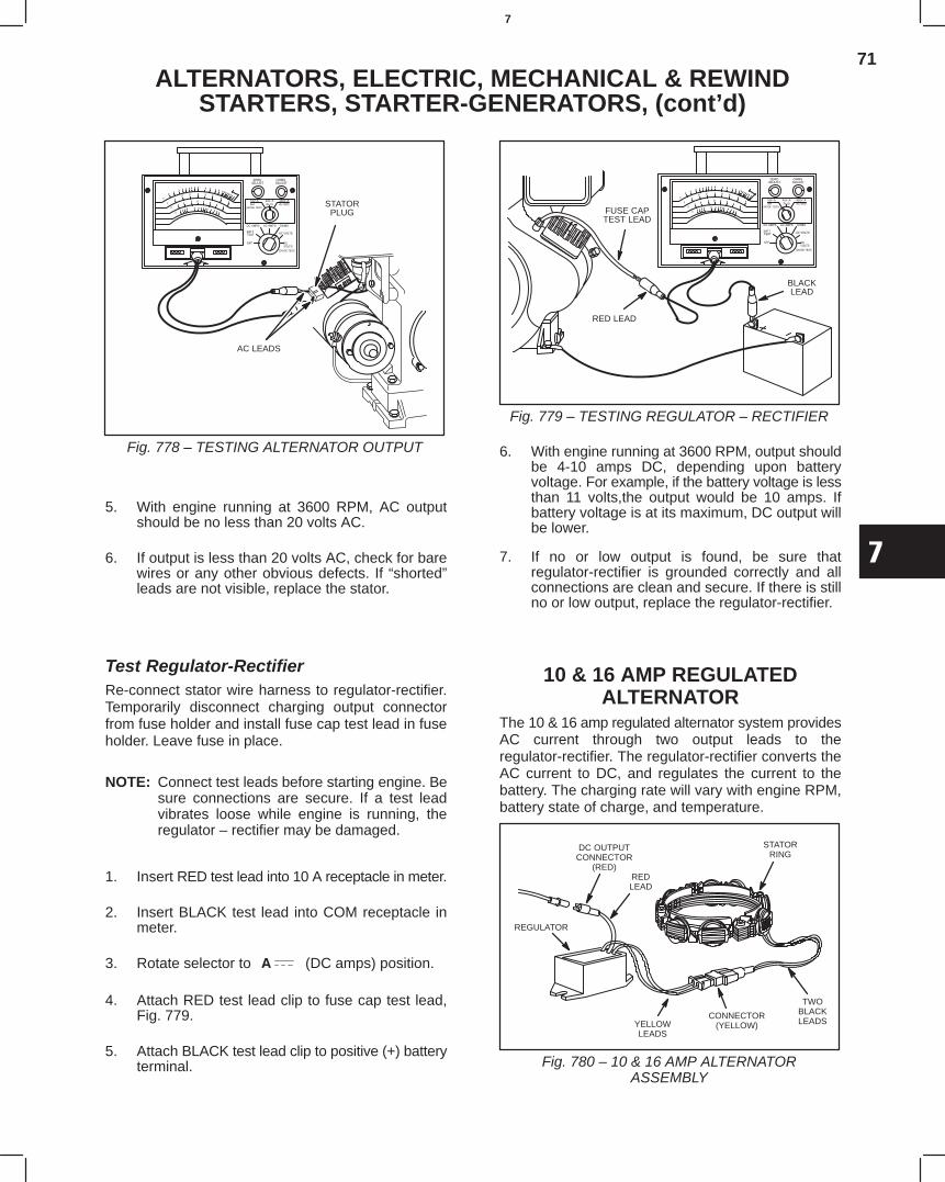
71
7
ALTERNATORS, ELECTRIC, MECHANICAL & REWINDSTARTERS, STARTER-GENERATORS, (cont’d)
Fig. 778 – TESTING ALTERNATOR OUTPUT
STATORPLUG
AC LEADS
5. With engine running at 3600 RPM, AC outputshould be no less than 20 volts AC.
6. If output is less than 20 volts AC, check for barewires or any other obvious defects. If “shorted”leads are not visible, replace the stator.
Test Regulator-RectifierRe-connect stator wire harness to regulator-rectifier.Temporarily disconnect charging output connectorfrom fuse holder and install fuse cap test lead in fuseholder. Leave fuse in place.
NOTE: Connect test leads before starting engine. Besure connections are secure. If a test leadvibrates loose while engine is running, theregulator – rectifier may be damaged.
1. Insert RED test lead into 10 A receptacle in meter.
2. Insert BLACK test lead into COM receptacle inmeter.
3. Rotate selector to (DC amps) position.
4. Attach RED test lead clip to fuse cap test lead,Fig. 779.
5. Attach BLACK test lead clip to positive (+) batteryterminal.
Fig. 779 – TESTING REGULATOR – RECTIFIER
FUSE CAPTEST LEAD
RED LEAD
BLACKLEAD
6. With engine running at 3600 RPM, output shouldbe 4-10 amps DC, depending upon batteryvoltage. For example, if the battery voltage is lessthan 11 volts,the output would be 10 amps. Ifbattery voltage is at its maximum, DC output willbe lower.
7. If no or low output is found, be sure thatregulator-rectifier is grounded correctly and allconnections are clean and secure. If there is stillno or low output, replace the regulator-rectifier.
10 & 16 AMP REGULATEDALTERNATOR
The 10 & 16 amp regulated alternator system providesAC current through two output leads to theregulator-rectifier. The regulator-rectifier converts theAC current to DC, and regulates the current to thebattery. The charging rate will vary with engine RPM,battery state of charge, and temperature.
REGULATOR
YELLOWLEADS
TWOBLACKLEADS
REDLEAD
DC OUTPUTCONNECTOR
(RED)
STATORRING
CONNECTOR(YELLOW)
Fig. 780 – 10 & 16 AMP ALTERNATORASSEMBLY
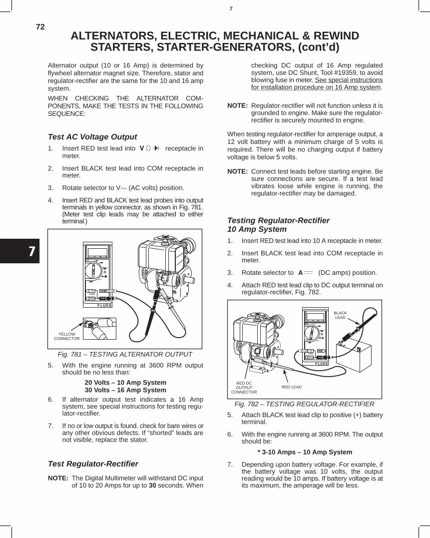
72
7
ALTERNATORS, ELECTRIC, MECHANICAL & REWINDSTARTERS, STARTER-GENERATORS, (cont’d)
Alternator output (10 or 16 Amp) is determined byflywheel alternator magnet size. Therefore, stator andregulator-rectifier are the same for the 10 and 16 ampsystem.
WHEN CHECKING THE ALTERNATOR COM-PONENTS, MAKE THE TESTS IN THE FOLLOWINGSEQUENCE:
Test AC Voltage Output1. Insert RED test lead into receptacle in
meter.
2. Insert BLACK test lead into COM receptacle inmeter.
3. Rotate selector to V (AC volts) position.
4. Insert RED and BLACK test lead probes into outputterminals in yellow connector, as shown in Fig. 781.(Meter test clip leads may be attached to eitherterminal.)
YELLOWCONNECTOR
Fig. 781 – TESTING ALTERNATOR OUTPUT
5. With the engine running at 3600 RPM outputshould be no less than:
20 Volts – 10 Amp System30 Volts – 16 Amp System
6. If alternator output test indicates a 16 Ampsystem, see special instructions for testing regu-lator-rectifier.
7. If no or low output is found. check for bare wires orany other obvious defects. If “shorted” leads arenot visible, replace the stator.
Test Regulator-Rectifier
NOTE: The Digital Multimeter will withstand DC inputof 10 to 20 Amps for up to 30 seconds. When
checking DC output of 16 Amp regulatedsystem, use DC Shunt, Tool #19359, to avoidblowing fuse in meter. See special instructionsfor installation procedure on 16 Amp system.
NOTE: Regulator-rectifier will not function unless it isgrounded to engine. Make sure the regulator-rectifier is securely mounted to engine.
When testing regulator-rectifier for amperage output, a12 volt battery with a minimum charge of 5 volts isrequired. There will be no charging output if batteryvoltage is below 5 volts.
NOTE: Connect test leads before starting engine. Besure connections are secure. If a test leadvibrates loose while engine is running, theregulator-rectifier may be damaged.
Testing Regulator-Rectifier10 Amp System1. Insert RED test lead into 10 A receptacle in meter.
2. Insert BLACK test lead into COM receptacle inmeter.
3. Rotate selector to (DC amps) position.
4. Attach RED test lead clip to DC output terminal onregulator-rectifier, Fig. 782.
BLACKLEAD
RED LEADRED DCOUTPUT
CONNECTOR
Fig. 782 – TESTING REGULATOR-RECTIFIER
5. Attach BLACK test lead clip to positive (+) batteryterminal.
6. With the engine running at 3600 RPM. The outputshould be:
* 3-10 Amps – 10 Amp System
7. Depending upon battery voltage. For example, ifthe battery voltage was 10 volts, the outputreading would be 10 amps. If battery voltage is atits maximum, the amperage will be less.
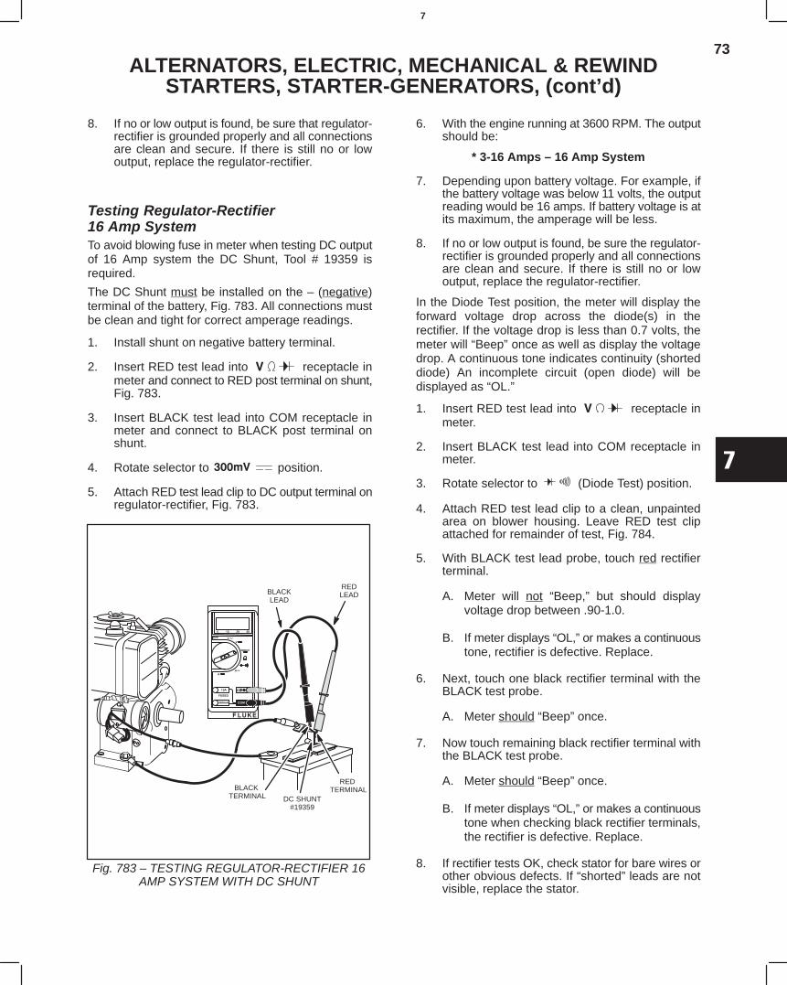
73
7
ALTERNATORS, ELECTRIC, MECHANICAL & REWINDSTARTERS, STARTER-GENERATORS, (cont’d)
8. If no or low output is found, be sure that regulator-rectifier is grounded properly and all connectionsare clean and secure. If there is still no or lowoutput, replace the regulator-rectifier.
Testing Regulator-Rectifier16 Amp SystemTo avoid blowing fuse in meter when testing DC outputof 16 Amp system the DC Shunt, Tool # 19359 isrequired.
The DC Shunt must be installed on the – (negative)terminal of the battery, Fig. 783. All connections mustbe clean and tight for correct amperage readings.
1. Install shunt on negative battery terminal.
2. Insert RED test lead into receptacle inmeter and connect to RED post terminal on shunt,Fig. 783.
3. Insert BLACK test lead into COM receptacle inmeter and connect to BLACK post terminal onshunt.
4. Rotate selector to position.
5. Attach RED test lead clip to DC output terminal onregulator-rectifier, Fig. 783.
Fig. 783 – TESTING REGULATOR-RECTIFIER 16AMP SYSTEM WITH DC SHUNT
REDLEADBLACK
LEAD
RED TERMINALBLACK
TERMINAL DC SHUNT#19359
6. With the engine running at 3600 RPM. The outputshould be:
* 3-16 Amps – 16 Amp System
7. Depending upon battery voltage. For example, ifthe battery voltage was below 11 volts, the outputreading would be 16 amps. If battery voltage is atits maximum, the amperage will be less.
8. If no or low output is found, be sure the regulator-rectifier is grounded properly and all connectionsare clean and secure. If there is still no or lowoutput, replace the regulator-rectifier.
In the Diode Test position, the meter will display theforward voltage drop across the diode(s) in therectifier. If the voltage drop is less than 0.7 volts, themeter will “Beep” once as well as display the voltagedrop. A continuous tone indicates continuity (shorteddiode) An incomplete circuit (open diode) will bedisplayed as “OL.”
1. Insert RED test lead into receptacle inmeter.
2. Insert BLACK test lead into COM receptacle inmeter.
3. Rotate selector to (Diode Test) position.
4. Attach RED test lead clip to a clean, unpaintedarea on blower housing. Leave RED test clipattached for remainder of test, Fig. 784.
5. With BLACK test lead probe, touch red rectifierterminal.
A. Meter will not “Beep,” but should displayvoltage drop between .90-1.0.
B. If meter displays “OL,” or makes a continuoustone, rectifier is defective. Replace.
6. Next, touch one black rectifier terminal with theBLACK test probe.
A. Meter should “Beep” once.
7. Now touch remaining black rectifier terminal withthe BLACK test probe.
A. Meter should “Beep” once.
B. If meter displays “OL,” or makes a continuoustone when checking black rectifier terminals,the rectifier is defective. Replace.
8. If rectifier tests OK, check stator for bare wires orother obvious defects. If “shorted” leads are notvisible, replace the stator.
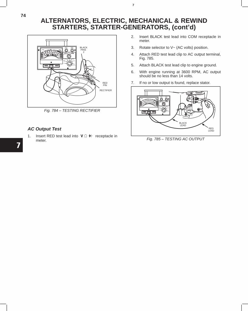
74
7
ALTERNATORS, ELECTRIC, MECHANICAL & REWINDSTARTERS, STARTER-GENERATORS, (cont’d)
Fig. 784 – TESTING RECTIFIER
REDPIN
BLACKPINS
2
RECTIFIER
AC Output Test1. Insert RED test lead into receptacle in
meter.
2. Insert BLACK test lead into COM receptacle inmeter.
3. Rotate selector to V~ (AC volts) position.
4. Attach RED test lead clip to AC output terminal,Fig. 785.
5. Attach BLACK test lead clip to engine ground.
6. With engine running at 3600 RPM, AC outputshould be no less than 14 volts.
7. If no or low output is found, replace stator.
Fig. 785 – TESTING AC OUTPUT
BLACKLEAD
REDLEAD
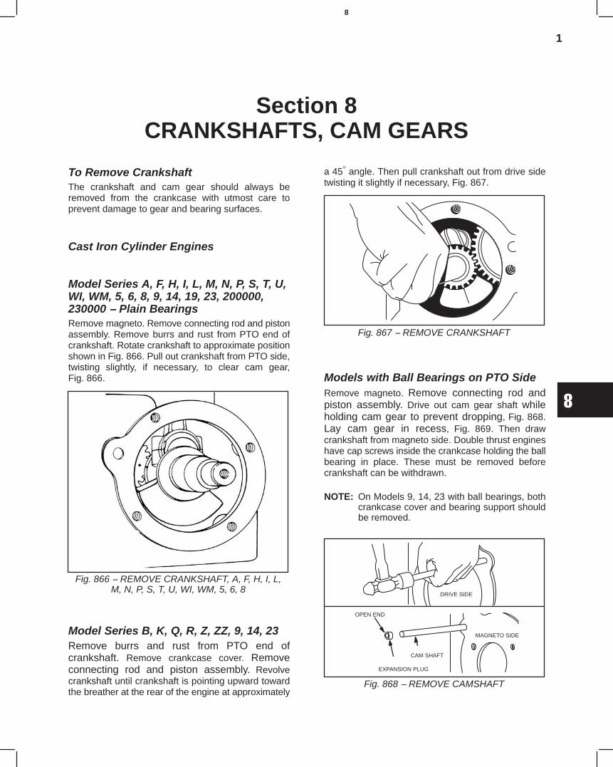
1
8
Section 8CRANKSHAFTS, CAM GEARS
To Remove CrankshaftThe crankshaft and cam gear should always beremoved from the crankcase with utmost care toprevent damage to gear and bearing surfaces.
Cast Iron Cylinder Engines
Model Series A, F, H, I, L, M, N, P, S, T, U,WI, WM, 5, 6, 8, 9, 14, 19, 23, 200000,230000 − Plain BearingsRemove magneto. Remove connecting rod and pistonassembly. Remove burrs and rust from PTO end ofcrankshaft. Rotate crankshaft to approximate positionshown in Fig. 866. Pull out crankshaft from PTO side,twisting slightly, if necessary, to clear cam gear,Fig. 866.
Fig. 866 − REMOVE CRANKSHAFT, A, F, H, I, L,M, N, P, S, T, U, WI, WM, 5, 6, 8
Model Series B, K, Q, R, Z, ZZ, 9, 14, 23Remove burrs and rust from PTO end ofcrankshaft. Remove crankcase cover. Removeconnecting rod and piston assembly. Revolvecrankshaft until crankshaft is pointing upward towardthe breather at the rear of the engine at approximately
a 45° angle. Then pull crankshaft out from drive sidetwisting it slightly if necessary, Fig. 867.
Fig. 867 − REMOVE CRANKSHAFT
Models with Ball Bearings on PTO SideRemove magneto. Remove connecting rod andpiston assembly. Drive out cam gear shaft whileholding cam gear to prevent dropping, Fig. 868.Lay cam gear in recess, Fig. 869. Then drawcrankshaft from magneto side. Double thrust engineshave cap screws inside the crankcase holding the ballbearing in place. These must be removed beforecrankshaft can be withdrawn.
NOTE: On Models 9, 14, 23 with ball bearings, bothcrankcase cover and bearing support shouldbe removed.
Fig. 868 − REMOVE CAMSHAFT
DRIVE SIDE
EXPANSION PLUG
OPEN END
MAGNETO SIDE
CAM SHAFT
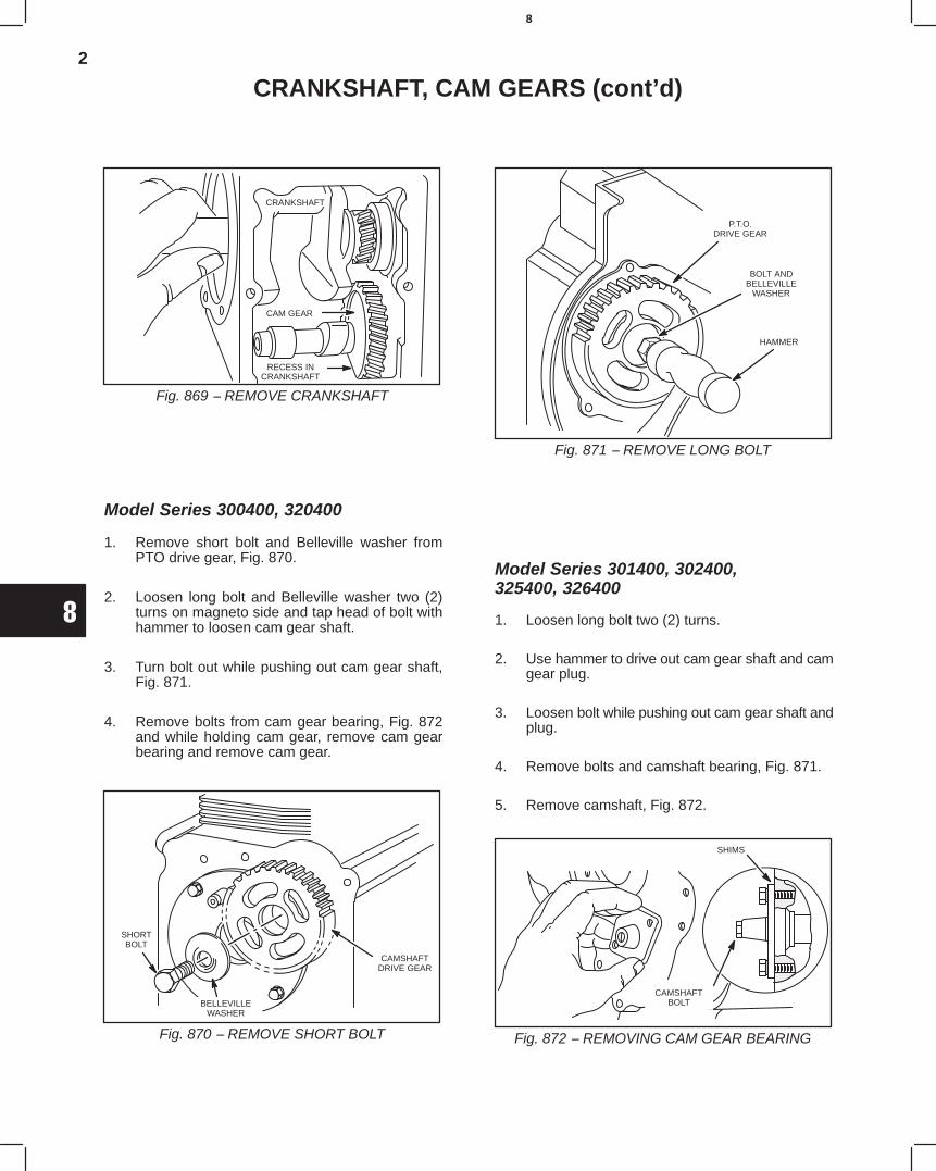
2
8
CRANKSHAFT, CAM GEARS (cont’d)
Fig. 869 − REMOVE CRANKSHAFT
RECESS INCRANKSHAFT
CAM GEAR
CRANKSHAFT
Model Series 300400, 320400
1. Remove short bolt and Belleville washer fromPTO drive gear, Fig. 870.
2. Loosen long bolt and Belleville washer two (2)turns on magneto side and tap head of bolt withhammer to loosen cam gear shaft.
3. Turn bolt out while pushing out cam gear shaft,Fig. 871.
4. Remove bolts from cam gear bearing, Fig. 872and while holding cam gear, remove cam gearbearing and remove cam gear.
Fig. 870 − REMOVE SHORT BOLT
CAMSHAFTDRIVE GEAR
SHORTBOLT
BELLEVILLEWASHER
Fig. 871 − REMOVE LONG BOLT
BOLT ANDBELLEVILLE
WASHER
P.T.O.DRIVE GEAR
HAMMER
Model Series 301400, 302400,325400, 326400
1. Loosen long bolt two (2) turns.
2. Use hammer to drive out cam gear shaft and camgear plug.
3. Loosen bolt while pushing out cam gear shaft andplug.
4. Remove bolts and camshaft bearing, Fig. 871.
5. Remove camshaft, Fig. 872.
Fig. 872 − REMOVING CAM GEAR BEARING
SHIMS
CAMSHAFTBOLT
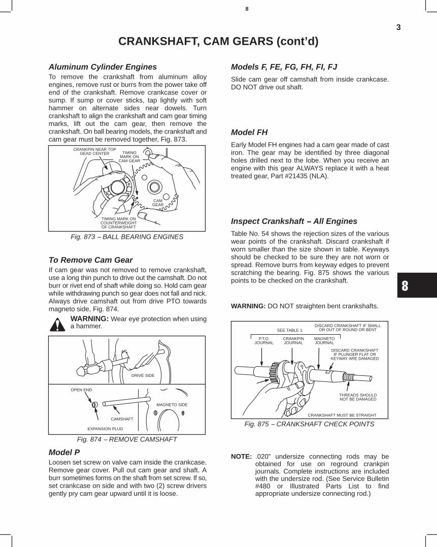
3
8
CRANKSHAFT, CAM GEARS (cont’d)
Aluminum Cylinder EnginesTo remove the crankshaft from aluminum alloyengines, remove rust or burrs from the power take offend of the crankshaft. Remove crankcase cover orsump. If sump or cover sticks, tap lightly with softhammer on alternate sides near dowels. Turncrankshaft to align the crankshaft and cam gear timingmarks, lift out the cam gear, then remove thecrankshaft. On ball bearing models, the crankshaft andcam gear must be removed together, Fig. 873.
Fig. 873 − BALL BEARING ENGINES
TIMING MARK ONCOUNTERWEIGHTOF CRANKSHAFT
TIMINGMARK ON
CAM GEAR
CRANKPIN NEAR TOPDEAD CENTER
CAMGEAR
To Remove Cam GearIf cam gear was not removed to remove crankshaft,use a long thin punch to drive out the camshaft. Do notburr or rivet end of shaft while doing so. Hold cam gearwhile withdrawing punch so gear does not fall and nick.Always drive camshaft out from drive PTO towardsmagneto side, Fig. 874.
WARNING: Wear eye protection when usinga hammer.
Fig. 874 − REMOVE CAMSHAFT
DRIVE SIDE
EXPANSION PLUG
OPEN END
MAGNETO SIDE
CAMSHAFT
Model PLoosen set screw on valve cam inside the crankcase.Remove gear cover. Pull out cam gear and shaft. Aburr sometimes forms on the shaft from set screw. If so,set crankcase on side and with two (2) screw driversgently pry cam gear upward until it is loose.
Models F, FE, FG, FH, FI, FJSlide cam gear off camshaft from inside crankcase.DO NOT drive out shaft.
Model FHEarly Model FH engines had a cam gear made of castiron. The gear may be identified by three diagonalholes drilled next to the lobe. When you receive anengine with this gear ALWAYS replace it with a heattreated gear, Part #21435 (NLA).
Inspect Crankshaft − All EnginesTable No. 54 shows the rejection sizes of the variouswear points of the crankshaft. Discard crankshaft ifworn smaller than the size shown in table. Keywaysshould be checked to be sure they are not worn orspread. Remove burrs from keyway edges to preventscratching the bearing. Fig. 875 shows the variouspoints to be checked on the crankshaft.
WARNING: DO NOT straighten bent crankshafts.
Fig. 875 − CRANKSHAFT CHECK POINTSCRANKSHAFT MUST BE STRAIGHT
THREADS SHOULDNOT BE DAMAGED
DISCARD CRANKSHAFTIF PLUNGER FLAT OR
KEYWAY ARE DAMAGED
DISCARD CRANKSHAFT IF SMALLOR OUT OF ROUND OR BENT
P.T.O.JOURNAL
CRANKPINJOURNAL
MAGNETOJOURNAL
SEE TABLE 1
NOTE: .020” undersize connecting rods may beobtained for use on reground crankpinjournals. Complete instructions are includedwith the undersize rod. (See Service Bulletin#480 or Illustrated Parts List to findappropriate undersize connecting rod.)
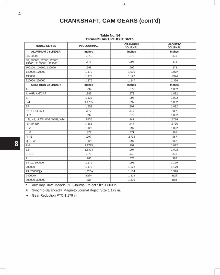
4
8
CRANKSHAFT, CAM GEARS (cont’d)
Table No. 54CRANKSHAFT REJECT SIZES
MODEL SERIES PTO JOURNAL CRANKPINJOURNAL
MAGNETOJOURNAL
ALUMINUM CYLINDER Inches Inches Inches
6B, 60000 .873 .870 .873
8B, 80000*, 82000, 92000*,93000*, 110900*, 111900* .873 .996 .873
100200, 100900, 130000 .998 .996 .873
140000, 170000 1.179 1.090 .997#
190000 1.179 1.122 .997#
220000, 250000 1.376 1.247 1.376
CAST IRON CYLINDER Inches Inches Inches
A .992 .872 1.092
A, AHP, AMT, AP .983 .872 1.092
B 1.122 .997 1.092
BM 1.1795 .997 1.092
BP 1.803 .997 1.092
FH, FI, FJ, S, T .872 .872 .967
H, Y .992 .872 1.092
I, N, NS, U, WI, WM, WMB, WMI .8736 .747 .8736
IBP, IP, NP .7863 .747 .8736
K, Z 1.122 .997 1.092
L, M .872 .871 .967
P, PB .997 .8715 .967
Q, R, W 1.122 .997 .967
ZM 1.1795 .997 1.092
ZZ 1.1803 .997 1.092
5, 6, 8 .873 .743 .873
9 .983 .873 .983
14, 19, 190000 1.179 .996 1.179
200000 1.179 1.122 1.179
23, 230000 ♦ 1.376♦ 1.184 1.376
240000♦ Ball♦ 1.309 Ball
300000, 320000 Ball 1.309 Ball
* Auxiliary Drive Models PTO Journal Reject Size 1.003 in.
# Synchro-Balanced Magneto Journal Reject Size 1.179 in.
♦ Gear Reduction PTO 1.179 in.
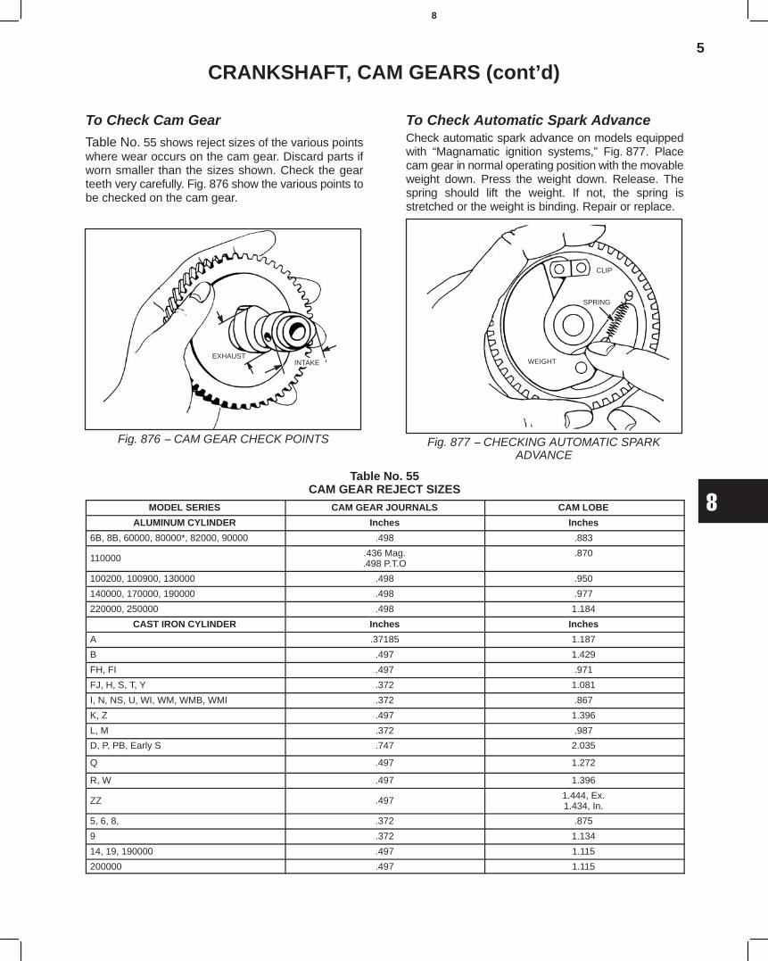
5
8
CRANKSHAFT, CAM GEARS (cont’d)
To Check Cam Gear
Table No. 55 shows reject sizes of the various pointswhere wear occurs on the cam gear. Discard parts ifworn smaller than the sizes shown. Check the gearteeth very carefully. Fig. 876 show the various points tobe checked on the cam gear.
Fig. 876 − CAM GEAR CHECK POINTS
EXHAUSTINTAKE
To Check Automatic Spark AdvanceCheck automatic spark advance on models equippedwith “Magnamatic ignition systems,” Fig. 877. Placecam gear in normal operating position with the movableweight down. Press the weight down. Release. Thespring should lift the weight. If not, the spring isstretched or the weight is binding. Repair or replace.
Fig. 877 − CHECKING AUTOMATIC SPARKADVANCE
CLIP
SPRING
WEIGHT
Table No. 55CAM GEAR REJECT SIZES
MODEL SERIES CAM GEAR JOURNALS CAM LOBE
ALUMINUM CYLINDER Inches Inches
6B, 8B, 60000, 80000*, 82000, 90000 .498 .883
110000 .436 Mag..498 P.T.O
.870
100200, 100900, 130000 .498 .950
140000, 170000, 190000 .498 .977
220000, 250000 .498 1.184
CAST IRON CYLINDER Inches Inches
A .37185 1.187
B .497 1.429
FH, FI .497 .971
FJ, H, S, T, Y .372 1.081
I, N, NS, U, WI, WM, WMB, WMI .372 .867
K, Z .497 1.396
L, M .372 .987
D, P, PB, Early S .747 2.035
Q .497 1.272
R, W .497 1.396
ZZ .497 1.444, Ex.1.434, In.
5, 6, 8, .372 .875
9 .372 1.134
14, 19, 190000 .497 1.115
200000 .497 1.115
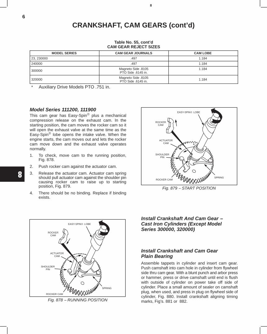
6
8
CRANKSHAFT, CAM GEARS (cont’d)
Table No. 55, cont’dCAM GEAR REJECT SIZES
MODEL SERIES CAM GEAR JOURNALS CAM LOBE
23, 230000 .497 1.184
240000 .497 1.184
300000 Magneto Side .8105PTO Side .6145 in.
1.184
320000 Magneto Side .8105PTO Side .6145 in. 1.184
* Auxiliary Drive Models PTO .751 in.
Model Series 111200, 111900This cam gear has Easy-Spin plus a mechanicalcompression release on the exhaust cam. In thestarting position, the cam moves the rocker cam so itwill open the exhaust valve at the same time as theEasy-Spin lobe opens the intake valve. When theengine starts, the cam moves out and lets the rockercam move down and the exhaust valve operatesnormally.
1. To check, move cam to the running position,Fig. 878.
2. Push rocker cam against the actuator cam.
3. Release the actuator cam. Actuator cam springshould pull actuator cam against the shoulder pincausing rocker cam to raise up to startingposition, Fig. 879.
4. There should be no binding. Replace if bindingexists.
Fig. 878 − RUNNING POSITION
EASY-SPIN LOBE
ROCKERCAM
SHOULDERPIN
ROCKER CAM
SPRING
ACTUATORCAM
Fig. 879 − START POSITION
EASY-SPIN LOBE
ROCKERCAM
ACTUATORCAM
SHOULDERPIN
ROCKER CAMSPRING
Install Crankshaft And Cam Gear − Cast Iron Cylinders (Except ModelSeries 300000, 320000)
Install Crankshaft and Cam GearPlain BearingAssemble tappets in cylinder and insert cam gear.Push camshaft into cam hole in cylinder from flywheelside thru cam gear. With a blunt punch and arbor pressor hammer, press or drive camshaft until end is flushwith outside of cylinder on power take off side ofcylinder. Place a small amount of sealer on camshaftplug, when used, and press in plug on flywheel side ofcylinder, Fig. 880. Install crankshaft aligning timingmarks, Fig’s. 881 or 882.
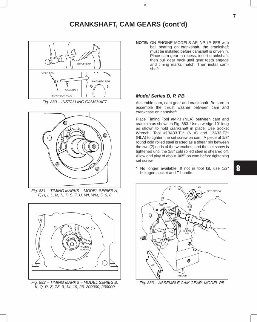
7
8
CRANKSHAFT, CAM GEARS (cont’d)
Fig. 880 − INSTALLING CAMSHAFT
DRIVE SIDE
EXPANSION PLUG
OPEN END
MAGNETO SIDE
CAMSHAFT
Fig. 881 − TIMING MARKS − MODEL SERIES A,F, H, I, L, M, N, P, S, T, U, WI, WM, 5, 6, 8
Fig. 882 − TIMING MARKS − MODEL SERIES B,K, Q, R, Z, ZZ, 9, 14, 19, 23, 200000, 230000
TIMINGMARKS
NOTE: ON ENGINE MODELS AP, NP, IP, 8FB withball bearing on crankshaft, the crankshaftmust be installed before camshaft is driven in.Place cam gear in recess, insert crankshaft,then pull gear back until gear teeth engageand timing marks match. Then install cam-shaft.
Model Series D, P, PBAssemble cam, cam gear and crankshaft. Be sure toassemble the thrust washer between cam andcrankcase on camshaft.
Place Timing Tool #MPJ (NLA) between cam andcrankpin as shown in Fig. 883. Use a wedge 10” longas shown to hold crankshaft in place. Use SocketWrench, Tool #13A33-T1* (NLA) and 13A33-T2*(NLA) to tighten the set screw on cam. A piece of 1/8”round cold rolled steel is used as a shear pin betweenthe two (2) ends of the wrenches, and the set screw istightened until the 1/8” cold rolled steel is sheared off.Allow end play of about .005” on cam before tighteningset screw.
* No longer available. If not in tool kit, use 1/2”hexagon socket and T-handle.
Fig. 883 − ASSEMBLE CAM GEAR, MODEL PB
CAM
SET SCREW
1/8”SHEAR
PIN
WEDGE
MPJ
MPJ
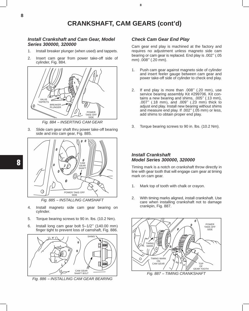
8
8
CRANKSHAFT, CAM GEARS (cont’d)
Install Crankshaft and Cam Gear, ModelSeries 300000, 3200001. Install breaker plunger (when used) and tappets.
2. Insert cam gear from power take-off side ofcylinder, Fig. 884.
Fig. 884 − INSERTING CAM GEAR
POWERTAKE-OFF
SIDE
VALVETAPPETS
BREAKERPLUNGER
3. Slide cam gear shaft thru power take-off bearingside and into cam gear, Fig. 885.
Fig. 885 − INSTALLING CAMSHAFT
POWER TAKE-OFFSIDE
CAMGEARSHAFT
4. Install magneto side cam gear bearing oncylinder.
5. Torque bearing screws to 90 in. lbs. (10.2 Nm).
6. Install long cam gear bolt 5−1/2" (140.00 mm)finger tight to prevent loss of camshaft, Fig. 886.
Fig. 886 − INSTALLING CAM GEAR BEARING
SHIMS
CAM GEARSHAFT BOLT
Check Cam Gear End Play
Cam gear end play is machined at the factory andrequires no adjustment unless magneto side cambearing or cam gear is replaced. End play is .002" (.05mm) .008" (.20 mm).
1. Push cam gear against magneto side of cylinderand insert feeler gauge between cam gear andpower take-off side of cylinder to check end play.
2. If end play is more than .008" (.20 mm), useservice bearing assembly Kit #299706. Kit con-tains a new bearing and shims, .005" (.13 mm),.007" (.18 mm), and .009" (.23 mm) thick toadjust end play. Install new bearing without shimsand measure end play. If .002" (.05 mm) or less,add shims to obtain proper end play.
3. Torque bearing screws to 90 in. lbs. (10.2 Nm).
Install CrankshaftModel Series 300000, 320000
Timing mark is a notch on crankshaft throw directly inline with gear tooth that will engage cam gear at timingmark on cam gear.
1. Mark top of tooth with chalk or crayon.
2. With timing marks aligned, install crankshaft. Usecare when installing crankshaft not to damagecrankpin, Fig. 887.
Fig. 887 − TIMING CRANKSHAFT
TIMING MARKON
CAM GEAR TOPOF
GEAR TOOTH
POWERTAKE-OFF
SIDE
TIMINGMARK
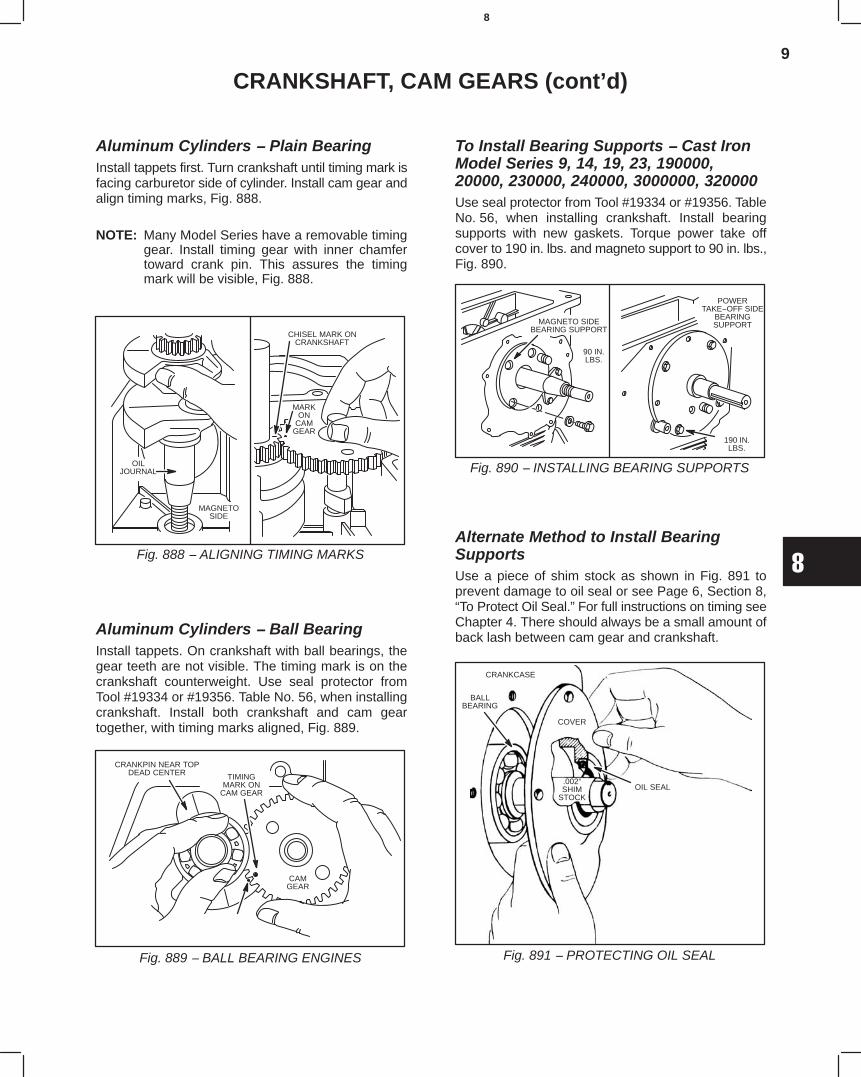
9
8
CRANKSHAFT, CAM GEARS (cont’d)
Aluminum Cylinders − Plain BearingInstall tappets first. Turn crankshaft until timing mark isfacing carburetor side of cylinder. Install cam gear andalign timing marks, Fig. 888.
NOTE: Many Model Series have a removable timinggear. Install timing gear with inner chamfertoward crank pin. This assures the timingmark will be visible, Fig. 888.
Fig. 888 − ALIGNING TIMING MARKS
MARKON
CAMGEAR
CHISEL MARK ONCRANKSHAFT
MAGNETOSIDE
OILJOURNAL
Aluminum Cylinders − Ball BearingInstall tappets. On crankshaft with ball bearings, thegear teeth are not visible. The timing mark is on thecrankshaft counterweight. Use seal protector fromTool #19334 or #19356. Table No. 56, when installingcrankshaft. Install both crankshaft and cam geartogether, with timing marks aligned, Fig. 889.
Fig. 889 − BALL BEARING ENGINES
TIMINGMARK ON
CAM GEAR
CRANKPIN NEAR TOPDEAD CENTER
CAMGEAR
To Install Bearing Supports − Cast IronModel Series 9, 14, 19, 23, 190000,20000, 230000, 240000, 3000000, 320000Use seal protector from Tool #19334 or #19356. TableNo. 56, when installing crankshaft. Install bearingsupports with new gaskets. Torque power take offcover to 190 in. lbs. and magneto support to 90 in. lbs.,Fig. 890.
Fig. 890 − INSTALLING BEARING SUPPORTS
MAGNETO SIDEBEARING SUPPORT
90 IN.LBS.
POWERTAKE−OFF SIDE
BEARINGSUPPORT
190 IN.LBS.
Alternate Method to Install BearingSupportsUse a piece of shim stock as shown in Fig. 891 toprevent damage to oil seal or see Page 6, Section 8,“To Protect Oil Seal.” For full instructions on timing seeChapter 4. There should always be a small amount ofback lash between cam gear and crankshaft.
Fig. 891 − PROTECTING OIL SEAL
CRANKCASE
COVER
OIL SEAL.002”SHIM
STOCK
BALLBEARING
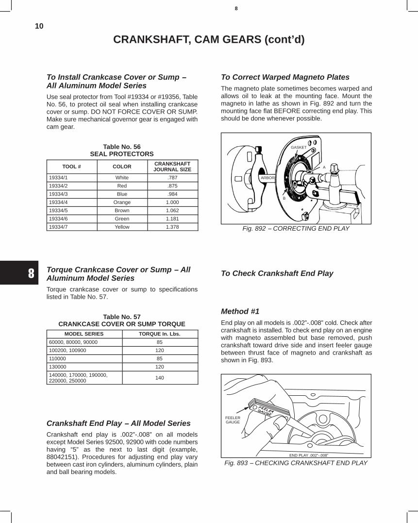
10
8
CRANKSHAFT, CAM GEARS (cont’d)
To Install Crankcase Cover or Sump −All Aluminum Model SeriesUse seal protector from Tool #19334 or #19356, TableNo. 56, to protect oil seal when installing crankcasecover or sump. DO NOT FORCE COVER OR SUMP.Make sure mechanical governor gear is engaged withcam gear.
Table No. 56SEAL PROTECTORS
TOOL # COLOR CRANKSHAFTJOURNAL SIZE
19334/1 White .787
19334/2 Red .875
19334/3 Blue .984
19334/4 Orange 1.000
19334/5 Brown 1.062
19334/6 Green 1.181
19334/7 Yellow 1.378
Torque Crankcase Cover or Sump − AllAluminum Model SeriesTorque crankcase cover or sump to specificationslisted in Table No. 57.
Table No. 57CRANKCASE COVER OR SUMP TORQUE
MODEL SERIES TORQUE In. Lbs.
60000, 80000, 90000 85
100200, 100900 120
110000 85
130000 120
140000, 170000, 190000,220000, 250000 140
Crankshaft End Play − All Model SeriesCrankshaft end play is .002”-.008” on all modelsexcept Model Series 92500, 92900 with code numbershaving “5” as the next to last digit (example,88042151). Procedures for adjusting end play varybetween cast iron cylinders, aluminum cylinders, plainand ball bearing models.
To Correct Warped Magneto PlatesThe magneto plate sometimes becomes warped andallows oil to leak at the mounting face. Mount themagneto in lathe as shown in Fig. 892 and turn themounting face flat BEFORE correcting end play. Thisshould be done whenever possible.
Fig. 892 − CORRECTING END PLAY
ARBOR
GASKET
B
A
To Check Crankshaft End Play
Method #1End play on all models is .002”-.008” cold. Check aftercrankshaft is installed. To check end play on an enginewith magneto assembled but base removed, pushcrankshaft toward drive side and insert feeler gaugebetween thrust face of magneto and crankshaft asshown in Fig. 893.
Fig. 893 − CHECKING CRANKSHAFT END PLAYEND PLAY .002”-.008”
FEELERGAUGE
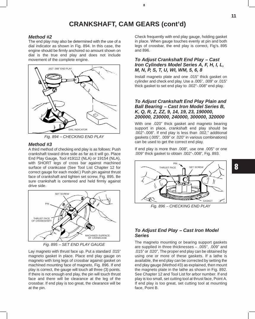
11
8
CRANKSHAFT, CAM GEARS (cont’d)
Method #2The end play may also be determined with the use of adial indicator as shown in Fig. 894. In this case, theengine should be firmly anchored so amount shown ondial is the true end play and does not includemovement of the complete engine.
Fig. 894 − CHECKING END PLAY
.002”-.088” END PLAY
DIAL INDICATOR
Method #3A third method of checking end play is as follows: Pushcrankshaft toward drive side as far as it will go. PlaceEnd Play Gauge, Tool #19112 (NLA) or 19154 (NLA),with SHORT legs of cross bar against machinedsurface of crankcase (See Tool List Chapter 12 forcorrect gauge for each model.) Push pin against thrustface of crankshaft and tighten set screw, Fig. 895. Besure crankshaft is centered and held firmly againstdrive side.
Fig. 895 − SET END PLAY GAUGE
SET SCREW
PIN
THRUST FACEOF CRANKSHAFT
MACHINED SURFACEOF CRANKCASE
Lay magneto with thrust face up. Put a standard .015”magneto gasket in place. Place end play gauge onmagneto with long legs of crossbar against gasket onmachined mounting face of magneto, Fig. 896. If endplay is correct, the gauge will touch all three (3) points.If there is not enough end play, the pin will touch thrustface and there will be clearance at the leg of thecrossbar. If end play is too great, the clearance will beat the pin.
Check frequently with end play gauge, holding gasketin place. When gauge touches evenly at pin and bothlegs of crossbar, the end play is correct, Fig’s. 895and 896.
To Adjust Crankshaft End Play − CastIron Cylinders Model Series A, F, H, I, L,M, N, P, S, T, U, WI, WM, 5, 6, 8Install magneto plate and one .015” thick gasket oncylinder and check end play. Use a .005”, .009” or .015”thick gasket to set end play to .002”-.008” end play.
To Adjust Crankshaft End Play Plain andBall Bearing − Cast Iron Model Series B,K, Q, R, Z, ZZ, 9, 14, 19, 23, 190000,200000, 230000, 240000, 300000, 320000With one .020” thick gasket and magneto bearingsupport in place, crankshaft end play should be.002”-.008”. If end play is less than .002,” additionalgaskets (.005”, .009” or .020” in various combinations)can be used to get the correct end play.
If end play is more than .008”, use one .005” or one.009” thick gasket to obtain .002”-.008”, Fig. 893.
Fig. 896 − CHECKING END PLAY
THRUST FACE
PIN
SET SCREW
GASKET
To Adjust End Play − Cast Iron ModelSeriesThe magneto mounting or bearing support gasketsare supplied in three thicknesses − .005”, .009” and.015” or .020”, The proper end play can be obtained byusing one or more of these gaskets. If a lathe isavailable, the end play can be corrected by setting theend play gauge (Method #3) as explained, then mountthe magneto plate in the lathe as shown in Fig. 892.See Chapter 12 and Tool List for arbor number. If endplay is too small, set cutting tool at thrust face, Point A.If end play is too great, set cutting tool at mountingface, Point B.
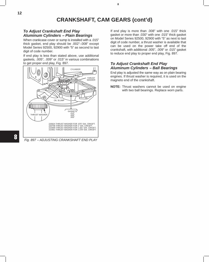
12
8
CRANKSHAFT, CAM GEARS (cont’d)
To Adjust Crankshaft End PlayAluminum Cylinders − Plain BearingsWhen crankcase cover or sump is installed with a .015”thick gasket, end play should be .002”-.008” exceptModel Series 92500, 92900 with “5” as second to lastdigit of code number.If end play is less than stated above, use additionalgaskets, .005”, .009” or .015” in various combinationsto get proper end play, Fig. 897.
Fig. 897 − ADJUSTING CRANKSHAFT END PLAY
220624 THRUST WASHER FOR .875” DIA. CRKSFT.220708 THRUST WASHER FOR 1” DIA. CRKSFT.222949 THRUST WASHER FOR 1.181” DIA. CRKSFT.222951 THRUST WASHER FOR 1.378” DIA. CRKSFT.
GASKETS.015”.009”.005”
THRUSTWASHER
THRUST WASHER
OIL SLUMP
CYLINDER
If end play is more than .008” with one .015” thickgasket or more than .030” with one .015” thick gasketon Model Series 92500, 92900 with “5” as next to lastdigit of code number, a thrust washer is available thatcan be used on the power take off end of thecrankshaft, with additional .005”, .009” or .015” gasketto reduce end play to proper end play, Fig. 897.
To Adjust Crankshaft End PlayAluminum Cylinders − Ball BearingsEnd play is adjusted the same way as on plain bearingengines. If thrust washer is required, it is used on themagneto end of the crankshaft.
NOTE: Thrust washers cannot be used on enginewith two ball bearings. Replace worn parts.
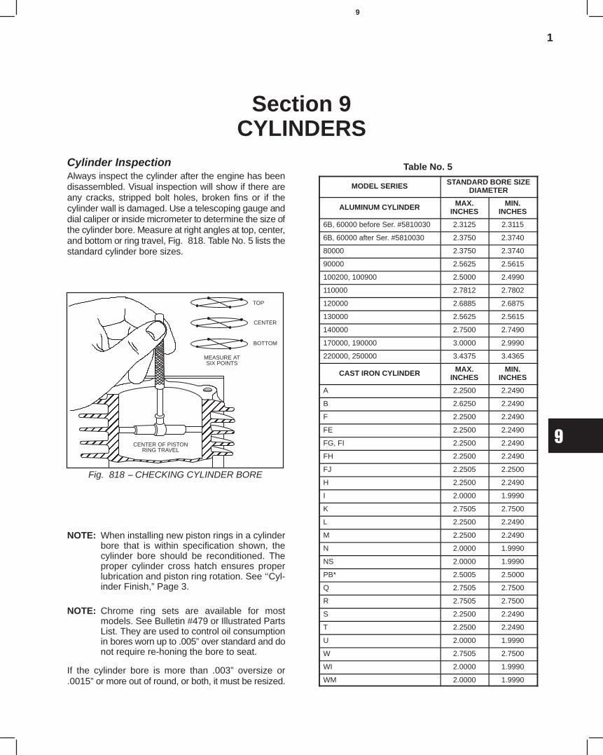
1
9
Section 9CYLINDERS
Cylinder InspectionAlways inspect the cylinder after the engine has beendisassembled. Visual inspection will show if there areany cracks, stripped bolt holes, broken fins or if thecylinder wall is damaged. Use a telescoping gauge anddial caliper or inside micrometer to determine the size ofthe cylinder bore. Measure at right angles at top, center,and bottom or ring travel, Fig. 818. Table No. 5 lists thestandard cylinder bore sizes.
ÉÉÉÉÉÉÉÉÉÉÉÉÉÉÉÉÉÉÉÉÉÉÉÉÉÉÉÉÉÉÉÉÉÉÉÉÉÉÉÉÉÉÉÉÉÉÉÉÉÉÉÉÉÉÉÉÉÉÉÉÉÉÉÉÉÉÉÉÉÉÉÉ
MEASURE ATSIX POINTS
CENTER OF PISTONRING TRAVEL
Fig. 818 − CHECKING CYLINDER BORE
TOP
BOTTOM
CENTER
NOTE: When installing new piston rings in a cylinderbore that is within specification shown, thecylinder bore should be reconditioned. Theproper cylinder cross hatch ensures properlubrication and piston ring rotation. See ‘‘Cyl-inder Finish,” Page 3.
NOTE: Chrome ring sets are available for mostmodels. See Bulletin #479 or Illustrated PartsList. They are used to control oil consumptionin bores worn up to .005” over standard and donot require re-honing the bore to seat.
If the cylinder bore is more than .003” oversize or.0015” or more out of round, or both, it must be resized.
Table No. 5
MODEL SERIES STANDARD BORE SIZEDIAMETER
ALUMINUM CYLINDER MAX.INCHES
MIN.INCHES
6B, 60000 before Ser. #5810030 2.3125 2.3115
6B, 60000 after Ser. #5810030 2.3750 2.3740
80000 2.3750 2.3740
90000 2.5625 2.5615
100200, 100900 2.5000 2.4990
110000 2.7812 2.7802
120000 2.6885 2.6875
130000 2.5625 2.5615
140000 2.7500 2.7490
170000, 190000 3.0000 2.9990
220000, 250000 3.4375 3.4365
CAST IRON CYLINDER MAX.INCHES
MIN.INCHES
A 2.2500 2.2490
B 2.6250 2.2490
F 2.2500 2.2490
FE 2.2500 2.2490
FG, FI 2.2500 2.2490
FH 2.2500 2.2490
FJ 2.2505 2.2500
H 2.2500 2.2490
I 2.0000 1.9990
K 2.7505 2.7500
L 2.2500 2.2490
M 2.2500 2.2490
N 2.0000 1.9990
NS 2.0000 1.9990
PB* 2.5005 2.5000
Q 2.7505 2.7500
R 2.7505 2.7500
S 2.2500 2.2490
T 2.2500 2.2490
U 2.0000 1.9990
W 2.7505 2.7500
WI 2.0000 1.9990
WM 2.0000 1.9990
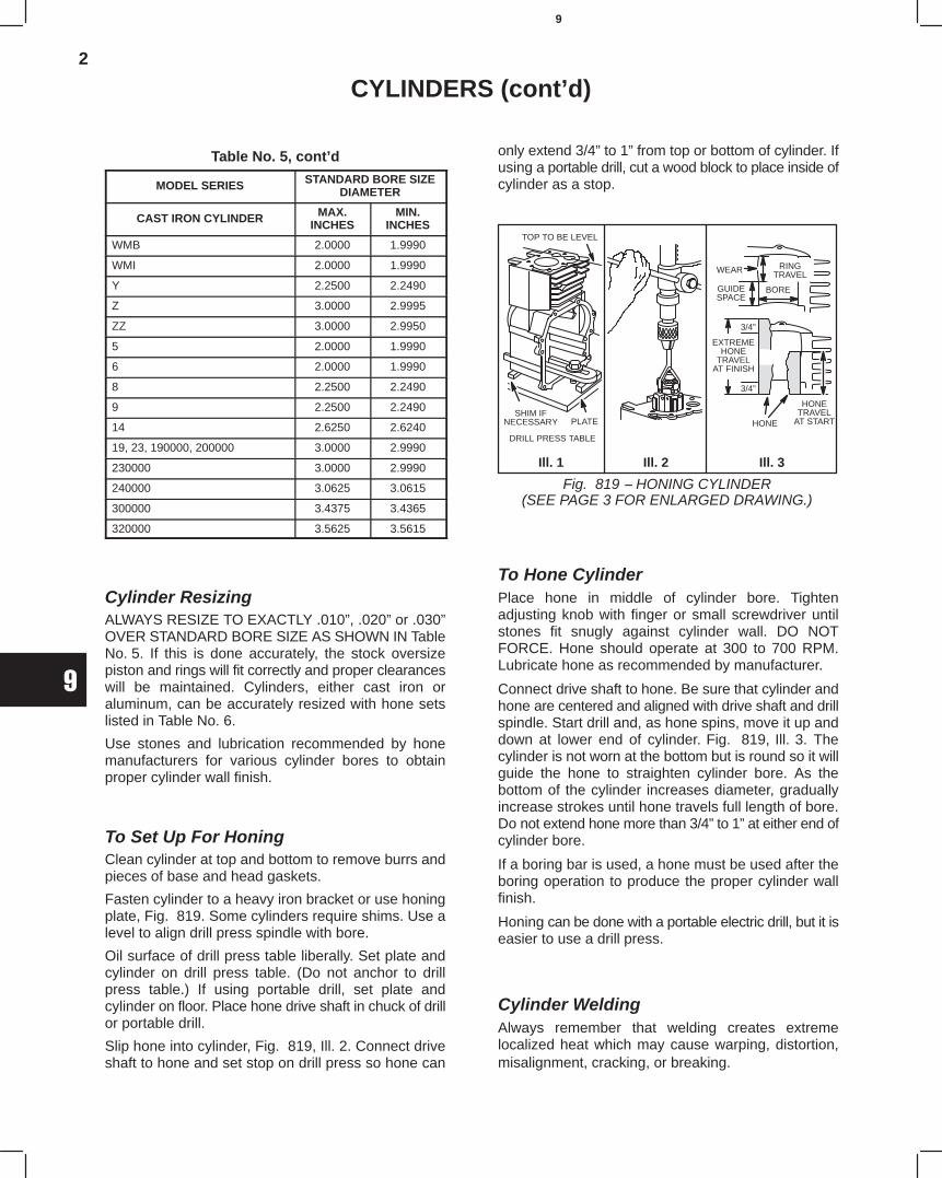
2
9
CYLINDERS (cont’d)
Table No. 5, cont’d
MODEL SERIES STANDARD BORE SIZEDIAMETER
CAST IRON CYLINDER MAX.INCHES
MIN.INCHES
WMB 2.0000 1.9990
WMI 2.0000 1.9990
Y 2.2500 2.2490
Z 3.0000 2.9995
ZZ 3.0000 2.9950
5 2.0000 1.9990
6 2.0000 1.9990
8 2.2500 2.2490
9 2.2500 2.2490
14 2.6250 2.6240
19, 23, 190000, 200000 3.0000 2.9990
230000 3.0000 2.9990
240000 3.0625 3.0615
300000 3.4375 3.4365
320000 3.5625 3.5615
Cylinder ResizingALWAYS RESIZE TO EXACTLY .010”, .020” or .030”OVER STANDARD BORE SIZE AS SHOWN IN TableNo. 5. If this is done accurately, the stock oversizepiston and rings will fit correctly and proper clearanceswill be maintained. Cylinders, either cast iron oraluminum, can be accurately resized with hone setslisted in Table No. 6.
Use stones and lubrication recommended by honemanufacturers for various cylinder bores to obtainproper cylinder wall finish.
To Set Up For HoningClean cylinder at top and bottom to remove burrs andpieces of base and head gaskets.
Fasten cylinder to a heavy iron bracket or use honingplate, Fig. 819. Some cylinders require shims. Use alevel to align drill press spindle with bore.
Oil surface of drill press table liberally. Set plate andcylinder on drill press table. (Do not anchor to drillpress table.) If using portable drill, set plate andcylinder on floor. Place hone drive shaft in chuck of drillor portable drill.
Slip hone into cylinder, Fig. 819, Ill. 2. Connect driveshaft to hone and set stop on drill press so hone can
only extend 3/4” to 1” from top or bottom of cylinder. Ifusing a portable drill, cut a wood block to place inside ofcylinder as a stop.
TOP TO BE LEVEL
WEAR
GUIDESPACE
RINGTRAVEL
BORE
HONETRAVEL
AT START
EXTREMEHONE
TRAVELAT FINISH
3/4”
3/4”
HONE
DRILL PRESS TABLE
SHIM IFNECESSARY PLATE
Fig. 819 − HONING CYLINDER(SEE PAGE 3 FOR ENLARGED DRAWING.)
Ill. 1 Ill. 2 Ill. 3
To Hone CylinderPlace hone in middle of cylinder bore. Tightenadjusting knob with finger or small screwdriver untilstones fit snugly against cylinder wall. DO NOTFORCE. Hone should operate at 300 to 700 RPM.Lubricate hone as recommended by manufacturer.
Connect drive shaft to hone. Be sure that cylinder andhone are centered and aligned with drive shaft and drillspindle. Start drill and, as hone spins, move it up anddown at lower end of cylinder. Fig. 819, Ill. 3. Thecylinder is not worn at the bottom but is round so it willguide the hone to straighten cylinder bore. As thebottom of the cylinder increases diameter, graduallyincrease strokes until hone travels full length of bore.Do not extend hone more than 3/4” to 1” at either end ofcylinder bore.
If a boring bar is used, a hone must be used after theboring operation to produce the proper cylinder wallfinish.
Honing can be done with a portable electric drill, but it iseasier to use a drill press.
Cylinder WeldingAlways remember that welding creates extremelocalized heat which may cause warping, distortion,misalignment, cracking, or breaking. 3360
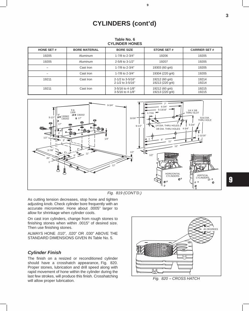
3
9
CYLINDERS (cont’d)
Table No. 6CYLINDER HONES
HONE SET # BORE MATERIAL BORE SIZE STONE SET # CARRIER SET #
19205 Aluminum 1-7/8 to 2-3/4” 19206 19205
19205 Aluminum 2-5/8 to 3-1/2” 19207 19205
− Cast Iron 1-7/8 to 2-3/4” 19303 (60 grit) 19205
− Cast Iron 1-7/8 to 2-3/4” 19304 (220 grit) 19205
19211 Cast Iron 2-1/2 to 3-5/16”2-1/2 to 3-5/16”
19212 (60 grit)19213 (220 grit)
1921419214
19211 Cast Iron 3-5/16 to 4-1/8”3-5/16 to 4-1/8”
19212 (60 grit)19213 (220 grit)
1921519215
HORIZONTALCYLINDERS VERTICAL
CYLINDERS
5/16 DIA.THRU HOLE
1-11/16”
12”
11”
1/2”
6”1
1/4 DIA. THRU HOLES
1/4 X 3/8THRU SLOT
11/16”
7”6-3/4”
5-13/16”1-7/16
9-1/2”4-3/4”
5-3/4”
1/2”
3”
3”
9-1/2”
1/4”
20”6”
11”
1”
3-7/8”
12”
1/2”
9-3/4”
9”
17”
9 &1309
130202
17”130902130202
Fig. 819 (CONT’D.)
3/8 DIA. THRU HOLES
As cutting tension decreases, stop hone and tightenadjusting knob. Check cylinder bore frequently with anaccurate micrometer. Hone about .0005” larger toallow for shrinkage when cylinder cools.
On cast iron cylinders, change from rough stones tofinishing stones when within .0015” of desired size.Then use finishing stones.
ALWAYS HONE .010”, .020” OR .030” ABOVE THESTANDARD DIMENSIONS GIVEN IN Table No. 5.
Cylinder FinishThe finish on a resized or reconditioned cylindershould have a crosshatch appearance, Fig. 820.Proper stones, lubrication and drill speed along withrapid movement of hone within the cylinder during thelast few strokes, will produce this finish. Crosshatchingwill allow proper lubrication.
ÉÉÉ
ÉÉÉÉÉÉ
45 DEGREES
Fig. 820 − CROSS HATCH
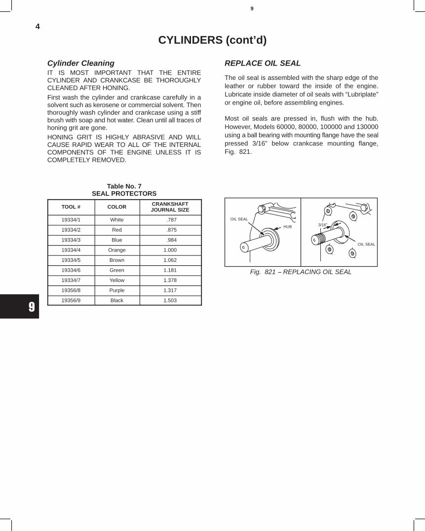
4
9
CYLINDERS (cont’d)
Cylinder CleaningIT IS MOST IMPORTANT THAT THE ENTIRECYLINDER AND CRANKCASE BE THOROUGHLYCLEANED AFTER HONING.
First wash the cylinder and crankcase carefully in asolvent such as kerosene or commercial solvent. Thenthoroughly wash cylinder and crankcase using a stiffbrush with soap and hot water. Clean until all traces ofhoning grit are gone.HONING GRIT IS HIGHLY ABRASIVE AND WILLCAUSE RAPID WEAR TO ALL OF THE INTERNALCOMPONENTS OF THE ENGINE UNLESS IT ISCOMPLETELY REMOVED.
Table No. 7SEAL PROTECTORS
TOOL # COLOR CRANKSHAFTJOURNAL SIZE
19334/1 White .787
19334/2 Red .875
19334/3 Blue .984
19334/4 Orange 1.000
19334/5 Brown 1.062
19334/6 Green 1.181
19334/7 Yellow 1.378
19356/8 Purple 1.317
19356/9 Black 1.503
REPLACE OIL SEAL
The oil seal is assembled with the sharp edge of theleather or rubber toward the inside of the engine.Lubricate inside diameter of oil seals with “Lubriplate”or engine oil, before assembling engines.
Most oil seals are pressed in, flush with the hub.However, Models 60000, 80000, 100000 and 130000using a ball bearing with mounting flange have the sealpressed 3/16” below crankcase mounting flange,Fig. 821.
OIL SEAL
3/16”
OIL SEAL
Fig. 821 − REPLACING OIL SEAL
HUB

1
10
Section 10BEARINGS
CAST IRON CYLINDERS (PLAIN BEARINGS)The main bearings consist of the magneto bearing andthe PTO bearing. The magneto bearing is a bushingpressed into the magneto plate and reamed to size.The PTO bearing may either be a bushing or a ballbearing and may be mounted either in the crankcaseor on a removable plate called the bearing support.The bushing type of bearing is very efficient but
extreme care must be taken to maintain the properclearance between the crankshaft journal and thebearing surface. Too little clearance will cut off the oilsupply and too much will cause excessive vibrationand wear. If both main bearings and crankshaftjournals are within proper limits, this clearance will bemaintained.
Table No. 9TOOLS FOR REAMING MAIN BEARINGS − CAST IRON CYLINDERS
MAGNETO BEARING PTO BEARING LINE
ENGINEMODEL
GAUGETO CHECKMAGNETOBEARING
DRIVERTO
REPLACEMAGNETOBEARING
GUIDEBUSHING
TO FITPTO
BEARING
REAMERTO FIT
MAGNETOBEARING
GAUGETO CHECK
PTOBEARING
DRIVERTO
REPLACEPTO
BEARING
GUIDEBUSHING
TO FITMAGNETOBEARING
REAMERTO FITPTO
BEARING
LINEREAMER
TO FITMAGNETO
& PTOBEARING
A 19093† 19152† 19088† 19083† 19091† 19120† 19082† 19089†
AP 19093† 19152† 19090† 19083† BB BB BB BB
B 19093† 19152† 19081† 19083† 19092† 19152† 19082† 19084†
BP 19093† 19152† 19086† 19083 BB BB BB BB
FH 19111† 69093-T1† 19148† 69093-T1† 19149†
FI 19111† 69093-T1† 19148† 69093-T1† 19149†
FJ 19111† 69093-T1† 19148† 69093-T1† 19149†
H 19093† 19152† 19088† 19083† 19091† 19120† 19082† 19089†
I *19098† 19124 19097 19095 19098† 19124 19094 19095
IBP 19098† 19124 19097 19095 BB BB BB BB
K 19093† 19152† 19081† 19093† 19092† 19152† 60115-T1-14†
19084†
L 19111† 69093-T1† 19148† 19124 19149†
M 19111† 69093-T1† 19148† 19124 19149†
N 19098† 19124 19094 19095 19098† 19124 19094 19095
NP 19098† 19124 19094 19095 BB BB BB BB
NS 19098† 19124 19094 19095 19098† 19124 19094 19095
P 19111† 69093-T1† 69265-T2† 19120† 69265-T1†
Q 19111† 69093-T1† 69265-T2† 19120† 69265-T1†
R 19111† 69093-T1† 19092† 29347-T1† 69054-T2†
S 19111† 69093-T1† 19148† 19124† 19149†
T 19111† 69093-T1† 19148† 19124 19149†
U 19098† 19124 19094 19095 19098† 19124 19094 19095
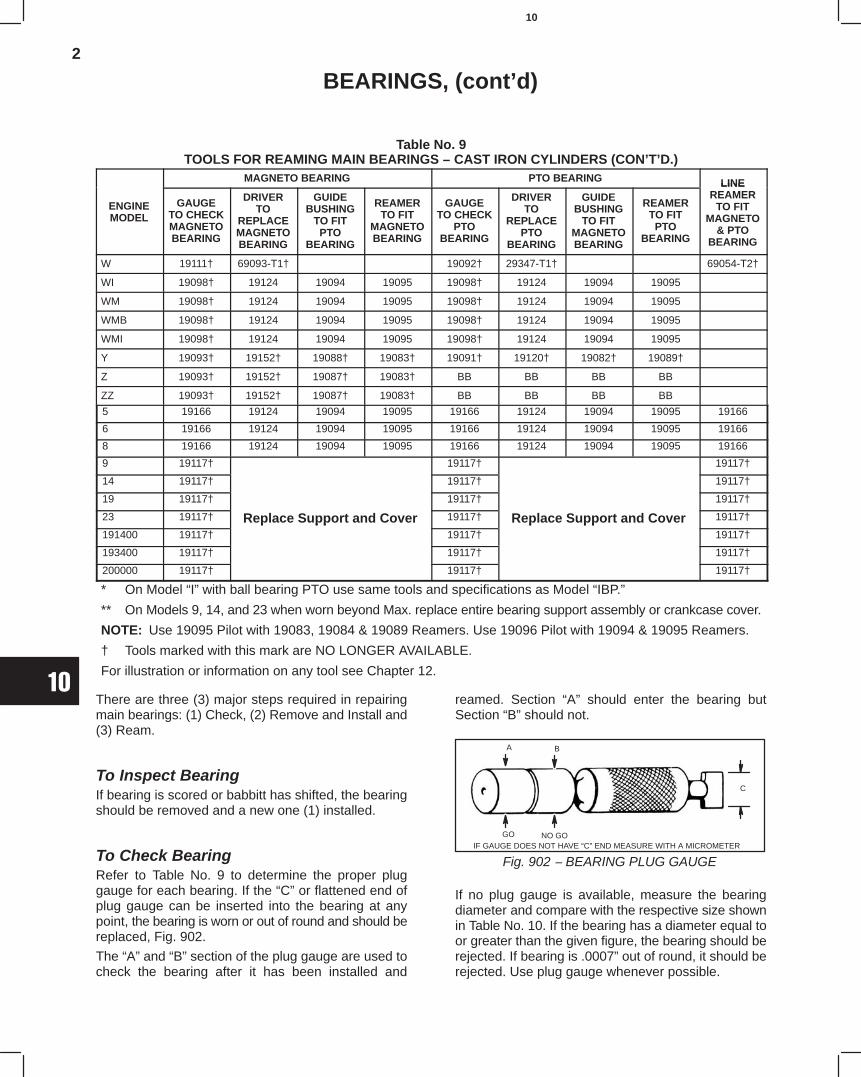
2
10
BEARINGS, (cont’d)
Table No. 9TOOLS FOR REAMING MAIN BEARINGS − CAST IRON CYLINDERS (CON’T’D.)
MAGNETO BEARING PTO BEARING LINE
ENGINEMODEL
GAUGETO CHECKMAGNETOBEARING
DRIVERTO
REPLACEMAGNETOBEARING
GUIDEBUSHING
TO FITPTO
BEARING
REAMERTO FIT
MAGNETOBEARING
GAUGETO CHECK
PTOBEARING
DRIVERTO
REPLACEPTO
BEARING
GUIDEBUSHING
TO FITMAGNETOBEARING
REAMERTO FITPTO
BEARING
LINEREAMER
TO FITMAGNETO
& PTOBEARING
W 19111† 69093-T1† 19092† 29347-T1† 69054-T2†
WI 19098† 19124 19094 19095 19098† 19124 19094 19095
WM 19098† 19124 19094 19095 19098† 19124 19094 19095
WMB 19098† 19124 19094 19095 19098† 19124 19094 19095
WMI 19098† 19124 19094 19095 19098† 19124 19094 19095
Y 19093† 19152† 19088† 19083† 19091† 19120† 19082† 19089†
Z 19093† 19152† 19087† 19083† BB BB BB BB
ZZ 19093† 19152† 19087† 19083† BB BB BB BB
5 19166 19124 19094 19095 19166 19124 19094 19095 19166
6 19166 19124 19094 19095 19166 19124 19094 19095 19166
8 19166 19124 19094 19095 19166 19124 19094 19095 19166
9 19117† 19117† 19117†
14 19117† 19117† 19117†
19 19117† 19117† 19117†
23 19117† Replace Support and Cover 19117† Replace Support and Cover 19117†
191400 19117†
p pp19117†
p pp19117†
193400 19117† 19117† 19117†
200000 19117† 19117† 19117†
* On Model “I” with ball bearing PTO use same tools and specifications as Model “IBP.”
** On Models 9, 14, and 23 when worn beyond Max. replace entire bearing support assembly or crankcase cover.
NOTE: Use 19095 Pilot with 19083, 19084 & 19089 Reamers. Use 19096 Pilot with 19094 & 19095 Reamers.
† Tools marked with this mark are NO LONGER AVAILABLE.
For illustration or information on any tool see Chapter 12.
There are three (3) major steps required in repairingmain bearings: (1) Check, (2) Remove and Install and(3) Ream.
To Inspect BearingIf bearing is scored or babbitt has shifted, the bearingshould be removed and a new one (1) installed.
To Check BearingRefer to Table No. 9 to determine the proper pluggauge for each bearing. If the “C” or flattened end ofplug gauge can be inserted into the bearing at anypoint, the bearing is worn or out of round and should bereplaced, Fig. 902.
The “A” and “B” section of the plug gauge are used tocheck the bearing after it has been installed and
reamed. Section “A” should enter the bearing butSection “B” should not.
Fig. 902 − BEARING PLUG GAUGE
A B
GO NO GO
C
IF GAUGE DOES NOT HAVE “C” END MEASURE WITH A MICROMETER
If no plug gauge is available, measure the bearingdiameter and compare with the respective size shownin Table No. 10. If the bearing has a diameter equal toor greater than the given figure, the bearing should berejected. If bearing is .0007” out of round, it should berejected. Use plug gauge whenever possible.
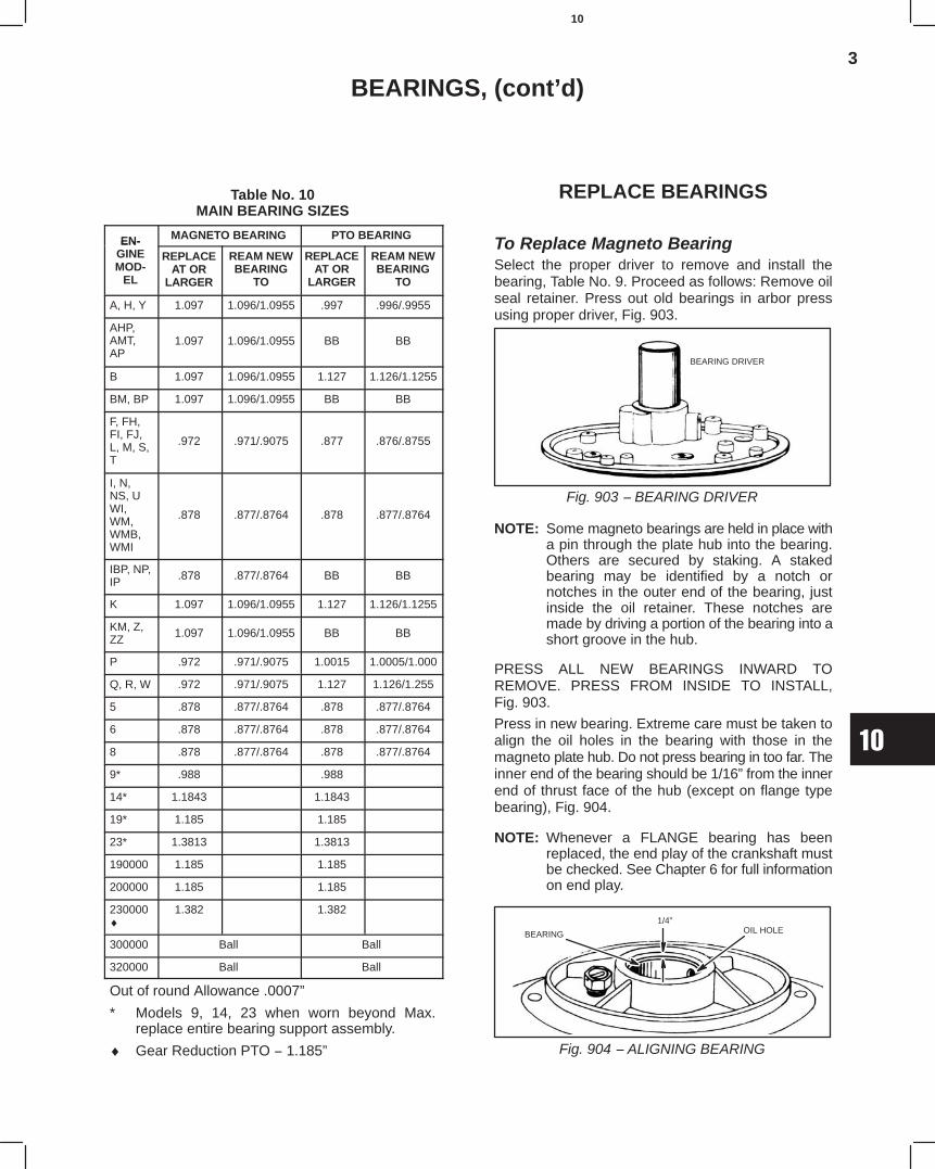
3
10
BEARINGS, (cont’d)
Table No. 10MAIN BEARING SIZES
EN- MAGNETO BEARING PTO BEARINGEN-GINEMOD-
EL
REPLACEAT OR
LARGER
REAM NEWBEARING
TO
REPLACEAT OR
LARGER
REAM NEWBEARING
TO
A, H, Y 1.097 1.096/1.0955 .997 .996/.9955
AHP,AMT,AP
1.097 1.096/1.0955 BB BB
B 1.097 1.096/1.0955 1.127 1.126/1.1255
BM, BP 1.097 1.096/1.0955 BB BB
F, FH,FI, FJ,L, M, S,T
.972 .971/.9075 .877 .876/.8755
I, N,NS, UWI,WM,WMB,WMI
.878 .877/.8764 .878 .877/.8764
IBP, NP,IP .878 .877/.8764 BB BB
K 1.097 1.096/1.0955 1.127 1.126/1.1255
KM, Z,ZZ 1.097 1.096/1.0955 BB BB
P .972 .971/.9075 1.0015 1.0005/1.000
Q, R, W .972 .971/.9075 1.127 1.126/1.255
5 .878 .877/.8764 .878 .877/.8764
6 .878 .877/.8764 .878 .877/.8764
8 .878 .877/.8764 .878 .877/.8764
9* .988 .988
14* 1.1843 1.1843
19* 1.185 1.185
23* 1.3813 1.3813
190000 1.185 1.185
200000 1.185 1.185
230000♦
1.382 1.382
300000 Ball Ball
320000 Ball Ball
Out of round Allowance .0007”
* Models 9, 14, 23 when worn beyond Max.replace entire bearing support assembly.
♦ Gear Reduction PTO − 1.185”
REPLACE BEARINGS
To Replace Magneto BearingSelect the proper driver to remove and install thebearing, Table No. 9. Proceed as follows: Remove oilseal retainer. Press out old bearings in arbor pressusing proper driver, Fig. 903.
Fig. 903 − BEARING DRIVER
BEARING DRIVER
NOTE: Some magneto bearings are held in place witha pin through the plate hub into the bearing.Others are secured by staking. A stakedbearing may be identified by a notch ornotches in the outer end of the bearing, justinside the oil retainer. These notches aremade by driving a portion of the bearing into ashort groove in the hub.
PRESS ALL NEW BEARINGS INWARD TOREMOVE. PRESS FROM INSIDE TO INSTALL,Fig. 903.
Press in new bearing. Extreme care must be taken toalign the oil holes in the bearing with those in themagneto plate hub. Do not press bearing in too far. Theinner end of the bearing should be 1/16” from the innerend of thrust face of the hub (except on flange typebearing), Fig. 904.
NOTE: Whenever a FLANGE bearing has beenreplaced, the end play of the crankshaft mustbe checked. See Chapter 6 for full informationon end play.
Fig. 904 − ALIGNING BEARING
BEARING
1/4”OIL HOLE
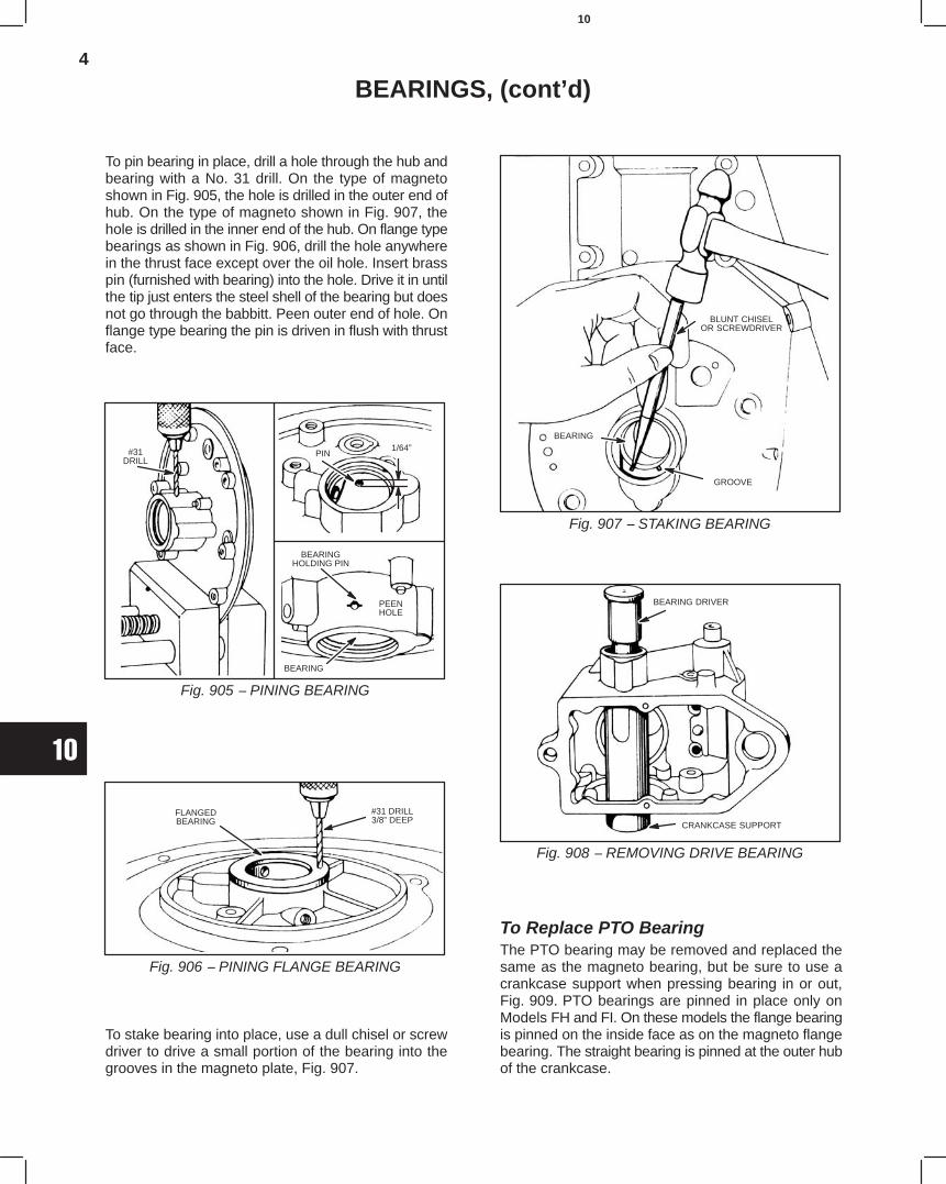
4
10
BEARINGS, (cont’d)
To pin bearing in place, drill a hole through the hub andbearing with a No. 31 drill. On the type of magnetoshown in Fig. 905, the hole is drilled in the outer end ofhub. On the type of magneto shown in Fig. 907, thehole is drilled in the inner end of the hub. On flange typebearings as shown in Fig. 906, drill the hole anywherein the thrust face except over the oil hole. Insert brasspin (furnished with bearing) into the hole. Drive it in untilthe tip just enters the steel shell of the bearing but doesnot go through the babbitt. Peen outer end of hole. Onflange type bearing the pin is driven in flush with thrustface.
Fig. 905 − PINING BEARING
#31DRILL
PIN1/64”
BEARINGHOLDING PIN
PEENHOLE
BEARING
Fig. 906 − PINING FLANGE BEARING
FLANGEDBEARING
#31 DRILL3/8” DEEP
To stake bearing into place, use a dull chisel or screwdriver to drive a small portion of the bearing into thegrooves in the magneto plate, Fig. 907.
Fig. 907 − STAKING BEARING
BLUNT CHISELOR SCREWDRIVER
GROOVE
BEARING
Fig. 908 − REMOVING DRIVE BEARING
BEARING DRIVER
CRANKCASE SUPPORT
To Replace PTO BearingThe PTO bearing may be removed and replaced thesame as the magneto bearing, but be sure to use acrankcase support when pressing bearing in or out,Fig. 909. PTO bearings are pinned in place only onModels FH and FI. On these models the flange bearingis pinned on the inside face as on the magneto flangebearing. The straight bearing is pinned at the outer hubof the crankcase.
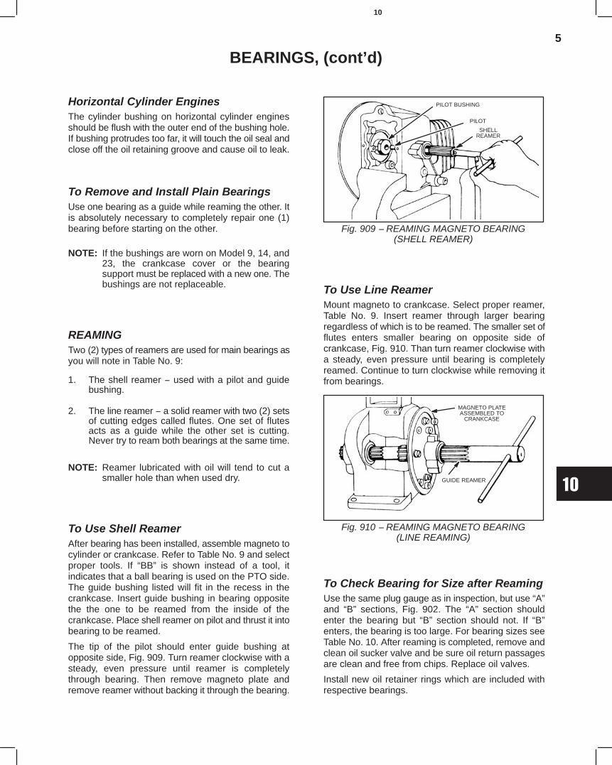
5
10
BEARINGS, (cont’d)
Horizontal Cylinder EnginesThe cylinder bushing on horizontal cylinder enginesshould be flush with the outer end of the bushing hole.If bushing protrudes too far, it will touch the oil seal andclose off the oil retaining groove and cause oil to leak.
To Remove and Install Plain BearingsUse one bearing as a guide while reaming the other. Itis absolutely necessary to completely repair one (1)bearing before starting on the other.
NOTE: If the bushings are worn on Model 9, 14, and23, the crankcase cover or the bearingsupport must be replaced with a new one. Thebushings are not replaceable.
REAMINGTwo (2) types of reamers are used for main bearings asyou will note in Table No. 9:
1. The shell reamer − used with a pilot and guidebushing.
2. The line reamer − a solid reamer with two (2) setsof cutting edges called flutes. One set of flutesacts as a guide while the other set is cutting.Never try to ream both bearings at the same time.
NOTE: Reamer lubricated with oil will tend to cut asmaller hole than when used dry.
To Use Shell ReamerAfter bearing has been installed, assemble magneto tocylinder or crankcase. Refer to Table No. 9 and selectproper tools. If “BB” is shown instead of a tool, itindicates that a ball bearing is used on the PTO side.The guide bushing listed will fit in the recess in thecrankcase. Insert guide bushing in bearing oppositethe the one to be reamed from the inside of thecrankcase. Place shell reamer on pilot and thrust it intobearing to be reamed.
The tip of the pilot should enter guide bushing atopposite side, Fig. 909. Turn reamer clockwise with asteady, even pressure until reamer is completelythrough bearing. Then remove magneto plate andremove reamer without backing it through the bearing.
Fig. 909 − REAMING MAGNETO BEARING(SHELL REAMER)
PILOT BUSHING
PILOT
SHELLREAMER
To Use Line ReamerMount magneto to crankcase. Select proper reamer,Table No. 9. Insert reamer through larger bearingregardless of which is to be reamed. The smaller set offlutes enters smaller bearing on opposite side ofcrankcase, Fig. 910. Than turn reamer clockwise witha steady, even pressure until bearing is completelyreamed. Continue to turn clockwise while removing itfrom bearings.
Fig. 910 − REAMING MAGNETO BEARING(LINE REAMING)
MAGNETO PLATEASSEMBLED TO
CRANKCASE
GUIDE REAMER
To Check Bearing for Size after ReamingUse the same plug gauge as in inspection, but use “A”and “B” sections, Fig. 902. The “A” section shouldenter the bearing but “B” section should not. If “B”enters, the bearing is too large. For bearing sizes seeTable No. 10. After reaming is completed, remove andclean oil sucker valve and be sure oil return passagesare clean and free from chips. Replace oil valves.
Install new oil retainer rings which are included withrespective bearings.
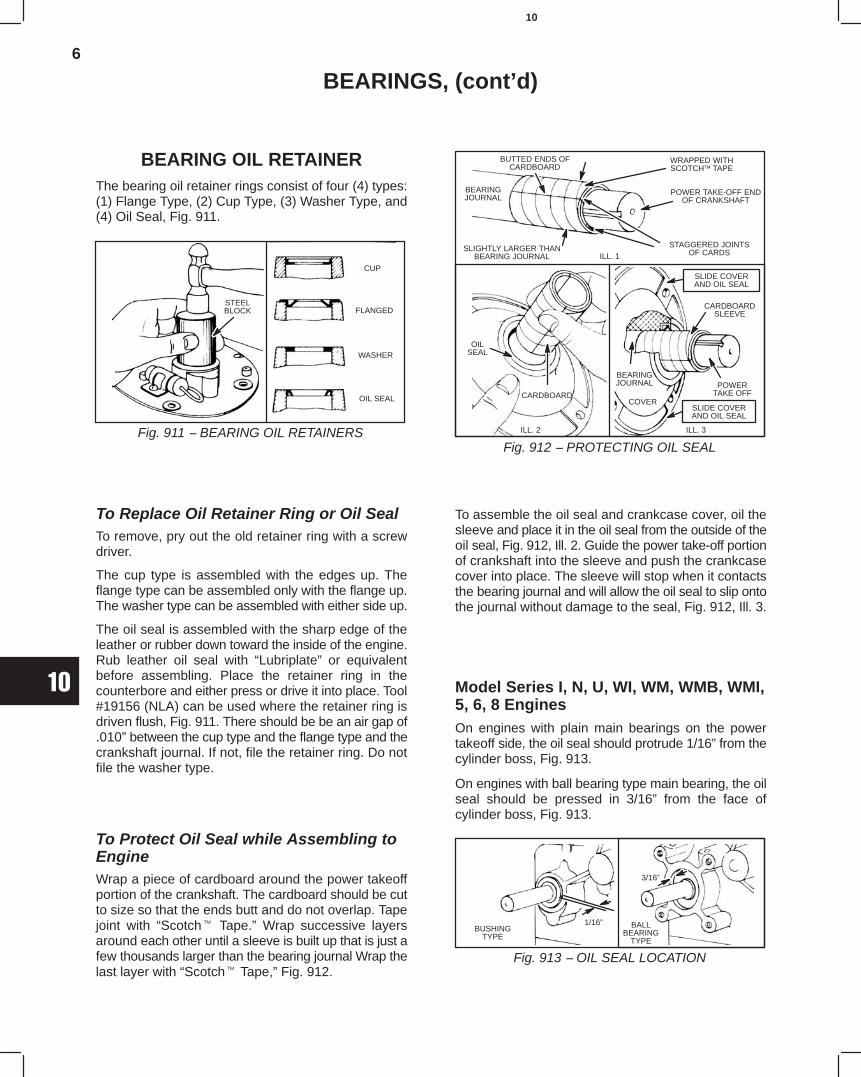
6
10
BEARINGS, (cont’d)
BEARING OIL RETAINERThe bearing oil retainer rings consist of four (4) types:(1) Flange Type, (2) Cup Type, (3) Washer Type, and(4) Oil Seal, Fig. 911.
Fig. 911 − BEARING OIL RETAINERS
STEELBLOCK
CUP
FLANGED
WASHER
OIL SEAL
To Replace Oil Retainer Ring or Oil SealTo remove, pry out the old retainer ring with a screwdriver.
The cup type is assembled with the edges up. Theflange type can be assembled only with the flange up.The washer type can be assembled with either side up.
The oil seal is assembled with the sharp edge of theleather or rubber down toward the inside of the engine.Rub leather oil seal with “Lubriplate” or equivalentbefore assembling. Place the retainer ring in thecounterbore and either press or drive it into place. Tool#19156 (NLA) can be used where the retainer ring isdriven flush, Fig. 911. There should be be an air gap of.010” between the cup type and the flange type and thecrankshaft journal. If not, file the retainer ring. Do notfile the washer type.
To Protect Oil Seal while Assembling toEngineWrap a piece of cardboard around the power takeoffportion of the crankshaft. The cardboard should be cutto size so that the ends butt and do not overlap. Tapejoint with “Scotch Tape.” Wrap successive layersaround each other until a sleeve is built up that is just afew thousands larger than the bearing journal Wrap thelast layer with “Scotch Tape,” Fig. 912.
Fig. 912 − PROTECTING OIL SEAL
BUTTED ENDS OFCARDBOARD
WRAPPED WITHSCOTCH TAPE
POWER TAKE-OFF ENDOF CRANKSHAFT
BEARINGJOURNAL
SLIGHTLY LARGER THANBEARING JOURNAL
STAGGERED JOINTSOF CARDSILL. 1
CARDBOARDSLEEVE
POWERTAKE OFF
ILL. 3
BEARINGJOURNAL
COVER
OILSEAL
CARDBOARD
ILL. 2
SLIDE COVERAND OIL SEAL
SLIDE COVERAND OIL SEAL
To assemble the oil seal and crankcase cover, oil thesleeve and place it in the oil seal from the outside of theoil seal, Fig. 912, Ill. 2. Guide the power take-off portionof crankshaft into the sleeve and push the crankcasecover into place. The sleeve will stop when it contactsthe bearing journal and will allow the oil seal to slip ontothe journal without damage to the seal, Fig. 912, Ill. 3.
Model Series I, N, U, WI, WM, WMB, WMI,5, 6, 8 EnginesOn engines with plain main bearings on the powertakeoff side, the oil seal should protrude 1/16” from thecylinder boss, Fig. 913.
On engines with ball bearing type main bearing, the oilseal should be pressed in 3/16” from the face ofcylinder boss, Fig. 913.
Fig. 913 − OIL SEAL LOCATION
BUSHINGTYPE
BALLBEARING
TYPE
1/16”
3/16”
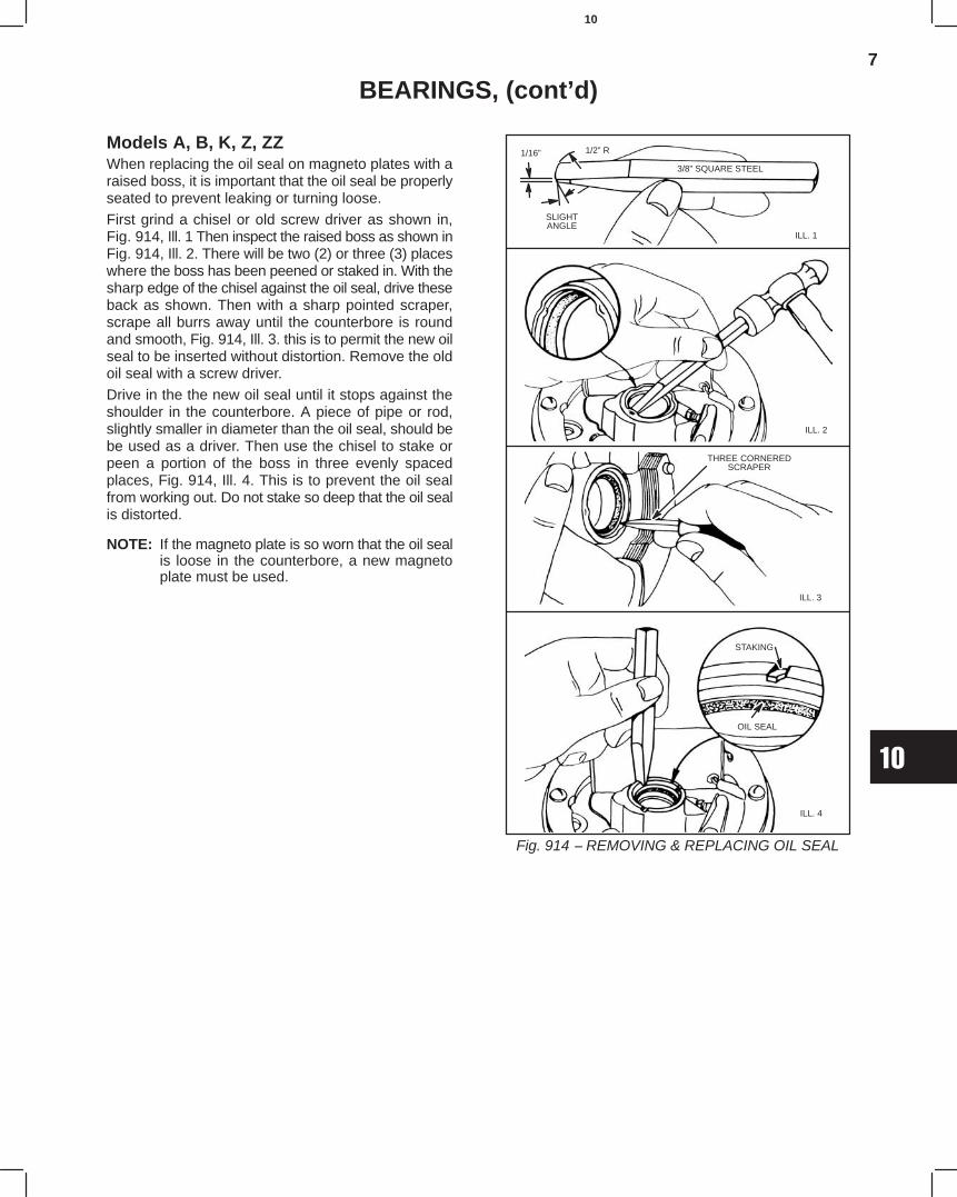
7
10
BEARINGS, (cont’d)
Models A, B, K, Z, ZZWhen replacing the oil seal on magneto plates with araised boss, it is important that the oil seal be properlyseated to prevent leaking or turning loose.
First grind a chisel or old screw driver as shown in,Fig. 914, Ill. 1 Then inspect the raised boss as shown inFig. 914, Ill. 2. There will be two (2) or three (3) placeswhere the boss has been peened or staked in. With thesharp edge of the chisel against the oil seal, drive theseback as shown. Then with a sharp pointed scraper,scrape all burrs away until the counterbore is roundand smooth, Fig. 914, Ill. 3. this is to permit the new oilseal to be inserted without distortion. Remove the oldoil seal with a screw driver.
Drive in the the new oil seal until it stops against theshoulder in the counterbore. A piece of pipe or rod,slightly smaller in diameter than the oil seal, should bebe used as a driver. Then use the chisel to stake orpeen a portion of the boss in three evenly spacedplaces, Fig. 914, Ill. 4. This is to prevent the oil sealfrom working out. Do not stake so deep that the oil sealis distorted.
NOTE: If the magneto plate is so worn that the oil sealis loose in the counterbore, a new magnetoplate must be used.
Fig. 914 − REMOVING & REPLACING OIL SEAL
3/8” SQUARE STEEL
ILL. 1
SLIGHTANGLE
1/2” R1/16”
ILL. 2
THREE CORNEREDSCRAPER
ILL. 3
STAKING
OIL SEAL
ILL. 4
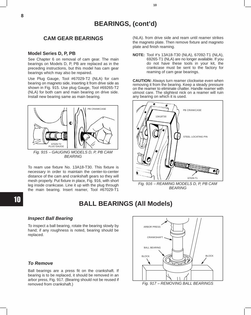
8
10
BEARINGS, (cont’d)
CAM GEAR BEARINGS
Model Series D, P, PBSee Chapter 6 on removal of cam gear. The mainbearings on Models D, P, PB are replaced as in thepreceding instructions, but this model has cam gearbearings which may also be repaired.
Use Plug Gauge, Tool #67029-T2 (NLA) for cambearing on magneto side, inserting it from drive side asshown in Fig. 915. Use plug Gauge, Tool #69265-T2(NLA) for both cam and main bearing on drive side.Install new bearing same as main bearing.
Fig. 915 − GAUGING MODELS D, P, PB CAMBEARING
PB CRANKCASE
67029-T2PLUG GAUGE
To ream use fixture No. 13A18-T30. This fixture isnecessary in order to maintain the center-to-centerdistance of the cam and crankshaft gears so they willmesh properly. Put fixture in place, Fig. 916, with shortleg inside crankcase. Line it up with the plug throughthe main bearing. Insert reamer, Tool #67029-T1
(NLA). from drive side and ream until reamer strikesthe magneto plate. Then remove fixture and magnetoplate and finish reaming.
NOTE: Tool #’s 13A18-T30 (NLA), 67092-T1 (NLA),69265-T1 (NLA) are no longer available. If youdo not have these tools in your kit, thecrankcase must be sent to the factory forreaming of cam gear bearings.
CAUTION: Always turn reamer clockwise even whenremoving it from the bearing. Keep a steady pressureon the reamer to eliminate chatter. Handle reamer withutmost care. The slightest nick on a reamer will ruinany bearing on which it is used.
Fig. 916 − REAMING MODELS D, P, PB CAMBEARING
PB CRANKCASE
STEEL LOCATING PIN
67029-T1
13A18T30
BALL BEARINGS (All Models)
Inspect Ball Bearing
To inspect a ball bearing, rotate the bearing slowly byhand; if any roughness is noted, bearing should bereplaced.
To Remove
Ball bearings are a press fit on the crankshaft. Ifbearing is to be replaced, it should be removed in anarbor press, Fig. 917. (Bearing should not be reused ifremoved from crankshaft.)
ARBOR PRESS
CRANKSHAFT
BALL BEARING
BLOCKBLOCK
Fig. 917 − REMOVING BALL BEARINGS
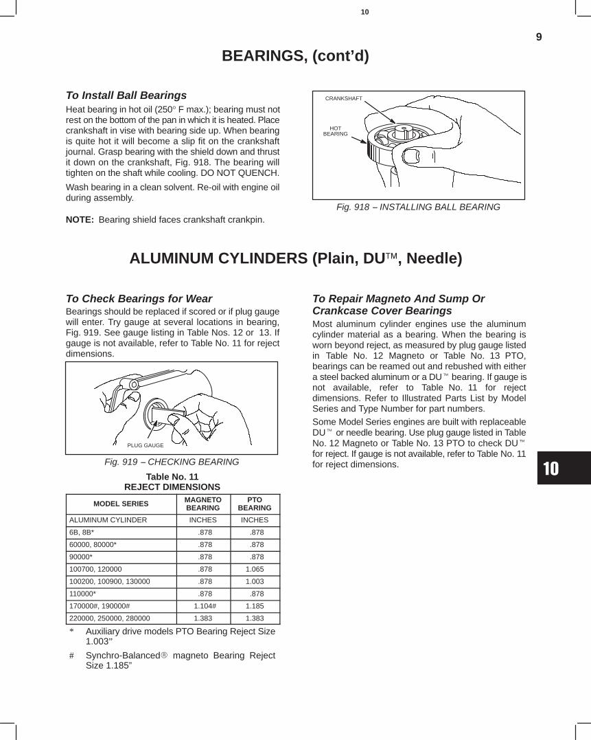
9
10
BEARINGS, (cont’d)
To Install Ball BearingsHeat bearing in hot oil (250° F max.); bearing must notrest on the bottom of the pan in which it is heated. Placecrankshaft in vise with bearing side up. When bearingis quite hot it will become a slip fit on the crankshaftjournal. Grasp bearing with the shield down and thrustit down on the crankshaft, Fig. 918. The bearing willtighten on the shaft while cooling. DO NOT QUENCH.
Wash bearing in a clean solvent. Re-oil with engine oilduring assembly.
NOTE: Bearing shield faces crankshaft crankpin.Fig. 918 − INSTALLING BALL BEARING
HOTBEARING
CRANKSHAFT
ALUMINUM CYLINDERS (Plain, DU, Needle)
To Check Bearings for WearBearings should be replaced if scored or if plug gaugewill enter. Try gauge at several locations in bearing,Fig. 919. See gauge listing in Table Nos. 12 or 13. Ifgauge is not available, refer to Table No. 11 for rejectdimensions.
PLUG GAUGE
Fig. 919 − CHECKING BEARING
Table No. 11REJECT DIMENSIONS
MODEL SERIES MAGNETOBEARING
PTOBEARING
ALUMINUM CYLINDER INCHES INCHES
6B, 8B* .878 .878
60000, 80000* .878 .878
90000* .878 .878
100700, 120000 .878 1.065
100200, 100900, 130000 .878 1.003
110000* .878 .878
170000#, 190000# 1.104# 1.185
220000, 250000, 280000 1.383 1.383
* Auxiliary drive models PTO Bearing Reject Size1.003”
# Synchro-Balanced magneto Bearing RejectSize 1.185”
To Repair Magneto And Sump OrCrankcase Cover BearingsMost aluminum cylinder engines use the aluminumcylinder material as a bearing. When the bearing isworn beyond reject, as measured by plug gauge listedin Table No. 12 Magneto or Table No. 13 PTO,bearings can be reamed out and rebushed with eithera steel backed aluminum or a DU bearing. If gauge isnot available, refer to Table No. 11 for rejectdimensions. Refer to Illustrated Parts List by ModelSeries and Type Number for part numbers.
Some Model Series engines are built with replaceableDU or needle bearing. Use plug gauge listed in TableNo. 12 Magneto or Table No. 13 PTO to check DU
for reject. If gauge is not available, refer to Table No. 11for reject dimensions.
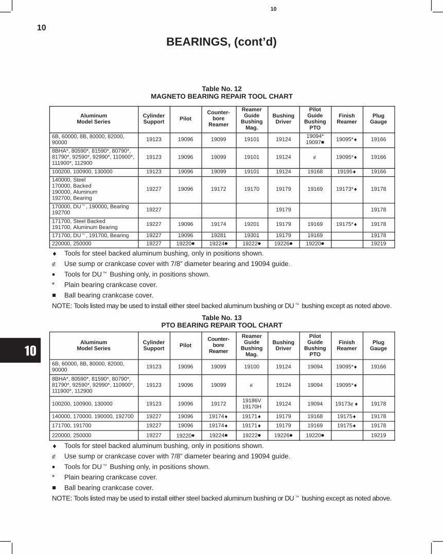
10
10
BEARINGS, (cont’d)
Table No. 12MAGNETO BEARING REPAIR TOOL CHART
AluminumModel Series
CylinderSupport Pilot
Counter-bore
Reamer
ReamerGuide
BushingMag.
BushingDriver
PilotGuide
BushingPTO
FinishReamer
PlugGauge
6B, 60000, 8B, 80000, 82000,90000 19123 19096 19099 19101 19124
19094*19097 19095*♦ 19166
8BHA*, 80590*, 81590*, 80790*,81790*, 92590*, 92990*, 110900*,111900*, 112900
19123 19096 19099 19101 19124 ∉ 19095*♦ 19166
100200, 100900, 130000 19123 19096 19099 19101 19124 19168 19195♦ 19166
140000, Steel170000, Backed190000, Aluminum192700, Bearing
19227 19096 19172 19170 19179 19169 19173*♦ 19178
170000, DU, 190000, Bearing192700 19227 19179 19178
171700, Steel Backed191700, Aluminum Bearing 19227 19096 19174 19201 19179 19169 19175*♦ 19178
171700, DU, 191700, Bearing 19227 19096 19281 19301 19179 19169 19178
220000, 250000 19227 19220 19224 19222 19226 19220 19219
♦ Tools for steel backed aluminum bushing, only in positions shown.
∉ Use sump or crankcase cover with 7/8” diameter bearing and 19094 guide.
• Tools for DU Bushing only, in positions shown.
* Plain bearing crankcase cover.
Ball bearing crankcase cover.
NOTE: Tools listed may be used to install either steel backed aluminum bushing or DU bushing except as noted above.
Table No. 13PTO BEARING REPAIR TOOL CHART
AluminumModel Series
CylinderSupport Pilot
Counter-bore
Reamer
ReamerGuide
BushingMag.
BushingDriver
PilotGuide
BushingPTO
FinishReamer
PlugGauge
6B, 60000, 8B, 80000, 82000,90000 19123 19096 19099 19100 19124 19094 19095*♦ 19166
8BHA*, 80590*, 81590*, 80790*,81790*, 92590*, 92990*, 110900*,111900*, 112900
19123 19096 19099 ∉ 19124 19094 19095*♦
100200, 100900, 130000 19123 19096 1917219186V19170H 19124 19094 19173∉♦ 19178
140000, 170000, 190000, 192700 19227 19096 19174♦ 19171♦ 19179 19168 19175♦ 19178
171700, 191700 19227 19096 19174♦ 19171♦ 19179 19169 19175♦ 19178
220000, 250000 19227 19220• 19224 19222 19226 19220 19219
♦ Tools for steel backed aluminum bushing, only in positions shown.
∉ Use sump or crankcase cover with 7/8” diameter bearing and 19094 guide.
• Tools for DU Bushing only, in positions shown.
* Plain bearing crankcase cover.
Ball bearing crankcase cover.
NOTE: Tools listed may be used to install either steel backed aluminum bushing or DU bushing except as noted above.
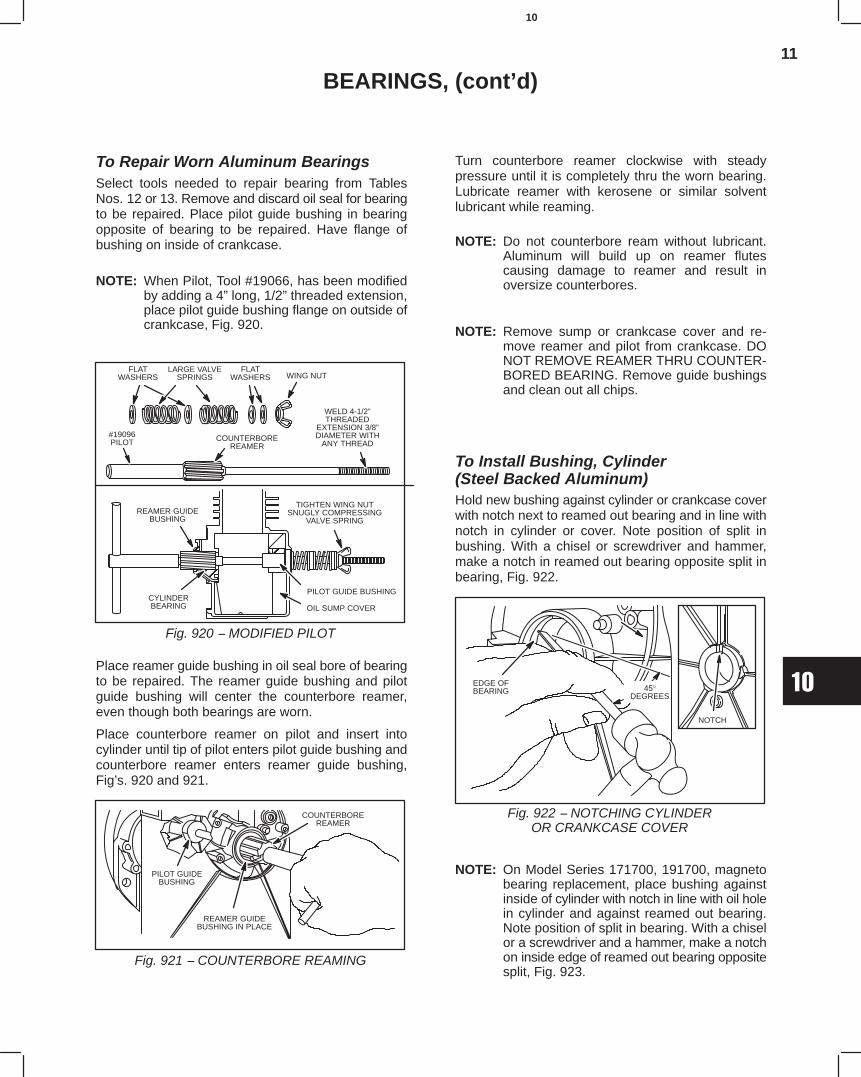
11
10
BEARINGS, (cont’d)
To Repair Worn Aluminum BearingsSelect tools needed to repair bearing from TablesNos. 12 or 13. Remove and discard oil seal for bearingto be repaired. Place pilot guide bushing in bearingopposite of bearing to be repaired. Have flange ofbushing on inside of crankcase.
NOTE: When Pilot, Tool #19066, has been modifiedby adding a 4” long, 1/2” threaded extension,place pilot guide bushing flange on outside ofcrankcase, Fig. 920.
ÉÉÉÉ
É ÉÉ
FLATWASHERS
#19096PILOT
LARGE VALVESPRINGS
COUNTERBOREREAMER
WELD 4-1/2”THREADED
EXTENSION 3/8”DIAMETER WITH
ANY THREAD
REAMER GUIDEBUSHING
CYLINDERBEARING
PILOT GUIDE BUSHING
OIL SUMP COVER
FLATWASHERS WING NUT
TIGHTEN WING NUTSNUGLY COMPRESSING
VALVE SPRING
Fig. 920 − MODIFIED PILOT
Place reamer guide bushing in oil seal bore of bearingto be repaired. The reamer guide bushing and pilotguide bushing will center the counterbore reamer,even though both bearings are worn.
Place counterbore reamer on pilot and insert intocylinder until tip of pilot enters pilot guide bushing andcounterbore reamer enters reamer guide bushing,Fig’s. 920 and 921.
PILOT GUIDEBUSHING
REAMER GUIDEBUSHING IN PLACE
COUNTERBOREREAMER
Fig. 921 − COUNTERBORE REAMING
Turn counterbore reamer clockwise with steadypressure until it is completely thru the worn bearing.Lubricate reamer with kerosene or similar solventlubricant while reaming.
NOTE: Do not counterbore ream without lubricant.Aluminum will build up on reamer flutescausing damage to reamer and result inoversize counterbores.
NOTE: Remove sump or crankcase cover and re-move reamer and pilot from crankcase. DONOT REMOVE REAMER THRU COUNTER-BORED BEARING. Remove guide bushingsand clean out all chips.
To Install Bushing, Cylinder (Steel Backed Aluminum)Hold new bushing against cylinder or crankcase coverwith notch next to reamed out bearing and in line withnotch in cylinder or cover. Note position of split inbushing. With a chisel or screwdriver and hammer,make a notch in reamed out bearing opposite split inbearing, Fig. 922.
EDGE OFBEARING 45°
DEGREES
NOTCH
Fig. 922 − NOTCHING CYLINDEROR CRANKCASE COVER
NOTE: On Model Series 171700, 191700, magnetobearing replacement, place bushing againstinside of cylinder with notch in line with oil holein cylinder and against reamed out bearing.Note position of split in bearing. With a chiselor a screwdriver and a hammer, make a notchon inside edge of reamed out bearing oppositesplit, Fig. 923.
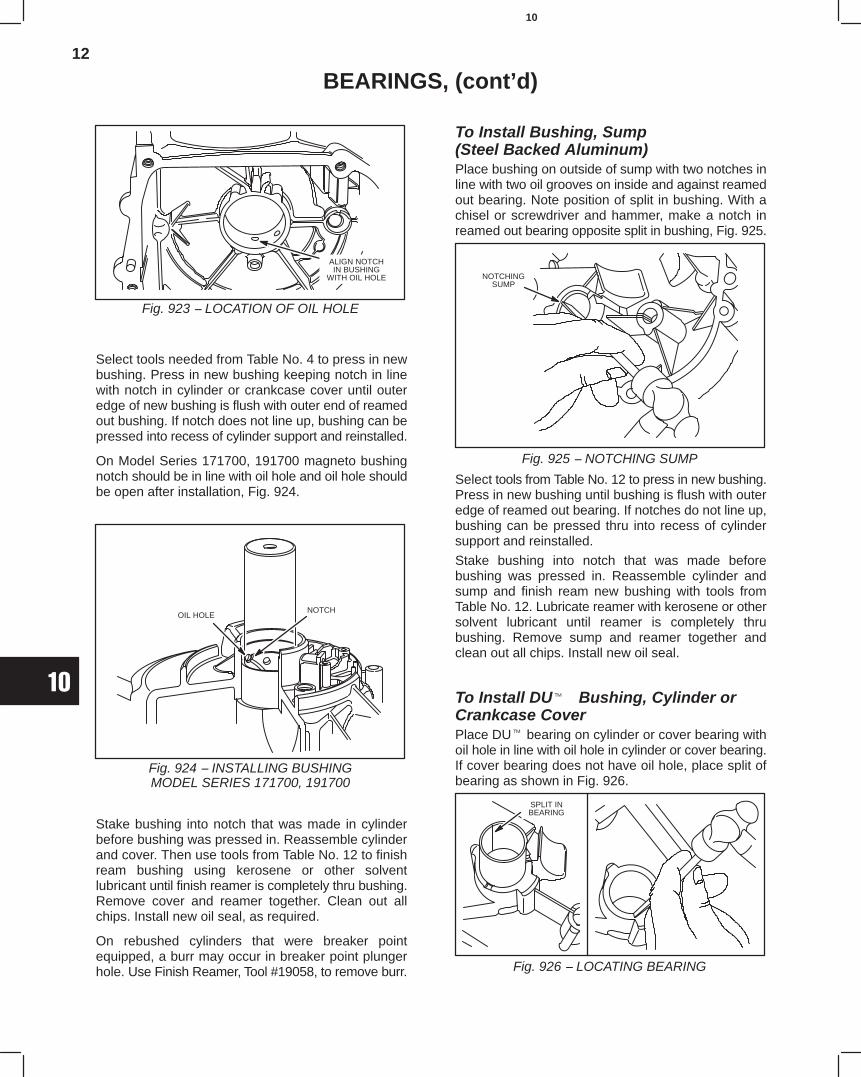
12
10
BEARINGS, (cont’d)
ALIGN NOTCHIN BUSHING
WITH OIL HOLE
Fig. 923 − LOCATION OF OIL HOLE
Select tools needed from Table No. 4 to press in newbushing. Press in new bushing keeping notch in linewith notch in cylinder or crankcase cover until outeredge of new bushing is flush with outer end of reamedout bushing. If notch does not line up, bushing can bepressed into recess of cylinder support and reinstalled.
On Model Series 171700, 191700 magneto bushingnotch should be in line with oil hole and oil hole shouldbe open after installation, Fig. 924.
OIL HOLENOTCH
Fig. 924 − INSTALLING BUSHINGMODEL SERIES 171700, 191700
Stake bushing into notch that was made in cylinderbefore bushing was pressed in. Reassemble cylinderand cover. Then use tools from Table No. 12 to finishream bushing using kerosene or other solventlubricant until finish reamer is completely thru bushing.Remove cover and reamer together. Clean out allchips. Install new oil seal, as required.
On rebushed cylinders that were breaker pointequipped, a burr may occur in breaker point plungerhole. Use Finish Reamer, Tool #19058, to remove burr.
To Install Bushing, Sump(Steel Backed Aluminum)Place bushing on outside of sump with two notches inline with two oil grooves on inside and against reamedout bearing. Note position of split in bushing. With achisel or screwdriver and hammer, make a notch inreamed out bearing opposite split in bushing, Fig. 925.
NOTCHINGSUMP
Fig. 925 − NOTCHING SUMP
Select tools from Table No. 12 to press in new bushing.Press in new bushing until bushing is flush with outeredge of reamed out bearing. If notches do not line up,bushing can be pressed thru into recess of cylindersupport and reinstalled.
Stake bushing into notch that was made beforebushing was pressed in. Reassemble cylinder andsump and finish ream new bushing with tools fromTable No. 12. Lubricate reamer with kerosene or othersolvent lubricant until reamer is completely thrubushing. Remove sump and reamer together andclean out all chips. Install new oil seal.
To Install DU Bushing, Cylinder orCrankcase CoverPlace DU bearing on cylinder or cover bearing withoil hole in line with oil hole in cylinder or cover bearing.If cover bearing does not have oil hole, place split ofbearing as shown in Fig. 926.
SPLIT INBEARING
Fig. 926 − LOCATING BEARING
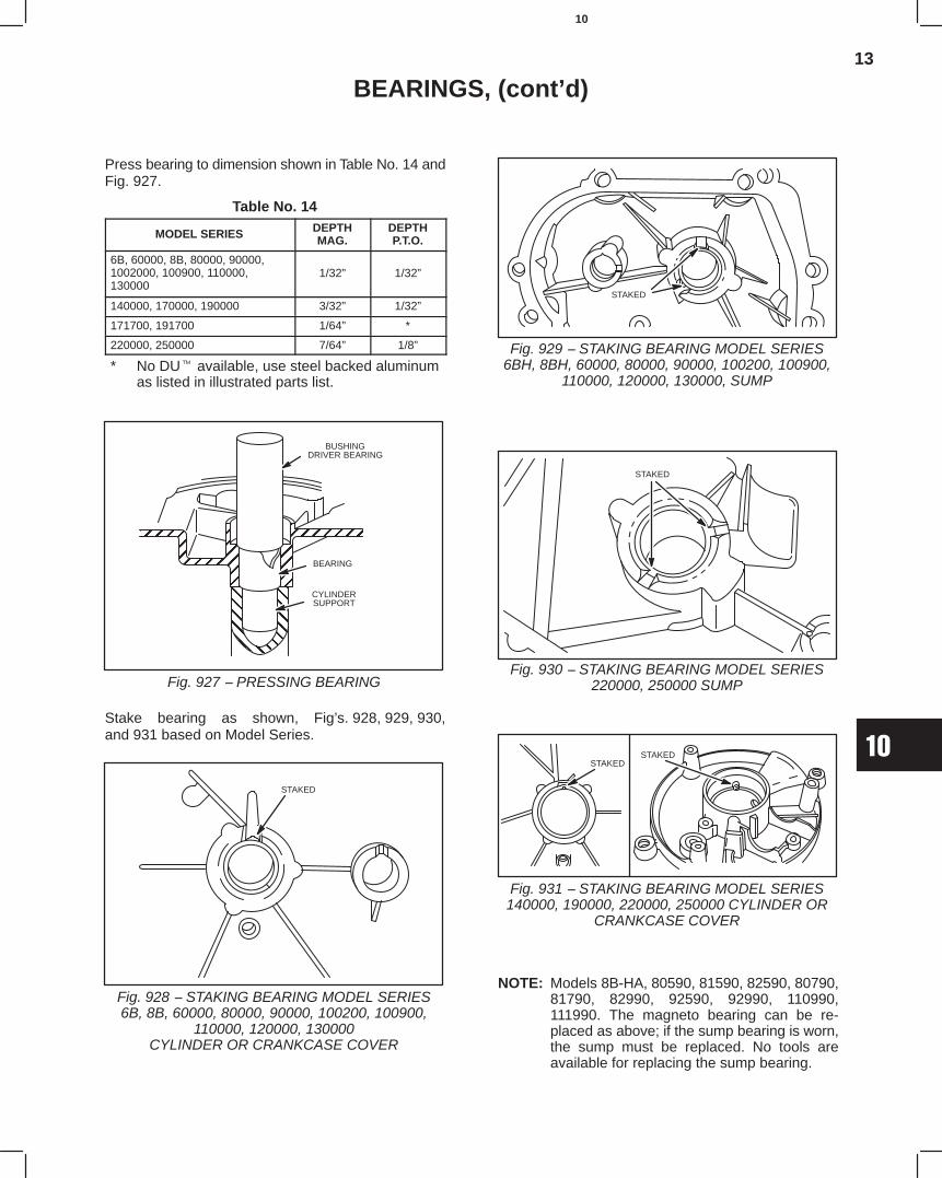
13
10
BEARINGS, (cont’d)
Press bearing to dimension shown in Table No. 14 andFig. 927.
Table No. 14
MODEL SERIES DEPTHMAG.
DEPTHP.T.O.
6B, 60000, 8B, 80000, 90000,1002000, 100900, 110000,130000
1/32” 1/32”
140000, 170000, 190000 3/32” 1/32”
171700, 191700 1/64” *
220000, 250000 7/64” 1/8”
* No DU available, use steel backed aluminumas listed in illustrated parts list.
ÇÇÇÇÇÇÇÇÇÇÇÇ
ÉÉÉÉÉÉÉÉÉÉÉÉÉÉÉÉÉÉÉÉ
ÉÉÉÉÉÉÉÉÉÉÉÉÉÉÉÉÉÉÉÉ
BUSHINGDRIVER BEARING
BEARING
CYLINDERSUPPORT
Fig. 927 − PRESSING BEARING
Stake bearing as shown, Fig’s. 928, 929, 930,and 931 based on Model Series.
STAKED
Fig. 928 − STAKING BEARING MODEL SERIES6B, 8B, 60000, 80000, 90000, 100200, 100900,
110000, 120000, 130000CYLINDER OR CRANKCASE COVER
STAKED
Fig. 929 − STAKING BEARING MODEL SERIES6BH, 8BH, 60000, 80000, 90000, 100200, 100900,
110000, 120000, 130000, SUMP
STAKED
Fig. 930 − STAKING BEARING MODEL SERIES220000, 250000 SUMP
STAKEDSTAKED
Fig. 931 − STAKING BEARING MODEL SERIES140000, 190000, 220000, 250000 CYLINDER OR
CRANKCASE COVER
NOTE: Models 8B-HA, 80590, 81590, 82590, 80790,81790, 82990, 92590, 92990, 110990,111990. The magneto bearing can be re-placed as above; if the sump bearing is worn,the sump must be replaced. No tools areavailable for replacing the sump bearing.
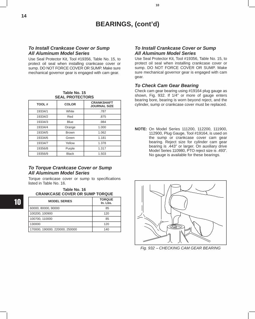
14
10
BEARINGS, (cont’d)
To Install Crankcase Cover or SumpAll Aluminum Model SeriesUse Seal Protector Kit, Tool #19356, Table No. 15, toprotect oil seal when installing crankcase cover orsump. DO NOT FORCE COVER OR SUMP. Make suremechanical governor gear is engaged with cam gear.
Table No. 15SEAL PROTECTORS
TOOL # COLOR CRANKSHAFTJOURNAL SIZE
19334/1 White .787
19334/2 Red .875
19334/3 Blue .984
19334/4 Orange 1.000
19334/5 Brown 1.062
19334/6 Green 1.181
19334/7 Yellow 1.378
19356/8 Purple 1.317
19356/9 Black 1.503
To Torque Crankcase Cover or SumpAll Aluminum Model SeriesTorque crankcase cover or sump to specificationslisted in Table No. 16.
Table No. 16CRANKCASE COVER OR SUMP TORQUE
MODEL SERIES TORQUEIn. Lbs.
60000, 80000, 90000 85
100200, 100900 120
100700, 110000 85
130000 120
170000, 190000, 220000, 250000 140
To Install Crankcase Cover or SumpAll Aluminum Model SeriesUse Seal Protector Kit, Tool #19356, Table No. 15, toprotect oil seal when installing crankcase cover orsump. DO NOT FORCE COVER OR SUMP. Makesure mechanical governor gear is engaged with camgear.
To Check Cam Gear BearingCheck cam gear bearing using #19164 plug gauge asshown, Fig. 932. If 1/4” or more of gauge entersbearing bore, bearing is worn beyond reject, and thecylinder, sump or crankcase cover must be replaced.
NOTE: On Model Series 111200, 112200, 111900,112900, Plug Gauge, Tool #19164, is used onthe sump or crankcase cover cam gearbearing. Reject size for cylinder cam gearbearing is .443” or larger. On auxiliary driveModel Series 110980, PTO reject size is .493”.No gauge is available for these bearings.
Fig. 932 − CHECKING CAM GEAR BEARING
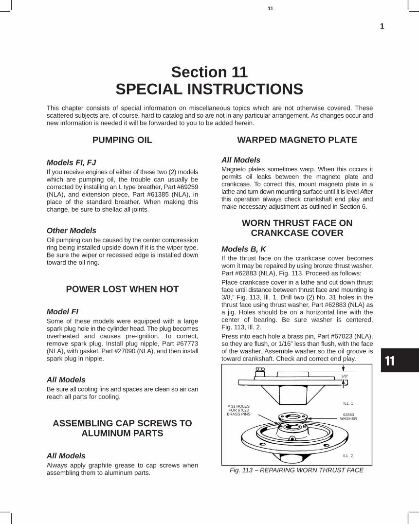
1
11
Section 11SPECIAL INSTRUCTIONS
This chapter consists of special information on miscellaneous topics which are not otherwise covered. Thesescattered subjects are, of course, hard to catalog and so are not in any particular arrangement. As changes occur andnew information is needed it will be forwarded to you to be added herein.
PUMPING OIL
Models FI, FJIf you receive engines of either of these two (2) modelswhich are pumping oil, the trouble can usually becorrected by installing an L type breather, Part #69259(NLA), and extension piece, Part #61385 (NLA), inplace of the standard breather. When making thischange, be sure to shellac all joints.
Other ModelsOil pumping can be caused by the center compressionring being installed upside down if it is the wiper type.Be sure the wiper or recessed edge is installed downtoward the oil ring.
POWER LOST WHEN HOT
Model FISome of these models were equipped with a largespark plug hole in the cylinder head. The plug becomesoverheated and causes pre-ignition. To correct,remove spark plug. Install plug nipple, Part #67773(NLA), with gasket, Part #27090 (NLA), and then installspark plug in nipple.
All ModelsBe sure all cooling fins and spaces are clean so air canreach all parts for cooling.
ASSEMBLING CAP SCREWS TOALUMINUM PARTS
All ModelsAlways apply graphite grease to cap screws whenassembling them to aluminum parts.
WARPED MAGNETO PLATE
All ModelsMagneto plates sometimes warp. When this occurs itpermits oil leaks between the magneto plate andcrankcase. To correct this, mount magneto plate in alathe and turn down mounting surface until it is level Afterthis operation always check crankshaft end play andmake necessary adjustment as outlined in Section 6.
WORN THRUST FACE ONCRANKCASE COVER
Models B, KIf the thrust face on the crankcase cover becomesworn it may be repaired by using bronze thrust washer,Part #62883 (NLA), Fig. 113. Proceed as follows:Place crankcase cover in a lathe and cut down thrustface until distance between thrust face and mounting is3/8,” Fig. 113, Ill. 1. Drill two (2) No. 31 holes in thethrust face using thrust washer, Part #62883 (NLA) asa jig. Holes should be on a horizontal line with thecenter of bearing. Be sure washer is centered,Fig. 113, Ill. 2.Press into each hole a brass pin, Part #67023 (NLA),so they are flush, or 1/16” less than flush, with the faceof the washer. Assemble washer so the oil groove istoward crankshaft. Check and correct end play.
Fig. 113 − REPAIRING WORN THRUST FACE
# 31 HOLESFOR 67023
BRASS PINS
ILL. 1
3/8”
62883WASHER
ILL. 2
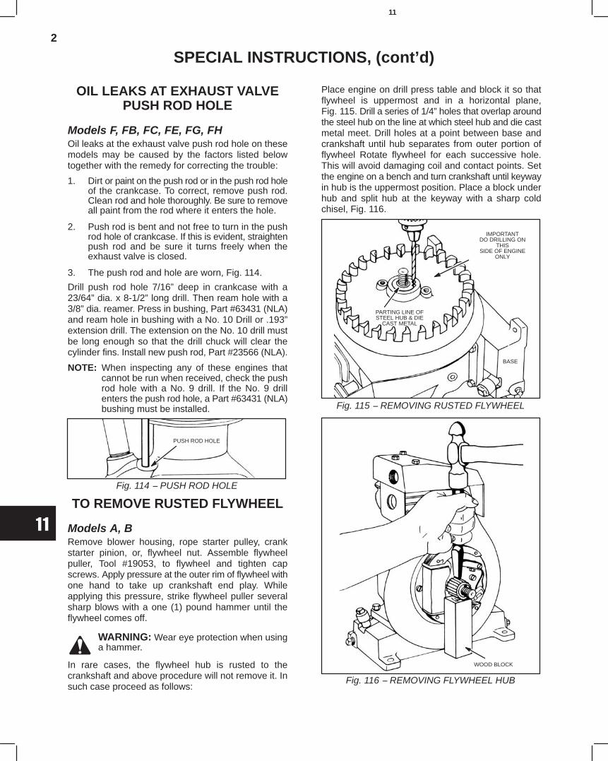
2
11
SPECIAL INSTRUCTIONS, (cont’d)
OIL LEAKS AT EXHAUST VALVEPUSH ROD HOLE
Models F, FB, FC, FE, FG, FHOil leaks at the exhaust valve push rod hole on thesemodels may be caused by the factors listed belowtogether with the remedy for correcting the trouble:
1. Dirt or paint on the push rod or in the push rod holeof the crankcase. To correct, remove push rod.Clean rod and hole thoroughly. Be sure to removeall paint from the rod where it enters the hole.
2. Push rod is bent and not free to turn in the pushrod hole of crankcase. If this is evident, straightenpush rod and be sure it turns freely when theexhaust valve is closed.
3. The push rod and hole are worn, Fig. 114.
Drill push rod hole 7/16” deep in crankcase with a23/64” dia. x 8-1/2” long drill. Then ream hole with a3/8” dia. reamer. Press in bushing, Part #63431 (NLA)and ream hole in bushing with a No. 10 Drill or .193”extension drill. The extension on the No. 10 drill mustbe long enough so that the drill chuck will clear thecylinder fins. Install new push rod, Part #23566 (NLA).
NOTE: When inspecting any of these engines thatcannot be run when received, check the pushrod hole with a No. 9 drill. If the No. 9 drillenters the push rod hole, a Part #63431 (NLA)bushing must be installed.
Fig. 114 − PUSH ROD HOLE
PUSH ROD HOLE
TO REMOVE RUSTED FLYWHEEL
Models A, BRemove blower housing, rope starter pulley, crankstarter pinion, or, flywheel nut. Assemble flywheelpuller, Tool #19053, to flywheel and tighten capscrews. Apply pressure at the outer rim of flywheel withone hand to take up crankshaft end play. Whileapplying this pressure, strike flywheel puller severalsharp blows with a one (1) pound hammer until theflywheel comes off.
WARNING: Wear eye protection when usinga hammer.
In rare cases, the flywheel hub is rusted to thecrankshaft and above procedure will not remove it. Insuch case proceed as follows:
Place engine on drill press table and block it so thatflywheel is uppermost and in a horizontal plane,Fig. 115. Drill a series of 1/4” holes that overlap aroundthe steel hub on the line at which steel hub and die castmetal meet. Drill holes at a point between base andcrankshaft until hub separates from outer portion offlywheel Rotate flywheel for each successive hole.This will avoid damaging coil and contact points. Setthe engine on a bench and turn crankshaft until keywayin hub is the uppermost position. Place a block underhub and split hub at the keyway with a sharp coldchisel, Fig. 116.
Fig. 115 − REMOVING RUSTED FLYWHEEL
PARTING LINE OFSTEEL HUB & DIE
CAST METAL
BASE
IMPORTANTDO DRILLING ON
THISSIDE OF ENGINE
ONLY
Fig. 116 − REMOVING FLYWHEEL HUB
WOOD BLOCK
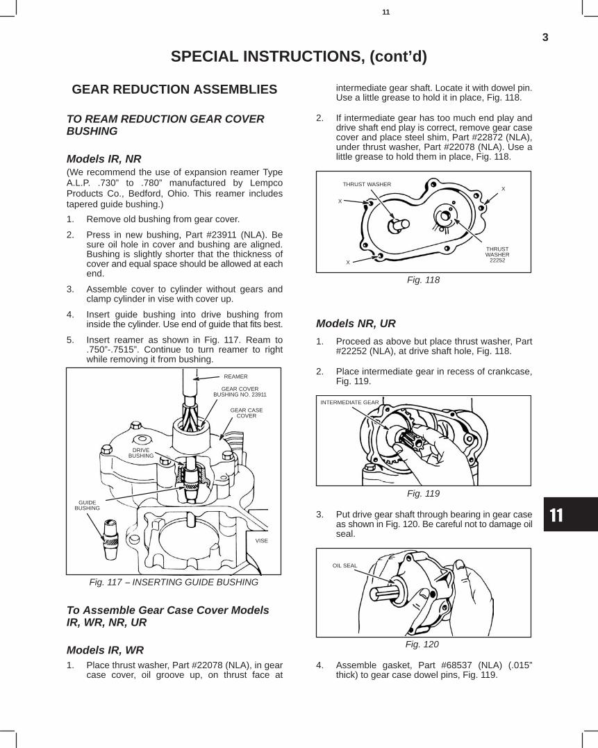
3
11
SPECIAL INSTRUCTIONS, (cont’d)
GEAR REDUCTION ASSEMBLIES
TO REAM REDUCTION GEAR COVERBUSHING
Models IR, NR(We recommend the use of expansion reamer TypeA.L.P. .730” to .780” manufactured by LempcoProducts Co., Bedford, Ohio. This reamer includestapered guide bushing.)
1. Remove old bushing from gear cover.
2. Press in new bushing, Part #23911 (NLA). Besure oil hole in cover and bushing are aligned.Bushing is slightly shorter that the thickness ofcover and equal space should be allowed at eachend.
3. Assemble cover to cylinder without gears andclamp cylinder in vise with cover up.
4. Insert guide bushing into drive bushing frominside the cylinder. Use end of guide that fits best.
5. Insert reamer as shown in Fig. 117. Ream to.750”-.7515”. Continue to turn reamer to rightwhile removing it from bushing.
Fig. 117 − INSERTING GUIDE BUSHING
REAMER
GEAR CASECOVER
GEAR COVERBUSHING NO. 23911
DRIVEBUSHING
VISE
GUIDEBUSHING
To Assemble Gear Case Cover ModelsIR, WR, NR, UR
Models IR, WR1. Place thrust washer, Part #22078 (NLA), in gear
case cover, oil groove up, on thrust face at
intermediate gear shaft. Locate it with dowel pin.Use a little grease to hold it in place, Fig. 118.
2. If intermediate gear has too much end play anddrive shaft end play is correct, remove gear casecover and place steel shim, Part #22872 (NLA),under thrust washer, Part #22078 (NLA). Use alittle grease to hold them in place, Fig. 118.
Fig. 118
THRUST WASHER
X
THRUSTWASHER
22252X
X
Models NR, UR
1. Proceed as above but place thrust washer, Part#22252 (NLA), at drive shaft hole, Fig. 118.
2. Place intermediate gear in recess of crankcase,Fig. 119.
Fig. 119
INTERMEDIATE GEAR
3. Put drive gear shaft through bearing in gear caseas shown in Fig. 120. Be careful not to damage oilseal.
Fig. 120
OIL SEAL
4. Assemble gasket, Part #68537 (NLA) (.015”thick) to gear case dowel pins, Fig. 119.
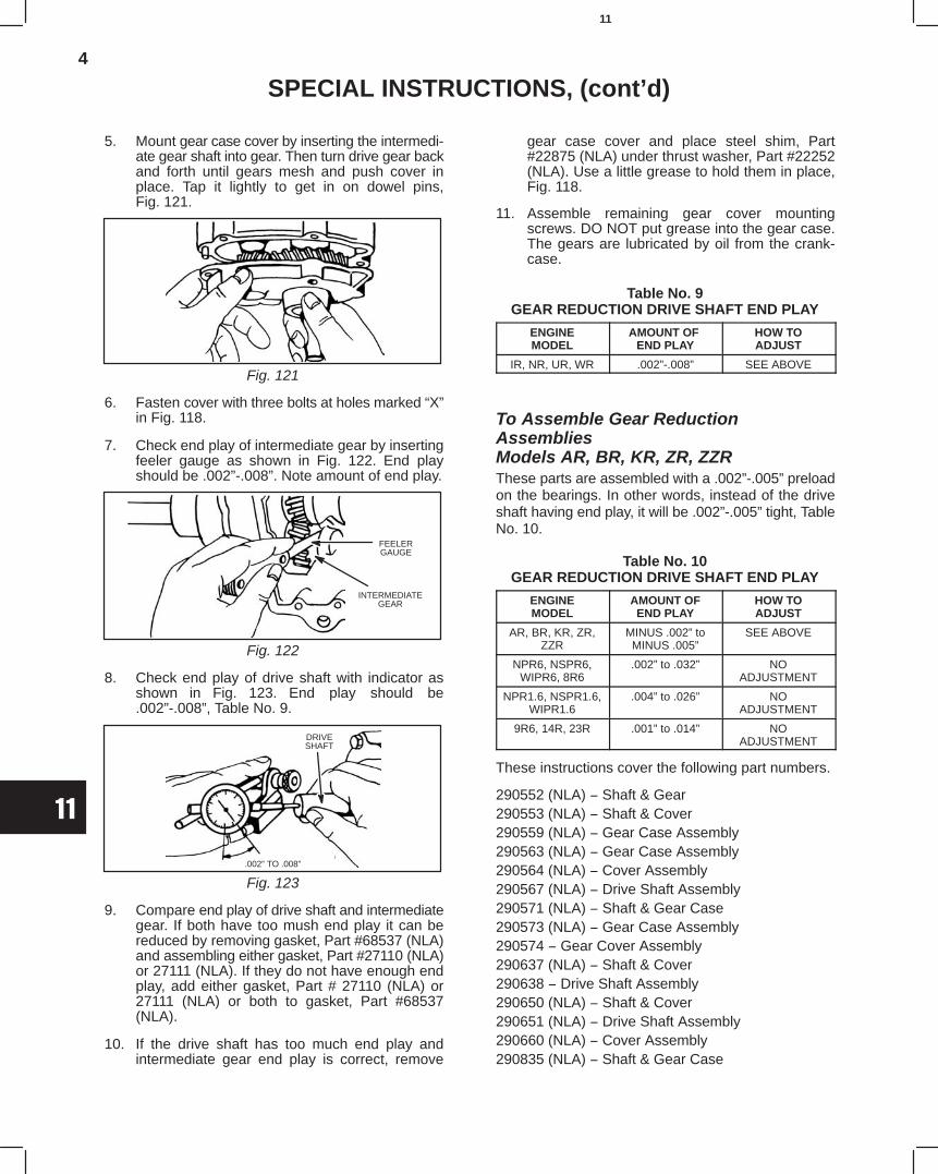
4
11
SPECIAL INSTRUCTIONS, (cont’d)
5. Mount gear case cover by inserting the intermedi-ate gear shaft into gear. Then turn drive gear backand forth until gears mesh and push cover inplace. Tap it lightly to get in on dowel pins,Fig. 121.
Fig. 121
6. Fasten cover with three bolts at holes marked “X”in Fig. 118.
7. Check end play of intermediate gear by insertingfeeler gauge as shown in Fig. 122. End playshould be .002”-.008”. Note amount of end play.
Fig. 122
FEELERGAUGE
INTERMEDIATEGEAR
8. Check end play of drive shaft with indicator asshown in Fig. 123. End play should be.002”-.008”, Table No. 9.
Fig. 123
DRIVESHAFT
.002” TO .008”
9. Compare end play of drive shaft and intermediategear. If both have too mush end play it can bereduced by removing gasket, Part #68537 (NLA)and assembling either gasket, Part #27110 (NLA)or 27111 (NLA). If they do not have enough endplay, add either gasket, Part # 27110 (NLA) or27111 (NLA) or both to gasket, Part #68537(NLA).
10. If the drive shaft has too much end play andintermediate gear end play is correct, remove
gear case cover and place steel shim, Part#22875 (NLA) under thrust washer, Part #22252(NLA). Use a little grease to hold them in place,Fig. 118.
11. Assemble remaining gear cover mountingscrews. DO NOT put grease into the gear case.The gears are lubricated by oil from the crank-case.
Table No. 9GEAR REDUCTION DRIVE SHAFT END PLAY
ENGINEMODEL
AMOUNT OF END PLAY
HOW TOADJUST
IR, NR, UR, WR .002”-.008” SEE ABOVE
To Assemble Gear ReductionAssembliesModels AR, BR, KR, ZR, ZZRThese parts are assembled with a .002”-.005” preloadon the bearings. In other words, instead of the driveshaft having end play, it will be .002”-.005” tight, TableNo. 10.
Table No. 10GEAR REDUCTION DRIVE SHAFT END PLAY
ENGINEMODEL
AMOUNT OFEND PLAY
HOW TOADJUST
AR, BR, KR, ZR,ZZR
MINUS .002” toMINUS .005”
SEE ABOVE
NPR6, NSPR6,WIPR6, 8R6
.002” to .032” NOADJUSTMENT
NPR1.6, NSPR1.6,WIPR1.6
.004” to .026” NOADJUSTMENT
9R6, 14R, 23R .001” to .014” NOADJUSTMENT
These instructions cover the following part numbers.
290552 (NLA) − Shaft & Gear290553 (NLA) − Shaft & Cover290559 (NLA) − Gear Case Assembly290563 (NLA) − Gear Case Assembly290564 (NLA) − Cover Assembly290567 (NLA) − Drive Shaft Assembly290571 (NLA) − Shaft & Gear Case290573 (NLA) − Gear Case Assembly290574 − Gear Cover Assembly290637 (NLA) − Shaft & Cover290638 − Drive Shaft Assembly290650 (NLA) − Shaft & Cover290651 (NLA) − Drive Shaft Assembly290660 (NLA) − Cover Assembly290835 (NLA) − Shaft & Gear Case
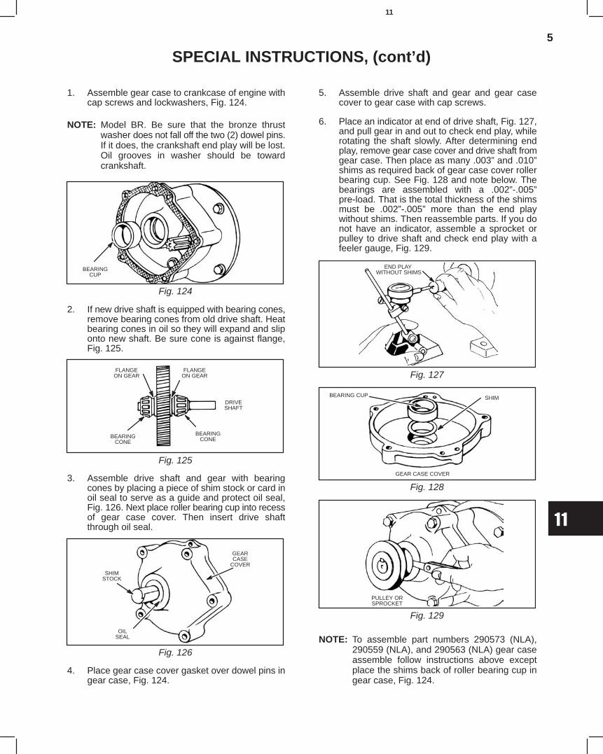
5
11
SPECIAL INSTRUCTIONS, (cont’d)
1. Assemble gear case to crankcase of engine withcap screws and lockwashers, Fig. 124.
NOTE: Model BR. Be sure that the bronze thrustwasher does not fall off the two (2) dowel pins.If it does, the crankshaft end play will be lost.Oil grooves in washer should be towardcrankshaft.
Fig. 124
BEARINGCUP
2. If new drive shaft is equipped with bearing cones,remove bearing cones from old drive shaft. Heatbearing cones in oil so they will expand and sliponto new shaft. Be sure cone is against flange,Fig. 125.
Fig. 125
FLANGEON GEAR
DRIVESHAFT
BEARINGCONE
FLANGEON GEAR
BEARINGCONE
3. Assemble drive shaft and gear with bearingcones by placing a piece of shim stock or card inoil seal to serve as a guide and protect oil seal,Fig. 126. Next place roller bearing cup into recessof gear case cover. Then insert drive shaftthrough oil seal.
Fig. 126
GEARCASE
COVER
SHIMSTOCK
OILSEAL
4. Place gear case cover gasket over dowel pins ingear case, Fig. 124.
5. Assemble drive shaft and gear and gear casecover to gear case with cap screws.
6. Place an indicator at end of drive shaft, Fig. 127,and pull gear in and out to check end play, whilerotating the shaft slowly. After determining endplay, remove gear case cover and drive shaft fromgear case. Then place as many .003” and .010”shims as required back of gear case cover rollerbearing cup. See Fig. 128 and note below. Thebearings are assembled with a .002”-.005”pre-load. That is the total thickness of the shimsmust be .002”-.005” more than the end playwithout shims. Then reassemble parts. If you donot have an indicator, assemble a sprocket orpulley to drive shaft and check end play with afeeler gauge, Fig. 129.
Fig. 127
END PLAY WITHOUT SHIMS
Fig. 128
SHIMBEARING CUP
GEAR CASE COVER
Fig. 129
PULLEY ORSPROCKET
NOTE: To assemble part numbers 290573 (NLA),290559 (NLA), and 290563 (NLA) gear caseassemble follow instructions above exceptplace the shims back of roller bearing cup ingear case, Fig. 124.

6
11
SPECIAL INSTRUCTIONS, (cont’d)
GEAR REDUCTION, MODELSERIES CAST IRON N, 6, 8,
ALUMINUM 6B, 8B, 60000, 80000,100200, 110000, 130000
To Drain and Disassemble GearReduction
1. Note position of gear reduction assembly onengine.
2. Remove oil vent plug.
3. Loosen four cap screws holding gear case coverassembly.
4. Pull cover away from gear case assembly to draingear case.
5. After gear case is drained, remove screws andcover, Fig. 130.
Fig. 130 − DRAINING GEAR REDUCTIONAND REMOVING COVER
GEARCASE
COVER
CAPSCREWS
VENT PLUG(WITH HOLE)
To Remove Output Gear-PTO ShaftAssembly and Gear Case Assembly
1. Remove drive shaft assembly from gear case.
2. Bend down two screw locks if so equipped, andremove four cap screws.
3. Slide gear case off engine, Fig. 131.
Fig. 131 − REMOVING DRIVE GEAR AND GEAR CASE
OUTPUTGEAR−PTO
SHAFTASSEMBLYOPTIONAL LOCKS
GEAR CASE
LOCKTABS
(OPTIONAL)
To Inspect Output Gear-PTO Shaft, GearCase and Cover AssembliesInspect seals for cracks, tears, or hardening. Replaceseals if damaged or hard. Inspect crankshaft piniongear and drive gear for worn, cracked, or chippedteeth. Replace if damaged or worn. Inspect gear caseand cover for cracks, damaged mounting or gasketsurfaces. Replace if damaged.
To ASSEMBLE GEAR REDUCTION
To Install SealsInstall seals with sealing lip towards inside of gear caseor cover assemblies until seal is flush with case orcover, Fig. 132.
Fig. 132 − INSTALLING SEALS
SEALINGLIP
GEAR CASEASSEMBLY ENGINE SIDE
SEALINGLIP
COVERASSEMBLY ENGINE SIDE
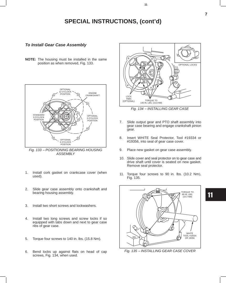
7
11
SPECIAL INSTRUCTIONS, (cont’d)
To Install Gear Case Assembly
NOTE: The housing must be installed in the sameposition as when removed, Fig. 133.
Fig. 133 − POSITIONING BEARING HOUSINGASSEMBLY
ENGINECRANKSHAFT
OPTIONAL12 O’CLOCKPOSITION
OPTIONAL6 O’CLOCKPOSITION
STANDARD9 O’CLOCKPOSITION
OPTIONAL3 O’CLOCKPOSITION
1. Install cork gasket on crankcase cover (whenused).
2. Slide gear case assembly onto crankshaft andbearing housing assembly.
3. Install two short screws and lockwashers.
4. Install two long screws and screw locks if soequipped with tabs down and next to gear caseribs of gear case.
5. Torque four screws to 140 in. lbs. (15.8 Nm).
6. Bend locks up against flats on head of capscrews, Fig. 134, when used.
Fig. 134 − INSTALLING GEAR CASE
LOCKTABS
(OPTIONAL)
OPTIONAL LOCKS
TORQUE TO140 IN. LBS. (15.8 NM)
7. Slide output gear and PTO shaft assembly intogear case bearing and engage crankshaft piniongear.
8. Insert WHITE Seal Protector, Tool #19334 or#19356, into seal of gear case cover.
9. Place new gasket on gear case assembly.
10. Slide cover and seal protector on to gear case anddrive shaft until cover is seated on new gasket.Remove seal protector.
11. Torque four screws to 90 in. lbs. (10.2 Nm),Fig. 135.
Fig. 135 − INSTALLING GEAR CASE COVER
WHITETOOL #19334
OR 19356
TORQUE TO90 IN. LBS.(10.2 NM)
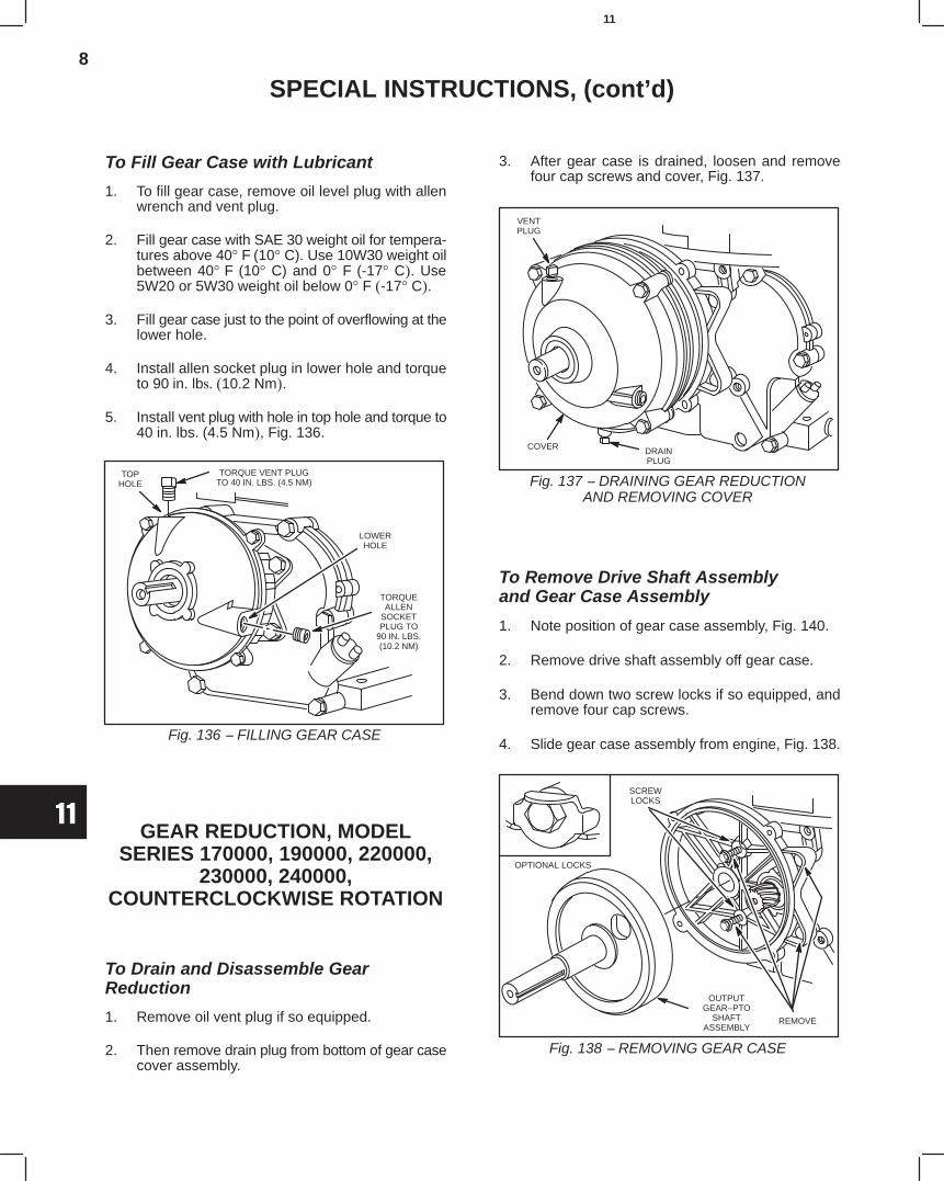
8
11
SPECIAL INSTRUCTIONS, (cont’d)
To Fill Gear Case with Lubricant
1. To fill gear case, remove oil level plug with allenwrench and vent plug.
2. Fill gear case with SAE 30 weight oil for tempera-tures above 40° F (10° C). Use 10W30 weight oilbetween 40° F (10° C) and 0° F (-17° C). Use5W20 or 5W30 weight oil below 0° F (-17° C).
3. Fill gear case just to the point of overflowing at thelower hole.
4. Install allen socket plug in lower hole and torqueto 90 in. lbs. (10.2 Nm).
5. Install vent plug with hole in top hole and torque to40 in. lbs. (4.5 Nm), Fig. 136.
Fig. 136 − FILLING GEAR CASE
TOPHOLE
TORQUE VENT PLUGTO 40 IN. LBS. (4.5 NM)
LOWERHOLE
TORQUEALLEN
SOCKETPLUG TO
90 IN. LBS.(10.2 NM)
GEAR REDUCTION, MODELSERIES 170000, 190000, 220000,
230000, 240000,COUNTERCLOCKWISE ROTATION
To Drain and Disassemble GearReduction
1. Remove oil vent plug if so equipped.
2. Then remove drain plug from bottom of gear casecover assembly.
3. After gear case is drained, loosen and removefour cap screws and cover, Fig. 137.
Fig. 137 − DRAINING GEAR REDUCTIONAND REMOVING COVER
VENTPLUG
COVER DRAINPLUG
To Remove Drive Shaft Assemblyand Gear Case Assembly
1. Note position of gear case assembly, Fig. 140.
2. Remove drive shaft assembly off gear case.
3. Bend down two screw locks if so equipped, andremove four cap screws.
4. Slide gear case assembly from engine, Fig. 138.
Fig. 138 − REMOVING GEAR CASE
OPTIONAL LOCKS
OUTPUTGEAR−PTO
SHAFTASSEMBLY
REMOVE
SCREWLOCKS
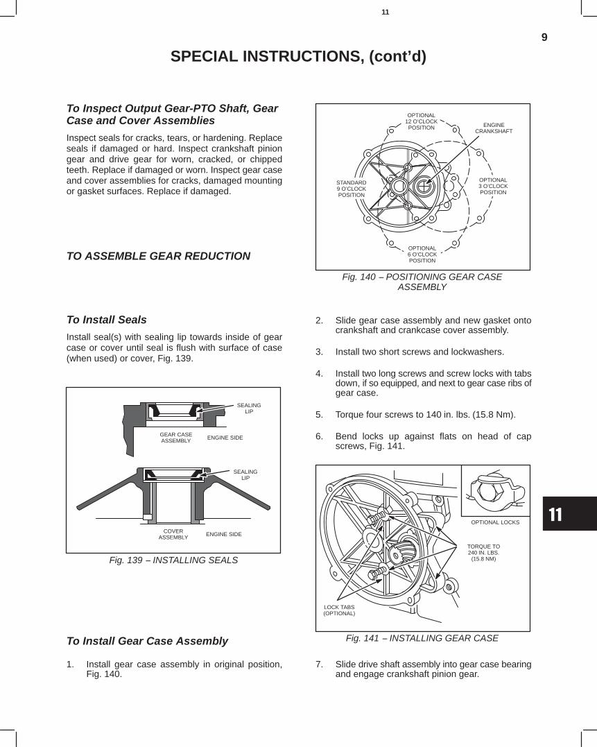
9
11
SPECIAL INSTRUCTIONS, (cont’d)
To Inspect Output Gear-PTO Shaft, GearCase and Cover Assemblies
Inspect seals for cracks, tears, or hardening. Replaceseals if damaged or hard. Inspect crankshaft piniongear and drive gear for worn, cracked, or chippedteeth. Replace if damaged or worn. Inspect gear caseand cover assemblies for cracks, damaged mountingor gasket surfaces. Replace if damaged.
TO ASSEMBLE GEAR REDUCTION
To Install Seals
Install seal(s) with sealing lip towards inside of gearcase or cover until seal is flush with surface of case(when used) or cover, Fig. 139.
Fig. 139 − INSTALLING SEALS
SEALINGLIP
GEAR CASEASSEMBLY ENGINE SIDE
SEALINGLIP
COVERASSEMBLY ENGINE SIDE
To Install Gear Case Assembly
1. Install gear case assembly in original position,Fig. 140.
Fig. 140 − POSITIONING GEAR CASEASSEMBLY
ENGINECRANKSHAFT
OPTIONAL3 O’CLOCKPOSITION
OPTIONAL12 O’CLOCKPOSITION
OPTIONAL6 O’CLOCKPOSITION
STANDARD9 O’CLOCKPOSITION
2. Slide gear case assembly and new gasket ontocrankshaft and crankcase cover assembly.
3. Install two short screws and lockwashers.
4. Install two long screws and screw locks with tabsdown, if so equipped, and next to gear case ribs ofgear case.
5. Torque four screws to 140 in. lbs. (15.8 Nm).
6. Bend locks up against flats on head of capscrews, Fig. 141.
Fig. 141 − INSTALLING GEAR CASE
OPTIONAL LOCKS
TORQUE TO240 IN. LBS.
(15.8 NM)
LOCK TABS(OPTIONAL)
7. Slide drive shaft assembly into gear case bearingand engage crankshaft pinion gear.
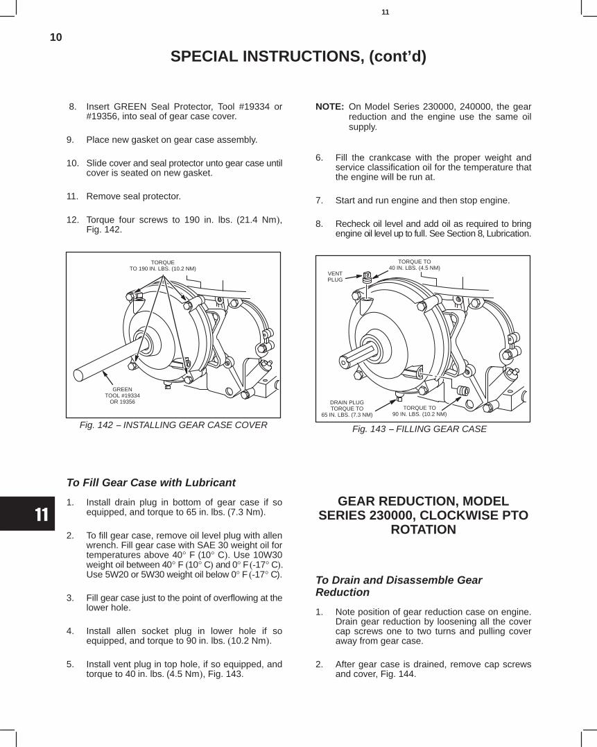
10
11
SPECIAL INSTRUCTIONS, (cont’d)
8. Insert GREEN Seal Protector, Tool #19334 or#19356, into seal of gear case cover.
9. Place new gasket on gear case assembly.
10. Slide cover and seal protector unto gear case untilcover is seated on new gasket.
11. Remove seal protector.
12. Torque four screws to 190 in. lbs. (21.4 Nm),Fig. 142.
Fig. 142 − INSTALLING GEAR CASE COVER
TORQUETO 190 IN. LBS. (10.2 NM)
GREENTOOL #19334
OR 19356
To Fill Gear Case with Lubricant
1. Install drain plug in bottom of gear case if soequipped, and torque to 65 in. lbs. (7.3 Nm).
2. To fill gear case, remove oil level plug with allenwrench. Fill gear case with SAE 30 weight oil fortemperatures above 40° F (10° C). Use 10W30weight oil between 40° F (10° C) and 0° F (-17° C).Use 5W20 or 5W30 weight oil below 0° F (-17° C).
3. Fill gear case just to the point of overflowing at thelower hole.
4. Install allen socket plug in lower hole if soequipped, and torque to 90 in. lbs. (10.2 Nm).
5. Install vent plug in top hole, if so equipped, andtorque to 40 in. lbs. (4.5 Nm), Fig. 143.
NOTE: On Model Series 230000, 240000, the gearreduction and the engine use the same oilsupply.
6. Fill the crankcase with the proper weight andservice classification oil for the temperature thatthe engine will be run at.
7. Start and run engine and then stop engine.
8. Recheck oil level and add oil as required to bringengine oil level up to full. See Section 8, Lubrication.
Fig. 143 − FILLING GEAR CASE
VENTPLUG
TORQUE TO40 IN. LBS. (4.5 NM)
DRAIN PLUGTORQUE TO
65 IN. LBS. (7.3 NM)TORQUE TO
90 IN. LBS. (10.2 NM)
GEAR REDUCTION, MODELSERIES 230000, CLOCKWISE PTO
ROTATION
To Drain and Disassemble GearReduction
1. Note position of gear reduction case on engine.Drain gear reduction by loosening all the covercap screws one to two turns and pulling coveraway from gear case.
2. After gear case is drained, remove cap screwsand cover, Fig. 144.
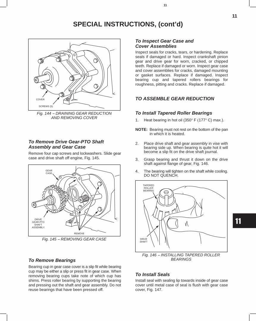
11
11
SPECIAL INSTRUCTIONS, (cont’d)
Fig. 144 − DRAINING GEAR REDUCTIONAND REMOVING COVER
COVER
SCREWS (5)
To Remove Drive Gear-PTO ShaftAssembly and Gear CaseRemove four cap screws and lockwashers. Slide gearcase and drive shaft off engine, Fig. 145.
Fig. 145 − REMOVING GEAR CASE
GEARCASE
DRIVEGEAR-PTO
SHAFTASSEMBLY
REMOVE
To Remove BearingsBearing cup in gear case cover is a slip fit while bearingcup may be either a slip or press fit in gear case. Whenremoving bearing cups take note of which cup hasshims. Press roller bearing by supporting the bearingand pressing out the shaft and gear assembly. Do notreuse bearings that have been pressed off.
To Inspect Gear Case andCover AssembliesInspect seals for cracks, tears, or hardening. Replaceseals if damaged or hard. Inspect crankshaft piniongear and drive gear for worn, cracked, or chippedteeth. Replace if damaged or worn. Inspect gear caseand cover assemblies for cracks, damaged mountingor gasket surfaces. Replace if damaged. Inspectbearing cup and tapered rollers bearings forroughness, pitting and cracks. Replace if damaged.
TO ASSEMBLE GEAR REDUCTION
To Install Tapered Roller Bearings1. Heat bearing in hot oil (350° F (177° C) max.).
NOTE: Bearing must not rest on the bottom of the panin which it is heated.
2. Place drive shaft and gear assembly in vise withbearing side up. When bearing is quite hot it willbecome a slip fit on the drive shaft journal.
3. Grasp bearing and thrust it down on the driveshaft against flange of gear, Fig. 146.
4. The bearing will tighten on the shaft while cooling.DO NOT QUENCH.
Fig. 146 − INSTALLING TAPERED ROLLERBEARINGS
TAPEREDROLLERBEARING
DRIVESHAFT
To Install SealsInstall seal with sealing lip towards inside of gear casecover until metal case of seal is flush with gear casecover, Fig. 147.
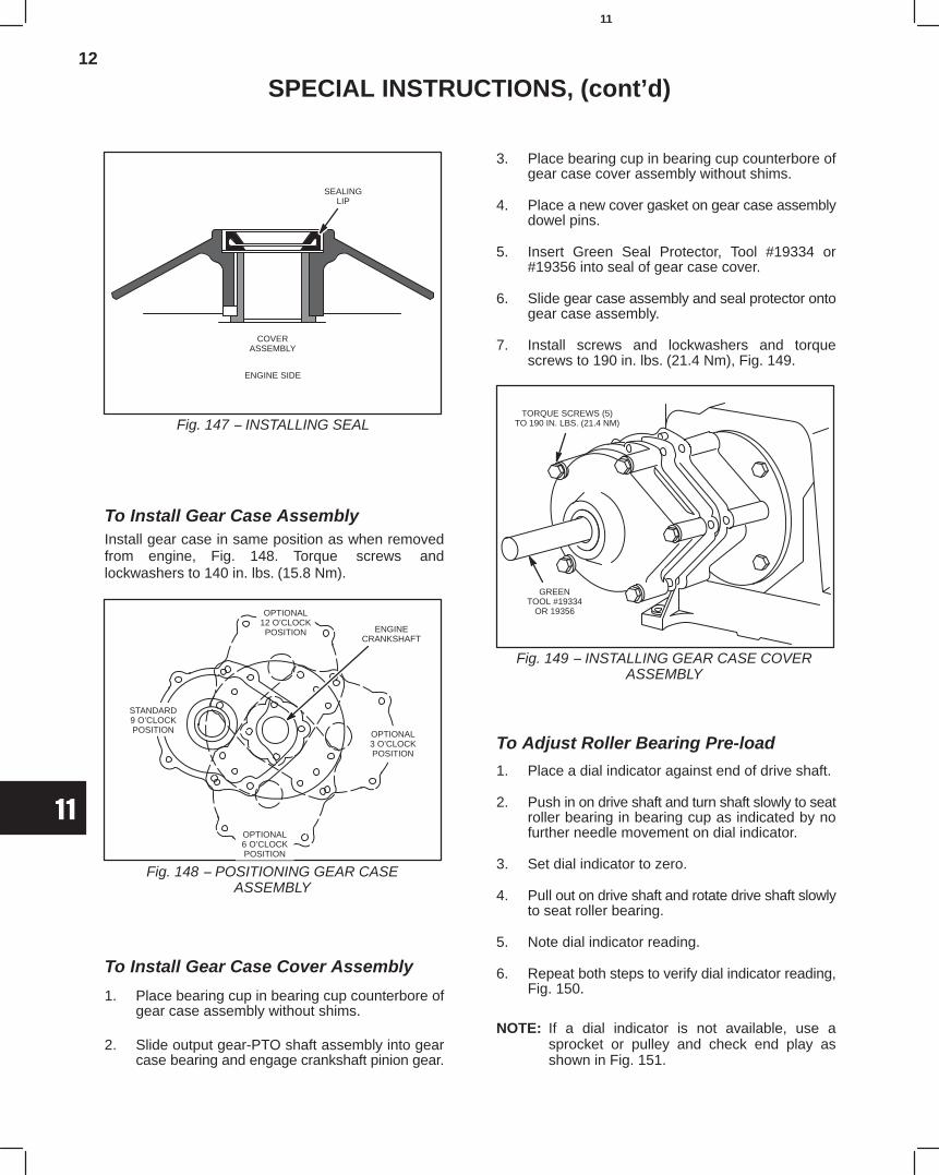
12
11
SPECIAL INSTRUCTIONS, (cont’d)
Fig. 147 − INSTALLING SEAL
SEALINGLIP
COVERASSEMBLY
ENGINE SIDE
To Install Gear Case AssemblyInstall gear case in same position as when removedfrom engine, Fig. 148. Torque screws andlockwashers to 140 in. lbs. (15.8 Nm).
Fig. 148 − POSITIONING GEAR CASEASSEMBLY
ENGINECRANKSHAFT
OPTIONAL12 O’CLOCKPOSITION
OPTIONAL6 O’CLOCKPOSITION
STANDARD9 O’CLOCKPOSITION OPTIONAL
3 O’CLOCKPOSITION
To Install Gear Case Cover Assembly
1. Place bearing cup in bearing cup counterbore ofgear case assembly without shims.
2. Slide output gear-PTO shaft assembly into gearcase bearing and engage crankshaft pinion gear.
3. Place bearing cup in bearing cup counterbore ofgear case cover assembly without shims.
4. Place a new cover gasket on gear case assemblydowel pins.
5. Insert Green Seal Protector, Tool #19334 or#19356 into seal of gear case cover.
6. Slide gear case assembly and seal protector ontogear case assembly.
7. Install screws and lockwashers and torquescrews to 190 in. lbs. (21.4 Nm), Fig. 149.
Fig. 149 − INSTALLING GEAR CASE COVERASSEMBLY
GREENTOOL #19334
OR 19356
TORQUE SCREWS (5)TO 190 IN. LBS. (21.4 NM)
To Adjust Roller Bearing Pre-load
1. Place a dial indicator against end of drive shaft.
2. Push in on drive shaft and turn shaft slowly to seatroller bearing in bearing cup as indicated by nofurther needle movement on dial indicator.
3. Set dial indicator to zero.
4. Pull out on drive shaft and rotate drive shaft slowlyto seat roller bearing.
5. Note dial indicator reading.
6. Repeat both steps to verify dial indicator reading,Fig. 150.
NOTE: If a dial indicator is not available, use asprocket or pulley and check end play asshown in Fig. 151.
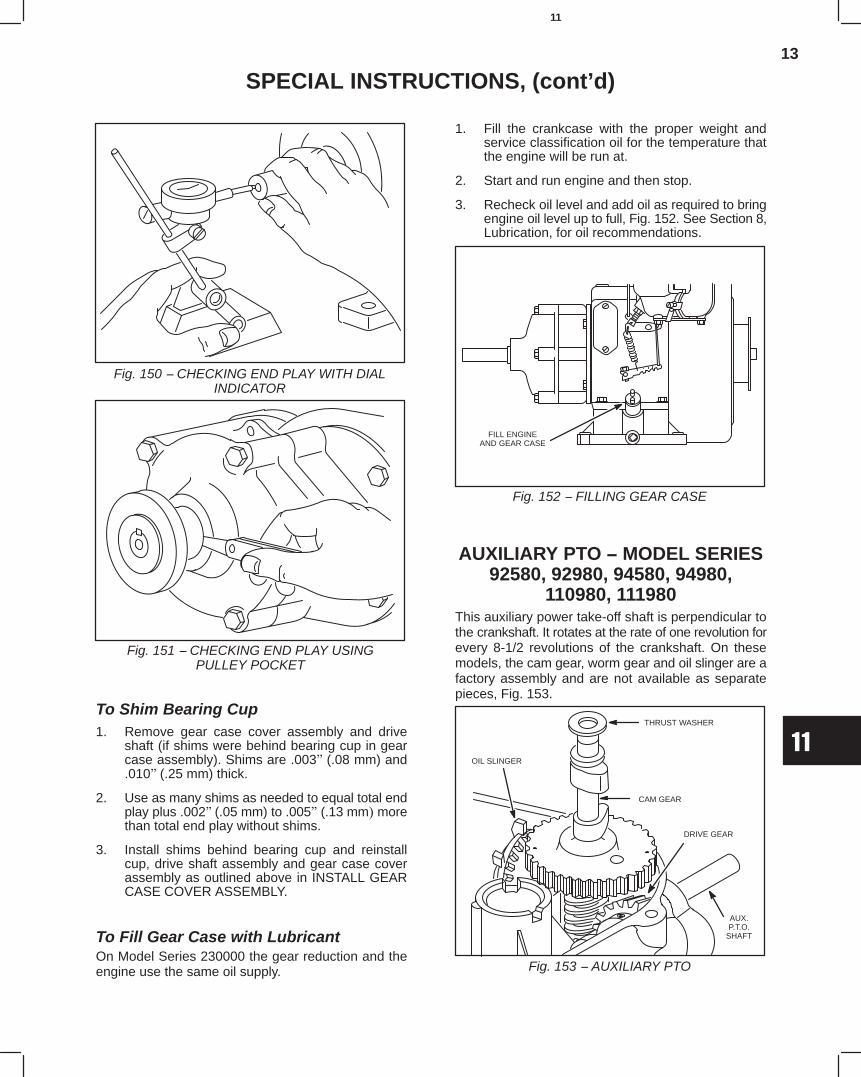
13
11
SPECIAL INSTRUCTIONS, (cont’d)
Fig. 150 − CHECKING END PLAY WITH DIALINDICATOR
Fig. 151 − CHECKING END PLAY USINGPULLEY POCKET
To Shim Bearing Cup1. Remove gear case cover assembly and drive
shaft (if shims were behind bearing cup in gearcase assembly). Shims are .003" (.08 mm) and.010" (.25 mm) thick.
2. Use as many shims as needed to equal total endplay plus .002" (.05 mm) to .005" (.13 mm) morethan total end play without shims.
3. Install shims behind bearing cup and reinstallcup, drive shaft assembly and gear case coverassembly as outlined above in INSTALL GEARCASE COVER ASSEMBLY.
To Fill Gear Case with LubricantOn Model Series 230000 the gear reduction and theengine use the same oil supply.
1. Fill the crankcase with the proper weight andservice classification oil for the temperature thatthe engine will be run at.
2. Start and run engine and then stop.
3. Recheck oil level and add oil as required to bringengine oil level up to full, Fig. 152. See Section 8,Lubrication, for oil recommendations.
Fig. 152 − FILLING GEAR CASE
FILL ENGINEAND GEAR CASE
AUXILIARY PTO − MODEL SERIES92580, 92980, 94580, 94980,
110980, 111980This auxiliary power take-off shaft is perpendicular tothe crankshaft. It rotates at the rate of one revolution forevery 8-1/2 revolutions of the crankshaft. On thesemodels, the cam gear, worm gear and oil slinger are afactory assembly and are not available as separatepieces, Fig. 153.
Fig. 153 − AUXILIARY PTO
CAM GEAR
THRUST WASHER
OIL SLINGER
DRIVE GEAR
AUX.P.T.O.
SHAFT
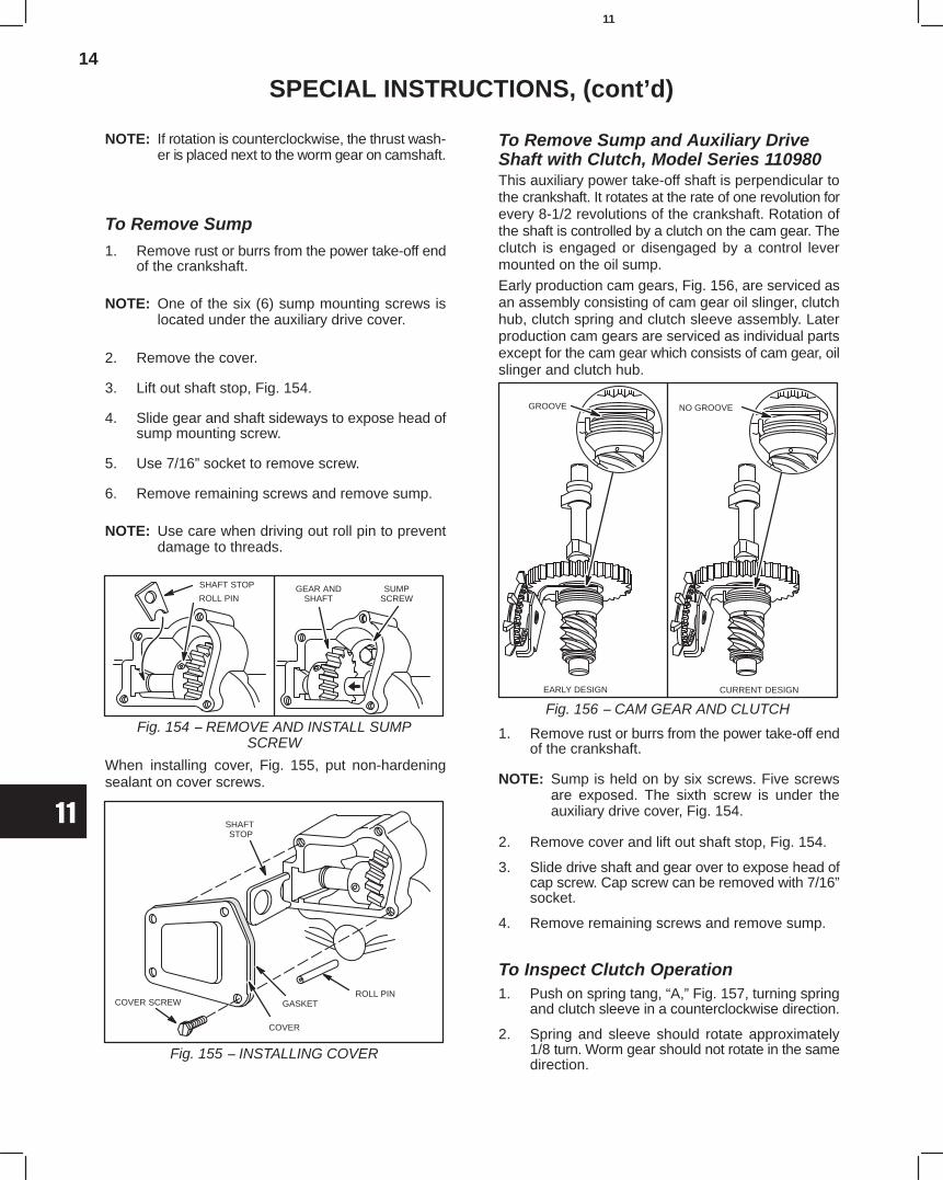
14
11
SPECIAL INSTRUCTIONS, (cont’d)
NOTE: If rotation is counterclockwise, the thrust wash-er is placed next to the worm gear on camshaft.
To Remove Sump1. Remove rust or burrs from the power take-off end
of the crankshaft.
NOTE: One of the six (6) sump mounting screws islocated under the auxiliary drive cover.
2. Remove the cover.
3. Lift out shaft stop, Fig. 154.
4. Slide gear and shaft sideways to expose head ofsump mounting screw.
5. Use 7/16” socket to remove screw.
6. Remove remaining screws and remove sump.
NOTE: Use care when driving out roll pin to preventdamage to threads.
Fig. 154 − REMOVE AND INSTALL SUMPSCREW
GEAR ANDSHAFT
SHAFT STOP SUMPSCREWROLL PIN
When installing cover, Fig. 155, put non-hardeningsealant on cover screws.
Fig. 155 − INSTALLING COVER
ROLL PINCOVER SCREW GASKET
COVER
SHAFT STOP
To Remove Sump and Auxiliary DriveShaft with Clutch, Model Series 110980This auxiliary power take-off shaft is perpendicular tothe crankshaft. It rotates at the rate of one revolution forevery 8-1/2 revolutions of the crankshaft. Rotation ofthe shaft is controlled by a clutch on the cam gear. Theclutch is engaged or disengaged by a control levermounted on the oil sump.Early production cam gears, Fig. 156, are serviced asan assembly consisting of cam gear oil slinger, clutchhub, clutch spring and clutch sleeve assembly. Laterproduction cam gears are serviced as individual partsexcept for the cam gear which consists of cam gear, oilslinger and clutch hub.
Fig. 156 − CAM GEAR AND CLUTCH
GROOVE NO GROOVE
CURRENT DESIGNEARLY DESIGN
1. Remove rust or burrs from the power take-off endof the crankshaft.
NOTE: Sump is held on by six screws. Five screwsare exposed. The sixth screw is under theauxiliary drive cover, Fig. 154.
2. Remove cover and lift out shaft stop, Fig. 154.
3. Slide drive shaft and gear over to expose head ofcap screw. Cap screw can be removed with 7/16”socket.
4. Remove remaining screws and remove sump.
To Inspect Clutch Operation1. Push on spring tang, “A,” Fig. 157, turning spring
and clutch sleeve in a counterclockwise direction.
2. Spring and sleeve should rotate approximately1/8 turn. Worm gear should not rotate in the samedirection.
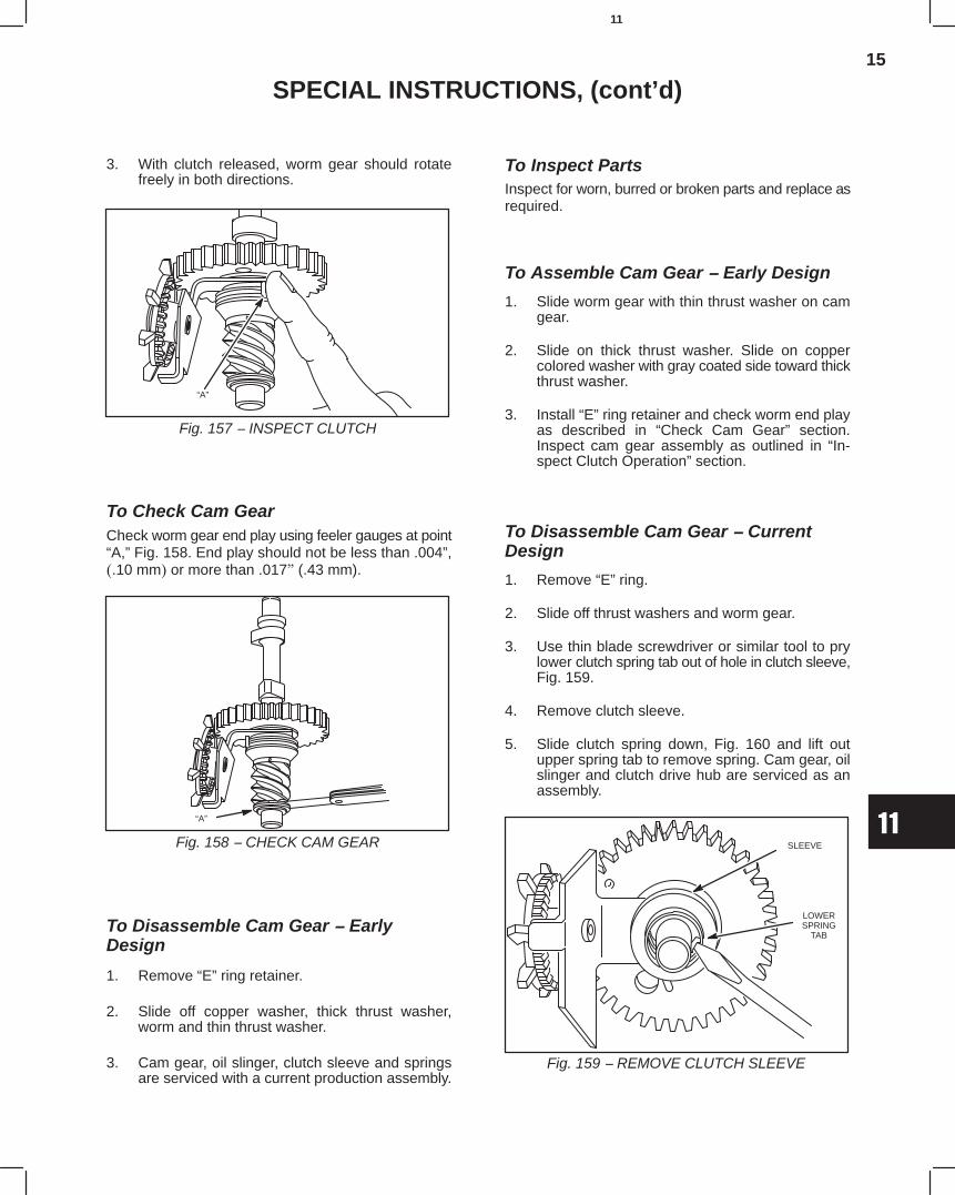
15
11
SPECIAL INSTRUCTIONS, (cont’d)
3. With clutch released, worm gear should rotatefreely in both directions.
Fig. 157 − INSPECT CLUTCH
“A”
To Check Cam GearCheck worm gear end play using feeler gauges at point“A,” Fig. 158. End play should not be less than .004”,(.10 mm) or more than .017" (.43 mm).
Fig. 158 − CHECK CAM GEAR
“A”
To Disassemble Cam Gear − EarlyDesign
1. Remove “E” ring retainer.
2. Slide off copper washer, thick thrust washer,worm and thin thrust washer.
3. Cam gear, oil slinger, clutch sleeve and springsare serviced with a current production assembly.
To Inspect PartsInspect for worn, burred or broken parts and replace asrequired.
To Assemble Cam Gear − Early Design
1. Slide worm gear with thin thrust washer on camgear.
2. Slide on thick thrust washer. Slide on coppercolored washer with gray coated side toward thickthrust washer.
3. Install “E” ring retainer and check worm end playas described in “Check Cam Gear” section.Inspect cam gear assembly as outlined in “In-spect Clutch Operation” section.
To Disassemble Cam Gear − CurrentDesign
1. Remove “E” ring.
2. Slide off thrust washers and worm gear.
3. Use thin blade screwdriver or similar tool to prylower clutch spring tab out of hole in clutch sleeve,Fig. 159.
4. Remove clutch sleeve.
5. Slide clutch spring down, Fig. 160 and lift outupper spring tab to remove spring. Cam gear, oilslinger and clutch drive hub are serviced as anassembly.
Fig. 159 − REMOVE CLUTCH SLEEVE
LOWERSPRING
TAB
SLEEVE
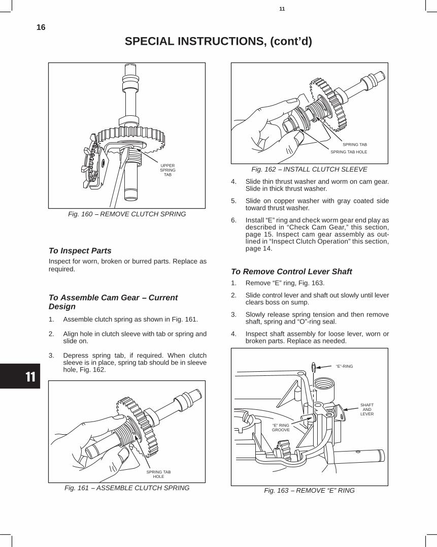
16
11
SPECIAL INSTRUCTIONS, (cont’d)
Fig. 160 − REMOVE CLUTCH SPRING
UPPERSPRING
TAB
To Inspect PartsInspect for worn, broken or burred parts. Replace asrequired.
To Assemble Cam Gear − CurrentDesign
1. Assemble clutch spring as shown in Fig. 161.
2. Align hole in clutch sleeve with tab or spring andslide on.
3. Depress spring tab, if required. When clutchsleeve is in place, spring tab should be in sleevehole, Fig. 162.
Fig. 161 − ASSEMBLE CLUTCH SPRING
SPRING TABHOLE
Fig. 162 − INSTALL CLUTCH SLEEVE
SPRING TAB
SPRING TAB HOLE
4. Slide thin thrust washer and worm on cam gear.Slide in thick thrust washer.
5. Slide on copper washer with gray coated sidetoward thrust washer.
6. Install “E” ring and check worm gear end play asdescribed in “Check Cam Gear,” this section,page 15. Inspect cam gear assembly as out-lined in “Inspect Clutch Operation” this section,page 14.
To Remove Control Lever Shaft1. Remove “E” ring, Fig. 163.
2. Slide control lever and shaft out slowly until leverclears boss on sump.
3. Slowly release spring tension and then removeshaft, spring and “O”-ring seal.
4. Inspect shaft assembly for loose lever, worn orbroken parts. Replace as needed.
Fig. 163 − REMOVE “E” RING
“E”-RING
“E” RINGGROOVE
SHAFTAND
LEVER
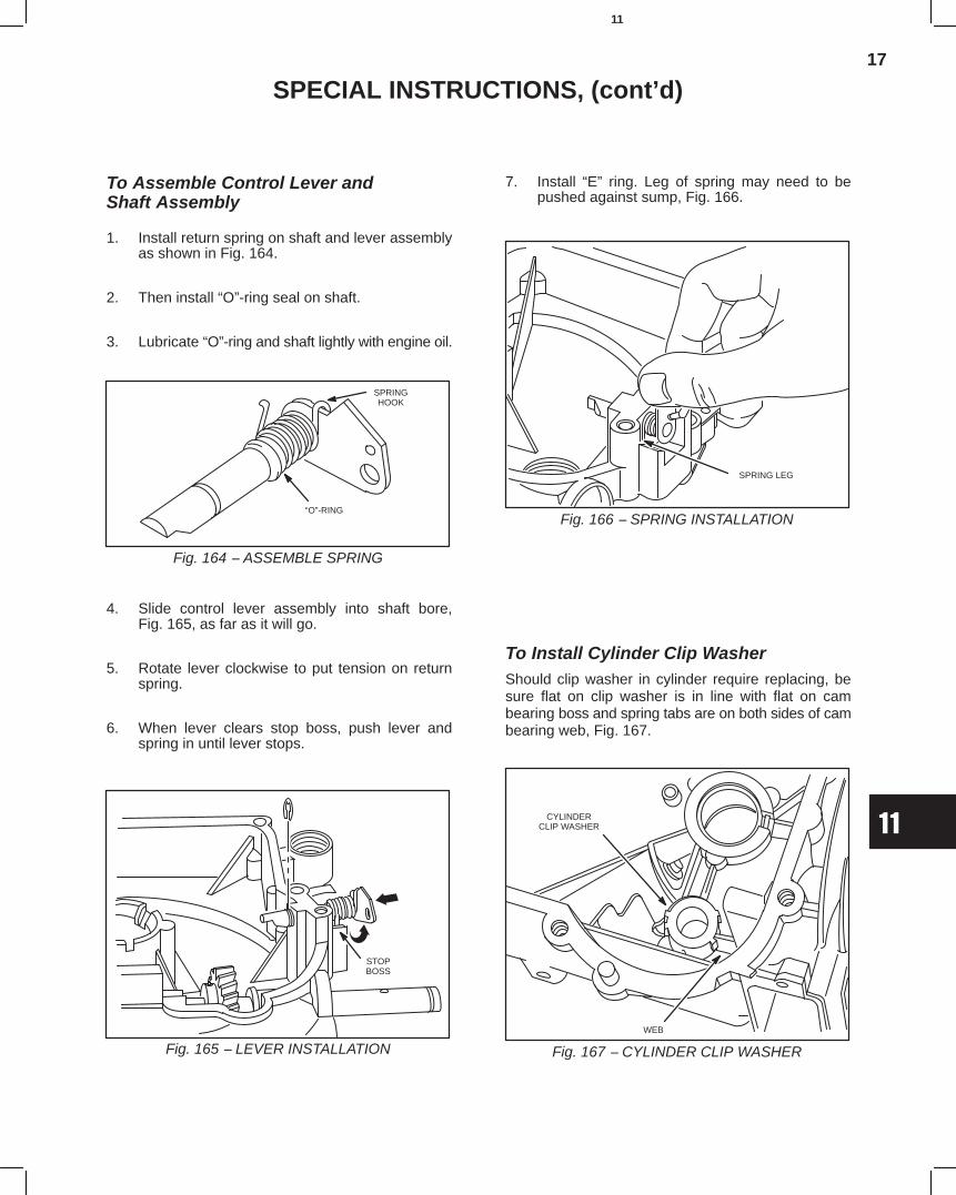
17
11
SPECIAL INSTRUCTIONS, (cont’d)
To Assemble Control Lever andShaft Assembly
1. Install return spring on shaft and lever assemblyas shown in Fig. 164.
2. Then install “O”-ring seal on shaft.
3. Lubricate “O”-ring and shaft lightly with engine oil.
Fig. 164 − ASSEMBLE SPRING
SPRINGHOOK
“O”-RING
4. Slide control lever assembly into shaft bore,Fig. 165, as far as it will go.
5. Rotate lever clockwise to put tension on returnspring.
6. When lever clears stop boss, push lever andspring in until lever stops.
Fig. 165 − LEVER INSTALLATION
STOPBOSS
7. Install “E” ring. Leg of spring may need to bepushed against sump, Fig. 166.
Fig. 166 − SPRING INSTALLATION
SPRING LEG
To Install Cylinder Clip WasherShould clip washer in cylinder require replacing, besure flat on clip washer is in line with flat on cambearing boss and spring tabs are on both sides of cambearing web, Fig. 167.
Fig. 167 − CYLINDER CLIP WASHER
CYLINDERCLIP WASHER
WEB
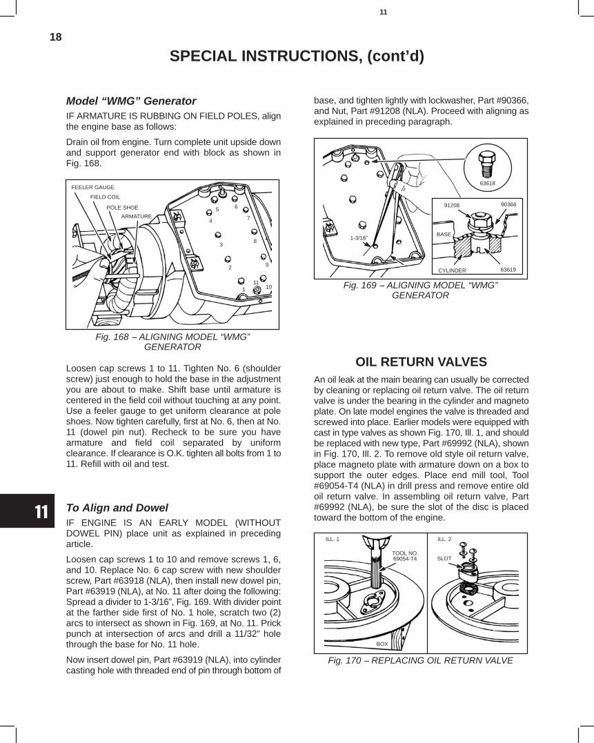
18
11
SPECIAL INSTRUCTIONS, (cont’d)
Model “WMG” GeneratorIF ARMATURE IS RUBBING ON FIELD POLES, alignthe engine base as follows:
Drain oil from engine. Turn complete unit upside downand support generator end with block as shown inFig. 168.
Fig. 168 − ALIGNING MODEL “WMG”GENERATOR
FEELER GAUGE
FIELD COIL
POLE SHOE
ARMATURE
111
10
9
8
7
65
4
3
2
Loosen cap screws 1 to 11. Tighten No. 6 (shoulderscrew) just enough to hold the base in the adjustmentyou are about to make. Shift base until armature iscentered in the field coil without touching at any point.Use a feeler gauge to get uniform clearance at poleshoes. Now tighten carefully, first at No. 6, then at No.11 (dowel pin nut). Recheck to be sure you havearmature and field coil separated by uniformclearance. If clearance is O.K. tighten all bolts from 1 to11. Refill with oil and test.
To Align and DowelIF ENGINE IS AN EARLY MODEL (WITHOUTDOWEL PIN) place unit as explained in precedingarticle.
Loosen cap screws 1 to 10 and remove screws 1, 6,and 10. Replace No. 6 cap screw with new shoulderscrew, Part #63918 (NLA), then install new dowel pin,Part #63919 (NLA), at No. 11 after doing the following:Spread a divider to 1-3/16”, Fig. 169. With divider pointat the farther side first of No. 1 hole, scratch two (2)arcs to intersect as shown in Fig. 169, at No. 11. Prickpunch at intersection of arcs and drill a 11/32” holethrough the base for No. 11 hole.
Now insert dowel pin, Part #63919 (NLA), into cylindercasting hole with threaded end of pin through bottom of
base, and tighten lightly with lockwasher, Part #90366,and Nut, Part #91208 (NLA). Proceed with aligning asexplained in preceding paragraph.
Fig. 169 − ALIGNING MODEL “WMG”GENERATOR
63618
1-3/16”
91208 90366
BASE
CYLINDER 63619
OIL RETURN VALVESAn oil leak at the main bearing can usually be correctedby cleaning or replacing oil return valve. The oil returnvalve is under the bearing in the cylinder and magnetoplate. On late model engines the valve is threaded andscrewed into place. Earlier models were equipped withcast in type valves as shown Fig. 170, Ill. 1, and shouldbe replaced with new type, Part #69992 (NLA), shownin Fig. 170, Ill. 2. To remove old style oil return valve,place magneto plate with armature down on a box tosupport the outer edges. Place end mill tool, Tool#69054-T4 (NLA) in drill press and remove entire oldoil return valve. In assembling oil return valve, Part#69992 (NLA), be sure the slot of the disc is placedtoward the bottom of the engine.
Fig. 170 − REPLACING OIL RETURN VALVE
TOOL NO.69054-T4 SLOT
BOX
ILL. 1 ILL. 2
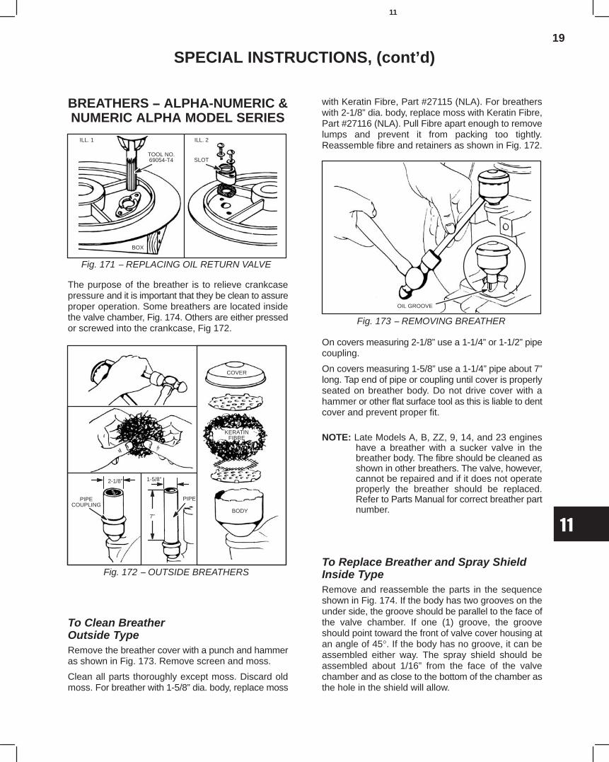
19
11
SPECIAL INSTRUCTIONS, (cont’d)
BREATHERS − ALPHA-NUMERIC &NUMERIC ALPHA MODEL SERIES
Fig. 171 − REPLACING OIL RETURN VALVE
TOOL NO.69054-T4 SLOT
BOX
ILL. 1 ILL. 2
The purpose of the breather is to relieve crankcasepressure and it is important that they be clean to assureproper operation. Some breathers are located insidethe valve chamber, Fig. 174. Others are either pressedor screwed into the crankcase, Fig 172.
Fig. 172 − OUTSIDE BREATHERS
COVER
KERATINFIBRE
BODY7”
PIPE
1-5/8”
PIPECOUPLING
2-1/8”
To Clean BreatherOutside TypeRemove the breather cover with a punch and hammeras shown in Fig. 173. Remove screen and moss.
Clean all parts thoroughly except moss. Discard oldmoss. For breather with 1-5/8” dia. body, replace moss
with Keratin Fibre, Part #27115 (NLA). For breatherswith 2-1/8” dia. body, replace moss with Keratin Fibre,Part #27116 (NLA). Pull Fibre apart enough to removelumps and prevent it from packing too tightly.Reassemble fibre and retainers as shown in Fig. 172.
Fig. 173 − REMOVING BREATHER
OIL GROOVE
On covers measuring 2-1/8” use a 1-1/4” or 1-1/2” pipecoupling.
On covers measuring 1-5/8” use a 1-1/4” pipe about 7”long. Tap end of pipe or coupling until cover is properlyseated on breather body. Do not drive cover with ahammer or other flat surface tool as this is liable to dentcover and prevent proper fit.
NOTE: Late Models A, B, ZZ, 9, 14, and 23 engineshave a breather with a sucker valve in thebreather body. The fibre should be cleaned asshown in other breathers. The valve, however,cannot be repaired and if it does not operateproperly the breather should be replaced.Refer to Parts Manual for correct breather partnumber.
To Replace Breather and Spray ShieldInside TypeRemove and reassemble the parts in the sequenceshown in Fig. 174. If the body has two grooves on theunder side, the groove should be parallel to the face ofthe valve chamber. If one (1) groove, the grooveshould point toward the front of valve cover housing atan angle of 45°. If the body has no groove, it can beassembled either way. The spray shield should beassembled about 1/16” from the face of the valvechamber and as close to the bottom of the chamber asthe hole in the shield will allow.
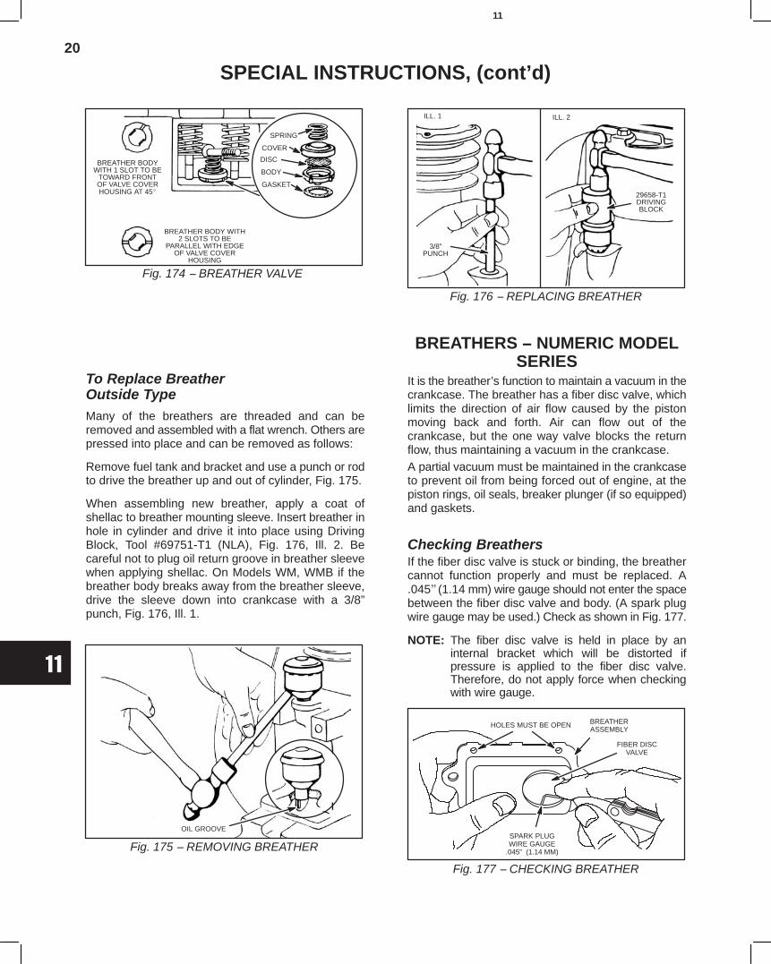
20
11
SPECIAL INSTRUCTIONS, (cont’d)
Fig. 174 − BREATHER VALVE
BREATHER BODYWITH 1 SLOT TO BE
TOWARD FRONTOF VALVE COVERHOUSING AT 45
BREATHER BODY WITH2 SLOTS TO BE
PARALLEL WITH EDGEOF VALVE COVER
HOUSING
SPRING
COVER
DISC
BODY
GASKET
To Replace BreatherOutside TypeMany of the breathers are threaded and can beremoved and assembled with a flat wrench. Others arepressed into place and can be removed as follows:
Remove fuel tank and bracket and use a punch or rodto drive the breather up and out of cylinder, Fig. 175.
When assembling new breather, apply a coat ofshellac to breather mounting sleeve. Insert breather inhole in cylinder and drive it into place using DrivingBlock, Tool #69751-T1 (NLA), Fig. 176, Ill. 2. Becareful not to plug oil return groove in breather sleevewhen applying shellac. On Models WM, WMB if thebreather body breaks away from the breather sleeve,drive the sleeve down into crankcase with a 3/8”punch, Fig. 176, Ill. 1.
Fig. 175 − REMOVING BREATHER
OIL GROOVE
Fig. 176 − REPLACING BREATHER
ILL. 1 ILL. 2
3/8”PUNCH
29658-T1DRIVINGBLOCK
BREATHERS − NUMERIC MODELSERIES
It is the breather’s function to maintain a vacuum in thecrankcase. The breather has a fiber disc valve, whichlimits the direction of air flow caused by the pistonmoving back and forth. Air can flow out of thecrankcase, but the one way valve blocks the returnflow, thus maintaining a vacuum in the crankcase.A partial vacuum must be maintained in the crankcaseto prevent oil from being forced out of engine, at thepiston rings, oil seals, breaker plunger (if so equipped)and gaskets.
Checking BreathersIf the fiber disc valve is stuck or binding, the breathercannot function properly and must be replaced. A.045" (1.14 mm) wire gauge should not enter the spacebetween the fiber disc valve and body. (A spark plugwire gauge may be used.) Check as shown in Fig. 177.
NOTE: The fiber disc valve is held in place by aninternal bracket which will be distorted ifpressure is applied to the fiber disc valve.Therefore, do not apply force when checkingwith wire gauge.
HOLES MUST BE OPEN BREATHERASSEMBLY
FIBER DISCVALVE
SPARK PLUGWIRE GAUGE
.045” (1.14 MM)
Fig. 177 − CHECKING BREATHER
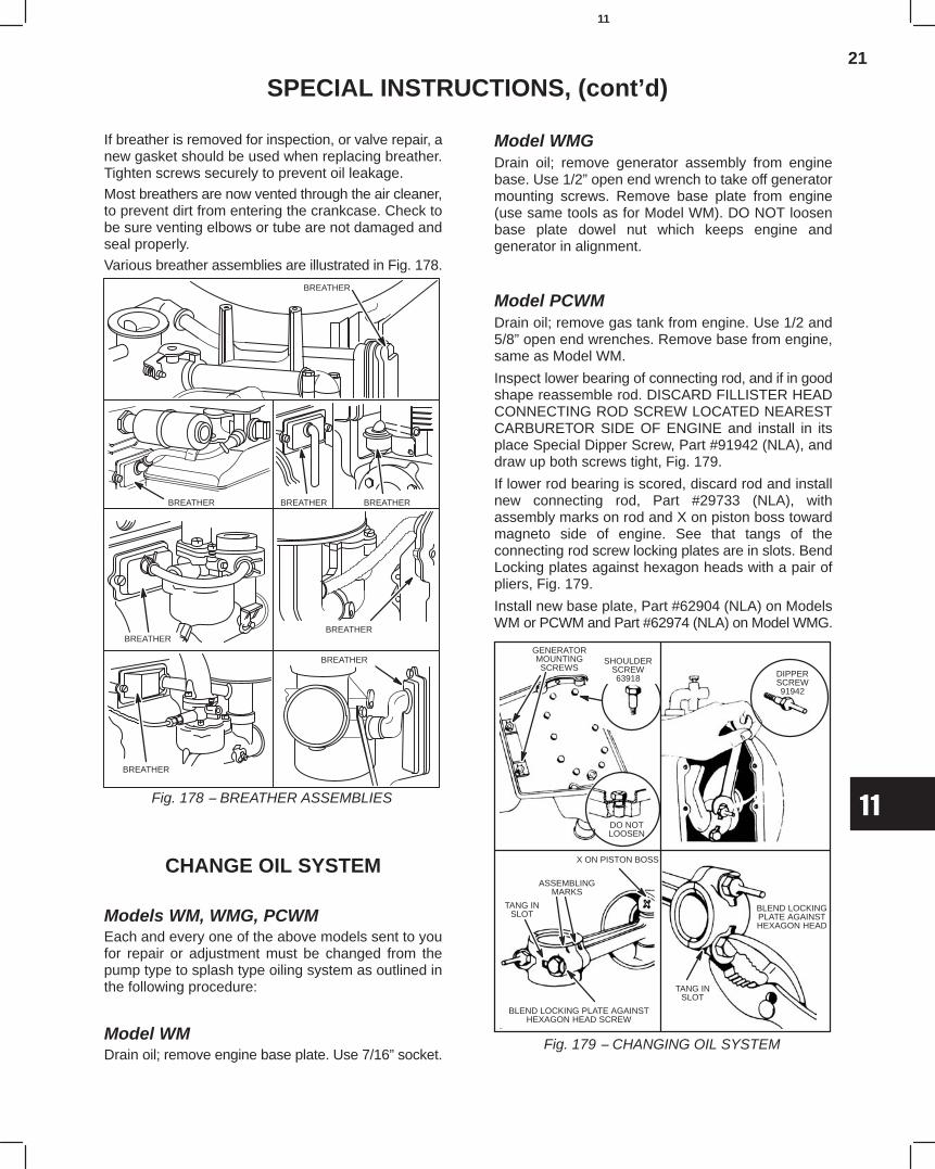
21
11
SPECIAL INSTRUCTIONS, (cont’d)
If breather is removed for inspection, or valve repair, anew gasket should be used when replacing breather.Tighten screws securely to prevent oil leakage.
Most breathers are now vented through the air cleaner,to prevent dirt from entering the crankcase. Check tobe sure venting elbows or tube are not damaged andseal properly.
Various breather assemblies are illustrated in Fig. 178.BREATHER
BREATHERBREATHER BREATHER
BREATHER
BREATHER
Fig. 178 − BREATHER ASSEMBLIES
BREATHER
BREATHER
CHANGE OIL SYSTEM
Models WM, WMG, PCWMEach and every one of the above models sent to youfor repair or adjustment must be changed from thepump type to splash type oiling system as outlined inthe following procedure:
Model WMDrain oil; remove engine base plate. Use 7/16” socket.
Model WMGDrain oil; remove generator assembly from enginebase. Use 1/2” open end wrench to take off generatormounting screws. Remove base plate from engine(use same tools as for Model WM). DO NOT loosenbase plate dowel nut which keeps engine andgenerator in alignment.
Model PCWMDrain oil; remove gas tank from engine. Use 1/2 and5/8” open end wrenches. Remove base from engine,same as Model WM.
Inspect lower bearing of connecting rod, and if in goodshape reassemble rod. DISCARD FILLISTER HEADCONNECTING ROD SCREW LOCATED NEARESTCARBURETOR SIDE OF ENGINE and install in itsplace Special Dipper Screw, Part #91942 (NLA), anddraw up both screws tight, Fig. 179.
If lower rod bearing is scored, discard rod and installnew connecting rod, Part #29733 (NLA), withassembly marks on rod and X on piston boss towardmagneto side of engine. See that tangs of theconnecting rod screw locking plates are in slots. BendLocking plates against hexagon heads with a pair ofpliers, Fig. 179.
Install new base plate, Part #62904 (NLA) on ModelsWM or PCWM and Part #62974 (NLA) on Model WMG.
Fig. 179 − CHANGING OIL SYSTEM
GENERATORMOUNTINGSCREWS
DO NOTLOOSEN
DIPPERSCREW91942
X ON PISTON BOSS
ASSEMBLINGMARKS
TANG INSLOT
BLEND LOCKING PLATE AGAINSTHEXAGON HEAD SCREW
TANG INSLOT
BLEND LOCKINGPLATE AGAINSTHEXAGON HEAD
SHOULDERSCREW63918
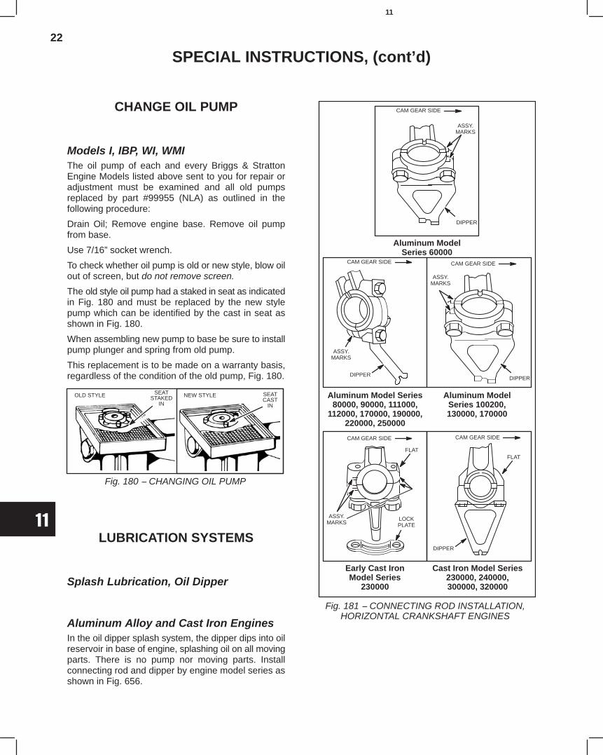
22
11
SPECIAL INSTRUCTIONS, (cont’d)
CHANGE OIL PUMP
Models I, IBP, WI, WMIThe oil pump of each and every Briggs & StrattonEngine Models listed above sent to you for repair oradjustment must be examined and all old pumpsreplaced by part #99955 (NLA) as outlined in thefollowing procedure:
Drain Oil; Remove engine base. Remove oil pumpfrom base.
Use 7/16” socket wrench.
To check whether oil pump is old or new style, blow oilout of screen, but do not remove screen.
The old style oil pump had a staked in seat as indicatedin Fig. 180 and must be replaced by the new stylepump which can be identified by the cast in seat asshown in Fig. 180.
When assembling new pump to base be sure to installpump plunger and spring from old pump.
This replacement is to be made on a warranty basis,regardless of the condition of the old pump, Fig. 180.
Fig. 180 − CHANGING OIL PUMP
OLD STYLE SEATSTAKED
IN
NEW STYLE SEATCAST
IN
LUBRICATION SYSTEMS
Splash Lubrication, Oil Dipper
Aluminum Alloy and Cast Iron EnginesIn the oil dipper splash system, the dipper dips into oilreservoir in base of engine, splashing oil on all movingparts. There is no pump nor moving parts. Installconnecting rod and dipper by engine model series asshown in Fig. 656.
Early Cast IronModel Series
230000
Aluminum ModelSeries 60000
Aluminum Model Series80000, 90000, 111000,
112000, 170000, 190000,220000, 250000
Aluminum ModelSeries 100200,130000, 170000
Cast Iron Model Series230000, 240000,300000, 320000
Fig. 181 − CONNECTING ROD INSTALLATION,HORIZONTAL CRANKSHAFT ENGINES
CAM GEAR SIDE
DIPPER
ASSY.MARKS
CAM GEAR SIDE CAM GEAR SIDE
ASSY.MARKS
DIPPERDIPPER
ASSY.MARKS
ASSY.MARKS
FLAT
LOCKPLATE
CAM GEAR SIDE CAM GEAR SIDE
FLAT
DIPPER
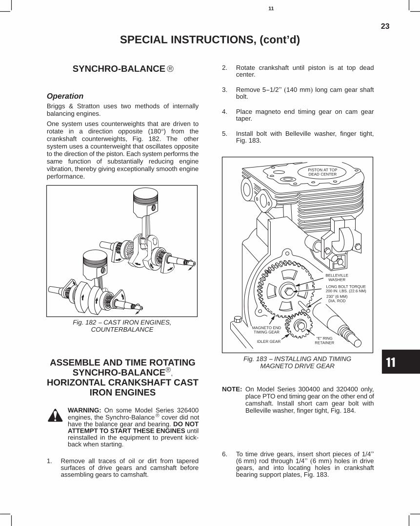
23
11
SPECIAL INSTRUCTIONS, (cont’d)
SYNCHRO-BALANCE
OperationBriggs & Stratton uses two methods of internallybalancing engines.
One system uses counterweights that are driven torotate in a direction opposite (180°) from thecrankshaft counterweights, Fig. 182. The othersystem uses a counterweight that oscillates oppositeto the direction of the piston. Each system performs thesame function of substantially reducing enginevibration, thereby giving exceptionally smooth engineperformance.
Fig. 182 − CAST IRON ENGINES,COUNTERBALANCE
ASSEMBLE AND TIME ROTATINGSYNCHRO-BALANCE,
HORIZONTAL CRANKSHAFT CASTIRON ENGINES
WARNING: On some Model Series 326400engines, the Synchro-Balance cover did nothave the balance gear and bearing. DO NOTATTEMPT TO START THESE ENGINES untilreinstalled in the equipment to prevent kick-back when starting.
1. Remove all traces of oil or dirt from taperedsurfaces of drive gears and camshaft beforeassembling gears to camshaft.
2. Rotate crankshaft until piston is at top deadcenter.
3. Remove 5−1/2" (140 mm) long cam gear shaftbolt.
4. Place magneto end timing gear on cam geartaper.
5. Install bolt with Belleville washer, finger tight,Fig. 183.
LONG BOLT TORQUE200 IN. LBS. (22.6 NM)
BELLEVILLEWASHER
“E” RINGRETAINERIDLER GEAR
MAGNETO ENDTIMING GEAR
PISTON AT TOPDEAD CENTER
230” (6 MM)DIA. ROD
Fig. 183 − INSTALLING AND TIMINGMAGNETO DRIVE GEAR
NOTE: On Model Series 300400 and 320400 only,place PTO end timing gear on the other end ofcamshaft. Install short cam gear bolt withBelleville washer, finger tight, Fig. 184.
6. To time drive gears, insert short pieces of 1/4"(6 mm) rod through 1/4" (6 mm) holes in drivegears, and into locating holes in crankshaftbearing support plates, Fig. 183.
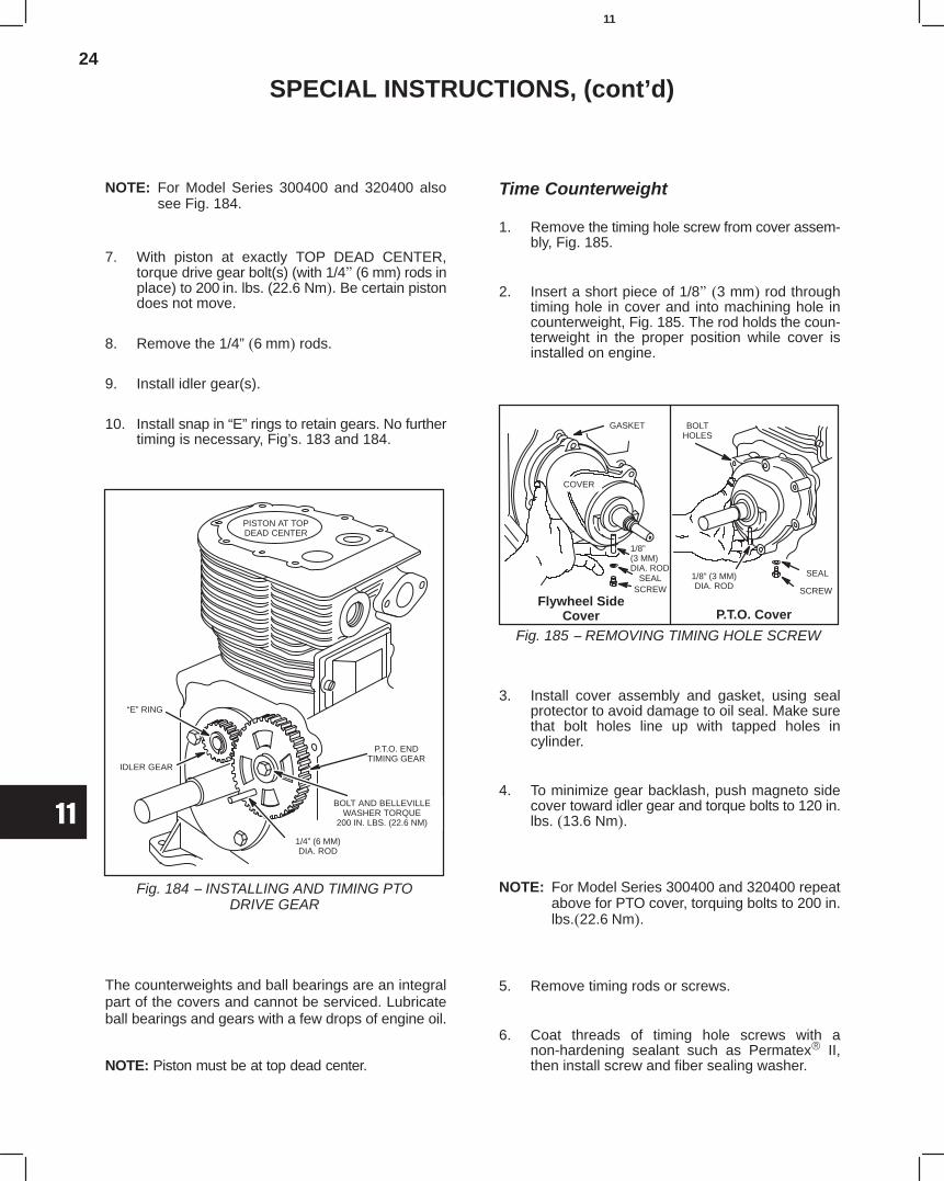
24
11
SPECIAL INSTRUCTIONS, (cont’d)
NOTE: For Model Series 300400 and 320400 alsosee Fig. 184.
7. With piston at exactly TOP DEAD CENTER,torque drive gear bolt(s) (with 1/4" (6 mm) rods inplace) to 200 in. lbs. (22.6 Nm). Be certain pistondoes not move.
8. Remove the 1/4” (6 mm) rods.
9. Install idler gear(s).
10. Install snap in “E” rings to retain gears. No furthertiming is necessary, Fig’s. 183 and 184.
P.T.O. ENDTIMING GEAR
PISTON AT TOPDEAD CENTER
IDLER GEAR
1/4” (6 MM)DIA. ROD
“E” RING
BOLT AND BELLEVILLEWASHER TORQUE
200 IN. LBS. (22.6 NM)
Fig. 184 − INSTALLING AND TIMING PTODRIVE GEAR
The counterweights and ball bearings are an integralpart of the covers and cannot be serviced. Lubricateball bearings and gears with a few drops of engine oil.
NOTE: Piston must be at top dead center.
Time Counterweight
1. Remove the timing hole screw from cover assem-bly, Fig. 185.
2. Insert a short piece of 1/8" (3 mm) rod throughtiming hole in cover and into machining hole incounterweight, Fig. 185. The rod holds the coun-terweight in the proper position while cover isinstalled on engine.
SCREW
SEAL
1/8”(3 MM)DIA. ROD
SEALSCREW
GASKET
COVER
1/8” (3 MM)DIA. ROD
Fig. 185 − REMOVING TIMING HOLE SCREW
Flywheel SideCover P.T.O. Cover
BOLTHOLES
3. Install cover assembly and gasket, using sealprotector to avoid damage to oil seal. Make surethat bolt holes line up with tapped holes incylinder.
4. To minimize gear backlash, push magneto sidecover toward idler gear and torque bolts to 120 in.lbs. (13.6 Nm).
NOTE: For Model Series 300400 and 320400 repeatabove for PTO cover, torquing bolts to 200 in.lbs.(22.6 Nm).
5. Remove timing rods or screws.
6. Coat threads of timing hole screws with anon-hardening sealant such as Permatex II,then install screw and fiber sealing washer.
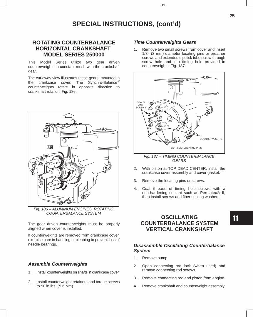
25
11
SPECIAL INSTRUCTIONS, (cont’d)
ROTATING COUNTERBALANCEHORIZONTAL CRANKSHAFT
MODEL SERIES 250000This Model Series utilize two gear drivencounterweights in constant mesh with the crankshaftgear.
The cut-away view illustrates these gears, mounted inthe crankcase cover. The Synchro-Balance
counterweights rotate in opposite direction tocrankshaft rotation, Fig. 186.
Fig. 186 − ALUMINUM ENGINES, ROTATINGCOUNTERBALANCE SYSTEM
The gear driven counterweights must be properlyaligned when cover is installed.
If counterweights are removed from crankcase cover,exercise care in handling or cleaning to prevent loss ofneedle bearings.
Assemble Counterweights
1. Install counterweights on shafts in crankcase cover.
2. Install counterweight retainers and torque screwsto 50 in.lbs. (5.6 Nm).
Time Counterweights Gears1. Remove two small screws from cover and insert
1/8" (3 mm) diameter locating pins or breatherscrews and extended dipstick tube screw throughscrew hole and into timing hole provided incounterweights, Fig. 187.
COUNTERWEIGHTS
1/8” (3 MM) LOCATING PINS
SEALSAND
SCREWS
Fig. 187 − TIMING COUNTERBALANCEGEARS
2. With piston at TOP DEAD CENTER, install thecrankcase cover assembly and cover gasket.
3. Remove the locating pins or screws.
4. Coat threads of timing hole screws with anon-hardening sealant such as Permatex II,then install screws and fiber sealing washers.
OSCILLATINGCOUNTERBALANCE SYSTEM
VERTICAL CRANKSHAFT
Disassemble Oscillating CounterbalanceSystem1. Remove sump.
2. Open connecting rod lock (when used) andremove connecting rod screws.
3. Remove connecting rod and piston from engine.
4. Remove crankshaft and counterweight assembly.
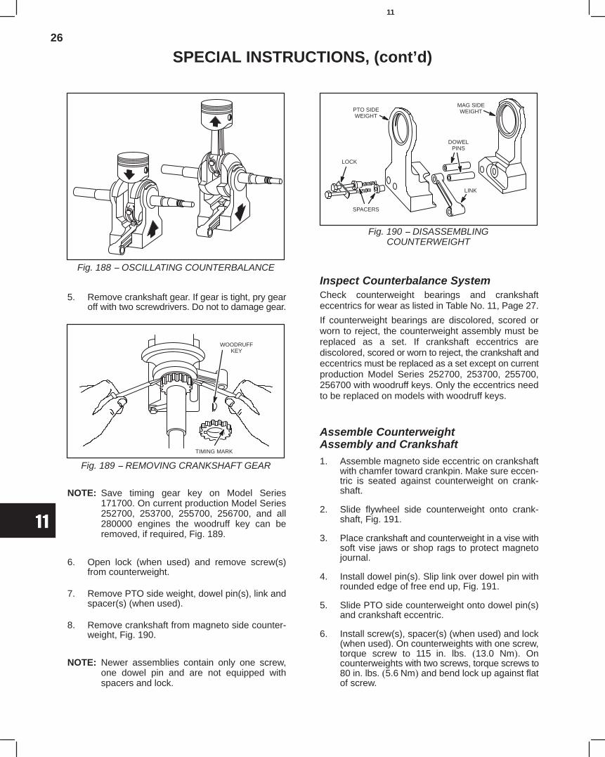
26
11
SPECIAL INSTRUCTIONS, (cont’d)
Fig. 188 − OSCILLATING COUNTERBALANCE
5. Remove crankshaft gear. If gear is tight, pry gearoff with two screwdrivers. Do not to damage gear.
TIMING MARK
Fig. 189 − REMOVING CRANKSHAFT GEAR
WOODRUFFKEY
NOTE: Save timing gear key on Model Series171700. On current production Model Series252700, 253700, 255700, 256700, and all280000 engines the woodruff key can beremoved, if required, Fig. 189.
6. Open lock (when used) and remove screw(s)from counterweight.
7. Remove PTO side weight, dowel pin(s), link andspacer(s) (when used).
8. Remove crankshaft from magneto side counter-weight, Fig. 190.
NOTE: Newer assemblies contain only one screw,one dowel pin and are not equipped withspacers and lock.
PTO SIDEWEIGHT
SPACERS
LOCK
DOWELPINS
LINK
MAG SIDEWEIGHT
Fig. 190 − DISASSEMBLINGCOUNTERWEIGHT
Inspect Counterbalance SystemCheck counterweight bearings and crankshafteccentrics for wear as listed in Table No. 11, Page 27.
If counterweight bearings are discolored, scored orworn to reject, the counterweight assembly must bereplaced as a set. If crankshaft eccentrics arediscolored, scored or worn to reject, the crankshaft andeccentrics must be replaced as a set except on currentproduction Model Series 252700, 253700, 255700,256700 with woodruff keys. Only the eccentrics needto be replaced on models with woodruff keys.
Assemble CounterweightAssembly and Crankshaft1. Assemble magneto side eccentric on crankshaft
with chamfer toward crankpin. Make sure eccen-tric is seated against counterweight on crank-shaft.
2. Slide flywheel side counterweight onto crank-shaft, Fig. 191.
3. Place crankshaft and counterweight in a vise withsoft vise jaws or shop rags to protect magnetojournal.
4. Install dowel pin(s). Slip link over dowel pin withrounded edge of free end up, Fig. 191.
5. Slide PTO side counterweight onto dowel pin(s)and crankshaft eccentric.
6. Install screw(s), spacer(s) (when used) and lock(when used). On counterweights with one screw,torque screw to 115 in. lbs. (13.0 Nm). Oncounterweights with two screws, torque screws to80 in. lbs. (5.6 Nm) and bend lock up against flatof screw.
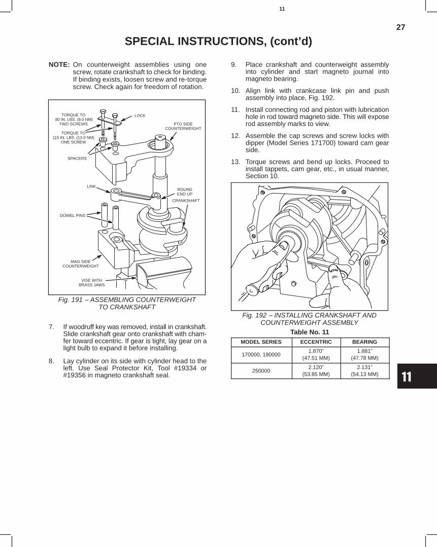
27
11
SPECIAL INSTRUCTIONS, (cont’d)
NOTE: On counterweight assemblies using onescrew, rotate crankshaft to check for binding.If binding exists, loosen screw and re-torquescrew. Check again for freedom of rotation.
VISE WITHBRASS JAWS
PTO SIDECOUNTERWEIGHT
DOWEL PINS
ROUNDEND UP
LINK
SPACERS
LOCKTORQUE TO 80 IN. LBS. (9.0 NM)
TWO SCREWS
TORQUE TO115 IN. LBS. (13.0 NM)
ONE SCREW
MAG SIDECOUNTERWEIGHT
Fig. 191 − ASSEMBLING COUNTERWEIGHTTO CRANKSHAFT
CRANKSHAFT
7. If woodruff key was removed, install in crankshaft.Slide crankshaft gear onto crankshaft with cham-fer toward eccentric. If gear is tight, lay gear on alight bulb to expand it before installing.
8. Lay cylinder on its side with cylinder head to theleft. Use Seal Protector Kit, Tool #19334 or#19356 in magneto crankshaft seal.
9. Place crankshaft and counterweight assemblyinto cylinder and start magneto journal intomagneto bearing.
10. Align link with crankcase link pin and pushassembly into place, Fig. 192.
11. Install connecting rod and piston with lubricationhole in rod toward magneto side. This will exposerod assembly marks to view.
12. Assemble the cap screws and screw locks withdipper (Model Series 171700) toward cam gearside.
13. Torque screws and bend up locks. Proceed toinstall tappets, cam gear, etc., in usual manner,Section 10.
Fig. 192 − INSTALLING CRANKSHAFT ANDCOUNTERWEIGHT ASSEMBLY
Table No. 11MODEL SERIES ECCENTRIC BEARING
170000, 1900001.870”
(47.51 MM)1.881”
(47.78 MM)
2500002.120”
(53.85 MM)2.131”
(54.13 MM)

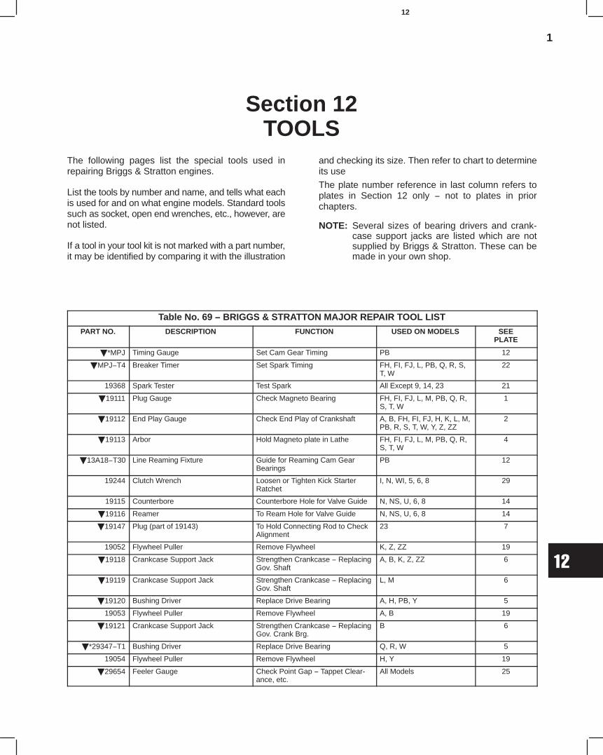
1
12
Section 12TOOLS
The following pages list the special tools used inrepairing Briggs & Stratton engines.
List the tools by number and name, and tells what eachis used for and on what engine models. Standard toolssuch as socket, open end wrenches, etc., however, arenot listed.
If a tool in your tool kit is not marked with a part number,it may be identified by comparing it with the illustration
and checking its size. Then refer to chart to determineits use
The plate number reference in last column refers toplates in Section 12 only − not to plates in priorchapters.
NOTE: Several sizes of bearing drivers and crank-case support jacks are listed which are notsupplied by Briggs & Stratton. These can bemade in your own shop.
TOOLS
Table No. 69 − BRIGGS & STRATTON MAJOR REPAIR TOOL LIST
PART NO. DESCRIPTION FUNCTION USED ON MODELS SEEPLATE
*MPJ Timing Gauge Set Cam Gear Timing PB 12
MPJ−T4 Breaker Timer Set Spark Timing FH, FI, FJ, L, PB, Q, R, S,T, W
22
19368 Spark Tester Test Spark All Except 9, 14, 23 21
19111 Plug Gauge Check Magneto Bearing FH, FI, FJ, L, M, PB, Q, R,S, T, W
1
19112 End Play Gauge Check End Play of Crankshaft A, B, FH, FI, FJ, H, K, L, M,PB, R, S, T, W, Y, Z, ZZ
2
19113 Arbor Hold Magneto plate in Lathe FH, FI, FJ, L, M, PB, Q, R,S, T, W
4
13A18−T30 Line Reaming Fixture Guide for Reaming Cam GearBearings
PB 12
19244 Clutch Wrench Loosen or Tighten Kick StarterRatchet
I, N, WI, 5, 6, 8 29
19115 Counterbore Counterbore Hole for Valve Guide N, NS, U, 6, 8 14
19116 Reamer To Ream Hole for Valve Guide N, NS, U, 6, 8 14
19147 Plug (part of 19143) To Hold Connecting Rod to CheckAlignment
23 7
19052 Flywheel Puller Remove Flywheel K, Z, ZZ 19
19118 Crankcase Support Jack Strengthen Crankcase − ReplacingGov. Shaft
A, B, K, Z, ZZ 6
19119 Crankcase Support Jack Strengthen Crankcase − ReplacingGov. Shaft
L, M 6
19120 Bushing Driver Replace Drive Bearing A, H, PB, Y 5
19053 Flywheel Puller Remove Flywheel A, B 19
19121 Crankcase Support Jack Strengthen Crankcase − ReplacingGov. Crank Brg.
B 6
*29347−T1 Bushing Driver Replace Drive Bearing Q, R, W 5
19054 Flywheel Puller Remove Flywheel H, Y 19
29654 Feeler Gauge Check Point Gap − Tappet Clear-ance, etc.
All Models 25
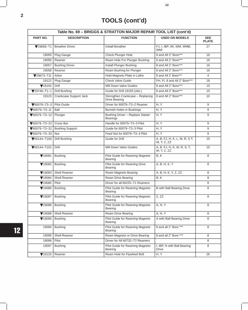
2
12
TOOLS (cont’d)
Table No. 69 − BRIGGS & STRATTON MAJOR REPAIR TOOL LIST (cont’d)
PART NO. DESCRIPTION FUNCTION USED ON MODELS SEEPLATE
29658−T1 Breather Driver Install Breather FJ, I, IBP, WI, WM, WMB,WMI
27
19055 Plug Gauge Check Plunger Hole 8 and All 2” Bore*** 16
19056 Reamer Ream Hole For Plunger Bushing 8 and All 2” Bore*** 16
19057 Bushing Driver Install Plunger Bushing 8 and All 2” Bore*** 16
19058 Reamer Ream Bushing for Plunger 8 and All 2” Bore*** 16
29673−T11 Arbor Hold Magneto Plate in Lathe 8 and All 2’ Bore*** 4
19122 Plug Gauge Check Valve Guide FH, FI, 8 and All 2” Bore*** 18
19155 Drill Mill Down Valve Guides 8 and All 2” Bore*** 15
29746−T1−1 Drill Bushing Guide for Drill 19155 (obs.) 8 and All 2” Bore*** 15
19123 Crankcase Support Jack Strengthen Crankcase − ReplacingDrive Bearing
8 and All 2” Bore*** 10
60079−T3−3 Pilot Guide Driver for 60079−T3−2 Reamer H, Y 9
60079−T3−11 Ball Burnish Holes in Bushings H, Y 9
60079−T3−12 Plunger Bushing Driver − Replace StarterBearings
H, Y 9
60079−T3−22 Cross Bar Handle for 60079−T3−3 Pilot H, Y 9
60079−T3−31 Bushing Support Guide for 60079−T3−3 Pilot H, Y 9
60079−T3−32 Nut Feed Nut for 60079−T3−3 Pilot H, Y 9
60144−T100 Drill Bushing Guide for Drill A, B, FJ, H, K, L, M, R, S T,W, Y, Z, ZZ
15
60144−T101 Drill Mill Down Valve Guides A, B, FJ, H, K, M, R, S, T,W, Y, Z, ZZ
15
19081 Bushing Pilot Guide for Reaming MagnetoBearing
B, K 8
19082 Bushing Pilot Guide for Reaming DriveBearing
A, B, H, K, Y 8
19083 Shell Reamer Ream Magneto Bearing A, B, H, K, Y, Z, ZZ 8
19084 Shell Reamer Ream Drive Bearing B, K 8
19085 Pilot Driver for all 60225−T1 Reamers 8
19086 Bushing Pilot Guide for Reaming MagnetoBearing
B with Ball Bearing Drive 8
19087 Bushing Pilot Guide for Reaming MagnetoBearing
Z, ZZ 8
19088 Bushing Pilot Guide for Reaming MagnetoBearing
A, H, Y 8
19089 Shell Reamer Ream Drive Bearing A, H, Y 8
19090 Bushing Pilot Guide for Reaming MagnetoBearing
A with Ball Bearing Drive 8
19094 Bushing Pilot Guide for Reaming MagnetoBearing
8 and all 2” Bore *** 8
19095 Shell Reamer Ream Magneto or Drive Bearing 8 and all 2” Bore *** 8
19096 Pilot Driver for All 60732−T2 Reamers 8
19097 Bushing Pilot Guide for Reaming MagnetoBearing
I, IBP, N with Ball BearingDrive
8
19125 Reamer Ream Hole for Flywheel Bolt H, Y 26
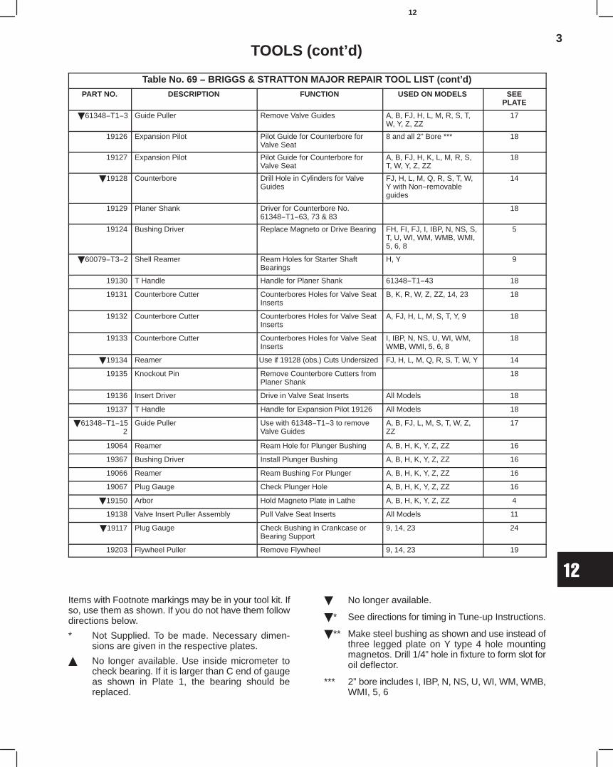
3
12
TOOLS (cont’d)
Table No. 69 − BRIGGS & STRATTON MAJOR REPAIR TOOL LIST (cont’d)
PART NO. DESCRIPTION FUNCTION USED ON MODELS SEEPLATE
61348−T1−3 Guide Puller Remove Valve Guides A, B, FJ, H, L, M, R, S, T,W, Y, Z, ZZ
17
19126 Expansion Pilot Pilot Guide for Counterbore forValve Seat
8 and all 2” Bore *** 18
19127 Expansion Pilot Pilot Guide for Counterbore forValve Seat
A, B, FJ, H, K, L, M, R, S,T, W, Y, Z, ZZ
18
19128 Counterbore Drill Hole in Cylinders for ValveGuides
FJ, H, L, M, Q, R, S, T, W,Y with Non−removableguides
14
19129 Planer Shank Driver for Counterbore No.61348−T1−63, 73 & 83
18
19124 Bushing Driver Replace Magneto or Drive Bearing FH, FI, FJ, I, IBP, N, NS, S,T, U, WI, WM, WMB, WMI,5, 6, 8
5
60079−T3−2 Shell Reamer Ream Holes for Starter ShaftBearings
H, Y 9
19130 T Handle Handle for Planer Shank 61348−T1−43 18
19131 Counterbore Cutter Counterbores Holes for Valve SeatInserts
B, K, R, W, Z, ZZ, 14, 23 18
19132 Counterbore Cutter Counterbores Holes for Valve SeatInserts
A, FJ, H, L, M, S, T, Y, 9 18
19133 Counterbore Cutter Counterbores Holes for Valve SeatInserts
I, IBP, N, NS, U, WI, WM,WMB, WMI, 5, 6, 8
18
19134 Reamer Use if 19128 (obs.) Cuts Undersized FJ, H, L, M, Q, R, S, T, W, Y 14
19135 Knockout Pin Remove Counterbore Cutters fromPlaner Shank
18
19136 Insert Driver Drive in Valve Seat Inserts All Models 18
19137 T Handle Handle for Expansion Pilot 19126 All Models 18
61348−T1−152
Guide Puller Use with 61348−T1−3 to removeValve Guides
A, B, FJ, L, M, S, T, W, Z,ZZ
17
19064 Reamer Ream Hole for Plunger Bushing A, B, H, K, Y, Z, ZZ 16
19367 Bushing Driver Install Plunger Bushing A, B, H, K, Y, Z, ZZ 16
19066 Reamer Ream Bushing For Plunger A, B, H, K, Y, Z, ZZ 16
19067 Plug Gauge Check Plunger Hole A, B, H, K, Y, Z, ZZ 16
19150 Arbor Hold Magneto Plate in Lathe A, B, H, K, Y, Z, ZZ 4
19138 Valve Insert Puller Assembly Pull Valve Seat Inserts All Models 11
19117 Plug Gauge Check Bushing in Crankcase orBearing Support
9, 14, 23 24
19203 Flywheel Puller Remove Flywheel 9, 14, 23 19
Items with Footnote markings may be in your tool kit. Ifso, use them as shown. If you do not have them followdirections below.
* Not Supplied. To be made. Necessary dimen-sions are given in the respective plates.
No longer available. Use inside micrometer tocheck bearing. If it is larger than C end of gaugeas shown in Plate 1, the bearing should bereplaced.
No longer available.
* See directions for timing in Tune-up Instructions.
** Make steel bushing as shown and use instead ofthree legged plate on Y type 4 hole mountingmagnetos. Drill 1/4” hole in fixture to form slot foroil deflector.
*** 2” bore includes I, IBP, N, NS, U, WI, WM, WMB,WMI, 5, 6

4
12
TOOLS (cont’d)
291661 TOOL KIT(CONSISTS OF THE FOLLOWING TOOLS)
PART NO. DESCRIPTION MODELS USED ON
19368 Spark Tester All Models
19052 Wheel Puller K, Z, ZZ
19053 Wheel Puller A, B
19054 Wheel Puller H, Y
29654 Feeler Gauge All Models
29658−T1 (obs.) Breather Driver FJ, I, IBP, WI, WM, WMB, WMI
19055 Plug Gauge 8 and all 2” bore*
19056 Contact Plunger Hole Reamer 8 and all 2” bore*
19057 Bushing Driver 8 and all 2” bore
19058 Contact Plunger Bushing Reamer 8 and all 2” bore*
19059 (obs.) Flywheel Holder 8 and all 2” bore*
19060 Ignition Wrench (2 in kit) A, B, H, K, Y, Z, ZZ
63821 (obs.) Allen Wrench A, 8 and all 2” bore*
19061 Screw Driver A, 8, 9 and all 2” bore*
19062 Screw Driver B, K, ZZ, 14, 23
19063 Spring Compressor All except 2” bore and 8*
69751−T1 (obs.) Breather Driver A, B, H, K, L, M Q, R, S, T, W, Y, Z, ZZ
19064 Contact Plunger Hole Reamer A, B, H, K, Y, Z, ZZ
19274 Bushing Driver A, B, H, K, Y, Z, ZZ
19066 Contact Plunger Bushing Reamer A, B, H, K, Y, Z, ZZ
19067 Plug Gauge A, B, H, K, Y, Z, ZZ
19203 Wheel Puller 9, 14, 23
19081 (obs.) Bushing B, K
19082 (obs.) Bushing A, B, H, K, Y
19083 (obs.) Shell Reamer A, B, H, K, Y, Z, ZZ
19084 (obs.) Shell Reamer B. K
19085 (obs.) Pilot
19086 (obs.) Bushing B with ball bearing drive
19088 (obs.) Bushing A, H, Y
19089 (obs.) Shell Reamer A, H, Y
19090 (obs.) Bushing A with ball bearing drive
19094 Bushing 8 and 2” bore*
19095 Shell Reamer 8 and 2” bore*
19096 Pilot
19097 Bushing 8 and all 2” bore with ball bearing drive
19098 (obs.) Bearing Plug Gauge 8 and all 2” bore*
19091 (obs.) Bearing Plug Gauge A, H, Y
19092 (obs.) Bearing Plug Gauge B, K
19093 (obs.) Bearing Plug Gauge A, B, H, K, Y, Z, ZZ
* 2” bore includes Models I, IBP, N, NS, U, WI, WM, WMB, WMI, 5, 6
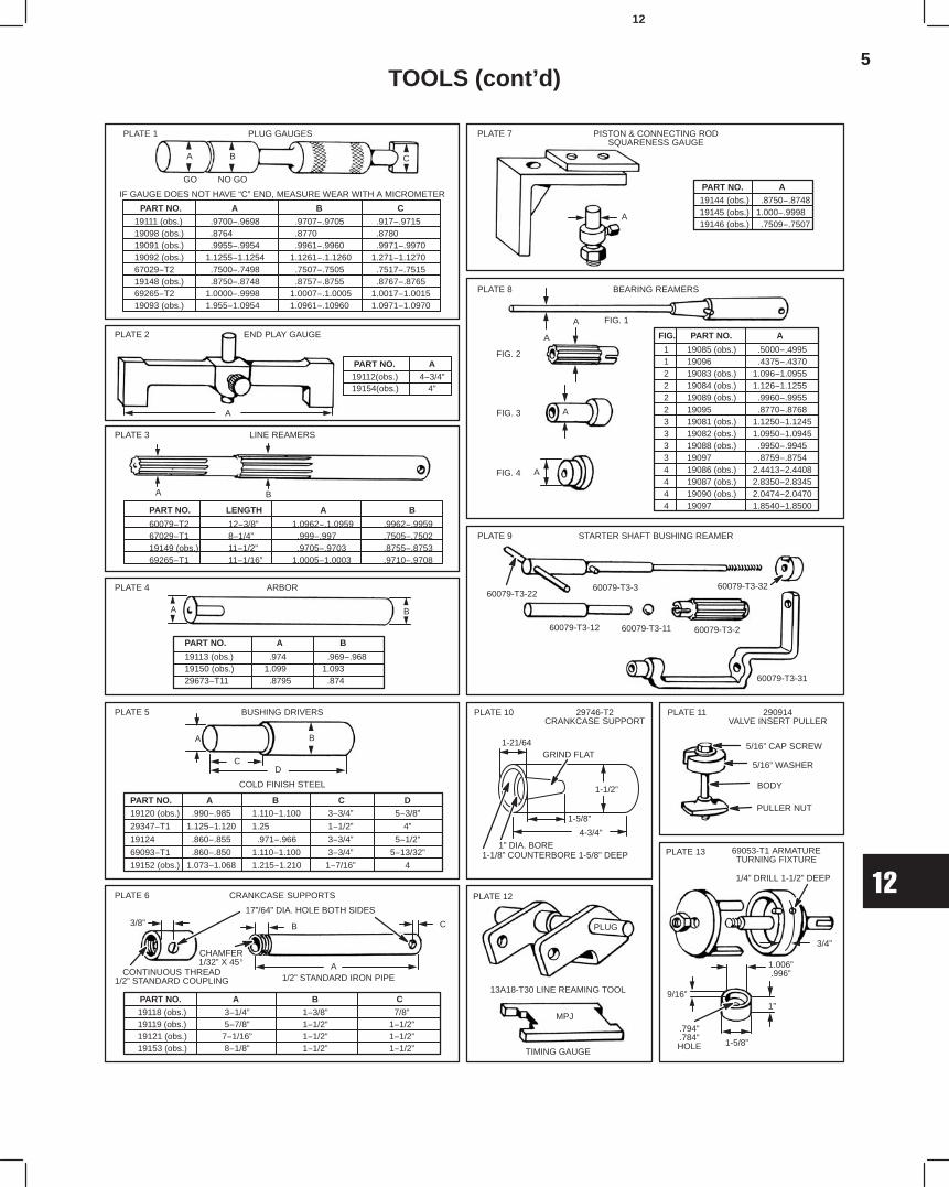
5
12
TOOLS (cont’d)
PART NO. A B C19118 (obs.) 3−1/4” 1−3/8” 7/8”19119 (obs.) 5−7/8” 1−1/2” 1−1/2”19121 (obs.) 7−1/16” 1−1/2” 1−1/2”19153 (obs.) 8−1/8” 1−1/2” 1−1/2”
FIG. PART NO. A
1 19085 (obs.) .5000−.49951 19096 .4375−.43702 19083 (obs.) 1.096−1.09552 19084 (obs.) 1.126−1.12552 19089 (obs.) .9960−.99552 19095 .8770−.87683 19081 (obs.) 1.1250−1.12453 19082 (obs.) 1.0950−1.09453 19088 (obs.) .9950−.99453 19097 .8759−.87544 19086 (obs.) 2.4413−2.44084 19087 (obs.) 2.8350−2.83454 19090 (obs.) 2.0474−2.04704 19097 1.8540−1.8500
PART NO. A B C
19111 (obs.) .9700−.9698 .9707−.9705 .917−.971519098 (obs.) .8764 .8770 .878019091 (obs.) .9955−.9954 .9961−.9960 .9971−.997019092 (obs.) 1.1255−1.1254 1.1261−.1.1260 1.271−1.127067029−T2 .7500−.7498 .7507−.7505 .7517−.751519148 (obs.) .8750−.8748 .8757−.8755 .8767−.876569265−T2 1.0000−.9998 1.0007−.1.0005 1.0017−1.001519093 (obs.) 1.955−1.0954 1.0961−.10960 1.0971−1.0970
PART NO. A19112(obs.) 4−3/4”19154(obs.) 4”
PART NO. LENGTH A B
60079−T2 12−3/8” 1.0962−.1.0959 .9962−.995967029−T1 8−1/4” .999−.997 .7505−.750219149 (obs.) 11−1/2” .9705−.9703 .8755−.875369265−T1 11−1/16” 1.0005−1.0003 .9710−.9708
PART NO. A B
19113 (obs.) .974 .969−.96819150 (obs.) 1.099 1.09329673−T11 .8795 .874
PART NO. A B C D19120 (obs.) .990−.985 1.110−1.100 3−3/4” 5−3/8”
29347−T1 1.125−1.120 1.25 1−1/2” 4”
19124 .860−.855 .971−.966 3−3/4” 5−1/2”
69093−T1 .860−.850 1.110−1.100 3−3/4” 5−13/32”
19152 (obs.) 1.073−1.068 1.215−1.210 1−7/16” 4
PART NO. A19144 (obs.) .8750−.874819145 (obs.) 1.000−.999819146 (obs.) .7509−.7507
A B C
PLUG GAUGES
IF GAUGE DOES NOT HAVE “C” END, MEASURE WEAR WITH A MICROMETER
GO NO GO
PLATE 1
END PLAY GAUGEPLATE 2
A
LINE REAMERSPLATE 3
A B
ARBORPLATE 4
A B
A B
CD
BUSHING DRIVERSPLATE 5
COLD FINISH STEEL
CRANKCASE SUPPORTSPLATE 6
CONTINUOUS THREAD1/2” STANDARD COUPLING
CHAMFER1/32” X 45
3/8” B C
A1/2” STANDARD IRON PIPE
17”/64” DIA. HOLE BOTH SIDES
PISTON & CONNECTING RODSQUARENESS GAUGE
PLATE 7
A
BEARING REAMERSPLATE 8
FIG. 1
FIG. 2
FIG. 3
FIG. 4
A
A
A
A
STARTER SHAFT BUSHING REAMERPLATE 9
60079-T3-2260079-T3-3 60079-T3-32
60079-T3-12 60079-T3-11 60079-T3-2
60079-T3-31
29746-T2CRANKCASE SUPPORT
PLATE 10
GRIND FLAT1-21/64
1-1/2”
1-5/8”
4-3/4”1” DIA. BORE
1-1/8” COUNTERBORE 1-5/8” DEEP
290914VALVE INSERT PULLER
PLATE 11
5/16” CAP SCREW
5/16” WASHER
BODY
PULLER NUT
13A18-T30 LINE REAMING TOOL
PLATE 12
TIMING GAUGE
69053-T1 ARMATURETURNING FIXTURE
PLATE 13
PLUG
MPJ1”
1/4” DRILL 1-1/2” DEEP
3/4”
1.006”.996”
1-5/8”
9/16”
.794”
.784”HOLE
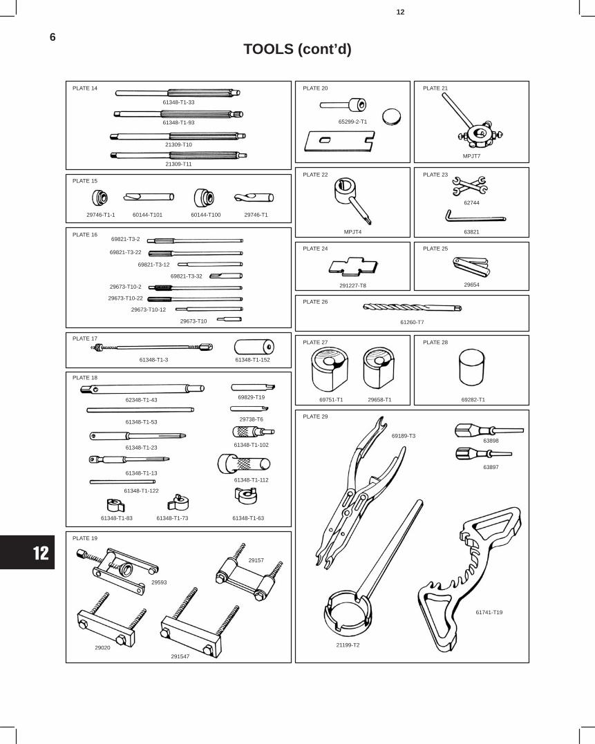
6
12
TOOLS (cont’d)
PLATE 14
61348-T1-33
61348-T1-93
21309-T10
21309-T11
PLATE 15
29746-T1-1 60144-T101 60144-T100 29746-T1
69821-T3-2
69821-T3-22
69821-T3-12
69821-T3-32
29673-T10-2
29673-T10-22
29673-T10-12
29673-T10
PLATE 16
PLATE 17
61348-T1-3 61348-T1-152
62348-T1-43
61348-T1-53
61348-T1-23
61348-T1-13
61348-T1-122
61348-T1-83 61348-T1-73 61348-T1-63
69829-T19
29738-T6
61348-T1-102
61348-T1-112
29593
29157
29020
291547
PLATE 18
PLATE 19
PLATE 20 PLATE 21
PLATE 22 PLATE 23
PLATE 24 PLATE 25
PLATE 26
PLATE 27 PLATE 28
PLATE 29
65299-2-T1
MPJT7
MPJT4
62744
63821
291227-T8 29654
61260-T7
69751-T1 29658-T1 69282-T1
69189-T363898
63897
21199-T2
61741-T19
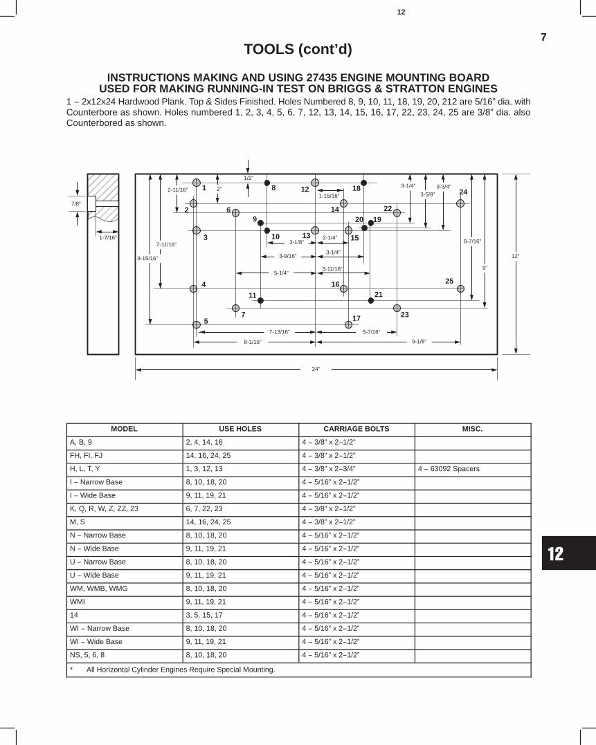
7
12
TOOLS (cont’d)
INSTRUCTIONS MAKING AND USING 27435 ENGINE MOUNTING BOARDUSED FOR MAKING RUNNING-IN TEST ON BRIGGS & STRATTON ENGINES
1 − 2x12x24 Hardwood Plank. Top & Sides Finished. Holes Numbered 8, 9, 10, 11, 18, 19, 20, 212 are 5/16” dia. withCounterbore as shown. Holes numbered 1, 2, 3, 4, 5, 6, 7, 12, 13, 14, 15, 16, 17, 22, 23, 24, 25 are 3/8” dia. alsoCounterbored as shown.
ÉÉÉÉÉÉÉÉÉÉÉÉ
7/8”
1-7/16”
9-15/16”
7-11/16”
2-11/16” 2”
1/2”
8-1/16”
7-13/16”
5-1/4”
3-9/16”
3-1/8”
1-15/16”
2-1/4”
3-1/4”
3-11/16”
5-7/16”
9-1/8”
24”
3-1/4”
3-5/8”3-3/4”
8-7/16”
9”
12”
25
23
21
24
22
20 19
15
18
14
128
1310
96
3
4
7
11
16
175
1
2
MODEL USE HOLES CARRIAGE BOLTS MISC.
A, B, 9 2, 4, 14, 16 4 − 3/8” x 2−1/2”
FH, FI, FJ 14, 16, 24, 25 4 − 3/8” x 2−1/2”
H, L, T, Y 1, 3, 12, 13 4 − 3/8” x 2−3/4” 4 − 63092 Spacers
I − Narrow Base 8, 10, 18, 20 4 − 5/16” x 2−1/2”
I − Wide Base 9, 11, 19, 21 4 − 5/16” x 2−1/2”
K, Q, R, W, Z, ZZ, 23 6, 7, 22, 23 4 − 3/8” x 2−1/2”
M, S 14, 16, 24, 25 4 − 3/8” x 2−1/2”
N − Narrow Base 8, 10, 18, 20 4 − 5/16” x 2−1/2”
N − Wide Base 9, 11, 19, 21 4 − 5/16” x 2−1/2”
U − Narrow Base 8, 10, 18, 20 4 − 5/16” x 2−1/2”
U − Wide Base 9, 11, 19, 21 4 − 5/16” x 2−1/2”
WM, WMB, WMG 8, 10, 18, 20 4 − 5/16” x 2−1/2”
WMI 9, 11, 19, 21 4 − 5/16” x 2−1/2”
14 3, 5, 15, 17 4 − 5/16” x 2−1/2”
WI − Narrow Base 8, 10, 18, 20 4 − 5/16” x 2−1/2”
WI − Wide Base 9, 11, 19, 21 4 − 5/16” x 2−1/2”
NS, 5, 6, 8 8, 10, 18, 20 4 − 5/16” x 2−1/2”
* All Horizontal Cylinder Engines Require Special Mounting.
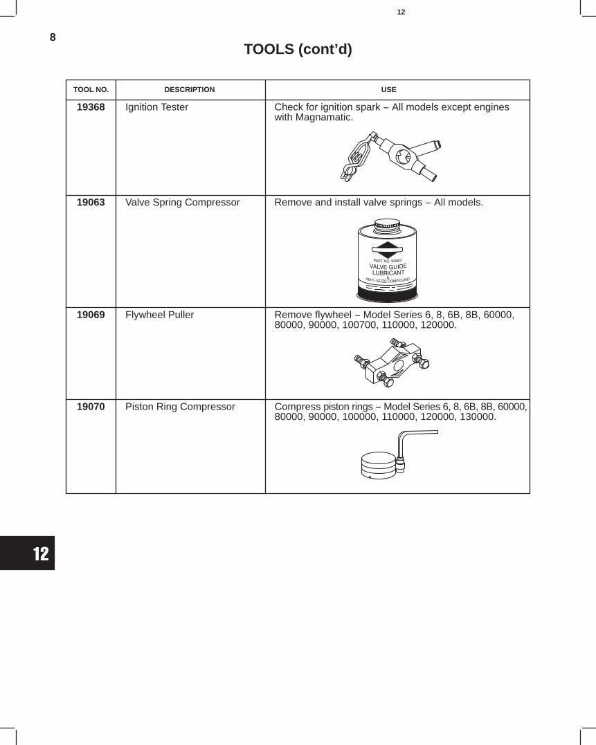
8
12
TOOLS (cont’d)
19368 Ignition Tester Check for ignition spark − All models except engineswith Magnamatic.
19063 Valve Spring Compressor Remove and install valve springs − All models.
19069 Flywheel Puller Remove flywheel − Model Series 6, 8, 6B, 8B, 60000,80000, 90000, 100700, 110000, 120000.
19070 Piston Ring Compressor Compress piston rings − Model Series 6, 8, 6B, 8B, 60000,80000, 90000, 100000, 110000, 120000, 130000.
TOOL NO. DESCRIPTION USE
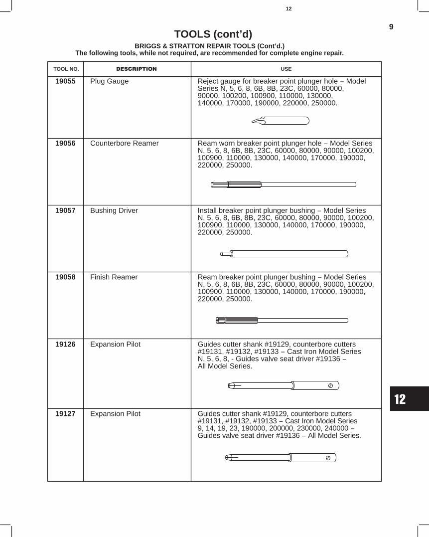
9
12
BRIGGS & STRATTON REPAIR TOOLS (Cont’d.)The following tools, while not required, are recommended for complete engine repair.
TOOLS (cont’d)
TOOL NO. DESCRIPTION USE
19055 Plug Gauge Reject gauge for breaker point plunger hole − ModelSeries N, 5, 6, 8, 6B, 8B, 23C, 60000, 80000,90000, 100200, 100900, 110000, 130000,140000, 170000, 190000, 220000, 250000.
19056 Counterbore Reamer Ream worn breaker point plunger hole − Model SeriesN, 5, 6, 8, 6B, 8B, 23C, 60000, 80000, 90000, 100200,100900, 110000, 130000, 140000, 170000, 190000,220000, 250000.
19057 Bushing Driver Install breaker point plunger bushing − Model SeriesN, 5, 6, 8, 6B, 8B, 23C, 60000, 80000, 90000, 100200,100900, 110000, 130000, 140000, 170000, 190000,220000, 250000.
19058 Finish Reamer Ream breaker point plunger bushing − Model SeriesN, 5, 6, 8, 6B, 8B, 23C, 60000, 80000, 90000, 100200,100900, 110000, 130000, 140000, 170000, 190000,220000, 250000.
19126 Expansion Pilot Guides cutter shank #19129, counterbore cutters#19131, #19132, #19133 − Cast Iron Model SeriesN, 5, 6, 8, - Guides valve seat driver #19136 −All Model Series.
19127 Expansion Pilot Guides cutter shank #19129, counterbore cutters#19131, #19132, #19133 − Cast Iron Model Series9, 14, 19, 23, 190000, 200000, 230000, 240000 −Guides valve seat driver #19136 − All Model Series.