Embed Size (px)
Citation preview
CoPTTM 4th Edition
Briefing for
Traffic control devices manual
Part 8 CoPTTM
Summary of amendments

Summary of amendments NZ Transport Agency
Traffic control devices manual part 8 CoPTTM – May 2013 1
Briefing Session Notes
Overview (highlights) � CoPTTM now section 8 of TCD manual
� Reinstated notification of changes
� LRS now in CoPTTM
� Update notes & technical notes included
� 4th Edition available electronically and in print
� Electronic version (PDFs) open with menu for browsing
� Print version – set of wire bound sections
� A5 size L1 TTM handbook
� Some sections renamed, some new sections
Section Name
Section A Introduction and general
Section B Equipment
Section C Static operations
Section D Mobile operations
Section E Standard forms and descriptions Previously section H appendices
Section F Level 1 example layouts Previously section E
Section G Level 2 example layouts Previously section F
Section H Level 3 example layouts Previously section G
Section I Special activities New section
Section J Level 1 Field book New section
� Changes to TMP (short and full forms)
� Barrier/barricade and fence have been updated
� Added TSL decision matrix
� Updated VMS and AWVMS
� TMA and LAS requirements included
� New sign numbers (TCD Rule change)
� Changes to LV and L1 layout distances at 50 and 60km/h
� On level 1 roads, RCA can permit:
o use of short TMP form (simple activities)
o traffic management diagrams (TMDs) to be used in a TMP
o STMS self approval of selected TMPs
� Other RCA decisions for level 1 roads:
o Extend any clear sight distances
o Where no LV roads have been designated, the RCA can select level 1 roads for ‘single inspector’ inspections
o Decide when level 2/3 sign sizes are required on level 1 multilane roads
� RCA will notify these decisions
Summary of amendments NZ Transport Agency
Traffic control devices manual part 8 CoPTTM – May 2013 2
� LV table is still there for those who use it
� The new level 1 layout distances table also includes the level LV distances as well
� The level 2 layout distances table now has 90km/h catered for
TMA and LAS
� Now mandatory for:
o level 2 and level 3 state highways (since 1 July 2010)
o All level 3 highways by 1 July 2012
� Optional for other RCAs
� Must comply with:
o NCHRP 350 test level 2
o weights of support vehicle
Rear panels
� Required for all horizontal arrow boards 1 July 2012 AWVMS
� The new AWVMS may replace the TMA tail pilot vehicle
� Using an AWVMS is optional for most RCAs
Sign stands for Level 2/3
� Still under review
� No effective date until resolved Approval of temporary speed limits
� There are new forms for short and full TMP
� The temporary speed limit (TSL) approval is now on the TMP
� Includes when, where and what TSL is to be applied
On-site record
� Important to fill in on-site record as speed setting rule states that when TSL signs are installed the speed limit applies
Audit
� New audit form -full and short audit (similar to checklist)

Summary of amendments NZ Transport Agency
Traffic control devices manual part 8 CoPTTM – May 2013 3
Section A
A4 Levels of temporary traffic management (TTM)
Extract from CoPTTM
There are four primary levels of road:
• Low volume (LV) For level LV, the following subcategory can also be designated for roads that have particularly low volumes of traffic:
o LV low-risk.
• Level 1. • Level 2. • Level 3 .
A5.3 Road controlling authority
Inserted LRS style authorisation if chosen by RCA
Extract from CoPTTM
For level LV and level 1 roads (non-state highway)
The RCA is responsible for:
• deciding which roads can use a generic traffic management diagram instead of a site-specific traffic management diagram as part of the TMP
• deciding whether TMP approvals will be delegated to selected STMS
• designating the minimum clear sight distance (CSD) if requiring more than 75m CSD on roads with a permanent speed of less than 55km/h
• identifying roads suitable for inspection activities to be completed by unaccompanied inspectors
• deciding whether level 2/3 sign sizes are required on selected multilane roads.
A5.5 Traffic management coordinator
TMC responsibilities have been expanded and are now similar to the engineer responsibilities
A5.8.4 Responsibilities of STMS on level LV and lev el 1 roads
The requirements have changed for travel time of STMS from each unattended worksite
Extract from CoPTTM
During the period of delegation to a TC or for unattended worksites the STMS must be within the following requirements:
Level of road Attended worksite delegated to a TC Unattended worksite
Level 1 30 minutes travel time of each worksite 60 minutes travel time of each worksite
Level LV 60 minutes travel time of each worksite 120 minutes travel time of each worksite
The STMS must limit the number of unattended worksites they are responsible for subject to their ability to satisfactorily perform all their duties to the required standards at all times.

Summary of amendments NZ Transport Agency
Traffic control devices manual part 8 CoPTTM – May 2013 4
A5.8.5 Responsibilities of STMS on level 2 & 3 road s
When the level 2/3 STMS must be onsite
• The STMS must be present at an attended worksite at all times except during a drive through when the STMS may need to leave the worksite to gain access to the front of the worksite. In this case the STMS may be away from the worksite for up to 30 minutes.
Exceptions to this rule are as follows:
• An STMS is permitted to control up to four attended shoulder closure worksites on level 2 and level 3 roads at any one time subject to the following:
o an STMS remains within 30 minutes of all worksites
o a person with a minimum qualification of STMS-NP is present and takes charge of TTM at each attended worksite
o that STMS-NP must have been briefed by the STMS and the briefing documented
o the STMS must be present for the set up, alteration and removal for each of the worksites.
Mobile operations on level 2 roads
• On level 2 roads where all activity is at least two metres clear of the edgeline, an STMS-NP may take the role of an STMS and set up, maintain, alter and remove TTM under the following conditions:
o the STMS must brief the STMS-NP in charge of the operation on the TTM requirements
o all the above actions must be documented by the STMS.
A5.9 Traffic controller
TC responsibilities now listed separately
Summary of amendments NZ Transport Agency
Traffic control devices manual part 8 CoPTTM – May 2013 5
A6.4 Certification and registration
Updated training process and clarified ROPE for Level 2/3 STMS
Requalification via a ROPE is a privilege - not a right
Extract from CoPTTM
Level 2/3 STMS
This qualification is tied to the time frame for the STMS-NP. They will lapse together and the STMS-NP must first be renewed as above.
In addition the applicant is required to either:
• resit a practical field assessment, or
• submit a recognition of prior experience (ROPE) form to the NZTA’s Senior Traffic and Safety Engineer (CoPTTM).
ROPE
• This form must contain the details of six closures completed while the practicing STMS held their qualification.
• The six closures must be carried out in the nine months preceding submission of the ROPE application
Non-conformance
Applicants who have received a non-conformance, or who have an unsatisfactory report may not be considered for ROPE. However if a non-conformance report is followed by a 12 month period of satisfactory performance the ROPE may still be allowed
A7 Traffic management plans
Revised application and approvals procedure to allow for STMS self-approval of TMP if permitted by the RCA
Extract from CoPTTM
TMP submitted for approval (or if delegated authority, an STMS approves TMP)
An STMS submits TMP to RCA for approval.
For selected level LV and level 1 roads (non-state highways) an STMS can approve the TMP without submitting it to the RCA if the:
• STMS has been delegated authority to approve TMPs by the RCA, and
• situation is one where TMC approval is not required by the RCA. Refer to subsection A7.2.1 STMS-delegated authority – situations for TMC approval.
For a detailed list of each RCA’s requirements refer to the NZTA’s website.
Revised application and approvals procedure to allow for short and full TMPs (forms in Section E)
Extract from CoPTTM
Type of form When to use
TMP – Short form Complete short form if simple activity and the RCA allows use of the form
TMP – Full form Use full form for activities involving a number of phases and/or delays (eg resealing, shoulder widening, road reconstruction)

Summary of amendments NZ Transport Agency
Traffic control devices manual part 8 CoPTTM – May 2013 6
Revised application and approvals procedure to allow for recording hazard identification, set-up, maintenance and removal of the worksite
Extract from CoPTTM
Once TMP is approved the worksite can be set up following requirements in section C and/or section D.
Complete hazard identification before setting up the worksite and put in place any mitigation steps required.
Record the set-up, maintenance and removal of the worksite on the CoPTTM on-site record (refer to section E, appendix A) or a company site safety checklist provided it includes the following information:
• details of the STMS who is in charge of the worksite (name, qualification, ID and expiry date of qualification)
• if worksite delegated to a TC (level 1) or STMS-NP (only on limited level 2 worksites), details of the TC/STMS-NP who is in charge of the worksite (name, qualification, ID and expiry date of qualification)
• the worksite monitoring including:
o site set-up
o two-hourly monitoring
o site removal
• details of any TSLs installed:
o date installed
o time installed
o placement (route position or street numbers)
o length of TSL (in metres)
o date removed
o time removed.
Record all changes to the TSL (change of speed or change of location of TSL).
Level 1 – STMS delegated authority (situations for TMC approval)
If the STMS has been delegated authority to approve TMPs on selected level LV and level 1 roads (non-state highways) they still must submit TMPs to the TMC for approval in the higher risk situations.
Each RCA can declare its own situations but the common ones are where:
Extract from CoPTTM
STMS-delegated authority - situations for TMC approval
• approval has been requested by the RCA during the planning process for a particular worksite or collection of worksites
• there is no traffic management diagram in the level LV and level 1 example plans that represents the worksite
• a road needs to be closed or traffic delays for more than five minutes at any one time during the day, or for a cumulative period of 30 minutes in any one hour period, except where otherwise specified by the RCA
• a footpath will be closed and users will have to enter/cross a live lane
• a cycle lane will be closed
• a pedestrian crossing or traffic signal installation is affected
• restricted parking, bus stops, loading zones and/or taxi stands will be affected
• portable traffic signals are to be used
• a lane closure is required at an intersection
• signs need to be placed on a flush median
• traffic moving in one direction is split around a closure
Summary of amendments NZ Transport Agency
Traffic control devices manual part 8 CoPTTM – May 2013 7
• mobile operations are on roads with posted speed limit exceeding 50km/h (except for grading operations)
• the activity is an event
• other situation/s as may be stipulated by the RCA.
Level 1 – Copy of TMP kept for one year
Extract from CoPTTM
For selected level LV and level 1 roads, if the TMP has been approved by the STMS under delegated authority, a copy of the TMP must be kept for one year.
Engineering exception decisions
There has been a change to the way EEDs are written
Extract from CoPTTM
The EED statement must describe:
• What the problem is:
a. Describe the road environment constraint.
b. State CoPTTM requirements for the proposed activity.
• Why CoPTTM-compliant TTM should not be installed.
• How will safety be ensured.
Forwarding Generic EEDs to NZTA
Extract from CoPTTM
All NZTA offices or their consultants must send a copy of all generic EEDs and the relevant plan for approval to the:
Senior Traffic and Safety Engineer (CoPTTM) NZ Transport Agency National Office Private Bag 6995 Wellington 6141 Phone: +64 4 894 6355 Email: [email protected]
RCA staff and their representatives may forward any generic EEDs to the above address for information and/or feedback if appropriate.
Using GTMPs
Extract from CoPTTM
The GTMPs may not be appropriate for every situation and it is the responsibility of the contractor, RCA and the engineer to check for this.
Notifying the TMC
Prior to using the GTMP the TMC must be notified of the GTMP number, the diagram(s) being used, the location and the date and time of the works to be undertaken.
The TMC may stipulate the method and extent of notification.
Actions on site
Each time a GTMP is used the following actions must be completed:
• Check that the diagram used is appropriate for the site – Refer section E, appendix A for the checking process for generic TMPs
• Complete the onsite record - Refer section E, appendix A.
Summary of amendments NZ Transport Agency
Traffic control devices manual part 8 CoPTTM – May 2013 8
A8 TTM audit procedures
New section which includes introduction to audit procedures
Refer to section E, appendix C: TTM Audit Methodology for a full description of the audit methodology and actions to take after the audit
Short and full audit (the forms are included in Section E)
Extract from CoPTTM
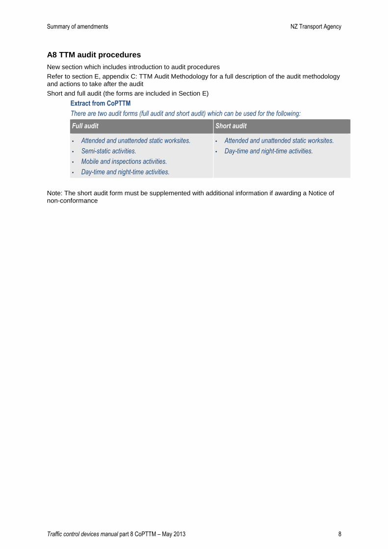
There are two audit forms (full audit and short audit) which can be used for the following:
Full audit Short audit
• Attended and unattended static worksites.
• Semi-static activities.
• Mobile and inspections activities.
• Day-time and night-time activities.
• Attended and unattended static worksites.
• Day-time and night-time activities.
Note: The short audit form must be supplemented with additional information if awarding a Notice of non-conformance

Summary of amendments NZ Transport Agency
Traffic control devices manual part 8 CoPTTM – May 2013 9
Section B
B1 Signs
New size for L1 supplementary plate. Was 950mm. Now 900mm to suit manufacture
Note: Old size is still valid
900mm
Changes to TCD rule has resulted in new sign numbers. The old numbers are still shown.
Extract from CoPTTM
Sign name Sign
reference
Old sign
referenc
e
Illustration Requirements for use
Road works
Level LV and
level 1
T1A TW - 1A
This sign is erected at all attended worksites. The sign
is also used at unattended worksites where there are
hazards within 5m of the edgeline.
An authorised supplementary sign may be used.
Road works
Level 2 and 3
T1B TW-1B
Road works
NEW SEAL
TR31 TW - 1.2
This supplementary plate is used with a T1A/B sign to
indicate sealing operations and a newly sealed
surface while it is susceptible to damage by motor
traffic.
It is used with a T1A/B advance warning sign.
Must use two numbers (1 for major sign, 1 for supplementary plate)
T1A/TR31
Summary of amendments NZ Transport Agency
Traffic control devices manual part 8 CoPTTM – May 2013 10
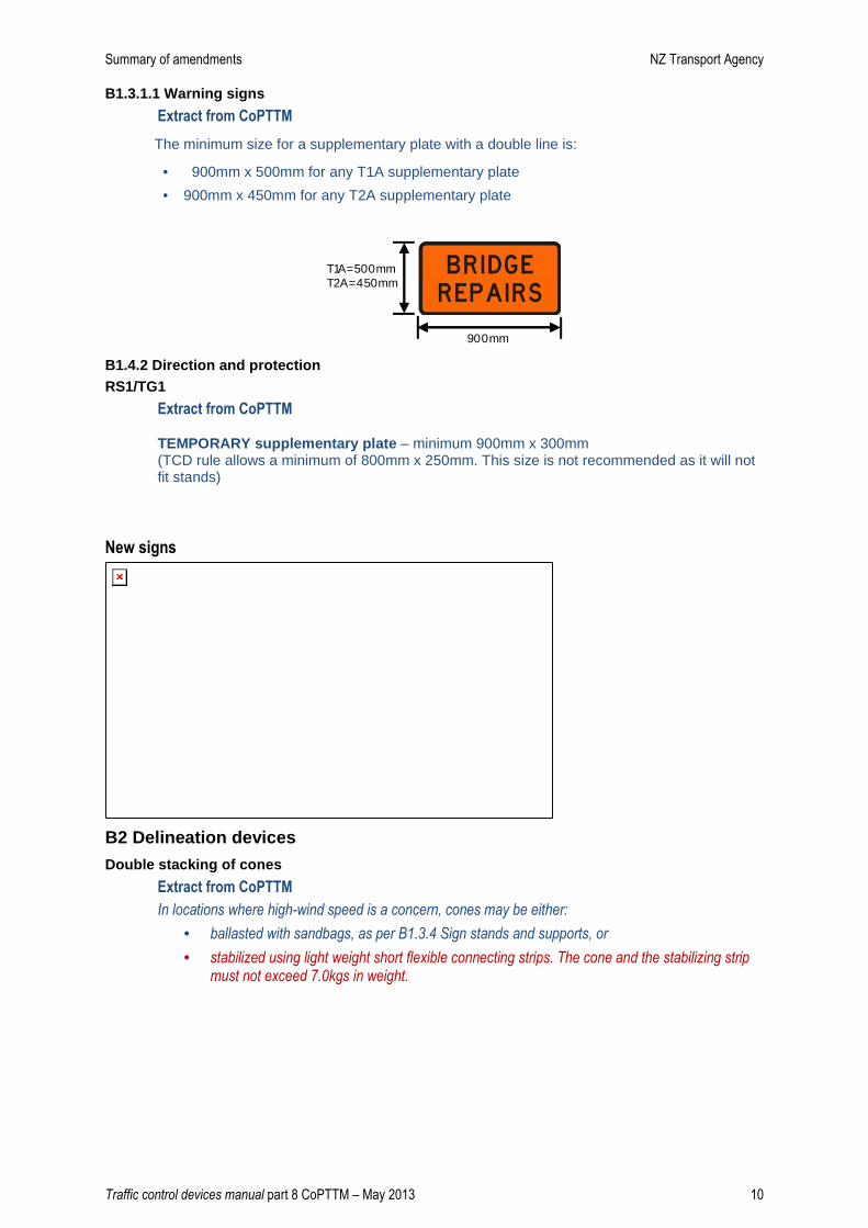
B1.3.1.1 Warning signs
Extract from CoPTTM
The minimum size for a supplementary plate with a double line is:
• 900mm x 500mm for any T1A supplementary plate
• 900mm x 450mm for any T2A supplementary plate
B1.4.2 Direction and protection RS1/TG1
Extract from CoPTTM
TEMPORARY supplementary plate – minimum 900mm x 300mm (TCD rule allows a minimum of 800mm x 250mm. This size is not recommended as it will not fit stands)
New signs
B2 Delineation devices
Double stacking of cones
Extract from CoPTTM
In locations where high-wind speed is a concern, cones may be either:
• ballasted with sandbags, as per B1.3.4 Sign stands and supports, or
• stabilized using light weight short flexible connecting strips. The cone and the stabilizing strip must not exceed 7.0kgs in weight.
900mm
T1A=500mmT2A=450mm
Summary of amendments NZ Transport Agency
Traffic control devices manual part 8 CoPTTM – May 2013 11
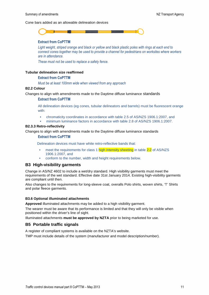
Cone bars added as an allowable delineation devices
Extract from CoPTTM
Light weight, striped orange and black or yellow and black plastic poles with rings at each end to connect cones together may be used to provide a channel for pedestrians on worksites where workers are in attendance.
These must not be used to replace a safety fence.
Tubular delineation size reaffirmed
Extract from CoPTTM
Must be at least 100mm wide when viewed from any approach
B2.2 Colour
Changes to align with amendments made to the Daytime diffuse luminance standards Extract from CoPTTM
All delineation devices (eg cones, tubular delineators and barrels) must be fluorescent orange with:
• chromaticity coordinates in accordance with table 2.5 of AS/NZS 1906.1:2007, and • minimum luminance factors in accordance with table 2.8 of AS/NZS 1906.1:2007.
B2.3.3 Retro-reflectivity Changes to align with amendments made to the Daytime diffuse luminance standards
Extract from CoPTTM
Delineation devices must have white retro-reflective bands that:
• meet the requirements for class 1 high intensity sheeting in table 2.2 of AS/NZS 1906.1:2007, and
• conform to the number, width and height requirements below.
B3 High-visibility garments
Change in AS/NZ 4602 to include a wet/dry standard. High visibility garments must meet the requirements of the wet standard. Effective date 31st January 2014. Existing high-visibility garments are compliant until then.
Also changes to the requirements for long-sleeve coat, overalls Polo shirts, woven shirts, ‘T’ Shirts and polar fleece garments.
B3.6 Optional illuminated attachments Approved illuminated attachments may be added to a high visibility garment.
The wearer must be aware that its performance is limited and that they will only be visible when positioned within the driver’s line of sight.
Illuminated attachments must be approved by NZTA prior to being marketed for use.
B5 Portable traffic signals
A register of compliant systems is available on the NZTA’s website.
TMP must include details of the system (manufacturer and model description/number).
Summary of amendments NZ Transport Agency
Traffic control devices manual part 8 CoPTTM – May 2013 12
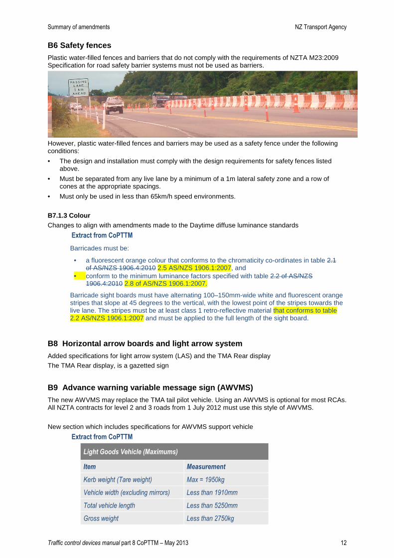
B6 Safety fences
Plastic water-filled fences and barriers that do not comply with the requirements of NZTA M23:2009 Specification for road safety barrier systems must not be used as barriers.
However, plastic water-filled fences and barriers may be used as a safety fence under the following conditions:
• The design and installation must comply with the design requirements for safety fences listed above.
• Must be separated from any live lane by a minimum of a 1m lateral safety zone and a row of cones at the appropriate spacings.
• Must only be used in less than 65km/h speed environments.
B7.1.3 Colour Changes to align with amendments made to the Daytime diffuse luminance standards
Extract from CoPTTM
Barricades must be:
• a fluorescent orange colour that conforms to the chromaticity co-ordinates in table 2.1 of AS/NZS 1906.4:2010 2.5 AS/NZS 1906.1:2007, and
• conform to the minimum luminance factors specified with table 2.2 of AS/NZS 1906.4:2010 2.8 of AS/NZS 1906.1:2007.
Barricade sight boards must have alternating 100–150mm-wide white and fluorescent orange stripes that slope at 45 degrees to the vertical, with the lowest point of the stripes towards the live lane. The stripes must be at least class 1 retro-reflective material that conforms to table 2.2 AS/NZS 1906.1:2007 and must be applied to the full length of the sight board.
B8 Horizontal arrow boards and light arrow system
Added specifications for light arrow system (LAS) and the TMA Rear display
The TMA Rear display, is a gazetted sign
B9 Advance warning variable message sign (AWVMS)
The new AWVMS may replace the TMA tail pilot vehicle. Using an AWVMS is optional for most RCAs. All NZTA contracts for level 2 and 3 roads from 1 July 2012 must use this style of AWVMS.
New section which includes specifications for AWVMS support vehicle
Extract from CoPTTM
Light Goods Vehicle (Maximums)
Item Measurement
Kerb weight (Tare weight) Max = 1950kg
Vehicle width (excluding mirrors) Less than 1910mm
Total vehicle length Less than 5250mm
Gross weight Less than 2750kg

Summary of amendments NZ Transport Agency
Traffic control devices manual part 8 CoPTTM – May 2013 13
Very Light Trailer (Maximums)
Item Measurement
Kerb weight (Tare weight) Max = 750kg
Vehicle width (excluding mirrors) Less than 1500mm
Total vehicle length Less than 5000mm
Gross weight Less than 1500kg
B10 Mobile variable message sign (VMS)
Specifications for VMS are now set out in P37 (P35 and P36 for messages)
B11 Truck-mounted attenuators (TMAs)
Support Vehicle Weights NZTA has established the following minimum truck weights:
Manufacturer / Supplier TMA System Minimum Truck Weight
Barrier Systems Inc UMAD-70k 9000 kg (- 400 kg)
Energy Absorption Systems Inc Alpha-70k 6400 kg (- 400 kg)
Traffix Devices Inc Scorpion 10,000 6400 kg (- 400 kg)
B12 Barrier systems
Specifications for barrier system now in M23 Specification for road safety barrier systems Appendix B: Requirements for approved temporary barrier systems
NZTA has adopted new standard From 1 November 2012 the NZTA has adopted the AASHTO Manual for Assessing Safety Hardware (MASH-1) as the nominal standard for road safety hardware systems installed on the state highway network.
B13 Temporary speed humps
New section has been added
Extract from CoPTTM
Speed hump systems must be approved by the NZTA before use.
Details of testing criteria and independent testing are available from the NZTA
Register of approved speed humps on CoPTTM website

Summary of amendments NZ Transport Agency
Traffic control devices manual part 8 CoPTTM – May 2013 14
B14 Warning systems
New section on warning systems which covers flashing beacons and Xenon warning lights.
Flashing beacons
Extract from CoPTTM
Flashing or revolving amber beacons refer to roof mounted devices which consist of a light, encapsulated in a casing and may either flash (strobe) or appear to flash when circled by a rotating reflector. The beacon(s) are to be mounted on a vehicle in such positions as to give a 360° uninterrupted view in the horizontal plane.
Note: Vehicle hazard warning lights are not beacons.
Land transport Rule: Vehicle lighting 2004
All flashing beacons used in New Zealand must comply with section 11 of the Land transport Rule: Vehicle lighting 2004.
ECE Regulation 65
The flash conditions, the amber colour coordinates and the light output of the beacon must comply with the criteria specified below which was identified from within ECE Regulation 65. Compliance with these conditions must be contingent on certification obtained from an IANZ accredited laboratory.
Note: The light output conditions permit beacons with a single light output level as well as those having dual (night/day) light output levels.
Xenon warning lights Xenon warning lights, used on AWVMS and LAS, give advance warning to alert approaching road users
Note: These cannot be replaced by Halogen or LED lights
Summary of amendments NZ Transport Agency
Traffic control devices manual part 8 CoPTTM – May 2013 15
Section C - Static Operations
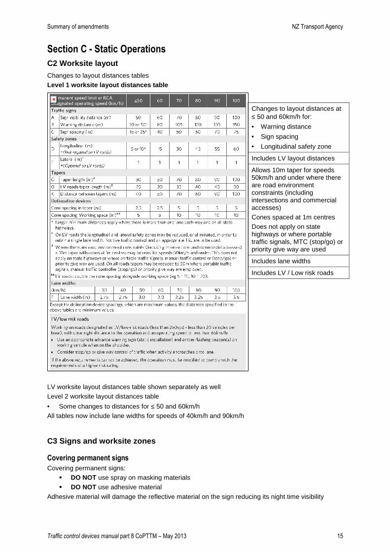
C2 Worksite layout
Changes to layout distances tables
Level 1 worksite layout distances table
LV worksite layout distances table shown separately as well
Level 2 worksite layout distances table
• Some changes to distances for ≤ 50 and 60km/h
All tables now include lane widths for speeds of 40km/h and 90km/h
C3 Signs and worksite zones
Covering permanent signs
Covering permanent signs:
� DO NOT use spray on masking materials
� DO NOT use adhesive material
Adhesive material will damage the reflective material on the sign reducing its night time visibility
Changes to layout distances at ≤ 50 and 60km/h for:
• Warning distance
• Sign spacing
• Longitudinal safety zone
Includes LV layout distances
Allows 10m taper for speeds 50km/h and under where there are road environment constraints (including intersections and commercial accesses)
Cones spaced at 1m centres
Does not apply on state highways or where portable traffic signals, MTC (stop/go) or priority give way are used
Includes lane widths
Includes LV / Low risk roads
Summary of amendments NZ Transport Agency
Traffic control devices manual part 8 CoPTTM – May 2013 16
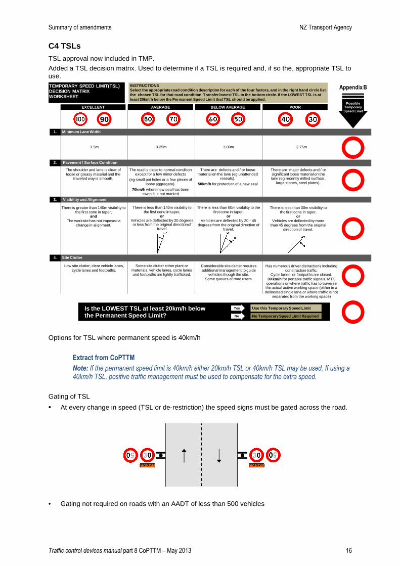
C4 TSLs
TSL approval now included in TMP.
Added a TSL decision matrix. Used to determine if a TSL is required and, if so the, appropriate TSL to use.
The road is close to normal condition except for a few minor defects
(eg small pot holes or a few pieces of loose aggregate).
70km/h where new seal has been swept but not marked
There are defects and / or loose material on the lane (eg unattended
reseals).50km/h for protection of a new seal
The shoulder and lane is clear of loose or greasy material and the
traveled way is smooth.
90
2.75m 3.5m 3.25m 3.00m
Possible Temporary Speed Limit
There is greater than 140m visibility to the first cone in taper,
andThe worksite has not imposed a
change in alignment.
TEMPORARY SPEED LIMIT(TSL)DECISION MATRIX WORKSHEET
There are major defects and / or significant loose material on the lane (eg recently milled surface ,
large stones, steel plates).
There is less than 140m visibility to the first cone in taper,
orVehicles are deflected by 20 degrees or less from the original directionof
travel.
There is less than 60m visibility to the first cone in taper,
orVehicles are deflected by 20 - 45
degrees from the original direction of travel.
There is less than 30m visibility to the first cone in taper,
orVehicles are deflected by more
than 45 degrees from the original direction of travel.
Low site clutter, clear vehicle lanes, cycle lanes and footpaths.
Some site clutter either plant or materials, vehicle lanes, cycle lanes and footpaths are lightly trafficked.
Considerable site clutter requires additional management to guide
vehicles though the site. Some queues of road users.
Has numerous driver distractions including construction traffic.
Cycle lanes or footpaths are closed.30 km/h for portable traffic signals, MTC
operations or where traffic has to traverse the actual active working space (either in a delineated single lane or where traffic is not
separated from the working space)
AVERAGE BELOW AVERAGE POOR
Minimum Lane Width1.
Pavement / Surface Condition2.
Visibility and Alignment3.
Site Clutter4.
INSTRUCTIONS Select the appropriate road condition description f or each of the four factors, and in the right hand circle list the chosen TSL for that road condition. Transfer l owest TSL to the bottom circle. If the LOWEST TSL i s at least 20km/h below the Permanent Speed Limit that TS L should be applied.
EXCELLENT
No Temporary Speed Limit Required
Use this Temporary Speed LimitYes
No
Is the LOWEST TSL at least 20km/h below the Permanent Speed Limit?
Appendix B
Options for TSL where permanent speed is 40km/h
Extract from CoPTTM
Note: If the permanent speed limit is 40km/h either 20km/h TSL or 40km/h TSL may be used. If using a 40km/h TSL, positive traffic management must be used to compensate for the extra speed.
Gating of TSL
• At every change in speed (TSL or de-restriction) the speed signs must be gated across the road.
• Gating not required on roads with an AADT of less than 500 vehicles
Summary of amendments NZ Transport Agency
Traffic control devices manual part 8 CoPTTM – May 2013 17
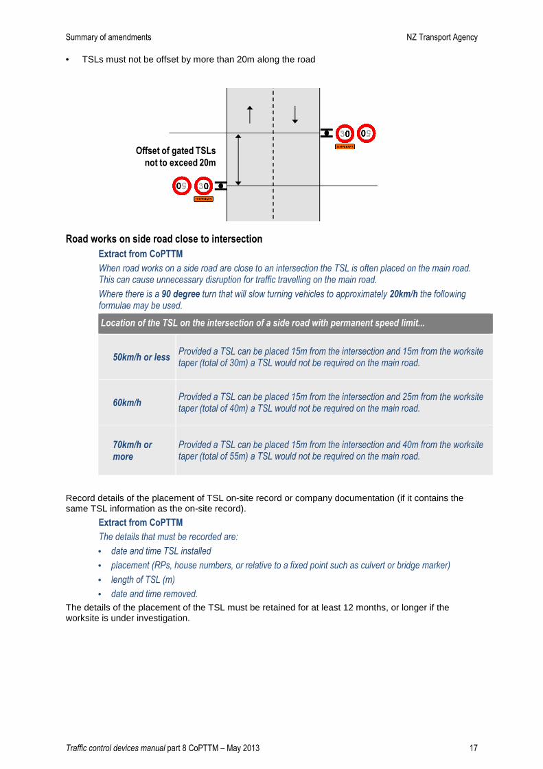
• TSLs must not be offset by more than 20m along the road
Offset of gated TSLs
not to exceed 20m
Road works on side road close to intersection
Extract from CoPTTM
When road works on a side road are close to an intersection the TSL is often placed on the main road. This can cause unnecessary disruption for traffic travelling on the main road.
Where there is a 90 degree turn that will slow turning vehicles to approximately 20km/h the following formulae may be used.
Location of the TSL on the intersection of a side road with permanent speed limit...
50km/h or less Provided a TSL can be placed 15m from the intersection and 15m from the worksite taper (total of 30m) a TSL would not be required on the main road.
60km/h Provided a TSL can be placed 15m from the intersection and 25m from the worksite taper (total of 40m) a TSL would not be required on the main road.
70km/h or
more
Provided a TSL can be placed 15m from the intersection and 40m from the worksite taper (total of 55m) a TSL would not be required on the main road.
Record details of the placement of TSL on-site record or company documentation (if it contains the same TSL information as the on-site record).
Extract from CoPTTM
The details that must be recorded are:
• date and time TSL installed
• placement (RPs, house numbers, or relative to a fixed point such as culvert or bridge marker)
• length of TSL (m)
• date and time removed.
The details of the placement of the TSL must be retained for at least 12 months, or longer if the worksite is under investigation.
Summary of amendments NZ Transport Agency
Traffic control devices manual part 8 CoPTTM – May 2013 18
C5 Delineation devices
Extract from CoPTTM
Use and placement of delineation devices
On all level 2 and 3 layouts cones must be installed along the edgeline, from the first RS1 (RG-4) Temporary Speed Limit sign to the start of the taper or working space where no taper is installed
Where the edgeline is well defined (ie by a clean kerb and channel, etc) this line of cones is not required
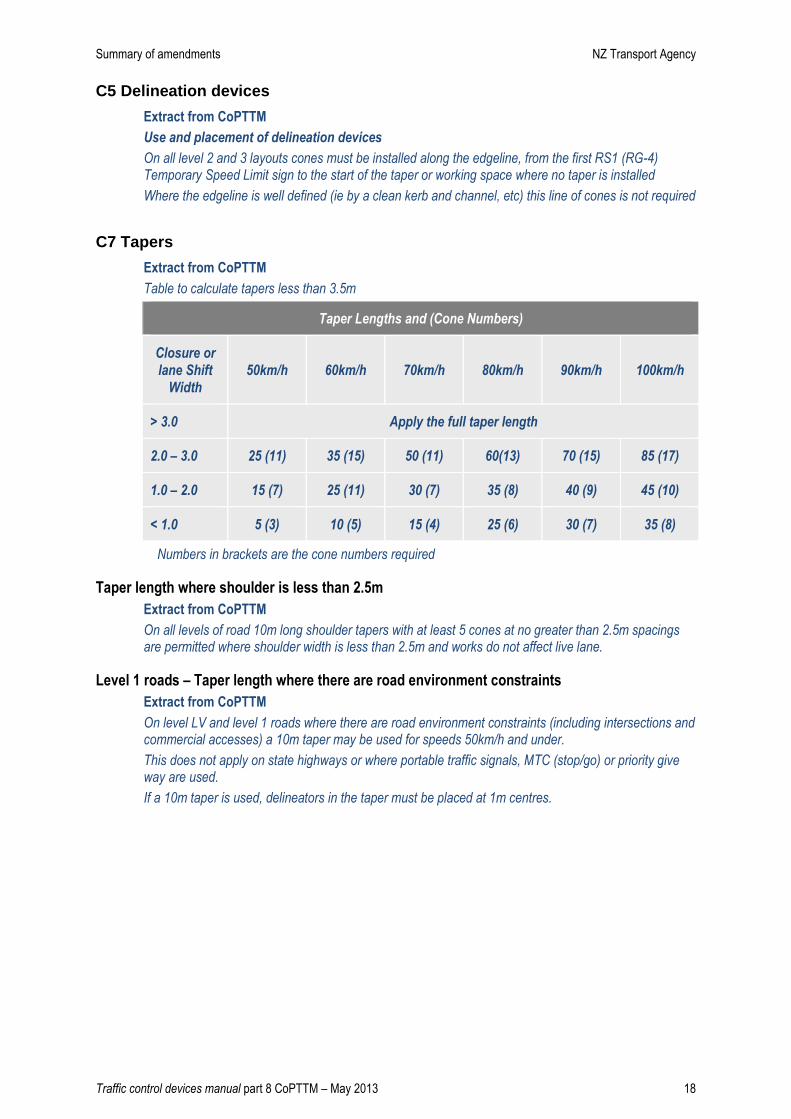
C7 Tapers
Extract from CoPTTM
Table to calculate tapers less than 3.5m
Taper Lengths and (Cone Numbers)
Closure or
lane Shift
Width
50km/h 60km/h 70km/h 80km/h 90km/h 100km/h
> 3.0 Apply the full taper length
2.0 – 3.0 25 (11) 35 (15) 50 (11) 60(13) 70 (15) 85 (17)
1.0 – 2.0 15 (7) 25 (11) 30 (7) 35 (8) 40 (9) 45 (10)
< 1.0 5 (3) 10 (5) 15 (4) 25 (6) 30 (7) 35 (8)
Numbers in brackets are the cone numbers required
Taper length where shoulder is less than 2.5m
Extract from CoPTTM
On all levels of road 10m long shoulder tapers with at least 5 cones at no greater than 2.5m spacings are permitted where shoulder width is less than 2.5m and works do not affect live lane.
Level 1 roads – Taper length where there are road environment constraints
Extract from CoPTTM
On level LV and level 1 roads where there are road environment constraints (including intersections and commercial accesses) a 10m taper may be used for speeds 50km/h and under.
This does not apply on state highways or where portable traffic signals, MTC (stop/go) or priority give way are used.
If a 10m taper is used, delineators in the taper must be placed at 1m centres.

Summary of amendments NZ Transport Agency
Traffic control devices manual part 8 CoPTTM – May 2013 19
C8 Shoulder and lane closures
Shoulder closure on Level 1 and 2 roads with speed limits of less than 65km/h
Extract from CoPTTM
Work on the berm or footpath does not require advance warning however traffic management must be provided where pedestrians or cyclists are affected
Advance warning T1A/B (TW-1) and works end TG2 (TW16) are optional if:
• the work vehicle (light truck or smaller) is parked in a legal parallel car park, and
• the vehicle is only accessed from the off traffic side
Large plant and machinery must not be used in this situation; a more substantial closure is required.
Berm
Parking
Lan
e
Traffic La
ne
Foo
tpath
Wor
k ve
hicl
e
Where work is carried out in the legal parking lane, the following minimum standard of TTM must be provided:
• a 10m taper in front of the work vehicle
• cones alongside the work vehicle and the working space
• a longitudinal safety zone
• a 1m lateral safety zone along the working space
• at least one amber flashing beacon
• a T1A (or other appropriate advance warning sign) mounted on the back of the work vehicle
• the work vehicle is no larger than a light truck. Large plant and machinery must not be used in this situation; a more substantial closure is required.
Berm
Parking
Lane
Traffic Lan
e
Foo
tpath
Wor
k ve
hicl
e
D
E
G=10m
T1A
Summary of amendments NZ Transport Agency
Traffic control devices manual part 8 CoPTTM – May 2013 20
C8.2.3 Level 2 lane closures
Extract from CoPTTM
The lane closure sign requires a supplementary sign displaying the distance to the lane closure.
Depending on worksite requirements, the first lane closure sign is placed at least one sign spacing in advance of the start of the taper.
For multiple lane closures, the second lane closure must be signed at least one sign spacing in advance of the start of the second taper.
Multiples of 100m may be used instead of the sign spacing.
Centre lane closure
Extract from CoPTTM
On roads with three or more lanes in one direction, centre lane closures are not permitted.
Exception The only exception to this is a level 1 road which is not a state highway and has a permanent speed of 50km/h or less.
In this exception only, centre lane closures are permitted provided:
• traffic merges only in one direction
• there is a definite lane shift (either left or right), and
• tapers move traffic to the side of greatest capacity.
In all other cases, where work must be conducted in a centre lane, the lane(s) on either the left or right must also be closed.
C8.2.7 Contraflow on multilane road
Extract from CoPTTM
Where a contraflow is established on a multilane road, a longitudinal safety zone of 2xD is to be established to provide separation of vehicles.
C8.2.8 Allowing heavy vehicles room to manoeuvre
Extract from CoPTTM
Cones in a channel must be offset by a minimum of 10m where the direction changes allowing for heavy vehicles to manoeuvre without hitting the cones.

Summary of amendments NZ Transport Agency
Traffic control devices manual part 8 CoPTTM – May 2013 21
Working next to flexible barrier
Extract from CoPTTM
For short term static works the same approach will be adopted as for work behind cones. This is to require a 1m lateral safety space between the wire-rope barrier and the working space.
For long term works allowance must be made for barrier deflection as detailed by the manufacturer.
Mobile Ops can work up to the barrier.
Examples of how to set up for work next to flexible barrier
2 + 2 lane road
• close lane each side (usually a mobile closure).
2 + 1 lane road
• close one of 2 lanes. Work from the closed lane with a coned 1m lateral safety zone
• a TSL and positive traffic management must be applied to the single lane.
1 + 1 lane road
• place a centre line type static closure with a TSL and positive traffic management.
Construction or re-construction of an existing road surface
MTC or portable traffic signals may be used to temporarily halt traffic while work is underway:
• the equipment must stop and work ceases while traffic is moving through the site
• each work vehicle must have ‘Pass with Care’ on it, and travel in direction of traffic
Lane delineation during sealing and resealing activities on level LV, 1 and 2 roads
For chip sealing and resealing activities under MTC control:
Cones with the following spacings may be used in lane delineation to separate the traffic from the work:
• 5m spacing can be increased to 10m
• 10m spacing can be increased to 20m.
Note: This above exemption applies only to full width chip sealing and resealing worksites. It does not apply to chip sealing of patch repairs. It does not apply to the cone spacing in tapers.
C9 Road closures and detours
C9.2.4 Motorway Closures If motorway is completely closed in one direction or both directions, reinforce normal TTM by adding a double line of cones either continuous or chicaned at a normal warning distance from the working space.
TMA vehicles parked outside this inner cordon must be parked with their attenuators down and facing the normal direction of traffic (vehicles inside the cordoned worksite are not subject to this requirement).
Gore area and deceleration lane
A gore area is an area of seal at an on or off ramp located outside the edgelines of the ramp
Gore area and acceleration lane
Extract from CoPTTM
An acceleration lane is an area at an on ramp which allows drivers to increase speed and safely merge with traffic.
When working in the gore area or acceleration lane on level 2 and level 3 roads, the ramp on which the work is being carried out must be closed.
Summary of amendments NZ Transport Agency
Traffic control devices manual part 8 CoPTTM – May 2013 22
C10 Positive traffic management
Equipment required
Extract from CoPTTM
The wearing of clothing that obscures an MTC’s view of approaching vehicles (excluding PPE) and the use of devices that reduce the awareness of an MTC to the sound of approaching vehicles are forbidden.
Location of MTC
Extract from CoPTTM
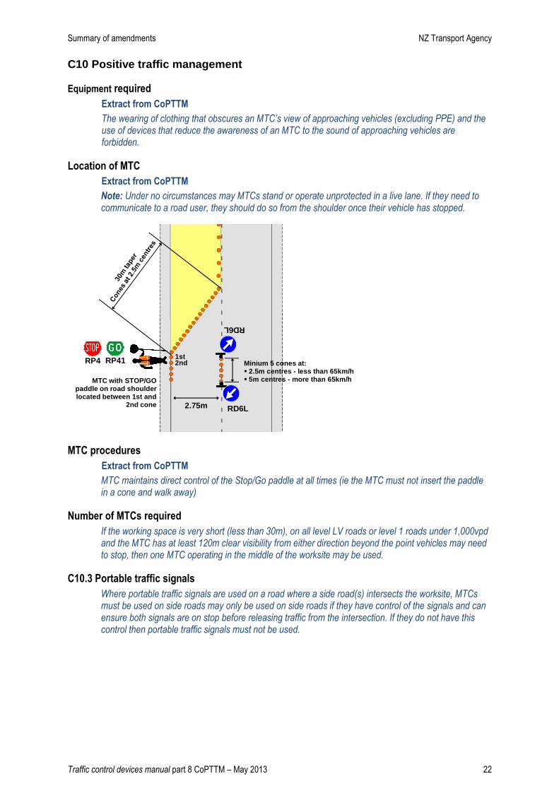
Note: Under no circumstances may MTCs stand or operate unprotected in a live lane. If they need to communicate to a road user, they should do so from the shoulder once their vehicle has stopped.
2.75m
RP41RP4
RD6L
RD6L
1st2nd Minium 5 cones at:
� 2.5m centres - less than 65km/h� 5m centres - more than 65km/hMTC with STOP/GO
paddle on road shoulder located between 1st and
2nd cone
MTC procedures
Extract from CoPTTM
MTC maintains direct control of the Stop/Go paddle at all times (ie the MTC must not insert the paddle in a cone and walk away)
Number of MTCs required
If the working space is very short (less than 30m), on all level LV roads or level 1 roads under 1,000vpd and the MTC has at least 120m clear visibility from either direction beyond the point vehicles may need to stop, then one MTC operating in the middle of the worksite may be used.
C10.3 Portable traffic signals
Where portable traffic signals are used on a road where a side road(s) intersects the worksite, MTCs must be used on side roads may only be used on side roads if they have control of the signals and can ensure both signals are on stop before releasing traffic from the intersection. If they do not have this control then portable traffic signals must not be used.

Summary of amendments NZ Transport Agency
Traffic control devices manual part 8 CoPTTM – May 2013 23
C11 TTM installation, management and removal
New part - Minimising the effect of ghosts markings
Extract from CoPTTM
The standard for line removal is detailed in the NZTA SOMAC (SMO32).
The NZTA SOMAC (SMO32) states:
Using the principles outlined in the NZRF Line Removal Guide, the Contractor must remove all:
a. Paint that has been applied outside the specified tolerances, including all run-ins and runouts
b. If instructed by the Engineer, existing markings so:
• A satisfactory level of removal is achieved in accordance with the NZRF Line Removal Guide. Only sufficient marking material shall be removed so that it cannot be distinguished from the driver’s eye height (nominal 1.2 m). (Note: it is acceptable for some marking material to remain in the interstices of the pavement surface)
• The final surface texture is similar to the surrounding pavement.
Blacking out markings (using a paint marking system) prior to a permanent removal method may be used (with the Engineer's approval) as a temporary measure until permanent removal can be completed.
When required the Contractor shall mill existing profiled markings prior to remarking. It may be desirable to leave a thin layer of old marking material on the road prior to remarking so as not to damage the pavement surfacing.
C11.2.4 Installing signs on level LV and level 1 roads
Extract from CoPTTM
Vehicles used to install TTM equipment on level LV and level 1 roads must have:
• amber flashing beacon(s) visible to all approaching traffic
• signs, either T1A (TW-1) and RD6R/L (RG-17/34), or TV4 and RD6L/R (TW-34).
C11.2.8 Redundant TTM equipment
Extract from CoPTTM
All redundant TTM equipment must be removed from the site or placed in a safe secure location.
Redundant equipment is defined as that TTM equipment not in current use for TTM. This includes TTM equipment not required when the site is left unattended.
Redundant TTM signs, sign supports, sign bases and delineators, may be stored on site provided that:
• the equipment does not remain on-site and unused for a period greater than 48 hours
• the equipment is stored in a safe location where it will not pose a hazard to any person or property
• STMS’s identify and appropriately manage the site specific hazards as they apply to this matter
• the equipment must not be stored or placed on an open footpath or cycle way
• the equipment must be stored at least 5m from edge line where no footpath exists or, where one exists, in the back berm area (i.e. between footpath and boundary)
Redundant TTM equipment must not be left standing nor deployed.
Summary of amendments NZ Transport Agency
Traffic control devices manual part 8 CoPTTM – May 2013 24
C12 Unattended worksites and night work
Preparing worksite to be left unattended
Extract from CoPTTM
As part of preparing the worksite to be left unattended, also consider the following actions:
• reduce the size of the worksite as much as possible
• if TSLs have been installed, consider whether these are still required or whether the TSL should be changed (remember that changes to the TSL must be approved)
• sweep any loose material from the sealed road surface
• check that all signs are ballasted and positioned correctly
• check that all delineation devices are clean and positioned correctly.
If the worksite is to be left unattended overnight, consider the following additional actions:
• place amber flashing lamps on each corner of any barricade/fence, to help make the worksite and hazard more identifiable
• ensure there is enough guidance for road users as they pass by or through the worksite – add additional cones if required (for example if the closure is on a corner or over a hill, extend the cones further towards the oncoming traffic to provide more guidance).
Amber flashing warning lamps
Extract from CoPTTM
On level LV and level 1 roads where there is a hazard on a footpath or cycle lane, amber flashing warning lamps may be placed on any barricades and fences.
No longer mandatory
C13 Pedestrians and cyclists
Footpath widths – 9m, 1.2m, 2.0m
Extract from CoPTTM
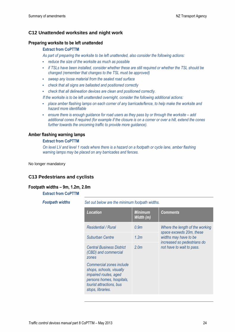
Footpath widths Set out below are the minimum footpath widths.
Location Minimum Width (m)
Comments
Residential / Rural 0.9m Where the length of the working space exceeds 20m, these widths may have to be increased so pedestrians do not have to wait to pass.
Suburban Centre 1.2m
Central Business District (CBD) and commercial zones
Commercial zones include shops, schools, visually impaired routes, aged persons homes, hospitals, tourist attractions, bus stops, libraries.
2.0m
Summary of amendments NZ Transport Agency
Traffic control devices manual part 8 CoPTTM – May 2013 25
Alternative routes
Extract from CoPTTM
Where the activity impacts a footpath and minimum footpath widths cannot be maintained, alternative routes with a firm smooth surface and no trip hazards are to be provided in the following order of preference:
1. On side of road reserve away from the carriageway, or
2. Between the working space and carriageway (but not into the live lane), or
3. Into the carriageway (either in a parking lane or a suitably delineated and protected section of the existing traffic lane)
4. Across the carriageway to a footpath on the opposite side with delineation of the crossing points and kerb ramps to assist mobility vehicles and pushchairs etc
Note: This option is strongly discouraged and is not to be used if the above options are feasible
5. Use footpath controllers to guide pedestrians around the operation
Note: Only use this method when there is no alternative temporary footpath safely available.
Footpath closed please use other side
Only used on level LV and level 1 roads with permanent speed 65km/h or less.
Pedestrians must not be required to cross more than 2 lanes without a central pedestrian refuge.
When using this sign it must be shown in the TMP with sight distances to the sign of at least:
o 75m at 50km/h
o 100m at 60km/h.
Footpath controller
Extract from CoPTTM
Where there is no alternative footpath safely available, sufficient footpath controllers are to be provided to guide pedestrians around the operation. A footpath controller may be used to manage pedestrians, cyclists or other road users, and road workers entering and leaving working spaces, including people involved in events.
They can also be used to guide pedestrians where appropriate footpath widths cannot be achieved.
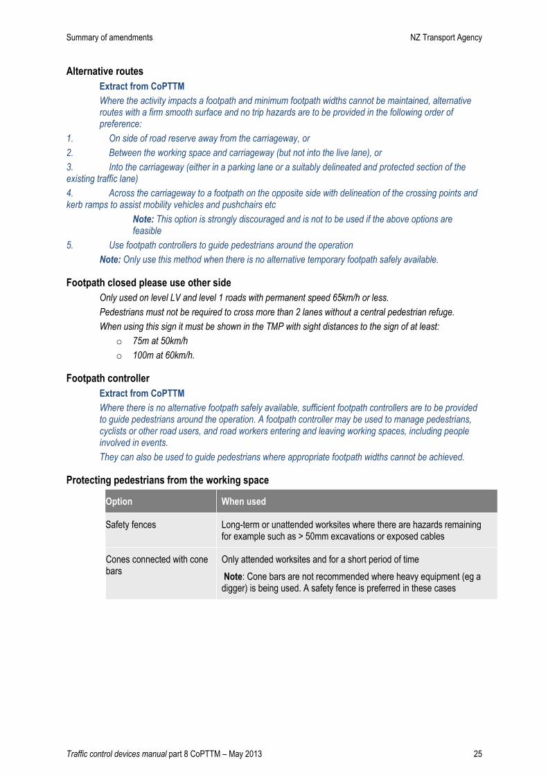
Protecting pedestrians from the working space
Option When used
Safety fences Long-term or unattended worksites where there are hazards remaining for example such as > 50mm excavations or exposed cables
Cones connected with cone bars
Only attended worksites and for a short period of time
Note: Cone bars are not recommended where heavy equipment (eg a digger) is being used. A safety fence is preferred in these cases

Summary of amendments NZ Transport Agency
Traffic control devices manual part 8 CoPTTM – May 2013 26
Footpath diverted into carriageway
Extract from CoPTTM
If the footpath is to be diverted into the carriageway then the traffic side of the walkway must be delineated
from the traffic by either:
Option When used
Lateral safety zone
required with
delineation
Barriers Long-term worksites 0.5m
Safety fences Long-term worksites
Any unattended worksites
Attended worksites on level 2 roads and state highways
1m
Cones connected with cone bars
Attended worksites on level LV and level 1 roads (except state highways) and only for a short period of time
1m
Cycle lane merged with traffic lane
Extract from CoPTTM
Where because of road environment constraints there is insufficient width to fit a replacement cycle lane while maintaining existing traffic lanes, a contractor may consider merging the cyclists into the traffic lane.
To use this option the contractor must have TMP approval and must provide a threshold treatment including a TSL to enable the cyclists to merge into the traffic lane.
Cycle lane widths have changed
Extract from CoPTTM
Set out below are the minimum temporary cycle lane widths.
Type of lane Speed Minimum Width (m)
Single direction cycle lane Speed limit does not exceed 50km/h
1.0m *
Single direction cycle lane Speed limit exceeds 50km/h 1.5m
Two-way cycle lane Any speed 2.0m
Shared footpath and cycle way Any speed 2.2m #
* Note: A minimum lane width of 1.5m is required if the temporary cycle lane is uphill as riders tend to pump
their cycles from side to side as they climb the hill.
# Note: Where a shared footpath and cycle way is reduced to less than 2.2m wide, cyclists should be
excluded by closing the cycle way.
Summary of amendments NZ Transport Agency
Traffic control devices manual part 8 CoPTTM – May 2013 27
C14 Work vehicles, equipment and materials
Parking and storage of plant and equipment
Extract from CoPTTM
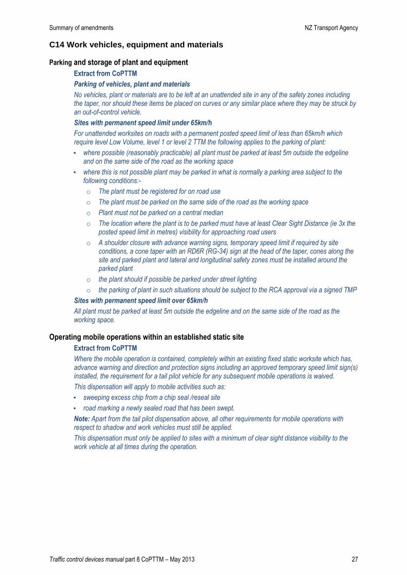
Parking of vehicles, plant and materials
No vehicles, plant or materials are to be left at an unattended site in any of the safety zones including the taper, nor should these items be placed on curves or any similar place where they may be struck by an out-of-control vehicle.
Sites with permanent speed limit under 65km/h
For unattended worksites on roads with a permanent posted speed limit of less than 65km/h which require level Low Volume, level 1 or level 2 TTM the following applies to the parking of plant:
• where possible (reasonably practicable) all plant must be parked at least 5m outside the edgeline and on the same side of the road as the working space
• where this is not possible plant may be parked in what is normally a parking area subject to the following conditions:-
o The plant must be registered for on road use
o The plant must be parked on the same side of the road as the working space
o Plant must not be parked on a central median
o The location where the plant is to be parked must have at least Clear Sight Distance (ie 3x the posted speed limit in metres) visibility for approaching road users
o A shoulder closure with advance warning signs, temporary speed limit if required by site conditions, a cone taper with an RD6R (RG-34) sign at the head of the taper, cones along the site and parked plant and lateral and longitudinal safety zones must be installed around the parked plant
o the plant should if possible be parked under street lighting
o the parking of plant in such situations should be subject to the RCA approval via a signed TMP
Sites with permanent speed limit over 65km/h
All plant must be parked at least 5m outside the edgeline and on the same side of the road as the working space.
Operating mobile operations within an established static site
Extract from CoPTTM
Where the mobile operation is contained, completely within an existing fixed static worksite which has, advance warning and direction and protection signs including an approved temporary speed limit sign(s) installed, the requirement for a tail pilot vehicle for any subsequent mobile operations is waived.
This dispensation will apply to mobile activities such as:
• sweeping excess chip from a chip seal /reseal site
• road marking a newly sealed road that has been swept.
Note: Apart from the tail pilot dispensation above, all other requirements for mobile operations with respect to shadow and work vehicles must still be applied.
This dispensation must only be applied to sites with a minimum of clear sight distance visibility to the work vehicle at all times during the operation.

Summary of amendments NZ Transport Agency
Traffic control devices manual part 8 CoPTTM – May 2013 28
C17 Light arrow system, horizontal arrow board, TMA and variable message sign (VMS)
This section now includes TMA and VMS
Location of arrow boards
Extract from CoPTTM
Arrow boards for static operations must be positioned in the centre of the closed lane and longitudinal and lateral safety zones must be provided in advance of the arrow board and between the arrow board and live traffic lane respectively.
C18 Barriers
A comprehensive section has been written about the requirements for temporary barriers. It gives:
• Advice on when to use
• Advice on what to use
• Essentials for a safe setup
Important messages:
• Barriers must be anchored and linked
• Barriers must have either a crash worthy terminal or a correctly flared end
• Use NZTA M23 to find out about compliant systems
A hands-on barrier workshop is available to help people understand barrier requirements
Workin
g
Space
Lateral S
afety
Zone
Longitudinal
Safety Z
one
Horizo
ntal
arrow board

Summary of amendments NZ Transport Agency
Traffic control devices manual part 8 CoPTTM – May 2013 29
Section D – Mobile operations
D1 General
Mobile operation definition
Mobile closure � A normally continuously moving activity or work operation carried out within the road
reserve that may also stop briefly at a particular location for a period of no more than 10 minutes.
Note: Activities like mole ploughing and drain digging move along the road but they move too slowly to be considered mobile operations. These types of activities must be planned and managed as static operations.
Semi-static closure � A short term activity or work operation that is carried out on the carriageway of a road at a
particular location that takes more than 10 minutes, and less than 1 hour, to complete.
Note: The 10 minutes to 1 hour timeframe applies only to the working period and does not include the time required to install and remove the TTM devices on the worksite. No work is to be undertaken during set-up or removal of TTM equipment.
Special operations � These are mobile operations which may vary the requirements of the above two categories or
provide additional requirements to enhance safety for certain situations
� Included in this category are:
o inspections
o kerbside collections
o road marking
o rolling blocks.
TV2 (TW-26) road works sign
Extract from CoPTTM
Where work is being carried out in a live lane on a two-way two-lane road, and a lead pilot vehicle is not required, a front mounted TV2 (TW-26) road works sign is required on the leading work vehicle where the speed limit is greater than 65km/h.
Signs on cars or light utility vehicles
Extract from CoPTTM
Where cars or light utilities are used for inspections, sports events and high speed data capture, only the appropriate supplementary sign will be required eg road inspection, cycle race, road works.
Signs on work vehicle more than 5m from edgeline
Extract from CoPTTM
Where the work vehicle is more than 5m from the edgeline the work vehicle must have either:
• the appropriate advance warning sign with supplementary plate if required and the RD6R (RG-34) sign
or
• the TV4 (TW-34) PASS WITH CARE sign and the RD6R (RG-34) sign.

Summary of amendments NZ Transport Agency
Traffic control devices manual part 8 CoPTTM – May 2013 30
When RD6L/R (RG-17/34) signs can be omitted from the TV4 (TW-34) Pass with Care sign
Extract from CoPTTM
Where a horizontal arrow board is used in a mobile operation the TV4 (TW-34) Pass With Care sign will be retained but the RD6L/R (RG-17/34) signs are not to be used.
Where the situation is constantly changing (eg rolling, grading, road marking, water cart, drag brooming operations on two lane one way roads) and it is impractical to change the RD6L/R (RG-17/34) sign frequently, this component may be omitted.
LAS operation now included in this section
Extract from CoPTTM
Caution mode lane closed
A part of the roadway which is used for driving is closed and it is unsafe to
pass.
Note: Downward or upward pointing arrows are currently not gazetted
signs and MUST NOT be used.
An RD6L (RG-17) or RD6R (RG-34) sign must not be visible when TMA is
not engaged in traffic management.
Use of AWVMS added to this section
The new AWVMS may replace the TMA tail pilot vehicl e However on level 2 and 3 state highways it is mandatory to use an AWVMS or, where there is limited space a TMA may be substituted.
Effective date 1 July 2012.
For mobile operations there must generally be a separation of five and 20 seconds (this equates to approximately 100m to 600m at 100km/h). However, the maximum allowable separation from an AWVMS to a shadow vehicle TMA is 1600m. This distance may be extended from 1600m to 3km if there is no available shoulder width for the AWVMS within 1600m of work vehicle.
TMA roll ahead distance
Extract from CoPTTM
When a TMA is being used on a shadow vehicle protecting workers on foot in the lane then a minimum 10m roll-ahead distance must be provided in front of the TMA to allow the truck to safely move forward if impacted.
Visibility - Clear sight distance
Extract from CoPTTM
The minimum value is 3 x the permanent speed limit (or operating speed if declared by the RCA) for all roads
Summary of amendments NZ Transport Agency
Traffic control devices manual part 8 CoPTTM – May 2013 31
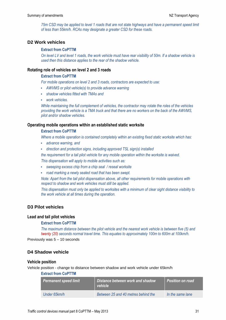
75m CSD may be applied to level 1 roads that are not state highways and have a permanent speed limit of less than 55km/h. RCAs may designate a greater CSD for these roads.
D2 Work vehicles
Extract from CoPTTM
On level LV and level 1 roads, the work vehicle must have rear visibility of 50m. If a shadow vehicle is used then this distance applies to the rear of the shadow vehicle.
Rotating role of vehicles on level 2 and 3 roads
Extract from CoPTTM
For mobile operations on level 2 and 3 roads, contractors are expected to use:
• AWVMS or pilot vehicle(s) to provide advance warning
• shadow vehicles fitted with TMAs and
• work vehicles.
While maintaining the full complement of vehicles, the contractor may rotate the roles of the vehicles providing the work vehicle is a TMA truck and that there are no workers on the back of the AWVMS, pilot and/or shadow vehicles.
Operating mobile operations within an established static worksite
Extract from CoPTTM
Where a mobile operation is contained completely within an existing fixed static worksite which has:
• advance warning, and
• direction and protection signs, including approved TSL sign(s) installed
the requirement for a tail pilot vehicle for any mobile operation within the worksite is waived.
This dispensation will apply to mobile activities such as:
• sweeping excess chip from a chip seal / reseal worksite
• road marking a newly sealed road that has been swept.
Note: Apart from the tail pilot dispensation above, all other requirements for mobile operations with respect to shadow and work vehicles must still be applied.
This dispensation must only be applied to worksites with a minimum of clear sight distance visibility to the work vehicle at all times during the operation.
D3 Pilot vehicles
Lead and tail pilot vehicles
Extract from CoPTTM
The maximum distance between the pilot vehicle and the nearest work vehicle is between five (5) and twenty (20) seconds normal travel time. This equates to approximately 100m to 600m at 100km/h.
Previously was 5 – 10 seconds
D4 Shadow vehicle
Vehicle position
Vehicle position - change to distance between shadow and work vehicle under 65km/h
Extract from CoPTTM
Permanent speed limit Distance between work and shadow
vehicle
Position on road
Under 65km/h Between 25 and 40 metres behind the In the same lane
Summary of amendments NZ Transport Agency
Traffic control devices manual part 8 CoPTTM – May 2013 32
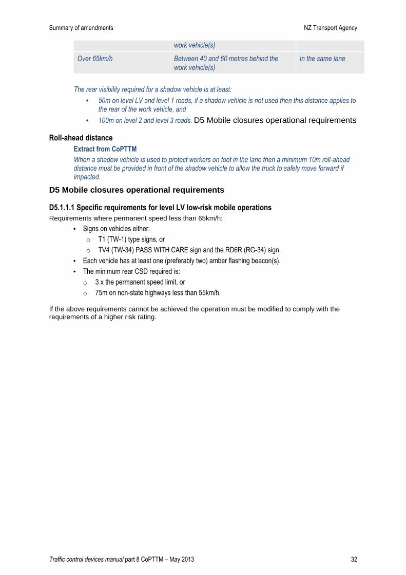
work vehicle(s)
Over 65km/h Between 40 and 60 metres behind the
work vehicle(s)
In the same lane
The rear visibility required for a shadow vehicle is at least:
• 50m on level LV and level 1 roads, if a shadow vehicle is not used then this distance applies to the rear of the work vehicle, and
• 100m on level 2 and level 3 roads. D5 Mobile closures operational requirements
Roll-ahead distance
Extract from CoPTTM
When a shadow vehicle is used to protect workers on foot in the lane then a minimum 10m roll-ahead distance must be provided in front of the shadow vehicle to allow the truck to safely move forward if impacted.
D5 Mobile closures operational requirements
D5.1.1.1 Specific requirements for level LV low-risk mobile operations
Requirements where permanent speed less than 65km/h:
• Signs on vehicles either:
o T1 (TW-1) type signs, or
o TV4 (TW-34) PASS WITH CARE sign and the RD6R (RG-34) sign.
• Each vehicle has at least one (preferably two) amber flashing beacon(s).
• The minimum rear CSD required is:
o 3 x the permanent speed limit, or
o 75m on non-state highways less than 55km/h.
If the above requirements cannot be achieved the operation must be modified to comply with the requirements of a higher risk rating.
Summary of amendments NZ Transport Agency
Traffic control devices manual part 8 CoPTTM – May 2013 33
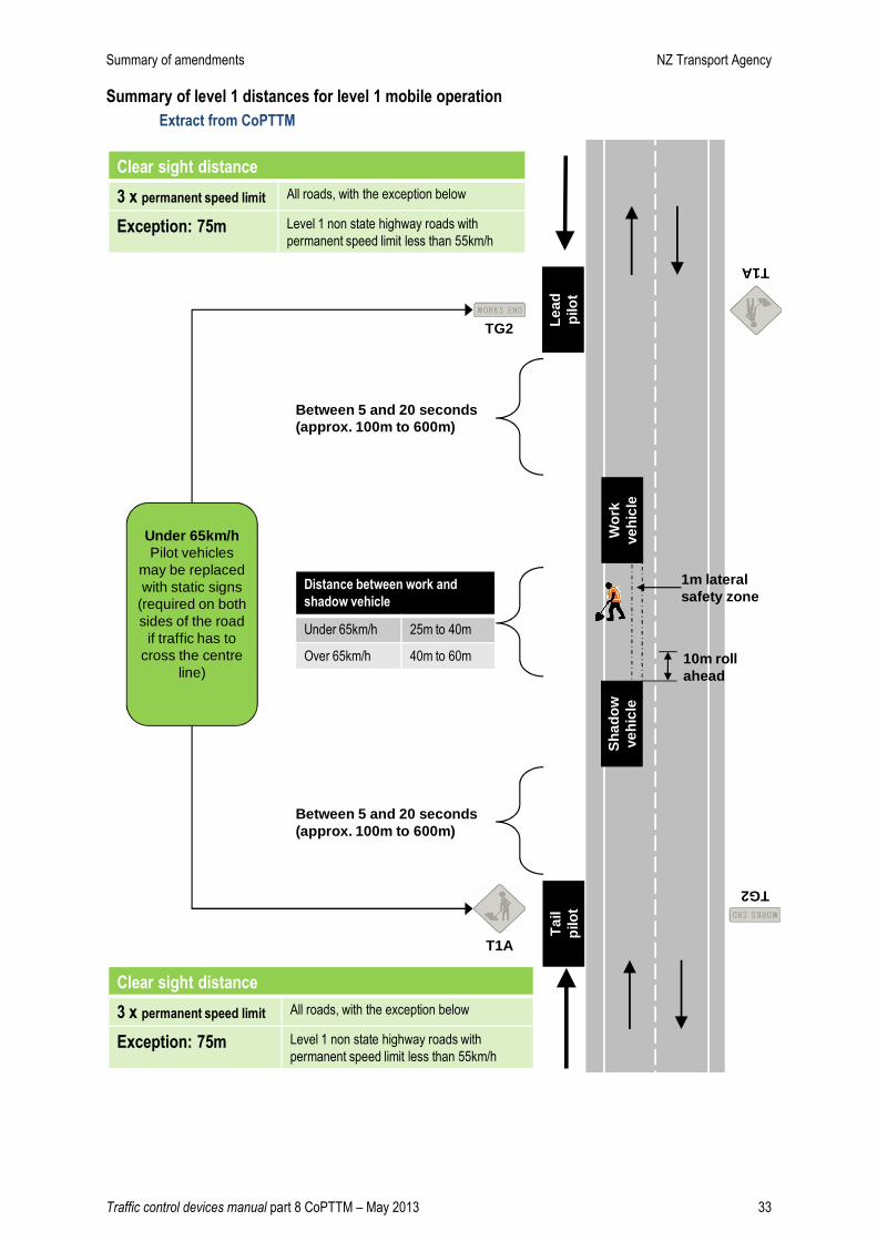
Summary of level 1 distances for level 1 mobile operation
Extract from CoPTTM
Between 5 and 20 seconds (approx. 100m to 600m)
Clear sight distance
3 x permanent speed limit All roads, with the exception below
Exception: 75m Level 1 non state highway roads with
permanent speed limit less than 55km/h
Distance between work and
shadow vehicle
Under 65km/h 25m to 40m
Over 65km/h 40m to 60m 10m roll ahead
Clear sight distance
3 x permanent speed limit All roads, with the exception below
Exception: 75m Level 1 non state highway roads with
permanent speed limit less than 55km/h
Between 5 and 20 seconds (approx. 100m to 600m)
1m lateral safety zone
Wor
k ve
hicl
e
Lead
pi
lot
Sha
dow
ve
hicl
e
Tai
lpi
lot
Under 65km/h Pilot vehicles
may be replaced with static signs
(required on both sides of the road
if traffic has to cross the centre
line)
T1A
TG2
T1A
TG2
Summary of amendments NZ Transport Agency
Traffic control devices manual part 8 CoPTTM – May 2013 34
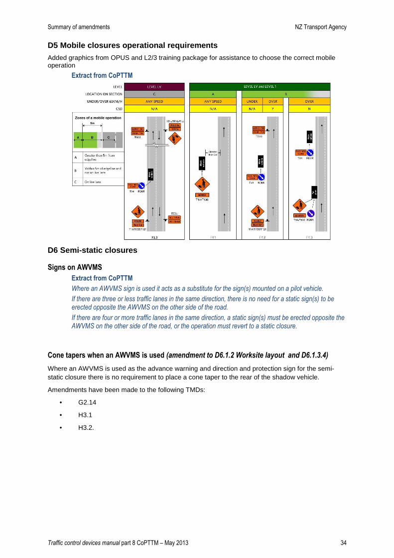
D5 Mobile closures operational requirements
Added graphics from OPUS and L2/3 training package for assistance to choose the correct mobile operation
Extract from CoPTTM
D6 Semi-static closures
Signs on AWVMS
Extract from CoPTTM
Where an AWVMS sign is used it acts as a substitute for the sign(s) mounted on a pilot vehicle.
If there are three or less traffic lanes in the same direction, there is no need for a static sign(s) to be erected opposite the AWVMS on the other side of the road.
If there are four or more traffic lanes in the same direction, a static sign(s) must be erected opposite the AWVMS on the other side of the road, or the operation must revert to a static closure.
Cone tapers when an AWVMS is used (amendment to D6.1.2 Worksite layout and D6.1.3.4)
Where an AWVMS is used as the advance warning and direction and protection sign for the semi-static closure there is no requirement to place a cone taper to the rear of the shadow vehicle.
Amendments have been made to the following TMDs:
• G2.14
• H3.1
• H3.2.
Summary of amendments NZ Transport Agency
Traffic control devices manual part 8 CoPTTM – May 2013 35
D7 Special activities
Road marking
Extract from CoPTTM
To assist with TTM for road marking operations some industry best practice TMPs have been prepared and are available in section I.2 of CoPTTM
New requirements for kerbside collections
Kerbside collections industry have developed a set of requirements that have been agreed with NZTA.
Repairing a flexible median barrier
Requirements added for repairing a flexible median barrier
Rolling blocks
Requirements added for rolling blocks
Summary of amendments NZ Transport Agency
Traffic control devices manual part 8 CoPTTM – May 2013 36
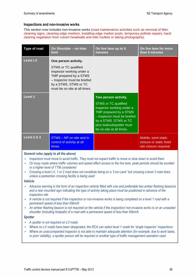
Inspections and non-invasive works
This section now includes non-invasive works (road maintenance activities such as removal of litter, cleaning signs, cleaning edge markers, installing edge marker posts, temporary pothole repairs, hand clearing vegetation from culvert headwalls and inlet /outlets or taking photographs).
Type of road On Shoulder – no time limit
On live lane up to 5 minutes
On live lane for more than 5 minutes
Level LV One person activity.
STMS or TC qualified inspector working under a TMP prepared by a STMS – Inspector must be briefed by a STMS. STMS or TC must be on site at all times.
Level 1
Two person activity.
STMS or TC qualified inspector working under a TMP prepared by a STMS – Inspector must be briefed by a STMS. STMS or TC plus lookout/spotter must be on-site at all times.
Level 2 & 3 STMS – NP on site and in control of activity at all times.
Mobile, semi-static closure or static fixed site closure required.
General rules (apply to all the above)
• Inspectors must move to avoid traffic. They must not expect traffic to move or slow down to avoid them
• On busy roads where traffic volumes and speed affect access to the live lane, peak periods should be avoided or a higher level of TTM considered
• Crossing a level LV, 1 or 2 road does not constitute being on a “Live Lane” but crossing a level 3 road does, unless a pedestrian crossing facility is being used
Vehicle
• Advance warning in the form of an inspection vehicle fitted with one and preferable two amber flashing beacons and a rear mounted sign indicating the type of activity taking place must be positioned in advance of the inspection site
• A vehicle is not required if the inspection or non-invasive works is being completed on a level 1 road with a permanent speed of less than 65km/h
• An amber flashing beacon is not required on the vehicle if the inspection/ non-invasive works is on an unsealed shoulder (including footpath) of a road with a permanent speed of less than 65km/h
Spotter
• A spotter is not required on LV roads
• Where no LV roads have been designated, the RCA can select level 1 roads for ‘single inspector’ inspections
• Where an unaccompanied inspector is not able to maintain adequate attention (for example, due to work tasks,
or poor visibility), a spotter person will be required or another type of traffic management operation used
Summary of amendments NZ Transport Agency
Traffic control devices manual part 8 CoPTTM – May 2013 37
Section E – Standard forms and descriptions
TMP forms
There are new TMP forms for:
• Short TMP
• Full TMP.
The onsite record (or company equivalent) needs to be completed for every site.
Audit forms
There is a new full audit from and a short audit form that may be used by some RCAs