Embed Size (px)
Citation preview
OCS ReportMMS 2001-067
Brief Overview of Gulf of Mexico OCSOil and Gas Pipelines: Installation,Potential Impacts, and Mitigation Measures
U.S. Department of the InteriorMinerals Management ServiceGulf of Mexico OCS Region

U.S. Department of the InteriorMinerals Management ServiceGulf of Mexico OCS Region
OCS ReportMMS 2001-067
Brief Overview of Gulf of Mexico OCSOil and Gas Pipelines: Installation,Potential Impacts, and Mitigation Measures
Author
Deborah CranswickMinerals Management ServiceGulf of Mexico OCS Region
Published by
New OrleansAugust 2001

Brief Overview of Gulf of Mexico OCSOil and Gas Pipelines: Installation,
Potential Impacts, and Mitigation Measures
Introduction
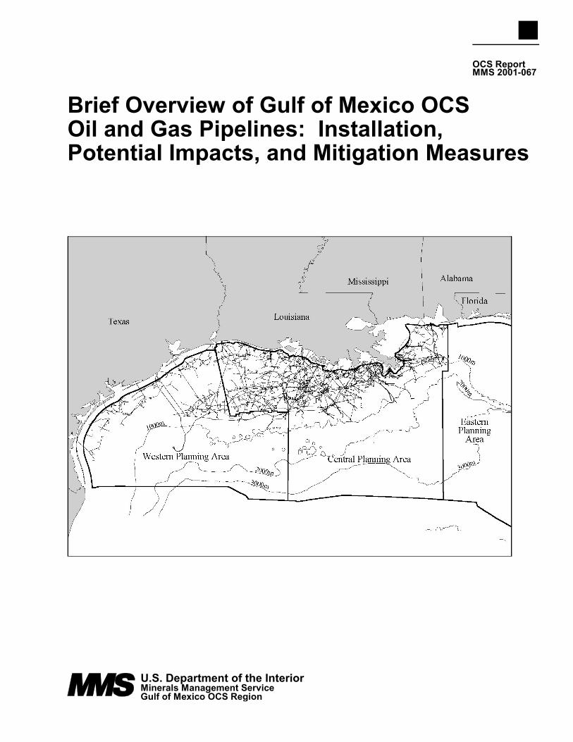
The ability to transport produced hydrocarbons has always been an important factor in thesuccessful development of an oil or natural gas field, both onshore and offshore. Historically,pipelines have been the most common means used to transport crude oil produced in the Gulf ofMexico (GOM) Outer Continental Shelf (OCS). The technology and methods involved in pipelinetransport of product from offshore oil and gas fields located in the shallower waters of the Gulf ofMexico OCS have evolved to the level of routine and commonplace. Much of the same technologyand methods would be employed in the deep waters beyond the edge of the continental slope;however, the operating environment for deepwater pipelines differs from the operating environmentof pipelines on the shelf. The current extent of oil pipeline infrastructure in the GOM is shown onFigure 1. As of June 2001, there were approximately 44,218 km (27,569 mi) of pipeline on theseafloor of the GOM. Most of these pipelines support shelf and near-shelf facilities; a smallpercentage supports deepwater operations.
This paper presents a general summary of pipeline information and issues in the Gulf of Mexico.The collected information is not intended as an in-depth review of pipeline activities and issues, butrather general information for decisionmakers, regulatory agencies, and other interested parties. Thispaper has also been prepared to serve as a general reference document for environmental assessmentsprepared on specific pipeline applications.
Pipelines in the Gulf are designated as either gathering lines or trunklines. Gathering lines aretypically shorter segments of small-diameter pipelines that transport materials from one or morewells to a production facility or from a production facility to a trunkline. Trunklines are typicallylarge-diameter pipelines that transport produced oil or gas to shore. A trunkline may carryproduction from many wells and from several hydrocarbon fields, leases, or blocks. The OCS-related pipelines near shore and onshore may join pipelines carrying production from State watersor territories for transport to processing facilities or distribution pipelines located farther inland.
Product stream quality, available pipeline capacity, and existing infrastructure are factorsinfluencing the potential need for additional pipelines. Factors such as the aging condition ofexisting pipeline systems and existing systems operating at or near capacity in the GOM, combinedwith the projected production from new developments, indicate the need for future enhancement andexpansion of the existing pipeline system. An alternative to installing new pipelines is to increasethe carrying capacity of the existing pipeline system to accommodate new production fromdeepwater areas. One method for achieving additional carrying capacity for existing pipelines isincreasing the maximum allowable operating pressure (MAOP) within a pipeline.
Regulatory Framework
Regulatory processes and jurisdictional authority concerning pipelines on the OCS and in coastalareas are shared by several Federal agencies, including the Department of the Interior (DOI),Department of Transportation (DOT), U. S. Army Corps of Engineers (USCOE), the Federal EnergyRegulatory Commission (FERC), and the U.S. Coast Guard (USCG). These agencies also haveresponsibility for overseeing and regulating the placement of structures on the OCS and pipelinesin areas that affect navigation, and the certification of proposed projects involving the transportation
or sale of interstate natural gas, including OCS gas. In addition, DOT is responsible for regulatingthe safety of interstate commerce of natural gas, liquefied natural gas (LNG), and hazardous liquidsby pipeline. This responsibility includes all offshore pipelines on State lands beneath navigablewaters and on the OCS. The regulations are contained in 49 CFR 191 through 193 and 195. In aMemorandum of Understanding (MOU) between DOT and DOI dated December 10, 1996, eachparty’s respective regulatory responsibilities are outlined. The DOT is responsible for establishingand enforcing design, construction, operation, and maintenance regulations, and for investigatingaccidents for all OCS transportation pipelines beginning downstream of the point at which operatingresponsibility transfers from a producing operator to a transporting operator. The DOI’sresponsibility extends upstream from the transfer point described above.
The MMS is responsible for regulatory oversight of the design, installation, and maintenance ofOCS oil and gas pipelines. The MMS operating regulations for pipelines found at 30 CFR 250Subpart J are intended to provide safe and pollution-free transportation of fluids in a manner thatdoes not unduly interfere with other users of the OCS. Pipeline applications are usually submittedand reviewed separately from development and production plans. Pipeline applications may be foron-lease pipelines or right-of-way for pipelines that cross other lessees’ leases or unleased areas ofthe OCS. Pipeline permit applications to MMS include the pipeline location drawing, profiledrawing, safety schematic drawing, pipe design data to scale, a shallow hazard survey report, andan archaeological report (if required).
The MMS evaluates the design, fabrication, installation, and maintenance of pipelines. Proposedpipeline routes are evaluated for potential seafloor or subsea geologic hazards and other natural ormanmade seafloor or subsurface features or conditions (including other pipelines) that could havean adverse impact on the pipeline or that could be adversely impacted by the proposed operations.Routes are also evaluated for potential impacts on archaeological resources and biologicalcommunities. A categorical exclusion review (CER), environmental assessment (EA), and/orenvironmental impact statement (EIS) is prepared in accordance with applicable policies andguidelines. The MMS prepares an EA and/or an EIS on all pipeline rights-of-way that go ashore.No pipeline route will be approved by MMS if any bottom-disturbing activities (from the pipelineitself or from the anchors of lay barges and support vessels) encroach on any biologically sensitiveareas.
The design of the proposed pipeline is evaluated for:
• Appropriate cathodic protection system to protect the pipeline from leaks resultingfrom the effects of external corrosion of the pipe;
• External pipeline coating system to prolong the service life of the pipeline;• Measures to protect the inside of the pipeline from the detrimental effects, if any, of
the fluids being transported;• Submersibility of the pipeline(that is, that the pipeline will remain in place on the
seafloor and not float, even if empty or filled with gas rather than liquids);• Proposed operating pressures;• Adequate provisions to protect other pipelines the proposed route crosses over; and• Compliance with all applicable regulations.
The evaluation includes reviewing the calculations used by the applicant in order to determinewhether the applicant properly considered all of the critical elements. Such elements include thegrade of pipe, the wall thickness of the pipe, the pressure rating of any valves or flanges, the pressurerating of any other pipeline(s) into which the proposed line might be tied, the required testingpressures, and the type and placement of protective devices. Devices, such as pressure sensors andremotely operated valves, are intended to protect the pipeline from possible overpressure conditionsand to detect and initiate a response to abnormally low-pressure conditions.
According to MMS regulations (30 CFR 250.1003(a)(1)), pipelines with diameters ≥85/8 inchesthat are installed in water depths <200 ft are to be buried to a depth of at least 3 ft below the mudline.The regulations also provide for the burial of any pipeline, regardless of size, if the MMS determinesthat the pipeline may constitute a hazard to other uses of the OCS; in the GOM, the MMS hasdetermined that all pipelines installed in water depths <200 ft must be buried. The purpose of theserequirements is to reduce the movement of pipelines by high currents and storms, to protect thepipeline from the external damage that could result from anchors and fishing gear, to reduce the riskof fishing gear becoming snagged, and to minimize interference with the operations of other usersof the OCS. For lines 85/8 inches and smaller, a waiver of the burial requirement may be requestedand may be approved if the line is to be laid in an area where the character of the seafloor will allowthe weight of the line to cause it to sink into the sediments (self-burial). For water depths ≤200 ft,any length of pipeline that crosses a fairway or anchorage in Federal waters must be buried to aminimum depth of 10 ft below mudline across a fairway and a minimum depth of 16 ft belowmudline across an anchorage area. Some operators voluntarily bury these pipelines deeper than theminimum.
Operators are required to inspect pipeline routes periodically. Monthly overflights are conductedto inspect pipeline routes for leakage.
Applications for pipeline abandonment must also be submitted for MMS review and approval.Abandonment applications are evaluated to ensure they will render the pipeline inert and/or tominimize the potential for pollution by flushing the pipeline and filling it with seawater. Tominimize the potential for the abandoned line to become an obstruction to other users of the OCS,operators are required to plug and bury the ends of abandoned pipelines.
Pipeline Installation
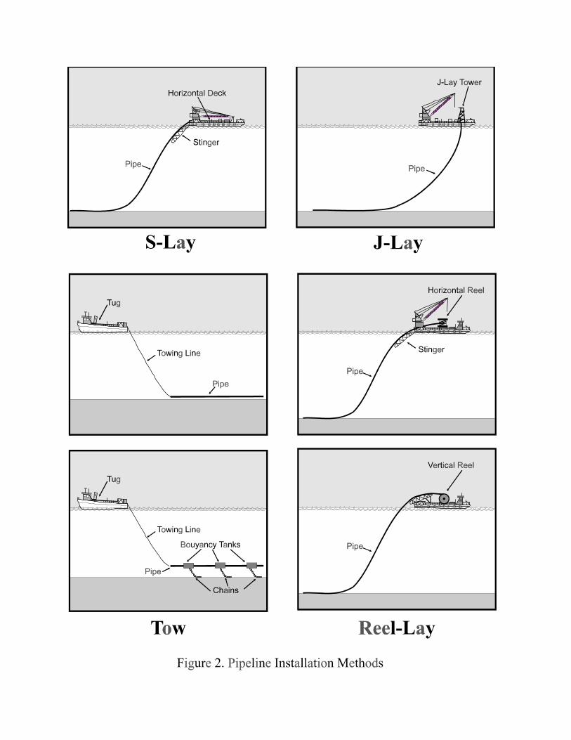
S-Lay Method
The traditional method for installing offshore pipelines in relatively shallow water is commonlyreferred to as the S-lay method because the profile of the pipe as it moves in a horizontal plane fromthe welding and inspection stations on the lay barge across the stern of the lay barge and on to theocean floor forms an elongated “S” (Figure 2). As the pipeline moves across the stern of the laybarge and before it reaches the ocean floor, the pipe is supported by a stinger – a truss-like structureis equipped with rollers and is known as a stinger. The purpose of a stinger is to minimize curvature,and therefore the bending stress, of the pipe as it leaves the vessel.
In extremely deep water, the angle of the pipe becomes so steep that the required stinger lengthmay not be feasible. Deeper water depths will result in a steeper lift-off angle of the suspended pipespan at the stinger tip, requiring the stinger to be longer and/or more curved to accommodate thegreater arc of reverse curvature in the overbend region. Accordingly, greater stinger buoyancy and/orstructural strength will be necessary to support the increased weight of the suspended pipe span.
J-Lay Method
A comparatively new method for installing offshore pipelines in deeper water is the J-laymethod. The method was so-named because the configuration of the pipe as it is being assembledresembles a “J”(Figure 2). Lengths of pipe are joined to each other by welding or other means whilesupported in a vertical or near-vertical position by a tower, and as more pipe lengths are added to thestring, the string is lowered to the ocean floor. The J-lay method is inherently slower than the S-laymethod and is, therefore, more costly.
The J-lay pipelaying technique represents a logical extension of the industry’s capability intodeepwater. The J-lay method offers an alternative to the conventional lay barge in that the stingerrequirements for deepwater are greatly reduced. The purpose of a stinger in the J-lay configurationsis to change the angle at the top of the pipeline to a vertical orientation. As seen in Figure 2, theorientation of the pipeline at the surface have a large bend. The benefits of this method are that thebending stresses are low, the horizontal force required for station keeping is within the capability ofdynamic positioning systems, and the use of modular towers allows derrick barges and moderatelysized support vessels to be equipped for pipeline installations.
The J-lay method is difficult to use in water depths as shallow as 200-500 ft because of limitedpipe angle and the bending stress imposed on the pipe. Conventionally moored lay barges are notnormally used for J-lay pipeline installations in this water depth because of the required tension onanchors and pipe bending stress.
Reel Method
For pipeline installation by reel ship (Figure 2), the pipe is welded, coated with a resilientprotective coating (flexible epoxy or polyethylene jacket), and spooled onto a large diameter reelwhile at the land base. After the pipe is loaded onto the reel, the ship proceeds to the pipelaying area.The pipe is fed off of the reel, straightened, deovalized, and then anchored, if necessary, to theseabed. In deepwater, the pipe has to be tensioned. As the pipe stretches from the sea surface to theseabed, a large sag forms in the pipe. If the sag bend becomes too great, the pipe will buckle.Tensioning the pipe minimizes the amount of sag. The amount of tension necessary is dependenton the depth of water, the axial strength of the pipe, the allowable stresses for the particular pipe, andthe capacity of the tensioning winches. After the pipe has been anchored and tensioned, the shipproceeds ahead slowly reeling out the pipe. This is usually done at about one knot depending onweather conditions. When the reel has been emptied, a bull plug is welded onto the end of the pipeand an abandonment cable attached. This is played out under tension until the pipe rests on theseabed. Then a buoy is attached to the end of the cable. The ship then proceeds to port to replenishthe reel or take on a fully loaded new reel.
The diameter of the pipe that can be spooled onto the reel is restricted by the size of the reel.Pipe installed by this method cannot be “weight coated” because the coating would be destroyed bythe bending inherent in this installation method. Instead, thick-walled pipe is used to achieve therequired negative buoyancy.
Reel barges are currently divided into two classes – horizontal reel and vertical reel. For ahorizontal reel, the axis of rotation is vertical with respect to the barge deck. For a vertical reel, theaxis of rotation is horizontal. The vertical reel barge is versatile and can lay pipe in shallow wateras well as in very deepwater. This method minimizes bending stresses in the overbend region. Ifthe reel is bottom-loaded, the pipe is fed out horizontally making it well suited for shallow-waterwork. For deepwater pipelaying, the reel is top-loaded and the pipe is discharged vertically after itis straightened. For intermediate depths, the angle of entry can be adjusted in consideration ofengineering calculations and judgments. Since bending stresses are minimized by the vertical reelmethod, a stinger is not needed. For the horizontal reel method, a stinger is needed in other thanshallow-water pipelaying operations.
The greatest advantage of the reel method is the speed with which the line can be laid. Thisgreater speed permits laying miles of pipe during a fairly short weather window and extending theconventional construction season (spring through fall) by several months. Since no on-boardwelding is required, some reel barges can lay the same length of pipe in a few hours that would takea lay barge a full day to lay. Additionally, the quality of the pipeline construction is enhanced bywelding and x-ray inspection performed under controlled conditions onshore. Deepwater pipelayingby vertical reel is simplified by the elimination of the need for a stinger. The principal disadvantage
of this method is the difficulty of connecting the ends of the pipeline segments. The re-reeling andremoving of a buckle during pipelaying operations can also be particularly time-consuming. Forpipelines being laid far offshore or a long distance from a supply base, a great deal of time is spentin transit to and from port or the pipeline support base.
Bottom Tow Method
A fourth, but less commonly used, method of constructing and installing offshore pipelines isthe bottom tow (Figure 2). This method involves onshore fabrication and assembly of the pipeline,that is, welding, inspection, joint-coating, and anode installation. (For S-lay and J-lay operations,these tasks are normally carried out on the lay barge immediately prior to the pipeline going into thewater.) The assembled pipe is then towed from the onshore location to its designated position byseagoing vessels. The pipeline is towed on or near the seafloor along a route that was pre-surveyedto identify any potential seafloor hazards. The assembled pipe can be towed either as an individualpipeline or as a bundle of several pipelines. This method of installation is particularly well-suitedto pipe-in-pipe flowline assemblies, which can be more efficiently fabricated onshore and whichcontain thermal insulation in the annular space between the inner and outer pipes. Such insulatedpipe-in-pipe flowline assemblies are necessary to maintain the temperature of the produced fluidsduring transport through the very cold water of the deep Gulf of Mexico. A limitation of thisinstallation method is the increased risk that the pipeline could be damaged during the tow throughcontact with a subsea obstruction. Such damage could result in potentially catastrophicconsequences if the integrity of the outer pipe were compromised, resulting in the exposure of thethermal insulation to the subsea environment.
Conventionally Moored Lay Barges/Vessels
The term “conventionally moored” means that the location or position of the pipeline installationvessel (lay barge) is maintained through anchors, associated anchor chains, and/or cables. Smallerlay barges, in the 400-ft long by 100-ft wide size range, typically require 8 anchors weighing 30,000lbs each; and a larger barge operating in 1,000 ft of water typically requires 12 anchors (3 anchorsper quarter), each weighing 50,000 lbs or more.
The relationship between the size of a vessel and the size of the anchors required for holding thevessel on-station is not a function of the pipeline installation method being used; it is a function ofthe size of the lay barge. In general, the larger the vessel (that is, the greater the target area presentedto wind, wave, and current forces, and the heavier the vessel), the higher the holding requirementswill be for the mooring system. The rated holding capacity of an anchor system is a function of theweight and size of the anchor, and the tensile strength of the chain or cable that secure the anchorto the vessel. The number of anchors used by a conventionally moored lay barge for S-lay and J-layoperation is very similar: 8 to 12 anchors, depending on lay barge size.
An important factor to be considered when there is a choice to be made between a conventionallymoored lay barge and a lay barge that uses other means, such as dynamic positioning, to remain on-station is the matter of handling the anchors. To deploy and recover the anchors of a S-lay bargeoperating in 1,000 ft of water, two anchor handling vessels with a power rating of 8,000-10,000horsepower (HP) each would be required, and there is a shortage of such vessels. On the other hand,a smaller lay barge operating in shallower water requires only one 3,000-5,000 HP anchor-handlingvessel. The number of anchor-handling vessels associated with a J-lay barge would be essentiallythe same as for a similar size barge using the S-lay method.
The number of anchor relocations per mile of offshore pipeline constructed is a function of thesize of the lay barge, water depth, ocean floor conditions in the vicinity of the pipeline installation,and the amount of anchor line that can be stored, deployed, and retrieved by the lay barge. Assuming
a lay barge is operating in 1,000 ft of water and is following the accepted practice of deploying anamount of anchor line equal to five times the water depth, the anchors would have to be relocatedafter each 2,000 ft of pipeline installed. The number of anchor relocations per mile of pipelineinstalled by a conventionally moored lay barge would be similar for the S-lay and the J-lay methods.
The practical water depth limit for a large conventionally moored lay barge that uses the S-laymethod is about 1,000 ft, based on a ratio of anchor line length to water depth of about 5 to 1. Forpipelines supporting deepwater production facilities, installation by conventionally moored laybarges will probably be limited to those portions of the pipeline routes located in water depths lessthan 1,000 ft.
Dynamically Positioned Lay Barges/Vessels
The term “dynamically positioned” means that the location or position of the lay barge ismaintained by the vessel’s very specialized propulsion/station-keeping system which, instead of orin addition to the conventional propeller-rudder system at the stern, employs a system of hull-mounted thrusters near the bow, at mid-ship, and at the stern. When in the station-keeping mode,these thrusters, which have the capability to rotate 360o in a horizontal plane, are controlled by ashipboard computer system that usually interfaces with a satellite-based geographic positioningsystem.
Dynamic positioning of lay barges can be used in water depths as shallow as 100 ft, but generallyit is not used in water less than 200 ft. The minimum water depth at which dynamically positionedlay barges are believed to have an economic advantage over conventionally moored lay barges isabout 600 ft. Dynamically positioned lay barges outfitted with the equipment necessary to installreel pipe are sometimes used in shallow water.
Emissions
Potential emissions is one of the most significant differences between a dynamically positionedlay barge and a conventionally moored lay barge. For a conventionally moored vessel, the mainpropulsion system is typically shut down or operating at minimum speed, fuel consumption, andemission levels while the vessel is not under way (during actual pipeline installation).Conventionally moored lay barges typically require the assistance of other vessels to move fromstation-to-station and to deploy and recover anchors. Dynamically positioned lay barges requireadditional and larger engines for thrust control. A typical dynamically positioned vessel system hassix fully retractable, azimuthing, 1,000-1,500 horsepower thrusters, plus a second engine room forthe generation of electrical power. The emissions that are generated from dynamically positionedlay barges can equal the emissions of a drillship as compared with the emissions of conventionallymoored lay barges. The increased emissions from dynamically positioned vessel operations oftenlead to a temporary decrease in air quality.
Pipeline Burial
Use of a jetting sled is one typical method of burying pipelines. Jetting sleds are mounted withhigh-pressure water jets and pulled along the seafloor behind the pipelaying barge. The water jetsare directed downward to dig a trench; the sled guides the pipeline into the trench. Such anapparatus can lay pipe at an average of 1.6 km/day. The cross section of a typical jetted trench forthe flowline bundles would be about 3.77 m2; for deeper burial crossing a fairway, the cross sectionwould be about 12.83 m2. The cross section of a typical jetted trench for the export andinterconnecting export pipelines would be about 5.02 m2; for a pipeline trench crossing a fairway,the cross section would be about 14.51 m2.
Jetting disperses sediments over the otherwise undisturbed water bottom that flanks the jettedtrench. The area covered by settled sediment and the thickness of the settled sediment depends uponvariations in bottom topography, sediment density, and currents.
Operating Conditions
The operating environment for pipelines is notably different in shallow water and deepwater.Compared with shallow-water pipelines, pipelines located in deepwater endure:
• greater physical stresses (for example, extreme depths and strong currents) on thepipe and equipment during installation;
• higher hydrostatic pressures (that is, water pressure at depth); and• colder water and sediment temperatures.
To date, approximately 54 percent of the deepwater fields have been developed using subseacompletions. The produced hydrocarbon fluids are typically conveyed via multiphase (oil, gas,condensate, and water) flowlines and pipelines to a host facility.
Pipeline installation activities in deepwater areas can be difficult both in terms of route selectionand construction. Depending on the location, the sea bottom surface can be extremely irregular andpresent engineering challenges (for example, high hydrostatic pressure, cold temperatures, anddarkness, as well as varying subsurface current velocities and directions). Rugged seafloor maycause terrain-induced pressures within the pipe that can be operationally problematic, as the oil mustbe pumped up and down steep slopes. An uneven seafloor could result in unacceptably long lengthsof unsupported pipeline, referred to as “spanning,” which in turn could lead to pipe failure frombending stress early in the life of the line. It is important to identify areas where significant lengthsof pipeline may go unsupported. Accurate, high-resolution geophysical surveying becomesincreasingly important in areas with irregular seafloor. Recent advances in surveying techniques havesignificantly improved the capabilities for accurately defining seafloor conditions, providing theresolution needed to determine areas where pipeline spans may occur. After analyzing survey data,the operator chooses a route that minimizes pipeline length and avoids areas of seafloor geologicstructures and obstructions that might cause excessive pipe spanning, unstable seafloor, and potentialbenthic communities.
The greater pressures and colder temperatures in deepwater present difficulties with respect tomaintaining the flow of crude oil through pipelines. Under these conditions, the physical andchemical characteristics of the produced hydrocarbons can lead to the accumulation of gas hydrate,paraffin, and other substances within the pipeline. These accumulations can restrict and eventuallyblock flow if not successfully prevented and/or abated. There are physical and chemical techniquesthat can be applied to manage these potential accumulations. The leading strategy to mitigate thesedeleterious effects is to minimize heat loss from the system by using insulation. Other measuresinclude forcing plunger-like “pigging” devices through the pipeline to scrape the pipe walls clean,and the continuous injection of flow-assurance chemicals (e.g., methanol or ethylene glycol) into thepipeline system to minimize the formation of flow-inhibiting substances. However, the great waterdepths of the OCS and the extreme distance to shoreside facilities make these flow-assurancemeasures difficult to implement and can significantly increase the cost to produce and transport theproduct. Installation of pipelines for transmission of natural gas in deepwater is usually morefeasible than for oil pipelines. Natural gas pipelines are of a smaller diameter, weigh less, andinstallation is less complicated. Additionally, the flow assurance issues associated with oil pipelinesare not applicable to the transmission of processed natural gas.
Long distance production of multiphase wellstream fluids can be achieved with an effectivelyinsulated flowline. There are three major categories of insulation systems: pipe-in-pipe systems,
integrated towed flowline bundles, and non-jacketed systems. The design of all of these systemsseeks a balance between the high cost of the insulation, the intended operability of the system, andthe acceptable risk level. Such a system minimizes the costs, revenue loss, and risks from thefollowing:
• hydrate formation during steady state or transient flowing conditions;• paraffin accumulation on the inner pipe wall that can result in flowline plugging or
flow rate reductions;• adverse fluid viscosity effects at low temperatures that lead to reduced hydraulic
performance or to difficulties restarting a cooled system after a short shut-in; and• additional surface processing facilities required to heat produced fluids to aid in the
separation processes.
Design criteria should require pipelines that can be safely placed on the seabed in water depthsof 400 meters or more. The temperature range of the produced oil and gas can be expected to be amaximum of 110 o C; therefore, the system should be based on a 120 o C maximum operatingtemperature. It is also desirable for the design of the system to fit all laying methods.Simultaneously, the stringent requirements for the integrity of field joints (the welded connectionsthat join together lengths of pipe, so-named because they are typically made in the field aboard thelay barge) must be maintained. Even for thick and well-sealed insulating systems, the corrosionprotection for the steel surface must be adequate.
Gas hydrate formation during deepwater drilling is a well-recognized and potentially hazardousoperational problem in water depths greater than 1,000 ft (300 m). Seabed conditions of highpressure and low temperature become conducive to gas hydrate formation in deepwater. Gashydrates are ice-like crystalline solids formed by low-molecular-weight hydrocarbon gas molecules(mostly methane) combining with water. The formation of gas hydrates is potentially hazardousbecause hydrates can restrict or even completely block fluid flow in a pipeline, resulting in a possibleoverpressure condition. The interaction between the water and gas is physical in nature and is nota chemical bond. Gas hydrates are formed and remain stable over a limited range of temperaturesand pressures.
Hydrate prevention is normally accomplished through the use of methanol, ethylene glycol, ortri-ethylene glycol as inhibitors, and the use of insulated flowlines and risers. Chemical injectionis sometimes provided both at the wellhead and at a location within the well just above thesubsurface safety valve. Wells that have the potential for hydrate formation can be treated witheither continuous chemical injection or intermittent or “batch” injection. In many cases, batchtreatment is sufficient to maintain well flow. In such cases, it is necessary only to inject inhibitorat well start-up, and the well will continue flowing without the need for further treatment. In theevent that a hydrate plug should form in a well that is not being injected with a chemical, theremediation process would be to depressurize the flowlines and inject the chemical. Hydrateformation within a gas sales line can be eliminated by dehydrating the gas with a glycol dehydratingsystem prior to input of gas into the sales line. In the future, molecular sieve and membraneprocesses may also be options for dehydrating gas. Monitoring of the dewpoint downstream of thedehydration tower should take place on a continuous basis. In the event that the dehydrationequipment is bypassed because it may be temporarily out of service, a chemical could be injectedto help prevent the formation of hydrates if the gas purchaser agrees to this arrangement beforehand.
Hydrocarbon flows that contain paraffin or asphaltenes may occlude pipelines as thesesubstances, which have relatively low melting points, form deposits on the interior walls of the pipe.To help ensure product flow under these conditions, an analysis should be made to determine thecloud point and hydrate formation point during normal production temperatures and pressures. Tominimize the formation of paraffin or hydrate depositions, wells can be equipped with a chemical
injection system. If, despite treatment within the well, it still becomes necessary to inhibit theformation of paraffin in a pipeline, this can be accomplished through the injection of a solvent suchas diesel fuel into the pipeline.
Pigging is a term used to describe a mechanical method of displacing a liquid in a pipeline or toclean accumulated paraffin from the interior of the pipeline by using a mechanized plunger or “pig.”Paraffin is a waxy substance associated with some types of liquid hydrocarbon production. Thephysical properties of paraffin are dependent on the composition of the associated crude oil, andtemperature and pressure. At atmospheric pressure, paraffin is typically a semi-solid at temperaturesabove about 100 o F and will solidify at about 50 o F. Paraffin deposits will form inside pipelines thattransport liquid hydrocarbons and, if some remedial action, such as pigging, is not taken, thedeposited paraffin will eventually completely block all fluid flow through the line. The piggingmethod involves moving a pipeline pig through the pipeline to be cleaned. Pipeline pigs areavailable in various shapes and are made of various materials, depending on the pigging task to beaccomplished. A pipeline pig can be a disc or a spherical or cylindrical device made of a pliablematerial such as neoprene rubber and having an outside diameter nearly equal to the inside diameterof the pipeline to be cleaned. The movement of the pig through the pipeline is accomplished byapplying pressure from gas or a liquid such as oil or water to the back or upstream end of the pig.The pig fits inside the pipe closely enough to form a seal against the applied pressure. The appliedpressure then causes the pig to move forward through the pipe. As the pig travels through the pipe,it scrapes the inside of the pipe and sweeps any accumulated contaminants or liquids ahead of it. Indeepwater operations, pigging will be used to remove any paraffin deposition in the flowlines as anormal part of production operations. Routine pigging will be required of oil sale lines atfrequencies determined by production rates and operating temperatures. The frequency of piggingcould range from several times a week to monthly or longer, depending on the nature of the producedfluid. Some specially instrumented pipeline pigs, known as “smart pigs,” are capable of detectingareas of internal corrosion in a pipeline and some are also capable of locating leaks. As an aid toparaffin removal, pig traps, devices built into pipelines to allow launching (insertion) or recovery(removal) of pipeline pigs, should be designed to facilitate coil tubing entry to allow washing(dissolving) paraffin and hydrate plugs.
Life Span
The typical life span of a pipeline has been estimated to be 20-40 years, but with currentcorrosion management, that lifetime has been significantly increased. One technique for extendingthe life of a gas pipeline is to coat the inside of the pipe periodically with a corrosion-inhibitingsubstance (CIS). The coating may be applied as either an aerosol pumped in with the productionstream or as a liquid “slug” pushed through the pipe with a pig. The slug treatment provides greaterprotection.
Potential Environmental Impacts
Impacts from bottom disturbance are of concern near sensitive areas such as topographicfeatures, pinnacles, low-relief live-bottom features, chemosynthetic communities, and archaeologicalsites. Pipeline installation operations disturb the seabed through direct contact by the anchors andthe pipeline. Setting anchors and manifolds, and installing flowlines, umbilicals, pipelines, andrisers are expected to cause local disturbance of the seafloor sediments. All but anchor setting areexpected to have impact limited to relatively shallow penetrations – between a few inches and a fewfeet of the seafloor, depending in part on sediment strengths. Final setting and proof-loading (thatis, testing of anchor components under load) of the preinstalled anchors may result in disturbanceof seafloor sediments to a depth that may exceed 30 m (100 ft) in soft sediments. In most cases, the
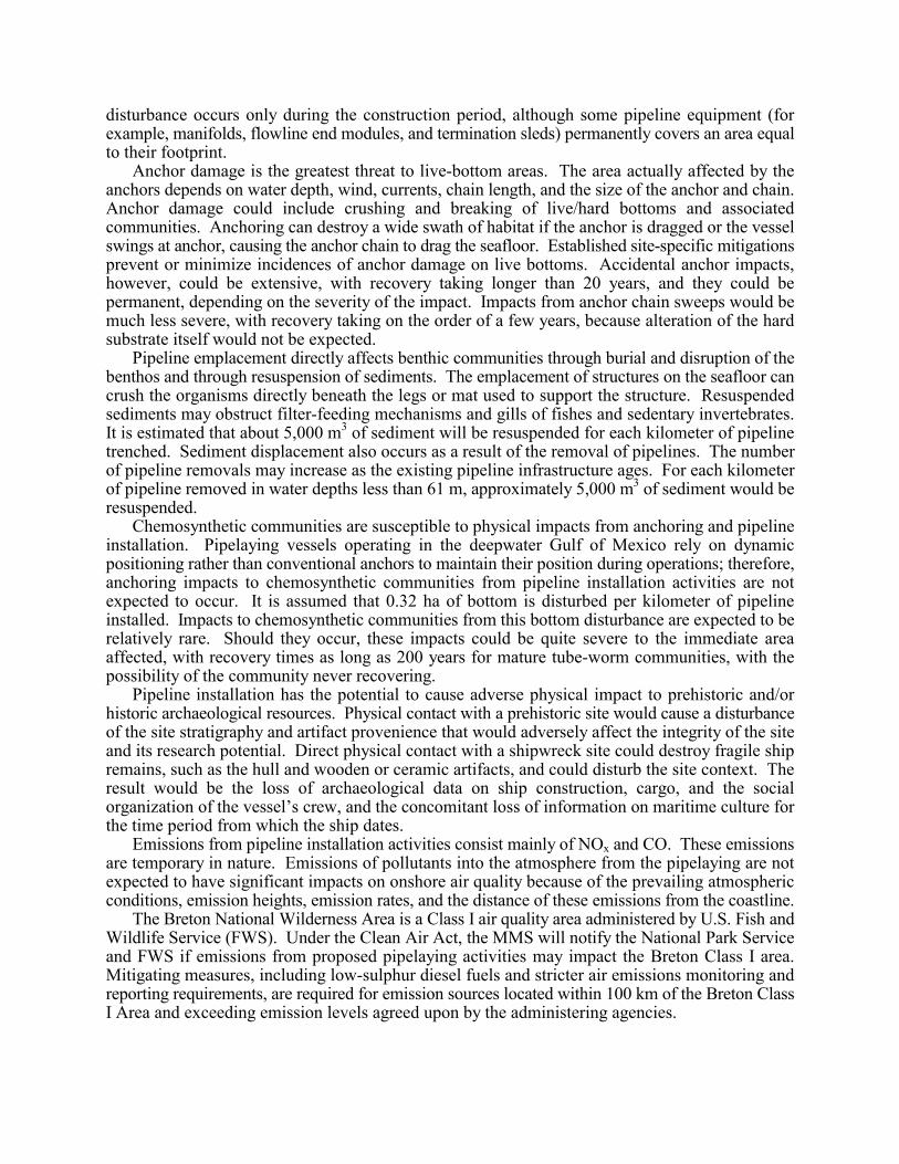
disturbance occurs only during the construction period, although some pipeline equipment (forexample, manifolds, flowline end modules, and termination sleds) permanently covers an area equalto their footprint.
Anchor damage is the greatest threat to live-bottom areas. The area actually affected by theanchors depends on water depth, wind, currents, chain length, and the size of the anchor and chain.Anchor damage could include crushing and breaking of live/hard bottoms and associatedcommunities. Anchoring can destroy a wide swath of habitat if the anchor is dragged or the vesselswings at anchor, causing the anchor chain to drag the seafloor. Established site-specific mitigationsprevent or minimize incidences of anchor damage on live bottoms. Accidental anchor impacts,however, could be extensive, with recovery taking longer than 20 years, and they could bepermanent, depending on the severity of the impact. Impacts from anchor chain sweeps would bemuch less severe, with recovery taking on the order of a few years, because alteration of the hardsubstrate itself would not be expected.
Pipeline emplacement directly affects benthic communities through burial and disruption of thebenthos and through resuspension of sediments. The emplacement of structures on the seafloor cancrush the organisms directly beneath the legs or mat used to support the structure. Resuspendedsediments may obstruct filter-feeding mechanisms and gills of fishes and sedentary invertebrates.It is estimated that about 5,000 m3 of sediment will be resuspended for each kilometer of pipelinetrenched. Sediment displacement also occurs as a result of the removal of pipelines. The numberof pipeline removals may increase as the existing pipeline infrastructure ages. For each kilometerof pipeline removed in water depths less than 61 m, approximately 5,000 m3 of sediment would beresuspended.
Chemosynthetic communities are susceptible to physical impacts from anchoring and pipelineinstallation. Pipelaying vessels operating in the deepwater Gulf of Mexico rely on dynamicpositioning rather than conventional anchors to maintain their position during operations; therefore,anchoring impacts to chemosynthetic communities from pipeline installation activities are notexpected to occur. It is assumed that 0.32 ha of bottom is disturbed per kilometer of pipelineinstalled. Impacts to chemosynthetic communities from this bottom disturbance are expected to berelatively rare. Should they occur, these impacts could be quite severe to the immediate areaaffected, with recovery times as long as 200 years for mature tube-worm communities, with thepossibility of the community never recovering.
Pipeline installation has the potential to cause adverse physical impact to prehistoric and/orhistoric archaeological resources. Physical contact with a prehistoric site would cause a disturbanceof the site stratigraphy and artifact provenience that would adversely affect the integrity of the siteand its research potential. Direct physical contact with a shipwreck site could destroy fragile shipremains, such as the hull and wooden or ceramic artifacts, and could disturb the site context. Theresult would be the loss of archaeological data on ship construction, cargo, and the socialorganization of the vessel’s crew, and the concomitant loss of information on maritime culture forthe time period from which the ship dates.
Emissions from pipeline installation activities consist mainly of NOx and CO. These emissionsare temporary in nature. Emissions of pollutants into the atmosphere from the pipelaying are notexpected to have significant impacts on onshore air quality because of the prevailing atmosphericconditions, emission heights, emission rates, and the distance of these emissions from the coastline.
The Breton National Wilderness Area is a Class I air quality area administered by U.S. Fish andWildlife Service (FWS). Under the Clean Air Act, the MMS will notify the National Park Serviceand FWS if emissions from proposed pipelaying activities may impact the Breton Class I area.Mitigating measures, including low-sulphur diesel fuels and stricter air emissions monitoring andreporting requirements, are required for emission sources located within 100 km of the Breton ClassI Area and exceeding emission levels agreed upon by the administering agencies.
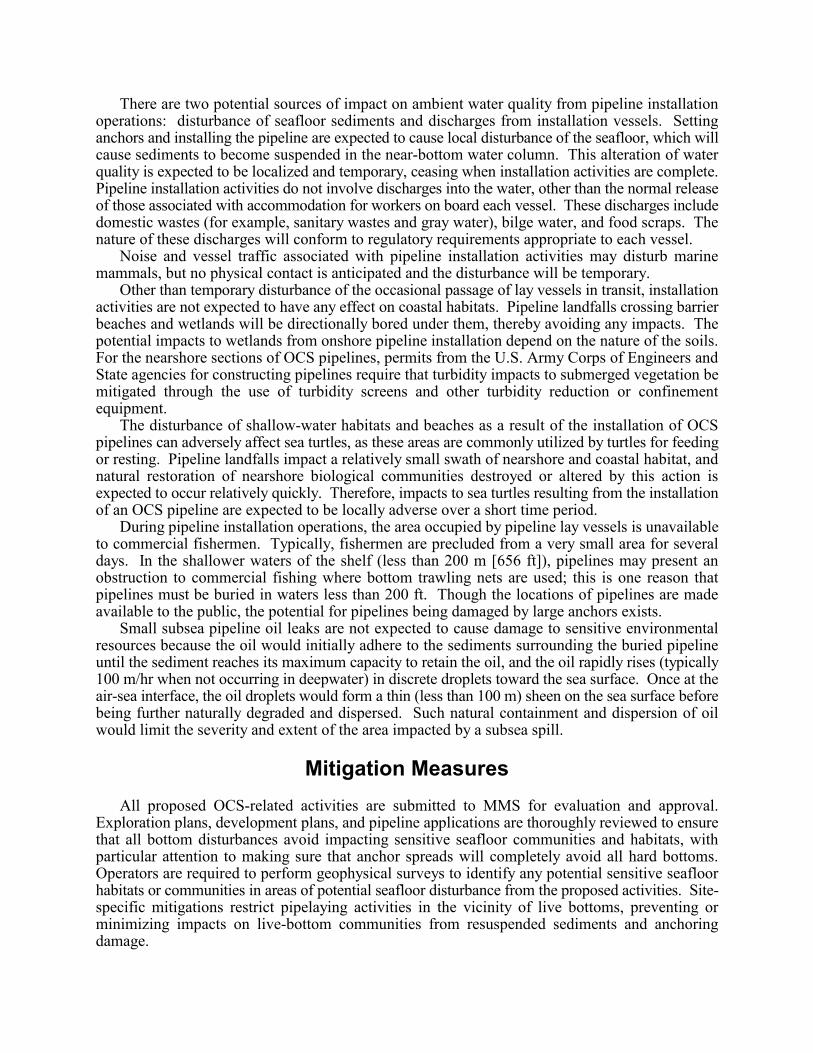
There are two potential sources of impact on ambient water quality from pipeline installationoperations: disturbance of seafloor sediments and discharges from installation vessels. Settinganchors and installing the pipeline are expected to cause local disturbance of the seafloor, which willcause sediments to become suspended in the near-bottom water column. This alteration of waterquality is expected to be localized and temporary, ceasing when installation activities are complete.Pipeline installation activities do not involve discharges into the water, other than the normal releaseof those associated with accommodation for workers on board each vessel. These discharges includedomestic wastes (for example, sanitary wastes and gray water), bilge water, and food scraps. Thenature of these discharges will conform to regulatory requirements appropriate to each vessel.
Noise and vessel traffic associated with pipeline installation activities may disturb marinemammals, but no physical contact is anticipated and the disturbance will be temporary.
Other than temporary disturbance of the occasional passage of lay vessels in transit, installationactivities are not expected to have any effect on coastal habitats. Pipeline landfalls crossing barrierbeaches and wetlands will be directionally bored under them, thereby avoiding any impacts. Thepotential impacts to wetlands from onshore pipeline installation depend on the nature of the soils.For the nearshore sections of OCS pipelines, permits from the U.S. Army Corps of Engineers andState agencies for constructing pipelines require that turbidity impacts to submerged vegetation bemitigated through the use of turbidity screens and other turbidity reduction or confinementequipment.
The disturbance of shallow-water habitats and beaches as a result of the installation of OCSpipelines can adversely affect sea turtles, as these areas are commonly utilized by turtles for feedingor resting. Pipeline landfalls impact a relatively small swath of nearshore and coastal habitat, andnatural restoration of nearshore biological communities destroyed or altered by this action isexpected to occur relatively quickly. Therefore, impacts to sea turtles resulting from the installationof an OCS pipeline are expected to be locally adverse over a short time period.
During pipeline installation operations, the area occupied by pipeline lay vessels is unavailableto commercial fishermen. Typically, fishermen are precluded from a very small area for severaldays. In the shallower waters of the shelf (less than 200 m [656 ft]), pipelines may present anobstruction to commercial fishing where bottom trawling nets are used; this is one reason thatpipelines must be buried in waters less than 200 ft. Though the locations of pipelines are madeavailable to the public, the potential for pipelines being damaged by large anchors exists.
Small subsea pipeline oil leaks are not expected to cause damage to sensitive environmentalresources because the oil would initially adhere to the sediments surrounding the buried pipelineuntil the sediment reaches its maximum capacity to retain the oil, and the oil rapidly rises (typically100 m/hr when not occurring in deepwater) in discrete droplets toward the sea surface. Once at theair-sea interface, the oil droplets would form a thin (less than 100 m) sheen on the sea surface beforebeing further naturally degraded and dispersed. Such natural containment and dispersion of oilwould limit the severity and extent of the area impacted by a subsea spill.
Mitigation Measures
All proposed OCS-related activities are submitted to MMS for evaluation and approval.Exploration plans, development plans, and pipeline applications are thoroughly reviewed to ensurethat all bottom disturbances avoid impacting sensitive seafloor communities and habitats, withparticular attention to making sure that anchor spreads will completely avoid all hard bottoms.Operators are required to perform geophysical surveys to identify any potential sensitive seafloorhabitats or communities in areas of potential seafloor disturbance from the proposed activities. Site-specific mitigations restrict pipelaying activities in the vicinity of live bottoms, preventing orminimizing impacts on live-bottom communities from resuspended sediments and anchoringdamage.
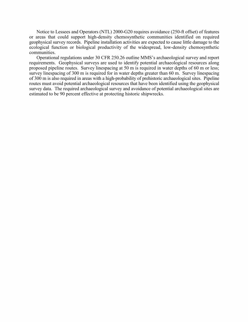
Notice to Lessees and Operators (NTL) 2000-G20 requires avoidance (250-ft offset) of featuresor areas that could support high-density chemosynthetic communities identified on requiredgeophysical survey records. Pipeline installation activities are expected to cause little damage to theecological function or biological productivity of the widespread, low-density chemosyntheticcommunities.
Operational regulations under 30 CFR 250.26 outline MMS’s archaeological survey and reportrequirements. Geophysical surveys are used to identify potential archaeological resources alongproposed pipeline routes. Survey linespacing at 50 m is required in water depths of 60 m or less;survey linespacing of 300 m is required for in water depths greater than 60 m. Survey linespacingof 300 m is also required in areas with a high-probability of prehistoric archaeological sites. Pipelineroutes must avoid potential archaeological resources that have been identified using the geophysicalsurvey data. The required archaeological survey and avoidance of potential archaeological sites areestimated to be 90 percent effective at protecting historic shipwrecks.
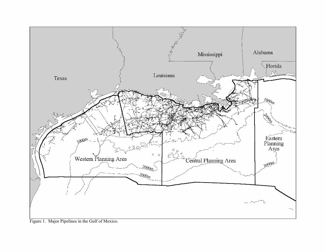
Figure 1. Major Pipelines in the Gulf of Mexico.