Embed Size (px)
Citation preview

A Brief Introduction to
Ranplan’s Radiowave
Propagation Simulator- RRPSPropagation Simulator- RRPS
Dr Zhihua Lai

Outline
� Importance of Radiowave Propagation Modelling� What are they and what they do
� Existing propagation models
� Ranplan Radiowave Propagation Simulator

Radiowave Propagation
Modelling: Basics� Radiowave attenuates when they propagate
� Four main mechanism: reflection, diffraction,
transmission and scattering
� Long term fading, shadowing.. Path loss computation

Radiowave Multipath Reception
� Reception due to multipath propagation

Why propagation modelling
� Path Loss Computation
� Link Budget , Best Server etc..
� Compute the received signal power, Obtain a coverage
prediction
� Study the statistics of the channel� Study the statistics of the channel
� -> depending on
� The emitters (radiated power, antenna pattern…)
� The environment (buildings, materials…)
� -> necessary for:
� Wireless Network Planning (find the best parameters for the network)
� Performances analysis (system level simulations)
� Test different technologies
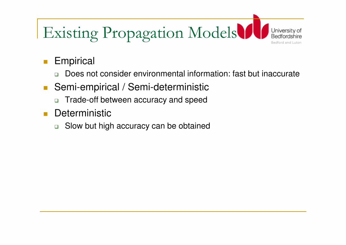
Existing Propagation Models
� Empirical
� Does not consider environmental information: fast but inaccurate
� Semi-empirical / Semi-deterministic
� Trade-off between accuracy and speed
� Deterministic
Slow but high accuracy can be obtained� Slow but high accuracy can be obtained

Categories of Propagation
ModelsDeterministic
Multi WallRay tracing/launching FDTD
Diffraction
Multi Wall
Dominant Path
Ray tracing/launching
Beam tracing
Ray SplittingMotif model
Statistical GTD/UTD
FDTD
TLM/ParFlow
Precision / Complexity

One Example of Empirical Model
� One Slopeconsiders distance and path loss exponent
fast but inaccurate
From AWE communication

One example of Semi-
empirical/deterministic Model� COST 231 Multi-Wall
� often pessimistic
� considers the number of walls and floors between emitter and receiver
� considers material
From AWE communication

Deterministic Models
� Ray-based
� Ray Launching, Ray Tracing, Dominant Ray
� Need to include the use of GTD / UTD (Geometry Theory of Diffraction) / (Uniformed Theory of Diffraction)
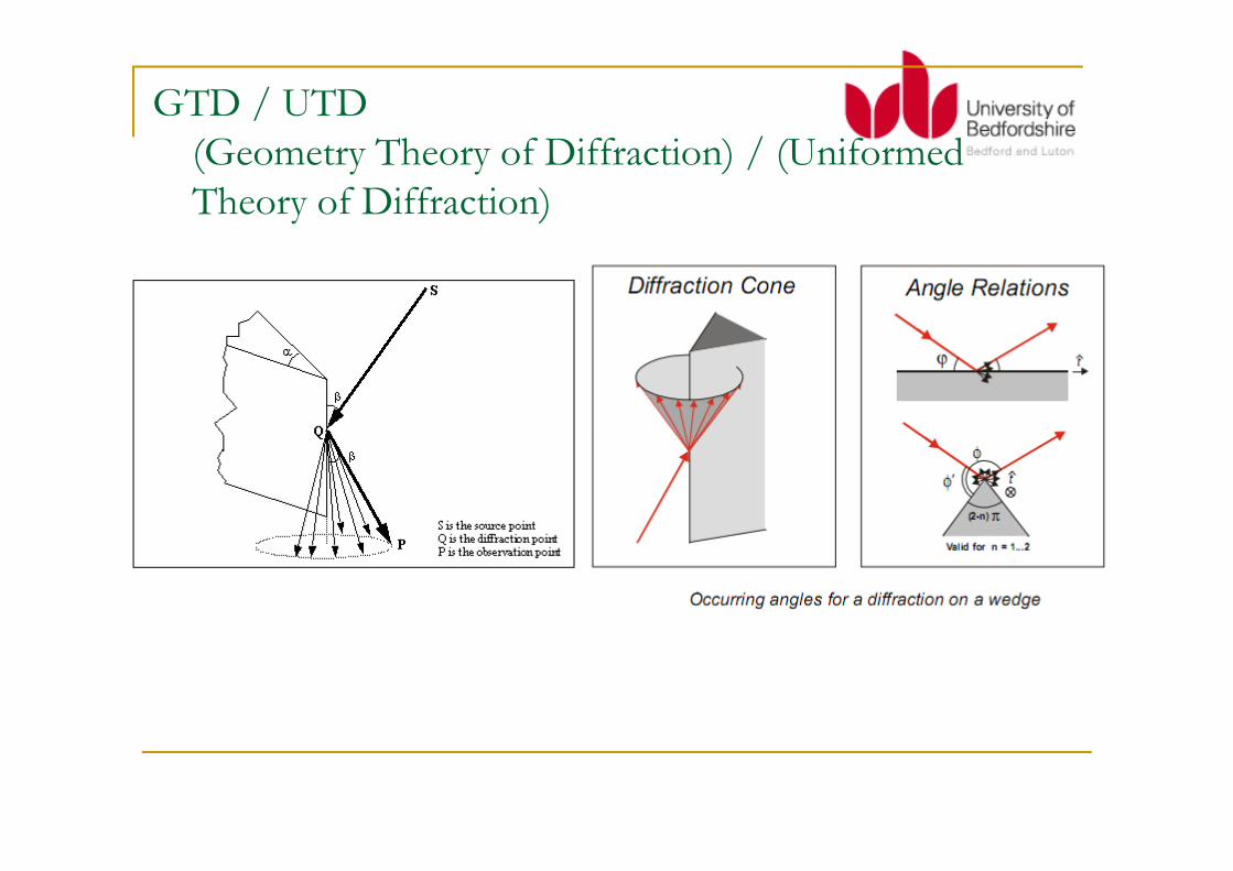
GTD / UTD
(Geometry Theory of Diffraction) / (Uniformed
Theory of Diffraction)

Ray-based Models
� Ray Tracing & Ray Launching� Difficult to program (ray-object intersection test)� Time-consuming (expensive ray-object intersection test)� Need GTD/UTD� The problem can be split into parts� Frequency domain� Narrowband� Database pre-processed
Ray Launching� Ray Launching� Consider rays from emitter� Suitable for large area coverage� Rays may be missed due to angle separation� Complexity linear with ray iterations� Limited iterations considered
� Ray Tracing� Image based (consider rays backwards)� Suitable for few locations prediction� Precisely calculate dominant rays� Complexity exponentially increases with ray iterations� Limited iterations considered

Computation of reflection and
diffraction� Empirical Interaction Model
� reflection loss (in dB)
� penetration loss (in dB)
� min. diffraction loss (in dB)
� max. diffraction loss (in dB)
� diffraction loss of diffracted ray (in dB)
� Deterministic Interaction Model� Deterministic Interaction Model� Fresnel Equations for the determination of the reflection and
transmission loss
� GTD/UTD for the determination of the diffraction loss.
� (relative) permittivity
� (relative) permeability
� Conductivity
� Thickness of walls (roofs etc)

FDTD
� Finite Difference Time Domain (FDTD)� Solves Maxwell Equations
� Time domain
� Broadband
� Close to physics (inherently includes diffractions etc)
No special need to take care of Fresnel Zones� No special need to take care of Fresnel Zones
� Simple programming (recursive)
� Simple database structures with volume elements
� Tremendous running time and memory requirement
� Often 2D, usually 3D is not feasible (time and memory)
� Frequency -> wavelength -> spatial step (grid size)
� Fake frequency and calibration

Ranplan Radiowave
Propagation Simulator (RRPS)� Ray-based: Ray Launching + Ray Tracing
� Accurate � 6-8 dB RMSE
� Fast (Millions of receiver locations within few minutes (on standard PCs)� Distributed/Parallel implementation
� Multithreading� Multithreading
� Designed for outdoor, indoor, indoor-to-outdoor and outdoor-to-indoor
scenarios
� Field Strength (Path Loss), Multipath (Delay Spread …)
� Full 3D
� No need to pre-process visibility tree
� Propagation library
� A full range of API supported (e.g. invoking RRPS)
RRPS - Overview
� Input from Building Data (Vector), Antenna,
and Network Configuration
� Preprocess into a discrete data set
� Computation via Vertical Diffraction (VD), � Computation via Vertical Diffraction (VD),
Horizontal Reflection and Diffraction (HRD),
Line-Of-Sight (LOS).
� Post-processing
� Output to 3D path loss matrix and multipath
components

RRPS – Overview contd.

RRPS – Acceleration Overview
1. Intelligent Algorithms (ref [2][5])
2. Avoid Angular Dispersion / Double Counting of
rays (ref[3])
3. Parallelisation via Multithreading/POP-C++ [4]3. Parallelisation via Multithreading/POP-C++ [4]
4. The use of Ray Tracing and Ray Launching +
Vector and Raster
5. The use of Breadth-First and Deep-First
Search
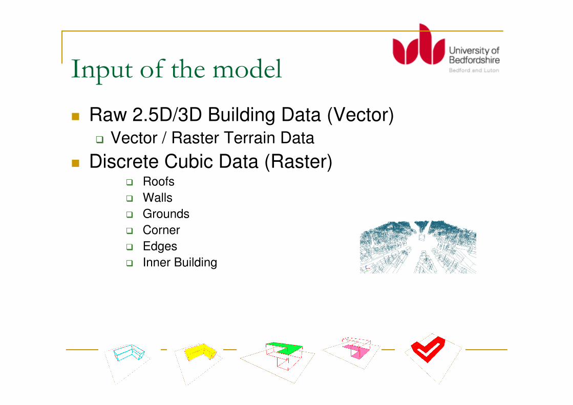
Input of the model
� Raw 2.5D/3D Building Data (Vector) � Vector / Raster Terrain Data
� Discrete Cubic Data (Raster) � Roofs
� Walls� Walls
� Grounds
� Corner
� Edges
� Inner Building

Output of the model
� 3D Path Loss Matrix
� Multi-Paths information
� Total length of a ray
� The number of diffractions� The number of diffractions
� The number of reflections
� The number of transmission
Outline of the model
� L-O-S computation
� Horizontal reflection and diffraction (Non-roof
top)
� Roof top diffraction� Roof top diffraction
� Post-processing

Collection L-O-S pixels
� Mark visible area of emitter
� Add LOS paths
� Collect first-filled pixels
� Building edges (corner) � Building edges (corner)
� Building walls
� Building roofs

None-roof top 3D ray launching
� Reflections and diffractions
� No transmission if no indoor prediction
� Roof-top diffractions excluded
� Disable ray loops� Disable ray loops
� Path loss threshold
� Law of diffractions
� (Keller Cone)

Propagation via HRD
� Observation of reflection & diffractions (without roof-top diffractions)
� Set a maximum path loss threshold
� R5D5, R8D8, R15D15

Running Time (seconds)
� A: 2 Cores, 2.5GHz,
4GB
� B: 2 Cores, 2.2GHz,
2GB
� C: 1 Core, 1.7GHz,
512MB
72.332.620.6R15D15
21.08.77.3R8D8
20.55.74.3R7D7
13.05.54.1R5D5
3.71.51.2R3D3
CBA

An extreme test
(for demonstration only)
� 300dB maximum
� Loss Refl = 3dB
� Loss Diff = 6dB� Loss Diff = 6dB
� Maximum 30 refl
� Maximum 30 diff
� In 5 minutes on
� 2.4GHz
� Dual Core, 4G RAM

Roof-top (vertical) diffractions
� A fast pixel-checking-based calculation
� Runtime complexity O(n3)
� Assume flat ground but support terrain and vegetation data
� Complexity does not grow by the number of buildings (objects)
� Machine A (4 seconds), B (7), C(13)

Roof-top (vertical) diffractions
� Preprocess the height of building pixels
� Group building pixels
� To obtain the number of minimal diffractions needed between A and B� Launch a ray to the farthest building it can see
� Move to the top of this building and iterate until it sees B
� Cache “visible” function (speed up 60%) � Cache “visible” function (speed up 60%)
� Speed up around 40% if you know� Building A and B are adjacent
� Highest Building C between A and B
� If C is higher than both A and B
� If C is lower than both A and B
� Add one more diffraction if a ray goes up and down (walk along building roofs)
� Stop until marked LOS pixels
Add indoor prediction
� Indoor prediction added from
� Path loss at building roofs + 1 transmission
� Path loss around building walls + 1 transmission

Pre & Post-processing
� Constructing cubic rasterized data
� Post-processing
� Antenna pattern adjustment
� Indoor prediction� Indoor prediction
� Global adjustment

Calibration
� Parameters
� Path Loss Coefficient
� Loss for Reflection
� Loss for Diffraction� Loss for Diffraction
� Loss for Roof-top Diffraction
� Loss for Transmission
� Global Adjustment
� Improve the accuracy
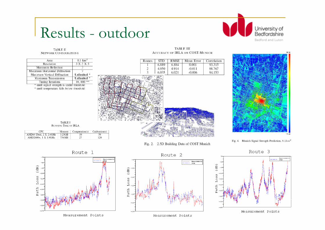
Results - outdoor

Results - Outdoor

Results – Indoor
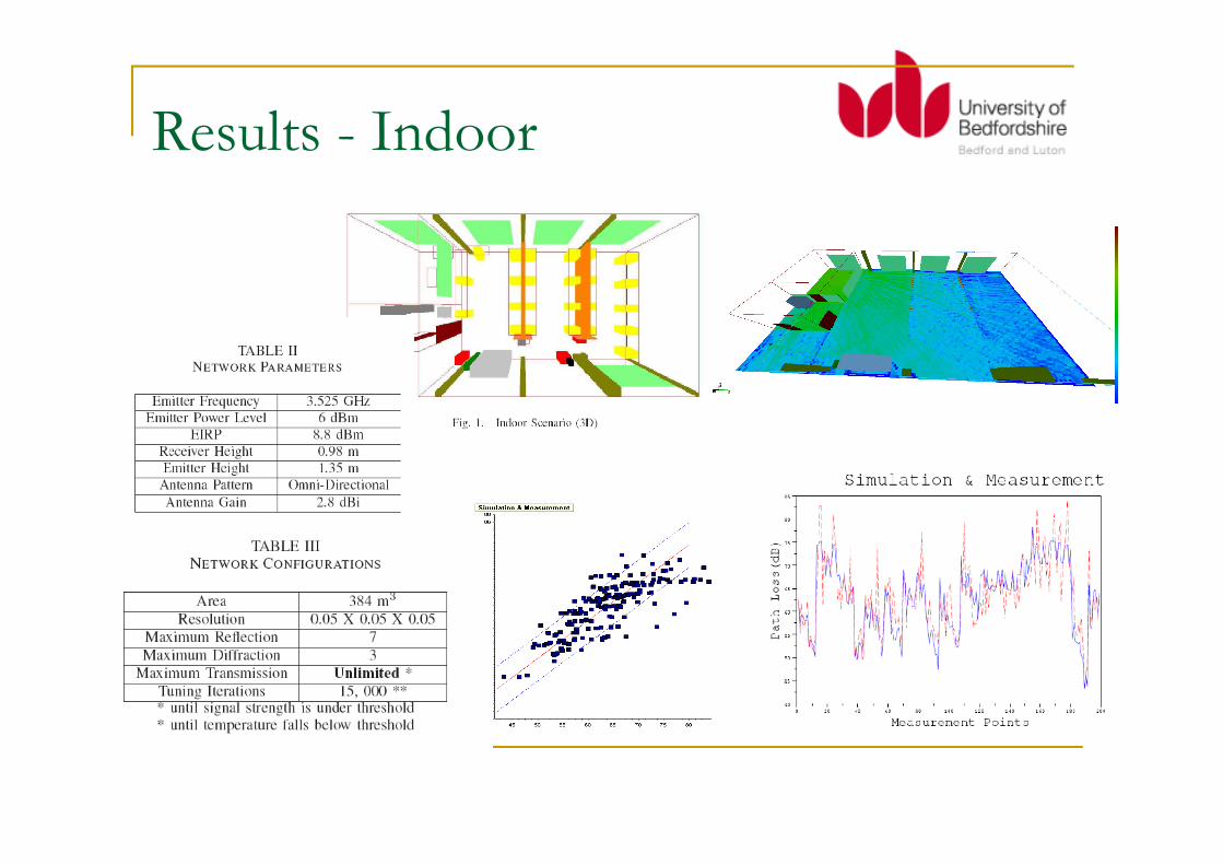
Results - Indoor

Results - Indoor
0 20 40 60 80 100 120 140 160 180 200−70
−60
−50
−40
−30
Index of Receiver Locations
Pow
er
(dB
m)
IRLA
Measurement
Index of Receiver Locations
0 20 40 60 80 100 120 140 160 180 200−70
−60
−50
−40
−30
Index of Receiver Locations
Pow
er
(dB
m)
MR−FDPF
Measurement
0 20 40 60 80 100 120 140 160 180 200−70
−60
−50
−40
−30
Index of Receiver Locations
Pow
er
(dB
m)
Multi−wall
Measurement

Results – Indoor to Outdoor
� Less than 1 minute.
� Millions of rays

Results – Outdoor to Indoor
� Ref: [5][7][8]

Results – Outdoor to Indoor
� Ref: [5][7][8]

Parallelisation
1. Why ?
1. To be faster (for Automated Cell Planning)
2. How ?
1. Static data distribution (distributed)1. Static data distribution (distributed)
1. Each processor has been assigned a fixed number of computation in advance
2. Dynamic data distribution (multithreading)
1. Threads are assigned a task whenever idle.
3. Every object has accessed same data (antenna,
building, network parameters …)
4. Collect results (multipath, path loss)

POP-C++ (Parallel Object-oriented
Programming in C++)1. Implementation of parallel object model as
an extension of C++
2. Implicit message-passing via object-
oriented designoriented design
3. Grid-enable (can be used together with
Globus Toolkit 4)
4. Various method invocation semantics
5. http://www.eif.ch/gridgroup/popc/

Parallelisation without Job Mgr

Parallelisation with Job Mgr
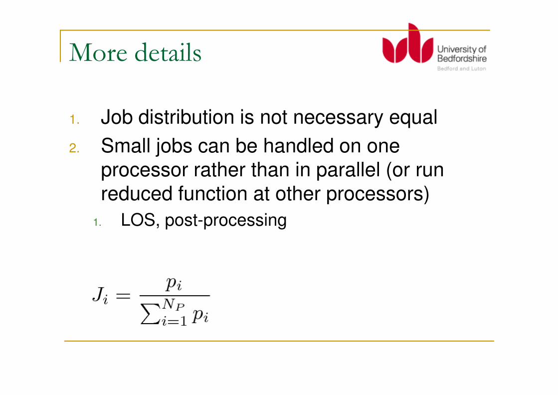
More details
1. Job distribution is not necessary equal
2. Small jobs can be handled on one
processor rather than in parallel (or run
reduced function at other processors)reduced function at other processors)
1. LOS, post-processing

Intermediate Results

Experiments - Parallelisation
Running time (s)
300
250
200
(B) 12G RAM, 3.0 GHz Quad
(A) Kerrighed
(C) 4G RAM, 2.5 GHz Dual
1210 14642 16 18
The number of parallel objects
208
Running time (s)
0
150
100
50

Experiments – Best Servers

[1] Zhihua Lai, Nik Bessis, Guillaume de la Roche, Pierre Kuonen, Jie Zhang and Gordon Clapworthy, The characterisation of human body influence on indoor 3.5 GHz path loss measurement, PlanNet, Second International Workshop on Planning and Optimisation of Wireless Communication Networks, IEEE WCNC Workshop, IEEE, Sydney, Australia, April 18-21, 2010.
[2] Zhihua Lai, Nik Bessis, Guillaume de la Roche, Pierre Kuonen, Jie Zhang and Gordon Clapworthy, On the use of an intelligent ray launching for indoor scenarios, EuCAP, The Fourth European Conference on Antennas and Propagation, IEEE, Barcelona, Spain, April 12-16, 2010.
[3] Zhihua Lai, Nik Bessis, Guillaume de la Roche, Pierre Kuonen, Jie Zhang, and Gordon Clapworthy, A new approach to solve angular dispersion of discrete ray launching for urban scenarios, LAPC, Loughborough Antennas & Propagation Conference, Burleigh Court Conference Centre, IEEE, Loughborough University, United Kingdom, November 16-17, 2009, ISBN: 978-1-4244-2721-5.
[4] Zhihua Lai, Nik Bessis, Pierre Kuonen, Guillaume de la Roche, Jie Zhang and Gordon Clapworthy, A performance evaluation of a grid-enabled object-oriented parallel outdoor ray launching for wireless network performance evaluation of a grid-enabled object-oriented parallel outdoor ray launching for wireless network coverage prediction, ICWMC, The Fifth International Conference on Wireless and Mobile Communications, IEEE & ACM, Cannes/La Bocca, French Riviera, France, August 23-29, 2009, ISBN: 978-0-7695-3750-4.
[5] Zhihua Lai, Nik Bessis, Guillaume de la Roche, Hui Song, Jie Zhang and Gordon Clapworthy, An intelligent ray launching for urban propagation prediction, EuCAP, The Third European Conference on Antennas and Propagation, IEEE & VDE, Berlin, Germany, March 23-27, 2009, ISBN: 978-3-8007-3152-7.
[6] Zhihua Lai, Nik Bessis, Jie Zhang and Gordon Clapworthy, Some thoughts on adaptive grid-enabled optimisation algorithms for wireless network simulation and planning, AHM, All Hands Meeting, UK e-Science, NeSc, Nottingham, United Kingdom, September 10-13, 2007, ISBN: 978-0-9553988-3-4.
[7] Guillaume de la Roche, Paul Flipo, Zhihua Lai, Guillaume Villemaud, Jie Zhang and Jean-Marie Gorce, Combined Model for Outdoor to Indoor Radio Propagation, In 10th COST2100 Management Meeting, TD(10)10045, Athens, Greece, February 3-5, 2010.
[8] Guillaume de la Roche, Paul Flipo, Zhihua Lai, Guillaume Villemaud, Jie Zhang and Jean-Marie Gorce, Combination of geometric and finite difference models for radio wave propagation in outdoor to indoor scenarios, EuCAP, The Fourth European Conference on Antennas and Propagation, IEEE, Barcelona, Spain, April 12-16, 2010.
![Agile V Model.ppt - RBCS, Inc · I’ll show you… The Agile V Model ... agile The Agile V Model ... Agile V Model.ppt [Compatibility Mode]](https://img.pdfslide.us/doc/110x75/5acdaca47f8b9a6a678dca0e/agile-v-modelppt-rbcs-inc-ll-show-you-the-agile-v-model-agile-the-agile.jpg)


![[GUNSMITHING] The 12g Pistol](https://img.pdfslide.us/doc/110x75/5529676f550346b52e8b474c/gunsmithing-the-12g-pistol.jpg)