Embed Size (px)
Citation preview
B
jedlccg
dfpcbtbttwp
Leic1i
iNL
J
Downlo
James D. Van de Vene-mail: [email protected]
Arthur G. Erdmane-mail: [email protected]
Mechanical Engineering Department,University of Minnesota,
111 Church Street Southeast,Minneapolis, MN 55455
Bridging Gaps in LaserTransmission Welding ofThermoplasticsGaps at part interfaces pose a major challenge for laser transmission welding (LTW) ofthermoplastics due to the reliance on contact conduction between the absorptive andtransmissive parts. In industrial applications, gaps between parts can occur for a varietyof tolerance and process control reasons. Previous experimental and modeling work inLTW has focused on gap-free joints, with little attention to bridging a gap with thermalexpansion of the absorbing material. A two-dimensional comprehensive numerical modelsimulated bridging gaps in LTW. Using the model, operating parameters were selectedfor welding across a 12.7 �m gap and a 25.4 �m gap by creating sufficient thermalstrain to bridge the gap and form a weld. Using these operating parameters, PVCsamples were welded in a T-joint geometry with a designed gap. The quality of the weldswas assessed visually, by destructive force testing and by measuring the weld size toquantify the weld strength. All the experimental samples, for the two gap sizes, bridgedthe gap and formed welds. The average weld strength of the 12.7 �m gap samples was16.1 MPa, while the 25.4 �m gap samples had an average strength of 10.0 MPa. Gapswere successfully bridged with LTW by using a two-dimensional model to design theoperating parameters. To achieve higher modeling accuracy, a three-dimensional modelmight better simulate the thermal diffusion in the direction of laser travel.�DOI: 10.1115/1.2769731�
Keywords: laser welding, gap bridging, modeling, PVC
ackground
Laser transmission welding �LTW� is a popular thermoplasticoining option because it is a contact-free operation that createsxcellent quality welds. Due to a relatively large operating win-ow for variation in process parameters, including weld velocity,aser power, and clamping pressure, LTW is a robust joining pro-ess from a manufacturing viewpoint �1–3�. One important pro-ess variable not previously explored in LTW is the presence ofaps in the joint.
Gaps occur in a joint for a variety of reasons including poorimensional control of mating part features, inadequate clampingorce, poor clamping location, warping, and poor joint design. Theresence of gaps in LTW using the contour method is a majoroncern because the process relies on thermal contact conductionetween the absorptive part and the transmissive part �2�. Whenhese two parts are not in contact, conduction of the heat createdy laser radiation will not occur across the part interface, causinghe temperature of the absorptive part to rapidly increase. If thehermal expansion of the absorptive part does not create contactith the transmissive part and “bridge” the gap, thermal decom-osition of the absorptive part will likely occur.
Very little previous work has investigated bridging gaps inTW from either an experimental or a modeling approach. Russekt al. �4� briefly reports that bridging gaps is possible by increas-ng the optical penetration depth through changing the absorptionoefficient of absorbing material. This work states that gaps up to50 �m are bridgeable using a circular laser spot in contour weld-ng �4�. It should be noted that simultaneous and quasisimulta-
Contributed by the Manufacturing Engineering Division of ASME for publicationn the JOURNAL OF MANUFACTURING SCIENCE AND ENGINEERING. Manuscript receivedovember 3, 2006; final manuscript received July 6, 2007. Review conducted by Y.
awrence Yao.ournal of Manufacturing Science and EngineeringCopyright © 20
aded 28 Nov 2007 to 130.215.49.80. Redistribution subject to ASME
neous variants of LTW create meltdown at the joint. Bridginggaps is not as significant of a challenge with these two variants ofLTW as it is for the contour method.
Designing a laser transmission weld to bridge a gap requirescareful consideration of the heating distribution. The absorbingpart must be heated slowly to allow conduction into the bulk ofthe material, which will increase the thermal strain and allow thetwo parts to meet. Achieving the necessary thermal strain is nottrivial because the thermal conductivity of polymers is relativelylow and during a longer weld time, the possibility of thermaldecomposition becomes greater.
This paper presents an investigation of bridging gaps in LTW ofPVC using the contour method. Two different gap sizes will bediscussed, 12.7 �m and 25.4 �m. Using a numerical model pre-viously developed �2�, simulations were run that design operatingparameters for both gap sizes. Using the designed operating pa-rameters, samples were welded and assessed for aesthetics, weldstrength, and weld width.
Laser Transmission Welding Model DescriptionA comprehensive numerical model was developed from first
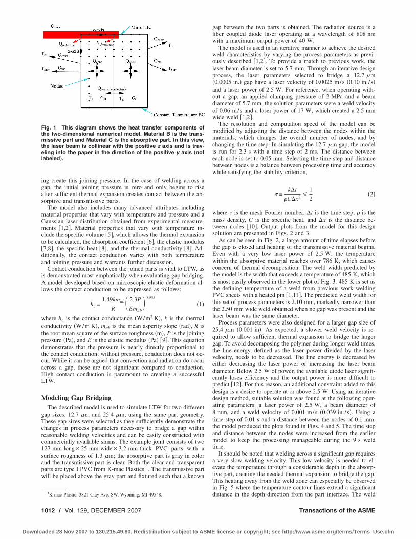
principles of heat transfer and present in previous works �1–3�.This model uses the energy balance method to calculate the tem-perature at nodes in two dimensions: into the material �z direction�and perpendicular to the direction of laser travel �x direction�. Themodel includes radiation from the material surfaces to the sur-roundings, convection from the external surfaces to the surround-ing air, laser reflection from both surfaces, heat generation withineach material from laser absorption, conduction within each ma-terial, and contact conduction between the two parts. A diagramexplaining the heat transfer aspects of the model can be seen inFig. 1.
In addition to calculating the temperature of each node, themodel also calculates the joining pressure at the interface between
the two parts. Initial clamping and thermal expansion during heat-DECEMBER 2007, Vol. 129 / 101107 by ASME
license or copyright; see http://www.asme.org/terms/Terms_Use.cfm
igas
mGmct�da
iAl
wctpdtcaHL
M
gTcrc1sapw
Ftmtel
1
Downlo
ng create this joining pressure. In the case of welding across aap, the initial joining pressure is zero and only begins to risefter sufficient thermal expansion creates contact between the ab-orptive and transmissive parts.
The model also includes many advanced attributes includingaterial properties that vary with temperature and pressure and aaussian laser distribution obtained from experimental measure-ents �1,2�. Material properties that vary with temperature in-
lude the specific volume �5�, which allows the thermal expansiono be calculated, the absorption coefficient �6�, the elastic modulus7,8�, the specific heat �8�, and the thermal conductivity �8�. Ad-itionally, the contact conduction varies with both temperaturend joining pressure and warrants further discussion.
Contact conduction between the joined parts is vital to LTW, ass demonstrated most emphatically when evaluating gap bridging.
model developed based on microscopic elastic deformation al-ows the contact conduction to be expressed as follows:
hc =1.49kmab
R� 2.3P
Emab�0.935
�1�
here hc is the contact conductance �W/m2 K�, k is the thermalonductivity �W/m K�, mab is the mean asperity slope �rad�, R ishe root mean square of the surface roughness �m�, P is the joiningressure �Pa�, and E is the elastic modulus �Pa� �9�. This equationemonstrates that the pressure is nearly directly proportional tohe contact conduction; without pressure, conduction does not oc-ur. While it can be argued that convection and radiation do occurcross a gap, these are not significant compared to conduction.igh contact conduction is paramount to creating a successfulTW.
odeling Gap BridgingThe described model is used to simulate LTW for two different
ap sizes, 12.7 �m and 25.4 �m, using the same part geometry.hese gap sizes were selected as they sufficiently demonstrate thehanges in process parameters necessary to bridge a gap withineasonable welding velocities and can be easily constructed withommercially available shims. The example joint consists of two27 mm long�25 mm wide�3.2 mm thick PVC parts with aurface roughness of 1.3 �m; the absorptive part is gray in colornd the transmissive part is clear. Both the clear and transparentarts are type I PVC from K-mac Plastics 1. The transmissive partill be placed above the gray part and fixtured such that a known
1
ig. 1 This diagram shows the heat transfer components ofhe two-dimensional numerical model. Material B is the trans-
issive part and Material C is the absorptive part. In this view,he laser beam is collinear with the positive z axis and is trav-ling into the paper in the direction of the positive y axis „notabeled….
K-mac Plastic, 3821 Clay Ave. SW, Wyoming, MI 49548.
012 / Vol. 129, DECEMBER 2007
aded 28 Nov 2007 to 130.215.49.80. Redistribution subject to ASME
gap between the two parts is obtained. The radiation source is afiber coupled diode laser operating at a wavelength of 808 nmwith a maximum output power of 40 W.
The model is used in an iterative manner to achieve the desiredweld characteristics by varying the process parameters as previ-ously described �1,2�. To provide a match to previous work, thelaser beam diameter is set to 5.7 mm. Through an iterative designprocess, the laser parameters selected to bridge a 12.7 �m�0.0005 in.� gap have a laser velocity of 0.0025 m/s �0.10 in./ s�and a laser power of 2.5 W. For reference, when operating with-out a gap, an applied clamping pressure of 2 MPa and a beamdiameter of 5.7 mm, the solution parameters were a weld velocityof 0.06 m/s and a laser power of 17 W, which created a 2.5 mmwide weld �1,2�.
The resolution and computation speed of the model can bemodified by adjusting the distance between the nodes within thematerials, which changes the overall number of nodes, and bychanging the time step. In simulating the 12.7 �m gap, the modelis run for 2.3 s with a time step of 2 ms. The distance betweeneach node is set to 0.05 mm. Selecting the time step and distancebetween nodes is a balance between processing time and accuracywhile satisfying the stability criterion,
� =k�t
�C�x2 �1
2�2�
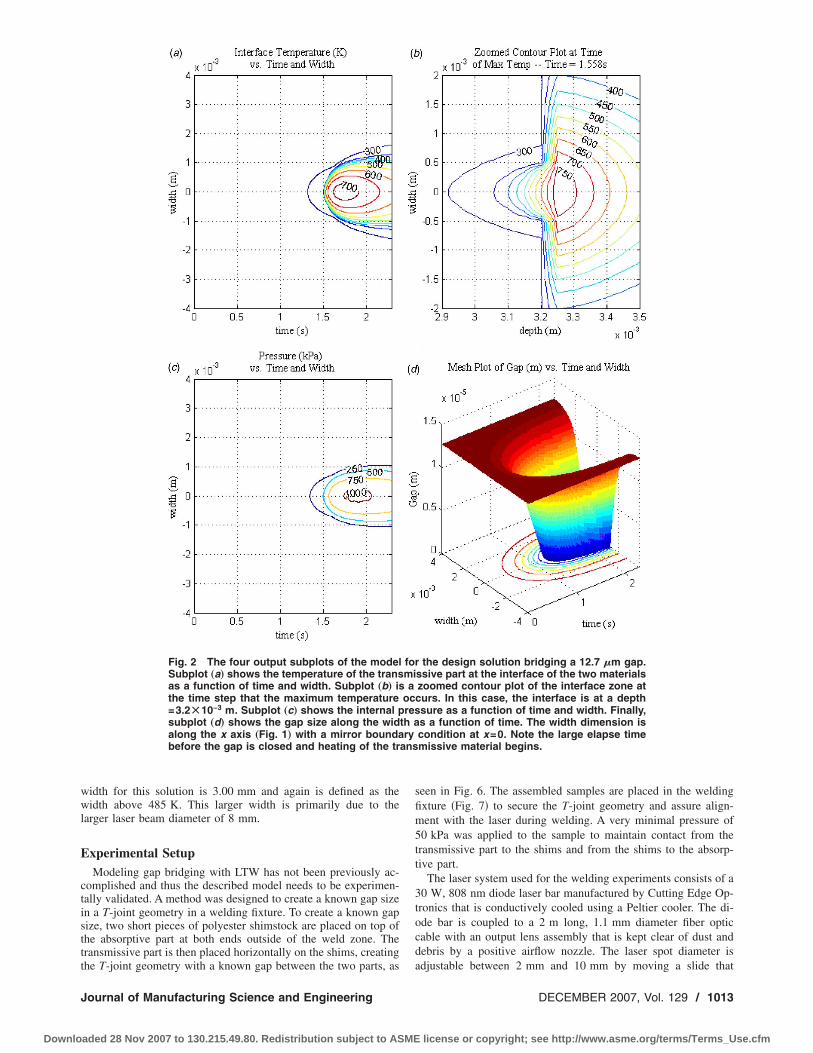
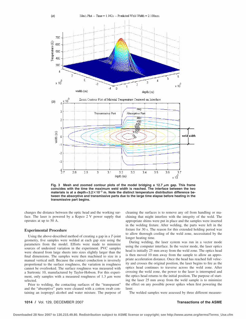
where � is the mesh Fourier number, �t is the time step, � is themass density, C is the specific heat, and �x is the distance be-tween nodes �10�. Output plots from the model for this designsolution are presented in Figs. 2 and 3.
As can be seen in Fig. 2, a large amount of time elapses beforethe gap is closed and heating of the transmissive material begins.Even with a very low laser power of 2.5 W, the temperaturewithin the absorptive material reaches over 786 K, which causesconcern of thermal decomposition. The weld width predicted bythe model is the width that exceeds a temperature of 485 K, whichis most easily observed in the lower plot of Fig. 3. 485 K is set asthe defining temperature of a weld from previous work weldingPVC sheets with a heated pin �1,11�. The predicted weld width forthis set of process parameters is 2.10 mm, markedly narrower thanthe 2.50 mm wide weld obtained when no gap was present and thelaser beam was the same diameter.
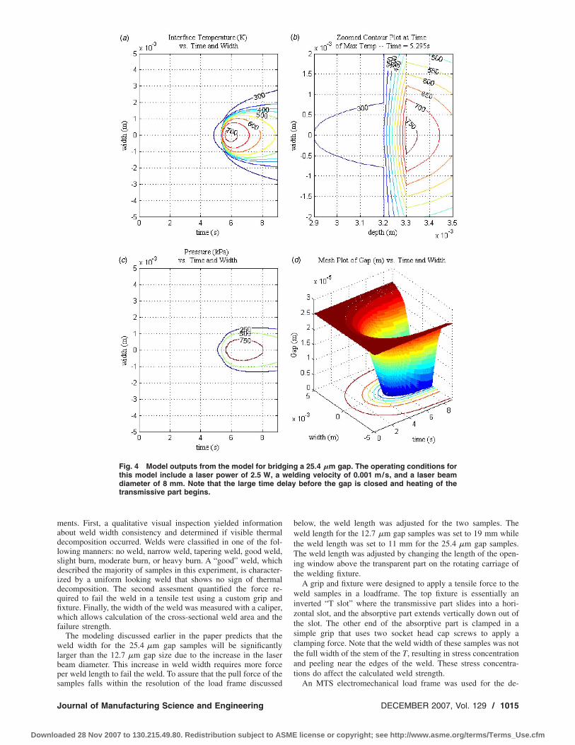
Process parameters were also designed for a larger gap size of25.4 �m �0.001 in�. As expected, a slower weld velocity is re-quired to allow sufficient thermal expansion to bridge the largergap. To avoid decomposing the polymer during longer weld times,the line energy, defined as the laser power divided by the laservelocity, needs to be decreased. The line energy is decreased byeither decreasing the laser power or increasing the laser beamdiameter. Below 2.5 W of power, the available diode laser signifi-cantly loses efficiency and the output power is more difficult topredict �12�. For this reason, an additional constraint added to thisdesign is a desire to operate at or above 2.5 W. Using an iterativedesign method, suitable solution was found at the following oper-ating parameters: a laser power of 2.5 W, a beam diameter of8 mm, and a weld velocity of 0.001 m/s �0.039 in./ s�. Using atime step of 0.01 s and a distance between the nodes of 0.1 mm,the model produced the plots found in Figs. 4 and 5. The time stepand distance between the nodes were increased from the earliermodel to keep the processing manageable during the 9 s weldtime.
It should be noted that welding across a significant gap requiresa very slow welding velocity. This low velocity is needed to el-evate the temperature through a considerable depth in the absorp-tive part, creating the needed thermal expansion to bridge the gap.This heating away from the weld zone can especially be observedin Fig. 5 where the temperature contour lines extend a significant
distance in the depth direction from the part interface. The weldTransactions of the ASME
license or copyright; see http://www.asme.org/terms/Terms_Use.cfm
wwl
E
ctisttt
ans
J
Downlo
idth for this solution is 3.00 mm and again is defined as theidth above 485 K. This larger width is primarily due to the
arger laser beam diameter of 8 mm.
xperimental SetupModeling gap bridging with LTW has not been previously ac-
omplished and thus the described model needs to be experimen-ally validated. A method was designed to create a known gap sizen a T-joint geometry in a welding fixture. To create a known gapize, two short pieces of polyester shimstock are placed on top ofhe absorptive part at both ends outside of the weld zone. Theransmissive part is then placed horizontally on the shims, creating
Fig. 2 The four output subplots of the modelSubplot „a… shows the temperature of the transas a function of time and width. Subplot „b… isthe time step that the maximum temperature=3.2Ã10−3 m. Subplot „c… shows the internal psubplot „d… shows the gap size along the widalong the x axis „Fig. 1… with a mirror boundabefore the gap is closed and heating of the tr
he T-joint geometry with a known gap between the two parts, as
ournal of Manufacturing Science and Engineering
aded 28 Nov 2007 to 130.215.49.80. Redistribution subject to ASME
seen in Fig. 6. The assembled samples are placed in the weldingfixture �Fig. 7� to secure the T-joint geometry and assure align-ment with the laser during welding. A very minimal pressure of50 kPa was applied to the sample to maintain contact from thetransmissive part to the shims and from the shims to the absorp-tive part.
The laser system used for the welding experiments consists of a30 W, 808 nm diode laser bar manufactured by Cutting Edge Op-tronics that is conductively cooled using a Peltier cooler. The di-ode bar is coupled to a 2 m long, 1.1 mm diameter fiber opticcable with an output lens assembly that is kept clear of dust anddebris by a positive airflow nozzle. The laser spot diameter is
the design solution bridging a 12.7 �m gap.ssive part at the interface of the two materialszoomed contour plot of the interface zone atcurs. In this case, the interface is at a depthsure as a function of time and width. Finally,s a function of time. The width dimension iscondition at x=0. Note the large elapse timemissive material begins.
formia
ocres
th ary
adjustable between 2 mm and 10 mm by moving a slide that
DECEMBER 2007, Vol. 129 / 1013
license or copyright; see http://www.asme.org/terms/Terms_Use.cfm
cfo
E
gpswfimpcams
at
1
Downlo
hanges the distance between the optic head and the working sur-ace. The laser is powered by a Kepco 2 V power supply thatperates at up to 50 A.
xperimental ProcedureUsing the above-described method of creating a gap in a T-joint
eometry, five samples were welded at each gap size using thearameters from the model. Efforts were made to minimizeources of undesired variation in the experiment. PVC samplesere sheared from large sheets into sizes slightly larger than thenal dimensions. The samples were then machined to size in aanual vertical mill. Because the contact conduction is inversely
roportional to the surface roughness, the variation in roughnessannot be overlooked. The surface roughness was measured withSurtronic 10, manufactured by Taylor-Hobson. For this experi-ent, only samples with a measured roughness of 1.3 �m were
elected.Prior to welding, the contacting surfaces of the “transparent”
nd the “absorptive” parts were cleaned with a cotton swab con-
Fig. 3 Mesh and zoomed contour plots ofcoincides with the time the maximum weld wmaterials is at a depth=3.2Ã10−3 m. Note thetween the absorptive and transmissive parts dtransmissive part begins.
aining an isopropyl alcohol and water mixture. The purpose of
014 / Vol. 129, DECEMBER 2007
aded 28 Nov 2007 to 130.215.49.80. Redistribution subject to ASME
cleaning the surfaces is to remove any oil from handling or ma-chining that might interfere with the integrity of the weld. Theappropriate shims were put in place and the samples were insertedin the welding fixture. After welding, the parts were left in thefixture for 30 s. The reason for this extended holding period wasto allow thorough cooling of the weld zone, necessitated by thelonger heating time.
During welding, the laser system was run in a vector modeusing the computer interface. In the vector mode, the laser opticshead is initially 25 mm away from the weld zone. The optics headis then moved 10 mm away from the sample to allow an appro-priate acceleration distance. Once the head has reached full veloc-ity and crosses the original position, the laser begins to fire as theoptics head continues to traverse across the weld zone. Aftercrossing the weld zone, the power to the laser is interrupted andthe optics head returns to the initial position. The purpose of start-ing the laser 25 mm away from the weld sample is to minimizethe effect on any possible power spikes when first powering thelaser.
model bridging a 12.7 �m gap. This frameh is reached. The interface between the twostinct temperature distribution difference be-to the large time elapse before heating in the
theidtdiue
The welded samples were assessed by three different measure-
Transactions of the ASME
license or copyright; see http://www.asme.org/terms/Terms_Use.cfm
madlsdidqfiwf
wlbps
J
Downlo
ents. First, a qualitative visual inspection yielded informationbout weld width consistency and determined if visible thermalecomposition occurred. Welds were classified in one of the fol-owing manners: no weld, narrow weld, tapering weld, good weld,light burn, moderate burn, or heavy burn. A “good” weld, whichescribed the majority of samples in this experiment, is character-zed by a uniform looking weld that shows no sign of thermalecomposition. The second assesment quantified the force re-uired to fail the weld in a tensile test using a custom grip andxture. Finally, the width of the weld was measured with a caliper,hich allows calculation of the cross-sectional weld area and the
ailure strength.The modeling discussed earlier in the paper predicts that the
eld width for the 25.4 �m gap samples will be significantlyarger than the 12.7 �m gap size due to the increase in the laseream diameter. This increase in weld width requires more forceer weld length to fail the weld. To assure that the pull force of the
Fig. 4 Model outputs from the model for bridgthis model include a laser power of 2.5 W, adiameter of 8 mm. Note that the large time detransmissive part begins.
amples falls within the resolution of the load frame discussed
ournal of Manufacturing Science and Engineering
aded 28 Nov 2007 to 130.215.49.80. Redistribution subject to ASME
below, the weld length was adjusted for the two samples. Theweld length for the 12.7 �m gap samples was set to 19 mm whilethe weld length was set to 11 mm for the 25.4 �m gap samples.The weld length was adjusted by changing the length of the open-ing window above the transparent part on the rotating carriage ofthe welding fixture.
A grip and fixture were designed to apply a tensile force to theweld samples in a loadframe. The top fixture is essentially aninverted “T slot” where the transmissive part slides into a hori-zontal slot, and the absorptive part extends vertically down out ofthe slot. The other end of the absorptive part is clamped in asimple grip that uses two socket head cap screws to apply aclamping force. Note that the weld width of these samples was notthe full width of the stem of the T, resulting in stress concentrationand peeling near the edges of the weld. These stress concentra-tions do affect the calculated weld strength.
a 25.4 �m gap. The operating conditions fording velocity of 0.001 m/s, and a laser beam
before the gap is closed and heating of the
ingwellay
An MTS electromechanical load frame was used for the de-
DECEMBER 2007, Vol. 129 / 1015
license or copyright; see http://www.asme.org/terms/Terms_Use.cfm
ssAsc
E
wtdpttfl
Ftg
1
Downlo
tructive force testing. Samples were pulled in tension at a con-tant displacement rate of 1.25 mm/min using a 1000 N load cell.s discussed earlier, the weld length for the two different gap
izes was adjusted to be within the resolution of the available loadell.
xperimental ResultsAll five 12.7 �m gap samples bridged the gap and formed
elds. Of these samples, four welds were given a rating of goodhrough visual inspection, while the one sample showed slightecomposition along the centerline of the weld. The welds wereulled in tension to failure in the electromechanical load frame;he failure forces ranged from 565 N to 1001 N. Following theensile test, the weld widths were measured and found to rangerom 2.49 mm to 2.54 mm. Finally, the weld strength was calcu-ated by dividing the failure force by the area of the weld zone,
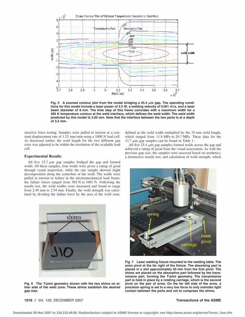
Fig. 5 A zoomed contour plot from the modtions for this model include a laser power of 2beam diameter of 8 mm. The time step of th485 K temperature contour at the weld interfacpredicted by this model is 3.00 mm. Note thatof 3.2 mm.
ig. 6 The T-joint geometry shown with the two shims on ei-her side of the weld zone. These shims establish the desired
ap size.016 / Vol. 129, DECEMBER 2007
aded 28 Nov 2007 to 130.215.49.80. Redistribution subject to ASME
defined as the weld width multiplied by the 19 mm weld length,which ranged from 11.8 MPa to 20.7 MPa. These data for the12.7 �m gap samples can be found in Table 1.
All five 25.4 �m gap samples formed welds across the gap andachieved a rating of good from the visual assessment. As with theprevious gap size, the samples were assessed based on aesthetics,a destructive tensile test, and calculation of weld strength, which
ridging a 25.4 �m gap. The operating condi-, a welding velocity of 0.001 m/s, and a laser
rame coincides with a maximum width for awhich defines the weld width. The weld widthinterface between the two parts is at a depth
Fig. 7 Laser welding fixture mounted to the welding table. Thearms pivot at the far right of the fixture. The absorbing part isplaced in a slot approximately 50 mm from the first pivot. Theshims are placed on the absorptive part followed by the trans-missive part, forming the T-joint geometry. The transmissivepart is held in place by a rotating carriage, which is the secondpivot on the pair of arms. On the far left side of the arms, aprecision spring is set to a very low force to only maintain light
el b.5 Wis fe,the
contact between the parts and not to compress the shims.
Transactions of the ASME
license or copyright; see http://www.asme.org/terms/Terms_Use.cfm
ar41
D
buwsewtcorfv
fpca1c�0wohtpcpa
atsaTkld
Tr
Tw
J
Downlo
re tabulated in Table 2. The failure force from the tensile testanged from 367 N to 584 N. The weld width ranged from.22 mm to 4.24 mm. The calculated weld strength across the1 mm long weld ranged from 7.9 MPa to 12.6 MPa.
iscussionThe experimental work above demonstrates that gaps can be
ridged in LTW and that the operating parameters can be designedsing a comprehensive two-dimensional modeling. The createdelds were aesthetically pleasing, consistent across a small
ample size, and had substantial failure strength. Note that despitefforts to minimize noise variables in the experiment, significanteld strength variation was found. This is likely due to the tensile
est procedure, where slight misalignment in the grip and fixturean result in unequal loading of the weld. In comparison withperating without a gap, creating a successful weld across a gapequires the welding velocity to be drastically decreased to allowor thermal diffusion and the line energy to be decreased to pre-ent decomposition.
In previously described work �1,3�, successful welds wereormed at velocities up to 0.07 m/s �2.76 in./ s� when no gap wasresent. This welding velocity could be further increased by in-reasing the laser intensity, which is defined by the laser powernd beam diameter. As described in this paper, bridging a2.7 �m �0.0005 in.� gap required the weld velocity to be de-reased to 0.0025 m/s �0.10 in./ s�. To bridge a 25.4 �m0.001 in.� gap, a further decrease in the laser velocity to.001 m/s �0.039 in./ s� is required. The significant decrease inelding velocity is needed to allow time for heat diffusion toccur within the absorptive part. Previous work found that duringigh-velocity gap-free welding situations, the maximum tempera-ure typically occurs slightly below the surface of the absorptiveart, with a significant decreasing temperature gradient with in-reasing depth �1,2�. The longer weld times demonstrated in thisaper decrease the temperature gradient and enable more of thebsorptive material to expand, bridging the gap.
From the three assessment techniques of the welds formedcross a gap, visual appearance, weld strength, and weld width,he overall outcome was quite positive. Visually, nine of the tenamples were given a visually good rating, while the other showedslight area of decomposition along the centerline of the weld.he weld length for the two different gap sizes was different, toeep the required failure force within the capacity of the availableoad frame. While the failure forces cannot be compared directlyue to these differences in weld area, the weld strength can be
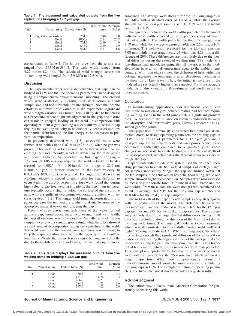
able 1 The measured and calculated outputs from the fiveeplications bridging a 12.7 �m gap
Trial Visual rating Failure force �N�Weld width
�mm�Strength
�MPa�
1 Slight decomposition 704.6 2.46 15.02 Good 1000.8 2.54 20.73 Good 705.5 2.49 14.94 Good 848.7 2.49 17.95 Good 564.9 2.51 11.8
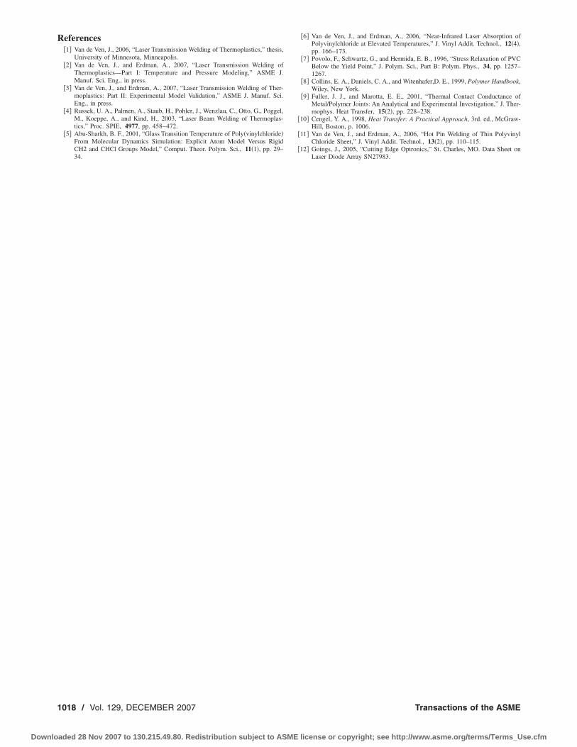
able 2 This table displays the measured outputs from fiveelding samples bridging a 25.4 �m gap
Trial Visual rating Failure force �N�Weld width
�mm�Strength
�MPa�
11 Good 480.9 4.24 10.312 Good 431.6 4.24 9.313 Good 466.6 4.22 10.114 Good 584.1 4.22 12.615 Good 367.0 4.22 7.9
ournal of Manufacturing Science and Engineering
aded 28 Nov 2007 to 130.215.49.80. Redistribution subject to ASME
compared. The average weld strength for the 12.7 �m samples is16.1 MPa with a standard error of 1.5 MPa, while the averagestrength for the 25.4 �m samples is 10.0 MPa with a standarderror of 0.8 MPa.
The agreement between the weld widths predicted by the modelwith the weld width achieved in the experiments was adequate,but not excellent. The width predicted for the 12.7 �m gap was2.10 mm, while the average measured width was 2.50 mm, a 16%difference. The weld width predicted for the 25.4 �m gap was3.00 mm, while the average measured width was 4.23 mm, a dif-ference of 29%. These differences are most likely due to the ther-mal diffusion during the extended welding time. The model is atwo-dimensional model, assuming that all the nodes in the mod-eled plane have an initial temperature equal to the ambient tem-perature. With long elapse times, the diffusion of heat within thepolymer increases the temperature in all directions, including inthe direction of laser travel. Thus, the initial temperature in themodeled area is actually higher than expected. For more accuratemodeling of this situation, a three-dimensional model might bemore appropriate.
ConclusionIn manufacturing applications, poor dimensional control can
lead to the formation of gaps between mating part features requir-ing welding. Gaps in the weld joint create a significant problemfor LTW because of the reliance on contact conduction betweenthe absorptive and transmissive parts. Previous research has as-sumed gap-free joints.
This paper uses a previously constructed two-dimensional nu-merical model to design operating parameters for bridging gaps inLTW. In the design of parameters for a 12.7 �m gap and a25.4 �m gap, the welding velocity and laser power needed to bedecreased significantly compared to a gap-free joint. Thesechanges are necessary to create heating into a sufficient depth ofthe absorptive part, which creates the thermal strain necessary tobridge the gap.
Experiments with a diode laser system used the designed oper-ating parameters to create five welded samples of each gap size.All samples successfully bridged the gap and formed welds. Ofthe ten samples, nine achieved an aesthetic good rating, while onesample showed slight decomposition. Samples were also assessedby measuring the tensile force at failure in a load frame and theweld width. From these data, the weld strength was calculated andfound to average 16.1 MPa for the 12.7 �m gap samples and10.0 MPa for the 25.4 �m gap samples.
The weld width of the experimental samples adequately agreedwith the predictions of the model. The difference between themeasured width and the predicted width was 16% for the 12.7 �mgap samples and 29% for the 25.4 �m gap samples. This discrep-ancy is likely due to the large thermal diffusion occurring in alldirections, including along the direction of the laser travel due tothe long weld times. The numerical model is two-dimensional,which was demonstrated to successfully predict weld widths athigher welding velocities �1,3�. When bridging gaps, the elapsetime is long enough that significant diffusion of the absorbed ra-diation occurs, heating the regions in front of the laser path. As thelaser travels along the path, the area being irradiated is at a higherinitial temperature, which results in a wider weld than predicted.This concept is supported by the fact that the error in the predictedweld width is greater for the 25.4 �m trial, which required alonger elapse time. While more computationally intensive, athree-dimensional model would be more accurate in simulatingbridging gaps in LTW. For a rough estimation of operating param-eters, the two-dimensional model provides adequate results.
AcknowledgmentThe authors would like to thank Andersen Corporation for gen-
erously sponsoring this work.
DECEMBER 2007, Vol. 129 / 1017
license or copyright; see http://www.asme.org/terms/Terms_Use.cfm
R
1
Downlo
eferences�1� Van de Ven, J., 2006, “Laser Transmission Welding of Thermoplastics,” thesis,
University of Minnesota, Minneapolis.�2� Van de Ven, J., and Erdman, A., 2007, “Laser Transmission Welding of
Thermoplastics—Part I: Temperature and Pressure Modeling,” ASME J.Manuf. Sci. Eng., in press.
�3� Van de Ven, J., and Erdman, A., 2007, “Laser Transmission Welding of Ther-moplastics: Part II: Experimental Model Validation,” ASME J. Manuf. Sci.Eng., in press.
�4� Russek, U. A., Palmen, A., Staub, H., Pohler, J., Wenzlau, C., Otto, G., Poggel,M., Koeppe, A., and Kind, H., 2003, “Laser Beam Welding of Thermoplas-tics,” Proc. SPIE, 4977, pp. 458–472.
�5� Abu-Sharkh, B. F., 2001, “Glass Transition Temperature of Poly�vinylchloride�From Molecular Dynamics Simulation: Explicit Atom Model Versus RigidCH2 and CHCl Groups Model,” Comput. Theor. Polym. Sci., 11�1�, pp. 29–34.
018 / Vol. 129, DECEMBER 2007
aded 28 Nov 2007 to 130.215.49.80. Redistribution subject to ASME
�6� Van de Ven, J., and Erdman, A., 2006, “Near-Infrared Laser Absorption ofPolyvinylchloride at Elevated Temperatures,” J. Vinyl Addit. Technol., 12�4�,pp. 166–173.
�7� Povolo, F., Schwartz, G., and Hermida, E. B., 1996, “Stress Relaxation of PVCBelow the Yield Point,” J. Polym. Sci., Part B: Polym. Phys., 34, pp. 1257–1267.
�8� Collins, E. A., Daniels, C. A., and Witenhafer,D. E., 1999, Polymer Handbook,Wiley, New York.
�9� Fuller, J. J., and Marotta, E. E., 2001, “Thermal Contact Conductance ofMetal/Polymer Joints: An Analytical and Experimental Investigation,” J. Ther-mophys. Heat Transfer, 15�2�, pp. 228–238.
�10� Cengel, Y. A., 1998, Heat Transfer: A Practical Approach, 3rd. ed., McGraw-Hill, Boston, p. 1006.
�11� Van de Ven, J., and Erdman, A., 2006, “Hot Pin Welding of Thin PolyvinylChloride Sheet,” J. Vinyl Addit. Technol., 13�2�, pp. 110–115.
�12� Goings, J., 2005, “Cutting Edge Optronics,” St. Charles, MO. Data Sheet onLaser Diode Array SN27983.
Transactions of the ASME
license or copyright; see http://www.asme.org/terms/Terms_Use.cfm