Embed Size (px)
Citation preview


will expand on the thermal design aspects of Overture ICs. While the bridge/parallel configurationis only one of many that can be made to obtain higher output power levels, the concept of "designby power dissipation" is equally applicable to other types of booster circuits.
The BPA-200 schematics, and test results exemplify what can be achieved with proper componentselection, thermal design, and layout techniques. The BPA-200 is only an example and is notintended for sale. This documentation is intended to show obtainable results and give generalguidance of conceptual design.
III. Thermal Background:The voltage and current ratings of a power semiconductor are typically the first specs considered indesigning high power amplifiers. The same is true for an integrated monolithic power amplifier.However, power dissipation ratings are equally important to the long-term reliability of the poweramplifier design. When using a monolithic IC in its intended application and within its specifiedcapabilities, the thermal design is relatively straightforward. When an IC is used beyond itscapabilities, as in booster circuits, power dissipation issues become more critical and not asstraight- forward. Therefore, the designer must understand the IC's power dissipation capabilitiesbefore using the IC in a booster configuration.
-Typical Characteristic DataThe power dissipation capabilities of a power IC are either specified in the datasheet or can bederived from its guaranteed output power specification. While the power dissipation rating for theLM3886T is 125W, this number can be misleading. Its power dissipation specification is derivedfrom the IC's junction-to-case thermal resistance, ØJC=l °C/W, the maximum junctiontemperature, TJ=150°C, and the ambient air, TA=25°C. As stated in the datasheet, the device mustbe derated based on these parameters while operating at elevated temperatures. The heatsinkingrequirements for the application are based on these parameters so that the IC will not go intoThermal Shutdown (TSD). The real problem for Overture ICs, however, comes from thesensitivity of the output stage's unique SPiKe Protection which dynamically monitors the outputtransistor's temperature. While the thermal shutdown circuitry is enabled at TJ=150°C, SPiKecircuitry is enabled at TJ=250°C for instantaneous power spikes in the output stage transistor. Asthe overall temperature of the IC increases, SPiKe circuitry becomes even more sensitive causing itto turn on before the 125W limit is reached. TSD circuitry will continue to function globally forthe IC in conjunction with SPiKe circuitry. However, protection circuitry should not be activatedunder normal operating conditions. The question then becomes, what is the power dissipationlimit for the IC such that SPiKe circuitry is not enabled? Knowing the power dissipation limit andkeeping the case temperature of the IC as cool as possible will expand the output power capabilitywithout activating SPiKe Protection.
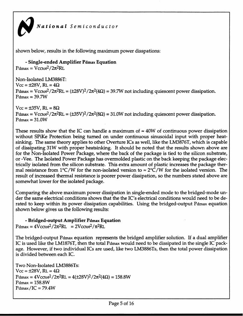
The other way to determine IC power dissipation capabilities is to analyze the output powerspecification in the datasheet. In the case of the LM3886T, there are two output powerspecification guarantees: 60W(min) into a 4Ω load using ±28V supplies and 50W(typ) into an 8Ωload from ±35V supplies. Using these two conditions and the theoretical maximum powerdissipation equation
Page 4 of 16