Embed Size (px)
Citation preview
GOVERNMENT OF INDIA MINISTRY OF RAILWAYS
(Railway Board)
BRIDGE RULES (IN SI UNITS)
RULES SPECIFYING THE LOADS FOR DESIGN OF SUPER-STRUCTURE AND SUB-STRUCTURE OF BRIDGES AND FOR ASSESSMENT OF THE STRENGTH OF
EXISTING BRIDGES
ADOPTED –1941 FIRST REVISION - 1964
First Reprinting - 1989 Second Reprinting - 2008 Third Reprinting - 2014
(Incorporating Correction Slips Upto 49)
ISSUED BY
RESEARCH DESIGNS AND STANDARDS ORGANISATION LUCKNOW - 226011
Disclaimer: This Compilation is for educational reference only. For details refer original correction slips.
i
CONTENTS
Sl. No. Description Page No.
1. Scope. 1
2. Loads. 1
2.1 Loads to be taken into account. 1
2.2 Dead load. 2
2.3 Live load. 2
2.4 Dynamic effect. 7
2.5 Forces due to curvature and eccentricity of track. 9
2.6 Temperature effect. 9
2.7 Frictional resistance of expansion bearings. 10
2.8 Longitudinal forces. 10
2.9 Racking force. 13
2.10 Forces on parapets. 13
2.11 Wind pressure effect. 13
2.12 Forces and effects due to earthquake. 14
2.13 Erection forces and effects. 19
2.14 Derailment loads. 19
2.15 Load due to Plasser’s Quick Relay System (PQRS). 19
3. Rules for assessing the strength of existing Railway Bridges. 19
4. Critical speed. 20
5. Details of old standard loadings for Bridges. 21
APPENDICES
Appendix No. Description Page Nos.
Appendix-I
(Sheet 1)
762mm Gauge ‘H’ Class Loading. 23
Appendix-I
(Sheet 2)
762mm Gauge ‘A’ Class Loading. 24
Appendix-I
(Sheet 3)
762mm Gauge ‘B’ Class Loading. 25
Appendix-II EUDL in kN (t) on each track and CDA values for 762mm Gauge
bridges.
26
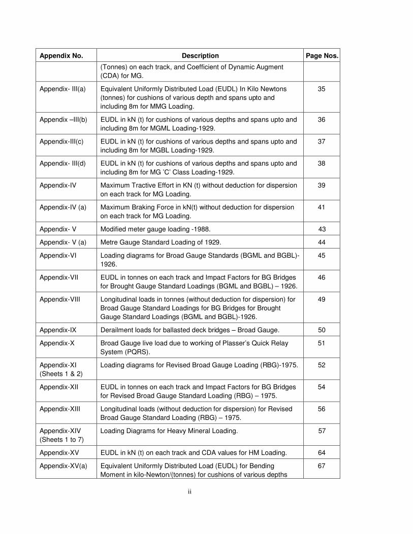
Appendix- III Equivalent Uniformly Distributed Loads (EUDL) in Kilo Newtons 30
ii
Appendix No. Description Page Nos.
(Tonnes) on each track, and Coefficient of Dynamic Augment
(CDA) for MG.
Appendix- III(a) Equivalent Uniformly Distributed Load (EUDL) In Kilo Newtons
(tonnes) for cushions of various depth and spans upto and
including 8m for MMG Loading.
35
Appendix –III(b) EUDL in kN (t) for cushions of various depths and spans upto and
including 8m for MGML Loading-1929.
36
Appendix-III(c) EUDL in kN (t) for cushions of various depths and spans upto and
including 8m for MGBL Loading-1929.
37
Appendix- III(d) EUDL in kN (t) for cushions of various depths and spans upto and
including 8m for MG ’C’ Class Loading-1929.
38
Appendix-IV Maximum Tractive Effort in KN (t) without deduction for dispersion
on each track for MG Loading.
39
Appendix-IV (a) Maximum Braking Force in kN(t) without deduction for dispersion
on each track for MG Loading.
41
Appendix- V Modified meter gauge loading -1988. 43
Appendix- V (a) Metre Gauge Standard Loading of 1929. 44
Appendix-VI Loading diagrams for Broad Gauge Standards (BGML and BGBL)-
1926.
45
Appendix-VII EUDL in tonnes on each track and Impact Factors for BG Bridges
for Brought Gauge Standard Loadings (BGML and BGBL) – 1926.
46
Appendix-VIII Longitudinal loads in tonnes (without deduction for dispersion) for
Broad Gauge Standard Loadings for BG Bridges for Brought
Gauge Standard Loadings (BGML and BGBL)-1926.
49
Appendix-IX Derailment loads for ballasted deck bridges – Broad Gauge. 50
Appendix-X Broad Gauge live load due to working of Plasser’s Quick Relay
System (PQRS).
51
Appendix-XI
(Sheets 1 & 2)
Loading diagrams for Revised Broad Gauge Loading (RBG)-1975. 52
Appendix-XII EUDL in tonnes on each track and Impact Factors for BG Bridges
for Revised Broad Gauge Standard Loading (RBG) – 1975.
54
Appendix-XIII Longitudinal loads (without deduction for dispersion) for Revised
Broad Gauge Standard Loading (RBG) – 1975.
56
Appendix-XIV
(Sheets 1 to 7)
Loading Diagrams for Heavy Mineral Loading. 57
Appendix-XV EUDL in kN (t) on each track and CDA values for HM Loading. 64
Appendix-XV(a) Equivalent Uniformly Distributed Load (EUDL) for Bending
Moment in kilo-Newton/(tonnes) for cushions of various depths
67
iii
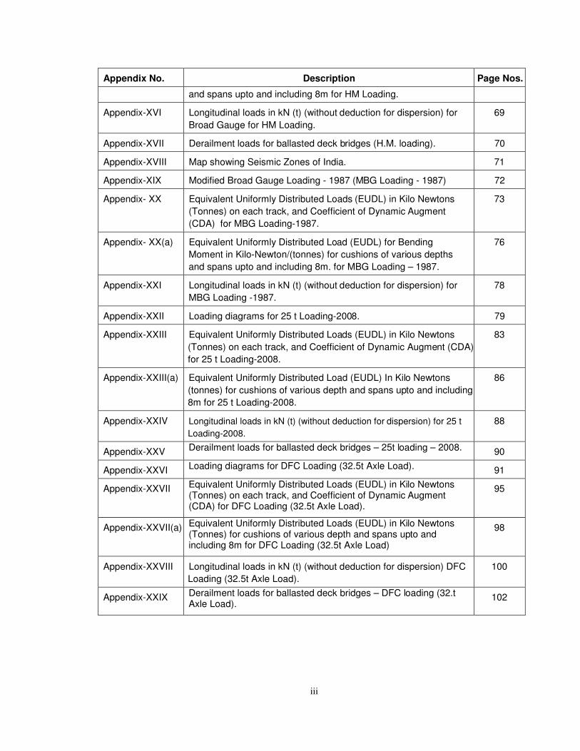
Appendix No. Description Page Nos.
and spans upto and including 8m for HM Loading.
Appendix-XVI Longitudinal loads in kN (t) (without deduction for dispersion) for
Broad Gauge for HM Loading.
69
Appendix-XVII Derailment loads for ballasted deck bridges (H.M. loading). 70
Appendix-XVIII Map showing Seismic Zones of India. 71
Appendix-XIX Modified Broad Gauge Loading - 1987 (MBG Loading - 1987) 72
Appendix- XX Equivalent Uniformly Distributed Loads (EUDL) in Kilo Newtons
(Tonnes) on each track, and Coefficient of Dynamic Augment
(CDA) for MBG Loading-1987.
73
Appendix- XX(a) Equivalent Uniformly Distributed Load (EUDL) for Bending
Moment in Kilo-Newton/(tonnes) for cushions of various depths
and spans upto and including 8m. for MBG Loading – 1987.
76
Appendix-XXI Longitudinal loads in kN (t) (without deduction for dispersion) for
MBG Loading -1987.
78
Appendix-XXII Loading diagrams for 25 t Loading-2008. 79
Appendix-XXIII Equivalent Uniformly Distributed Loads (EUDL) in Kilo Newtons
(Tonnes) on each track, and Coefficient of Dynamic Augment (CDA)
for 25 t Loading-2008.
83
Appendix-XXIII(a) Equivalent Uniformly Distributed Load (EUDL) In Kilo Newtons
(tonnes) for cushions of various depth and spans upto and including
8m for 25 t Loading-2008.
86
Appendix-XXIV Longitudinal loads in kN (t) (without deduction for dispersion) for 25 t
Loading-2008.
88
Appendix-XXV Derailment loads for ballasted deck bridges – 25t loading – 2008. 90
Appendix-XXVI Loading diagrams for DFC Loading (32.5t Axle Load). 91
Appendix-XXVII Equivalent Uniformly Distributed Loads (EUDL) in Kilo Newtons (Tonnes) on each track, and Coefficient of Dynamic Augment (CDA) for DFC Loading (32.5t Axle Load).
95
Appendix-XXVII(a) Equivalent Uniformly Distributed Loads (EUDL) in Kilo Newtons (Tonnes) for cushions of various depth and spans upto and including 8m for DFC Loading (32.5t Axle Load)
98
Appendix-XXVIII Longitudinal loads in kN (t) (without deduction for dispersion) DFC
Loading (32.5t Axle Load).
100
Appendix-XXIX Derailment loads for ballasted deck bridges – DFC loading (32.t Axle Load).
102
1
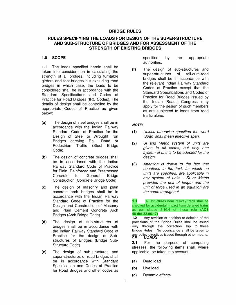
BRIDGE RULES
RULES SPECIFYING THE LOADS FOR DESIGN OF THE SUPER-STRUCTURE AND SUB-STRUCTURE OF BRIDGES AND FOR ASSESSMENT OF THE
STRENGTH OF EXISTING BRIDGES
1.0 SCOPE
1.1 The loads specified herein shall be
taken into consideration in calculating the
strength of all bridges, including turntable
girders and foot-bridges but excluding road
bridges in which case, the loads to be
considered shall be in accordance with the
Standard Specifications and Codes of
Practice for Road Bridges (IRC Codes). The
details of design shall be controlled by the
appropriate Codes of Practice as given
below:
(a) The design of steel bridges shall be in
accordance with the Indian Railway
Standard Code of Practice for the
Design of Steel or Wrought Iron
Bridges carrying Rail, Road or
Pedestrian Traffic (Steel Bridge
Code).
(b) The design of concrete bridges shall
be in accordance with the Indian
Railway Standard Code of Practice
for Plain, Reinforced and Prestressed
Concrete for General Bridge
Construction (Concrete Bridge Code).
(c) The design of masonry and plain
concrete arch bridges shall be in
accordance with the Indian Railway
Standard Code of Practice for the
Design and Construction of Masonry
and Plain Cement Concrete Arch
Bridges (Arch Bridge Code).
(d) The design of sub-structures of
bridges shall be in accordance with
the Indian Railway Standard Code of
Practice for the design of Sub-
structures of Bridges (Bridge Sub-
Structure Code).
(e) The design of sub-structures and
super-structures of road bridges shall
be in accordance with Standard
Specification and Codes of Practice
for Road Bridges and other codes as
specified by the appropriate
authorities.
(f) The design of sub-structures and
super-structures of rail-cum-road
bridges shall be in accordance with
the relevant Indian Railway Standard
Codes of Practice except that the
Standard Specifications and Codes of
Practice for Road Bridges issued by
the Indian Roads Congress may
apply for the design of such members
as are subjected to loads from road
traffic alone.
NOTE:
(1) Unless otherwise specified the word
‘Span’ shall mean effective span.
(2) SI and Metric system of units are
given in all cases, but only one
system of unit is to be adopted for the
design.
(3) Attention is drawn to the fact that
equations in the text, for which no
units are specified, are applicable in
any system of units - SI or Metric
provided the unit of length and the
unit of force used in an equation are
the same throughout.
1.1 All structures near railway track shall be checked for accidental impact from derailed trains as per clause 2.16.4 of these rule (ACS 48 dtd.22.06.17)1.2 Any revision or addition or deletion of the
provisions of the Bridge Rules shall be issued
only through the correction slip to these
Bridge Rules. No cognizance shall be given to
any policy directives issued through other means. 2.0 LOADS
2.1 For the purpose of computing
stresses, the following items shall, where
applicable, be taken into account:
(a) Dead load
(b) Live load
(c) Dynamic effects
2
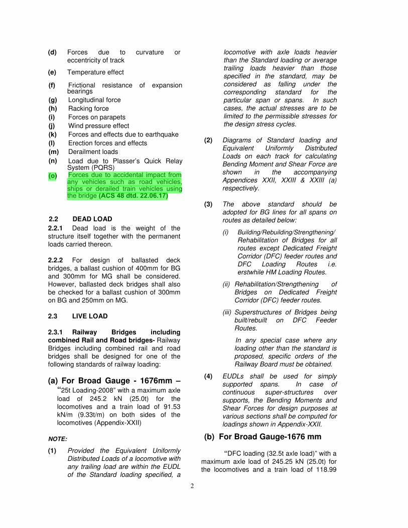
(d) Forces due to curvature or
eccentricity of track
(e) Temperature effect
(f) Frictional resistance of expansionbearings
(g) Longitudinal force
(h) Racking force
(i) Forces on parapets
(j) Wind pressure effect
(k) Forces and effects due to earthquake
(l) Erection forces and effects
(m) Derailment loads
(n)
(o)
Load due to Plasser’s Quick RelaySystem (PQRS)Forces due to accidental impact from any vehicles such as road vehicles, ships or derailed train vehicles using the bridge (ACS 48 dtd. 22.06.17)
2.2 DEAD LOAD
2.2.1 Dead load is the weight of the
structure itself together with the permanent
loads carried thereon.
2.2.2 For design of ballasted deck
bridges, a ballast cushion of 400mm for BG
and 300mm for MG shall be considered.
However, ballasted deck bridges shall also
be checked for a ballast cushion of 300mm
on BG and 250mm on MG.
2.3 LIVE LOAD
2.3.1 Railway Bridges including
combined Rail and Road bridges- Railway
Bridges including combined rail and road
bridges shall be designed for one of the
following standards of railway loading:
(a) For Broad Gauge - 1676mm –“25t Loading-2008” with a maximum axle
load of 245.2 kN (25.0t) for the
locomotives and a train load of 91.53
kN/m (9.33t/m) on both sides of the
locomotives (Appendix-XXII)
NOTE:
(1) Provided the Equivalent Uniformly
Distributed Loads of a locomotive with
any trailing load are within the EUDL
of the Standard loading specified, a
locomotive with axle loads heavier
than the Standard loading or average
trailing loads heavier than those
specified in the standard, may be
considered as falling under the
corresponding standard for the
particular span or spans. In such
cases, the actual stresses are to be
limited to the permissible stresses for
the design stress cycles.
(2) Diagrams of Standard loading and
Equivalent Uniformly Distributed
Loads on each track for calculating
Bending Moment and Shear Force are
shown in the accompanying
Appendices XXII, XXIII & XXIII (a)
respectively.
(3) The above standard should be
adopted for BG lines for all spans on
routes as detailed below:
(i) Building/Rebuilding/Strengthening/
Rehabilitation of Bridges for all
routes except Dedicated Freight
Corridor (DFC) feeder routes and
DFC Loading Routes i.e.
erstwhile HM Loading Routes.
(ii) Rehabilitation/Strengthening of
Bridges on Dedicated Freight
Corridor (DFC) feeder routes.
(iii) Superstructures of Bridges being
built/rebuilt on DFC Feeder
Routes.
In any special case where any
loading other than the standard is
proposed, specific orders of the
Railway Board must be obtained.
(4) EUDLs shall be used for simply
supported spans. In case of
continuous super-structures over
supports, the Bending Moments and
Shear Forces for design purposes at
various sections shall be computed for
loadings shown in Appendix-XXII.
(b) For Broad Gauge-1676 mm
“DFC loading (32.5t axle load)” with a
maximum axle load of 245.25 kN (25.0t) for
the locomotives and a train load of 118.99
3
kN/m (12.13t/m) on both sides of the
locomotives (Appendix-XXVI). The maximum axle load of wagons are 318.825 kN (32.5t).
NOTE:
(1) Provided the Equivalent Uniformly
Distributed Loads of a locomotive with
any trailing load are within the EUDL
of the Standard loading specified, a
locomotive with axle loads heavier
than the Standard loading or average
trailing loads heavier than those
specified in the standard, may be
considered as falling under the
corresponding standard for the
particular span or spans. In such
cases, the actual stresses are to be
limited to the permissible stresses for the design stress cycles.
(2) Diagrams of Standard loading and
Equivalent Uniformly Distributed
Loads on each track for calculating
Bending Moment and Shear Force for
“DFC loading (32.5t axle load)” are
given in the accompanying
Appendices XXVI, XXVII & XXVII (a)
respectively.
(3) (i) The above standard should be
adopted for bridges on identified
routes approved by Railway
Board.
(ii) Building/Rebuilding/Strengthening/
Rehabilitation of bridges on DFC
Loading Route i.e. erstwhile HM
Loading Routes.
(iii) Besides this, the above standard
should be adopted for Building/
rebuilding of substructure ONLY
on Dedicated Freight Corridor
(DFC) Feeder Routes. For
rebuilding of super structure on
Dedicated Freight Corridor (DFC)
Feeder Routes, refer note no. 3(iii)
of clause No. 2.3.1(a).
(4) EUDLs shall be used for simply
supported spans. In case of
continuous super-structures over
supports, the Bending Moments and
Shear Forces for design purposes at
various sections shall be computed for
loadings shown in Appendix-XXVI.
(c) For Metre Gauge-1000mm
(i) Modified Metre Gauge Loading-1988
with maximum axle load of 156.9 kN
(16.0 t) for locomotives and a train
load of 53.9 kN (5.5t) per metre on
both sides of locomotives with
maximum axle load of 137.29 kN
(14.0t) for the trainload.
(ii) Standard M.L. of 1929 for 129.4 kN
(13.2t) axle loads and a train load of
37.95 kN (3.87t) per metre behind the
engines.
(iii) Standard B.L. of 1929 for 104.9 kN
(10.7 t) axle loads and a train load of
37.95 kN (3.87 t) per metre behind the
engines.
(iv) Standard C of 1929 for 79.4 kN (8.1 t)
axle loads and a train load of 37.95 kN
(3.87 t) per metre behind the engines.
NOTE:
(1) Provided the Equivalent Uniformly
Distributed Loads of a locomotive with
any trailing load are within the EUDL
of the Standard loading specified, a
locomotive with axle loads heavier
than the standard loading or average
trailing loads heavier than those
specified in the standard may be
considered as falling under the
corresponding standards for the
particular span or spans. In such
cases, the actual stresses are to be
limited to the permissible stresses for
the design stress cycles.
(2) Diagrams of standard loadings are
shown in Appendices V and V (a).
EUDL, on each track for calculating
Bending Moment and Shear, in kN (t)
are given in Appendix III. EUDL for
Bending Moment/Shear Force in kN
(t) for cushion of various depths and
spans upto and including 8m are
given in Appendices III (a), III (b),
III(c) and III (d), for various Metre
Gauge Standard Loadings.
4
(3) Modified Metre Gauge Loading-1988–
This standard will apply while
constructing new bridges or
rebuilding/strengthening of existing
bridges on the Metre Gauge routes,
where the running, of heavier freight
wagons and more powerful locos is
envisaged, besides those which are
identified for upgradation.
(4) Main Line Standards – For such Main
Lines where Modified MG Loading-
1988 is not required, ML standards
should be adopted.
(5) Branch Line Standard - Branch Lines
which are obviously never likely to be
other than Branch Lines, should have
all bridges built to BL standard of
loading unless the branch be in a
heavy mineral area in which case the
provision of Note (3) above should be
adopted.
(6) EUDLs shall be used for simply
supported spans. In case of
continuous super-structure over
supports, the Bending Moments and
Shear Forces for design purposes at
various sections shall be computed
for loadings shown in Appendices V
and V (a).
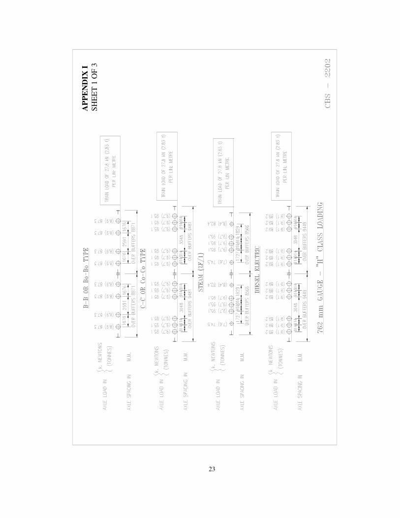
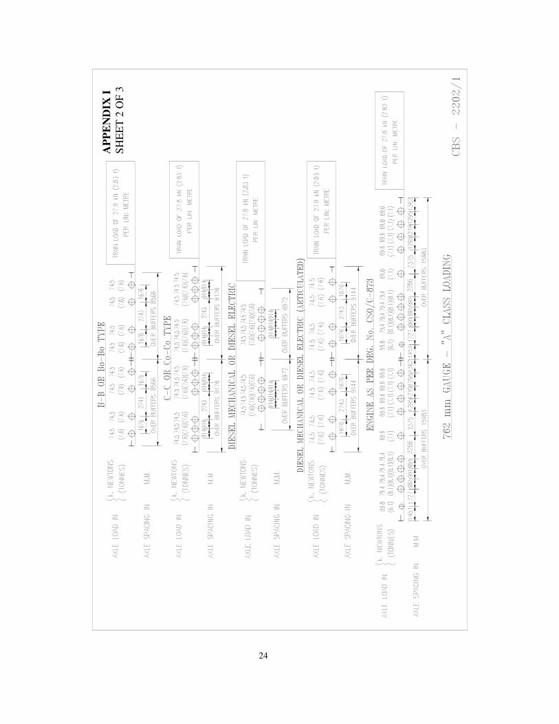
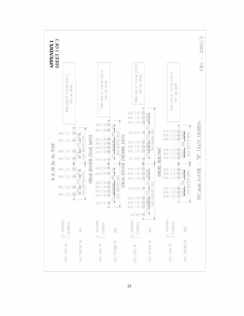
(d) For Narrow Gauge-762 mm
(i) 'H' (Heavy) class loading with a
maximum axle load of 95.1 kN (9.7 t)
and a train load of 27.8 kN (2.83 t)
per metre behind the engines.
(ii) 'A' class Main Line loading with a
maximum axle load of 79.4 kN (8.1 t)
and a train load of 27.8 kN (2.83 t)
per metre behind the engines.
(iii) 'B' class Branch Line loading with a
maximum axle load of 59.8 kN (6.1 t)
and a train load of 27.8 kN (2.83 t)
per metre behind the engines.
NOTE:
Diagrams of Standard loading and
Equivalent Uniformly Distributed
Loads on each track for calculating
Bending Moment and Shear Force
are shown in the accompanying
Appendices I & II.
(e) For Narrow Gauge-610mm
The Standard will be specified by the
Railway Board from time to time.
2.3.1.1 For analysis and design of the new bridges, the EUDL approach shall be used. However, exact analysis for maximum Bending Moment and Shear Forces can also be carried out with the help of software "Moving Load" issued by RDSO.
2.3.2 Footbridges and footpaths on
Bridges
2.3.2.1 The live load due to pedestrian
traffic shall be treated as uniformly
distributed over the footway. For the design
of footbridges or footpaths on railway
bridges the live load including dynamic
effects shall be taken as 4.8 kPa (490
kg/m2) of the footpath area. For the design
of foot-path on a road bridge or road rail
bridge, the live load including dynamic
effects may be taken as 4.07 kPa (415
kg/m2) except that, where crowd loading is
likely, this may be increased to 4.8 kPa (490
kg/m2).
2.3.2.2 Where footpaths are provided on a
road or Railway Bridge the load on footpath
for the purpose of designing the main
girders shall be taken as follows:
(a) For effective spans of 7.5m or less
4.07 kPa (415 kg/m2).
(b) For effective spans over 7.5m but not
exceeding 30m - an intensity of load
reducing uniformly from 4.07 kPa
(415 kg/m2) for a span of 7.5m to 2.89
kPa (295 kg/m2) for a span of 30m.
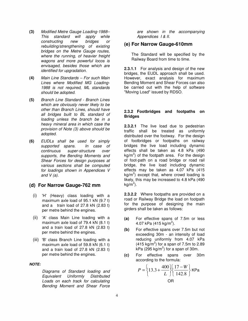
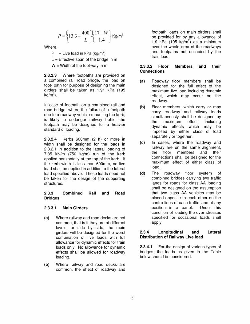
(c) For effective spans over 30m
according to the formula:
−
+=8.142
174003.13
W
LP KPa
OR
5
−
+=4.1
174003.13
W
LP Kg/m
2
Where,
P = Live load in kPa (kg/m2)
L = Effective span of the bridge in m
W = Width of the foot-way in m
2.3.2.3 Where footpaths are provided on
a combined rail road bridge, the load on
foot- path for purpose of designing the main
girders shall be taken as 1.91 kPa (195
kg/m2).
In case of footpath on a combined rail and
road bridge, where the failure of a footpath
due to a roadway vehicle mounting the kerb,
is likely to endanger railway traffic, the
footpath may be designed for a heavier
standard of loading.
2.3.2.4 Kerbs 600mm (2 ft) or more in
width shall be designed for the loads in
2.3.2.1 in addition to the lateral loading of
7.35 kN/m (750 kg/m) run of the kerb
applied horizontally at the top of the kerb. If
the kerb width is less than 600mm, no live
load shall be applied in addition to the lateral
load specified above. These loads need not
be taken for the design of the supporting
structures.
2.3.3 Combined Rail and Road
Bridges
2.3.3.1 Main Girders
(a) Where railway and road decks are not
common, that is if they are at different
levels, or side by side, the main
girders will be designed for the worst
combination of live loads with full
allowance for dynamic effects for train
loads only. No allowance for dynamic
effects shall be allowed for roadway
loading.
(b) Where railway and road decks are
common, the effect of roadway and
footpath loads on main girders shall
be provided for by any allowance of
1.9 kPa (195 kg/m2) as a minimum
over the whole area of the roadways
and footpaths not occupied by the
train load.
2.3.3.2 Floor Members and their
Connections
(a) Roadway floor members shall be
designed for the full effect of the
maximum live load including dynamic
effect, which may occur on the
roadway.
(b) Floor members, which carry or may
carry roadway and railway loads
simultaneously shall be designed by
the maximum effect, including
dynamic effects which may be
imposed by either class of load
separately or together.
(c) In cases, where the roadway and
railway are on the same alignment,
the floor members and their
connections shall be designed for the
maximum effect of either class of
load.
(d) The roadway floor system of
combined bridges carrying two traffic
lanes for roads for class AA loading
shall be designed on the assumption
that two class AA vehicles may be
placed opposite to each other on the
centre lines of each traffic lane at any
position in a panel. Under this
condition of loading the over stresses
specified for occasional loads shall
apply.
2.3.4 Longitudinal and Lateral
Distribution of Railway Live load
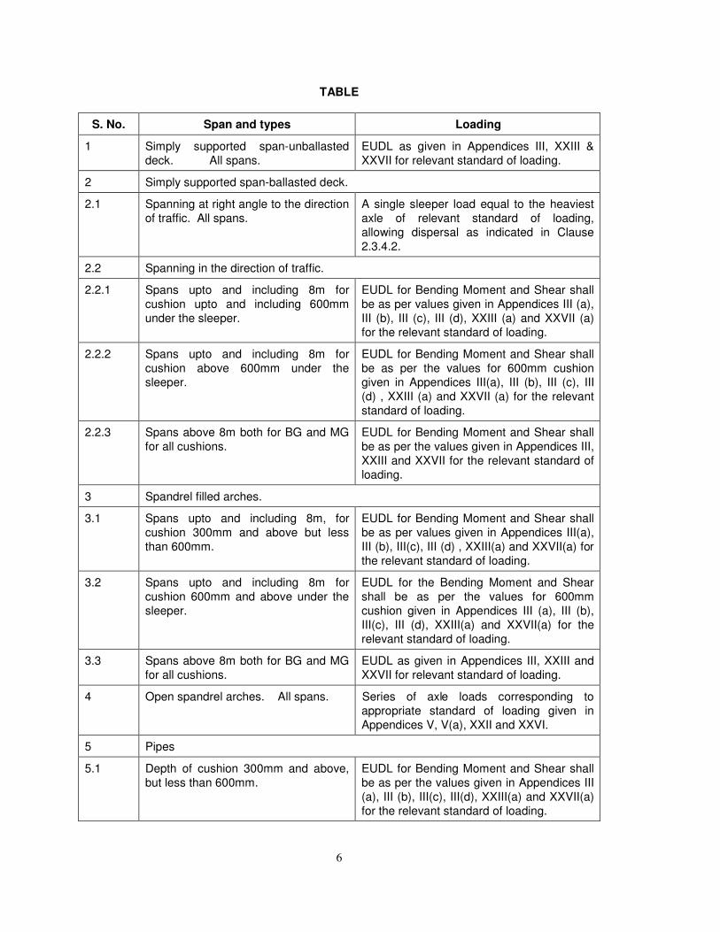
2.3.4.1 For the design of various types of
bridges, the loads as given in the Table
below should be considered.
6
TABLE
S. No. Span and types Loading
1 Simply supported span-unballasted
deck. All spans.
EUDL as given in Appendices III, XXIII &
XXVII for relevant standard of loading.
2 Simply supported span-ballasted deck.
2.1 Spanning at right angle to the direction
of traffic. All spans.
A single sleeper load equal to the heaviest
axle of relevant standard of loading,
allowing dispersal as indicated in Clause
2.3.4.2.
2.2 Spanning in the direction of traffic.
2.2.1 Spans upto and including 8m for
cushion upto and including 600mm
under the sleeper.
EUDL for Bending Moment and Shear shall
be as per values given in Appendices III (a),
III (b), III (c), III (d), XXIII (a) and XXVII (a)
for the relevant standard of loading.
2.2.2 Spans upto and including 8m for
cushion above 600mm under the
sleeper.
EUDL for Bending Moment and Shear shall
be as per the values for 600mm cushion
given in Appendices III(a), III (b), III (c), III
(d) , XXIII (a) and XXVII (a) for the relevant
standard of loading.
2.2.3 Spans above 8m both for BG and MG
for all cushions.
EUDL for Bending Moment and Shear shall
be as per the values given in Appendices III,
XXIII and XXVII for the relevant standard of
loading.
3 Spandrel filled arches.
3.1 Spans upto and including 8m, for
cushion 300mm and above but less
than 600mm.
EUDL for Bending Moment and Shear shall
be as per values given in Appendices III(a),
III (b), III(c), III (d) , XXIII(a) and XXVII(a) for
the relevant standard of loading.
3.2 Spans upto and including 8m for
cushion 600mm and above under the
sleeper.
EUDL for the Bending Moment and Shear
shall be as per the values for 600mm
cushion given in Appendices III (a), III (b),
III(c), III (d), XXIII(a) and XXVII(a) for the
relevant standard of loading.
3.3 Spans above 8m both for BG and MG
for all cushions.
EUDL as given in Appendices III, XXIII and
XXVII for relevant standard of loading.
4 Open spandrel arches. All spans. Series of axle loads corresponding to
appropriate standard of loading given in
Appendices V, V(a), XXII and XXVI.
5 Pipes
5.1 Depth of cushion 300mm and above,
but less than 600mm.
EUDL for Bending Moment and Shear shall
be as per the values given in Appendices III
(a), III (b), III(c), III(d), XXIII(a) and XXVII(a)
for the relevant standard of loading.
7
S. No. Span and types Loading
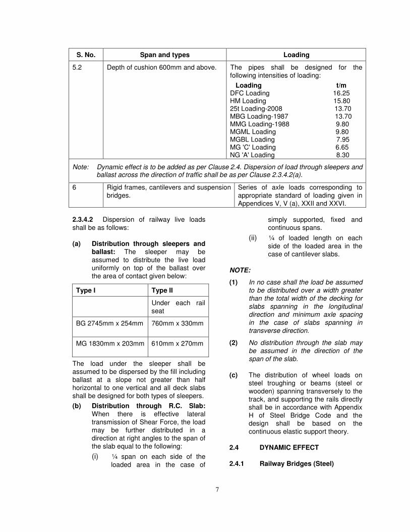
5.2 Depth of cushion 600mm and above. The pipes shall be designed for the
following intensities of loading:
Loading t/m DFC Loading 16.25 HM Loading 15.80 25t Loading-2008 13.70 MBG Loading-1987 13.70 MMG Loading-1988 9.80 MGML Loading 9.80 MGBL Loading 7.95 MG 'C' Loading 6.65 NG 'A' Loading 8.30
Note: Dynamic effect is to be added as per Clause 2.4. Dispersion of load through sleepers and ballast across the direction of traffic shall be as per Clause 2.3.4.2(a).
6 Rigid frames, cantilevers and suspension
bridges.
Series of axle loads corresponding to
appropriate standard of loading given in
Appendices V, V (a), XXII and XXVI.
2.3.4.2 Dispersion of railway live loads
shall be as follows:
(a) Distribution through sleepers and
ballast: The sleeper may be
assumed to distribute the live load
uniformly on top of the ballast over
the area of contact given below:
Type I Type II
Under each rail
seat
BG 2745mm x 254mm 760mm x 330mm
MG 1830mm x 203mm 610mm x 270mm
The load under the sleeper shall be
assumed to be dispersed by the fill including
ballast at a slope not greater than half
horizontal to one vertical and all deck slabs
shall be designed for both types of sleepers.
(b) Distribution through R.C. Slab:
When there is effective lateral
transmission of Shear Force, the load
may be further distributed in a
direction at right angles to the span of
the slab equal to the following:
(i) ¼ span on each side of the
loaded area in the case of
simply supported, fixed and
continuous spans.
(ii) ¼ of loaded length on each
side of the loaded area in the
case of cantilever slabs.
NOTE:
(1) In no case shall the load be assumed
to be distributed over a width greater
than the total width of the decking for
slabs spanning in the longitudinal
direction and minimum axle spacing
in the case of slabs spanning in
transverse direction.
(2) No distribution through the slab may
be assumed in the direction of the
span of the slab.
(c) The distribution of wheel loads on
steel troughing or beams (steel or
wooden) spanning transversely to the
track, and supporting the rails directly
shall be in accordance with Appendix
H of Steel Bridge Code and the
design shall be based on the
continuous elastic support theory.
2.4 DYNAMIC EFFECT
2.4.1 Railway Bridges (Steel)
8
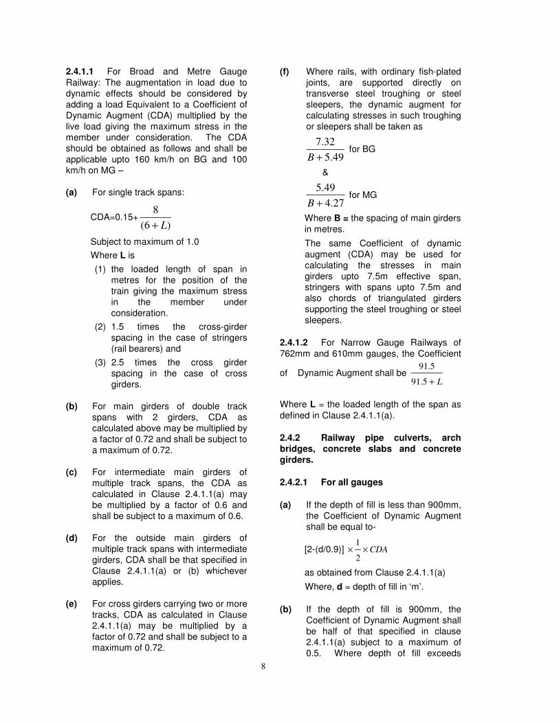
2.4.1.1 For Broad and Metre Gauge
Railway: The augmentation in load due to
dynamic effects should be considered by
adding a load Equivalent to a Coefficient of
Dynamic Augment (CDA) multiplied by the
live load giving the maximum stress in the
member under consideration. The CDA
should be obtained as follows and shall be
applicable upto 160 km/h on BG and 100
km/h on MG –
(a) For single track spans:
CDA=0.15+)6(
8
L+
Subject to maximum of 1.0
Where L is
(1) the loaded length of span in
metres for the position of the
train giving the maximum stress
in the member under
consideration.
(2) 1.5 times the cross-girder
spacing in the case of stringers
(rail bearers) and
(3) 2.5 times the cross girder
spacing in the case of cross
girders.
(b) For main girders of double track
spans with 2 girders, CDA as
calculated above may be multiplied by
a factor of 0.72 and shall be subject to
a maximum of 0.72.
(c) For intermediate main girders of
multiple track spans, the CDA as
calculated in Clause 2.4.1.1(a) may
be multiplied by a factor of 0.6 and
shall be subject to a maximum of 0.6.
(d) For the outside main girders of
multiple track spans with intermediate
girders, CDA shall be that specified in
Clause 2.4.1.1(a) or (b) whichever
applies.
(e) For cross girders carrying two or more
tracks, CDA as calculated in Clause
2.4.1.1(a) may be multiplied by a
factor of 0.72 and shall be subject to a
maximum of 0.72.
(f) Where rails, with ordinary fish-plated
joints, are supported directly on
transverse steel troughing or steel
sleepers, the dynamic augment for
calculating stresses in such troughing
or sleepers shall be taken as
49.5
32.7
+B for BG
&
27.4
49.5
+B for MG
Where B = the spacing of main girders
in metres.
The same Coefficient of dynamic
augment (CDA) may be used for
calculating the stresses in main
girders upto 7.5m effective span,
stringers with spans upto 7.5m and
also chords of triangulated girders
supporting the steel troughing or steel
sleepers.
2.4.1.2 For Narrow Gauge Railways of
762mm and 610mm gauges, the Coefficient
of Dynamic Augment shall be L+5.91
5.91
Where L = the loaded length of the span as
defined in Clause 2.4.1.1(a).
2.4.2 Railway pipe culverts, arch
bridges, concrete slabs and concrete
girders.
2.4.2.1 For all gauges
(a) If the depth of fill is less than 900mm,
the Coefficient of Dynamic Augment
shall be equal to-
[2-(d/0.9)] CDA××2
1
as obtained from Clause 2.4.1.1(a)
Where, d = depth of fill in ‘m’.
(b) If the depth of fill is 900mm, the
Coefficient of Dynamic Augment shall
be half of that specified in clause
2.4.1.1(a) subject to a maximum of
0.5. Where depth of fill exceeds
9
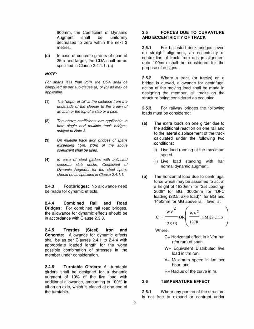
900mm, the Coefficient of Dynamic
Augment shall be uniformly
decreased to zero within the next 3
metres.
(c) In case of concrete girders of span of
25m and larger, the CDA shall be as
specified in Clause 2.4.1.1. (a)
NOTE:
For spans less than 25m, the CDA shall be
computed as per sub-clause (a) or (b) as may be
applicable.
(1) The “depth of fill” is the distance from the
underside of the sleeper to the crown of
an arch or the top of a slab or a pipe.
(2) The above coefficients are applicable to
both single and multiple track bridges,
subject to Note 3.
(3) On multiple track arch bridges of spans
exceeding 15m, 2/3rd of the above
coefficient shall be used.
(4) In case of steel girders with ballasted
concrete slab decks, Coefficient of
Dynamic Augment for the steel spans
should be as specified in Clause 2.4.1.1.
2.4.3 Footbridges: No allowance need
be made for dynamic effects.
2.4.4 Combined Rail and Road
Bridges: For combined rail road bridges,
the allowance for dynamic effects should be
in accordance with Clause 2.3.3.
2.4.5 Trestles (Steel), Iron and
Concrete: Allowance for dynamic effects
shall be as per Clauses 2.4.1 to 2.4.4 with
appropriate loaded length for the worst
possible combination of stresses in the
member under consideration.
2.4.6 Turntable Girders: All turntable
girders shall be designed for a dynamic
augment of 10% of the live load with
additional allowance, amounting to 100% in
all on an axle, which is placed at one end of
the turntable.
2.5 FORCES DUE TO CURVATURE
AND ECCENTRICITY OF TRACK
2.5.1 For ballasted deck bridges, even
on straight alignment, an eccentricity of
centre line of track from design alignment
upto 100mm shall be considered for the
purpose of designs.
2.5.2 Where a track (or tracks) on a
bridge is curved, allowance for centrifugal
action of the moving load shall be made in
designing the member, all tracks on the
structure being considered as occupied.
2.5.3 For railway bridges the following
loads must be considered:
(a) The extra loads on one girder due to
the additional reaction on one rail and
to the lateral displacement of the track
calculated under the following two
conditions:
(i) Live load running at the maximum
speed.
(ii) Live load standing with half
normal dynamic augment.
(b) The horizontal load due to centrifugal
force which may be assumed to act at
a height of 1830mm for “25t Loading-
2008” for BG, 3000mm for “DFC
loading (32.5t axle load)” for BG and
1450mm for MG above rail level is:
= UnitsMKSin
127R
2WV
OR
12.95R
2WV
C
Where,
C= Horizontal effect in kN/m run
(t/m run) of span.
W= Equivalent Distributed live
load in t/m run.
V= Maximum speed in km per
hour, and
R= Radius of the curve in m.
2.6 TEMPERATURE EFFECT
2.6.1 Where any portion of the structure
is not free to expand or contract under
10
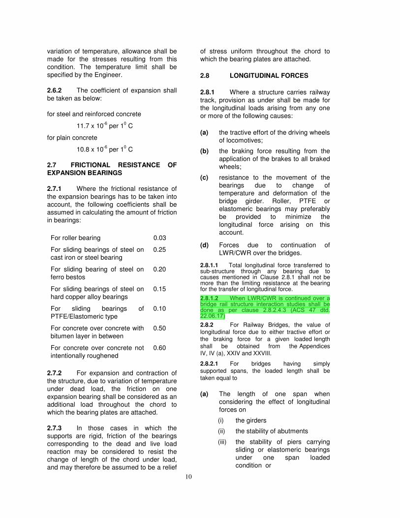
variation of temperature, allowance shall be
made for the stresses resulting from this
condition. The temperature limit shall be
specified by the Engineer.
2.6.2 The coefficient of expansion shall
be taken as below:
for steel and reinforced concrete
11.7 x 10⁻⁶
per 10 C
for plain concrete
10.8 x 10⁻⁶
per 10 C
2.7 FRICTIONAL RESISTANCE OF
EXPANSION BEARINGS
2.7.1 Where the frictional resistance of
the expansion bearings has to be taken into
account, the following coefficients shall be
assumed in calculating the amount of friction
in bearings:
For roller bearing 0.03
For sliding bearings of steel on
cast iron or steel bearing
0.25
For sliding bearing of steel on
ferro bestos
0.20
For sliding bearings of steel on
hard copper alloy bearings
0.15
For sliding bearings of
PTFE/Elastomeric type
0.10
For concrete over concrete with
bitumen layer in between
0.50
For concrete over concrete not
intentionally roughened
0.60
2.7.2 For expansion and contraction of
the structure, due to variation of temperature
under dead load, the friction on one
expansion bearing shall be considered as an
additional load throughout the chord to
which the bearing plates are attached.
2.7.3 In those cases in which the
supports are rigid, friction of the bearings
corresponding to the dead and live load
reaction may be considered to resist the
change of length of the chord under load,
and may therefore be assumed to be a relief
of stress uniform throughout the chord to
which the bearing plates are attached.
2.8 LONGITUDINAL FORCES
2.8.1 Where a structure carries railway
track, provision as under shall be made for
the longitudinal loads arising from any one
or more of the following causes:
(a) the tractive effort of the driving wheels
of locomotives;
(b) the braking force resulting from the
application of the brakes to all braked
wheels;
(c) resistance to the movement of the
bearings due to change of
temperature and deformation of the
bridge girder. Roller, PTFE or
elastomeric bearings may preferably
be provided to minimize the
longitudinal force arising on this
account.
(d) Forces due to continuation of
LWR/CWR over the bridges.
2.8.1.1 Total longitudinal force transferred to sub-structure through any bearing due to causes mentioned in Clause 2.8.1 shall not be more than the limiting resistance at the bearing for the transfer of longitudinal force.
2.8.1.2 When LWR/CWR is continued over a bridge rail structure interaction studies shall be done as per clause 2.8.2.4.3 (ACS 47 dtd. 22.06.17)2.8.2 For Railway Bridges, the value of
longitudinal force due to either tractive effort or
the braking force for a given loaded length
shall be obtained from the Appendices
IV, IV (a), XXIV and XXVIII.
2.8.2.1 For bridges having simply
supported spans, the loaded length shall be
taken equal to
(a) The length of one span when
considering the effect of longitudinal
forces on
(i) the girders
(ii) the stability of abutments
(iii) the stability of piers carrying
sliding or elastomeric bearings
under one span loaded
condition or
11
(iv) the stability of piers carrying
one fixed and one free (roller or
PTFE) bearings.
(b) The length of two spans when
considering stability of piers carrying
fixed or sliding or elastomeric
bearings, under the two span loaded
conditions. The total longitudinal
force shall be considered divided
between the two spans in proportion
to their lengths.
2.8.2.1.1 In case of continuous span
bridges, appropriate loaded length shall be
considered which will give the worst effect.
2.8.2.2 No increase shall be made in the
longitudinal force for the dynamic effect.
2.8.2.3 The longitudinal forces shall be
considered as acting horizontally through
the knuckle pins in case of bearings having
rocking arrangement or through girder seats
in case of sliding, elastomeric or PTFE
bearings for the design of bearings and sub-
structure.
2.8.2.4.1 For sub-structure having sliding
or elastomeric bearings, following
percentage of net longitudinal force from the
loaded spans after allowing for dispersion as
per Clauses 2.8.3.1, 2.8.3.2 and 2.8.3.3
shall be considered for the design:
Abutment 50%
Pier 40%
In case of multi-span bridges, the design of
sub-structure shall also be checked for 20%
of net longitudinal force transferred from the
span adjoining to the spans directly
supported by the sub-structure under
consideration and considering the directly
supported spans as unloaded. However,
this force shall not be more than the limiting
resistance of the bearings on the sub-
structure for the transfer of longitudinal force
under unloaded condition.
2.8.2.4.2 For spans having roller or
PTFE bearings at one end, the whole of the
net longitudinal force after allowing for
dispersion as per Clauses 2.8.3.1, 2.8.3.2 and
2.8.3.3 shall be considered to act through
the fixed end.
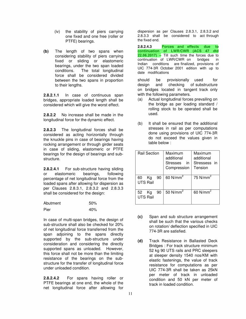
2.8.2.4.3 Forces and effects due tocontinuation of LWR/CWR (ACS 47 dtd 22.06.2017) – Till such time the forces due tocontinuation of LWR/CWR on bridges in
Indian conditions are finalized, provisions of
UIC 774-3R October 2001 edition with up to
date modifications
should be provisionally used for
design and checking of substructure
on bridges located in tangent track only
with the following parameters.
(a) Actual longitudinal forces prevailing on
the bridge as per loading standard /
rolling stock to be operated shall be
used.
(b) It shall be ensured that the additional
stresses in rail as per computations
done using provisions of UIC 774-3R
do not exceed the values given in
table below :
(c) Span and sub structure arrangement
shall be such that the various checks
on rotation/ deflection specified in UIC
774-3R are satisfied.
(d) Track Resistance in Ballasted Deck
Bridges : For track structure minimum
52 kg 90 UTS rails and PRC sleepers
at sleeper density 1540 nos/KM with
elastic fastenings, the value of track
resistance for computations as per
UIC 774-3R shall be taken as 25kN
per meter of track in unloaded
condition and 50 kN per meter of
track in loaded condition.
Rail Section Maximum
additional
Stresses in
Compression
Maximum
additional
Stressess in
Tension
60 Kg 90
UTS Rail
60 N/mm2
75 N/mm2
52 Kg 90
UTS Rail
50 N/mm2
60 N/mm2
12
(e) The computations can be done either
using graphs or simplified approach
or computer program as indicated in
UIC 774-3R provided the conditions
specified for their adoption are
satisfied the computer program shall
be validated with methodology given
in UIC-774-3R before use.
(f) Ballasted deck bridges without
bearings (slabs, box culverts and
arches) need not be checked for
forces/effects due to continuation of
LWR/CWR.
(g) If rail-free fastenings are provided as
per provisions of Manual Of
Instructions On Long Welded Rails,
such that there is no interaction
between the rail and the bridge, then
there is no need for checking for
forces/effects due to continuation of
LWR/CWR.
2.8.2.4.4. In case the stipulations given in
para 2.8.2.4.3 above are not fulfilled,
measures such as provision of suitable
expansion joint or non-provision of
LWR/CWR on that particular bridge shall be
adopted as decided by Principal Chief
Engineer of the zonal railway.
2.8.3 Dispersion and distribution of
longitudinal forces.
2.8.3.1 In case of bridges having open
deck provided with through welded rails, rail-
free fastenings and adequate anchorage of
welded rails on approaches (by providing
adequate density of sleepers, ballast
cushion and its consolidation etc., but
without any switch expansion joints) the
dispersion of longitudinal force through
track, away from the loaded length, may be
allowed to the extent of 25% of the
magnitude of longitudinal force and subject
to a minimum of 16t for BG and 12t for MMG
or MGML and 10t for MGBL. This shall also
apply to bridges having open deck with
jointed track with rail-free fastenings or
ballasted deck, however without any switch
expansion or mitred joints in either case.
Where suitably designed elastomeric
bearings are provided the aforesaid
dispersion may be increased to 35% of the
magnitude of longitudinal force.
NOTE: Length of approach for the above
purpose shall be taken as minimum
30m.
2.8.3.2 The dispersion of longitudinal
force indicated in Clause 2.8.3.1 shall not
exceed the capacity of track for dispersing
the longitudinal force to the approaches nor
shall it exceed the capacity of anchored
length of the track on the approaches to
resist dispersed longitudinal force. This
aspect may be given special attention for the
stability of track in case of multi-span
bridges provided with elastomeric bearings
on all spans.
2.8.3.3 In case of multi-span bridges
having continuous spans, or flexible
supports such as tall or hollow RCC piers or
steel trestles, or flexible bearings
(elastomeric bearings) on all supports, or
any other special features, which are likely,
to affect the distribution of longitudinal forces
significantly, the dispersion and distribution
of longitudinal forces shall be determined by
suitable analysis. The analysis shall take
into account stiffness and frictional
characteristics of various resisting elements
viz., supports, bridge girders, bearings, rail-
girder fixtures, track on bridge and
approaches etc.
2.8.3.4 For the design of new bridges and
in case of rebuilding of existing bridges,
dispersion of longitudinal force shall not be
allowed.
2.8.4 When the bridge carries more
than one track. Longitudinal Force (as
specified in paras 2.8.1 to 2.8.3 and 2.8.5)
shall be considered to act simultaneously on
all tracks considered loaded such as to
produce the worst effect on the component
being designed, multiplied by factor given
below.
No. of tracks
Considered loaded
Multiplication Factor
for Longitudinal
Force
13
1 1.00
2 1.00
3 0.90*
4 or more 0.75*
* Note : Multiplication factor applicable only
if the bridge element is common for multiple
lines.
2.8.5 When considering seismic forces,
only 50% of gross tractive effort/braking
force, to be reduced by taking dispersion
and distribution of longitudinal forces, shall
be considered along with horizontal seismic
forces along/across the direction of the
traffic.
2.9 RACKING FORCES
2.9.1 Lateral bracings of the loaded
deck of railway spans shall be designed to
resist, in addition to the wind and centrifugal
loads specified above, a lateral load due to
racking forces of 5.88 kN/m (600 kg/m)
treated as moving load. This lateral load
need not be taken into account when
calculating stresses in chords or flanges of
main girders.
For “DFC loading (32.5t axle load)”, the
lateral load due to racking forces of 13.72
kN/m(1400 kg/m) be treated as moving load.
2.9.2 In the cases of effective spans
upto 20m it is not necessary to calculate
wind stresses but, in railway bridges lateral
bracings shall be provided designed for a
lateral load due to wind and racking forces
of 8.82 kN/m (900 kg/m) treated as a moving
load in addition to the centrifugal load, if any.
In case of “DFC loading (32.5t axle load)”,
lateral load due to wind and racking forces
of 16.66 kN/m(1700 kg/m) be treated as
moving load in addition to the centrifugal
load, if any.
2.10 FORCES ON PARAPETS
Railings or parapets shall have a minimum
height above the adjacent roadway or
footway surface, of 1m less one half the
horizontal width of the top rail or top of the
parapet. They shall be designed to resist a
lateral horizontal force and a vertical force of
1.47 kN/m(150 kg/m) applied simultaneously
at the top of the railing or parapet.
2.11 WIND PRESSURE EFFECT
2.11.1 Basic Wind Pressures
2.11.1.1 Wind pressures are expressed in
terms of a basic wind pressure ‘P’ which is
an equivalent static pressure in the
windward direction.
2.11.1.2 In choosing the appropriate wind
velocity for the purpose of determining the
basic wind pressure, due consideration shall
be given to the degree of exposure
appropriate to the locality and also to the
local meteorological data.
2.11.1.3 For purposes of design where no
meteorological records are available, the
Map as given in IS: 875 (Part 3) in
conjunction with the Table therein, may be
used for determining the basic wind
pressures.
2.11.2 The wind pressure specified
above shall apply to all loaded or unloaded
bridges provided that a bridge shall not be
considered to be carrying any live load when
the wind pressure at deck level exceeds the
following limits:
Broad Gauge
bridges
1.47 kN/m2
(150
kg/m2)
Metre and Narrow
Gauge Bridges
0.98 kN/m2
(100kg/m2)
Foot-bridges 0.74 kN/m2
(75
kg/m2)
2.11.3 Wind Pressure
2.11.3.1 For Railway and Footbridges:
The wind pressure shall be computed from
the appropriate basic wind pressure given in
Clause 2.11.1 and the exposed area as
given below:
(a) For unloaded spans and trestles net
exposed area shall be considered as
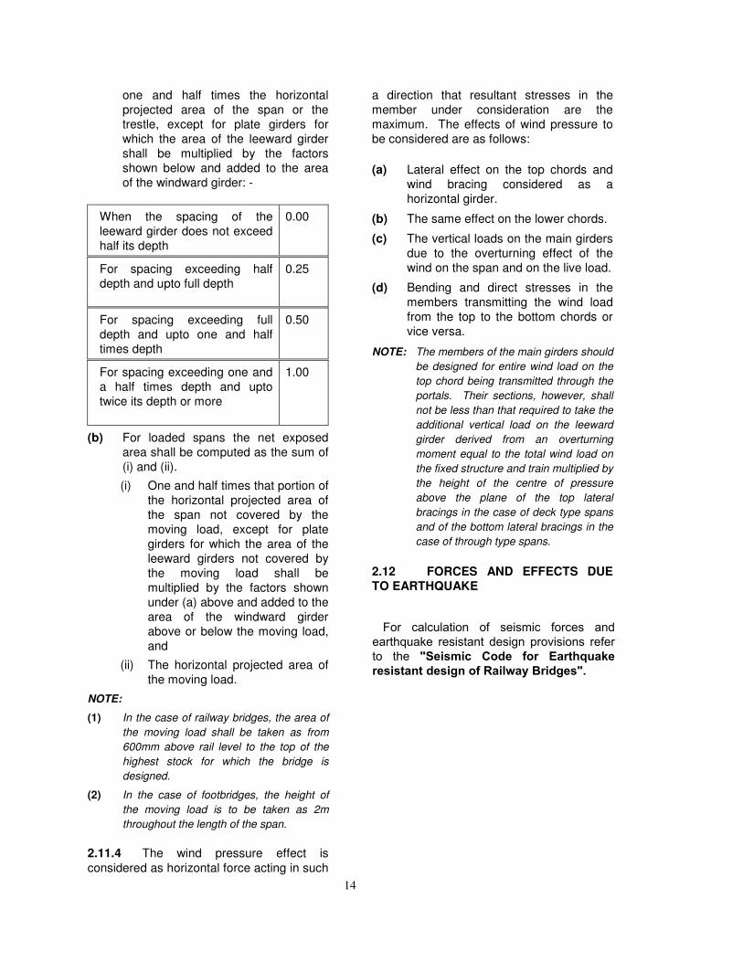
14
one and half times the horizontal
projected area of the span or the
trestle, except for plate girders for
which the area of the leeward girder
shall be multiplied by the factors
shown below and added to the area
of the windward girder: -
When the spacing of the
leeward girder does not exceed
half its depth
0.00
For spacing exceeding half
depth and upto full depth
0.25
For spacing exceeding full
depth and upto one and half
times depth
0.50
For spacing exceeding one and
a half times depth and upto
twice its depth or more
1.00
(b) For loaded spans the net exposed
area shall be computed as the sum of
(i) and (ii).
(i) One and half times that portion of
the horizontal projected area of
the span not covered by the
moving load, except for plate
girders for which the area of the
leeward girders not covered by
the moving load shall be
multiplied by the factors shown
under (a) above and added to the
area of the windward girder
above or below the moving load,
and
(ii) The horizontal projected area of
the moving load.
NOTE:
(1) In the case of railway bridges, the area of
the moving load shall be taken as from
600mm above rail level to the top of the
highest stock for which the bridge is
designed.
(2) In the case of footbridges, the height of
the moving load is to be taken as 2m
throughout the length of the span.
2.11.4 The wind pressure effect is
considered as horizontal force acting in such
a direction that resultant stresses in the
member under consideration are the
maximum. The effects of wind pressure to
be considered are as follows:
(a) Lateral effect on the top chords and
wind bracing considered as a
horizontal girder.
(b) The same effect on the lower chords.
(c) The vertical loads on the main girders
due to the overturning effect of the
wind on the span and on the live load.
(d) Bending and direct stresses in the
members transmitting the wind load
from the top to the bottom chords or
vice versa.
NOTE: The members of the main girders should
be designed for entire wind load on the
top chord being transmitted through the
portals. Their sections, however, shall
not be less than that required to take the
additional vertical load on the leeward
girder derived from an overturning
moment equal to the total wind load on
the fixed structure and train multiplied by
the height of the centre of pressure
above the plane of the top lateral
bracings in the case of deck type spans
and of the bottom lateral bracings in the
case of through type spans.
2.12 FORCES AND EFFECTS DUE
TO EARTHQUAKE
For calculation of seismic forces and earthquake resistant design provisions refer to the "Seismic Code for Earthquake resistant design of Railway Bridges".
15
Para 2.
12.1
to Para
2.12
.12 de
leted
vide
ACS 49
of B
ridge
Rule
dtd 2
6.12.2
017
16
Para 2.12.1 to Para 2.12.12 deleted
vide A
CS 49 of Brid
ge Rule d
td 26.12.2017
17
Para 2.
12.1
to Para
2.12
.12 de
leted
vide
ACS 49
of B
ridge
Rule
dtd 2
6.12.2
017
18
Para 2.12.1 to Para 2.12.12 deleted
vide A
CS 49 of Brid
ge Rule d
td 26.12.2017
19
2.13 ERECTION FORCES AND
EFFECTS
2.13.1 The weight of all permanent and
temporary material together with all other
forces and effects which can operate on any
part of the structure during erection shall be
taken into account.
2.13.2 Allowance shall be made in the
design for stresses set up in any member
during erection; such stresses may be
different from those, which the member will
be subjected to during actual working.
2.14 DERAILMENT LOADS
2.14.1 Derailment loads for “25t
Loading-2008” for BG shall be considered
for ballasted deck bridges as per Appendix-
XXV.
2.14.2 Derailment loads for DFC loading
(32.5t axle load) shall be considered for
ballasted deck bridges as per Appendix-
XXIX.
2.14.3 The loads specified in Clauses
2.14.1 and 2.14.2 shall be applied at the top
surface of ballast and may be assumed to
disperse at a slope of half horizontal to one
vertical.
2.15 LOAD DUE TO PLASSER’S
QUICK RELAY SYSTEM (PQRS)
2.15.1 Load due to working of Plasser’s
Quick Relay System for BG shall be
considered for reduced Coefficient of
Dynamic Augment for maximum speed of 20
kmph as per Appendix X for the most
unfavourable position. The load due to
auxiliary track shall be considered
separately.
2.15.2 The dispersion of load, as
specified in Clause 2.15.1, shall be as per
Clause 2.3.4.2.
2.16 Forces due to accidental impact from any vehicles such as road vehicles, ships or derailed train vehicles using the bridge
(ACS 48 dtd. 22.06.17) Remaining data of ACS 48 is enclosed with this document as Annexure A
3.0 RULES FOR ASSESSING THE
STRENGTH OF EXISTING RAILWAY BRIDGES
3.1 The preceding rules shall apply to the
investigation of the strength of existing bridges
except in so far as they are modified in clauses
3.2 to 3.6.
3.2 When it is proposed to increase
sanctioned speeds, to remove marshalling
restrictions, or to run any different type of
stock involving increased loading on an
Para 2
.12.1
to P
ara 2
.12.12
delet
ed vi
de A
CS 49 of
Bridge
Rule
dtd
26.12
.2017
20
existing bridge over that already sanctioned,
the Engineer shall be responsible for
obtaining fresh sanction from the
Commissioner of Railway Safety. The
Engineer shall certify that such usage will
not involve danger to the travelling public.
3.3 Where no rail joint occurs on a
span and within 10m on its approaches, the
Coefficient of Dynamic Augment (CDA) as
calculated in para 2.4.1 and 2.4.2 may be
diminished by an amount equal to
0.75/(span in m), subject to a maximum
reduction of 20% of the calculated value of
CDA for spans of 7.5m and less.
3.3.1 Provided they are certified by the
Engineer as being in sound condition and of
satisfactory design, and further that the
maximum permissible speed will, in no
circumstances be exceeded, the Coefficient
of Dynamic Augment shall be adopted as
below:
(a) CDA laid down in Clauses 2.4.1 and
2.4.2 (diminished) according to
Clauses 3.3 where applicable may
be multiplied by the factor (Vr/V)
where Vr is the permissible speed
and V is-
(i) 125 km/h for trains hauled by
diesel and electrical locomotives
and 80 km/h for steam
locomotives on BG.
(ii) 100 km/h for trains hauled by
diesel and electric locomotives
and 60 km/h for steam
locomotives on MG.
NOTE: Bridges found fit for 125 km/h on BG
may be cleared for speeds upto 160
km/h for passenger services with stock
specially cleared to run at such speeds.
3.3.2 The Coefficient of Dynamic
Augment shall in no case be taken as less
than 0.1.
3.3.3 In cases, where the Coefficient of
Dynamic Augment is reduced on the basis
of a maximum speed, the transportation
branch are to be held responsible that the
restriction is rigidly observed. It must also
be certified by the responsible authority that
the condition of the bridge and of the
permanent way warrants this relaxation of
Coefficient of Dynamic Augment, which has
the effect of increasing the working stresses.
3.4 For the purpose of calculating the
longitudinal forces and its dispersion and
distribution in case of existing bridges,
clause 2.8 shall apply generally. For trains
hauled by steam locomotives, the maximum
tractive force may be assumed to be 25% of
the axle load of the coupled wheels on
actual engines under consideration and the
maximum braking force to be 20% of the
actual braked engine axle loads plus 10% of
the other braked axle loads. For trains
hauled by diesel or AC or DC locomotives,
the maximum tractive force shall be as
specified for the locomotive distributed
equally amongst the driving axles. The
braking force for such locomotives shall be
as specified for them distributed equally
amongst the braked axles, together with
10% of the weight of the braked trailing
axles covering the loaded length, if fitted
with vacuum brakes. For trailing axles fitted
with air brakes, braking force shall be as
specified for them distributed equally
amongst the braked axles covering the
loaded length, subject to a maximum of
13.4% of the weight of the braked axles.
3.5 For checking adequacy of existing
bridges for permitting rolling stock involving
higher loads, the bridge shall not be
considered to be carrying any live load when
the wind pressure at deck level exceeds 100
kg/m2 (0.98kN/m
2).
3.6 For checking the adequacy of Existing
Bridges for higher Bridge Loading
Standards/higher axle loads, the Bending
Moments and shear Forces shall be
calculated on the basis of EUDLs specified
for different Loading Standards. In case it is
found inadequate, calculation shall be done
on the basis of actual train axle loads with
the help of software "Moving Load" issued
by RDSO.
4.0 CRITICAL SPEED
4.1 Critical speed is defined as the
speed at which the external forcing
21
frequency will be equal to one of the natural
frequencies of the track-bridge-vehicle
system, contributing to vertical response of
the bridge.
4.2 Critical speed in the case of steam
locomotives and for open web girders only
may be calculated by any of the following
methods:
(i) by running trains at varying
speeds across the bridge and
determining the speed giving the
maximum deflection.
(ii) by ascertaining the maximum
static deflection under live load
and applying the following
formula:
)P
PWd(
2CV
+=
Where-
V = critical speed in km/h
C = circumference of driving
wheels in m.
W = dead load of the span in kN
(t) per m
P = equivalent live load in kN
(t) per m run of the train on
the span, at the position
giving maximum Bending
Moment, and
d = maximum static deflection
in m caused by the live
load; and
(iii) by the following approximate
formula: - L
V266
=
Where,
V = critical speed km/h and
L = effective length of span in
m.
4.3 Speed restrictions for open web
girders for steam traction in the range of
critical speed ± 10 km/h as determined in
Clause 4.2 should be avoided.
5.0 Details of old standard loadings for Bridges: -
For Broad Gauge (1676mm), the existing loads are given in table below for Broad Gauge Standard Loading (BGML & BGBL) of 1926, RBG loading of 1975, MBG Loading of 1987 and HM loading of 2000.
(a) Broad Gauge Standard Loading(BGML & BGBL) of 1926: -
- The BGML & BGBL Loadings are of-1926
- The details of loading diagrams,EUDL for BM & Shear Force &Tractive Effort & Braking Force, aregiven in the appendix given asbelow: -
Loading diagrams for Broad Gauge Standard Loadings (BGML and BGBL)-1926.
Appendix-VI
EUDL in tonnes on each track and CDA values for Broad Gauge Standard Loadings (BGML and BGBL)-1926.
Appendix-VII
Longitudinal loads in tonnes (without deduction for dispersion) for Broad Gauge Standard Loadings (BGML and BGBL)-1926.
Appendix-VIII
(b) Revised Broad Gauge Loading of-1975: -
- The RBG Loading is of-1975
- The details of loading diagrams,EUDL for BM & Shear Force &Tractive Effort & Braking Forceare given in the appendix givenas below:
Loading diagrams for Revised Broad Gauge Standard Loading (RBG)-1975.
Appendix-XI
EUDL in tonnes on each track and CDA values for Revised Broad Gauge Standard Loadings (RBG)-1975.
Appendix-XII
Longitudinal loads in tonnes (without deduction of dispersion) for revised Broad Gauge Standard Loading (RBG)-1975
Appendix-XIII
22
(c ) Modified Broad Gauge Loading of-1987:
- The MBG Loading is of-1987.
- The details of loading diagrams,EUDL for BM & Shear Force &Tractive Effort & Braking Forceare given in the appendix givenas below: -
Loading diagrams for MBG-1987 loading.
Appendix-XIX
EUDL in tonnes on each track and CDA values for MBG-1987 loading.
Appendix-XX & XX(a)
Longitudinal loads in tonnes (without deduction of dispersion) for MBG-1987 loading.
Appendix-XXI
- Details of Derailment loads forballasted deck bridges for MBGloading are given in Appendix-IX
(d) HM Loading: -
- The HM Loading is of-2000.
- The details of loading diagrams,EUDL for BM & Shear Force &Tractive Effort & Braking Forceare given in the appendix givenas below: -
- Details of Derailment loads for ballasted deck bridges for HM loading are given in Appendix-XVII.
Loading diagrams for HM loading.
Appendix-XIV
EUDL in tonnes on each track and CDA values for HM loading.
Appendix-XV & XV(a)
Longitudinal loads in tonnes (without deduction of dispersion) for HM loading.
Appendix-XVI
23
AP
PE
ND
IX I
SH
EE
T 1
OF
3
24
AP
PE
ND
IX I
SH
EE
T 2
OF
3
25
AP
PE
ND
IX I
SH
EE
T 3
OF
3
26
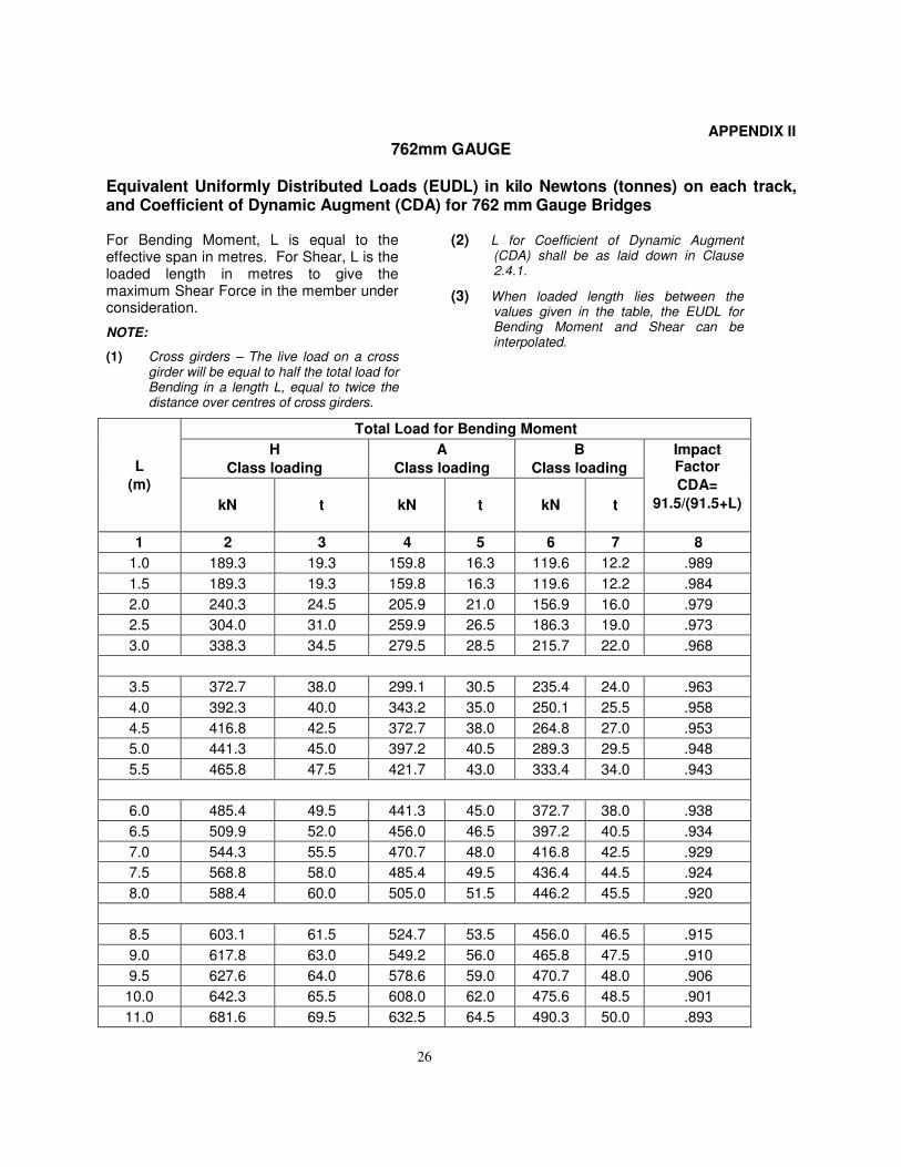
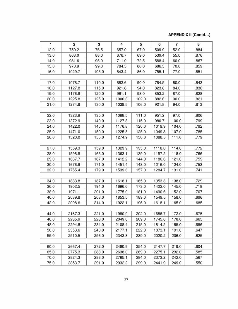
APPENDIX II
762mm GAUGE
Equivalent Uniformly Distributed Loads (EUDL) in kilo Newtons (tonnes) on each track, and Coefficient of Dynamic Augment (CDA) for 762 mm Gauge Bridges For Bending Moment, L is equal to the effective span in metres. For Shear, L is the loaded length in metres to give the maximum Shear Force in the member under consideration.
NOTE:
(1) Cross girders – The live load on a cross girder will be equal to half the total load for Bending in a length L, equal to twice the distance over centres of cross girders.
(2) L for Coefficient of Dynamic Augment (CDA) shall be as laid down in Clause 2.4.1.
(3) When loaded length lies between the values given in the table, the EUDL for Bending Moment and Shear can be interpolated.
L
(m)
Total Load for Bending Moment
H
Class loading
A
Class loading
B
Class loading
Impact Factor
CDA=
91.5/(91.5+L)
kN t kN t kN t
1 2 3 4 5 6 7 8
1.0 189.3 19.3 159.8 16.3 119.6 12.2 .989
1.5 189.3 19.3 159.8 16.3 119.6 12.2 .984
2.0 240.3 24.5 205.9 21.0 156.9 16.0 .979
2.5 304.0 31.0 259.9 26.5 186.3 19.0 .973
3.0 338.3 34.5 279.5 28.5 215.7 22.0 .968
3.5 372.7 38.0 299.1 30.5 235.4 24.0 .963
4.0 392.3 40.0 343.2 35.0 250.1 25.5 .958
4.5 416.8 42.5 372.7 38.0 264.8 27.0 .953
5.0 441.3 45.0 397.2 40.5 289.3 29.5 .948
5.5 465.8 47.5 421.7 43.0 333.4 34.0 .943
6.0 485.4 49.5 441.3 45.0 372.7 38.0 .938
6.5 509.9 52.0 456.0 46.5 397.2 40.5 .934
7.0 544.3 55.5 470.7 48.0 416.8 42.5 .929
7.5 568.8 58.0 485.4 49.5 436.4 44.5 .924
8.0 588.4 60.0 505.0 51.5 446.2 45.5 .920
8.5 603.1 61.5 524.7 53.5 456.0 46.5 .915
9.0 617.8 63.0 549.2 56.0 465.8 47.5 .910
9.5 627.6 64.0 578.6 59.0 470.7 48.0 .906
10.0 642.3 65.5 608.0 62.0 475.6 48.5 .901
11.0 681.6 69.5 632.5 64.5 490.3 50.0 .893
27
APPENDIX II (Contd…)
1 2 3 4 5 6 7 8
12.0 750.2 76.5 657.0 67.0 509.9 52.0 .884
13.0 863.0 88.0 676.7 69.0 539.4 55.0 .876
14.0 931.6 95.0 711.0 72.5 588.4 60.0 .867
15.0 970.9 99.0 784.5 80.0 686.5 70.0 .859
16.0 1029.7 105.0 843.4 86.0 755.1 77.0 .851
17.0 1078.7 110.0 882.6 90.0 784.5 80.0 .843
18.0 1127.8 115.0 921.8 94.0 823.8 84.0 .836
19.0 1176.8 120.0 961.1 98.0 853.2 87.0 .828
20.0 1225.8 125.0 1000.3 102.0 882.6 90.0 .821
21.0 1274.9 130.0 1039.5 106.0 921.8 94.0 .813
22.0 1323.9 135.0 1088.5 111.0 951.2 97.0 .806
23.0 1372.9 140.0 1127.8 115.0 980.7 100.0 .799
24.0 1422.0 145.0 1176.8 120.0 1019.9 104.0 .792
25.0 1471.0 150.0 1225.8 125.0 1049.3 107.0 .785
26.0 1520.0 155.0 1274.9 130.0 1088.5 111.0 .779
27.0 1559.3 159.0 1323.9 135.0 1118.0 114.0 .772
28.0 1598.5 163.0 1363.1 139.0 1157.2 118.0 .766
29.0 1637.7 167.0 1412.2 144.0 1186.6 121.0 .759
30.0 1676.9 171.0 1451.4 148.0 1216.0 124.0 .753
32.0 1755.4 179.0 1539.6 157.0 1284.7 131.0 .741
34.0 1833.8 187.0 1618.1 165.0 1353.3 138.0 .729
36.0 1902.5 194.0 1696.6 173.0 1422.0 145.0 .718
38.0 1971.1 201.0 1775.0 181.0 1490.6 152.0 .707
40.0 2039.8 208.0 1853.5 189.0 1549.5 158.0 .696
42.0 2098.6 214.0 1922.1 196.0 1618.1 165.0 .685
44.0 2167.3 221.0 1980.9 202.0 1686.7 172.0 .675
46.0 2235.9 228.0 2049.6 209.0 1745.6 178.0 .665
48.0 2294.8 234.0 2108.4 215.0 1814.2 185.0 .656
50.0 2353.6 240.0 2177.1 222.0 1873.1 191.0 .647
55.0 2510.5 256.0 2343.8 239.0 2020.2 206.0 .625
60.0 2667.4 272.0 2490.9 254.0 2147.7 219.0 .604
65.0 2775.3 283.0 2638.0 269.0 2275.1 232.0 .585
70.0 2824.3 288.0 2785.1 284.0 2373.2 242.0 .567
75.0 2853.7 291.0 2932.2 299.0 2441.9 249.0 .550
28
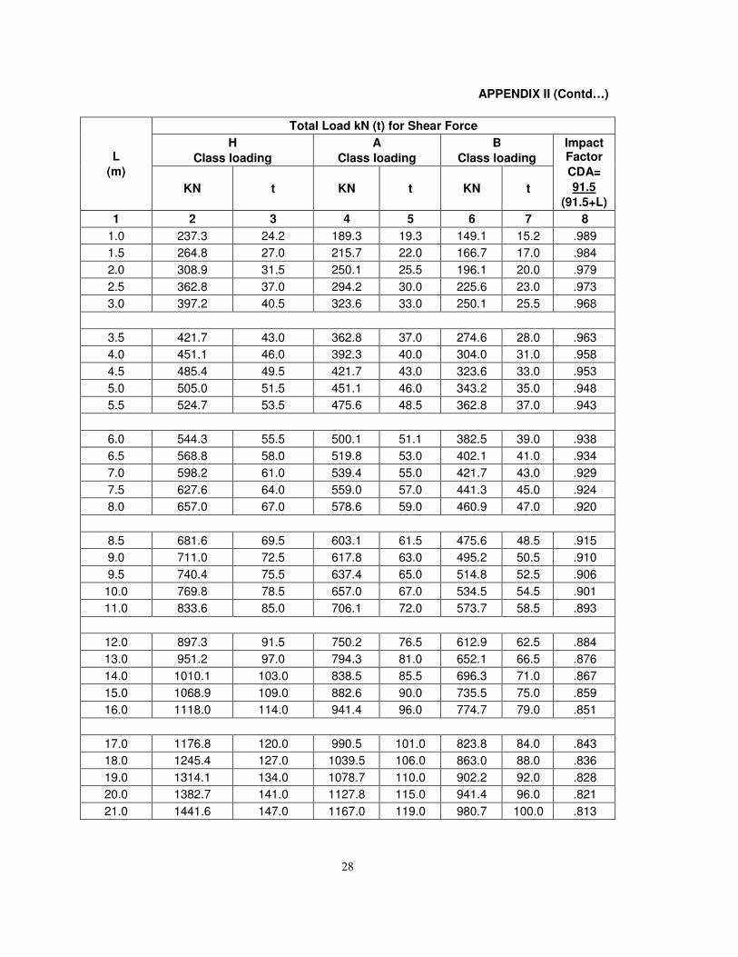
APPENDIX II (Contd…)
L
(m)
Total Load kN (t) for Shear Force
H
Class loading
A
Class loading
B
Class loading
Impact Factor
CDA=
91.5
(91.5+L) KN t KN t KN t
1 2 3 4 5 6 7 8
1.0 237.3 24.2 189.3 19.3 149.1 15.2 .989
1.5 264.8 27.0 215.7 22.0 166.7 17.0 .984
2.0 308.9 31.5 250.1 25.5 196.1 20.0 .979
2.5 362.8 37.0 294.2 30.0 225.6 23.0 .973
3.0 397.2 40.5 323.6 33.0 250.1 25.5 .968
3.5 421.7 43.0 362.8 37.0 274.6 28.0 .963
4.0 451.1 46.0 392.3 40.0 304.0 31.0 .958
4.5 485.4 49.5 421.7 43.0 323.6 33.0 .953
5.0 505.0 51.5 451.1 46.0 343.2 35.0 .948
5.5 524.7 53.5 475.6 48.5 362.8 37.0 .943
6.0 544.3 55.5 500.1 51.1 382.5 39.0 .938
6.5 568.8 58.0 519.8 53.0 402.1 41.0 .934
7.0 598.2 61.0 539.4 55.0 421.7 43.0 .929
7.5 627.6 64.0 559.0 57.0 441.3 45.0 .924
8.0 657.0 67.0 578.6 59.0 460.9 47.0 .920
8.5 681.6 69.5 603.1 61.5 475.6 48.5 .915
9.0 711.0 72.5 617.8 63.0 495.2 50.5 .910
9.5 740.4 75.5 637.4 65.0 514.8 52.5 .906
10.0 769.8 78.5 657.0 67.0 534.5 54.5 .901
11.0 833.6 85.0 706.1 72.0 573.7 58.5 .893
12.0 897.3 91.5 750.2 76.5 612.9 62.5 .884
13.0 951.2 97.0 794.3 81.0 652.1 66.5 .876
14.0 1010.1 103.0 838.5 85.5 696.3 71.0 .867
15.0 1068.9 109.0 882.6 90.0 735.5 75.0 .859
16.0 1118.0 114.0 941.4 96.0 774.7 79.0 .851
17.0 1176.8 120.0 990.5 101.0 823.8 84.0 .843
18.0 1245.4 127.0 1039.5 106.0 863.0 88.0 .836
19.0 1314.1 134.0 1078.7 110.0 902.2 92.0 .828
20.0 1382.7 141.0 1127.8 115.0 941.4 96.0 .821
21.0 1441.6 147.0 1167.0 119.0 980.7 100.0 .813
29
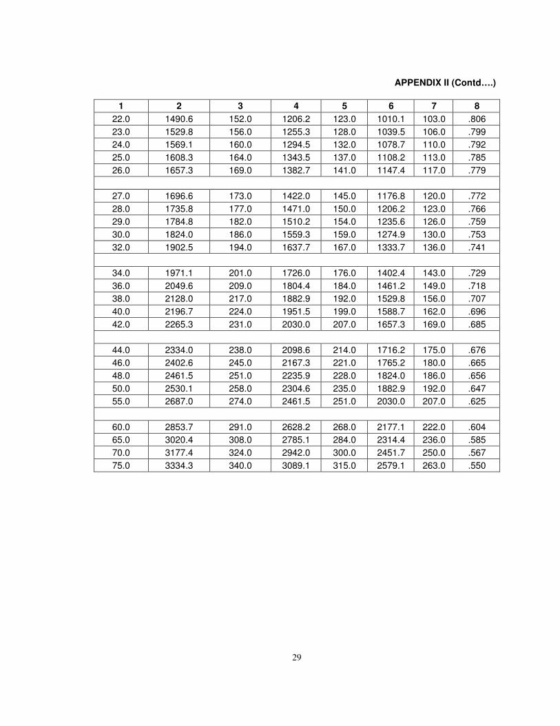
APPENDIX II (Contd….)
1 2 3 4 5 6 7 8
22.0 1490.6 152.0 1206.2 123.0 1010.1 103.0 .806
23.0 1529.8 156.0 1255.3 128.0 1039.5 106.0 .799
24.0 1569.1 160.0 1294.5 132.0 1078.7 110.0 .792
25.0 1608.3 164.0 1343.5 137.0 1108.2 113.0 .785
26.0 1657.3 169.0 1382.7 141.0 1147.4 117.0 .779
27.0 1696.6 173.0 1422.0 145.0 1176.8 120.0 .772
28.0 1735.8 177.0 1471.0 150.0 1206.2 123.0 .766
29.0 1784.8 182.0 1510.2 154.0 1235.6 126.0 .759
30.0 1824.0 186.0 1559.3 159.0 1274.9 130.0 .753
32.0 1902.5 194.0 1637.7 167.0 1333.7 136.0 .741
34.0 1971.1 201.0 1726.0 176.0 1402.4 143.0 .729
36.0 2049.6 209.0 1804.4 184.0 1461.2 149.0 .718
38.0 2128.0 217.0 1882.9 192.0 1529.8 156.0 .707
40.0 2196.7 224.0 1951.5 199.0 1588.7 162.0 .696
42.0 2265.3 231.0 2030.0 207.0 1657.3 169.0 .685
44.0 2334.0 238.0 2098.6 214.0 1716.2 175.0 .676
46.0 2402.6 245.0 2167.3 221.0 1765.2 180.0 .665
48.0 2461.5 251.0 2235.9 228.0 1824.0 186.0 .656
50.0 2530.1 258.0 2304.6 235.0 1882.9 192.0 .647
55.0 2687.0 274.0 2461.5 251.0 2030.0 207.0 .625
60.0 2853.7 291.0 2628.2 268.0 2177.1 222.0 .604
65.0 3020.4 308.0 2785.1 284.0 2314.4 236.0 .585
70.0 3177.4 324.0 2942.0 300.0 2451.7 250.0 .567
75.0 3334.3 340.0 3089.1 315.0 2579.1 263.0 .550
30
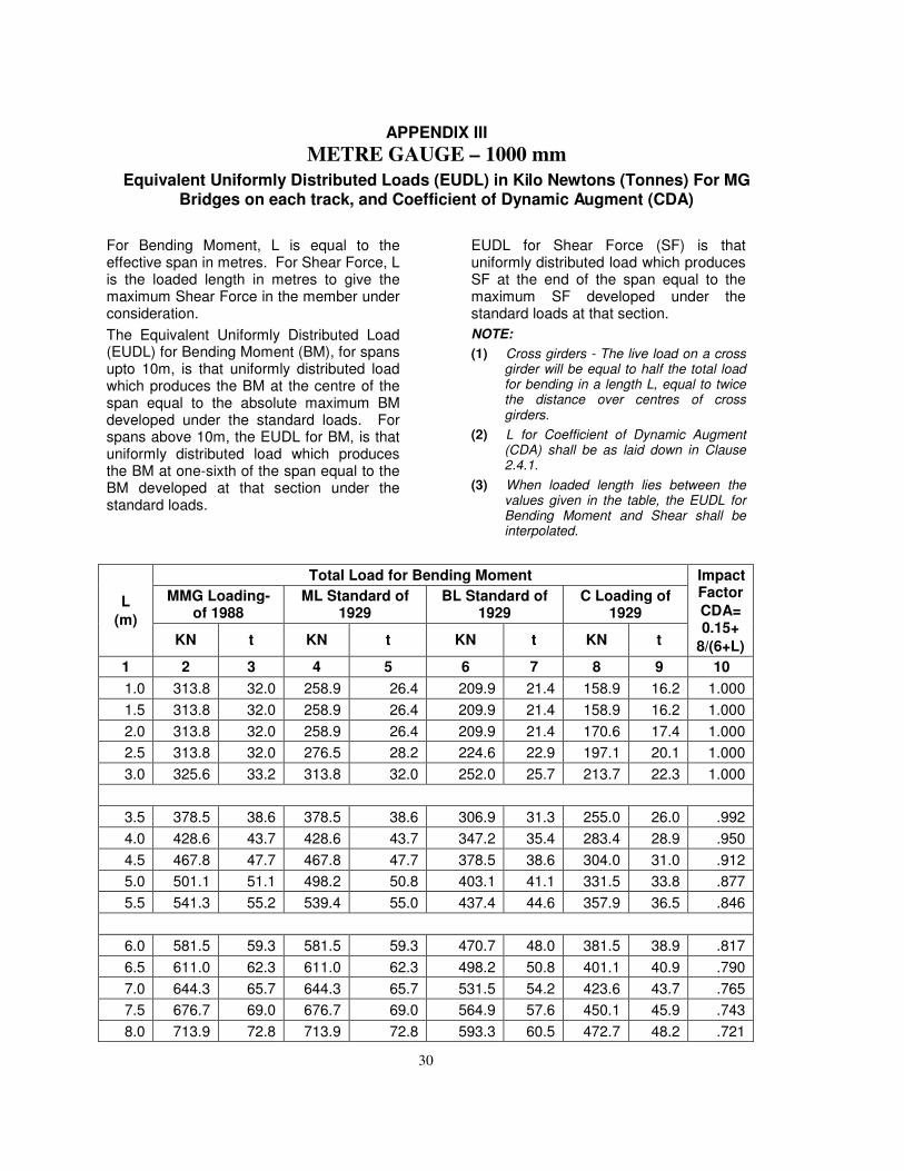
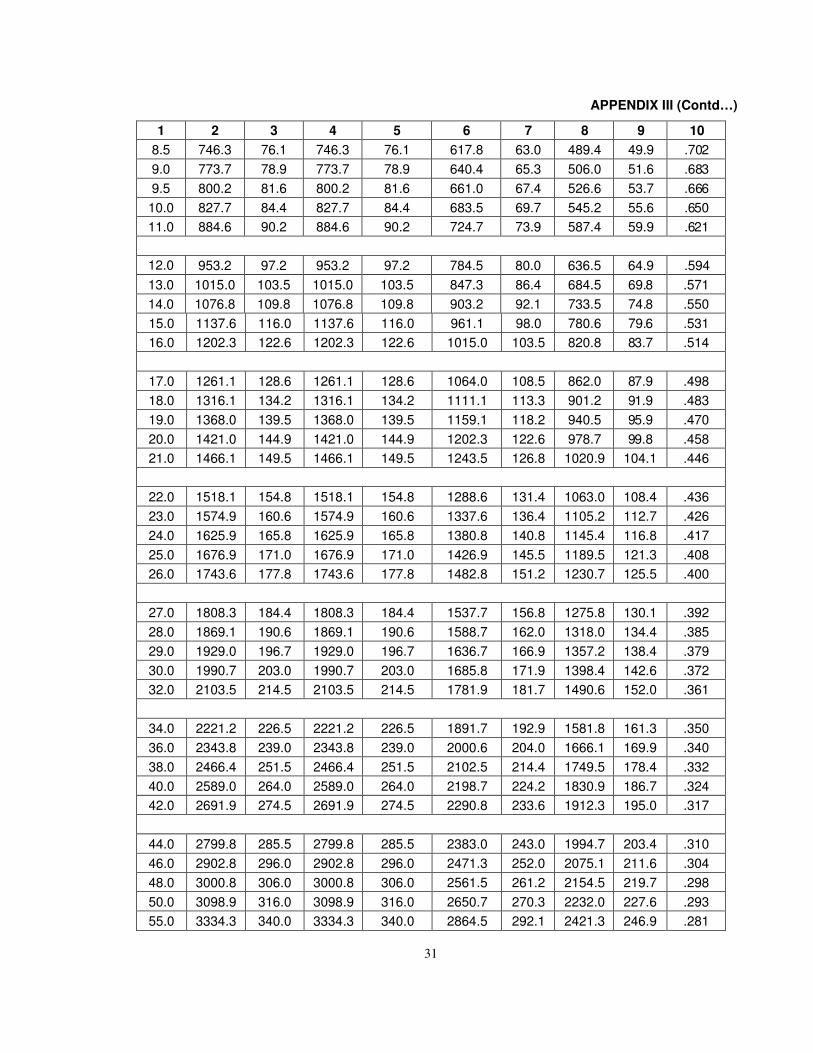
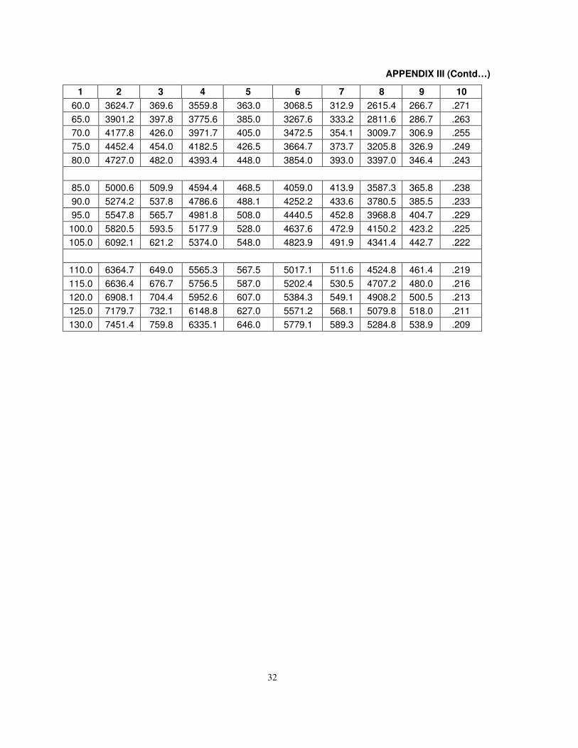
APPENDIX III
METRE GAUGE – 1000 mm
Equivalent Uniformly Distributed Loads (EUDL) in Kilo Newtons (Tonnes) For MG Bridges on each track, and Coefficient of Dynamic Augment (CDA)
For Bending Moment, L is equal to the effective span in metres. For Shear Force, L is the loaded length in metres to give the maximum Shear Force in the member under consideration.
The Equivalent Uniformly Distributed Load (EUDL) for Bending Moment (BM), for spans upto 10m, is that uniformly distributed load which produces the BM at the centre of the span equal to the absolute maximum BM developed under the standard loads. For spans above 10m, the EUDL for BM, is that uniformly distributed load which produces the BM at one-sixth of the span equal to the BM developed at that section under the standard loads.
EUDL for Shear Force (SF) is that uniformly distributed load which produces SF at the end of the span equal to the maximum SF developed under the standard loads at that section.
NOTE:
(1) Cross girders - The live load on a crossgirder will be equal to half the total loadfor bending in a length L, equal to twicethe distance over centres of crossgirders.
(2) L for Coefficient of Dynamic Augment(CDA) shall be as laid down in Clause2.4.1.
(3) When loaded length lies between thevalues given in the table, the EUDL forBending Moment and Shear shall beinterpolated.
L
(m)
Total Load for Bending Moment Impact Factor
CDA= 0.15+
8/(6+L)
MMG Loading-of 1988
ML Standard of 1929
BL Standard of 1929
C Loading of 1929
KN t KN t KN t KN t
1 2 3 4 5 6 7 8 9 10
1.0 313.8 32.0 258.9 26.4 209.9 21.4 158.9 16.2 1.000
1.5 313.8 32.0 258.9 26.4 209.9 21.4 158.9 16.2 1.000
2.0 313.8 32.0 258.9 26.4 209.9 21.4 170.6 17.4 1.000
2.5 313.8 32.0 276.5 28.2 224.6 22.9 197.1 20.1 1.000
3.0 325.6 33.2 313.8 32.0 252.0 25.7 213.7 22.3 1.000
3.5 378.5 38.6 378.5 38.6 306.9 31.3 255.0 26.0 .992
4.0 428.6 43.7 428.6 43.7 347.2 35.4 283.4 28.9 .950
4.5 467.8 47.7 467.8 47.7 378.5 38.6 304.0 31.0 .912
5.0 501.1 51.1 498.2 50.8 403.1 41.1 331.5 33.8 .877
5.5 541.3 55.2 539.4 55.0 437.4 44.6 357.9 36.5 .846
6.0 581.5 59.3 581.5 59.3 470.7 48.0 381.5 38.9 .817
6.5 611.0 62.3 611.0 62.3 498.2 50.8 401.1 40.9 .790
7.0 644.3 65.7 644.3 65.7 531.5 54.2 423.6 43.7 .765
7.5 676.7 69.0 676.7 69.0 564.9 57.6 450.1 45.9 .743
8.0 713.9 72.8 713.9 72.8 593.3 60.5 472.7 48.2 .721
31
APPENDIX III (Contd…)
1 2 3 4 5 6 7 8 9 10
8.5 746.3 76.1 746.3 76.1 617.8 63.0 489.4 49.9 .702
9.0 773.7 78.9 773.7 78.9 640.4 65.3 506.0 51.6 .683
9.5 800.2 81.6 800.2 81.6 661.0 67.4 526.6 53.7 .666
10.0 827.7 84.4 827.7 84.4 683.5 69.7 545.2 55.6 .650
11.0 884.6 90.2 884.6 90.2 724.7 73.9 587.4 59.9 .621
12.0 953.2 97.2 953.2 97.2 784.5 80.0 636.5 64.9 .594
13.0 1015.0 103.5 1015.0 103.5 847.3 86.4 684.5 69.8 .571
14.0 1076.8 109.8 1076.8 109.8 903.2 92.1 733.5 74.8 .550
15.0 1137.6 116.0 1137.6 116.0 961.1 98.0 780.6 79.6 .531
16.0 1202.3 122.6 1202.3 122.6 1015.0 103.5 820.8 83.7 .514
17.0 1261.1 128.6 1261.1 128.6 1064.0 108.5 862.0 87.9 .498
18.0 1316.1 134.2 1316.1 134.2 1111.1 113.3 901.2 91.9 .483
19.0 1368.0 139.5 1368.0 139.5 1159.1 118.2 940.5 95.9 .470
20.0 1421.0 144.9 1421.0 144.9 1202.3 122.6 978.7 99.8 .458
21.0 1466.1 149.5 1466.1 149.5 1243.5 126.8 1020.9 104.1 .446
22.0 1518.1 154.8 1518.1 154.8 1288.6 131.4 1063.0 108.4 .436
23.0 1574.9 160.6 1574.9 160.6 1337.6 136.4 1105.2 112.7 .426
24.0 1625.9 165.8 1625.9 165.8 1380.8 140.8 1145.4 116.8 .417
25.0 1676.9 171.0 1676.9 171.0 1426.9 145.5 1189.5 121.3 .408
26.0 1743.6 177.8 1743.6 177.8 1482.8 151.2 1230.7 125.5 .400
27.0 1808.3 184.4 1808.3 184.4 1537.7 156.8 1275.8 130.1 .392
28.0 1869.1 190.6 1869.1 190.6 1588.7 162.0 1318.0 134.4 .385
29.0 1929.0 196.7 1929.0 196.7 1636.7 166.9 1357.2 138.4 .379
30.0 1990.7 203.0 1990.7 203.0 1685.8 171.9 1398.4 142.6 .372
32.0 2103.5 214.5 2103.5 214.5 1781.9 181.7 1490.6 152.0 .361
34.0 2221.2 226.5 2221.2 226.5 1891.7 192.9 1581.8 161.3 .350
36.0 2343.8 239.0 2343.8 239.0 2000.6 204.0 1666.1 169.9 .340
38.0 2466.4 251.5 2466.4 251.5 2102.5 214.4 1749.5 178.4 .332
40.0 2589.0 264.0 2589.0 264.0 2198.7 224.2 1830.9 186.7 .324
42.0 2691.9 274.5 2691.9 274.5 2290.8 233.6 1912.3 195.0 .317
44.0 2799.8 285.5 2799.8 285.5 2383.0 243.0 1994.7 203.4 .310
46.0 2902.8 296.0 2902.8 296.0 2471.3 252.0 2075.1 211.6 .304
48.0 3000.8 306.0 3000.8 306.0 2561.5 261.2 2154.5 219.7 .298
50.0 3098.9 316.0 3098.9 316.0 2650.7 270.3 2232.0 227.6 .293
55.0 3334.3 340.0 3334.3 340.0 2864.5 292.1 2421.3 246.9 .281
32
APPENDIX III (Contd…)
1 2 3 4 5 6 7 8 9 10
60.0 3624.7 369.6 3559.8 363.0 3068.5 312.9 2615.4 266.7 .271
65.0 3901.2 397.8 3775.6 385.0 3267.6 333.2 2811.6 286.7 .263
70.0 4177.8 426.0 3971.7 405.0 3472.5 354.1 3009.7 306.9 .255
75.0 4452.4 454.0 4182.5 426.5 3664.7 373.7 3205.8 326.9 .249
80.0 4727.0 482.0 4393.4 448.0 3854.0 393.0 3397.0 346.4 .243
85.0 5000.6 509.9 4594.4 468.5 4059.0 413.9 3587.3 365.8 .238
90.0 5274.2 537.8 4786.6 488.1 4252.2 433.6 3780.5 385.5 .233
95.0 5547.8 565.7 4981.8 508.0 4440.5 452.8 3968.8 404.7 .229
100.0 5820.5 593.5 5177.9 528.0 4637.6 472.9 4150.2 423.2 .225
105.0 6092.1 621.2 5374.0 548.0 4823.9 491.9 4341.4 442.7 .222
110.0 6364.7 649.0 5565.3 567.5 5017.1 511.6 4524.8 461.4 .219
115.0 6636.4 676.7 5756.5 587.0 5202.4 530.5 4707.2 480.0 .216
120.0 6908.1 704.4 5952.6 607.0 5384.3 549.1 4908.2 500.5 .213
125.0 7179.7 732.1 6148.8 627.0 5571.2 568.1 5079.8 518.0 .211
130.0 7451.4 759.8 6335.1 646.0 5779.1 589.3 5284.8 538.9 .209
33
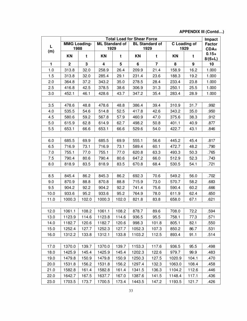
APPENDIX III (Contd…)
L (m)
Total Load for Shear Force Impact Factor
CDA= 0.15+
8/(6+L)
MMG Loading-1988
ML Standard of 1929
BL Standard of 1929
C Loading of 1929
KN t KN t KN t KN t
1 2 3 4 5 6 7 8 9 10
1.0 313.8 32.0 258.9 26.4 209.9 21.4 158.9 16.2 1.000
1.5 313.8 32.0 285.4 29.1 231.4 23.6 188.3 19.2 1.000
2.0 364.8 37.2 343.2 35.0 278.5 28.4 233.4 23.8 1.000
2.5 416.8 42.5 378.5 38.6 306.9 31.3 250.1 25.5 1.000
3.0 452.1 46.1 428.6 43.7 347.2 35.4 283.4 28.9 1.000
3.5 478.6 48.8 478.6 48.8 386.4 39.4 310.9 31.7 .992
4.0 535.5 54.6 514.8 52.5 417.8 42.6 343.2 35.0 .950
4.5 580.6 59.2 567.8 57.9 460.9 47.0 375.6 38.3 .912
5.0 615.9 62.8 614.9 62.7 498.2 50.8 401.1 40.9 .877
5.5 653.1 66.6 653.1 66.6 529.6 54.0 422.7 43.1 .846
6.0 685.5 69.9 685.5 69.9 555.1 56.6 445.2 45.4 .817
6.5 716.9 73.1 716.9 73.1 589.4 60.1 472.7 48.2 .790
7.0 755.1 77.0 755.1 77.0 620.8 63.3 493.3 50.3 .765
7.5 790.4 80.6 790.4 80.6 647.2 66.0 512.9 52.3 .743
8.0 818.9 83.5 818.9 83.5 670.8 68.4 530.5 54.1 .721
8.5 845.4 86.2 845.3 86.2 692.3 70.6 549.2 56.0 .702
9.0 870.9 88.8 870.8 88.8 715.9 73.0 570.7 58.2 .683
9.5 904.2 92.2 904.2 92.2 741.4 75.6 590.4 60.2 .666
10.0 933.6 95.2 933.6 95.2 764.9 78.0 611.9 62.4 .650
11.0 1000.3 102.0 1000.3 102.0 821.8 83.8 658.0 67.1 .621
12.0 1061.1 108.2 1061.1 108.2 878.7 89.6 708.0 72.2 .594
13.0 1123.9 114.6 1123.8 114.6 936.5 95.5 758.1 77.3 .571
14.0 1182.7 120.6 1182.7 120.6 998.3 101.8 805.1 82.1 .550
15.0 1252.4 127.7 1252.3 127.7 1052.3 107.3 850.2 86.7 .531
16.0 1312.2 133.8 1312.1 133.8 1103.2 112.5 893.4 91.1 .514
17.0 1370.0 139.7 1370.0 139.7 1153.3 117.6 936.5 95.5 .498
18.0 1425.9 145.4 1425.9 145.4 1202.3 122.6 979.7 99.9 .483
19.0 1479.8 150.9 1479.8 150.9 1250.3 127.5 1020.9 104.1 .470
20.0 1531.8 156.2 1531.8 156.2 1297.4 132.3 1063.0 108.4 .458
21.0 1582.8 161.4 1582.8 161.4 1341.5 136.3 1104.2 112.6 .446
22.0 1642.7 167.5 1637.7 167.0 1387.6 141.5 1148.4 117.1 .436
23.0 1703.5 173.7 1700.5 173.4 1443.5 147.2 1193.5 121.7 .426
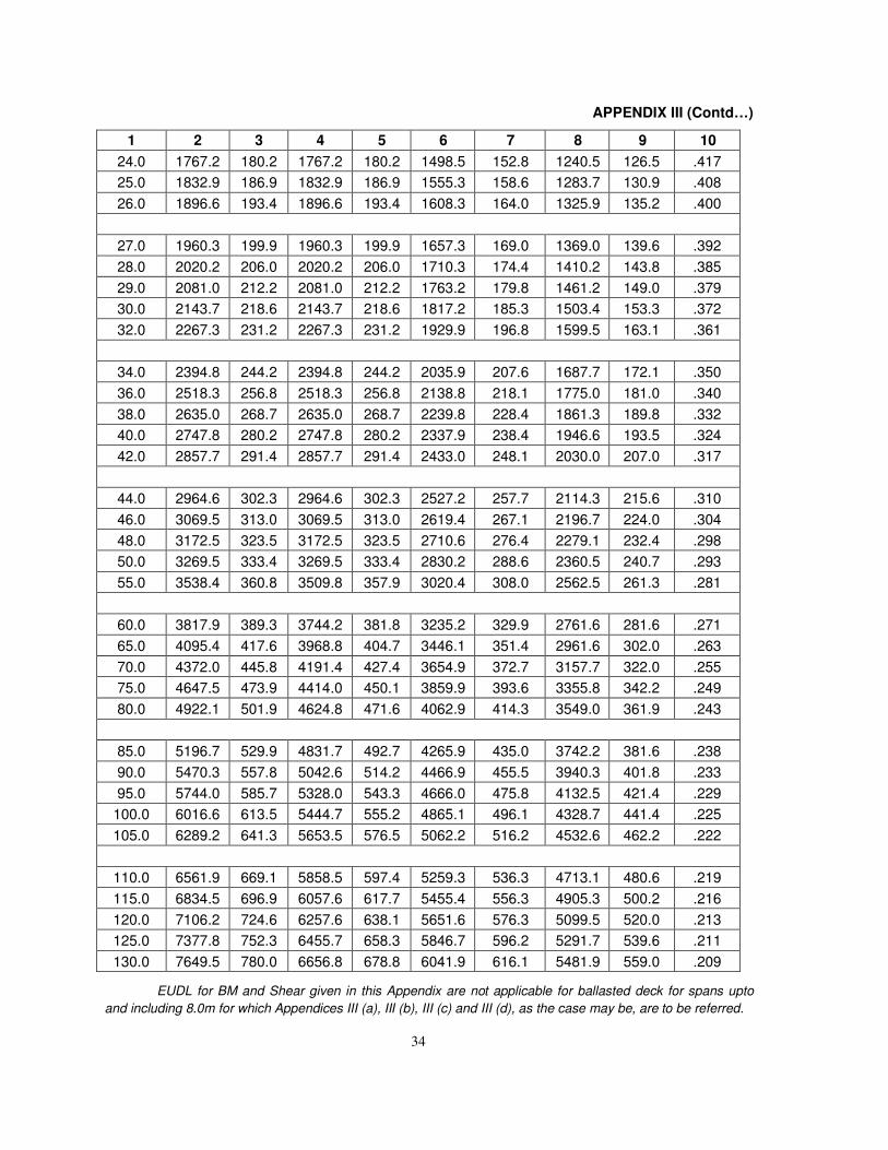
34
APPENDIX III (Contd…)
1 2 3 4 5 6 7 8 9 10
24.0 1767.2 180.2 1767.2 180.2 1498.5 152.8 1240.5 126.5 .417
25.0 1832.9 186.9 1832.9 186.9 1555.3 158.6 1283.7 130.9 .408
26.0 1896.6 193.4 1896.6 193.4 1608.3 164.0 1325.9 135.2 .400
27.0 1960.3 199.9 1960.3 199.9 1657.3 169.0 1369.0 139.6 .392
28.0 2020.2 206.0 2020.2 206.0 1710.3 174.4 1410.2 143.8 .385
29.0 2081.0 212.2 2081.0 212.2 1763.2 179.8 1461.2 149.0 .379
30.0 2143.7 218.6 2143.7 218.6 1817.2 185.3 1503.4 153.3 .372
32.0 2267.3 231.2 2267.3 231.2 1929.9 196.8 1599.5 163.1 .361
34.0 2394.8 244.2 2394.8 244.2 2035.9 207.6 1687.7 172.1 .350
36.0 2518.3 256.8 2518.3 256.8 2138.8 218.1 1775.0 181.0 .340
38.0 2635.0 268.7 2635.0 268.7 2239.8 228.4 1861.3 189.8 .332
40.0 2747.8 280.2 2747.8 280.2 2337.9 238.4 1946.6 193.5 .324
42.0 2857.7 291.4 2857.7 291.4 2433.0 248.1 2030.0 207.0 .317
44.0 2964.6 302.3 2964.6 302.3 2527.2 257.7 2114.3 215.6 .310
46.0 3069.5 313.0 3069.5 313.0 2619.4 267.1 2196.7 224.0 .304
48.0 3172.5 323.5 3172.5 323.5 2710.6 276.4 2279.1 232.4 .298
50.0 3269.5 333.4 3269.5 333.4 2830.2 288.6 2360.5 240.7 .293
55.0 3538.4 360.8 3509.8 357.9 3020.4 308.0 2562.5 261.3 .281
60.0 3817.9 389.3 3744.2 381.8 3235.2 329.9 2761.6 281.6 .271
65.0 4095.4 417.6 3968.8 404.7 3446.1 351.4 2961.6 302.0 .263
70.0 4372.0 445.8 4191.4 427.4 3654.9 372.7 3157.7 322.0 .255
75.0 4647.5 473.9 4414.0 450.1 3859.9 393.6 3355.8 342.2 .249
80.0 4922.1 501.9 4624.8 471.6 4062.9 414.3 3549.0 361.9 .243
85.0 5196.7 529.9 4831.7 492.7 4265.9 435.0 3742.2 381.6 .238
90.0 5470.3 557.8 5042.6 514.2 4466.9 455.5 3940.3 401.8 .233
95.0 5744.0 585.7 5328.0 543.3 4666.0 475.8 4132.5 421.4 .229
100.0 6016.6 613.5 5444.7 555.2 4865.1 496.1 4328.7 441.4 .225
105.0 6289.2 641.3 5653.5 576.5 5062.2 516.2 4532.6 462.2 .222
110.0 6561.9 669.1 5858.5 597.4 5259.3 536.3 4713.1 480.6 .219
115.0 6834.5 696.9 6057.6 617.7 5455.4 556.3 4905.3 500.2 .216
120.0 7106.2 724.6 6257.6 638.1 5651.6 576.3 5099.5 520.0 .213
125.0 7377.8 752.3 6455.7 658.3 5846.7 596.2 5291.7 539.6 .211
130.0 7649.5 780.0 6656.8 678.8 6041.9 616.1 5481.9 559.0 .209
EUDL for BM and Shear given in this Appendix are not applicable for ballasted deck for spans upto
and including 8.0m for which Appendices III (a), III (b), III (c) and III (d), as the case may be, are to be referred.
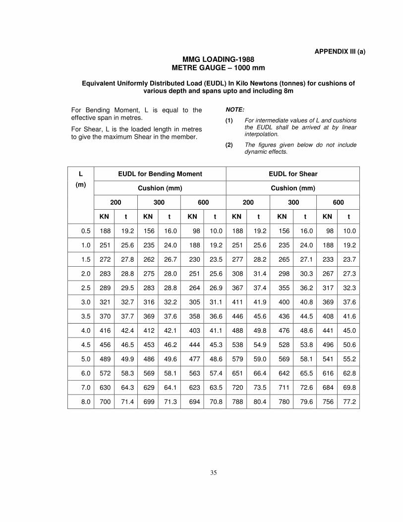
35
APPENDIX III (a)
MMG LOADING-1988 METRE GAUGE – 1000 mm
Equivalent Uniformly Distributed Load (EUDL) In Kilo Newtons (tonnes) for cushions of various depth and spans upto and including 8m
For Bending Moment, L is equal to the effective span in metres.
For Shear, L is the loaded length in metres to give the maximum Shear in the member.
NOTE:
(1) For intermediate values of L and cushionsthe EUDL shall be arrived at by linearinterpolation.
(2) The figures given below do not includedynamic effects.
L
(m)
EUDL for Bending Moment EUDL for Shear
Cushion (mm) Cushion (mm)
200 300 600 200 300 600
KN t KN t KN t KN t KN t KN t
0.5 188 19.2 156 16.0 98 10.0 188 19.2 156 16.0 98 10.0
1.0 251 25.6 235 24.0 188 19.2 251 25.6 235 24.0 188 19.2
1.5 272 27.8 262 26.7 230 23.5 277 28.2 265 27.1 233 23.7
2.0 283 28.8 275 28.0 251 25.6 308 31.4 298 30.3 267 27.3
2.5 289 29.5 283 28.8 264 26.9 367 37.4 355 36.2 317 32.3
3.0 321 32.7 316 32.2 305 31.1 411 41.9 400 40.8 369 37.6
3.5 370 37.7 369 37.6 358 36.6 446 45.6 436 44.5 408 41.6
4.0 416 42.4 412 42.1 403 41.1 488 49.8 476 48.6 441 45.0
4.5 456 46.5 453 46.2 444 45.3 538 54.9 528 53.8 496 50.6
5.0 489 49.9 486 49.6 477 48.6 579 59.0 569 58.1 541 55.2
6.0 572 58.3 569 58.1 563 57.4 651 66.4 642 65.5 616 62.8
7.0 630 64.3 629 64.1 623 63.5 720 73.5 711 72.6 684 69.8
8.0 700 71.4 699 71.3 694 70.8 788 80.4 780 79.6 756 77.2
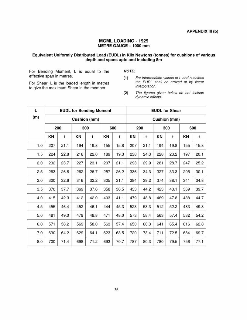
36
APPENDIX III (b)
MGML LOADING - 1929 METRE GAUGE – 1000 mm
Equivalent Uniformly Distributed Load (EUDL) in Kilo Newtons (tonnes) for cushions of various depth and spans upto and including 8m
For Bending Moment, L is equal to the effective span in metres.
For Shear, L is the loaded length in metres to give the maximum Shear in the member.
NOTE:
(1) For intermediate values of L and cushionsthe EUDL shall be arrived at by linearinterpolation.
(2) The figures given below do not includedynamic effects.
L
(m)
EUDL for Bending Moment EUDL for Shear
Cushion (mm) Cushion (mm)
200 300 600 200 300 600
KN t KN t KN t KN t KN t KN t
1.0 207 21.1 194 19.8 155 15.8 207 21.1 194 19.8 155 15.8
1.5 224 22.8 216 22.0 189 19.3 238 24.3 228 23.2 197 20.1
2.0 232 23.7 227 23.1 207 21.1 293 29.9 281 28.7 247 25.2
2.5 263 26.8 262 26.7 257 26.2 336 34.3 327 33.3 295 30.1
3.0 320 32.6 316 32.2 305 31.1 384 39.2 374 38.1 341 34.8
3.5 370 37.7 369 37.6 358 36.5 433 44.2 423 43.1 369 39.7
4.0 415 42.3 412 42.0 403 41.1 479 48.8 469 47.8 438 44.7
4.5 455 46.4 452 46.1 444 45.3 523 53.3 512 52.2 483 49.3
5.0 481 49.0 479 48.8 471 48.0 573 58.4 563 57.4 532 54.2
6.0 571 58.2 569 58.0 563 57.4 650 66.3 641 65.4 616 62.8
7.0 630 64.2 629 64.1 623 63.5 720 73.4 711 72.5 684 69.7
8.0 700 71.4 698 71.2 693 70.7 787 80.3 780 79.5 756 77.1
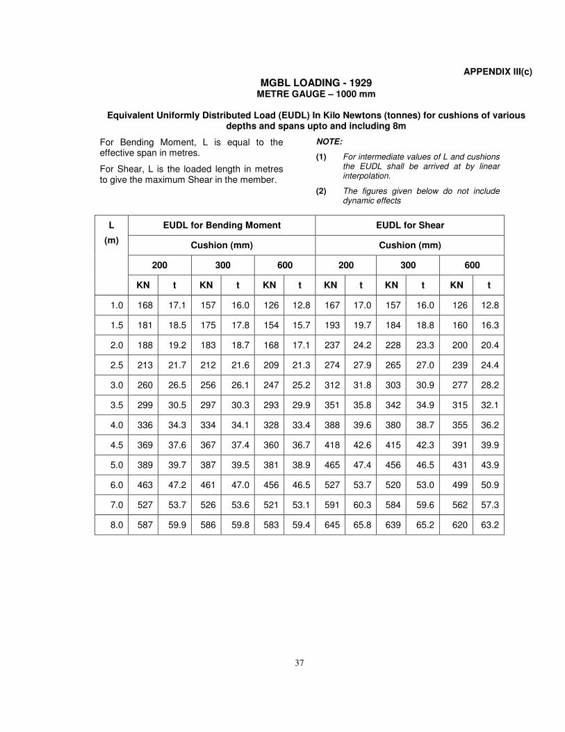
37
APPENDIX III(c)
MGBL LOADING - 1929 METRE GAUGE – 1000 mm
Equivalent Uniformly Distributed Load (EUDL) In Kilo Newtons (tonnes) for cushions of various depths and spans upto and including 8m
For Bending Moment, L is equal to the effective span in metres.
For Shear, L is the loaded length in metres to give the maximum Shear in the member.
NOTE:
(1) For intermediate values of L and cushionsthe EUDL shall be arrived at by linearinterpolation.
(2) The figures given below do not includedynamic effects
L
(m)
EUDL for Bending Moment EUDL for Shear
Cushion (mm) Cushion (mm)
200 300 600 200 300 600
KN t KN t KN t KN t KN t KN t
1.0 168 17.1 157 16.0 126 12.8 167 17.0 157 16.0 126 12.8
1.5 181 18.5 175 17.8 154 15.7 193 19.7 184 18.8 160 16.3
2.0 188 19.2 183 18.7 168 17.1 237 24.2 228 23.3 200 20.4
2.5 213 21.7 212 21.6 209 21.3 274 27.9 265 27.0 239 24.4
3.0 260 26.5 256 26.1 247 25.2 312 31.8 303 30.9 277 28.2
3.5 299 30.5 297 30.3 293 29.9 351 35.8 342 34.9 315 32.1
4.0 336 34.3 334 34.1 328 33.4 388 39.6 380 38.7 355 36.2
4.5 369 37.6 367 37.4 360 36.7 418 42.6 415 42.3 391 39.9
5.0 389 39.7 387 39.5 381 38.9 465 47.4 456 46.5 431 43.9
6.0 463 47.2 461 47.0 456 46.5 527 53.7 520 53.0 499 50.9
7.0 527 53.7 526 53.6 521 53.1 591 60.3 584 59.6 562 57.3
8.0 587 59.9 586 59.8 583 59.4 645 65.8 639 65.2 620 63.2
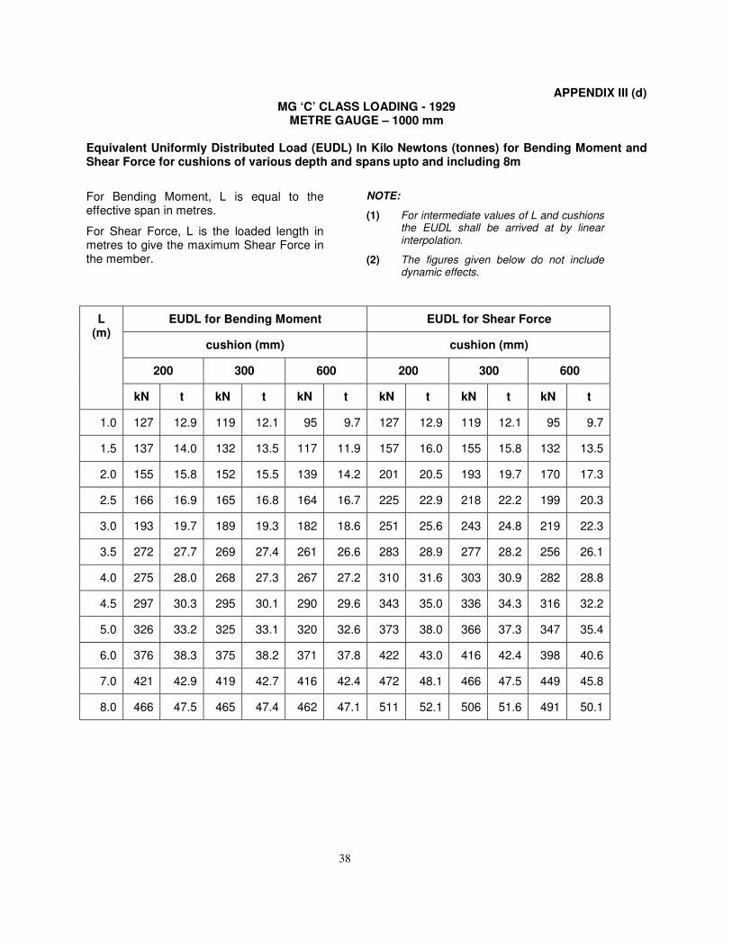
38
APPENDIX III (d) MG ‘C’ CLASS LOADING - 1929
METRE GAUGE – 1000 mm
Equivalent Uniformly Distributed Load (EUDL) In Kilo Newtons (tonnes) for Bending Moment and Shear Force for cushions of various depth and spans upto and including 8m
For Bending Moment, L is equal to the effective span in metres.
For Shear Force, L is the loaded length in metres to give the maximum Shear Force in the member.
NOTE:
(1) For intermediate values of L and cushions the EUDL shall be arrived at by linear interpolation.
(2) The figures given below do not include dynamic effects.
L (m)
EUDL for Bending Moment EUDL for Shear Force
cushion (mm) cushion (mm)
200 300 600 200 300 600
kN t kN t kN t kN t kN t kN t
1.0 127 12.9 119 12.1 95 9.7 127 12.9 119 12.1 95 9.7
1.5 137 14.0 132 13.5 117 11.9 157 16.0 155 15.8 132 13.5
2.0 155 15.8 152 15.5 139 14.2 201 20.5 193 19.7 170 17.3
2.5 166 16.9 165 16.8 164 16.7 225 22.9 218 22.2 199 20.3
3.0 193 19.7 189 19.3 182 18.6 251 25.6 243 24.8 219 22.3
3.5 272 27.7 269 27.4 261 26.6 283 28.9 277 28.2 256 26.1
4.0 275 28.0 268 27.3 267 27.2 310 31.6 303 30.9 282 28.8
4.5 297 30.3 295 30.1 290 29.6 343 35.0 336 34.3 316 32.2
5.0 326 33.2 325 33.1 320 32.6 373 38.0 366 37.3 347 35.4
6.0 376 38.3 375 38.2 371 37.8 422 43.0 416 42.4 398 40.6
7.0 421 42.9 419 42.7 416 42.4 472 48.1 466 47.5 449 45.8
8.0 466 47.5 465 47.4 462 47.1 511 52.1 506 51.6 491 50.1
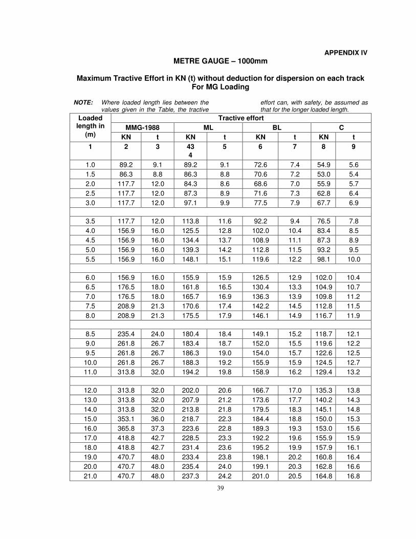
39
APPENDIX IV
METRE GAUGE – 1000mm
Maximum Tractive Effort in KN (t) without deduction for dispersion on each track For MG Loading
NOTE: Where loaded length lies between the values given in the Table, the tractive
effort can, with safety, be assumed as that for the longer loaded length.
Loaded length in
(m)
Tractive effort
MMG-1988 ML BL C
KN t KN t KN t KN t
1 2 3 43
4
5 6 7 8 9
1.0 89.2 9.1 89.2 9.1 72.6 7.4 54.9 5.6
1.5 86.3 8.8 86.3 8.8 70.6 7.2 53.0 5.4
2.0 117.7 12.0 84.3 8.6 68.6 7.0 55.9 5.7
2.5 117.7 12.0 87.3 8.9 71.6 7.3 62.8 6.4
3.0 117.7 12.0 97.1 9.9 77.5 7.9 67.7 6.9
3.5 117.7 12.0 113.8 11.6 92.2 9.4 76.5 7.8
4.0 156.9 16.0 125.5 12.8 102.0 10.4 83.4 8.5
4.5 156.9 16.0 134.4 13.7 108.9 11.1 87.3 8.9
5.0 156.9 16.0 139.3 14.2 112.8 11.5 93.2 9.5
5.5 156.9 16.0 148.1 15.1 119.6 12.2 98.1 10.0
6.0 156.9 16.0 155.9 15.9 126.5 12.9 102.0 10.4
6.5 176.5 18.0 161.8 16.5 130.4 13.3 104.9 10.7
7.0 176.5 18.0 165.7 16.9 136.3 13.9 109.8 11.2
7.5 208.9 21.3 170.6 17.4 142.2 14.5 112.8 11.5
8.0 208.9 21.3 175.5 17.9 146.1 14.9 116.7 11.9
8.5 235.4 24.0 180.4 18.4 149.1 15.2 118.7 12.1
9.0 261.8 26.7 183.4 18.7 152.0 15.5 119.6 12.2
9.5 261.8 26.7 186.3 19.0 154.0 15.7 122.6 12.5
10.0 261.8 26.7 188.3 19.2 155.9 15.9 124.5 12.7
11.0 313.8 32.0 194.2 19.8 158.9 16.2 129.4 13.2
12.0 313.8 32.0 202.0 20.6 166.7 17.0 135.3 13.8
13.0 313.8 32.0 207.9 21.2 173.6 17.7 140.2 14.3
14.0 313.8 32.0 213.8 21.8 179.5 18.3 145.1 14.8
15.0 353.1 36.0 218.7 22.3 184.4 18.8 150.0 15.3
16.0 365.8 37.3 223.6 22.8 189.3 19.3 153.0 15.6
17.0 418.8 42.7 228.5 23.3 192.2 19.6 155.9 15.9
18.0 418.8 42.7 231.4 23.6 195.2 19.9 157.9 16.1
19.0 470.7 48.0 233.4 23.8 198.1 20.2 160.8 16.4
20.0 470.7 48.0 235.4 24.0 199.1 20.3 162.8 16.6
21.0 470.7 48.0 237.3 24.2 201.0 20.5 164.8 16.8
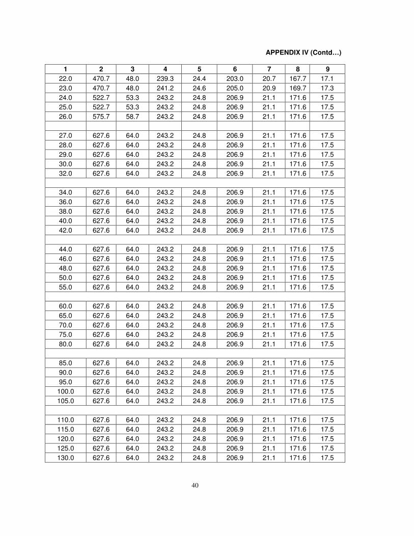
40
APPENDIX IV (Contd…)
1 2 3 4 5 6 7 8 9
22.0 470.7 48.0 239.3 24.4 203.0 20.7 167.7 17.1
23.0 470.7 48.0 241.2 24.6 205.0 20.9 169.7 17.3
24.0 522.7 53.3 243.2 24.8 206.9 21.1 171.6 17.5
25.0 522.7 53.3 243.2 24.8 206.9 21.1 171.6 17.5
26.0 575.7 58.7 243.2 24.8 206.9 21.1 171.6 17.5
27.0 627.6 64.0 243.2 24.8 206.9 21.1 171.6 17.5
28.0 627.6 64.0 243.2 24.8 206.9 21.1 171.6 17.5
29.0 627.6 64.0 243.2 24.8 206.9 21.1 171.6 17.5
30.0 627.6 64.0 243.2 24.8 206.9 21.1 171.6 17.5
32.0 627.6 64.0 243.2 24.8 206.9 21.1 171.6 17.5
34.0 627.6 64.0 243.2 24.8 206.9 21.1 171.6 17.5
36.0 627.6 64.0 243.2 24.8 206.9 21.1 171.6 17.5
38.0 627.6 64.0 243.2 24.8 206.9 21.1 171.6 17.5
40.0 627.6 64.0 243.2 24.8 206.9 21.1 171.6 17.5
42.0 627.6 64.0 243.2 24.8 206.9 21.1 171.6 17.5
44.0 627.6 64.0 243.2 24.8 206.9 21.1 171.6 17.5
46.0 627.6 64.0 243.2 24.8 206.9 21.1 171.6 17.5
48.0 627.6 64.0 243.2 24.8 206.9 21.1 171.6 17.5
50.0 627.6 64.0 243.2 24.8 206.9 21.1 171.6 17.5
55.0 627.6 64.0 243.2 24.8 206.9 21.1 171.6 17.5
60.0 627.6 64.0 243.2 24.8 206.9 21.1 171.6 17.5
65.0 627.6 64.0 243.2 24.8 206.9 21.1 171.6 17.5
70.0 627.6 64.0 243.2 24.8 206.9 21.1 171.6 17.5
75.0 627.6 64.0 243.2 24.8 206.9 21.1 171.6 17.5
80.0 627.6 64.0 243.2 24.8 206.9 21.1 171.6 17.5
85.0 627.6 64.0 243.2 24.8 206.9 21.1 171.6 17.5
90.0 627.6 64.0 243.2 24.8 206.9 21.1 171.6 17.5
95.0 627.6 64.0 243.2 24.8 206.9 21.1 171.6 17.5
100.0 627.6 64.0 243.2 24.8 206.9 21.1 171.6 17.5
105.0 627.6 64.0 243.2 24.8 206.9 21.1 171.6 17.5
110.0 627.6 64.0 243.2 24.8 206.9 21.1 171.6 17.5
115.0 627.6 64.0 243.2 24.8 206.9 21.1 171.6 17.5
120.0 627.6 64.0 243.2 24.8 206.9 21.1 171.6 17.5
125.0 627.6 64.0 243.2 24.8 206.9 21.1 171.6 17.5
130.0 627.6 64.0 243.2 24.8 206.9 21.1 171.6 17.5
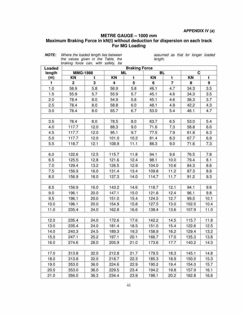
41
APPENDIX IV (a)
METRE GAUGE – 1000 mm Maximum Braking Force in kN(t) without deduction for dispersion on each track
For MG Loading
NOTE: Where the loaded length lies between the values given in the Table, the braking force can, with safety, be
assumed as that for longer loaded length.
Loaded length
(m)
Braking Force
MMG-1988 ML BL C
KN t KN t KN t KN t
1 2 3 4 5 6 7 8 9
1.0 56.9 5.8 56.9 5.8 46.1 4.7 34.3 3.5
1.5 55.9 5.7 55.9 5.7 45.1 4.6 34.3 3.5
2.0 78.4 8.0 54.9 5.6 45.1 4.6 36.3 3.7
2.5 78.4 8.0 58.8 6.0 48.1 4.9 42.2 4.3
3.0 78.4 8.0 65.7 6.7 53.0 5.4 46.1 4.7
3.5 78.4 8.0 78.5 8.0 63.7 6.5 53.0 5.4
4.0 117.7 12.0 88.3 9.0 71.6 7.3 58.8 6.0
4.5 117.7 12.0 95.1 9.7 77.5 7.9 61.8 6.3
5.0 117.7 12.0 101.0 10.3 81.4 8.3 67.7 6.9
5.5 118.7 12.1 108.9 11.1 88.3 9.0 71.6 7.3
6.0 122.6 12.5 115.7 11.8 94.1 9.6 76.5 7.8
6.5 125.5 12.8 121.6 12.4 98.1 10.0 79.4 8.1
7.0 129.4 13.2 126.5 12.9 104.0 10.6 84.3 8.6
7.5 156.9 16.0 131.4 13.4 109.8 11.2 87.3 8.9
8.0 156.9 16.0 137.3 14.0 114.7 11.7 91.2 9.3
8.5 156.9 16.0 143.2 14.6 118.7 12.1 94.1 9.6
9.0 196.1 20.0 147.1 15.0 121.6 12.4 96.1 9.8
9.5 196.1 20.0 151.0 15.4 124.5 12.7 99.0 10.1
10.0 196.1 20.0 154.9 15.8 127.5 13.0 102.0 10.4
11.0 235.4 24.0 162.8 16.6 138.4 13.6 107.9 11.0
12.0 235.4 24.0 172.6 17.6 142.2 14.5 115.7 11.8
13.0 235.4 24.0 181.4 18.5 151.0 15.4 122.6 12.5
14.0 240.3 24.5 189.3 19.3 158.9 16.2 129.4 13.2
15.0 247.1 25.2 197.1 20.1 166.7 17.0 135.3 13.8
16.0 274.6 28.0 205.9 21.0 173.6 17.7 140.2 14.3
17.0 313.8 32.0 212.8 21.7 179.5 18.3 145.1 14.8
18.0 313.8 32.0 218.7 22.3 185.3 18.9 150.0 15.3
19.0 353.0 36.0 224.6 22.9 190.2 19.4 154.0 15.7
20.0 353.0 36.0 229.5 23.4 194.2 19.8 157.9 16.1
21.0 356.0 36.3 234.4 23.9 198.1 20.2 162.8 16.6
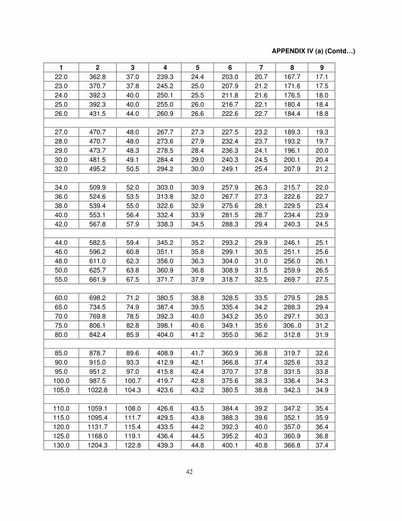
42
APPENDIX IV (a) (Contd…)
1 2 3 4 5 6 7 8 9
22.0 362.8 37.0 239.3 24.4 203.0 20.7 167.7 17.1
23.0 370.7 37.8 245.2 25.0 207.9 21.2 171.6 17.5
24.0 392.3 40.0 250.1 25.5 211.8 21.6 176.5 18.0
25.0 392.3 40.0 255.0 26.0 216.7 22.1 180.4 18.4
26.0 431.5 44.0 260.9 26.6 222.6 22.7 184.4 18.8
27.0 470.7 48.0 267.7 27.3 227.5 23.2 189.3 19.3
28.0 470.7 48.0 273.6 27.9 232.4 23.7 193.2 19.7
29.0 473.7 48.3 278.5 28.4 236.3 24.1 196.1 20.0
30.0 481.5 49.1 284.4 29.0 240.3 24.5 200.1 20.4
32.0 495.2 50.5 294.2 30.0 249.1 25.4 207.9 21.2
34.0 509.9 52.0 303.0 30.9 257.9 26.3 215.7 22.0
36.0 524.6 53.5 313.8 32.0 267.7 27.3 222.6 22.7
38.0 539.4 55.0 322.6 32.9 275.6 28.1 229.5 23.4
40.0 553.1 56.4 332.4 33.9 281.5 28.7 234.4 23.9
42.0 567.8 57.9 338.3 34.5 288.3 29.4 240.3 24.5
44.0 582.5 59.4 345.2 35.2 293.2 29.9 246.1 25.1
46.0 596.2 60.8 351.1 35.8 299.1 30.5 251.1 25.6
48.0 611.0 62.3 356.0 36.3 304.0 31.0 256.0 26.1
50.0 625.7 63.8 360.9 36.8 308.9 31.5 259.9 26.5
55.0 661.9 67.5 371.7 37.9 318.7 32.5 269.7 27.5
60.0 698.2 71.2 380.5 38.8 328.5 33.5 279.5 28.5
65.0 734.5 74.9 387.4 39.5 335.4 34.2 288.3 29.4
70.0 769.8 78.5 392.3 40.0 343.2 35.0 297.1 30.3
75.0 806.1 82.8 398.1 40.6 349.1 35.6 306..0 31.2
80.0 842.4 85.9 404.0 41.2 355.0 36.2 312.8 31.9
85.0 878.7 89.6 408.9 41.7 360.9 36.8 319.7 32.6
90.0 915.0 93.3 412.9 42.1 366.8 37.4 325.6 33.2
95.0 951.2 97.0 415.8 42.4 370.7 37.8 331.5 33.8
100.0 987.5 100.7 419.7 42.8 375.6 38.3 336.4 34.3
105.0 1022.8 104.3 423.6 43.2 380.5 38.8 342.3 34.9
110.0 1059.1 108.0 426.6 43.5 384.4 39.2 347.2 35.4
115.0 1095.4 111.7 429.5 43.8 388.3 39.6 352.1 35.9
120.0 1131.7 115.4 433.5 44.2 392.3 40.0 357.0 36.4
125.0 1168.0 119.1 436.4 44.5 395.2 40.3 360.9 36.8
130.0 1204.3 122.8 439.3 44.8 400.1 40.8 366.8 37.4
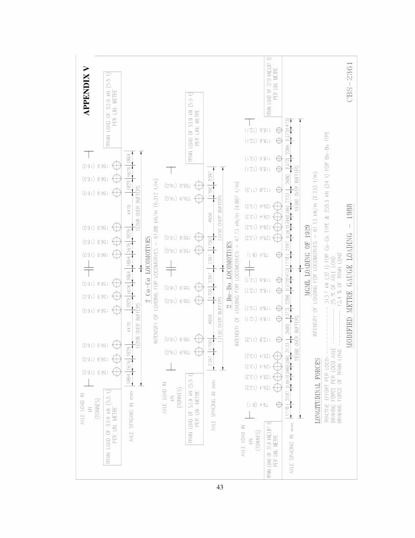
43
AP
PE
ND
IX V
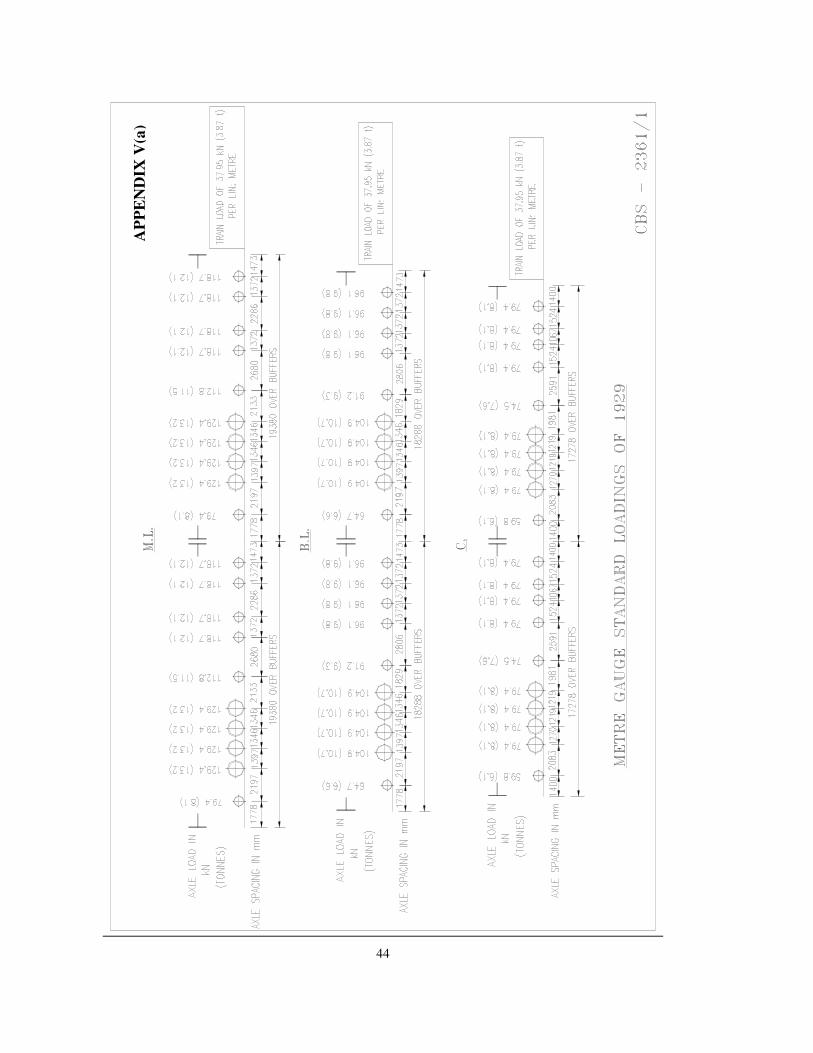
44
AP
PE
ND
IX V
(a)
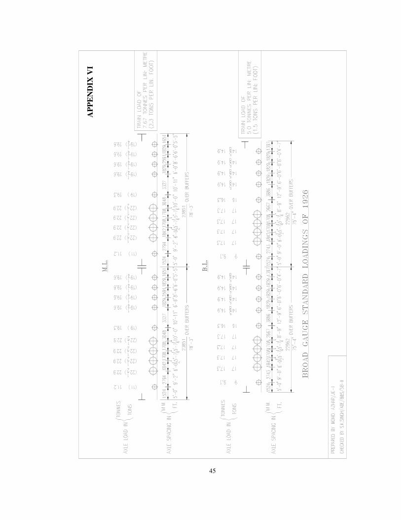
45
AP
PE
ND
IX V
I
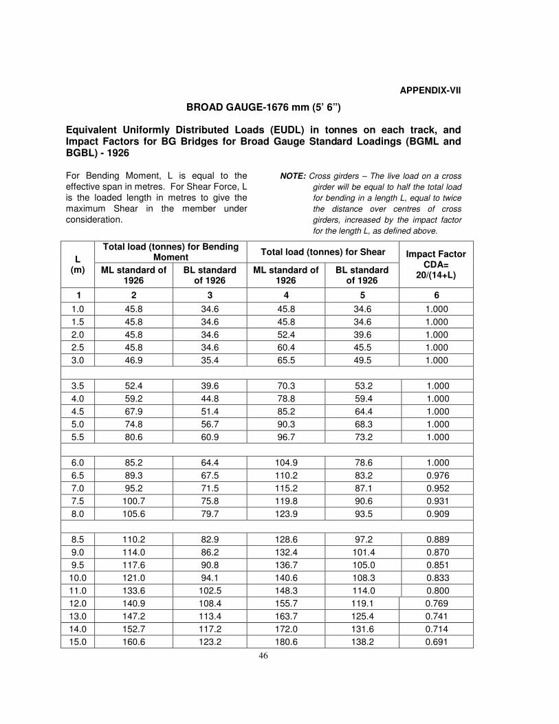
46
APPENDIX-VII
BROAD GAUGE-1676 mm (5’ 6”)
Equivalent Uniformly Distributed Loads (EUDL) in tonnes on each track, and Impact Factors for BG Bridges for Broad Gauge Standard Loadings (BGML and BGBL) - 1926
For Bending Moment, L is equal to the
effective span in metres. For Shear Force, L
is the loaded length in metres to give the
maximum Shear in the member under
consideration.
NOTE: Cross girders – The live load on a cross
girder will be equal to half the total load
for bending in a length L, equal to twice
the distance over centres of cross
girders, increased by the impact factor
for the length L, as defined above.
L (m)
Total load (tonnes) for Bending Moment
Total load (tonnes) for Shear Impact Factor CDA=
20/(14+L) ML standard of
1926 BL standard
of 1926 ML standard of
1926 BL standard
of 1926
1 2 3 4 5 6
1.0 45.8 34.6 45.8 34.6 1.000
1.5 45.8 34.6 45.8 34.6 1.000
2.0 45.8 34.6 52.4 39.6 1.000
2.5 45.8 34.6 60.4 45.5 1.000
3.0 46.9 35.4 65.5 49.5 1.000
3.5 52.4 39.6 70.3 53.2 1.000
4.0 59.2 44.8 78.8 59.4 1.000
4.5 67.9 51.4 85.2 64.4 1.000
5.0 74.8 56.7 90.3 68.3 1.000
5.5 80.6 60.9 96.7 73.2 1.000
6.0 85.2 64.4 104.9 78.6 1.000
6.5 89.3 67.5 110.2 83.2 0.976
7.0 95.2 71.5 115.2 87.1 0.952
7.5 100.7 75.8 119.8 90.6 0.931
8.0 105.6 79.7 123.9 93.5 0.909
8.5 110.2 82.9 128.6 97.2 0.889
9.0 114.0 86.2 132.4 101.4 0.870
9.5 117.6 90.8 136.7 105.0 0.851
10.0 121.0 94.1 140.6 108.3 0.833
11.0 133.6 102.5 148.3 114.0 0.800
12.0 140.9 108.4 155.7 119.1 0.769
13.0 147.2 113.4 163.7 125.4 0.741
14.0 152.7 117.2 172.0 131.6 0.714
15.0 160.6 123.2 180.6 138.2 0.691
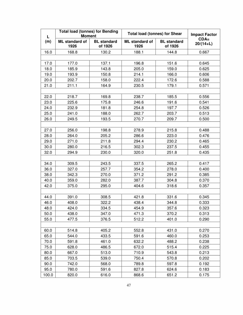
47
L (m)
Total load (tonnes) for Bending Moment
Total load (tonnes) for Shear Impact Factor CDA=
20/(14+L) ML standard of
1926 BL standard
of 1926 ML standard of
1926 BL standard
of 1926
16.0 168.8 130.2 188.1 144.8 0.667
17.0 177.0 137.1 196.8 151.6 0.645
18.0 185.9 143.8 205.0 159.0 0.625
19.0 193.9 150.8 214.1 166.0 0.606
20.0 202.7 158.0 222.4 172.6 0.588
21.0 211.1 164.9 230.5 179.1 0.571
22.0 218.7 169.8 238.7 185.5 0.556
23.0 225.6 175.8 246.6 191.6 0.541
24.0 232.9 181.8 254.8 197.7 0.526
25.0 241.0 188.0 262.7 203.7 0.513
26.0 249.5 193.5 270.7 209.7 0.500
27.0 256.0 198.8 278.9 215.8 0.488
28.0 264.0 205.2 286.6 223.0 0.476
29.0 271.0 211.8 294.4 230.2 0.465
30.0 280.0 216.5 302.3 237.5 0.455
32.0 294.9 230.0 320.0 251.8 0.435
34.0 309.5 243.5 337.5 265.2 0.417
36.0 327.0 257.7 354.2 278.0 0.400
38.0 342.3 270.0 371.2 291.2 0.385
40.0 359.0 282.0 387.7 304.8 0.370
42.0 375.0 295.0 404.6 318.6 0.357
44.0 391.0 308.5 421.8 331.6 0.345
46.0 408.0 322.2 438.4 344.8 0.333
48.0 424.0 334.5 454.9 357.6 0.323
50.0 438.0 347.0 471.3 370.2 0.313
55.0 477.5 376.5 512.2 401.0 0.290
60.0 514.8 405.2 552.8 431.0 0.270
65.0 544.0 433.5 591.6 460.0 0.253
70.0 591.8 461.0 632.2 488.2 0.238
75.0 628.0 486.5 672.0 515.4 0.225
80.0 667.0 513.0 710.9 543.8 0.213
85.0 703.5 539.0 750.4 570.8 0.202
90.0 742.0 568.0 789.8 597.8 0.192
95.0 780.0 591.6 827.8 624.6 0.183
100.0 820.0 616.0 868.6 651.2 0.175
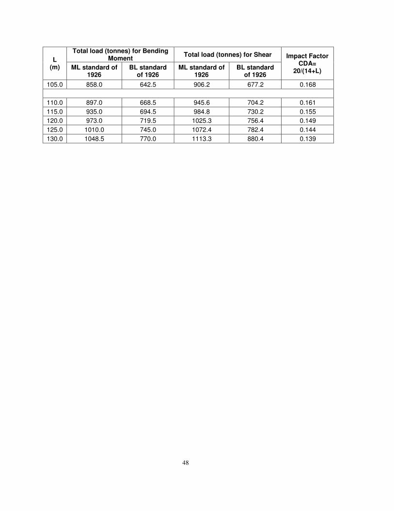
48
L (m)
Total load (tonnes) for Bending Moment
Total load (tonnes) for Shear Impact Factor CDA=
20/(14+L) ML standard of
1926 BL standard
of 1926 ML standard of
1926 BL standard
of 1926
105.0 858.0 642.5 906.2 677.2 0.168
110.0 897.0 668.5 945.6 704.2 0.161
115.0 935.0 694.5 984.8 730.2 0.155
120.0 973.0 719.5 1025.3 756.4 0.149
125.0 1010.0 745.0 1072.4 782.4 0.144
130.0 1048.5 770.0 1113.3 880.4 0.139
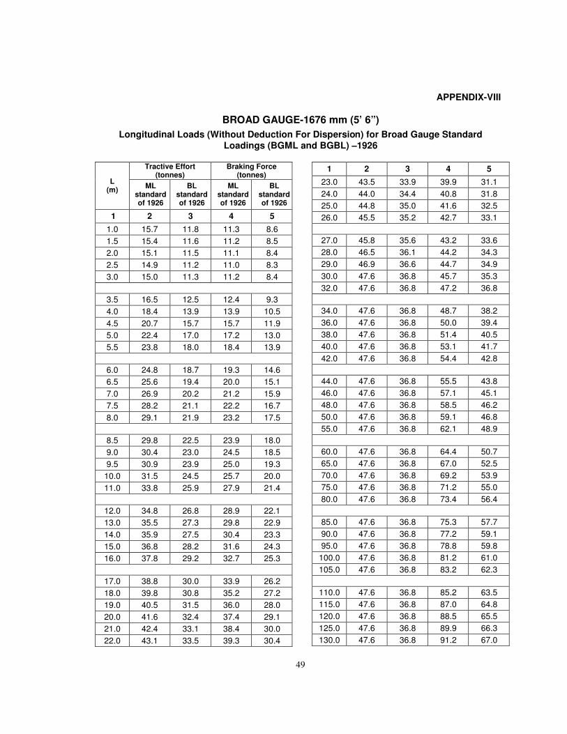
49
APPENDIX-VIII
BROAD GAUGE-1676 mm (5’ 6”)
Longitudinal Loads (Without Deduction For Dispersion) for Broad Gauge Standard
Loadings (BGML and BGBL) –1926
L (m)
Tractive Effort (tonnes)
Braking Force (tonnes)
ML standard of 1926
BL standard of 1926
ML standard of 1926
BL standard of 1926
1 2 3 4 5
1.0 15.7 11.8 11.3 8.6
1.5 15.4 11.6 11.2 8.5
2.0 15.1 11.5 11.1 8.4
2.5 14.9 11.2 11.0 8.3
3.0 15.0 11.3 11.2 8.4
3.5 16.5 12.5 12.4 9.3
4.0 18.4 13.9 13.9 10.5
4.5 20.7 15.7 15.7 11.9
5.0 22.4 17.0 17.2 13.0
5.5 23.8 18.0 18.4 13.9
6.0 24.8 18.7 19.3 14.6
6.5 25.6 19.4 20.0 15.1
7.0 26.9 20.2 21.2 15.9
7.5 28.2 21.1 22.2 16.7
8.0 29.1 21.9 23.2 17.5
8.5 29.8 22.5 23.9 18.0
9.0 30.4 23.0 24.5 18.5
9.5 30.9 23.9 25.0 19.3
10.0 31.5 24.5 25.7 20.0
11.0 33.8 25.9 27.9 21.4
12.0 34.8 26.8 28.9 22.1
13.0 35.5 27.3 29.8 22.9
14.0 35.9 27.5 30.4 23.3
15.0 36.8 28.2 31.6 24.3
16.0 37.8 29.2 32.7 25.3
17.0 38.8 30.0 33.9 26.2
18.0 39.8 30.8 35.2 27.2
19.0 40.5 31.5 36.0 28.0
20.0 41.6 32.4 37.4 29.1
21.0 42.4 33.1 38.4 30.0
22.0 43.1 33.5 39.3 30.4
1 2 3 4 5
23.0 43.5 33.9 39.9 31.1
24.0 44.0 34.4 40.8 31.8
25.0 44.8 35.0 41.6 32.5
26.0 45.5 35.2 42.7 33.1
27.0 45.8 35.6 43.2 33.6
28.0 46.5 36.1 44.2 34.3
29.0 46.9 36.6 44.7 34.9
30.0 47.6 36.8 45.7 35.3
32.0 47.6 36.8 47.2 36.8
34.0 47.6 36.8 48.7 38.2
36.0 47.6 36.8 50.0 39.4
38.0 47.6 36.8 51.4 40.5
40.0 47.6 36.8 53.1 41.7
42.0 47.6 36.8 54.4 42.8
44.0 47.6 36.8 55.5 43.8
46.0 47.6 36.8 57.1 45.1
48.0 47.6 36.8 58.5 46.2
50.0 47.6 36.8 59.1 46.8
55.0 47.6 36.8 62.1 48.9
60.0 47.6 36.8 64.4 50.7
65.0 47.6 36.8 67.0 52.5
70.0 47.6 36.8 69.2 53.9
75.0 47.6 36.8 71.2 55.0
80.0 47.6 36.8 73.4 56.4
85.0 47.6 36.8 75.3 57.7
90.0 47.6 36.8 77.2 59.1
95.0 47.6 36.8 78.8 59.8
100.0 47.6 36.8 81.2 61.0
105.0 47.6 36.8 83.2 62.3
110.0 47.6 36.8 85.2 63.5
115.0 47.6 36.8 87.0 64.8
120.0 47.6 36.8 88.5 65.5
125.0 47.6 36.8 89.9 66.3
130.0 47.6 36.8 91.2 67.0
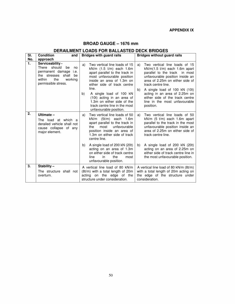
50
APPENDIX IX
BROAD GAUGE – 1676 mm
DERAILMENT LOADS FOR BALLASTED DECK BRIDGES Sl. No.
Condition and approach
Bridges with guard rails Bridges without guard rails
1. Serviceability - There should be no permanent damage i.e. the stresses shall be within the working permissible stress.
a) Two vertical line loads of 15kN/m (1.5 t/m) each 1.6mapart parallel to the track inmost unfavourable positioninside an area of 1.3m oneither side of track centreline.
b) A single load of 100 kN(10t) acting in an area of1.3m on either side of thetrack centre line in the mostunfavourable position.
a) Two vertical line loads of 15kN/m(1.5 t/m) each 1.6m apartparallel to the track in mostunfavourable position inside anarea of 2.25m on either side oftrack centre line.
b) A single load of 100 kN (10t)acting in an area of 2.25m oneither side of the track centreline in the most unfavourableposition.
2. Ultimate –
The load at which a derailed vehicle shall not cause collapse of any major element.
a) Two vertical line loads of 50kN/m (5t/m) each 1.6mapart parallel to the track inthe most unfavourableposition inside an area of1.3m on either side of trackcentre line.
b) A single load of 200 kN (20t)acting on an area of 1.3mon either side of track centreline in the mostunfavourable position.
a) Two vertical line loads of 50kN/m (5 t/m) each 1.6m apartparallel to the track in the mostunfavourable position inside anarea of 2.25m on either side oftrack centre line.
b) A single load of 200 kN (20t)acting on an area of 2.25m oneither side of track centre line inthe most unfavourable position.
3. Stability –
The structure shall not overturn.
A vertical line load of 80 kN/m (8t/m) with a total length of 20m acting on the edge of the structure under consideration.
A vertical line load of 80 kN/m (8t/m) with a total length of 20m acting on the edge of the structure under consideration.
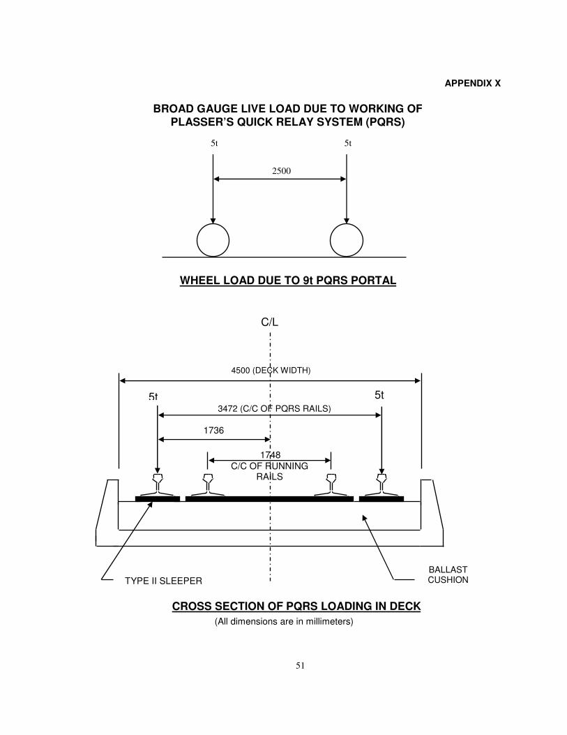
51
APPENDIX X
CROSS SECTION OF PQRS LOADING IN DECK
(All dimensions are in millimeters)
BROAD GAUGE LIVE LOAD DUE TO WORKING OF PLASSER’S QUICK RELAY SYSTEM (PQRS)
WHEEL LOAD DUE TO 9t PQRS PORTAL
2500
5t 5t
C/L
1748
5t 3472 (C/C OF PQRS RAILS)
BALLAST CUSHION
4500 (DECK WIDTH)
1736
TYPE II SLEEPER
C/C OF RUNNING RAILS
5t
5t 5t
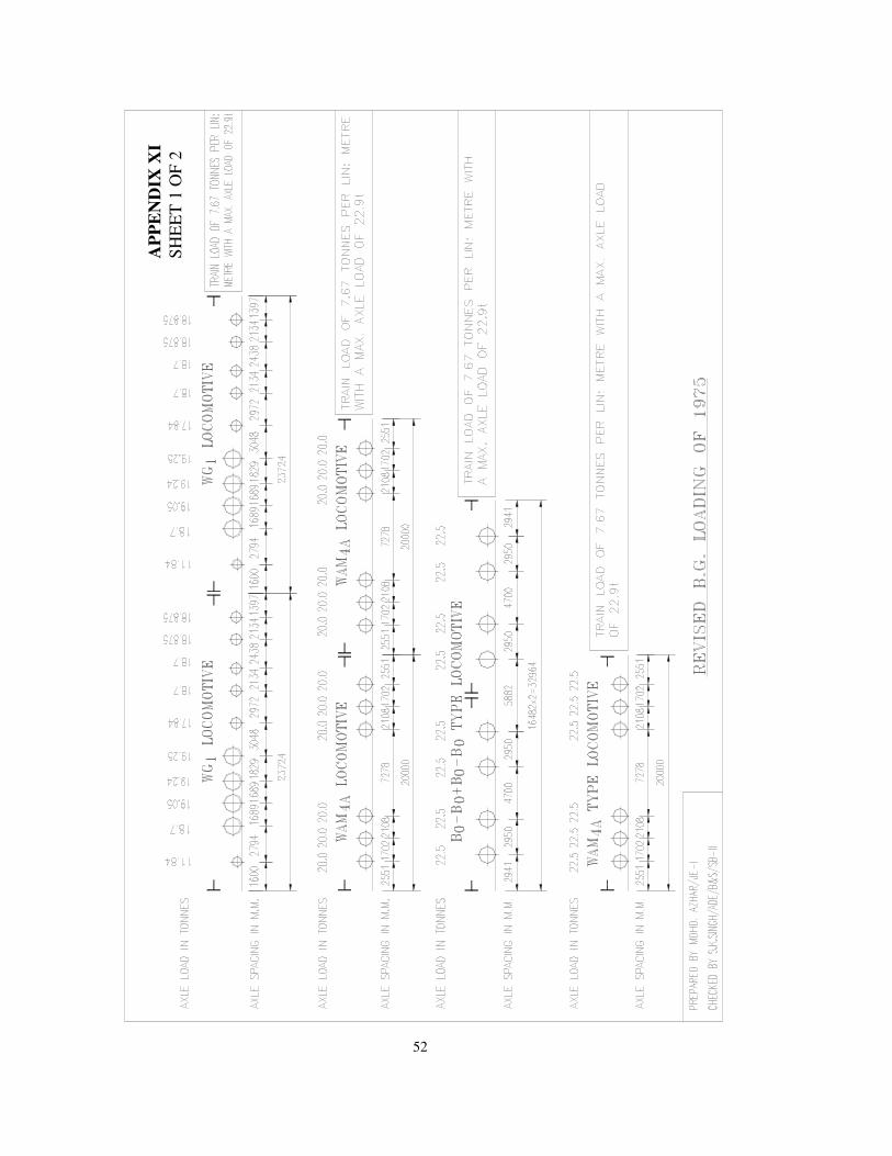
52
AP
PE
ND
IX X
I
SH
EE
T 1
OF
2
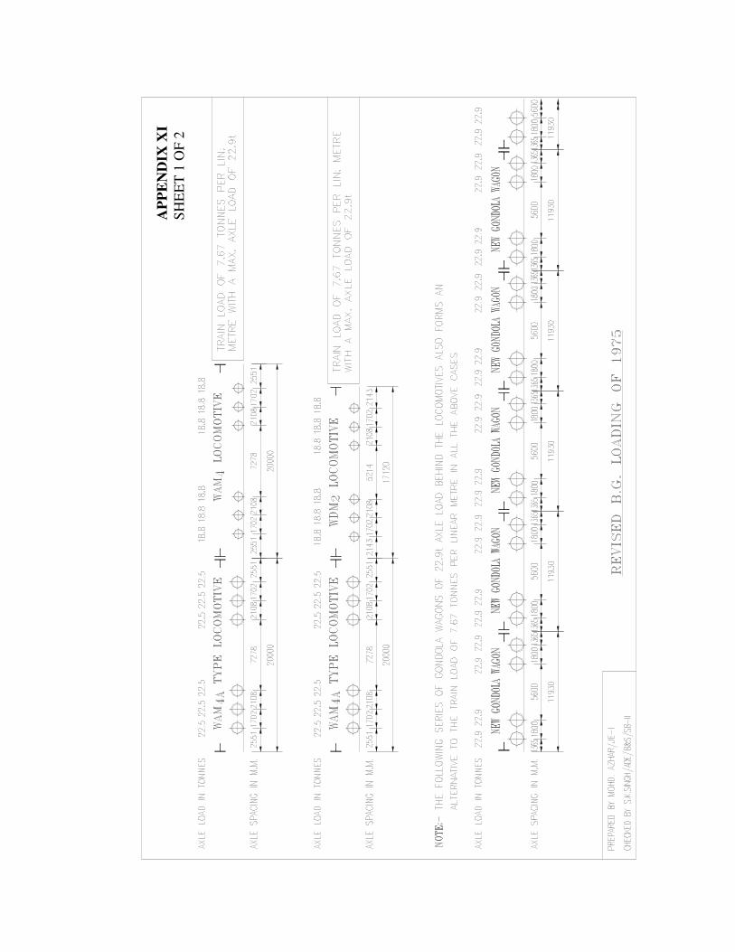
53
AP
PE
ND
IX X
I
SH
EE
T 1
OF
2
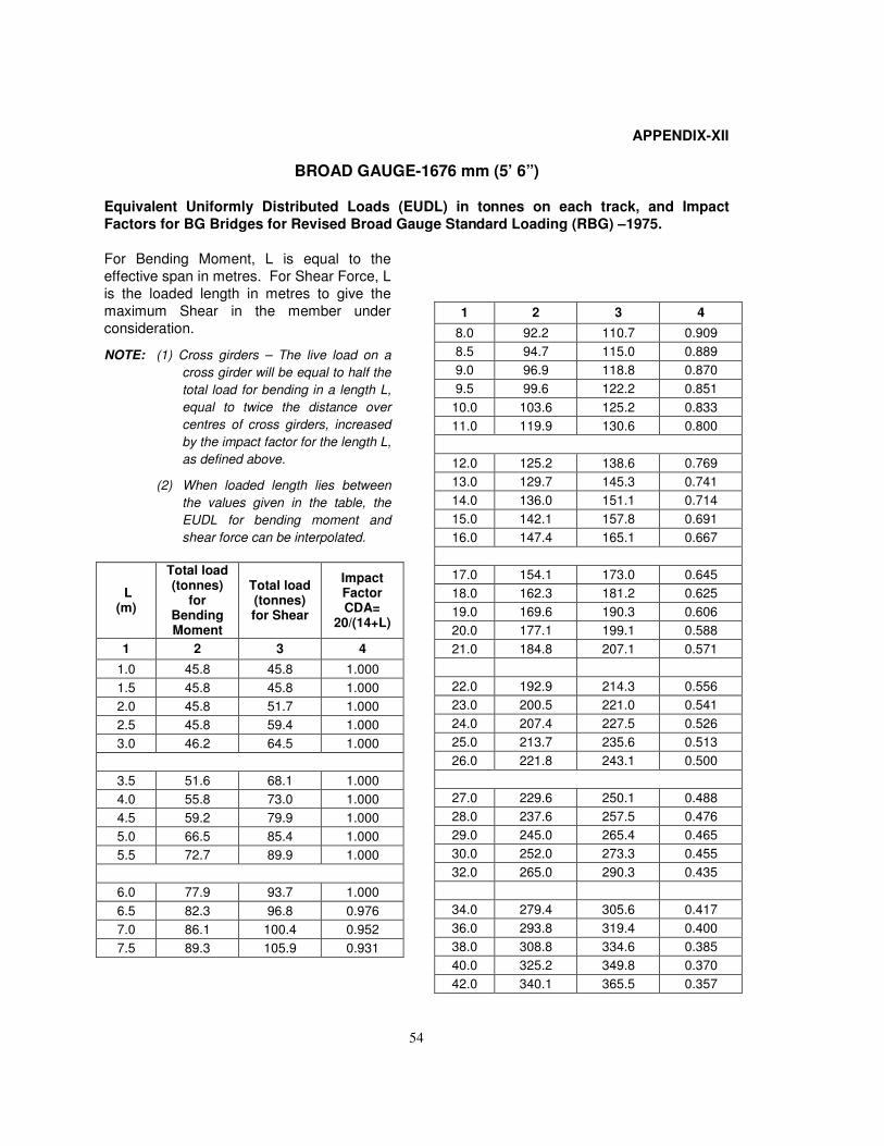
54
APPENDIX-XII
BROAD GAUGE-1676 mm (5’ 6”)
Equivalent Uniformly Distributed Loads (EUDL) in tonnes on each track, and Impact
Factors for BG Bridges for Revised Broad Gauge Standard Loading (RBG) –1975.
For Bending Moment, L is equal to the
effective span in metres. For Shear Force, L
is the loaded length in metres to give the
maximum Shear in the member under
consideration.
NOTE: (1) Cross girders – The live load on a
cross girder will be equal to half the
total load for bending in a length L,
equal to twice the distance over
centres of cross girders, increased
by the impact factor for the length L,
as defined above.
(2) When loaded length lies between
the values given in the table, the
EUDL for bending moment and
shear force can be interpolated.
L (m)
Total load (tonnes)
for Bending Moment
Total load (tonnes) for Shear
Impact Factor CDA=
20/(14+L)
1 2 3 4
1.0 45.8 45.8 1.000
1.5 45.8 45.8 1.000
2.0 45.8 51.7 1.000
2.5 45.8 59.4 1.000
3.0 46.2 64.5 1.000
3.5 51.6 68.1 1.000
4.0 55.8 73.0 1.000
4.5 59.2 79.9 1.000
5.0 66.5 85.4 1.000
5.5 72.7 89.9 1.000
6.0 77.9 93.7 1.000
6.5 82.3 96.8 0.976
7.0 86.1 100.4 0.952
7.5 89.3 105.9 0.931
1 2 3 4
8.0 92.2 110.7 0.909
8.5 94.7 115.0 0.889
9.0 96.9 118.8 0.870
9.5 99.6 122.2 0.851
10.0 103.6 125.2 0.833
11.0 119.9 130.6 0.800
12.0 125.2 138.6 0.769
13.0 129.7 145.3 0.741
14.0 136.0 151.1 0.714
15.0 142.1 157.8 0.691
16.0 147.4 165.1 0.667
17.0 154.1 173.0 0.645
18.0 162.3 181.2 0.625
19.0 169.6 190.3 0.606
20.0 177.1 199.1 0.588
21.0 184.8 207.1 0.571
22.0 192.9 214.3 0.556
23.0 200.5 221.0 0.541
24.0 207.4 227.5 0.526
25.0 213.7 235.6 0.513
26.0 221.8 243.1 0.500
27.0 229.6 250.1 0.488
28.0 237.6 257.5 0.476
29.0 245.0 265.4 0.465
30.0 252.0 273.3 0.455
32.0 265.0 290.3 0.435
34.0 279.4 305.6 0.417
36.0 293.8 319.4 0.400
38.0 308.8 334.6 0.385
40.0 325.2 349.8 0.370
42.0 340.1 365.5 0.357
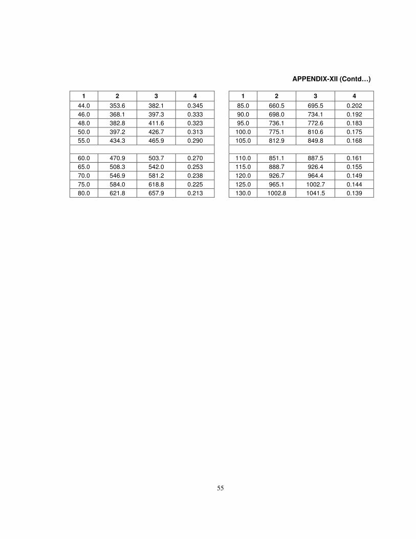
55
APPENDIX-XII (Contd…)
1 2 3 4
44.0 353.6 382.1 0.345
46.0 368.1 397.3 0.333
48.0 382.8 411.6 0.323
50.0 397.2 426.7 0.313
55.0 434.3 465.9 0.290
60.0 470.9 503.7 0.270
65.0 508.3 542.0 0.253
70.0 546.9 581.2 0.238
75.0 584.0 618.8 0.225
80.0 621.8 657.9 0.213
1 2 3 4
85.0 660.5 695.5 0.202
90.0 698.0 734.1 0.192
95.0 736.1 772.6 0.183
100.0 775.1 810.6 0.175
105.0 812.9 849.8 0.168
110.0 851.1 887.5 0.161
115.0 888.7 926.4 0.155
120.0 926.7 964.4 0.149
125.0 965.1 1002.7 0.144
130.0 1002.8 1041.5 0.139
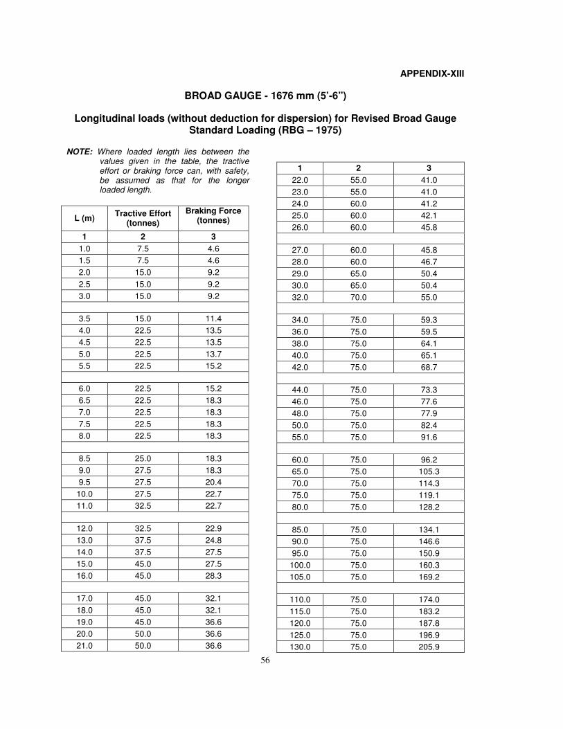
56
APPENDIX-XIII
BROAD GAUGE - 1676 mm (5’-6”)
Longitudinal loads (without deduction for dispersion) for Revised Broad Gauge Standard Loading (RBG – 1975)
NOTE: Where loaded length lies between the values given in the table, the tractive effort or braking force can, with safety, be assumed as that for the longer loaded length.
L (m) Tractive Effort
(tonnes)
Braking Force (tonnes)
1 2 3
1.0 7.5 4.6
1.5 7.5 4.6
2.0 15.0 9.2
2.5 15.0 9.2
3.0 15.0 9.2
3.5 15.0 11.4
4.0 22.5 13.5
4.5 22.5 13.5
5.0 22.5 13.7
5.5 22.5 15.2
6.0 22.5 15.2
6.5 22.5 18.3
7.0 22.5 18.3
7.5 22.5 18.3
8.0 22.5 18.3
8.5 25.0 18.3
9.0 27.5 18.3
9.5 27.5 20.4
10.0 27.5 22.7
11.0 32.5 22.7
12.0 32.5 22.9
13.0 37.5 24.8
14.0 37.5 27.5
15.0 45.0 27.5
16.0 45.0 28.3
17.0 45.0 32.1
18.0 45.0 32.1
19.0 45.0 36.6
20.0 50.0 36.6
21.0 50.0 36.6
1 2 3
22.0 55.0 41.0
23.0 55.0 41.0
24.0 60.0 41.2
25.0 60.0 42.1
26.0 60.0 45.8
27.0 60.0 45.8
28.0 60.0 46.7
29.0 65.0 50.4
30.0 65.0 50.4
32.0 70.0 55.0
34.0 75.0 59.3
36.0 75.0 59.5
38.0 75.0 64.1
40.0 75.0 65.1
42.0 75.0 68.7
44.0 75.0 73.3
46.0 75.0 77.6
48.0 75.0 77.9
50.0 75.0 82.4
55.0 75.0 91.6
60.0 75.0 96.2
65.0 75.0 105.3
70.0 75.0 114.3
75.0 75.0 119.1
80.0 75.0 128.2
85.0 75.0 134.1
90.0 75.0 146.6
95.0 75.0 150.9
100.0 75.0 160.3
105.0 75.0 169.2
110.0 75.0 174.0
115.0 75.0 183.2
120.0 75.0 187.8
125.0 75.0 196.9
130.0 75.0 205.9
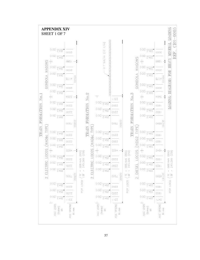
57
APPENDIX XIV
SHEET 1 OF 7
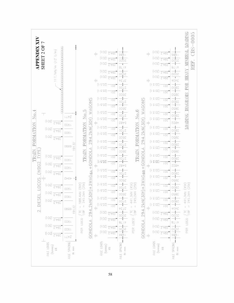
58
AP
PE
ND
IX X
IV
SH
EE
T 2
OF
7
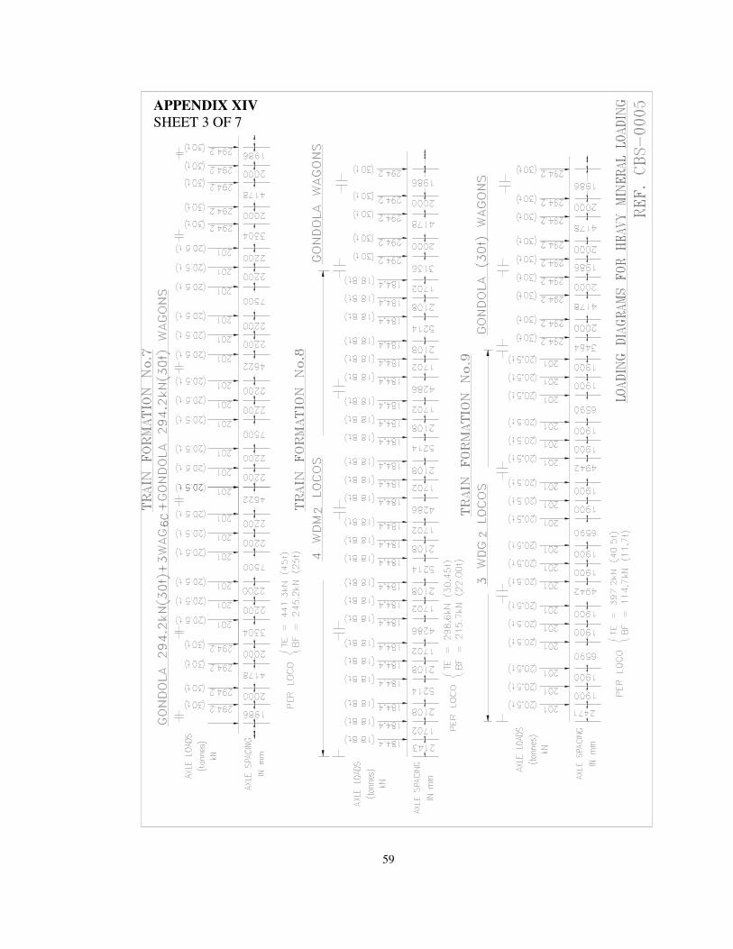
59
APPENDIX XIV
SHEET 3 OF 7
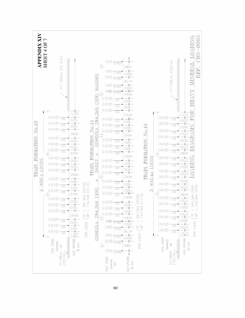
60
AP
PE
ND
IX X
IV
SH
EE
T 4
OF
7
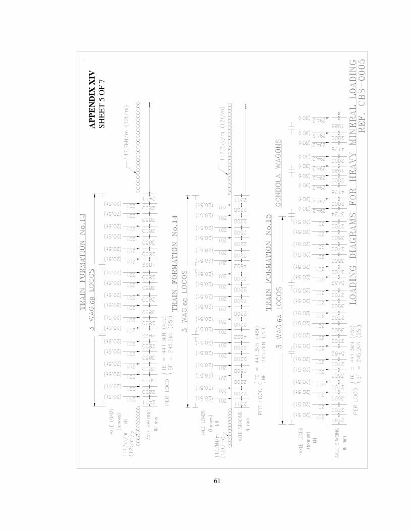
61
AP
PE
ND
IX X
IV
SH
EE
T 5
OF
7
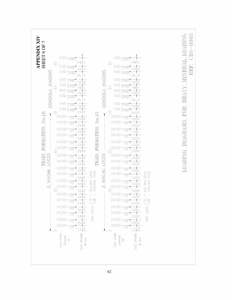
62
AP
PE
ND
IX X
IV
SH
EE
T 6
OF
7
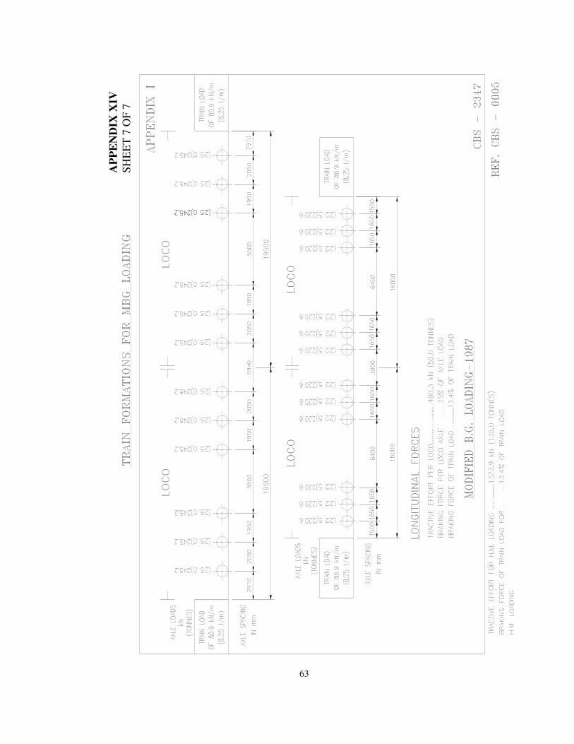
63
AP
PE
ND
IX X
IV
SH
EE
T 7
OF
7
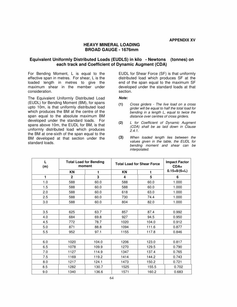
64
APPENDIX XV
HEAVY MINERAL LOADING BROAD GAUGE - 1676mm
Equivalent Uniformly Distributed Loads (EUDLS) in kilo - Newtons (tonnes) on
each track and Coefficient of Dynamic Augment (CDA)
For Bending Moment, L is equal to the effective span in metres. For shear, L is the loaded length in metres to give the maximum shear in the member under consideration.
The Equivalent Uniformly Distributed Load (EUDL) for Bending Moment (BM), for spans upto 10m, is that uniformly distributed load which produces the BM at the centre of the span equal to the absolute maximum BM developed under the standard loads. For spans above 10m, the EUDL for BM, is that uniformly distributed load which produces the BM at one-sixth of the span equal to the BM developed at that section under the standard loads.
EUDL for Shear Force (SF) is that uniformly distributed load which produces SF at the end of the span equal to the maximum SF developed under the standard loads at that section.
Note:
(1) Cross girders - The live load on a cross girder will be equal to half the total load for bending in a length L, equal to twice the distance over centres of cross girders.
(2) L for Coefficient of Dynamic Augment (CDA) shall be as laid down in Clause 2.4.1.
(3) When loaded length lies between the values given in the table, the EUDL for bending moment and shear can be interpolated.
L
(m)
Total Load for Bending moment
Total Load for Shear Force Impact Factor
CDA=
0.15+8/(6+L) KN t KN t
1 2 3 4 5 6
1.0 588 60.0 588 60.0 1.000
1.5 588 60.0 588 60.0 1.000
2.0 588 60.0 618 63.0 1.000
2.5 588 60.0 730 74.4 1.000
3.0 588 60.0 804 82.0 1.000
3.5 625 63.7 857 87.4 0.992
4.0 684 69.8 927 94.5 0.950
4.5 772 78.7 1020 104.0 0.912
5.0 871 88.8 1094 111.6 0.877
5.5 952 97.1 1155 117.8 0.846
6.0 1020 104.0 1206 123.0 0.817
6.5 1078 109.9 1270 129.5 0.790
7.0 1127 114.9 1347 137.4 0.765
7.5 1169 119.2 1414 144.2 0.743
8.0 1217 124.1 1473 150.2 0.721
8.5 1282 130.7 1525 155.5 0.702
9.0 1340 136.6 1571 160.2 0.683
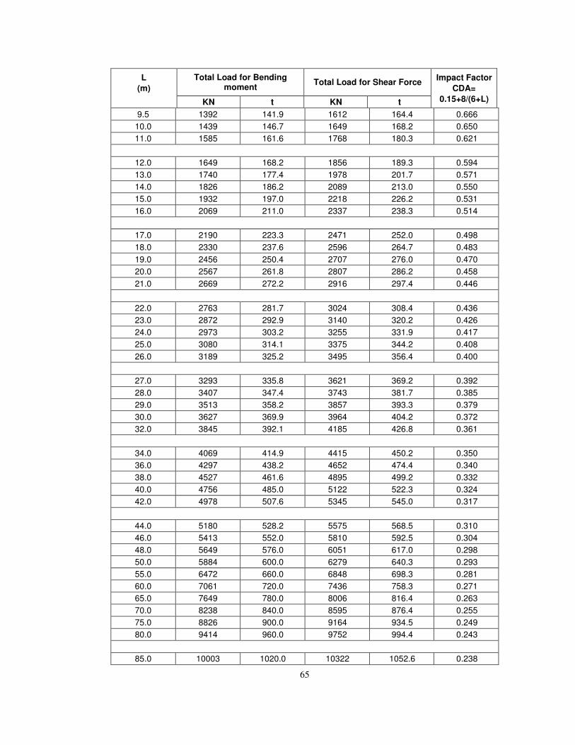
65
L
(m)
Total Load for Bending moment
Total Load for Shear Force Impact Factor
CDA=
0.15+8/(6+L) KN t KN t
9.5 1392 141.9 1612 164.4 0.666
10.0 1439 146.7 1649 168.2 0.650
11.0 1585 161.6 1768 180.3 0.621
12.0 1649 168.2 1856 189.3 0.594
13.0 1740 177.4 1978 201.7 0.571
14.0 1826 186.2 2089 213.0 0.550
15.0 1932 197.0 2218 226.2 0.531
16.0 2069 211.0 2337 238.3 0.514
17.0 2190 223.3 2471 252.0 0.498
18.0 2330 237.6 2596 264.7 0.483
19.0 2456 250.4 2707 276.0 0.470
20.0 2567 261.8 2807 286.2 0.458
21.0 2669 272.2 2916 297.4 0.446
22.0 2763 281.7 3024 308.4 0.436
23.0 2872 292.9 3140 320.2 0.426
24.0 2973 303.2 3255 331.9 0.417
25.0 3080 314.1 3375 344.2 0.408
26.0 3189 325.2 3495 356.4 0.400
27.0 3293 335.8 3621 369.2 0.392
28.0 3407 347.4 3743 381.7 0.385
29.0 3513 358.2 3857 393.3 0.379
30.0 3627 369.9 3964 404.2 0.372
32.0 3845 392.1 4185 426.8 0.361
34.0 4069 414.9 4415 450.2 0.350
36.0 4297 438.2 4652 474.4 0.340
38.0 4527 461.6 4895 499.2 0.332
40.0 4756 485.0 5122 522.3 0.324
42.0 4978 507.6 5345 545.0 0.317
44.0 5180 528.2 5575 568.5 0.310
46.0 5413 552.0 5810 592.5 0.304
48.0 5649 576.0 6051 617.0 0.298
50.0 5884 600.0 6279 640.3 0.293
55.0 6472 660.0 6848 698.3 0.281
60.0 7061 720.0 7436 758.3 0.271
65.0 7649 780.0 8006 816.4 0.263
70.0 8238 840.0 8595 876.4 0.255
75.0 8826 900.0 9164 934.5 0.249
80.0 9414 960.0 9752 994.4 0.243
85.0 10003 1020.0 10322 1052.6 0.238
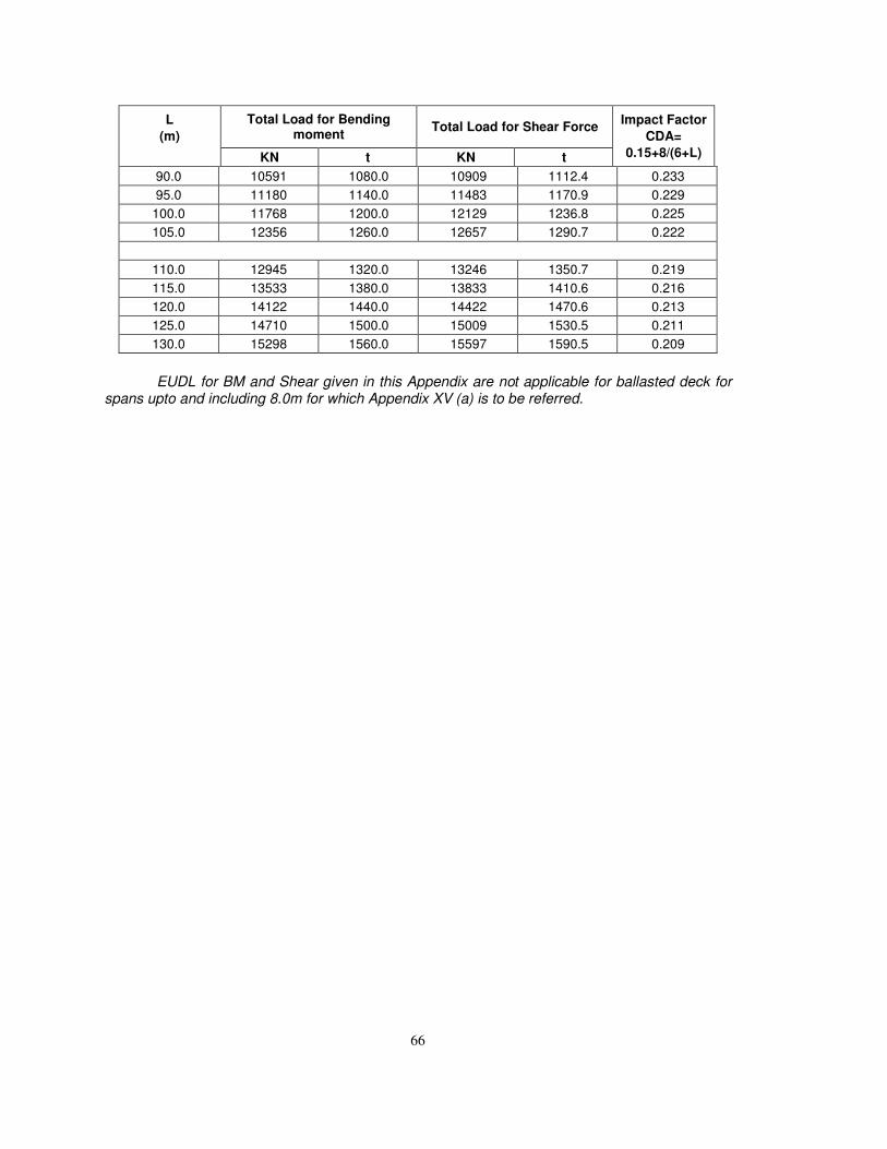
66
L
(m)
Total Load for Bending moment
Total Load for Shear Force Impact Factor
CDA=
0.15+8/(6+L) KN t KN t
90.0 10591 1080.0 10909 1112.4 0.233
95.0 11180 1140.0 11483 1170.9 0.229
100.0 11768 1200.0 12129 1236.8 0.225
105.0 12356 1260.0 12657 1290.7 0.222
110.0 12945 1320.0 13246 1350.7 0.219
115.0 13533 1380.0 13833 1410.6 0.216
120.0 14122 1440.0 14422 1470.6 0.213
125.0 14710 1500.0 15009 1530.5 0.211
130.0 15298 1560.0 15597 1590.5 0.209
EUDL for BM and Shear given in this Appendix are not applicable for ballasted deck for spans upto and including 8.0m for which Appendix XV (a) is to be referred.
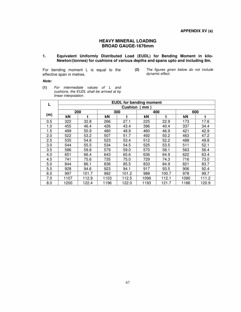
67
APPENDIX XV (a)
HEAVY MINERAL LOADING BROAD GAUGE-1676mm
1. Equivalent Uniformly Distributed Load (EUDL) for Bending Moment in kilo-Newton/(tonnes) for cushions of various depths and spans upto and including 8m.
For bending moment L is equal to the effective span in metres.
Note:
(1) For intermediate values of L and cushions, the EUDL shall be arrived at by linear interpolation.
(2) The figures given below do not include dynamic effect.
L
(m)
EUDL for bending moment
Cushion ( mm )
200 300 400 600
kN t kN t kN t kN t
0.5 322 32.8 266 27.1 225 22.9 173 17.6
1.0 455 46.4 426 43.4 396 40.4 337 34.4
1.5 499 50.9 480 48.9 460 46.9 421 42.9
2.0 522 53.2 507 51.7 492 50.2 463 47.2
2.5 535 54.6 523 53.4 512 52.2 488 49.8
3.0 544 55.5 534 54.5 525 53.5 511 52.1
3.5 586 59.8 579 59.0 570 58.1 563 56.4
4.0 651 66.4 643 65.6 636 64.9 622 63.4
4.5 741 75.6 735 75.0 729 74.3 716 73.0
5.0 844 86.1 838 85.5 833 84.9 821 83.7
5.5 928 94.6 923 94.1 917 93.5 906 92.4
6.0 997 101.7 992 101.2 988 100.7 978 99.7
7.0 1107 112.9 1103 112.5 1099 112.1 1090 111.2
8.0 1200 122.4 1196 122.0 1193 121.7 1186 120.9
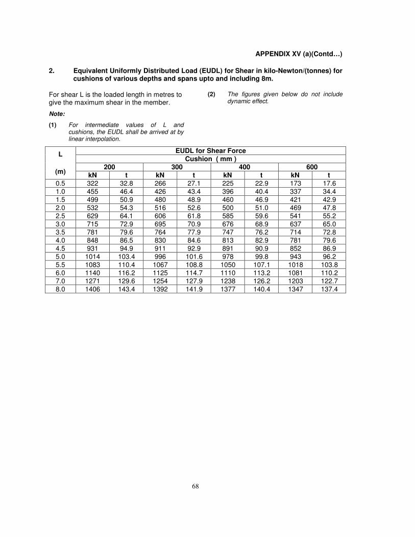
68
APPENDIX XV (a)(Contd…)
2. Equivalent Uniformly Distributed Load (EUDL) for Shear in kilo-Newton/(tonnes) forcushions of various depths and spans upto and including 8m.
For shear L is the loaded length in metres to give the maximum shear in the member.
Note:
(1) For intermediate values of L andcushions, the EUDL shall be arrived at bylinear interpolation.
(2) The figures given below do not includedynamic effect.
L
(m)
EUDL for Shear Force
Cushion ( mm )
200 300 400 600
kN t kN t kN t kN t
0.5 322 32.8 266 27.1 225 22.9 173 17.6
1.0 455 46.4 426 43.4 396 40.4 337 34.4
1.5 499 50.9 480 48.9 460 46.9 421 42.9
2.0 532 54.3 516 52.6 500 51.0 469 47.8
2.5 629 64.1 606 61.8 585 59.6 541 55.2
3.0 715 72.9 695 70.9 676 68.9 637 65.0
3.5 781 79.6 764 77.9 747 76.2 714 72.8
4.0 848 86.5 830 84.6 813 82.9 781 79.6
4.5 931 94.9 911 92.9 891 90.9 852 86.9
5.0 1014 103.4 996 101.6 978 99.8 943 96.2
5.5 1083 110.4 1067 108.8 1050 107.1 1018 103.8
6.0 1140 116.2 1125 114.7 1110 113.2 1081 110.2
7.0 1271 129.6 1254 127.9 1238 126.2 1203 122.7
8.0 1406 143.4 1392 141.9 1377 140.4 1347 137.4
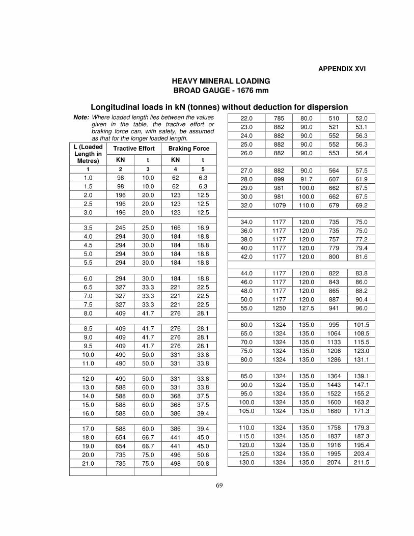
69
APPENDIX XVI
HEAVY MINERAL LOADING
BROAD GAUGE - 1676 mm
Longitudinal loads in kN (tonnes) without deduction for dispersion Note: Where loaded length lies between the values
given in the table, the tractive effort or braking force can, with safety, be assumed as that for the longer loaded length.
L (Loaded Length in Metres)
Tractive Effort Braking Force
KN t KN t
1 2 3 4 5
1.0 98 10.0 62 6.3
1.5 98 10.0 62 6.3
2.0 196 20.0 123 12.5
2.5 196 20.0 123 12.5
3.0 196 20.0 123 12.5
3.5 245 25.0 166 16.9
4.0 294 30.0 184 18.8
4.5 294 30.0 184 18.8
5.0 294 30.0 184 18.8
5.5 294 30.0 184 18.8
6.0 294 30.0 184 18.8
6.5 327 33.3 221 22.5
7.0 327 33.3 221 22.5
7.5 327 33.3 221 22.5
8.0 409 41.7 276 28.1
8.5 409 41.7 276 28.1
9.0 409 41.7 276 28.1
9.5 409 41.7 276 28.1
10.0 490 50.0 331 33.8
11.0 490 50.0 331 33.8
12.0 490 50.0 331 33.8
13.0 588 60.0 331 33.8
14.0 588 60.0 368 37.5
15.0 588 60.0 368 37.5
16.0 588 60.0 386 39.4
17.0 588 60.0 386 39.4
18.0 654 66.7 441 45.0
19.0 654 66.7 441 45.0
20.0 735 75.0 496 50.6
21.0 735 75.0 498 50.8
22.0 785 80.0 510 52.0
23.0 882 90.0 521 53.1
24.0 882 90.0 552 56.3
25.0 882 90.0 552 56.3
26.0 882 90.0 553 56.4
27.0 882 90.0 564 57.5
28.0 899 91.7 607 61.9
29.0 981 100.0 662 67.5
30.0 981 100.0 662 67.5
32.0 1079 110.0 679 69.2
34.0 1177 120.0 735 75.0
36.0 1177 120.0 735 75.0
38.0 1177 120.0 757 77.2
40.0 1177 120.0 779 79.4
42.0 1177 120.0 800 81.6
44.0 1177 120.0 822 83.8
46.0 1177 120.0 843 86.0
48.0 1177 120.0 865 88.2
50.0 1177 120.0 887 90.4
55.0 1250 127.5 941 96.0
60.0 1324 135.0 995 101.5
65.0 1324 135.0 1064 108.5
70.0 1324 135.0 1133 115.5
75.0 1324 135.0 1206 123.0
80.0 1324 135.0 1286 131.1
85.0 1324 135.0 1364 139.1
90.0 1324 135.0 1443 147.1
95.0 1324 135.0 1522 155.2
100.0 1324 135.0 1600 163.2
105.0 1324 135.0 1680 171.3
110.0 1324 135.0 1758 179.3
115.0 1324 135.0 1837 187.3
120.0 1324 135.0 1916 195.4
125.0 1324 135.0 1995 203.4
130.0 1324 135.0 2074 211.5
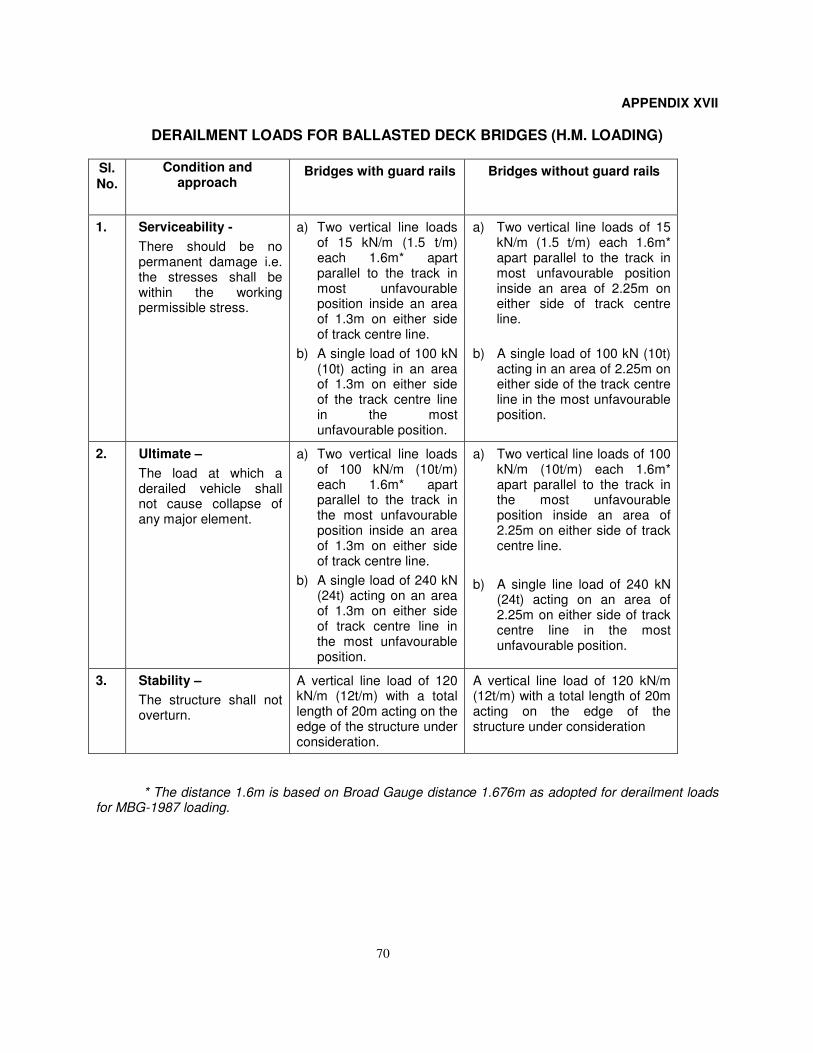
70
APPENDIX XVII
DERAILMENT LOADS FOR BALLASTED DECK BRIDGES (H.M. LOADING)
Sl.
No.
Condition and approach
Bridges with guard rails Bridges without guard rails
1. Serviceability -
There should be no permanent damage i.e. the stresses shall be within the working permissible stress.
a) Two vertical line loads of 15 kN/m (1.5 t/m) each 1.6m* apart parallel to the track in most unfavourable position inside an area of 1.3m on either side of track centre line.
b) A single load of 100 kN (10t) acting in an area of 1.3m on either side of the track centre line in the most unfavourable position.
a) Two vertical line loads of 15 kN/m (1.5 t/m) each 1.6m* apart parallel to the track in most unfavourable position inside an area of 2.25m on either side of track centre line.
b) A single load of 100 kN (10t) acting in an area of 2.25m on either side of the track centre line in the most unfavourable position.
2. Ultimate –
The load at which a derailed vehicle shall not cause collapse of any major element.
a) Two vertical line loads of 100 kN/m (10t/m) each 1.6m* apart parallel to the track in the most unfavourable position inside an area of 1.3m on either side of track centre line.
b) A single load of 240 kN (24t) acting on an area of 1.3m on either side of track centre line in the most unfavourable position.
a) Two vertical line loads of 100 kN/m (10t/m) each 1.6m* apart parallel to the track in the most unfavourable position inside an area of 2.25m on either side of track centre line.
b) A single line load of 240 kN (24t) acting on an area of 2.25m on either side of track centre line in the most unfavourable position.
3. Stability –
The structure shall not overturn.
A vertical line load of 120 kN/m (12t/m) with a total length of 20m acting on the edge of the structure under consideration.
A vertical line load of 120 kN/m (12t/m) with a total length of 20m acting on the edge of the structure under consideration
* The distance 1.6m is based on Broad Gauge distance 1.676m as adopted for derailment loads for MBG-1987 loading.
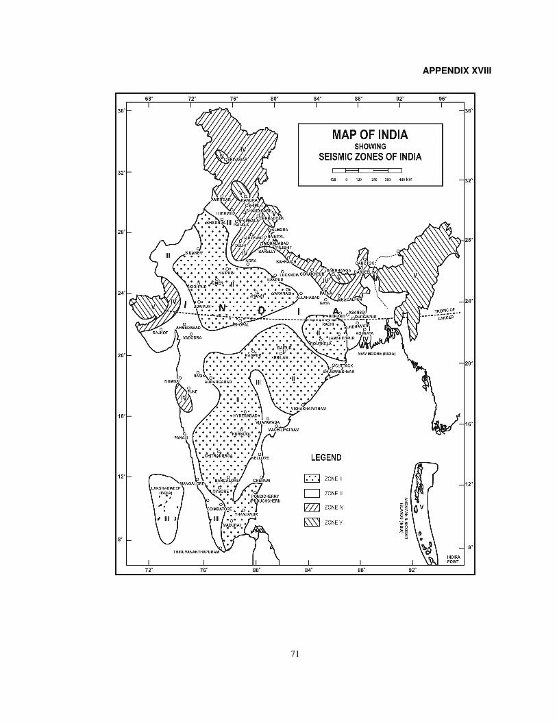
71
APPENDIX XVIII
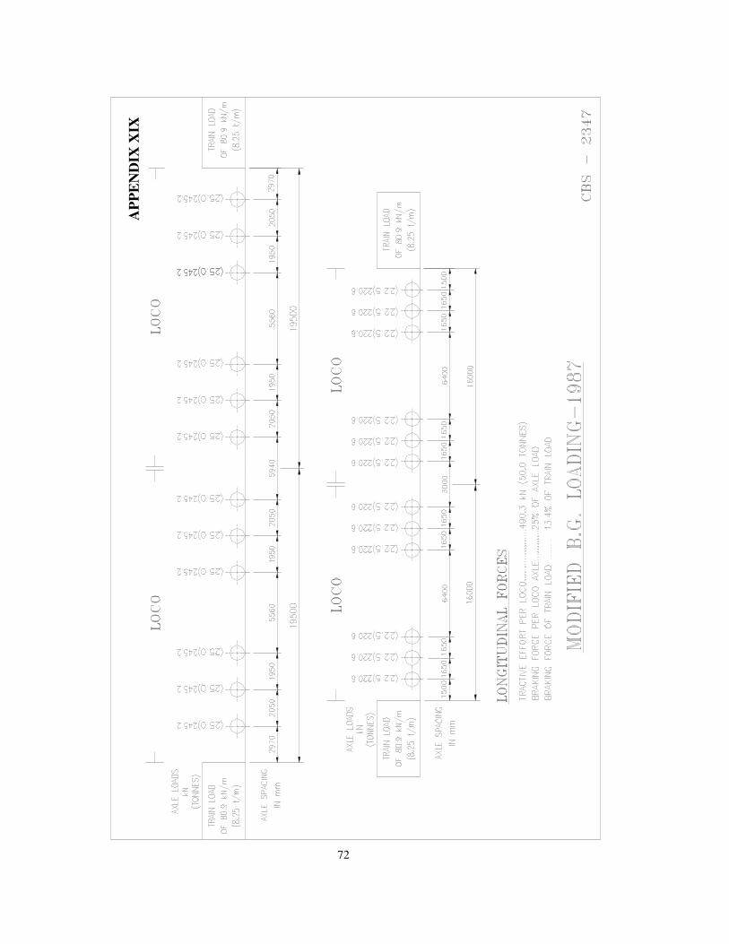
72
AP
PE
ND
IX X
IX
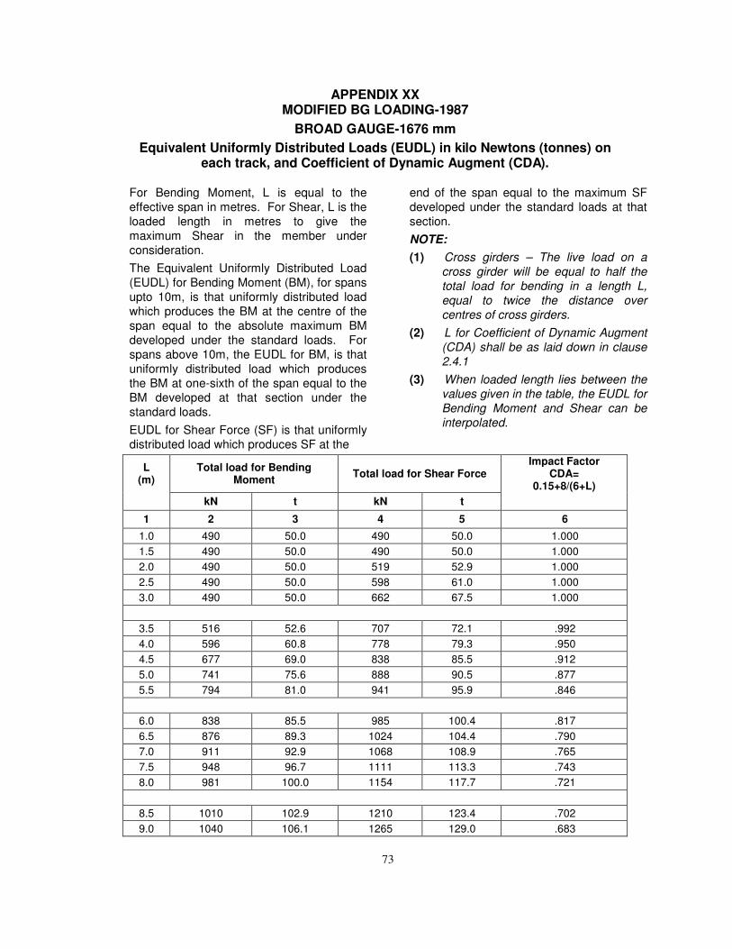
73
APPENDIX XX MODIFIED BG LOADING-1987
BROAD GAUGE-1676 mm
Equivalent Uniformly Distributed Loads (EUDL) in kilo Newtons (tonnes) on each track, and Coefficient of Dynamic Augment (CDA).
For Bending Moment, L is equal to the
effective span in metres. For Shear, L is the
loaded length in metres to give the
maximum Shear in the member under
consideration.
The Equivalent Uniformly Distributed Load
(EUDL) for Bending Moment (BM), for spans
upto 10m, is that uniformly distributed load
which produces the BM at the centre of the
span equal to the absolute maximum BM
developed under the standard loads. For
spans above 10m, the EUDL for BM, is that
uniformly distributed load which produces
the BM at one-sixth of the span equal to the
BM developed at that section under the
standard loads.
EUDL for Shear Force (SF) is that uniformly
distributed load which produces SF at the
end of the span equal to the maximum SF
developed under the standard loads at that
section.
NOTE:
(1) Cross girders – The live load on a
cross girder will be equal to half the
total load for bending in a length L,
equal to twice the distance over
centres of cross girders.
(2) L for Coefficient of Dynamic Augment
(CDA) shall be as laid down in clause
2.4.1
(3) When loaded length lies between the
values given in the table, the EUDL for
Bending Moment and Shear can be
interpolated.
L (m)
Total load for Bending Moment
Total load for Shear Force Impact Factor
CDA= 0.15+8/(6+L)
kN t kN t
1 2 3 4 5 6
1.0 490 50.0 490 50.0 1.000
1.5 490 50.0 490 50.0 1.000
2.0 490 50.0 519 52.9 1.000
2.5 490 50.0 598 61.0 1.000
3.0 490 50.0 662 67.5 1.000
3.5 516 52.6 707 72.1 .992
4.0 596 60.8 778 79.3 .950
4.5 677 69.0 838 85.5 .912
5.0 741 75.6 888 90.5 .877
5.5 794 81.0 941 95.9 .846
6.0 838 85.5 985 100.4 .817
6.5 876 89.3 1024 104.4 .790
7.0 911 92.9 1068 108.9 .765
7.5 948 96.7 1111 113.3 .743
8.0 981 100.0 1154 117.7 .721
8.5 1010 102.9 1210 123.4 .702
9.0 1040 106.1 1265 129.0 .683
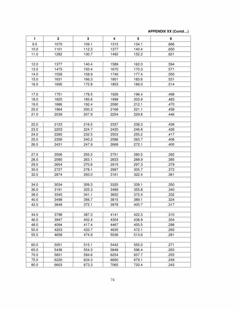
74
APPENDIX XX (Contd…)
1 2 3 4 5 6
9.5 1070 109.1 1315 134.1 .666
10.0 1101 112.3 1377 140.4 .650
11.0 1282 130.7 1492 152.2 .621
12.0 1377 140.4 1589 162.0 .594
13.0 1475 150.4 1670 170.3 .571
14.0 1558 158.9 1740 177.4 .550
15.0 1631 166.3 1801 183.6 .531
16.0 1695 172.8 1853 189.0 .514
17.0 1751 178.5 1926 196.4 .498
18.0 1820 185.6 1999 203.9 .483
19.0 1886 192.4 2080 212.1 .470
20.0 1964 200.3 2168 221.1 .458
21.0 2039 207.9 2254 229.8 .446
22.0 2123 216.5 2337 238.3 .436
23.0 2203 224.7 2420 246.8 .426
24.0 2280 232.5 2503 255.2 .417
25.0 2356 240.2 2586 263.7 .408
26.0 2431 247.9 2668 272.1 .400
27.0 2506 255.5 2751 280.5 .392
28.0 2580 263.1 2833 288.9 .385
29.0 2654 270.6 2915 297.3 .379
30.0 2727 278.1 2997 305.7 .372
32.0 2874 293.0 3161 322.4 .361
34.0 3034 309.3 3325 339.1 .350
36.0 3191 325.3 3489 355.8 .340
38.0 3345 341.1 3652 372.4 .332
40.0 3498 356.7 3815 389.1 .324
42.0 3649 372.1 3978 405.7 .317
44.0 3798 387.3 4141 422.3 .310
46.0 3947 402.4 4304 438.9 .304
48.0 4094 417.4 4467 455.5 .298
50.0 4253 433.7 4630 472.1 .293
55.0 4658 474.9 5036 513.6 .281
60.0 5051 515.1 5442 555.0 .271
65.0 5436 554.3 5848 596.4 .263
70.0 5831 594.6 6254 637.7 .255
75.0 6220 634.3 6660 679.1 .249
80.0 6603 673.3 7065 720.4 .243
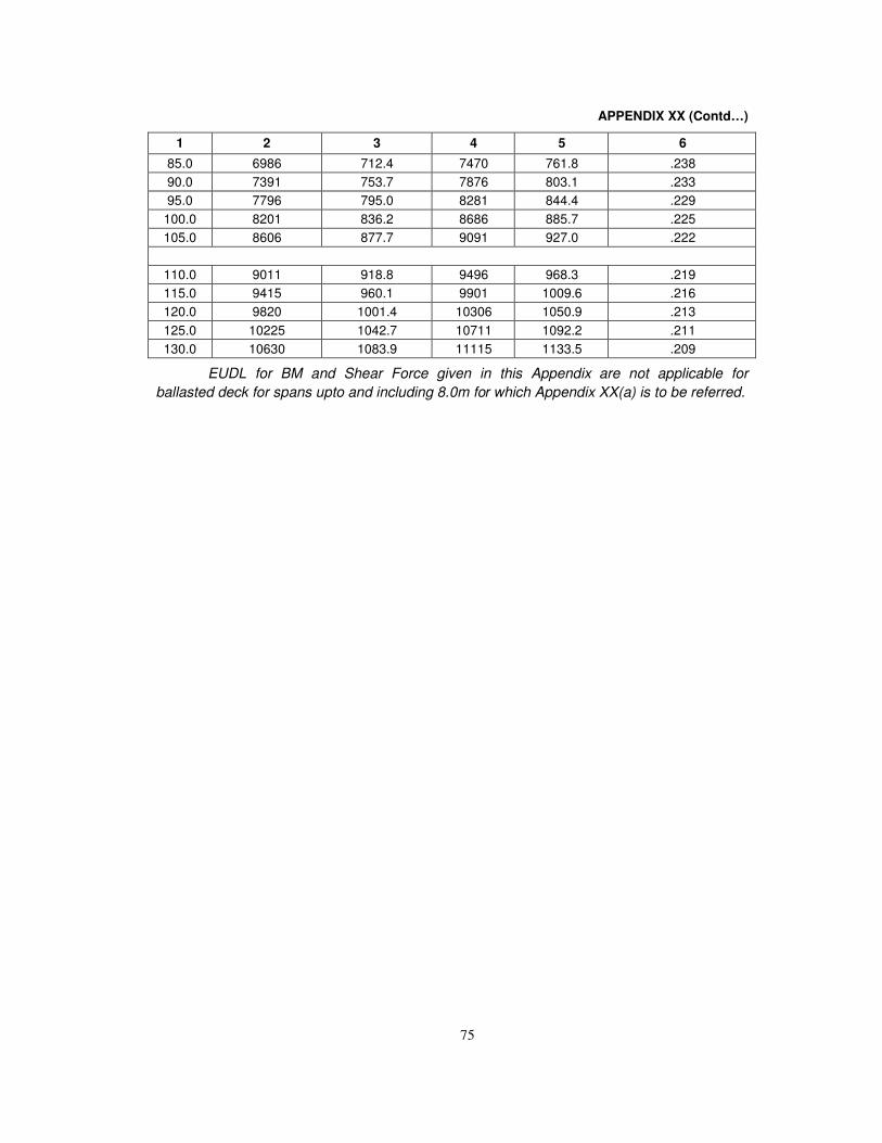
75
APPENDIX XX (Contd…)
1 2 3 4 5 6
85.0 6986 712.4 7470 761.8 .238
90.0 7391 753.7 7876 803.1 .233
95.0 7796 795.0 8281 844.4 .229
100.0 8201 836.2 8686 885.7 .225
105.0 8606 877.7 9091 927.0 .222
110.0 9011 918.8 9496 968.3 .219
115.0 9415 960.1 9901 1009.6 .216
120.0 9820 1001.4 10306 1050.9 .213
125.0 10225 1042.7 10711 1092.2 .211
130.0 10630 1083.9 11115 1133.5 .209
EUDL for BM and Shear Force given in this Appendix are not applicable for
ballasted deck for spans upto and including 8.0m for which Appendix XX(a) is to be referred.
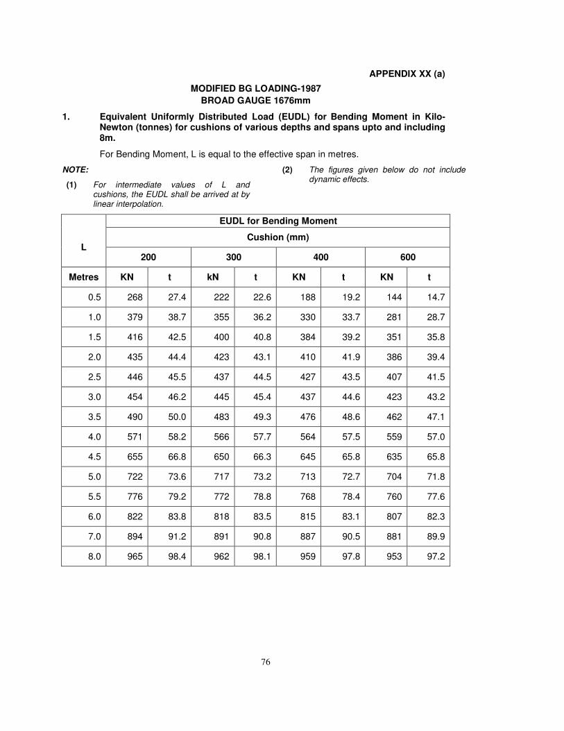
76
APPENDIX XX (a)
MODIFIED BG LOADING-1987
BROAD GAUGE 1676mm
1. Equivalent Uniformly Distributed Load (EUDL) for Bending Moment in Kilo-Newton (tonnes) for cushions of various depths and spans upto and including8m.
For Bending Moment, L is equal to the effective span in metres.
NOTE:
(1) For intermediate values of L andcushions, the EUDL shall be arrived at bylinear interpolation.
(2) The figures given below do not includedynamic effects.
EUDL for Bending Moment
L Cushion (mm)
200 300 400 600
Metres KN t kN t KN t KN t
0.5 268 27.4 222 22.6 188 19.2 144 14.7
1.0 379 38.7 355 36.2 330 33.7 281 28.7
1.5 416 42.5 400 40.8 384 39.2 351 35.8
2.0 435 44.4 423 43.1 410 41.9 386 39.4
2.5 446 45.5 437 44.5 427 43.5 407 41.5
3.0 454 46.2 445 45.4 437 44.6 423 43.2
3.5 490 50.0 483 49.3 476 48.6 462 47.1
4.0 571 58.2 566 57.7 564 57.5 559 57.0
4.5 655 66.8 650 66.3 645 65.8 635 65.8
5.0 722 73.6 717 73.2 713 72.7 704 71.8
5.5 776 79.2 772 78.8 768 78.4 760 77.6
6.0 822 83.8 818 83.5 815 83.1 807 82.3
7.0 894 91.2 891 90.8 887 90.5 881 89.9
8.0 965 98.4 962 98.1 959 97.8 953 97.2
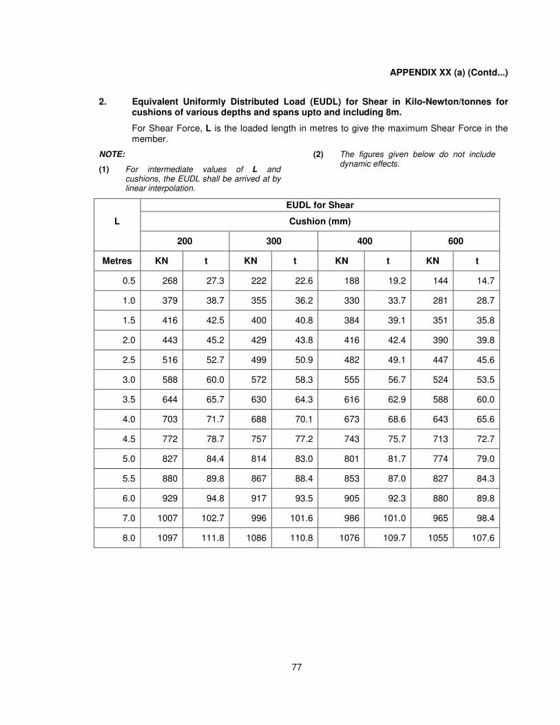
77
APPENDIX XX (a) (Contd...)
2. Equivalent Uniformly Distributed Load (EUDL) for Shear in Kilo-Newton/tonnes forcushions of various depths and spans upto and including 8m.
For Shear Force, L is the loaded length in metres to give the maximum Shear Force in themember.
NOTE:
(1) For intermediate values of L andcushions, the EUDL shall be arrived at bylinear interpolation.
(2) The figures given below do not includedynamic effects.
EUDL for Shear
L Cushion (mm)
200 300 400 600
Metres KN t KN t KN t KN t
0.5 268 27.3 222 22.6 188 19.2 144 14.7
1.0 379 38.7 355 36.2 330 33.7 281 28.7
1.5 416 42.5 400 40.8 384 39.1 351 35.8
2.0 443 45.2 429 43.8 416 42.4 390 39.8
2.5 516 52.7 499 50.9 482 49.1 447 45.6
3.0 588 60.0 572 58.3 555 56.7 524 53.5
3.5 644 65.7 630 64.3 616 62.9 588 60.0
4.0 703 71.7 688 70.1 673 68.6 643 65.6
4.5 772 78.7 757 77.2 743 75.7 713 72.7
5.0 827 84.4 814 83.0 801 81.7 774 79.0
5.5 880 89.8 867 88.4 853 87.0 827 84.3
6.0 929 94.8 917 93.5 905 92.3 880 89.8
7.0 1007 102.7 996 101.6 986 101.0 965 98.4
8.0 1097 111.8 1086 110.8 1076 109.7 1055 107.6
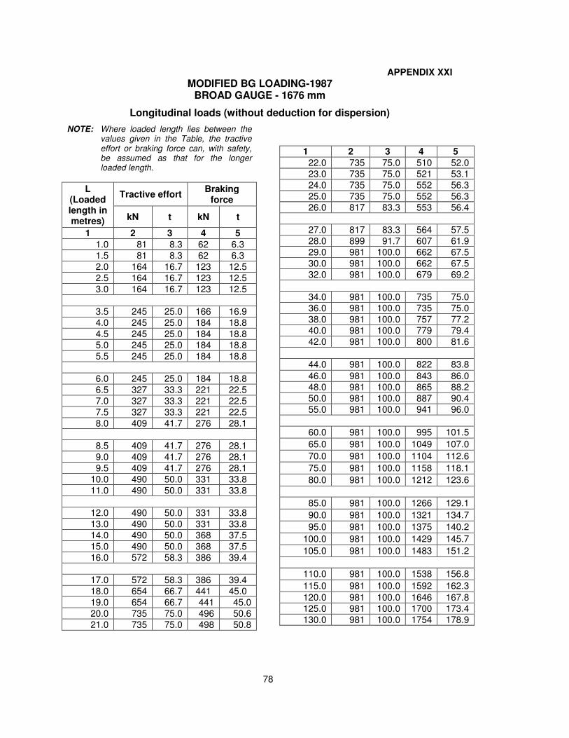
78
APPENDIX XXI
MODIFIED BG LOADING-1987 BROAD GAUGE - 1676 mm
Longitudinal loads (without deduction for dispersion)
NOTE: Where loaded length lies between the values given in the Table, the tractive effort or braking force can, with safety, be assumed as that for the longer loaded length.
L (Loaded length in metres)
Tractive effort Braking
force
kN t kN t
1 2 3 4 5
1.0 81 8.3 62 6.3
1.5 81 8.3 62 6.3
2.0 164 16.7 123 12.5
2.5 164 16.7 123 12.5
3.0 164 16.7 123 12.5
3.5 245 25.0 166 16.9
4.0 245 25.0 184 18.8
4.5 245 25.0 184 18.8
5.0 245 25.0 184 18.8
5.5 245 25.0 184 18.8
6.0 245 25.0 184 18.8
6.5 327 33.3 221 22.5
7.0 327 33.3 221 22.5
7.5 327 33.3 221 22.5
8.0 409 41.7 276 28.1
8.5 409 41.7 276 28.1
9.0 409 41.7 276 28.1
9.5 409 41.7 276 28.1
10.0 490 50.0 331 33.8
11.0 490 50.0 331 33.8
12.0 490 50.0 331 33.8
13.0 490 50.0 331 33.8
14.0 490 50.0 368 37.5
15.0 490 50.0 368 37.5
16.0 572 58.3 386 39.4
17.0 572 58.3 386 39.4
18.0 654 66.7 441 45.0
19.0 654 66.7 441 45.0
20.0 735 75.0 496 50.6
21.0 735 75.0 498 50.8
1 2 3 4 5
22.0 735 75.0 510 52.0
23.0 735 75.0 521 53.1
24.0 735 75.0 552 56.3
25.0 735 75.0 552 56.3
26.0 817 83.3 553 56.4
27.0 817 83.3 564 57.5
28.0 899 91.7 607 61.9
29.0 981 100.0 662 67.5
30.0 981 100.0 662 67.5
32.0 981 100.0 679 69.2
34.0 981 100.0 735 75.0
36.0 981 100.0 735 75.0
38.0 981 100.0 757 77.2
40.0 981 100.0 779 79.4
42.0 981 100.0 800 81.6
44.0 981 100.0 822 83.8
46.0 981 100.0 843 86.0
48.0 981 100.0 865 88.2
50.0 981 100.0 887 90.4
55.0 981 100.0 941 96.0
60.0 981 100.0 995 101.5
65.0 981 100.0 1049 107.0
70.0 981 100.0 1104 112.6
75.0 981 100.0 1158 118.1
80.0 981 100.0 1212 123.6
85.0 981 100.0 1266 129.1
90.0 981 100.0 1321 134.7
95.0 981 100.0 1375 140.2
100.0 981 100.0 1429 145.7
105.0 981 100.0 1483 151.2
110.0 981 100.0 1538 156.8
115.0 981 100.0 1592 162.3
120.0 981 100.0 1646 167.8
125.0 981 100.0 1700 173.4
130.0 981 100.0 1754 178.9
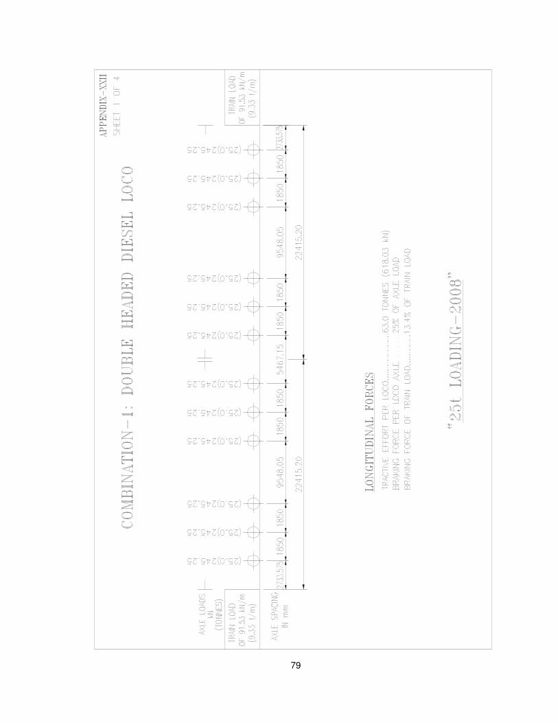
79
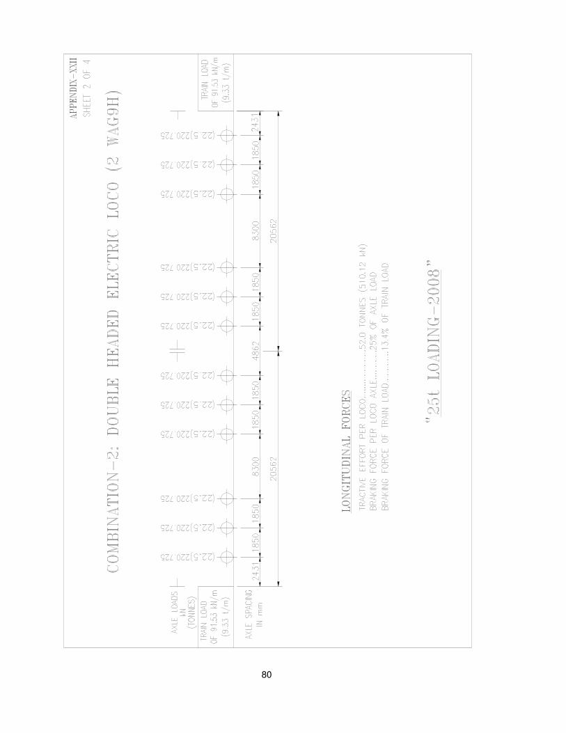
80
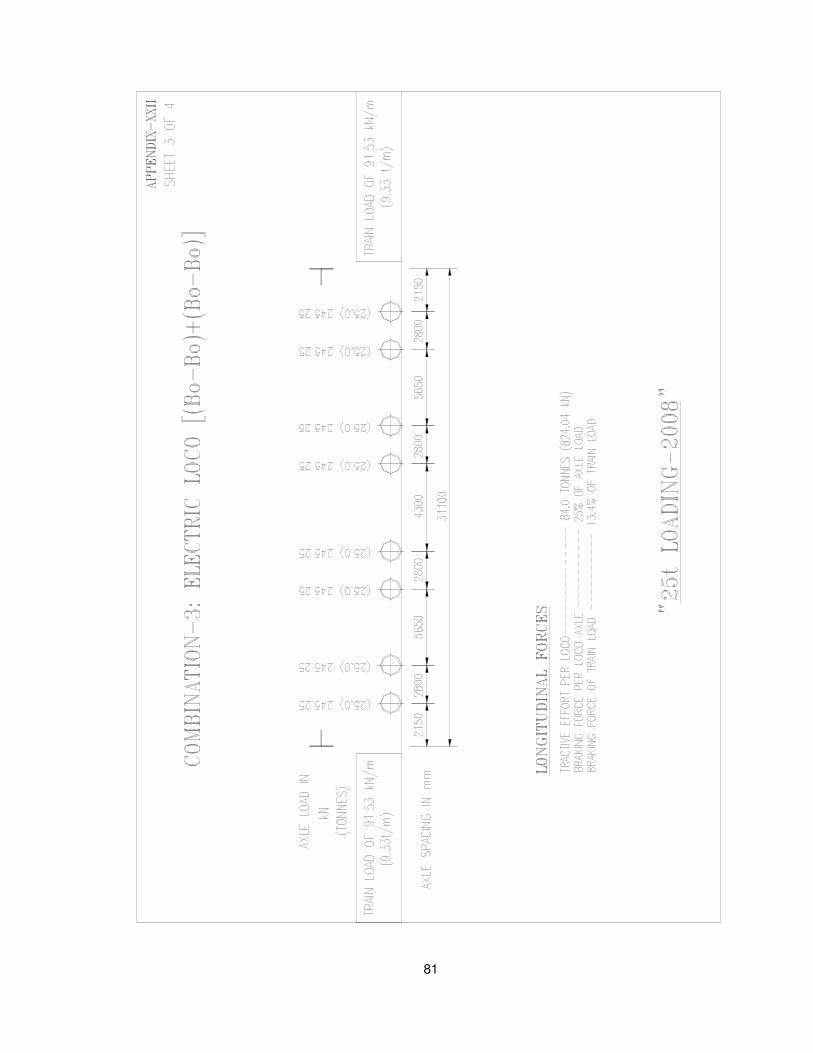
81
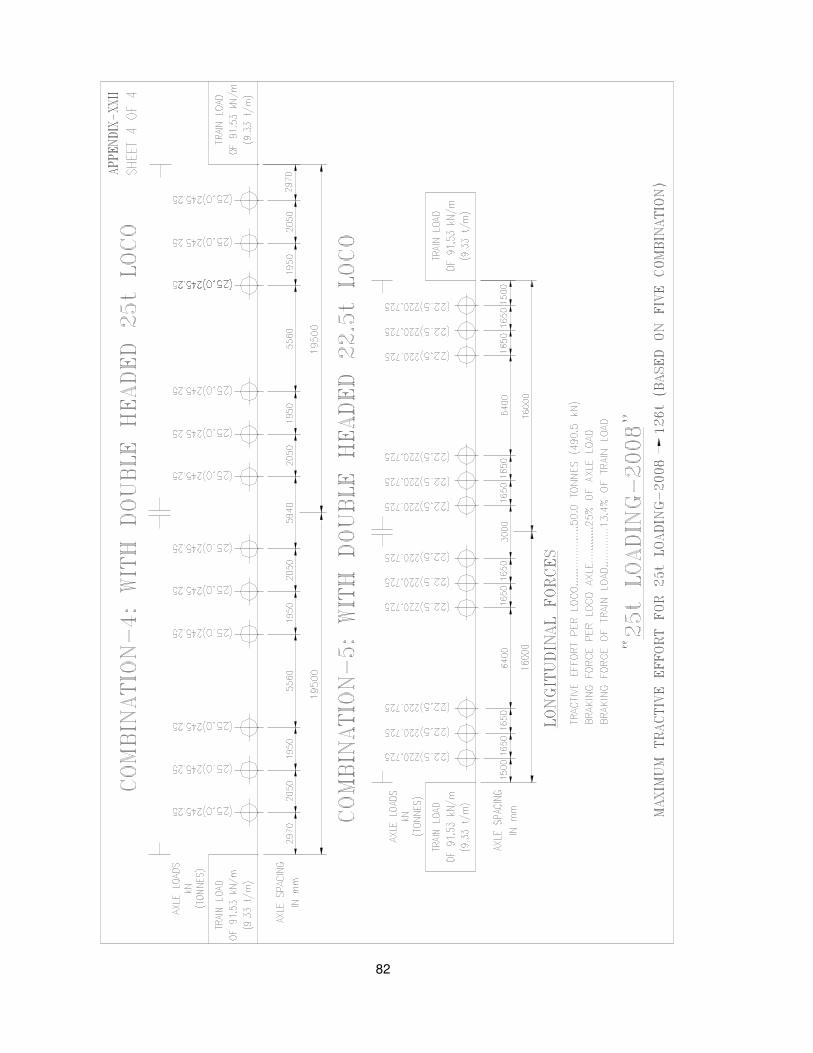
82
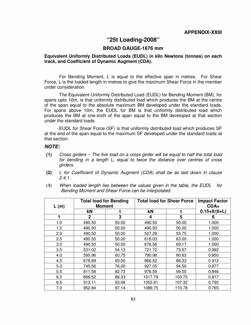
83
APPENDIX-XXIII
“25t Loading-2008”
BROAD GAUGE-1676 mm
Equivalent Uniformly Distributed Loads (EUDL) in kilo Newtons (tonnes) on each track, and Coefficient of Dynamic Augment (CDA).
For Bending Moment, L is equal to the effective span in metres. For Shear Force, L is the loaded length in metres to give the maximum Shear Force in the member under consideration.
The Equivalent Uniformly Distributed Load (EUDL) for Bending Moment (BM), for spans upto 10m, is that uniformly distributed load which produces the BM at the centre of the span equal to the absolute maximum BM developed under the standard loads. For spans above 10m, the EUDL for BM is that uniformly distributed load which produces the BM at one-sixth of the span equal to the BM developed at that section under the standard loads.
EUDL for Shear Force (SF) is that uniformly distributed load which produces SF at the end of the span equal to the maximum SF developed under the standard loads at that section.
NOTE:
(1) Cross girders – The live load on a cross girder will be equal to half the total loadfor bending in a length L, equal to twice the distance over centres of crossgirders.
(2) L for Coefficient of Dynamic Augment (CDA) shall be as laid down in clause2.4.1.
(3) When loaded length lies between the values given in the table, the EUDL forBending Moment and Shear Force can be interpolated.
L (m) Total load for Bending
Moment Total load for Shear Force Impact Factor
CDA= 0.15+8/(6+L) kN t kN t
1 2 3 4 5 6
1.0 490.50 50.00 490.50 50.00 1.000
1.5 490.50 50.00 490.50 50.00 1.000
2.0 490.50 50.00 527.29 53.75 1.000
2.5 490.50 50.00 618.03 63.00 1.000
3.0 490.50 50.00 678.56 69.17 1.000
3.5 531.02 54.13 721.72 73.57 0.992
4.0 595.96 60.75 790.98 80.63 0.950
4.5 676.89 69.00 866.52 88.33 0.912
5.0 745.56 76.00 927.05 94.50 0.877
5.5 811.58 82.73 976.59 99.55 0.846
6.0 866.52 88.33 1017.79 103.75 0.817
6.5 913.11 93.08 1052.81 107.32 0.790
7.0 952.94 97.14 1086.75 110.78 0.765
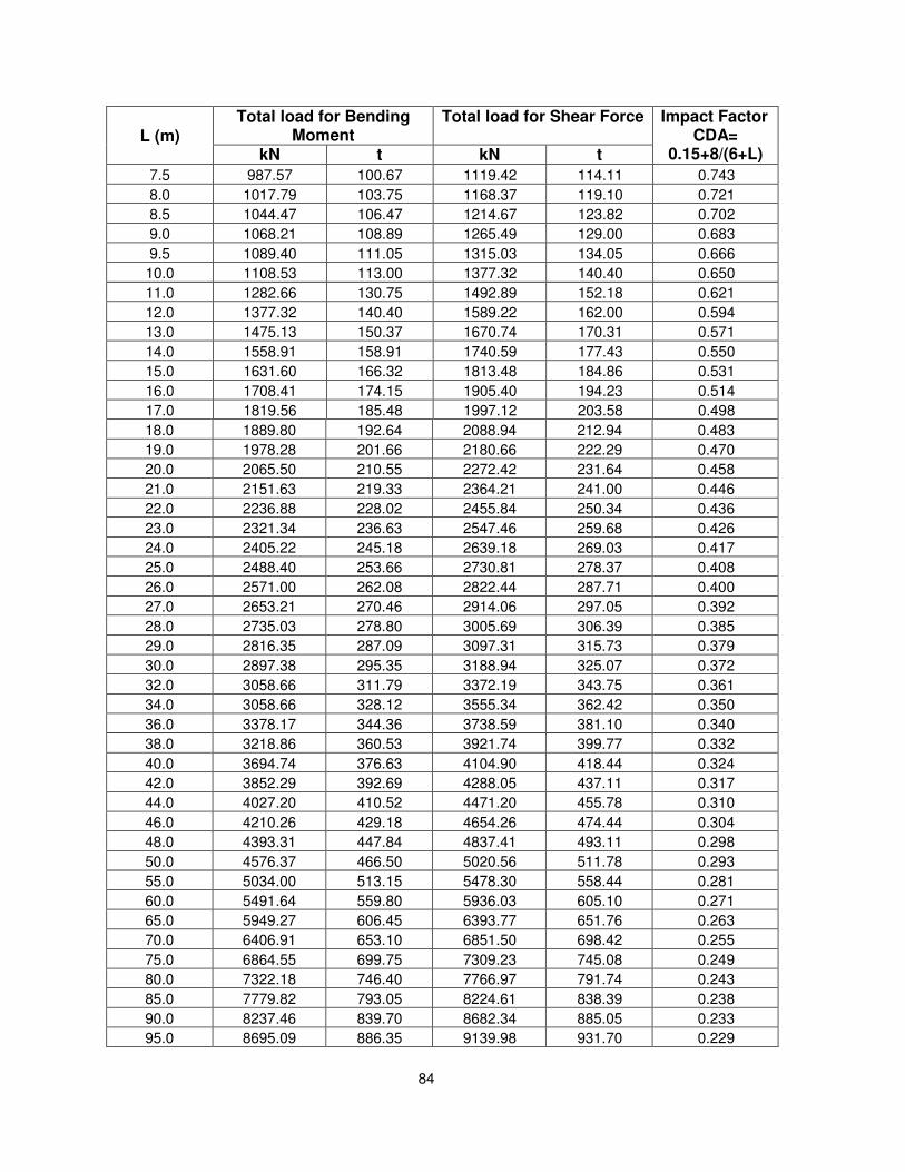
84
L (m) Total load for Bending
Moment Total load for Shear Force Impact Factor
CDA= 0.15+8/(6+L) kN t kN t
7.5 987.57 100.67 1119.42 114.11 0.743
8.0 1017.79 103.75 1168.37 119.10 0.721
8.5 1044.47 106.47 1214.67 123.82 0.702
9.0 1068.21 108.89 1265.49 129.00 0.683
9.5 1089.40 111.05 1315.03 134.05 0.666
10.0 1108.53 113.00 1377.32 140.40 0.650
11.0 1282.66 130.75 1492.89 152.18 0.621
12.0 1377.32 140.40 1589.22 162.00 0.594
13.0 1475.13 150.37 1670.74 170.31 0.571
14.0 1558.91 158.91 1740.59 177.43 0.550
15.0 1631.60 166.32 1813.48 184.86 0.531
16.0 1708.41 174.15 1905.40 194.23 0.514
17.0 1819.56 185.48 1997.12 203.58 0.498
18.0 1889.80 192.64 2088.94 212.94 0.483
19.0 1978.28 201.66 2180.66 222.29 0.470
20.0 2065.50 210.55 2272.42 231.64 0.458
21.0 2151.63 219.33 2364.21 241.00 0.446
22.0 2236.88 228.02 2455.84 250.34 0.436
23.0 2321.34 236.63 2547.46 259.68 0.426
24.0 2405.22 245.18 2639.18 269.03 0.417
25.0 2488.40 253.66 2730.81 278.37 0.408
26.0 2571.00 262.08 2822.44 287.71 0.400
27.0 2653.21 270.46 2914.06 297.05 0.392
28.0 2735.03 278.80 3005.69 306.39 0.385
29.0 2816.35 287.09 3097.31 315.73 0.379
30.0 2897.38 295.35 3188.94 325.07 0.372
32.0 3058.66 311.79 3372.19 343.75 0.361
34.0 3058.66 328.12 3555.34 362.42 0.350
36.0 3378.17 344.36 3738.59 381.10 0.340
38.0 3218.86 360.53 3921.74 399.77 0.332
40.0 3694.74 376.63 4104.90 418.44 0.324
42.0 3852.29 392.69 4288.05 437.11 0.317
44.0 4027.20 410.52 4471.20 455.78 0.310
46.0 4210.26 429.18 4654.26 474.44 0.304
48.0 4393.31 447.84 4837.41 493.11 0.298
50.0 4576.37 466.50 5020.56 511.78 0.293
55.0 5034.00 513.15 5478.30 558.44 0.281
60.0 5491.64 559.80 5936.03 605.10 0.271
65.0 5949.27 606.45 6393.77 651.76 0.263
70.0 6406.91 653.10 6851.50 698.42 0.255
75.0 6864.55 699.75 7309.23 745.08 0.249
80.0 7322.18 746.40 7766.97 791.74 0.243
85.0 7779.82 793.05 8224.61 838.39 0.238
90.0 8237.46 839.70 8682.34 885.05 0.233
95.0 8695.09 886.35 9139.98 931.70 0.229
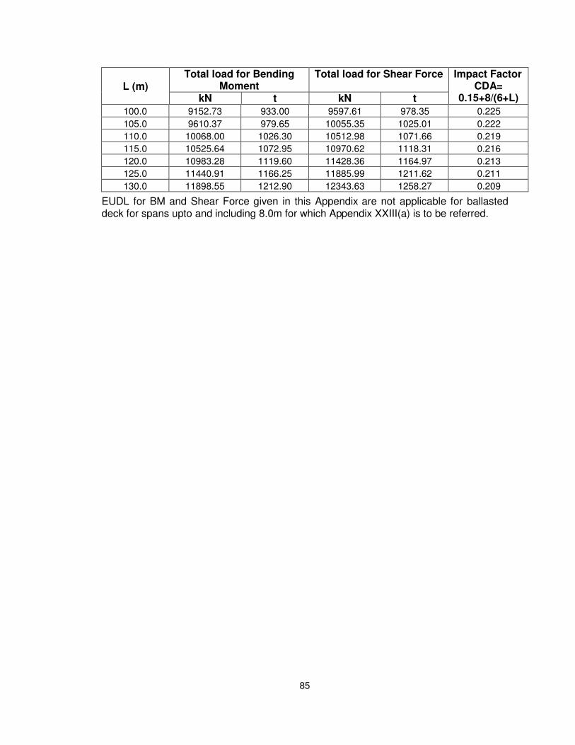
85
L (m) Total load for Bending
Moment Total load for Shear Force Impact Factor
CDA= 0.15+8/(6+L) kN t kN t
100.0 9152.73 933.00 9597.61 978.35 0.225
105.0 9610.37 979.65 10055.35 1025.01 0.222
110.0 10068.00 1026.30 10512.98 1071.66 0.219
115.0 10525.64 1072.95 10970.62 1118.31 0.216
120.0 10983.28 1119.60 11428.36 1164.97 0.213
125.0 11440.91 1166.25 11885.99 1211.62 0.211
130.0 11898.55 1212.90 12343.63 1258.27 0.209
EUDL for BM and Shear Force given in this Appendix are not applicable for ballasted deck for spans upto and including 8.0m for which Appendix XXIII(a) is to be referred.
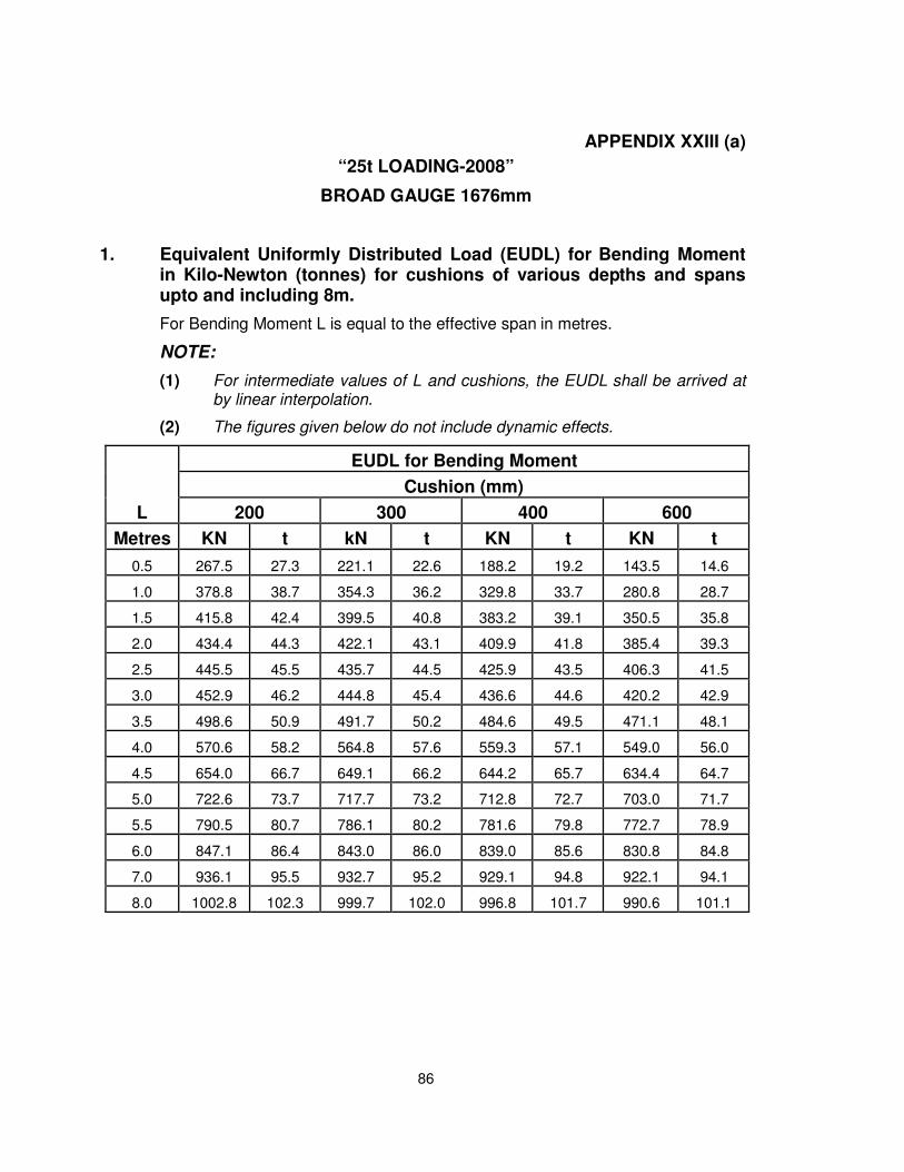
86
APPENDIX XXIII (a)
“25t LOADING-2008”
BROAD GAUGE 1676mm
1. Equivalent Uniformly Distributed Load (EUDL) for Bending Momentin Kilo-Newton (tonnes) for cushions of various depths and spansupto and including 8m.
For Bending Moment L is equal to the effective span in metres.
NOTE:
(1) For intermediate values of L and cushions, the EUDL shall be arrived atby linear interpolation.
(2) The figures given below do not include dynamic effects.
EUDL for Bending Moment
L
Cushion (mm)
200 300 400 600
Metres KN t kN t KN t KN t
0.5 267.5 27.3 221.1 22.6 188.2 19.2 143.5 14.6
1.0 378.8 38.7 354.3 36.2 329.8 33.7 280.8 28.7
1.5 415.8 42.4 399.5 40.8 383.2 39.1 350.5 35.8
2.0 434.4 44.3 422.1 43.1 409.9 41.8 385.4 39.3
2.5 445.5 45.5 435.7 44.5 425.9 43.5 406.3 41.5
3.0 452.9 46.2 444.8 45.4 436.6 44.6 420.2 42.9
3.5 498.6 50.9 491.7 50.2 484.6 49.5 471.1 48.1
4.0 570.6 58.2 564.8 57.6 559.3 57.1 549.0 56.0
4.5 654.0 66.7 649.1 66.2 644.2 65.7 634.4 64.7
5.0 722.6 73.7 717.7 73.2 712.8 72.7 703.0 71.7
5.5 790.5 80.7 786.1 80.2 781.6 79.8 772.7 78.9
6.0 847.1 86.4 843.0 86.0 839.0 85.6 830.8 84.8
7.0 936.1 95.5 932.7 95.2 929.1 94.8 922.1 94.1
8.0 1002.8 102.3 999.7 102.0 996.8 101.7 990.6 101.1
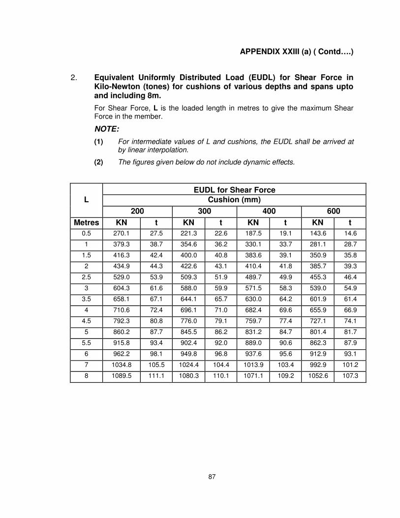
87
APPENDIX XXIII (a) ( Contd….)
2. Equivalent Uniformly Distributed Load (EUDL) for Shear Force inKilo-Newton (tones) for cushions of various depths and spans uptoand including 8m.
For Shear Force, L is the loaded length in metres to give the maximum ShearForce in the member.
NOTE:
(1) For intermediate values of L and cushions, the EUDL shall be arrived atby linear interpolation.
(2) The figures given below do not include dynamic effects.
EUDL for Shear Force
L Cushion (mm)
200 300 400 600
Metres KN t KN t KN t KN t
0.5 270.1 27.5 221.3 22.6 187.5 19.1 143.6 14.6
1 379.3 38.7 354.6 36.2 330.1 33.7 281.1 28.7
1.5 416.3 42.4 400.0 40.8 383.6 39.1 350.9 35.8
2 434.9 44.3 422.6 43.1 410.4 41.8 385.7 39.3
2.5 529.0 53.9 509.3 51.9 489.7 49.9 455.3 46.4
3 604.3 61.6 588.0 59.9 571.5 58.3 539.0 54.9
3.5 658.1 67.1 644.1 65.7 630.0 64.2 601.9 61.4
4 710.6 72.4 696.1 71.0 682.4 69.6 655.9 66.9
4.5 792.3 80.8 776.0 79.1 759.7 77.4 727.1 74.1
5 860.2 87.7 845.5 86.2 831.2 84.7 801.4 81.7
5.5 915.8 93.4 902.4 92.0 889.0 90.6 862.3 87.9
6 962.2 98.1 949.8 96.8 937.6 95.6 912.9 93.1
7 1034.8 105.5 1024.4 104.4 1013.9 103.4 992.9 101.2
8 1089.5 111.1 1080.3 110.1 1071.1 109.2 1052.6 107.3
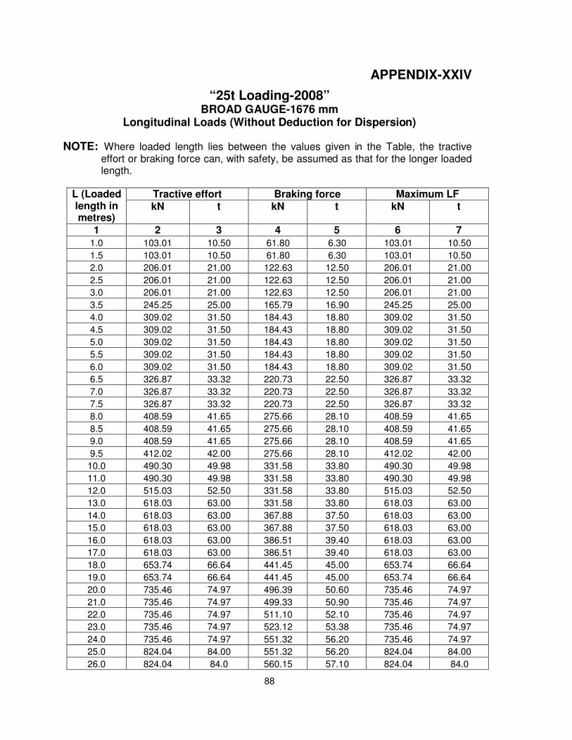
88
APPENDIX-XXIV
“25t Loading-2008” BROAD GAUGE-1676 mm
Longitudinal Loads (Without Deduction for Dispersion)
NOTE: Where loaded length lies between the values given in the Table, the tractive effort or braking force can, with safety, be assumed as that for the longer loaded length.
L (Loaded length in metres)
Tractive effort Braking force Maximum LF kN t kN t kN t
1 2 3 4 5 6 7
1.0 103.01 10.50 61.80 6.30 103.01 10.50
1.5 103.01 10.50 61.80 6.30 103.01 10.50
2.0 206.01 21.00 122.63 12.50 206.01 21.00
2.5 206.01 21.00 122.63 12.50 206.01 21.00
3.0 206.01 21.00 122.63 12.50 206.01 21.00
3.5 245.25 25.00 165.79 16.90 245.25 25.00
4.0 309.02 31.50 184.43 18.80 309.02 31.50
4.5 309.02 31.50 184.43 18.80 309.02 31.50
5.0 309.02 31.50 184.43 18.80 309.02 31.50
5.5 309.02 31.50 184.43 18.80 309.02 31.50
6.0 309.02 31.50 184.43 18.80 309.02 31.50
6.5 326.87 33.32 220.73 22.50 326.87 33.32
7.0 326.87 33.32 220.73 22.50 326.87 33.32
7.5 326.87 33.32 220.73 22.50 326.87 33.32
8.0 408.59 41.65 275.66 28.10 408.59 41.65
8.5 408.59 41.65 275.66 28.10 408.59 41.65
9.0 408.59 41.65 275.66 28.10 408.59 41.65
9.5 412.02 42.00 275.66 28.10 412.02 42.00
10.0 490.30 49.98 331.58 33.80 490.30 49.98
11.0 490.30 49.98 331.58 33.80 490.30 49.98
12.0 515.03 52.50 331.58 33.80 515.03 52.50
13.0 618.03 63.00 331.58 33.80 618.03 63.00
14.0 618.03 63.00 367.88 37.50 618.03 63.00
15.0 618.03 63.00 367.88 37.50 618.03 63.00
16.0 618.03 63.00 386.51 39.40 618.03 63.00
17.0 618.03 63.00 386.51 39.40 618.03 63.00
18.0 653.74 66.64 441.45 45.00 653.74 66.64
19.0 653.74 66.64 441.45 45.00 653.74 66.64
20.0 735.46 74.97 496.39 50.60 735.46 74.97
21.0 735.46 74.97 499.33 50.90 735.46 74.97
22.0 735.46 74.97 511.10 52.10 735.46 74.97
23.0 735.46 74.97 523.12 53.38 735.46 74.97
24.0 735.46 74.97 551.32 56.20 735.46 74.97
25.0 824.04 84.00 551.32 56.20 824.04 84.00
26.0 824.04 84.0 560.15 57.10 824.04 84.0
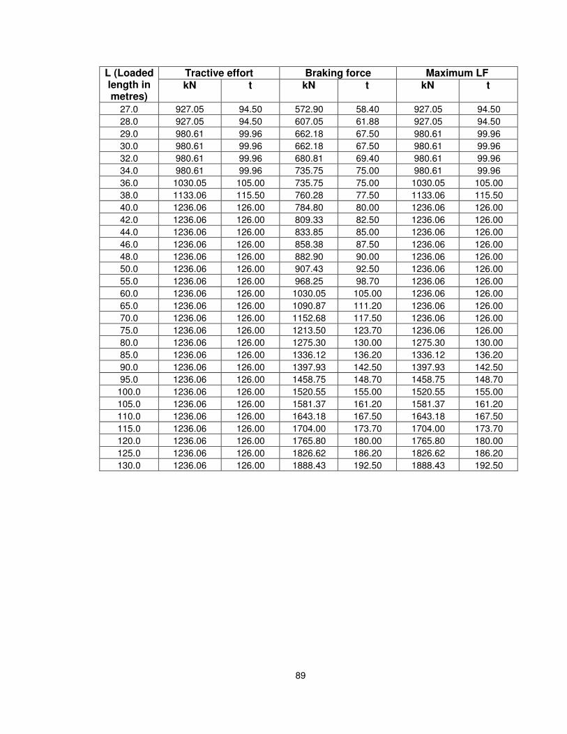
89
L (Loaded length in metres)
Tractive effort Braking force Maximum LF kN t kN t kN t
27.0 927.05 94.50 572.90 58.40 927.05 94.50
28.0 927.05 94.50 607.05 61.88 927.05 94.50
29.0 980.61 99.96 662.18 67.50 980.61 99.96
30.0 980.61 99.96 662.18 67.50 980.61 99.96
32.0 980.61 99.96 680.81 69.40 980.61 99.96
34.0 980.61 99.96 735.75 75.00 980.61 99.96
36.0 1030.05 105.00 735.75 75.00 1030.05 105.00
38.0 1133.06 115.50 760.28 77.50 1133.06 115.50
40.0 1236.06 126.00 784.80 80.00 1236.06 126.00
42.0 1236.06 126.00 809.33 82.50 1236.06 126.00
44.0 1236.06 126.00 833.85 85.00 1236.06 126.00
46.0 1236.06 126.00 858.38 87.50 1236.06 126.00
48.0 1236.06 126.00 882.90 90.00 1236.06 126.00
50.0 1236.06 126.00 907.43 92.50 1236.06 126.00
55.0 1236.06 126.00 968.25 98.70 1236.06 126.00
60.0 1236.06 126.00 1030.05 105.00 1236.06 126.00
65.0 1236.06 126.00 1090.87 111.20 1236.06 126.00
70.0 1236.06 126.00 1152.68 117.50 1236.06 126.00
75.0 1236.06 126.00 1213.50 123.70 1236.06 126.00
80.0 1236.06 126.00 1275.30 130.00 1275.30 130.00
85.0 1236.06 126.00 1336.12 136.20 1336.12 136.20
90.0 1236.06 126.00 1397.93 142.50 1397.93 142.50
95.0 1236.06 126.00 1458.75 148.70 1458.75 148.70
100.0 1236.06 126.00 1520.55 155.00 1520.55 155.00
105.0 1236.06 126.00 1581.37 161.20 1581.37 161.20
110.0 1236.06 126.00 1643.18 167.50 1643.18 167.50
115.0 1236.06 126.00 1704.00 173.70 1704.00 173.70
120.0 1236.06 126.00 1765.80 180.00 1765.80 180.00
125.0 1236.06 126.00 1826.62 186.20 1826.62 186.20
130.0 1236.06 126.00 1888.43 192.50 1888.43 192.50
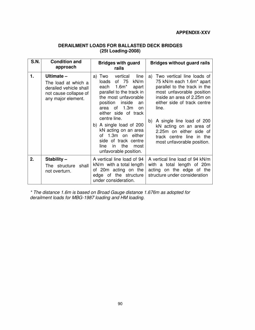
90
APPENDIX-XXV
DERAILMENT LOADS FOR BALLASTED DECK BRIDGES (25t Loading-2008)
S.N. Condition and approach
Bridges with guard rails
Bridges without guard rails
1. Ultimate –
The load at which a derailed vehicle shall not cause collapse of any major element.
a) Two vertical line loads of 75 kN/m each 1.6m* apart parallel to the track in the most unfavorable position inside an area of 1.3m on either side of track centre line.
b) A single load of 200kN acting on an areaof 1.3m on eitherside of track centreline in the mostunfavorable position.
a) Two vertical line loads of75 kN/m each 1.6m* apartparallel to the track in themost unfavorable positioninside an area of 2.25m oneither side of track centreline.
b) A single line load of 200kN acting on an area of2.25m on either side oftrack centre line in themost unfavorable position.
2. Stability –
The structure shall not overturn.
A vertical line load of 94 kN/m with a total length of 20m acting on the edge of the structure under consideration.
A vertical line load of 94 kN/m with a total length of 20m acting on the edge of the structure under consideration
* The distance 1.6m is based on Broad Gauge distance 1.676m as adopted forderailment loads for MBG-1987 loading and HM loading.

91
AP
PE
ND
IX X
XV
I
SH
EE
T 1
OF
4
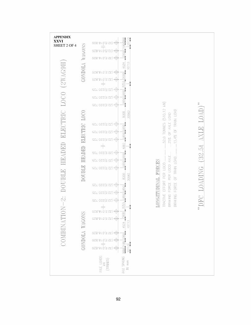
92
APPENDIX
XXVI
SHEET 2 OF 4
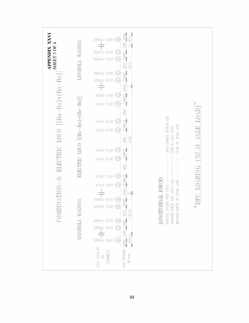
93
AP
PE
ND
IX X
XV
I
SH
EE
T 3
OF
4
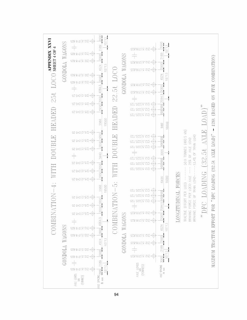
94
AP
PE
ND
IX
XX
VI
SH
EE
T 4
OF
4
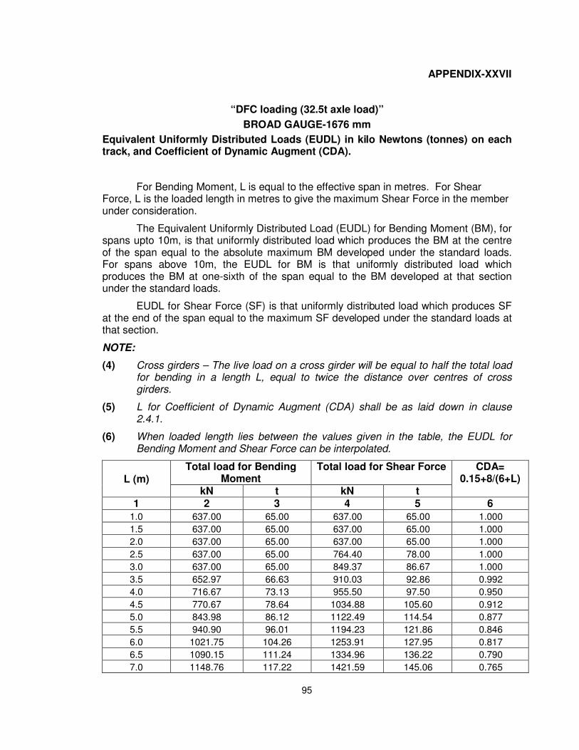
95
APPENDIX-XXVII
“DFC loading (32.5t axle load)”
BROAD GAUGE-1676 mm
Equivalent Uniformly Distributed Loads (EUDL) in kilo Newtons (tonnes) on each track, and Coefficient of Dynamic Augment (CDA).
For Bending Moment, L is equal to the effective span in metres. For Shear Force, L is the loaded length in metres to give the maximum Shear Force in the member under consideration.
The Equivalent Uniformly Distributed Load (EUDL) for Bending Moment (BM), for spans upto 10m, is that uniformly distributed load which produces the BM at the centre of the span equal to the absolute maximum BM developed under the standard loads. For spans above 10m, the EUDL for BM is that uniformly distributed load which produces the BM at one-sixth of the span equal to the BM developed at that section under the standard loads.
EUDL for Shear Force (SF) is that uniformly distributed load which produces SF at the end of the span equal to the maximum SF developed under the standard loads at that section.
NOTE:
(4) Cross girders – The live load on a cross girder will be equal to half the total loadfor bending in a length L, equal to twice the distance over centres of crossgirders.
(5) L for Coefficient of Dynamic Augment (CDA) shall be as laid down in clause2.4.1.
(6) When loaded length lies between the values given in the table, the EUDL forBending Moment and Shear Force can be interpolated.
L (m) Total load for Bending
Moment Total load for Shear Force CDA=
0.15+8/(6+L) kN t kN t
1 2 3 4 5 6
1.0 637.00 65.00 637.00 65.00 1.000
1.5 637.00 65.00 637.00 65.00 1.000
2.0 637.00 65.00 637.00 65.00 1.000
2.5 637.00 65.00 764.40 78.00 1.000
3.0 637.00 65.00 849.37 86.67 1.000
3.5 652.97 66.63 910.03 92.86 0.992
4.0 716.67 73.13 955.50 97.50 0.950
4.5 770.67 78.64 1034.88 105.60 0.912
5.0 843.98 86.12 1122.49 114.54 0.877
5.5 940.90 96.01 1194.23 121.86 0.846
6.0 1021.75 104.26 1253.91 127.95 0.817
6.5 1090.15 111.24 1334.96 136.22 0.790
7.0 1148.76 117.22 1421.59 145.06 0.765
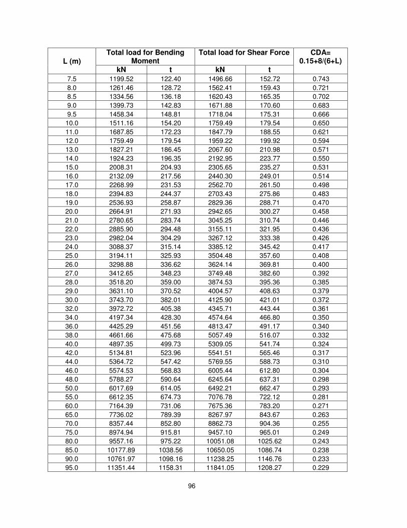
96
L (m) Total load for Bending
Moment Total load for Shear Force CDA=
0.15+8/(6+L) kN t kN t
7.5 1199.52 122.40 1496.66 152.72 0.743
8.0 1261.46 128.72 1562.41 159.43 0.721
8.5 1334.56 136.18 1620.43 165.35 0.702
9.0 1399.73 142.83 1671.88 170.60 0.683
9.5 1458.34 148.81 1718.04 175.31 0.666
10.0 1511.16 154.20 1759.49 179.54 0.650
11.0 1687.85 172.23 1847.79 188.55 0.621
12.0 1759.49 179.54 1959.22 199.92 0.594
13.0 1827.21 186.45 2067.60 210.98 0.571
14.0 1924.23 196.35 2192.95 223.77 0.550
15.0 2008.31 204.93 2305.65 235.27 0.531
16.0 2132.09 217.56 2440.30 249.01 0.514
17.0 2268.99 231.53 2562.70 261.50 0.498
18.0 2394.83 244.37 2703.43 275.86 0.483
19.0 2536.93 258.87 2829.36 288.71 0.470
20.0 2664.91 271.93 2942.65 300.27 0.458
21.0 2780.65 283.74 3045.25 310.74 0.446
22.0 2885.90 294.48 3155.11 321.95 0.436
23.0 2982.04 304.29 3267.12 333.38 0.426
24.0 3088.37 315.14 3385.12 345.42 0.417
25.0 3194.11 325.93 3504.48 357.60 0.408
26.0 3298.88 336.62 3624.14 369.81 0.400
27.0 3412.65 348.23 3749.48 382.60 0.392
28.0 3518.20 359.00 3874.53 395.36 0.385
29.0 3631.10 370.52 4004.57 408.63 0.379
30.0 3743.70 382.01 4125.90 421.01 0.372
32.0 3972.72 405.38 4345.71 443.44 0.361
34.0 4197.34 428.30 4574.64 466.80 0.350
36.0 4425.29 451.56 4813.47 491.17 0.340
38.0 4661.66 475.68 5057.49 516.07 0.332
40.0 4897.35 499.73 5309.05 541.74 0.324
42.0 5134.81 523.96 5541.51 565.46 0.317
44.0 5364.72 547.42 5769.55 588.73 0.310
46.0 5574.53 568.83 6005.44 612.80 0.304
48.0 5788.27 590.64 6245.64 637.31 0.298
50.0 6017.69 614.05 6492.21 662.47 0.293
55.0 6612.35 674.73 7076.78 722.12 0.281
60.0 7164.39 731.06 7675.36 783.20 0.271
65.0 7736.02 789.39 8267.97 843.67 0.263
70.0 8357.44 852.80 8862.73 904.36 0.255
75.0 8974.94 915.81 9457.10 965.01 0.249
80.0 9557.16 975.22 10051.08 1025.62 0.243
85.0 10177.89 1038.56 10650.05 1086.74 0.238
90.0 10761.97 1098.16 11238.25 1146.76 0.233
95.0 11351.44 1158.31 11841.05 1208.27 0.229
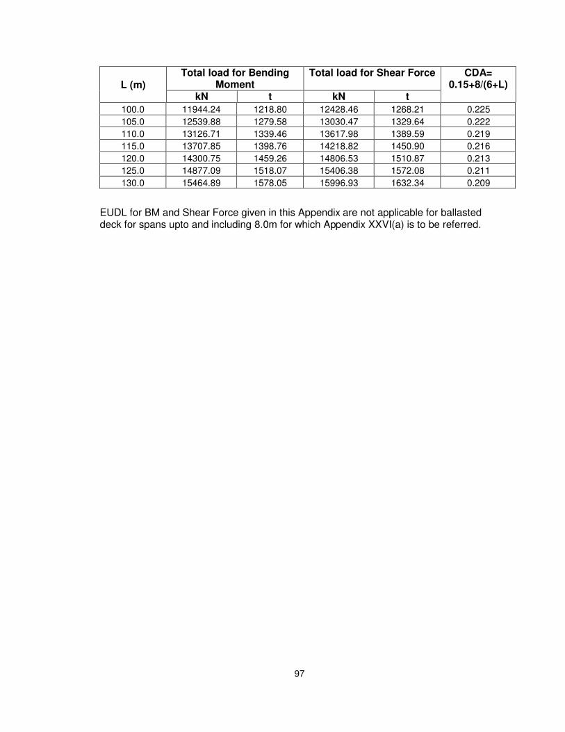
97
L (m) Total load for Bending
Moment Total load for Shear Force CDA=
0.15+8/(6+L) kN t kN t
100.0 11944.24 1218.80 12428.46 1268.21 0.225
105.0 12539.88 1279.58 13030.47 1329.64 0.222
110.0 13126.71 1339.46 13617.98 1389.59 0.219
115.0 13707.85 1398.76 14218.82 1450.90 0.216
120.0 14300.75 1459.26 14806.53 1510.87 0.213
125.0 14877.09 1518.07 15406.38 1572.08 0.211
130.0 15464.89 1578.05 15996.93 1632.34 0.209
EUDL for BM and Shear Force given in this Appendix are not applicable for ballasted deck for spans upto and including 8.0m for which Appendix XXVI(a) is to be referred.
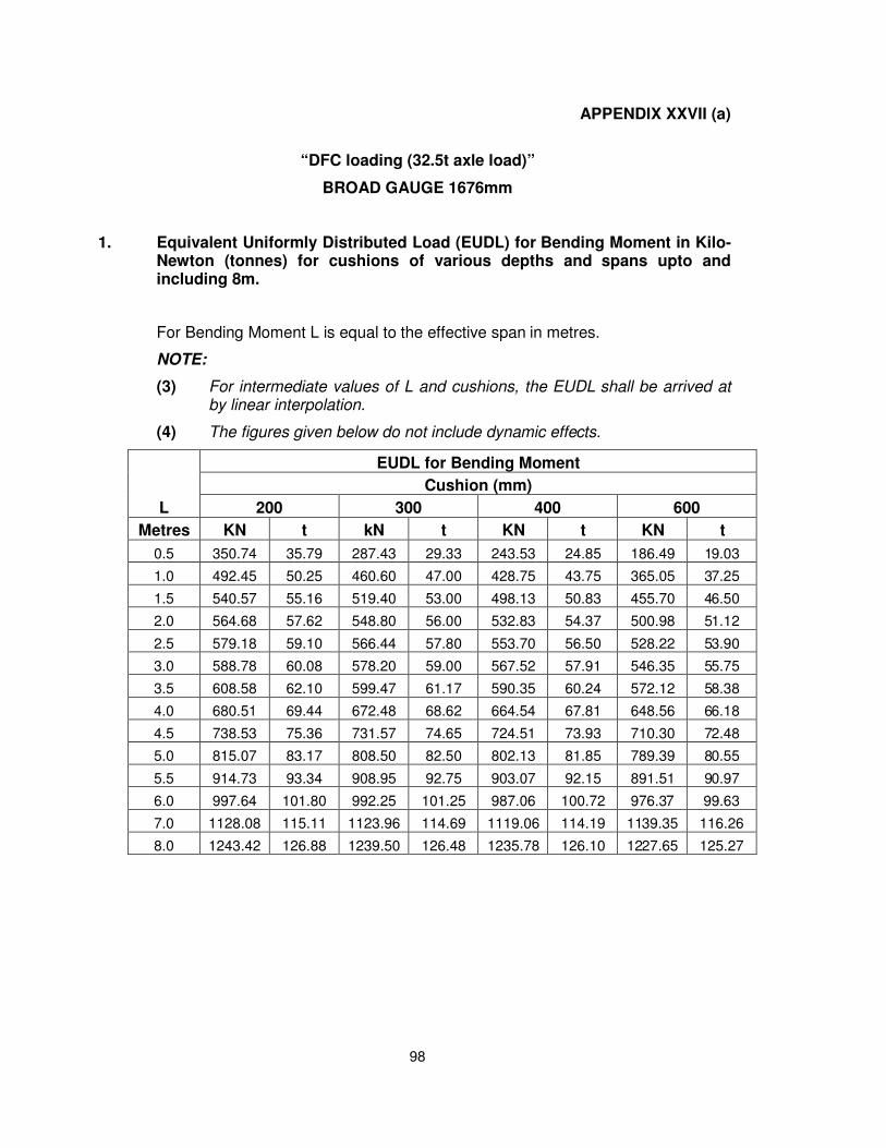
98
APPENDIX XXVII (a)
“DFC loading (32.5t axle load)”
BROAD GAUGE 1676mm
1. Equivalent Uniformly Distributed Load (EUDL) for Bending Moment in Kilo-Newton (tonnes) for cushions of various depths and spans upto andincluding 8m.
For Bending Moment L is equal to the effective span in metres.
NOTE:
(3) For intermediate values of L and cushions, the EUDL shall be arrived atby linear interpolation.
(4) The figures given below do not include dynamic effects.
L
EUDL for Bending Moment
Cushion (mm)
200 300 400 600
Metres KN t kN t KN t KN t
0.5 350.74 35.79 287.43 29.33 243.53 24.85 186.49 19.03
1.0 492.45 50.25 460.60 47.00 428.75 43.75 365.05 37.25
1.5 540.57 55.16 519.40 53.00 498.13 50.83 455.70 46.50
2.0 564.68 57.62 548.80 56.00 532.83 54.37 500.98 51.12
2.5 579.18 59.10 566.44 57.80 553.70 56.50 528.22 53.90
3.0 588.78 60.08 578.20 59.00 567.52 57.91 546.35 55.75
3.5 608.58 62.10 599.47 61.17 590.35 60.24 572.12 58.38
4.0 680.51 69.44 672.48 68.62 664.54 67.81 648.56 66.18
4.5 738.53 75.36 731.57 74.65 724.51 73.93 710.30 72.48
5.0 815.07 83.17 808.50 82.50 802.13 81.85 789.39 80.55
5.5 914.73 93.34 908.95 92.75 903.07 92.15 891.51 90.97
6.0 997.64 101.80 992.25 101.25 987.06 100.72 976.37 99.63
7.0 1128.08 115.11 1123.96 114.69 1119.06 114.19 1139.35 116.26
8.0 1243.42 126.88 1239.50 126.48 1235.78 126.10 1227.65 125.27
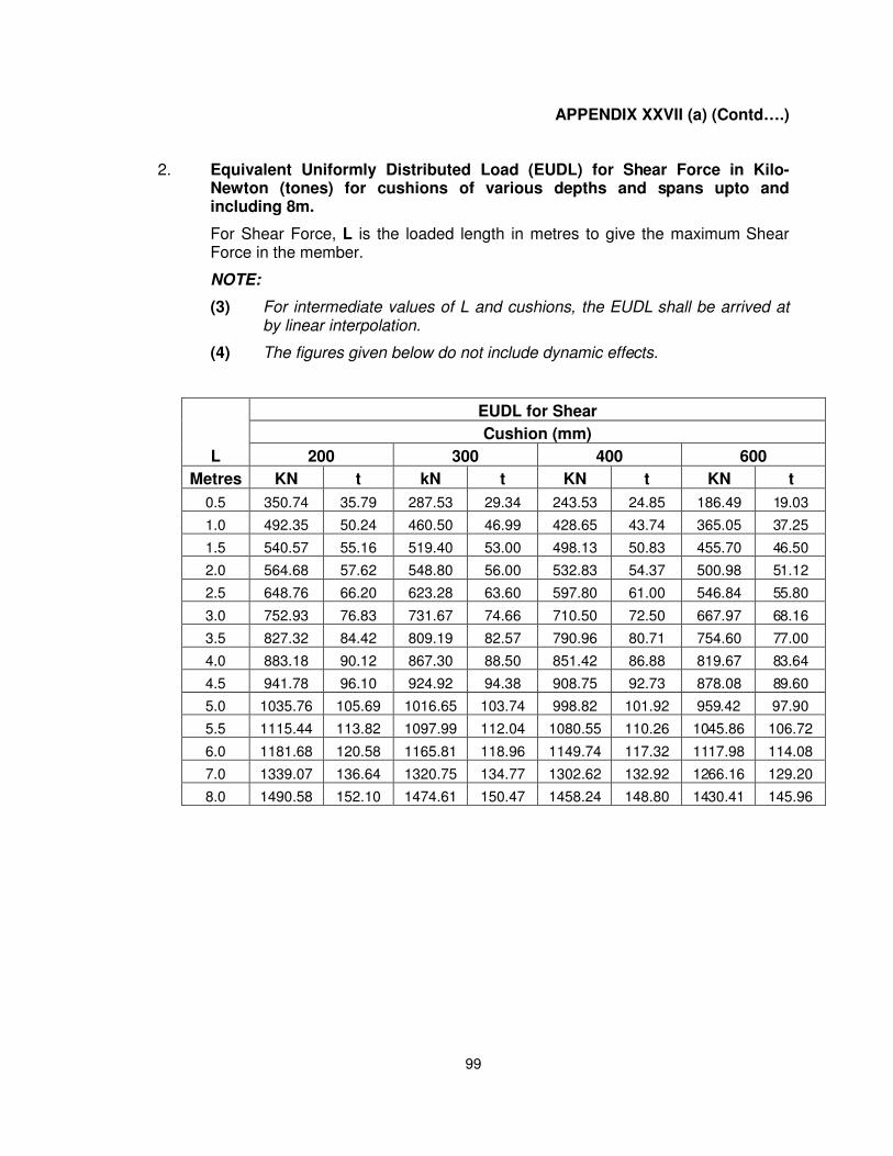
99
APPENDIX XXVII (a) (Contd….)
2. Equivalent Uniformly Distributed Load (EUDL) for Shear Force in Kilo-Newton (tones) for cushions of various depths and spans upto andincluding 8m.
For Shear Force, L is the loaded length in metres to give the maximum ShearForce in the member.
NOTE:
(3) For intermediate values of L and cushions, the EUDL shall be arrived atby linear interpolation.
(4) The figures given below do not include dynamic effects.
L
EUDL for Shear
Cushion (mm)
200 300 400 600
Metres KN t kN t KN t KN t
0.5 350.74 35.79 287.53 29.34 243.53 24.85 186.49 19.03
1.0 492.35 50.24 460.50 46.99 428.65 43.74 365.05 37.25
1.5 540.57 55.16 519.40 53.00 498.13 50.83 455.70 46.50
2.0 564.68 57.62 548.80 56.00 532.83 54.37 500.98 51.12
2.5 648.76 66.20 623.28 63.60 597.80 61.00 546.84 55.80
3.0 752.93 76.83 731.67 74.66 710.50 72.50 667.97 68.16
3.5 827.32 84.42 809.19 82.57 790.96 80.71 754.60 77.00
4.0 883.18 90.12 867.30 88.50 851.42 86.88 819.67 83.64
4.5 941.78 96.10 924.92 94.38 908.75 92.73 878.08 89.60
5.0 1035.76 105.69 1016.65 103.74 998.82 101.92 959.42 97.90
5.5 1115.44 113.82 1097.99 112.04 1080.55 110.26 1045.86 106.72
6.0 1181.68 120.58 1165.81 118.96 1149.74 117.32 1117.98 114.08
7.0 1339.07 136.64 1320.75 134.77 1302.62 132.92 1266.16 129.20
8.0 1490.58 152.10 1474.61 150.47 1458.24 148.80 1430.41 145.96
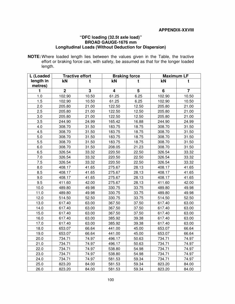
100
APPENDIX-XXVIII
“DFC loading (32.5t axle load)” BROAD GAUGE-1676 mm
Longitudinal Loads (Without Deduction for Dispersion)
NOTE: Where loaded length lies between the values given in the Table, the tractive effort or braking force can, with safety, be assumed as that for the longer loaded length.
L (Loaded length in metres)
Tractive effort Braking force Maximum LF kN t kN t kN t
1 2 3 4 5 6 7
1.0 102.90 10.50 61.25 6.25 102.90 10.50
1.5 102.90 10.50 61.25 6.25 102.90 10.50
2.0 205.80 21.00 122.50 12.50 205.80 21.00
2.5 205.80 21.00 122.50 12.50 205.80 21.00
3.0 205.80 21.00 122.50 12.50 205.80 21.00
3.5 244.90 24.99 165.42 16.88 244.90 24.99
4.0 308.70 31.50 183.75 18.75 308.70 31.50
4.5 308.70 31.50 183.75 18.75 308.70 31.50
5.0 308.70 31.50 183.75 18.75 308.70 31.50
5.5 308.70 31.50 183.75 18.75 308.70 31.50
6.0 308.70 31.50 208.05 21.23 308.70 31.50
6.5 326.54 33.32 220.50 22.50 326.54 33.32
7.0 326.54 33.32 220.50 22.50 326.54 33.32
7.5 326.54 33.32 220.50 22.50 326.54 33.32
8.0 408.17 41.65 275.67 28.13 408.17 41.65
8.5 408.17 41.65 275.67 28.13 408.17 41.65
9.0 408.17 41.65 275.67 28.13 408.17 41.65
9.5 411.60 42.00 275.67 28.13 411.60 42.00
10.0 489.80 49.98 330.75 33.75 489.80 49.98
11.0 489.80 49.98 330.75 33.75 489.80 49.98
12.0 514.50 52.50 330.75 33.75 514.50 52.50
13.0 617.40 63.00 367.50 37.50 617.40 63.00
14.0 617.40 63.00 367.50 37.50 617.40 63.00
15.0 617.40 63.00 367.50 37.50 617.40 63.00
16.0 617.40 63.00 385.92 39.38 617.40 63.00
17.0 617.40 63.00 385.92 39.38 617.40 63.00
18.0 653.07 66.64 441.00 45.00 653.07 66.64
19.0 653.07 66.64 441.00 45.00 653.07 66.64
20.0 734.71 74.97 496.17 50.63 734.71 74.97
21.0 734.71 74.97 496.17 50.63 734.71 74.97
22.0 734.71 74.97 538.80 54.98 734.71 74.97
23.0 734.71 74.97 538.80 54.98 734.71 74.97
24.0 734.71 74.97 581.53 59.34 734.71 74.97
25.0 823.20 84.00 581.53 59.34 823.20 84.00
26.0 823.20 84.00 581.53 59.34 823.20 84.00
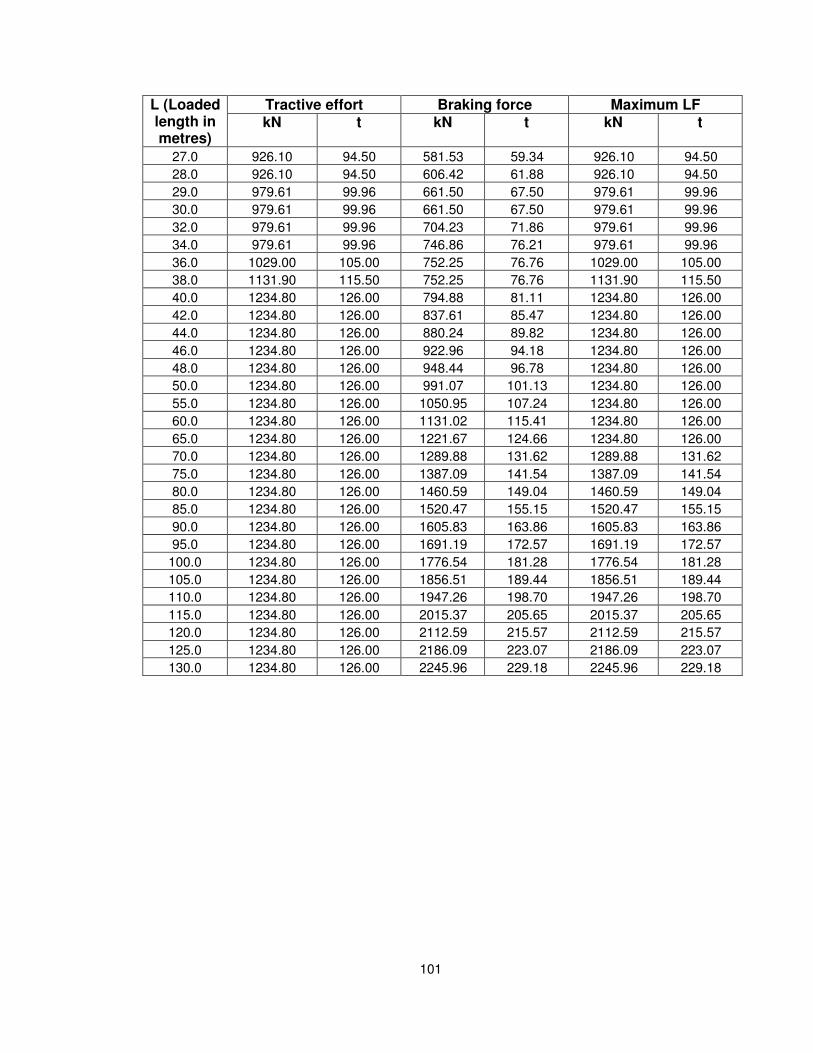
101
L (Loaded length in metres)
Tractive effort Braking force Maximum LF kN t kN t kN t
27.0 926.10 94.50 581.53 59.34 926.10 94.50
28.0 926.10 94.50 606.42 61.88 926.10 94.50
29.0 979.61 99.96 661.50 67.50 979.61 99.96
30.0 979.61 99.96 661.50 67.50 979.61 99.96
32.0 979.61 99.96 704.23 71.86 979.61 99.96
34.0 979.61 99.96 746.86 76.21 979.61 99.96
36.0 1029.00 105.00 752.25 76.76 1029.00 105.00
38.0 1131.90 115.50 752.25 76.76 1131.90 115.50
40.0 1234.80 126.00 794.88 81.11 1234.80 126.00
42.0 1234.80 126.00 837.61 85.47 1234.80 126.00
44.0 1234.80 126.00 880.24 89.82 1234.80 126.00
46.0 1234.80 126.00 922.96 94.18 1234.80 126.00
48.0 1234.80 126.00 948.44 96.78 1234.80 126.00
50.0 1234.80 126.00 991.07 101.13 1234.80 126.00
55.0 1234.80 126.00 1050.95 107.24 1234.80 126.00
60.0 1234.80 126.00 1131.02 115.41 1234.80 126.00
65.0 1234.80 126.00 1221.67 124.66 1234.80 126.00
70.0 1234.80 126.00 1289.88 131.62 1289.88 131.62
75.0 1234.80 126.00 1387.09 141.54 1387.09 141.54
80.0 1234.80 126.00 1460.59 149.04 1460.59 149.04
85.0 1234.80 126.00 1520.47 155.15 1520.47 155.15
90.0 1234.80 126.00 1605.83 163.86 1605.83 163.86
95.0 1234.80 126.00 1691.19 172.57 1691.19 172.57
100.0 1234.80 126.00 1776.54 181.28 1776.54 181.28
105.0 1234.80 126.00 1856.51 189.44 1856.51 189.44
110.0 1234.80 126.00 1947.26 198.70 1947.26 198.70
115.0 1234.80 126.00 2015.37 205.65 2015.37 205.65
120.0 1234.80 126.00 2112.59 215.57 2112.59 215.57
125.0 1234.80 126.00 2186.09 223.07 2186.09 223.07
130.0 1234.80 126.00 2245.96 229.18 2245.96 229.18
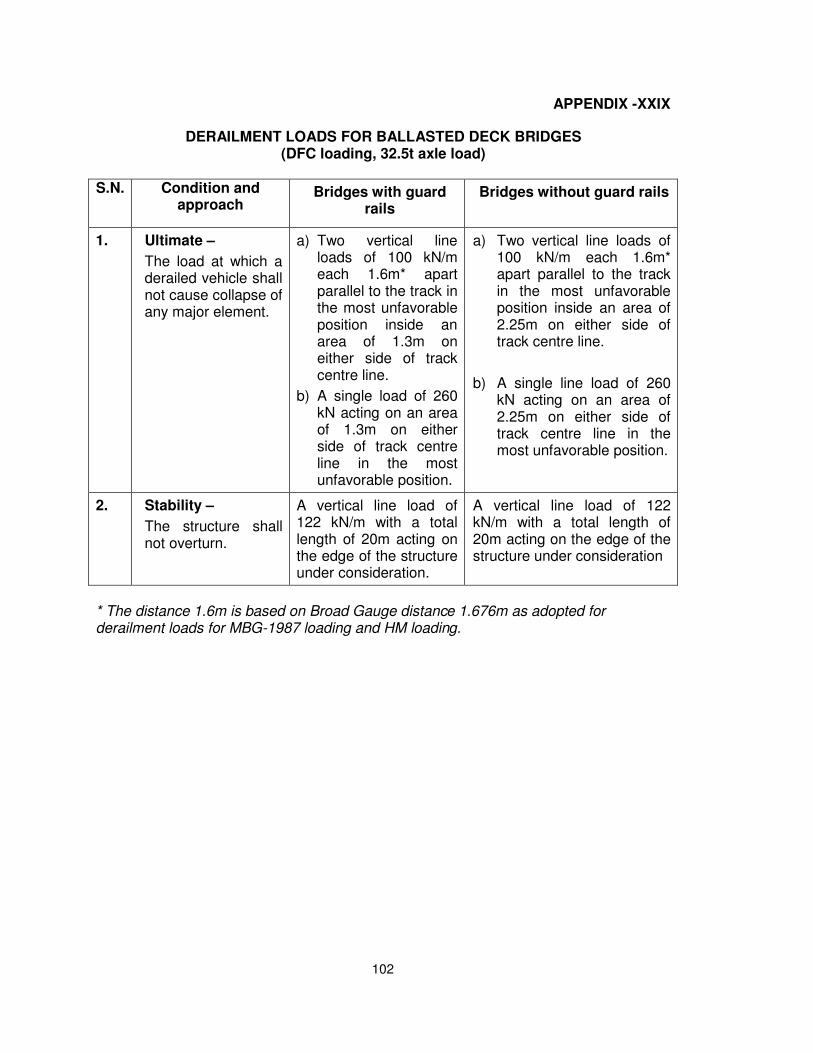
102
APPENDIX -XXIX
DERAILMENT LOADS FOR BALLASTED DECK BRIDGES (DFC loading, 32.5t axle load)
S.N. Condition and approach
Bridges with guard rails
Bridges without guard rails
1. Ultimate –
The load at which a derailed vehicle shall not cause collapse of any major element.
a) Two vertical line loads of 100 kN/m each 1.6m* apart parallel to the track in the most unfavorable position inside an area of 1.3m on either side of track centre line.
b) A single load of 260kN acting on an areaof 1.3m on eitherside of track centreline in the mostunfavorable position.
a) Two vertical line loads of100 kN/m each 1.6m*apart parallel to the trackin the most unfavorableposition inside an area of2.25m on either side oftrack centre line.
b) A single line load of 260kN acting on an area of2.25m on either side oftrack centre line in themost unfavorable position.
2. Stability –
The structure shall not overturn.
A vertical line load of 122 kN/m with a total length of 20m acting on the edge of the structure under consideration.
A vertical line load of 122 kN/m with a total length of 20m acting on the edge of the structure under consideration
* The distance 1.6m is based on Broad Gauge distance 1.676m as adopted forderailment loads for MBG-1987 loading and HM loading.
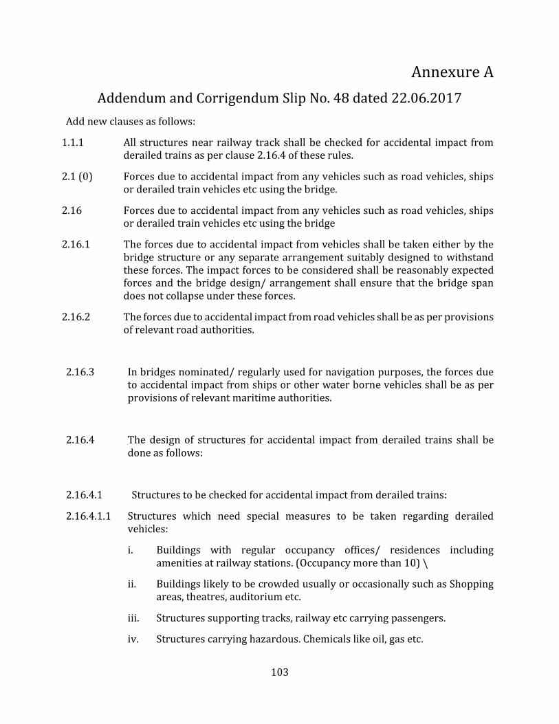
103
Annexure A Addendum and Corrigendum Slip No. 48 dated 22.06.2017
Add new clauses as follows:
1.1.1 All structures near railway track shall be checked for accidental impact from derailed trains as per clause 2.16.4 of these rules.
2.1 (0) Forces due to accidental impact from any vehicles such as road vehicles, ships or derailed train vehicles etc using the bridge.
2.16 Forces due to accidental impact from any vehicles such as road vehicles, ships or derailed train vehicles etc using the bridge
2.16.1 The forces due to accidental impact from vehicles shall be taken either by the bridge structure or any separate arrangement suitably designed to withstand these forces. The impact forces to be considered shall be reasonably expected forces and the bridge design/ arrangement shall ensure that the bridge span does not collapse under these forces.
2.16.2 The forces due to accidental impact from road vehicles shall be as per provisions of relevant road authorities.
2.16.3 In bridges nominated/ regularly used for navigation purposes, the forces due to accidental impact from ships or other water borne vehicles shall be as per provisions of relevant maritime authorities.
2.16.4 The design of structures for accidental impact from derailed trains shall be done as follows:
2.16.4.1 Structures to be checked for accidental impact from derailed trains:
2.16.4.1.1 Structures which need special measures to be taken regarding derailed vehicles:
i. Buildings with regular occupancy offices/ residences includingamenities at railway stations. (Occupancy more than 10) \
ii. Buildings likely to be crowded usually or occasionally such as Shoppingareas, theatres, auditorium etc.
iii. Structures supporting tracks, railway etc carrying passengers.
iv. Structures carrying hazardous. Chemicals like oil, gas etc.
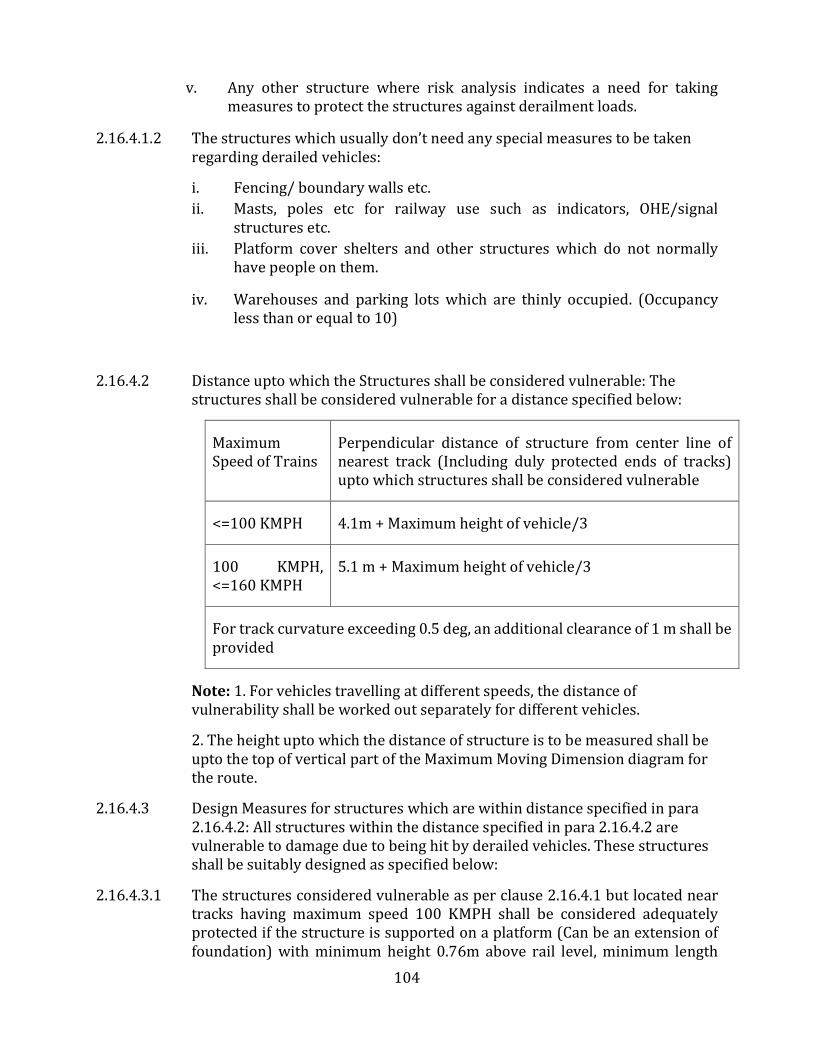
104
v. Any other structure where risk analysis indicates a need for takingmeasures to protect the structures against derailment loads.
2.16.4.1.2 The structures which usually don’t need any special measures to be taken regarding derailed vehicles:
i. Fencing/ boundary walls etc.ii. Masts, poles etc for railway use such as indicators, OHE/signal
structures etc.iii. Platform cover shelters and other structures which do not normally
have people on them.
iv. Warehouses and parking lots which are thinly occupied. (Occupancyless than or equal to 10)
2.16.4.2 Distance upto which the Structures shall be considered vulnerable: The structures shall be considered vulnerable for a distance specified below:
Maximum Speed of Trains
Perpendicular distance of structure from center line of nearest track (Including duly protected ends of tracks) upto which structures shall be considered vulnerable
<=100 KMPH 4.1m + Maximum height of vehicle/3
100 KMPH, <=160 KMPH
5.1 m + Maximum height of vehicle/3
For track curvature exceeding 0.5 deg, an additional clearance of 1 m shall be provided
Note: 1. For vehicles travelling at different speeds, the distance of vulnerability shall be worked out separately for different vehicles.
2. The height upto which the distance of structure is to be measured shall beupto the top of vertical part of the Maximum Moving Dimension diagram forthe route.
2.16.4.3 Design Measures for structures which are within distance specified in para 2.16.4.2: All structures within the distance specified in para 2.16.4.2 are vulnerable to damage due to being hit by derailed vehicles. These structures shall be suitably designed as specified below:
2.16.4.3.1 The structures considered vulnerable as per clause 2.16.4.1 but located near tracks having maximum speed 100 KMPH shall be considered adequately protected if the structure is supported on a platform (Can be an extension of foundation) with minimum height 0.76m above rail level, minimum length
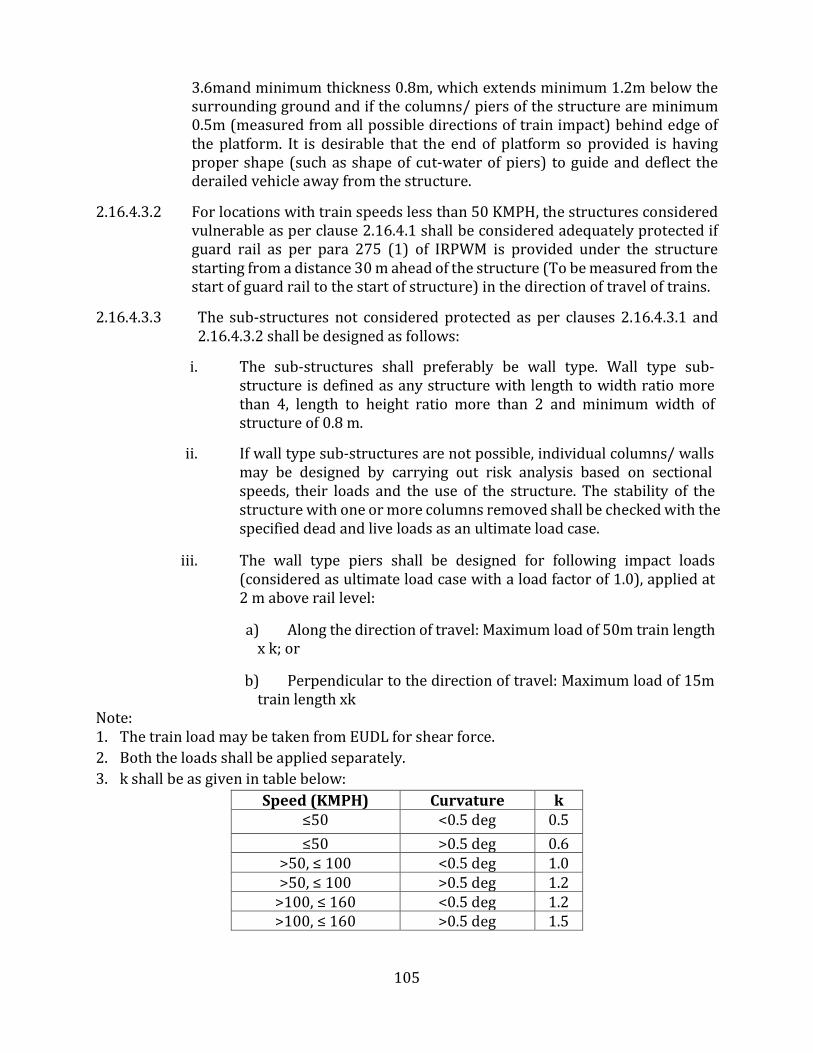
105
3.6mand minimum thickness 0.8m, which extends minimum 1.2m below the surrounding ground and if the columns/ piers of the structure are minimum 0.5m (measured from all possible directions of train impact) behind edge of the platform. It is desirable that the end of platform so provided is having proper shape (such as shape of cut-water of piers) to guide and deflect the derailed vehicle away from the structure.
2.16.4.3.2 For locations with train speeds less than 50 KMPH, the structures considered vulnerable as per clause 2.16.4.1 shall be considered adequately protected if guard rail as per para 275 (1) of IRPWM is provided under the structure starting from a distance 30 m ahead of the structure (To be measured from the start of guard rail to the start of structure) in the direction of travel of trains.
2.16.4.3.3 The sub-structures not considered protected as per clauses 2.16.4.3.1 and 2.16.4.3.2 shall be designed as follows:
i. The sub-structures shall preferably be wall type. Wall type sub-structure is defined as any structure with length to width ratio morethan 4, length to height ratio more than 2 and minimum width ofstructure of 0.8 m.
ii. If wall type sub-structures are not possible, individual columns/ wallsmay be designed by carrying out risk analysis based on sectionalspeeds, their loads and the use of the structure. The stability of thestructure with one or more columns removed shall be checked with thespecified dead and live loads as an ultimate load case.
iii. The wall type piers shall be designed for following impact loads(considered as ultimate load case with a load factor of 1.0), applied at2 m above rail level:
a) Along the direction of travel: Maximum load of 50m train lengthx k; or
b) Perpendicular to the direction of travel: Maximum load of 15mtrain length xk
Note: 1. The train load may be taken from EUDL for shear force.2. Both the loads shall be applied separately.3. k shall be as given in table below:
Speed (KMPH) Curvature k ≤50 <0.5 deg 0.5 ≤50 >0.5 deg 0.6
>50, ≤ 100 <0.5 deg 1.0 >50, ≤ 100 >0.5 deg 1.2
>100, ≤ 160 <0.5 deg 1.2 >100, ≤ 160 >0.5 deg 1.5