Embed Size (px)
Citation preview
BRIDGE NAVIGATIONAL WATCHALARM SYSTEM (BNWAS)
BR-500
OPERATOR'S MANUAL
www.furuno.com
MODEL

The paper used in this manual
is elemental chlorine free.
・FURUNO Authorized Distributor/Dealer
9-52 Ashihara-cho,
Nishinomiya, 662-8580, JAPAN
Telephone : +81-(0)798-65-2111
Fax : +81-(0)798-65-4200
A : MAR 2011.Printed in JapanAll rights reserved.
C : NOV . 02, 2011
Pub. No. OME-44610-C
*00017461812**00017461812*(TAYA ) BR-500*00017461812**00017461812*
* 0 0 0 1 7 4 6 1 8 1 2 *
i
IMPORTANT NOTICES
General• This manual has been authored with simplified grammar, to meet the needs of international us-
ers.• The operator of this equipment must read and follow the descriptions in this manual. Wrong op-
eration or maintenance can cancel the warranty or cause injury.• Do not copy any part of this manual without written permission from FURUNO.• If this manual is lost or worn, contact your dealer about replacement.• The contents of this manual and equipment specifications can change without notice.• The example screens (or illustrations) shown in this manual can be different from the screens
you see on your display. The screens you see depend on your system configuration and equip-ment settings.
• Save this manual for future reference.• Any modification of the equipment (including software) by persons not authorized by FURUNO
will cancel the warranty.• All brand and product names are trademarks, registered trademarks or service marks of their
respective holders.
How to discard this productDiscard this product according to local regulations for the disposal of industrial waste. For disposal in the USA, see the homepage of the Electronics Industries Alliance (http://www.eiae.org/) for the correct method of disposal.
How to discard a used batterySome FURUNO products have a battery(ies). To see if your product has a battery, see the chapter on Maintenance. Follow the instructions below if a battery is used. Tape the + and - terminals of battery before disposal to prevent fire, heat generation caused by short circuit.
In the European Union
The crossed-out trash can symbol indicates that all types of batteries must not be discarded in standard trash, or at a trash site. Take the used batteries to a battery collection site according to your national legislation and the Batteries Directive 2006/66/EU.
In the USA
The Mobius loop symbol (three chasing arrows) indicates that Ni-Cd and lead-acid rechargeable batteries must be recycled. Take the used batteries to a battery collection site according to local laws.
In the other countries
There are no international standards for the battery recycle symbol. The number of symbols can increase when the other countries make their own recycle symbols in the future.
Cd
PbNi-Cd
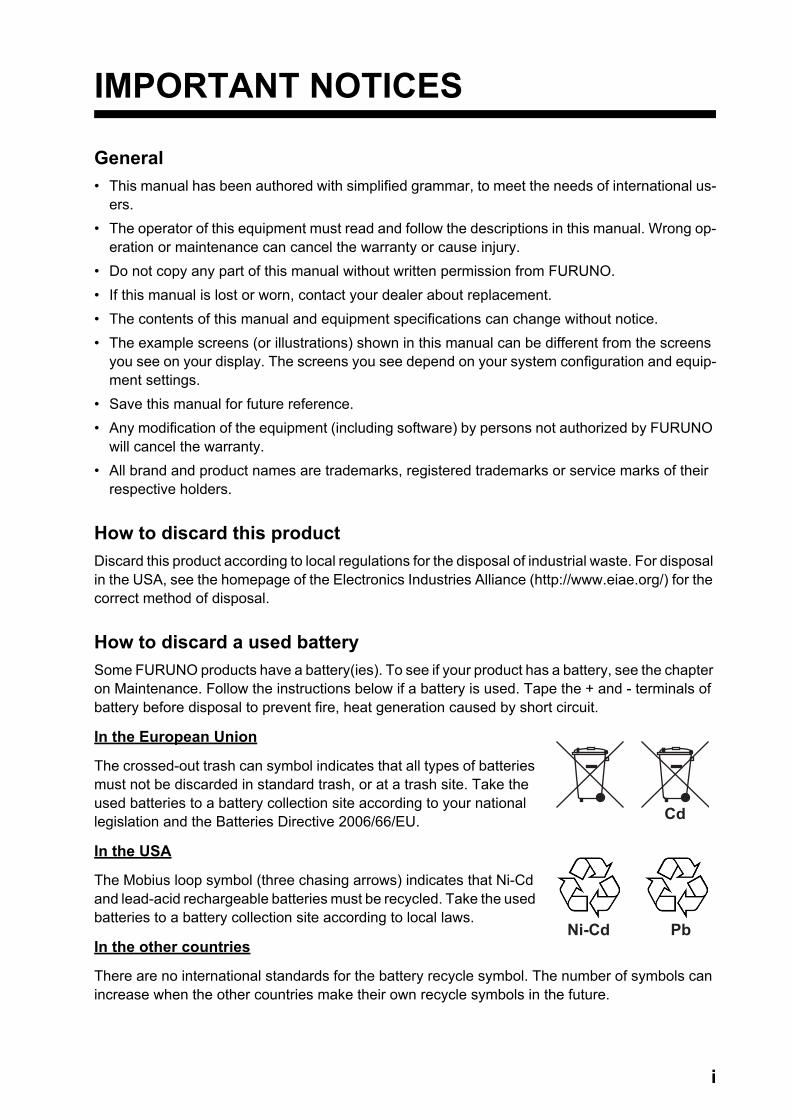
SAFETY INSTRUCTIONS
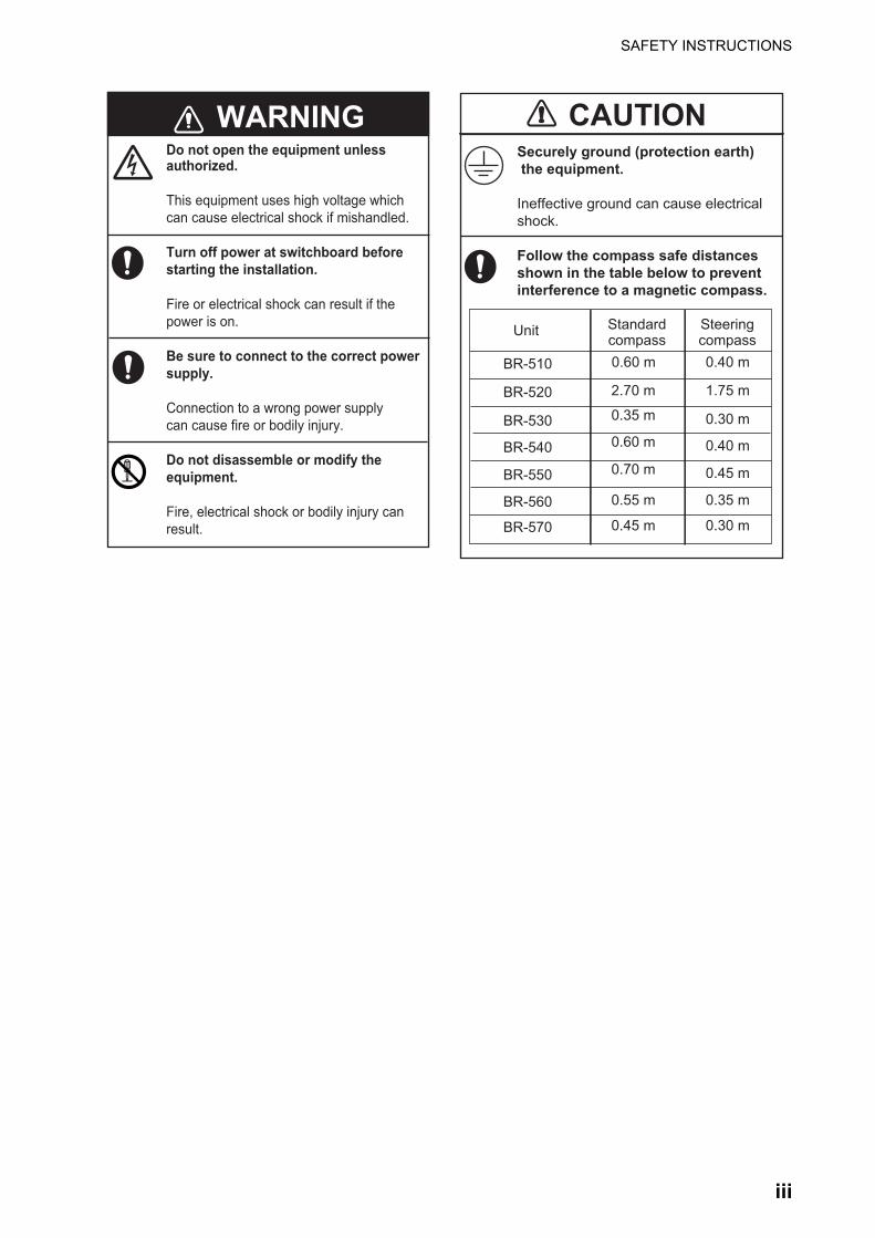
CAUTION
WARNING
Mandatory ActionProhibitive ActionWarning, Caution
Warning LabelA warning label is attached to the processor unit.Do not remove the label. If the label is missingor damaged, see your dealer about replacement.
Do not disassemble or modify theequipment.
Fire, electrical shock or bodily injurycan result.
Do not operate the equipment withwet hands.
Fire or electrical shock can result.
Keep the equipment away from rain,water and water splash.
Fire or electrical shock can result if watergets into the equipment.
Use the correct fuse.
Use of a wrong fuse can cause bodilyinjury or fire.
Do not open the equipment.
This equipment uses high voltage that cancause electrical shock.Only qualified persons can work insidethe equipment.
Turn off power at switchboard if thesomething is dropped inside the equipment.
Fire or electrical shock can result if thepower remains on.
Turn off power at switchboard if the equipment is emitting smoke or fire.
Fire or electrical shock can result if thepower remains on.
Indicates a condition that can cause death or serious injury ifnot avoided.
Indicates a condition that can cause minor or moderate injury ifnot avoided.
WARNING CAUTION
WARNINGTo avoid electrical shock, do not remove cover. No user-serviceable parts inside.
Read these safety instructions before you operate or install the equipment.
Name: Warning Label (1)Type: 86-003-1011-3Code No.: 100-236-233-10
ii
SAFETY INSTRUCTIONS
CAUTIONWARNINGSecurely ground (protection earth) the equipment.
Ineffective ground can cause electricalshock.
Follow the compass safe distancesshown in the table below to preventinterference to a magnetic compass.
Do not open the equipment unlessauthorized.
This equipment uses high voltage whichcan cause electrical shock if mishandled.
Turn off power at switchboard beforestarting the installation.
Fire or electrical shock can result if thepower is on.
Be sure to connect to the correct powersupply.
Connection to a wrong power supplycan cause fire or bodily injury.
Do not disassemble or modify theequipment.
Fire, electrical shock or bodily injury canresult.
Steeringcompass
Standardcompass
Unit
0.60 mBR-510 0.40 m
1.75 m
0.30 m
2.70 m
0.35 m
0.40 m0.60 m
0.45 m0.70 m
0.35 m0.55 m
BR-520
BR-530
BR-540
BR-550
BR-5600.30 m0.45 mBR-570
iii
TABLE OF CONTENTS
FOREWORD ...................................................................................................................viSYSTEM CONFIGURATION ........................................................................................viii1. MAIN ALARM PANEL ...........................................................................................1-11.1 Controls...................................................................................................................... 1-11.2 How to Turn the System On/Off ................................................................................. 1-11.3 BNWAS Display ......................................................................................................... 1-21.4 How to Adjust the LCD/LED Brilliance, Key Backlighting........................................... 1-31.5 How to Select the Backup Officer .............................................................................. 1-41.6 Mode .......................................................................................................................... 1-41.7 Watch Alarm Sequence ............................................................................................. 1-51.8 Help Area ...................................................................................................................1-8
1.8.1 System failure indications .............................................................................. 1-81.8.2 Operational event indications......................................................................... 1-9
1.9 How to Make an Emergency Call............................................................................... 1-91.10 How to Call a Navigation Officer .............................................................................. 1-10
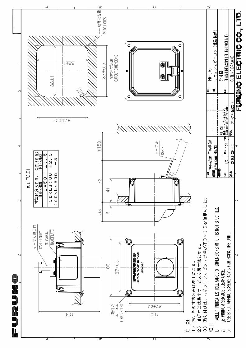
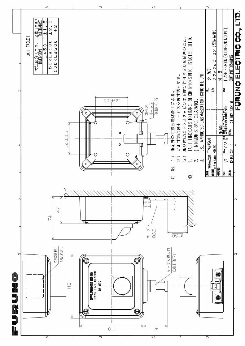
2. OPTIONAL EQUIPMENT.......................................................................................2-12.1 Timer Reset Panel BR-530, BR-550 .......................................................................... 2-12.2 Cabin Panel BR-540 .................................................................................................. 2-22.3 Motion Detector BR-560............................................................................................. 2-32.4 Flash Beacon BR-570 ................................................................................................ 2-4
3. MAINTENANCE, TROUBLESHOOTING...............................................................3-13.1 Maintenance............................................................................................................... 3-13.2 Fuse Replacement ..................................................................................................... 3-23.3 Troubleshooting ......................................................................................................... 3-23.4 How to Check Connection Between Processor Unit/Cabin Panel/
Timer Reset Panel ..................................................................................................... 3-33.5 Life Expectancy of Major Parts .................................................................................. 3-4
4. INSTALLATION .....................................................................................................4-14.1 Equipment Lists.......................................................................................................... 4-14.2 Mounting Considerations ........................................................................................... 4-24.3 Main Alarm Panel BR-510.......................................................................................... 4-3
4.3.1 Desktop mount ............................................................................................... 4-34.3.2 Flush mount ................................................................................................... 4-34.3.3 Shield film (option) ......................................................................................... 4-4
4.4 Processor Unit BR-520 .............................................................................................. 4-44.5 Timer Reset Panel BR-530, Cabin Panel BR-540, Motion Detector BR-560,
Flash Beacon BR-570 (optional units) ....................................................................... 4-44.5.1 Flush mount ................................................................................................... 4-44.5.2 Bulkhead mount (option) ................................................................................ 4-5
4.6 Watertight Timer Reset Panel BR-550 (option).......................................................... 4-94.7 Wiring ....................................................................................................................... 4-11
4.7.1 Processor Unit.............................................................................................. 4-114.7.2 Wiring information ........................................................................................ 4-134.7.3 Main Alarm Panel......................................................................................... 4-144.7.4 Timer Reset Panel, Cabin Panel, Motion Detector, Flash Beacon .............. 4-144.7.5 Flash Beacon ............................................................................................... 4-154.7.6 How to fabricate cables for the Cabin Panel, Timer Reset Panel,
Flash Beacon and Motion Detector.............................................................. 4-15
iv

TABLE OF CONTENTS
4.8 DIP Switch, Rotary Switch Settings..........................................................................4-164.9 How to Adjust LED Brilliance....................................................................................4-174.10 Menu Settings...........................................................................................................4-17
4.10.1 Administrator Menu ......................................................................................4-174.10.2 Service Menu ...............................................................................................4-21
4.11 I/O Sentence Information..........................................................................................4-22
APPENDIX 1 MENU TREE, ABBREVIATIONS, JIS CABLE GUIDE ......................AP-1SPECIFICATIONS ..................................................................................................... SP-1INDEX ......................................................................................................................... IN-1
v
FOREWORD
A Word to the Owner of the BR-500Congratulations on your choice of the FURUNO BR-500 Bridge Navigational Watch Alarm System (BNWAS). We are confident you will see why the FURUNO name has become synonymous with quality and reliability.
Since 1948, FURUNO Electric Company has enjoyed an enviable reputation for innovative and dependable marine electronics equipment. This dedication to excellence is furthered by our ex-tensive global network of agents and dealers.
Your equipment is designed and constructed to meet the rigorous demands of the marine envi-ronment. However, no machine can perform its intended function unless properly operated and maintained. Please carefully read and follow the operation and maintenance procedures set forth in this manual.
Thank you for considering and purchasing FURUNO.
We would appreciate feedback from you, the end-user, about whether we are achieving our pur-poses.
FeaturesThe BR-500 monitors the Officer of the Watch’s (OOW) presence on the bridge to prevent mari-time casualties. The system sends an alarm to the quarters of the backup officer if the OOW fails to respond to the active alarm or emergency call.
• Complies with IMO MSC.128(75).• Watches for unattended bridge and operator disability.• Transmits alarm to backup officer if the OOW fails to respond to active alarm or emergency call.• Motion Detector (option) detects motion on the bridge to confirm operator fitness.• Flash Beacon (option) flashes to remind OOW to confirm presence (by operating equipment in
the system).
Software history
xx: minor change
Main Alarm Panel Program Processor Unit Program
BOOT: 2450054-01.xx Initial version 09/2010 APPLICA-TION: 2450056-01.xx
BOOT: 2450058-01.xx Initial version 09/2010 APPLI-CATION: 2450060-01.xxCPLD: 2450065-01.xx
vi
FOREWORD
Usage precautionsBack-up power supply
The BR-500 is not equipped with a back-up power supply. Use an external back-up power supply (24 VDC) when the main or auxiliary power fails.
Motion Detector (BR-560)
The Motion Detector judges motion by the amount of temperature change within the detection area. If the area has source(s) of heat other than personnel or the temperature change is too small, detection of motion may not be possible. Keep the following points in mind:Motion is mis-detected when• movement in sleep is judged as motion.• movement by small animal(s) is judged as motion.• equipment that circulates air (air conditioner, etc.), steam-generating warmers and the like
causes temperature change.• sunlight or shade in the detection area causes temperature change.Motion cannot be detected if• the temperature change in personnel or detection area is too small.• personnel motion is too fast or too slow• there is an impedance between personnel and the Motion Detector.The Motion Detector can be affected by sunlight. Install it in a place well away from sunlight.
Alarm ACK signal
The BR-500 receives the Alarm ACK signal in contact signal format only. It cannot receive the sig-nal in serial format.
Resetting the watch alarm timer
Reset the watch alarm timer from the Timer Reset Panel, which is installed next to the Main Alarm Panel.
vii
viii
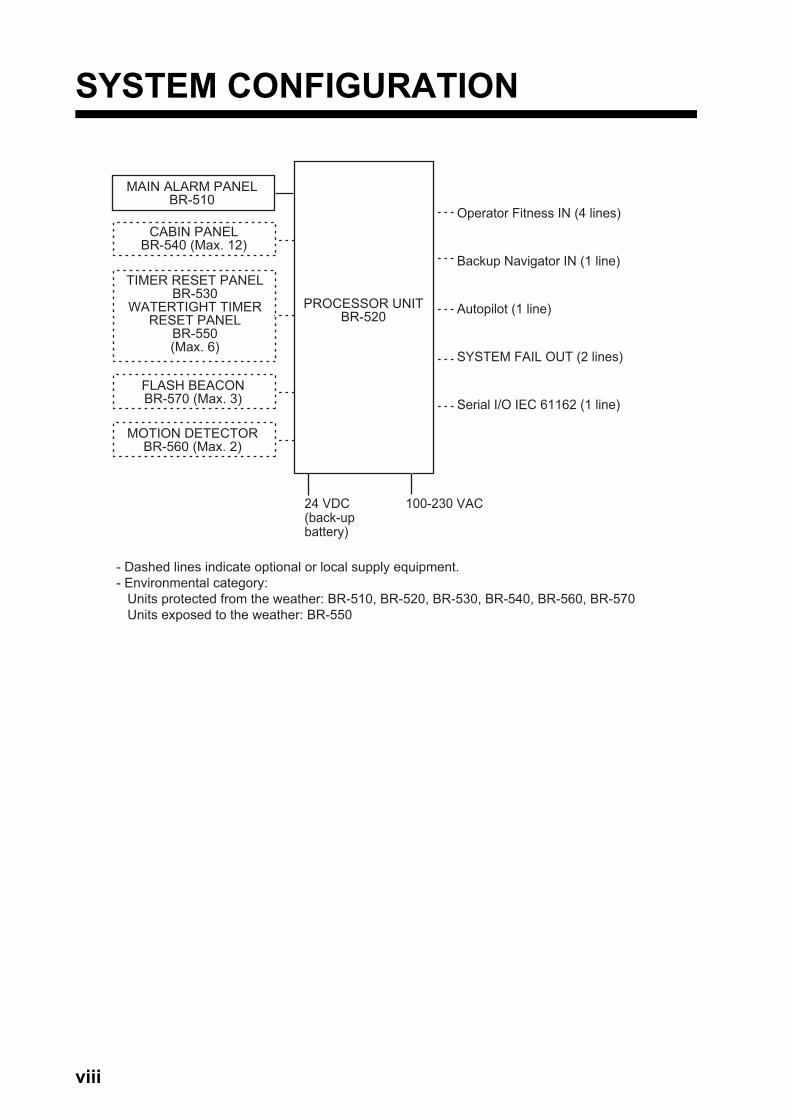
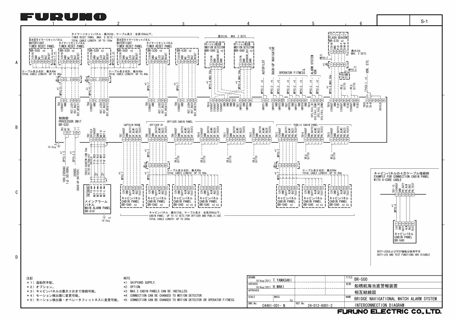
SYSTEM CONFIGURATION
PROCESSOR UNITBR-520
100-230 VAC
MAIN ALARM PANELBR-510
CABIN PANELBR-540 (Max. 12)
TIMER RESET PANELBR-530
WATERTIGHT TIMER RESET PANEL
BR-550(Max. 6)
FLASH BEACONBR-570 (Max. 3)
MOTION DETECTORBR-560 (Max. 2)
Operator Fitness IN (4 lines)
Backup Navigator IN (1 line)
Autopilot (1 line)
SYSTEM FAIL OUT (2 lines)
Serial I/O IEC 61162 (1 line)
- Dashed lines indicate optional or local supply equipment.- Environmental category: Units protected from the weather: BR-510, BR-520, BR-530, BR-540, BR-560, BR-570 Units exposed to the weather: BR-550
24 VDC (back-upbattery)
1. MAIN ALARM PANEL
The Main Alarm Panel is the heart of the BNWAS. All settings are done from the Main Alarm Panel.
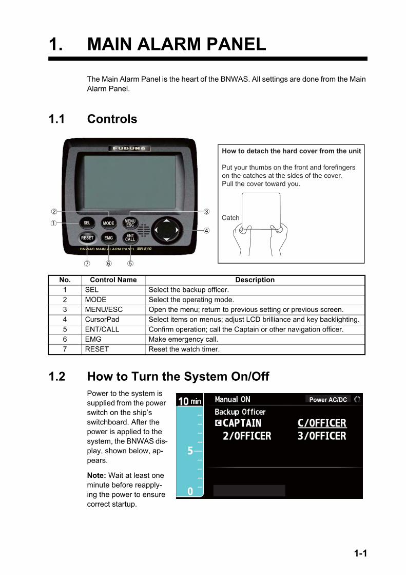
1.1 Controls
1.2 How to Turn the System On/OffPower to the system is supplied from the power switch on the ship’s switchboard. After the power is applied to the system, the BNWAS dis-play, shown below, ap-pears.
Note: Wait at least one minute before reapply-ing the power to ensure correct startup.
No. Control Name Description1 SEL Select the backup officer.2 MODE Select the operating mode.3 MENU/ESC Open the menu; return to previous setting or previous screen.4 CursorPad Select items on menus; adjust LCD brilliance and key backlighting.5 ENT/CALL Confirm operation; call the Captain or other navigation officer.6 EMG Make emergency call.7 RESET Reset the watch timer.
How to detach the hard cover from the unit
Put your thumbs on the front and forefingers on the catches at the sides of the cover.Pull the cover toward you.
Catch
Power AC/DC
1-1
1. MAIN ALARM PANEL
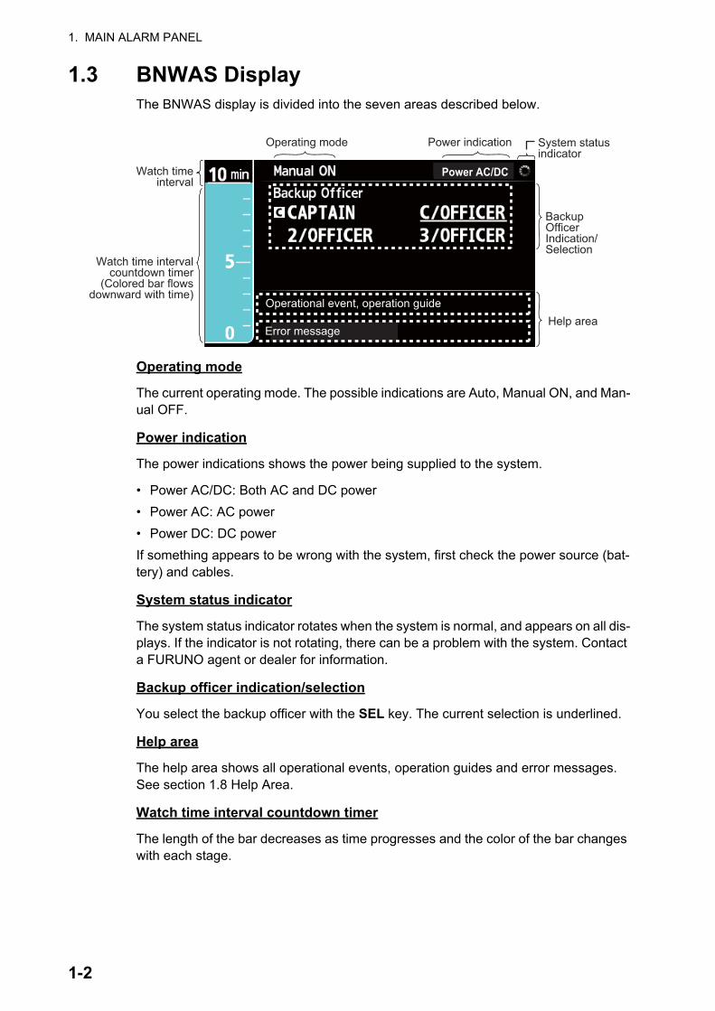
1.3 BNWAS DisplayThe BNWAS display is divided into the seven areas described below.
Operating mode
The current operating mode. The possible indications are Auto, Manual ON, and Man-ual OFF.
Power indication
The power indications shows the power being supplied to the system.
• Power AC/DC: Both AC and DC power• Power AC: AC power• Power DC: DC powerIf something appears to be wrong with the system, first check the power source (bat-tery) and cables.
System status indicator
The system status indicator rotates when the system is normal, and appears on all dis-plays. If the indicator is not rotating, there can be a problem with the system. Contact a FURUNO agent or dealer for information.
Backup officer indication/selection
You select the backup officer with the SEL key. The current selection is underlined.
Help area
The help area shows all operational events, operation guides and error messages. See section 1.8 Help Area.
Watch time interval countdown timer
The length of the bar decreases as time progresses and the color of the bar changes with each stage.
Power AC/DCPower AC/DC
Operating mode Power indication System statusindicator
Operational event, operation guide
Watch time interval
Watch time intervalcountdown timer
(Colored bar flowsdownward with time)
Error messageHelp area
Backup OfficerIndication/Selection
1-2
1. MAIN ALARM PANEL
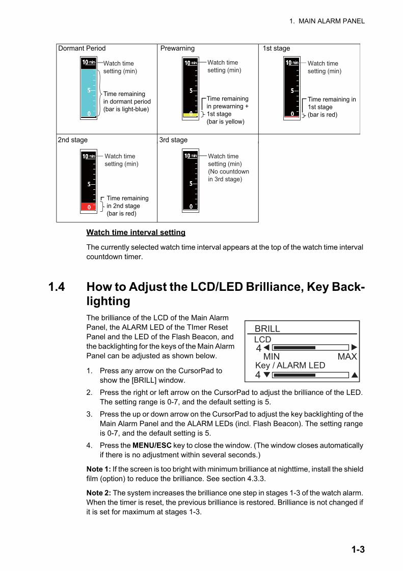
Watch time interval setting
The currently selected watch time interval appears at the top of the watch time interval countdown timer.
1.4 How to Adjust the LCD/LED Brilliance, Key Back-lightingThe brilliance of the LCD of the Main Alarm Panel, the ALARM LED of the TImer Reset Panel and the LED of the Flash Beacon, and the backlighting for the keys of the Main Alarm Panel can be adjusted as shown below.
1. Press any arrow on the CursorPad to show the [BRILL] window.
2. Press the right or left arrow on the CursorPad to adjust the brilliance of the LED. The setting range is 0-7, and the default setting is 5.
3. Press the up or down arrow on the CursorPad to adjust the key backlighting of the Main Alarm Panel and the ALARM LEDs (incl. Flash Beacon). The setting range is 0-7, and the default setting is 5.
4. Press the MENU/ESC key to close the window. (The window closes automatically if there is no adjustment within several seconds.)
Note 1: If the screen is too bright with minimum brilliance at nighttime, install the shield film (option) to reduce the brilliance. See section 4.3.3.
Note 2: The system increases the brilliance one step in stages 1-3 of the watch alarm. When the timer is reset, the previous brilliance is restored. Brilliance is not changed if it is set for maximum at stages 1-3.
2nd stage 3rd stage
Time remaining in1st stage(bar is red)
Time remainingin dormant period(bar is light-blue)
Watch timesetting (min)
Dormant Period Prewarning 1st stage
Watch timesetting (min)
Watch timesetting (min)
Time remainingin prewarning +1st stage(bar is yellow)
Watch timesetting (min)(No countdownin 3rd stage)
Watch timesetting (min)
Time remainingin 2nd stage(bar is red)
BRILLLCD
MIN MAXKey / ALARM LED
4
4
1-3
1. MAIN ALARM PANEL
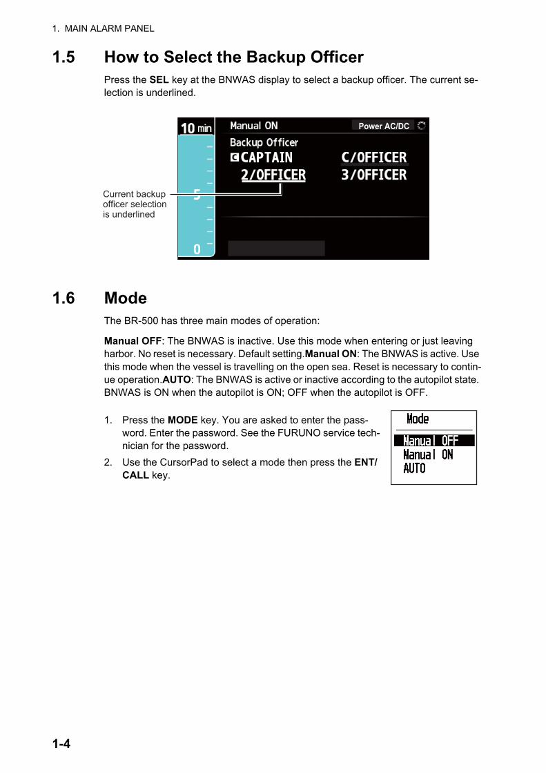
1.5 How to Select the Backup OfficerPress the SEL key at the BNWAS display to select a backup officer. The current se-lection is underlined.
1.6 ModeThe BR-500 has three main modes of operation:
Manual OFF: The BNWAS is inactive. Use this mode when entering or just leaving harbor. No reset is necessary. Default setting.Manual ON: The BNWAS is active. Use this mode when the vessel is travelling on the open sea. Reset is necessary to contin-ue operation.AUTO: The BNWAS is active or inactive according to the autopilot state. BNWAS is ON when the autopilot is ON; OFF when the autopilot is OFF.
1. Press the MODE key. You are asked to enter the pass-word. Enter the password. See the FURUNO service tech-nician for the password.
2. Use the CursorPad to select a mode then press the ENT/CALL key.
Power AC/DCPower AC/DC
Current backupofficer selectionis underlined
1-4
1. MAIN ALARM PANEL
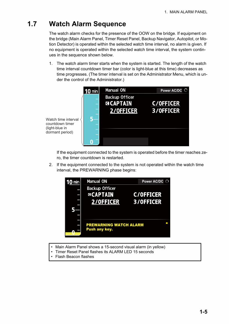
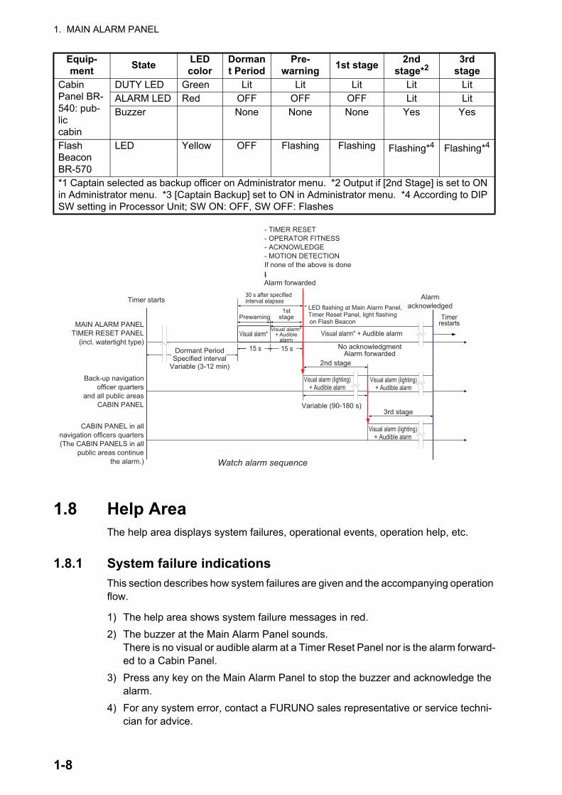
1.7 Watch Alarm SequenceThe watch alarm checks for the presence of the OOW on the bridge. If equipment on the bridge (Main Alarm Panel, Timer Reset Panel, Backup Navigator, Autopilot, or Mo-tion Detector) is operated within the selected watch time interval, no alarm is given. If no equipment is operated within the selected watch time interval, the system contin-ues in the sequence shown below.
1. The watch alarm timer starts when the system is started. The length of the watch time interval countdown timer bar (color is light-blue at this time) decreases as time progresses. (The timer interval is set on the Administrator Menu, which is un-der the control of the Administrator.)
If the equipment connected to the system is operated before the timer reaches ze-ro, the timer countdown is restarted.
2. If the equipment connected to the system is not operated within the watch time interval, the PREWARNING phase begins:
• Main Alarm Panel shows a 15-second visual alarm (in yellow)• Timer Reset Panel flashes its ALARM LED 15 seconds• Flash Beacon flashes
Watch time interval countdown timer(light-blue in dormant period)
Power AC/DC
Power AC/DC
PREWARNING WATCH ALARMPush any key.
1-5
1. MAIN ALARM PANEL
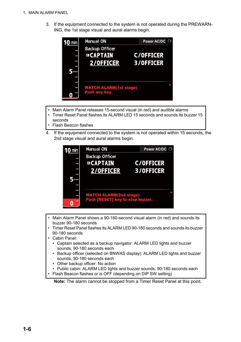
3. If the equipment connected to the system is not operated during the PREWARN-ING, the 1st stage visual and aural alarms begin.
4. If the equipment connected to the system is not operated within 15 seconds, the 2nd stage visual and aural alarms begin.
Note: The alarm cannot be stopped from a Timer Reset Panel at this point.
• Main Alarm Panel releases 15-second visual (in red) and audible alarms• Timer Reset Panel flashes its ALARM LED 15 seconds and sounds its buzzer 15
seconds• Flash Beacon flashes
• Main Alarm Panel shows a 90-180-second visual alarm (in red) and sounds its buzzer 90-180 seconds
• Timer Reset Panel flashes its ALARM LED 90-180 seconds and sounds its buzzer 90-180 seconds
• Cabin Panel:• Captain selected as a backup navigator: ALARM LED lights and buzzer
sounds, 90-180 seconds each• Backup officer (selected on BNWAS display): ALARM LED lights and buzzer
sounds, 90-180 seconds each• Other backup officer: No action• Public cabin: ALARM LED lights and buzzer sounds, 90-180 seconds each
• Flash Beacon flashes or is OFF (depending on DIP SW setting)
Power AC/DC
WATCH ALARM(1st stage)Push any key.
Power AC/DC
WATCH ALARM(2nd stage)Push [RESET] key to stop buzzer.
1-6
1. MAIN ALARM PANEL
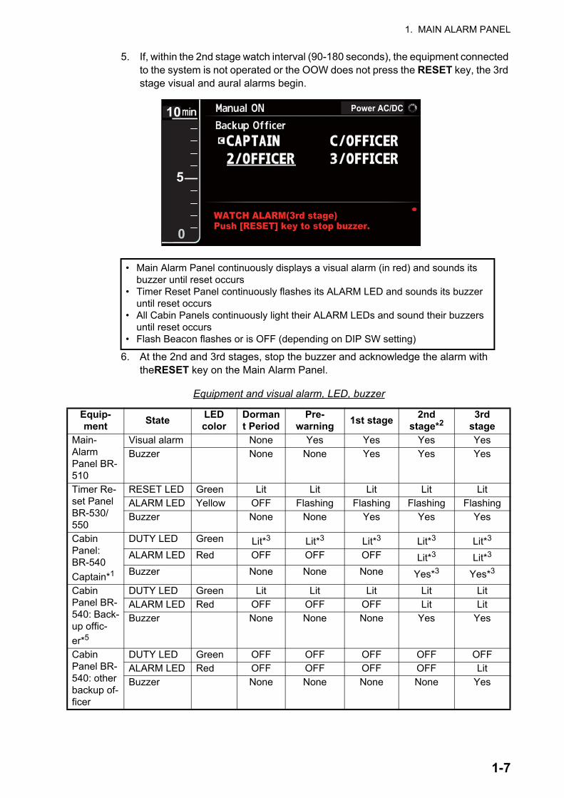
5. If, within the 2nd stage watch interval (90-180 seconds), the equipment connected to the system is not operated or the OOW does not press the RESET key, the 3rd stage visual and aural alarms begin.
6. At the 2nd and 3rd stages, stop the buzzer and acknowledge the alarm with theRESET key on the Main Alarm Panel.
Equipment and visual alarm, LED, buzzer
• Main Alarm Panel continuously displays a visual alarm (in red) and sounds its buzzer until reset occurs
• Timer Reset Panel continuously flashes its ALARM LED and sounds its buzzer until reset occurs
• All Cabin Panels continuously light their ALARM LEDs and sound their buzzers until reset occurs
• Flash Beacon flashes or is OFF (depending on DIP SW setting)
Equip- ment State LED
colorDormant Period
Pre- warning 1st stage 2nd
stage*23rd
stageMain-Alarm Panel BR-510
Visual alarm None Yes Yes Yes YesBuzzer None None Yes Yes Yes
Timer Re-set Panel BR-530/ 550
RESET LED Green Lit Lit Lit Lit LitALARM LED Yellow OFF Flashing Flashing Flashing FlashingBuzzer None None Yes Yes Yes
Cabin Panel: BR-540 Captain*1
DUTY LED Green Lit*3 Lit*3 Lit*3 Lit*3 Lit*3
ALARM LED Red OFF OFF OFF Lit*3 Lit*3
Buzzer None None None Yes*3 Yes*3
Cabin Panel BR-540: Back-up offic-er*5
DUTY LED Green Lit Lit Lit Lit LitALARM LED Red OFF OFF OFF Lit LitBuzzer None None None Yes Yes
Cabin Panel BR-540: other backup of-ficer
DUTY LED Green OFF OFF OFF OFF OFFALARM LED Red OFF OFF OFF OFF LitBuzzer None None None None Yes
Power AC/DC
WATCH ALARM(3rd stage)Push [RESET] key to stop buzzer.
0
10
5
1-7
1. MAIN ALARM PANEL
1.8 Help AreaThe help area displays system failures, operational events, operation help, etc.
1.8.1 System failure indicationsThis section describes how system failures are given and the accompanying operation flow.
1) The help area shows system failure messages in red. 2) The buzzer at the Main Alarm Panel sounds.
There is no visual or audible alarm at a Timer Reset Panel nor is the alarm forward-ed to a Cabin Panel.
3) Press any key on the Main Alarm Panel to stop the buzzer and acknowledge the alarm.
4) For any system error, contact a FURUNO sales representative or service techni-cian for advice.
Cabin Panel BR-540: pub-liccabin
DUTY LED Green Lit Lit Lit Lit LitALARM LED Red OFF OFF OFF Lit LitBuzzer None None None Yes Yes
Flash Beacon BR-570
LED Yellow OFF Flashing Flashing Flashing*4 Flashing*4
*1 Captain selected as backup officer on Administrator menu. *2 Output if [2nd Stage] is set to ON in Administrator menu. *3 [Captain Backup] set to ON in Administrator menu. *4 According to DIP SW setting in Processor Unit; SW ON: OFF, SW OFF: Flashes
Equip- ment State LED
colorDormant Period
Pre- warning 1st stage 2nd
stage*23rd
stage
MAIN ALARM PANELTIMER RESET PANEL
(incl. watertight type)
Back-up navigationofficer quarters
and all public areasCABIN PANEL
Visual alarm* + Audible alarm
Visual alarm (lighting)+ Audible alarm
Visual alarm (lighting)+ Audible alarm
Alarmacknowledged
Timer starts
Variable (90-180 s)
Timerrestarts
2nd stage
3rd stage
15 s 15 sDormant PeriodSpecified interval
Variable (3-12 min)
No acknowledgmentAlarm forwarded
Alarm forwarded
- TIMER RESET- OPERATOR FITNESS- ACKNOWLEDGE- MOTION DETECTIONIf none of the above is done
Visual alarm*Visual alarm*
+ Audiblealarm
Visual alarm (lighting)+ Audible alarm
* LED flashing at Main Alarm Panel, Timer Reset Panel, light flashing on Flash Beacon
1ststage
30 s after specifiedinterval elapses
Prewarning
CABIN PANEL in allnavigation officers quarters(The CABIN PANELS in all
public areas continuethe alarm.) Watch alarm sequence
1-8
1. MAIN ALARM PANEL
The table on the next page shows the system failure messages.
1.8.2 Operational event indicationsWhen an operational event occurs, the Main Alarm Panel shows the related message in red, yellow or white in the help area.
* RESET key not pressed or equipment on bridge is not operated.
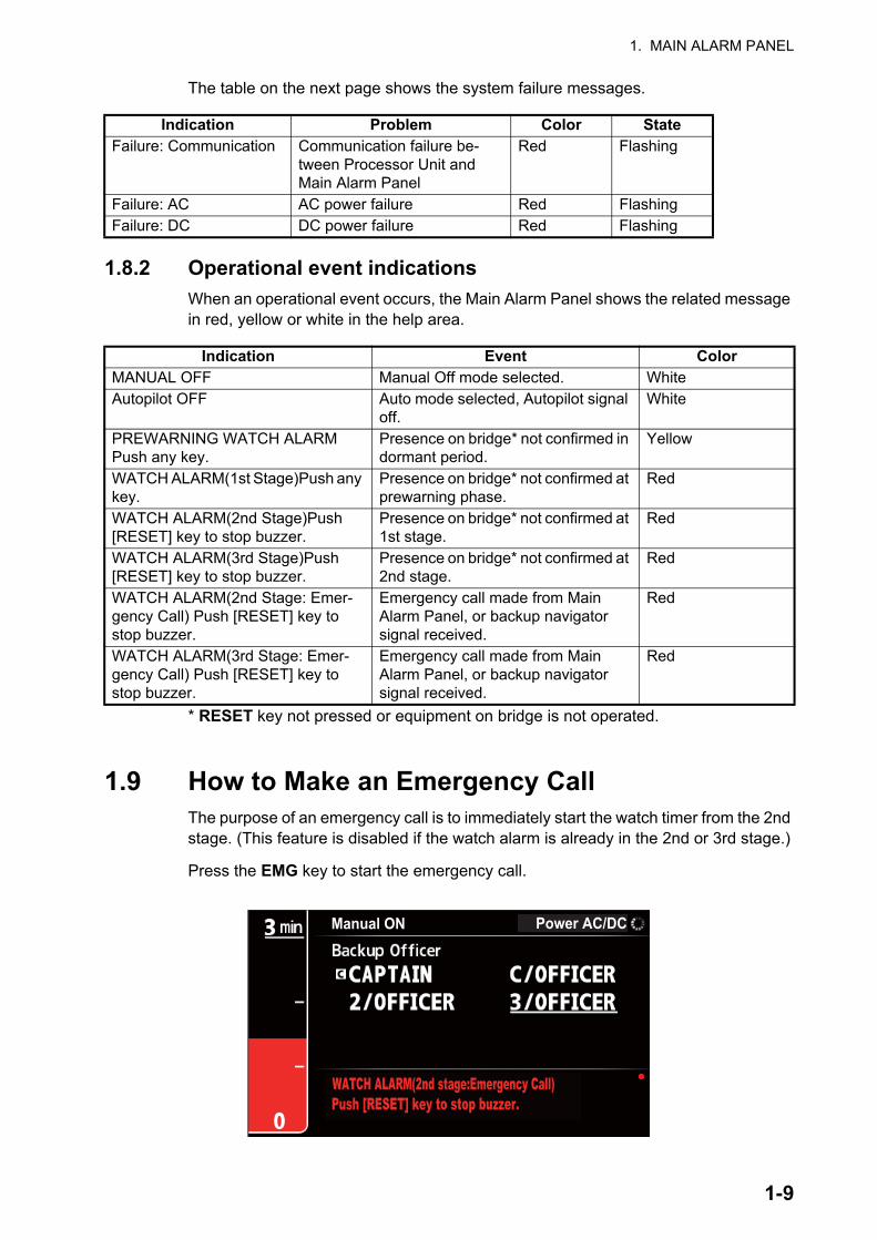
1.9 How to Make an Emergency CallThe purpose of an emergency call is to immediately start the watch timer from the 2nd stage. (This feature is disabled if the watch alarm is already in the 2nd or 3rd stage.)
Press the EMG key to start the emergency call.
Indication Problem Color StateFailure: Communication Communication failure be-
tween Processor Unit and Main Alarm Panel
Red Flashing
Failure: AC AC power failure Red FlashingFailure: DC DC power failure Red Flashing
Indication Event ColorMANUAL OFF Manual Off mode selected. WhiteAutopilot OFF Auto mode selected, Autopilot signal
off.White
PREWARNING WATCH ALARM Push any key.
Presence on bridge* not confirmed in dormant period.
Yellow
WATCH ALARM(1st Stage)Push any key.
Presence on bridge* not confirmed at prewarning phase.
Red
WATCH ALARM(2nd Stage)Push [RESET] key to stop buzzer.
Presence on bridge* not confirmed at 1st stage.
Red
WATCH ALARM(3rd Stage)Push [RESET] key to stop buzzer.
Presence on bridge* not confirmed at 2nd stage.
Red
WATCH ALARM(2nd Stage: Emer-gency Call) Push [RESET] key to stop buzzer.
Emergency call made from Main Alarm Panel, or backup navigator signal received.
Red
WATCH ALARM(3rd Stage: Emer-gency Call) Push [RESET] key to stop buzzer.
Emergency call made from Main Alarm Panel, or backup navigator signal received.
Red
WATCH ALARM(2nd stage:Emergency Call)
Manual ON Power AC/DC
Push [RESET] key to stop buzzer.
1-9
1. MAIN ALARM PANEL
The system goes into the 2nd stage (or 3rd stage depending on system setting). In the 2nd stage, the following occurs:
If the visual and aural alarms are not cancelled at the 2nd stage, the system goes to the 3rd stage and all visual and aural alarms are generated.
To stop the buzzer or cancel the emergency call, press the RESET key on the Main Alarm Panel. The system returns to the dormant state.
1.10 How to Call a Navigation OfficerThe OOW can call the Cabin Panel of the back-up officer. Use the call feature when it is necessary to call a navigation officer to the bridge. This feature is available in all modes. When the watch alarm is generated during a call, the call is cancelled to pro-cess the alarm.
The ALARM LED on the called Cabin Panel lights (red) and the Cabin Panel’s buzzer sounds.
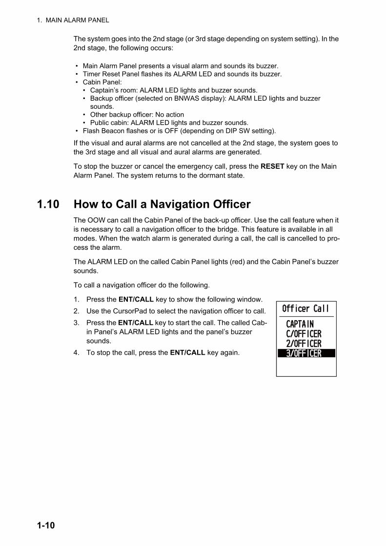
To call a navigation officer do the following.
1. Press the ENT/CALL key to show the following window.2. Use the CursorPad to select the navigation officer to call.3. Press the ENT/CALL key to start the call. The called Cab-
in Panel’s ALARM LED lights and the panel’s buzzer sounds.
4. To stop the call, press the ENT/CALL key again.
• Main Alarm Panel presents a visual alarm and sounds its buzzer.• Timer Reset Panel flashes its ALARM LED and sounds its buzzer.• Cabin Panel:
• Captain’s room: ALARM LED lights and buzzer sounds.• Backup officer (selected on BNWAS display): ALARM LED lights and buzzer
sounds.• Other backup officer: No action• Public cabin: ALARM LED lights and buzzer sounds.
• Flash Beacon flashes or is OFF (depending on DIP SW setting).
1-10
2. OPTIONAL EQUIPMENT
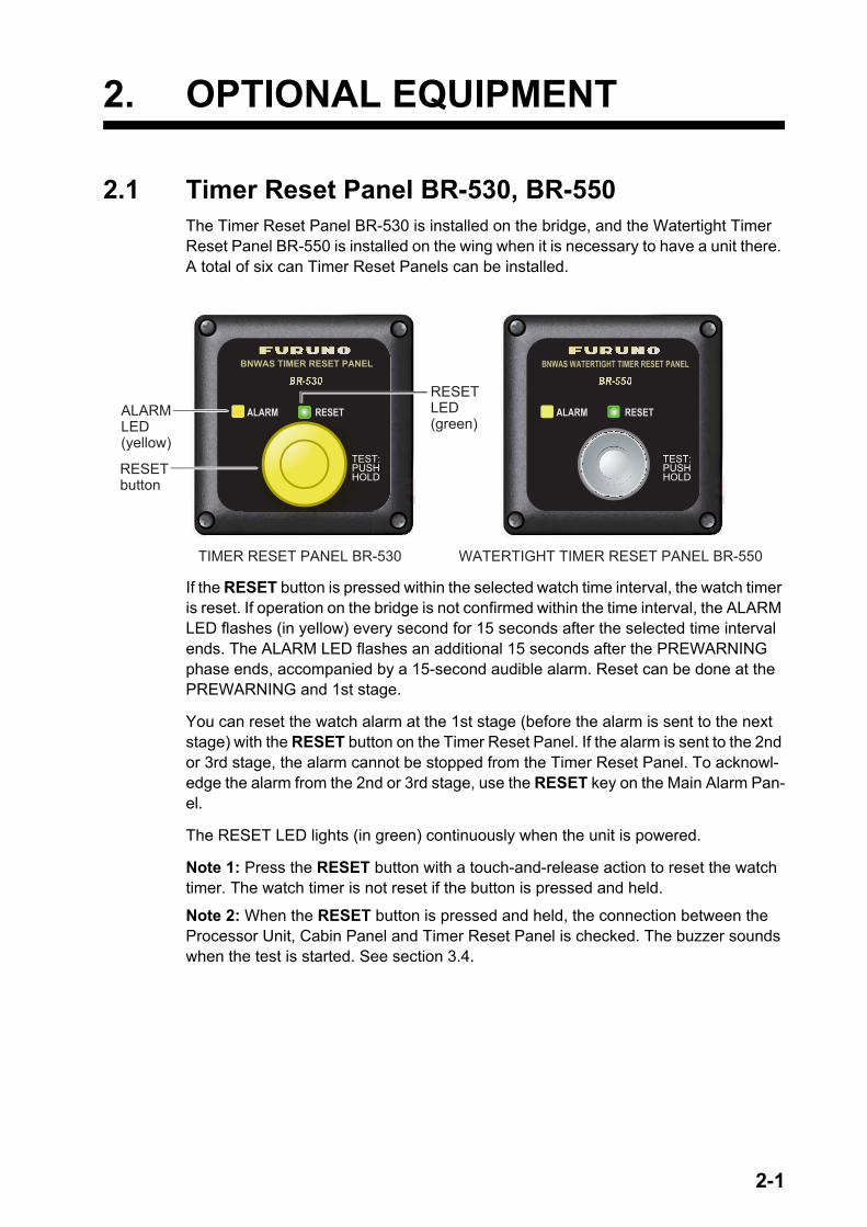
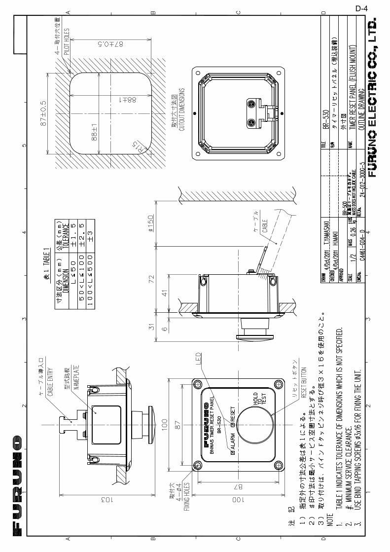
2.1 Timer Reset Panel BR-530, BR-550The Timer Reset Panel BR-530 is installed on the bridge, and the Watertight Timer Reset Panel BR-550 is installed on the wing when it is necessary to have a unit there. A total of six can Timer Reset Panels can be installed.
If the RESET button is pressed within the selected watch time interval, the watch timer is reset. If operation on the bridge is not confirmed within the time interval, the ALARM LED flashes (in yellow) every second for 15 seconds after the selected time interval ends. The ALARM LED flashes an additional 15 seconds after the PREWARNING phase ends, accompanied by a 15-second audible alarm. Reset can be done at the PREWARNING and 1st stage.
You can reset the watch alarm at the 1st stage (before the alarm is sent to the next stage) with the RESET button on the Timer Reset Panel. If the alarm is sent to the 2nd or 3rd stage, the alarm cannot be stopped from the Timer Reset Panel. To acknowl-edge the alarm from the 2nd or 3rd stage, use the RESET key on the Main Alarm Pan-el.
The RESET LED lights (in green) continuously when the unit is powered.
Note 1: Press the RESET button with a touch-and-release action to reset the watch timer. The watch timer is not reset if the button is pressed and held.
Note 2: When the RESET button is pressed and held, the connection between the Processor Unit, Cabin Panel and Timer Reset Panel is checked. The buzzer sounds when the test is started. See section 3.4.
TIMER RESET PANEL BR-530 WATERTIGHT TIMER RESET PANEL BR-550
RESETLED(green)
ALARMLED(yellow)
RESETbutton
2-1
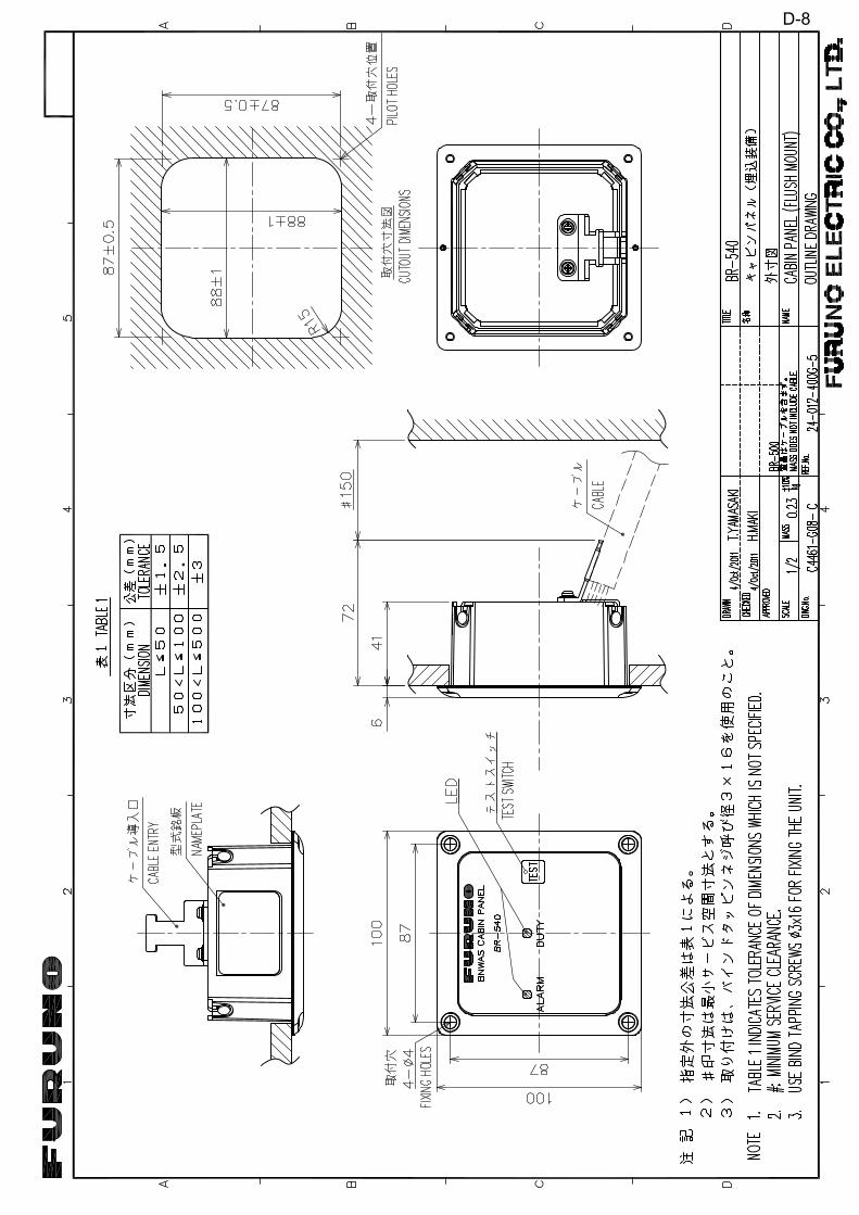
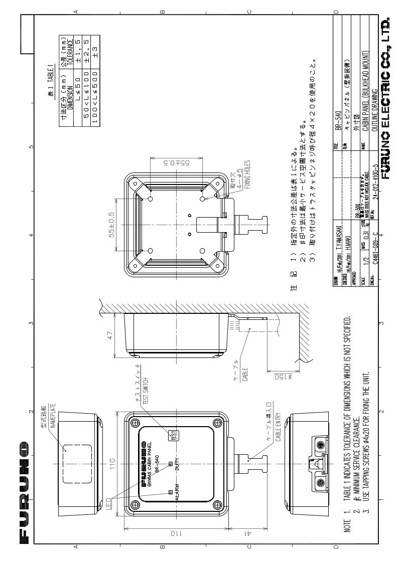
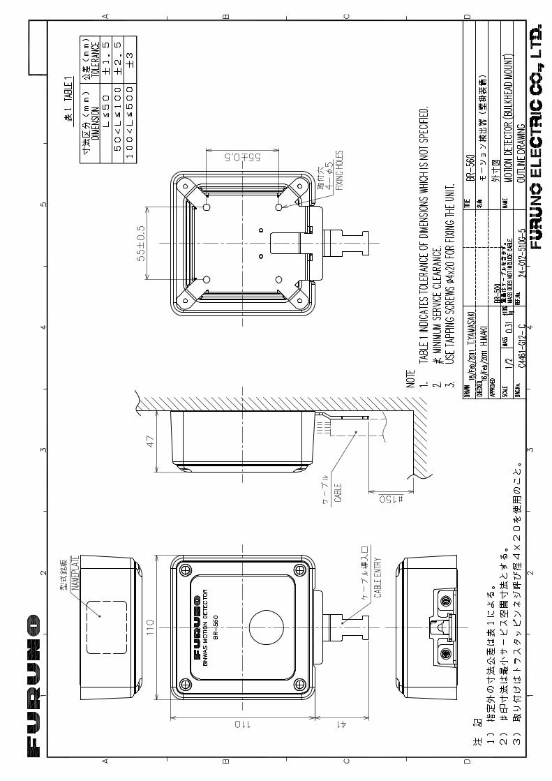
2. OPTIONAL EQUIPMENT
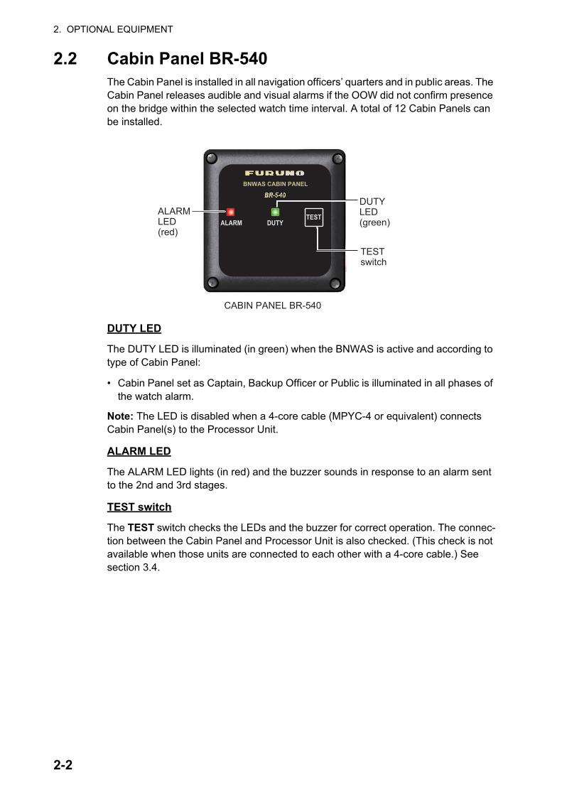
2.2 Cabin Panel BR-540The Cabin Panel is installed in all navigation officers’ quarters and in public areas. The Cabin Panel releases audible and visual alarms if the OOW did not confirm presence on the bridge within the selected watch time interval. A total of 12 Cabin Panels can be installed.
DUTY LED
The DUTY LED is illuminated (in green) when the BNWAS is active and according to type of Cabin Panel:
• Cabin Panel set as Captain, Backup Officer or Public is illuminated in all phases of the watch alarm.
Note: The LED is disabled when a 4-core cable (MPYC-4 or equivalent) connects Cabin Panel(s) to the Processor Unit.
ALARM LED
The ALARM LED lights (in red) and the buzzer sounds in response to an alarm sent to the 2nd and 3rd stages.
TEST switch
The TEST switch checks the LEDs and the buzzer for correct operation. The connec-tion between the Cabin Panel and Processor Unit is also checked. (This check is not available when those units are connected to each other with a 4-core cable.) See section 3.4.
CABIN PANEL BR-540
ALARMLED(red)
TESTswitch
DUTYLED(green)
2-2
2. OPTIONAL EQUIPMENT
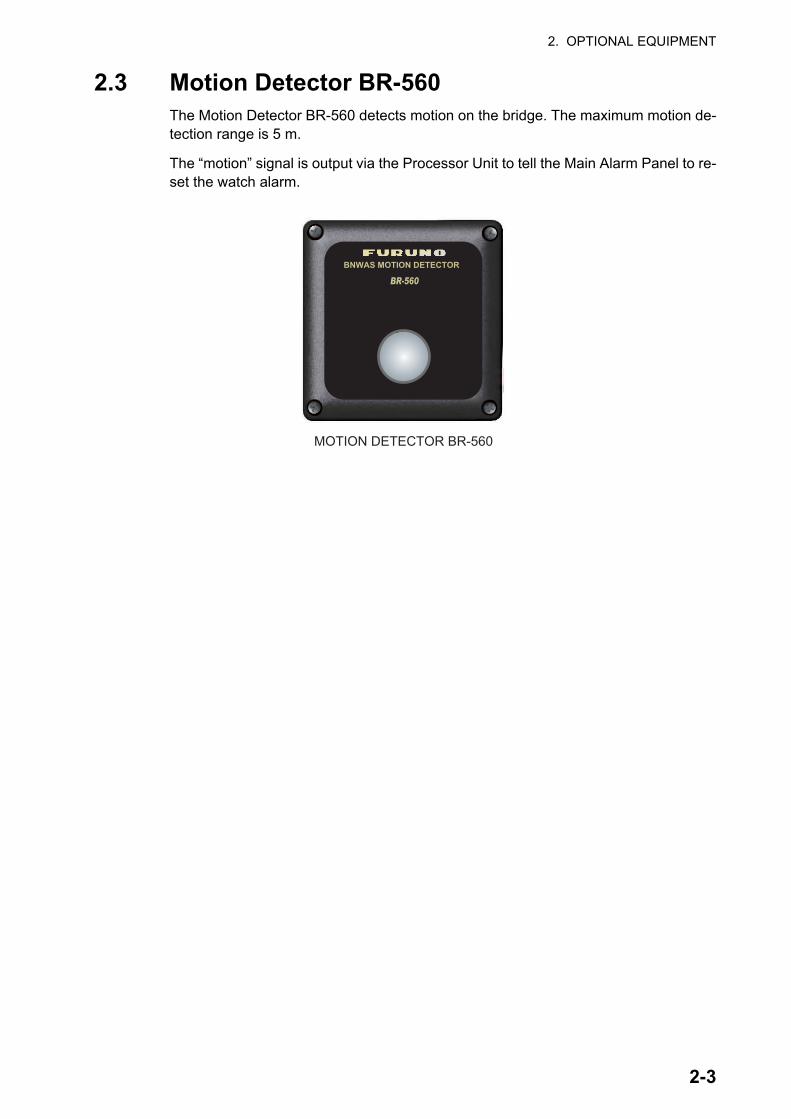
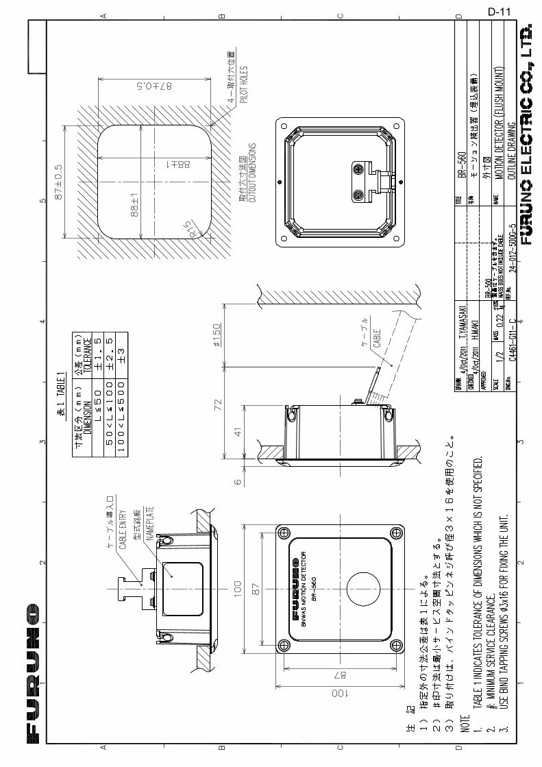
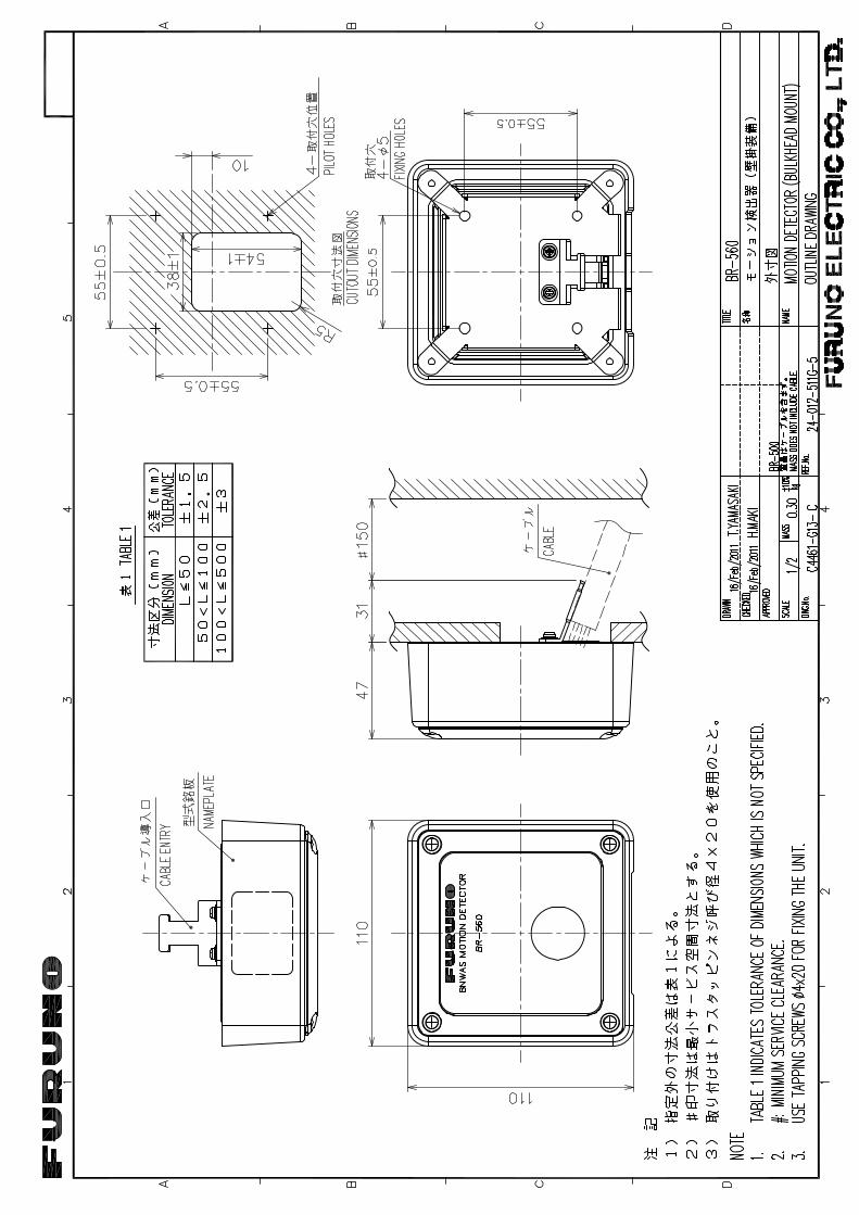
2.3 Motion Detector BR-560The Motion Detector BR-560 detects motion on the bridge. The maximum motion de-tection range is 5 m.
The “motion” signal is output via the Processor Unit to tell the Main Alarm Panel to re-set the watch alarm.
MOTION DETECTOR BR-560
2-3
2. OPTIONAL EQUIPMENT
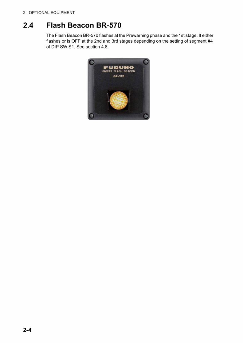
2.4 Flash Beacon BR-570The Flash Beacon BR-570 flashes at the Prewarning phase and the 1st stage. It either flashes or is OFF at the 2nd and 3rd stages depending on the setting of segment #4 of DIP SW S1. See section 4.8.
2-4
3. MAINTENANCE, TROUBLE-SHOOTING
This chapter provides maintenance and troubleshooting procedures for the user and serviceman.
3.1 MaintenanceMaintenance is important to keep the equipment in good working order. Check the items shown in the table monthly.
Item Check point Comments
Cabinet Dust on the cabinets Remove dust with a dry clean cloth. Do not use commercial cleaners to clean the equip-ment. Those cleaners can remove paint and markers.
LCD on Main Alarm Panel
Dust on the LCD Wipe the LCD carefully to prevent scratching, using tissue paper and an LCD cleaner. To re-move dirt or salt deposits, use the LCD clean-er, wiping slowly with tissue paper so as to dissolve the dirt or salt. Change paper fre-quently so the salt or dirt will not scratch the LCD. Do not use solvents such as thinner, ac-etone or benzene for cleaning.
WARNING NOTICEDo not apply paint, anti-corrosivesealant or contact spray to plasticparts or equipment coating.
Those items contain products that candamage plastic parts and equipmentcoating.
ELECTRICAL SHOCK HAZARDDo not open the equipment.
This equipment uses highvoltage that can causeelectrical shock.0nly qualified persons canwork inside the equipment.
3-1
3. MAINTENANCE, TROUBLESHOOTING
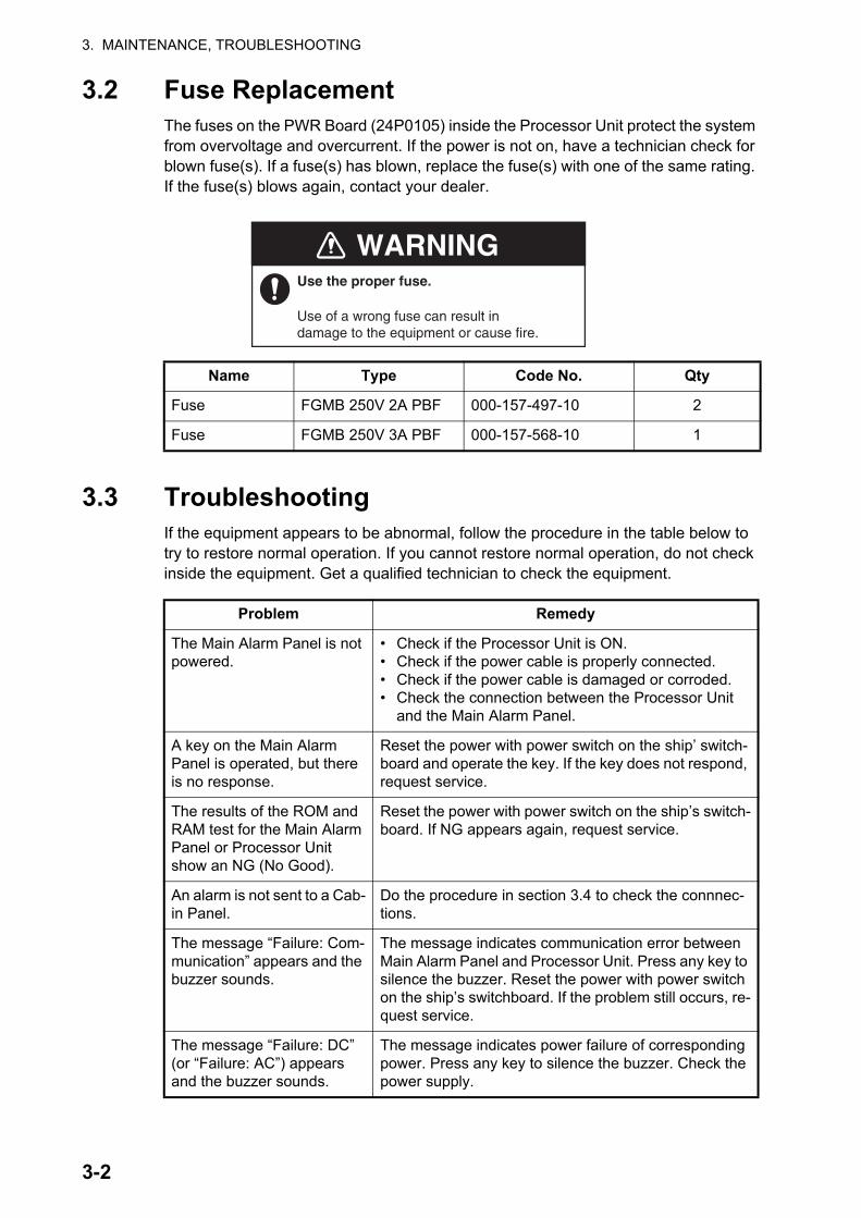
3.2 Fuse ReplacementThe fuses on the PWR Board (24P0105) inside the Processor Unit protect the system from overvoltage and overcurrent. If the power is not on, have a technician check for blown fuse(s). If a fuse(s) has blown, replace the fuse(s) with one of the same rating. If the fuse(s) blows again, contact your dealer.
3.3 TroubleshootingIf the equipment appears to be abnormal, follow the procedure in the table below to try to restore normal operation. If you cannot restore normal operation, do not check inside the equipment. Get a qualified technician to check the equipment.
Name Type Code No. Qty
Fuse FGMB 250V 2A PBF 000-157-497-10 2
Fuse FGMB 250V 3A PBF 000-157-568-10 1
Problem Remedy
The Main Alarm Panel is not powered.
• Check if the Processor Unit is ON.• Check if the power cable is properly connected.• Check if the power cable is damaged or corroded.• Check the connection between the Processor Unit
and the Main Alarm Panel.
A key on the Main Alarm Panel is operated, but there is no response.
Reset the power with power switch on the ship’ switch-board and operate the key. If the key does not respond, request service.
The results of the ROM and RAM test for the Main Alarm Panel or Processor Unit show an NG (No Good).
Reset the power with power switch on the ship’s switch-board. If NG appears again, request service.
An alarm is not sent to a Cab-in Panel.
Do the procedure in section 3.4 to check the connnec-tions.
The message “Failure: Com-munication” appears and the buzzer sounds.
The message indicates communication error between Main Alarm Panel and Processor Unit. Press any key to silence the buzzer. Reset the power with power switch on the ship’s switchboard. If the problem still occurs, re-quest service.
The message “Failure: DC” (or “Failure: AC”) appears and the buzzer sounds.
The message indicates power failure of corresponding power. Press any key to silence the buzzer. Check the power supply.
Use the proper fuse.
Use of a wrong fuse can result indamage to the equipment or cause fire.
WARNING
3-2
3. MAINTENANCE, TROUBLESHOOTING
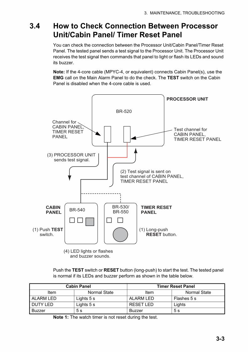
3.4 How to Check Connection Between Processor Unit/Cabin Panel/ Timer Reset PanelYou can check the connection between the Processor Unit/Cabin Panel/Timer Reset Panel. The tested panel sends a test signal to the Processor Unit. The Processor Unit receives the test signal then commands that panel to light or flash its LEDs and sound its buzzer.
Note: If the 4-core cable (MPYC-4, or equivalent) connects Cabin Panel(s), use the EMG call on the Main Alarm Panel to do the check. The TEST switch on the Cabin Panel is disabled when the 4-core cable is used.
Push the TEST switch or RESET button (long-push) to start the test. The tested panel is normal if its LEDs and buzzer perform as shown in the table below.
Note 1: The watch timer is not reset during the test.
Cabin Panel Timer Reset PanelItem Normal State Item Normal State
ALARM LED Lights 5 s ALARM LED Flashes 5 sDUTY LED Lights 5 s RESET LED LightsBuzzer 5 s Buzzer 5 s
(4) LED lights or flashes and buzzer sounds.
PROCESSOR UNIT
CABINPANEL
BR-520
Test channel forCABIN PANEL,TIMER RESET PANEL
(2) Test signal is sent ontest channel of CABIN PANEL,TIMER RESET PANEL
(1) Push TEST switch.
BR-540
Channel forCABIN PANEL,TIMER RESETPANEL
BR-530/BR-550
TIMER RESETPANEL
(1) Long-push RESET button.
(3) PROCESSOR UNIT sends test signal.
3-3

3. MAINTENANCE, TROUBLESHOOTING
Note 2: A Cabin Panel that is currently forwarding an alarm cannot be tested. Howev-er, you can test the Cabin Panels that are not forwarding an alarm. (For example, in the 2nd stage, a Cabin Panel other than the one in the back-up officer’s quarters can be tested.)
3.5 Life Expectancy of Major PartsThe life of the fan depends on the operating environment. It is recommended to re-place the fan before its expected expiration.
Unit Part Type Code No. Approx. LifeProcessor Unit Fan MMF-06G12ES-ROD 000-174-638-10 5 years
3-4
4. INSTALLATION
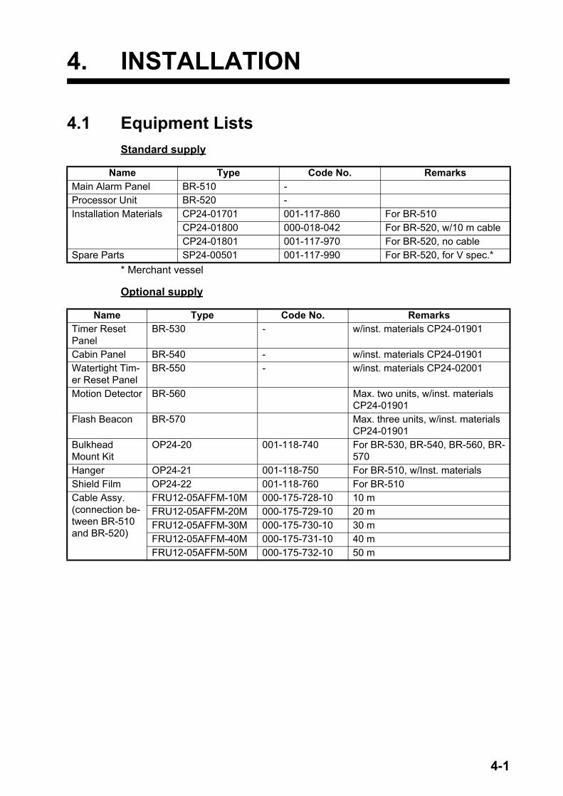
4.1 Equipment ListsStandard supply
* Merchant vessel
Optional supply
Name Type Code No. RemarksMain Alarm Panel BR-510 -Processor Unit BR-520 -Installation Materials CP24-01701 001-117-860 For BR-510
CP24-01800 000-018-042 For BR-520, w/10 m cableCP24-01801 001-117-970 For BR-520, no cable
Spare Parts SP24-00501 001-117-990 For BR-520, for V spec.*
Name Type Code No. RemarksTimer Reset Panel
BR-530 - w/inst. materials CP24-01901
Cabin Panel BR-540 - w/inst. materials CP24-01901Watertight Tim-er Reset Panel
BR-550 - w/inst. materials CP24-02001
Motion Detector BR-560 Max. two units, w/inst. materials CP24-01901
Flash Beacon BR-570 Max. three units, w/inst. materials CP24-01901
Bulkhead Mount Kit
OP24-20 001-118-740 For BR-530, BR-540, BR-560, BR-570
Hanger OP24-21 001-118-750 For BR-510, w/Inst. materialsShield Film OP24-22 001-118-760 For BR-510Cable Assy. (connection be-tween BR-510 and BR-520)
FRU12-05AFFM-10M 000-175-728-10 10 mFRU12-05AFFM-20M 000-175-729-10 20 mFRU12-05AFFM-30M 000-175-730-10 30 mFRU12-05AFFM-40M 000-175-731-10 40 mFRU12-05AFFM-50M 000-175-732-10 50 m
4-1
4. INSTALLATION
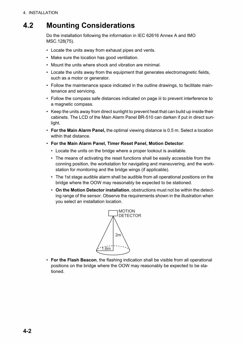
4.2 Mounting ConsiderationsDo the installation following the information in IEC 62616 Annex A and IMO MSC.128(75).
• Locate the units away from exhaust pipes and vents.• Make sure the location has good ventilation.• Mount the units where shock and vibration are minimal.• Locate the units away from the equipment that generates electromagnetic fields,
such as a motor or generator.• Follow the maintenance space indicated in the outline drawings, to facilitate main-
tenance and servicing.• Follow the compass safe distances indicated on page iii to prevent interference to
a magnetic compass.• Keep the units away from direct sunlight to prevent heat that can build up inside their
cabinets. The LCD of the Main Alarm Panel BR-510 can darken if put in direct sun-light.
• For the Main Alarm Panel, the optimal viewing distance is 0.5 m. Select a location within that distance.
• For the Main Alarm Panel, Timer Reset Panel, Motion Detector:• Locate the units on the bridge where a proper lookout is available.• The means of activating the reset functions shall be easily accessible from the
conning position, the workstation for navigating and maneuvering, and the work-station for monitoring and the bridge wings (if applicable).
• The 1st stage audible alarm shall be audible from all operational positions on the bridge where the OOW may reasonably be expected to be stationed.
• On the Motion Detector installation, obstructions must not be within the detect-ing range of the sensor. Observe the requirements shown in the illustration when you select an installation location.
• For the Flash Beacon, the flashing indication shall be visible from all operational positions on the bridge where the OOW may reasonably be expected to be sta-tioned.
MOTIONDETECTOR
2m
1.6m
4-2
4. INSTALLATION
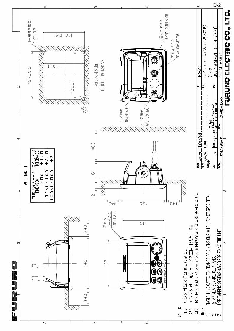
4.3 Main Alarm Panel BR-510The Main Alarm Panel can be mounted on a desktop or flush mounted in a console, on the bridge. Follow the mounting considerations in section 4.2 to select a location. Additionally, the unit must be located on the bridge where a proper look out is provid-ed.
4.3.1 Desktop mountThis mounting method requires the optional hanger.
1. Unscrew knobs to remove the unit from the hanger.
2. Make four pilot holes (for 5x20 self-tap-ping screws) in the mounting location.
3. Fix the hanger to the mounting location with four self-tapping screws (5×20, supplied).
4. Attach cables to the back of the unit (see section 4.7.3).
5. Set the unit to the hanger, and fasten knobs to fix the unit.
4.3.2 Flush mount1. Use the template (supplied) to make a hole in the mounting location.2. Prepare four pilot holes (for 3×20 self-tapping screws) at the mounting location.3. Remove the front panel from the unit by unfastening the catches at the rear of the
panel.4. Set the F mount cushion (supplied) to the hole made at step 1.5. Connect cables to the unit. (See section 4.7.3).6. Use four self-tapping screws (3x20, supplied) to fasten the unit to the mounting
location then re-attach the front panel.
MAIN ALARM PANEL
Self-tapping Screw(5x20, 4 pcs.)
Knob
Hanger
MountingHole
F MountCushion
MAIN ALARMPANEL
Self-tapping Screw(3x20, 4 pcs.)
Front Panel
4-3
4. INSTALLATION
4.3.3 Shield film (option)If the screen is too bright with minimum bril-liance at nighttime, install the shield film to re-duce the brilliance.
1. Clean the LCD with an LCD cleaning cloth.
2. Peel off the protective backing from the shield film.
3. Set the top edge of the shield film to the top edge of the panel and slowly attach the film.
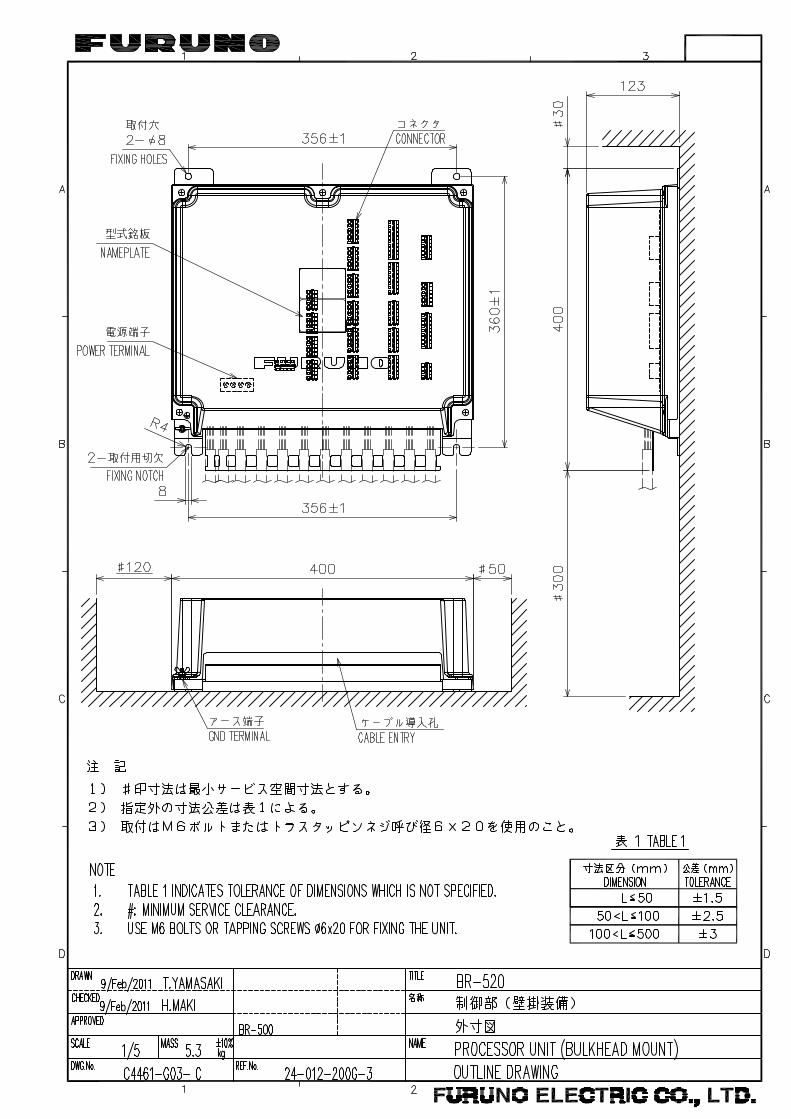
4.4 Processor Unit BR-520The Processor Unit is designed to be mounted on a bulkhead or the deck. Follow the mounting considerations in section 4.2 when selecting a location.
Refer to the outline drawing at the back of this manual for dimensions. Fasten the unit with M6 bolts or 6×20 self-tapping screws. (Supply bolts locally.)
4.5 Timer Reset Panel BR-530, Cabin Panel BR-540, Motion Detector BR-560, Flash Beacon BR-570 (optional units)These units can be flush mounted in a panel, or fixed to a bulkhead. Follow the mount-ing considerations in section 4.2 when selecting a location.
4.5.1 Flush mount Prepare a cutout in the location, referring to the outline drawings. Connect the signal cable to the unit BEFORE you install the unit. (See section 4.7.4.) Set the unit to the cutout and fasten the unit with four 3×16 self-tapping screws (supplied).
Name Type Code No. Qty Remarks
Self-tapping Screw 3×16 SUS304 000-171-996-10 4
Cable Tie CV-150B 000-167-183-10 5
SHIELD FILM
4-4
4. INSTALLATION
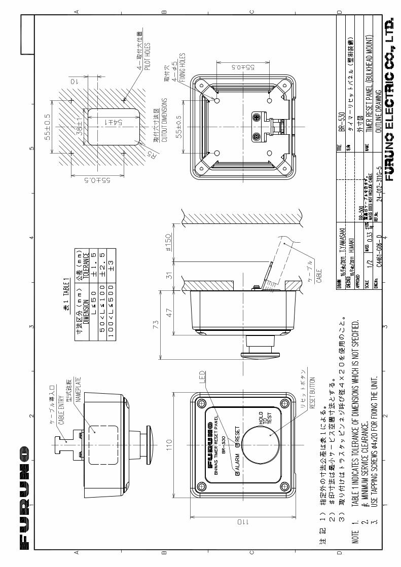
4.5.2 Bulkhead mount (option)This mounting method requires the optional bulkhead mount kit (Type: OP24-20, Code No. 001-118-740-00), the contents of which are shown in the table below. The cable can be led into the unit from the bottom or rear of the unit.
Lead in the cable from the rear of the unit
1. Prepare a cutout in the mounting location, referring to the outline drawing.
2. Pass the cable through the cutout and the Mount Case and connect it to the ter-minal on the Chassis.
3. Remove the Clamp from the bottom of the Mount Base. Remove the cable protec-tor from the clamp and attach it to the supplied clamp. Attach the supplied Clamp to the rear cover with the same screws. (You may discard the clamp originally at-tached to the Mount Base.)
Name Type Code No. Qty Remarks
Mount Case 24-012-3101-0 100-362-890-10 1
Mount Base 24-012-3102-1 100-362-901-10 1
Clamp 24-012-3103-0 100-362-910-10 1
Self-tapping Screw 4×20 SUS304 000-158-850-10 4
Binding Screw M3×8 SUS304 000-172-166-10 4
Mount Case
Chassis
Mount Base
Clamp
Cable Protector
4-5
4. INSTALLATION
4. Fasten the cable to the Clamp with a cable tie (local supply). As shown in the fig-ure below, make the distance between the terminal and the cable tie 100 mm.
5. Fasten the Mount Base to the mounting location with four self-tapping screws (supplied). Fasten the Chassis to the Mount Case with four binding screws (sup-plied).
6. Seal the bottom entry with the blind sheet supplied.
Self-tapping screws Binding screws
Mount case
Blind sheet
15±5mm
4-6
4. INSTALLATION
Lead in the cable from the bottom of the unit
1. Fasten Cable Clamp 2 to the Mount Base.
2. Fasten the Mount Base/Clamp to the mounting location with four self-tapping screws (supplied).
3. Pass the signal cable through the Mount Case.
4. Connect the signal cable to the WAGO terminal block. See the interconnection di-agram.
Mount Base
Clamp
4-7
4. INSTALLATION
5. Set the Chassis to the Mount Base. Set the signal cable in the notch in the Clamp.
6. Fasten the Chassis to the Mount Case with binding screws (supplied)
7. Fasten the signal cable to the Clamp with a cable tie.
Cable Tie
4-8
4. INSTALLATION
4.6 Watertight Timer Reset Panel BR-550 (option)Follow the mounting considerations in section 4.2 when selecting a location. Refer to the outline drawing at the back of this manual for dimensions.
1. Pass the signal cable through the gland and then the Nut of the Waterproof Case. Pass the cable into the unit. Process the cable as shown on page 4-13.
2. Connect the signal cable to the WAGO terminal block on the Chassis. See the in-terconnection diagram.
3. A gasket is fitted on the Chassis. Confirm that the gasket is correctly seated. If not correctly seated, re-seat the gasket, referring to the illustration below for the in-serting direction.
4. Fasten the Chassis to the Waterproof Case with the screws supplied. Do not use other types of screws; watertight integrity cannot be guaranteed.
Insertingdirection
Gasket
4-9
4. INSTALLATION
5. Tighten the nut.
6. Fasten the unit to the mounting location with the supplied self-tapping screws (6×30, Code No. 000-162-614-10).
4-10
4. INSTALLATION
4.7 Wiring
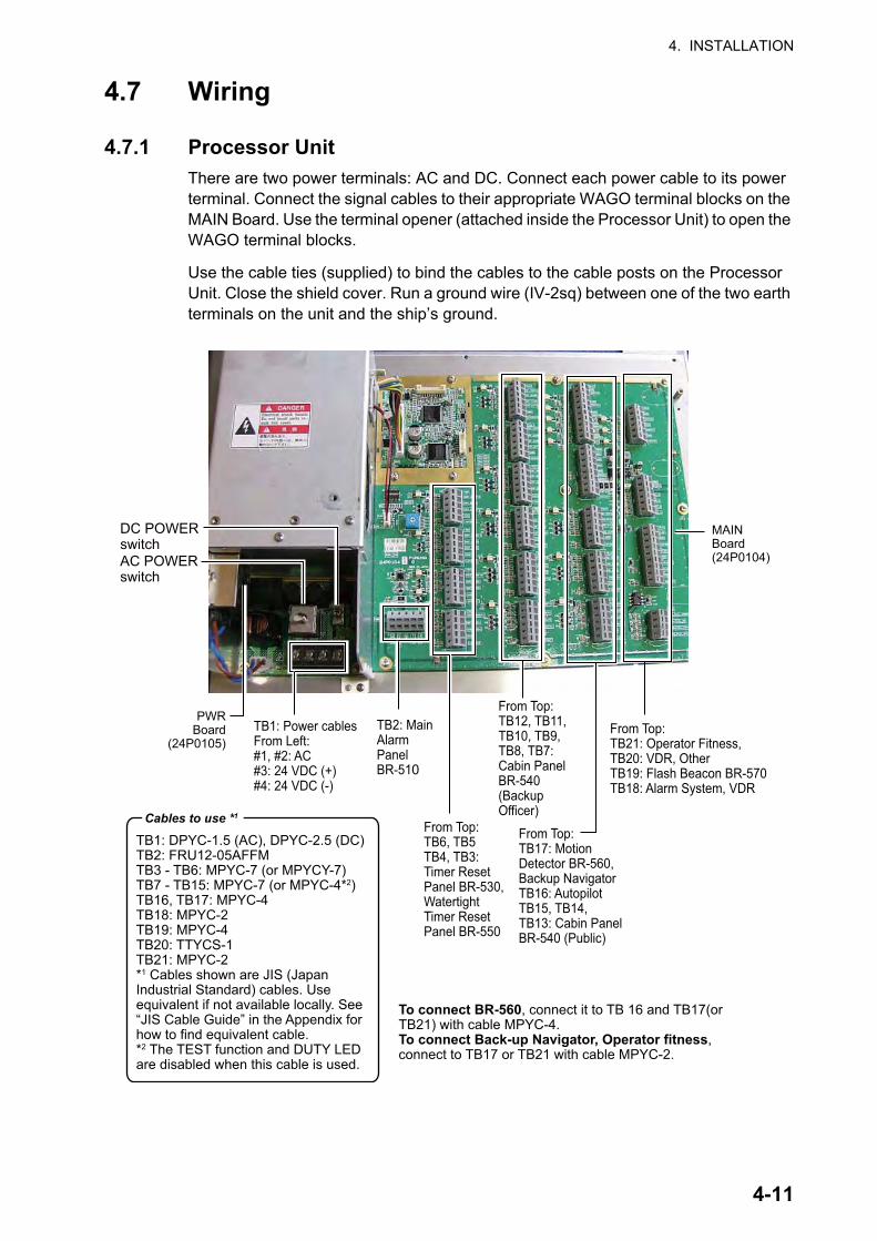
4.7.1 Processor UnitThere are two power terminals: AC and DC. Connect each power cable to its power terminal. Connect the signal cables to their appropriate WAGO terminal blocks on the MAIN Board. Use the terminal opener (attached inside the Processor Unit) to open the WAGO terminal blocks.
Use the cable ties (supplied) to bind the cables to the cable posts on the Processor Unit. Close the shield cover. Run a ground wire (IV-2sq) between one of the two earth terminals on the unit and the ship’s ground.
TB1: DPYC-1.5 (AC), DPYC-2.5 (DC)TB2: FRU12-05AFFM TB3 - TB6: MPYC-7 (or MPYCY-7)TB7 - TB15: MPYC-7 (or MPYC-4*2)TB16, TB17: MPYC-4 TB18: MPYC-2TB19: MPYC-4 TB20: TTYCS-1TB21: MPYC-2*1 Cables shown are JIS (Japan Industrial Standard) cables. Use equivalent if not available locally. See “JIS Cable Guide” in the Appendix for how to find equivalent cable.*2 The TEST function and DUTY LED are disabled when this cable is used.
TB2: MainAlarmPanelBR-510
From Top:TB6, TB5TB4, TB3: Timer ResetPanel BR-530,Watertight Timer Reset Panel BR-550
From Top:TB12, TB11,TB10, TB9,TB8, TB7:Cabin Panel BR-540(Backup Officer)
From Top:TB17: Motion Detector BR-560, Backup NavigatorTB16: AutopilotTB15, TB14,TB13: Cabin Panel BR-540 (Public)
From Top:TB21: Operator Fitness,TB20: VDR, OtherTB19: Flash Beacon BR-570TB18: Alarm System, VDR
Cables to use *1
TB1: Power cablesFrom Left:#1, #2: AC#3: 24 VDC (+)#4: 24 VDC (-)
PWRBoard
(24P0105)
MAINBoard(24P0104)AC POWER
switch
DC POWER switch
To connect BR-560, connect it to TB 16 and TB17(or TB21) with cable MPYC-4.To connect Back-up Navigator, Operator fitness,connect to TB17 or TB21 with cable MPYC-2.
4-11
4. INSTALLATION
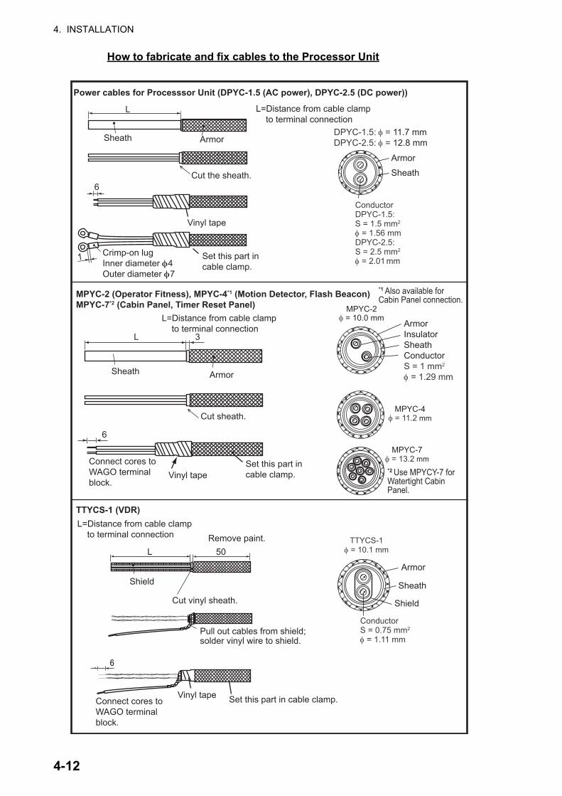
How to fabricate and fix cables to the Processor Unit
L 3
L=Distance from cable clamp to terminal connection
ArmorSheath
Cut sheath.
6
Connect cores toWAGO terminalblock.
MPYC-2φ = 10.0 mm
ArmorInsulatorSheathConductorS = 1 mm2
φ = 1.29 mm
MPYC-4φ = 11.2 mm
MPYC-7φ = 13.2 mm
DPYC-1.5: φ = 11.7 mmDPYC-2.5: φ = 12.8 mm
Armor
Sheath
ConductorDPYC-1.5:S = 1.5 mm2
φ = 1.56 mmDPYC-2.5:S = 2.5 mm2
φ = 2.01 mm
L=Distance from cable clamp to terminal connection
L=Distance from cable clamp to terminal connection Remove paint.
L 50
Shield
Cut vinyl sheath.
Pull out cables from shield;solder vinyl wire to shield.
Vinyl tape Set this part in cable clamp.
TTYCS-1φ = 10.1 mm
Armor
Sheath
Shield
ConductorS = 0.75 mm2
φ = 1.11 mm
Power cables for Processsor Unit (DPYC-1.5 (AC power), DPYC-2.5 (DC power))
MPYC-2 (Operator Fitness), MPYC-4*1 (Motion Detector, Flash Beacon) MPYC-7*2 (Cabin Panel, Timer Reset Panel)
TTYCS-1 (VDR)
Crimp-on lugInner diameter φ4Outer diameter φ7
Set this part incable clamp.
Connect cores toWAGO terminalblock.
*1 Also available for Cabin Panel connection.
*2 Use MPYCY-7 for Watertight CabinPanel.
Vinyl tapeSet this part incable clamp.
L
6
Armor
Cut the sheath.
Vinyl tape
Sheath
1
4-12
4. INSTALLATION
4.7.2 Wiring informationItem Description
Operator fitness • FAR-2105: It is not possible to create a connection for operator fitness between FAR-2105 and the Processor Unit, because the FAR-2105 does not have operator fitness output.
• FAR-2107: Use port J612 (pin #7/8 for operator fitness), where a con-tact signal is available.
• Other makes of radars: Check for availability of contact signal.FRU12-05AFFM(between BR-510 andBR-520)
This cable is fit with a Micro-C connector (male) on one end and a stripped end for connection to the BR-520. The standard length is 6 m. 10 m, 20 m, 30 m, 40 m, and 50 m cables are optionally available.
Cable MPYC-7(between BR-530/550 and BR-520)
40 m and the total length for all units is max. 150 m. For example, when four BR-530 are installed: No.1 BR-530: 40 m No. 2 BR-530: 40 m No. 3 BR-530: 40 m No. 4 BR-530: 30 m Total length: 150 m
Motion DetectorBR-560
• Pyroelectric detection• Detection range: Up to 5m, 80°×80°• Detection rate: 0.8 thru 1.2 m/s• Detection sensitivity: 4°C (difference from surround in temperature)Generally, up to two Motion Detectors can be installed, at INPUT3/4 and INPUT5-8. Also, INPUT port 2 can be used by setting [INPUT2] on the Ser-vice menu to [Timer Reset].
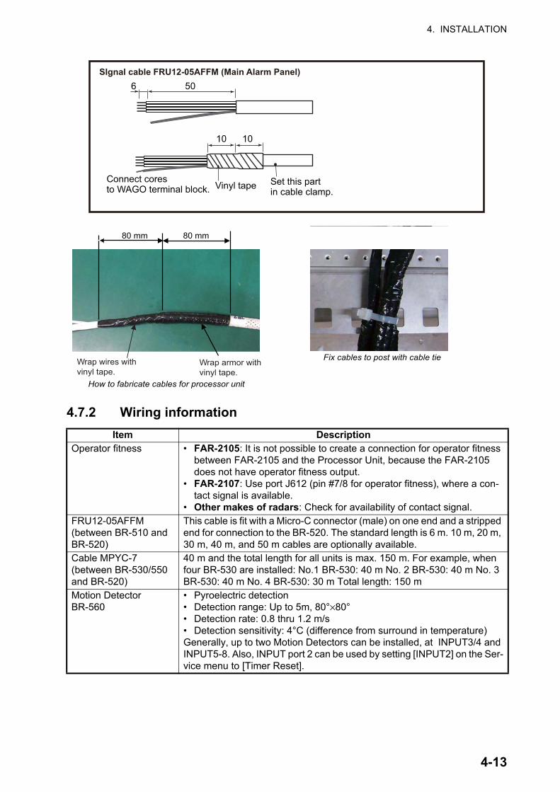
506
10 10
Connect coresto WAGO terminal block. Vinyl tape Set this part
in cable clamp.
SIgnal cable FRU12-05AFFM (Main Alarm Panel)
80 mm 80 mm
Fix cables to post with cable tieWrap wires withvinyl tape.
Wrap armor withvinyl tape.
How to fabricate cables for processor unit
4-13
4. INSTALLATION
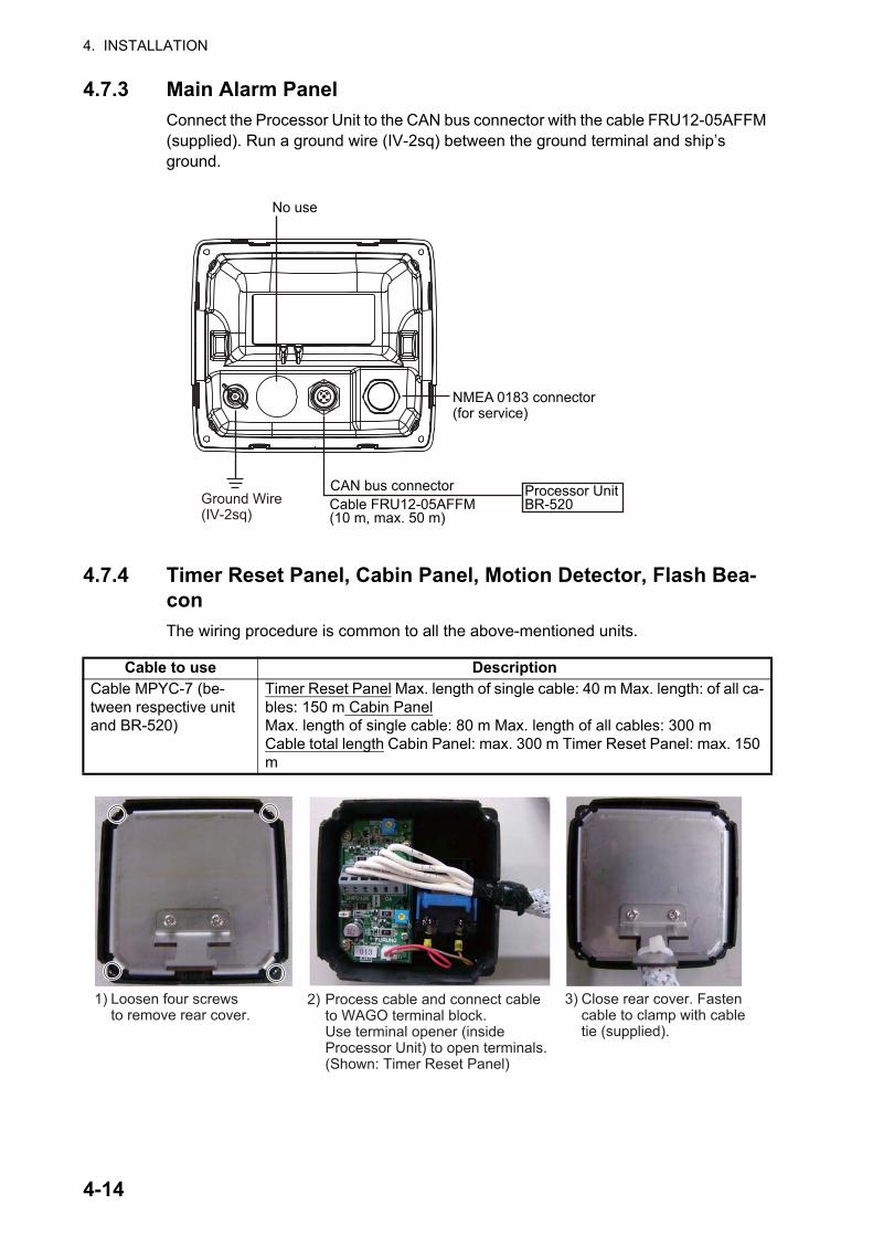
4.7.3 Main Alarm PanelConnect the Processor Unit to the CAN bus connector with the cable FRU12-05AFFM (supplied). Run a ground wire (IV-2sq) between the ground terminal and ship’s ground.
4.7.4 Timer Reset Panel, Cabin Panel, Motion Detector, Flash Bea-conThe wiring procedure is common to all the above-mentioned units.
Cable to use DescriptionCable MPYC-7 (be-tween respective unit and BR-520)
Timer Reset Panel Max. length of single cable: 40 m Max. length: of all ca-bles: 150 m Cabin PanelMax. length of single cable: 80 m Max. length of all cables: 300 mCable total length Cabin Panel: max. 300 m Timer Reset Panel: max. 150 m
Ground Wire(IV-2sq)
Cable FRU12-05AFFM(10 m, max. 50 m)
Processor Unit BR-520
CAN bus connector
No use
NMEA 0183 connector(for service)
1) Loosen four screws to remove rear cover.
2) Process cable and connect cable to WAGO terminal block. Use terminal opener (inside Processor Unit) to open terminals. (Shown: Timer Reset Panel)
3) Close rear cover. Fasten cable to clamp with cable tie (supplied).
4-14
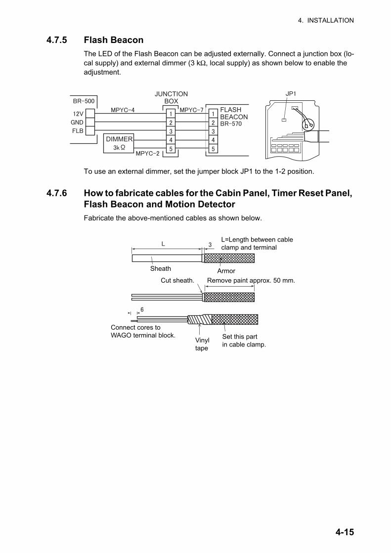
4. INSTALLATION
4.7.5 Flash BeaconThe LED of the Flash Beacon can be adjusted externally. Connect a junction box (lo-cal supply) and external dimmer (3 kΩ, local supply) as shown below to enable the adjustment.
To use an external dimmer, set the jumper block JP1 to the 1-2 position.
4.7.6 How to fabricate cables for the Cabin Panel, Timer Reset Panel, Flash Beacon and Motion DetectorFabricate the above-mentioned cables as shown below.
JUNCTIONBOX
FLASHBEACON
DIMMER
L=Length between cableclamp and terminal
Sheath ArmorCut sheath. Remove paint approx. 50 mm.
Vinyltape
Set this partin cable clamp.
Connect cores toWAGO terminal block.
4-15
4. INSTALLATION
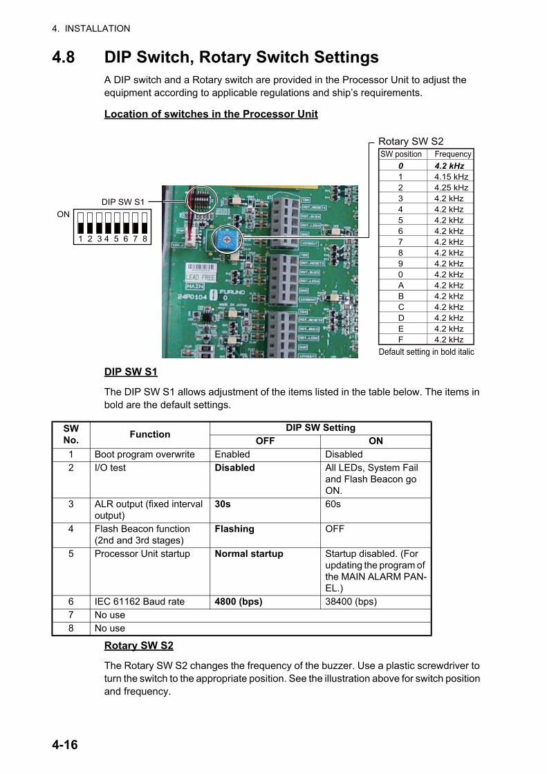
4.8 DIP Switch, Rotary Switch SettingsA DIP switch and a Rotary switch are provided in the Processor Unit to adjust the equipment according to applicable regulations and ship’s requirements.
Location of switches in the Processor Unit
DIP SW S1
The DIP SW S1 allows adjustment of the items listed in the table below. The items in bold are the default settings.
Rotary SW S2
The Rotary SW S2 changes the frequency of the buzzer. Use a plastic screwdriver to turn the switch to the appropriate position. See the illustration above for switch position and frequency.
SW No. Function DIP SW Setting
OFF ON1 Boot program overwrite Enabled Disabled2 I/O test Disabled All LEDs, System Fail
and Flash Beacon go ON.
3 ALR output (fixed interval output)
30s 60s
4 Flash Beacon function (2nd and 3rd stages)
Flashing OFF
5 Processor Unit startup Normal startup Startup disabled. (For updating the program of the MAIN ALARM PAN-EL.)
6 IEC 61162 Baud rate 4800 (bps) 38400 (bps)7 No use8 No use
0 4.2 kHz1 4.15 kHz2 4.25 kHz3 4.2 kHz4 4.2 kHz5 4.2 kHz6 4.2 kHz7 4.2 kHz8 4.2 kHz9 4.2 kHz0 4.2 kHzA 4.2 kHzB 4.2 kHzC 4.2 kHzD 4.2 kHzE 4.2 kHzF 4.2 kHz
SW position FrequencyRotary SW S2
Default setting in bold italic
DIP SW S1ON
1 2 3 4 5 6 7 8
4-16
4. INSTALLATION
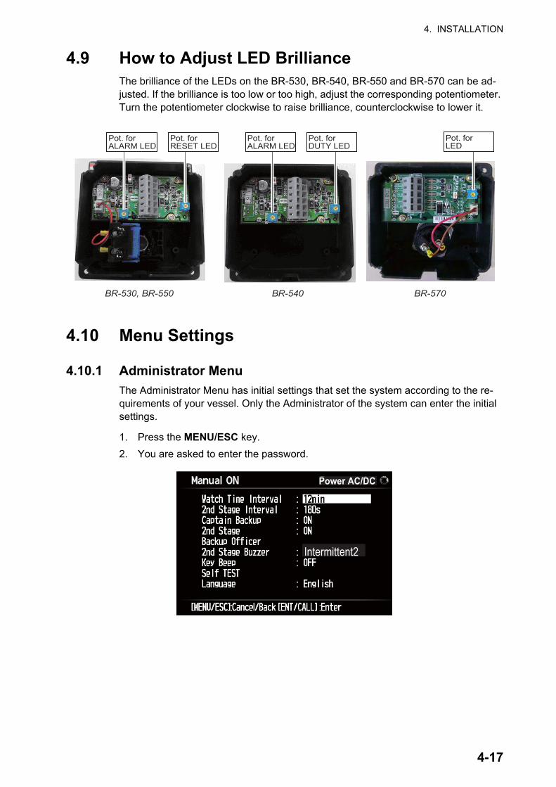
4.9 How to Adjust LED BrillianceThe brilliance of the LEDs on the BR-530, BR-540, BR-550 and BR-570 can be ad-justed. If the brilliance is too low or too high, adjust the corresponding potentiometer. Turn the potentiometer clockwise to raise brilliance, counterclockwise to lower it.
4.10 Menu Settings
4.10.1 Administrator MenuThe Administrator Menu has initial settings that set the system according to the re-quirements of your vessel. Only the Administrator of the system can enter the initial settings.
1. Press the MENU/ESC key. 2. You are asked to enter the password.
BR-530, BR-550 BR-540
Pot. forALARM LED
Pot. forRESET LED
Pot. forALARM LED
Pot. forDUTY LED
Pot. forLED
BR-570
Power AC/DC
Intermittent2
4-17
4. INSTALLATION
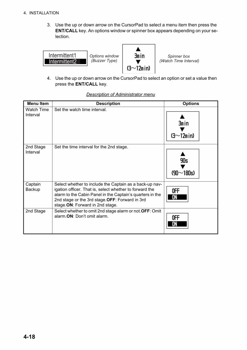
3. Use the up or down arrow on the CursorPad to select a menu item then press the ENT/CALL key. An options window or spinner box appears depending on your se-lection.
4. Use the up or down arrow on the CursorPad to select an option or set a value then press the ENT/CALL key.
Description of Administrator menu
Menu Item Description OptionsWatch Time Interval
Set the watch time interval.
2nd Stage Interval
Set the time interval for the 2nd stage.
Captain Backup
Select whether to include the Captain as a back-up nav-igation officer. That is, select whether to forward the alarm to the Cabin Panel in the Captain’s quarters in the 2nd stage or the 3rd stage.OFF: Forward in 3rd stage.ON: Forward in 2nd stage.
2nd Stage Select whether to omit 2nd stage alarm or not.OFF: Omit alarm.ON: Don’t omit alarm.
Intermittent2Intermittent1 Spinner box
(Watch Time Interval)
Options window(Buzzer Type)
4-18
4. INSTALLATION
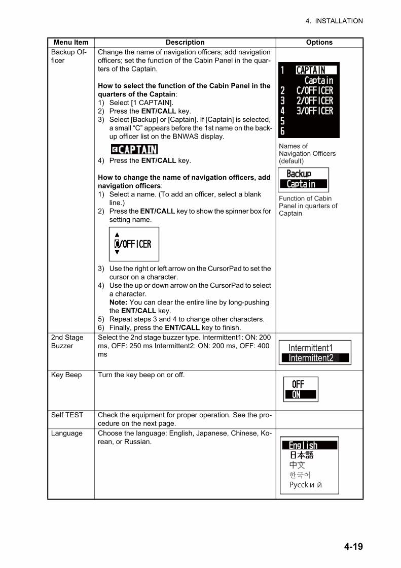
Backup Of-ficer
Change the name of navigation officers; add navigation officers; set the function of the Cabin Panel in the quar-ters of the Captain.
How to select the function of the Cabin Panel in the quarters of the Captain:1) Select [1 CAPTAIN].2) Press the ENT/CALL key.3) Select [Backup] or [Captain]. If [Captain] is selected,
a small “C” appears before the 1st name on the back-up officer list on the BNWAS display.
4) Press the ENT/CALL key.
How to change the name of navigation officers, add navigation officers:1) Select a name. (To add an officer, select a blank
line.)2) Press the ENT/CALL key to show the spinner box for
setting name.
3) Use the right or left arrow on the CursorPad to set the cursor on a character.
4) Use the up or down arrow on the CursorPad to select a character.Note: You can clear the entire line by long-pushing the ENT/CALL key.
5) Repeat steps 3 and 4 to change other characters.6) Finally, press the ENT/CALL key to finish.
2nd Stage Buzzer
Select the 2nd stage buzzer type. Intermittent1: ON: 200 ms, OFF: 250 ms Intermittent2: ON: 200 ms, OFF: 400 ms
Key Beep Turn the key beep on or off.
Self TEST Check the equipment for proper operation. See the pro-cedure on the next page.
Language Choose the language: English, Japanese, Chinese, Ko-rean, or Russian.
Menu Item Description Options
Function of Cabin Panel in quarters of Captain
Names ofNavigation Officers(default)
Intermittent2Intermittent1
4-19
4. INSTALLATION
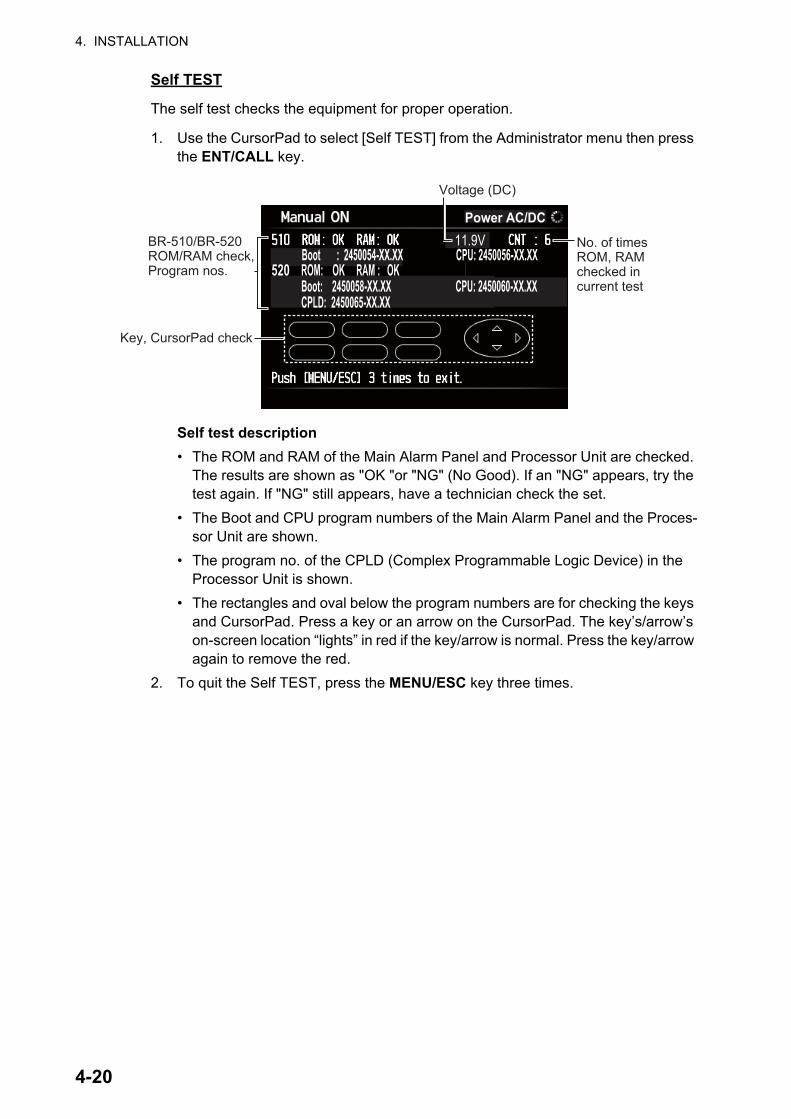
Self TEST
The self test checks the equipment for proper operation.
1. Use the CursorPad to select [Self TEST] from the Administrator menu then press the ENT/CALL key.
Self test description• The ROM and RAM of the Main Alarm Panel and Processor Unit are checked.
The results are shown as "OK "or "NG" (No Good). If an "NG" appears, try the test again. If "NG" still appears, have a technician check the set.
• The Boot and CPU program numbers of the Main Alarm Panel and the Proces-sor Unit are shown.
• The program no. of the CPLD (Complex Programmable Logic Device) in the Processor Unit is shown.
• The rectangles and oval below the program numbers are for checking the keys and CursorPad. Press a key or an arrow on the CursorPad. The key’s/arrow’s on-screen location “lights” in red if the key/arrow is normal. Press the key/arrow again to remove the red.
2. To quit the Self TEST, press the MENU/ESC key three times.
No. of timesROM, RAM checked in current test
Power AC/DC11.9V
Voltage (DC)
BR-510/BR-520ROM/RAM check,Program nos.
Key, CursorPad check
Boot : 2450054-XX.XX CPU: 2450056-XX.XX520 ROM: OK RAM : OK Boot: 2450058-XX.XX CPU: 2450060-XX.XX CPLD: 2450065-XX.XX
4-20
4. INSTALLATION
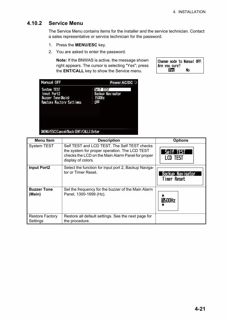
4.10.2 Service MenuThe Service Menu contains items for the installer and the service technician. Contact a sales representative or service technician for the password.
1. Press the MENU/ESC key.2. You are asked to enter the password.
Note: If the BNWAS is active, the message shown right appears. The cursor is selecting "Yes"; press the ENT/CALL key to show the Service menu.
Menu Item Description OptionsSystem TEST Self TEST and LCD TEST. The Self TEST checks
the system for proper operation. The LCD TEST checks the LCD on the Main Alarm Panel for proper display of colors.
Input Port2 Select the function for input port 2, Backup Naviga-tor or Timer Reset.
Buzzer Tone (Main)
Set the frequency for the buzzer of the Main Alarm Panel, 1300-1699 (Hz).
Restore Factory Settings
Restore all default settings. See the next page for the procedure.
Power AC/DC
4-21
4. INSTALLATION
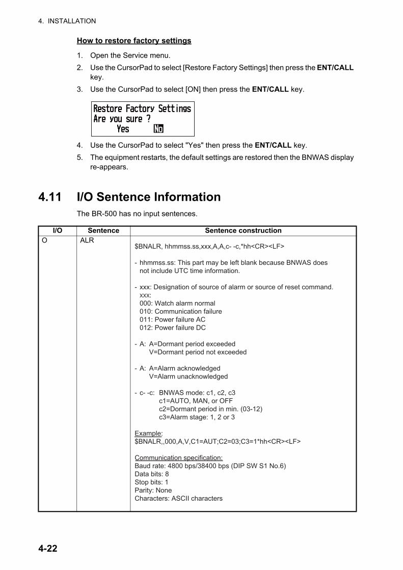
How to restore factory settings
1. Open the Service menu.2. Use the CursorPad to select [Restore Factory Settings] then press the ENT/CALL
key.3. Use the CursorPad to select [ON] then press the ENT/CALL key.
4. Use the CursorPad to select "Yes" then press the ENT/CALL key.5. The equipment restarts, the default settings are restored then the BNWAS display
re-appears.
4.11 I/O Sentence InformationThe BR-500 has no input sentences.
I/O Sentence Sentence constructionO ALR
$BNALR, hhmmss.ss,xxx,A,A,c- -c,*hh<CR><LF>
- hhmmss.ss: This part may be left blank because BNWAS does not include UTC time information.
- xxx: Designation of source of alarm or source of reset command. xxx: 000: Watch alarm normal 010: Communication failure 011: Power failure AC 012: Power failure DC
- A: A=Dormant period exceeded V=Dormant period not exceeded
- A: A=Alarm acknowledged V=Alarm unacknowledged
- c- -c: BNWAS mode: c1, c2, c3 c1=AUTO, MAN, or OFF c2=Dormant period in min. (03-12) c3=Alarm stage: 1, 2 or 3
Example:$BNALR,,000,A,V,C1=AUT;C2=03;C3=1*hh<CR><LF>
Communication specification:Baud rate: 4800 bps/38400 bps (DIP SW S1 No.6)Data bits: 8Stop bits: 1Parity: NoneCharacters: ASCII characters
4-22
APPENDIX 1 MENU TREE, ABBREVIA-TIONS, JIS CABLE GUIDE
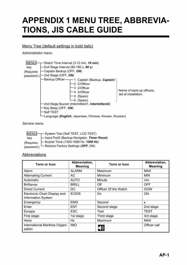
Menu Tree (default settings in bold italic)
Administrator menu
Service menu
Abbreviations
Term or Icon Abbreviation, Meaning Term or Icon Abbreviation,
MeaningAlarm ALARM Maximum MAXAlternating Current AC Minimum MINAutomatic AUTO Minute minBrilliance BRILL Off OFFDirect Current DC Officer Of the Watch OOWElectronic Chart Display and Information System
ECDIS On ON
Emergency EMG Second sEnter ENT Second stage 2nd stageEscape ESC Test TESTFirst stage 1st stage Third stage 3rd stageHertz Hz Maximum MAXInternational Maritime Organi-zation
IMO Officer call
MENUkey
(Requirespassword.)
Watch Time Interval (3-12 min, 10 min)2nd Stage Interval (90-180 s, 90 s)Captain Backup (OFF, ON)2nd Stage (OFF, ON)Backup Officer
2nd Stage Buzzer (Intermittent1, Intermittent2)Key Beep (OFF, ON)Self TESTLanguage (English, Japanese, Chinese, Korean, Russian)
1 Captain (Backup, Captain)2 C/Officer3 2/Officer4 3/Officer5 (Spare) 6 (Spare)
Name of back-up officers,set at installation.
System Test (Self TEST, LCD TEST)Input Port2 (Backup Navigator, Timer Reset)Buzzer Tone (1300-1699 Hz, 1500 Hz)Restore Factory Settings (OFF, ON)
MENUkey
(Requirespassword.)
AP-1
APPENDIX 1 MENU TREE, ABBREVIATIONS, JIS CABLE GUIDE
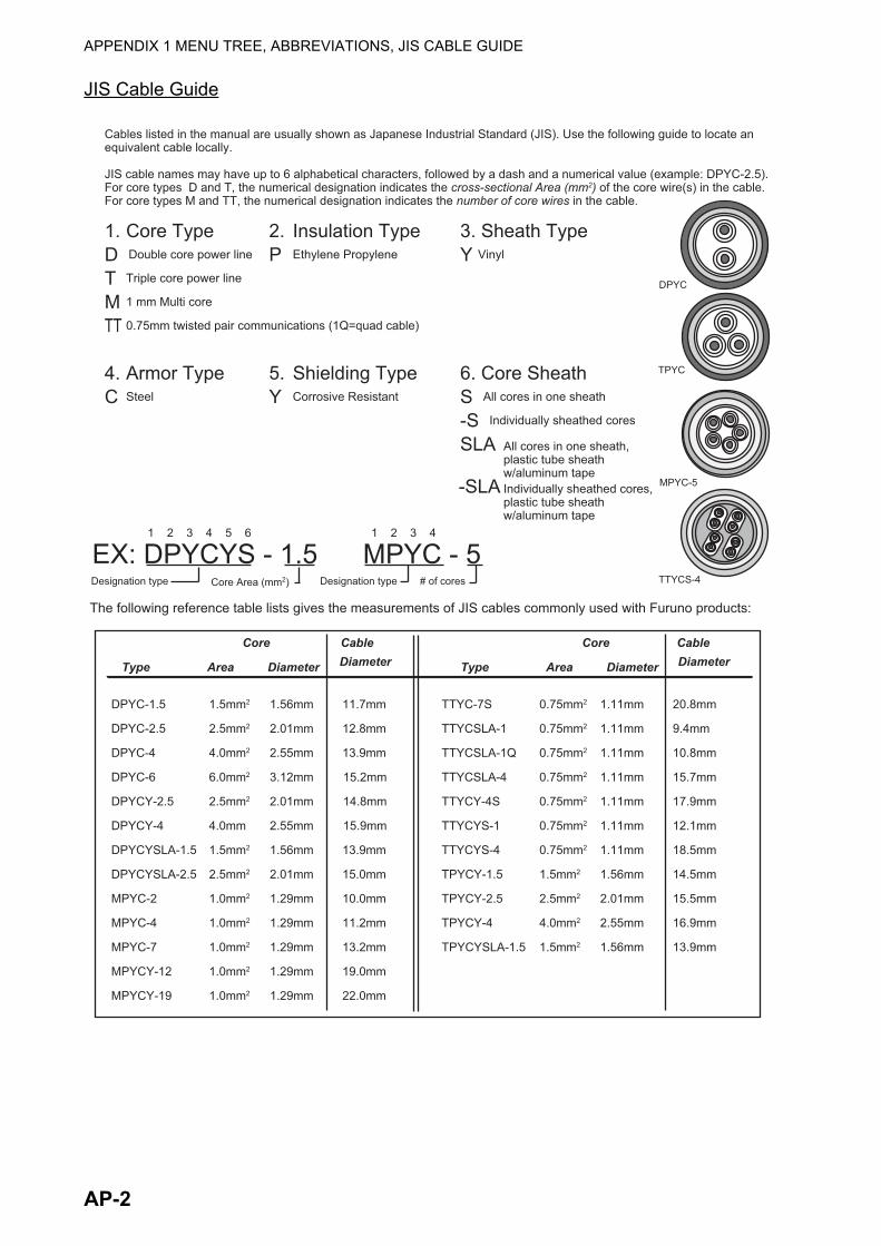
JIS Cable Guide
Core Cable Core Cable
Type Area Diameter Type Area Diameter
TTYCS-4
MPYC-5
TPYC
The following reference table lists gives the measurements of JIS cables commonly used with Furuno products:
Cables listed in the manual are usually shown as Japanese Industrial Standard (JIS). Use the following guide to locate an equivalent cable locally.
JIS cable names may have up to 6 alphabetical characters, followed by a dash and a numerical value (example: DPYC-2.5). For core types D and T, the numerical designation indicates the cross-sectional Area (mm2) of the core wire(s) in the cable. For core types M and TT, the numerical designation indicates the number of core wires in the cable.
1. Core Type 2. Insulation Type 3. Sheath TypeD Double core power line P Ethylene Propylene Y Vinyl T Triple core power line
M 1 mm Multi core
TT 0.75mm twisted pair communications (1Q=quad cable)
4. Armor Type 5. Shielding Type 6. Core SheathC Steel Y Corrosive Resistant S All cores in one sheath -S Individually sheathed cores
SLA
DPYC
Diameter Diameter
DPYC-1.5 1.5mm2 1.56mm 11.7mm
DPYC-2.5 2.5mm2 2.01mm 12.8mm
DPYC-4 4.0mm2 2.55mm 13.9mm
DPYC-6 6.0mm2 3.12mm 15.2mm
DPYCY-2.5 2.5mm2 2.01mm 14.8mm
DPYCY-4 4.0mm 2.55mm 15.9mm
DPYCYSLA-1.5 1.5mm2 1.56mm 13.9mm
DPYCYSLA-2.5 2.5mm2 2.01mm 15.0mm
MPYC-2 1.0mm2 1.29mm 10.0mm
MPYC-4 1.0mm2 1.29mm 11.2mm
MPYC-7 1.0mm2 1.29mm 13.2mm
MPYCY-12 1.0mm2 1.29mm 19.0mm
MPYCY-19 1.0mm2 1.29mm 22.0mm
TTYC-7S 0.75mm2 1.11mm 20.8mm
TTYCSLA-1 0.75mm2 1.11mm 9.4mm
TTYCSLA-1Q 0.75mm2 1.11mm 10.8mm
TTYCSLA-4 0.75mm2 1.11mm 15.7mm
TTYCY-4S 0.75mm2 1.11mm 17.9mm
TTYCYS-1 0.75mm2 1.11mm 12.1mm
TTYCYS-4 0.75mm2 1.11mm 18.5mm
TPYCY-1.5 1.5mm2 1.56mm 14.5mm
TPYCY-2.5 2.5mm2 2.01mm 15.5mm
TPYCY-4 4.0mm2 2.55mm 16.9mm
TPYCYSLA-1.5 1.5mm2 1.56mm 13.9mm
EX: DPYCYS - 1.5 MPYC - 5Designation type Core Area (mm2) Designation type # of cores
1 2 3 4 5 6 1 2 3 4
-SLA Individually sheathed cores, plastic tube sheathw/aluminum tape
All cores in one sheath, plastic tube sheathw/aluminum tape
AP-2
FURUNO BR-500
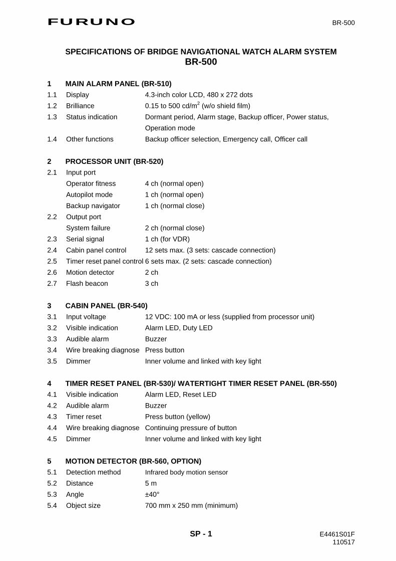
SPECIFICATIONS OF BRIDGE NAVIGATIONAL WATCH ALARM SYSTEM BR-500
1 MAIN ALARM PANEL (BR-510) 1.1 Display 4.3-inch color LCD, 480 x 272 dots 1.2 Brilliance 0.15 to 500 cd/m2 (w/o shield film) 1.3 Status indication Dormant period, Alarm stage, Backup officer, Power status,
Operation mode 1.4 Other functions Backup officer selection, Emergency call, Officer call 2 PROCESSOR UNIT (BR-520) 2.1 Input port
Operator fitness 4 ch (normal open) Autopilot mode 1 ch (normal open) Backup navigator 1 ch (normal close)
2.2 Output port System failure 2 ch (normal close)
2.3 Serial signal 1 ch (for VDR) 2.4 Cabin panel control 12 sets max. (3 sets: cascade connection) 2.5 Timer reset panel control 6 sets max. (2 sets: cascade connection) 2.6 Motion detector 2 ch 2.7 Flash beacon 3 ch 3 CABIN PANEL (BR-540) 3.1 Input voltage 12 VDC: 100 mA or less (supplied from processor unit) 3.2 Visible indication Alarm LED, Duty LED 3.3 Audible alarm Buzzer 3.4 Wire breaking diagnose Press button 3.5 Dimmer Inner volume and linked with key light 4 TIMER RESET PANEL (BR-530)/ WATERTIGHT TIMER RESET PANEL (BR-550) 4.1 Visible indication Alarm LED, Reset LED 4.2 Audible alarm Buzzer 4.3 Timer reset Press button (yellow) 4.4 Wire breaking diagnose Continuing pressure of button 4.5 Dimmer Inner volume and linked with key light 5 MOTION DETECTOR (BR-560, OPTION) 5.1 Detection method Infrared body motion sensor 5.2 Distance 5 m 5.3 Angle ±40° 5.4 Object size 700 mm x 250 mm (minimum)
SP - 1 E4461S01F 110517
FURUNO BR-500
SP - 2 E4461S01F 110517
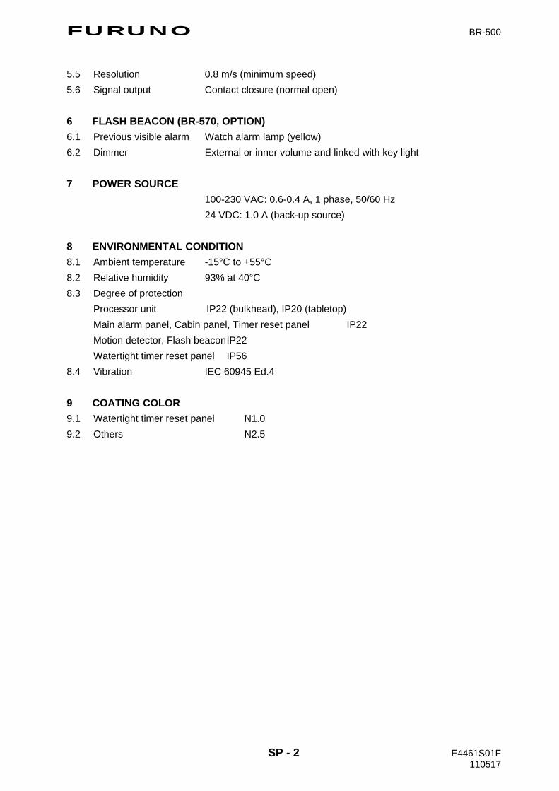
5.5 Resolution 0.8 m/s (minimum speed) 5.6 Signal output Contact closure (normal open) 6 FLASH BEACON (BR-570, OPTION) 6.1 Previous visible alarm Watch alarm lamp (yellow) 6.2 Dimmer External or inner volume and linked with key light 7 POWER SOURCE
100-230 VAC: 0.6-0.4 A, 1 phase, 50/60 Hz 24 VDC: 1.0 A (back-up source)
8 ENVIRONMENTAL CONDITION 8.1 Ambient temperature -15°C to +55°C 8.2 Relative humidity 93% at 40°C 8.3 Degree of protection
Processor unit IP22 (bulkhead), IP20 (tabletop) Main alarm panel, Cabin panel, Timer reset panel IP22 Motion detector, Flash beacon IP22 Watertight timer reset panel IP56
8.4 Vibration IEC 60945 Ed.4 9 COATING COLOR 9.1 Watertight timer reset panel N1.0 9.2 Others N2.5
A-2
A-1
A-4
A-3
A-6
A-5
A-8
A-7
A-10
A-9
D-1
D-2
D-4

D-8

D-11
1 2 4 5 63
B
A
D
C
NAME
名称
TITLE
kgMASS
DWG No.
SCALE
APPROVED
CHECKED
DRAWN
REF.No.
T.YAMASAKI
INTERCONNECTION DIAGRAM
相互結線図
BR-500
BRIDGE NAVIGATIONAL WATCH ALARM SYSTEM
21GND
3 4 5RST_RESET1
21GND
3 4 5 21GND
3 4 521GND
3 4 5 321 4
IV-2sq.*1
321 4
GND
5 6
12VAOUT
321 4
GND
5 6
12VAOUT
321 4
GND
5 6
12VAOUT
PUBLIC CABIN PANEL
PB_DUTY1
PB_ALM1
PB_BUZ1
PB_TEST1
PB_DUTY2
PB_ALM2
PB_BUZ2
PB_TEST2
PB_DUTY3
PB_ALM3
PB_BUZ3
PB_TEST3
同上
DITTO
同上
DITTO
321 4
GND
5 6
12VAOUT
321 4
GND
5 6
12VAOUT
OF_DUTY2
OF_ALM2
OF_BUZ2
OF_TEST2
OF_DUTY3
OF_ALM3
OF_BUZ3
OF_TEST3
321 4
GND
5 6
12VAOUT
321 4
GND
5 6
12VAOUT
OF_DUTY4
OF_ALM4
OF_BUZ4
OF_TEST4
OF_TEST5
OF_BUZ5
OF_ALM5
OF_DUTY5
321 4
GND
5 6
12VAOUT
OF_DUTY6
OF_ALM6
OF_BUZ6
OF_TEST6
同上
DITTO
同上
DITTO
同上
DITTO
同上
DITTO
IV-2sq.*1
1 2 3 4 5
NETWORK
P P
321 4 5
TB2
SHIELD
アオ
BLU
シロ
WHT
クロ
BLK
アカ
RED
SHIELD
GND
NET-H
NET-L
MAIN ALARM PANEL
メインアラームパネル
BR-510
5 6 7 8
GND
GND
GND
GND
TB16
*1
21GND
INPUT1
MPYC-2
AUTOPILOT
GND
GND
TB17
GND
GND
GND
INPUT6
INPUT7
INPUT8
TB211 2 3 4 5 6
GND
INPUT5
9 10
GND
*1
MPYC-2
BACK-UP
NAVIGATOR*5
321 4 5321
*1
TD-A
TD-B
SHIELD
MPYC-4,MAX.50m
4 5 6 7 8 9321SYS_FAIL_B1
SYS_FAIL_COM1
4SYS_FAIL_B2
SYS_FAIL_COM2
ALARM
SYSTEM
VDR
321 4 5
321GND
12VIN
BR-570FLASH BEACONフラッシュビーコン
*2
4 5DIM-P
DIM-N
MPYC-7*1
JB
同上
DITTO
同上
DITTO
*1MPYC-2
*1
TB18
TB19
GND
FLB1
GND
FLB2
GND
FLB3
TTYCS-1
TB20
TB14
TB15
TB9
TB10
TB11
TB12
TB13
TB8
TB6
TB5
TB4
TB3
船橋航海当直警報装置
DPYC-1.5
1φ,50/60Hz
*1
DPYC-2.5
24VDC
(BUCK-UP
BATTERY)
*1
OPERATOR FITNESS*4
*1
MPYC-7
12VAOUT
12VAOUT
12VAOUT
12VAOUT
12VAOUT
12VAOUT
12VAOUT
12VAOUT
12VBOUT
12VBOUT
RST_LED1
RST_LED2
RST_RESET2
12VBOUT
RST_LED3
RST_RESET3
12VBOUT
RST_LED4
RST_RESET4
321 4
GND
12VIN
SENSOR_OUT
GND
321 4
GND
12VIN
SENSOR_OUT
GND
MPYC-4,MAX.50m
*1
MPYC-4,MAX.50m
*1 *1
MPYC-2
*1
MPYC-2
*1
MPYC-2
*1
MPYC-2
*1
MPYC-2
*1
MPYC-2
VDR,
ETC.
*1
FLB
TIMER RESET PANEL (MAX. 6 SETS)TOTAL CABLE LENGTH: UP TO 150m
タイマーリセットパネル:最大6台。ケーブル長さ:全長150m以下。
*1
*1
321 4 5 6
GND
12V
DUTY
ALM
BUZ
CABIN PANEL
TEST
キャビンパネル
321 4 5 6
GND
12V
DUTY
ALM
BUZ
CABIN PANEL
TEST
321 4 5 6
GND
12V
DUTY
ALM
BUZ
CABIN PANEL
TEST
キャビンパネルキャビンパネル
321 4 5 6
GND
12V
DUTY
ALM
BUZ
CABIN PANEL
TEST
キャビンパネル
321 4 5 6
GND
12V
DUTY
ALM
BUZ
CABIN PANEL
TEST
キャビンパネル
BR-540 BR-540 BR-540 BR-540 BR-540
21
JB*1
3 4 5 6
*1
MPYC-7 TOTAL CABLE LENGTH: UP TO 80m
ケーブル長さ合計: 最大80m
CABIN PANEL: UP TO 12 SETS FOR OFFICER AND PUBLIC USE.TOTAL CABLE LENGTH: UP TO 300m
キャビンパネル:最大12台。ケーブル長さ:全長300m以下。
NET-S
NET-C
NET-H
NET-L
FG
RST_BUZ4
RST_BUZ3
RST_BUZ2
RST_BUZ1
6
(3kΩ)VOLUME
*2 *3 *2 *3
321 4 5 6
GND
12V
DUTY
ALM
BUZ
CABIN PANEL
TEST
キャビンパネル
BR-540
321 4
GND
5 6
12VAOUT
キャビンパネルの4芯ケーブル接続例
WITH 4-CORE CABLEEXAMPLE FOR CONNECTION CABIN PANEL
TB7-15
PB_DUTY
PB_ALM
PB_BUZ
PB_TEST
*1
MPYC-4
DUTY-LED AND TEST FUNCTIONS ARE DISABLEDUTY-LEDおよびTEST機能は使用不可
*2 *2 *3
H.MAKI
INPUT3
INPUT4
INPUT2
21TB1
3 4
AC
AC
(-)
(+)
PROCESSOR UNITBR-520
制御部
*4)モーション検出器に変更可能。 *4: CONNECTION CAN BE CHANGED TO MOTION DETECTOR.
*5)モーション検出器・オペレータフィットネスに変更可能。 *5: CONNECTION CAN BE CHANGED TO MOTION DETECTOR OR OPERATOR FITNESS.
*1)造船所手配。
注記
*2)オプション。
*1: SHIPYARD SUPPLY.
NOTE
*2: OPTION.
*3)キャビンパネルは最大3台まで接続可能。 *3: MAX.3 CABIN PANELS CAN BE INSTALLED.
100-230VAC
20/30/40/50m(*2)
*2 *2BR-560
モーション検出器MOTION DETECTOR
BR-560
モーション検出器MOTION DETECTOR
最大3台MAX. 3 SETS
最大2台 MAX. 2 SETS
321 4 5 6
GND
12VIN
NC
BUZ
RESET
BR-530
TIMER RESET PANELタイマーリセットパネル
321 4 5 6
GND
12VIN
NC
BUZ
RESET
BR-550
321 4 5 6
GND
12VIN
NC
BUZ
RESET
BR-530
321 4 5 6
GND
12VIN
NC
BUZ
RESET
BR-530
321 4 5 6
GND
12VIN
NC
BUZ
RESET
BR-550
321 4 5 6
GND
12VIN
NC
BUZ
RESET
BR-530 *2*2
TIMER RESET PANELWATERTIGHT防水型タイマーリセットパネル
TIMER RESET PANELWATERTIGHT
TIMER RESET PANELタイマーリセットパネル
防水型タイマーリセットパネル
21
JB*1
3 4 5 21
JB*1
3 4 5
LED
LED
LED
LED
LED
LED
TOTAL CABLE LENGTH: UP TO 40mケーブル長さ合計: 最大40m
TOTAL CABLE LENGTH: UP TO 40mケーブル長さ合計: 最大40m
*2*2*2*2
*1
MPYCY-7
*1
MPYCY-7
MPYC-7
MPYC-7*1
*1
MPYC(Y)-7
MPYC(Y)-7
24-012-6001-2
21
JB*1
3 4 5 6
TOTAL CABLE LENGTH: UP TO 80mケーブル長さ合計: 最大80m
OFFICER #1
FRU12-05AFFM-10M,10m
*1
MPYC-7
*1
MPYC-7
OFFICER CABIN PANEL
321 4 5 6
GND
12V
DUTY
ALM
BUZ
CABIN PANEL
TEST
キャビンパネル
BR-540 *2 *3*2
321 4
GND
5 6
12VAOUT
OF_DUTY1
OF_ALM1
OF_BUZ1
OF_TEST1
TB7
321 4 5 6
GND
12V
DUTY
ALM
BUZ
CABIN PANEL
TEST
キャビンパネル
BR-540
*1
MPYC-7
*2
CAPTAIN ROOM
3 45 6 7 8
19/Aug/2011
19/Aug/2011
C4461-C01- N
S-1
IN-1
INDEXNumerics2nd stage interval.................................... 4-18
AAbbreviations ..........................................AP-1Alarm sequence ........................................ 1-5
BBacklighting............................................... 1-3Backup officer ......................................... 4-19Backup officer selection ............................ 1-4BNWAS display......................................... 1-2Brilliance.................................................... 1-3Buzzer type ............................................. 4-19
CCabin paneloperation ................................................. 2-2troubleshooting........................................ 3-3
Captain backup ....................................... 4-18Control description .................................... 1-1
DDefault settings ....................................... 4-22
EEmergency call.......................................... 1-9EMG key ............................................1-1, 1-9ENT/CALL key .................................1-1, 1-10
FFlash Beacon ............................................ 2-4Fuse replacement ..................................... 3-2
HHelp area................................................... 1-8
KKey beep ................................................. 4-19
LLanguage ................................................ 4-19
MMaintenance.............................................. 3-1Menu tree ................................................AP-1MENU/ESC key......................................... 1-1MODE key.......................................... 1-1, 1-4Mode selection .......................................... 1-4Motion detector ......................................... 2-3
NNavigation officer call .............................. 1-10
OOperational event...................................... 1-9
PPower on/off .............................................. 1-1
RRESET key................................................ 1-1
SSEL key..............................................1-1, 1-4Software history ........................................... viSystem failure ........................................... 1-8
TTimer reset panel ...................................... 2-1Troubleshooting ........................................ 3-2
WWatch time interval.................................. 4-18Watertight timer reset panel ...................... 2-1