Embed Size (px)
Citation preview
_ARMTEC.COM
BRIDGE MATERIALS / BRIDGE GIRDERS /
BRIDGE GIRDERS TECHNICAL GUIDE
PRECAST CONCRETE GIRDERS AND BEAMS DESIGNED TO SUPPORT BRIDGE DECKSAND TRAFFIC LOADS
Proven strength
In-house engineering
Readily available
Various girder types
REGIONal SPECIFICaTIONS / aB / MB / SK
_BRIDGE GIRDERS
2
Proven strengthDurable, cost effective and easy to maintain
In-house engineering and installationable to meet unique aesthetic, schedule, span and load requirements
Readily availableManufactured year-round in controlled conditions
Various girder types NU, trapezoidal, single box, Saskatchewan SlC, Sl and SlW available
TYPICAL APPLICATIONS
•Road bridges•Pedestrian bridges•Rail bridges
NOTE
For girder details applicable to regions outside of armtec’s Prairie Region, refer to the appropriate Bridge Girders Technical Guide
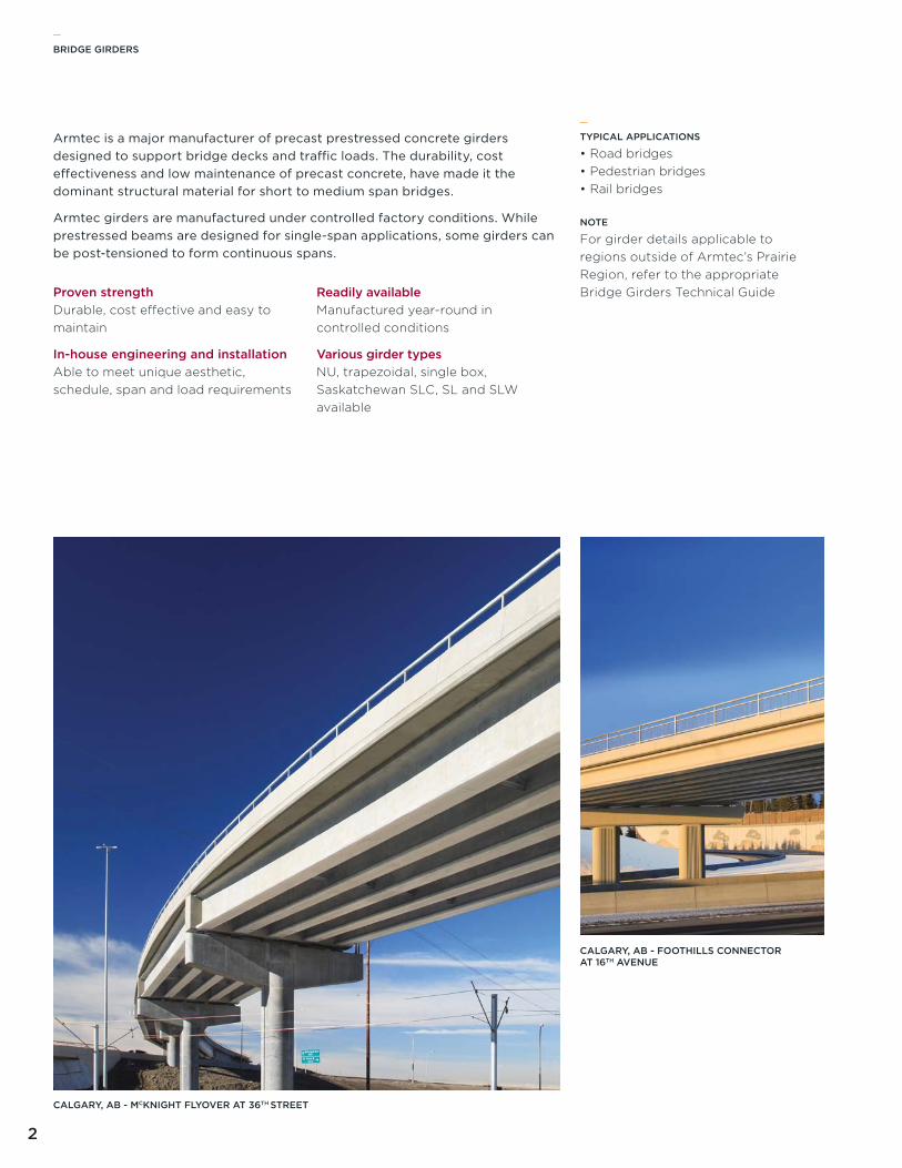
Armtec is a major manufacturer of precast prestressed concrete girders designed to support bridge decks and traffic loads. The durability, cost effectiveness and low maintenance of precast concrete, have made it the dominant structural material for short to medium span bridges.
Armtec girders are manufactured under controlled factory conditions. While prestressed beams are designed for single-span applications, some girders can be post-tensioned to form continuous spans.
_
CALGARY, AB - MCKNIGHT FLYOVER AT 36TH STREET
CALGARY, AB - FOOTHILLS CONNECTOR AT 16TH AVENUE
_BRIDGE GIRDERS
3
ConcreteThe high level of prestressing will normally require the use of high strength concrete. The span capability diagrams were developed using a 28-day concrete strength of ƒ'c=70MPa. The unit weight of concrete was assumed to be 2,450kg/m³. The concrete may contain silica fume with air entrainment of 5% to 8%.
The modulus of elasticity of concrete was calculated using the formula:
The minimum release strength assumed was 45MPa. Where there are two dashed lines in the charts, they represent limits for 45MPa and 50MPa release strength. any point on a chart above the 45MPa line indicates a situation where the release strength has to be higher than 45MPa due to handling stress limitations. This situation would require special mix designs which may increase the cost.
The concrete deck 28-day strength was assumed to be 45MPa.
TYPICAL APPLICATIONS
•Road bridges•Pedestrian bridges•Rail bridges
_
NU GIRDERS
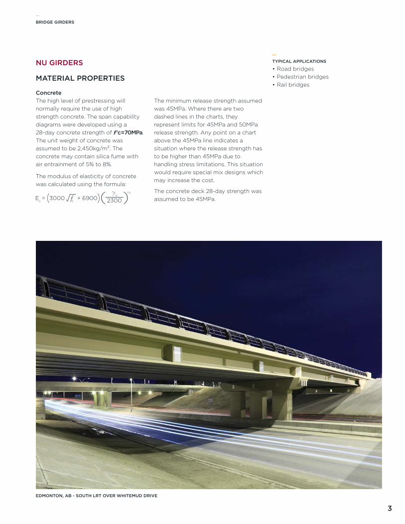
EDMONTON, AB - SOUTH LRT OVER WHITEMUD DRIVE
MATERIAL PROPERTIES
_BRIDGE GIRDERS
4
Lane Loada uniformly distributed load of 9kN/m, that is 3.0m wide as a lane load, superimposed with a Cl 800 truck, with each axle reduced to 80%
Truck Loada Cl 800 truck load, including a 25% dynamic load allowance
Dead LoadsDead loads considered to act on the untopped section are:
•Girder self weight•75mm thick haunch•225mm thick deck•Cross bracing (0.5kN/m per girder)
Superimposed Dead LoadsDead loads considered to act on the topped section are:
•90mm thick asphalt•Railing and curbs
(13kN/m total load per bridge)
Lanesa lane width of 3.3m, and the width of the bridge was calculated as:
•(# of lanes x lane Width) + 2 x 0.5m•Multi-lane reduction factor
(CaN/CSa-S6, Clause 3.8.4.2)
Prestress Lossesassumed average values of prestress losses:
•Initial losses = 8%•Final losses = 20%
Allowable Stresses
SERvICE
•Tension stresses at the bottom of the section at midspan are limited to
0.4 ƒ 'c•Compressive stress is not limited at
service, although the ratio c:dp is limited to 0.5
RElEaSE aND HaNDlING
•Tension stresses are limited to 0.5 ƒ 'ci (CaN/CSa-S6, Clause 8.8.4.6)
•Compressive stresses are limited to 0.6ƒ 'ci
SPAN CAPABILITY
DESIGN CRITERIA
Prestressing StrandThe prestressing strand is 15mm in diameter, uncoated, seven-wire, low relaxation strand, and meets the requirements of aSTM a416, with an area of 140mm².
The initial jacking force is 75% Apƒpu = 195kN
Girders with a Span to Depth Ratio >20 typically use up to an additional four 15mm strands in the top flange to control the lateral stability of the girder at handling and transportation. End stresses were not checked for all span conditions indicated in the charts. Stresses may be controlled by debonding and/or deflecting selected strands at the ends of the girders.
Post-TensioningNU Girders may be post-tensioned to form continuous beams. Reference should be made to CaN/CSa-S6.
For long span post-tensioned bridges, oiled strand (using approved corrosion inhibiting oil) may lead to decreased friction coefficients. Contact a local representative for more information about armtec’s experience constructing bridge beams with oiled post-tensioning strand.
The span capability charts were developed in accordance with the CaN/CSa-S6 Canadian Highway Bridge Design Code. Simple spans were assumed for all loads Calculations were done for interior girders.
_BRIDGE GIRDERS
5
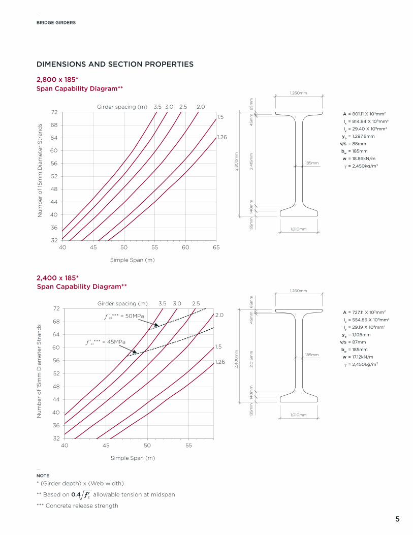
DIMENSIONS AND SECTION PROPERTIES
2,800 x 185*
2,400 x 185*
1,260mm
185mm
1,010mm135m
m14
0m
m2,
415
mm
45m
m6
5mm
2,8
00
mm
1,260mm
185mm
1,010mm135m
m14
0m
m2,
015
mm
45m
m6
5mm
2,4
00
mm
A
Ix
Iy
yb
V/S
bw
w
γ
= 801.11 X 103mm2
= 814.84 X 109mm4
= 29.40 X 109mm4
= 1,297.6mm
= 88mm
= 185mm
= 18.86kN/m
= 2,450kg/m3
A
Ix
Iy
yb
V/S
bw
w
γ
= 727.11 X 103mm²
= 554.86 X 109mm4
= 29.19 X 109mm4
= 1,106mm
= 87mm
= 185mm
= 17.12kN/m
= 2,450kg/m³
NOTE
* (Girder depth) x (Web width)
** Based on 0.4 ƒ 'c allowable tension at midspan
*** Concrete release strength
_
32
36
40
44
48
52
56
60
64
68
72
40 45 50 55 60 65
Nu
mb
er o
f 15
mm
Dia
met
er S
tran
ds
Simple Span (m)
Span Capability Diagram**
Girder spacing (m)
1.26
1.5
2.03.03.5 2.5
32
36
40
44
48
52
56
60
64
68
72
40 45 50 55
Simple Span (m)
Span Capability Diagram**
1.26
1.5
2.0
3.03.5
f 'ci*** = 45MPa
f 'ci*** = 50MPa
2.5Girder spacing (m)
Nu
mb
er o
f 15
mm
Dia
met
er S
tran
ds
_BRIDGE GIRDERS
6
20
24
28
32
36
40
44
48
52
56
60
25 30 35 40 45
Nu
mb
er o
f 15
mm
Dia
met
er S
tran
ds
Simple Span (m)
Span Capability Diagram**
Girder spacing (m)
1.26
1.52.02.53.5
f'ci*** = 45 MPa
f'ci*** = 50 MPa
3.0
28
32
36
40
44
48
52
56
60
64
68
30 35 40 45 50
Nu
mb
er o
f 15
mm
Dia
met
er S
tran
ds
Simple Span (m)
Span Capability Diagram**
Girder spacing (m)
1.26
1.5
2.0
2.53.5
f'ci*** = 45 MPa
f'ci*** = 50 MPa
3.0
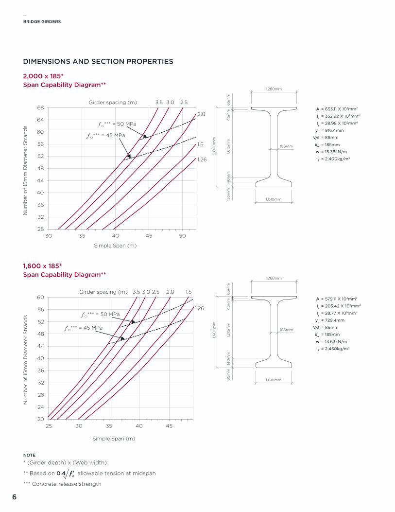
DIMENSIONS AND SECTION PROPERTIES
2,000 x 185*
1,600 x 185*
1,260mm
185mm
1,010mm135m
m14
0m
m1,6
15m
m4
5mm
65m
m
2,0
00
mm
1,260mm
185mm
1,010mm135m
m14
0m
m1,2
15m
m4
5mm
65m
m
1,60
0m
m
A
Ix
Iy
yb
V/S
bw
w
γ
A
Ix
Iy
yb
V/S
bw
w
γ
= 579.11 X 103mm2
= 203.42 X 109mm4
= 28.77 X 109mm4
= 729.4mm
= 86mm
= 185mm
= 13.63kN/m
= 2,450kg/m3
= 653.11 X 103mm2
= 352.92 X 109mm4
= 28.98 X 109mm4
= 916.4mm
= 86mm
= 185mm
= 15.38kN/m
= 2,400kg/m3
NOTE
* (Girder depth) x (Web width)
** Based on 0.4 ƒ 'c allowable tension at midspan
*** Concrete release strength
_BRIDGE GIRDERS
7
16
20
24
28
32
36
40
44
48
52
20 25 30 35 40
Nu
mb
er o
f 15
mm
Dia
met
er S
tran
ds
Simple Span (m)
Span Capability Diagram**
Girder spacing (m)
1.26
1.52.02.53.0
f'ci*** = 45 MPa
f'ci*** = 50 MPa
3.5
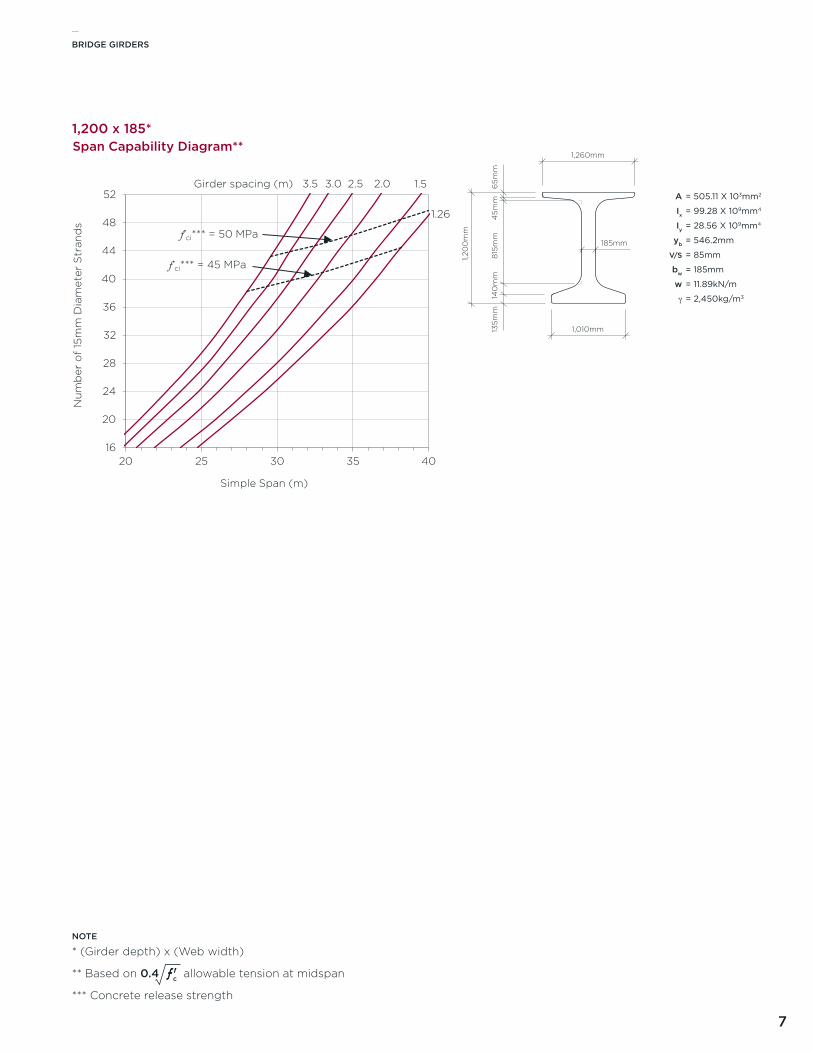
1,200 x 185*
1,260mm
185mm
1,010mm135m
m14
0m
m8
15m
m4
5mm
65m
m
1,20
0m
m
A
Ix
Iy
yb
V/S
bw
w
γ
= 505.11 X 103mm2
= 99.28 X 109mm4
= 28.56 X 109mm4
= 546.2mm
= 85mm
= 185mm
= 11.89kN/m
= 2,450kg/m3
NOTE
* (Girder depth) x (Web width)
** Based on 0.4 ƒ 'c allowable tension at midspan
*** Concrete release strength
_BRIDGE GIRDERS
8
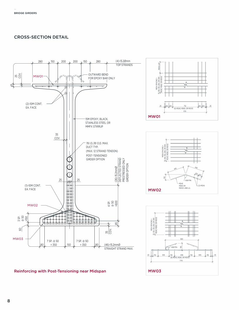
CROSS-SECTION DETAIL
Reinforcing with Post-Tensioning near Midspan
SCALE: SCALE 1:15
����
SCALE: SCALE 1:15
����SCALE: SCALE 1:15
MW03
MW02
MW01
����
MES
H SP
ACIN
G =
75, 1
00, 1
50, 2
00, O
R 30
0M
D45,
MD6
5, O
R M
D103
1710
43 152 305 152 406(8)-MD45, MD65, OR MD103
152 305 152 43
195
920
80Ø PIN
603
SP.
@ 5
0=1
50
807 SP. @ 50
= 350 150 807 SP. @ 50
= 350
25 COV
35COV
15M EPOXY, BLACK, STAINLESS STEEL ORMMFX STIRRUP
(2)-10M CONT.EA. FACE
4 SP
.@
50
=600
45
280 150 200 200 150 280 (4)-15.2Ømm TOP STRANDS
(46)-15.2mmØ STRAIGHT STRAND MAX.
(26)
-15.2
mm
Ø
DEFL
ECTE
D ST
RAND
35 COV.
OUTWARD BENDFOR EPOXY BAR ONLY
(1)-10M CONT.EA. FACE
85
2525
78 I.D./81 O.D. MAX.DUCT TYP.(MAX. 12 STRAND TENDON)
MES
H LA
P
1170
25 102 712(6)-MD45, MD65, OR MD103
102 25102102
MES
H SP
ACIN
G =
75, 1
00, 1
50, 2
00, O
R 30
0M
D45,
MD6
5, O
R M
D103
150
102102
445445
(2)-MD45
60Ø PIN
MD45MD65 ORMD103 x 890 LG.
MES
H SP
ACIN
G =
75, 1
00, 1
50, 2
00, O
R 30
0M
D45,
MD6
5, O
R M
D103
POST-TENSIONEDGIRDER OPTION
PRES
TRES
SED
ONL
YGI
RDER
OPT
ION
105 3 SP. @ 200 = 600 105
1010 (+0,-2)
150
PL. 22 x650 x1010C/W (20)-19Ø x125 LG. H.A.S. (10)-19Ø x75 LG. H.A.S.
20 x20 CHAMFERTYP.
220
20
100 100
650
100
4 SP
. @ 10
0 =
400
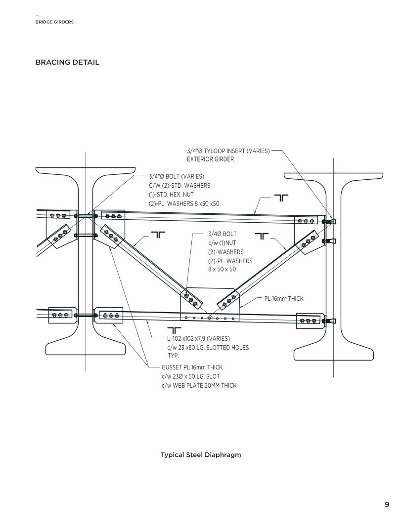
GUSSET PL 16mm THICKc/w 23Ø x 50 LG. SLOTc/w WEB PLATE 20MM THICK
3/4"Ø BOLT (VARIES)C/W (2)-STD. WASHERS(1)-STD. HEX. NUT(2)-PL. WASHERS 8 x50 x50
L. 102 x102 x7.9 (VARIES)c/w 23 x50 LG. SLOTTED HOLESTYP.
PL 16mm THICK
3/4"Ø TYLOOP INSERT (VARIES)EXTERIOR GIRDER
3/4Ø BOLT c/w (1)NUT(2)-WASHERS(2)-PL. WASHERS8 x 50 x 50
MW02
MW03
MW01
SCALE: SCALE 1:15
����
SCALE: SCALE 1:15
����SCALE: SCALE 1:15
MW03
MW02
MW01
����
MES
H SP
ACIN
G =
75, 1
00, 1
50, 2
00, O
R 30
0M
D45,
MD6
5, O
R M
D103
1710
43 152 305 152 406(8)-MD45, MD65, OR MD103
152 305 152 43
195
920
80Ø PIN
603
SP.
@ 5
0=1
50
807 SP. @ 50
= 350 150 807 SP. @ 50
= 350
25 COV
35COV
15M EPOXY, BLACK, STAINLESS STEEL ORMMFX STIRRUP
(2)-10M CONT.EA. FACE
4 SP
.@
50
=600
45280 150 200 200 150 280 (4)-15.2Ømm
TOP STRANDS
(46)-15.2mmØ STRAIGHT STRAND MAX.
(26)
-15.2
mm
Ø
DEFL
ECTE
D ST
RAND
35 COV.
OUTWARD BENDFOR EPOXY BAR ONLY
(1)-10M CONT.EA. FACE
85
2525
78 I.D./81 O.D. MAX.DUCT TYP.(MAX. 12 STRAND TENDON)
MES
H LA
P
1170
25 102 712(6)-MD45, MD65, OR MD103
102 25102102
MES
H SP
ACIN
G =
75, 1
00, 1
50, 2
00, O
R 30
0M
D45,
MD6
5, O
R M
D103
150
102102
445445
(2)-MD45
60Ø PIN
MD45MD65 ORMD103 x 890 LG.
MES
H SP
ACIN
G =
75, 1
00, 1
50, 2
00, O
R 30
0M
D45,
MD6
5, O
R M
D103
POST-TENSIONEDGIRDER OPTION
PRES
TRES
SED
ONL
YGI
RDER
OPT
ION
105 3 SP. @ 200 = 600 105
1010 (+0,-2)
150
PL. 22 x650 x1010C/W (20)-19Ø x125 LG. H.A.S. (10)-19Ø x75 LG. H.A.S.
20 x20 CHAMFERTYP.
220
20
100 100
650
100
4 SP
. @ 10
0 =
400
GUSSET PL 16mm THICKc/w 23Ø x 50 LG. SLOTc/w WEB PLATE 20MM THICK
3/4"Ø BOLT (VARIES)C/W (2)-STD. WASHERS(1)-STD. HEX. NUT(2)-PL. WASHERS 8 x50 x50
L. 102 x102 x7.9 (VARIES)c/w 23 x50 LG. SLOTTED HOLESTYP.
PL 16mm THICK
3/4"Ø TYLOOP INSERT (VARIES)EXTERIOR GIRDER
3/4Ø BOLT c/w (1)NUT(2)-WASHERS(2)-PL. WASHERS8 x 50 x 50
MW01
SCALE: SCALE 1:15
����
SCALE: SCALE 1:15
����SCALE: SCALE 1:15
MW03
MW02
MW01
����
MES
H SP
ACIN
G =
75, 1
00, 1
50, 2
00, O
R 30
0M
D45,
MD6
5, O
R M
D103
1710
43 152 305 152 406(8)-MD45, MD65, OR MD103
152 305 152 43
195
920
80Ø PIN
603
SP.
@ 5
0=1
50
807 SP. @ 50
= 350 150 807 SP. @ 50
= 350
25 COV
35COV
15M EPOXY, BLACK, STAINLESS STEEL ORMMFX STIRRUP
(2)-10M CONT.EA. FACE
4 SP
.@
50
=600
45
280 150 200 200 150 280 (4)-15.2Ømm TOP STRANDS
(46)-15.2mmØ STRAIGHT STRAND MAX.
(26)
-15.2
mm
Ø
DEFL
ECTE
D ST
RAND
35 COV.
OUTWARD BENDFOR EPOXY BAR ONLY
(1)-10M CONT.EA. FACE
85
2525
78 I.D./81 O.D. MAX.DUCT TYP.(MAX. 12 STRAND TENDON)
MES
H LA
P
1170
25 102 712(6)-MD45, MD65, OR MD103
102 25102102
MES
H SP
ACIN
G =
75, 1
00, 1
50, 2
00, O
R 30
0M
D45,
MD6
5, O
R M
D103
150
102102
445445
(2)-MD45
60Ø PIN
MD45MD65 ORMD103 x 890 LG.
MES
H SP
ACIN
G =
75, 1
00, 1
50, 2
00, O
R 30
0M
D45,
MD6
5, O
R M
D103
POST-TENSIONEDGIRDER OPTION
PRES
TRES
SED
ONL
YGI
RDER
OPT
ION
105 3 SP. @ 200 = 600 105
1010 (+0,-2)
150
PL. 22 x650 x1010C/W (20)-19Ø x125 LG. H.A.S. (10)-19Ø x75 LG. H.A.S.
20 x20 CHAMFERTYP.
220
20
100 100
650
100
4 SP
. @ 10
0 =
400
GUSSET PL 16mm THICKc/w 23Ø x 50 LG. SLOTc/w WEB PLATE 20MM THICK
3/4"Ø BOLT (VARIES)C/W (2)-STD. WASHERS(1)-STD. HEX. NUT(2)-PL. WASHERS 8 x50 x50
L. 102 x102 x7.9 (VARIES)c/w 23 x50 LG. SLOTTED HOLESTYP.
PL 16mm THICK
3/4"Ø TYLOOP INSERT (VARIES)EXTERIOR GIRDER
3/4Ø BOLT c/w (1)NUT(2)-WASHERS(2)-PL. WASHERS8 x 50 x 50
MW02
SCALE: SCALE 1:15
����
SCALE: SCALE 1:15
����SCALE: SCALE 1:15
MW03
MW02
MW01
����
MES
H SP
ACIN
G =
75, 1
00, 1
50, 2
00, O
R 30
0M
D45,
MD6
5, O
R M
D103
1710
43 152 305 152 406(8)-MD45, MD65, OR MD103
152 305 152 43
195
920
80Ø PIN
603
SP.
@ 5
0=1
50
807 SP. @ 50
= 350 150 807 SP. @ 50
= 350
25 COV
35COV
15M EPOXY, BLACK, STAINLESS STEEL ORMMFX STIRRUP
(2)-10M CONT.EA. FACE
4 SP
.@
50
=600
45
280 150 200 200 150 280 (4)-15.2Ømm TOP STRANDS
(46)-15.2mmØ STRAIGHT STRAND MAX.
(26)
-15.2
mm
Ø
DEFL
ECTE
D ST
RAND
35 COV.
OUTWARD BENDFOR EPOXY BAR ONLY
(1)-10M CONT.EA. FACE
85
2525
78 I.D./81 O.D. MAX.DUCT TYP.(MAX. 12 STRAND TENDON)
MES
H LA
P
1170
25 102 712(6)-MD45, MD65, OR MD103
102 25102102
MES
H SP
ACIN
G =
75, 1
00, 1
50, 2
00, O
R 30
0M
D45,
MD6
5, O
R M
D103
150
102102
445445
(2)-MD45
60Ø PIN
MD45MD65 ORMD103 x 890 LG.
MES
H SP
ACIN
G =
75, 1
00, 1
50, 2
00, O
R 30
0M
D45,
MD6
5, O
R M
D103
POST-TENSIONEDGIRDER OPTION
PRES
TRES
SED
ONL
YGI
RDER
OPT
ION
105 3 SP. @ 200 = 600 105
1010 (+0,-2)
150
PL. 22 x650 x1010C/W (20)-19Ø x125 LG. H.A.S. (10)-19Ø x75 LG. H.A.S.
20 x20 CHAMFERTYP.
220
20
100 100
650
100
4 SP
. @ 10
0 =
400
GUSSET PL 16mm THICKc/w 23Ø x 50 LG. SLOTc/w WEB PLATE 20MM THICK
3/4"Ø BOLT (VARIES)C/W (2)-STD. WASHERS(1)-STD. HEX. NUT(2)-PL. WASHERS 8 x50 x50
L. 102 x102 x7.9 (VARIES)c/w 23 x50 LG. SLOTTED HOLESTYP.
PL 16mm THICK
3/4"Ø TYLOOP INSERT (VARIES)EXTERIOR GIRDER
3/4Ø BOLT c/w (1)NUT(2)-WASHERS(2)-PL. WASHERS8 x 50 x 50
MW03
_BRIDGE GIRDERS
9
BRACING DETAIL
Typical Steel Diaphragm
SCALE: SCALE 1:15
����
SCALE: SCALE 1:15
����SCALE: SCALE 1:15
MW03
MW02
MW01
����
MES
H SP
ACIN
G =
75, 1
00, 1
50, 2
00, O
R 30
0M
D45,
MD6
5, O
R M
D103
1710
43 152 305 152 406(8)-MD45, MD65, OR MD103
152 305 152 43
195
920
80Ø PIN
603
SP.
@ 5
0=1
50
807 SP. @ 50
= 350 150 807 SP. @ 50
= 350
25 COV
35COV
15M EPOXY, BLACK, STAINLESS STEEL ORMMFX STIRRUP
(2)-10M CONT.EA. FACE
4 SP
.@
50
=600
45
280 150 200 200 150 280 (4)-15.2Ømm TOP STRANDS
(46)-15.2mmØ STRAIGHT STRAND MAX.
(26)
-15.2
mm
Ø
DEFL
ECTE
D ST
RAND
35 COV.
OUTWARD BENDFOR EPOXY BAR ONLY
(1)-10M CONT.EA. FACE
85
2525
78 I.D./81 O.D. MAX.DUCT TYP.(MAX. 12 STRAND TENDON)
MES
H LA
P
1170
25 102 712(6)-MD45, MD65, OR MD103
102 25102102
MES
H SP
ACIN
G =
75, 1
00, 1
50, 2
00, O
R 30
0M
D45,
MD6
5, O
R M
D103
150
102102
445445
(2)-MD45
60Ø PIN
MD45MD65 ORMD103 x 890 LG.
MES
H SP
ACIN
G =
75, 1
00, 1
50, 2
00, O
R 30
0M
D45,
MD6
5, O
R M
D103
POST-TENSIONEDGIRDER OPTION
PRES
TRES
SED
ONL
YGI
RDER
OPT
ION
105 3 SP. @ 200 = 600 105
1010 (+0,-2)
150
PL. 22 x650 x1010C/W (20)-19Ø x125 LG. H.A.S. (10)-19Ø x75 LG. H.A.S.
20 x20 CHAMFERTYP.
220
20
100 100
650
100
4 SP
. @ 10
0 =
400
GUSSET PL 16mm THICKc/w 23Ø x 50 LG. SLOTc/w WEB PLATE 20MM THICK
3/4"Ø BOLT (VARIES)C/W (2)-STD. WASHERS(1)-STD. HEX. NUT(2)-PL. WASHERS 8 x50 x50
L. 102 x102 x7.9 (VARIES)c/w 23 x50 LG. SLOTTED HOLESTYP.
PL 16mm THICK
3/4"Ø TYLOOP INSERT (VARIES)EXTERIOR GIRDER
3/4Ø BOLT c/w (1)NUT(2)-WASHERS(2)-PL. WASHERS8 x 50 x 50
_BRIDGE GIRDERS
10
1010 (+0,-2)
105 105100 1003 SP. @ 200 = 600
60
5
100
150
4 S
P. @
10
0 =
40
0
202
20
20 x 20 CHAMFERTYP.
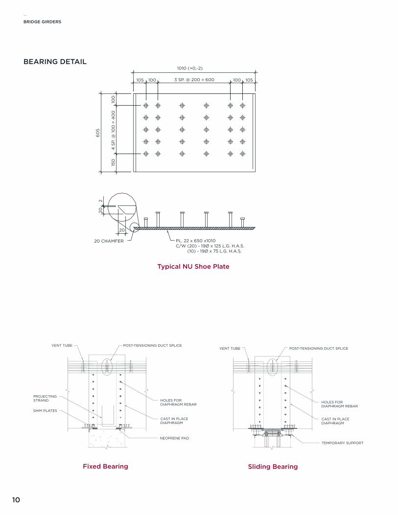
PL. 22 x 650 x1010C/W (20) - 19Ø x 125 L.G. H.A.S. (10) - 19Ø x 75 L.G. H.A.S.
POST-TENSIONING DUCT SPLICE
HOLES FOR DIAPHRAGM REBAR
CAST IN PLACEDIAPHRAGM
TEMPORARY SUPPORT
VENT TUBE
BEARING DETAIL 2SLIDING BEARING @ PIER
BEARING DETAIL
Typical NU Shoe Plate
BEARING DETAIL 1FIXED BEARING @ PIER
HOLES FORDIAPHRAGM REBAR
CAST IN PLACEDIAPHRAGM
POST-TENSIONING DUCT SPLICE
SHIM PLATES
PROJECTING STRAND
NEOPRENE PAD
VENT TUBE
Sliding BearingFixed Bearing
_BRIDGE GIRDERS
11
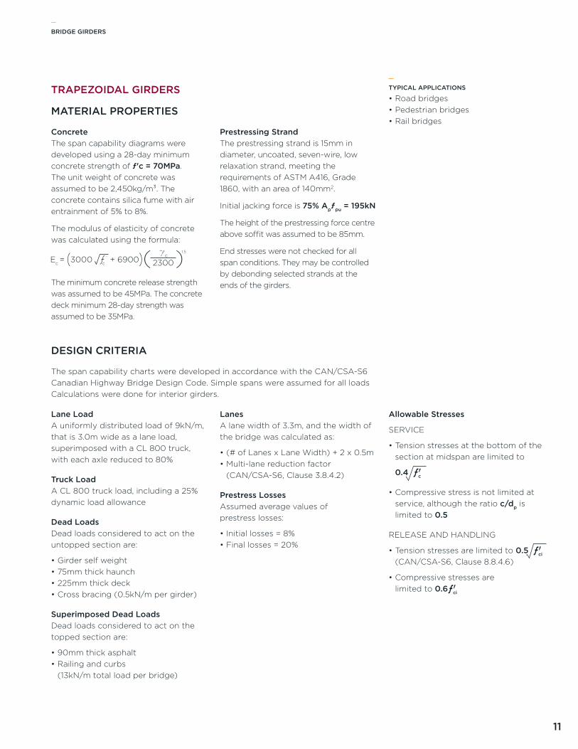
ConcreteThe span capability diagrams were developed using a 28-day minimum concrete strength of ƒ'c = 70MPa. The unit weight of concrete was assumed to be 2,450kg/m³. The concrete contains silica fume with air entrainment of 5% to 8%.
The modulus of elasticity of concrete was calculated using the formula:
The minimum concrete release strength was assumed to be 45MPa. The concrete deck minimum 28-day strength was assumed to be 35MPa.
Prestressing StrandThe prestressing strand is 15mm in diameter, uncoated, seven-wire, low relaxation strand, meeting the requirements of aSTM a416, Grade 1860, with an area of 140mm2.
Initial jacking force is 75% Apƒpu = 195kN
The height of the prestressing force centre above soffit was assumed to be 85mm.
End stresses were not checked for all span conditions. They may be controlled by debonding selected strands at the ends of the girders.
TYPICAL APPLICATIONS
•Road bridges•Pedestrian bridges•Rail bridges
_
TRAPEZOIDAL GIRDERS
MATERIAL PROPERTIES
Lane Loada uniformly distributed load of 9kN/m, that is 3.0m wide as a lane load, superimposed with a Cl 800 truck, with each axle reduced to 80%
Truck Loada Cl 800 truck load, including a 25% dynamic load allowance
Dead LoadsDead loads considered to act on the untopped section are:
•Girder self weight•75mm thick haunch•225mm thick deck•Cross bracing (0.5kN/m per girder)
Superimposed Dead LoadsDead loads considered to act on the topped section are:
•90mm thick asphalt•Railing and curbs
(13kN/m total load per bridge)
Lanesa lane width of 3.3m, and the width of the bridge was calculated as:
•(# of lanes x lane Width) + 2 x 0.5m•Multi-lane reduction factor
(CaN/CSa-S6, Clause 3.8.4.2)
Prestress Lossesassumed average values of prestress losses:
•Initial losses = 8%•Final losses = 20%
Allowable Stresses
SERvICE
•Tension stresses at the bottom of the section at midspan are limited to
0.4 ƒ 'c•Compressive stress is not limited at
service, although the ratio c/dp is limited to 0.5
RElEaSE aND HaNDlING
•Tension stresses are limited to 0.5 ƒ 'ci (CaN/CSa-S6, Clause 8.8.4.6)
•Compressive stresses are limited to 0.6ƒ 'ci
DESIGN CRITERIA
The span capability charts were developed in accordance with the CaN/CSa-S6 Canadian Highway Bridge Design Code. Simple spans were assumed for all loads Calculations were done for interior girders.
_BRIDGE GIRDERS
12
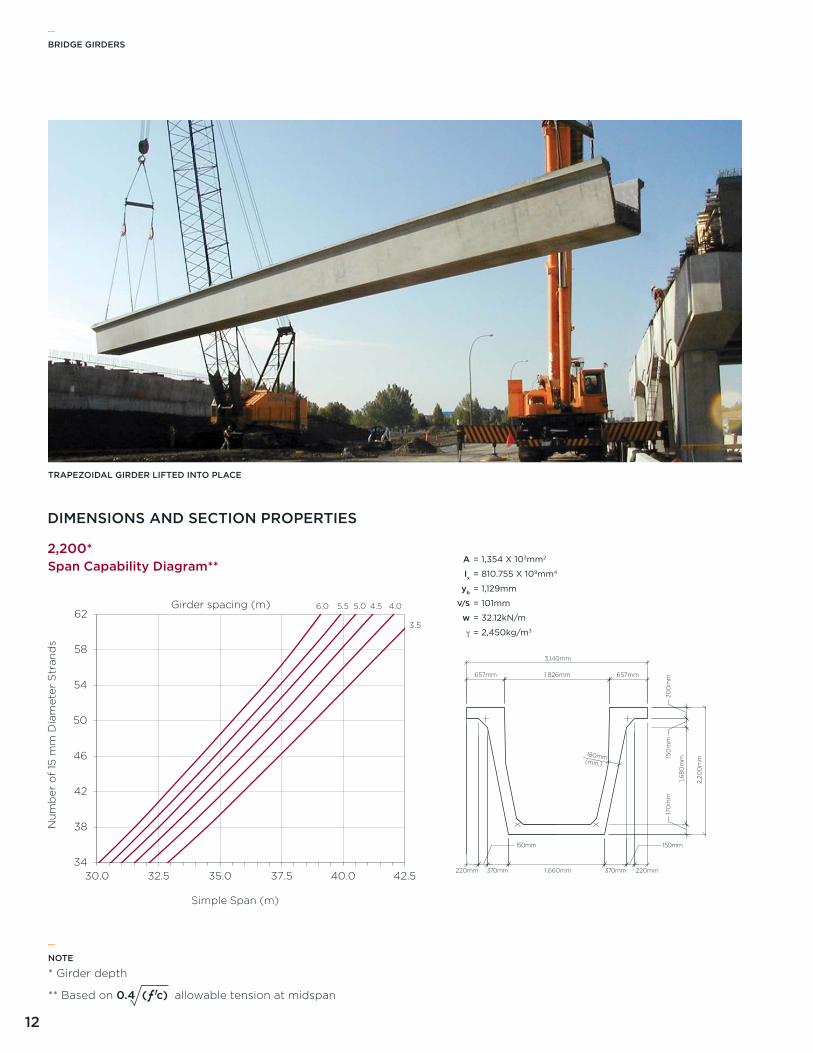
TRAPEZOIDAL GIRDER LIFTED INTO PLACE
34
38
42
46
50
54
58
62
30.0 32.5 35.0 37.5 40.0 42.5
Nu
mb
er o
f 15
mm
Dia
met
er S
tran
ds
Simple Span (m)
Span Capability Diagram**
Girder spacing (m)
3.5
4.04.55.05.56.0
DIMENSIONS AND SECTION PROPERTIES
2,200*
657mm 657mm1,826mm20
0m
m15
0m
m17
0m
m
2,20
0m
m
220mm1,660mm370mm
150mm
370mm220mm
180mm(min.)
3,140mm
1,680
mm
150mm
A
Ix
yb
V/S
w
γ
= 1,354 X 103mm2
= 810.755 X 109mm4
= 1,129mm
= 101mm
= 32.12kN/m
= 2,450kg/m3
NOTE
* Girder depth
** Based on 0.4 (ƒ ' c) allowable tension at midspan
_

_BRIDGE GIRDERS
13
A
Ix
yb
V/S
w
γ
34
38
42
46
50
54
58
62
30.0 32.5 35.0 37.5 40.0 42.5
Nu
mb
er o
f 15
mm
Dia
met
er S
tran
ds
Simple Span (m)
Span Capability Diagram**
Girder spacing (m) 3.54.04.55.05.56.0
34
38
42
46
50
54
58
62
30.0 32.5 35.0 37.5 40.0 42.5
Nu
mb
er o
f 15
mm
Dia
met
er S
tran
ds
Simple Span (m)
Span Capability Diagram**
Girder spacing (m) 3.54.04.55.05.56.0
DIMENSIONS AND SECTION PROPERTIES
2,000*
2,050*A
Ix
yb
V/S
w
γ
= 1,265 X 103mm2
= 668.538 X 109mm4
= 1,039mm
= 98mm
= 30.4kN/m
= 2,450kg/m3
= 1,198 X 103mm2
= 600.22 X 109mm4
= 984mm
= 94mm
= 29.54kN/m
= 2,450kg/m3
NOTE
* Girder depth
** Based on 0.4 (ƒ ' c) allowable tension at midspan
662mm 662mm1,816mm
200
mm
150
mm
170
mm
2,0
50m
m
250mm1,660mm340mm
150mm
340mm250mm
180mm(min.)
3,140mm
1,530
mm
150mm
1,350mm
662mm 662mm1,816mm
200
mm
150
mm
170
mm
2,0
00
mm
260mm1,660mm330mm
150mm
330mm260mm
180mm(min.)
3,140mm
1,480
mm
150mm
1,350mm
_BRIDGE GIRDERS
14
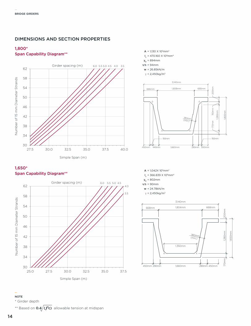
A
Ix
yb
V/S
w
γ
= 1,130 X 103mm2
= 470.160 X 109mm4
= 894mm
= 94mm
= 26.85kN/m
= 2,450kg/m3
= 1,042X 103mm2
= 366.839 X 109mm4
= 802mm
= 90mm
= 24.78kN/m
= 2,450kg/m3
A
Ix
yb
V/S
w
γ
30
34
38
42
46
50
54
58
62
27.5 30.0 32.5 35.0 37.5 40.0
Nu
mb
er o
f 15
mm
Dia
met
er S
tran
ds
Simple Span (m)
Span Capability Diagram**
Girder spacing (m) 3.54.04.55.05.56.0
1,800*
NOTE
* Girder depth
** Based on 0.4 (ƒ ' c) allowable tension at midspan
_
30
34
38
42
46
50
54
58
62
25.0 27.5 30.0 32.5 35.0 37.5
Nu
mb
er o
f 15
mm
Dia
met
er S
tran
ds
Simple Span (m)
Span Capability Diagram**
Girder spacing (m)
3.5
4.04.55.05.56.0
1,650*
666mm 666mm1,808mm
200
mm
150
mm
170
mm
1,80
0m
m
300mm1,660mm440mm
150mm
290mm450mm
180mm(min.)
3,140mm
1,280
mm
150mm
668mm 668mm1,804mm
200
mm
170
mm
1,650
mm
450mm1,660mm290mm 290mm450mm
180mm(min.)
3,140mm
1,350mm
1,280
mm
DIMENSIONS AND SECTION PROPERTIES
_BRIDGE GIRDERS
15
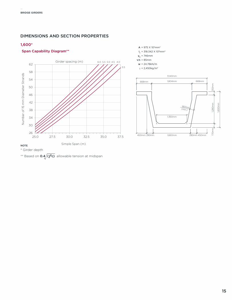
A
Ix
yb
V/S
w
γ
= 975 X 103mm2
= 318.342 X 109mm4
= 746mm
= 85mm
= 24.78kN/m
= 2,450kg/m3
26
30
34
38
42
46
50
54
58
62
25.0 27.5 30.0 32.5 35.0 37.5
Nu
mb
er o
f 15
mm
Dia
met
er S
tran
ds
Simple Span (m)
Span Capability Diagram**
Girder spacing (m)
3.5
4.04.55.05.56.0
DIMENSIONS AND SECTION PROPERTIES
NOTE
* Girder depth
** Based on 0.4 (ƒ ' c) allowable tension at midspan
1,600*
668mm 668mm1,804mm
150
mm
170
mm
1,60
0m
m
450mm1,660mm290mm 290mm450mm
180mm(min.)
3,140mm
1,350mm
1,280
mm
_BRIDGE GIRDERS
16
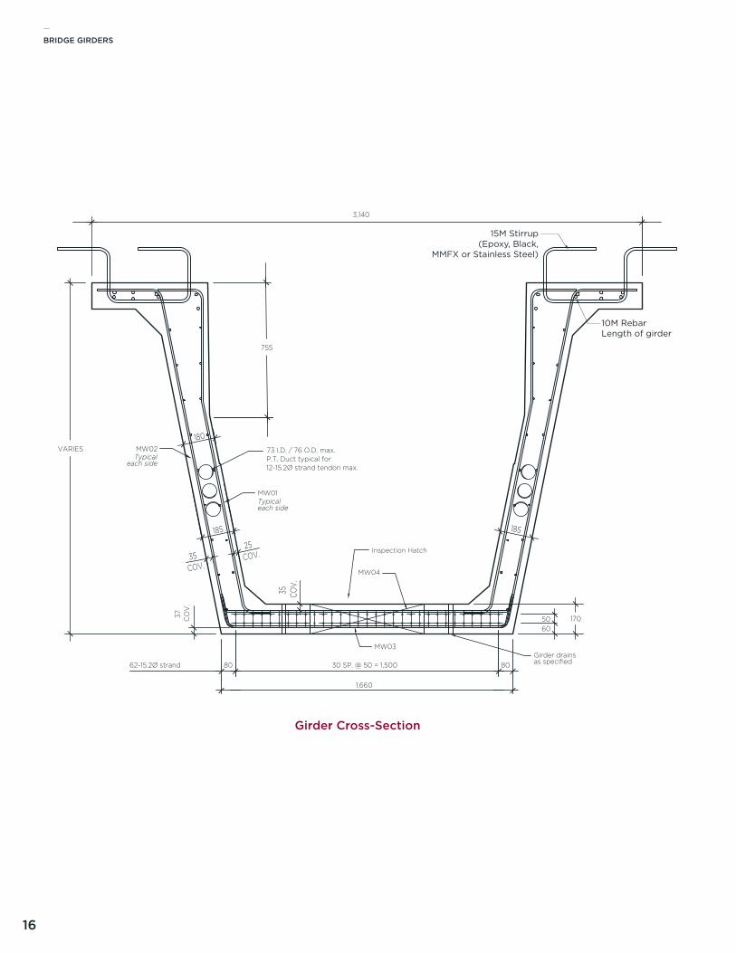
35COV.
25
185
COV.
185
180
37 CO
V.
35 COV.
MW01
MW02Typical
each side
Typicaleach side
30 SP. @ 50 = 1,500
1,660
8062-15.2Ø strand
3,140
80
MW03
MW04
73 I.D. / 76 O.D. max.
Girder drainsas specified
P.T. Duct typical for12-15.2Ø strand tendon max.
Inspection Hatch
VARIES
755
1706050
15M Stirrup(Epoxy, Black,
MMFX or Stainless Steel)
10M RebarLength of girder
Girder Cross-Section
_BRIDGE GIRDERS
17
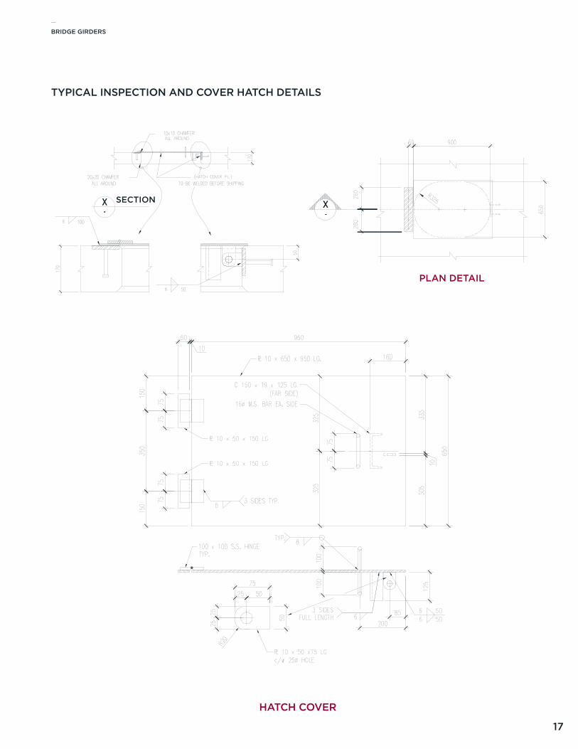
TYPICAL INSPECTION AND COVER HATCH DETAILS
PLAN DETAIL
SECTION
HATCH COVER
_BRIDGE GIRDERS
18
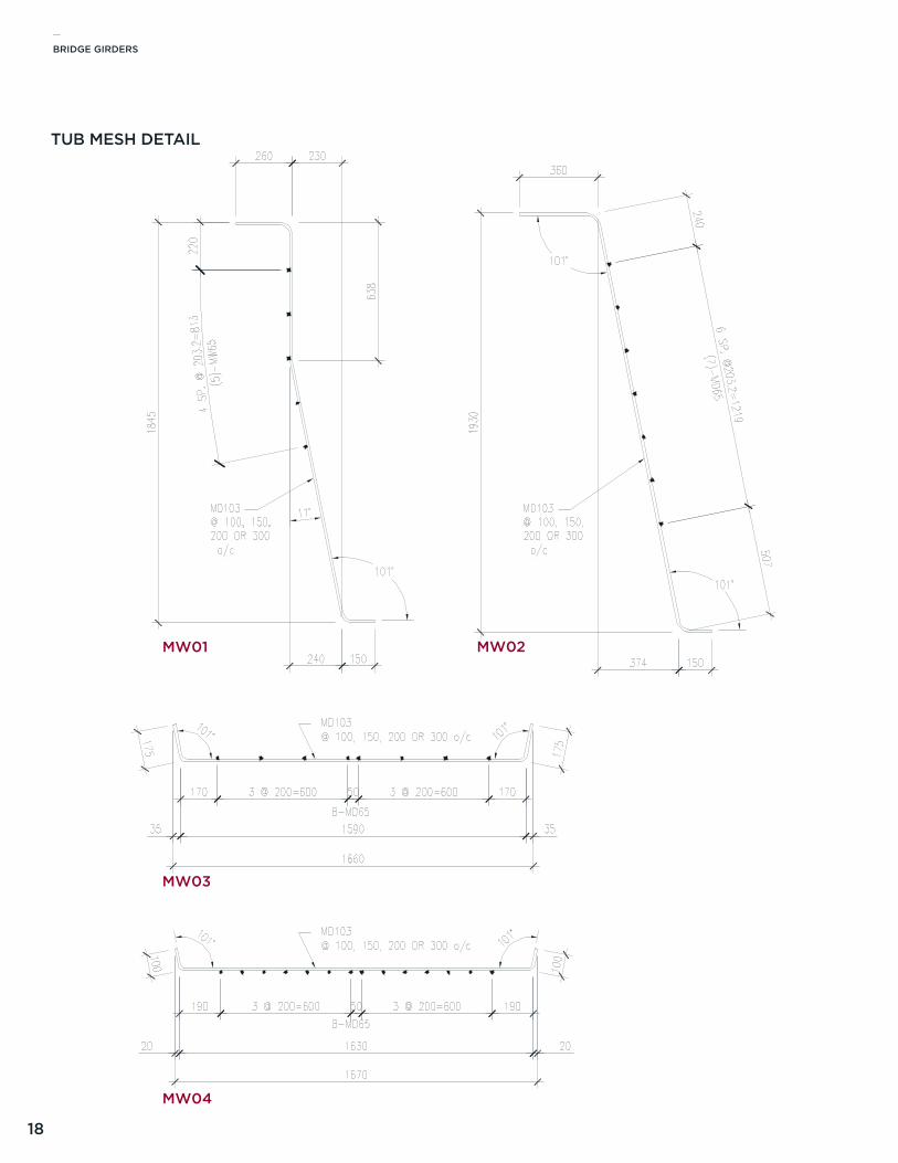
TUB MESH DETAIL
MW01 MW02
MW03
MW04
_BRIDGE GIRDERS
19
ConcreteThe span capability diagrams were developed using a 28-day minimum concrete strength of ƒ'c = 70MPa. The unit weight of concrete was assumed to be 2,450kg/m³. The concrete may contain silica fume with air entrainment of 5% to 8%.
The modulus of elasticity of concrete was calculated using the formula:
The minimum concrete release strength was assumed to be 45MPa. The concrete deck minimum 28-day strength was assumed to be 35MPa.
Prestressing StrandThe prestressing strand is 15mm in diameter, uncoated, seven-wire, low relaxation strand, meeting the requirements of aSTM a416, Grade 1860, with an area of 140mm2.
Initial jacking force is 75% Apƒpu = 195kN
End stresses were not checked for all span conditions. They may be controlled by debonding selected strands at the ends of the girders or by deflected strand.
TYPICAL APPLICATIONS
•Road bridges•Pedestrian bridges•Rail bridges
SINGLE VOID BOX GIRDERS
MATERIAL PROPERTIES
Lane Loada uniformly distributed load of 9kN/m, that is 3.0m wide as a lane load, superimposed with a Cl 800 truck, with each axle reduced to 80%
Truck Loada Cl 800 truck load, including a 25% dynamic load allowance
Dead LoadsDead loads considered to act on the untopped section are:
•Girder self weight•125mm thick deck
Superimposed Dead LoadsDead loads considered to act on the topped section are:
•90mm thick asphalt•Railing and curbs
(13kN/m total load per bridge)
Lanesa lane width of 3.3m, and the width of the bridge was calculated as:
•(# of lanes x lane Width) + 2 x 0.5m•Multi-lane reduction factor
(CaN/CSa-S6, Clause 3.8.4.2)
Prestress Lossesassumed average values of prestress losses:
•Initial losses = 8%•Final losses = 20%
Allowable Stresses
SERvICE
•Tension stresses at the bottom of the section at midspan are limited to
0.4 ƒ 'c•Compressive stress is not limited at
service, although the ratio c:dp is limited to 0.5
RElEaSE aND HaNDlING
•Tension stresses are limited to 0.5 ƒ 'ci (CaN/CSa-S6, Clause 8.8.4.6)
•Compressive stresses are limited to 0.6ƒ 'ci
DESIGN CRITERIA
The span capability charts were developed in accordance with the CaN/CSa-S6 Canadian Highway Bridge Design Code. Simple spans were assumed for all loads Calculations were done for interior girders.
13
17
21
25
29
33
37
41
45
20.0 22.5 25.0 27.5 30.0 32.5 35.0 37.5 40.0
Nu
mb
er o
f 15
mm
Dia
met
er S
tran
ds
Simple Span (m)
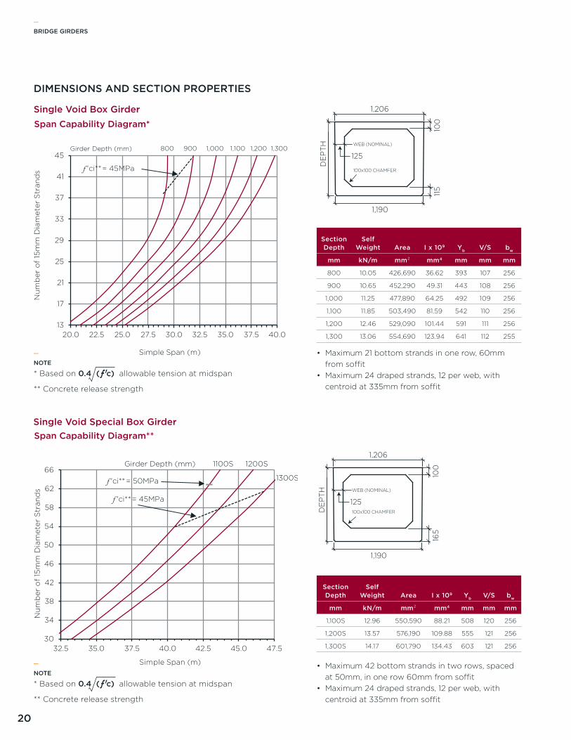
Span Capability Diagram*
Girder Depth (mm) 1,3001,2001,1001,000900
f 'ci** = 45MPa
800
30
34
38
42
46
50
54
58
62
66
32.5 35.0 37.5 40.0 42.5 45.0 47.5
Nu
mb
er o
f 15
mm
Dia
met
er S
tran
ds
Simple Span (m)
Span Capability Diagram**
Girder Depth (mm)
1300S
1200S1100S
f 'ci** = 45MPa
f 'ci** = 50MPa
_BRIDGE GIRDERS
20
DIMENSIONS AND SECTION PROPERTIES
Section Depth
Self Weight Area I x 109 Yb V/S bw
mm kN/m mm² mm4 mm mm mm
800 10.05 426,690 36.62 393 107 256
900 10.65 452,290 49.31 443 108 256
1,000 11.25 477,890 64.25 492 109 256
1,100 11.85 503,490 81.59 542 110 256
1,200 12.46 529,090 101.44 591 111 256
1,300 13.06 554,690 123.94 641 112 255
Section Depth
Self Weight Area I x 109 Yb V/S bw
mm kN/m mm² mm4 mm mm mm
1,100S 12.96 550,590 88.21 508 120 256
1,200S 13.57 576,190 109.88 555 121 256
1,300S 14.17 601,790 134.43 603 121 256
Single Void Box Girder
Single Void Special Box Girder
1,206
WEB (NOMINAL)
100x100 CHAMFER
1,190
100
DE
PT
H
115
125
WEB (NOMINAL)
100x100 CHAMFER
1,206
1,190
100
165
DE
PT
H
125
1,206
WEB (NOMINAL)
100x100 CHAMFER
1,190
100
DE
PT
H
115
125
WEB (NOMINAL)
100x100 CHAMFER
1,206
1,190
100
165
DE
PT
H
125
• Maximum 21 bottom strands in one row, 60mm from soffit
• Maximum 24 draped strands, 12 per web, with centroid at 335mm from soffit
NOTE
* Based on 0.4 (ƒ ' c) allowable tension at midspan
** Concrete release strength
_
NOTE
* Based on 0.4 (ƒ ' c) allowable tension at midspan
** Concrete release strength
_• Maximum 42 bottom strands in two rows, spaced
at 50mm, in one row 60mm from soffit• Maximum 24 draped strands, 12 per web, with
centroid at 335mm from soffit
_BRIDGE GIRDERS
21
ConcreteThe 28-day minimum concrete strength is ƒ'c = 35MPa. The unit weight of concrete was assumed to be 2,450kg/m³. The concrete contains silica fume with air entrainment of 5% to 8%.
The modulus of elasticity of concrete was calculated using the formula:
The minimum concrete release strength was assumed to be 27MPa.
Prestressing StrandThe prestressing strand is 15mm in diameter, uncoated, seven-wire, low relaxation strand, meeting the requirements of aSTM a416 , Grade 1860, with an area of 140mm2.
Initial jacking force is 71% Apƒpu = 185kN
CAN/CSA S6-06
Lane Loada uniformly distributed load of 9kN/m, that is 3.0m wide as a lane load, superimposed with a Cl 750 truck, with each axle reduced to 80%
Truck Loada Cl 750 truck load, including a 25% dynamic load allowance
Load Factors•1.2D + 1.5D (surfacing) + 1.7l
Superimposed Dead LoadsDead loads considered to act on the topped section are:
•80mm thick asphalt
TYPICAL APPLICATIONS
•Road bridges•Pedestrian bridges•Pipeline crossings•agricultural crossings
_
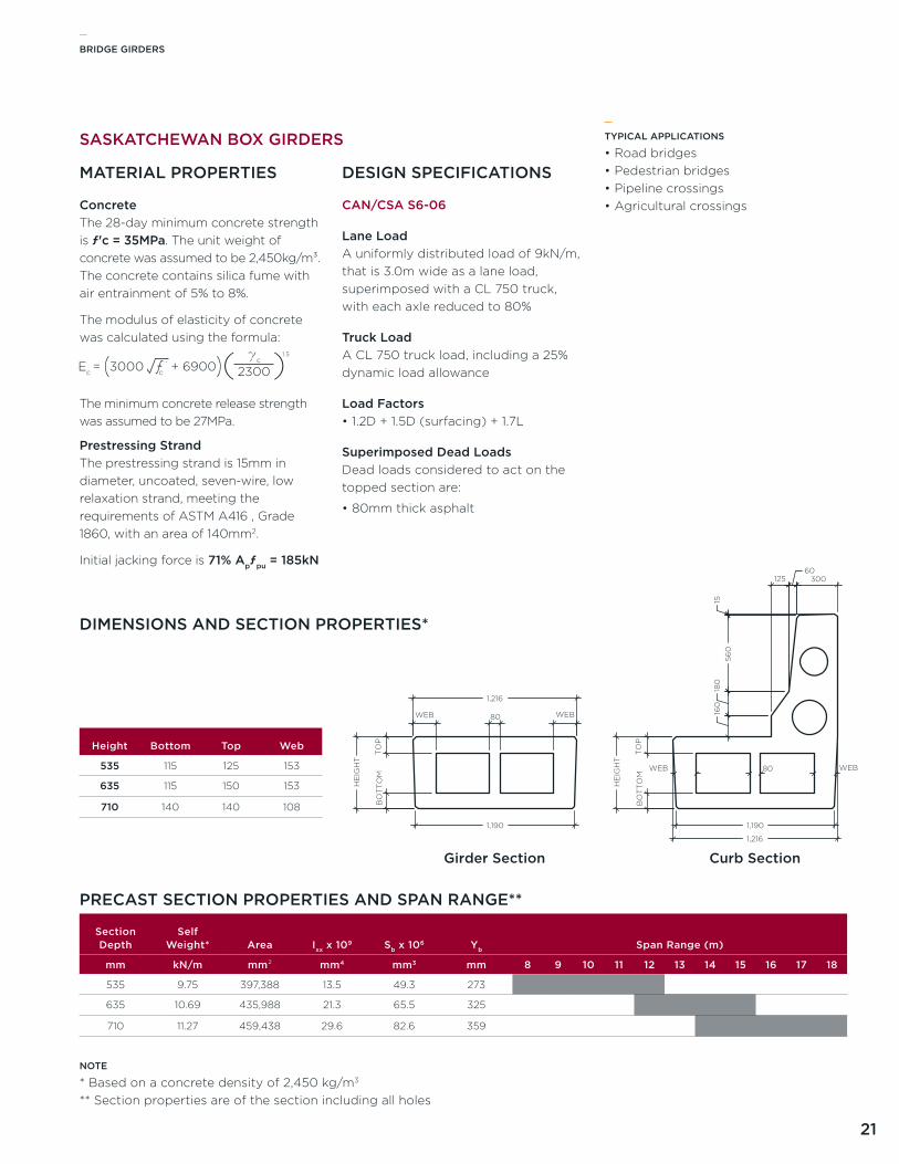
SASKATCHEWAN BOX GIRDERS
MATERIAL PROPERTIES DESIGN SPECIFICATIONS
DIMENSIONS AND SECTION PROPERTIES*
PRECAST SECTION PROPERTIES AND SPAN RANGE**
Section Depth
Self Weight* Area Ixx x 109 Sb x 106 Yb Span Range (m)
mm kN/m mm² mm4 mm3 mm 8 9 10 11 12 13 14 15 16 17 18
535 9.75 397,388 13.5 49.3 273
635 10.69 435,988 21.3 65.5 325
710 11.27 459,438 29.6 82.6 359
Height Bottom Top Web
535 115 125 153
635 115 150 153
710 140 140 108
NOTE
* Based on a concrete density of 2,450 kg/m3
** Section properties are of the section including all holes
Girder Section Curb Section
1,216
1,190
HE
IGH
T
TO
PB
OT
TO
M
80WEB WEB
1,216
1,190
HE
IGH
T
TO
PB
OT
TO
M
80WEB WEB
160
180
560
15
12560
300
_BRIDGE GIRDERS
22
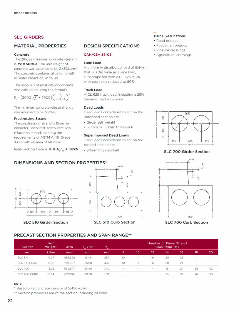
ConcreteThe 28-day minimum concrete strength is ƒ'c = 50MPa. The unit weight of concrete was assumed to be 2,450kg/m³. The concrete contains silica fume with air entrainment of 5% to 8%.
The modulus of elasticity of concrete was calculated using the formula:
The minimum concrete release strength was assumed to be 30MPa.
Prestressing StrandThe prestressing strand is 15mm in diameter, uncoated, seven-wire, low relaxation strand, meeting the requirements of aSTM a416, Grade 1860, with an area of 140mm2.
Initial jacking force is 70% Apƒpu = 182kN
CAN/CSA S6-06
Lane Loada uniformly distributed load of 9kN/m, that is 3.0m wide as a lane load, superimposed with a Cl 625 truck, with each axle reduced to 80%
Truck Loada Cl 625 truck load, including a 25% dynamic load allowance
Dead LoadsDead loads considered to act on the untopped section are:
•Girder self weight•125mm or 150mm thick deck
Superimposed Dead LoadsDead loads considered to act on the topped section are:
•80mm thick asphalt
TYPICAL APPLICATIONS
•Road bridges•Pedestrian bridges•Pipeline crossings•agricultural crossings
_
SLC GIRDERS
MATERIAL PROPERTIES DESIGN SPECIFICATIONS
PRECAST SECTION PROPERTIES AND SPAN RANGE**
DIMENSIONS AND SECTION PROPERTIES*
SectionSelf
Weight* Area Ixx x 109 Yb
Number of 15mm StrandSpan Range (m)
mm kN/m mm² mm4 mm 8 10 12 14 16 18 20
SlC 510 10.27 436,329 12.46 259 10 14 16 20 26 - -
SlC 510 CURB 16.56 703,767 55.68 442 10 14 16 20 24 - -
SlC 700 13.05 554,547 30.96 340 - - - 18 24 28 32
SlC 700 CURB 19.34 821,984 98.70 531 - - - 16 22 26 30
SLC 510 Girder Section SLC 700 Girder Section
510
245
265
Ø279
1190 1190
TYP.
222 373 373 222
700
370
330
295 600 295
SLC 510 Curb Section SLC 700 Curb Section
510
435
700
435
11901190
55545
415
20
40
55545
415
20
40
Ø435TYP.
SLC 510 Girder Section SLC 700 Girder Section
510
245
265
Ø279
1190 1190
TYP.
222 373 373 222
700
370
330
295 600 295
SLC 510 Curb Section SLC 700 Curb Section
510
435
700
435
11901190
55545
415
20
40
55545
415
20
40
Ø435TYP.
SLC 510 Girder Section SLC 700 Girder Section
510
245
265
Ø279
1190 1190
TYP.
222 373 373 222
700
370
330
295 600 295
SLC 510 Curb Section SLC 700 Curb Section
510
435
700
435
11901190
55545
415
20
40
55545
415
20
40
Ø435TYP.
NOTE
* Based on a concrete density of 2,450kg/m3
** Section properties are of the section including all holes
_
_BRIDGE GIRDERS
23
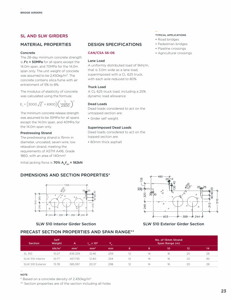
ConcreteThe 28-day minimum concrete strength is ƒ'c = 50MPa for all spans except the 14.0m span, and 70MPa for the 14.0m span only. The unit weight of concrete was assumed to be 2,450kg/m³. The concrete contains silica fume with air entrainment of 5% to 8%.
The modulus of elasticity of concrete was calculated using the formula:
The minimum concrete release strength was assumed to be 35MPa for all spans except the 14.0m span, and 40MPa for the 14.0m span only.
Prestressing StrandThe prestressing strand is 15mm in diameter, uncoated, seven-wire, low relaxation strand, meeting the requirements of aSTM a416, Grade 1860, with an area of 140mm2.
Initial jacking force is 70% Apƒpu = 182kN
CAN/CSA S6-06
Lane Loada uniformly distributed load of 9kN/m, that is 3.0m wide as a lane load, superimposed with a Cl 625 truck, with each axle reduced to 80%
Truck Loada Cl 625 truck load, including a 25% dynamic load allowance
Dead LoadsDead loads considered to act on the untopped section are:
•Girder self weight
Superimposed Dead LoadsDead loads considered to act on the topped section are:
•80mm thick asphalt
TYPICAL APPLICATIONS
•Road bridges•Pedestrian bridges•Pipeline crossings•agricultural crossings
_
SL AND SLW GIRDERS
MATERIAL PROPERTIES DESIGN SPECIFICATIONS
PRECAST SECTION PROPERTIES AND SPAN RANGE**
DIMENSIONS AND SECTION PROPERTIES*
SectionSelf
Weight A Ixx x 109 Yb
No. of 15mm StrandSpan Range (m)
kN/m* mm² mm4 mm 6 8 10 12 14
Sl 510 10.27 436,329 12.46 259 12 14 16 20 28
SlW 510 Interior 10.77 457,735 12.40 254 12 14 16 22 30
SlW 510 Exterior 13.78 585,597 20.37 298 12 14 16 20 28
NOTE
* Based on a concrete density of 2,450kg/m3
** Section properties are of the section including all holes
_
SLW 510 Interior Girder Section SLW 510 Exterior Girder Section

1-877-5-aRMTEC | aRMTEC.COM
Armtec is a leading Canadian infrastructure and construction materials company combining creative engineered solutions, relevant advice, dedicated people, proven products and a national presence with a local focus on exceptional customer service.
Drawings and product details are for information and/or illustrative purposes only and may vary. Please contact your armtec representative for the most current product information.
Armtec / Products and Services / Bridge Materials / Bridge Girders / Technical Guide | 2012-11
PROD-C01-G03_TG-2012-11-E
REGIONAL SPECIFICATIONS AB / MB / SK