Embed Size (px)
Citation preview
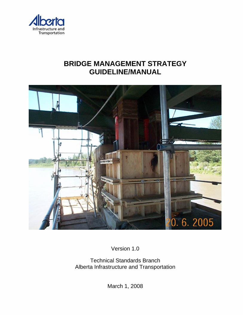
BRIDGE MANAGEMENT STRATEGY GUIDELINE/MANUAL
Version 1.0
Technical Standards Branch Alberta Infrastructure and Transportation
March 1, 2008


March 1, 2008 Preface
i
Preface to Version 1.0
Technical Standards Branch
BRIDGE MANAGEMENT STRATEGY GUIDELINE/MANUAL
(Release 1.0)
Prepared by: David Halwa, P. Eng. Regional Bridge Engineer David Robinson Regional Bridge Technologist Lloyd Atkin, P. Eng. Bridge Preservation Specialist
Printed: March 2008
COPYRIGHT 2008 GOVERNMENT OF THE PROVINCE OF ALBERTA

March 1, 2008 Preface
ii
This page was intentionally left blank.
March 1, 2008 Table of Contents
iii
Table of Contents 1.0 Introduction .............................................................................................................................1 2.0 General ...................................................................................................................................2
2.1 Timber Coring Strategy ...........................................................................................................2 3.0 Standard Bridges ....................................................................................................................3
3.1 Treated Timber Bridges ..........................................................................................................3 3.1.1 Service Life of Caps, Piles, Stringer, Subdeck and Stripdeck.........................................3 3.1.2 Strategies ........................................................................................................................3
3.2 Standard Precast Concrete Bridges with Treated Timber Substructures................................5 3.2.1 Service Life of Caps, Piles and Girders...........................................................................5 3.2.2 Strategies ........................................................................................................................5
3.3 Standard Precast Concrete Girder Bridges c/w Steel and/or Concrete Substructures ...........8 3.3.1 Deck Treatment Strategies..............................................................................................8 3.3.2 Bridge Rail Strategies......................................................................................................9 3.3.3 Superstructure Replacement Strategies .........................................................................9
4.0 Major Bridges ........................................................................................................................10 4.1 Timber Elements in Major Bridges ........................................................................................10 4.2 Deck Treatments and Rehabilitations ...................................................................................10
4.2.1 Strategies ......................................................................................................................10 4.3 Bridge Rail and Approach Rail ..............................................................................................13
4.3.1 Strategies ......................................................................................................................13 4.4 Deck Joints............................................................................................................................14
4.4.1 Strategies ......................................................................................................................14 4.5 Bridge Painting – Through and Pony Trusses ......................................................................16
4.5.1 Strategies ......................................................................................................................16 4.6 Bridge Painting – Deck Trusses and Steel Girder Bridges ...................................................17
4.6.1 Strategies ......................................................................................................................17 5.0 Culverts .................................................................................................................................19
5.1.1 Strategies ......................................................................................................................19 6.0 Figures ..................................................................................................................................23
6.1 SK1-Treated Timber Pile Repair With H-Iron Section...........................................................23 6.2 SK2-Treated Timber Pile Repair With Grouted Pipe Pile......................................................24 6.3 SK3 – Timber Stringer Repair with Channel Section ............................................................25 6.4 SK4 –Precast Connector Pocket Repair ...............................................................................26 6.5 SK5 Prestress Concrete Girder Connector Pocket Repair....................................................27 6.6 SK6 –Retrofit Plug for Deck Joint Repairs ............................................................................28 6.7 SK7 –Cover Plated Deck Joint Repair ..................................................................................29
March 1, 2008 Table of Contents
iv
This page was intentionally left blank.

March 1, 2008 Bridge Management Strategy Guideline/Manual
Page 1
1.0 Introduction The aging inventory of bridges and culverts on the Provincial public roadway system is a major concern. Given that the design life of standard bridges and culverts is 50 years and 75 years for major bridges, it is important that these structures be properly managed and maintained to ensure they reach their full life. The estimated current value of the provincial bridge system is over $8,000,000,000 and even if 1 percent of the system requires premature replacement the cost to the economy is enormous. This manual was developed to primarily assist Department Bridge staff in the planning and scheduling of bridge maintenance, rehabilitation and replacement activities. Typical management/maintenance strategies are outlined for the various structure types on the roadway network. The strategies have been developed with the view of maximising the return on the investment in the structure. It should be recognised that modifications to the suggested strategies may be necessary to accommodate site specific concerns or limitations.

March 1, 2008 Bridge Management Strategy Guideline/Manual
Page 2
2.0 General
2.1 Timber Coring Strategy Coring of timber elements is an effective method of determining the presence of rot. It is also a tool that can be used in forecasting the remaining service life of a bridge, and in helping to determine maintenance and construction requirements. The BIM Level 2 Manual - Timber Coring chapter provides detailed information on how and when a timber coring inspection should be undertaken. This section provides guidance of what actions to take when the results of a timber coring inspection are known and low element ratings have been found. It is acknowledged that any recommended action is very site specific but general parameters will be of benefit in formulating an appropriate action. Depending upon the severity of the ratings, possible actions are:
− Monitor – elements rated 3 or 4 − Load restriction posting – elements rated 2 or 3 − Full or partial closure of bridge – elements 1 or 2 − Immediate replacement – elements rated 1
The following table provides some guidelines of possible actions:
Element Element Rating Recommended Strategy Piers
Pier cap or pile 4 Consider reducing BIM inspection cycle Pier cap or pile 3 Reduce BIM inspection cycle to 12 months.
Consider replacing caps within 3 years. Pier cap or pile 2 Monitor on a maximum 6 month cycle. Consider
replacing element within one year. Pier cap or pile 1 Take immediate action to protect traffic, consider
bridge closure. Undertake emergency replacement.
Abutments Abutment cap or
pile 4 Review condition on regular BIM inspection
cycle Abutment cap or
pile 3 Consider reducing BIM inspection cycle.
Consider replacing caps within 3 years. Abutment cap or
pile 2 Monitor on a maximum 6 month cycle. Consider
replacing element within one year. Abutment cap or
pile 1 Take immediate action to protect traffic, consider
bridge closure. Undertake emergency replacement.

March 1, 2008 Bridge Management Strategy Guideline/Manual
Page 3
3.0 Standard Bridges
3.1 Treated Timber Bridges There are a small number of standard treated timber bridges in service on Provincial highways and a significant number in service on local roads. The design life of these structures was 50 years and experience has shown that the actual life of these structures can vary from 30 to 60 years. There are various components in these structures that will not last the design life of the structure and these components will require either repair and/or replacement during the life of the structure.
3.1.1 Service Life of Caps, Piles, Stringer, Subdeck and Stripdeck − Treated timber caps generally provide between 30 and 40 years of service and
cap replacement is likely required to obtain 50 years of service from the structure.
− Treated timber piles generally provide between 50 and 60 years of service and repair or replacement of individual piles may be required to extend the life of the structure.
− Treated timber stringers generally provide between 50 and 60 years of service and repair or replacement of individual stringers may be required to extend the life of the structure.
− Treated timber subdecks generally provide between 50 and 60 years of service and partial replacement of the subdeck is likely to be required to extend the life of the structure. (Note: For major bridges, full replacement of the subdeck may be an option.)
− Timber stripdecks (treated and untreated) generally provide 10 years of life, but this will vary depending upon service conditions. Partial or full replacement of the stripdeck will be required to extend the life of the structure.
3.1.2 Strategies
1. Treated Timber Cap Replacement Treated timber caps are routinely replaced between year 30 and year 40 and will extend the service life of the structure 20 to 30 years provided that the treated timber piles, stringers and subdeck are in adequate condition or can be brought to adequate condition economically.
a) depending upon material availability, replacement with a timber cap would be the preferred option
b) replacement with a steel H-pile cap is an option, but is likely to be more expensive than timber. A steel cap could be considered for the situation where the cap replacement is urgent and timber is not readily available.
March 1, 2008 Bridge Management Strategy Guideline/Manual
Page 4
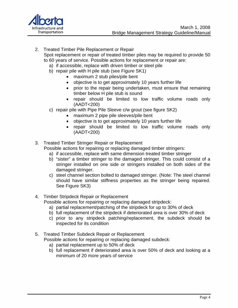
2. Treated Timber Pile Replacement or Repair Spot replacement or repair of treated timber piles may be required to provide 50 to 60 years of service. Possible actions for replacement or repair are:
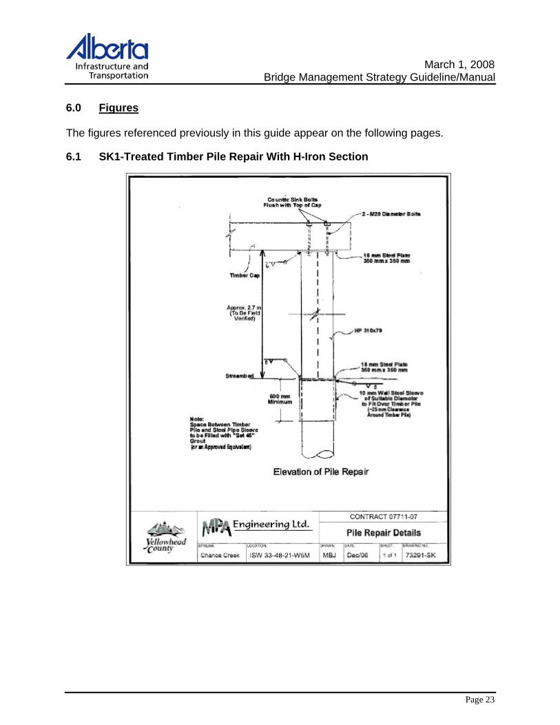
a) if accessible, replace with driven timber or steel pile b) repair pile with H pile stub (see Figure SK1)
• maximum 2 stub piles/pile bent • objective is to get approximately 10 years further life • prior to the repair being undertaken, must ensure that remaining
timber below H pile stub is sound • repair should be limited to low traffic volume roads only
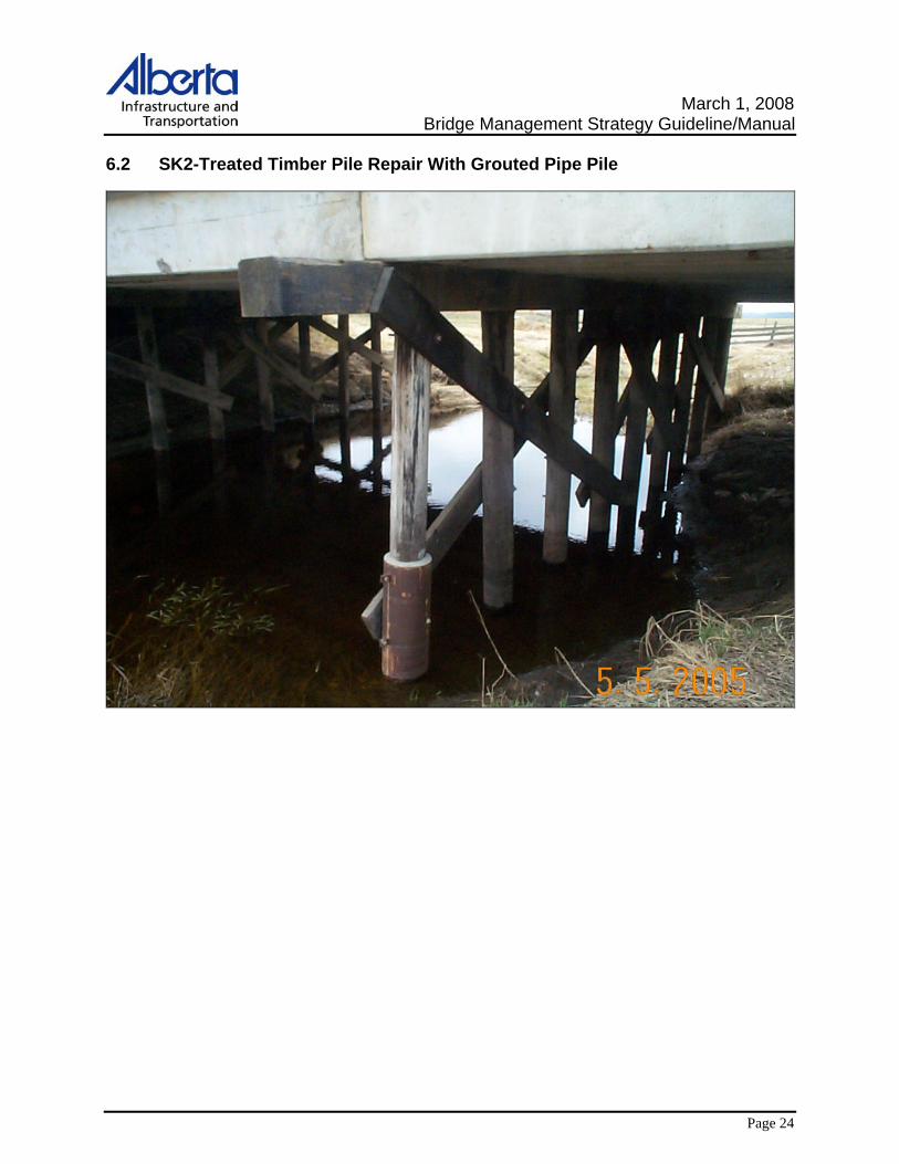
(AADT<200) c) repair pile with Pipe Pile Sleeve c/w grout (see figure SK2)
• maximum 2 pipe pile sleeves/pile bent • objective is to get approximately 10 years further life • repair should be limited to low traffic volume roads only
(AADT<200)
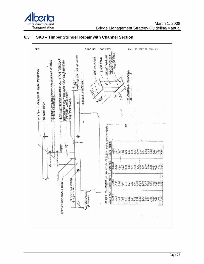
3. Treated Timber Stringer Repair or Replacement Possible actions for repairing or replacing damaged timber stringers:
a) if accessible, replace with same dimension treated timber stringer b) “sister” a timber stringer to the damaged stringer. This could consist of a
stringer installed on one side or stringers installed on both sides of the damaged stringer.
c) steel channel section bolted to damaged stringer. (Note: The steel channel should have similar stiffness properties as the stringer being repaired. See Figure SK3)
4. Timber Stripdeck Repair or Replacement
Possible actions for repairing or replacing damaged stripdeck: a) partial replacement/patching of the stripdeck for up to 30% of deck b) full replacement of the stripdeck if deteriorated area is over 30% of deck c) prior to any stripdeck patching/replacement, the subdeck should be
inspected for its condition
5. Treated Timber Subdeck Repair or Replacement Possible actions for repairing or replacing damaged subdeck:
a) partial replacement up to 50% of deck b) full replacement if deteriorated area is over 50% of deck and looking at a
minimum of 20 more years of service

March 1, 2008 Bridge Management Strategy Guideline/Manual
Page 5
3.2 Standard Precast Concrete Bridges with Treated Timber Substructures There is a significant inventory of standard precast concrete girder bridges with treated timber substructures that were constructed in the 1950’s, 1960’s and early 1970’s. The design life of these structures was 50 years and general guidelines or criteria for the repair or replacement of these bridge structures are required as many of these structures are approaching the end of their service life.
3.2.1 Service Life of Caps, Piles and Girders − Treated timber caps generally provide between 30 and 40 years of service and
cap replacement is likely required to obtain 50 years of service from the structure.
− Treated timber piles generally provide between 50 and 60 years of service and repair or replacement of individual piles may be required to extend the life of the structure.
− Precast girders provide between 50 and 60 years of service and repair or replacement of individual girders may be required to extend the life of the structure.
3.2.2 Strategies General guidelines are required for the repair or replacement of timber substructure elements including caps and piles.
1. Treated Timber Cap Replacement
Treated timber caps are routinely replaced between year 30 and year 40 and will extend the service life of the structure 20 to 30 years provided that the treated timber piles and precast girders are in good condition.
a) replacement with treated timber caps is the usual option where the structure has a limited remaining life
b) replacement with steel caps should be considered if the piles and girders are in good condition and have an extended estimated remaining life of 30+ years and/or an elevation change is required
c) replacement with steel caps should be the option if the structure is on a Provincial Highway
It is acknowledged that the installation of steel caps on timber piles will require steel capitals, resulting in additional costs. A life cycle cost analysis may be required in some situations to decide on whether cap replacement is done with steel or timber.
March 1, 2008 Bridge Management Strategy Guideline/Manual
Page 6
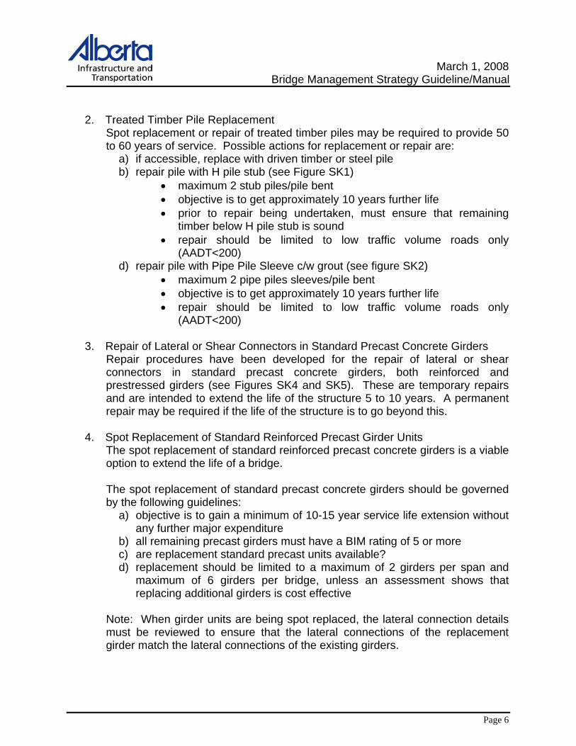
2. Treated Timber Pile Replacement Spot replacement or repair of treated timber piles may be required to provide 50 to 60 years of service. Possible actions for replacement or repair are:
a) if accessible, replace with driven timber or steel pile b) repair pile with H pile stub (see Figure SK1)
• maximum 2 stub piles/pile bent • objective is to get approximately 10 years further life • prior to repair being undertaken, must ensure that remaining
timber below H pile stub is sound • repair should be limited to low traffic volume roads only
(AADT<200) d) repair pile with Pipe Pile Sleeve c/w grout (see figure SK2)
• maximum 2 pipe piles sleeves/pile bent • objective is to get approximately 10 years further life • repair should be limited to low traffic volume roads only
(AADT<200)
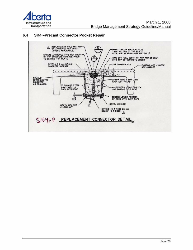
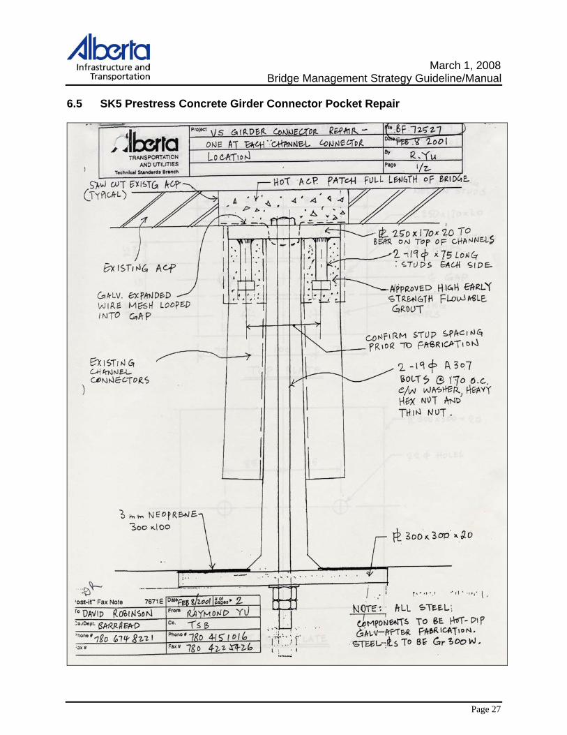
3. Repair of Lateral or Shear Connectors in Standard Precast Concrete Girders Repair procedures have been developed for the repair of lateral or shear connectors in standard precast concrete girders, both reinforced and prestressed girders (see Figures SK4 and SK5). These are temporary repairs and are intended to extend the life of the structure 5 to 10 years. A permanent repair may be required if the life of the structure is to go beyond this.
4. Spot Replacement of Standard Reinforced Precast Girder Units
The spot replacement of standard reinforced precast concrete girders is a viable option to extend the life of a bridge. The spot replacement of standard precast concrete girders should be governed by the following guidelines:
a) objective is to gain a minimum of 10-15 year service life extension without any further major expenditure
b) all remaining precast girders must have a BIM rating of 5 or more c) are replacement standard precast units available? d) replacement should be limited to a maximum of 2 girders per span and
maximum of 6 girders per bridge, unless an assessment shows that replacing additional girders is cost effective
Note: When girder units are being spot replaced, the lateral connection details must be reviewed to ensure that the lateral connections of the replacement girder match the lateral connections of the existing girders.
March 1, 2008 Bridge Management Strategy Guideline/Manual
Page 7
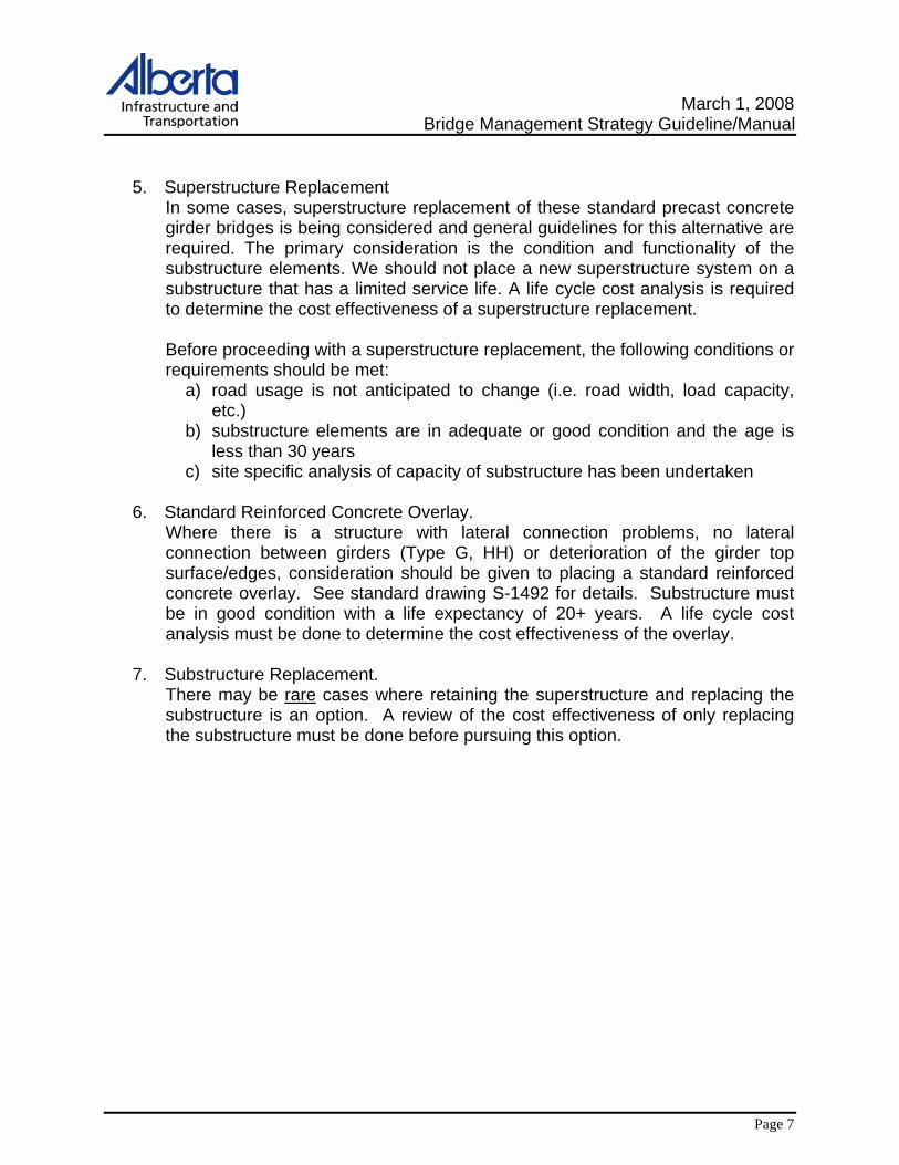
5. Superstructure Replacement In some cases, superstructure replacement of these standard precast concrete girder bridges is being considered and general guidelines for this alternative are required. The primary consideration is the condition and functionality of the substructure elements. We should not place a new superstructure system on a substructure that has a limited service life. A life cycle cost analysis is required to determine the cost effectiveness of a superstructure replacement. Before proceeding with a superstructure replacement, the following conditions or requirements should be met:
a) road usage is not anticipated to change (i.e. road width, load capacity, etc.)
b) substructure elements are in adequate or good condition and the age is less than 30 years
c) site specific analysis of capacity of substructure has been undertaken
6. Standard Reinforced Concrete Overlay. Where there is a structure with lateral connection problems, no lateral connection between girders (Type G, HH) or deterioration of the girder top surface/edges, consideration should be given to placing a standard reinforced concrete overlay. See standard drawing S-1492 for details. Substructure must be in good condition with a life expectancy of 20+ years. A life cycle cost analysis must be done to determine the cost effectiveness of the overlay.
7. Substructure Replacement.
There may be rare cases where retaining the superstructure and replacing the substructure is an option. A review of the cost effectiveness of only replacing the substructure must be done before pursuing this option.
March 1, 2008 Bridge Management Strategy Guideline/Manual
Page 8
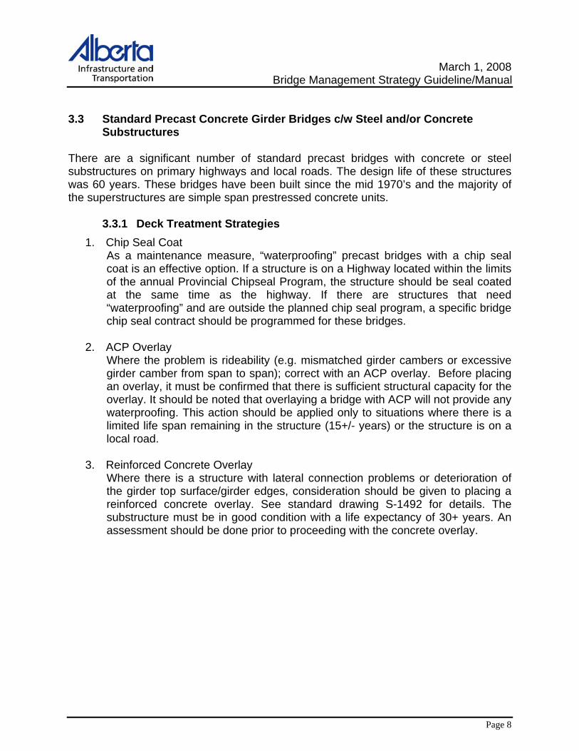
3.3 Standard Precast Concrete Girder Bridges c/w Steel and/or Concrete Substructures
There are a significant number of standard precast bridges with concrete or steel substructures on primary highways and local roads. The design life of these structures was 60 years. These bridges have been built since the mid 1970’s and the majority of the superstructures are simple span prestressed concrete units.
3.3.1 Deck Treatment Strategies 1. Chip Seal Coat
As a maintenance measure, “waterproofing” precast bridges with a chip seal coat is an effective option. If a structure is on a Highway located within the limits of the annual Provincial Chipseal Program, the structure should be seal coated at the same time as the highway. If there are structures that need “waterproofing” and are outside the planned chip seal program, a specific bridge chip seal contract should be programmed for these bridges.
2. ACP Overlay Where the problem is rideability (e.g. mismatched girder cambers or excessive girder camber from span to span); correct with an ACP overlay. Before placing an overlay, it must be confirmed that there is sufficient structural capacity for the overlay. It should be noted that overlaying a bridge with ACP will not provide any waterproofing. This action should be applied only to situations where there is a limited life span remaining in the structure (15+/- years) or the structure is on a local road.
3. Reinforced Concrete Overlay Where there is a structure with lateral connection problems or deterioration of the girder top surface/girder edges, consideration should be given to placing a reinforced concrete overlay. See standard drawing S-1492 for details. The substructure must be in good condition with a life expectancy of 30+ years. An assessment should be done prior to proceeding with the concrete overlay.

March 1, 2008 Bridge Management Strategy Guideline/Manual
Page 9
4. ACP Overlay with Waterproofing Membrane
Consider ACP overlay with waterproofing membrane for use on VS, SM and SC structures. Structures on paved highways can be subject to significant applications of salt. If deterioration of the girders is starting to become a problem, an ACP overlay with waterproofing membrane may be an alternative to extending the life of the girders another 30+ years. An assessment of the structure must be done to determine that the bridge is functionally adequate and the substructure is sound with 30+ years of service. As well, the girders must be checked to confirm they have load capacity to carry the additional dead load of the ACP with waterproofing membrane. (Note: Girders designed for HS-25 loading or better, will have the capacity to carry the dead load if analysed using a load rating evaluation.)
3.3.2 Bridge Rail Strategies Rail upgrades are discussed in the Major Bridge section of this manual. The issues discussed there, are applicable to precast concrete bridges.
3.3.3 Superstructure Replacement Strategies
1. Spot Replacement of Girders Spot replacement of precast reinforced girders should follow the guidelines as outlined in the Standard Precast Girders with Treated Timber Substructure section. Spot replacement of prestressed girders should be on an as required basis. When replacing a prestressed unit, the substructure should have an anticipated minimum remaining life of 10-15 years. As well, the location of connector pockets of the existing prestressed girders must be confirmed to ensure that the replacement unit will match.
2. Superstructure Replacement Where superstructure replacement of standard precast concrete girders is being considered, the primary consideration should be the condition and functionality of the substructure elements. We should not place a new superstructure system on a substructure that has a limited service life. A life cycle cost analysis is required to determine the cost effectiveness of the superstructure replacement. Before proceeding with a superstructure replacement, the following conditions or requirements should be met:
a) road usage is not anticipated to change (i.e. road width, load capacity, etc.)
b) substructure elements are in adequate or good condition and have a remaining life of 30+ years
c) site specific analysis of capacity of substructure has been undertaken
March 1, 2008 Bridge Management Strategy Guideline/Manual
Page 10
4.0 Major Bridges
4.1 Timber Elements in Major Bridges
Major bridges may have a number of elements that are comprised of timber. There are numerous major bridges that are founded on treated timber substructures and there are a large number of truss bridges with timber decks. The management strategy for the timber piles/caps and/or timber decks on a major bridge would be similar to the strategies for a standard bridge. Refer to the Standard Bridge section for possible strategies regarding timber elements.
4.2 Deck Treatments and Rehabilitations
General guidelines may be required for each of the possible deck treatment actions. It is acknowledged that the selection of an appropriate deck rehabilitation action is very site specific and must take into account numerous variables. The entire structure should be assessed before proceeding with any deck treatment or rehabilitation.
4.2.1 Strategies Possible deck treatment alternatives include the following:
1. Chip Seal Coat
A “Temporary waterproofing” system can be used to obtain an additional 5 years or possibly 10 years before performing a major intervention. Results of CSE deck testing has shown that a chip seal coat can be effective in providing a short term reduction in corrosion activity in a concrete deck. Chip seal coat is an inexpensive solution when you are trying to extend the life of a deck a few more years. (Note: Sealing of cracks is recommended before placing chip seal coat.)
2. Asphalt Overlay
Asphalt overlays should only be used on their own where there are problems with the rideability of a deck or deterioration of a concrete deck surface through wear and a short term solution is needed. Using an asphalt overlay should be considered to address rideability only. Asphalt is not waterproof and will not protect a concrete deck from the infiltration of water and chlorides. If long term protection of the deck is warranted, then other solutions would need to be considered.

March 1, 2008 Bridge Management Strategy Guideline/Manual
Page 11
3. Hot Applied Rubberized Waterproofing System The standard waterproofing system used in Alberta is a hot applied rubberized asphalt membrane overlain with protection board and 80 mm of asphalt (Dwg. S-1443). This system has been used with good results since the mid 1980’s and should be the default system for use on all new construction. The total system should typically last 40 years before requiring replacement, with the top lift of asphalt likely requiring replacement after 20 years.
In rehabilitation situations, the waterproofing system may be a viable rehabilitation alternative. An assessment of the structure must be done to determine if the bridge can handle the additional dead load and the condition/remaining service life of the structure warrants installation of the waterproofing system.
4. Polymer Modified Asphalt (PMA) Wearing Surface
PMA has been used as a wearing surface and quasi-waterproofing membrane in urban applications. While not as effective as the rubberized waterproofing system, this alternative might be considered where high traffic volumes make it desirable to minimise the time required to rehabilitate a deck. PMA is not readily available outside of major urban centres and would not be an alternative in remote or rural locations.
5. Polymer Overlay
Polymer overlays have been used in the past as a waterproofing alternative. Rising costs have made the polymer overlay less attractive as an overlay and at the time of writing this manual, the last polymer overlay installation was in the late 1990’s. An assessment must be done on a site by site basis to determine if a polymer overlay is a viable option. In should be noted, that once a polymer overlay has started to debond, spot patching of the overlay has proved ineffective. (A practical fix, when polymer is debonding, is to sawcut the debonded areas and patch with chip seal or spray patch.)

March 1, 2008 Bridge Management Strategy Guideline/Manual
Page 12
6. Concrete Overlay Concrete overlays, with or without steel fibres, is a rehabilitation alternative that would be used when you are anticipating getting 25 to 30 years of life from a concrete deck before the next major rehabilitation. A concrete overlay would be used when a structure cannot carry the additional dead load of the 90 mm waterproofing system or increased thickness in the wearing surface could have other detrimental effects. Also, a concrete overlay would be used where it is suspected that there may be significant areas of the deck requiring repair. As a rule, a concrete overlay would first be placed when CSE deck testing shows that 20% of the deck area is either in transition or actively corroding and a second overlay considered when testing shows that 50% of the deck is active or transitioning. In addition to the CSE testing, chloride content testing should be done to determine the chloride concentrations at the various depths of the slab. If chloride contents are high enough in the vicinity of the bottom layer of reinforcing steel to initiate corrosion, a concrete overlay may not be the best solution. An assessment must be done on a site by site basis to determine if a concrete overlay is a viable option.
7. Reinforced Concrete Overlay A reinforced concrete overlay should be considered for structures where lateral connectivity problems are occurring (e.g. grout key failures). As well, a reinforced concrete overlay may be used to eliminate pier joints by making the overlay continuous and possibly eliminating abutment joints by wrapping the overlay around the end of the girders. The typical reinforced concrete overlay will have a thickness in the order of 125 mm which may be twice as thick as an existing overlay/wearing surface. An assessment of the load carrying capacity of the bridge structure must be done to determine if the structure is capable of carrying additional dead load. The structure should have a life expectancy of 30+ years. An assessment must be done on a site by site basis to determine if a reinforced concrete overlay is a viable option.
8. Deck Replacement Deck replacement is a rehabilitation option to be considered when the existing concrete deck has effectively reached the end of its life. This could be a concrete deck that is suffering from extensive deterioration/spalling, significant leakage and high CSE and/or chloride readings. If considering a deck replacement, the life expectancy of the remainder of the structure should be 35+ years. A new concrete-to-grade deck can be expected to have a life of 35 to 50 years and a new concrete deck with a 90 mm waterproofing system could be expected to have a life of 70 years. An assessment must be done on a site by site basis to determine if a deck replacement is a viable option. As part of this assessment, the roadway width should be reviewed for adequacy.
March 1, 2008 Bridge Management Strategy Guideline/Manual
Page 13
4.3 Bridge Rail and Approach Rail New standards for bridge rails and approach rail transitions were adopted in the year 2000 for new bridge construction. These new standards reflected the design requirements of the revised CSA S6 Canadian Highway Bridge Design Code. For the existing bridge inventory, there is a considerable length of bridge rail and approach guardrail that does not meet the current code requirements as it was designed and constructed for the standards of the day. These existing installations represent a significant capital expenditure that was invested with the expectation of a long service life. It is unrealistic to require replacement of all these rail systems. A decision to upgrade or replace an existing rail system is based on cost-benefit considerations to ensure a balance between safety and the effective use of rehabilitation funding. A formal economic analysis has been developed by the Department to address the upgrading of bridge and approach rails (see Roadside Design Guide). It should be noted, that this economic analysis does not take into consideration the condition of the rail and replacement may be driven by reasons other than economic ones.
4.3.1 Strategies Possible bridge rail and approach rail treatment alternatives include the following:
1. Replacement − If an existing rail and curb are in adequate condition, a cost-benefit analysis
needs to be done to determine if upgrading the rail is warranted. − If analysis indicates that upgrading is warranted, replacement would be the
option if retro-fitting of the existing rail is not feasible (e.g. existing posts have insufficient anchorage).
− If the structural condition of the rail and/or curb dictates that rehabilitation of the rail or curb is required, replacement is the preferred option.
− If a rail is being replaced, the approach guardrail and transition rail section should be upgraded to current standards.
2. Retro-fit Existing − If an existing rail and curb are in adequate condition, a cost benefit analysis
needs to be done to determine if upgrading the rail is warranted. − If analysis indicates that upgrading is warranted, retro-fit of an existing rail to
new standards should be considered if looking for a short term upgrade (less than 20 years). If looking for more than 20 years service, replacement should be considered.
− If a rail is being retro-fit, the approach guardrail and transition rail section should be upgraded to current standards as well.

March 1, 2008 Bridge Management Strategy Guideline/Manual
Page 14
3. Do Nothing − If an existing rail and curb are in adequate condition, a cost-benefit analysis
needs to be done to determine if upgrading the rail is warranted. − If the analysis indicates that upgrade of the bridge rail and/or the approach
transition is not warranted, then upgrade to current standards should not be undertaken.
4.4 Deck Joints The following are general guidelines for the repair or replacement of deck joints. It must be noted that the best course of action for rehabilitating a deck joint will be specific to that joint. For example, there are some deck joint types (Type III) that have been found to be ineffective and require replacement following failure of the joint. Repair or replacement actions are to take into account the type of joint, age of bridge structure, potential damage to other bridge elements due to leakage, etc.
4.4.1 Strategies Possible deck joint treatment alternatives include the following:
1. Full Joint Replacement − Typical strip seal joints can be expected to have a life span of approximately 25
years. If rehabilitating a joint of this approximate age and expecting a long service life from the structure (20+ years), then complete replacement of the joint should be considered.
− If the anchorage of a joint has failed, then complete replacement would be warranted.
− In situations where the strip seal has failed and a replacement seal cannot be purchased (i.e. particular type of seal no longer made), complete replacement may be the only option.
− Due to the expensive nature of a deck joint replacement, consideration should be given to the possibility of eliminating the joint entirely. Possible alternatives include continuous reinforced concrete overlay or integral abutments.
March 1, 2008 Bridge Management Strategy Guideline/Manual
Page 15
2. Joint Repair a) Coverplated Deck Joints – common repairs to loose cover plate sections include:
• tightening of bolts to required torque • replacing damaged or missing bolts • installing retrofit plugs – (figure SK6) • shimming of plate sections • grouting of voids under base plates • if gap permits and the base plate is in good condition, the cover plated
joint can be re-designed as an open joint – (figure SK7)
Note: Problems with base plates, corrosion or loss of anchorage, usually indicate that replacement of the deck joint will be required in possibly 5 years or less.
b) Finger plate joints – common repairs include
• repair of broken welds • shimming of individual fingers • repairing individual fingers to provide contact with base plate • grouting of voids under base plates
Note: Finger plate joints are expensive and repair of the joint should be closely reviewed before going to full replacement. c) Strip seal joints – If a strip seal joint is relatively new and the paving lip has failed, repair of the joint by recasting the nosing concrete would be the preferred option.
Note: If a Type III strip seal paving lip has failed, do not attempt to repair! Joint should be replaced with a Type I strip seal, with some urgency for safety reasons.
3. Seal Replacement − Typical strip seal joints have a life span of ~25 years, while the strip seal will
have a life span of ~15 years. If a seal has failed and the extrusion and concrete anchorage are in good condition, replacement of the seal would be the preferred rehabilitation.
− The existing joint gap needs to be reviewed as too small a gap may prevent the seal replacement.
− As previously mentioned, an important factor in deciding to replace a strip seal is the availability of the seal.
March 1, 2008 Bridge Management Strategy Guideline/Manual
Page 16
4.5 Bridge Painting – Through and Pony Trusses Currently, the Province has approximately 300 bridge sites with either through truss spans, pony truss spans or a combination of both through and pony truss spans that fall under the ownership of AIT. Of these 300 bridge sites; 71 sites are under the direct management of AIT, 9 of the bridge sites managed by AIT are pedestrian bridges, 12 of the bridge sites are on local roads, and the remaining 50 sites are on the numbered Provincial Highway system. The fabrication dates of the highway truss spans ranges from 1906 to 1969 and all of these structures have been painted as protection against corrosion. A review of the highway trusses reveals that many of the bridges have narrow roadway widths and a large number of them have load restrictions. Environmental controls and requirements have had a severe impact on the cost of painting bridges. Costs for painting through and pony trusses has increased two to three fold from the year 2000 to 2004. This increase means that the painting of a through or pony truss may cost as much as one-third to one-half the cost of a new structure. Since the majority of through and pony trusses do not meet the desired roadway standards with respect to roadway width and/or loading, it is questionable if through and pony trusses should be rehabilitated by painting. In addition, through and pony trusses can be a continual maintenance problem by being susceptible to hits by oversize loads.
4.5.1 Strategies The following guidelines are offered as a rehabilitation strategy for through and pony trusses:
− Keep trusses in service as long as possible with spot rehabilitations (e.g. truss member replacement, spot painting).
− Do not undertake re-painting unless an assessment clearly demonstrates the cost benefit of doing so.
March 1, 2008 Bridge Management Strategy Guideline/Manual
Page 17
4.6 Bridge Painting – Deck Trusses and Steel Girder Bridges
In approximately 1975, the Department switched to using weathering steel in steel girders and trusses which eliminated the need for painting of new bridges. The result of this is the number of deck truss structures or steel girder bridges that may require painting is a relatively fixed number (about 350 structures). This means that the age of any structures requiring painting will be at least 30+ years old and this will have a bearing on whether painting will be a cost effective solution. It is acknowledged that the recommendation for any paint system alternatives is very site specific and the following should be used as guidelines only.
4.6.1 Strategies Possible paint system treatment alternatives include the following:
1. Full Paint System Replacement − Full paint system replacement may be expected to have a service life of ~20
years before initial failure of the paint becomes evident. − Full paint system replacement should only be considered if there is a long
service life, say 30+ years, remaining in the structure. − The paint coating on deck trusses tends to fail in all areas except for the floor
system in the protected area underneath the deck and is a candidate for complete paint replacement. Traffic creates a salt laden mist which is thrown into the air around the truss and is blown back by the wind into the truss members. The upper surfaces will fail more rapidly because debris collects on these surfaces, but failure will soon be quite general. Partial repair on these structures is usually so extensive, that for all practical purposes, a complete paint job should be considered in most cases.
− Before a full paint replacement is undertaken, an assessment of the structure must be undertaken including a full life cycle cost analysis.

March 1, 2008 Bridge Management Strategy Guideline/Manual
Page 18
2. Partial Paint System Replacement − Partial paint replacement should be expected to provide ~20 years of protection
before initial failure of the paint protection. − Because of the way paint fails on steel girder structures, partial paint system
replacement can be a cost effective option with steel girder structures. − Generally the paint failure mode on steel girder bridges is for the paint to begin
to fail on the edges of the bottom flange of the exterior girder. It then starts to fail on the fascia of the web of the exterior girder. Failure moves to the under side of the bottom flange of the exterior girder. This underside failure of the bottom flange then shows up on the interior girders progressively towards the centre of the structure. Generally the last paint to fail is in the upper protected area between the girders. This mode of failure for steel girders can dictate partial paint replacement. Typical partial repair on a girder structure would be to paint the fascia girder webs and bottom flanges of the exterior girders. Depending upon the extent of paint decay, the bottom flanges of some interior girders may require painting. As well, the ends of the interior girders at deck joints will likely require painting.
− Before a partial replacement is undertaken, an assessment of the structure must be completed including a full life cycle cost analysis.
3. Top Coating of Existing Paint Systems − Top coating of the existing paint system was a very attractive alternative
because it did not require the removal of the existing paint, which typically contained lead. However, the window for top coating is relatively small and can be easily missed.
− In general, the paint on most of the painted structures has deteriorated to the point where top coating is no longer a viable option.
− If applied at the correct time, top coating could be expected to extend the life of the existing paint by ~15 years. If applied too late, top coating may last as a little as 5 years.
− Top coating may still be an effective option where there are only isolated areas requiring painting and you are looking at providing protection for a short period of time (5 to 10 years).
4. Weathering Steel − There are instances where weathering steel girders have been losing section
due to constant wetting. An example of this situation has been the ends of steel girders located underneath leaking deck joints. The constant flushing of the weathering steel with water will lead to section loss and painting these areas may be a cost effective solution to preventing the section loss.
March 1, 2008 Bridge Management Strategy Guideline/Manual
Page 19
5.0 Culverts There are approximately 8000 bridge size culverts on the roadway system in Alberta. This accounts for the majority of the bridge size structures in our inventory. Of these 8000 structures, about 4% of the culverts are rigid structures (majority made from concrete) and the remainder are flexible soil-metal structures. Soil-metal structures are generally cheaper than rigid culverts, but are susceptible to more problems. These guidelines for culverts will mainly focus on maintenance and rehabilitation options for flexible culverts.
5.1.1 Strategies Possible management strategies with respect to culverts include the following:
1. Monitoring − Monitoring should be considered as an option when considering a repair of a
structure. Soil-metal culverts have virtually no ability to resist movements in the soil around them. In cases where a culvert has been installed in a poor foundation in unstable fills or with a poor structural backfill envelope, it may experience problems and start to deform with the movement of the soil. However, once the consolidation of the foundation or soil has occurred, the movement usually stops. If the culvert has not failed, but has been able to reach a state of equilibrium, it can often function for many years without further problems.
− When monitoring a structure, it is vital to note if any movements are taking place and to accurately note and date all reference points. A Level 2 inspection should be done to provide an initial set of reference/benchmark measurements.
− As part of this, when a new culvert is installed, it is important that ‘As Constructed’ span and rise dimensions be recorded at the ends, quarter and mid-points. Having this information as a base is extremely valuable when assessing the condition of a culvert at a future date.

March 1, 2008 Bridge Management Strategy Guideline/Manual
Page 20
2. Installation of Struts − Installation of struts can quite often be the cheapest option and can be
considered to be a repair that, depending upon the condition of the culvert, will provide 5 or more years of additional life.
− Strutting of a culvert should be considered when the amount of roof sag is approaching 15%.
− If a culvert has reached the stage of reverse curvature in the roof plates, strutting is may be the only rehabilitation option available. (Note: There have instances where it was possible to jack the culvert back into the correct shape.)
− The preferred material for strutting is steel (see Dwg. S-1620). − Strutting with timber is also an option. However, due to the size of the individual
timber pieces, handling of the timber components may become problematic. − Strutting is not suitable for culvert sites which may be subjected to drift and/or
flowing ice conditions unless a drift catcher can be installed.
3. Installation of Concrete Floor − A concrete floor should be considered as a rehabilitation option for repairing
severe perforations or deterioration of the invert. − A concrete floor should be considered as an option for reinforcing cracked
seams and sidewall deformation in arch culverts. − Installation of a concrete floor may reduce the hydraulic capacity of a culvert. − Extent of the corrosion of the barrel will dictate whether a concrete floor is an
effective repair. − Unless a life cycle cost analysis indicates otherwise, there should be a minimum
of 15 years remaining life in the rest of the culvert before undertaking the concrete floor repair.
− Strutting can be used in conjunction with the concrete floor in certain situations. − An assessment should be done before undertaking the repair.
4. Shotcrete or Concrete Repair of Seams − If a culvert has cracked longitudinal seams in the sidewall, repair with a
shotcrete/concrete beam is an option. − Remaining elements of the culvert must be in adequate condition (rating 5 or
more). − Deflections should be limited to no more than 15%. − Other methods for repairing cracked seams have been tried (e.g. bolted plate,
welded seams), but in general they have not been as cost effective as shotcrete/concrete beams.
− An assessment should be done before undertaking the repair.

March 1, 2008 Bridge Management Strategy Guideline/Manual
Page 21
5. Installation of Liner − For culverts that are not badly deformed but which have several cracked seams
and/or corrosion problems, lining may be a suitable repair. − Lining is considered a permanent fix and can be expected to extend the life of a
culvert by 30+ years. − Main disadvantage of using a culvert liner is the reduced hydraulic capacity of
the culvert. This may have adverse effects on land upstream of the culvert, increased velocities at the outlet of the culvert and fish passage.
− Liners are usually sized to just pass the point of greatest deflection. If there is a local deflection, it may be possible to jack the culvert back into shape, allowing a larger liner to be used.
− If the existing pipe is deteriorated for only a segment of its length (less than ½ it’s length), use of a partial liner may be the most economical solution.
− If an existing pipe has deterioration for more than ½ the length, lining of the culvert for the entire length should be considered.
− An assessment should be done prior to installing a liner.
6. Cut and Cover versus Tunnel Boring Installation − Traditionally, most culverts have been replaced by the cut and cover method.
However, in recent years there has been an increase in the number of culverts replaced by tunnel boring methods.
− There are three common methods for tunnel used for tunnel boring. The jack and drill method is used for pipe diameters up to 1.8 metres. Excavating within a liner or welded steel pipe is used for diameters greater than 2.5 metres. Tunnel boring machines are used for diameters greater than 2.0 metres.
− The cost of providing a detour is an important factor in choosing between cut and cover and tunnelling. If a site can be closed to traffic and a detour provided on alternate roads, cut and cover may be the most economical.
− If a detour must be provided at a site and there are high traffic volumes and/or difficult highway geometrics (e.g. nearby intersection), consideration should be given to tunnelling in the new culvert.
− If the culvert is under a high fill, tunnelling should be considered as an option. − Geotechnical investigation must be done at the design stage. − An assessment should be done to determine whether tunnelling or cut and
cover would be the best option and the options should be reviewed at the preliminary engineering stage.

March 1, 2008 Bridge Management Strategy Guideline/Manual
Page 22
7. Concrete Culverts versus Metal Culverts − The majority of culvert structures that have been installed in the province have
been metal culverts and the major reason for this is the lower initial construction cost associated with metal culverts. For the majority of installations, going with the lower initial construction cost solution is justified. However, there may be some instances where this may not be the best economical solution.
− The life expectancy of a concrete culvert is ~20 to 30 years longer than the life expectancy of a metal culvert. In situations where there are high fills and/or high traffic volumes, the extra life expectancy of a concrete culvert may be more economic. Preliminary engineering should take into account life cycle cost and user costs attached to the more frequent construction/traffic disruptions associated with a metal culvert versus a concrete culvert. (Note: An option that could be looked at when installing a culvert under a high fill or high traffic volume situation is over sizing the metal culvert to allow for a future liner.)
March 1, 2008 Bridge Management Strategy Guideline/Manual
Page 23
6.0 Figures The figures referenced previously in this guide appear on the following pages.
6.1 SK1-Treated Timber Pile Repair With H-Iron Section
March 1, 2008 Bridge Management Strategy Guideline/Manual
Page 24
6.2 SK2-Treated Timber Pile Repair With Grouted Pipe Pile
March 1, 2008 Bridge Management Strategy Guideline/Manual
Page 25
6.3 SK3 – Timber Stringer Repair with Channel Section
March 1, 2008 Bridge Management Strategy Guideline/Manual
Page 26
6.4 SK4 –Precast Connector Pocket Repair
March 1, 2008 Bridge Management Strategy Guideline/Manual
Page 27
6.5 SK5 Prestress Concrete Girder Connector Pocket Repair

March 1, 2008 Bridge Management Strategy Guideline/Manual
Page 28
6.6 SK6 –Retrofit Plug for Deck Joint Repairs

March 1, 2008 Bridge Management Strategy Guideline/Manual
Page 29
6.7 SK7 –Cover Plated Deck Joint Repair