Embed Size (px)
Citation preview

Office of Bridges and Structures
Bridge Maintenance Manual
Issue Date: January 1, 2014
Developed By:
PROJECT NO. TR-646 SPONSORED BY THE IOWA HIGHWAY RESEARCH BOARD
DISCLAIMER
THE BRIDGE MAINTENANCE MANUAL IS PUBLISHED SOLELY TO PROVIDE
INFORMATION AND GUIDANCE TO BRIDGE MAINTENANCE PERSONNEL WHEN
REPAIRING BRIDGES IN THE STATE OF IOWA. THIS MANUAL IS ISSUED TO SECURE,
SO FAR AS POSSIBLE, UNIFORMITY OF PRACTICE AND PROCEDURE IN METHODS
DEVELOPED BY EXPERIENCE. BUDGETARY LIMITATIONS, VOLUMES AND TYPES OF
TRAFFIC, LOCAL CONDITIONS AND OTHER FACTORS MAY RENDER COMPLETE
COMPLIANCE WITH THE GUIDELINES SET FORTH, IN THIS MANUAL, IMPOSSIBLE OR
IMPRACTICAL. THIS MANUAL IS NOT PURPORTED TO BE A COMPLETE GUIDE IN ALL
AREAS OF BRIDGE MAINTENANCE AND IS NOT A SUBSTITUTE FOR ENGINEERING
JUDGMENT.
Bridge Maintenance Manual Table of Contents
i January 2014
TABLE OF CONTENTS
CHAPTER 1 DECK EXPANSION JOINTS................................................................................................................ 1-1
1.1 Types of Joints and Their Uses ...................................................................................................... 1-1 1.2 Common Problems and Consequences of Poor Maintenance ....................................................... 1-4 1.3 Joint Maintenance and Repair Procedures..................................................................................... 1-5
1.3.1 Clean Strip Seals and Gland-type Joints .......................................................................... 1-5 1.3.2 Cut Out Portions of Loose Steel Sliding Plate Expansion Joints ...................................... 1-6 1.3.3 Replace Neoprene Compression Seals and Strip Seal Glands in Expansion Joints ........ 1-7 1.3.4 Replace CF Joint Material with Crumb Rubber Joint Material .......................................... 1-8 1.3.5 Repair Components of Modular Expansion Joints ........................................................... 1-9
CHAPTER 2 BRIDGE DECKS AND OVERLAYS ..................................................................................................... 2-1
2.1 Types of Bridge Decks and Overlays ............................................................................................. 2-1 2.1.1 Concrete Bridge Decks .................................................................................................... 2-1 2.1.2 Steel Bridge Decks ........................................................................................................... 2-1 2.1.3 Timber Bridge Decks ........................................................................................................ 2-1
2.2 Common Problems and Consequences of Poor Maintenance ....................................................... 2-1 2.3 Deck Maintenance and Repair Procedures .................................................................................... 2-2
2.3.1 Clean and Wash Decks .................................................................................................... 2-2 2.3.2 Remove Delaminated Concrete from Bottoms of Bridge Decks ....................................... 2-2 2.3.3 Seal Deck Cracks ............................................................................................................. 2-3 2.3.4 Epoxy Inject Deck Overlays ............................................................................................. 2-3 2.3.5 Patch Bridge Decks with Asphaltic Concrete ................................................................... 2-4 2.3.6 Patch Bridge Decks with Concrete ................................................................................... 2-4 2.3.7 Weld Loose Steel Decking to Steel Stringer Beams ........................................................ 2-5 2.3.8 Replace Timber Deck Planks ........................................................................................... 2-5
CHAPTER 3 BRIDGE DRAINAGE SYSTEMS .......................................................................................................... 3-1
3.1 Types of Bridge Drainage Systems ................................................................................................ 3-1 3.2 Common Problems and Consequences of Poor Maintenance ....................................................... 3-2 3.3 Bridge Drainage System Maintenance and Repair Procedures ..................................................... 3-2
3.3.1 Unplug Deck Drains ......................................................................................................... 3-2 3.3.2 Repair Deck Drains and/or Add Extensions ..................................................................... 3-2 3.3.3 Clean and Repair Expansion Joint Drainage Troughs ..................................................... 3-3
CHAPTER 4 BRIDGE RAILINGS .............................................................................................................................. 4-1
4.1 Types of Bridge Rails ..................................................................................................................... 4-1 4.2 Common Problems and Consequences of Poor Maintenance ....................................................... 4-2 4.3 Bridge Railing Maintenance and Repair Procedures ...................................................................... 4-2
4.3.1 Seal Barrier Rails with Penetrating Sealer ....................................................................... 4-2 4.3.2 Patch Concrete Barrier Rails and Curbs .......................................................................... 4-3 4.3.3 Repair/Replace Aluminum or Steel Bridge Rail Damaged by Vehicular Impact ............... 4-3 4.3.4 Repair Concrete Barrier Rails Damaged by Vehicular Impact ......................................... 4-4
CHAPTER 5 BRIDGE BEARINGS ............................................................................................................................ 5-1
5.1 Types of Bearings........................................................................................................................... 5-1 5.2 Common Problems and Consequences of Poor Maintenance ....................................................... 5-2 5.3 Bridge Bearing Maintenance and Repair Procedures .................................................................... 5-2
Bridge Maintenance Manual Table of Contents
ii January 2014
5.3.1 Wash, Clean, and Seal/Paint Bearings ............................................................................ 5-2 5.3.2 Reset or Replace Bearings .............................................................................................. 5-3
CHAPTER 6 BRIDGE SUPERSTRUCTURES .......................................................................................................... 6-1
6.1 Common Problems and Consequences of Poor Maintenance ....................................................... 6-1 6.1.1 Reinforced Concrete and Prestressed Concrete Beams .................................................. 6-1 6.1.2 Steel Girder or Rolled Steel Beam ................................................................................... 6-1 6.1.3 Timber Stringer ................................................................................................................ 6-2
6.2 Bridge Superstructure Maintenance and Repair Procedures ......................................................... 6-2 6.2.1 Periodically Wash Down Structural Elements (Prior to Biennial Bridge Inspections) ....... 6-2 6.2.2 Seal Prestressed Concrete Beam Ends ........................................................................... 6-3 6.2.3 Epoxy Inject Concrete Beams Damaged by Vehicular Impact ......................................... 6-3 6.2.4 Repair Concrete Beams Damaged by Vehicular Impact .................................................. 6-4 6.2.5 Grind and Smooth Steel Member Nicks and Gouges....................................................... 6-5 6.2.6 Replace/Tighten Loose or Missing Bolts in Superstructure .............................................. 6-5 6.2.7 Loosen Diaphragm Bolts as Retrofit to Out-of-Plane Bending Cracks in Girder Web ...... 6-6 6.2.8 Repair or Strengthen Steel Members on Bridges ............................................................. 6-7 6.2.9 Drill 1-inch Crack Arresting Holes at Ends of Cracks in Steel Members .......................... 6-8 6.2.10 Core Large Diameter Holes to Retrofit Fatigue Crack Prone Locations ........................... 6-8 6.2.11 Repair Timber Stringer ................................................................................................... 6-12 6.2.12 Replace Rotten/Broken Timber Stringers ....................................................................... 6-13
CHAPTER 7 BRIDGE SUBSTRUCTURES ............................................................................................................... 7-1
7.1 Common Problems and Consequences of Poor Maintenance ....................................................... 7-1 7.1.1 Reinforced Concrete Substructures ................................................................................. 7-1 7.1.2 Steel Trestle ..................................................................................................................... 7-1 7.1.3 Timber Trestle .................................................................................................................. 7-1
7.2 Bridge Substructure Maintenance and Repair Procedures ............................................................ 7-1 7.2.1 Wash Bridge Beam Seats ................................................................................................ 7-1 7.2.2 Seal Bridge Beam Seats .................................................................................................. 7-2 7.2.3 Repair Tops of Abutment Backwalls with Concrete.......................................................... 7-2 7.2.4 Epoxy Inject Cracked Wingwalls, Abutments, and Piers .................................................. 7-3 7.2.5 Concrete Repair (Shallow and Regular) at Wingwalls, Abutments, and Piers ................. 7-3 7.2.6 Reconstruct Paving Notch at Integral Abutments ............................................................. 7-4 7.2.7 Repair Bridge Seats Under Bearings ............................................................................... 7-6 7.2.8 Repair or Replace Timber Trestle Piling, In or Out of Water ............................................ 7-7 7.2.9 Encase Concrete Trestle Piling, In or Out of Water........................................................ 7-10 7.2.10 Replace Timber Abutment Backwall Planks ................................................................... 7-11 7.2.11 Replace Timber Piles at High Abutments ....................................................................... 7-11 7.2.12 Remove Unbalanced Soil Load from Substructure ........................................................ 7-12
CHAPTER 8 BRIDGE APPROACHES AND APPROACH SLABS .......................................................................... 8-1
8.1 Common Problems and Consequences of Poor Maintenance ....................................................... 8-1 8.2 Bridge Approach Maintenance and Repair Procedures ................................................................. 8-1
8.2.1 Seal Gaps or Mastic Joints between Shoulder Panels and Wingwalls ............................. 8-1 8.2.2 Backfill Approach Embankment and Bridge Berm Erosion Holes .................................... 8-1 8.2.3 Fill Voids Under Approach Slabs ...................................................................................... 8-2 8.2.4 Patch Approach Paving Pot Holes with HMA ................................................................... 8-2 8.2.5 Cut/Re-Cut/Install Pressure Relief Joint ........................................................................... 8-3
CHAPTER 9 CULVERTS .......................................................................................................................................... 9-1
Bridge Maintenance Manual Table of Contents
iii January 2014
9.1 Common Problems and Consequences of Poor Maintenance ....................................................... 9-1 9.2 Culvert Maintenance and Repair Procedures ................................................................................. 9-1
9.2.1 Repair Culvert Walls, Floors, and Joint Separations ........................................................ 9-1 9.2.2 Remove Silt ...................................................................................................................... 9-2
CHAPTER 10 MISCELLANEOUS BRIDGE AND STRUCTURE MAINTENANCE................................................. 10-1
10.1 Miscellaneous Maintenance and Repair Procedures ................................................................... 10-1 10.1.1 Monitor Various Bridge Elements as per Bridge Inspection Reports .............................. 10-1 10.1.2 Repair/Replace Concrete or Macadam Stone Slope Protection .................................... 10-1 10.1.3 Install Rip Rap Revetment or Gabions ........................................................................... 10-2
List of Figures
Figure 1.1-1. Strip Seal Expansion Joint ................................................................................................................... 1-1 Figure 1.1-2. Finger Joint .......................................................................................................................................... 1-2 Figure 1.1-3. Modular Expansion Joint ..................................................................................................................... 1-2 Figure 1.1-4. Compression Seal Expansion Joint ..................................................................................................... 1-3 Figure 1.1-5. Bolt-down Expansion Joint .................................................................................................................. 1-3 Figure 1.1-6. Sliding Plate Expansion Joint .............................................................................................................. 1-3 Figure 1.3.2. Steel Sliding Plate Retrofit Options ...................................................................................................... 1-7 Figure 3.1. Examples of Bridge Deck Drains ............................................................................................................ 3-1 Figure 4.1-1. Open Rail TL-4 Barrier, F-Shaped TL-4 Barrier, and F-Shaped TL-5 Barrier ...................................... 4-1 Figure 4.1-2. Separation Barrier ................................................................................................................................ 4-2 Figure 5.1-1. Fabricated Rocker Bearing or Bolster .................................................................................................. 5-1 Figure 5.1-2. Metal Sliding Plate Bearings ................................................................................................................ 5-1 Figure 5.1-3. Steel Pintle Plate Bearings .................................................................................................................. 5-1 Figure 5.1-4. Disc Bearings ....................................................................................................................................... 5-2 Figure 6.2.7-1. Loosening Bolts for Bent Plate or Channel Type Diaphragms .......................................................... 6-6 Figure 6.2.7-2. Loosening Bolts for X-Braced Cross Frame ...................................................................................... 6-7 Figure 6.2.7-3. Loosening Bolts for K-Braced Cross Frame ...................................................................................... 6-7 Figure 6.2.10-1. Diaphragm Connection Stiffener Fatigue Crack Retrofit ................................................................. 6-9 Figure 6.2.10-2. Lateral Bracing Gusset Plate Fatigue Crack Retrofit .................................................................... 6-10 Figure 6.2.10-3. Bearing Stiffener Fatigue Crack Retrofit ....................................................................................... 6-11 Figure 6.2.10-4. Retrofit where Gap between Bearing Stiffener Weld and Web-to-flange Weld is < ¼ inch .......... 6-12 Figure 6.2.11. Timber Stringer Repair ..................................................................................................................... 6-13 Figure 6.2.12. Timber Stringer Replacement .......................................................................................................... 6-14 Figure 7.2.8-1. Strengthening Timber Pile with Steel Channels ................................................................................ 7-7 Figure 7.2.8-2. Strengthening Timber Pile with Concrete Jacket .............................................................................. 7-8 Figure 7.2.8-3. Timber Pile Replacement ................................................................................................................. 7-9 Figure 7.2.8-4. Helper Bent for Damaged Timber Pile ............................................................................................ 7-10
Bridge Maintenance Manual Chapter 1 – Deck Expansion Joints
1-1 January 2014
CHAPTER 1
DECK EXPANSION JOINTS
1.1 TYPES OF JOINTS AND THEIR USES
A number of different types of deck expansion joint systems are commonly used for bridges in the state of
Iowa throughout the federal, state, and local highway system. Although some small bridges incorporate
simple open gaps in the bridge deck to accommodate bridge expansion and contraction, the preference is
to use sealed joints to prevent bridge runoff from penetrating below the bridge deck and causing corrosion
or deterioration of bridge components. The predominant types of closed joint systems used in Iowa are
strip seal joints for low movement joints and finger joints for higher movement joints. However, other
joints encountered could include modular joints, compression seal joints, and bolt-down joints.
Components of joint systems could also include steel sliding plates for bridge decks, barrier rails, or
sidewalk elements at expansion joints. Finally, with the push to move toward jointless bridge systems
using integral or semi-integral abutments, the expansion movement may be moved completely off the
bridge itself and thermal expansion accommodated by a compressible material placed between the end of
the approach slab and the beginning of the roadway paving.
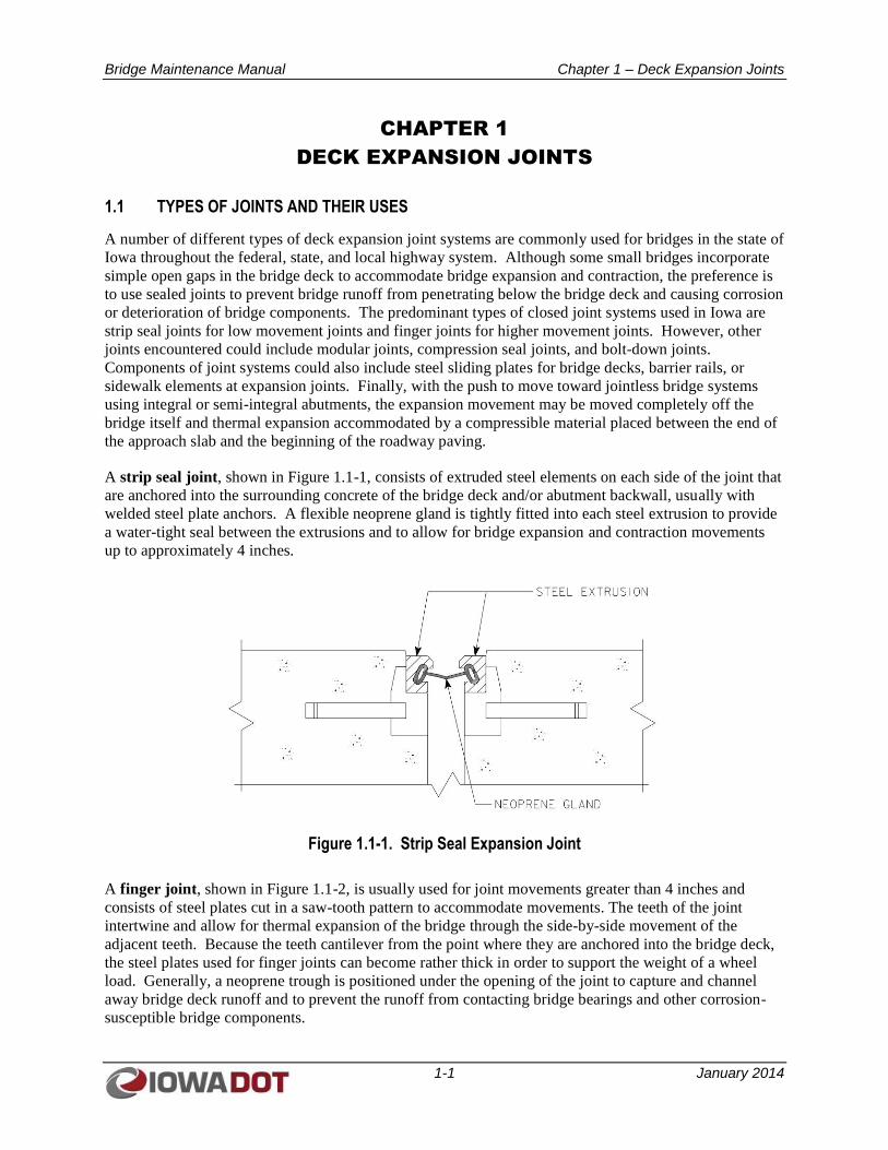
A strip seal joint, shown in Figure 1.1-1, consists of extruded steel elements on each side of the joint that
are anchored into the surrounding concrete of the bridge deck and/or abutment backwall, usually with
welded steel plate anchors. A flexible neoprene gland is tightly fitted into each steel extrusion to provide
a water-tight seal between the extrusions and to allow for bridge expansion and contraction movements
up to approximately 4 inches.
Figure 1.1-1. Strip Seal Expansion Joint
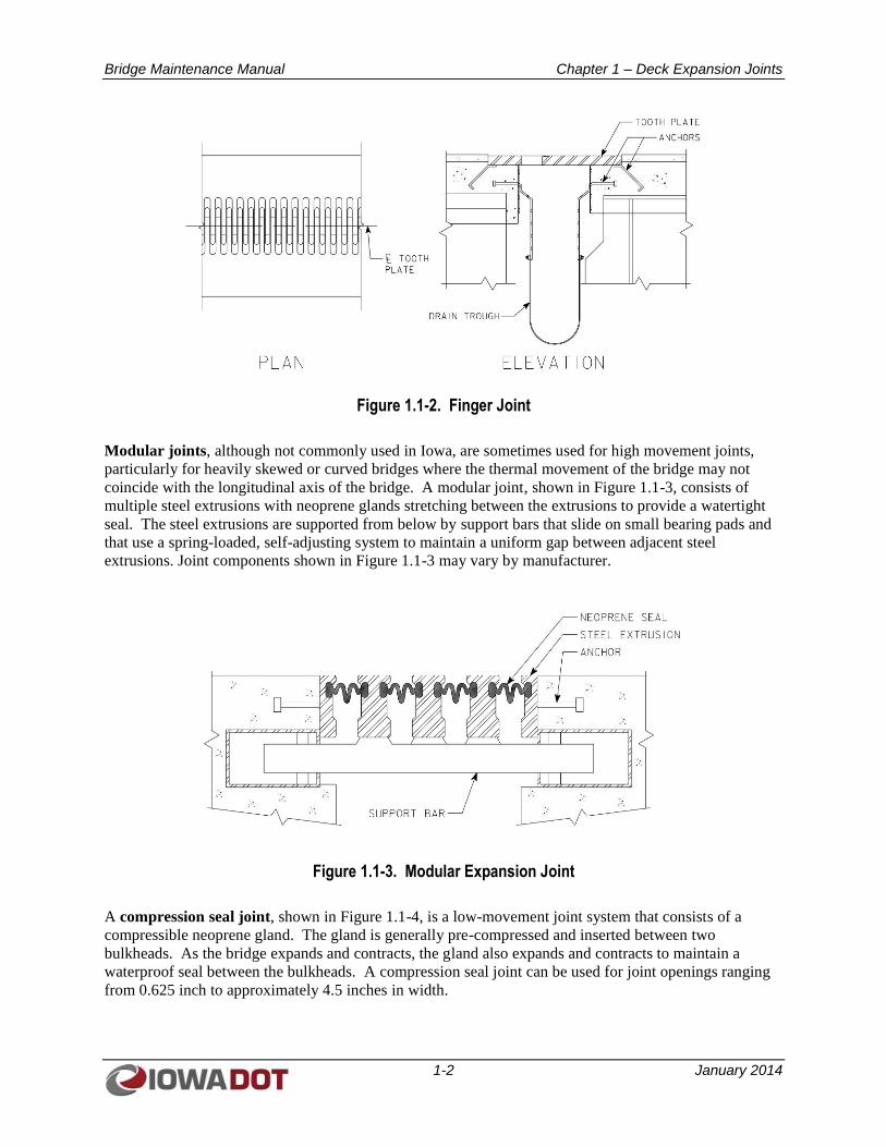
A finger joint, shown in Figure 1.1-2, is usually used for joint movements greater than 4 inches and
consists of steel plates cut in a saw-tooth pattern to accommodate movements. The teeth of the joint
intertwine and allow for thermal expansion of the bridge through the side-by-side movement of the
adjacent teeth. Because the teeth cantilever from the point where they are anchored into the bridge deck,
the steel plates used for finger joints can become rather thick in order to support the weight of a wheel
load. Generally, a neoprene trough is positioned under the opening of the joint to capture and channel
away bridge deck runoff and to prevent the runoff from contacting bridge bearings and other corrosion-
susceptible bridge components.
Bridge Maintenance Manual Chapter 1 – Deck Expansion Joints
1-2 January 2014
Figure 1.1-2. Finger Joint
Modular joints, although not commonly used in Iowa, are sometimes used for high movement joints,
particularly for heavily skewed or curved bridges where the thermal movement of the bridge may not
coincide with the longitudinal axis of the bridge. A modular joint, shown in Figure 1.1-3, consists of
multiple steel extrusions with neoprene glands stretching between the extrusions to provide a watertight
seal. The steel extrusions are supported from below by support bars that slide on small bearing pads and
that use a spring-loaded, self-adjusting system to maintain a uniform gap between adjacent steel
extrusions. Joint components shown in Figure 1.1-3 may vary by manufacturer.
Figure 1.1-3. Modular Expansion Joint
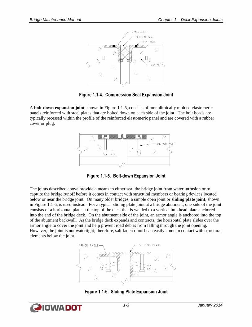
A compression seal joint, shown in Figure 1.1-4, is a low-movement joint system that consists of a
compressible neoprene gland. The gland is generally pre-compressed and inserted between two
bulkheads. As the bridge expands and contracts, the gland also expands and contracts to maintain a
waterproof seal between the bulkheads. A compression seal joint can be used for joint openings ranging
from 0.625 inch to approximately 4.5 inches in width.
Bridge Maintenance Manual Chapter 1 – Deck Expansion Joints
1-3 January 2014
Figure 1.1-4. Compression Seal Expansion Joint
A bolt-down expansion joint, shown in Figure 1.1-5, consists of monolithically molded elastomeric
panels reinforced with steel plates that are bolted down on each side of the joint. The bolt heads are
typically recessed within the profile of the reinforced elastomeric panel and are covered with a rubber
cover or plug.
Figure 1.1-5. Bolt-down Expansion Joint
The joints described above provide a means to either seal the bridge joint from water intrusion or to
capture the bridge runoff before it comes in contact with structural members or bearing devices located
below or near the bridge joint. On many older bridges, a simple open joint or sliding plate joint, shown
in Figure 1.1-6, is used instead. For a typical sliding plate joint at a bridge abutment, one side of the joint
consists of a horizontal plate at the top of the deck that is welded to a vertical bulkhead plate anchored
into the end of the bridge deck. On the abutment side of the joint, an armor angle is anchored into the top
of the abutment backwall. As the bridge deck expands and contracts, the horizontal plate slides over the
armor angle to cover the joint and help prevent road debris from falling through the joint opening.
However, the joint is not watertight; therefore, salt-laden runoff can easily come in contact with structural
elements below the joint.
Figure 1.1-6. Sliding Plate Expansion Joint

Bridge Maintenance Manual Chapter 1 – Deck Expansion Joints
1-4 January 2014
In addition to the physical joints that allow for thermal movement of the bridge deck, thermal movement
of associated bridge barriers and sidewalks must also be accommodated. For large thermal movements,
in order to prevent a vehicle from snagging on the gap created at the ends of bridge barriers, a system of
steel sliding barrier plates is often used. These sliding barrier plates are typically anchored to the barrier
on the approaching traffic side of the joint and slide over the barrier on the exiting traffic side of the joint.
Likewise, steel sliding cover plates are often used at joints on sidewalk surfaces to maintain handicap
accessibility requirements across the joint.
1.2 COMMON PROBLEMS AND CONSEQUENCES OF POOR MAINTENANCE
Bridge deck expansion joints are prone to a number of problems because, by their nature, expansion joints
incorporate moving components and because they are subjected to pounding load conditions and
environmental factors. As components of expansion joints move, they may shift out of their proper
alignment and snag on each other. In addition, a snowplow blade could snag on the misaligned
components and cause further damage. Expansion joints are also subject to the pounding load as trucks
and vehicles continually pass over them. As a result, concrete spalls adjacent to expansion joints can lead
to failure of the joint systems as the anchorages of the joints deteriorate. Joints that use a flexible gland
component are subject to sand, gravel, and road debris becoming lodged in the gland, thus leading to
puncture or tearing of the gland. Expansion joints are also subject to environmental damage, whether it is
degradation of neoprene components due to sun exposure, wear and abrasion of neoprene components, or
exposure to deicing salt. The direct result of joint failures includes the increase in corrosion and
deterioration of other bridge components resulting from failed or leaking expansion joints.
More than nearly any other bridge maintenance issue, poor joint maintenance can directly
contribute to deterioration of other critical bridge components. With the potential to allow damaging
deicing salts to contact other components, it is important to maintain waterproof joints in order to
preserve other portions of the structure. The following are some of the problems that can develop when
deck joints are not adequate or are not maintained properly:
Damaged End Diaphragms and Lateral Bracing – Steel diaphragms and lateral bracing
members directly under leaking expansion joints are subject to paint failure, accelerated
corrosion, and loss of section. Pack rust to the top flanges of the diaphragm can also cause an
upward pressure on the bottom of the deck and cause transverse deck cracking. Concrete
diaphragms are subject to chloride ion intrusion, resulting in corrosion of reinforcing steel and
subsequent spalling of concrete as the corroded reinforcing bars enlarge in volume and burst the
concrete cover.
Damaged Beam Ends – Ends of steel beams below leaking expansion joints are subject to the
same deterioration as steel end diaphragms. This deterioration is critical because the ends of
beams at the support points carry the highest shear stresses for any point along the span. The
nooks and crannies surrounding the bearing stiffeners are particularly susceptible to trapping
moisture and debris. Ends of prestressed concrete beams are also subject to deterioration in the
critical end anchorage zones of prestressing strands.
Damaged Bearings – With sediment and moisture trapped around beam bearings, steel bearings
are prone to accelerated deterioration and corrosion. Often steel bearings that were designed to
accommodate the superstructure movement will lock up due to corrosion. Because of this, the
bridge is subjected to stresses not accounted for in the original design.
Damaged Beam Seats and Caps – Chloride-laden runoff from the bridge also attacks the
reinforcing steel in the beam seats. Unchecked, spalling and cracking at the beam seats can
ultimately result in loss of support adjacent to beam bearings.
Bridge Maintenance Manual Chapter 1 – Deck Expansion Joints
1-5 January 2014
Damage from Erosion – Excessive bridge runoff passing through leaking expansion joints can
cause erosion damage along the bridge berms and can undermine the abutment foundation or
expose the piles.
Each type of expansion joint has typical problems associated with it. For strip seals, breakdown of the
neoprene gland can occur as the result of non-compressible material being lodged in the joint when the
opening is expanded. As the joint closes, these materials become wedged in the gland and can cause a
rupture with loss of water tightness of the joint. Breakdown of the gland can also occur as the result of
traffic movement over debris-filled joints. Damage to the steel extrusions or their anchorages can occur
from a snowplow blade impact or from repeated wheel impacts from traffic.
Finger joints, which by their nature are fairly robust, are also subject to snowplow blade or wheel impact
and deterioration at embedded anchors. In addition, in time, the neoprene troughs under a finger joint
may fail, leading to a leaking joint.
Modular joints, which incorporate more moving parts than simpler finger joints, have potential for a
wider range of component failures. Also, for many years, the welds connecting the steel extrusions to
their supporting steel bars were not designed to accommodate the fatigue loading to which these members
are subjected. Beginning in the mid-1990s and later mandated in the 2002 AASHTO bridge design
codes, support bar spacing was decreased and full penetration welds to the steel extrusions were required
to address this concern. As with strip seals, the neoprene glands are subject to puncture or tearing, and
any misalignment of the steel extrusions could subject the joint to snowplow damage or deterioration to
the joint anchorages and surrounding concrete.
For compression seals, it is critical that the neoprene glad is properly sized for the joint opening. If the
opening is too large, the seal will separate from the deck in cold weather and could fall out. If the
opening is too small, the seal will be damaged by the compressive forces in hot weather. Additionally, if
the opening is too small or if the seal is placed too close to the surface, it will be damaged by traffic in hot
weather as it bulges due to compression.
Bolt-down-type joints have performed poorly over the years. Due to the repeated pounding from passing
trucks or snowplows, it is not unusual for the anchor bolts to fail and entire sections of the elastomeric
panels to come loose. Also, like other gland-type joints, punctures or tears are common problems.
Components of sliding plate joints are also subject to damage from snowplows. In addition, being steel
components exposed to constant de-icing salts, pack rust can form and cause members to separate or
protrude into traffic. This is also a concern for sidewalk cover plates.
1.3 JOINT MAINTENANCE AND REPAIR PROCEDURES
1.3.1 Clean Strip Seals and Gland-type Joints
General Considerations: Cleaning of strip seal and gland-type joints should coincide with deck cleaning
activities at the end of winter operations. Work is most efficiently completed during cool but not freezing
weather, when bridge elements are in a thermally contracted condition and joints are in an open
configuration.
Procedures:
1. Establish traffic control operations on the bridge to ensure worker safety during maintenance
activities. If joints are located over active traffic, provide traffic control for the roadway below.
Bridge Maintenance Manual Chapter 1 – Deck Expansion Joints
1-6 January 2014
2. Perform deck cleaning operations; remove large debris by hand or with a loader.
3. Clean joint glands by using high pressure water or oil-free compressed air. Sweeping and
brushing may be used in conjunction with the high pressure water or compressed air. Care must
be taken to avoid puncturing the gland with the high pressure water or compressed air.
4. Collect all debris with a shovel and loader bucket. To prevent clogging, do not dispose of sand,
gravel, or road debris into joints or bridge scuppers.
5. If pressure washing is used for deck cleaning, during pressure washing operations, provide an
observer below the joint to determine if the joint is leaking. If the joint shows signs of leakage,
check the joint for punctures or tears and, if necessary, schedule follow-on maintenance to replace
the joint gland (see Section 1.3.4).
1.3.2 Cut Out Portions of Loose Steel Sliding Plate Expansion Joints
General Considerations: The primary purpose of this repair is to trim or remove only those damaged
sections that could snag on a snowplow or cause damage to vehicles. Sliding plate expansion joints
usually consist of a fixed segment attached to an embedded angle with tap screws or by welds, or attached
to a header plate by welds; the sliding plate typically slides over another embedded angle on the other side
of the joint. Even if loose or damaged portions of the sliding plate need to be removed, there is a benefit
to maintaining the portion of the sliding plate near the bridge gutter lines adjacent to barrier rails to allow
road debris to flow over the sliding plate rather than through an open joint.
Procedures:
1. Establish traffic control operations on the bridge to ensure worker safety during maintenance
activities. If joints are located over active traffic, provide traffic control for the roadway below.
2. Remove sections of slider plate assemblies with deteriorated anchorages or loose sections of
sliding plate by cutting to length with a torch; remove tap screws or cut welds to remove the loose
section of the sliding plate. Limit removal to only those sections that are damaged.
3. Clean and remove pack rust and grind smooth any remaining weld slag or sharp edges on the
embedded plate.
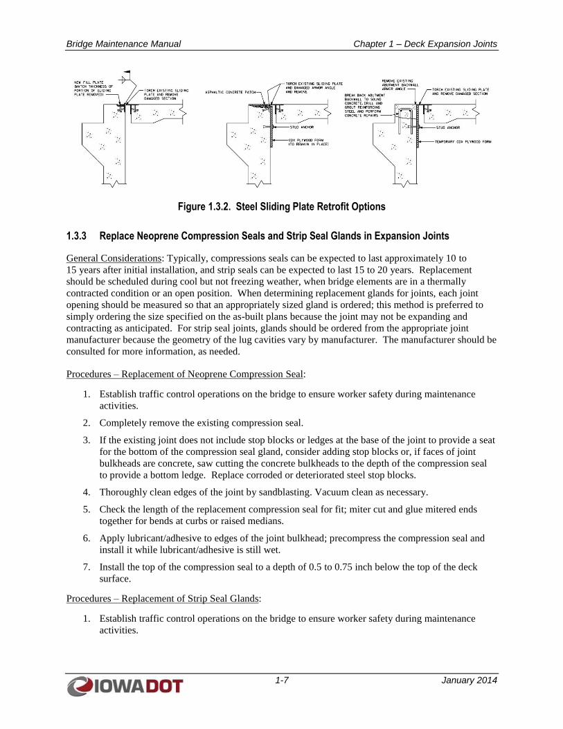
4. Temporarily retrofit joint using the options shown in Figure 1.3.2 until the joint is replaced.
5. If the open joint is a low-movement joint (that is, a relatively short bridge with only minor
thermal range of expansion) and if the bulkheads and/or steel armoring on each side of the joint
are in good condition, consider sealing the joint using a properly sized foam backer rod and Dow-
Corning 902RCS ultra-low modulus, 100% silicone rubber joint sealant, or equal. Clean contact
surfaces thoroughly prior to application of silicone sealant to ensure optimum bond.
Bridge Maintenance Manual Chapter 1 – Deck Expansion Joints
1-7 January 2014
Figure 1.3.2. Steel Sliding Plate Retrofit Options
1.3.3 Replace Neoprene Compression Seals and Strip Seal Glands in Expansion Joints
General Considerations: Typically, compressions seals can be expected to last approximately 10 to
15 years after initial installation, and strip seals can be expected to last 15 to 20 years. Replacement
should be scheduled during cool but not freezing weather, when bridge elements are in a thermally
contracted condition or an open position. When determining replacement glands for joints, each joint
opening should be measured so that an appropriately sized gland is ordered; this method is preferred to
simply ordering the size specified on the as-built plans because the joint may not be expanding and
contracting as anticipated. For strip seal joints, glands should be ordered from the appropriate joint
manufacturer because the geometry of the lug cavities vary by manufacturer. The manufacturer should be
consulted for more information, as needed.
Procedures – Replacement of Neoprene Compression Seal:
1. Establish traffic control operations on the bridge to ensure worker safety during maintenance
activities.
2. Completely remove the existing compression seal.
3. If the existing joint does not include stop blocks or ledges at the base of the joint to provide a seat
for the bottom of the compression seal gland, consider adding stop blocks or, if faces of joint
bulkheads are concrete, saw cutting the concrete bulkheads to the depth of the compression seal
to provide a bottom ledge. Replace corroded or deteriorated steel stop blocks.
4. Thoroughly clean edges of the joint by sandblasting. Vacuum clean as necessary.
5. Check the length of the replacement compression seal for fit; miter cut and glue mitered ends
together for bends at curbs or raised medians.
6. Apply lubricant/adhesive to edges of the joint bulkhead; precompress the compression seal and
install it while lubricant/adhesive is still wet.
7. Install the top of the compression seal to a depth of 0.5 to 0.75 inch below the top of the deck
surface.
Procedures – Replacement of Strip Seal Glands:
1. Establish traffic control operations on the bridge to ensure worker safety during maintenance
activities.
Bridge Maintenance Manual Chapter 1 – Deck Expansion Joints
1-8 January 2014
2. Completely remove the existing strip seal gland. This is accomplished most easily by splitting
the existing strip seal gland down the middle, initiating the removal at the curb, and upon
removing the first few feet, tying a strap to the loosened section and pulling the gland away while
maintaining an angle low to the surface of the deck.
3. Thoroughly clean the edges of the steel lug cavity using a 2-inch wire brush on a rotary grinder.
Sandblast as needed using medium grit sand. Remove all old glue and gland material along the
entire length.
4. Obtain a replacement gland from the original manufacturer of the strip seal. Check the
replacement gland for proper length, including upturns at curbs or raised medians. The
replacement gland shall be one piece from end to end of the steel extrusion and shall be installed
with the V-groove fold of the gland pointing down.
5. Apply lubricant/adhesive to the replacement gland or to the lug cavity of steel extrusions. Do not
over-apply lubricant/adhesive; less is better.
6. Fold the gland and, starting at the curb detail, push the gland into the opening, letting the lower
lug fold out into the extrusion opening. Using the manufacturer’s installation tool, have one
worker, with a tool in each hand, roll the top of the gland’s lugs into the lug cavities. After the lug
is snapped in, have a second worker use a pry bar to wedge the lower part of the gland’s lug into
the lug cavity using the opposite steel extrusion rail as a fulcrum; this relaxes the lower lug and
allows the gland to settle into the extrusion. Working from one side of the joint to the other in
approximately 4 foot sections, install the new gland across the deck from curb to curb while
lubricant/adhesive is still wet.
1.3.4 Replace CF Joint Material with Crumb Rubber Joint Material
General Considerations: Over time, joint filler for CF joints may deteriorate or begin to work its way out
of the joint. Many of these joints were previously filled with foam board material and liquid sealant.
Current policy is to replace the joint material with crumb rubber and top it with joint sealant material.
The intent of the resulting joint is to provide a compressible but not necessarily watertight joint.
Reference road design standard PV-101.
Procedures:
1. Remove old joint material. If old joint material consists of sections of foam board, usually the
material can be easily removed by hooking onto it with a tine attached to a skid loader bucket and
pulling the material free.
2. Clean out the joint and blow it free of debris with compressed air.
3. Coating of the sides and bottom of the joint with CRS2 oil emulsion or approved equal is
optional, if it is felt this helps hold the crumb rubber in place.
4. Fill the joint with crumb rubber in one or two lifts, topping each layer with CRS2 or approved
equal. Avoid compressing the crumb rubber during installation. The top of the crumb rubber and
CRS2 or approved equal should be kept ¾ inch below the driving surface to prevent tracking of
the material onto the deck.
5. If the topping is not kept ¾ inch below the driving surface, place a final layer of crumb rubber
over the top to minimize the oil emulsion from tracking onto the roadway surface.
This joint is not intended to be water tight. It is intended to allow the proper expansion and
contraction of the pavement and bridge by keeping uncompressible material out of the joint.
Bridge Maintenance Manual Chapter 1 – Deck Expansion Joints
1-9 January 2014
1.3.5 Repair Components of Modular Expansion Joints
General Considerations: Due to the variation in components from one manufacturer to another and the
restricted accessibility of modular joint components due to their enclosure within support boxes, the
original manufacturer should first be consulted prior to any attempts to repair or replace components of
modular joints. Replacement parts should be obtained from the original manufacturer. The manufacturer
should be consulted regarding repair of welds between steel extrusion rails and their support bars as welds
are a function of the spacing of the support bars.
Procedures:
1. Obtain replacement parts from the original manufacturer and consult with the manufacturer
regarding replacement procedures.
2. For replacing neoprene glands of modular joints, follow procedures similar to those described for
replacement of strip seal glands in Section 1.3.3 of this manual. Modular joints incorporate
positioning springs to maintain consistent gaps between adjacent steel rail extrusions; follow the
manufacturer’s procedures when varying the gap between rails for gland replacement.
3. If repairs include any repainting, mask any elements that are not to be painted, such as Teflon
slide surfaces of support bar bearings.
Bridge Maintenance Manual Chapter 2 – Bridge Decks and Overlays
2-1 January 2014
CHAPTER 2
BRIDGE DECKS AND OVERLAYS
2.1 TYPES OF BRIDGE DECKS AND OVERLAYS
2.1.1 Concrete Bridge Decks
Concrete bridge decks in Iowa generally consist of one of the following systems:
A full depth cast-in-place concrete bridge deck, usually 7 to 8 inches thick
A two-course cast-in-place concrete bridge deck in which the lower course is a full depth
structural slab, usually 7 to 8 inches thick, and the upper concrete wearing course is installed
upon initial construction, usually 2 inches thick
An original 7- to 8-inch-thick full depth cast-in-place concrete deck with a concrete overlay
applied a number of years after the original deck construction.
Precast concrete subpanels used as a stay-in-place form for a cast-in-place concrete topping with
full depth cast-in-place concrete deck cantilevers
A series of full depth, full bridge-width precast concrete panels that are post-tensioned together
and topped with a concrete overlay
2.1.2 Steel Bridge Decks
Steel bridge decks used in Iowa are generally open grid steel deck systems, although steel grid decks with
a concrete topping may also be found. Steel grid decks are typically used where a weight savings is
desired to increase the overall load carrying capacity of the bridge.
2.1.3 Timber Bridge Decks
Timber deck systems are generally limited to local road system bridges. Timber decks generally consist
of one of the following systems:
Transverse timber planks spanning the width of the bridge between stringer lines.
Transverse timber planks topped with longitudinally placed running boards in the wheel lines.
A “Hollywood” timber deck consisting of a layer of transverse timber planks and a full width
layer of longitudinally placed timber planks.
A nail laminated timber deck where the timber planking is oriented on edge transversely across
the deck width and planks are nailed to the adjacent planks. Nail laminated timber decks are
typically used to span greater distances between longitudinal stringers or beams.
2.2 COMMON PROBLEMS AND CONSEQUENCES OF POOR MAINTENANCE
Being subjected to deicing salts and constant loading variation from the wheel loads of passing vehicles,
bridge decks are subject to a number of environmental factors as well as variable loading conditions.
Concrete bridge decks are subject to spalling, cracking, and potholes as salt-laden water penetrates
through microcracks and pores in the concrete. The trapped moisture expands during freeze-thaw cycles,
and the chloride ions attack the reinforcing steel in the concrete deck. Both of these actions work to
expand the microcracking and lead to larger cracks, spalls, and potholes. Problems are most prominent
where moistures ponds and accumulates adjacent to barrier rails, on the underside drip line of the bridge
Bridge Maintenance Manual Chapter 2 – Bridge Decks and Overlays
2-2 January 2014
deck, and at natural depressions such as at bridge scuppers. Cyclic loading from wheel impact also
attacks the edges of embedded angles of joints, causing stress-induced concrete cracking and deterioration
at these joints. As concrete deck deterioration progresses and the deck weakens, map cracking and signs
of leaching on the underside of the deck may become more prominent.
Steel grid decks are more flexible than concrete bridge decks, and deflection of these steel grid decks
under load can lead to weld cracks where the deck is welded to steel stringers. If steel decks are
mechanically fastened to their stringer supports, the fasteners can become loose over time as the steel grid
panels distort and deflect. In addition, steel decks are subject to the same corrosive effects of salt-laden
moisture from the deck.
Being a natural material, timber decks are subject to rot from varying moisture cycles as well as wear
from the constant abrasion of wheel loads. As the moisture content of timber naturally decreases over
time, the timber planks are more susceptible to checks, splitting, and cracking. In addition, being the
most flexible of the three decking materials, timber decks are also subject to fasteners working loose,
causing movement and distortion of the deck surface.
2.3 DECK MAINTENANCE AND REPAIR PROCEDURES
2.3.1 Clean and Wash Decks
General Considerations: For maximum effectiveness, deck cleaning activities should typically be
performed shortly following the end of winter operations.
Procedures – Concrete Bridge Decks and Steel Grid Decks with Concrete Topping:
1. Establish traffic control operations on the bridge to ensure worker safety during maintenance
activities. If road debris can fall on active traffic below the bridge, provide traffic control to the
roadway below.
2. Remove large debris by hand or with a loader.
3. Clean the deck surface by mechanical sweeping, vacuum truck, or high pressure wash.
4. Collect all debris with a shovel and loader bucket; to prevent clogging, do not dispose of sand,
gravel, or road debris into joints or bridge scuppers.
Procedures – Timber Decks:
1. For timber decks with gravel overlays, periodically clean the deck of excess gravel with a road
grader to prevent excess buildup of gravel that can trap moisture and overload structural
members.
2.3.2 Remove Delaminated Concrete from Bottoms of Bridge Decks
General Considerations: Delaminated concrete on the bottoms of bridge decks in areas over active
vehicular traffic, active pedestrian traffic, navigable waterways, and railroads should be removed to
prevent personal injury or property damage.
Procedures:
1. Provide traffic control in the work area below the bridge to prevent personal injury or property
damage during concrete removal operations.
2. Remove large sections of delaminated concrete using a maximum 15-pound jack hammer.
Bridge Maintenance Manual Chapter 2 – Bridge Decks and Overlays
2-3 January 2014
3. Use hand tools to remove remaining loose or unsound concrete.
4. If falling concrete is a ongoing issue, install catch nets or, if working between interior beam lines,
install temporary wood platforms between the bottom flanges of beams to catch loose concrete.
2.3.3 Seal Deck Cracks
General Considerations: Specific cracks in bridge decks may warrant sealing. The purpose of this type of
crack sealing is to resist moisture penetration of the concrete element.
Procedures:
1. Establish traffic control operations on the bridge to ensure worker safety during maintenance
activities.
2. Remove contaminants by high pressure water, oil-free compressed air, or vacuum. When using
water to clean a crack, blow out the crack with oil-free compressed air and allow the area to dry
naturally before applying a sealer.
3. Follow the sealer supplier’s recommendations for application and curing.
2.3.4 Epoxy Inject Deck Overlays
General Considerations: Localized delaminations between the interfaces of a structural bridge deck and a
concrete overlay can be addressed by epoxy injecting the interfaces between the concrete components to
bond them together.
Procedures:
1. Establish traffic control operations on the bridge to ensure worker safety during maintenance
activities.
2. Identify locations of overlay delaminations by means of a chain drag using a sweeping motion.
Map and mark the approximate perimeter of the delaminated areas by sounding the surface of the
delaminated areas with a hammer.
3. Identify areas with an apparent higher degree of delamination (areas with the most distinctive
hollow sound) and mark these areas as injection port locations. Mark additional injection port
locations at approximately 18-inch spacing for larger voided areas and at 8-inch to 12-inch
spacing for smaller areas (less than 10 square feet).
4. Using a ½-inch vacuum concrete drill bit, hammer drill, and shop vacuum, drill each port location
to a depth where the void is penetrated. In some cases, the depth of penetration may be apparent
by a significant and immediate drop as the drill bit penetrates into the void and at other times the
depth of penetration may require the user’s judgment as the hammer drill tapping provides a more
solid sound. Do not perform drilling operations when the concrete is wet or during rain in order
to avoid clogging the vacuum bit. After drilling, use a 1/4-inch to 3/8-inch tube attached to a
vacuum to remove the concrete fines.
5. At injection port locations, insert a tap that will accept the plastic tube from the epoxy mixing
nozzle. Drive the tap into place using a hammer and a hollow steel pin that holds the tap.
6. Prepare epoxy injection equipment, including epoxy dispenser, epoxy mixer, air compressor and
rubber hoses. Prior to beginning epoxy injection of the deck overlay, test equipment and mixing
of epoxy by taking a sample of the mixed epoxy. Within 10-15 minutes of mixing, the epoxy
sample should begin to heat up and harden.
Bridge Maintenance Manual Chapter 2 – Bridge Decks and Overlays
2-4 January 2014
7. Starting near the center of the delaminated area, place the 1/4-inch tubing that extends from the
mixer over an injection port. Begin injection at a pressure of approximately 30 psi. Avoid
pressures greater than 35 psi to prevent pop-outs of the deck delamination. Where the cycling
rate of the dispenser is very slow or not progressing, check the back pressure at the injection port
tap. A significant amount of back pressure would indicate a different port should be selected.
Periodically have someone check the bottom of the deck to verify that epoxy is not exiting
through a seam or fissure. If so, immediately cease pumping operations until the epoxy can set
up and seal the crack.
8. Monitor the progress of the epoxy injection by hammer sounding the delaminated area and
observing adjacent injection ports. Once it is determined a region of the delaminated area is
nearing complete injection based on the cycling rate of the dispenser, the back pressure at the
port, or both, stop epoxy flow by closing the control valve. Remove the injection hose and clamp
the port using a ferrule. Repeat injection operations as subsequent injection ports.
9. Upon completion of the injection process, immediately clean all mixing and dispensing
equipment and hoses. Remaining injection ports should be sheared off using a flat head shovel.
Mix large epoxy spills with mason sand and then shovel from the deck. Sprinkle smaller spills
with mason sand. Traffic can be allowed to travel on the deck immediately after completion of
injection.
2.3.5 Patch Bridge Decks with Asphaltic Concrete
General Procedures: Patching bridge decks with asphaltic concrete (ACC) should be considered a
temporary fix only to minimize further deck damage until weather conditions will allow permanent
repairs with concrete. ACC patches are typically installed when adverse weather conditions preclude
proper preparation of the repair area. ACC does not provide the structural capacity of concrete and
should not be used as a permanent bridge deck patch material, nor should it be used for full depth deck
patches.
Procedures:
1. Establish traffic control operations on the bridge to ensure worker safety during maintenance
activities.
2. Broom pothole to remove loose material, and clean with oil-free compressed air.
3. Shovel cold patch ACC into the pothole, slightly overfilling the hole.
4. Allow active traffic to run over patch material to compress it into the pothole and flatten it.
2.3.6 Patch Bridge Decks with Concrete
General Considerations: Potholes and large spalls on the surface of the bridge deck should be
permanently patched with concrete as weather conditions permit. Unattended potholes and spalls will
trap additional moisture leading to further freeze-thaw damage and corrosion of reinforcing steel.
Procedures:
1. Establish traffic control operations on the bridge to ensure worker safety during maintenance
activities. If the patch could extend full depth, provide traffic control for the roadway below.
2. Using a 2-inch-wide chisel-point jackhammer, remove unsound concrete and/or ACC patch
material from the damaged area of the deck, extending the limits of the damaged area until sound
concrete is encountered. Depth of removal shall be a minimum of 2 inches or to the minimum
Bridge Maintenance Manual Chapter 2 – Bridge Decks and Overlays
2-5 January 2014
depth recommended by the manufacturer of the concrete patch material. If unsound concrete
extends below the top mat of reinforcing steel, remove unsound concrete to at least 0.75 inches
below the top reinforcing steel.
3. Provide a 0.75-inch-deep vertical saw cut around the perimeter of the damaged area to square up
the repair area and eliminate feathered edges. Jackhammer as needed to extend removals to the
saw cut lines.
4. Clean corroded reinforcing steel. If needed, replace damaged reinforcing steel with new bars, and
securely tie new reinforcing steel into place. Touch up exposed surfaces of epoxy coated
reinforcing steel with an approved coating material.
5. Clean the repair area by sandblasting. Protect epoxy coated reinforcing from the cleaning
process. Clean epoxy coated reinforcing with hand tools that will not damage the epoxy coating.
Follow with an air blast of oil-free compressed air. Repair area may be damp, but there should be
no standing water.
6. Fill the damaged area with a high-early strength concrete patch material from the approved
products list. Maintain traffic control around the patched area until the concrete has cured in
accordance with the manufacturer’s recommendations.
2.3.7 Weld Loose Steel Decking to Steel Stringer Beams
General Considerations: The tight spacing of bearing bars for open grid steel decks makes access for
welding difficult.
Procedures:
1. Establish traffic control operations on the bridge to ensure worker safety during maintenance
activities.
2. Grind smooth remnants of previous welds and existing weld slag if access is available for
grinding.
3. Weld loose steel decking to steel stringer beams using a certified welder and pre-approved
welding procedures in accordance with the ANSI/AWS D1.1 Structural Welding Code.
2.3.8 Replace Timber Deck Planks
General Considerations: For timber bridge decks consisting of transverse and longitudinal courses of
timber planking, replacement of damaged timber planks for the lower course of planks will first require
removal of the upper course planks in conflict.
Procedures:
1. Establish traffic control operations on the bridge to ensure worker safety during maintenance
activities.
2. For timber decks with a gravel overlay, remove the gravel overlay with a road grader or locally
remove gravel at the damaged timber plank by sweeping.
3. Remove the damaged timber plank and all associated fasteners.
4. Trial fit a new plank and cut it to length. Provide a 0.25-inch gap between adjacent deck planks
to allow for drainage, expansion, and air circulation.
5. Fasten the new plank to existing stringers.
Bridge Maintenance Manual Chapter 3 – Bridge Drainage Systems
3-1 January 2014
CHAPTER 3
BRIDGE DRAINAGE SYSTEMS
3.1 TYPES OF BRIDGE DRAINAGE SYSTEMS
Bridge drainage systems consist of multiple components to remove rainwater and snowmelt runoff from
the surface of the bridge deck. For short bridges where the quantity of runoff at the gutters remains small,
no specific bridge drainage system may be needed. Runoff would simply flow over the joints at the ends
of the bridge and would be captured either in storm drains along the roadway approaches or dispersed
onto the shoulder areas of the approach roadway.
For longer bridges where the quantity of runoff could encroach into the driving lanes of the bridge, deck
drains or scuppers would be placed strategically along the length of the bridge to intercept runoff at the
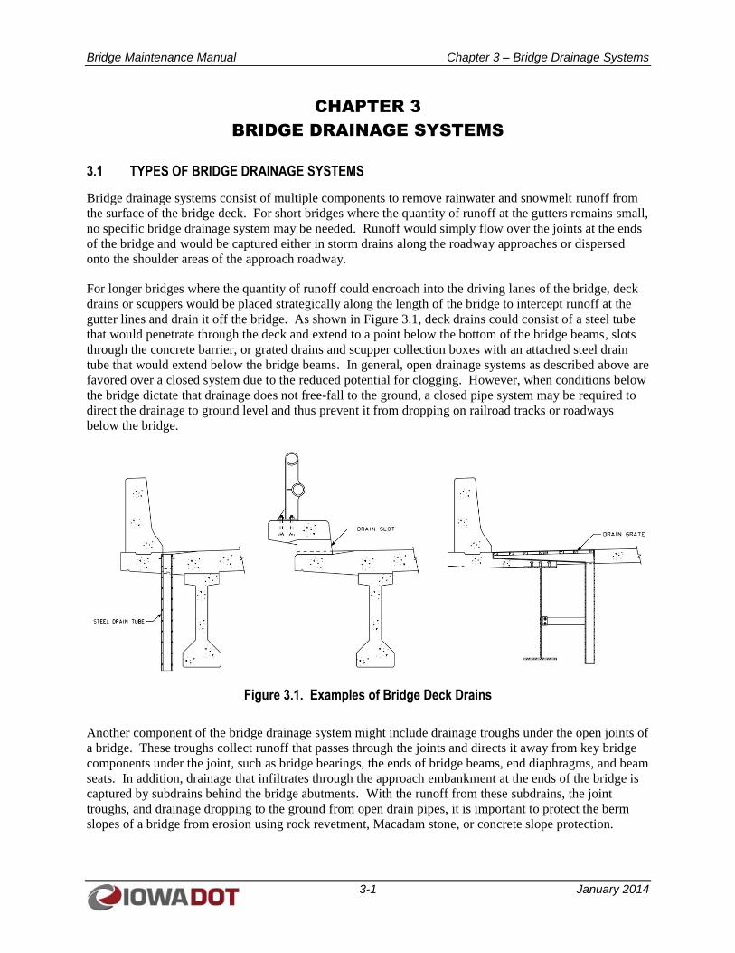
gutter lines and drain it off the bridge. As shown in Figure 3.1, deck drains could consist of a steel tube
that would penetrate through the deck and extend to a point below the bottom of the bridge beams, slots
through the concrete barrier, or grated drains and scupper collection boxes with an attached steel drain
tube that would extend below the bridge beams. In general, open drainage systems as described above are
favored over a closed system due to the reduced potential for clogging. However, when conditions below
the bridge dictate that drainage does not free-fall to the ground, a closed pipe system may be required to
direct the drainage to ground level and thus prevent it from dropping on railroad tracks or roadways
below the bridge.
Figure 3.1. Examples of Bridge Deck Drains
Another component of the bridge drainage system might include drainage troughs under the open joints of
a bridge. These troughs collect runoff that passes through the joints and directs it away from key bridge
components under the joint, such as bridge bearings, the ends of bridge beams, end diaphragms, and beam
seats. In addition, drainage that infiltrates through the approach embankment at the ends of the bridge is
captured by subdrains behind the bridge abutments. With the runoff from these subdrains, the joint
troughs, and drainage dropping to the ground from open drain pipes, it is important to protect the berm
slopes of a bridge from erosion using rock revetment, Macadam stone, or concrete slope protection.
Bridge Maintenance Manual Chapter 3 – Bridge Drainage Systems
3-2 January 2014
3.2 COMMON PROBLEMS AND CONSEQUENCES OF POOR MAINTENANCE
A common problem resulting from poor maintenance of bridge drainage systems is clogging of the drains.
This can result in runoff encroaching into the driving lane and freezing or ponding. Failure of bridge
drainage systems also causes runoff to be directed where it is not intended. As a result, bridge
components could be exposed to corrosive deicing salts, thus leading to premature deterioration of those
components. Also, if one drain is clogged, it could cause an adjacent drain to be overloaded, again
causing runoff to be directed where it is not intended.
Clogging and deterioration of the bridge drainage system can be caused by corrosion, excessive build up
of sand and gravel from winter operations, build up of animal nesting material, and road debris (for
example, soda cans or bottles).
3.3 BRIDGE DRAINAGE SYSTEM MAINTENANCE AND REPAIR PROCEDURES
3.3.1 Unplug Deck Drains
General Considerations: Efforts to unplug deck drains should be scheduled annually at a minimum and
should generally coincide with joint and deck cleaning activities at the end of normal winter operations.
Procedures:
1. Establish traffic control operations on the bridge to ensure worker safety during maintenance
activities.
2. For bridge drains and scuppers with attached grates, remove the grate to provide access to the
drain tube. Remove the drain tube clean-out plugs (if present).
3. Remove visual obstructions by hand or with appropriate hand tools. Clean out scupper boxes
with a shovel. Do not dispose of debris in bridge drains or joints.
4. For inaccessible drain clogs, use high pressure water, compressed air, or a drain snake to clear
obstructions.
5. Following removal of obstructions, flush the drain with water to ensure unimpeded flow.
6. Replace drain grates and clean-out plugs; thoroughly tighten attachment bolts or screws.
7. Clean sediment and/or debris from auxiliary bridge components, bridge bearings, and beam seats.
3.3.2 Repair Deck Drains and/or Add Extensions
General Considerations: Downspouts for deck drains, particularly drain pipes that incorporate bends in
the downspout piping that are more prone to clogging, may rust out over time and require repair. In
addition, if downspout piping does not currently extend below the bottom of the beam, deck runoff could
be falling on the lower flange of the beam and causing deterioration of the beam. Finally, downspout
piping may be concentrating runoff onto the berm slope in front of the abutment and causing erosion, thus
requiring the runoff to be redirected.
Procedures – Damaged Deck Drain Downspout:
1. Remove the damaged portion of the deck drain downspout pipe by cutting it with a torch.
2. Grind the free ends of the downspout pipe to a planar section and remove all burs.
Bridge Maintenance Manual Chapter 3 – Bridge Drainage Systems
3-3 January 2014
3. Couple in place a new section of steel drain pipe using flexible mechanical pipe couplers at each
end (Dressler coupling or equal).
4. Alternatively, using double-walled corrugated polyvinyl chloride (PVC) pipe (which has a
smooth wall on the inside), connect the remaining extensions of steel pipe to corrugated PVC
pipe using pipe clamp bands.
Procedures – Drain Extension Addition:
1. Remove the existing steel drain pipe to within 6 to 8 inches of the bottom of the bridge deck.
2. Fit an oversized smooth-walled PVC pipe over the existing steel pipe extension, and attach the
PVC pipe to the bottom of the bridge deck with L-brackets and stud anchors.
3. Alternatively, extend the drain pipe by attaching a section of double-walled corrugated PVC pipe
(which has a smooth wall on the inside) of comparable diameter to the existing downspout pipe
using pipe clamp bands.
3.3.3 Clean and Repair Expansion Joint Drainage Troughs
General Considerations: Efforts to clean and repair expansion joint drainage troughs should be scheduled
to coincide with joint and deck cleaning activities at the end of normal winter operations.
Procedures:
1. If cleaning operations are staged from the top of the bridge deck, establish traffic control
operations on the bridge to ensure worker safety during maintenance activities. If drainage
troughs are located over active traffic, provide traffic control for the roadway below.
2. Flush expansion joint drainage troughs with a high volume of pressurized water to remove sand,
gravel, and road sediment. Working from above the joint or from the end of the trough, progress
from the high side of the trough to its low point. Maintain a water pressure that will not damage
neoprene trough material but will provide adequate volume to flush debris from the trough.
3. For torn or damaged neoprene trough drapes, remove damaged sections of drape and replace
them with new sections of neoprene drape.
4. Once the drainage trough is cleared, scoop or shovel sediment from the collection box. Snake the
drainpipe from the collection box to the outlet to ensure free flow of drainage to the outlet point.
5. Clean accumulated sediment and/or debris from auxiliary bridge components, bridge bearings,
and beam seats.
Bridge Maintenance Manual Chapter 4 – Bridge Railings
4-1 January 2014
CHAPTER 4
BRIDGE RAILINGS
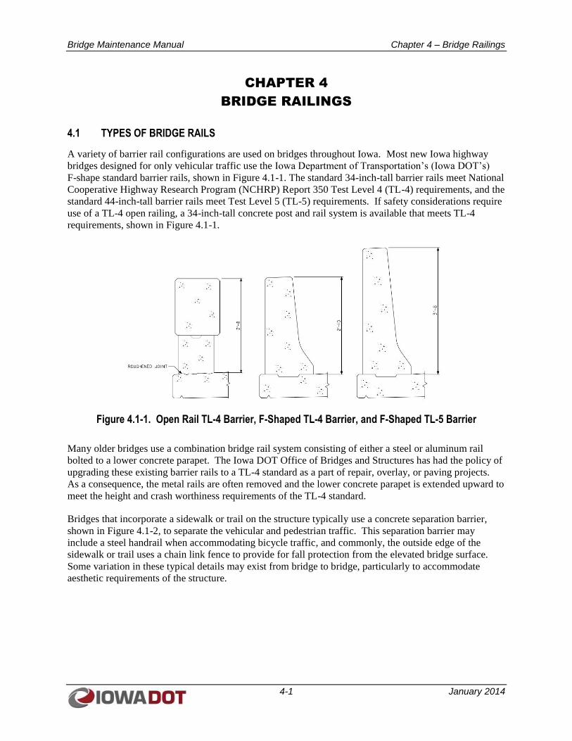
4.1 TYPES OF BRIDGE RAILS
A variety of barrier rail configurations are used on bridges throughout Iowa. Most new Iowa highway
bridges designed for only vehicular traffic use the Iowa Department of Transportation’s (Iowa DOT’s)
F-shape standard barrier rails, shown in Figure 4.1-1. The standard 34-inch-tall barrier rails meet National
Cooperative Highway Research Program (NCHRP) Report 350 Test Level 4 (TL-4) requirements, and the
standard 44-inch-tall barrier rails meet Test Level 5 (TL-5) requirements. If safety considerations require
use of a TL-4 open railing, a 34-inch-tall concrete post and rail system is available that meets TL-4
requirements, shown in Figure 4.1-1.
Figure 4.1-1. Open Rail TL-4 Barrier, F-Shaped TL-4 Barrier, and F-Shaped TL-5 Barrier
Many older bridges use a combination bridge rail system consisting of either a steel or aluminum rail
bolted to a lower concrete parapet. The Iowa DOT Office of Bridges and Structures has had the policy of
upgrading these existing barrier rails to a TL-4 standard as a part of repair, overlay, or paving projects.
As a consequence, the metal rails are often removed and the lower concrete parapet is extended upward to
meet the height and crash worthiness requirements of the TL-4 standard.
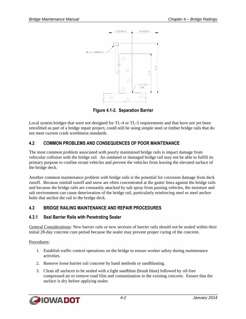
Bridges that incorporate a sidewalk or trail on the structure typically use a concrete separation barrier,
shown in Figure 4.1-2, to separate the vehicular and pedestrian traffic. This separation barrier may
include a steel handrail when accommodating bicycle traffic, and commonly, the outside edge of the
sidewalk or trail uses a chain link fence to provide for fall protection from the elevated bridge surface.
Some variation in these typical details may exist from bridge to bridge, particularly to accommodate
aesthetic requirements of the structure.
Bridge Maintenance Manual Chapter 4 – Bridge Railings
4-2 January 2014
Figure 4.1-2. Separation Barrier
Local system bridges that were not designed for TL-4 or TL-5 requirements and that have not yet been
retrofitted as part of a bridge repair project, could still be using simple steel or timber bridge rails that do
not meet current crash worthiness standards.
4.2 COMMON PROBLEMS AND CONSEQUENCES OF POOR MAINTENANCE
The most common problem associated with poorly maintained bridge rails is impact damage from
vehicular collision with the bridge rail. An outdated or damaged bridge rail may not be able to fulfill its
primary purpose to confine errant vehicles and prevent the vehicles from leaving the elevated surface of
the bridge deck.
Another common maintenance problem with bridge rails is the potential for corrosion damage from deck
runoff. Because rainfall runoff and snow are often concentrated at the gutter lines against the bridge rails
and because the bridge rails are constantly attacked by salt spray from passing vehicles, the moisture and
salt environment can cause deterioration of the bridge rail, particularly reinforcing steel or steel anchor
bolts that anchor the rail to the bridge deck.
4.3 BRIDGE RAILING MAINTENANCE AND REPAIR PROCEDURES
4.3.1 Seal Barrier Rails with Penetrating Sealer
General Considerations: New barrier rails or new sections of barrier rails should not be sealed within their
initial 28-day concrete cure period because the sealer may prevent proper curing of the concrete.
Procedures:
1. Establish traffic control operations on the bridge to ensure worker safety during maintenance
activities.
2. Remove loose barrier rail concrete by hand methods or sandblasting.
3. Clean all surfaces to be sealed with a light sandblast (brush blast) followed by oil-free
compressed air to remove road film and contamination to the existing concrete. Ensure that the
surface is dry before applying sealer.
Bridge Maintenance Manual Chapter 4 – Bridge Railings
4-3 January 2014
4. Apply sealing material meeting the requirements of the Standard Specifications, Article
4139.01.B, to the tops and traffic sides of the barrier rail as well as to a section of the roadway
surface of the bridge deck extending 1 foot into the roadway from the gutter line.
4.3.2 Patch Concrete Barrier Rails and Curbs
General Considerations: To minimize water intrusion and active deterioration of barrier rails, deteriorated
areas of barrier rails and curbs should be repaired to maintain their structural integrity.
Procedures:
1. Establish traffic control operations on the bridge to ensure worker safety during maintenance
activities.
2. Using a 2-inch-wide chisel-point jackhammer, remove unsound concrete from the damaged area
of the barrier rail, extending the limits of the damaged area until sound concrete is encountered.
3. Using a chop saw, provide a 0.75-inch-deep saw cut around the perimeter of the damaged area to
square up the repair area and eliminate feathered edges. Jackhammer as needed to extend
removals to the saw cut lines. Limit jackhammer size to a nominal 30-pound class, and limit
chipping hammer size to 15-pound class.
4. Clean or remove corroded reinforcing steel. If needed, replace damaged reinforcing steel with
new bars and securely tie new reinforcing steel into place. Touch up exposed surfaces of epoxy
coated reinforcing steel with an approved coating material.
5. Clean the repair area by sandblasting. Protect epoxy coated reinforcing from the cleaning
process. Clean epoxy coated reinforcing with hand tools that will not damage the epoxy coating.
Follow with an air blast of oil-free compressed air.
6. For shallow repairs (0.75 to 1.5 inches deep where no form work is used to support the patching
material), first apply a bonding grout conforming to the Standard Specifications, Article
2426.02.B.1; ensure that the repair area is dry before placing grout. Concrete for shallow repairs
shall conform with the Standard Specifications, Table 2426.02-1. Place concrete before the grout
dries out.
7. For regular repairs (a minimum depth of 1.5 inches or 0.75 inch behind an unbonded reinforcing
bar and where form work is used), no bonding grout is required. Use a Class O concrete mix for
the repair concrete. Ensure that the existing concrete surface is dry before placing new concrete.
8. Apply a white pigmented curing compound to the concrete immediately following concrete
finishing or immediately after removing forms. The application rate shall be 100 square feet per
gallon.
4.3.3 Repair/Replace Aluminum or Steel Bridge Rail Damaged by Vehicular Impact
General Considerations: Aluminum or steel rail that has been damaged or loosened by impact may not be
adequate to redirect an errant vehicle or prevent a vehicle from leaving the elevated bridge deck surface.
Procedures:
1. Establish traffic control operations on the bridge to ensure worker safety during maintenance
activities.
2. Cut the damaged portion of the rail or remove anchor bolt nuts to allow removal of damaged
sections of the metal rail.
Bridge Maintenance Manual Chapter 4 – Bridge Railings
4-4 January 2014
3. Where rail post anchor bolts are bent, remove the post and add a temporary nut to the bent anchor
bolts so that the anchor bolts can be straightened with a hammer without damaging the threads.
Replace broken or damaged anchor bolts by drilling out the damaged anchor bolt and grouting in
a new anchor bolt in accordance with the Standard Specifications, Article 2405.03.H.2.a.
4. Install a new section of metal rail and posts to replace damaged sections. Anchor post sections
with anchor bolts.
4.3.4 Repair Concrete Barrier Rails Damaged by Vehicular Impact
General Consideration: Sections of concrete barrier rail that have experienced total failure or extensive
cracking due to vehicular impact may require total replacement of the damaged section to reestablish
crash worthiness of barrier rail system.
Procedures:
1. Establish traffic control operations on the bridge to ensure worker safety during maintenance
activities.
2. Using a 2-inch-wide chisel bit, jackhammer and remove the damaged section of concrete barrier
rail. Remove concrete back to sound concrete. Limit jackhammer size to a nominal 30-pound
class, and limit chipping hammer size to 15-pound class.
3. Straighten and re-use existing reinforcing steel that is still intact.
4. Where vertical barrier rail reinforcing steel has been broken away at the barrier rail/deck
interface, drill and grout new anchor reinforcing steel into the bridge deck. Use a polymer grout
system in conformance with Materials I.M. 491.11. The depth of the grout hole shall be in
accordance with the grout manufacturer’s recommendations. Ensure that the depth of the hole
does not result in punching through the bottom of the deck.
5. Replace damaged longitudinal reinforcing steel that cannot be incorporated in the repaired
section. Provide adequate lap splice to the existing longitudinal reinforcing steel, or drill and
grout new reinforcing steel into the existing barrier using hydraulic cement grout conforming
with the requirements of Materials I.M. 491.13 or polymer grout conforming with Materials I.M.
491.11. Securely tie all reinforcing steel in place. Touch up damaged epoxy coating for
reinforcing steel with an approved coating material.
6. Clean the concrete interface surface of the existing concrete barrier rail by sandblasting. Follow
with an air blast of oil-free compressed air.
7. Form area of barrier rail to be replaced, and cast replacement section with Class C concrete mix.
Construction joints shall be spaced at a minimum of 20 feet on centers. Construction joint
contact surfaces shall be coated with an approved bond breaker material.
8. Apply a white pigmented curing compound to the concrete immediately following form removal.
The application rate shall be 100 square feet per gallon.
Bridge Maintenance Manual Chapter 5 – Bridge Bearings
5-1 January 2014
CHAPTER 5
BRIDGE BEARINGS
5.1 TYPES OF BEARINGS
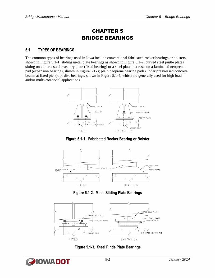
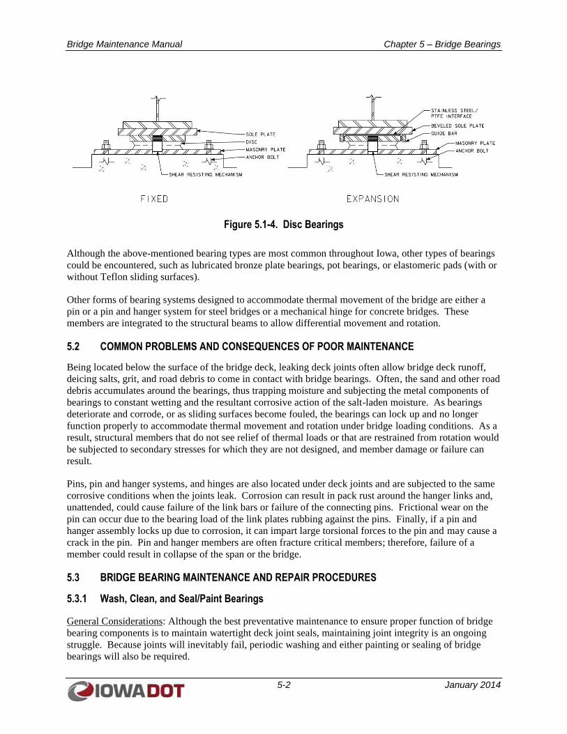
The common types of bearings used in Iowa include conventional fabricated rocker bearings or bolsters,
shown in Figure 5.1-1; sliding metal plate bearings as shown in Figure 5.1-2; curved steel pintle plates
sitting on either a steel masonry plate (fixed bearing) or a steel plate that rests on a laminated neoprene
pad (expansion bearing), shown in Figure 5.1-3; plain neoprene bearing pads (under prestressed concrete
beams at fixed piers); or disc bearings, shown in Figure 5.1-4, which are generally used for high load
and/or multi-rotational applications.
Figure 5.1-1. Fabricated Rocker Bearing or Bolster
Figure 5.1-2. Metal Sliding Plate Bearings
Figure 5.1-3. Steel Pintle Plate Bearings
Bridge Maintenance Manual Chapter 5 – Bridge Bearings
5-2 January 2014
Figure 5.1-4. Disc Bearings
Although the above-mentioned bearing types are most common throughout Iowa, other types of bearings
could be encountered, such as lubricated bronze plate bearings, pot bearings, or elastomeric pads (with or
without Teflon sliding surfaces).
Other forms of bearing systems designed to accommodate thermal movement of the bridge are either a
pin or a pin and hanger system for steel bridges or a mechanical hinge for concrete bridges. These
members are integrated to the structural beams to allow differential movement and rotation.
5.2 COMMON PROBLEMS AND CONSEQUENCES OF POOR MAINTENANCE
Being located below the surface of the bridge deck, leaking deck joints often allow bridge deck runoff,
deicing salts, grit, and road debris to come in contact with bridge bearings. Often, the sand and other road
debris accumulates around the bearings, thus trapping moisture and subjecting the metal components of
bearings to constant wetting and the resultant corrosive action of the salt-laden moisture. As bearings
deteriorate and corrode, or as sliding surfaces become fouled, the bearings can lock up and no longer
function properly to accommodate thermal movement and rotation under bridge loading conditions. As a
result, structural members that do not see relief of thermal loads or that are restrained from rotation would
be subjected to secondary stresses for which they are not designed, and member damage or failure can
result.
Pins, pin and hanger systems, and hinges are also located under deck joints and are subjected to the same
corrosive conditions when the joints leak. Corrosion can result in pack rust around the hanger links and,
unattended, could cause failure of the link bars or failure of the connecting pins. Frictional wear on the
pin can occur due to the bearing load of the link plates rubbing against the pins. Finally, if a pin and
hanger assembly locks up due to corrosion, it can impart large torsional forces to the pin and may cause a
crack in the pin. Pin and hanger members are often fracture critical members; therefore, failure of a
member could result in collapse of the span or the bridge.
5.3 BRIDGE BEARING MAINTENANCE AND REPAIR PROCEDURES
5.3.1 Wash, Clean, and Seal/Paint Bearings
General Considerations: Although the best preventative maintenance to ensure proper function of bridge
bearing components is to maintain watertight deck joint seals, maintaining joint integrity is an ongoing
struggle. Because joints will inevitably fail, periodic washing and either painting or sealing of bridge
bearings will also be required.
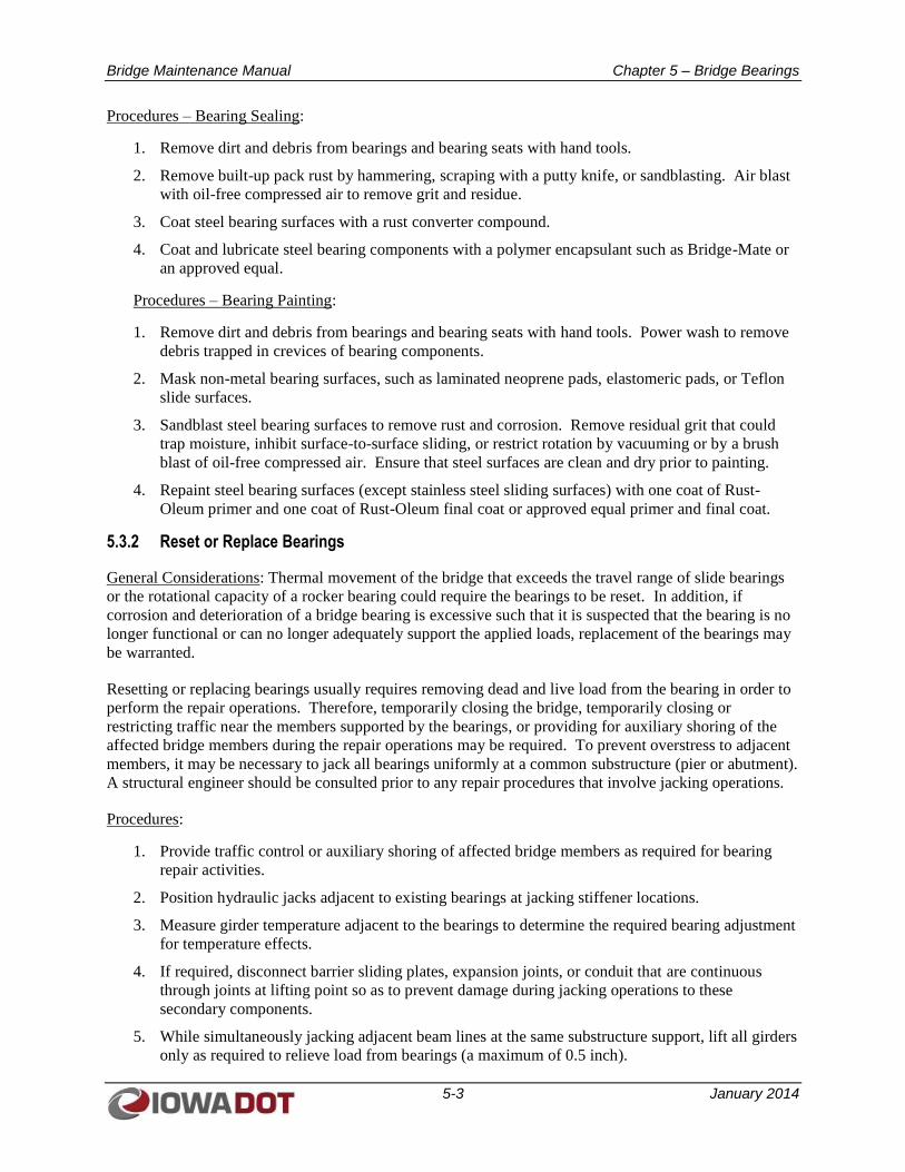
Bridge Maintenance Manual Chapter 5 – Bridge Bearings
5-3 January 2014
Procedures – Bearing Sealing:
1. Remove dirt and debris from bearings and bearing seats with hand tools.
2. Remove built-up pack rust by hammering, scraping with a putty knife, or sandblasting. Air blast
with oil-free compressed air to remove grit and residue.
3. Coat steel bearing surfaces with a rust converter compound.
4. Coat and lubricate steel bearing components with a polymer encapsulant such as Bridge-Mate or
an approved equal.
Procedures – Bearing Painting:
1. Remove dirt and debris from bearings and bearing seats with hand tools. Power wash to remove
debris trapped in crevices of bearing components.
2. Mask non-metal bearing surfaces, such as laminated neoprene pads, elastomeric pads, or Teflon
slide surfaces.
3. Sandblast steel bearing surfaces to remove rust and corrosion. Remove residual grit that could
trap moisture, inhibit surface-to-surface sliding, or restrict rotation by vacuuming or by a brush
blast of oil-free compressed air. Ensure that steel surfaces are clean and dry prior to painting.
4. Repaint steel bearing surfaces (except stainless steel sliding surfaces) with one coat of Rust-
Oleum primer and one coat of Rust-Oleum final coat or approved equal primer and final coat.
5.3.2 Reset or Replace Bearings
General Considerations: Thermal movement of the bridge that exceeds the travel range of slide bearings
or the rotational capacity of a rocker bearing could require the bearings to be reset. In addition, if
corrosion and deterioration of a bridge bearing is excessive such that it is suspected that the bearing is no
longer functional or can no longer adequately support the applied loads, replacement of the bearings may
be warranted.
Resetting or replacing bearings usually requires removing dead and live load from the bearing in order to
perform the repair operations. Therefore, temporarily closing the bridge, temporarily closing or
restricting traffic near the members supported by the bearings, or providing for auxiliary shoring of the
affected bridge members during the repair operations may be required. To prevent overstress to adjacent
members, it may be necessary to jack all bearings uniformly at a common substructure (pier or abutment).
A structural engineer should be consulted prior to any repair procedures that involve jacking operations.
Procedures:
1. Provide traffic control or auxiliary shoring of affected bridge members as required for bearing
repair activities.
2. Position hydraulic jacks adjacent to existing bearings at jacking stiffener locations.
3. Measure girder temperature adjacent to the bearings to determine the required bearing adjustment
for temperature effects.
4. If required, disconnect barrier sliding plates, expansion joints, or conduit that are continuous
through joints at lifting point so as to prevent damage during jacking operations to these
secondary components.
5. While simultaneously jacking adjacent beam lines at the same substructure support, lift all girders
only as required to relieve load from bearings (a maximum of 0.5 inch).
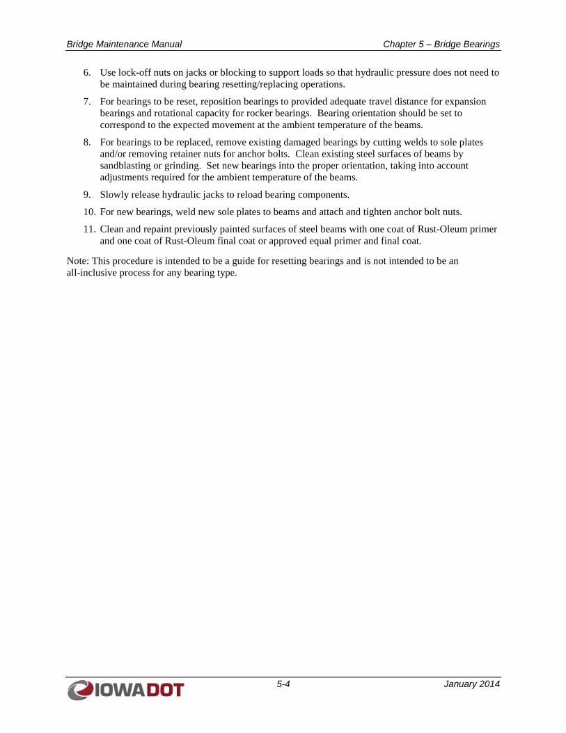
Bridge Maintenance Manual Chapter 5 – Bridge Bearings
5-4 January 2014
6. Use lock-off nuts on jacks or blocking to support loads so that hydraulic pressure does not need to
be maintained during bearing resetting/replacing operations.
7. For bearings to be reset, reposition bearings to provided adequate travel distance for expansion
bearings and rotational capacity for rocker bearings. Bearing orientation should be set to
correspond to the expected movement at the ambient temperature of the beams.
8. For bearings to be replaced, remove existing damaged bearings by cutting welds to sole plates
and/or removing retainer nuts for anchor bolts. Clean existing steel surfaces of beams by
sandblasting or grinding. Set new bearings into the proper orientation, taking into account
adjustments required for the ambient temperature of the beams.
9. Slowly release hydraulic jacks to reload bearing components.
10. For new bearings, weld new sole plates to beams and attach and tighten anchor bolt nuts.
11. Clean and repaint previously painted surfaces of steel beams with one coat of Rust-Oleum primer
and one coat of Rust-Oleum final coat or approved equal primer and final coat.
Note: This procedure is intended to be a guide for resetting bearings and is not intended to be an
all-inclusive process for any bearing type.
Bridge Maintenance Manual Chapter 6 – Bridge Superstructures
6-1 January 2014
CHAPTER 6
BRIDGE SUPERSTRUCTURES
6.1 COMMON PROBLEMS AND CONSEQUENCES OF POOR MAINTENANCE
Bridge superstructures are subject to damage or deterioration from a number of sources. These sources of
damage and deterioration may include impact damage from vehicle collision or stream debris,
environmental damage (for example, concrete deterioration, corrosion, rot, fire damage, or thermal
stress), load-induced damage from overload conditions, or a combination of these factors.
As primary load-carrying members of a bridge, poorly maintained and inadequately repaired bridge
superstructures result in, at least, a reduced service life for the bridge and, at worst, possible failure or
collapse of the bridge. Additionally, deferring maintenance on bridge superstructures often leads to the
need for more severe repairs later, which are generally more costly and translate into longer, more
involved repair delays to the traveling public.
6.1.1 Reinforced Concrete and Prestressed Concrete Beams
A common type of damage to reinforced concrete or pretressed concrete beam superstructures is impact
damage from vehicle collision. Prestressed concrete beam bridges are frequently used for highway and
railroad overpass structures, and impact damage from overheight vehicles is a common occurrence. As a
result, repair procedures are outlined in Section 6.2, below, for dealing with concrete spalls and cracks
resulting from vehicle strikes.
Another common source of damage for reinforced concrete beam and prestressed concrete beam bridges
is damage to the ends of beams from leaking bridge joints. As salt-laden bridge runoff is deposited on the
ends of these beams, the concrete is subjected to moisture penetration and constant freeze-thaw
deterioration. As the moisture penetrates through the concrete cover, steel reinforcing bars and
pretressing strands begin to corrode. As they corrode, steel reinforcing bars and pretressing strands
increase in volume and cause bursting of the concrete cover, thus accelerating the rate of deterioration of
these types of beams.
6.1.2 Steel Girder or Rolled Steel Beam
Like concrete beams, steel beams are also subject to impact damage. Although somewhat more robust to
impact damage, bent and damaged steel members are subject to stress concentrations that could adversely
affect the performance of the steel beam.
Another form of deterioration for steel beams is fatigue cracking from the cyclic application of live loads.
Fatigue cracking occurs in zones of steel girders that are subject to variable tensile stresses or reversal of
stresses from compression to tension. For a steel girder, the most common sign of fatigue failure is the
initiation of a fatigue crack in a tensile zone of the girder. Left unattended, a fatigue crack can continue to
propagate and ultimately can lead to total member failure.
Steel bridge superstructures are also subject to the corrosive action of salt-laden bridge runoff. The
chlorides in bridge runoff create a cathodic reaction with exposed steel, which promotes rust and,
ultimately, loss of section of the steel member. Once the protective coating for a steel member (paint)
fails, corrosion can begin and accelerates at an ever-increasing rate.
Bridge Maintenance Manual Chapter 6 – Bridge Superstructures
6-2 January 2014
6.1.3 Timber Stringer
The primary sources of damage to timber superstructures are environmental damage as the superstructure
members age. Being an organic material, timber stringers are subject to rot if exposed to a constantly wet
or moist environment. Conversely, if not exposed to regular moisture, timber tends to dry out over its
service life, thus making the wood fibers less pliable, less flexible, and subject to shrinkage and splitting.
As timber superstructures weaken over their service life, they are also more susceptible to overstress
caused by overload conditions. A split or check in a timber stringer caused by the member drying out
over time can be the source of a full-depth crack if the structure should be subjected to a large vehicle
load. That member may have been able to sustain the vehicle load in its original condition, but the
change in the member over time would leave it in a weakened state.
6.2 BRIDGE SUPERSTRUCTURE MAINTENANCE AND REPAIR PROCEDURES
6.2.1 Periodically Wash Down Structural Elements (Prior to Biennial Bridge Inspections)
General Considerations: A number of major bridges, particularly some of the newer Missouri River and
Mississippi River crossings, have been constructed with static wash down piping systems. These systems
are equipped with quick-connect couplings for connection to a pumper truck so that the pipe system can
be charged and maintenance crews can wash down structural elements while working from a snooper
truck, maintenance catwalk, or the tops of bridge piers. Maintenance crews should consult the operations
and maintenance manuals for these wash down systems for proper procedures regarding their use,
particularly draining of the system to prevent freeze damage.
For other bridges not equipped with wash down systems, an independent water pumping truck or portable
high pressure washing system shall be used to remove debris, bird nesting material, bird feces, and other
foreign material from bridge components. Washing operations should be scheduled after the completion
of winter operations (to prevent freezing) and prior to biennial bridge inspections.
Procedures:
1. Confirm that all environmental permits are in place, including permits affecting migratory birds.
Make note of any restrictions for removing active nests.
2. Provide traffic control to protect washing equipment and maintenance personnel during washing
operations. If working over active traffic, provide traffic control to the roadway below.
3. Because pressurized water alone may not be sufficient to adequately clean bridge members,
precede washing operations by physically removing nesting materials and buildup of road debris.
4. Using pressurized water, shovels, brooms, and other hand tools, remove buildup of road debris,
bird nesting material, and bird feces from structural members. Where possible, work away from
structural joints to avoid trapping debris at joints. Water pressure should be limited to 1000 psi
when washing painted surfaces.
5. Through cleaning operations, leave key welds and structural members free of debris that might
hinder inspection operations.
6. Following washing operations, confirm that all washed members are freely draining and do not
trap water.
Bridge Maintenance Manual Chapter 6 – Bridge Superstructures
6-3 January 2014
6.2.2 Seal Prestressed Concrete Beam Ends
General Considerations: Typically, sealing of prestressed concrete beam ends is performed to help
prevent damage to beam ends from bridge deck runoff through leaking deck joints. However, deck joints
should be repaired as part of these operations to eliminate the source of damage.
Procedures:
1. Remove unsound concrete at beam ends by hand methods or sandblasting. Take care to avoid
excessive concrete removal in strand anchor zones of prestressed concrete beams. Extensive
concrete removal in the anchor zones of prestressed strands could result in loss of bond strength
to the prestressing strands.
2. Coat exposed steel surfaces of prestressing strands with a rust converter compound.
3. Coat exposed portions of steel prestressing strands with a polymer encapsulant such as Bridge-
Mate or an approved equal.
4. As an additional option, lightly sandblast (brush blast) the end 5 feet of prestressed beams
followed by air cleaning with oil-free compressed air to remove surface contaminants. Apply
sealing material meeting the requirements of the Standard Specifications, Article 4139.01.B to the
end 5 feet of the concrete beams.
6.2.3 Epoxy Inject Concrete Beams Damaged by Vehicular Impact
General Considerations: Often, prestressed beams that have sustained damaged due to vehicular impact
may show evidence of cracking above the impact point. The crack(s) typically start along the top flange,
where the beam is restrained from movement by the bridge deck, and arc downward on either side of the
impact point. If damage to the bottom flange is not too severe, the beam may be able to perform
functionally with the assistance of epoxy injection of the cracks and some patching at the point of impact.
Patching of the spalled concrete at the impact location can be performed using one of the methods
described in Section 6.2.4 of this manual.
Procedures:
1. Establish traffic control operations on the bridge and on the road below the bridge to ensure
worker and vehicle safety during maintenance activities.
2. Locate the cracks that are to be injected and surface seal them with a Hi Mod gel to contain the
epoxy during injection. Cracks that measure less than 0.001 inch may be too small to inject, but
should be surface sealed with Hi Mod gel.
3. Use a vacuum drilling system to set the injection ports. Glue the ports in place with a Hi Mod gel.
The spacing of the ports should not be more than the thickness of the element being injected.
4. Inject from the lowest to the highest point of a vertical crack. For other cracks, inject
progressively from one end to the other. Epoxy should penetrate and come out of adjacent open
ports.
5. Careful monitoring of the machine for injection flow is necessary to prevent the machine from
setting up with cured epoxy. Discarding epoxy from time to time from the hose will extend the
epoxy cure time, especially on a slow port.
6. Injection pressures will typically be higher than what is used for a deck injection.
Bridge Maintenance Manual Chapter 6 – Bridge Superstructures
6-4 January 2014
7. Cap the injection ports or crimp the crimp rings to seal the ports when finished. The ports do not
need to be cut flush with the concrete surface unless a Fiber Reinforced Polymer (FRP) wrap is
being installed over the damaged area.
6.2.4 Repair Concrete Beams Damaged by Vehicular Impact
General Considerations: Due to their high tensile strength, Fiber Reinforced Polymer (FRP) strips can be
externally bonded to concrete to increase the flexural capacity of concrete beams and slabs. Although
more expensive, FRP strips with carbon fibers are preferred for strengthening concrete elements. FRP is
much lighter than steel or concrete and is inert to corrosion. Typically, FRP strips are bonded to the
bottom of the beam or slab in positive moment zones. Prior to the repair, a structural engineer shall
determine the width, length, thickness, location, and the number of strips to be bonded so that the mode of
failure remains as a tensile failure under overload rather than a compression failure.
Procedures – Repairs with FRP Wrap:
1. Refer to Developmental Specification DS-12023 for detailed requirements of FRP repair for
damage pretensioned prestressed concrete beams.
2. Establish traffic control operations on the bridge and on the road below the bridge to ensure
worker and vehicle safety during maintenance activities.
3. Thoroughly inspect the concrete substrate and remove and repair unsound concrete. Inject cracks
and fill surface defects with an epoxy resin. Ensure that the resulting surface is clean and dry.
4. Using gloves, masks, and goggles, cut the FRP strip to size using heavy duty shears.
5. Prime the concrete surface with an epoxy resin using a spatula for a width approximately 0.5 inch
wider than the FRP strip.
6. Coat the face of the FRP strip to be bonded to the concrete with the same epoxy resin as used to
prime the concrete substrate.
7. After preparation of concrete substrate and FRP strip, place the strip on the concrete and use a
rubber roller and pressure to embed the FRP strip into the resin base.
8. Allow FRP repair to stand for 24 hours without disturbance.
9. After FRP has properly cured, the FRP must be coated with an approved paint to prevent
degradation and deterioration of the FRP from exposure to ultraviolet light.
Procedures – Repairs without FRP Wrap:
1. Establish traffic control operations on the bridge and on the road below the bridge to ensure
worker and vehicle safety during maintenance activities.
2. Remove loose/hollow concrete from damaged area.
3. If the spall is shallow (less than 1 or 2 inches deep), pre-grout the location with Rhenderoch HBA
mortar or approved equal. While grout is still wet, mix a portion of the mortar to a consistency
needed to trowel onto the spalled area.
4. If the spall is greater than 2 inches deep, forming of the patched area will be necessary.
5. Fit up the forms to the desired area. Do not attach forms at this time.
Bridge Maintenance Manual Chapter 6 – Bridge Superstructures
6-5 January 2014
6. Pre-grout the patch area as in Step 3. While keeping the grout wet, install the forms coated in
bond breaker over the patch area. Stud anchor the forms in place with ¼ inch stud anchors, being
careful not to damage the prestressing strands.
7. Mix a batch of Rhenderoch HBA mortar or approved equal and pack the form full, taking care to
complete the filling of the form before pre-grout is dry.
8. Remove the form work after the grout has cured. Remove the exposed portion of the stud anchors
with a disk grinder and drive the remaining portion of the stud into the beam. Grout the holes left
by the stud anchors.
9. Use a grout mix to even out the patch area and blend the edges of the patch into the original
girder.
6.2.5 Grind and Smooth Steel Member Nicks and Gouges
General Considerations: Impacted steel beams are often bent or gouged in the flange at the point of
impact. These impact locations are often located in the bottom flange of the steel beams in the positive
moment areas, which is normally a high tensile zone. The resulting damage can cause stress risers in
these tension zones. An engineer should be consulted before performing any maintenance on damaged
steel members.
Procedures:
1. Establish traffic control operations on the bridge and on the road below the bridge to ensure
worker and vehicle safety during maintenance activities.
2. Grind out nicks and gouges to remove the stress risers. Remove indentations using a 10:1
transition. Work the grinder longitudinally along the girder in the direction of the stresses.
3. For flange or web members that are torn and require a splice repair, a structural engineer shall
provide a splice design to replace the capacity of the portion of the damaged flange or web. This
could consist of bolted angles and spacer plates. Provide predrilled splice members for the repair.
Prepare the faying surfaces as directed by the engineer. Clamp the splice material into place and
use the predrilled holes as templates to prepare and drill the beam web and flange for the bolted
splice member. Bolt the splice members in place using high strength bolts.
4. After the repair is completed, paint the repaired area with one coat of Rust-Oleum primer and one
coat of Rust-Oleum final coat or approved equal primer and final coat.
6.2.6 Replace/Tighten Loose or Missing Bolts in Superstructure
General Considerations: The Standard Specifications, Article 2408.03.S.5.d.1, does not allow reuse of
high strength bolts and nuts. Bolted connections should be made with new high strength bolts, nuts, and
washers meeting the requirements of the Standard Specifications, Article 4153.06.
Procedures:
1. Remove and discard the existing loose bolt, nut, and washer.
2. For painted applications, if necessary, clean and prime the faying surfaces with zinc silicate paint.
For unpainted applications, blast clean the faying surfaces to remove mill scale; faying surfaces
shall be free from paint, lacquer, dirt, burrs, pits, or other defects that would prevent solid seating
of parts or would interfere with development of the friction between parts.
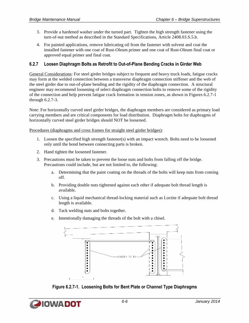
Bridge Maintenance Manual Chapter 6 – Bridge Superstructures
6-6 January 2014
3. Provide a hardened washer under the turned part. Tighten the high strength fastener using the
turn-of-nut method as described in the Standard Specifications, Article 2408.03.S.5.b.
4. For painted applications, remove lubricating oil from the fastener with solvent and coat the
installed fastener with one coat of Rust-Oleum primer and one coat of Rust-Oleum final coat or
approved equal primer and final coat.
6.2.7 Loosen Diaphragm Bolts as Retrofit to Out-of-Plane Bending Cracks in Girder Web
General Considerations: For steel girder bridges subject to frequent and heavy truck loads, fatigue cracks
may form at the welded connection between a transverse diaphragm connection stiffener and the web of
the steel girder due to out-of-plane bending and the rigidity of the diaphragm connection. A structural
engineer may recommend loosening of select diaphragm connection bolts to remove some of the rigidity
of the connection and help prevent fatigue crack formation in tension zones, as shown in Figures 6.2.7-1
through 6.2.7-3.
Note: For horizontally curved steel girder bridges, the diaphragm members are considered as primary load
carrying members and are critical components for load distribution. Diaphragm bolts for diaphragms of
horizontally curved steel girder bridges should NOT be loosened.
Procedures (diaphragms and cross frames for straight steel girder bridges):
1. Loosen the specified high strength fastener(s) with an impact wrench. Bolts need to be loosened
only until the bond between connecting parts is broken.
2. Hand tighten the loosened fastener.
3. Precautions must be taken to prevent the loose nuts and bolts from falling off the bridge.
Precautions could include, but are not limited to, the following:
a. Determining that the paint coating on the threads of the bolts will keep nuts from coming
off.
b. Providing double nuts tightened against each other if adequate bolt thread length is
available.
c. Using a liquid mechanical thread-locking material such as Loctite if adequate bolt thread
length is available.
d. Tack welding nuts and bolts together.
e. Intentionally damaging the threads of the bolt with a chisel.
Figure 6.2.7-1. Loosening Bolts for Bent Plate or Channel Type Diaphragms
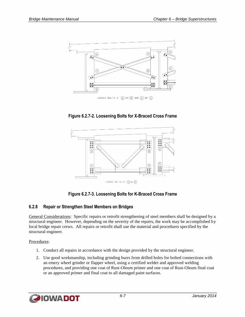
Bridge Maintenance Manual Chapter 6 – Bridge Superstructures
6-7 January 2014
Figure 6.2.7-2. Loosening Bolts for X-Braced Cross Frame
Figure 6.2.7-3. Loosening Bolts for K-Braced Cross Frame
6.2.8 Repair or Strengthen Steel Members on Bridges
General Considerations: Specific repairs or retrofit strengthening of steel members shall be designed by a
structural engineer. However, depending on the severity of the repairs, the work may be accomplished by
local bridge repair crews. All repairs or retrofit shall use the material and procedures specified by the
structural engineer.
Procedures:
1. Conduct all repairs in accordance with the design provided by the structural engineer.
2. Use good workmanship, including grinding burrs from drilled holes for bolted connections with
an emery wheel grinder or flapper wheel, using a certified welder and approved welding
procedures, and providing one coat of Rust-Oleum primer and one coat of Rust-Oleum final coat
or an approved primer and final coat to all damaged paint surfaces.
Bridge Maintenance Manual Chapter 6 – Bridge Superstructures
6-8 January 2014
6.2.9 Drill 1-inch Crack Arresting Holes at Ends of Cracks in Steel Members
General Considerations: Often, the end of a fatigue crack cannot be determined by simple visual
inspection. It is important to use a non-destructive test method such as magnetic particle testing to
establish the end point of a fatigue crack to determine the appropriate location to initiate drilling for a
crack arresting hole. An engineer should be consulted before performing any maintenance on cracked
steel members.
Procedures:
1. Use magnetic particle testing to locate the end of the fatigue crack. If the crack is visible from
both sides, determine the end point of the crack on the side where the crack has propagated the
furthest.
2. Position the center of the drill hole beyond the visible extremity of the crack so that the edge of
the hole coincides with the visible end of the crack. A 1-inch diameter hole should be used if a
bolt will not be installed in the hole.
3. Drill the hole with its axis perpendicular to the surface of the steel member; remove burrs with an
emery wheel grinder or flapper wheel.
4. At the bridge owner’s discretion, drill a 15/16 inch diameter hole and install a ⅞-inch-high
strength fastener into the hole with a hardened washer under the tightened element and a high
strength nut. Tighten the fastener using the turn-of-nut method in accordance with the Standard
Specifications, Article 2408.03.S.5.b to induce compressive stresses into the metal surrounding
the hole.
5. For painted applications where a fastener is installed in the hole, remove lubricating oil from the
fastener with a solvent, and coat the installed fastener with one coat of Rust-Oleum primer and
one coat of Rust-Oleum final coat or approved equal primer and final coat.
6. For painted applications where a fastener is not installed in the hole, paint the area of the hole,
including the interior of the hole, with one coat of Rust-Oleum primer and one coat of Rust-
Oleum final coat or approved equal primer and final coat.
6.2.10 Core Large Diameter Holes to Retrofit Fatigue Crack Prone Locations
General Considerations: Another common retrofit for fatigue cracks is to core a 2- to 4-inch-diameter
hole at the location of the crack to both encompass the tip of the crack as well as to help relieve the
restraint at the detail that may be contributing to the crack formation (See Figures 6.2.10-1, 6.2.10-2 and
6.2.10-3). An example of this application is at the weld termination of a transverse diaphragm stiffener in
the tension zone of a steel girder. Typically, the problem detail involves a situation where the stiffener is
not connected to the tension flange of the girder, as is currently required by design codes. As the
diaphragm induces load to the stiffener, the end of the stiffener attempts to bend the girder web in its
weak axis, and a crack may initiate in the girder web at the end of the web-to-stiffener weld or along the
web-to-tension-flange weld. Do not use this retrofit detail if the hole will not encompass the end of the
crack.
Procedures – Fatigue Crack Retrofit at Diaphragm Connection Stiffener:
1. Use magnetic particle testing to locate the end of the fatigue crack.
2. Using a plug from a previous hole as a guide, locate the intended position of the 3- to 4-inch-
diameter core hole in the girder web to encompass the end of the crack and encroach into the
web-to-stiffener weld and the web-to-tension flange weld by ⅛ inch.
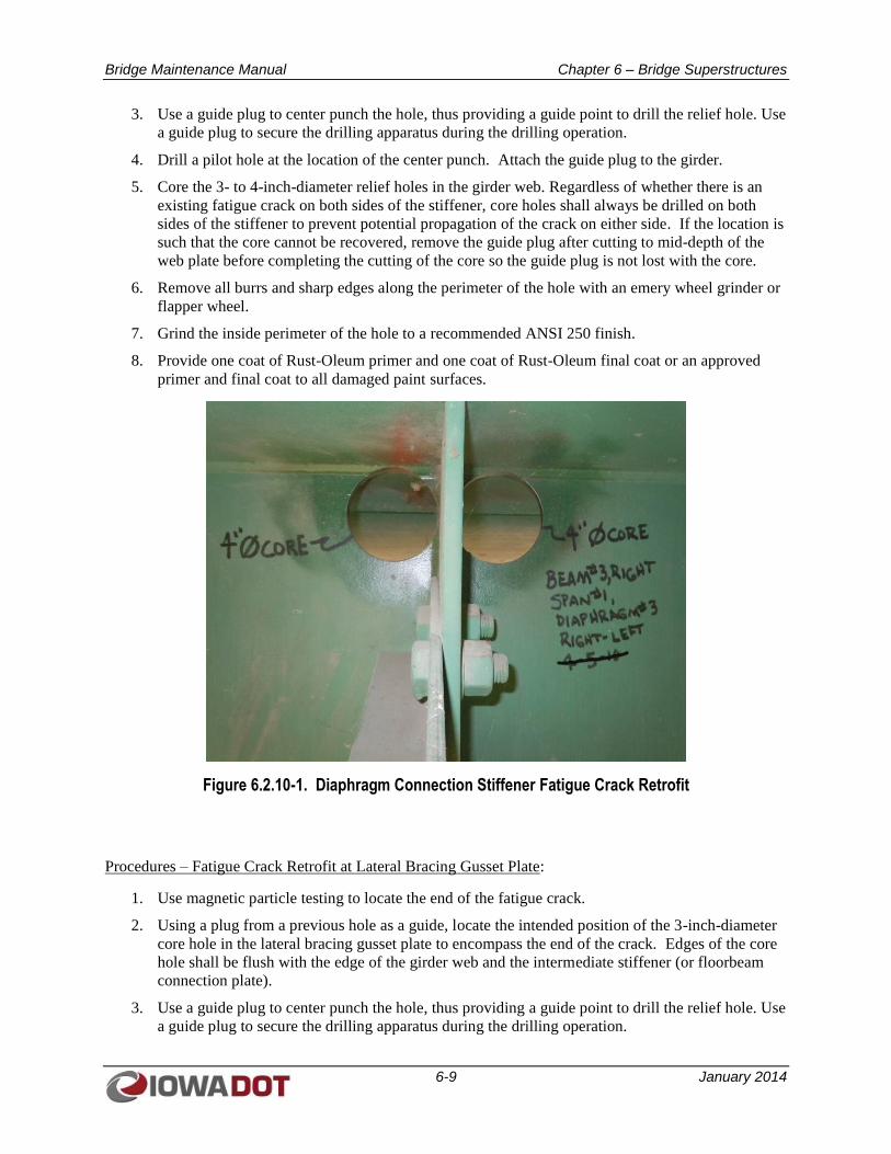
Bridge Maintenance Manual Chapter 6 – Bridge Superstructures
6-9 January 2014
3. Use a guide plug to center punch the hole, thus providing a guide point to drill the relief hole. Use
a guide plug to secure the drilling apparatus during the drilling operation.
4. Drill a pilot hole at the location of the center punch. Attach the guide plug to the girder.
5. Core the 3- to 4-inch-diameter relief holes in the girder web. Regardless of whether there is an
existing fatigue crack on both sides of the stiffener, core holes shall always be drilled on both
sides of the stiffener to prevent potential propagation of the crack on either side. If the location is
such that the core cannot be recovered, remove the guide plug after cutting to mid-depth of the
web plate before completing the cutting of the core so the guide plug is not lost with the core.
6. Remove all burrs and sharp edges along the perimeter of the hole with an emery wheel grinder or
flapper wheel.
7. Grind the inside perimeter of the hole to a recommended ANSI 250 finish.
8. Provide one coat of Rust-Oleum primer and one coat of Rust-Oleum final coat or an approved
primer and final coat to all damaged paint surfaces.
Figure 6.2.10-1. Diaphragm Connection Stiffener Fatigue Crack Retrofit
Procedures – Fatigue Crack Retrofit at Lateral Bracing Gusset Plate:
1. Use magnetic particle testing to locate the end of the fatigue crack.
2. Using a plug from a previous hole as a guide, locate the intended position of the 3-inch-diameter
core hole in the lateral bracing gusset plate to encompass the end of the crack. Edges of the core
hole shall be flush with the edge of the girder web and the intermediate stiffener (or floorbeam
connection plate).
3. Use a guide plug to center punch the hole, thus providing a guide point to drill the relief hole. Use
a guide plug to secure the drilling apparatus during the drilling operation.
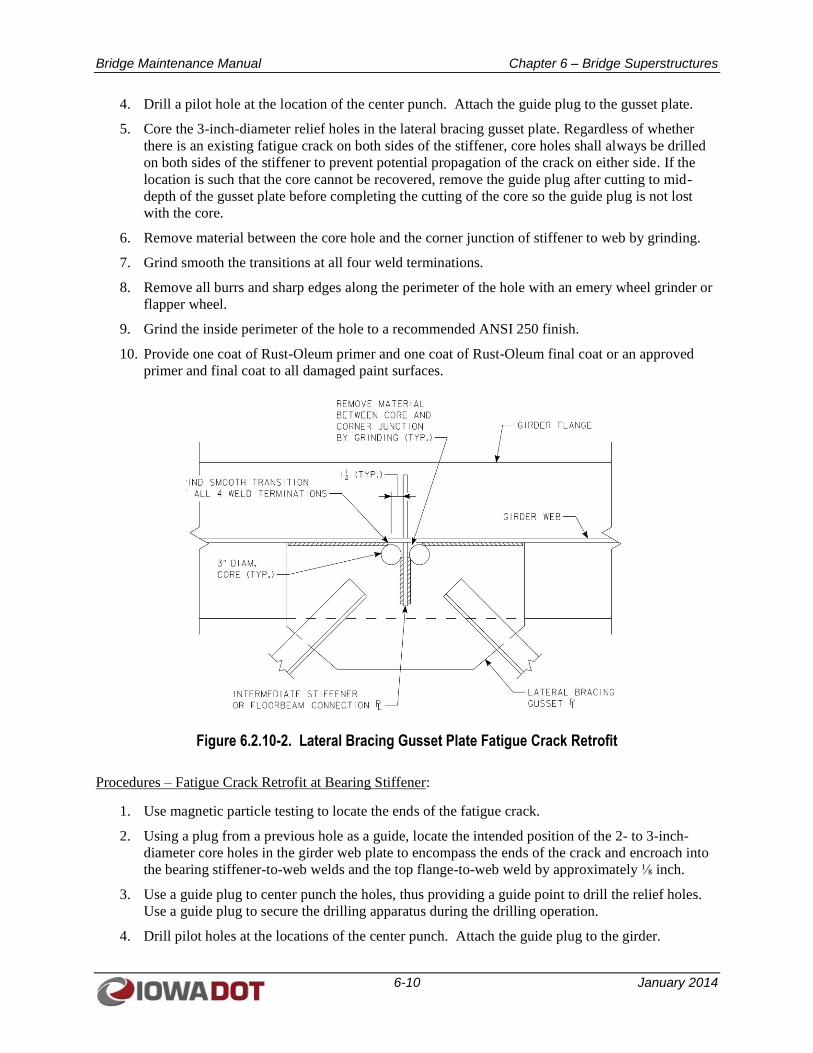
Bridge Maintenance Manual Chapter 6 – Bridge Superstructures
6-10 January 2014
4. Drill a pilot hole at the location of the center punch. Attach the guide plug to the gusset plate.
5. Core the 3-inch-diameter relief holes in the lateral bracing gusset plate. Regardless of whether
there is an existing fatigue crack on both sides of the stiffener, core holes shall always be drilled
on both sides of the stiffener to prevent potential propagation of the crack on either side. If the
location is such that the core cannot be recovered, remove the guide plug after cutting to mid-
depth of the gusset plate before completing the cutting of the core so the guide plug is not lost
with the core.
6. Remove material between the core hole and the corner junction of stiffener to web by grinding.
7. Grind smooth the transitions at all four weld terminations.
8. Remove all burrs and sharp edges along the perimeter of the hole with an emery wheel grinder or
flapper wheel.
9. Grind the inside perimeter of the hole to a recommended ANSI 250 finish.
10. Provide one coat of Rust-Oleum primer and one coat of Rust-Oleum final coat or an approved
primer and final coat to all damaged paint surfaces.
Figure 6.2.10-2. Lateral Bracing Gusset Plate Fatigue Crack Retrofit
Procedures – Fatigue Crack Retrofit at Bearing Stiffener:
1. Use magnetic particle testing to locate the ends of the fatigue crack.
2. Using a plug from a previous hole as a guide, locate the intended position of the 2- to 3-inch-
diameter core holes in the girder web plate to encompass the ends of the crack and encroach into
the bearing stiffener-to-web welds and the top flange-to-web weld by approximately ⅛ inch.
3. Use a guide plug to center punch the holes, thus providing a guide point to drill the relief holes.
Use a guide plug to secure the drilling apparatus during the drilling operation.
4. Drill pilot holes at the locations of the center punch. Attach the guide plug to the girder.
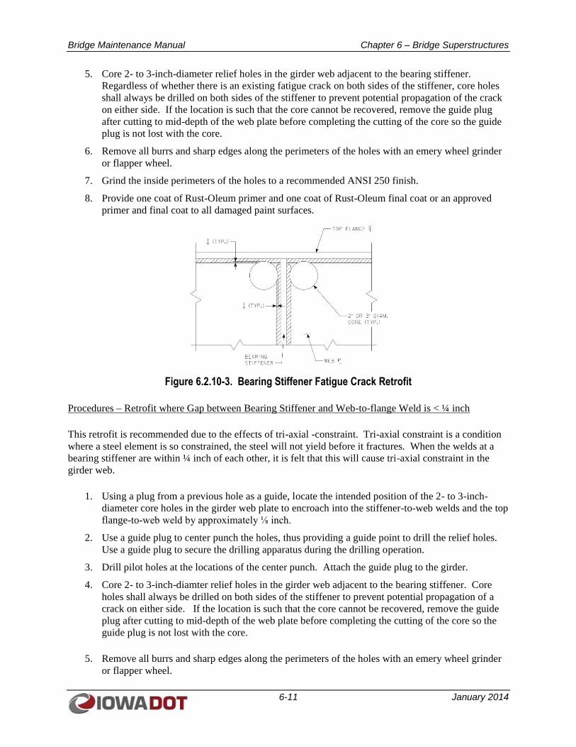
Bridge Maintenance Manual Chapter 6 – Bridge Superstructures
6-11 January 2014
5. Core 2- to 3-inch-diameter relief holes in the girder web adjacent to the bearing stiffener.
Regardless of whether there is an existing fatigue crack on both sides of the stiffener, core holes
shall always be drilled on both sides of the stiffener to prevent potential propagation of the crack
on either side. If the location is such that the core cannot be recovered, remove the guide plug
after cutting to mid-depth of the web plate before completing the cutting of the core so the guide
plug is not lost with the core.
6. Remove all burrs and sharp edges along the perimeters of the holes with an emery wheel grinder
or flapper wheel.
7. Grind the inside perimeters of the holes to a recommended ANSI 250 finish.
8. Provide one coat of Rust-Oleum primer and one coat of Rust-Oleum final coat or an approved
primer and final coat to all damaged paint surfaces.
Figure 6.2.10-3. Bearing Stiffener Fatigue Crack Retrofit
Procedures – Retrofit where Gap between Bearing Stiffener and Web-to-flange Weld is < ¼ inch
This retrofit is recommended due to the effects of tri-axial -constraint. Tri-axial constraint is a condition
where a steel element is so constrained, the steel will not yield before it fractures. When the welds at a
bearing stiffener are within ¼ inch of each other, it is felt that this will cause tri-axial constraint in the
girder web.
1. Using a plug from a previous hole as a guide, locate the intended position of the 2- to 3-inch-
diameter core holes in the girder web plate to encroach into the stiffener-to-web welds and the top
flange-to-web weld by approximately ⅛ inch.
2. Use a guide plug to center punch the holes, thus providing a guide point to drill the relief holes.
Use a guide plug to secure the drilling apparatus during the drilling operation.
3. Drill pilot holes at the locations of the center punch. Attach the guide plug to the girder.
4. Core 2- to 3-inch-diamter relief holes in the girder web adjacent to the bearing stiffener. Core
holes shall always be drilled on both sides of the stiffener to prevent potential propagation of a
crack on either side. If the location is such that the core cannot be recovered, remove the guide
plug after cutting to mid-depth of the web plate before completing the cutting of the core so the
guide plug is not lost with the core.
5. Remove all burrs and sharp edges along the perimeters of the holes with an emery wheel grinder
or flapper wheel.
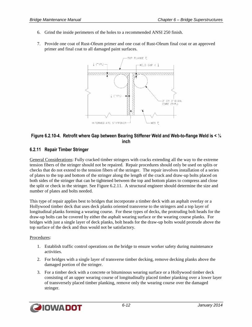
Bridge Maintenance Manual Chapter 6 – Bridge Superstructures
6-12 January 2014
6. Grind the inside perimeters of the holes to a recommended ANSI 250 finish.
7. Provide one coat of Rust-Oleum primer and one coat of Rust-Oleum final coat or an approved
primer and final coat to all damaged paint surfaces.
Figure 6.2.10-4. Retrofit where Gap between Bearing Stiffener Weld and Web-to-flange Weld is < ¼ inch
6.2.11 Repair Timber Stringer
General Considerations: Fully cracked timber stringers with cracks extending all the way to the extreme
tension fibers of the stringer should not be repaired. Repair procedures should only be used on splits or
checks that do not extend to the tension fibers of the stringer. The repair involves installation of a series
of plates to the top and bottom of the stringer along the length of the crack and draw-up bolts placed on
both sides of the stringer that can be tightened between the top and bottom plates to compress and close
the split or check in the stringer. See Figure 6.2.11. A structural engineer should determine the size and
number of plates and bolts needed.
This type of repair applies best to bridges that incorporate a timber deck with an asphalt overlay or a
Hollywood timber deck that uses deck planks oriented transverse to the stringers and a top layer of
longitudinal planks forming a wearing course. For these types of decks, the protruding bolt heads for the
draw-up bolts can be covered by either the asphalt wearing surface or the wearing course planks. For
bridges with just a single layer of deck planks, bolt heads for the draw-up bolts would protrude above the
top surface of the deck and thus would not be satisfactory.
Procedures:
1. Establish traffic control operations on the bridge to ensure worker safety during maintenance
activities.
2. For bridges with a single layer of transverse timber decking, remove decking planks above the
damaged portion of the stringer.
3. For a timber deck with a concrete or bituminous wearing surface or a Hollywood timber deck
consisting of an upper wearing course of longitudinally placed timber planking over a lower layer
of transversely placed timber planking, remove only the wearing course over the damaged
stringer.
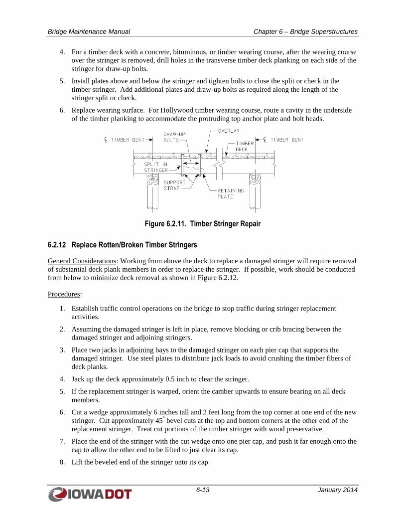
Bridge Maintenance Manual Chapter 6 – Bridge Superstructures
6-13 January 2014
4. For a timber deck with a concrete, bituminous, or timber wearing course, after the wearing course
over the stringer is removed, drill holes in the transverse timber deck planking on each side of the
stringer for draw-up bolts.
5. Install plates above and below the stringer and tighten bolts to close the split or check in the
timber stringer. Add additional plates and draw-up bolts as required along the length of the
stringer split or check.
6. Replace wearing surface. For Hollywood timber wearing course, route a cavity in the underside
of the timber planking to accommodate the protruding top anchor plate and bolt heads.
Figure 6.2.11. Timber Stringer Repair
6.2.12 Replace Rotten/Broken Timber Stringers
General Considerations: Working from above the deck to replace a damaged stringer will require removal
of substantial deck plank members in order to replace the stringer. If possible, work should be conducted
from below to minimize deck removal as shown in Figure 6.2.12.
Procedures:
1. Establish traffic control operations on the bridge to stop traffic during stringer replacement
activities.
2. Assuming the damaged stringer is left in place, remove blocking or crib bracing between the
damaged stringer and adjoining stringers.
3. Place two jacks in adjoining bays to the damaged stringer on each pier cap that supports the
damaged stringer. Use steel plates to distribute jack loads to avoid crushing the timber fibers of
deck planks.
4. Jack up the deck approximately 0.5 inch to clear the stringer.
5. If the replacement stringer is warped, orient the camber upwards to ensure bearing on all deck
members.
6. Cut a wedge approximately 6 inches tall and 2 feet long from the top corner at one end of the new
stringer. Cut approximately 45° bevel cuts at the top and bottom corners at the other end of the
replacement stringer. Treat cut portions of the timber stringer with wood preservative.
7. Place the end of the stringer with the cut wedge onto one pier cap, and push it far enough onto the
cap to allow the other end to be lifted to just clear its cap.
8. Lift the beveled end of the stringer onto its cap.
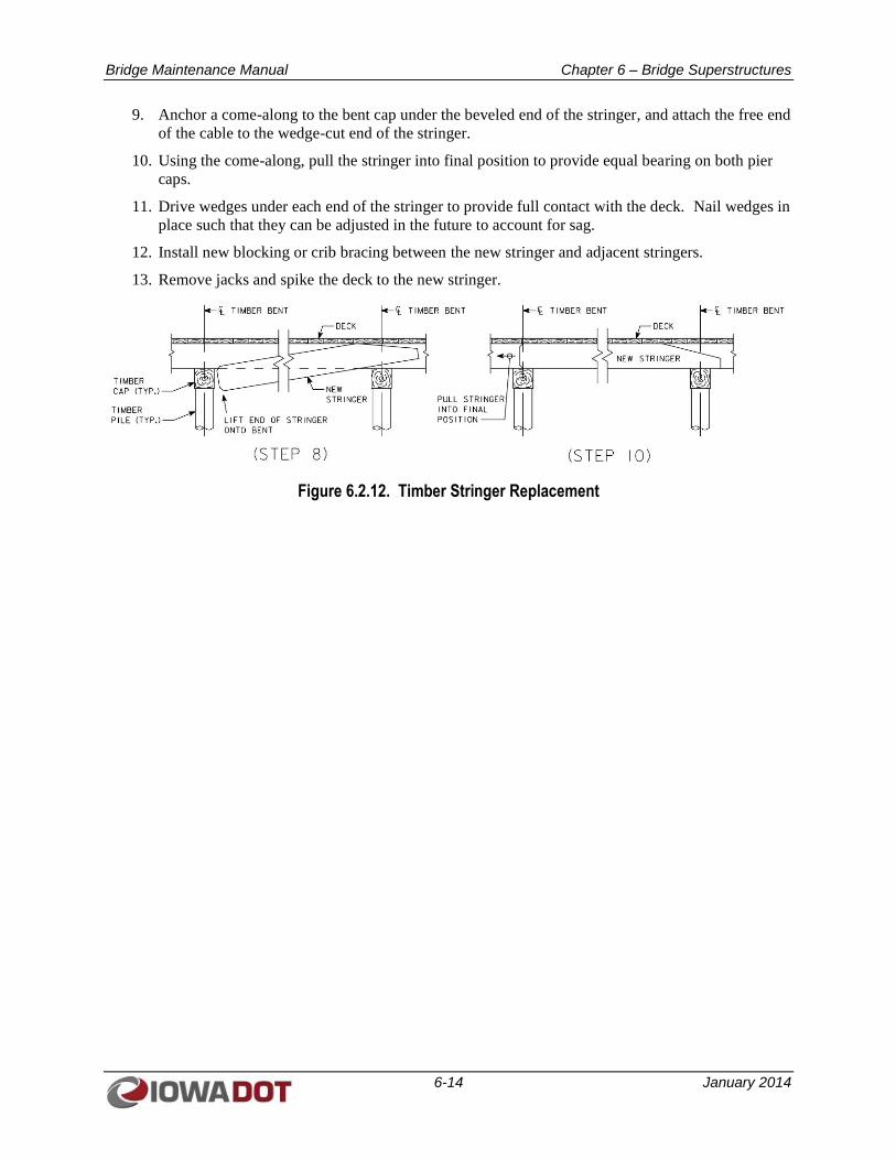
Bridge Maintenance Manual Chapter 6 – Bridge Superstructures
6-14 January 2014
9. Anchor a come-along to the bent cap under the beveled end of the stringer, and attach the free end
of the cable to the wedge-cut end of the stringer.
10. Using the come-along, pull the stringer into final position to provide equal bearing on both pier
caps.
11. Drive wedges under each end of the stringer to provide full contact with the deck. Nail wedges in
place such that they can be adjusted in the future to account for sag.
12. Install new blocking or crib bracing between the new stringer and adjacent stringers.
13. Remove jacks and spike the deck to the new stringer.
Figure 6.2.12. Timber Stringer Replacement
Bridge Maintenance Manual Chapter 7 – Bridge Substructures
7-1 January 2014
CHAPTER 7
BRIDGE SUBSTRUCTURES
7.1 COMMON PROBLEMS AND CONSEQUENCES OF POOR MAINTENANCE
Common problems and causes of deterioration associated with bridge substructure components include
typical damage due to overload conditions, such as abutment rotation or pier tilting from excess lateral
soil loads; damage from flood debris impact, vessel collision, or vehicle impact; settlement and scour at
foundations; and material deterioration generally caused by poor control of roadway or bridge runoff.
7.1.1 Reinforced Concrete Substructures
Reinforced concrete substructures may experience cracking, spalling, delamination, and corroding of
reinforcing steel. Movement, rotation, or settlement of an abutment or wingwall may initiate damage, and
once cracks form and allow intrusion of water and chlorides, advanced deterioration may follow as
reinforcing steel corrodes and expands further. Pier elements exposed to bridge runoff due to leaking
expansion joints can experience similar deterioration. In addition, bridge bearings that have failed and
no longer slide or rotate as intended can impart added loads to concrete substructures and cause spalling
or cracking as the unintended loads are transmitted to substructure members. Reinforced concrete
substructure members may also experience damage from impact of flood debris, vessels, or vehicles.
7.1.2 Steel Trestle
Steel trestle supports and abutments consisting of steel piles with steel sheet pile backwalls and wingwalls
are less rigid substructure elements when compared to reinforced concrete substructures and are more
susceptible to lateral movement due to unbalanced soil loads or locked-up bridge bearings. Such
movements not only can overstress steel members but also can overstress bolted connections and cause
welds to crack. Steel substructures are also susceptible to corrosion if the protective paint coating fails.
Failed coatings and loss of section at the waterline where steel piles experience alternating wetting cycles
are common problems.
7.1.3 Timber Trestle
Timber trestles and abutments are subject to rot; insect damage; material failures such as splits, checks,
and shakes; and natural imperfections such as knots. Excessive lateral soil loads at abutment wingwalls
or backwalls may fail the timber planks retaining the soil. Rot of timber piles is common particularly at
the waterline where cyclical wetting cycles occur.
7.2 BRIDGE SUBSTRUCTURE MAINTENANCE AND REPAIR PROCEDURES
7.2.1 Wash Bridge Beam Seats
General Considerations: Regular cleaning of bridge beam seats at abutments and pier caps should be
performed to remove accumulated dirt and debris that can trap moisture and promote concrete
deterioration, steel corrosion, and timber rot. Cleaning also flushes concentrations of corrosive roadway
salts. Generally, washing of bridge beam seats should be scheduled annually at a minimum and should
coincide with bridge joint and deck cleaning activities at the end of normal winter operations.
Bridge Maintenance Manual Chapter 7 – Bridge Substructures
7-2 January 2014
Procedures:
1. Use shovels, brooms, hand scrapers, and other hand tools to physically remove large
accumulations of roadway debris, dirt, bird nesting material, and bird excrement from beam seats.
2. Using a source of fresh water free of contaminants, remove salt contaminants, dirt, and other
detrimental foreign matter with a high pressure wash. Use a water flow rate of at least 5 gallons
per minute and a maximum water pressure of 1,000 psi.
7.2.2 Seal Bridge Beam Seats
General Considerations: Sealing bridge beam seats following beam seat washing is effective to minimize
chloride intrusions into concrete.
Procedures:
1. Remove loose or unsound material by hand methods or sandblasting.
2. At a minimum, use a light sandblast (brush blast) followed by air cleaning on all designated
surfaces to receive concrete sealer. Clean sufficiently to remove road film and contamination
from existing concrete surfaces. Ensure that all surfaces to be sealed are clean, sound, and dry.
3. Apply sealer material in accordance with the manufacturer’s recommendations. Sealing material
and coverage rates shall conform with requirements of Materials I.M. 491.12.
7.2.3 Repair Tops of Abutment Backwalls with Concrete
General Considerations: The tops of abutment backwalls may deteriorate due to mechanical action of
approach slab rotation against the backwall combined with intrusion of chloride-laden bridge runoff into
the joint between the abutment and the approach slab. In addition, deterioration of expansion joint
components that are embedded into the abutment backwall may contribute to deterioration. Refer to
Figure 1.3.2 for repairs associated with damaged sliding plate expansion joints at abutments.
The repairs described below apply to abutment backwall deterioration limited to the area above the
paving notch of abutments.
Procedures:
1. Establish traffic control operations on the bridge to ensure worker safety during maintenance
activities.
2. Remove concrete down to sound concrete above the paving notch. Limit jackhammer size to a
nominal 30-pound class, and limit chipping hammer size to 15-pound class. Where existing
reinforcing steel is sound, incorporate the existing reinforcing steel into new work.
3. Clean or remove corroded reinforcing steel. If needed, replace damaged reinforcing steel with
new bars and securely tie new reinforcing steel into place. Touch up exposed surfaces of epoxy
coated reinforcing steel with an approved coating material. Replace unsound vertical reinforcing
steel by drilling and grouting new vertical dowels into the existing backwall. Use a polymer
grout system in conformance with Materials I.M. 491.11. The depth of the grout hole shall be in
accordance with the grout manufacturer’s recommendations.
4. Clean the repair area by sandblasting. Protect epoxy coated reinforcing from the cleaning
process. Clean epoxy coated reinforcing with hand tools that will not damage the epoxy coating.
Follow with an air blast of oil-free compressed air.
Bridge Maintenance Manual Chapter 7 – Bridge Substructures
7-3 January 2014
5. Install forms for new concrete repair. Ensure that the existing concrete surface is dry before
placing new concrete.
6. Use a Class O, C, M, or a rapid set mix as appropriate for the site conditions for the new concrete
used for repairs. Place concrete according to the Standard Specifications, Article 2403.03.C.
7. Apply a white pigmented curing compound to the concrete immediately after removing forms.
The application rate shall be 100 square feet per gallon.
7.2.4 Epoxy Inject Cracked Wingwalls, Abutments, and Piers
General Considerations: Localized cracks in wingwalls, abutments, and piers may be addressed by
pressure injecting cracks with epoxy. Note that for “working” cracks, the underlying cause of the
cracking should be determined first so that corrective action can be taken to alleviate the cause of the
cracking.
Procedures:
1. For work adjacent to active traffic, establish traffic control operations to ensure worker safety
during maintenance activities.
2. Clean the surface area of the crack for approximately 0.5 inch on each side of the crack with a
wire brush (mechanical grinders may fill the crack with unwanted dust).
3. Where concrete surfaces adjacent to the crack are deteriorated, route the crack in a V-groove
sufficient to reach sound concrete.
4. Remove contaminants by high pressure water, oil-free compressed air, or vacuum. When using
water to clean a crack, blow out the crack with oil-free compressed air and allow the repair area
to dry naturally before injecting it with moisture-sensitive epoxies.
5. Using a manufacturer- approved adhesive, install epoxy injection port adapters (surface mounted
or socket mounted). Spacing of port adapters will depend on the length and width of the crack.
6. For horizontal cracks, mark the location of the widest part of the crack.
7. Trowel a cap seal over the crack and around bases of the port adapters to contain pressure
injected epoxy. Allow the cap seal and port adapter adhesives to properly cure.
8. For vertical cracks, start injection of epoxy at the lowest port adapter. For horizontal cracks, start
injection at the widest part of the crack. Begin injection and continue until refusal or until epoxy
vents from an adjacent port. When an adjacent port bleeds, cap the port being injected and move
to the adjacent port. Continue injection in a similar fashion, working along the length of the
crack.
9. For hairline cracks not suited for injecting until refusal, increase the injecting pressure to
approximately 200 psi as needed. However, monitor injection to prevent a blowout of the cap
seal or ports.
10. Upon completion of the injection process and curing of epoxy, remove the cap seal and ports by
cutting off flush.
7.2.5 Concrete Repair (Shallow and Regular) at Wingwalls, Abutments, and Piers
General Considerations: For spalls, delaminations, and general deterioration in wingwalls, abutments,
and piers that are more extensive than simple cracks, concrete deterioration may be repaired as either
shallow or regular concrete repairs in accordance with the Standard Specifications, Article 2426, for
Structural Concrete Repair.
Bridge Maintenance Manual Chapter 7 – Bridge Substructures
7-4 January 2014
Procedures:
1. For work adjacent to active traffic, establish traffic control operations to ensure worker safety
during maintenance activities.
2. Remove unsound concrete from the damaged area of the substructure element, extending the
limits of the damaged area until sound concrete is encountered. Limit jackhammer size to a
nominal 30-pound class, and limit chipping hammer size to 15-pound class.
3. Using a chop saw, provide a 0.75-inch-deep saw cut around the perimeter of the damaged area to
square up the repair area and eliminate feathered edges. Jackhammer or use hand tools as needed
to extend removals to the saw cut lines.
4. Clean or remove corroded reinforcing steel. If needed, replace damaged reinforcing steel with
new bars and securely tie new reinforcing steel into place. Touch up exposed surfaces of epoxy
coated reinforcing steel with an approved coating material.
5. Clean the repair area by sandblasting. Protect epoxy coated reinforcing from the cleaning
process. Clean epoxy coated reinforcing with hand tools that will not damage the epoxy coating.
Follow with an air blast of oil-free compressed air.
6. For shallow repairs (0.75 to 1.5 inches deep where no form work is used to support the patching
material), first apply a bonding grout conforming to the Standard Specifications, Article
2426.02.B.1; ensure that the repair area is dry before placing grout. Concrete for shallow repairs
shall conform with the Standard Specifications, Table 2426.02-1. Place concrete before the grout
dries out. For shallow repair areas where the patching material cannot support itself, forms may
be needed, and in these areas, no bonding grout is required.
7. For regular repairs (a minimum depth of 1.5 inches or 0.75 inch behind an unbonded reinforcing
bar and where form work is used), no bonding grout is required. Use a Class O concrete mix for
the repair concrete. Ensure that the concrete surface is dry before placing new concrete (Standard
Specifications, Article 2403.03.I.1). When repairing a vertical face, place the patch in heights not
to exceed 4 feet; provide access ports in the forms at 4-foot intervals for concrete placement and
vibration.
8. Apply a white pigmented curing compound to the concrete immediately following concrete
finishing or immediately after removing forms. The application rate shall be 100 square feet per
gallon.
7.2.6 Reconstruct Paving Notch at Integral Abutments
General Considerations: This type of work on stub abutments generally requires extensive reconstruction
of the upper portion of the abutment backwall, which involves removal and replacement of an expansion
device as well as the paving notch. As such, this work is generally contracted to outside forces. General
procedures for replacement of a paving notch on an integral abutment are listed below.
Procedures:
1. Establish traffic control operations on the bridge and approach slabs to ensure worker safety
during maintenance activities. For a two-lane bridge with traffic in both directions, full closure of
the bridge would likely be required. For a two-lane bridge with traffic in one direction only, the
work could be staged to do one lane at a time, which would allow for staged replacement of the
approach slabs and the paving notch.
2. Remove the bridge approach slab for a minimum of 5 feet (measured along centerline of
approach roadway) beyond the end of bridge floor according to the Standard Specifications,
Bridge Maintenance Manual Chapter 7 – Bridge Substructures
7-5 January 2014
Article 2529.03.C.4. For staged construction, remove one lane of approach slab and provide
support for the vertical face of the excavated area along the removal line to support traffic during
construction.
3. Excavate behind the abutment to below the paving notch.
4. Remove the existing paving notch; removals should also create an 8 inch by 1 ½ inch keyway in
the abutment for the new paving notch with keyway removals initiated by ¾ inch sawcuts. Limit
jackhammer size to a nominal 30-pound class, and limit chipping hammer size to 15-pound class.
Where existing reinforcing steel is sound, incorporate the existing reinforcing steel into new
work.
5. Clean or remove corroded reinforcing steel. New top and bottom paving notch reinforcing steel
shall be provided by drilling and grouting new bars into the abutment. Use a polymer grout
system in conformance with Materials I.M. 491.11. The depth of the grout hole shall be in
accordance with the grout manufacturer’s recommendations. Securely tie new horizontal
reinforcing steel for the paving notch into place. Touch up the exposed surfaces of epoxy coated
reinforcing steel with an approved coating material.
6. The existing concrete surfaces shall be roughened to ensure a good bond with new concrete.
Clean the repair area by sandblasting. Protect epoxy coated reinforcing from the cleaning
process. Clean epoxy coated reinforcing with hand tools that will not damage the epoxy coating.
Follow with an air blast of oil-free compressed air.
7. Compact granular backfill below paving notch before installing forms for new the abutment
backwall and/or paving notch. Ensure that the existing concrete surface is dry before placing new
concrete.
8. Use a Class C concrete mix for the new concrete. Place concrete according to the Standard
Specifications, Article 2403.03.C. Concrete slump requirements shall be as specified in Standard
Specifications, Article 2403.02.B.2.a.
9. Apply a white pigmented curing compound to the concrete immediately after removing forms.
The application rate shall be 100 square feet per gallon.
10. Replace and compact the backfill behind the abutment according to the Standard Specifications,
Article 2402.03.I. Place and compact a 1-foot minimum depth of modified subbase under the
new approach slab according to the Standard Specifications Article, 2115.03.B.4; extend the
subbase to a point 3 feet from the approach slab removal line. In the absence of site-specific
approach slab details, reinforce the 1-foot thick approach slab with #6 bars at 1-foot centers
longitudinally on top, #9 bars at 1-foot centers longitudinally on the bottom and #5 bars at 1-foot
centers transversely top and bottom. Provide 2’-2” long, #6 tie bars at 1-foot centers, drilled and
grouted into the existing approach pavement at mid-depth of the pavement slab along the removal
line; embed the tie bars 10 inches minimum into the existing approach pavement concrete.
Provide a joint between the end of bridge floor and the new approach slab sized in accordance
with Standard Road Plan RK-19A. Use Class C concrete in accordance with the Standard
Specifications, Article 2301.03.R.4. Form and pour the new approach slab section according to
Standard Specifications, Article 2529.03.H. Upon final curing of approach slab concrete, reopen
the completed portion to traffic.
11. For staged construction, repeat steps 2-10 for the remaining portion of approach slab and paving
notch.
Bridge Maintenance Manual Chapter 7 – Bridge Substructures
7-6 January 2014
7.2.7 Repair Bridge Seats Under Bearings
General Considerations: The following procedures assume that deterioration below beam seats is
extensive, where there is possible loss of support. Repair procedures assume that jacking of the beams to
support bearing loads will be required while repairs are completed.
Procedures:
1. Provide traffic control or auxiliary shoring of affected bridge members as required for bridge seat
repair activities under bearings.
2. Position hydraulic jacks adjacent to existing bearings at jacking stiffener locations, or position
jacks at an auxiliary support bent adjacent to existing bearing supports.
3. If required, disconnect barrier sliding plates, expansion joints, or conduit that are continuous
through joints at lifting point so as to prevent damage during jacking operations to these
secondary components.
4. While simultaneously jacking adjacent beam lines at the same substructure support, lift all girders
only as required to relieve load from bearings (a maximum of 0.5 inch).
5. Use lock-off nuts on jacks or blocking to support loads so that hydraulic pressure does not need to
be maintained during beam seat repair operations.
6. Remove unsound concrete from the damaged area of the bridge seats, extending the limits of the
damaged area until sound concrete is encountered. Limit jackhammer size to a nominal 30-pound
class, and limit chipping hammer size to 15-pound class.
7. Using a chop saw, provide a 0.75-inch-deep saw cut around the perimeter of the damaged area to
square up the repair area and eliminate feathered edges. Jackhammer as needed to extend
removals to the saw cut lines.
8. Clean or remove corroded reinforcing steel. Replace damaged reinforcing steel with new bars and
securely tie new reinforcing steel into place. If necessary, drill and grout new dowels into the
sound concrete using a polymer grout system in conformance with Materials I.M. 491.11. The
depth of the grout hole shall be in accordance with the grout manufacturer’s recommendations. At
the owner’s preference, zinc anodes may be installed to inhibit corrosion of the reinforcing.
9. Clean the repair area by sandblasting. Protect epoxy coated reinforcing from the cleaning
process. Clean epoxy coated reinforcing with hand tools that will not damage the epoxy coating.
Follow with an air blast of oil-free compressed air.
10. Form the repair area for receiving new concrete. Ideally, a Class O concrete mix for the repair
concrete (Standard Specifications, Article 2426.02.B.2.b) should be used. Ensure that the existing
concrete surface is dry before placing new concrete (Standard Specifications, Article
2403.03.I.1).
11. Apply a white pigmented curing compound to the concrete immediately following concrete
finishing or immediately after removing forms. The application rate shall be 100 square feet per
gallon.
12. Allow new concrete to reach the specified concrete strength (3000 psi minimum) prior to
transferring bearing load to reconstructed beam seats. Ensure that bearings are properly set to
adjust for temperature prior to releasing the jacking load.
13. Slowly release hydraulic jacks to reload bearing seats.
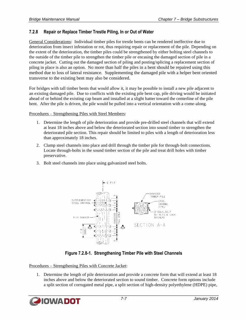
Bridge Maintenance Manual Chapter 7 – Bridge Substructures
7-7 January 2014
7.2.8 Repair or Replace Timber Trestle Piling, In or Out of Water
General Considerations: Individual timber piles for trestle bents can be rendered ineffective due to
deterioration from insect infestation or rot, thus requiring repair or replacement of the pile. Depending on
the extent of the deterioration, the timber piles could be strengthened by either bolting steel channels to
the outside of the timber pile to strengthen the timber pile or encasing the damaged section of pile in a
concrete jacket. Cutting out the damaged section of piling and posting/splicing a replacement section of
piling in place is also an option. No more than half the piles in a bent should be repaired using this
method due to loss of lateral resistance. Supplementing the damaged pile with a helper bent oriented
transverse to the existing bent may also be considered.
For bridges with tall timber bents that would allow it, it may be possible to install a new pile adjacent to
an existing damaged pile. Due to conflicts with the existing pile bent cap, pile driving would be initiated
ahead of or behind the existing cap beam and installed at a slight batter toward the centerline of the pile
bent. After the pile is driven, the pile would be pulled into a vertical orientation with a come-along.
Procedures – Strengthening Piles with Steel Members:
1. Determine the length of pile deterioration and provide pre-drilled steel channels that will extend
at least 18 inches above and below the deteriorated section into sound timber to strengthen the
deteriorated pile section. This repair should be limited to piles with a length of deterioration less
than approximately 18 inches.
2. Clamp steel channels into place and drill through the timber pile for through-bolt connections.
Locate through-bolts in the sound timber section of the pile and treat drill holes with timber
preservative.
3. Bolt steel channels into place using galvanized steel bolts.
Figure 7.2.8-1. Strengthening Timber Pile with Steel Channels
Procedures – Strengthening Piles with Concrete Jacket:
1. Determine the length of pile deterioration and provide a concrete form that will extend at least 18
inches above and below the deteriorated section to sound timber. Concrete form options include
a split section of corrugated metal pipe, a split section of high-density polyethylene (HDPE) pipe,
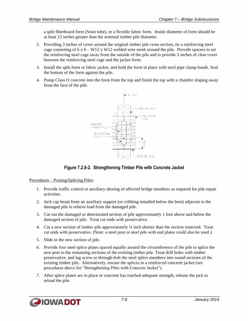
Bridge Maintenance Manual Chapter 7 – Bridge Substructures
7-8 January 2014
a split fiberboard form (Sono tube), or a flexible fabric form. Inside diameter of form should be
at least 12 inches greater than the nominal timber pile diameter.
2. Providing 3 inches of cover around the original timber pile cross section, tie a reinforcing steel
cage consisting of 6 x 6 – W12 x W12 welded wire mesh around the pile. Provide spacers to set
the reinforcing steel cage away from the outside of the pile and to provide 3 inches of clear cover
between the reinforcing steel cage and the jacket form.
3. Install the split form or fabric jacket, and hold the form in place with steel pipe clamp bands. Seal
the bottom of the form against the pile.
4. Pump Class O concrete into the form from the top and finish the top with a chamfer sloping away
from the face of the pile.
Figure 7.2.8-2. Strengthening Timber Pile with Concrete Jacket
Procedures – Posting/Splicing Piles:
1. Provide traffic control or auxiliary shoring of affected bridge members as required for pile repair
activities.
2. Jack cap beam from an auxiliary support (or cribbing installed below the bent) adjacent to the
damaged pile to relieve load from the damaged pile.
3. Cut out the damaged or deteriorated section of pile approximately 1 foot above and below the
damaged section of pile. Treat cut ends with preservative.
4. Cut a new section of timber pile approximately ¼ inch shorter than the section removed. Treat
cut ends with preservative. (Note: a steel post or steel pile with end plates could also be used.)
5. Slide in the new section of pile.
6. Provide four steel splice plates spaced equally around the circumference of the pile to splice the
new post to the remaining sections of the existing timber pile. Treat drill holes with timber
preservative, and lag screw or through-bolt the steel splice members into sound sections of the
existing timber pile. Alternatively, encase the splices in a reinforced concrete jacket (see
procedures above for “Strengthening Piles with Concrete Jacket”).
7. After splice plates are in place or concrete has reached adequate strength, release the jack to
reload the pile.
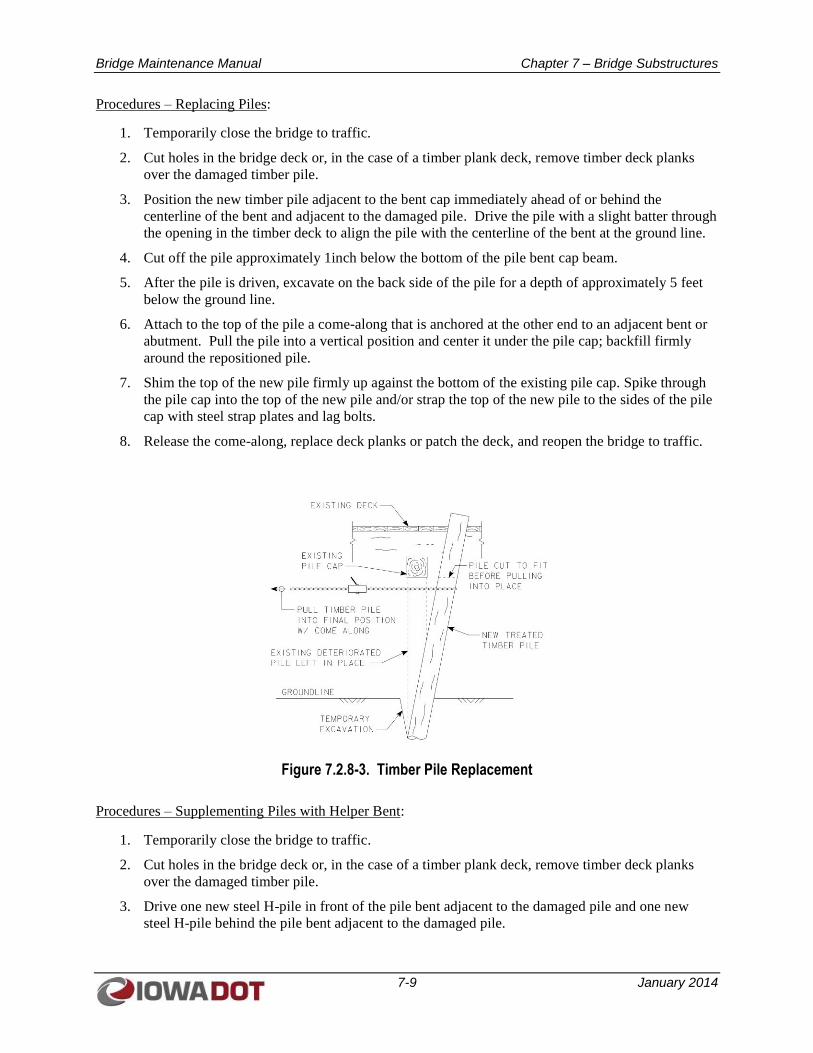
Bridge Maintenance Manual Chapter 7 – Bridge Substructures
7-9 January 2014
Procedures – Replacing Piles:
1. Temporarily close the bridge to traffic.
2. Cut holes in the bridge deck or, in the case of a timber plank deck, remove timber deck planks
over the damaged timber pile.
3. Position the new timber pile adjacent to the bent cap immediately ahead of or behind the
centerline of the bent and adjacent to the damaged pile. Drive the pile with a slight batter through
the opening in the timber deck to align the pile with the centerline of the bent at the ground line.
4. Cut off the pile approximately 1inch below the bottom of the pile bent cap beam.
5. After the pile is driven, excavate on the back side of the pile for a depth of approximately 5 feet
below the ground line.
6. Attach to the top of the pile a come-along that is anchored at the other end to an adjacent bent or
abutment. Pull the pile into a vertical position and center it under the pile cap; backfill firmly
around the repositioned pile.
7. Shim the top of the new pile firmly up against the bottom of the existing pile cap. Spike through
the pile cap into the top of the new pile and/or strap the top of the new pile to the sides of the pile
cap with steel strap plates and lag bolts.
8. Release the come-along, replace deck planks or patch the deck, and reopen the bridge to traffic.
Figure 7.2.8-3. Timber Pile Replacement
Procedures – Supplementing Piles with Helper Bent:
1. Temporarily close the bridge to traffic.
2. Cut holes in the bridge deck or, in the case of a timber plank deck, remove timber deck planks
over the damaged timber pile.
3. Drive one new steel H-pile in front of the pile bent adjacent to the damaged pile and one new
steel H-pile behind the pile bent adjacent to the damaged pile.
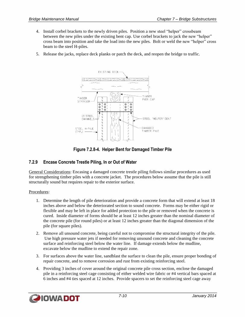
Bridge Maintenance Manual Chapter 7 – Bridge Substructures
7-10 January 2014
4. Install corbel brackets to the newly driven piles. Position a new steel “helper” crossbeam
between the new piles under the existing bent cap. Use corbel brackets to jack the new “helper”
cross beam into position and take the load into the new piles. Bolt or weld the new “helper” cross
beam to the steel H-piles.
5. Release the jacks, replace deck planks or patch the deck, and reopen the bridge to traffic.
Figure 7.2.8-4. Helper Bent for Damaged Timber Pile
7.2.9 Encase Concrete Trestle Piling, In or Out of Water
General Considerations: Encasing a damaged concrete trestle piling follows similar procedures as used
for strengthening timber piles with a concrete jacket. The procedures below assume that the pile is still
structurally sound but requires repair to the exterior surface.
Procedures:
1. Determine the length of pile deterioration and provide a concrete form that will extend at least 18
inches above and below the deteriorated section to sound concrete. Forms may be either rigid or
flexible and may be left in place for added protection to the pile or removed when the concrete is
cured. Inside diameter of forms should be at least 12 inches greater than the nominal diameter of
the concrete pile (for round piles) or at least 12 inches greater than the diagonal dimension of the
pile (for square piles).
2. Remove all unsound concrete, being careful not to compromise the structural integrity of the pile.
Use high pressure water jets if needed for removing unsound concrete and cleaning the concrete
surface and reinforcing steel below the water line. If damage extends below the mudline,
excavate below the mudline to extend the repair zone.
3. For surfaces above the water line, sandblast the surface to clean the pile, ensure proper bonding of
repair concrete, and to remove corrosion and rust from existing reinforcing steel.
4. Providing 3 inches of cover around the original concrete pile cross section, enclose the damaged
pile in a reinforcing steel cage consisting of either welded wire fabric or #4 vertical bars spaced at
6 inches and #4 ties spaced at 12 inches. Provide spacers to set the reinforcing steel cage away
Bridge Maintenance Manual Chapter 7 – Bridge Substructures
7-11 January 2014
from the outside of the pile and to provide 3 inches of clear cover between the reinforcing steel
cage and the jacket form.
5. Install the split form or fabric jacket, and hold the form in place with steel pipe clamp bands. Seal
the bottom of the form against the pile.
6. Place concrete by either dewatering the form or by using the tremie method. Pump Class O
concrete into the form from the top and finish the top with a chamfer sloping away from the face
of the pile.
7.2.10 Replace Timber Abutment Backwall Planks
General Considerations: Timber abutment backwall planks may be replaced in kind, or steel sheet piles
could be driven behind the existing abutment backwall to take the place of the damaged backwall planks.
Use of steel sheet piles is generally a more viable option if the backwall damage is extensive and the
speed of repair is important.
Procedures:
1. Temporarily close the bridge to traffic.
2. Excavate behind the abutment to expose broken and damaged backwall planks.
3. Remove damaged planks and replace with new timber planks. If the bridge abutment uses timber
piles, spike the new planks to existing timber piles.
4. Backfill the bridge abutment and reopen the bridge to traffic.
7.2.11 Replace Timber Piles at High Abutments
General Considerations: If conditions allow, the maintenance staff should determine if a new pile could
be driven next to a damaged pile and in front of the abutment cap beam and then pulled into place to
center the pile under the abutment cap beam. Procedures for this type of pile replacement would be
similar to those described in Section 7.2.8 of this manual for “Replacing Piles” for a timber trestle.
However, the procedures below assume that the cap beam for the abutment would be in the way for
driving a new pile in place immediately adjacent to an existing pile, thus requiring some level of removal
for the deck, stringers, and abutment cap beam to allow for pile replacement. Due to the high level of end
span removals that this would require, it is assumed that this type of repair is feasible only for a timber
stringer bridge with a timber plank deck, and the procedures are developed accordingly.
Procedures:
1. Temporarily close the bridge to traffic.
2. Remove timber deck planks in the end span of the bridge.
3. Remove the end span stringers and the abutment cap.
4. Drive a new timber pile adjacent to the damaged timber pile.
5. Replace the abutment cap beam, end span stringers, and end span timber deck planking.
6. Reopen the bridge to traffic.
Bridge Maintenance Manual Chapter 7 – Bridge Substructures
7-12 January 2014
7.2.12 Remove Unbalanced Soil Load from Substructure
General Considerations: An appreciable difference in soil height on opposite sides of a bridge pier can
cause tipping of the pier from the unbalanced soil load. In these cases, removal of soil from the high side
of the pier may be necessary to relieve the unbalanced soil condition. The unbalanced soil loading could
result from stream flow cutting the channel adjacent to the pier or stream flow depositing excess sediment
behind the pier.
Procedures:
1. Using a skid loader, excavate soil from the high side of the pier and, if necessary, deposit the soil
on the low side of the pier to create a generally level bench at the pier location.
2. Slope soil away from the bench at a slope that can be maintained (2:1 minimum).
3. If necessary, provide revetment on the stream side of the pier and newly cut channel bank to
prevent further stream cutting adjacent to the pier. Be careful to prevent filling of the stream that
could cause a change to backwater conditions for properties upstream of the bridge.
4. When placing material in a waterway, permit requirements from the Corps of Engineers or the
Department of Natural Resources (DNR) must be investigated.
Bridge Maintenance Manual Chapter 8 – Bridge Approaches and Approach Slabs
8-1 January 2014
CHAPTER 8
BRIDGE APPROACHES AND APPROACH SLABS
8.1 COMMON PROBLEMS AND CONSEQUENCES OF POOR MAINTENANCE
Although the bridge approaches are not primary structural components of a bridge, satisfactory
performance of bridge approaches and approach slabs is important to the proper function of a bridge
system. Settlement of bridge approach slabs is a common problem, which may be caused by infiltration
of water into the earth fill below the approach slabs. Another common problem may be the development
of potholes in the approach slab paving. Both of these problems should be addressed by regular
maintenance procedures.
8.2 BRIDGE APPROACH MAINTENANCE AND REPAIR PROCEDURES
Typical maintenance for bridge approaches includes procedures to seal joints where water may infiltrate
below the approach slab, repair embankment erosion from roadway runoff, patch potholes, and maintain
guardrails or repair guardrails damaged by vehicle impact.
8.2.1 Seal Gaps or Mastic Joints between Shoulder Panels and Wingwalls
General Considerations: A common detail for many bridges in Iowa is to carry the bridge rail off the end
of the bridge along the top of the abutment wingwalls. As a result, the paved shoulder panel of the
approach slab typically abuts the wingwall and results in an open gap against the wingwall requiring
periodic sealing.
Procedures:
1. Establish traffic control operations on the bridge and approaches to ensure worker safety during
maintenance activities.
2. Clean the joints of existing joint sealer, vegetation, dirt, and all foreign materials to the depth of
the bottom of the existing backer material. Sandblast the edges of the joint throughout the depth
of the proposed joint sealer, leaving a clean, dry, newly exposed concrete surface on the vertical
edges. Either vacuum the prepared joint or provide a brush blast of oil-free compressed air to
remove contaminants and debris from the joints prior to installing joint sealer. Ensure that the
joint is dry before initiating sealing operations.
3. Install a properly sized backer rod or approved alternate bond breaker at the bottom of the joint.
Apply a silicone joint sealer into the joint following the manufacturer’s recommendations for
application and curing.
4. Reopen lanes to traffic.
8.2.2 Backfill Approach Embankment and Bridge Berm Erosion Holes
General Considerations: Bridge runoff may be directed onto the bridge berms by bridge drain scuppers
located over the bridge berms. Alternatively, runoff from the bridge that is not captured by bridge drain
scuppers may flow off the end of the bridge and exit the driving surface at the ends of the bridge
wingwalls. These concentrations of flow may cause erosion of the approach embankments or the bridge
berms.
Bridge Maintenance Manual Chapter 8 – Bridge Approaches and Approach Slabs
8-2 January 2014
Procedures:
1. Using shovels, other hand tools, or a skid loader, backfill erosion holes to level the ground
surface with the surrounding ground line.
2. For locations under the outlets for bridge drain scuppers, consider creating a splash basin under
the drain consisting of a 10-foot-long by 10-foot-wide by 2-foot-deep layer of erosion stone
underlain by engineering fabric. Embed the splash basin into the bridge berm so that the top of
the erosion stone is level with the top of the bridge berm. Alternatively, consider extending deck
drain outlet pipes to the ground line using corrugated PVC pipe clamped to the drain pipe outlet
to limit the energy of the falling water.
3. Provide Macadam stone armoring at the ends of the wingwalls to limit erosion from bridge
runoff.
8.2.3 Fill Voids Under Approach Slabs
General Considerations: Voids under bridge approach slabs may be suspected when fill material appears
at the outlet ends of weep holes or abutment subdrains. Cracking in the approach slabs may also indicate
loss of support caused by the presence of voids. If the approach slab is still intact, proactive efforts to
define and fill the voids could prevent more expensive repairs that would involve replacing the full
approach slab. Often the depth and limits of voids under approach slabs can be determined by coring
holes in the approach slab to probe and define the void limits.
Procedures:
1. Establish traffic control operations on the bridge and approaches to ensure worker safety during
maintenance activities.
2. Core a 6-inch diameter hole in the approach slab at the suspected void location to determine the limits
and depth of the void. Once the limits are determined, core additional 6-inch-diameter holes at
spacings equal to approximately one-half the depth of the void.
3. Fill the void through the core holes with saturated sand to within 1 foot of the bottom of the approach
slab.
4. Top-off the sand-filled void to the bottom of the approach slab with flowable fill mortar with a
maximum compressive strength of 50 psi.
5. Patch core holes and reopen the lanes to traffic.
8.2.4 Patch Approach Paving Pot Holes with HMA
General Procedures: Hot Mixed Asphalt (HMA) patches are typically used to repair potholes for concrete
approach slabs to provide a semi-permanent repair with minimal traffic disruption. Because HMA repairs
are not a structural repair, HMA patches should not be used when damaged areas extend through the full
depth of the approach slab.
Procedures:
1. Establish traffic control operations on the bridge and approaches to ensure worker safety during
maintenance activities.
2. Remove loose and unsound concrete from the damaged area of the pothole. Limit jackhammer
size to a nominal 30-pound class, and limit chipping hammer size to 15-pound class. Take care to
avoid punching through the bottom of the approach slab.
Bridge Maintenance Manual Chapter 8 – Bridge Approaches and Approach Slabs
8-3 January 2014
3. Remove loose debris and clean the repair area with a brush blast of oil-free compressed air.
4. Shovel HMA patch material into the pothole. Spade the HMA material to fill all voids and to
initiate compaction of the HMA material. Slightly overfill the hole with HMA to allow for
compaction of the HMA.
5. Compact the HMA patch with a portable vibratory roller or flat plate vibratory compactor.
6. Reopen the repair area to traffic.
8.2.5 Cut/Re-Cut/Install Pressure Relief Joint
General Considerations: Over time, joint filler for pressure relief joints may deteriorate or begin to work
its way out of the joint. Many of these joints were previously filled with foam board material and liquid
sealant. Current policy is to replace the joint material with crumb rubber and top it with joint sealant
material to keep out uncompressible material. The intent of the resulting joint is to provide a
compressible but not necessarily watertight joint. Reference road design standard PV-101.
Procedures:
1. Remove old joint material. If old joint material consists of sections of foam board, usually the
material can be easily removed by hooking onto it with a tine attached to a skid loader bucket and
pulling the material free.
2. Clean out the joint and blow it free of debris with compressed air.
3. Coating of the sides and bottom of the joint with CRS2 oil emulsion or approved equal is
optional, if it is felt this helps hold the crumb rubber in place.
4. Fill the joint with crumb rubber in one or two lifts, topping each layer with CRS2 or approved
equal. Avoid compressing the crumb rubber during installation. The top of the crumb rubber and
CRS2 or approved equal should be kept 0.75 inch below the driving surface to prevent tracking of
the material onto the deck.
5. If the topping is not kept 0.75 inch below the driving surface, place a final layer of crumb rubber
over the top to minimize the oil emulsion from tracking onto the roadway surface.
This joint is not intended to be water tight. It is intended to allow the proper expansion and
contraction of the pavement and bridge by keeping uncompressible material out of the joint.
Bridge Maintenance Manual Chapter 9 – Culverts
9-1 January 2014
CHAPTER 9
CULVERTS
9.1 COMMON PROBLEMS AND CONSEQUENCES OF POOR MAINTENANCE
Culverts are subject to a number of common problems that can decrease the effectiveness of culverts for
water passage as well as lead to premature failure of the culvert structures. This section of the manual
primarily focusses on common problems for reinforced concrete box culverts.
One common problem is silting of the culvert. For normal flow conditions, velocities through a culvert
are typically fairly low; therefore, it is not uncommon for silting of the culverts to occur. Debris and
timber buildup at the entrance of the culvert can also decrease flow velocities, leading to silting. As
culverts silt, their flow capacity is decreased. The determination of whether to remove silt from the
bottom of a culvert is somewhat dependent on whether the resulting constriction of flow is causing issues
with insurable structures upstream of the culvert. Generally, for multiple-cell box culverts, silt removal is
performed if one of the barrels is approximately half full with silt.
Other common problems with concrete culverts include piping below the culvert floor or behind the
culvert walls, and failure of floor and wall joints allowing infiltration/exfiltration of water through joints.
9.2 CULVERT MAINTENANCE AND REPAIR PROCEDURES
Functional maintenance procedures for culverts include removal of silt and debris to restore full flow
capacity. Structural repairs of concrete culverts are generally focused on joint repair to prevent
exfiltration of water through the joints, which can lead to piping behind the culvert walls and below the
floor. Likewise, joint repair can prevent infiltration of water.
9.2.1 Repair Culvert Walls, Floors, and Joint Separations
General Considerations: By proactive repair of wall and floor surfaces as well as of open joints,
additional problems related to piping along the outside of the culvert, infiltration of water through joints,
and exfiltration of water through joints can also be controlled. Concrete repairs shall be performed
according to the Standard Specifications, Article 2426 for Structural Concrete Repair.
Procedures – Repairing Culvert Wall and Floor Surface Spalls:
1. Remove unsound concrete from the damaged area of the culvert walls or floor, extending the
limits of the damaged area until sound concrete is encountered. Limit jackhammer size to a
nominal 30-pound class, and limit chipping hammer size to 15-pound class.
2. Using a chop saw, provide a 0.75-inch-deep saw cut around the perimeter of the damaged area to
square up the repair area and eliminate feathered edges. Jackhammer or use hand tools as needed
to extend removals to the saw cut lines.
3. Clean or remove corroded reinforcing steel. If needed, replace damaged reinforcing steel with
new bars and securely tie new reinforcing steel into place.
4. Clean the repair area by sandblasting. Follow with an air blast of oil-free compressed air.
5. For shallow repairs (0.75 to 1.5 inches deep where no form work is used to support the patching
material), first apply a bonding grout conforming to the Standard Specifications, Article
2426.02.B.1; ensure that the repair area is dry before placing the grout. Concrete for shallow
Bridge Maintenance Manual Chapter 9 – Culverts
9-2 January 2014
repairs shall conform with the Standard Specifications, Table 2426.02-1. Place concrete before
the grout dries out. For shallow wall repair areas where the patching material cannot support
itself, forms may be needed, and in these areas, no bonding grout is required.
6. For regular wall repairs areas (a minimum depth of 1.5 inches or 0.75 inch behind an unbounded
reinforcing bar and where form work is used), no bonding grout is required. Use a Class O
concrete mix for repair concrete. Concrete slump should be 3 inches, +/- 1 inch. Ensure that the
concrete surface is dry before placing new concrete (Standard Specifications, Article 2403.03I.1).
When repairing a vertical face, place the patch material in heights not to exceed 4 feet; provide
access ports in the forms at 4-foot intervals for concrete placement and vibration.
7. Apply a white pigmented curing compound to the concrete immediately following concrete
finishing or removing forms. The application rate shall be 100 square feet per gallon.
Procedures – Filling Voids Behind Culvert Walls or Below Culvert Floor:
Note: The procedures below provide for filling voids through holes drilled from within the culvert. For
culverts with minimal fill, an alternative for filling voids behind culvert walls or near the top of a culvert
may instead incorporate coring holes in the pavement over a culvert and filling the voids with flowable
fill placed from above. Use similar methods for sounding the pavement to locate the voids and delineate
the limits of the voids.
1. Determine the location of the void by sounding the floor or wall with a sounding rod, hammer, or
chain drag. Where the hollow sound is most pronounced, which generally corresponds with the
deepest area of the void, provide an initial 6-inch diameter core hole in the floor or wall and
probe the void to determine its approximate depth. Use a sounding hammer to identify and mark
the perimeter limits of the void.
2. Provide additional 6-inch-diameter core holes in the floor or wall in the vicinity of the void.
Spacing of core holes should be approximately equal to one-half the depth of the void.
3. Fill void with flowable fill mortar with a maximum compressive strength of 50 psi. For voids
behind walls, work from the lowest access hole to the highest, temporarily plugging the holes as
the void is filled.
4. Patch core holes with Class O concrete.
Procedures – Repairing Culvert Wall and Floor Joints:
1. Where concrete surfaces adjacent to the joint are deteriorated, use hand tools as needed to remove
unsound concrete. Shape the surfaces on each side of the joint in a V-groove sufficient to reach
sound concrete.
2. Clean the repair area by sandblasting. Blow out the joint and the holes for wedge anchors with
oil-free compressed air.
3. Tuck point the prepared joint with hydraulic cement.
4. If splice plates are to be used, position the splice plates and install and tighten the wedge anchors.
9.2.2 Remove Silt
General Considerations: Siltation typically occurs when the downstream channel aggrades or when the
width of the culvert exceeds the natural channel width.
Bridge Maintenance Manual Chapter 9 – Culverts
9-3 January 2014
When the downstream channel aggrades this creates a silted-in barrel(s) due to natural accretion of
deposits in the natural channel. Excavating the sediment within Right-of-Way will not improve the
hydraulics of the culvert unless the downstream channel can be excavated to provide positive drainage.
When the culvert is wider than the natural channel, this creates a silted-in barrel(s) due to the natural
geometry of the channel and banks causing accumulation of sediment in one or more barrels to replicate
the natural channel width.
Cleaning out culverts involves considerable equipment, manpower, and experience. For larger concrete
box culverts and larger multi-cell box culverts, silt removal using a skid loader may be the most cost
effective methodology.
If a barrel is half full, the situation should be reviewed by a hydraulics engineer before removal of silt is
scheduled.
Procedures:
1. Remove timber debris, vegetation, and large rocks or revetment from the entrances of concrete
box culverts to allow for improved access.
2. For large concrete box culverts, use a skid loader to remove excess silt from the bottom of the
box culvert.
3. For smaller culverts, use hand tools or high pressure water to remove excess silt from the bottom
of culverts.
Bridge Maintenance Manual Chapter 10 – Miscellaneous Bridge and Structure Maintenance
10-1 January 2014
CHAPTER 10
MISCELLANEOUS BRIDGE AND STRUCTURE MAINTENANCE
10.1 MISCELLANEOUS MAINTENANCE AND REPAIR PROCEDURES
The following procedures address bridge maintenance and repairs that are not otherwise addressed in this
manual.
10.1.1 Monitor Various Bridge Elements as per Bridge Inspection Reports
Bridge Inspection Reports typically list general maintenance and repair items that should be addressed by
maintenance staff. Such items could be as simple as replacing missing or damaged load posting and
lateral delineator signs or they could be more complex maintenance and repair recommendations. Often,
the bridge inspector may encounter a condition that requires occasional monitoring by maintenance staff.
For example, if it is suspected that a pier or substructure component is tilting or leaning, the bridge
inspector may recommend survey monitoring of the pier or substructure element over time to monitor the
movement. Likewise, erosion of bridge berms or stream banks may not pose an immediate concern, but
continued stream migration or erosion could eventually undermine a substructure component and require
periodic monitoring. The Bridge Inspection Report may specifically call for monitoring of a particular
condition by local bridge maintenance staff. Alternatively, the recommendation may call for Special
Inspections that are scheduled at intervals more frequently than the biennially scheduled Routine
inspections to ensure consistent monitoring of the identified condition.
10.1.2 Repair/Replace Concrete or Macadam Stone Slope Protection
General Considerations: Excessive drainage runoff or misdirected roadway drainage could cause
undermining of concrete slope protection or failure of Macadam stone slope protection. Left unattended,
this deterioration of the area in front of the bridge abutments could lead to undermining of the abutments.
Additionally, by not proactively addressing these slope protection failures, the extent of the damage
could quickly increase, thus requiring more extensive and costly repairs.
For concrete slope protection, early attention to the failure may require replacing only a single panel of
concrete slope protection. Or, if the panel has not yet cracked and collapsed, placement of flowable fill
below the concrete slope protection could prevent failure of the slope protection altogether. For more
extensive damage, simply rubblizing the damaged concrete slope protection may be the simplest and most
cost effective solution. Procedures are provided below for filling voids below concrete slope protection,
replacing individual panels of concrete slope protection, and repairing Macadam stone slope protection.
Procedures – Filling Large Voids Below Concrete Slope Protection:
1. Establish traffic control operations for the route under the affected bridge to ensure worker and
motorist safety during maintenance activities.
2. Core a hole in the concrete slope protection at the suspected void location to determine the limits and
depth of the void. Once the limits are determined, core additional holes at spacings equal to
approximately one-half the depth of the void.
3. Fill the void through the core holes with sand to within 1 foot of the bottom of the concrete slope
protection.
Bridge Maintenance Manual Chapter 10 – Miscellaneous Bridge and Structure Maintenance
10-2 January 2014
4. Top-off the sand-filled void to the bottom of the concrete slope protection with flowable fill mortar
with a maximum compressive strength of 50 psi.
5. Patch core holes in concrete slope protection with Class O concrete.
Procedures – Replacing Panels of Concrete Slope Protection:
1. Establish traffic control operations for the route under the affected bridge to ensure worker and
motorist safety during maintenance activities.
2. Saw cut the full depth through the existing concrete slope protection and remove the damaged
panel(s) of slope protection.
3. Blow sand into any voids found under sections of the concrete panels that remain. Backfill voids
in the area of concrete panels that were removed using granular subbase material. Dampen,
vibrate, and screed the granular subbase to provide a uniform bedding for new concrete slope
protection panels.
4. Cast replacement panels for concrete slope protection. Finish the panels to match the existing
slope protection and cure the concrete panels in accordance with the Standard Specifications.
5. Seal the joints around the new panels with an approved sealer.
Procedures – Repairing/Replacing Macadam Stone Slope Protection:
1. Establish traffic control operations for the route under the affected bridge to ensure worker and
motorist safety during maintenance activities.
2. Remove and stockpile Macadam stone from areas affected by slope failure or erosion. Extend
Macadam stone removal to a distance of 18 inches beyond the eroded area.
3. Backfill eroded areas with Class 10 borrow material and fill to match the bottom of the existing
perimeter Macadam stone.
4. Place engineering fabric over the backfilled area. Lap 12 inches with existing engineering fabric
and stake into place.
5. If necessary, reestablish edges of Macadam stone slope protection with 4-inch by 6-inch treated
timber edging in accordance with Standard Bridge Plan 1006C or 1006D.
6. Reinstall stockpiled Macadam stone in repaired area.
10.1.3 Install Rip Rap Revetment or Gabions
General Considerations: Where bridges over streams are experiencing erosion or slumping of the
streambanks adjacent to the bridge, countermeasures such as rip rap revetment or stone-filled gabions
may be needed to help prevent further channel deterioration. In some cases, adding revetment to the top
of the existing stream bank could further restrict the channel and cause unintended backwater impacts
upstream of the bridge. In these cases, the existing channel slope may need to be excavated to allow for
the added volume to be occupied by the revetment. However, if the streambanks have already eroded, the
additional channel protection would likely just replace soil material that has already been scoured away.
An engineer should be consulted to determine the extent of the repair area as well as the size of the
revetment or gabions.
Bridge Maintenance Manual Chapter 10 – Miscellaneous Bridge and Structure Maintenance
10-3 January 2014
Procedures – Installing Rip Rap Revetment:
1. If necessary, remove the top 2 feet of soil in the repair area to compensate for the added volume
of revetment.
2. Grade the streambank in the repair area to remove erosion holes, provide a stable slope, and tie
the grades into the natural contours.
3. Install a layer of engineering fabric on top of the prepared slope, and turn down the ends and
edges of the engineering fabric, burying the ends a minimum of 1 foot into the ground.
4. Uniformly spread erosion stone or properly sized revetment materials for a minimum depth of
2 feet over engineering fabric. Take care to avoid tearing or puncturing the engineering fabric.
5. Seed and repair disturbed areas of streambanks that are not treated with revetment in accordance
with the Standard Specifications, Section 2601.
Procedures – Installing Gabions:
1. Excavate and smooth the area as necessary for proper placement of gabions. Add special backfill
as required and compact the prepared surface to support the gabions.
2. Place engineering fabric in vertical strips behind the gabion baskets. Lap strips a minimum of
3 inches.
3. Assemble the baskets into rectangular shapes, weaving the base, lid, and sides into single units.
Carefully place the baskets into their proper position. Slope the front faces of the baskets at a
slope of 1(horizontal) to 6 (vertical).
4. Securely connect adjacent baskets at vertical corner edges and diaphragms. Stacked gabion
baskets are to be connected at the horizontal edges, front and back.
5. Carefully fill baskets with properly sized revetment stone. Although machine placement is
allowed, considerable handwork is necessary to orient stones for maximum density without
bulges and to achieve maximum aggregate contact with the lid and other adjoining baskets. For
gabions 3 feet high, place stone in three 1-foot lifts, orienting stones as necessary for each lift.
6. Fasten lids in place at edges and at diaphragms.
7. Upon completion of the gabion structure, complete earthwork; seed and repair disturbed areas of
streambanks that are not treated with gabions in accordance with the Standard Specifications,
Section 2601.