Embed Size (px)
DESCRIPTION
Bridge Inspection Guidelines
Citation preview
ADOT Bridge Inspection Guidelines 1
TABLE OF CONTENTS 1 SCOPE ......................................................................................................................................... 2 2 BRIDGE INSPECTION RESPONSIBILITIES .......................................................................... 2 3 BRIDGE INSPECTION PROCEDURES ................................................................................... 3
3.1 General.......................................................................................................................... 3 3.2 Bridge Inspection Planning........................................................................................... 7 3.3 Field Inspection............................................................................................................. 8 3.4 Bridge Inspection Documents....................................................................................... 8 3.4.1 Structure Inventory and Appraisal (SI&A) Report.................................................... 9 3.4.1.1 General.................................................................................................................... 9 3.4.1.2 Data to Be Updated by Bridge Management Section Office Staff Only .............. 10 3.4.1.3 Common Data Entry Errors .................................................................................. 10 3.4.2 Repair Report / List of Maintenance Items.............................................................. 11 3.4.3 Inspection Report ..................................................................................................... 14 3.4.3.1 General.................................................................................................................. 14 3.4.3.2 Characterization of Concrete Deterioration .......................................................... 15 3.4.3.3 Sections within the Bridge Inspection Report ...................................................... 16 3.4.3.3.1 Deck ................................................................................................................... 16 3.4.3.3.2 Superstructure .................................................................................................... 16 3.4.3.3.3 Substructure ....................................................................................................... 17 3.4.3.3.4 Waterway ........................................................................................................... 17 3.4.3.3.5 Roadway ............................................................................................................ 17 3.4.3.3.6 Appraisal Items .................................................................................................. 18 3.4.3.3.7 Culverts .............................................................................................................. 18 3.4.3.3.8 Other Miscellaneous Inspection Notes .............................................................. 18 3.4.3.3.9 Bridge Element Condition States....................................................................... 18 3.4.4 Vertical and Horizontal Clearance Diagram............................................................ 19 3.4.5 Channel Profile Diagram ......................................................................................... 20 3.4.6 Sketches ................................................................................................................... 20 3.4.7 Inspection Photographs............................................................................................ 21 3.4.7.1 General.................................................................................................................. 21 3.4.7.2 Guidance for Taking Inspection Photographs....................................................... 21 3.4.7.3 Digital Photograph Naming Convention .............................................................. 21 3.4.8 Camera Location Diagram....................................................................................... 22
4 BRIDGE INSPECTION LIFECYCLE...................................................................................... 24 5 CRITICAL FINDINGS ............................................................................................................. 24 6 QUALITY ASSURANCE AND CONTROL ........................................................................... 24 APPENDIX A – SAMPLE OF BRIDGE INSPECTION DOCUMENTS................................... 26 APPENDIX B – SAMPLE QUARTERLY PROGRESS REPORT............................................. 47
7-18-2011

ADOT Bridge Inspection Guidelines 2
1 SCOPE The Arizona Department of Transportation (ADOT) Bridge Inspection Guidelines are intended to describe bridge inspection procedures that must be followed in Arizona, and to provide uniform interpretation of the various nationally available inspection and coding guides. These guidelines provide for consistency of bridge inspection throughout the state. Any deviation of these guidelines requires approval of the ADOT Bridge Group. The National Bridge Inspection Standards (NBIS) are published in the Code of Federal Regulations, 23 CFR 650, Subpart C. The NBIS set the national standard for the proper safety inspection and evaluation of bridges and apply to all structures defined as highway bridges located on all public roads. ADOT Bridge Inspection Guidelines detail Arizona’s policies and procedures for the condition inspection of bridges. These guidelines attempt to cover the majority of issues that may be encountered while performing and documenting a bridge inspection in Arizona; however, they are not intended to be exhaustive nor are they intended to replace bridge inspection textbooks and manuals. Adhering to these guidelines does not relieve bridge inspection personnel from the responsibility of applying sound engineering principles throughout the bridge inspection process. In the event of conflicting information or requirements between these Guidelines and the NBIS, the NBIS will govern. If a conflict is discovered, please notify ADOT Bridge Inspection Program Manager immediately. The following are some useful references to be consulted by bridge inspection personnel:
• National Bridge Inspection Standards (NBIS), Code of Federal Regulations, Title 23, Part 650, Subpart C
• Recording and Coding Guide for the Structure Inventory and Appraisal of the Nation’s Bridges (FHWA)
• Bridge Inspector’s Reference Manual (FHWA) • Inspection of Fracture Critical Bridge Members (FHWA) • Culvert Inspection Manual (FHWA) • Manual on Uniform Traffic Control Devices (FHWA) • AASHTO LRFD Bridge Design Specifications • AASHTO Manual for Bridge Evaluation • ADOT Safety Policies
2 BRIDGE INSPECTION RESPONSIBILITIES ADOT’s Bridge Management Section (BMS), which is an organizational unit within the Bridge Group, is responsible for the bridge inspection program in Arizona. It employs in-house and consultant bridge inspection teams to perform safety bridge inspections on most of Arizona’s publicly owned bridges. These include all of the bridges on the state highway system and the majority of the bridges that are owned or operated by Arizona local governments.
ADOT Bridge Inspection Guidelines 3
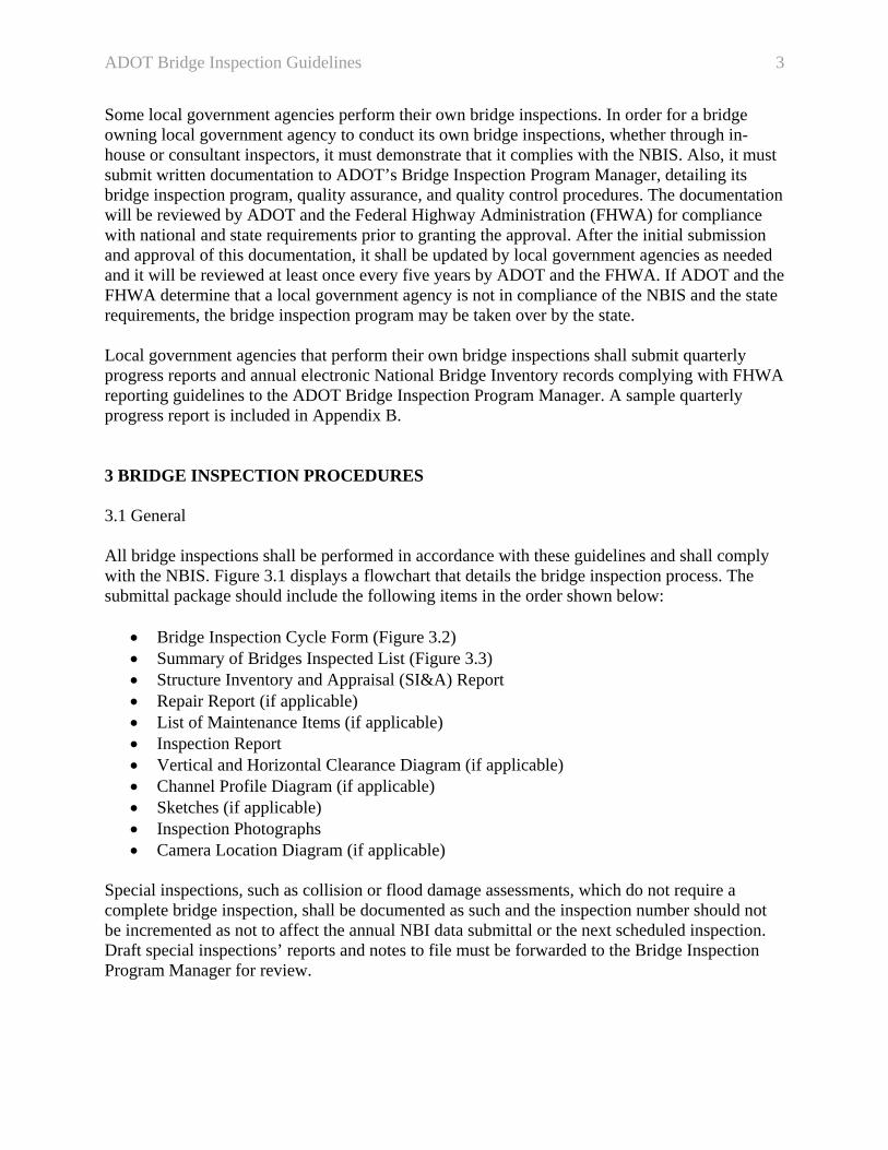
Some local government agencies perform their own bridge inspections. In order for a bridge owning local government agency to conduct its own bridge inspections, whether through in-house or consultant inspectors, it must demonstrate that it complies with the NBIS. Also, it must submit written documentation to ADOT’s Bridge Inspection Program Manager, detailing its bridge inspection program, quality assurance, and quality control procedures. The documentation will be reviewed by ADOT and the Federal Highway Administration (FHWA) for compliance with national and state requirements prior to granting the approval. After the initial submission and approval of this documentation, it shall be updated by local government agencies as needed and it will be reviewed at least once every five years by ADOT and the FHWA. If ADOT and the FHWA determine that a local government agency is not in compliance of the NBIS and the state requirements, the bridge inspection program may be taken over by the state. Local government agencies that perform their own bridge inspections shall submit quarterly progress reports and annual electronic National Bridge Inventory records complying with FHWA reporting guidelines to the ADOT Bridge Inspection Program Manager. A sample quarterly progress report is included in Appendix B. 3 BRIDGE INSPECTION PROCEDURES 3.1 General All bridge inspections shall be performed in accordance with these guidelines and shall comply with the NBIS. Figure 3.1 displays a flowchart that details the bridge inspection process. The submittal package should include the following items in the order shown below:
• Bridge Inspection Cycle Form (Figure 3.2) • Summary of Bridges Inspected List (Figure 3.3) • Structure Inventory and Appraisal (SI&A) Report • Repair Report (if applicable) • List of Maintenance Items (if applicable) • Inspection Report • Vertical and Horizontal Clearance Diagram (if applicable) • Channel Profile Diagram (if applicable) • Sketches (if applicable) • Inspection Photographs • Camera Location Diagram (if applicable)
Special inspections, such as collision or flood damage assessments, which do not require a complete bridge inspection, shall be documented as such and the inspection number should not be incremented as not to affect the annual NBI data submittal or the next scheduled inspection. Draft special inspections’ reports and notes to file must be forwarded to the Bridge Inspection Program Manager for review.
ADOT Bridge Inspection Guidelines 4
Figure 3.1 – ADOT Bridge Inspection Flowchart
Prepare a list of bridges to be inspected
Generate a Bridge Inspection Cycle Form* (see Figure 3.2) and a Summary of Bridges
Inspected List* (see Figure 3.3)
Check-out the bridge records from ADOT’s Bridge Inspection Software
Review current bridge information
Perform field inspection
Prepare appropriate inspection reports
Check-in the bridge records into ADOT’s Bridge Inspection Software, then
Submit draft reports for review
Turn-in the Bridge Inspection Cycle Form*, the Summary of Bridges Inspected List*, and the
List of Maintenance Items (if applicable)
Finalize reports according to review comments (in case of disagreements, escalate to appropriate
level for resolution)
* Cycle Forms and Summary of Bridges Inspected Lists shall always be prepared by ADOT staff
ADOT Bridge Inspection Guidelines 5
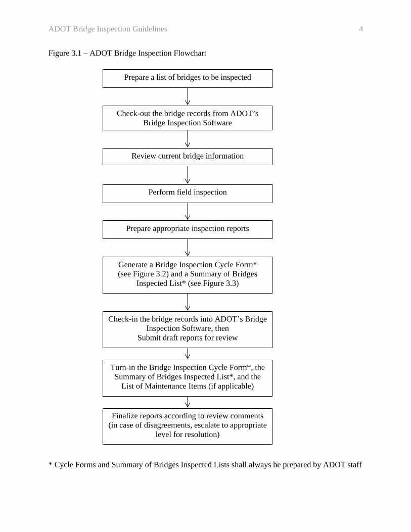
Figure 3.2 – Bridge Inspection Cycle Form
Notes: 1. Cycle Forms and Summary of Bridges Inspected Lists should list the same bridges.
2. Each Cycle Form should contain bridges owned by only one Agency. For State Bridges, Cycle Forms should be generated by Single Maintenance Organization Number and bridges should be listed in Remarks Section by ascending Milepost order. Local Agency bridges will be listed in Remarks Section in sequential order of bridge number. Cycle Forms will be created by in-house teams having responsibility over the region where the bridges are located. Generally, no more than 15 bridges should be listed on one Cycle Form (this also applies to Summary of Bridges Inspected List).

ADOT Bridge Inspection Guidelines 6
Figure 3.3 – Summary of Bridges Inspected List
Notes: 1. Place a check mark in the “Reviewed?” box if the structure is selected for review.
2. Place a check mark in “Copy to Signs” when a repair recommendation relates to traffic signs, such as vertical clearance, weight limit signs, or other signs attached to the bridge. 3. Place a check mark in “Copy to BHS” when a repair recommendation or maintenance item relates to scour, head cutting etc… 4. Place a check mark in “Copy to BMS Leader” if: a. An overall condition rating is being modified by two points or is 4 or less. b. A structure lost or gained a SD or FO classification. c. Change to inspection frequency (NBI item N91).
d. A structure is closed or replaced (retired). e. A scour critical structure without a POA in the bridge file. f. It is an initial inspection. g. A major repair is recommended.
5. Place a check mark in “Copy to BTS” when a load rating analysis is needed.

ADOT Bridge Inspection Guidelines 7
3.2 Bridge Inspection Planning
• Inspection personnel should contact ADOT District maintenance organizations or appropriate local government personnel prior to inspecting bridges that are located within the jurisdiction of these entities. Maintenance or local government personnel should be encouraged to accompany the bridge inspection team during the field inspections. They could provide valuable information about on-going maintenance issues, flooding history, previous repair projects, and planned future projects. Also, in the case of local government agencies, they may identify structures that need to be added to the NBI.
• When planning bridge inspections, websites that display information on traffic restrictions caused by construction must be consulted. Inspection personnel must coordinate bridge inspection activities in construction zones with resident engineers.
• When required, traffic control plans for bridge inspections should be prepared in consultation with ADOT District or local agency personnel. They must be submitted at least two weeks prior to the inspection and must be approved by the District or the local government agency that have jurisdiction over the bridge. The approved Traffic Control plans should be sent to BMS for recordkeeping.
• Bridge inspectors should gather any missing bridge documentation such as as-built drawings for existing and new structures and determine if any structure was rehabilitated or replaced and include project plans in the bridge file. The plan information on the inside cover of the inspection folder should be updated accordingly.
• Prior to inspecting bridges which carry or cross over railroad tracks, a permit may need to be obtained from the railroad company. In certain instances, ADOT has obtained a systemic permit from railroad companies to inspect those bridges. Bridge inspectors should check the availability of such permits. In general, when the bridge carries the railroad tracks, the railroad company would be the bridge owner (NBI item N22 = 27) and the state or the local agency will be responsible for its maintenance (NBI item N21 should be coded according to the road ownership). When the bridge spans over the railroad tracks, both ownership and maintenance responsibility belong to the state or the local agency and NBI items N21 and N22 should be coded accordingly.
• Inspection personnel should strive to schedule inspections of canal bridges during dry out periods.
• Jointly owned border bridges with California, City of Needles, and Nevada are inspected by Caltrans or NDOT under the terms of Intergovernmental Agreements between Arizona and these other entities. Inspection reports and data must be obtained and documented in Arizona’s bridge inventory.
• Structure numbers are assigned by the Bridge Inspection Program Manager to all NBI structures based on ownership. Whenever a structure ownership transfers from the state to a local government or vice versa, a new structure number must be assigned and the old number is retired. Transfer of structures’ ownership between local governments will not necessitate an assignment of a new structure number.
• Initial bridge inspections should be performed prior to opening the roadway to traffic. This would facilitate the condition assessment of all bridge elements and would enable accurate measurements of vertical and horizontal clearances under safe conditions.
ADOT Bridge Inspection Guidelines 8
• It is imperative that bridge inspection personnel, whether ADOT or consultant staff, comply with all of ADOT’s safety policies at all times including wearing hard hats, steel toed boots and safety vests.
3.3 Field Inspection Currently, ADOT requires that both the NBI condition rating and the element level rating be evaluated. It is the responsibility of the inspection personnel to ensure that values assigned through these two methods are not in conflict. For example, a deck condition rating of 4 (NBI Item N58) should not be utilized with a deck element condition state of 1. During field inspection, team members should adhere to the following:
• Remain within the limits of the right of way. • When specifying traffic directions on the state highway system, the highway’s cardinal
direction should always be used instead of the compass direction. Compass directions should be used when specifying all other directions and when inspecting local agency bridges.
• In the event of the discovery of a new structure that qualifies for the NBI, inspection personnel should perform an initial inspection of that structure while in the field. Afterwards, the BMS office technician should be informed of the existence of the unaccounted for structure. A new structure number will be assigned and a skeleton record will be created in the database. At that point, the inspection team shall update the database with the information gathered in the field and create all necessary inspection documents.
• When inspecting a structure with missing as-built plans, inspection personnel should prepare elevation, plan, and cross-section details in addition to obtaining all required information for conducting a load rating analysis.
• The inspector must alert the Bridge Inspection Program Manager whenever a bridge element has deteriorated or has been damaged to an extent where a new load rating must be performed. A review of the Load Rating Report could provide valuable information about critical bridge elements and locations. An increase in overlay thickness could also justify a new load rating.
• In the event that a scour plan of action (POA) does not reflect current conditions, the inspector must alert the Bridge Inspection Program Manager.
3.4 Bridge Inspection Documents Bridge inspection documents must be written using appropriate technical terminology. They should not contain abbreviated text. Inspectors’ personal notebooks may contain those; however, inspectors should refrain from using any abbreviation in all formal documents that are associated with the bridge inspection. Common acronyms may be used. The following bridge inspection documents are normally produced as a result of an inspection:
• Structure Inventory and Appraisal (SI&A) Report
ADOT Bridge Inspection Guidelines 9
• Repair Report (if applicable) • List of Maintenance Items (if applicable) • Inspection Report • Vertical and Horizontal Clearance Diagram (if applicable) • Channel Profile Diagram (if applicable) • Sketches (if applicable) • Inspection Photographs • Camera Location Diagram (if applicable)
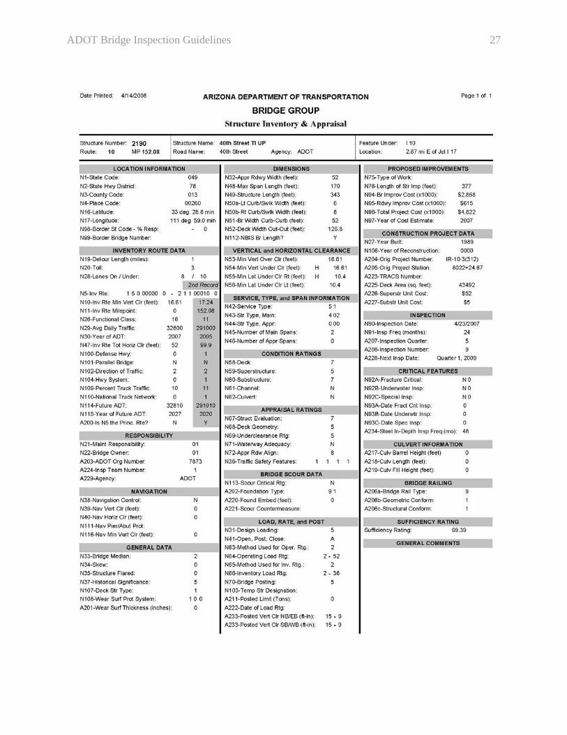
A description of each of the above documents follows. In addition, a sample of each of these documents is included in Appendix A. 3.4.1 Structure Inventory and Appraisal (SI&A) Report The SI&A document is a collection of bridge data that include a large portion of the fields which constitute the NBI. ADOT customized this NBIS required report by grouping like data together and adding Arizona specific items to it. 3.4.1.1 General
• When a dropdown list is provided within the inspection software, the user shall select the appropriate entry from the list. In the event that the list is missing an appropriate entry, the user shall notify the database administrator so that the list would be updated accordingly.
• NBI items N13a and N13b, LRS Inventory Route and Sub-route, are globally populated by the database administrator.
• When coding NBI item N28a, Lanes on, count and record lanes which carry actual traffic only. A temporarily closed lane, i.e., for construction purposes, shall be counted. Lanes that are not in use, including median lanes, shall not be counted.
• The inspection quarter field, Arizona item A207, shall not be altered! Next inspection due date, Arizona item A228, should be equal to current inspection date, NBI item N90, plus the inspection frequency, NBI item N91. However, if the calculated date would result in a future inspection date beyond the assigned inspection quarter, then the last day of the assigned quarter should be used for A228.
• Arizona item A235 must only be set to “Active” after the initial inspection has been reviewed and finalized.
• During the initial inspection of a structure that was replaced, Arizona item A300 must contain a reference to the number of the retired (replaced) structure. Also, prior to designating the replaced structure as “Retired” under Arizona item A235, item A300 must contain a reference to the new structure number. Note that once a structure is designated as “Retired”, A235 = R, the inspection software will prevent the user from making any updates to the database. Therefore, all updates and cross-references must be performed prior to setting A235 = R.

ADOT Bridge Inspection Guidelines 10
3.4.1.2 Data to Be Updated by Bridge Management Section Office Staff Only The following items, which are listed under the same headings that appear in the SI&A Report, should not be modified by inspection personnel without prior approval from the Bridge Inspection Program Manager:
• Location Information o NBI item N4, Place Code.
• Inventory Route Data o NBI item N26, Functional Route Classification.
• Responsibility o NBI item A203, ADOT Maintenance Org. Number.
• Load, Rate, and Post o NBI item N63, Method Used for Operating Rating. o NBI item N64, Operating Load Rating. o NBI item N65, Method Used for Inventory Rating. o NBI item N66, Inventory Load Rating. o NBI item N70, Bridge Posting (should be consistent with N41, Structure Open,
Posted, or Closed Traffic). o Arizona item A222, Date of Load Rating.
• Construction Project Data o Arizona item A225, Deck Area.
• Inspection o Arizona item A207, Inspection Quarter.
• Critical Features o NBI item N92A, Fracture Critical. o NBI item N92B, Underwater Inspection. o NBI item N92C, Special Inspection. o Arizona item A234, Steel In-Depth Inspection Frequency.
3.4.1.3 Common Data Entry Errors
• NBI item N5d, Inventory Route Number, is a 5-digit long numerical field and should start with leading zeros as needed. For example, use “00008” for I-8, “00010” for I-10, “00089” for 89A, “00101” for Loop 101, etc…
• NBI item N5e, Directional Suffix, shall not be left blank for any vehicular bridge. • NBI item N16, Latitude, is 5-digit long and does not contain decimal points, for example,
use “35273” for 35 degrees 27.3 minutes. • NBI item N17, Longitude, is 6-digit long and does not contain decimal points, for
example, use “114436” for 114 degrees 43.6 minutes. • When a previously recommended weight limit sign is missing, NBI item N41, Structure
Open, Posted, or Closed Traffic, shall be coded as “B”. A new repair recommendation to replace the missing sign should be created.
• NBI item N49, Structure Length, should be 20 ft or greater when NBI item N112, NBIS Bridge Length, is coded “Y”.

ADOT Bridge Inspection Guidelines 11
• Proposed Improvements items, NBI items N75, N76, N94, N95, N96 and N97, must be coded for any structure with a Sufficiency Rating of 80 or less; NBI item N97 shall indicate a date within 8 years from the current inspection year. Otherwise, the user must update this item.
• The year portion of NBI items N92 and N93, Critical Feature Inspection, must be coded as 4-digit (YYYY).
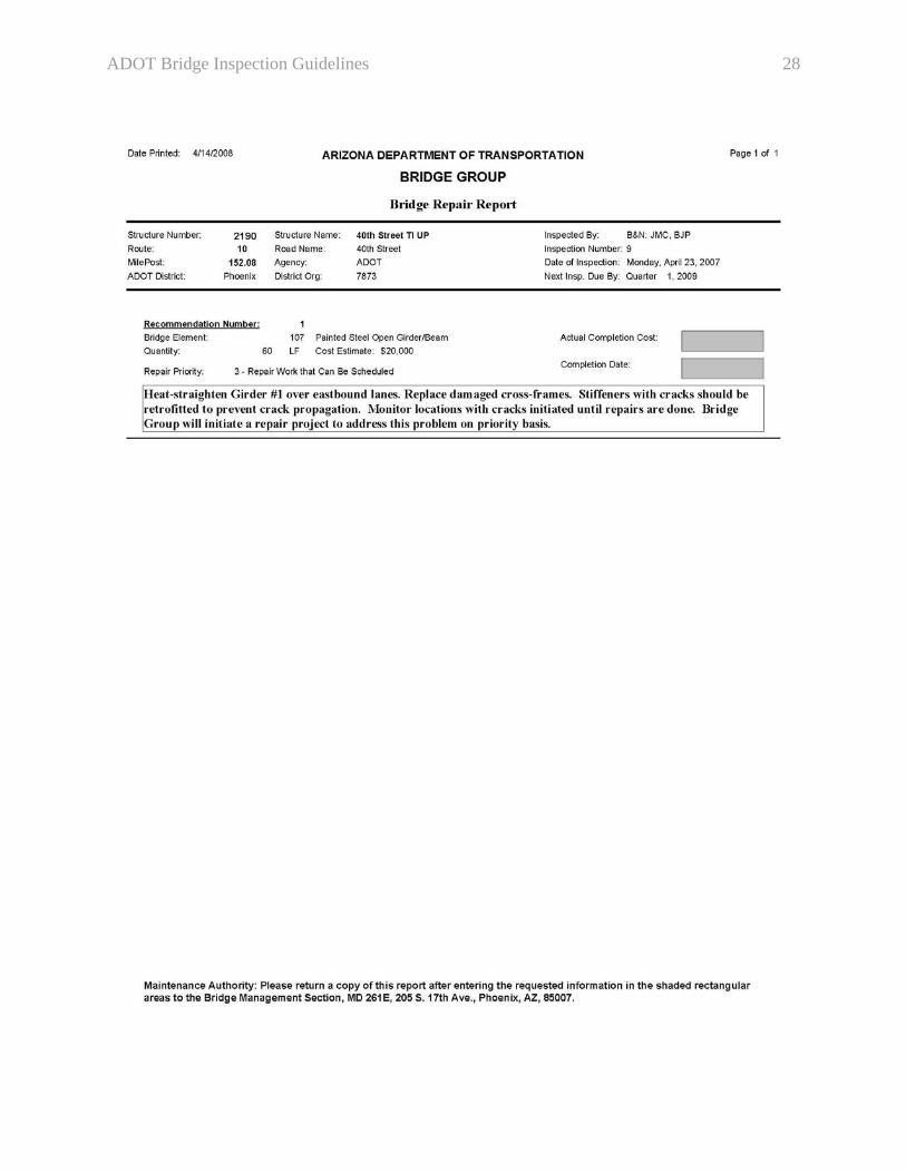
3.4.2 Repair Report / List of Maintenance Items Repair recommendations should only be issued for valid and practical items that need to be repaired. Inspection personnel should keep in mind that they are performing safety inspections of bridges and that repair recommendations that qualify under this criterion should be issued. Other observed maintenance related items should be noted in the various inspection notes’ fields provided throughout the inspection report sections. Therefore, a repair recommendation to patch a spall that does not affect the structural integrity of a given bridge element should not be made. Likewise, a repair recommendation dealing with aesthetic treatment should not be made. Both of these examples should be noted as observations in the appropriate inspection notes’ sections of the inspection report. A repair recommendation should not be created for the following maintenance items:
• Protruding joint angles* • Drainage grates, manhole and junction box covers* • Tree branches, vegetation, or other obstruction protruding over bridge decks* • Exposed wires, cables, etc…* • Approach slab settlements • Potholes in roadway approach or on bridge decks • Joints between approach roadway and approach slabs • Missing joint seals • Damage to chain link and pedestrian fences • Minor concrete spalls on bridge elements • Damage to roadway drainage appurtenances • Clogged drains • Damage to roadway approach guardrail and end treatment • Minor damage to bridge railings • Cleaning debris around bearings • Lighting fixtures, utility lines or casings • Bird netting damage • Cleaning of channel debris, vegetation growth, sediments, etc… • Cleaning debris and sedimentation from culverts • Graffiti removal
* This item may require immediate maintenance personnel notification depending on field conditions
ADOT Bridge Inspection Guidelines 12
• Weed removal • Irrigation system repair • Minor erosion • Minor damage to bank protection elements such as rail-banks, gabions, etc…
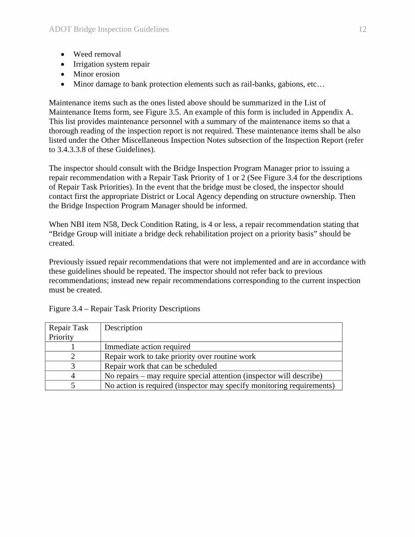
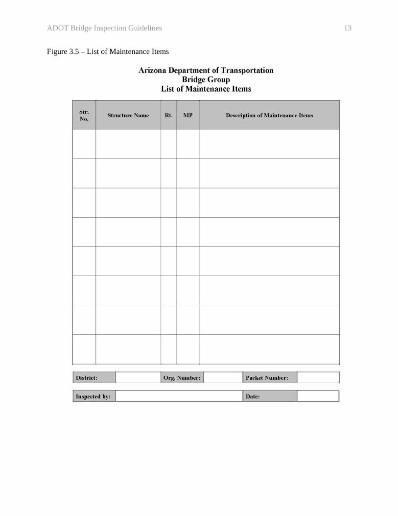
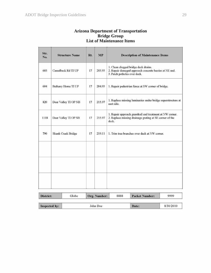
Maintenance items such as the ones listed above should be summarized in the List of Maintenance Items form, see Figure 3.5. An example of this form is included in Appendix A. This list provides maintenance personnel with a summary of the maintenance items so that a thorough reading of the inspection report is not required. These maintenance items shall be also listed under the Other Miscellaneous Inspection Notes subsection of the Inspection Report (refer to 3.4.3.3.8 of these Guidelines). The inspector should consult with the Bridge Inspection Program Manager prior to issuing a repair recommendation with a Repair Task Priority of 1 or 2 (See Figure 3.4 for the descriptions of Repair Task Priorities). In the event that the bridge must be closed, the inspector should contact first the appropriate District or Local Agency depending on structure ownership. Then the Bridge Inspection Program Manager should be informed. When NBI item N58, Deck Condition Rating, is 4 or less, a repair recommendation stating that “Bridge Group will initiate a bridge deck rehabilitation project on a priority basis” should be created. Previously issued repair recommendations that were not implemented and are in accordance with these guidelines should be repeated. The inspector should not refer back to previous recommendations; instead new repair recommendations corresponding to the current inspection must be created. Figure 3.4 – Repair Task Priority Descriptions Repair Task Priority
Description
1 Immediate action required 2 Repair work to take priority over routine work 3 Repair work that can be scheduled 4 No repairs – may require special attention (inspector will describe) 5 No action is required (inspector may specify monitoring requirements)
ADOT Bridge Inspection Guidelines 13
Figure 3.5 – List of Maintenance Items

ADOT Bridge Inspection Guidelines 14
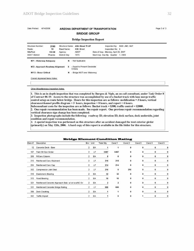
3.4.3 Inspection Report The bridge inspection report documents all of the observations that are made during the field inspection. Bridge inspection reports must be sealed and signed by a professional engineer licensed in civil or structural engineering by the Arizona Board of Technical Registration. Corrections should be implemented prior to sealing and signing reports. Inspection personnel should strive to maintain objectivity and factual reporting of field observations. Subjective reporting and editorializing of comments are not acceptable. 3.4.3.1 General
• Inspection notes should be provided for all bridge components. This includes situations where components are in good condition. For example and if appropriate, the inspector should remark that “overall superstructure is in good condition”.
• Element and sub-element descriptions should be always provided and not left blank. In some instances, consulting the as-built plans may be helpful. Comments or observations should be documented within the Notes sections and not within these descriptions.
• Condition ratings shall be assigned based on the overall condition of the bridge element and not on a localized area. Any one point increase or decrease in condition ratings should be documented as inspection notes. Element condition states must be updated accordingly to maintain consistency between the two rating methods.
• Inspection personnel should consult with the Bridge Inspection Program Manager whenever a condition rating is being modified by two points or more.
• The Bridge Inspection Program Manager must be notified in instances where an overall condition rating is 4 or less.
• When bridge elements are not visible, inspectors should maintain previously documented condition ratings unless actions were taken to improve the condition of the element since the last inspection. Those actions must be documented in the inspection report and bridge file. A note clarifying that the element is not visible or accessible should also be added. A common example is when a bridge deck is overlaid since the last inspection.
• Condition ratings of 9 should only be used when describing excellent element conditions for newly built structures.
• Appropriate justification is needed in the event that: o The sufficiency rating significantly changes; o The structure is no longer classified as structurally deficient or functionally
obsolete; or o The structure gains a structurally deficient or functionally obsolete classification.
• Piers and spans should be numbered sequentially in the direction of increasing stations. Note that the first substructure element is referred to as abutment number 1; therefore, span number 1 spans between abutment number 1 and pier number 1. Girders are numbered from left to right while looking towards increasing stations. This information should be consistent with as-built plans. The inspector should note that some existing bridge inspection documentation may not have followed the convention stated above. In those cases, bridge inspectors should follow the existing convention for numbering abutments, piers, spans and girders to
ADOT Bridge Inspection Guidelines 15
maintain consistency with past inspections. However, this should be documented in the report for future reference.
• NBI item N90, Inspection Date, shall be the date of the field inspection. In the event of a multiple day inspection, N90 should correspond to the last day of inspection.
3.4.3.2 Characterization of Concrete Deterioration Use the following terms, which are found in the FHWA Bridge Inspector’s Reference Manual, when describing crack width, scaling or spalling of concrete elements: Crack widths: Describing cracks should include length, width, location, and intensity (few, numerous, etc.) To maintain consistency, it is essential to document crack width in the inspection notes using the following criteria:
• Hairline – crack width < 1/16 inch • Narrow – crack width from 1/16 inch to 1/8 inch • Medium – crack width from 1/8 inch to 3/16 inch • Wide – crack width > 3/16 inch
Concrete scaling: Scaling is the condition of concrete with gradual and continuing loss of mortar and aggregate over an area due to the chemical breakdown of the cement bond. Scaling is classified under the following four categories:
• Light or minor scaling – loss of surface mortar up to 1/4 inch deep, with a surface exposure of coarse aggregates.
• Medium or moderate scaling – loss of surface mortar from 1/4 inch to 1 /2 inch deep, with mortar loss between the coarse aggregates.
• Heavy scaling – loss of mortar from 1/2 inch to 1 inch deep, with clearly exposed coarse aggregates.
• Severe scaling – loss of coarse aggregate particles, as well as surface mortar and the mortar surrounding the aggregates; depth of loss exceeds 1 inch; reinforcing steel is usually exposed.
Concrete spalling: A spall is a circular or oval depression in concrete caused by a separation of a portion of the concrete surface. Spalls are classified as follows:
• Small – not more than 1 inch deep or approximately 6 inches in diameter. • Large – more than 1 inch deep or greater than 6 inches in diameter.
ADOT Bridge Inspection Guidelines 16
3.4.3.3 Sections within the Bridge Inspection Report The various sections within the Bridge Inspection Report are discussed in the following subsections: 3.4.3.3.1 Deck The following provides additional guidance when documenting deck inspection:
• NBI item N58, Overall Deck Condition Rating, shall be the lowest value of the Top Deck / Wearing Surface and the Deck Undersurface ratings. Top of deck rating shall refer to the structural condition of the deck. The condition of asphalt or other type of overlays should not be considered in the rating. Also, N58 coding should not be influenced by the condition of sidewalks, bridge railings, or deck joints.
• For culvert structures (“NBI item N43b = 19”), the Overall Deck Condition Rating, NBI item N58, shall always be “N”.
• If present, Sidewalk / Median / Curb description should correspond to data entered in NBI item 33, Bridge Median, and NBI item N50, Curb or Sidewalk Width.
• NBI item N108, Wearing Surface / Protective System, Arizona item A201, Wearing Surface Thickness, and the Element Level Inspection item must be coded consistently. If applicable, inspection personnel should verify the measurement of the overlay thickness in the field.
• The condition of joints between approach slabs and roadway pavement should be documented under Deck Inspection Notes as approach roadway joints.
• Typical hairline shrinkage cracks (crack width < 1/16 inch) in concrete curbs and railings do not need to be reported.
• An Overall Deck Condition Rating of 4 or less should trigger a repair recommendation. 3.4.3.3.2 Superstructure The following provides additional guidance when documenting superstructure inspection:
• For concrete slab bridge types, Main Members rating shall match NBI item N58, Overall Deck Condition Rating.
• When secondary members or bearing devices are not visible, their ratings should be “N” (not applicable). Their description may be copied from the as-built plans and a notation of “not visible” should be added to it.
• During an in-depth inspection, and if fracture critical members are present, the inspector should note whether or not any non-destructive testing was performed. Fracture critical members should be identified and documented within Arizona item A301, Structure Maintenance Notes. Also, the bridge inspection folder should contain a sketch identifying these members. The inspector must notify the Bridge Inspection Program Manager in the event the sketch is missing from the folder.
• Secondary members rating should not affect the Overall Superstructure Condition Rating. • For routine inspections of steel structures, the inspector may add the following note when
appropriate: “Since this is a routine inspection, not all of the comments made in the
ADOT Bridge Inspection Guidelines 17
previous in-depth inspection could be verified. However, they are transferred to this inspection report so that, if needed, they may be verified and updated during the next in-depth inspection.”
• Presence of lead in the paint on steel superstructure elements should be documented under Paint System – Description.
• Overhead cable lines crossing over the structure should be documented under Utilities. This is in addition to any utility attached to the structure. If applicable, the coding of NBI items N10 and N53, Minimum Vertical Clearance items, must be in accordance with the existence of such overhead utilities.
3.4.3.3.3 Substructure For non-waterway bridges, if the abutment slopes are armored, they shall be evaluated as slope protection. For waterway bridges, armored slope protection shall be evaluated as bank protection and included under waterway section of the inspection report. 3.4.3.3.4 Waterway The following provides additional guidance when documenting the Waterway section of the inspection report:
• If scour around pier or abutment is discovered during the inspection, the inspector should notify Bridge Hydraulics Section staff by checking the “Copy to BHS” box on the Summary of Bridges Inspected List (see Figure 3.3). A repair recommendation should not be generated.
• Dumped riprap or other dumped material along channel banks which is not designed as bank protection relative to size and toe-down depth should be coded as “N” under Bank Protection. Additionally, it should be clarified under “Description” that this dumped material was not designed as bank protection.
• Comments relating to channel stability should reflect the comparison of historical measurements as documented on channel profile diagrams.
3.4.3.3.5 Roadway The following provides additional guidance when documenting the Roadway section of the inspection report:
• The condition of joints between approach slabs and roadway pavement should be documented under Deck Inspection Notes as approach roadway joints.
• Erosion caused by roadway drainage must be documented in this section. • Measured vertical under clearances must be shown on the Vertical and Horizontal
Clearance Diagram. The minimum vertical under clearances, in each driving direction, must be noted under “Roadway/Safety Inspection Notes”.
ADOT Bridge Inspection Guidelines 18
3.4.3.3.6 Appraisal Items
• If scour around pier or abutment is discovered during the inspection, the inspector should not change the coding of NBI item N113. Bridge Hydraulics Section staff should be notified by checking the “Copy to BHS” box on the Summary of Bridges Inspected List (see Figure 3.3). Bridge Hydraulics Section would determine whether the coding need to be changed and would prioritize any needed remedial action.
• For all scour critical structures (NBI item N113 = 3), the inspector should review the scour Plan of Action (POA). The Bridge Inspection Program Manager shall be notified immediately in the event that a copy of the POA is missing from the bridge file or the POA needs to be updated.
3.4.3.3.7 Culverts
• Overall Deck Condition Rating, NBI item N58, shall always be “N”. • NBI items N36a and N36b, Culvert Railings and Rail Transitions, should be set to “N”
unless the fill height is less than 2 feet. • Culverts’ structure length, NBI item N49, should be measured parallel to the roadway
centerline, regardless of the skew of the headwalls. The measurement should be made between the inside faces of the exterior walls.
• NBI items N50a, N50b, N51, and N52, should be set to “0” unless the fill height is less than 2 feet.
3.4.3.3.8 Other Miscellaneous Inspection Notes
• When applicable, the following items should be noted within this Section: o Initial inspection o In-depth inspection o Special equipment used during the inspection o Traffic control o Consultant firm name, contract and task order numbers
• The inspector shall note whether or not previous repair recommendations were implemented. The recommendations that were not implemented should be repeated if they were in accordance with current guidelines (see section 3.4.2).
• All maintenance items that are to be included in the List of Maintenance Items Report, see Figure 3.5, shall be listed under this subsection of the Inspection Report.
• The inspector shall list, on separate lines, the description of each of the photographs that are taken. The photograph description should be preceded by a sequential number corresponding to the number of the photograph as it was added to the inspection software. The file name may not be repeated in this section.
3.4.3.3.9 Bridge Element Condition States
• Element condition states must be consistent with NBI item condition ratings.

ADOT Bridge Inspection Guidelines 19
• Observed cracks on top of decks should be coded under Element Number 358, Deck Cracking. Whereas cracks on underside of decks or superstructure soffits should be coded under Element Number 359, Soffit of Concrete Decks and Slabs.
• For scour critical structures, an appropriate condition state of Element Number 361, Scour, should be selected.
• Element Number 362, Traffic Impact, should not be used to indicate damage to bridge railing.
3.4.4 Vertical and Horizontal Clearance Diagram The clearance diagram shall graphically document lateral and vertical clearances. Measurements entered in the database should be coded in feet including decimal points; for example, 16.5 would be the correct coding for a 16’-6” measurement. The following should be adhered to when preparing clearance diagrams:
• Vertical clearances shall be measured from items attached to the superstructure such as lights and signs if they result in lower vertical clearances. If measurements were copied from as-built plans, the inspector must document same with a note below the diagram.
• When updating previous measurements, and in the event those are different, the inspector should cross-out the existing value and write the updated value next to it.
• Depending on accessibility and the type of inspection that is being performed, the inspector may not be able to verify the previous measurements. In that event, this should be noted below the diagram.
• Vertical clearance signs are required if the minimum vertical clearance is equal or less than 16’-3”. A repair recommendation should be created stating that a vertical clearance sign is needed and specifying the clearance as the measurement minus 3”. The 3 inch is a buffer zone accounting for vehicle bounce.
• When a new vertical clearance measurement conflicts with an existing posted sign, the inspector should consult with the Bridge Inspection Program Manager prior to issuing a repair recommendation.
• The inspector should create a new Vertical and Horizontal Clearance Diagram whenever the existing diagram becomes difficult to read. If certain measurements cannot be taken due to inaccessibility or other reasons, previous values should be transposed to the new diagram and should be clearly labeled as such.
• Posting a vertical clearance sign, where two or more structures are located close to each others, is governed by the lowest vertical clearance measurements of each of the structures. In some cases, this may lead to a posting attached to the structure with a higher vertical clearance than the other(s). In this event, the inspector must clearly document the structure that controls the vertical clearance on all structures’ diagrams; also, address this fact in the Roadway Inspection Notes.
• When a vertical clearance sign is required for a structure that crosses over both direction of traffic, one of the two following cases shall apply:
o No raised median: posted signs in both direction of traffic should reflect the same minimum vertical clearance.

ADOT Bridge Inspection Guidelines 20
o Raised median: each direction of traffic may have a different vertical clearance sign.
• Lateral under-clearance should be measured from edge of travel lane to: o The face of an obstruction such as pier, abutment walls, traffic barrier, or face of
curb; for relatively flat ground. o The toe of slopes steeper than 1:3, regardless of whether the slope is going up or
down. • The inspector should be aware that widened structures may require new vertical and
horizontal clearance measurements. 3.4.5 Channel Profile Diagram This diagram shall graphically document the cross-section profile underneath the bridge. The diagram is not required for concrete lined channels. The following should be adhered to when preparing channel diagrams:
• The inspector should make every effort to draw up to five successive diagrams on the same sheet to allow for a better understanding of changes in the channel profile over time.
• Vertical measurements should be taken at intervals of quarter spans and should be from the lowest point of the superstructure to the ground elevation underneath. For spans shorter than 40 feet, the inspector may omit quarter and three-quarter point measurements. If measuring from the top of the deck, usually due to inaccessibility, the depth of the superstructure should be subtracted from the measured value. Typically, these measurements should be taken at the upstream or downstream side of the bridge and the corresponding location should be noted on the diagram. It is important to consistently take measurements on the same side of the bridge. If this cannot be accomplished, a new diagram sheet should be created.
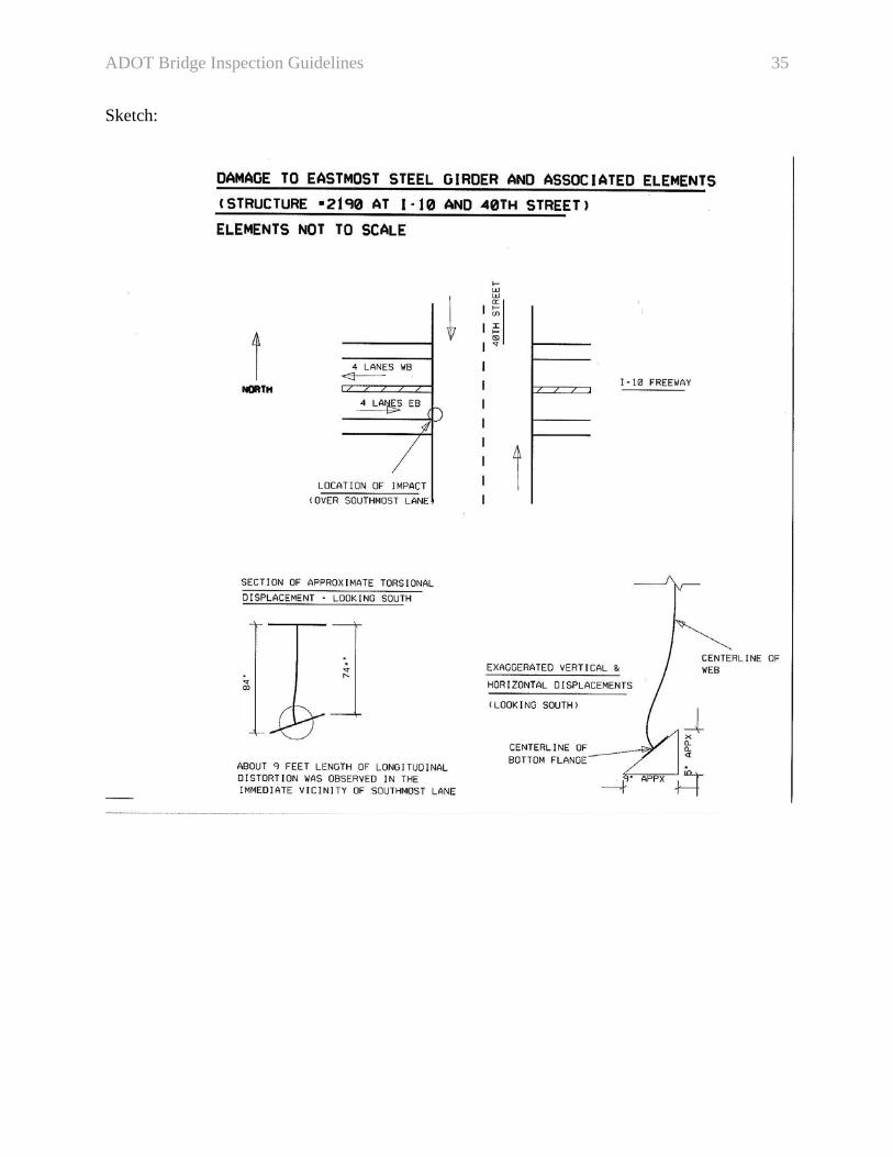
3.4.6 Sketches Sketches should be prepared whenever they are needed to better illustrate a condition encountered during the field inspection. A field condition that cannot be appropriately documented with photographs and written observations would require a sketch to be generated. An example of a needed sketch is when the inspector is trying to convey deteriorated areas of a bridge deck. A sketch could delineate and show dimensions of the affected areas. Another situation that may require a sketch is collision damage to a girder. Appendix A has an example of an inspection sketch.
ADOT Bridge Inspection Guidelines 21
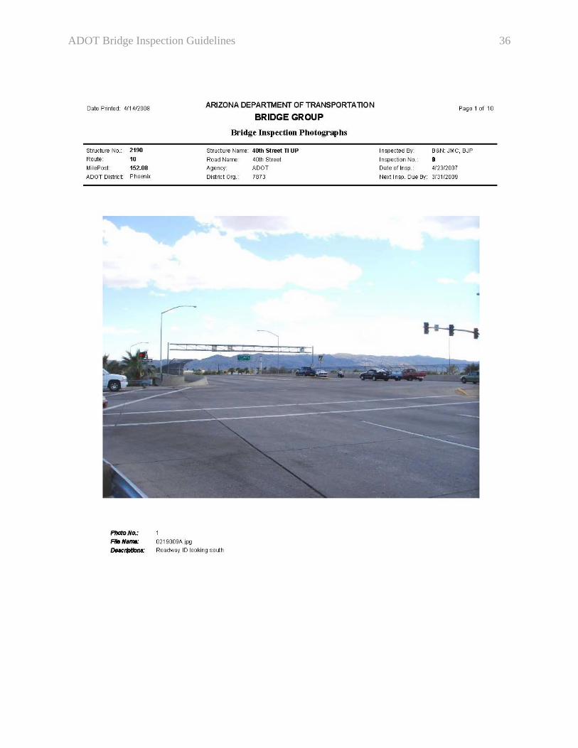
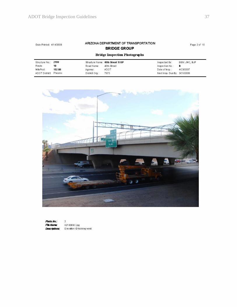
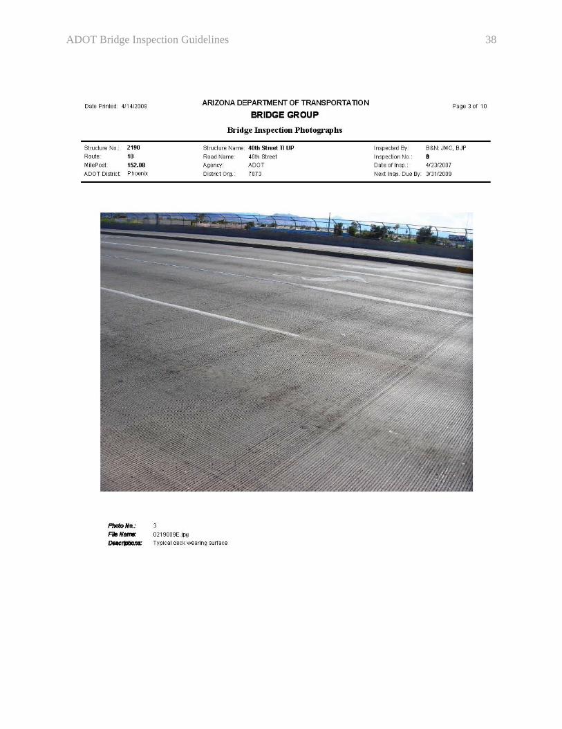
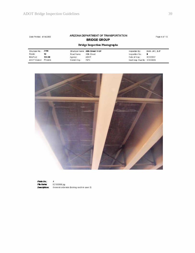
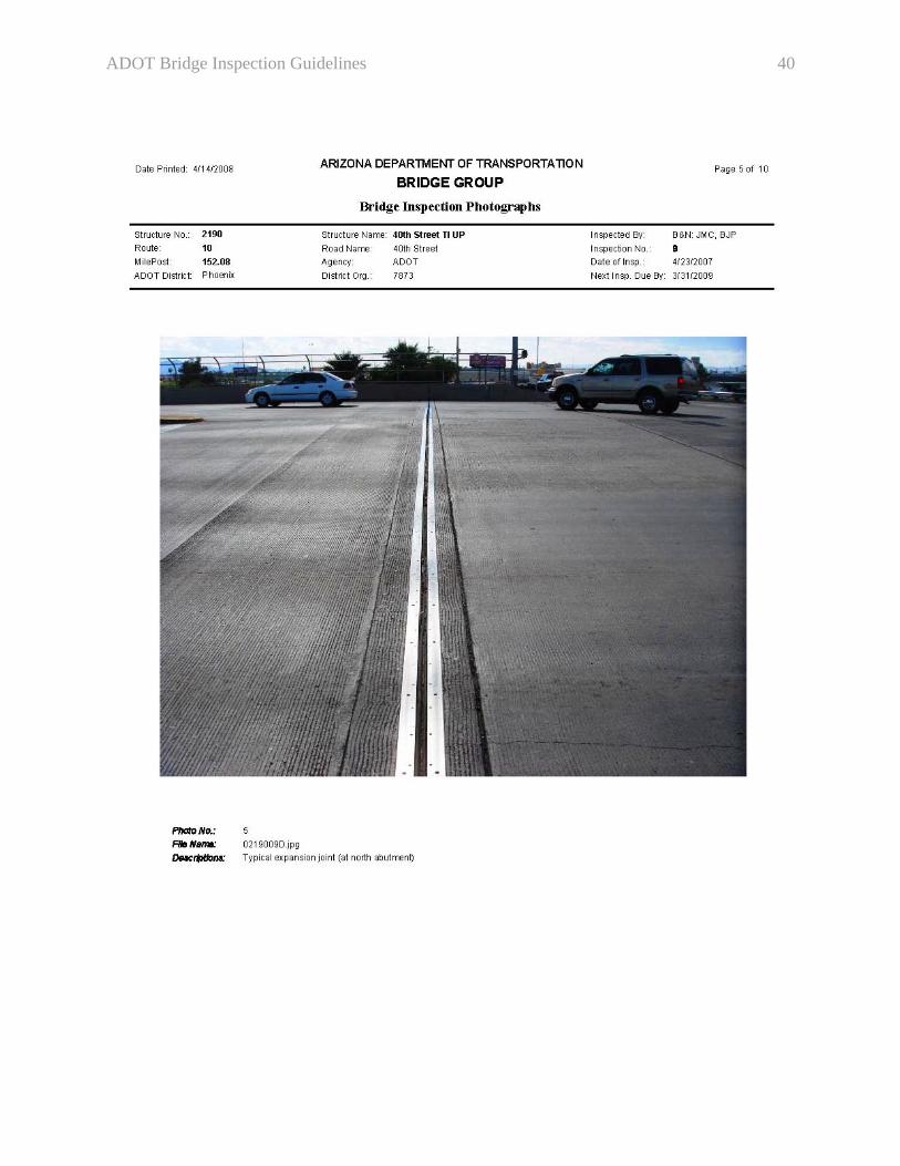
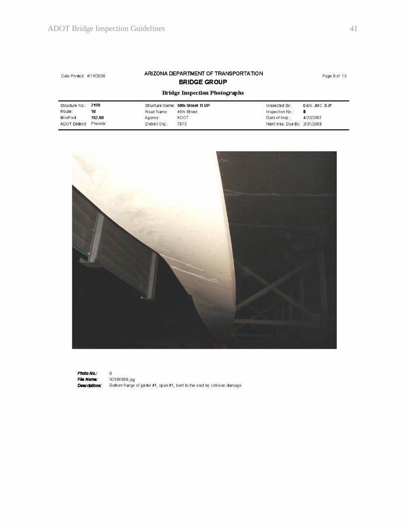
3.4.7 Inspection Photographs 3.4.7.1 General Photographs identifying the bridge roadway (Roadway ID), bridge elevation (Elevation ID), typical deck condition (top and bottom if possible), typical expansion or hinge joints if applicable, bridge elements requiring repair or maintenance, and any additional necessary features (such as weight limit signs or other signs) shall be obtained. These photographs are referenced below as the standard photographs. Previously recommended repairs that were completed since the last inspection should also be documented through photographs. Inspection personnel must not take an excessive number of photographs. For example, a single typical photograph of similar cracks would suffice. 3.4.7.2 Guidance for Taking Inspection Photographs
• Inspection personnel should strive to obtain the best possible photographs with utmost clarity and exposure.
• Photographs should not be included unless they are being referenced in inspection notes. The only exceptions are the following five standard photograph types: Roadway ID, Elevation ID, Deck Wearing Surface (including culverts with less than 2 feet of fill height), Structure Undersurface (soffit), and Deck Joint.
• When taking a photograph documenting the roadway or the elevation, it is useful to select an opposite direction to the previous inspection photograph.
• Roadway photographs should clearly show all lanes on the structure wearing surface. If there are two directions of travel, then the photograph should show both directions on the structure. For unusually wide structures, a separate photograph for each direction of travel may be taken instead and appropriately labeled.
• Inspectors should not refer to photographs taken during previous inspections. Instead, new photographs should be taken.
• Whenever possible, a photograph of an element requiring repair should be taken and referred to in the text of the repair recommendation.
• If the structure is posted for weight limit or other restrictions, include a photograph from both approaches showing said restrictions.
• Whenever a previously suggested repair is complete, a photograph must be taken to document said completion. In addition, the inspector should document with a statement in the inspection report.
• A list of all photographs that were taken during the inspection shall be included as a last item under “Other Miscellaneous Inspection Notes” of the Inspection Report. The list should be sequential and should contain the description of each photograph.
3.4.7.3 Digital Photograph Naming Convention
• All file names must contain 8 digits + “.” + “jpg” • The first 5 digits should indicate the structure number including leading zeros (type the
number “0” not the letter “O”).
ADOT Bridge Inspection Guidelines 22
• The 6th and 7th digit should indicate the inspection number. • The 8th and final digit should distinctly identify each photograph for that inspection by
using sequential letters of the alphabet (Type “A”, “B”, “C”, etc…)
Examples: 1. During the 22nd inspection of structure number 1280, five photos were taken. The five file names should be: 0128022A.jpg, 0128022B.jpg, 0128022C.jpg, 0128022D.jpg, and 0128022E.jpg. 2. During the 4th inspection of structure number 25, three photos were taken. The three file names should be: 0002504A.jpg, 0002504B.jpg, and 0002504C.jpg.
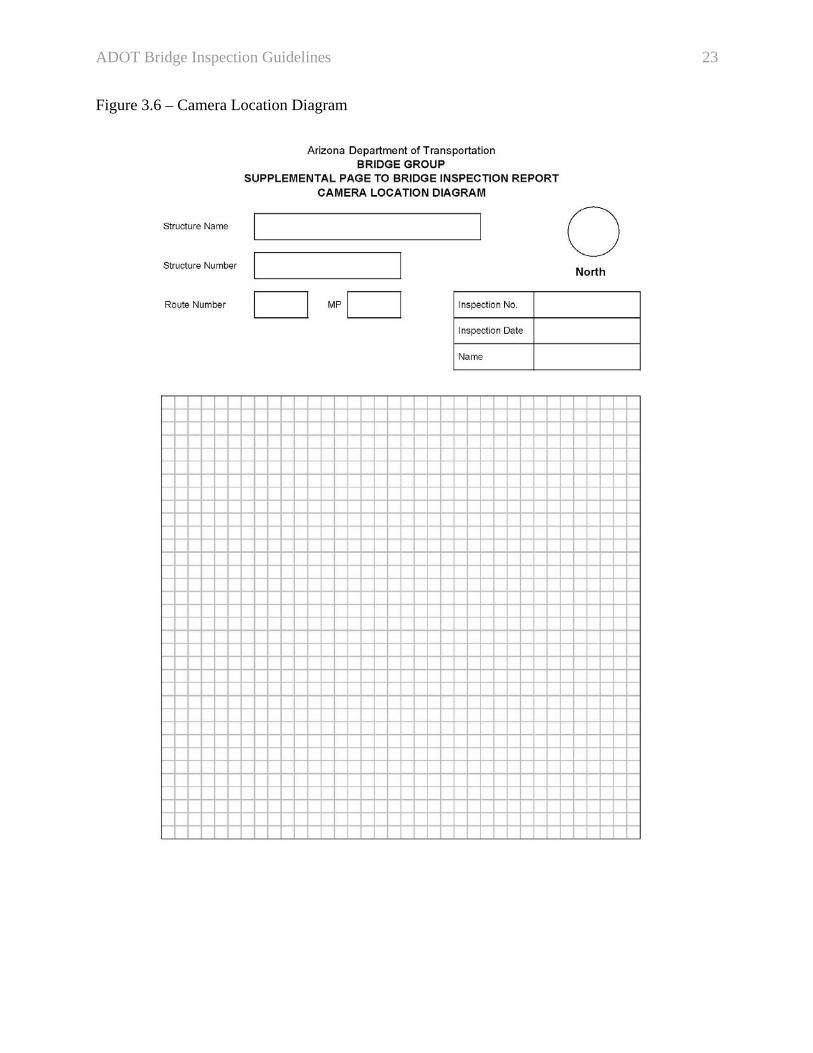
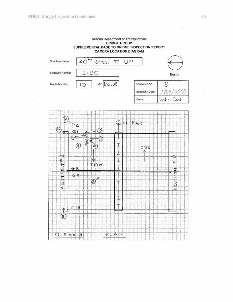
3.4.8 Camera Location Diagram A Camera Location Diagram, see Figure 3.6, is required to better orient the reader and reduce confusion when interpreting the inspection photographs. The inspector should decide if this diagram is needed. The diagram is not required if only standard bridge photographs are taken during the inspection. Appendix A shows an example of the Camera Location Diagram, a plan view of the bridge should be drawn with encircled photo numbers denoting the numbering sequence that was documented in the inspection report. The photo numbers should be written within the circle.
ADOT Bridge Inspection Guidelines 23
Figure 3.6 – Camera Location Diagram

ADOT Bridge Inspection Guidelines 24
4 BRIDGE INSPECTION LIFECYCLE When planning an inspection, inspection teams shall assemble bridges into packets. Bridge records are checked-out based on these packets. The lifecycle of a packet consists of the following milestones:
• Field inspection, report writing and submittal to the Bridge Management Section (BMS) review team (6 weeks)
• Inspection review by BMS (4 weeks) • Comment reconciliation and final submittal by inspection team (2 weeks)
The completion of the field inspection of the first bridge in a packet marks the beginning of the 12-week lifecycle of a bridge inspection packet. This lifecycle procedure applies to all inspections, whether performed by in-house staff or consultants, and shall be observed unless an exemption is granted by the Bridge Inspection Program Manager. 5 CRITICAL FINDINGS A critical finding is an observed condition that, if not promptly corrected, could result in the partial or total failure of the bridge. The Bridge Inspection Program Manager must be immediately alerted of any critical findings. The FHWA should be informed of those as well and their resolutions. The inspector should consult with the Bridge Inspection Program Manager prior to issuing a critical repair recommendation. Critical repair recommendations are equivalent to Repair Task Priority of 1 (Refer to Figure 3.4). In the event that the bridge must be closed, the inspection team should first contact the appropriate District or Local Agency depending on structure ownership. Then the Bridge Inspection Program Manager should be informed. 6 QUALITY ASSURANCE AND CONTROL Independent office review of bridge inspection documents will be performed to enhance quality assurance. Review engineers must select at least 10% of each packet of bridges to be reviewed. All inspection packets shall be reviewed regardless of bridge ownership and whether ADOT personnel or consultants performed the inspections. The following are some of the criteria that shall be used when selecting inspections to be reviewed:
• Initial Bridge Inspections • Bridges designated as Structurally Deficient • Bridges with Fracture Critical Members • Bridges with one or more condition rating that changed by 2 points or more • Change in sufficiency rating prefix (i.e., from blank to S or F, or vice versa) • Change in vertical or horizontal clearance that may affect NBI items • Inspections that produce repair recommendation
ADOT Bridge Inspection Guidelines 25
Bridge inspection personnel are reminded that assuring quality during their field inspection and throughout their documentation is their responsibility. The independent office review of bridge inspections is provided to maintain consistency throughout the state and shall not replace the due diligence that an inspector must exercise while performing and documenting each bridge inspection. Special attention should be accorded to pattern errors. Since the review may not entail every inspection report in a submitted packet, some errors may be repeated in non-reviewed reports. Therefore, the inspector must correct non-reviewed reports for similar types of comments. The quality of the bridge inspection program will be controlled through regularly scheduled training workshops, random office review of inspection documents, independent and concurrent field review of inspections, and independent field inspection conducted specifically for calibration purposes. In addition, the FHWA conducts an annual review of the bridge inspection program.
ADOT Bridge Inspection Guidelines 26
APPENDIX A – SAMPLE OF BRIDGE INSPECTION DOCUMENTS This appendix contains samples of the following bridge inspection documents:
• Structure Inventory and Appraisal (SI&A) Report • Repair Report • List of Maintenance Items • Inspection Report • Vertical and Horizontal Clearance Diagram • Channel Profile Diagram • Sketches • Inspection Photographs • Camera Location Diagram
These samples are provided to maintain consistency between inspection teams. They are not meant to restrict the individuality of each bridge inspection. They are intended to be used as guidance for a typical inspection of a typical Arizona bridge. Some of these documents were created for illustration purposes and are not based on actual inspections. Not all examples are related to the same bridge.
ADOT Bridge Inspection Guidelines 27
ADOT Bridge Inspection Guidelines 28
ADOT Bridge Inspection Guidelines 29

ADOT Bridge Inspection Guidelines 30

ADOT Bridge Inspection Guidelines 31
ADOT Bridge Inspection Guidelines 32

ADOT Bridge Inspection Guidelines 33

ADOT Bridge Inspection Guidelines 34
ADOT Bridge Inspection Guidelines 35
Sketch:
ADOT Bridge Inspection Guidelines 36
ADOT Bridge Inspection Guidelines 37
ADOT Bridge Inspection Guidelines 38
ADOT Bridge Inspection Guidelines 39
ADOT Bridge Inspection Guidelines 40
ADOT Bridge Inspection Guidelines 41
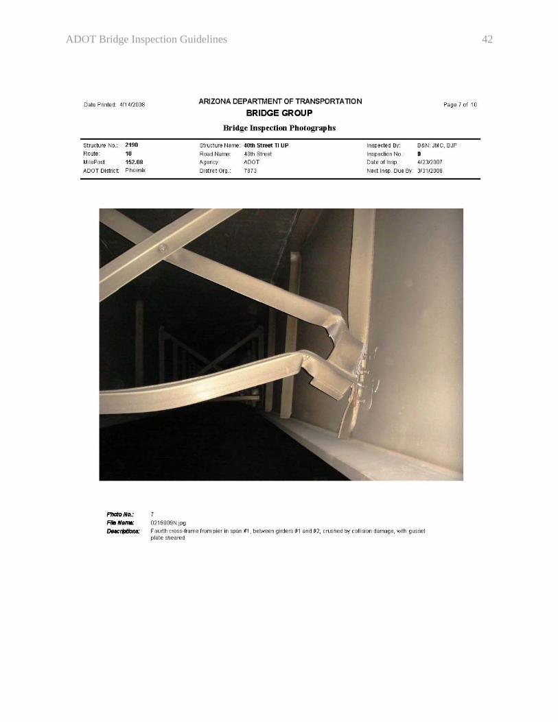
ADOT Bridge Inspection Guidelines 42
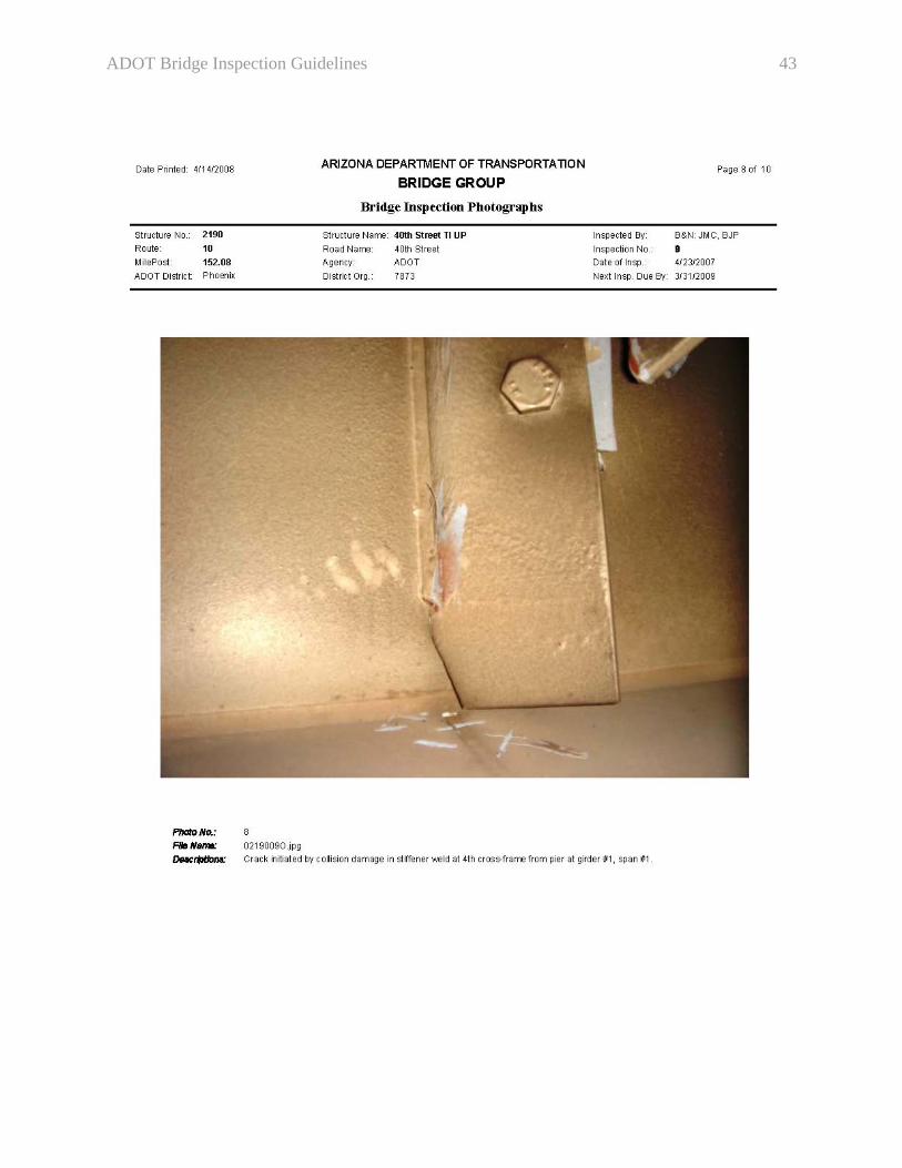
ADOT Bridge Inspection Guidelines 43
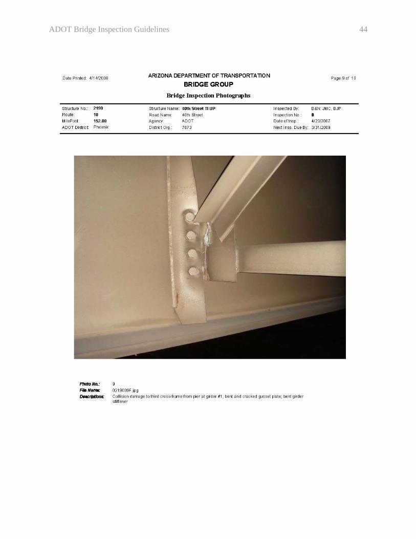
ADOT Bridge Inspection Guidelines 44
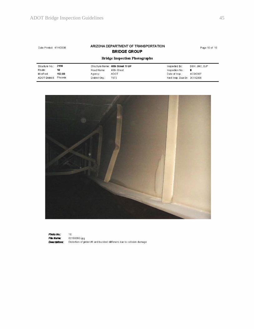
ADOT Bridge Inspection Guidelines 45
ADOT Bridge Inspection Guidelines 46

ADOT Bridge Inspection Guidelines 47
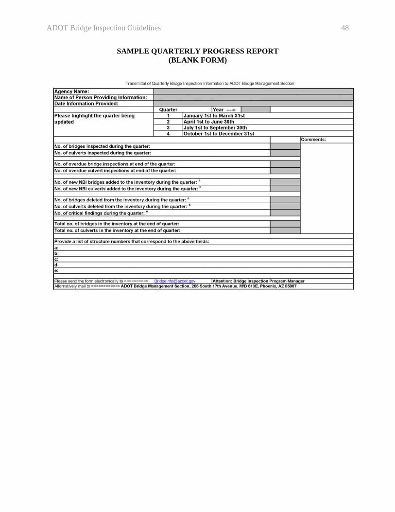
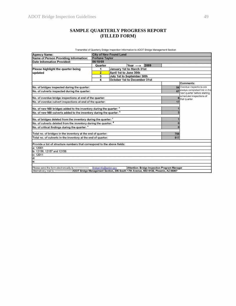
APPENDIX B – SAMPLE QUARTERLY PROGRESS REPORT This appendix contains two samples of the Quarterly Progress Report. The first sample is blank and the second one is filled.
ADOT Bridge Inspection Guidelines 48
SAMPLE QUARTERLY PROGRESS REPORT (BLANK FORM)
ADOT Bridge Inspection Guidelines 49
SAMPLE QUARTERLY PROGRESS REPORT (FILLED FORM)