Embed Size (px)
Citation preview
BRIDGE DESIGN SPECIFICATIONS bull MAY 2002
+
+ +
+
+ + +
+ + +
+
1052 For composite girders the ratio of the overall depth of girder (concrete slab plus steel girder) to the length of span preferably should not be less than 0045 for simple spans and 004 for continuous spans
1053 For trusses the ratio of depth to length of span preferably should not be less than 01
1054 Deleted
1055 The foregoing requirements as they relate to beam or girder bridges may be exceeded at the discretion of the designer
106 DEFLECTION
1061 The term ldquodeflectionrdquo as used herein shall be the deflection computed in accordance with the assumption made for loading when computing the stress in the member
1062 Members having simple or continuous spans preferably should be designed so that the ratio of the deflection to the length of the span due to service live load plus impact shall not exceed 1800 except on bridges in urban areas used in part by pedestrians whereon the ratio preferably shall not exceed 11000
1063 The ratio of the deflection to the cantilever arm length due to service live load plus impact preferably should be limited to 1300 except for the case including pedestrian use where the ratio preferably should be1375
1064 When spans have cross-bracing or diaphragms sufficient in depth or strength to ensure lateral distribution of loads the deflection may be computed for the standard H or HS loading considering all beams or stringers as acting together and having equal deflection
1065 The moment of inertia of the gross crossshysectional area shall be used for computing the deflections of beams and girders When the beam or girder is a part of a composite member the service live load may be considered as acting upon the composite section
1066 The gross area of each truss member shall be used in computing deflections of trusses If perforated plates are used the effective area shall be the net volume divided by the length from center to center of perforations
For consideration to be taken into account when exceeding these limitations reference is made to ldquoBulletin No19 Criteria for the Deflection of Steel Bridgesrdquo available from the American Iron and Steel Institute Washington DC
1067 The foregoing requirements as they relate to beam or girder bridges may be exceeded at the discretion of the designer
107 LIMITING LENGTHS OF MEMBERS
1071 For compression members the slenderness ratio KLr shall not exceed 120 for main members or those in which the major stresses result from dead or live load or both and shall not exceed 140 for secondary members or those whose primary purpose is to brace the structure against lateral or longitudinal force or to brace or reduce the unbraced length of other members main or secondary
1072 In determining the radius of gyrationr for the purpose of applying the limitations of the KLr ratio the area of any portion of a member may be neglected provided that the strength of the member as calculated without using the area thus neglected and the strength of the member as computed for the entire section with the KLr ratio applicable thereto both equal or exceed the computed + total force that the member must sustain
1073 The radius of gyration and the effective area of a member containing perforated cover plates shall be computed for a transverse section through the maximum width of perforation When perforations are staggered in opposite cover plates the cross-sectional area of the + member shall be considered the same as for a section having perforations in the same transverse plane
+ 1074 The unbraced length L shall be assumed as follows +
+For the compression chords of trusses the length between panel points laterally supported as indicated under Article 101612 for other members the length between panel point intersections or centers of braced points or centers of end connections
1075 For tension members except rods eyebars cables and plates the ratio of unbraced length to radius of gyration shall not exceed 200 for main members shall not exceed 240 for bracing members and shall not exceed 140 for main members subject to a reversal of stress
SECTION 10 STRUCTURAL STEEL 10-21
BRIDGE DESIGN SPECIFICATIONS bull MAY 2002
+ + +
+ +
+
+ +
+ +
+ + +
+ + + +
+
+
+ + + + + +
108 MINIMUM THICKNESS OF METAL
1081 The plate thickness of structural steel including bracing cross frames and all types of gusset plates shall be not less than516 inch The web thickness of rolled beams or channels shall be not less than 023 inches The thickness of closed ribs in orthotropic decks fillers and in railings shall be not less than 316 inch
1082 Where the metal will be exposed to marked corrosive influences it shall be increased in thickness or specially protected against corrosion
1083 It should be noted that there are other provisions in this section pertaining to thickness for fillers segments of compression members gusset plates etc As stated above fillers need not be516 inch minimum
1084 For compression members refer to ldquoTrussesrdquo (Article 1016)
1085 For flexural members refer to ldquoPlate Girdersrdquo (Article 1034)
1086 For stiffeners and outstanding legs of angles etc refer to relevant Articles 1010 1034 1037 1048 1051 and 1055
109 EFFECTIVE NET AREA FOR TENSION MEMBERS
1091 When a tension load is transmitted directly to each of the cross-sectional elements by fasteners or welds the effective net area Ae is equal to the net area An
1092 When a tension load is transmitted by bolts or rivets through some but not all of the cross-sectional elements of the member the effective net area Ae shall be calculated as
Ae = UA (10-1a)
where
A = area as defined below (in2) U = reduction coefficient
= 1 - (xL) pound 09 or as defined in (c) and (d) x = connection eccentricity (in) for rolled or builtshy
up shapes it is referred to the center of gravity of the material lying on either side of the centerline
of symmetry of the cross-section as shown in Fig 1092A
L = length of connection in the directions of loading (in)
Larger values of U are permitted to be used when justified by tests or other rational criteria
(a) When the tension load is transmitted only by bolts or rivets
A = An = net area of member (in2)
(b) When the tension load is transmitted only by longitudinal welds to other than a plate member or by longitudinal welds in combination with transverse welds
A = Ag = gross area of member (in2)
(c) When the tension load is transmitted only by transverse welds
A = area of directly connected elements (in2) U = 10
(d) When the tension load is transmitted to a plate by longitudinal welds along both edges at the end of the plate for Lw gt W
A = area of plate (in2)
for Lw Dagger 2W U = 10
for 2W gt Lw Dagger 15 W U = 087
for 15W gt Lw Dagger W U = 075
where
Lw = length of weld (in) W = plate width (distance between welds) (in)
1093 Deleted
1094 Deleted
+ + +
+ +
+ +
+
+ + +
+
+ +
+ +
+ + +
+
+ + + +
+
+ +
+
+
10-22 SECTION 10 STRUCTURAL STEEL
+
+
+
+
FIGURE 1092A Determination of x
1010 OUTSTANDING LEGS OF ANGLES
The widths of outstanding legs of angles in compresshysion (except where reinforced by plates) shall not exceed the following
In main members carrying axial compression load 12 times the thickness
In bracing and other secondary members 16 times the thickness
For other limitations see Article 10352
1011 EXPANSION AND CONTRACTION
In all bridges provisions shall be made in the design to resist thermal stresses induced or means shall be proshyvided for movement caused by temperature changes Provisions shall be made for changes in length of span resulting from live loads In spans more than 300 feet long allowance shall be made for expansion and contraction in the floor The expansion end shall be secured against lateral movement
BRIDGE DESIGN SPECIFICATIONS bull MAY 2002
1012 MEMBERS
10121 Flexural Members
Flexural members shall be designed using the elastic section modulus except when utilizing compact sections under Strength Design as specified in Articles 10481 105011 and 105021 In determining flexural strength the gross section shall be used except that if more than 15 percent of each flange area is removed that amount removed in excess of 15 percent shall be deducted from the gross area In no case shall the design tensile stress on the net section exceed 050Fu when using service load design method or 10 Fu when using strength design method where Fu equals the specified minimum tensile strength of the steel except that for M 270 Grades 100100W steels the design tensile stress on the net section shall not exceed 046 Fu when using the service load design method
10122 Compression Members
The strength of compression members connected by high-strength bolts and rivets shall be determined by the gross section
10123 Tension Members
The strength of tension members connected by bolts or rivets shall be determined by the gross section unless the net section area is less than 85 percent of the corresponding gross area in which case that amount removed in excess of 15 percent shall be deducted from the gross area In no case shall the design tensile stress on the net section exceed 050 Fu when using service load design method or 10 Fu when using strength design method where Fu
equals the specified minimum tensile strength of the steel except that for M 270 Grades 100100W steels the design tensile stress on the net section shall not exceed 046 Fu
when using the service load design method
1013 COVER PLATES
10131 The length of any cover plate added to a rolled beam shall be not less than (2d + 36) in where (d) is the depth of the beam (in)
+
+
+ + + + + + + +
+ +
+
+ + +
+
+ + + + + + + + + + + +
+ +
SECTION 10 STRUCTURAL STEEL 10-23
BRIDGE DESIGN SPECIFICATIONS bull MAY 2002
+
10132 Partial length welded cover plates shall not be used on flanges more than 08 inches thick for nonredundant load path structures subjected to repetitive loadings that produce tension or reversal of stress in the member
10133 The maximum thickness of a single cover plate on a flange shall not be greater than 2 times the thickness of the flange to which the cover plate is attached The total thickness of all cover plates should not be greater than 212 times the flange thickness
10134 Any partial length welded cover plate shall extend beyond the theoretical end by the terminal distance and it shall extend to a section where the stress range in the beam flange is equal to the allowable fatigue stress range for base metal adjacent to or connected by fillet welds The theoretical end of the cover plate when using service load design methods is the section at which the stress in the flange without that cover plate equals the allowable service load stress exclusive of fatigue considerations When using strength design methods the theoretical end of the cover plate is the section at which the flange strength without that cover plate equals the required strength for the design loads exclusive of fatigue requirements The terminal distance is two times the nominal cover plate width for cover plates not welded across their ends and 112 times for cover plates welded across their ends The width at ends of tapered cover plates shall be not less that 3 inches The weld connecting the cover plate to the flange in its terminal distance shall be continuous and of sufficient size to develop a total force of not less than the computed force in the cover plate at its theoretical end All welds connecting cover plates to beam flanges shall be continuous and shall not be smaller than the minimum size permitted by Article 102322
10135 Any partial length end-bolted cover plate shall extend beyond the theoretical end by the terminal distance equal to the length of the end-bolted portion and the cover plate shall extend to a section where the stress range in the beam flange is equal to the allowable fatigue stress range for base metal at ends of partial length welded cover plates with high-strength bolted slip-critical end connections (Table 1031B) Beams with end-bolted cover plates shall be fabricated in the following sequence drill holes clean faying surfaces install bolts weld The theoretical end of the end-bolted cover plate is determined in the same manner as that of a welded cover plate as specified in Article 1034 The bolts in the slip-critical connections of
the cover plate ends to the flange shall be of sufficient numbers to develop a total force of not less than the computed force in the cover plate at the theoretical end The slip resistance of the end-bolted connection shall be determined in accordance with Article 103232 for service load design and 105614 for load factor design The longitudinal welds connecting the cover plate to the beam flange shall be continuous and stop a distance equal to one bolt spacing before the first row of bolts in the endshybolted portion
1014 CAMBER
Girder should be cambered to compensate for dead load deflections and vertical curvature required by profile grade
1015 HEAT-CURVED ROLLED BEAMS AND WELDED PLATE GIRDERS
10151 Scope
This section pertains to rolled beans and welded Ishysection plate girders heat-curved to obtain a horizontal curvature Steels that are manufactured to a specified minimum yield strength greater than 50000 psi except for + Grade HPS 70W Steel shall not be heat-curved
10152 Minimum Radius of Curvature
101521 For heat-curved beams and girders the horizontal radius of curvature measured to the centerline of the girder web shall not be less than 150 feet and shall not be less than the larger of the values calculated (at any and all cross sections throughout the length of the girder) from the following two equations
440 b DR = +(10-1)Fy y tw
7500000 bR = (10-2) +Fyy
where
+Fy = specified minimum yield strength of the web (psi)
10-24 SECTION 10 STRUCTURAL STEEL
BRIDGE DESIGN SPECIFICATIONS bull MAY 2002
+ + + + + +
+
+
+ + + + + + + + + + + + + + + + +
y = ratio of the total cross-sectional area to the crossshysectional area of both flanges
b = widest flange width (in) D = clear distance between flanges (in) tw = web thickness (in) R = horizontal radius of curvature (in)
101522 In addition to the above requirements the radius shall not be less than 1000 feet when the flange thickness exceeds 3 inches or the flange width exceeds 30 inches
10153 Camber
To compensate for possible loss of camber of heatshycurved girders in service as residual stresses dissipate the amount of camber D (in) at any section along the length L of the girder shall be equal to
DDLD = (DM + DR ) (10-3)DM
002L2 Fy (1000 -R )D = Dagger 0R E Yo Ł 850 ł
where
DDL = camber at any point along the length L calcushylated by usual procedures to compensate for deflection due to dead loads or any other specishyfied loads (in)
DM = maximum value ofDDL within the lengthL (in) E = modulus of elasticity of steel (psi) Fy = specified minimum yield strength of girder flange
(psi) Yo = distance from the neutral axis to the extreme
outer fiber (in) (maximum distance for nonshysymmetrical sections)
R = radius of curvature (ft) L = span length for simple spans or for continuous
spans the distance between a simple end supshyport and the dead load contraflexure point or the distance between points of dead load contraflexure (in)
Camber loss between dead load contraflexure points adjashycent to piers is small and may be neglected
Note Part of the camber loss is attributable to construcshytion loads and will occur during construction of the bridge total camber loss will be complete after several months of in-service loads Therefore a portion of the camber increase (approximately 50 percent) should be included in the bridge profile Camber losses of this nature (but generally smaller in magnitude) are also known to occur in straight beams and girders
1016 TRUSSES
10161 General
101611 Component parts of individual truss memshybers may be connected by welds rivets or high-strength bolts
101612 Preference should be given to trusses with single intersection web systems Members shall be symmetrical about the central plane of the truss
101613 Trusses preferably shall have inclined end posts Laterally unsupported hip joints shall be avoided
101614 Main trusses shall be spaced a sufficient distance apart center to center to be secure against overturning by the design lateral forces +
101615 For the calculation of forces effective depths shall be assumed as follows
+
Riveted and bolted trusses distance between centers of gravity of the chords
Pin-connected trusses distance between centers of chord pins
10162 Truss Members
101621 Chord and web truss members shall usushyally be made in the following shapes
ldquoHrdquo sections made with two side segments (composed of angles or plates) with solid web perforated web or web of stay plates and lacing
SECTION 10 STRUCTURAL STEEL 10-25
BRIDGE DESIGN SPECIFICATIONS bull MAY 2002
+
+ +
Channel sections made with two angle segments with solid web perforated web or web of stay plates and lacing
Single Box sections made with side channels beams angles and plates or side segments of plates only connected top and bottom with perforated plates or stay plates and lacing
Single Box sections made with side channels beams angles and plates only connected at top with solid cover plates and at the bottom with perforated plates or stay plates and lacing
Double Box sections made with side channels beams angles and plates or side segments of plates only connected with a conventional solid web together with top and bottom perforated cover plates or stay plates and lacing
101622 If the shape of the truss permits comshypression chords shall be continuous
101623 In chords composed of angles in channel shaped members the vertical legs of the angles preferably shall extend downward
101624 If web members are subject to reversal of stress their end connections shall not be pinned Counters preferably shall be rigid Adjustable counters if used shall have open turnbuckles and in the design of these members an allowance of 10000 psi shall be made for initial stress Only one set of diagonals in any panel shall be adjustable Sleeve nuts and loop bars shall not be used
10163 Secondary Stresses
The design and details shall be such that secondary stresses will be as small as practicable Secondary stresses due to truss distortion or floor beam deflection usually need not be considered in any member the width of which measured parallel to the plane of distortion is less than one-tenth of its length If the secondary stress exceeds 4000 psi for tension members and 3000 psi for compresshysion members the excess shall be treated as a primary stress Stresses due to the flexural dead load moment of the member shall be considered as additional secondary stress
10164 Diaphragms
101641 There shall be diaphragms in the trusses at the end connections of floor beams
101642 The gusset plates engaging the pedestal pin at the end of the truss shall be connected by a diaphragm Similarly the webs of the pedestal shall if practicable be connected by a diaphragm
101643 There shall be a diaphragm between gusshyset plates engaging main members if the end tie plate is 4 feet or more from the point of intersection of the members
10165 Camber
The length of the truss members shall be such that the camber will be equal to or greater than the deflection produced by the dead load
10166 Working Lines and Gravity Axes
101661 Main members shall be proportioned so that their gravity axes will be as nearly as practicable in the center of the section
101662 In compression members of unsymmetrishycal section such as chord sections formed of side segshyments and a cover plate the gravity axis of the section shall coincide as nearly as practicable with the working line except that eccentricity may be introduced to counteract dead load bending In two-angle bottom chord or diagonal members the working line may be taken as the gage line nearest the back of the angle or at the center of gravity for welded trusses
10167 Portal and Sway Bracing
101671 Through truss spans shall have portal bracing preferably of the two-plane or box type rigidly connected to the end post and the top chord flanges and as deep as the clearance will allow If a single plane portal is used it shall be located preferably in the central transverse plane of the end posts with diaphragms beshytween the webs of the posts to provide for a distribution of the portal stresses The portal bracing shall be designed to take the full end reaction of the top chord lateral system and the end posts shall be designed to transfer this reaction to the truss bearings
10-26 SECTION 10 STRUCTURAL STEEL
BRIDGE DESIGN SPECIFICATIONS bull MAY 2002
101672 Through truss spans shall have sway bracing 5 feet or more deep at each intermediate panel point Top lateral struts shall be at least as deep as the top chord
101673 Deck truss spans shall have sway bracshying in the plane of the end posts and at all intermediate panel points This bracing shall extend the full depth of the trusses below the floor system The end sway bracing
+ shall be proportioned to carry the entire upper lateral load to the supports through the end posts of the truss
10168 Perforated Cover Plates
When perforated cover plates are used the following provisions shall govern their design
101681 The ratio of length in direction of stress to width of perforation shall not exceed two
101682 The clear distance between perforations in the direction of stress shall not be less than the distance between points of support
101683 The clear distance between the end pershyforation and the end of the cover plate shall not be less than 125 times the distance between points of support
101684 The point of support shall be the inner line of fasteners or fillet welds connecting the perforated plate to the flanges For plates butt welded to the flange edge of rolled segments the point of support may be taken as the weld whenever the ratio of the outstanding flange width to flange thickness of the rolled segment is less than seven Otherwise the point of support shall be the root of the flange of the rolled segment
101685 The periphery of the perforation at all points shall have a minimum radius of 112 inches
101686 For thickness of metal see Article 10352
10169 Stay Plates
101691 Where the open sides of compression members are not connected by perforated plates such members shall be provided with lacing bars and shall have stay plates as near each end as practicable Stay plates shall be provided at intermediate points where the lacing is interrupted In main members the length of the end stay
plates between end fasteners shall be not less than 114
times the distance between points of support and the length of intermediate stay plates not less than34 of that distance In lateral struts and other secondary members the overall length of end and intermediate stay plates shall be not less than 34 of the distance between points of support
101692 The point of support shall be the inner line of fasteners or fillet welds connecting the stay plates to the flanges For stay plates butt welded to the flange edge of rolled segment the point of support may be taken as the weld whenever the ratio of outstanding flange width to flange thickness or the rolled segment is less than seven Otherwise the point of support shall be the root of flange of rolled segment When stay plates are butt welded to rolled segments of a member the allowable stress in the member shall be determined in accordance with Article 103 Terminations of butt welds shall be ground smooth
101693 The separate segments of tension memshybers composed of shapes may be connected by perforated plates or by stay plates or end stay plates and lacing End stay plates shall have the same minimum length as specishyfied for end stay plates on main compression members and intermediate stay plates shall have a minimum length of 34 o f that specified for intermediate stay plates on main compression members The clear distance between stay plates on tension members shall not exceed 3 feet
101694 The thickness of stay plates shall be not less than150 of the distance between points of support for main members and 160 of that distance for bracing memshybers Stay plates shall be connected by not less than three fasteners on each side and in members having lacing bars the last fastener in the stay plates preferably shall also pass through the end of the adjacent bar
101610 Lacing Bars
When lacing bars are used the following provisions shall govern their design
1016101 Lacing bars of compression members shall be so spaced that the slenderness ratio of the portion of the flange included between the lacing bar connections will be not more than 40 or more than23 of the slenderness ratio of the member
+
+ + + + +
+ + +
+
SECTION 10 STRUCTURAL STEEL 10-27
BRIDGE DESIGN SPECIFICATIONS bull MAY 2002
1016102 The section of the lacing bars shall be determined by the formula for axial compression in which L is taken as the distance along the bar between its connections to the main segments for single lacing and as 70 percent of that distance for double lacing
1016103 If the distance across the member beshytween fastener lines in the flanges is more than 15 inches and a bar with a single fastener in the connection is used the lacing shall be double and fastened at the intersecshytions
1016104 The angle between the lacing bars and the axis of the member shall be approximately 45 degrees for double lacing and 60 degrees for single lacing
1016105 Lacing bars may be shapes or flat bars For main members the minimum thickness of flat bars shall be 140 of the distance along the bar between its connecshytions for single lacing and 160 for double lacing For bracing members the limits shall be 150 for single lacing and 175 for double lacing
1016106 The diameter of fasteners in lacing bars shall not exceed one-third the width of the bar There shall be at least two fasteners in each end of lacing bars connected to flanges more than 5 inches in width
101611 Gusset Plates
1016111 Gusset or connection plates preferably shall be used for connecting main members except when the members are pin-connected The fasteners connecting each member shall be symmetrical with the axis of the member so far as practicable and the full development of the elements of the member shall be given consideration The gusset plates shall be designed to resist shear axial force and bending moments acting on the weakest or critical section
1016112 Re-entrant cuts except curves made for appearance shall be avoided as far as practicable
1016113 If the length of unsupported edge of a gusset plate exceeds the value of the expression 11000 Fy times its thickness the edge shall be stiffshyened
expression 11000 yF for the following grades of steel
Fy (psi) 11000 yF
36000 58 50000 49 70000 42 90000 37 100000 35
1016114 Listed below are the values of the
101612 Half-Through Truss Spans
1016121 The vertical truss members and the floor beams and their connections in half-through truss spans shall be proportioned to resist a lateral force of not less than 300 pounds per linear foot applied at the top chord panel points of each truss
1016122 The compression chord shall be deshysigned as a compression member with elastic lateral supports at the panel points The strength of the compresshysion chord so determined shall exceed the maximum force from dead load live load and impact in any panel of the compression chord by not less than 50 percent
101613 Fastener Pitch in Ends of Compression Members
In the ends of compression members the pitch of fasteners connecting the component parts of the member shall not exceed four times the diameter of the fastener for a length equal to 112 times the maximum width of the member Beyond this point the pitch shall be increased gradually for a length equal to 112 times the maximum width of the member until the maximum pitch is reached
101614 Net Section of Riveted or High-Strength Bolted Tension Members
1016141 The net section of a riveted or highshystrength bolted tension member is the sum of the net sections of its component parts The net section of a part is the product of the thickness of the part multiplied by its least net width
For a discussion of columns with elastic lateral supports refer to Timoshenko amp Gere ldquoTheory of Elastic Stabilityrdquo McGraw-Hill Book Co Second Edition P70
+ + + + + + +
+ + +
+
10-28 SECTION 10 STRUCTURAL STEEL
BRIDGE DESIGN SPECIFICATIONS bull MAY 2002
1016142 The net width for any chain of holes extending progressively across the part shall be obtained by deducting from the gross width the sum of the diamshyeters of all the holes in the chain and adding for each gage space in the chain the quantity
2s+ (10-4)4g
where
+ s = pitch of any two successive holes in the chain + (in) + g = gage of the same holes (in)
The net section of the part is obtained from the chain that gives the least net width
1016143 For angles the gross width shall be the sum of the widths of the legs less the thickness The gage for holes in opposite legs shall be the sum of gages from back of angle less the thickness
1016144 At a splice the total force in the member+ + being spliced is transferred by fasteners to the splice
material
1016145 When determining the stress on any least net width of either splice material or member being spliced
+
+
the amount of the force previously transferred by fastenshyers adjacent to the section being investigated shall be
+ considered in determining the stress on the net section
1016146 The diameter of the hole shall be taken as 18 inch greater than the nominal diameter of the rivet or high-strength bolt unless larger holes are permitted in accordance with Article 1024
1017 BENTS AND TOWERS
10171 General
Bents preferably shall be composed of two supporting columns and the bents usually shall be united in pairs to form towers The design of members for bents and towers is governed by applicable articles
10172 Single Bents
Single bents shall have hinged ends or else shall be designed to resist bending
10173 Batter
Bents preferably shall have a sufficient spread at the base to prevent uplift under the design lateral loadings In general the width of a bent at its base shall be not less than one-third of its height
10174 Bracing
101741 Towers shall be braced both transversely and longitudinally with stiff members having either welded high-strength bolted or riveted connections The sections of members of longitudinal bracing in each panel shall not be less than those of the members in corresponding panels of the transverse bracing
101742 The bracing of long columns shall be designed to fix the column about both axes at or near the same point
101743 Horizontal diagonal bracing shall be placed in all towers having more than two vertical panels at alternate intermediate panel points
10175 Bottom Struts
The bottom struts of towers shall be strong enough to slide the movable shoes with the structure unloaded the coefficient of friction being assumed at 025 Provision for expansion of the tower bracing shall be made in the column bearings
1018 SPLICES
10181 General
101811 Design Strength
Splices may be made by rivets by high-strength bolts or by the use of welding In general splices whether in tension compression bending or shear shall be deshysigned in the cases of the service load design or the strength design methods for a capacity based on not less than 100 percent of the allowable design strength in the
+
+ + + + + +
SECTION 10 STRUCTURAL STEEL 10-29
BRIDGE DESIGN SPECIFICATIONS bull MAY 2002
+ member taking into account the bolt holes Bolted and + riveted splices in flexural members shall satisfy the requireshy+ ments of Article 10182 Bolted and riveted splices in + compression members shall satisfy the requirements of + Article 10183 Bolted and riveted splices in tension memshy+ bers shall satisfy the requirements of Article 10184 + Bolted and riveted splices in tension members shall also + satisfy the requirements of Article 10194 Welded splices + shall satisfy the requirements of Article 10185 Where a + section changes at a splice the small section is to be used + to satisfy the above splice requirements
101812 Fillers
1018121 For fillers 14 inch and thicker in bolted or riveted axially loaded connections including girder flange splices additional fasteners shall be required to distribute the total stress in the member uniformly over the combined section of the member and the filler The filler shall either
+ be extended beyond the splice material and secured by + additional fasteners or as an alternate to extending the + filler an equivalent number of fasteners may be included + in the connection Fillers 14 inch and thicker need not be + extended and developed provided that the design shear + strength of the fasteners specified in Article 1056132 in
the case of the strength design method and in the Tables 10323A and 10323B in the case of the service load design method is reduced by the following factor R
R=[(1+g)(1+2g)] (10-4a)
where g=Af Ap
+ Af = sum of the area of the fillers on the top and + bottom of the connected plate (in2) + +
Ap = smaller of either the connected plate area or the sum of the splice plate areas on the top and
+ bottom of the connected plate (in2)
+ The design slip force specified in Article 1056132 in + the case of the strength design method and in Article
1032321 in the case of the service load design method for slip-critical connections shall not be adjusted for the effect of the fillers Fillers 14 inch or more in thickness shall consist of not more than two plates unless special permisshysion is given by the Engineer
1018122 For bolted web splices with thickness differences of 116 inch or less no filler plates are required
1018123 Fillers for welded splices shall conform to the requirements of the AISIAASHTOAWS D15 Bridge Welding Code
101813 Design Force for Flange Splice Plates
For a flange splice with inner and outer splice plates the flange design force may be assumed to be divided equally to the inner and outer plates and their connections when the areas of the inner and outer plates do not differ by more than 10 percent When the areas of the inner and outer plates differ by more than 10 percent the design force in each splice plate and its connection shall be determined by multiplying the flange design force by the ratio of the area of the splice plate under consideration to the total area of the inner and outer splice plates For this case the shear strength of the connection shall be checked for the maximum calculated splice plate force acting on a single shear plane The slip resistance of high-strength bolted connections for a flange splice with inner and outer splice plates shall always be checked for the flange design force divided equally to the two slip planes
101814 Truss Chords and Columns
Splices in truss chords and columns shall be located as near to the panel points as practicable and usually on the side where smaller stress occurs The arrangement of plates angles or other splice elements shall be such as to make proper provision for the stresses both axial and bending in the component parts of the member spliced
10182 Flexural Member
101821 General
1018211 Splices shall preferably be made at or near points of dead load contraflexure in continuous spans and at points of the section change
1018212 In both flange and web splices there shall be not less than two rows of bolts on each side of the joint
1018213 Oversize or slotted holes shall not be used in either the member or the splice plates at the bolted splices
1018214 In both flange and web splices highshystrength bolted connections shall be proportioned to prevent slip during erection of the steel and during the casting or placing of the deck
+ + +
10-30 SECTION 10 STRUCTURAL STEEL
BRIDGE DESIGN SPECIFICATIONS bull MAY 2002
+
+ + +
+ +
+
+
+ + + + + + + +
+ +
+ +
+
+ + + + +
+
1018215 Deleted
1018216 Flange and web splices in areas of stress reversal shall be checked for both positive and negative flexure
1018217 Riveted and bolted flange angle splices shall include two angles one on each side of the flexural member
101822 Flange Splices
1018221 For checking the strength of flange splices an effective area A shall be used for the flanges and forethe individual splice plates as follows
For flanges and their splice plates subject to tension
Ae= wnt + b Ag pound Ag (10-4b)
where
Wn = least net width of the flange or splice plate computed as specified in Article101614 (in)
t = flange or splice plate thickness (in) Ag = gross area of the flange or splice plate (in2) b = 00 for M 270 Grade 100100W steels or when
holes exceed 1 14 inch in diameter = 015 for all other steels and when holes are less
than or equal to 1 14 inch in diameter
The diameter of the holes shall be taken as specified in Article 1016146
For the flanges and their splice plates subject to compression
Ae = Ag (10-4c)
1018222 In the case of the strength design method the splice plates shall be proportioned for a design force P equal to a design stressF times the smaller effectivecu cuarea A on either side of the splice F is defined ase cufollows
Fcu =a Fyf (10-4d)
where a = 10 except that a lower value equal to (MuMy) may
be used for flanges in compression at sections where Mu is less than My
Mu = design bending strength of the section in posishytive or negative flexure at the point of splice whichever causes the maximum compressive stress due to the factored loads at the mid-thickshyness of the flange under consideration (lb-in)
My = moment capacity at first yield for the section at the point of splice used to compute Mu (lb-in) For composite sectionsMy shall be calculated in accordance with Article1050(c) For hybrid secshytions My shall be computed in accordance with Article 1053
Fyf = specified minimum yield strength of the flange (psi)
In calculating Mu and My holes in the flange subject to tension shall be accounted for as specified in Article 1012 For a flange splice with inner and outer splice plates the flange design forces shall be proportioned to the inner and outer plates and their connections as specified in Article 101813 The effective area Ae of each splice plate shall be sufficient to prevent yielding of the splice plate under its calculated portion of the design force As a minimum the connections for both the top and bottom flange splices shall be proportioned to develop the design force in the flange through shear in the bolts and bearing at the bolt holes as specified in Article 1056132 Where filler plates are required the requirements of Article 1018121 shall also be satisfied
As a minimum high-strength bolted connection for both top and bottom flange splices shall be proportioned to prevent slip at an overload design forcePfo defined as follows
Pfo=permilfo RpermilAg (10-4e)
where
fo = maximum flexural stress due to Group I loading divided by 13 at the mid-thickness of the flange under consideration for the smaller section at the point of splice (psi)
R = reduction factor for hybrid girders specified in Article 105312 R shall be taken equal to 10 when fo is less than or equal to the specified minimum yield strength of the web Fyw For homogeneous girders R shall always be taken equal to 10
+ +
+
+ + + +
SECTION 10 STRUCTURAL STEEL 10-31
BRIDGE DESIGN SPECIFICATIONS bull MAY 2002
+ +
+ + + +
+
+ +
+
Ag = smaller gross flange area on either side of the splice (in2)
fo andR shall be computed using the gross section of the member The slip resistance of the connection shall be computed from Equation (10-172)
1018223 In the case of the service load design method the splice plates shall be proportioned for a design force Pcf equal to the allowable flexural stress for the flange under consideration at the point of splice Fb times the smaller effective area A on either side of theesplice
For a flange splice with inner and outer splice plates the flange design forces shall be proportioned to the inner and outer plates and their connections as specified in Article 101813 The effective area Ae of each splice plate shall be sufficient to ensure that the stress in the splice plate does not exceed the allowable flexural stress under its calculated portion of the design force As a minimum the connections for both the top and bottom flange splices shall be proportioned to develop the design force in the flange through shear in the bolts and bearing at the bolt holes as specified in Table 10323B Where filler plates are required the requirements of Article 1018121 shall also be satisfied
As a minimum high-strength bolted connection for both top and bottom flange splices shall be proportioned to prevent slip at a force equal to the flange design stress times the smaller value of the gross flange area on either side of the splice The slip resistance of the connection shall be determined as specified in Article 1032321
1018224 (Deleted)
101823 Web Splices
1018231 In general web splice plates and their connections shall be proportioned for shear a moment due to eccentricity of the shear at the point of splice and a portion of the flexural moment that is assumed to be resisted by the web at the point of splice Webs shall be spliced symmetrically by plates on each side The web splice plates shall extend as near as practical for the full depth between flanges
1018232 In the case of the strength design method web splice plates and their connections shall be proporshytioned for a design shear V equal to the shear capacitywuof the smaller web at the point of splice V u
1018233 In the case of the strength design method web splice plates and their connections shall be proporshytioned for a design momentMvu due to the eccentricity of the design shear at the point of splice defined as follows
Mvu=Vwue (10-4f)
where
Vwu = design shear in the web at the point of splice defined in Article 1018232 (lb)
e = distance from the centerline of the splice to the centroid of the connection on the side of the joint under consideration (in)
1018234 In the case of the strength design method web splice plates and their connections shall be proporshytioned for a design momentM representing the portionwuof the flexural moment that is assumed to be resisted by the web M shall be applied at the mid-depth of the web Forwusections where the neutral axis is not located at mid-depth of the web a horizontal design force resultant in the web at the point of splice H shall also be applied at the midshywudepth of the web M and H may be computed aswu wufollows
For non-compact sections
wu M = 2
12 wt D ( cr RF yfF+ ) (10-4g)
wu H = (2
w yf
t D F )crRF- (10-4h)
For compact sections
wu M = 4
w ywt F ( 2D )24 cy- (10-4i)
wu H 2 w o ywt y F= (10-4j)
+ + + +
+
+
+ +
+ +
+
+
+
+
+
+
+
+
10-32 SECTION 10 STRUCTURAL STEEL
BRIDGE DESIGN SPECIFICATIONS bull MAY 2002
+
+ + + + + + + + + + + + +
+ + + +
+
+
+
+
+
where
Fcr = design flexural strength specified in Articles 105012 and 105022 for composite sections or determined by MuSxcRb where Mu is defined as in Articles 10482 10483 10484 for noncomposite sections (psi)
Fyf = specified minimum yield strength of the flange (psi)
Fyw =specified minimum yield strength of the web (psi) yo = distance form the mid-depth of the web to the
plastic neutral axis (in) D = clear unsupported distance between flange comshy
ponents (in) tw = web thickness (in)
1018235 In the case of the strength design method web splice plates and their connections shall be proporshytioned for the most critical combination of V M M wu vu wuand H The connections shall be proportioned as eccenshywutrically loaded connections to resist the resultant design force through shear in the bolts and bearing at the bolt holes as specified in Article 1056132 In addition as a minimum high-strength bolted connections for web splices shall be proportioned as eccentrically loaded connections to prevent slip under the most critical combination of 1) an overload design shear V 2) an overload designwomoment M due to the eccentricity of the overloadvodesign shear 3) an overload design momentM appliedwoat mid-depth of the web representing the portion of the flexural moment that is assumed to be resisted by the web and 4) for sections where the neutral axis is not located at mid-depth of the web an overload horizontal design force H applied at mid-depth of the web as followswo
Vwo = Vo (10-4k)
Mvo = Vwoe (10-4l)
where
Vo = maximum shear in the web due to Group I loading divided by 13 at the point of splice (lb)
Mwo and Hwo may be determined as follows
t D2 wMwo = (10-4m)fo - fof12
t DwHw = 2 ( fo - fof ) (10-4n)
where
fo = maximum flexural stress due to Group I loading divided by 13 at the mid-thickness of the flange under consideration for smaller section at the point of splice (positive for tension negative for compression) (psi)
fof = flexural stress due to Group I loading divided by 13 at the mid-thickness of the other flange at the point of splice concurrent with fo in the flange under consideration (positive for tension negashytive for compression) (psi)
fo and fof shall be computed using the gross section of the member The maximum resultant force on the eccentrically loaded connection shall not exceed the slip resistance computed from Equation (10-172) with Nb taken equal to 10
1018236 In the case of the service load design method web splice plates and their connections shall be proportioned for a design shear stress in the web at the point of splice Fw equal to the allowable shear stress in the web at the point of splice Fv
1018237 In the case of the service load design method web splice plates and their connections shall be proportioned for a design moment Mv due to the eccentricity of the design shear at the point of splice defined as follows
Mv = FwDtwe (10-4o)
where
Fw = design shear stress in the web at the point of splice defined in Article 1018236 (psi)
D =web depth (in) tw = web thickness (in)
1018238 In the case of the service design method web splice plates and their connections shall be proporshytioned for a design moment Mw representing the portion of the flexural moment that is assumed to be resisted by the web Mw shall be applied at the mid-depth of the web For sections where the neutral axis is not located at mid-depth of the web a horizontal design force resultant in the web at the point of splice Hw shall also be applied at the midshydepth of the webMw andHw may be computed as follows
t D2 wM = ( RF + F ) (10-4p)w bc bt12
+ +
+ + + +
+
+ + + +
+
+
SECTION 10 STRUCTURAL STEEL 10-33
Note (b) deleted +
BRIDGE DESIGN SPECIFICATIONS bull MAY 2002
+
+ + + +
+
+ +
wH = t D (F - RF ) (10-4q)w bt bc2
where
= allowable compression flange stress specifiedFbc in Table 10321A (psi)
= allowable tension flange stress specified inFbt Table 10321A (psi)
1018239 In the case of the service load design method web splice plates and their connections shall be proportioned for the most critical combination of F Dt w wM M andH The connections shall be proportioned asv w weccentrically loaded connections to resist the resultant design force through shear in the bolts and bearing at the bolt holes as specified in Table 10323B In addition as a minimum high-strength bolted connections for web splices shall be proportioned as eccentrically loaded conshynections to prevent slip under the most critical combinashytion of F Dt M M and H M and H shall bew w v w w w wcomputed using the gross section of the member The
FIGURE 10185A
maximum resultant force on the eccentrically loaded conshynection shall not exceed the slip resistance computed from Table 1032321 with Nb taken equal to 10
10183 Compression Members
Compression members such as columns and chords shall have ends in close contact at riveted and bolted splices Splices of such members which will be fabricated and erected with close inspection and detailed with milled ends in full contact bearing at the splices may be held in place by means of splice plates and rivets or high-strength bolts proportioned for not less than 50 percent of the lower allowable design strength of sections spliced The strength of compression members connected by high-strength bolts or rivets shall be determined using the gross section
10184 Tension Members
The tension strength of splice components shall be based on Article 10123 For calculating the net section the provisions of Articles 109 and 101614 shall apply
Splice Details
+ + +
10-34 SECTION 10 STRUCTURAL STEEL
BRIDGE DESIGN SPECIFICATIONS bull MAY 2002
+
+ + + +
+ +
As a minimum in the case of the strength design method high-strength bolted connections for splices in tension members shall be proportioned to prevent slip at an overload design forcePo equal to the maximum tensile stress in the member due to Group I loading divided by 13 times the gross section of member The slip resistance shall be computed from Equation (10-172) In the case of the service load design method high-strength bolted connections shall be proportioned to prevent slip at a force equal to the allowable design strength specified in Article 101811 times the gross area of the member The slip resistance of the connection shall be determined as specified in Article 1032321
10185 Welding Splices
101851 Tension and compression members may be spliced by means of full penetration butt welds prefershyably without the use of splice plates
101852 Splices shall not be welded in field
101853 Material of different widths spliced by butt welds shall have transitions conforming to Figure 10185A At butt weld splices joining material of different thicknesses there shall be a uniform slope between the offset surfaces of not more than 1 in 2 12 with respect to the surface of either part
10191 General
101911 Except as otherwise provided herein conshynections for main members shall be designed in the cases of the service load design and the strength design methshyods for a capacity based on not less than 100 percent of the allowable design strength in the member
101912 Connections shall be made symmetrical about the axis of the members insofar as practicable Connecshytions except for lacing bars and handrails shall contain not less than two fasteners or equivalent weld
101913 Members including bracing preferably shall be so connected that their gravity axes will intersect in a point Eccentric connections shall be avoided if practishycable but if unavoidable the members shall be so proporshytioned that the combined forces will not exceed the allowshyable design strength
101914 In the case of connections which transfer total member shear at the end of the member the gross section shall be taken as the gross section of the conshynected elements
10192 End Connections of Floor Beams and Stringers
101921 The end connection shall be designed for calculated member loads The end connection angles of floor beams and stringers shall be not less than38 inch in finished thickness Except in cases of special end floor beam details each end connection for floor beams and stringers shall be made with two angles The length of these angles shall be as great as the flanges will permit Bracket or shelf angles which may be used to furnish support during erection shall not be considered in detershymining the number of fasteners required to transmit end shear
101922 End connection details shall be designed with special care to provide clearance for making the field connection
101923 End connections of stringers and floor beams preferably shall be bolted with high-strength bolts however they may be riveted or welded In the case of welded end connections they shall be designed for the vertical loads and the end bending moment resulting from the deflection of the members
101924 Where timber stringers frame into steel floor beams shelf angles with stiffeners shall be provided to carry the total reaction Shelf angles shall be not less than 716 inch thick
10193 End Connections of Diaphragms and Cross Frames
101931 The end connections for diaphragms or cross frames in straight rolled-beam and plate girder bridges shall be designed for the calculated member loads
101932 Vertical connection plates such as transshyverse stiffeners which connect diaphragms or cross frames to the beam or girder shall be rigidly connected to both top and bottom flanges
SECTION 10 STRUCTURAL STEEL 10-35
BRIDGE DESIGN SPECIFICATIONS bull MAY 2002
+ 10194 Block Shear Rupture Strength
+ 101941 General
+ Block shear rupture is one of several possible failure + modes for splices connections gusset plates and tension + members Block shear rupture failure is developed when + the net section of one segment ruptures and the gross + section of a perpendicular segment yields The web + connections of coped beams all tension connections + including connection plates splice plates and gusset + plates and tension members shall be investigated to + ensure that the adequate block shear rupture strength is + provided
+ 101942 Allowable Block Shear Rupture + Stress
+ In the Service Load Design Method calculated tension + stress based on the gross section shall not exceed the + allowable block shear rupture stress obtained from the + following equations
+ for vntn AA Dagger 06
+ ( ) gtnuvgybs AF AF AF 055033 += (10-4a)
+ for vntn AA lt 06
+ ( ) gtgyvnubs AF AF AF 055033 += (10-4b)
+ where
+ Ag = gross area of whole connected material (in2) + Avg = gross area along the plane resisting shear (in2) + Avn = net area along the plane resisting shear (in2) + Atg = gross area along the plane resisting tension (in2) + Atn = net area along the plane resisting tension (in2) + Fy = specified minimum yield strength of the conshy+ nected materials (psi) + Fu = specified minimum tensile strength of the conshy+ nected materials (psi) + Fbs = allowable block shear rupture stress (psi)
101943 Design Block Shear Rupture + Strength +
In the Strength Design Method calculated tension + force shall not exceed the design block shear rupture + strength obtained from the following equations +
+ for vntn AA Dagger 058 +
( tn )uvgybsbs F AF AT += 058f (10-4c)
for vntn AA lt 058
( tg )yvnubsbs F AF AT += 058f (10-4d)
where Tbs = design block shear rupture strength (lb) f bs = 08 reduction factor for block shear rupture
strength
1020 DIAPHRAGMS AND CROSS FRAMES
10201 General
Rolled beam and plate girder spans shall be provided with cross frames or diaphragms at each support and with + cross frames or diaphragms placed in all bays and spaced at intervals not to exceed 25 feet Diaphragms for rolled beams shall be at least13 and preferably12 the beam depth and for plate girders shall be at least 12 and preferably 34 the girder depth Cross frames shall be as deep as + practicable Cross frames shall preferably be of the cross type or vee type End cross frames or diaphragms shall be proportioned to adequately transmit all the lateral forces to the bearings Intermediate cross frames shall be normal + to the main beams and girders when the supports are skewed more than twenty degrees (20deg) Cross frames on horizontally curved steel girder bridges shall be designed as main members with adequate provisions for transfer of lateral forces from the girder flanges Cross frames and diaphragms shall be designed for horizontal wind loads as described in Article 10212 seismic loads and other applishy + cable loads +
10-36 SECTION 10 STRUCTURAL STEEL
BRIDGE DESIGN SPECIFICATIONS bull MAY 2002
+ 10202 Horizontal Force
+ The maximum horizontal force FD (lb) in the transshyverse diaphragms and cross frames is obtained from the following
+ FD = 114WSd (10-5)
+ where + W = wind load along the exterior flange (lbft) + Sd = diaphragm spacing (ft)
+ 102021 Deleted
+ 102022 Deleted
+ 10203 Deleted
+ 1021 LATERAL BRACING
10211 The need for lateral bracing shall be investigated + for wind loads seismic loads and other applicable lateral + loads Flanges attached to concrete decks or other decks
of comparable rigidity will not require lateral bracing
10212 A horizontal wind force of 50 pounds per square foot shall be applied to the area of the superstructure exposed in elevation Half this force shall be applied in the
+ plane of each flange The maximum induced stresses f + (psi) in the bottom flange of each girder in the system + when top flanges are continuously supported can be + computed from the following
+ cbR ff = (10-6)
+ [ ] ł
)
Ł
(-= -
bracing is provided when no bottomlateral
1102272 2 3SdLR
(10-7)
+ [ ] ł
)
Ł
(-= -
bracingis provided whenbottomlateral
0640059 1 2SdLR
(10-8)
+ 2
72
ff
cb cb t b
Mf = (10-9)
+ 2008 dcb W SM = (10-10)
L = span length (ft) tf = thickness of flange (in) + bf = width of flange (in) +
The stresses in flanges of each girder in the system + when top flanges are not continuously supported shall be + computed using the structural system in the plane of the + flanges under consideration The allowable stress shall be + factored in accordance with Article 322
10213 When required lateral bracing shall be placed in the exterior bays between diaphragms or cross frames All required lateral bracing shall be placed in or near the plane of the flange being braced
10214 Where beams or girders comprise the main members of through spans such members shall be stiffened against lateral deformation by means of gusset plates or knee braces with solid webs which shall be connected to the stiffeners on the main members and the floor beams If the unsupported length of the edge of the gusset plate (or solid web) exceeds 60 times its thickness the plate or web shall have a stiffening plate or angles connected along its unsupported edge
10215 Through truss spans deck truss spans and spandrel braced arches shall have top and bottom lateral bracing
10216 Bracing shall be composed of angles other shapes or welded sections The smallest angle used in bracing shall be 3 by 212 inches There shall be not less than 2 fasteners or equivalent weld in each end connection of the angles
10217 If a double system of bracing is used both systems may be considered effective simultaneously if the members meet the requirements both as tension and compression members The members shall be connected at their intersections
10218 The lateral bracing of compression chords preferably shall be as deep as the chords and effectively connected to both flanges
1022 CLOSED SECTIONS AND POCKETS
10221 Closed sections and pockets or depressions that will retain water shall be avoided where practicable
SECTION 10 STRUCTURAL STEEL 10-37
BRIDGE DESIGN SPECIFICATIONS bull MAY 2002
+ +
+ + + + +
Pockets shall be provided with effective drain holes or be filled with waterproofing material
10222 Details shall be so arranged that the destructive effects of bird life and the retention of dirt leaves and other foreign matter will be reduced to a minimum Where angles are used either singly or in pairs they preferably shall be placed with the vertical legs extending downward Structural tees preferably shall have the web extending downward
1023 WELDING
10231 General
102311 Steel base metal to be welded weld metal and welding design details shall conform to the requireshyments of the ANSIAASHTOAWS D15 Bridge Welding Code and the current Standard Specifications of the California Department of Transportation
102312 Welding symbols shall conform with the latest edition of the American Welding Society Publicashytion AWS A24
102313 Fabrication shall conform to the Stanshydard Specifications of the California Department of Transshyportation For fracture critical members see the AASHTO ldquoGuide Specifications for Fracture Critical Non-Redunshydant Steel Bridge Membersrdquo
10232 Effective Size of Fillet Welds
102321 Maximum Size of Fillet Welds
The maximum size of a fillet weld that may be assumed in the design of a connection shall be such that the stresses in the adjacent base material do not exceed the values allowed in Article 1032 The maximum size that may be used along edges of connected parts shall be
(1) Along edges of material less than14 inch thick the maximum size may be equal to the thickness of the material
(2) Along edges of material 14 inch or more in thickshyness the maximum size shall be 116 inch less than the thickness of the material unless the weld is especially designated on the drawings to be built out to obtain full throat thickness
102322 Minimum Size of Fillet Welds
The minimum fillet weld size shall be as shown in the following table
Base Metal Thickness of Minimum Size Thicker Part of Fillet Weld Jointed (T) in mm in mm
T pound 34 T pound 190 14 6 Single-pass WeldsT gt 34 Tgt 190 516 8 must be used
Except that the weld size need not exceed the thickness of the thinner part jointed For this exception particular care should be taken to provide sufficient preheat to ensure weld soundness
Smaller fillet welds may be approved by the Engineer based upon applied stress and the use of appropriate preheat
10233 Minimum Effective Length of Fillet Welds
The minimum effective length of a fillet weld shall be four times its size and in no case less than 112 inches
10234 Fillet Weld End Returns
Fillet welds which support a tensile force that is not parallel to the axis of the weld or which are proportioned to withstand repeated stress shall not terminate at corners of parts or members but shall be returned continuously full size around the corner for a length equal to twice the weld size where such return can be made in the same plane End returns shall be indicated on design and detail drawshyings
10235 Seal Welds
Seal welding shall preferably be accomplished by a continuous weld combining the functions of sealing and strength changing section only as the required strength or the requirements of minimum size fillet weld based on material thickness may necessitate
10-38 SECTION 10 STRUCTURAL STEEL
BRIDGE DESIGN SPECIFICATIONS bull MAY 2002
+
+ + + + + + +
+
+ + + + + + + + + + +
+ +
1024 FASTENERS
10241 General
102411 In proportioning fasteners for shear and tension the cross-sectional area based upon the nominal diameter shall be used Galvanization of AASHTO M253 (ASTM A490) and A354 Grade BD high strength bolts is not permitted due to hydrogen embrittlement problems These fasteners must be carefully evaluated before being utilized Requirements for bolts in these specifications shall be used for threaded rods threaded studs and anchor rods where applicable
102412 High-strength bolts may be substituted for Grade 1 rivets (ASTM A 502) or ASTM A307 bolts When AASHTO M 164 (ASTM A325) high-strength bolts are substituted for ASTM A307 bolts they shall be tightened to the full effort of a man using an ordinary spud wrench
102413 All bolts except high-strength bolts tensioned to the requirements of the Standard Specificashytions of the California Department of Transportation shall have single self-locking nut double nuts or a nut with a thread locking system (anaerobic adhesive) to prevent nut loosening The thread locking system is the preferred method for bolt diameters of one inch or less The thread locking system shall not be used on bolt diameters greater than one inch When using the double nut method a torque value for the jam nut relative to the main nut shall be shown on the plans to assure that a reasonable effort will be made to lock the two nuts together
102414 Joints required to resist shear between their connected parts are designated as either slip-critical or bearing-type connections Slip-critical joints are reshyquired for joints subject to stress reversal heavy impact loads severe vibration or where stress and strain due to joint slippage would be detrimental to the serviceability of the structure They include
(1) Joints subject to fatigue loading (2) Joints with bolts installed in oversized holes (3) Except where the Engineer intends otherwise and
so indicates in the contract documents joints with bolts installed in slotted holes where the force on the joint is in a direction other than normal (beshytween approximately 80 and 100 degrees) to the axis of the slot
(4) Joints subject to significant load reversal (5) Joints in which welds and bolts share in transmitshy
ting load at a common faying surface (6) Joints in which in the judgment of the Engineer
any slip would be critical to the performance of the joint or the structure and so designated on the contract plans and specifications
102415 High-strength bolted connections subshyject to tension or combined shear and tension shall be designed as slip-critical connections
102416 Bolted bearing-type connections using high-strength bolts shall be limited to members in comshypression and secondary members
102417 The effective bearing area of a fastener shall be its diameter multiplied by the thickness of the metal on which it bears In metal less than 38 inch thick counshytersunk fasteners shall not be assumed to carry stress In metal 38 inch thick and over one-half the depth of counshytersink shall be omitted in calculating the bearing area
102418 In determining whether the bolt threads are excluded from the shear planes of the contact surfaces thread length of bolts shall be calculated as two thread pitches greater than the specified thread length as an allowance for thread run out
102419 In bearing-type connections pull-out shear in a plate should be investigated between the end of the plate and the end row of fasteners (See Table 10323B footnote h or Article 105613)
+ +
SECTION 10 STRUCTURAL STEEL 10-39
5
BRIDGE DESIGN SPECIFICATIONS bull MAY 2002
+
TABLE 10242 Nominal Hole Dimension
Hole Dimension (in)Bolt
Standard Oversize Short Slot Long SlotDiameter (in) (Diameter) (Diameter) (Width x Length) (Width x Length)
1116 1316
58 1116 x 78
1116 x 1916
34 1316
1516 1316 x 1 1316 x 178
78 1516 1116
15 16 x 118 1516 x 2316
11 41 1116 1116 x 1516 1116 x 212
(d + 116) x (d + 38) (d + 116) x (25 x d)Dagger 118 d + 116 d + 516
10242 Hole Types 100 degrees) to the axis of the slot Long slotted holes may
Hole types for high-strength bolted connections are be used in one of the connected parts at any individual standard holes oversize holes short slotted holes and faying surface without regard for the direction of applied long slotted holes The nominal dimensions for each type load on connections which satisfy the requirements of hole shall be not greater than those shown in Table 10242 Article 1032321 or Article 105731 as applicable
10243 Washer Requirements102421 In the absence of approval by the Engishyneer for use of other hole types standard holes shall be used in high-strength bolted connections Design details shall provide for washers in highshy
strength bolted connections as follows 102422 When approved by the Engineer overshy
size short slotted hole or long slotted holes may be used 102431 Where the outer face of the bolted parts subject to the following joint detail requirements has slope greater than 120 with respect to a plane normal
to the bolt axis a hardened beveled washer shall be used to compensate for the lack of parallelism Beveled washers
of connections which satisfy the requirements of Article 1024221 Oversize holes may be used in all plies
other than the standard 16 slope shall be detailed in the plans
shall not be used in bearing-type connections 1032321 or Article 10573 as applicable Oversize holes
102432 Hardened washers are not required for connections using AASHTO M164 (ASTM A325) and
or all plies of high-strength bolted connections designed 1024222 Short slotted holes may be used in any
AASHTO M253 (ASTM A490) bolts except as required in on the basis of Table 10323B or Table 1056A as appli- Articles 102433 through 102437 cable provided the load is applied approximately normal (between 80 and 100 degrees) to the axis of the slot Short 102433 Hardened washers shall be used under slotted holes may be used without regard for the direction the element turned in tightening and to cover oversize or of applied load in any or all plies of connections which short slotted holes in the outer ply satisfy the requirements of Article 1032321 or Article 105731 as applicable 102434 Irrespective of the tightening method
hardened washers shall be used under both the head and the nut when AASHTO M253 (ASTM A490) bolts are to
of the connected parts at any individual faying surface in 1024223 Long slotted holes may be used in one
be installed in material having a specified yield strength high-strength bolted connections designed on the basis less than 40000 psi of Table 10323B or Table 1056A as applicable provided the load is applied approximately normal (between 80 and
+ +
+ + +
+ +
+ + +
10-40 SECTION 10 STRUCTURAL STEEL
BRIDGE DESIGN SPECIFICATIONS bull MAY 2002
+ + +
+ +
+
+ +
+ +
+ + +
+ + + +
+
+
+ + + + + +
108 MINIMUM THICKNESS OF METAL
1081 The plate thickness of structural steel including bracing cross frames and all types of gusset plates shall be not less than516 inch The web thickness of rolled beams or channels shall be not less than 023 inches The thickness of closed ribs in orthotropic decks fillers and in railings shall be not less than 316 inch
1082 Where the metal will be exposed to marked corrosive influences it shall be increased in thickness or specially protected against corrosion
1083 It should be noted that there are other provisions in this section pertaining to thickness for fillers segments of compression members gusset plates etc As stated above fillers need not be516 inch minimum
1084 For compression members refer to ldquoTrussesrdquo (Article 1016)
1085 For flexural members refer to ldquoPlate Girdersrdquo (Article 1034)
1086 For stiffeners and outstanding legs of angles etc refer to relevant Articles 1010 1034 1037 1048 1051 and 1055
109 EFFECTIVE NET AREA FOR TENSION MEMBERS
1091 When a tension load is transmitted directly to each of the cross-sectional elements by fasteners or welds the effective net area Ae is equal to the net area An
1092 When a tension load is transmitted by bolts or rivets through some but not all of the cross-sectional elements of the member the effective net area Ae shall be calculated as
Ae = UA (10-1a)
where
A = area as defined below (in2) U = reduction coefficient
= 1 - (xL) pound 09 or as defined in (c) and (d) x = connection eccentricity (in) for rolled or builtshy
up shapes it is referred to the center of gravity of the material lying on either side of the centerline
of symmetry of the cross-section as shown in Fig 1092A
L = length of connection in the directions of loading (in)
Larger values of U are permitted to be used when justified by tests or other rational criteria
(a) When the tension load is transmitted only by bolts or rivets
A = An = net area of member (in2)
(b) When the tension load is transmitted only by longitudinal welds to other than a plate member or by longitudinal welds in combination with transverse welds
A = Ag = gross area of member (in2)
(c) When the tension load is transmitted only by transverse welds
A = area of directly connected elements (in2) U = 10
(d) When the tension load is transmitted to a plate by longitudinal welds along both edges at the end of the plate for Lw gt W
A = area of plate (in2)
for Lw Dagger 2W U = 10
for 2W gt Lw Dagger 15 W U = 087
for 15W gt Lw Dagger W U = 075
where
Lw = length of weld (in) W = plate width (distance between welds) (in)
1093 Deleted
1094 Deleted
+ + +
+ +
+ +
+
+ + +
+
+ +
+ +
+ + +
+
+ + + +
+
+ +
+
+
10-22 SECTION 10 STRUCTURAL STEEL
+
+
+
+
FIGURE 1092A Determination of x
1010 OUTSTANDING LEGS OF ANGLES
The widths of outstanding legs of angles in compresshysion (except where reinforced by plates) shall not exceed the following
In main members carrying axial compression load 12 times the thickness
In bracing and other secondary members 16 times the thickness
For other limitations see Article 10352
1011 EXPANSION AND CONTRACTION
In all bridges provisions shall be made in the design to resist thermal stresses induced or means shall be proshyvided for movement caused by temperature changes Provisions shall be made for changes in length of span resulting from live loads In spans more than 300 feet long allowance shall be made for expansion and contraction in the floor The expansion end shall be secured against lateral movement
BRIDGE DESIGN SPECIFICATIONS bull MAY 2002
1012 MEMBERS
10121 Flexural Members
Flexural members shall be designed using the elastic section modulus except when utilizing compact sections under Strength Design as specified in Articles 10481 105011 and 105021 In determining flexural strength the gross section shall be used except that if more than 15 percent of each flange area is removed that amount removed in excess of 15 percent shall be deducted from the gross area In no case shall the design tensile stress on the net section exceed 050Fu when using service load design method or 10 Fu when using strength design method where Fu equals the specified minimum tensile strength of the steel except that for M 270 Grades 100100W steels the design tensile stress on the net section shall not exceed 046 Fu when using the service load design method
10122 Compression Members
The strength of compression members connected by high-strength bolts and rivets shall be determined by the gross section
10123 Tension Members
The strength of tension members connected by bolts or rivets shall be determined by the gross section unless the net section area is less than 85 percent of the corresponding gross area in which case that amount removed in excess of 15 percent shall be deducted from the gross area In no case shall the design tensile stress on the net section exceed 050 Fu when using service load design method or 10 Fu when using strength design method where Fu
equals the specified minimum tensile strength of the steel except that for M 270 Grades 100100W steels the design tensile stress on the net section shall not exceed 046 Fu
when using the service load design method
1013 COVER PLATES
10131 The length of any cover plate added to a rolled beam shall be not less than (2d + 36) in where (d) is the depth of the beam (in)
+
+
+ + + + + + + +
+ +
+
+ + +
+
+ + + + + + + + + + + +
+ +
SECTION 10 STRUCTURAL STEEL 10-23
BRIDGE DESIGN SPECIFICATIONS bull MAY 2002
+
10132 Partial length welded cover plates shall not be used on flanges more than 08 inches thick for nonredundant load path structures subjected to repetitive loadings that produce tension or reversal of stress in the member
10133 The maximum thickness of a single cover plate on a flange shall not be greater than 2 times the thickness of the flange to which the cover plate is attached The total thickness of all cover plates should not be greater than 212 times the flange thickness
10134 Any partial length welded cover plate shall extend beyond the theoretical end by the terminal distance and it shall extend to a section where the stress range in the beam flange is equal to the allowable fatigue stress range for base metal adjacent to or connected by fillet welds The theoretical end of the cover plate when using service load design methods is the section at which the stress in the flange without that cover plate equals the allowable service load stress exclusive of fatigue considerations When using strength design methods the theoretical end of the cover plate is the section at which the flange strength without that cover plate equals the required strength for the design loads exclusive of fatigue requirements The terminal distance is two times the nominal cover plate width for cover plates not welded across their ends and 112 times for cover plates welded across their ends The width at ends of tapered cover plates shall be not less that 3 inches The weld connecting the cover plate to the flange in its terminal distance shall be continuous and of sufficient size to develop a total force of not less than the computed force in the cover plate at its theoretical end All welds connecting cover plates to beam flanges shall be continuous and shall not be smaller than the minimum size permitted by Article 102322
10135 Any partial length end-bolted cover plate shall extend beyond the theoretical end by the terminal distance equal to the length of the end-bolted portion and the cover plate shall extend to a section where the stress range in the beam flange is equal to the allowable fatigue stress range for base metal at ends of partial length welded cover plates with high-strength bolted slip-critical end connections (Table 1031B) Beams with end-bolted cover plates shall be fabricated in the following sequence drill holes clean faying surfaces install bolts weld The theoretical end of the end-bolted cover plate is determined in the same manner as that of a welded cover plate as specified in Article 1034 The bolts in the slip-critical connections of
the cover plate ends to the flange shall be of sufficient numbers to develop a total force of not less than the computed force in the cover plate at the theoretical end The slip resistance of the end-bolted connection shall be determined in accordance with Article 103232 for service load design and 105614 for load factor design The longitudinal welds connecting the cover plate to the beam flange shall be continuous and stop a distance equal to one bolt spacing before the first row of bolts in the endshybolted portion
1014 CAMBER
Girder should be cambered to compensate for dead load deflections and vertical curvature required by profile grade
1015 HEAT-CURVED ROLLED BEAMS AND WELDED PLATE GIRDERS
10151 Scope
This section pertains to rolled beans and welded Ishysection plate girders heat-curved to obtain a horizontal curvature Steels that are manufactured to a specified minimum yield strength greater than 50000 psi except for + Grade HPS 70W Steel shall not be heat-curved
10152 Minimum Radius of Curvature
101521 For heat-curved beams and girders the horizontal radius of curvature measured to the centerline of the girder web shall not be less than 150 feet and shall not be less than the larger of the values calculated (at any and all cross sections throughout the length of the girder) from the following two equations
440 b DR = +(10-1)Fy y tw
7500000 bR = (10-2) +Fyy
where
+Fy = specified minimum yield strength of the web (psi)
10-24 SECTION 10 STRUCTURAL STEEL
BRIDGE DESIGN SPECIFICATIONS bull MAY 2002
+ + + + + +
+
+
+ + + + + + + + + + + + + + + + +
y = ratio of the total cross-sectional area to the crossshysectional area of both flanges
b = widest flange width (in) D = clear distance between flanges (in) tw = web thickness (in) R = horizontal radius of curvature (in)
101522 In addition to the above requirements the radius shall not be less than 1000 feet when the flange thickness exceeds 3 inches or the flange width exceeds 30 inches
10153 Camber
To compensate for possible loss of camber of heatshycurved girders in service as residual stresses dissipate the amount of camber D (in) at any section along the length L of the girder shall be equal to
DDLD = (DM + DR ) (10-3)DM
002L2 Fy (1000 -R )D = Dagger 0R E Yo Ł 850 ł
where
DDL = camber at any point along the length L calcushylated by usual procedures to compensate for deflection due to dead loads or any other specishyfied loads (in)
DM = maximum value ofDDL within the lengthL (in) E = modulus of elasticity of steel (psi) Fy = specified minimum yield strength of girder flange
(psi) Yo = distance from the neutral axis to the extreme
outer fiber (in) (maximum distance for nonshysymmetrical sections)
R = radius of curvature (ft) L = span length for simple spans or for continuous
spans the distance between a simple end supshyport and the dead load contraflexure point or the distance between points of dead load contraflexure (in)
Camber loss between dead load contraflexure points adjashycent to piers is small and may be neglected
Note Part of the camber loss is attributable to construcshytion loads and will occur during construction of the bridge total camber loss will be complete after several months of in-service loads Therefore a portion of the camber increase (approximately 50 percent) should be included in the bridge profile Camber losses of this nature (but generally smaller in magnitude) are also known to occur in straight beams and girders
1016 TRUSSES
10161 General
101611 Component parts of individual truss memshybers may be connected by welds rivets or high-strength bolts
101612 Preference should be given to trusses with single intersection web systems Members shall be symmetrical about the central plane of the truss
101613 Trusses preferably shall have inclined end posts Laterally unsupported hip joints shall be avoided
101614 Main trusses shall be spaced a sufficient distance apart center to center to be secure against overturning by the design lateral forces +
101615 For the calculation of forces effective depths shall be assumed as follows
+
Riveted and bolted trusses distance between centers of gravity of the chords
Pin-connected trusses distance between centers of chord pins
10162 Truss Members
101621 Chord and web truss members shall usushyally be made in the following shapes
ldquoHrdquo sections made with two side segments (composed of angles or plates) with solid web perforated web or web of stay plates and lacing
SECTION 10 STRUCTURAL STEEL 10-25
BRIDGE DESIGN SPECIFICATIONS bull MAY 2002
+
+ +
Channel sections made with two angle segments with solid web perforated web or web of stay plates and lacing
Single Box sections made with side channels beams angles and plates or side segments of plates only connected top and bottom with perforated plates or stay plates and lacing
Single Box sections made with side channels beams angles and plates only connected at top with solid cover plates and at the bottom with perforated plates or stay plates and lacing
Double Box sections made with side channels beams angles and plates or side segments of plates only connected with a conventional solid web together with top and bottom perforated cover plates or stay plates and lacing
101622 If the shape of the truss permits comshypression chords shall be continuous
101623 In chords composed of angles in channel shaped members the vertical legs of the angles preferably shall extend downward
101624 If web members are subject to reversal of stress their end connections shall not be pinned Counters preferably shall be rigid Adjustable counters if used shall have open turnbuckles and in the design of these members an allowance of 10000 psi shall be made for initial stress Only one set of diagonals in any panel shall be adjustable Sleeve nuts and loop bars shall not be used
10163 Secondary Stresses
The design and details shall be such that secondary stresses will be as small as practicable Secondary stresses due to truss distortion or floor beam deflection usually need not be considered in any member the width of which measured parallel to the plane of distortion is less than one-tenth of its length If the secondary stress exceeds 4000 psi for tension members and 3000 psi for compresshysion members the excess shall be treated as a primary stress Stresses due to the flexural dead load moment of the member shall be considered as additional secondary stress
10164 Diaphragms
101641 There shall be diaphragms in the trusses at the end connections of floor beams
101642 The gusset plates engaging the pedestal pin at the end of the truss shall be connected by a diaphragm Similarly the webs of the pedestal shall if practicable be connected by a diaphragm
101643 There shall be a diaphragm between gusshyset plates engaging main members if the end tie plate is 4 feet or more from the point of intersection of the members
10165 Camber
The length of the truss members shall be such that the camber will be equal to or greater than the deflection produced by the dead load
10166 Working Lines and Gravity Axes
101661 Main members shall be proportioned so that their gravity axes will be as nearly as practicable in the center of the section
101662 In compression members of unsymmetrishycal section such as chord sections formed of side segshyments and a cover plate the gravity axis of the section shall coincide as nearly as practicable with the working line except that eccentricity may be introduced to counteract dead load bending In two-angle bottom chord or diagonal members the working line may be taken as the gage line nearest the back of the angle or at the center of gravity for welded trusses
10167 Portal and Sway Bracing
101671 Through truss spans shall have portal bracing preferably of the two-plane or box type rigidly connected to the end post and the top chord flanges and as deep as the clearance will allow If a single plane portal is used it shall be located preferably in the central transverse plane of the end posts with diaphragms beshytween the webs of the posts to provide for a distribution of the portal stresses The portal bracing shall be designed to take the full end reaction of the top chord lateral system and the end posts shall be designed to transfer this reaction to the truss bearings
10-26 SECTION 10 STRUCTURAL STEEL
BRIDGE DESIGN SPECIFICATIONS bull MAY 2002
101672 Through truss spans shall have sway bracing 5 feet or more deep at each intermediate panel point Top lateral struts shall be at least as deep as the top chord
101673 Deck truss spans shall have sway bracshying in the plane of the end posts and at all intermediate panel points This bracing shall extend the full depth of the trusses below the floor system The end sway bracing
+ shall be proportioned to carry the entire upper lateral load to the supports through the end posts of the truss
10168 Perforated Cover Plates
When perforated cover plates are used the following provisions shall govern their design
101681 The ratio of length in direction of stress to width of perforation shall not exceed two
101682 The clear distance between perforations in the direction of stress shall not be less than the distance between points of support
101683 The clear distance between the end pershyforation and the end of the cover plate shall not be less than 125 times the distance between points of support
101684 The point of support shall be the inner line of fasteners or fillet welds connecting the perforated plate to the flanges For plates butt welded to the flange edge of rolled segments the point of support may be taken as the weld whenever the ratio of the outstanding flange width to flange thickness of the rolled segment is less than seven Otherwise the point of support shall be the root of the flange of the rolled segment
101685 The periphery of the perforation at all points shall have a minimum radius of 112 inches
101686 For thickness of metal see Article 10352
10169 Stay Plates
101691 Where the open sides of compression members are not connected by perforated plates such members shall be provided with lacing bars and shall have stay plates as near each end as practicable Stay plates shall be provided at intermediate points where the lacing is interrupted In main members the length of the end stay
plates between end fasteners shall be not less than 114
times the distance between points of support and the length of intermediate stay plates not less than34 of that distance In lateral struts and other secondary members the overall length of end and intermediate stay plates shall be not less than 34 of the distance between points of support
101692 The point of support shall be the inner line of fasteners or fillet welds connecting the stay plates to the flanges For stay plates butt welded to the flange edge of rolled segment the point of support may be taken as the weld whenever the ratio of outstanding flange width to flange thickness or the rolled segment is less than seven Otherwise the point of support shall be the root of flange of rolled segment When stay plates are butt welded to rolled segments of a member the allowable stress in the member shall be determined in accordance with Article 103 Terminations of butt welds shall be ground smooth
101693 The separate segments of tension memshybers composed of shapes may be connected by perforated plates or by stay plates or end stay plates and lacing End stay plates shall have the same minimum length as specishyfied for end stay plates on main compression members and intermediate stay plates shall have a minimum length of 34 o f that specified for intermediate stay plates on main compression members The clear distance between stay plates on tension members shall not exceed 3 feet
101694 The thickness of stay plates shall be not less than150 of the distance between points of support for main members and 160 of that distance for bracing memshybers Stay plates shall be connected by not less than three fasteners on each side and in members having lacing bars the last fastener in the stay plates preferably shall also pass through the end of the adjacent bar
101610 Lacing Bars
When lacing bars are used the following provisions shall govern their design
1016101 Lacing bars of compression members shall be so spaced that the slenderness ratio of the portion of the flange included between the lacing bar connections will be not more than 40 or more than23 of the slenderness ratio of the member
+
+ + + + +
+ + +
+
SECTION 10 STRUCTURAL STEEL 10-27
BRIDGE DESIGN SPECIFICATIONS bull MAY 2002
1016102 The section of the lacing bars shall be determined by the formula for axial compression in which L is taken as the distance along the bar between its connections to the main segments for single lacing and as 70 percent of that distance for double lacing
1016103 If the distance across the member beshytween fastener lines in the flanges is more than 15 inches and a bar with a single fastener in the connection is used the lacing shall be double and fastened at the intersecshytions
1016104 The angle between the lacing bars and the axis of the member shall be approximately 45 degrees for double lacing and 60 degrees for single lacing
1016105 Lacing bars may be shapes or flat bars For main members the minimum thickness of flat bars shall be 140 of the distance along the bar between its connecshytions for single lacing and 160 for double lacing For bracing members the limits shall be 150 for single lacing and 175 for double lacing
1016106 The diameter of fasteners in lacing bars shall not exceed one-third the width of the bar There shall be at least two fasteners in each end of lacing bars connected to flanges more than 5 inches in width
101611 Gusset Plates
1016111 Gusset or connection plates preferably shall be used for connecting main members except when the members are pin-connected The fasteners connecting each member shall be symmetrical with the axis of the member so far as practicable and the full development of the elements of the member shall be given consideration The gusset plates shall be designed to resist shear axial force and bending moments acting on the weakest or critical section
1016112 Re-entrant cuts except curves made for appearance shall be avoided as far as practicable
1016113 If the length of unsupported edge of a gusset plate exceeds the value of the expression 11000 Fy times its thickness the edge shall be stiffshyened
expression 11000 yF for the following grades of steel
Fy (psi) 11000 yF
36000 58 50000 49 70000 42 90000 37 100000 35
1016114 Listed below are the values of the
101612 Half-Through Truss Spans
1016121 The vertical truss members and the floor beams and their connections in half-through truss spans shall be proportioned to resist a lateral force of not less than 300 pounds per linear foot applied at the top chord panel points of each truss
1016122 The compression chord shall be deshysigned as a compression member with elastic lateral supports at the panel points The strength of the compresshysion chord so determined shall exceed the maximum force from dead load live load and impact in any panel of the compression chord by not less than 50 percent
101613 Fastener Pitch in Ends of Compression Members
In the ends of compression members the pitch of fasteners connecting the component parts of the member shall not exceed four times the diameter of the fastener for a length equal to 112 times the maximum width of the member Beyond this point the pitch shall be increased gradually for a length equal to 112 times the maximum width of the member until the maximum pitch is reached
101614 Net Section of Riveted or High-Strength Bolted Tension Members
1016141 The net section of a riveted or highshystrength bolted tension member is the sum of the net sections of its component parts The net section of a part is the product of the thickness of the part multiplied by its least net width
For a discussion of columns with elastic lateral supports refer to Timoshenko amp Gere ldquoTheory of Elastic Stabilityrdquo McGraw-Hill Book Co Second Edition P70
+ + + + + + +
+ + +
+
10-28 SECTION 10 STRUCTURAL STEEL
BRIDGE DESIGN SPECIFICATIONS bull MAY 2002
1016142 The net width for any chain of holes extending progressively across the part shall be obtained by deducting from the gross width the sum of the diamshyeters of all the holes in the chain and adding for each gage space in the chain the quantity
2s+ (10-4)4g
where
+ s = pitch of any two successive holes in the chain + (in) + g = gage of the same holes (in)
The net section of the part is obtained from the chain that gives the least net width
1016143 For angles the gross width shall be the sum of the widths of the legs less the thickness The gage for holes in opposite legs shall be the sum of gages from back of angle less the thickness
1016144 At a splice the total force in the member+ + being spliced is transferred by fasteners to the splice
material
1016145 When determining the stress on any least net width of either splice material or member being spliced
+
+
the amount of the force previously transferred by fastenshyers adjacent to the section being investigated shall be
+ considered in determining the stress on the net section
1016146 The diameter of the hole shall be taken as 18 inch greater than the nominal diameter of the rivet or high-strength bolt unless larger holes are permitted in accordance with Article 1024
1017 BENTS AND TOWERS
10171 General
Bents preferably shall be composed of two supporting columns and the bents usually shall be united in pairs to form towers The design of members for bents and towers is governed by applicable articles
10172 Single Bents
Single bents shall have hinged ends or else shall be designed to resist bending
10173 Batter
Bents preferably shall have a sufficient spread at the base to prevent uplift under the design lateral loadings In general the width of a bent at its base shall be not less than one-third of its height
10174 Bracing
101741 Towers shall be braced both transversely and longitudinally with stiff members having either welded high-strength bolted or riveted connections The sections of members of longitudinal bracing in each panel shall not be less than those of the members in corresponding panels of the transverse bracing
101742 The bracing of long columns shall be designed to fix the column about both axes at or near the same point
101743 Horizontal diagonal bracing shall be placed in all towers having more than two vertical panels at alternate intermediate panel points
10175 Bottom Struts
The bottom struts of towers shall be strong enough to slide the movable shoes with the structure unloaded the coefficient of friction being assumed at 025 Provision for expansion of the tower bracing shall be made in the column bearings
1018 SPLICES
10181 General
101811 Design Strength
Splices may be made by rivets by high-strength bolts or by the use of welding In general splices whether in tension compression bending or shear shall be deshysigned in the cases of the service load design or the strength design methods for a capacity based on not less than 100 percent of the allowable design strength in the
+
+ + + + + +
SECTION 10 STRUCTURAL STEEL 10-29
BRIDGE DESIGN SPECIFICATIONS bull MAY 2002
+ member taking into account the bolt holes Bolted and + riveted splices in flexural members shall satisfy the requireshy+ ments of Article 10182 Bolted and riveted splices in + compression members shall satisfy the requirements of + Article 10183 Bolted and riveted splices in tension memshy+ bers shall satisfy the requirements of Article 10184 + Bolted and riveted splices in tension members shall also + satisfy the requirements of Article 10194 Welded splices + shall satisfy the requirements of Article 10185 Where a + section changes at a splice the small section is to be used + to satisfy the above splice requirements
101812 Fillers
1018121 For fillers 14 inch and thicker in bolted or riveted axially loaded connections including girder flange splices additional fasteners shall be required to distribute the total stress in the member uniformly over the combined section of the member and the filler The filler shall either
+ be extended beyond the splice material and secured by + additional fasteners or as an alternate to extending the + filler an equivalent number of fasteners may be included + in the connection Fillers 14 inch and thicker need not be + extended and developed provided that the design shear + strength of the fasteners specified in Article 1056132 in
the case of the strength design method and in the Tables 10323A and 10323B in the case of the service load design method is reduced by the following factor R
R=[(1+g)(1+2g)] (10-4a)
where g=Af Ap
+ Af = sum of the area of the fillers on the top and + bottom of the connected plate (in2) + +
Ap = smaller of either the connected plate area or the sum of the splice plate areas on the top and
+ bottom of the connected plate (in2)
+ The design slip force specified in Article 1056132 in + the case of the strength design method and in Article
1032321 in the case of the service load design method for slip-critical connections shall not be adjusted for the effect of the fillers Fillers 14 inch or more in thickness shall consist of not more than two plates unless special permisshysion is given by the Engineer
1018122 For bolted web splices with thickness differences of 116 inch or less no filler plates are required
1018123 Fillers for welded splices shall conform to the requirements of the AISIAASHTOAWS D15 Bridge Welding Code
101813 Design Force for Flange Splice Plates
For a flange splice with inner and outer splice plates the flange design force may be assumed to be divided equally to the inner and outer plates and their connections when the areas of the inner and outer plates do not differ by more than 10 percent When the areas of the inner and outer plates differ by more than 10 percent the design force in each splice plate and its connection shall be determined by multiplying the flange design force by the ratio of the area of the splice plate under consideration to the total area of the inner and outer splice plates For this case the shear strength of the connection shall be checked for the maximum calculated splice plate force acting on a single shear plane The slip resistance of high-strength bolted connections for a flange splice with inner and outer splice plates shall always be checked for the flange design force divided equally to the two slip planes
101814 Truss Chords and Columns
Splices in truss chords and columns shall be located as near to the panel points as practicable and usually on the side where smaller stress occurs The arrangement of plates angles or other splice elements shall be such as to make proper provision for the stresses both axial and bending in the component parts of the member spliced
10182 Flexural Member
101821 General
1018211 Splices shall preferably be made at or near points of dead load contraflexure in continuous spans and at points of the section change
1018212 In both flange and web splices there shall be not less than two rows of bolts on each side of the joint
1018213 Oversize or slotted holes shall not be used in either the member or the splice plates at the bolted splices
1018214 In both flange and web splices highshystrength bolted connections shall be proportioned to prevent slip during erection of the steel and during the casting or placing of the deck
+ + +
10-30 SECTION 10 STRUCTURAL STEEL
BRIDGE DESIGN SPECIFICATIONS bull MAY 2002
+
+ + +
+ +
+
+
+ + + + + + + +
+ +
+ +
+
+ + + + +
+
1018215 Deleted
1018216 Flange and web splices in areas of stress reversal shall be checked for both positive and negative flexure
1018217 Riveted and bolted flange angle splices shall include two angles one on each side of the flexural member
101822 Flange Splices
1018221 For checking the strength of flange splices an effective area A shall be used for the flanges and forethe individual splice plates as follows
For flanges and their splice plates subject to tension
Ae= wnt + b Ag pound Ag (10-4b)
where
Wn = least net width of the flange or splice plate computed as specified in Article101614 (in)
t = flange or splice plate thickness (in) Ag = gross area of the flange or splice plate (in2) b = 00 for M 270 Grade 100100W steels or when
holes exceed 1 14 inch in diameter = 015 for all other steels and when holes are less
than or equal to 1 14 inch in diameter
The diameter of the holes shall be taken as specified in Article 1016146
For the flanges and their splice plates subject to compression
Ae = Ag (10-4c)
1018222 In the case of the strength design method the splice plates shall be proportioned for a design force P equal to a design stressF times the smaller effectivecu cuarea A on either side of the splice F is defined ase cufollows
Fcu =a Fyf (10-4d)
where a = 10 except that a lower value equal to (MuMy) may
be used for flanges in compression at sections where Mu is less than My
Mu = design bending strength of the section in posishytive or negative flexure at the point of splice whichever causes the maximum compressive stress due to the factored loads at the mid-thickshyness of the flange under consideration (lb-in)
My = moment capacity at first yield for the section at the point of splice used to compute Mu (lb-in) For composite sectionsMy shall be calculated in accordance with Article1050(c) For hybrid secshytions My shall be computed in accordance with Article 1053
Fyf = specified minimum yield strength of the flange (psi)
In calculating Mu and My holes in the flange subject to tension shall be accounted for as specified in Article 1012 For a flange splice with inner and outer splice plates the flange design forces shall be proportioned to the inner and outer plates and their connections as specified in Article 101813 The effective area Ae of each splice plate shall be sufficient to prevent yielding of the splice plate under its calculated portion of the design force As a minimum the connections for both the top and bottom flange splices shall be proportioned to develop the design force in the flange through shear in the bolts and bearing at the bolt holes as specified in Article 1056132 Where filler plates are required the requirements of Article 1018121 shall also be satisfied
As a minimum high-strength bolted connection for both top and bottom flange splices shall be proportioned to prevent slip at an overload design forcePfo defined as follows
Pfo=permilfo RpermilAg (10-4e)
where
fo = maximum flexural stress due to Group I loading divided by 13 at the mid-thickness of the flange under consideration for the smaller section at the point of splice (psi)
R = reduction factor for hybrid girders specified in Article 105312 R shall be taken equal to 10 when fo is less than or equal to the specified minimum yield strength of the web Fyw For homogeneous girders R shall always be taken equal to 10
+ +
+
+ + + +
SECTION 10 STRUCTURAL STEEL 10-31
BRIDGE DESIGN SPECIFICATIONS bull MAY 2002
+ +
+ + + +
+
+ +
+
Ag = smaller gross flange area on either side of the splice (in2)
fo andR shall be computed using the gross section of the member The slip resistance of the connection shall be computed from Equation (10-172)
1018223 In the case of the service load design method the splice plates shall be proportioned for a design force Pcf equal to the allowable flexural stress for the flange under consideration at the point of splice Fb times the smaller effective area A on either side of theesplice
For a flange splice with inner and outer splice plates the flange design forces shall be proportioned to the inner and outer plates and their connections as specified in Article 101813 The effective area Ae of each splice plate shall be sufficient to ensure that the stress in the splice plate does not exceed the allowable flexural stress under its calculated portion of the design force As a minimum the connections for both the top and bottom flange splices shall be proportioned to develop the design force in the flange through shear in the bolts and bearing at the bolt holes as specified in Table 10323B Where filler plates are required the requirements of Article 1018121 shall also be satisfied
As a minimum high-strength bolted connection for both top and bottom flange splices shall be proportioned to prevent slip at a force equal to the flange design stress times the smaller value of the gross flange area on either side of the splice The slip resistance of the connection shall be determined as specified in Article 1032321
1018224 (Deleted)
101823 Web Splices
1018231 In general web splice plates and their connections shall be proportioned for shear a moment due to eccentricity of the shear at the point of splice and a portion of the flexural moment that is assumed to be resisted by the web at the point of splice Webs shall be spliced symmetrically by plates on each side The web splice plates shall extend as near as practical for the full depth between flanges
1018232 In the case of the strength design method web splice plates and their connections shall be proporshytioned for a design shear V equal to the shear capacitywuof the smaller web at the point of splice V u
1018233 In the case of the strength design method web splice plates and their connections shall be proporshytioned for a design momentMvu due to the eccentricity of the design shear at the point of splice defined as follows
Mvu=Vwue (10-4f)
where
Vwu = design shear in the web at the point of splice defined in Article 1018232 (lb)
e = distance from the centerline of the splice to the centroid of the connection on the side of the joint under consideration (in)
1018234 In the case of the strength design method web splice plates and their connections shall be proporshytioned for a design momentM representing the portionwuof the flexural moment that is assumed to be resisted by the web M shall be applied at the mid-depth of the web Forwusections where the neutral axis is not located at mid-depth of the web a horizontal design force resultant in the web at the point of splice H shall also be applied at the midshywudepth of the web M and H may be computed aswu wufollows
For non-compact sections
wu M = 2
12 wt D ( cr RF yfF+ ) (10-4g)
wu H = (2
w yf
t D F )crRF- (10-4h)
For compact sections
wu M = 4
w ywt F ( 2D )24 cy- (10-4i)
wu H 2 w o ywt y F= (10-4j)
+ + + +
+
+
+ +
+ +
+
+
+
+
+
+
+
+
10-32 SECTION 10 STRUCTURAL STEEL
BRIDGE DESIGN SPECIFICATIONS bull MAY 2002
+
+ + + + + + + + + + + + +
+ + + +
+
+
+
+
+
where
Fcr = design flexural strength specified in Articles 105012 and 105022 for composite sections or determined by MuSxcRb where Mu is defined as in Articles 10482 10483 10484 for noncomposite sections (psi)
Fyf = specified minimum yield strength of the flange (psi)
Fyw =specified minimum yield strength of the web (psi) yo = distance form the mid-depth of the web to the
plastic neutral axis (in) D = clear unsupported distance between flange comshy
ponents (in) tw = web thickness (in)
1018235 In the case of the strength design method web splice plates and their connections shall be proporshytioned for the most critical combination of V M M wu vu wuand H The connections shall be proportioned as eccenshywutrically loaded connections to resist the resultant design force through shear in the bolts and bearing at the bolt holes as specified in Article 1056132 In addition as a minimum high-strength bolted connections for web splices shall be proportioned as eccentrically loaded connections to prevent slip under the most critical combination of 1) an overload design shear V 2) an overload designwomoment M due to the eccentricity of the overloadvodesign shear 3) an overload design momentM appliedwoat mid-depth of the web representing the portion of the flexural moment that is assumed to be resisted by the web and 4) for sections where the neutral axis is not located at mid-depth of the web an overload horizontal design force H applied at mid-depth of the web as followswo
Vwo = Vo (10-4k)
Mvo = Vwoe (10-4l)
where
Vo = maximum shear in the web due to Group I loading divided by 13 at the point of splice (lb)
Mwo and Hwo may be determined as follows
t D2 wMwo = (10-4m)fo - fof12
t DwHw = 2 ( fo - fof ) (10-4n)
where
fo = maximum flexural stress due to Group I loading divided by 13 at the mid-thickness of the flange under consideration for smaller section at the point of splice (positive for tension negative for compression) (psi)
fof = flexural stress due to Group I loading divided by 13 at the mid-thickness of the other flange at the point of splice concurrent with fo in the flange under consideration (positive for tension negashytive for compression) (psi)
fo and fof shall be computed using the gross section of the member The maximum resultant force on the eccentrically loaded connection shall not exceed the slip resistance computed from Equation (10-172) with Nb taken equal to 10
1018236 In the case of the service load design method web splice plates and their connections shall be proportioned for a design shear stress in the web at the point of splice Fw equal to the allowable shear stress in the web at the point of splice Fv
1018237 In the case of the service load design method web splice plates and their connections shall be proportioned for a design moment Mv due to the eccentricity of the design shear at the point of splice defined as follows
Mv = FwDtwe (10-4o)
where
Fw = design shear stress in the web at the point of splice defined in Article 1018236 (psi)
D =web depth (in) tw = web thickness (in)
1018238 In the case of the service design method web splice plates and their connections shall be proporshytioned for a design moment Mw representing the portion of the flexural moment that is assumed to be resisted by the web Mw shall be applied at the mid-depth of the web For sections where the neutral axis is not located at mid-depth of the web a horizontal design force resultant in the web at the point of splice Hw shall also be applied at the midshydepth of the webMw andHw may be computed as follows
t D2 wM = ( RF + F ) (10-4p)w bc bt12
+ +
+ + + +
+
+ + + +
+
+
SECTION 10 STRUCTURAL STEEL 10-33
Note (b) deleted +
BRIDGE DESIGN SPECIFICATIONS bull MAY 2002
+
+ + + +
+
+ +
wH = t D (F - RF ) (10-4q)w bt bc2
where
= allowable compression flange stress specifiedFbc in Table 10321A (psi)
= allowable tension flange stress specified inFbt Table 10321A (psi)
1018239 In the case of the service load design method web splice plates and their connections shall be proportioned for the most critical combination of F Dt w wM M andH The connections shall be proportioned asv w weccentrically loaded connections to resist the resultant design force through shear in the bolts and bearing at the bolt holes as specified in Table 10323B In addition as a minimum high-strength bolted connections for web splices shall be proportioned as eccentrically loaded conshynections to prevent slip under the most critical combinashytion of F Dt M M and H M and H shall bew w v w w w wcomputed using the gross section of the member The
FIGURE 10185A
maximum resultant force on the eccentrically loaded conshynection shall not exceed the slip resistance computed from Table 1032321 with Nb taken equal to 10
10183 Compression Members
Compression members such as columns and chords shall have ends in close contact at riveted and bolted splices Splices of such members which will be fabricated and erected with close inspection and detailed with milled ends in full contact bearing at the splices may be held in place by means of splice plates and rivets or high-strength bolts proportioned for not less than 50 percent of the lower allowable design strength of sections spliced The strength of compression members connected by high-strength bolts or rivets shall be determined using the gross section
10184 Tension Members
The tension strength of splice components shall be based on Article 10123 For calculating the net section the provisions of Articles 109 and 101614 shall apply
Splice Details
+ + +
10-34 SECTION 10 STRUCTURAL STEEL
BRIDGE DESIGN SPECIFICATIONS bull MAY 2002
+
+ + + +
+ +
As a minimum in the case of the strength design method high-strength bolted connections for splices in tension members shall be proportioned to prevent slip at an overload design forcePo equal to the maximum tensile stress in the member due to Group I loading divided by 13 times the gross section of member The slip resistance shall be computed from Equation (10-172) In the case of the service load design method high-strength bolted connections shall be proportioned to prevent slip at a force equal to the allowable design strength specified in Article 101811 times the gross area of the member The slip resistance of the connection shall be determined as specified in Article 1032321
10185 Welding Splices
101851 Tension and compression members may be spliced by means of full penetration butt welds prefershyably without the use of splice plates
101852 Splices shall not be welded in field
101853 Material of different widths spliced by butt welds shall have transitions conforming to Figure 10185A At butt weld splices joining material of different thicknesses there shall be a uniform slope between the offset surfaces of not more than 1 in 2 12 with respect to the surface of either part
10191 General
101911 Except as otherwise provided herein conshynections for main members shall be designed in the cases of the service load design and the strength design methshyods for a capacity based on not less than 100 percent of the allowable design strength in the member
101912 Connections shall be made symmetrical about the axis of the members insofar as practicable Connecshytions except for lacing bars and handrails shall contain not less than two fasteners or equivalent weld
101913 Members including bracing preferably shall be so connected that their gravity axes will intersect in a point Eccentric connections shall be avoided if practishycable but if unavoidable the members shall be so proporshytioned that the combined forces will not exceed the allowshyable design strength
101914 In the case of connections which transfer total member shear at the end of the member the gross section shall be taken as the gross section of the conshynected elements
10192 End Connections of Floor Beams and Stringers
101921 The end connection shall be designed for calculated member loads The end connection angles of floor beams and stringers shall be not less than38 inch in finished thickness Except in cases of special end floor beam details each end connection for floor beams and stringers shall be made with two angles The length of these angles shall be as great as the flanges will permit Bracket or shelf angles which may be used to furnish support during erection shall not be considered in detershymining the number of fasteners required to transmit end shear
101922 End connection details shall be designed with special care to provide clearance for making the field connection
101923 End connections of stringers and floor beams preferably shall be bolted with high-strength bolts however they may be riveted or welded In the case of welded end connections they shall be designed for the vertical loads and the end bending moment resulting from the deflection of the members
101924 Where timber stringers frame into steel floor beams shelf angles with stiffeners shall be provided to carry the total reaction Shelf angles shall be not less than 716 inch thick
10193 End Connections of Diaphragms and Cross Frames
101931 The end connections for diaphragms or cross frames in straight rolled-beam and plate girder bridges shall be designed for the calculated member loads
101932 Vertical connection plates such as transshyverse stiffeners which connect diaphragms or cross frames to the beam or girder shall be rigidly connected to both top and bottom flanges
SECTION 10 STRUCTURAL STEEL 10-35
BRIDGE DESIGN SPECIFICATIONS bull MAY 2002
+ 10194 Block Shear Rupture Strength
+ 101941 General
+ Block shear rupture is one of several possible failure + modes for splices connections gusset plates and tension + members Block shear rupture failure is developed when + the net section of one segment ruptures and the gross + section of a perpendicular segment yields The web + connections of coped beams all tension connections + including connection plates splice plates and gusset + plates and tension members shall be investigated to + ensure that the adequate block shear rupture strength is + provided
+ 101942 Allowable Block Shear Rupture + Stress
+ In the Service Load Design Method calculated tension + stress based on the gross section shall not exceed the + allowable block shear rupture stress obtained from the + following equations
+ for vntn AA Dagger 06
+ ( ) gtnuvgybs AF AF AF 055033 += (10-4a)
+ for vntn AA lt 06
+ ( ) gtgyvnubs AF AF AF 055033 += (10-4b)
+ where
+ Ag = gross area of whole connected material (in2) + Avg = gross area along the plane resisting shear (in2) + Avn = net area along the plane resisting shear (in2) + Atg = gross area along the plane resisting tension (in2) + Atn = net area along the plane resisting tension (in2) + Fy = specified minimum yield strength of the conshy+ nected materials (psi) + Fu = specified minimum tensile strength of the conshy+ nected materials (psi) + Fbs = allowable block shear rupture stress (psi)
101943 Design Block Shear Rupture + Strength +
In the Strength Design Method calculated tension + force shall not exceed the design block shear rupture + strength obtained from the following equations +
+ for vntn AA Dagger 058 +
( tn )uvgybsbs F AF AT += 058f (10-4c)
for vntn AA lt 058
( tg )yvnubsbs F AF AT += 058f (10-4d)
where Tbs = design block shear rupture strength (lb) f bs = 08 reduction factor for block shear rupture
strength
1020 DIAPHRAGMS AND CROSS FRAMES
10201 General
Rolled beam and plate girder spans shall be provided with cross frames or diaphragms at each support and with + cross frames or diaphragms placed in all bays and spaced at intervals not to exceed 25 feet Diaphragms for rolled beams shall be at least13 and preferably12 the beam depth and for plate girders shall be at least 12 and preferably 34 the girder depth Cross frames shall be as deep as + practicable Cross frames shall preferably be of the cross type or vee type End cross frames or diaphragms shall be proportioned to adequately transmit all the lateral forces to the bearings Intermediate cross frames shall be normal + to the main beams and girders when the supports are skewed more than twenty degrees (20deg) Cross frames on horizontally curved steel girder bridges shall be designed as main members with adequate provisions for transfer of lateral forces from the girder flanges Cross frames and diaphragms shall be designed for horizontal wind loads as described in Article 10212 seismic loads and other applishy + cable loads +
10-36 SECTION 10 STRUCTURAL STEEL
BRIDGE DESIGN SPECIFICATIONS bull MAY 2002
+ 10202 Horizontal Force
+ The maximum horizontal force FD (lb) in the transshyverse diaphragms and cross frames is obtained from the following
+ FD = 114WSd (10-5)
+ where + W = wind load along the exterior flange (lbft) + Sd = diaphragm spacing (ft)
+ 102021 Deleted
+ 102022 Deleted
+ 10203 Deleted
+ 1021 LATERAL BRACING
10211 The need for lateral bracing shall be investigated + for wind loads seismic loads and other applicable lateral + loads Flanges attached to concrete decks or other decks
of comparable rigidity will not require lateral bracing
10212 A horizontal wind force of 50 pounds per square foot shall be applied to the area of the superstructure exposed in elevation Half this force shall be applied in the
+ plane of each flange The maximum induced stresses f + (psi) in the bottom flange of each girder in the system + when top flanges are continuously supported can be + computed from the following
+ cbR ff = (10-6)
+ [ ] ł
)
Ł
(-= -
bracing is provided when no bottomlateral
1102272 2 3SdLR
(10-7)
+ [ ] ł
)
Ł
(-= -
bracingis provided whenbottomlateral
0640059 1 2SdLR
(10-8)
+ 2
72
ff
cb cb t b
Mf = (10-9)
+ 2008 dcb W SM = (10-10)
L = span length (ft) tf = thickness of flange (in) + bf = width of flange (in) +
The stresses in flanges of each girder in the system + when top flanges are not continuously supported shall be + computed using the structural system in the plane of the + flanges under consideration The allowable stress shall be + factored in accordance with Article 322
10213 When required lateral bracing shall be placed in the exterior bays between diaphragms or cross frames All required lateral bracing shall be placed in or near the plane of the flange being braced
10214 Where beams or girders comprise the main members of through spans such members shall be stiffened against lateral deformation by means of gusset plates or knee braces with solid webs which shall be connected to the stiffeners on the main members and the floor beams If the unsupported length of the edge of the gusset plate (or solid web) exceeds 60 times its thickness the plate or web shall have a stiffening plate or angles connected along its unsupported edge
10215 Through truss spans deck truss spans and spandrel braced arches shall have top and bottom lateral bracing
10216 Bracing shall be composed of angles other shapes or welded sections The smallest angle used in bracing shall be 3 by 212 inches There shall be not less than 2 fasteners or equivalent weld in each end connection of the angles
10217 If a double system of bracing is used both systems may be considered effective simultaneously if the members meet the requirements both as tension and compression members The members shall be connected at their intersections
10218 The lateral bracing of compression chords preferably shall be as deep as the chords and effectively connected to both flanges
1022 CLOSED SECTIONS AND POCKETS
10221 Closed sections and pockets or depressions that will retain water shall be avoided where practicable
SECTION 10 STRUCTURAL STEEL 10-37
BRIDGE DESIGN SPECIFICATIONS bull MAY 2002
+ +
+ + + + +
Pockets shall be provided with effective drain holes or be filled with waterproofing material
10222 Details shall be so arranged that the destructive effects of bird life and the retention of dirt leaves and other foreign matter will be reduced to a minimum Where angles are used either singly or in pairs they preferably shall be placed with the vertical legs extending downward Structural tees preferably shall have the web extending downward
1023 WELDING
10231 General
102311 Steel base metal to be welded weld metal and welding design details shall conform to the requireshyments of the ANSIAASHTOAWS D15 Bridge Welding Code and the current Standard Specifications of the California Department of Transportation
102312 Welding symbols shall conform with the latest edition of the American Welding Society Publicashytion AWS A24
102313 Fabrication shall conform to the Stanshydard Specifications of the California Department of Transshyportation For fracture critical members see the AASHTO ldquoGuide Specifications for Fracture Critical Non-Redunshydant Steel Bridge Membersrdquo
10232 Effective Size of Fillet Welds
102321 Maximum Size of Fillet Welds
The maximum size of a fillet weld that may be assumed in the design of a connection shall be such that the stresses in the adjacent base material do not exceed the values allowed in Article 1032 The maximum size that may be used along edges of connected parts shall be
(1) Along edges of material less than14 inch thick the maximum size may be equal to the thickness of the material
(2) Along edges of material 14 inch or more in thickshyness the maximum size shall be 116 inch less than the thickness of the material unless the weld is especially designated on the drawings to be built out to obtain full throat thickness
102322 Minimum Size of Fillet Welds
The minimum fillet weld size shall be as shown in the following table
Base Metal Thickness of Minimum Size Thicker Part of Fillet Weld Jointed (T) in mm in mm
T pound 34 T pound 190 14 6 Single-pass WeldsT gt 34 Tgt 190 516 8 must be used
Except that the weld size need not exceed the thickness of the thinner part jointed For this exception particular care should be taken to provide sufficient preheat to ensure weld soundness
Smaller fillet welds may be approved by the Engineer based upon applied stress and the use of appropriate preheat
10233 Minimum Effective Length of Fillet Welds
The minimum effective length of a fillet weld shall be four times its size and in no case less than 112 inches
10234 Fillet Weld End Returns
Fillet welds which support a tensile force that is not parallel to the axis of the weld or which are proportioned to withstand repeated stress shall not terminate at corners of parts or members but shall be returned continuously full size around the corner for a length equal to twice the weld size where such return can be made in the same plane End returns shall be indicated on design and detail drawshyings
10235 Seal Welds
Seal welding shall preferably be accomplished by a continuous weld combining the functions of sealing and strength changing section only as the required strength or the requirements of minimum size fillet weld based on material thickness may necessitate
10-38 SECTION 10 STRUCTURAL STEEL
BRIDGE DESIGN SPECIFICATIONS bull MAY 2002
+
+ + + + + + +
+
+ + + + + + + + + + +
+ +
1024 FASTENERS
10241 General
102411 In proportioning fasteners for shear and tension the cross-sectional area based upon the nominal diameter shall be used Galvanization of AASHTO M253 (ASTM A490) and A354 Grade BD high strength bolts is not permitted due to hydrogen embrittlement problems These fasteners must be carefully evaluated before being utilized Requirements for bolts in these specifications shall be used for threaded rods threaded studs and anchor rods where applicable
102412 High-strength bolts may be substituted for Grade 1 rivets (ASTM A 502) or ASTM A307 bolts When AASHTO M 164 (ASTM A325) high-strength bolts are substituted for ASTM A307 bolts they shall be tightened to the full effort of a man using an ordinary spud wrench
102413 All bolts except high-strength bolts tensioned to the requirements of the Standard Specificashytions of the California Department of Transportation shall have single self-locking nut double nuts or a nut with a thread locking system (anaerobic adhesive) to prevent nut loosening The thread locking system is the preferred method for bolt diameters of one inch or less The thread locking system shall not be used on bolt diameters greater than one inch When using the double nut method a torque value for the jam nut relative to the main nut shall be shown on the plans to assure that a reasonable effort will be made to lock the two nuts together
102414 Joints required to resist shear between their connected parts are designated as either slip-critical or bearing-type connections Slip-critical joints are reshyquired for joints subject to stress reversal heavy impact loads severe vibration or where stress and strain due to joint slippage would be detrimental to the serviceability of the structure They include
(1) Joints subject to fatigue loading (2) Joints with bolts installed in oversized holes (3) Except where the Engineer intends otherwise and
so indicates in the contract documents joints with bolts installed in slotted holes where the force on the joint is in a direction other than normal (beshytween approximately 80 and 100 degrees) to the axis of the slot
(4) Joints subject to significant load reversal (5) Joints in which welds and bolts share in transmitshy
ting load at a common faying surface (6) Joints in which in the judgment of the Engineer
any slip would be critical to the performance of the joint or the structure and so designated on the contract plans and specifications
102415 High-strength bolted connections subshyject to tension or combined shear and tension shall be designed as slip-critical connections
102416 Bolted bearing-type connections using high-strength bolts shall be limited to members in comshypression and secondary members
102417 The effective bearing area of a fastener shall be its diameter multiplied by the thickness of the metal on which it bears In metal less than 38 inch thick counshytersunk fasteners shall not be assumed to carry stress In metal 38 inch thick and over one-half the depth of counshytersink shall be omitted in calculating the bearing area
102418 In determining whether the bolt threads are excluded from the shear planes of the contact surfaces thread length of bolts shall be calculated as two thread pitches greater than the specified thread length as an allowance for thread run out
102419 In bearing-type connections pull-out shear in a plate should be investigated between the end of the plate and the end row of fasteners (See Table 10323B footnote h or Article 105613)
+ +
SECTION 10 STRUCTURAL STEEL 10-39
5
BRIDGE DESIGN SPECIFICATIONS bull MAY 2002
+
TABLE 10242 Nominal Hole Dimension
Hole Dimension (in)Bolt
Standard Oversize Short Slot Long SlotDiameter (in) (Diameter) (Diameter) (Width x Length) (Width x Length)
1116 1316
58 1116 x 78
1116 x 1916
34 1316
1516 1316 x 1 1316 x 178
78 1516 1116
15 16 x 118 1516 x 2316
11 41 1116 1116 x 1516 1116 x 212
(d + 116) x (d + 38) (d + 116) x (25 x d)Dagger 118 d + 116 d + 516
10242 Hole Types 100 degrees) to the axis of the slot Long slotted holes may
Hole types for high-strength bolted connections are be used in one of the connected parts at any individual standard holes oversize holes short slotted holes and faying surface without regard for the direction of applied long slotted holes The nominal dimensions for each type load on connections which satisfy the requirements of hole shall be not greater than those shown in Table 10242 Article 1032321 or Article 105731 as applicable
10243 Washer Requirements102421 In the absence of approval by the Engishyneer for use of other hole types standard holes shall be used in high-strength bolted connections Design details shall provide for washers in highshy
strength bolted connections as follows 102422 When approved by the Engineer overshy
size short slotted hole or long slotted holes may be used 102431 Where the outer face of the bolted parts subject to the following joint detail requirements has slope greater than 120 with respect to a plane normal
to the bolt axis a hardened beveled washer shall be used to compensate for the lack of parallelism Beveled washers
of connections which satisfy the requirements of Article 1024221 Oversize holes may be used in all plies
other than the standard 16 slope shall be detailed in the plans
shall not be used in bearing-type connections 1032321 or Article 10573 as applicable Oversize holes
102432 Hardened washers are not required for connections using AASHTO M164 (ASTM A325) and
or all plies of high-strength bolted connections designed 1024222 Short slotted holes may be used in any
AASHTO M253 (ASTM A490) bolts except as required in on the basis of Table 10323B or Table 1056A as appli- Articles 102433 through 102437 cable provided the load is applied approximately normal (between 80 and 100 degrees) to the axis of the slot Short 102433 Hardened washers shall be used under slotted holes may be used without regard for the direction the element turned in tightening and to cover oversize or of applied load in any or all plies of connections which short slotted holes in the outer ply satisfy the requirements of Article 1032321 or Article 105731 as applicable 102434 Irrespective of the tightening method
hardened washers shall be used under both the head and the nut when AASHTO M253 (ASTM A490) bolts are to
of the connected parts at any individual faying surface in 1024223 Long slotted holes may be used in one
be installed in material having a specified yield strength high-strength bolted connections designed on the basis less than 40000 psi of Table 10323B or Table 1056A as applicable provided the load is applied approximately normal (between 80 and
+ +
+ + +
+ +
+ + +
10-40 SECTION 10 STRUCTURAL STEEL
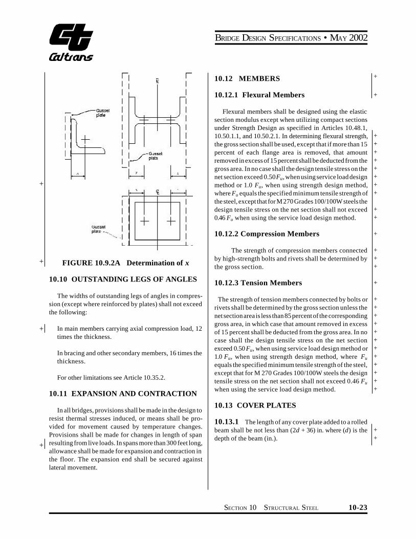
+
+
+
+
FIGURE 1092A Determination of x
1010 OUTSTANDING LEGS OF ANGLES
The widths of outstanding legs of angles in compresshysion (except where reinforced by plates) shall not exceed the following
In main members carrying axial compression load 12 times the thickness
In bracing and other secondary members 16 times the thickness
For other limitations see Article 10352
1011 EXPANSION AND CONTRACTION
In all bridges provisions shall be made in the design to resist thermal stresses induced or means shall be proshyvided for movement caused by temperature changes Provisions shall be made for changes in length of span resulting from live loads In spans more than 300 feet long allowance shall be made for expansion and contraction in the floor The expansion end shall be secured against lateral movement
BRIDGE DESIGN SPECIFICATIONS bull MAY 2002
1012 MEMBERS
10121 Flexural Members
Flexural members shall be designed using the elastic section modulus except when utilizing compact sections under Strength Design as specified in Articles 10481 105011 and 105021 In determining flexural strength the gross section shall be used except that if more than 15 percent of each flange area is removed that amount removed in excess of 15 percent shall be deducted from the gross area In no case shall the design tensile stress on the net section exceed 050Fu when using service load design method or 10 Fu when using strength design method where Fu equals the specified minimum tensile strength of the steel except that for M 270 Grades 100100W steels the design tensile stress on the net section shall not exceed 046 Fu when using the service load design method
10122 Compression Members
The strength of compression members connected by high-strength bolts and rivets shall be determined by the gross section
10123 Tension Members
The strength of tension members connected by bolts or rivets shall be determined by the gross section unless the net section area is less than 85 percent of the corresponding gross area in which case that amount removed in excess of 15 percent shall be deducted from the gross area In no case shall the design tensile stress on the net section exceed 050 Fu when using service load design method or 10 Fu when using strength design method where Fu
equals the specified minimum tensile strength of the steel except that for M 270 Grades 100100W steels the design tensile stress on the net section shall not exceed 046 Fu
when using the service load design method
1013 COVER PLATES
10131 The length of any cover plate added to a rolled beam shall be not less than (2d + 36) in where (d) is the depth of the beam (in)
+
+
+ + + + + + + +
+ +
+
+ + +
+
+ + + + + + + + + + + +
+ +
SECTION 10 STRUCTURAL STEEL 10-23
BRIDGE DESIGN SPECIFICATIONS bull MAY 2002
+
10132 Partial length welded cover plates shall not be used on flanges more than 08 inches thick for nonredundant load path structures subjected to repetitive loadings that produce tension or reversal of stress in the member
10133 The maximum thickness of a single cover plate on a flange shall not be greater than 2 times the thickness of the flange to which the cover plate is attached The total thickness of all cover plates should not be greater than 212 times the flange thickness
10134 Any partial length welded cover plate shall extend beyond the theoretical end by the terminal distance and it shall extend to a section where the stress range in the beam flange is equal to the allowable fatigue stress range for base metal adjacent to or connected by fillet welds The theoretical end of the cover plate when using service load design methods is the section at which the stress in the flange without that cover plate equals the allowable service load stress exclusive of fatigue considerations When using strength design methods the theoretical end of the cover plate is the section at which the flange strength without that cover plate equals the required strength for the design loads exclusive of fatigue requirements The terminal distance is two times the nominal cover plate width for cover plates not welded across their ends and 112 times for cover plates welded across their ends The width at ends of tapered cover plates shall be not less that 3 inches The weld connecting the cover plate to the flange in its terminal distance shall be continuous and of sufficient size to develop a total force of not less than the computed force in the cover plate at its theoretical end All welds connecting cover plates to beam flanges shall be continuous and shall not be smaller than the minimum size permitted by Article 102322
10135 Any partial length end-bolted cover plate shall extend beyond the theoretical end by the terminal distance equal to the length of the end-bolted portion and the cover plate shall extend to a section where the stress range in the beam flange is equal to the allowable fatigue stress range for base metal at ends of partial length welded cover plates with high-strength bolted slip-critical end connections (Table 1031B) Beams with end-bolted cover plates shall be fabricated in the following sequence drill holes clean faying surfaces install bolts weld The theoretical end of the end-bolted cover plate is determined in the same manner as that of a welded cover plate as specified in Article 1034 The bolts in the slip-critical connections of
the cover plate ends to the flange shall be of sufficient numbers to develop a total force of not less than the computed force in the cover plate at the theoretical end The slip resistance of the end-bolted connection shall be determined in accordance with Article 103232 for service load design and 105614 for load factor design The longitudinal welds connecting the cover plate to the beam flange shall be continuous and stop a distance equal to one bolt spacing before the first row of bolts in the endshybolted portion
1014 CAMBER
Girder should be cambered to compensate for dead load deflections and vertical curvature required by profile grade
1015 HEAT-CURVED ROLLED BEAMS AND WELDED PLATE GIRDERS
10151 Scope
This section pertains to rolled beans and welded Ishysection plate girders heat-curved to obtain a horizontal curvature Steels that are manufactured to a specified minimum yield strength greater than 50000 psi except for + Grade HPS 70W Steel shall not be heat-curved
10152 Minimum Radius of Curvature
101521 For heat-curved beams and girders the horizontal radius of curvature measured to the centerline of the girder web shall not be less than 150 feet and shall not be less than the larger of the values calculated (at any and all cross sections throughout the length of the girder) from the following two equations
440 b DR = +(10-1)Fy y tw
7500000 bR = (10-2) +Fyy
where
+Fy = specified minimum yield strength of the web (psi)
10-24 SECTION 10 STRUCTURAL STEEL
BRIDGE DESIGN SPECIFICATIONS bull MAY 2002
+ + + + + +
+
+
+ + + + + + + + + + + + + + + + +
y = ratio of the total cross-sectional area to the crossshysectional area of both flanges
b = widest flange width (in) D = clear distance between flanges (in) tw = web thickness (in) R = horizontal radius of curvature (in)
101522 In addition to the above requirements the radius shall not be less than 1000 feet when the flange thickness exceeds 3 inches or the flange width exceeds 30 inches
10153 Camber
To compensate for possible loss of camber of heatshycurved girders in service as residual stresses dissipate the amount of camber D (in) at any section along the length L of the girder shall be equal to
DDLD = (DM + DR ) (10-3)DM
002L2 Fy (1000 -R )D = Dagger 0R E Yo Ł 850 ł
where
DDL = camber at any point along the length L calcushylated by usual procedures to compensate for deflection due to dead loads or any other specishyfied loads (in)
DM = maximum value ofDDL within the lengthL (in) E = modulus of elasticity of steel (psi) Fy = specified minimum yield strength of girder flange
(psi) Yo = distance from the neutral axis to the extreme
outer fiber (in) (maximum distance for nonshysymmetrical sections)
R = radius of curvature (ft) L = span length for simple spans or for continuous
spans the distance between a simple end supshyport and the dead load contraflexure point or the distance between points of dead load contraflexure (in)
Camber loss between dead load contraflexure points adjashycent to piers is small and may be neglected
Note Part of the camber loss is attributable to construcshytion loads and will occur during construction of the bridge total camber loss will be complete after several months of in-service loads Therefore a portion of the camber increase (approximately 50 percent) should be included in the bridge profile Camber losses of this nature (but generally smaller in magnitude) are also known to occur in straight beams and girders
1016 TRUSSES
10161 General
101611 Component parts of individual truss memshybers may be connected by welds rivets or high-strength bolts
101612 Preference should be given to trusses with single intersection web systems Members shall be symmetrical about the central plane of the truss
101613 Trusses preferably shall have inclined end posts Laterally unsupported hip joints shall be avoided
101614 Main trusses shall be spaced a sufficient distance apart center to center to be secure against overturning by the design lateral forces +
101615 For the calculation of forces effective depths shall be assumed as follows
+
Riveted and bolted trusses distance between centers of gravity of the chords
Pin-connected trusses distance between centers of chord pins
10162 Truss Members
101621 Chord and web truss members shall usushyally be made in the following shapes
ldquoHrdquo sections made with two side segments (composed of angles or plates) with solid web perforated web or web of stay plates and lacing
SECTION 10 STRUCTURAL STEEL 10-25
BRIDGE DESIGN SPECIFICATIONS bull MAY 2002
+
+ +
Channel sections made with two angle segments with solid web perforated web or web of stay plates and lacing
Single Box sections made with side channels beams angles and plates or side segments of plates only connected top and bottom with perforated plates or stay plates and lacing
Single Box sections made with side channels beams angles and plates only connected at top with solid cover plates and at the bottom with perforated plates or stay plates and lacing
Double Box sections made with side channels beams angles and plates or side segments of plates only connected with a conventional solid web together with top and bottom perforated cover plates or stay plates and lacing
101622 If the shape of the truss permits comshypression chords shall be continuous
101623 In chords composed of angles in channel shaped members the vertical legs of the angles preferably shall extend downward
101624 If web members are subject to reversal of stress their end connections shall not be pinned Counters preferably shall be rigid Adjustable counters if used shall have open turnbuckles and in the design of these members an allowance of 10000 psi shall be made for initial stress Only one set of diagonals in any panel shall be adjustable Sleeve nuts and loop bars shall not be used
10163 Secondary Stresses
The design and details shall be such that secondary stresses will be as small as practicable Secondary stresses due to truss distortion or floor beam deflection usually need not be considered in any member the width of which measured parallel to the plane of distortion is less than one-tenth of its length If the secondary stress exceeds 4000 psi for tension members and 3000 psi for compresshysion members the excess shall be treated as a primary stress Stresses due to the flexural dead load moment of the member shall be considered as additional secondary stress
10164 Diaphragms
101641 There shall be diaphragms in the trusses at the end connections of floor beams
101642 The gusset plates engaging the pedestal pin at the end of the truss shall be connected by a diaphragm Similarly the webs of the pedestal shall if practicable be connected by a diaphragm
101643 There shall be a diaphragm between gusshyset plates engaging main members if the end tie plate is 4 feet or more from the point of intersection of the members
10165 Camber
The length of the truss members shall be such that the camber will be equal to or greater than the deflection produced by the dead load
10166 Working Lines and Gravity Axes
101661 Main members shall be proportioned so that their gravity axes will be as nearly as practicable in the center of the section
101662 In compression members of unsymmetrishycal section such as chord sections formed of side segshyments and a cover plate the gravity axis of the section shall coincide as nearly as practicable with the working line except that eccentricity may be introduced to counteract dead load bending In two-angle bottom chord or diagonal members the working line may be taken as the gage line nearest the back of the angle or at the center of gravity for welded trusses
10167 Portal and Sway Bracing
101671 Through truss spans shall have portal bracing preferably of the two-plane or box type rigidly connected to the end post and the top chord flanges and as deep as the clearance will allow If a single plane portal is used it shall be located preferably in the central transverse plane of the end posts with diaphragms beshytween the webs of the posts to provide for a distribution of the portal stresses The portal bracing shall be designed to take the full end reaction of the top chord lateral system and the end posts shall be designed to transfer this reaction to the truss bearings
10-26 SECTION 10 STRUCTURAL STEEL
BRIDGE DESIGN SPECIFICATIONS bull MAY 2002
101672 Through truss spans shall have sway bracing 5 feet or more deep at each intermediate panel point Top lateral struts shall be at least as deep as the top chord
101673 Deck truss spans shall have sway bracshying in the plane of the end posts and at all intermediate panel points This bracing shall extend the full depth of the trusses below the floor system The end sway bracing
+ shall be proportioned to carry the entire upper lateral load to the supports through the end posts of the truss
10168 Perforated Cover Plates
When perforated cover plates are used the following provisions shall govern their design
101681 The ratio of length in direction of stress to width of perforation shall not exceed two
101682 The clear distance between perforations in the direction of stress shall not be less than the distance between points of support
101683 The clear distance between the end pershyforation and the end of the cover plate shall not be less than 125 times the distance between points of support
101684 The point of support shall be the inner line of fasteners or fillet welds connecting the perforated plate to the flanges For plates butt welded to the flange edge of rolled segments the point of support may be taken as the weld whenever the ratio of the outstanding flange width to flange thickness of the rolled segment is less than seven Otherwise the point of support shall be the root of the flange of the rolled segment
101685 The periphery of the perforation at all points shall have a minimum radius of 112 inches
101686 For thickness of metal see Article 10352
10169 Stay Plates
101691 Where the open sides of compression members are not connected by perforated plates such members shall be provided with lacing bars and shall have stay plates as near each end as practicable Stay plates shall be provided at intermediate points where the lacing is interrupted In main members the length of the end stay
plates between end fasteners shall be not less than 114
times the distance between points of support and the length of intermediate stay plates not less than34 of that distance In lateral struts and other secondary members the overall length of end and intermediate stay plates shall be not less than 34 of the distance between points of support
101692 The point of support shall be the inner line of fasteners or fillet welds connecting the stay plates to the flanges For stay plates butt welded to the flange edge of rolled segment the point of support may be taken as the weld whenever the ratio of outstanding flange width to flange thickness or the rolled segment is less than seven Otherwise the point of support shall be the root of flange of rolled segment When stay plates are butt welded to rolled segments of a member the allowable stress in the member shall be determined in accordance with Article 103 Terminations of butt welds shall be ground smooth
101693 The separate segments of tension memshybers composed of shapes may be connected by perforated plates or by stay plates or end stay plates and lacing End stay plates shall have the same minimum length as specishyfied for end stay plates on main compression members and intermediate stay plates shall have a minimum length of 34 o f that specified for intermediate stay plates on main compression members The clear distance between stay plates on tension members shall not exceed 3 feet
101694 The thickness of stay plates shall be not less than150 of the distance between points of support for main members and 160 of that distance for bracing memshybers Stay plates shall be connected by not less than three fasteners on each side and in members having lacing bars the last fastener in the stay plates preferably shall also pass through the end of the adjacent bar
101610 Lacing Bars
When lacing bars are used the following provisions shall govern their design
1016101 Lacing bars of compression members shall be so spaced that the slenderness ratio of the portion of the flange included between the lacing bar connections will be not more than 40 or more than23 of the slenderness ratio of the member
+
+ + + + +
+ + +
+
SECTION 10 STRUCTURAL STEEL 10-27
BRIDGE DESIGN SPECIFICATIONS bull MAY 2002
1016102 The section of the lacing bars shall be determined by the formula for axial compression in which L is taken as the distance along the bar between its connections to the main segments for single lacing and as 70 percent of that distance for double lacing
1016103 If the distance across the member beshytween fastener lines in the flanges is more than 15 inches and a bar with a single fastener in the connection is used the lacing shall be double and fastened at the intersecshytions
1016104 The angle between the lacing bars and the axis of the member shall be approximately 45 degrees for double lacing and 60 degrees for single lacing
1016105 Lacing bars may be shapes or flat bars For main members the minimum thickness of flat bars shall be 140 of the distance along the bar between its connecshytions for single lacing and 160 for double lacing For bracing members the limits shall be 150 for single lacing and 175 for double lacing
1016106 The diameter of fasteners in lacing bars shall not exceed one-third the width of the bar There shall be at least two fasteners in each end of lacing bars connected to flanges more than 5 inches in width
101611 Gusset Plates
1016111 Gusset or connection plates preferably shall be used for connecting main members except when the members are pin-connected The fasteners connecting each member shall be symmetrical with the axis of the member so far as practicable and the full development of the elements of the member shall be given consideration The gusset plates shall be designed to resist shear axial force and bending moments acting on the weakest or critical section
1016112 Re-entrant cuts except curves made for appearance shall be avoided as far as practicable
1016113 If the length of unsupported edge of a gusset plate exceeds the value of the expression 11000 Fy times its thickness the edge shall be stiffshyened
expression 11000 yF for the following grades of steel
Fy (psi) 11000 yF
36000 58 50000 49 70000 42 90000 37 100000 35
1016114 Listed below are the values of the
101612 Half-Through Truss Spans
1016121 The vertical truss members and the floor beams and their connections in half-through truss spans shall be proportioned to resist a lateral force of not less than 300 pounds per linear foot applied at the top chord panel points of each truss
1016122 The compression chord shall be deshysigned as a compression member with elastic lateral supports at the panel points The strength of the compresshysion chord so determined shall exceed the maximum force from dead load live load and impact in any panel of the compression chord by not less than 50 percent
101613 Fastener Pitch in Ends of Compression Members
In the ends of compression members the pitch of fasteners connecting the component parts of the member shall not exceed four times the diameter of the fastener for a length equal to 112 times the maximum width of the member Beyond this point the pitch shall be increased gradually for a length equal to 112 times the maximum width of the member until the maximum pitch is reached
101614 Net Section of Riveted or High-Strength Bolted Tension Members
1016141 The net section of a riveted or highshystrength bolted tension member is the sum of the net sections of its component parts The net section of a part is the product of the thickness of the part multiplied by its least net width
For a discussion of columns with elastic lateral supports refer to Timoshenko amp Gere ldquoTheory of Elastic Stabilityrdquo McGraw-Hill Book Co Second Edition P70
+ + + + + + +
+ + +
+
10-28 SECTION 10 STRUCTURAL STEEL
BRIDGE DESIGN SPECIFICATIONS bull MAY 2002
1016142 The net width for any chain of holes extending progressively across the part shall be obtained by deducting from the gross width the sum of the diamshyeters of all the holes in the chain and adding for each gage space in the chain the quantity
2s+ (10-4)4g
where
+ s = pitch of any two successive holes in the chain + (in) + g = gage of the same holes (in)
The net section of the part is obtained from the chain that gives the least net width
1016143 For angles the gross width shall be the sum of the widths of the legs less the thickness The gage for holes in opposite legs shall be the sum of gages from back of angle less the thickness
1016144 At a splice the total force in the member+ + being spliced is transferred by fasteners to the splice
material
1016145 When determining the stress on any least net width of either splice material or member being spliced
+
+
the amount of the force previously transferred by fastenshyers adjacent to the section being investigated shall be
+ considered in determining the stress on the net section
1016146 The diameter of the hole shall be taken as 18 inch greater than the nominal diameter of the rivet or high-strength bolt unless larger holes are permitted in accordance with Article 1024
1017 BENTS AND TOWERS
10171 General
Bents preferably shall be composed of two supporting columns and the bents usually shall be united in pairs to form towers The design of members for bents and towers is governed by applicable articles
10172 Single Bents
Single bents shall have hinged ends or else shall be designed to resist bending
10173 Batter
Bents preferably shall have a sufficient spread at the base to prevent uplift under the design lateral loadings In general the width of a bent at its base shall be not less than one-third of its height
10174 Bracing
101741 Towers shall be braced both transversely and longitudinally with stiff members having either welded high-strength bolted or riveted connections The sections of members of longitudinal bracing in each panel shall not be less than those of the members in corresponding panels of the transverse bracing
101742 The bracing of long columns shall be designed to fix the column about both axes at or near the same point
101743 Horizontal diagonal bracing shall be placed in all towers having more than two vertical panels at alternate intermediate panel points
10175 Bottom Struts
The bottom struts of towers shall be strong enough to slide the movable shoes with the structure unloaded the coefficient of friction being assumed at 025 Provision for expansion of the tower bracing shall be made in the column bearings
1018 SPLICES
10181 General
101811 Design Strength
Splices may be made by rivets by high-strength bolts or by the use of welding In general splices whether in tension compression bending or shear shall be deshysigned in the cases of the service load design or the strength design methods for a capacity based on not less than 100 percent of the allowable design strength in the
+
+ + + + + +
SECTION 10 STRUCTURAL STEEL 10-29
BRIDGE DESIGN SPECIFICATIONS bull MAY 2002
+ member taking into account the bolt holes Bolted and + riveted splices in flexural members shall satisfy the requireshy+ ments of Article 10182 Bolted and riveted splices in + compression members shall satisfy the requirements of + Article 10183 Bolted and riveted splices in tension memshy+ bers shall satisfy the requirements of Article 10184 + Bolted and riveted splices in tension members shall also + satisfy the requirements of Article 10194 Welded splices + shall satisfy the requirements of Article 10185 Where a + section changes at a splice the small section is to be used + to satisfy the above splice requirements
101812 Fillers
1018121 For fillers 14 inch and thicker in bolted or riveted axially loaded connections including girder flange splices additional fasteners shall be required to distribute the total stress in the member uniformly over the combined section of the member and the filler The filler shall either
+ be extended beyond the splice material and secured by + additional fasteners or as an alternate to extending the + filler an equivalent number of fasteners may be included + in the connection Fillers 14 inch and thicker need not be + extended and developed provided that the design shear + strength of the fasteners specified in Article 1056132 in
the case of the strength design method and in the Tables 10323A and 10323B in the case of the service load design method is reduced by the following factor R
R=[(1+g)(1+2g)] (10-4a)
where g=Af Ap
+ Af = sum of the area of the fillers on the top and + bottom of the connected plate (in2) + +
Ap = smaller of either the connected plate area or the sum of the splice plate areas on the top and
+ bottom of the connected plate (in2)
+ The design slip force specified in Article 1056132 in + the case of the strength design method and in Article
1032321 in the case of the service load design method for slip-critical connections shall not be adjusted for the effect of the fillers Fillers 14 inch or more in thickness shall consist of not more than two plates unless special permisshysion is given by the Engineer
1018122 For bolted web splices with thickness differences of 116 inch or less no filler plates are required
1018123 Fillers for welded splices shall conform to the requirements of the AISIAASHTOAWS D15 Bridge Welding Code
101813 Design Force for Flange Splice Plates
For a flange splice with inner and outer splice plates the flange design force may be assumed to be divided equally to the inner and outer plates and their connections when the areas of the inner and outer plates do not differ by more than 10 percent When the areas of the inner and outer plates differ by more than 10 percent the design force in each splice plate and its connection shall be determined by multiplying the flange design force by the ratio of the area of the splice plate under consideration to the total area of the inner and outer splice plates For this case the shear strength of the connection shall be checked for the maximum calculated splice plate force acting on a single shear plane The slip resistance of high-strength bolted connections for a flange splice with inner and outer splice plates shall always be checked for the flange design force divided equally to the two slip planes
101814 Truss Chords and Columns
Splices in truss chords and columns shall be located as near to the panel points as practicable and usually on the side where smaller stress occurs The arrangement of plates angles or other splice elements shall be such as to make proper provision for the stresses both axial and bending in the component parts of the member spliced
10182 Flexural Member
101821 General
1018211 Splices shall preferably be made at or near points of dead load contraflexure in continuous spans and at points of the section change
1018212 In both flange and web splices there shall be not less than two rows of bolts on each side of the joint
1018213 Oversize or slotted holes shall not be used in either the member or the splice plates at the bolted splices
1018214 In both flange and web splices highshystrength bolted connections shall be proportioned to prevent slip during erection of the steel and during the casting or placing of the deck
+ + +
10-30 SECTION 10 STRUCTURAL STEEL
BRIDGE DESIGN SPECIFICATIONS bull MAY 2002
+
+ + +
+ +
+
+
+ + + + + + + +
+ +
+ +
+
+ + + + +
+
1018215 Deleted
1018216 Flange and web splices in areas of stress reversal shall be checked for both positive and negative flexure
1018217 Riveted and bolted flange angle splices shall include two angles one on each side of the flexural member
101822 Flange Splices
1018221 For checking the strength of flange splices an effective area A shall be used for the flanges and forethe individual splice plates as follows
For flanges and their splice plates subject to tension
Ae= wnt + b Ag pound Ag (10-4b)
where
Wn = least net width of the flange or splice plate computed as specified in Article101614 (in)
t = flange or splice plate thickness (in) Ag = gross area of the flange or splice plate (in2) b = 00 for M 270 Grade 100100W steels or when
holes exceed 1 14 inch in diameter = 015 for all other steels and when holes are less
than or equal to 1 14 inch in diameter
The diameter of the holes shall be taken as specified in Article 1016146
For the flanges and their splice plates subject to compression
Ae = Ag (10-4c)
1018222 In the case of the strength design method the splice plates shall be proportioned for a design force P equal to a design stressF times the smaller effectivecu cuarea A on either side of the splice F is defined ase cufollows
Fcu =a Fyf (10-4d)
where a = 10 except that a lower value equal to (MuMy) may
be used for flanges in compression at sections where Mu is less than My
Mu = design bending strength of the section in posishytive or negative flexure at the point of splice whichever causes the maximum compressive stress due to the factored loads at the mid-thickshyness of the flange under consideration (lb-in)
My = moment capacity at first yield for the section at the point of splice used to compute Mu (lb-in) For composite sectionsMy shall be calculated in accordance with Article1050(c) For hybrid secshytions My shall be computed in accordance with Article 1053
Fyf = specified minimum yield strength of the flange (psi)
In calculating Mu and My holes in the flange subject to tension shall be accounted for as specified in Article 1012 For a flange splice with inner and outer splice plates the flange design forces shall be proportioned to the inner and outer plates and their connections as specified in Article 101813 The effective area Ae of each splice plate shall be sufficient to prevent yielding of the splice plate under its calculated portion of the design force As a minimum the connections for both the top and bottom flange splices shall be proportioned to develop the design force in the flange through shear in the bolts and bearing at the bolt holes as specified in Article 1056132 Where filler plates are required the requirements of Article 1018121 shall also be satisfied
As a minimum high-strength bolted connection for both top and bottom flange splices shall be proportioned to prevent slip at an overload design forcePfo defined as follows
Pfo=permilfo RpermilAg (10-4e)
where
fo = maximum flexural stress due to Group I loading divided by 13 at the mid-thickness of the flange under consideration for the smaller section at the point of splice (psi)
R = reduction factor for hybrid girders specified in Article 105312 R shall be taken equal to 10 when fo is less than or equal to the specified minimum yield strength of the web Fyw For homogeneous girders R shall always be taken equal to 10
+ +
+
+ + + +
SECTION 10 STRUCTURAL STEEL 10-31
BRIDGE DESIGN SPECIFICATIONS bull MAY 2002
+ +
+ + + +
+
+ +
+
Ag = smaller gross flange area on either side of the splice (in2)
fo andR shall be computed using the gross section of the member The slip resistance of the connection shall be computed from Equation (10-172)
1018223 In the case of the service load design method the splice plates shall be proportioned for a design force Pcf equal to the allowable flexural stress for the flange under consideration at the point of splice Fb times the smaller effective area A on either side of theesplice
For a flange splice with inner and outer splice plates the flange design forces shall be proportioned to the inner and outer plates and their connections as specified in Article 101813 The effective area Ae of each splice plate shall be sufficient to ensure that the stress in the splice plate does not exceed the allowable flexural stress under its calculated portion of the design force As a minimum the connections for both the top and bottom flange splices shall be proportioned to develop the design force in the flange through shear in the bolts and bearing at the bolt holes as specified in Table 10323B Where filler plates are required the requirements of Article 1018121 shall also be satisfied
As a minimum high-strength bolted connection for both top and bottom flange splices shall be proportioned to prevent slip at a force equal to the flange design stress times the smaller value of the gross flange area on either side of the splice The slip resistance of the connection shall be determined as specified in Article 1032321
1018224 (Deleted)
101823 Web Splices
1018231 In general web splice plates and their connections shall be proportioned for shear a moment due to eccentricity of the shear at the point of splice and a portion of the flexural moment that is assumed to be resisted by the web at the point of splice Webs shall be spliced symmetrically by plates on each side The web splice plates shall extend as near as practical for the full depth between flanges
1018232 In the case of the strength design method web splice plates and their connections shall be proporshytioned for a design shear V equal to the shear capacitywuof the smaller web at the point of splice V u
1018233 In the case of the strength design method web splice plates and their connections shall be proporshytioned for a design momentMvu due to the eccentricity of the design shear at the point of splice defined as follows
Mvu=Vwue (10-4f)
where
Vwu = design shear in the web at the point of splice defined in Article 1018232 (lb)
e = distance from the centerline of the splice to the centroid of the connection on the side of the joint under consideration (in)
1018234 In the case of the strength design method web splice plates and their connections shall be proporshytioned for a design momentM representing the portionwuof the flexural moment that is assumed to be resisted by the web M shall be applied at the mid-depth of the web Forwusections where the neutral axis is not located at mid-depth of the web a horizontal design force resultant in the web at the point of splice H shall also be applied at the midshywudepth of the web M and H may be computed aswu wufollows
For non-compact sections
wu M = 2
12 wt D ( cr RF yfF+ ) (10-4g)
wu H = (2
w yf
t D F )crRF- (10-4h)
For compact sections
wu M = 4
w ywt F ( 2D )24 cy- (10-4i)
wu H 2 w o ywt y F= (10-4j)
+ + + +
+
+
+ +
+ +
+
+
+
+
+
+
+
+
10-32 SECTION 10 STRUCTURAL STEEL
BRIDGE DESIGN SPECIFICATIONS bull MAY 2002
+
+ + + + + + + + + + + + +
+ + + +
+
+
+
+
+
where
Fcr = design flexural strength specified in Articles 105012 and 105022 for composite sections or determined by MuSxcRb where Mu is defined as in Articles 10482 10483 10484 for noncomposite sections (psi)
Fyf = specified minimum yield strength of the flange (psi)
Fyw =specified minimum yield strength of the web (psi) yo = distance form the mid-depth of the web to the
plastic neutral axis (in) D = clear unsupported distance between flange comshy
ponents (in) tw = web thickness (in)
1018235 In the case of the strength design method web splice plates and their connections shall be proporshytioned for the most critical combination of V M M wu vu wuand H The connections shall be proportioned as eccenshywutrically loaded connections to resist the resultant design force through shear in the bolts and bearing at the bolt holes as specified in Article 1056132 In addition as a minimum high-strength bolted connections for web splices shall be proportioned as eccentrically loaded connections to prevent slip under the most critical combination of 1) an overload design shear V 2) an overload designwomoment M due to the eccentricity of the overloadvodesign shear 3) an overload design momentM appliedwoat mid-depth of the web representing the portion of the flexural moment that is assumed to be resisted by the web and 4) for sections where the neutral axis is not located at mid-depth of the web an overload horizontal design force H applied at mid-depth of the web as followswo
Vwo = Vo (10-4k)
Mvo = Vwoe (10-4l)
where
Vo = maximum shear in the web due to Group I loading divided by 13 at the point of splice (lb)
Mwo and Hwo may be determined as follows
t D2 wMwo = (10-4m)fo - fof12
t DwHw = 2 ( fo - fof ) (10-4n)
where
fo = maximum flexural stress due to Group I loading divided by 13 at the mid-thickness of the flange under consideration for smaller section at the point of splice (positive for tension negative for compression) (psi)
fof = flexural stress due to Group I loading divided by 13 at the mid-thickness of the other flange at the point of splice concurrent with fo in the flange under consideration (positive for tension negashytive for compression) (psi)
fo and fof shall be computed using the gross section of the member The maximum resultant force on the eccentrically loaded connection shall not exceed the slip resistance computed from Equation (10-172) with Nb taken equal to 10
1018236 In the case of the service load design method web splice plates and their connections shall be proportioned for a design shear stress in the web at the point of splice Fw equal to the allowable shear stress in the web at the point of splice Fv
1018237 In the case of the service load design method web splice plates and their connections shall be proportioned for a design moment Mv due to the eccentricity of the design shear at the point of splice defined as follows
Mv = FwDtwe (10-4o)
where
Fw = design shear stress in the web at the point of splice defined in Article 1018236 (psi)
D =web depth (in) tw = web thickness (in)
1018238 In the case of the service design method web splice plates and their connections shall be proporshytioned for a design moment Mw representing the portion of the flexural moment that is assumed to be resisted by the web Mw shall be applied at the mid-depth of the web For sections where the neutral axis is not located at mid-depth of the web a horizontal design force resultant in the web at the point of splice Hw shall also be applied at the midshydepth of the webMw andHw may be computed as follows
t D2 wM = ( RF + F ) (10-4p)w bc bt12
+ +
+ + + +
+
+ + + +
+
+
SECTION 10 STRUCTURAL STEEL 10-33
Note (b) deleted +
BRIDGE DESIGN SPECIFICATIONS bull MAY 2002
+
+ + + +
+
+ +
wH = t D (F - RF ) (10-4q)w bt bc2
where
= allowable compression flange stress specifiedFbc in Table 10321A (psi)
= allowable tension flange stress specified inFbt Table 10321A (psi)
1018239 In the case of the service load design method web splice plates and their connections shall be proportioned for the most critical combination of F Dt w wM M andH The connections shall be proportioned asv w weccentrically loaded connections to resist the resultant design force through shear in the bolts and bearing at the bolt holes as specified in Table 10323B In addition as a minimum high-strength bolted connections for web splices shall be proportioned as eccentrically loaded conshynections to prevent slip under the most critical combinashytion of F Dt M M and H M and H shall bew w v w w w wcomputed using the gross section of the member The
FIGURE 10185A
maximum resultant force on the eccentrically loaded conshynection shall not exceed the slip resistance computed from Table 1032321 with Nb taken equal to 10
10183 Compression Members
Compression members such as columns and chords shall have ends in close contact at riveted and bolted splices Splices of such members which will be fabricated and erected with close inspection and detailed with milled ends in full contact bearing at the splices may be held in place by means of splice plates and rivets or high-strength bolts proportioned for not less than 50 percent of the lower allowable design strength of sections spliced The strength of compression members connected by high-strength bolts or rivets shall be determined using the gross section
10184 Tension Members
The tension strength of splice components shall be based on Article 10123 For calculating the net section the provisions of Articles 109 and 101614 shall apply
Splice Details
+ + +
10-34 SECTION 10 STRUCTURAL STEEL
BRIDGE DESIGN SPECIFICATIONS bull MAY 2002
+
+ + + +
+ +
As a minimum in the case of the strength design method high-strength bolted connections for splices in tension members shall be proportioned to prevent slip at an overload design forcePo equal to the maximum tensile stress in the member due to Group I loading divided by 13 times the gross section of member The slip resistance shall be computed from Equation (10-172) In the case of the service load design method high-strength bolted connections shall be proportioned to prevent slip at a force equal to the allowable design strength specified in Article 101811 times the gross area of the member The slip resistance of the connection shall be determined as specified in Article 1032321
10185 Welding Splices
101851 Tension and compression members may be spliced by means of full penetration butt welds prefershyably without the use of splice plates
101852 Splices shall not be welded in field
101853 Material of different widths spliced by butt welds shall have transitions conforming to Figure 10185A At butt weld splices joining material of different thicknesses there shall be a uniform slope between the offset surfaces of not more than 1 in 2 12 with respect to the surface of either part
10191 General
101911 Except as otherwise provided herein conshynections for main members shall be designed in the cases of the service load design and the strength design methshyods for a capacity based on not less than 100 percent of the allowable design strength in the member
101912 Connections shall be made symmetrical about the axis of the members insofar as practicable Connecshytions except for lacing bars and handrails shall contain not less than two fasteners or equivalent weld
101913 Members including bracing preferably shall be so connected that their gravity axes will intersect in a point Eccentric connections shall be avoided if practishycable but if unavoidable the members shall be so proporshytioned that the combined forces will not exceed the allowshyable design strength
101914 In the case of connections which transfer total member shear at the end of the member the gross section shall be taken as the gross section of the conshynected elements
10192 End Connections of Floor Beams and Stringers
101921 The end connection shall be designed for calculated member loads The end connection angles of floor beams and stringers shall be not less than38 inch in finished thickness Except in cases of special end floor beam details each end connection for floor beams and stringers shall be made with two angles The length of these angles shall be as great as the flanges will permit Bracket or shelf angles which may be used to furnish support during erection shall not be considered in detershymining the number of fasteners required to transmit end shear
101922 End connection details shall be designed with special care to provide clearance for making the field connection
101923 End connections of stringers and floor beams preferably shall be bolted with high-strength bolts however they may be riveted or welded In the case of welded end connections they shall be designed for the vertical loads and the end bending moment resulting from the deflection of the members
101924 Where timber stringers frame into steel floor beams shelf angles with stiffeners shall be provided to carry the total reaction Shelf angles shall be not less than 716 inch thick
10193 End Connections of Diaphragms and Cross Frames
101931 The end connections for diaphragms or cross frames in straight rolled-beam and plate girder bridges shall be designed for the calculated member loads
101932 Vertical connection plates such as transshyverse stiffeners which connect diaphragms or cross frames to the beam or girder shall be rigidly connected to both top and bottom flanges
SECTION 10 STRUCTURAL STEEL 10-35
BRIDGE DESIGN SPECIFICATIONS bull MAY 2002
+ 10194 Block Shear Rupture Strength
+ 101941 General
+ Block shear rupture is one of several possible failure + modes for splices connections gusset plates and tension + members Block shear rupture failure is developed when + the net section of one segment ruptures and the gross + section of a perpendicular segment yields The web + connections of coped beams all tension connections + including connection plates splice plates and gusset + plates and tension members shall be investigated to + ensure that the adequate block shear rupture strength is + provided
+ 101942 Allowable Block Shear Rupture + Stress
+ In the Service Load Design Method calculated tension + stress based on the gross section shall not exceed the + allowable block shear rupture stress obtained from the + following equations
+ for vntn AA Dagger 06
+ ( ) gtnuvgybs AF AF AF 055033 += (10-4a)
+ for vntn AA lt 06
+ ( ) gtgyvnubs AF AF AF 055033 += (10-4b)
+ where
+ Ag = gross area of whole connected material (in2) + Avg = gross area along the plane resisting shear (in2) + Avn = net area along the plane resisting shear (in2) + Atg = gross area along the plane resisting tension (in2) + Atn = net area along the plane resisting tension (in2) + Fy = specified minimum yield strength of the conshy+ nected materials (psi) + Fu = specified minimum tensile strength of the conshy+ nected materials (psi) + Fbs = allowable block shear rupture stress (psi)
101943 Design Block Shear Rupture + Strength +
In the Strength Design Method calculated tension + force shall not exceed the design block shear rupture + strength obtained from the following equations +
+ for vntn AA Dagger 058 +
( tn )uvgybsbs F AF AT += 058f (10-4c)
for vntn AA lt 058
( tg )yvnubsbs F AF AT += 058f (10-4d)
where Tbs = design block shear rupture strength (lb) f bs = 08 reduction factor for block shear rupture
strength
1020 DIAPHRAGMS AND CROSS FRAMES
10201 General
Rolled beam and plate girder spans shall be provided with cross frames or diaphragms at each support and with + cross frames or diaphragms placed in all bays and spaced at intervals not to exceed 25 feet Diaphragms for rolled beams shall be at least13 and preferably12 the beam depth and for plate girders shall be at least 12 and preferably 34 the girder depth Cross frames shall be as deep as + practicable Cross frames shall preferably be of the cross type or vee type End cross frames or diaphragms shall be proportioned to adequately transmit all the lateral forces to the bearings Intermediate cross frames shall be normal + to the main beams and girders when the supports are skewed more than twenty degrees (20deg) Cross frames on horizontally curved steel girder bridges shall be designed as main members with adequate provisions for transfer of lateral forces from the girder flanges Cross frames and diaphragms shall be designed for horizontal wind loads as described in Article 10212 seismic loads and other applishy + cable loads +
10-36 SECTION 10 STRUCTURAL STEEL
BRIDGE DESIGN SPECIFICATIONS bull MAY 2002
+ 10202 Horizontal Force
+ The maximum horizontal force FD (lb) in the transshyverse diaphragms and cross frames is obtained from the following
+ FD = 114WSd (10-5)
+ where + W = wind load along the exterior flange (lbft) + Sd = diaphragm spacing (ft)
+ 102021 Deleted
+ 102022 Deleted
+ 10203 Deleted
+ 1021 LATERAL BRACING
10211 The need for lateral bracing shall be investigated + for wind loads seismic loads and other applicable lateral + loads Flanges attached to concrete decks or other decks
of comparable rigidity will not require lateral bracing
10212 A horizontal wind force of 50 pounds per square foot shall be applied to the area of the superstructure exposed in elevation Half this force shall be applied in the
+ plane of each flange The maximum induced stresses f + (psi) in the bottom flange of each girder in the system + when top flanges are continuously supported can be + computed from the following
+ cbR ff = (10-6)
+ [ ] ł
)
Ł
(-= -
bracing is provided when no bottomlateral
1102272 2 3SdLR
(10-7)
+ [ ] ł
)
Ł
(-= -
bracingis provided whenbottomlateral
0640059 1 2SdLR
(10-8)
+ 2
72
ff
cb cb t b
Mf = (10-9)
+ 2008 dcb W SM = (10-10)
L = span length (ft) tf = thickness of flange (in) + bf = width of flange (in) +
The stresses in flanges of each girder in the system + when top flanges are not continuously supported shall be + computed using the structural system in the plane of the + flanges under consideration The allowable stress shall be + factored in accordance with Article 322
10213 When required lateral bracing shall be placed in the exterior bays between diaphragms or cross frames All required lateral bracing shall be placed in or near the plane of the flange being braced
10214 Where beams or girders comprise the main members of through spans such members shall be stiffened against lateral deformation by means of gusset plates or knee braces with solid webs which shall be connected to the stiffeners on the main members and the floor beams If the unsupported length of the edge of the gusset plate (or solid web) exceeds 60 times its thickness the plate or web shall have a stiffening plate or angles connected along its unsupported edge
10215 Through truss spans deck truss spans and spandrel braced arches shall have top and bottom lateral bracing
10216 Bracing shall be composed of angles other shapes or welded sections The smallest angle used in bracing shall be 3 by 212 inches There shall be not less than 2 fasteners or equivalent weld in each end connection of the angles
10217 If a double system of bracing is used both systems may be considered effective simultaneously if the members meet the requirements both as tension and compression members The members shall be connected at their intersections
10218 The lateral bracing of compression chords preferably shall be as deep as the chords and effectively connected to both flanges
1022 CLOSED SECTIONS AND POCKETS
10221 Closed sections and pockets or depressions that will retain water shall be avoided where practicable
SECTION 10 STRUCTURAL STEEL 10-37
BRIDGE DESIGN SPECIFICATIONS bull MAY 2002
+ +
+ + + + +
Pockets shall be provided with effective drain holes or be filled with waterproofing material
10222 Details shall be so arranged that the destructive effects of bird life and the retention of dirt leaves and other foreign matter will be reduced to a minimum Where angles are used either singly or in pairs they preferably shall be placed with the vertical legs extending downward Structural tees preferably shall have the web extending downward
1023 WELDING
10231 General
102311 Steel base metal to be welded weld metal and welding design details shall conform to the requireshyments of the ANSIAASHTOAWS D15 Bridge Welding Code and the current Standard Specifications of the California Department of Transportation
102312 Welding symbols shall conform with the latest edition of the American Welding Society Publicashytion AWS A24
102313 Fabrication shall conform to the Stanshydard Specifications of the California Department of Transshyportation For fracture critical members see the AASHTO ldquoGuide Specifications for Fracture Critical Non-Redunshydant Steel Bridge Membersrdquo
10232 Effective Size of Fillet Welds
102321 Maximum Size of Fillet Welds
The maximum size of a fillet weld that may be assumed in the design of a connection shall be such that the stresses in the adjacent base material do not exceed the values allowed in Article 1032 The maximum size that may be used along edges of connected parts shall be
(1) Along edges of material less than14 inch thick the maximum size may be equal to the thickness of the material
(2) Along edges of material 14 inch or more in thickshyness the maximum size shall be 116 inch less than the thickness of the material unless the weld is especially designated on the drawings to be built out to obtain full throat thickness
102322 Minimum Size of Fillet Welds
The minimum fillet weld size shall be as shown in the following table
Base Metal Thickness of Minimum Size Thicker Part of Fillet Weld Jointed (T) in mm in mm
T pound 34 T pound 190 14 6 Single-pass WeldsT gt 34 Tgt 190 516 8 must be used
Except that the weld size need not exceed the thickness of the thinner part jointed For this exception particular care should be taken to provide sufficient preheat to ensure weld soundness
Smaller fillet welds may be approved by the Engineer based upon applied stress and the use of appropriate preheat
10233 Minimum Effective Length of Fillet Welds
The minimum effective length of a fillet weld shall be four times its size and in no case less than 112 inches
10234 Fillet Weld End Returns
Fillet welds which support a tensile force that is not parallel to the axis of the weld or which are proportioned to withstand repeated stress shall not terminate at corners of parts or members but shall be returned continuously full size around the corner for a length equal to twice the weld size where such return can be made in the same plane End returns shall be indicated on design and detail drawshyings
10235 Seal Welds
Seal welding shall preferably be accomplished by a continuous weld combining the functions of sealing and strength changing section only as the required strength or the requirements of minimum size fillet weld based on material thickness may necessitate
10-38 SECTION 10 STRUCTURAL STEEL
BRIDGE DESIGN SPECIFICATIONS bull MAY 2002
+
+ + + + + + +
+
+ + + + + + + + + + +
+ +
1024 FASTENERS
10241 General
102411 In proportioning fasteners for shear and tension the cross-sectional area based upon the nominal diameter shall be used Galvanization of AASHTO M253 (ASTM A490) and A354 Grade BD high strength bolts is not permitted due to hydrogen embrittlement problems These fasteners must be carefully evaluated before being utilized Requirements for bolts in these specifications shall be used for threaded rods threaded studs and anchor rods where applicable
102412 High-strength bolts may be substituted for Grade 1 rivets (ASTM A 502) or ASTM A307 bolts When AASHTO M 164 (ASTM A325) high-strength bolts are substituted for ASTM A307 bolts they shall be tightened to the full effort of a man using an ordinary spud wrench
102413 All bolts except high-strength bolts tensioned to the requirements of the Standard Specificashytions of the California Department of Transportation shall have single self-locking nut double nuts or a nut with a thread locking system (anaerobic adhesive) to prevent nut loosening The thread locking system is the preferred method for bolt diameters of one inch or less The thread locking system shall not be used on bolt diameters greater than one inch When using the double nut method a torque value for the jam nut relative to the main nut shall be shown on the plans to assure that a reasonable effort will be made to lock the two nuts together
102414 Joints required to resist shear between their connected parts are designated as either slip-critical or bearing-type connections Slip-critical joints are reshyquired for joints subject to stress reversal heavy impact loads severe vibration or where stress and strain due to joint slippage would be detrimental to the serviceability of the structure They include
(1) Joints subject to fatigue loading (2) Joints with bolts installed in oversized holes (3) Except where the Engineer intends otherwise and
so indicates in the contract documents joints with bolts installed in slotted holes where the force on the joint is in a direction other than normal (beshytween approximately 80 and 100 degrees) to the axis of the slot
(4) Joints subject to significant load reversal (5) Joints in which welds and bolts share in transmitshy
ting load at a common faying surface (6) Joints in which in the judgment of the Engineer
any slip would be critical to the performance of the joint or the structure and so designated on the contract plans and specifications
102415 High-strength bolted connections subshyject to tension or combined shear and tension shall be designed as slip-critical connections
102416 Bolted bearing-type connections using high-strength bolts shall be limited to members in comshypression and secondary members
102417 The effective bearing area of a fastener shall be its diameter multiplied by the thickness of the metal on which it bears In metal less than 38 inch thick counshytersunk fasteners shall not be assumed to carry stress In metal 38 inch thick and over one-half the depth of counshytersink shall be omitted in calculating the bearing area
102418 In determining whether the bolt threads are excluded from the shear planes of the contact surfaces thread length of bolts shall be calculated as two thread pitches greater than the specified thread length as an allowance for thread run out
102419 In bearing-type connections pull-out shear in a plate should be investigated between the end of the plate and the end row of fasteners (See Table 10323B footnote h or Article 105613)
+ +
SECTION 10 STRUCTURAL STEEL 10-39
5
BRIDGE DESIGN SPECIFICATIONS bull MAY 2002
+
TABLE 10242 Nominal Hole Dimension
Hole Dimension (in)Bolt
Standard Oversize Short Slot Long SlotDiameter (in) (Diameter) (Diameter) (Width x Length) (Width x Length)
1116 1316
58 1116 x 78
1116 x 1916
34 1316
1516 1316 x 1 1316 x 178
78 1516 1116
15 16 x 118 1516 x 2316
11 41 1116 1116 x 1516 1116 x 212
(d + 116) x (d + 38) (d + 116) x (25 x d)Dagger 118 d + 116 d + 516
10242 Hole Types 100 degrees) to the axis of the slot Long slotted holes may
Hole types for high-strength bolted connections are be used in one of the connected parts at any individual standard holes oversize holes short slotted holes and faying surface without regard for the direction of applied long slotted holes The nominal dimensions for each type load on connections which satisfy the requirements of hole shall be not greater than those shown in Table 10242 Article 1032321 or Article 105731 as applicable
10243 Washer Requirements102421 In the absence of approval by the Engishyneer for use of other hole types standard holes shall be used in high-strength bolted connections Design details shall provide for washers in highshy
strength bolted connections as follows 102422 When approved by the Engineer overshy
size short slotted hole or long slotted holes may be used 102431 Where the outer face of the bolted parts subject to the following joint detail requirements has slope greater than 120 with respect to a plane normal
to the bolt axis a hardened beveled washer shall be used to compensate for the lack of parallelism Beveled washers
of connections which satisfy the requirements of Article 1024221 Oversize holes may be used in all plies
other than the standard 16 slope shall be detailed in the plans
shall not be used in bearing-type connections 1032321 or Article 10573 as applicable Oversize holes
102432 Hardened washers are not required for connections using AASHTO M164 (ASTM A325) and
or all plies of high-strength bolted connections designed 1024222 Short slotted holes may be used in any
AASHTO M253 (ASTM A490) bolts except as required in on the basis of Table 10323B or Table 1056A as appli- Articles 102433 through 102437 cable provided the load is applied approximately normal (between 80 and 100 degrees) to the axis of the slot Short 102433 Hardened washers shall be used under slotted holes may be used without regard for the direction the element turned in tightening and to cover oversize or of applied load in any or all plies of connections which short slotted holes in the outer ply satisfy the requirements of Article 1032321 or Article 105731 as applicable 102434 Irrespective of the tightening method
hardened washers shall be used under both the head and the nut when AASHTO M253 (ASTM A490) bolts are to
of the connected parts at any individual faying surface in 1024223 Long slotted holes may be used in one
be installed in material having a specified yield strength high-strength bolted connections designed on the basis less than 40000 psi of Table 10323B or Table 1056A as applicable provided the load is applied approximately normal (between 80 and
+ +
+ + +
+ +
+ + +
10-40 SECTION 10 STRUCTURAL STEEL
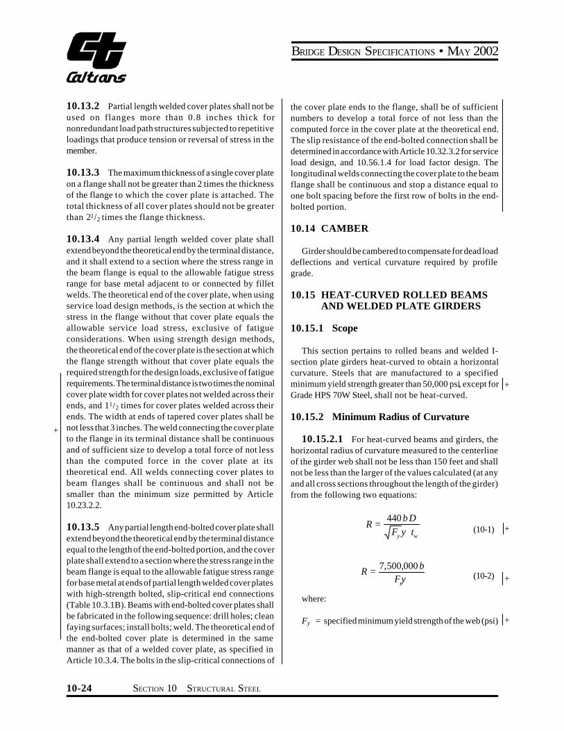
BRIDGE DESIGN SPECIFICATIONS bull MAY 2002
+
10132 Partial length welded cover plates shall not be used on flanges more than 08 inches thick for nonredundant load path structures subjected to repetitive loadings that produce tension or reversal of stress in the member
10133 The maximum thickness of a single cover plate on a flange shall not be greater than 2 times the thickness of the flange to which the cover plate is attached The total thickness of all cover plates should not be greater than 212 times the flange thickness
10134 Any partial length welded cover plate shall extend beyond the theoretical end by the terminal distance and it shall extend to a section where the stress range in the beam flange is equal to the allowable fatigue stress range for base metal adjacent to or connected by fillet welds The theoretical end of the cover plate when using service load design methods is the section at which the stress in the flange without that cover plate equals the allowable service load stress exclusive of fatigue considerations When using strength design methods the theoretical end of the cover plate is the section at which the flange strength without that cover plate equals the required strength for the design loads exclusive of fatigue requirements The terminal distance is two times the nominal cover plate width for cover plates not welded across their ends and 112 times for cover plates welded across their ends The width at ends of tapered cover plates shall be not less that 3 inches The weld connecting the cover plate to the flange in its terminal distance shall be continuous and of sufficient size to develop a total force of not less than the computed force in the cover plate at its theoretical end All welds connecting cover plates to beam flanges shall be continuous and shall not be smaller than the minimum size permitted by Article 102322
10135 Any partial length end-bolted cover plate shall extend beyond the theoretical end by the terminal distance equal to the length of the end-bolted portion and the cover plate shall extend to a section where the stress range in the beam flange is equal to the allowable fatigue stress range for base metal at ends of partial length welded cover plates with high-strength bolted slip-critical end connections (Table 1031B) Beams with end-bolted cover plates shall be fabricated in the following sequence drill holes clean faying surfaces install bolts weld The theoretical end of the end-bolted cover plate is determined in the same manner as that of a welded cover plate as specified in Article 1034 The bolts in the slip-critical connections of
the cover plate ends to the flange shall be of sufficient numbers to develop a total force of not less than the computed force in the cover plate at the theoretical end The slip resistance of the end-bolted connection shall be determined in accordance with Article 103232 for service load design and 105614 for load factor design The longitudinal welds connecting the cover plate to the beam flange shall be continuous and stop a distance equal to one bolt spacing before the first row of bolts in the endshybolted portion
1014 CAMBER
Girder should be cambered to compensate for dead load deflections and vertical curvature required by profile grade
1015 HEAT-CURVED ROLLED BEAMS AND WELDED PLATE GIRDERS
10151 Scope
This section pertains to rolled beans and welded Ishysection plate girders heat-curved to obtain a horizontal curvature Steels that are manufactured to a specified minimum yield strength greater than 50000 psi except for + Grade HPS 70W Steel shall not be heat-curved
10152 Minimum Radius of Curvature
101521 For heat-curved beams and girders the horizontal radius of curvature measured to the centerline of the girder web shall not be less than 150 feet and shall not be less than the larger of the values calculated (at any and all cross sections throughout the length of the girder) from the following two equations
440 b DR = +(10-1)Fy y tw
7500000 bR = (10-2) +Fyy
where
+Fy = specified minimum yield strength of the web (psi)
10-24 SECTION 10 STRUCTURAL STEEL
BRIDGE DESIGN SPECIFICATIONS bull MAY 2002
+ + + + + +
+
+
+ + + + + + + + + + + + + + + + +
y = ratio of the total cross-sectional area to the crossshysectional area of both flanges
b = widest flange width (in) D = clear distance between flanges (in) tw = web thickness (in) R = horizontal radius of curvature (in)
101522 In addition to the above requirements the radius shall not be less than 1000 feet when the flange thickness exceeds 3 inches or the flange width exceeds 30 inches
10153 Camber
To compensate for possible loss of camber of heatshycurved girders in service as residual stresses dissipate the amount of camber D (in) at any section along the length L of the girder shall be equal to
DDLD = (DM + DR ) (10-3)DM
002L2 Fy (1000 -R )D = Dagger 0R E Yo Ł 850 ł
where
DDL = camber at any point along the length L calcushylated by usual procedures to compensate for deflection due to dead loads or any other specishyfied loads (in)
DM = maximum value ofDDL within the lengthL (in) E = modulus of elasticity of steel (psi) Fy = specified minimum yield strength of girder flange
(psi) Yo = distance from the neutral axis to the extreme
outer fiber (in) (maximum distance for nonshysymmetrical sections)
R = radius of curvature (ft) L = span length for simple spans or for continuous
spans the distance between a simple end supshyport and the dead load contraflexure point or the distance between points of dead load contraflexure (in)
Camber loss between dead load contraflexure points adjashycent to piers is small and may be neglected
Note Part of the camber loss is attributable to construcshytion loads and will occur during construction of the bridge total camber loss will be complete after several months of in-service loads Therefore a portion of the camber increase (approximately 50 percent) should be included in the bridge profile Camber losses of this nature (but generally smaller in magnitude) are also known to occur in straight beams and girders
1016 TRUSSES
10161 General
101611 Component parts of individual truss memshybers may be connected by welds rivets or high-strength bolts
101612 Preference should be given to trusses with single intersection web systems Members shall be symmetrical about the central plane of the truss
101613 Trusses preferably shall have inclined end posts Laterally unsupported hip joints shall be avoided
101614 Main trusses shall be spaced a sufficient distance apart center to center to be secure against overturning by the design lateral forces +
101615 For the calculation of forces effective depths shall be assumed as follows
+
Riveted and bolted trusses distance between centers of gravity of the chords
Pin-connected trusses distance between centers of chord pins
10162 Truss Members
101621 Chord and web truss members shall usushyally be made in the following shapes
ldquoHrdquo sections made with two side segments (composed of angles or plates) with solid web perforated web or web of stay plates and lacing
SECTION 10 STRUCTURAL STEEL 10-25
BRIDGE DESIGN SPECIFICATIONS bull MAY 2002
+
+ +
Channel sections made with two angle segments with solid web perforated web or web of stay plates and lacing
Single Box sections made with side channels beams angles and plates or side segments of plates only connected top and bottom with perforated plates or stay plates and lacing
Single Box sections made with side channels beams angles and plates only connected at top with solid cover plates and at the bottom with perforated plates or stay plates and lacing
Double Box sections made with side channels beams angles and plates or side segments of plates only connected with a conventional solid web together with top and bottom perforated cover plates or stay plates and lacing
101622 If the shape of the truss permits comshypression chords shall be continuous
101623 In chords composed of angles in channel shaped members the vertical legs of the angles preferably shall extend downward
101624 If web members are subject to reversal of stress their end connections shall not be pinned Counters preferably shall be rigid Adjustable counters if used shall have open turnbuckles and in the design of these members an allowance of 10000 psi shall be made for initial stress Only one set of diagonals in any panel shall be adjustable Sleeve nuts and loop bars shall not be used
10163 Secondary Stresses
The design and details shall be such that secondary stresses will be as small as practicable Secondary stresses due to truss distortion or floor beam deflection usually need not be considered in any member the width of which measured parallel to the plane of distortion is less than one-tenth of its length If the secondary stress exceeds 4000 psi for tension members and 3000 psi for compresshysion members the excess shall be treated as a primary stress Stresses due to the flexural dead load moment of the member shall be considered as additional secondary stress
10164 Diaphragms
101641 There shall be diaphragms in the trusses at the end connections of floor beams
101642 The gusset plates engaging the pedestal pin at the end of the truss shall be connected by a diaphragm Similarly the webs of the pedestal shall if practicable be connected by a diaphragm
101643 There shall be a diaphragm between gusshyset plates engaging main members if the end tie plate is 4 feet or more from the point of intersection of the members
10165 Camber
The length of the truss members shall be such that the camber will be equal to or greater than the deflection produced by the dead load
10166 Working Lines and Gravity Axes
101661 Main members shall be proportioned so that their gravity axes will be as nearly as practicable in the center of the section
101662 In compression members of unsymmetrishycal section such as chord sections formed of side segshyments and a cover plate the gravity axis of the section shall coincide as nearly as practicable with the working line except that eccentricity may be introduced to counteract dead load bending In two-angle bottom chord or diagonal members the working line may be taken as the gage line nearest the back of the angle or at the center of gravity for welded trusses
10167 Portal and Sway Bracing
101671 Through truss spans shall have portal bracing preferably of the two-plane or box type rigidly connected to the end post and the top chord flanges and as deep as the clearance will allow If a single plane portal is used it shall be located preferably in the central transverse plane of the end posts with diaphragms beshytween the webs of the posts to provide for a distribution of the portal stresses The portal bracing shall be designed to take the full end reaction of the top chord lateral system and the end posts shall be designed to transfer this reaction to the truss bearings
10-26 SECTION 10 STRUCTURAL STEEL
BRIDGE DESIGN SPECIFICATIONS bull MAY 2002
101672 Through truss spans shall have sway bracing 5 feet or more deep at each intermediate panel point Top lateral struts shall be at least as deep as the top chord
101673 Deck truss spans shall have sway bracshying in the plane of the end posts and at all intermediate panel points This bracing shall extend the full depth of the trusses below the floor system The end sway bracing
+ shall be proportioned to carry the entire upper lateral load to the supports through the end posts of the truss
10168 Perforated Cover Plates
When perforated cover plates are used the following provisions shall govern their design
101681 The ratio of length in direction of stress to width of perforation shall not exceed two
101682 The clear distance between perforations in the direction of stress shall not be less than the distance between points of support
101683 The clear distance between the end pershyforation and the end of the cover plate shall not be less than 125 times the distance between points of support
101684 The point of support shall be the inner line of fasteners or fillet welds connecting the perforated plate to the flanges For plates butt welded to the flange edge of rolled segments the point of support may be taken as the weld whenever the ratio of the outstanding flange width to flange thickness of the rolled segment is less than seven Otherwise the point of support shall be the root of the flange of the rolled segment
101685 The periphery of the perforation at all points shall have a minimum radius of 112 inches
101686 For thickness of metal see Article 10352
10169 Stay Plates
101691 Where the open sides of compression members are not connected by perforated plates such members shall be provided with lacing bars and shall have stay plates as near each end as practicable Stay plates shall be provided at intermediate points where the lacing is interrupted In main members the length of the end stay
plates between end fasteners shall be not less than 114
times the distance between points of support and the length of intermediate stay plates not less than34 of that distance In lateral struts and other secondary members the overall length of end and intermediate stay plates shall be not less than 34 of the distance between points of support
101692 The point of support shall be the inner line of fasteners or fillet welds connecting the stay plates to the flanges For stay plates butt welded to the flange edge of rolled segment the point of support may be taken as the weld whenever the ratio of outstanding flange width to flange thickness or the rolled segment is less than seven Otherwise the point of support shall be the root of flange of rolled segment When stay plates are butt welded to rolled segments of a member the allowable stress in the member shall be determined in accordance with Article 103 Terminations of butt welds shall be ground smooth
101693 The separate segments of tension memshybers composed of shapes may be connected by perforated plates or by stay plates or end stay plates and lacing End stay plates shall have the same minimum length as specishyfied for end stay plates on main compression members and intermediate stay plates shall have a minimum length of 34 o f that specified for intermediate stay plates on main compression members The clear distance between stay plates on tension members shall not exceed 3 feet
101694 The thickness of stay plates shall be not less than150 of the distance between points of support for main members and 160 of that distance for bracing memshybers Stay plates shall be connected by not less than three fasteners on each side and in members having lacing bars the last fastener in the stay plates preferably shall also pass through the end of the adjacent bar
101610 Lacing Bars
When lacing bars are used the following provisions shall govern their design
1016101 Lacing bars of compression members shall be so spaced that the slenderness ratio of the portion of the flange included between the lacing bar connections will be not more than 40 or more than23 of the slenderness ratio of the member
+
+ + + + +
+ + +
+
SECTION 10 STRUCTURAL STEEL 10-27
BRIDGE DESIGN SPECIFICATIONS bull MAY 2002
1016102 The section of the lacing bars shall be determined by the formula for axial compression in which L is taken as the distance along the bar between its connections to the main segments for single lacing and as 70 percent of that distance for double lacing
1016103 If the distance across the member beshytween fastener lines in the flanges is more than 15 inches and a bar with a single fastener in the connection is used the lacing shall be double and fastened at the intersecshytions
1016104 The angle between the lacing bars and the axis of the member shall be approximately 45 degrees for double lacing and 60 degrees for single lacing
1016105 Lacing bars may be shapes or flat bars For main members the minimum thickness of flat bars shall be 140 of the distance along the bar between its connecshytions for single lacing and 160 for double lacing For bracing members the limits shall be 150 for single lacing and 175 for double lacing
1016106 The diameter of fasteners in lacing bars shall not exceed one-third the width of the bar There shall be at least two fasteners in each end of lacing bars connected to flanges more than 5 inches in width
101611 Gusset Plates
1016111 Gusset or connection plates preferably shall be used for connecting main members except when the members are pin-connected The fasteners connecting each member shall be symmetrical with the axis of the member so far as practicable and the full development of the elements of the member shall be given consideration The gusset plates shall be designed to resist shear axial force and bending moments acting on the weakest or critical section
1016112 Re-entrant cuts except curves made for appearance shall be avoided as far as practicable
1016113 If the length of unsupported edge of a gusset plate exceeds the value of the expression 11000 Fy times its thickness the edge shall be stiffshyened
expression 11000 yF for the following grades of steel
Fy (psi) 11000 yF
36000 58 50000 49 70000 42 90000 37 100000 35
1016114 Listed below are the values of the
101612 Half-Through Truss Spans
1016121 The vertical truss members and the floor beams and their connections in half-through truss spans shall be proportioned to resist a lateral force of not less than 300 pounds per linear foot applied at the top chord panel points of each truss
1016122 The compression chord shall be deshysigned as a compression member with elastic lateral supports at the panel points The strength of the compresshysion chord so determined shall exceed the maximum force from dead load live load and impact in any panel of the compression chord by not less than 50 percent
101613 Fastener Pitch in Ends of Compression Members
In the ends of compression members the pitch of fasteners connecting the component parts of the member shall not exceed four times the diameter of the fastener for a length equal to 112 times the maximum width of the member Beyond this point the pitch shall be increased gradually for a length equal to 112 times the maximum width of the member until the maximum pitch is reached
101614 Net Section of Riveted or High-Strength Bolted Tension Members
1016141 The net section of a riveted or highshystrength bolted tension member is the sum of the net sections of its component parts The net section of a part is the product of the thickness of the part multiplied by its least net width
For a discussion of columns with elastic lateral supports refer to Timoshenko amp Gere ldquoTheory of Elastic Stabilityrdquo McGraw-Hill Book Co Second Edition P70
+ + + + + + +
+ + +
+
10-28 SECTION 10 STRUCTURAL STEEL
BRIDGE DESIGN SPECIFICATIONS bull MAY 2002
1016142 The net width for any chain of holes extending progressively across the part shall be obtained by deducting from the gross width the sum of the diamshyeters of all the holes in the chain and adding for each gage space in the chain the quantity
2s+ (10-4)4g
where
+ s = pitch of any two successive holes in the chain + (in) + g = gage of the same holes (in)
The net section of the part is obtained from the chain that gives the least net width
1016143 For angles the gross width shall be the sum of the widths of the legs less the thickness The gage for holes in opposite legs shall be the sum of gages from back of angle less the thickness
1016144 At a splice the total force in the member+ + being spliced is transferred by fasteners to the splice
material
1016145 When determining the stress on any least net width of either splice material or member being spliced
+
+
the amount of the force previously transferred by fastenshyers adjacent to the section being investigated shall be
+ considered in determining the stress on the net section
1016146 The diameter of the hole shall be taken as 18 inch greater than the nominal diameter of the rivet or high-strength bolt unless larger holes are permitted in accordance with Article 1024
1017 BENTS AND TOWERS
10171 General
Bents preferably shall be composed of two supporting columns and the bents usually shall be united in pairs to form towers The design of members for bents and towers is governed by applicable articles
10172 Single Bents
Single bents shall have hinged ends or else shall be designed to resist bending
10173 Batter
Bents preferably shall have a sufficient spread at the base to prevent uplift under the design lateral loadings In general the width of a bent at its base shall be not less than one-third of its height
10174 Bracing
101741 Towers shall be braced both transversely and longitudinally with stiff members having either welded high-strength bolted or riveted connections The sections of members of longitudinal bracing in each panel shall not be less than those of the members in corresponding panels of the transverse bracing
101742 The bracing of long columns shall be designed to fix the column about both axes at or near the same point
101743 Horizontal diagonal bracing shall be placed in all towers having more than two vertical panels at alternate intermediate panel points
10175 Bottom Struts
The bottom struts of towers shall be strong enough to slide the movable shoes with the structure unloaded the coefficient of friction being assumed at 025 Provision for expansion of the tower bracing shall be made in the column bearings
1018 SPLICES
10181 General
101811 Design Strength
Splices may be made by rivets by high-strength bolts or by the use of welding In general splices whether in tension compression bending or shear shall be deshysigned in the cases of the service load design or the strength design methods for a capacity based on not less than 100 percent of the allowable design strength in the
+
+ + + + + +
SECTION 10 STRUCTURAL STEEL 10-29
BRIDGE DESIGN SPECIFICATIONS bull MAY 2002
+ member taking into account the bolt holes Bolted and + riveted splices in flexural members shall satisfy the requireshy+ ments of Article 10182 Bolted and riveted splices in + compression members shall satisfy the requirements of + Article 10183 Bolted and riveted splices in tension memshy+ bers shall satisfy the requirements of Article 10184 + Bolted and riveted splices in tension members shall also + satisfy the requirements of Article 10194 Welded splices + shall satisfy the requirements of Article 10185 Where a + section changes at a splice the small section is to be used + to satisfy the above splice requirements
101812 Fillers
1018121 For fillers 14 inch and thicker in bolted or riveted axially loaded connections including girder flange splices additional fasteners shall be required to distribute the total stress in the member uniformly over the combined section of the member and the filler The filler shall either
+ be extended beyond the splice material and secured by + additional fasteners or as an alternate to extending the + filler an equivalent number of fasteners may be included + in the connection Fillers 14 inch and thicker need not be + extended and developed provided that the design shear + strength of the fasteners specified in Article 1056132 in
the case of the strength design method and in the Tables 10323A and 10323B in the case of the service load design method is reduced by the following factor R
R=[(1+g)(1+2g)] (10-4a)
where g=Af Ap
+ Af = sum of the area of the fillers on the top and + bottom of the connected plate (in2) + +
Ap = smaller of either the connected plate area or the sum of the splice plate areas on the top and
+ bottom of the connected plate (in2)
+ The design slip force specified in Article 1056132 in + the case of the strength design method and in Article
1032321 in the case of the service load design method for slip-critical connections shall not be adjusted for the effect of the fillers Fillers 14 inch or more in thickness shall consist of not more than two plates unless special permisshysion is given by the Engineer
1018122 For bolted web splices with thickness differences of 116 inch or less no filler plates are required
1018123 Fillers for welded splices shall conform to the requirements of the AISIAASHTOAWS D15 Bridge Welding Code
101813 Design Force for Flange Splice Plates
For a flange splice with inner and outer splice plates the flange design force may be assumed to be divided equally to the inner and outer plates and their connections when the areas of the inner and outer plates do not differ by more than 10 percent When the areas of the inner and outer plates differ by more than 10 percent the design force in each splice plate and its connection shall be determined by multiplying the flange design force by the ratio of the area of the splice plate under consideration to the total area of the inner and outer splice plates For this case the shear strength of the connection shall be checked for the maximum calculated splice plate force acting on a single shear plane The slip resistance of high-strength bolted connections for a flange splice with inner and outer splice plates shall always be checked for the flange design force divided equally to the two slip planes
101814 Truss Chords and Columns
Splices in truss chords and columns shall be located as near to the panel points as practicable and usually on the side where smaller stress occurs The arrangement of plates angles or other splice elements shall be such as to make proper provision for the stresses both axial and bending in the component parts of the member spliced
10182 Flexural Member
101821 General
1018211 Splices shall preferably be made at or near points of dead load contraflexure in continuous spans and at points of the section change
1018212 In both flange and web splices there shall be not less than two rows of bolts on each side of the joint
1018213 Oversize or slotted holes shall not be used in either the member or the splice plates at the bolted splices
1018214 In both flange and web splices highshystrength bolted connections shall be proportioned to prevent slip during erection of the steel and during the casting or placing of the deck
+ + +
10-30 SECTION 10 STRUCTURAL STEEL
BRIDGE DESIGN SPECIFICATIONS bull MAY 2002
+
+ + +
+ +
+
+
+ + + + + + + +
+ +
+ +
+
+ + + + +
+
1018215 Deleted
1018216 Flange and web splices in areas of stress reversal shall be checked for both positive and negative flexure
1018217 Riveted and bolted flange angle splices shall include two angles one on each side of the flexural member
101822 Flange Splices
1018221 For checking the strength of flange splices an effective area A shall be used for the flanges and forethe individual splice plates as follows
For flanges and their splice plates subject to tension
Ae= wnt + b Ag pound Ag (10-4b)
where
Wn = least net width of the flange or splice plate computed as specified in Article101614 (in)
t = flange or splice plate thickness (in) Ag = gross area of the flange or splice plate (in2) b = 00 for M 270 Grade 100100W steels or when
holes exceed 1 14 inch in diameter = 015 for all other steels and when holes are less
than or equal to 1 14 inch in diameter
The diameter of the holes shall be taken as specified in Article 1016146
For the flanges and their splice plates subject to compression
Ae = Ag (10-4c)
1018222 In the case of the strength design method the splice plates shall be proportioned for a design force P equal to a design stressF times the smaller effectivecu cuarea A on either side of the splice F is defined ase cufollows
Fcu =a Fyf (10-4d)
where a = 10 except that a lower value equal to (MuMy) may
be used for flanges in compression at sections where Mu is less than My
Mu = design bending strength of the section in posishytive or negative flexure at the point of splice whichever causes the maximum compressive stress due to the factored loads at the mid-thickshyness of the flange under consideration (lb-in)
My = moment capacity at first yield for the section at the point of splice used to compute Mu (lb-in) For composite sectionsMy shall be calculated in accordance with Article1050(c) For hybrid secshytions My shall be computed in accordance with Article 1053
Fyf = specified minimum yield strength of the flange (psi)
In calculating Mu and My holes in the flange subject to tension shall be accounted for as specified in Article 1012 For a flange splice with inner and outer splice plates the flange design forces shall be proportioned to the inner and outer plates and their connections as specified in Article 101813 The effective area Ae of each splice plate shall be sufficient to prevent yielding of the splice plate under its calculated portion of the design force As a minimum the connections for both the top and bottom flange splices shall be proportioned to develop the design force in the flange through shear in the bolts and bearing at the bolt holes as specified in Article 1056132 Where filler plates are required the requirements of Article 1018121 shall also be satisfied
As a minimum high-strength bolted connection for both top and bottom flange splices shall be proportioned to prevent slip at an overload design forcePfo defined as follows
Pfo=permilfo RpermilAg (10-4e)
where
fo = maximum flexural stress due to Group I loading divided by 13 at the mid-thickness of the flange under consideration for the smaller section at the point of splice (psi)
R = reduction factor for hybrid girders specified in Article 105312 R shall be taken equal to 10 when fo is less than or equal to the specified minimum yield strength of the web Fyw For homogeneous girders R shall always be taken equal to 10
+ +
+
+ + + +
SECTION 10 STRUCTURAL STEEL 10-31
BRIDGE DESIGN SPECIFICATIONS bull MAY 2002
+ +
+ + + +
+
+ +
+
Ag = smaller gross flange area on either side of the splice (in2)
fo andR shall be computed using the gross section of the member The slip resistance of the connection shall be computed from Equation (10-172)
1018223 In the case of the service load design method the splice plates shall be proportioned for a design force Pcf equal to the allowable flexural stress for the flange under consideration at the point of splice Fb times the smaller effective area A on either side of theesplice
For a flange splice with inner and outer splice plates the flange design forces shall be proportioned to the inner and outer plates and their connections as specified in Article 101813 The effective area Ae of each splice plate shall be sufficient to ensure that the stress in the splice plate does not exceed the allowable flexural stress under its calculated portion of the design force As a minimum the connections for both the top and bottom flange splices shall be proportioned to develop the design force in the flange through shear in the bolts and bearing at the bolt holes as specified in Table 10323B Where filler plates are required the requirements of Article 1018121 shall also be satisfied
As a minimum high-strength bolted connection for both top and bottom flange splices shall be proportioned to prevent slip at a force equal to the flange design stress times the smaller value of the gross flange area on either side of the splice The slip resistance of the connection shall be determined as specified in Article 1032321
1018224 (Deleted)
101823 Web Splices
1018231 In general web splice plates and their connections shall be proportioned for shear a moment due to eccentricity of the shear at the point of splice and a portion of the flexural moment that is assumed to be resisted by the web at the point of splice Webs shall be spliced symmetrically by plates on each side The web splice plates shall extend as near as practical for the full depth between flanges
1018232 In the case of the strength design method web splice plates and their connections shall be proporshytioned for a design shear V equal to the shear capacitywuof the smaller web at the point of splice V u
1018233 In the case of the strength design method web splice plates and their connections shall be proporshytioned for a design momentMvu due to the eccentricity of the design shear at the point of splice defined as follows
Mvu=Vwue (10-4f)
where
Vwu = design shear in the web at the point of splice defined in Article 1018232 (lb)
e = distance from the centerline of the splice to the centroid of the connection on the side of the joint under consideration (in)
1018234 In the case of the strength design method web splice plates and their connections shall be proporshytioned for a design momentM representing the portionwuof the flexural moment that is assumed to be resisted by the web M shall be applied at the mid-depth of the web Forwusections where the neutral axis is not located at mid-depth of the web a horizontal design force resultant in the web at the point of splice H shall also be applied at the midshywudepth of the web M and H may be computed aswu wufollows
For non-compact sections
wu M = 2
12 wt D ( cr RF yfF+ ) (10-4g)
wu H = (2
w yf
t D F )crRF- (10-4h)
For compact sections
wu M = 4
w ywt F ( 2D )24 cy- (10-4i)
wu H 2 w o ywt y F= (10-4j)
+ + + +
+
+
+ +
+ +
+
+
+
+
+
+
+
+
10-32 SECTION 10 STRUCTURAL STEEL
BRIDGE DESIGN SPECIFICATIONS bull MAY 2002
+
+ + + + + + + + + + + + +
+ + + +
+
+
+
+
+
where
Fcr = design flexural strength specified in Articles 105012 and 105022 for composite sections or determined by MuSxcRb where Mu is defined as in Articles 10482 10483 10484 for noncomposite sections (psi)
Fyf = specified minimum yield strength of the flange (psi)
Fyw =specified minimum yield strength of the web (psi) yo = distance form the mid-depth of the web to the
plastic neutral axis (in) D = clear unsupported distance between flange comshy
ponents (in) tw = web thickness (in)
1018235 In the case of the strength design method web splice plates and their connections shall be proporshytioned for the most critical combination of V M M wu vu wuand H The connections shall be proportioned as eccenshywutrically loaded connections to resist the resultant design force through shear in the bolts and bearing at the bolt holes as specified in Article 1056132 In addition as a minimum high-strength bolted connections for web splices shall be proportioned as eccentrically loaded connections to prevent slip under the most critical combination of 1) an overload design shear V 2) an overload designwomoment M due to the eccentricity of the overloadvodesign shear 3) an overload design momentM appliedwoat mid-depth of the web representing the portion of the flexural moment that is assumed to be resisted by the web and 4) for sections where the neutral axis is not located at mid-depth of the web an overload horizontal design force H applied at mid-depth of the web as followswo
Vwo = Vo (10-4k)
Mvo = Vwoe (10-4l)
where
Vo = maximum shear in the web due to Group I loading divided by 13 at the point of splice (lb)
Mwo and Hwo may be determined as follows
t D2 wMwo = (10-4m)fo - fof12
t DwHw = 2 ( fo - fof ) (10-4n)
where
fo = maximum flexural stress due to Group I loading divided by 13 at the mid-thickness of the flange under consideration for smaller section at the point of splice (positive for tension negative for compression) (psi)
fof = flexural stress due to Group I loading divided by 13 at the mid-thickness of the other flange at the point of splice concurrent with fo in the flange under consideration (positive for tension negashytive for compression) (psi)
fo and fof shall be computed using the gross section of the member The maximum resultant force on the eccentrically loaded connection shall not exceed the slip resistance computed from Equation (10-172) with Nb taken equal to 10
1018236 In the case of the service load design method web splice plates and their connections shall be proportioned for a design shear stress in the web at the point of splice Fw equal to the allowable shear stress in the web at the point of splice Fv
1018237 In the case of the service load design method web splice plates and their connections shall be proportioned for a design moment Mv due to the eccentricity of the design shear at the point of splice defined as follows
Mv = FwDtwe (10-4o)
where
Fw = design shear stress in the web at the point of splice defined in Article 1018236 (psi)
D =web depth (in) tw = web thickness (in)
1018238 In the case of the service design method web splice plates and their connections shall be proporshytioned for a design moment Mw representing the portion of the flexural moment that is assumed to be resisted by the web Mw shall be applied at the mid-depth of the web For sections where the neutral axis is not located at mid-depth of the web a horizontal design force resultant in the web at the point of splice Hw shall also be applied at the midshydepth of the webMw andHw may be computed as follows
t D2 wM = ( RF + F ) (10-4p)w bc bt12
+ +
+ + + +
+
+ + + +
+
+
SECTION 10 STRUCTURAL STEEL 10-33
Note (b) deleted +
BRIDGE DESIGN SPECIFICATIONS bull MAY 2002
+
+ + + +
+
+ +
wH = t D (F - RF ) (10-4q)w bt bc2
where
= allowable compression flange stress specifiedFbc in Table 10321A (psi)
= allowable tension flange stress specified inFbt Table 10321A (psi)
1018239 In the case of the service load design method web splice plates and their connections shall be proportioned for the most critical combination of F Dt w wM M andH The connections shall be proportioned asv w weccentrically loaded connections to resist the resultant design force through shear in the bolts and bearing at the bolt holes as specified in Table 10323B In addition as a minimum high-strength bolted connections for web splices shall be proportioned as eccentrically loaded conshynections to prevent slip under the most critical combinashytion of F Dt M M and H M and H shall bew w v w w w wcomputed using the gross section of the member The
FIGURE 10185A
maximum resultant force on the eccentrically loaded conshynection shall not exceed the slip resistance computed from Table 1032321 with Nb taken equal to 10
10183 Compression Members
Compression members such as columns and chords shall have ends in close contact at riveted and bolted splices Splices of such members which will be fabricated and erected with close inspection and detailed with milled ends in full contact bearing at the splices may be held in place by means of splice plates and rivets or high-strength bolts proportioned for not less than 50 percent of the lower allowable design strength of sections spliced The strength of compression members connected by high-strength bolts or rivets shall be determined using the gross section
10184 Tension Members
The tension strength of splice components shall be based on Article 10123 For calculating the net section the provisions of Articles 109 and 101614 shall apply
Splice Details
+ + +
10-34 SECTION 10 STRUCTURAL STEEL
BRIDGE DESIGN SPECIFICATIONS bull MAY 2002
+
+ + + +
+ +
As a minimum in the case of the strength design method high-strength bolted connections for splices in tension members shall be proportioned to prevent slip at an overload design forcePo equal to the maximum tensile stress in the member due to Group I loading divided by 13 times the gross section of member The slip resistance shall be computed from Equation (10-172) In the case of the service load design method high-strength bolted connections shall be proportioned to prevent slip at a force equal to the allowable design strength specified in Article 101811 times the gross area of the member The slip resistance of the connection shall be determined as specified in Article 1032321
10185 Welding Splices
101851 Tension and compression members may be spliced by means of full penetration butt welds prefershyably without the use of splice plates
101852 Splices shall not be welded in field
101853 Material of different widths spliced by butt welds shall have transitions conforming to Figure 10185A At butt weld splices joining material of different thicknesses there shall be a uniform slope between the offset surfaces of not more than 1 in 2 12 with respect to the surface of either part
10191 General
101911 Except as otherwise provided herein conshynections for main members shall be designed in the cases of the service load design and the strength design methshyods for a capacity based on not less than 100 percent of the allowable design strength in the member
101912 Connections shall be made symmetrical about the axis of the members insofar as practicable Connecshytions except for lacing bars and handrails shall contain not less than two fasteners or equivalent weld
101913 Members including bracing preferably shall be so connected that their gravity axes will intersect in a point Eccentric connections shall be avoided if practishycable but if unavoidable the members shall be so proporshytioned that the combined forces will not exceed the allowshyable design strength
101914 In the case of connections which transfer total member shear at the end of the member the gross section shall be taken as the gross section of the conshynected elements
10192 End Connections of Floor Beams and Stringers
101921 The end connection shall be designed for calculated member loads The end connection angles of floor beams and stringers shall be not less than38 inch in finished thickness Except in cases of special end floor beam details each end connection for floor beams and stringers shall be made with two angles The length of these angles shall be as great as the flanges will permit Bracket or shelf angles which may be used to furnish support during erection shall not be considered in detershymining the number of fasteners required to transmit end shear
101922 End connection details shall be designed with special care to provide clearance for making the field connection
101923 End connections of stringers and floor beams preferably shall be bolted with high-strength bolts however they may be riveted or welded In the case of welded end connections they shall be designed for the vertical loads and the end bending moment resulting from the deflection of the members
101924 Where timber stringers frame into steel floor beams shelf angles with stiffeners shall be provided to carry the total reaction Shelf angles shall be not less than 716 inch thick
10193 End Connections of Diaphragms and Cross Frames
101931 The end connections for diaphragms or cross frames in straight rolled-beam and plate girder bridges shall be designed for the calculated member loads
101932 Vertical connection plates such as transshyverse stiffeners which connect diaphragms or cross frames to the beam or girder shall be rigidly connected to both top and bottom flanges
SECTION 10 STRUCTURAL STEEL 10-35
BRIDGE DESIGN SPECIFICATIONS bull MAY 2002
+ 10194 Block Shear Rupture Strength
+ 101941 General
+ Block shear rupture is one of several possible failure + modes for splices connections gusset plates and tension + members Block shear rupture failure is developed when + the net section of one segment ruptures and the gross + section of a perpendicular segment yields The web + connections of coped beams all tension connections + including connection plates splice plates and gusset + plates and tension members shall be investigated to + ensure that the adequate block shear rupture strength is + provided
+ 101942 Allowable Block Shear Rupture + Stress
+ In the Service Load Design Method calculated tension + stress based on the gross section shall not exceed the + allowable block shear rupture stress obtained from the + following equations
+ for vntn AA Dagger 06
+ ( ) gtnuvgybs AF AF AF 055033 += (10-4a)
+ for vntn AA lt 06
+ ( ) gtgyvnubs AF AF AF 055033 += (10-4b)
+ where
+ Ag = gross area of whole connected material (in2) + Avg = gross area along the plane resisting shear (in2) + Avn = net area along the plane resisting shear (in2) + Atg = gross area along the plane resisting tension (in2) + Atn = net area along the plane resisting tension (in2) + Fy = specified minimum yield strength of the conshy+ nected materials (psi) + Fu = specified minimum tensile strength of the conshy+ nected materials (psi) + Fbs = allowable block shear rupture stress (psi)
101943 Design Block Shear Rupture + Strength +
In the Strength Design Method calculated tension + force shall not exceed the design block shear rupture + strength obtained from the following equations +
+ for vntn AA Dagger 058 +
( tn )uvgybsbs F AF AT += 058f (10-4c)
for vntn AA lt 058
( tg )yvnubsbs F AF AT += 058f (10-4d)
where Tbs = design block shear rupture strength (lb) f bs = 08 reduction factor for block shear rupture
strength
1020 DIAPHRAGMS AND CROSS FRAMES
10201 General
Rolled beam and plate girder spans shall be provided with cross frames or diaphragms at each support and with + cross frames or diaphragms placed in all bays and spaced at intervals not to exceed 25 feet Diaphragms for rolled beams shall be at least13 and preferably12 the beam depth and for plate girders shall be at least 12 and preferably 34 the girder depth Cross frames shall be as deep as + practicable Cross frames shall preferably be of the cross type or vee type End cross frames or diaphragms shall be proportioned to adequately transmit all the lateral forces to the bearings Intermediate cross frames shall be normal + to the main beams and girders when the supports are skewed more than twenty degrees (20deg) Cross frames on horizontally curved steel girder bridges shall be designed as main members with adequate provisions for transfer of lateral forces from the girder flanges Cross frames and diaphragms shall be designed for horizontal wind loads as described in Article 10212 seismic loads and other applishy + cable loads +
10-36 SECTION 10 STRUCTURAL STEEL
BRIDGE DESIGN SPECIFICATIONS bull MAY 2002
+ 10202 Horizontal Force
+ The maximum horizontal force FD (lb) in the transshyverse diaphragms and cross frames is obtained from the following
+ FD = 114WSd (10-5)
+ where + W = wind load along the exterior flange (lbft) + Sd = diaphragm spacing (ft)
+ 102021 Deleted
+ 102022 Deleted
+ 10203 Deleted
+ 1021 LATERAL BRACING
10211 The need for lateral bracing shall be investigated + for wind loads seismic loads and other applicable lateral + loads Flanges attached to concrete decks or other decks
of comparable rigidity will not require lateral bracing
10212 A horizontal wind force of 50 pounds per square foot shall be applied to the area of the superstructure exposed in elevation Half this force shall be applied in the
+ plane of each flange The maximum induced stresses f + (psi) in the bottom flange of each girder in the system + when top flanges are continuously supported can be + computed from the following
+ cbR ff = (10-6)
+ [ ] ł
)
Ł
(-= -
bracing is provided when no bottomlateral
1102272 2 3SdLR
(10-7)
+ [ ] ł
)
Ł
(-= -
bracingis provided whenbottomlateral
0640059 1 2SdLR
(10-8)
+ 2
72
ff
cb cb t b
Mf = (10-9)
+ 2008 dcb W SM = (10-10)
L = span length (ft) tf = thickness of flange (in) + bf = width of flange (in) +
The stresses in flanges of each girder in the system + when top flanges are not continuously supported shall be + computed using the structural system in the plane of the + flanges under consideration The allowable stress shall be + factored in accordance with Article 322
10213 When required lateral bracing shall be placed in the exterior bays between diaphragms or cross frames All required lateral bracing shall be placed in or near the plane of the flange being braced
10214 Where beams or girders comprise the main members of through spans such members shall be stiffened against lateral deformation by means of gusset plates or knee braces with solid webs which shall be connected to the stiffeners on the main members and the floor beams If the unsupported length of the edge of the gusset plate (or solid web) exceeds 60 times its thickness the plate or web shall have a stiffening plate or angles connected along its unsupported edge
10215 Through truss spans deck truss spans and spandrel braced arches shall have top and bottom lateral bracing
10216 Bracing shall be composed of angles other shapes or welded sections The smallest angle used in bracing shall be 3 by 212 inches There shall be not less than 2 fasteners or equivalent weld in each end connection of the angles
10217 If a double system of bracing is used both systems may be considered effective simultaneously if the members meet the requirements both as tension and compression members The members shall be connected at their intersections
10218 The lateral bracing of compression chords preferably shall be as deep as the chords and effectively connected to both flanges
1022 CLOSED SECTIONS AND POCKETS
10221 Closed sections and pockets or depressions that will retain water shall be avoided where practicable
SECTION 10 STRUCTURAL STEEL 10-37
BRIDGE DESIGN SPECIFICATIONS bull MAY 2002
+ +
+ + + + +
Pockets shall be provided with effective drain holes or be filled with waterproofing material
10222 Details shall be so arranged that the destructive effects of bird life and the retention of dirt leaves and other foreign matter will be reduced to a minimum Where angles are used either singly or in pairs they preferably shall be placed with the vertical legs extending downward Structural tees preferably shall have the web extending downward
1023 WELDING
10231 General
102311 Steel base metal to be welded weld metal and welding design details shall conform to the requireshyments of the ANSIAASHTOAWS D15 Bridge Welding Code and the current Standard Specifications of the California Department of Transportation
102312 Welding symbols shall conform with the latest edition of the American Welding Society Publicashytion AWS A24
102313 Fabrication shall conform to the Stanshydard Specifications of the California Department of Transshyportation For fracture critical members see the AASHTO ldquoGuide Specifications for Fracture Critical Non-Redunshydant Steel Bridge Membersrdquo
10232 Effective Size of Fillet Welds
102321 Maximum Size of Fillet Welds
The maximum size of a fillet weld that may be assumed in the design of a connection shall be such that the stresses in the adjacent base material do not exceed the values allowed in Article 1032 The maximum size that may be used along edges of connected parts shall be
(1) Along edges of material less than14 inch thick the maximum size may be equal to the thickness of the material
(2) Along edges of material 14 inch or more in thickshyness the maximum size shall be 116 inch less than the thickness of the material unless the weld is especially designated on the drawings to be built out to obtain full throat thickness
102322 Minimum Size of Fillet Welds
The minimum fillet weld size shall be as shown in the following table
Base Metal Thickness of Minimum Size Thicker Part of Fillet Weld Jointed (T) in mm in mm
T pound 34 T pound 190 14 6 Single-pass WeldsT gt 34 Tgt 190 516 8 must be used
Except that the weld size need not exceed the thickness of the thinner part jointed For this exception particular care should be taken to provide sufficient preheat to ensure weld soundness
Smaller fillet welds may be approved by the Engineer based upon applied stress and the use of appropriate preheat
10233 Minimum Effective Length of Fillet Welds
The minimum effective length of a fillet weld shall be four times its size and in no case less than 112 inches
10234 Fillet Weld End Returns
Fillet welds which support a tensile force that is not parallel to the axis of the weld or which are proportioned to withstand repeated stress shall not terminate at corners of parts or members but shall be returned continuously full size around the corner for a length equal to twice the weld size where such return can be made in the same plane End returns shall be indicated on design and detail drawshyings
10235 Seal Welds
Seal welding shall preferably be accomplished by a continuous weld combining the functions of sealing and strength changing section only as the required strength or the requirements of minimum size fillet weld based on material thickness may necessitate
10-38 SECTION 10 STRUCTURAL STEEL
BRIDGE DESIGN SPECIFICATIONS bull MAY 2002
+
+ + + + + + +
+
+ + + + + + + + + + +
+ +
1024 FASTENERS
10241 General
102411 In proportioning fasteners for shear and tension the cross-sectional area based upon the nominal diameter shall be used Galvanization of AASHTO M253 (ASTM A490) and A354 Grade BD high strength bolts is not permitted due to hydrogen embrittlement problems These fasteners must be carefully evaluated before being utilized Requirements for bolts in these specifications shall be used for threaded rods threaded studs and anchor rods where applicable
102412 High-strength bolts may be substituted for Grade 1 rivets (ASTM A 502) or ASTM A307 bolts When AASHTO M 164 (ASTM A325) high-strength bolts are substituted for ASTM A307 bolts they shall be tightened to the full effort of a man using an ordinary spud wrench
102413 All bolts except high-strength bolts tensioned to the requirements of the Standard Specificashytions of the California Department of Transportation shall have single self-locking nut double nuts or a nut with a thread locking system (anaerobic adhesive) to prevent nut loosening The thread locking system is the preferred method for bolt diameters of one inch or less The thread locking system shall not be used on bolt diameters greater than one inch When using the double nut method a torque value for the jam nut relative to the main nut shall be shown on the plans to assure that a reasonable effort will be made to lock the two nuts together
102414 Joints required to resist shear between their connected parts are designated as either slip-critical or bearing-type connections Slip-critical joints are reshyquired for joints subject to stress reversal heavy impact loads severe vibration or where stress and strain due to joint slippage would be detrimental to the serviceability of the structure They include
(1) Joints subject to fatigue loading (2) Joints with bolts installed in oversized holes (3) Except where the Engineer intends otherwise and
so indicates in the contract documents joints with bolts installed in slotted holes where the force on the joint is in a direction other than normal (beshytween approximately 80 and 100 degrees) to the axis of the slot
(4) Joints subject to significant load reversal (5) Joints in which welds and bolts share in transmitshy
ting load at a common faying surface (6) Joints in which in the judgment of the Engineer
any slip would be critical to the performance of the joint or the structure and so designated on the contract plans and specifications
102415 High-strength bolted connections subshyject to tension or combined shear and tension shall be designed as slip-critical connections
102416 Bolted bearing-type connections using high-strength bolts shall be limited to members in comshypression and secondary members
102417 The effective bearing area of a fastener shall be its diameter multiplied by the thickness of the metal on which it bears In metal less than 38 inch thick counshytersunk fasteners shall not be assumed to carry stress In metal 38 inch thick and over one-half the depth of counshytersink shall be omitted in calculating the bearing area
102418 In determining whether the bolt threads are excluded from the shear planes of the contact surfaces thread length of bolts shall be calculated as two thread pitches greater than the specified thread length as an allowance for thread run out
102419 In bearing-type connections pull-out shear in a plate should be investigated between the end of the plate and the end row of fasteners (See Table 10323B footnote h or Article 105613)
+ +
SECTION 10 STRUCTURAL STEEL 10-39
5
BRIDGE DESIGN SPECIFICATIONS bull MAY 2002
+
TABLE 10242 Nominal Hole Dimension
Hole Dimension (in)Bolt
Standard Oversize Short Slot Long SlotDiameter (in) (Diameter) (Diameter) (Width x Length) (Width x Length)
1116 1316
58 1116 x 78
1116 x 1916
34 1316
1516 1316 x 1 1316 x 178
78 1516 1116
15 16 x 118 1516 x 2316
11 41 1116 1116 x 1516 1116 x 212
(d + 116) x (d + 38) (d + 116) x (25 x d)Dagger 118 d + 116 d + 516
10242 Hole Types 100 degrees) to the axis of the slot Long slotted holes may
Hole types for high-strength bolted connections are be used in one of the connected parts at any individual standard holes oversize holes short slotted holes and faying surface without regard for the direction of applied long slotted holes The nominal dimensions for each type load on connections which satisfy the requirements of hole shall be not greater than those shown in Table 10242 Article 1032321 or Article 105731 as applicable
10243 Washer Requirements102421 In the absence of approval by the Engishyneer for use of other hole types standard holes shall be used in high-strength bolted connections Design details shall provide for washers in highshy
strength bolted connections as follows 102422 When approved by the Engineer overshy
size short slotted hole or long slotted holes may be used 102431 Where the outer face of the bolted parts subject to the following joint detail requirements has slope greater than 120 with respect to a plane normal
to the bolt axis a hardened beveled washer shall be used to compensate for the lack of parallelism Beveled washers
of connections which satisfy the requirements of Article 1024221 Oversize holes may be used in all plies
other than the standard 16 slope shall be detailed in the plans
shall not be used in bearing-type connections 1032321 or Article 10573 as applicable Oversize holes
102432 Hardened washers are not required for connections using AASHTO M164 (ASTM A325) and
or all plies of high-strength bolted connections designed 1024222 Short slotted holes may be used in any
AASHTO M253 (ASTM A490) bolts except as required in on the basis of Table 10323B or Table 1056A as appli- Articles 102433 through 102437 cable provided the load is applied approximately normal (between 80 and 100 degrees) to the axis of the slot Short 102433 Hardened washers shall be used under slotted holes may be used without regard for the direction the element turned in tightening and to cover oversize or of applied load in any or all plies of connections which short slotted holes in the outer ply satisfy the requirements of Article 1032321 or Article 105731 as applicable 102434 Irrespective of the tightening method
hardened washers shall be used under both the head and the nut when AASHTO M253 (ASTM A490) bolts are to
of the connected parts at any individual faying surface in 1024223 Long slotted holes may be used in one
be installed in material having a specified yield strength high-strength bolted connections designed on the basis less than 40000 psi of Table 10323B or Table 1056A as applicable provided the load is applied approximately normal (between 80 and
+ +
+ + +
+ +
+ + +
10-40 SECTION 10 STRUCTURAL STEEL
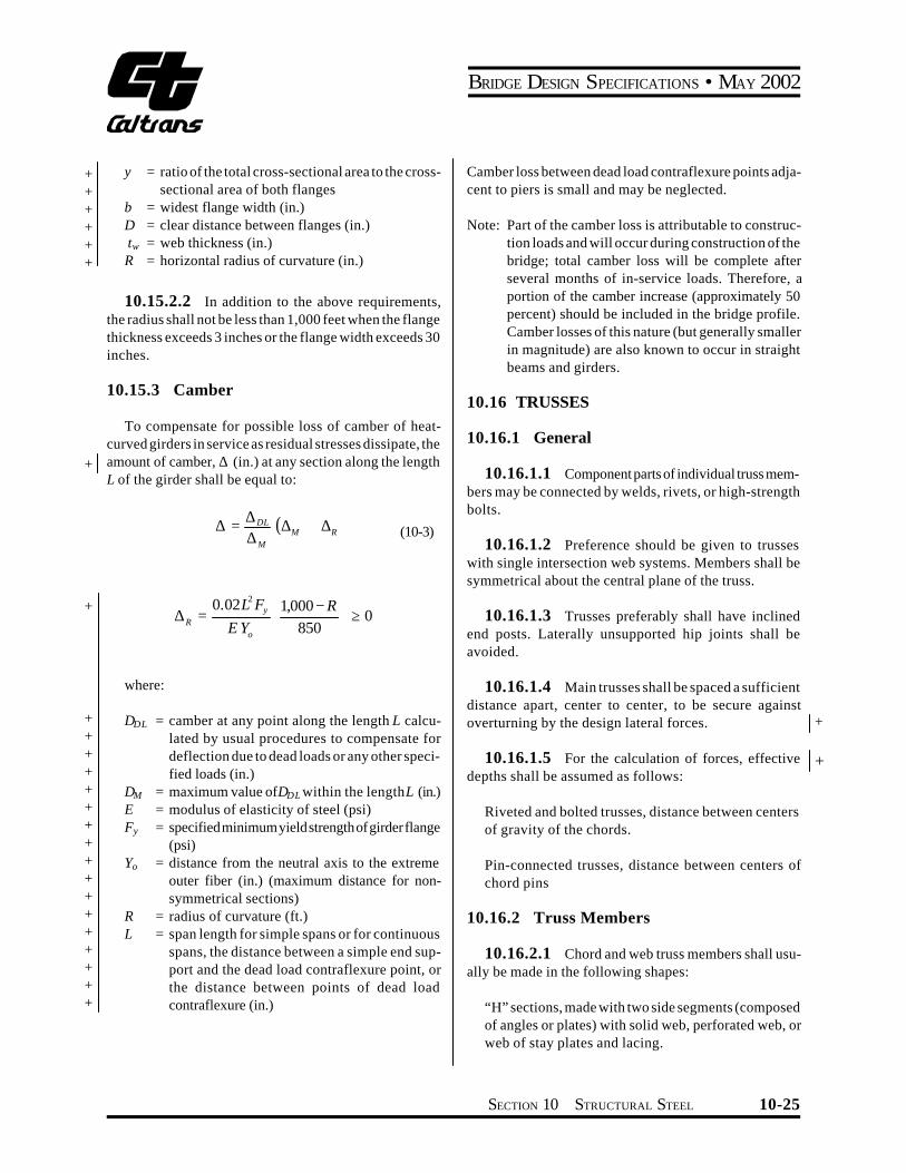
BRIDGE DESIGN SPECIFICATIONS bull MAY 2002
+ + + + + +
+
+
+ + + + + + + + + + + + + + + + +
y = ratio of the total cross-sectional area to the crossshysectional area of both flanges
b = widest flange width (in) D = clear distance between flanges (in) tw = web thickness (in) R = horizontal radius of curvature (in)
101522 In addition to the above requirements the radius shall not be less than 1000 feet when the flange thickness exceeds 3 inches or the flange width exceeds 30 inches
10153 Camber
To compensate for possible loss of camber of heatshycurved girders in service as residual stresses dissipate the amount of camber D (in) at any section along the length L of the girder shall be equal to
DDLD = (DM + DR ) (10-3)DM
002L2 Fy (1000 -R )D = Dagger 0R E Yo Ł 850 ł
where
DDL = camber at any point along the length L calcushylated by usual procedures to compensate for deflection due to dead loads or any other specishyfied loads (in)
DM = maximum value ofDDL within the lengthL (in) E = modulus of elasticity of steel (psi) Fy = specified minimum yield strength of girder flange
(psi) Yo = distance from the neutral axis to the extreme
outer fiber (in) (maximum distance for nonshysymmetrical sections)
R = radius of curvature (ft) L = span length for simple spans or for continuous
spans the distance between a simple end supshyport and the dead load contraflexure point or the distance between points of dead load contraflexure (in)
Camber loss between dead load contraflexure points adjashycent to piers is small and may be neglected
Note Part of the camber loss is attributable to construcshytion loads and will occur during construction of the bridge total camber loss will be complete after several months of in-service loads Therefore a portion of the camber increase (approximately 50 percent) should be included in the bridge profile Camber losses of this nature (but generally smaller in magnitude) are also known to occur in straight beams and girders
1016 TRUSSES
10161 General
101611 Component parts of individual truss memshybers may be connected by welds rivets or high-strength bolts
101612 Preference should be given to trusses with single intersection web systems Members shall be symmetrical about the central plane of the truss
101613 Trusses preferably shall have inclined end posts Laterally unsupported hip joints shall be avoided
101614 Main trusses shall be spaced a sufficient distance apart center to center to be secure against overturning by the design lateral forces +
101615 For the calculation of forces effective depths shall be assumed as follows
+
Riveted and bolted trusses distance between centers of gravity of the chords
Pin-connected trusses distance between centers of chord pins
10162 Truss Members
101621 Chord and web truss members shall usushyally be made in the following shapes
ldquoHrdquo sections made with two side segments (composed of angles or plates) with solid web perforated web or web of stay plates and lacing
SECTION 10 STRUCTURAL STEEL 10-25
BRIDGE DESIGN SPECIFICATIONS bull MAY 2002
+
+ +
Channel sections made with two angle segments with solid web perforated web or web of stay plates and lacing
Single Box sections made with side channels beams angles and plates or side segments of plates only connected top and bottom with perforated plates or stay plates and lacing
Single Box sections made with side channels beams angles and plates only connected at top with solid cover plates and at the bottom with perforated plates or stay plates and lacing
Double Box sections made with side channels beams angles and plates or side segments of plates only connected with a conventional solid web together with top and bottom perforated cover plates or stay plates and lacing
101622 If the shape of the truss permits comshypression chords shall be continuous
101623 In chords composed of angles in channel shaped members the vertical legs of the angles preferably shall extend downward
101624 If web members are subject to reversal of stress their end connections shall not be pinned Counters preferably shall be rigid Adjustable counters if used shall have open turnbuckles and in the design of these members an allowance of 10000 psi shall be made for initial stress Only one set of diagonals in any panel shall be adjustable Sleeve nuts and loop bars shall not be used
10163 Secondary Stresses
The design and details shall be such that secondary stresses will be as small as practicable Secondary stresses due to truss distortion or floor beam deflection usually need not be considered in any member the width of which measured parallel to the plane of distortion is less than one-tenth of its length If the secondary stress exceeds 4000 psi for tension members and 3000 psi for compresshysion members the excess shall be treated as a primary stress Stresses due to the flexural dead load moment of the member shall be considered as additional secondary stress
10164 Diaphragms
101641 There shall be diaphragms in the trusses at the end connections of floor beams
101642 The gusset plates engaging the pedestal pin at the end of the truss shall be connected by a diaphragm Similarly the webs of the pedestal shall if practicable be connected by a diaphragm
101643 There shall be a diaphragm between gusshyset plates engaging main members if the end tie plate is 4 feet or more from the point of intersection of the members
10165 Camber
The length of the truss members shall be such that the camber will be equal to or greater than the deflection produced by the dead load
10166 Working Lines and Gravity Axes
101661 Main members shall be proportioned so that their gravity axes will be as nearly as practicable in the center of the section
101662 In compression members of unsymmetrishycal section such as chord sections formed of side segshyments and a cover plate the gravity axis of the section shall coincide as nearly as practicable with the working line except that eccentricity may be introduced to counteract dead load bending In two-angle bottom chord or diagonal members the working line may be taken as the gage line nearest the back of the angle or at the center of gravity for welded trusses
10167 Portal and Sway Bracing
101671 Through truss spans shall have portal bracing preferably of the two-plane or box type rigidly connected to the end post and the top chord flanges and as deep as the clearance will allow If a single plane portal is used it shall be located preferably in the central transverse plane of the end posts with diaphragms beshytween the webs of the posts to provide for a distribution of the portal stresses The portal bracing shall be designed to take the full end reaction of the top chord lateral system and the end posts shall be designed to transfer this reaction to the truss bearings
10-26 SECTION 10 STRUCTURAL STEEL
BRIDGE DESIGN SPECIFICATIONS bull MAY 2002
101672 Through truss spans shall have sway bracing 5 feet or more deep at each intermediate panel point Top lateral struts shall be at least as deep as the top chord
101673 Deck truss spans shall have sway bracshying in the plane of the end posts and at all intermediate panel points This bracing shall extend the full depth of the trusses below the floor system The end sway bracing
+ shall be proportioned to carry the entire upper lateral load to the supports through the end posts of the truss
10168 Perforated Cover Plates
When perforated cover plates are used the following provisions shall govern their design
101681 The ratio of length in direction of stress to width of perforation shall not exceed two
101682 The clear distance between perforations in the direction of stress shall not be less than the distance between points of support
101683 The clear distance between the end pershyforation and the end of the cover plate shall not be less than 125 times the distance between points of support
101684 The point of support shall be the inner line of fasteners or fillet welds connecting the perforated plate to the flanges For plates butt welded to the flange edge of rolled segments the point of support may be taken as the weld whenever the ratio of the outstanding flange width to flange thickness of the rolled segment is less than seven Otherwise the point of support shall be the root of the flange of the rolled segment
101685 The periphery of the perforation at all points shall have a minimum radius of 112 inches
101686 For thickness of metal see Article 10352
10169 Stay Plates
101691 Where the open sides of compression members are not connected by perforated plates such members shall be provided with lacing bars and shall have stay plates as near each end as practicable Stay plates shall be provided at intermediate points where the lacing is interrupted In main members the length of the end stay
plates between end fasteners shall be not less than 114
times the distance between points of support and the length of intermediate stay plates not less than34 of that distance In lateral struts and other secondary members the overall length of end and intermediate stay plates shall be not less than 34 of the distance between points of support
101692 The point of support shall be the inner line of fasteners or fillet welds connecting the stay plates to the flanges For stay plates butt welded to the flange edge of rolled segment the point of support may be taken as the weld whenever the ratio of outstanding flange width to flange thickness or the rolled segment is less than seven Otherwise the point of support shall be the root of flange of rolled segment When stay plates are butt welded to rolled segments of a member the allowable stress in the member shall be determined in accordance with Article 103 Terminations of butt welds shall be ground smooth
101693 The separate segments of tension memshybers composed of shapes may be connected by perforated plates or by stay plates or end stay plates and lacing End stay plates shall have the same minimum length as specishyfied for end stay plates on main compression members and intermediate stay plates shall have a minimum length of 34 o f that specified for intermediate stay plates on main compression members The clear distance between stay plates on tension members shall not exceed 3 feet
101694 The thickness of stay plates shall be not less than150 of the distance between points of support for main members and 160 of that distance for bracing memshybers Stay plates shall be connected by not less than three fasteners on each side and in members having lacing bars the last fastener in the stay plates preferably shall also pass through the end of the adjacent bar
101610 Lacing Bars
When lacing bars are used the following provisions shall govern their design
1016101 Lacing bars of compression members shall be so spaced that the slenderness ratio of the portion of the flange included between the lacing bar connections will be not more than 40 or more than23 of the slenderness ratio of the member
+
+ + + + +
+ + +
+
SECTION 10 STRUCTURAL STEEL 10-27
BRIDGE DESIGN SPECIFICATIONS bull MAY 2002
1016102 The section of the lacing bars shall be determined by the formula for axial compression in which L is taken as the distance along the bar between its connections to the main segments for single lacing and as 70 percent of that distance for double lacing
1016103 If the distance across the member beshytween fastener lines in the flanges is more than 15 inches and a bar with a single fastener in the connection is used the lacing shall be double and fastened at the intersecshytions
1016104 The angle between the lacing bars and the axis of the member shall be approximately 45 degrees for double lacing and 60 degrees for single lacing
1016105 Lacing bars may be shapes or flat bars For main members the minimum thickness of flat bars shall be 140 of the distance along the bar between its connecshytions for single lacing and 160 for double lacing For bracing members the limits shall be 150 for single lacing and 175 for double lacing
1016106 The diameter of fasteners in lacing bars shall not exceed one-third the width of the bar There shall be at least two fasteners in each end of lacing bars connected to flanges more than 5 inches in width
101611 Gusset Plates
1016111 Gusset or connection plates preferably shall be used for connecting main members except when the members are pin-connected The fasteners connecting each member shall be symmetrical with the axis of the member so far as practicable and the full development of the elements of the member shall be given consideration The gusset plates shall be designed to resist shear axial force and bending moments acting on the weakest or critical section
1016112 Re-entrant cuts except curves made for appearance shall be avoided as far as practicable
1016113 If the length of unsupported edge of a gusset plate exceeds the value of the expression 11000 Fy times its thickness the edge shall be stiffshyened
expression 11000 yF for the following grades of steel
Fy (psi) 11000 yF
36000 58 50000 49 70000 42 90000 37 100000 35
1016114 Listed below are the values of the
101612 Half-Through Truss Spans
1016121 The vertical truss members and the floor beams and their connections in half-through truss spans shall be proportioned to resist a lateral force of not less than 300 pounds per linear foot applied at the top chord panel points of each truss
1016122 The compression chord shall be deshysigned as a compression member with elastic lateral supports at the panel points The strength of the compresshysion chord so determined shall exceed the maximum force from dead load live load and impact in any panel of the compression chord by not less than 50 percent
101613 Fastener Pitch in Ends of Compression Members
In the ends of compression members the pitch of fasteners connecting the component parts of the member shall not exceed four times the diameter of the fastener for a length equal to 112 times the maximum width of the member Beyond this point the pitch shall be increased gradually for a length equal to 112 times the maximum width of the member until the maximum pitch is reached
101614 Net Section of Riveted or High-Strength Bolted Tension Members
1016141 The net section of a riveted or highshystrength bolted tension member is the sum of the net sections of its component parts The net section of a part is the product of the thickness of the part multiplied by its least net width
For a discussion of columns with elastic lateral supports refer to Timoshenko amp Gere ldquoTheory of Elastic Stabilityrdquo McGraw-Hill Book Co Second Edition P70
+ + + + + + +
+ + +
+
10-28 SECTION 10 STRUCTURAL STEEL
BRIDGE DESIGN SPECIFICATIONS bull MAY 2002
1016142 The net width for any chain of holes extending progressively across the part shall be obtained by deducting from the gross width the sum of the diamshyeters of all the holes in the chain and adding for each gage space in the chain the quantity
2s+ (10-4)4g
where
+ s = pitch of any two successive holes in the chain + (in) + g = gage of the same holes (in)
The net section of the part is obtained from the chain that gives the least net width
1016143 For angles the gross width shall be the sum of the widths of the legs less the thickness The gage for holes in opposite legs shall be the sum of gages from back of angle less the thickness
1016144 At a splice the total force in the member+ + being spliced is transferred by fasteners to the splice
material
1016145 When determining the stress on any least net width of either splice material or member being spliced
+
+
the amount of the force previously transferred by fastenshyers adjacent to the section being investigated shall be
+ considered in determining the stress on the net section
1016146 The diameter of the hole shall be taken as 18 inch greater than the nominal diameter of the rivet or high-strength bolt unless larger holes are permitted in accordance with Article 1024
1017 BENTS AND TOWERS
10171 General
Bents preferably shall be composed of two supporting columns and the bents usually shall be united in pairs to form towers The design of members for bents and towers is governed by applicable articles
10172 Single Bents
Single bents shall have hinged ends or else shall be designed to resist bending
10173 Batter
Bents preferably shall have a sufficient spread at the base to prevent uplift under the design lateral loadings In general the width of a bent at its base shall be not less than one-third of its height
10174 Bracing
101741 Towers shall be braced both transversely and longitudinally with stiff members having either welded high-strength bolted or riveted connections The sections of members of longitudinal bracing in each panel shall not be less than those of the members in corresponding panels of the transverse bracing
101742 The bracing of long columns shall be designed to fix the column about both axes at or near the same point
101743 Horizontal diagonal bracing shall be placed in all towers having more than two vertical panels at alternate intermediate panel points
10175 Bottom Struts
The bottom struts of towers shall be strong enough to slide the movable shoes with the structure unloaded the coefficient of friction being assumed at 025 Provision for expansion of the tower bracing shall be made in the column bearings
1018 SPLICES
10181 General
101811 Design Strength
Splices may be made by rivets by high-strength bolts or by the use of welding In general splices whether in tension compression bending or shear shall be deshysigned in the cases of the service load design or the strength design methods for a capacity based on not less than 100 percent of the allowable design strength in the
+
+ + + + + +
SECTION 10 STRUCTURAL STEEL 10-29
BRIDGE DESIGN SPECIFICATIONS bull MAY 2002
+ member taking into account the bolt holes Bolted and + riveted splices in flexural members shall satisfy the requireshy+ ments of Article 10182 Bolted and riveted splices in + compression members shall satisfy the requirements of + Article 10183 Bolted and riveted splices in tension memshy+ bers shall satisfy the requirements of Article 10184 + Bolted and riveted splices in tension members shall also + satisfy the requirements of Article 10194 Welded splices + shall satisfy the requirements of Article 10185 Where a + section changes at a splice the small section is to be used + to satisfy the above splice requirements
101812 Fillers
1018121 For fillers 14 inch and thicker in bolted or riveted axially loaded connections including girder flange splices additional fasteners shall be required to distribute the total stress in the member uniformly over the combined section of the member and the filler The filler shall either
+ be extended beyond the splice material and secured by + additional fasteners or as an alternate to extending the + filler an equivalent number of fasteners may be included + in the connection Fillers 14 inch and thicker need not be + extended and developed provided that the design shear + strength of the fasteners specified in Article 1056132 in
the case of the strength design method and in the Tables 10323A and 10323B in the case of the service load design method is reduced by the following factor R
R=[(1+g)(1+2g)] (10-4a)
where g=Af Ap
+ Af = sum of the area of the fillers on the top and + bottom of the connected plate (in2) + +
Ap = smaller of either the connected plate area or the sum of the splice plate areas on the top and
+ bottom of the connected plate (in2)
+ The design slip force specified in Article 1056132 in + the case of the strength design method and in Article
1032321 in the case of the service load design method for slip-critical connections shall not be adjusted for the effect of the fillers Fillers 14 inch or more in thickness shall consist of not more than two plates unless special permisshysion is given by the Engineer
1018122 For bolted web splices with thickness differences of 116 inch or less no filler plates are required
1018123 Fillers for welded splices shall conform to the requirements of the AISIAASHTOAWS D15 Bridge Welding Code
101813 Design Force for Flange Splice Plates
For a flange splice with inner and outer splice plates the flange design force may be assumed to be divided equally to the inner and outer plates and their connections when the areas of the inner and outer plates do not differ by more than 10 percent When the areas of the inner and outer plates differ by more than 10 percent the design force in each splice plate and its connection shall be determined by multiplying the flange design force by the ratio of the area of the splice plate under consideration to the total area of the inner and outer splice plates For this case the shear strength of the connection shall be checked for the maximum calculated splice plate force acting on a single shear plane The slip resistance of high-strength bolted connections for a flange splice with inner and outer splice plates shall always be checked for the flange design force divided equally to the two slip planes
101814 Truss Chords and Columns
Splices in truss chords and columns shall be located as near to the panel points as practicable and usually on the side where smaller stress occurs The arrangement of plates angles or other splice elements shall be such as to make proper provision for the stresses both axial and bending in the component parts of the member spliced
10182 Flexural Member
101821 General
1018211 Splices shall preferably be made at or near points of dead load contraflexure in continuous spans and at points of the section change
1018212 In both flange and web splices there shall be not less than two rows of bolts on each side of the joint
1018213 Oversize or slotted holes shall not be used in either the member or the splice plates at the bolted splices
1018214 In both flange and web splices highshystrength bolted connections shall be proportioned to prevent slip during erection of the steel and during the casting or placing of the deck
+ + +
10-30 SECTION 10 STRUCTURAL STEEL
BRIDGE DESIGN SPECIFICATIONS bull MAY 2002
+
+ + +
+ +
+
+
+ + + + + + + +
+ +
+ +
+
+ + + + +
+
1018215 Deleted
1018216 Flange and web splices in areas of stress reversal shall be checked for both positive and negative flexure
1018217 Riveted and bolted flange angle splices shall include two angles one on each side of the flexural member
101822 Flange Splices
1018221 For checking the strength of flange splices an effective area A shall be used for the flanges and forethe individual splice plates as follows
For flanges and their splice plates subject to tension
Ae= wnt + b Ag pound Ag (10-4b)
where
Wn = least net width of the flange or splice plate computed as specified in Article101614 (in)
t = flange or splice plate thickness (in) Ag = gross area of the flange or splice plate (in2) b = 00 for M 270 Grade 100100W steels or when
holes exceed 1 14 inch in diameter = 015 for all other steels and when holes are less
than or equal to 1 14 inch in diameter
The diameter of the holes shall be taken as specified in Article 1016146
For the flanges and their splice plates subject to compression
Ae = Ag (10-4c)
1018222 In the case of the strength design method the splice plates shall be proportioned for a design force P equal to a design stressF times the smaller effectivecu cuarea A on either side of the splice F is defined ase cufollows
Fcu =a Fyf (10-4d)
where a = 10 except that a lower value equal to (MuMy) may
be used for flanges in compression at sections where Mu is less than My
Mu = design bending strength of the section in posishytive or negative flexure at the point of splice whichever causes the maximum compressive stress due to the factored loads at the mid-thickshyness of the flange under consideration (lb-in)
My = moment capacity at first yield for the section at the point of splice used to compute Mu (lb-in) For composite sectionsMy shall be calculated in accordance with Article1050(c) For hybrid secshytions My shall be computed in accordance with Article 1053
Fyf = specified minimum yield strength of the flange (psi)
In calculating Mu and My holes in the flange subject to tension shall be accounted for as specified in Article 1012 For a flange splice with inner and outer splice plates the flange design forces shall be proportioned to the inner and outer plates and their connections as specified in Article 101813 The effective area Ae of each splice plate shall be sufficient to prevent yielding of the splice plate under its calculated portion of the design force As a minimum the connections for both the top and bottom flange splices shall be proportioned to develop the design force in the flange through shear in the bolts and bearing at the bolt holes as specified in Article 1056132 Where filler plates are required the requirements of Article 1018121 shall also be satisfied
As a minimum high-strength bolted connection for both top and bottom flange splices shall be proportioned to prevent slip at an overload design forcePfo defined as follows
Pfo=permilfo RpermilAg (10-4e)
where
fo = maximum flexural stress due to Group I loading divided by 13 at the mid-thickness of the flange under consideration for the smaller section at the point of splice (psi)
R = reduction factor for hybrid girders specified in Article 105312 R shall be taken equal to 10 when fo is less than or equal to the specified minimum yield strength of the web Fyw For homogeneous girders R shall always be taken equal to 10
+ +
+
+ + + +
SECTION 10 STRUCTURAL STEEL 10-31
BRIDGE DESIGN SPECIFICATIONS bull MAY 2002
+ +
+ + + +
+
+ +
+
Ag = smaller gross flange area on either side of the splice (in2)
fo andR shall be computed using the gross section of the member The slip resistance of the connection shall be computed from Equation (10-172)
1018223 In the case of the service load design method the splice plates shall be proportioned for a design force Pcf equal to the allowable flexural stress for the flange under consideration at the point of splice Fb times the smaller effective area A on either side of theesplice
For a flange splice with inner and outer splice plates the flange design forces shall be proportioned to the inner and outer plates and their connections as specified in Article 101813 The effective area Ae of each splice plate shall be sufficient to ensure that the stress in the splice plate does not exceed the allowable flexural stress under its calculated portion of the design force As a minimum the connections for both the top and bottom flange splices shall be proportioned to develop the design force in the flange through shear in the bolts and bearing at the bolt holes as specified in Table 10323B Where filler plates are required the requirements of Article 1018121 shall also be satisfied
As a minimum high-strength bolted connection for both top and bottom flange splices shall be proportioned to prevent slip at a force equal to the flange design stress times the smaller value of the gross flange area on either side of the splice The slip resistance of the connection shall be determined as specified in Article 1032321
1018224 (Deleted)
101823 Web Splices
1018231 In general web splice plates and their connections shall be proportioned for shear a moment due to eccentricity of the shear at the point of splice and a portion of the flexural moment that is assumed to be resisted by the web at the point of splice Webs shall be spliced symmetrically by plates on each side The web splice plates shall extend as near as practical for the full depth between flanges
1018232 In the case of the strength design method web splice plates and their connections shall be proporshytioned for a design shear V equal to the shear capacitywuof the smaller web at the point of splice V u
1018233 In the case of the strength design method web splice plates and their connections shall be proporshytioned for a design momentMvu due to the eccentricity of the design shear at the point of splice defined as follows
Mvu=Vwue (10-4f)
where
Vwu = design shear in the web at the point of splice defined in Article 1018232 (lb)
e = distance from the centerline of the splice to the centroid of the connection on the side of the joint under consideration (in)
1018234 In the case of the strength design method web splice plates and their connections shall be proporshytioned for a design momentM representing the portionwuof the flexural moment that is assumed to be resisted by the web M shall be applied at the mid-depth of the web Forwusections where the neutral axis is not located at mid-depth of the web a horizontal design force resultant in the web at the point of splice H shall also be applied at the midshywudepth of the web M and H may be computed aswu wufollows
For non-compact sections
wu M = 2
12 wt D ( cr RF yfF+ ) (10-4g)
wu H = (2
w yf
t D F )crRF- (10-4h)
For compact sections
wu M = 4
w ywt F ( 2D )24 cy- (10-4i)
wu H 2 w o ywt y F= (10-4j)
+ + + +
+
+
+ +
+ +
+
+
+
+
+
+
+
+
10-32 SECTION 10 STRUCTURAL STEEL
BRIDGE DESIGN SPECIFICATIONS bull MAY 2002
+
+ + + + + + + + + + + + +
+ + + +
+
+
+
+
+
where
Fcr = design flexural strength specified in Articles 105012 and 105022 for composite sections or determined by MuSxcRb where Mu is defined as in Articles 10482 10483 10484 for noncomposite sections (psi)
Fyf = specified minimum yield strength of the flange (psi)
Fyw =specified minimum yield strength of the web (psi) yo = distance form the mid-depth of the web to the
plastic neutral axis (in) D = clear unsupported distance between flange comshy
ponents (in) tw = web thickness (in)
1018235 In the case of the strength design method web splice plates and their connections shall be proporshytioned for the most critical combination of V M M wu vu wuand H The connections shall be proportioned as eccenshywutrically loaded connections to resist the resultant design force through shear in the bolts and bearing at the bolt holes as specified in Article 1056132 In addition as a minimum high-strength bolted connections for web splices shall be proportioned as eccentrically loaded connections to prevent slip under the most critical combination of 1) an overload design shear V 2) an overload designwomoment M due to the eccentricity of the overloadvodesign shear 3) an overload design momentM appliedwoat mid-depth of the web representing the portion of the flexural moment that is assumed to be resisted by the web and 4) for sections where the neutral axis is not located at mid-depth of the web an overload horizontal design force H applied at mid-depth of the web as followswo
Vwo = Vo (10-4k)
Mvo = Vwoe (10-4l)
where
Vo = maximum shear in the web due to Group I loading divided by 13 at the point of splice (lb)
Mwo and Hwo may be determined as follows
t D2 wMwo = (10-4m)fo - fof12
t DwHw = 2 ( fo - fof ) (10-4n)
where
fo = maximum flexural stress due to Group I loading divided by 13 at the mid-thickness of the flange under consideration for smaller section at the point of splice (positive for tension negative for compression) (psi)
fof = flexural stress due to Group I loading divided by 13 at the mid-thickness of the other flange at the point of splice concurrent with fo in the flange under consideration (positive for tension negashytive for compression) (psi)
fo and fof shall be computed using the gross section of the member The maximum resultant force on the eccentrically loaded connection shall not exceed the slip resistance computed from Equation (10-172) with Nb taken equal to 10
1018236 In the case of the service load design method web splice plates and their connections shall be proportioned for a design shear stress in the web at the point of splice Fw equal to the allowable shear stress in the web at the point of splice Fv
1018237 In the case of the service load design method web splice plates and their connections shall be proportioned for a design moment Mv due to the eccentricity of the design shear at the point of splice defined as follows
Mv = FwDtwe (10-4o)
where
Fw = design shear stress in the web at the point of splice defined in Article 1018236 (psi)
D =web depth (in) tw = web thickness (in)
1018238 In the case of the service design method web splice plates and their connections shall be proporshytioned for a design moment Mw representing the portion of the flexural moment that is assumed to be resisted by the web Mw shall be applied at the mid-depth of the web For sections where the neutral axis is not located at mid-depth of the web a horizontal design force resultant in the web at the point of splice Hw shall also be applied at the midshydepth of the webMw andHw may be computed as follows
t D2 wM = ( RF + F ) (10-4p)w bc bt12
+ +
+ + + +
+
+ + + +
+
+
SECTION 10 STRUCTURAL STEEL 10-33
Note (b) deleted +
BRIDGE DESIGN SPECIFICATIONS bull MAY 2002
+
+ + + +
+
+ +
wH = t D (F - RF ) (10-4q)w bt bc2
where
= allowable compression flange stress specifiedFbc in Table 10321A (psi)
= allowable tension flange stress specified inFbt Table 10321A (psi)
1018239 In the case of the service load design method web splice plates and their connections shall be proportioned for the most critical combination of F Dt w wM M andH The connections shall be proportioned asv w weccentrically loaded connections to resist the resultant design force through shear in the bolts and bearing at the bolt holes as specified in Table 10323B In addition as a minimum high-strength bolted connections for web splices shall be proportioned as eccentrically loaded conshynections to prevent slip under the most critical combinashytion of F Dt M M and H M and H shall bew w v w w w wcomputed using the gross section of the member The
FIGURE 10185A
maximum resultant force on the eccentrically loaded conshynection shall not exceed the slip resistance computed from Table 1032321 with Nb taken equal to 10
10183 Compression Members
Compression members such as columns and chords shall have ends in close contact at riveted and bolted splices Splices of such members which will be fabricated and erected with close inspection and detailed with milled ends in full contact bearing at the splices may be held in place by means of splice plates and rivets or high-strength bolts proportioned for not less than 50 percent of the lower allowable design strength of sections spliced The strength of compression members connected by high-strength bolts or rivets shall be determined using the gross section
10184 Tension Members
The tension strength of splice components shall be based on Article 10123 For calculating the net section the provisions of Articles 109 and 101614 shall apply
Splice Details
+ + +
10-34 SECTION 10 STRUCTURAL STEEL
BRIDGE DESIGN SPECIFICATIONS bull MAY 2002
+
+ + + +
+ +
As a minimum in the case of the strength design method high-strength bolted connections for splices in tension members shall be proportioned to prevent slip at an overload design forcePo equal to the maximum tensile stress in the member due to Group I loading divided by 13 times the gross section of member The slip resistance shall be computed from Equation (10-172) In the case of the service load design method high-strength bolted connections shall be proportioned to prevent slip at a force equal to the allowable design strength specified in Article 101811 times the gross area of the member The slip resistance of the connection shall be determined as specified in Article 1032321
10185 Welding Splices
101851 Tension and compression members may be spliced by means of full penetration butt welds prefershyably without the use of splice plates
101852 Splices shall not be welded in field
101853 Material of different widths spliced by butt welds shall have transitions conforming to Figure 10185A At butt weld splices joining material of different thicknesses there shall be a uniform slope between the offset surfaces of not more than 1 in 2 12 with respect to the surface of either part
10191 General
101911 Except as otherwise provided herein conshynections for main members shall be designed in the cases of the service load design and the strength design methshyods for a capacity based on not less than 100 percent of the allowable design strength in the member
101912 Connections shall be made symmetrical about the axis of the members insofar as practicable Connecshytions except for lacing bars and handrails shall contain not less than two fasteners or equivalent weld
101913 Members including bracing preferably shall be so connected that their gravity axes will intersect in a point Eccentric connections shall be avoided if practishycable but if unavoidable the members shall be so proporshytioned that the combined forces will not exceed the allowshyable design strength
101914 In the case of connections which transfer total member shear at the end of the member the gross section shall be taken as the gross section of the conshynected elements
10192 End Connections of Floor Beams and Stringers
101921 The end connection shall be designed for calculated member loads The end connection angles of floor beams and stringers shall be not less than38 inch in finished thickness Except in cases of special end floor beam details each end connection for floor beams and stringers shall be made with two angles The length of these angles shall be as great as the flanges will permit Bracket or shelf angles which may be used to furnish support during erection shall not be considered in detershymining the number of fasteners required to transmit end shear
101922 End connection details shall be designed with special care to provide clearance for making the field connection
101923 End connections of stringers and floor beams preferably shall be bolted with high-strength bolts however they may be riveted or welded In the case of welded end connections they shall be designed for the vertical loads and the end bending moment resulting from the deflection of the members
101924 Where timber stringers frame into steel floor beams shelf angles with stiffeners shall be provided to carry the total reaction Shelf angles shall be not less than 716 inch thick
10193 End Connections of Diaphragms and Cross Frames
101931 The end connections for diaphragms or cross frames in straight rolled-beam and plate girder bridges shall be designed for the calculated member loads
101932 Vertical connection plates such as transshyverse stiffeners which connect diaphragms or cross frames to the beam or girder shall be rigidly connected to both top and bottom flanges
SECTION 10 STRUCTURAL STEEL 10-35
BRIDGE DESIGN SPECIFICATIONS bull MAY 2002
+ 10194 Block Shear Rupture Strength
+ 101941 General
+ Block shear rupture is one of several possible failure + modes for splices connections gusset plates and tension + members Block shear rupture failure is developed when + the net section of one segment ruptures and the gross + section of a perpendicular segment yields The web + connections of coped beams all tension connections + including connection plates splice plates and gusset + plates and tension members shall be investigated to + ensure that the adequate block shear rupture strength is + provided
+ 101942 Allowable Block Shear Rupture + Stress
+ In the Service Load Design Method calculated tension + stress based on the gross section shall not exceed the + allowable block shear rupture stress obtained from the + following equations
+ for vntn AA Dagger 06
+ ( ) gtnuvgybs AF AF AF 055033 += (10-4a)
+ for vntn AA lt 06
+ ( ) gtgyvnubs AF AF AF 055033 += (10-4b)
+ where
+ Ag = gross area of whole connected material (in2) + Avg = gross area along the plane resisting shear (in2) + Avn = net area along the plane resisting shear (in2) + Atg = gross area along the plane resisting tension (in2) + Atn = net area along the plane resisting tension (in2) + Fy = specified minimum yield strength of the conshy+ nected materials (psi) + Fu = specified minimum tensile strength of the conshy+ nected materials (psi) + Fbs = allowable block shear rupture stress (psi)
101943 Design Block Shear Rupture + Strength +
In the Strength Design Method calculated tension + force shall not exceed the design block shear rupture + strength obtained from the following equations +
+ for vntn AA Dagger 058 +
( tn )uvgybsbs F AF AT += 058f (10-4c)
for vntn AA lt 058
( tg )yvnubsbs F AF AT += 058f (10-4d)
where Tbs = design block shear rupture strength (lb) f bs = 08 reduction factor for block shear rupture
strength
1020 DIAPHRAGMS AND CROSS FRAMES
10201 General
Rolled beam and plate girder spans shall be provided with cross frames or diaphragms at each support and with + cross frames or diaphragms placed in all bays and spaced at intervals not to exceed 25 feet Diaphragms for rolled beams shall be at least13 and preferably12 the beam depth and for plate girders shall be at least 12 and preferably 34 the girder depth Cross frames shall be as deep as + practicable Cross frames shall preferably be of the cross type or vee type End cross frames or diaphragms shall be proportioned to adequately transmit all the lateral forces to the bearings Intermediate cross frames shall be normal + to the main beams and girders when the supports are skewed more than twenty degrees (20deg) Cross frames on horizontally curved steel girder bridges shall be designed as main members with adequate provisions for transfer of lateral forces from the girder flanges Cross frames and diaphragms shall be designed for horizontal wind loads as described in Article 10212 seismic loads and other applishy + cable loads +
10-36 SECTION 10 STRUCTURAL STEEL
BRIDGE DESIGN SPECIFICATIONS bull MAY 2002
+ 10202 Horizontal Force
+ The maximum horizontal force FD (lb) in the transshyverse diaphragms and cross frames is obtained from the following
+ FD = 114WSd (10-5)
+ where + W = wind load along the exterior flange (lbft) + Sd = diaphragm spacing (ft)
+ 102021 Deleted
+ 102022 Deleted
+ 10203 Deleted
+ 1021 LATERAL BRACING
10211 The need for lateral bracing shall be investigated + for wind loads seismic loads and other applicable lateral + loads Flanges attached to concrete decks or other decks
of comparable rigidity will not require lateral bracing
10212 A horizontal wind force of 50 pounds per square foot shall be applied to the area of the superstructure exposed in elevation Half this force shall be applied in the
+ plane of each flange The maximum induced stresses f + (psi) in the bottom flange of each girder in the system + when top flanges are continuously supported can be + computed from the following
+ cbR ff = (10-6)
+ [ ] ł
)
Ł
(-= -
bracing is provided when no bottomlateral
1102272 2 3SdLR
(10-7)
+ [ ] ł
)
Ł
(-= -
bracingis provided whenbottomlateral
0640059 1 2SdLR
(10-8)
+ 2
72
ff
cb cb t b
Mf = (10-9)
+ 2008 dcb W SM = (10-10)
L = span length (ft) tf = thickness of flange (in) + bf = width of flange (in) +
The stresses in flanges of each girder in the system + when top flanges are not continuously supported shall be + computed using the structural system in the plane of the + flanges under consideration The allowable stress shall be + factored in accordance with Article 322
10213 When required lateral bracing shall be placed in the exterior bays between diaphragms or cross frames All required lateral bracing shall be placed in or near the plane of the flange being braced
10214 Where beams or girders comprise the main members of through spans such members shall be stiffened against lateral deformation by means of gusset plates or knee braces with solid webs which shall be connected to the stiffeners on the main members and the floor beams If the unsupported length of the edge of the gusset plate (or solid web) exceeds 60 times its thickness the plate or web shall have a stiffening plate or angles connected along its unsupported edge
10215 Through truss spans deck truss spans and spandrel braced arches shall have top and bottom lateral bracing
10216 Bracing shall be composed of angles other shapes or welded sections The smallest angle used in bracing shall be 3 by 212 inches There shall be not less than 2 fasteners or equivalent weld in each end connection of the angles
10217 If a double system of bracing is used both systems may be considered effective simultaneously if the members meet the requirements both as tension and compression members The members shall be connected at their intersections
10218 The lateral bracing of compression chords preferably shall be as deep as the chords and effectively connected to both flanges
1022 CLOSED SECTIONS AND POCKETS
10221 Closed sections and pockets or depressions that will retain water shall be avoided where practicable
SECTION 10 STRUCTURAL STEEL 10-37
BRIDGE DESIGN SPECIFICATIONS bull MAY 2002
+ +
+ + + + +
Pockets shall be provided with effective drain holes or be filled with waterproofing material
10222 Details shall be so arranged that the destructive effects of bird life and the retention of dirt leaves and other foreign matter will be reduced to a minimum Where angles are used either singly or in pairs they preferably shall be placed with the vertical legs extending downward Structural tees preferably shall have the web extending downward
1023 WELDING
10231 General
102311 Steel base metal to be welded weld metal and welding design details shall conform to the requireshyments of the ANSIAASHTOAWS D15 Bridge Welding Code and the current Standard Specifications of the California Department of Transportation
102312 Welding symbols shall conform with the latest edition of the American Welding Society Publicashytion AWS A24
102313 Fabrication shall conform to the Stanshydard Specifications of the California Department of Transshyportation For fracture critical members see the AASHTO ldquoGuide Specifications for Fracture Critical Non-Redunshydant Steel Bridge Membersrdquo
10232 Effective Size of Fillet Welds
102321 Maximum Size of Fillet Welds
The maximum size of a fillet weld that may be assumed in the design of a connection shall be such that the stresses in the adjacent base material do not exceed the values allowed in Article 1032 The maximum size that may be used along edges of connected parts shall be
(1) Along edges of material less than14 inch thick the maximum size may be equal to the thickness of the material
(2) Along edges of material 14 inch or more in thickshyness the maximum size shall be 116 inch less than the thickness of the material unless the weld is especially designated on the drawings to be built out to obtain full throat thickness
102322 Minimum Size of Fillet Welds
The minimum fillet weld size shall be as shown in the following table
Base Metal Thickness of Minimum Size Thicker Part of Fillet Weld Jointed (T) in mm in mm
T pound 34 T pound 190 14 6 Single-pass WeldsT gt 34 Tgt 190 516 8 must be used
Except that the weld size need not exceed the thickness of the thinner part jointed For this exception particular care should be taken to provide sufficient preheat to ensure weld soundness
Smaller fillet welds may be approved by the Engineer based upon applied stress and the use of appropriate preheat
10233 Minimum Effective Length of Fillet Welds
The minimum effective length of a fillet weld shall be four times its size and in no case less than 112 inches
10234 Fillet Weld End Returns
Fillet welds which support a tensile force that is not parallel to the axis of the weld or which are proportioned to withstand repeated stress shall not terminate at corners of parts or members but shall be returned continuously full size around the corner for a length equal to twice the weld size where such return can be made in the same plane End returns shall be indicated on design and detail drawshyings
10235 Seal Welds
Seal welding shall preferably be accomplished by a continuous weld combining the functions of sealing and strength changing section only as the required strength or the requirements of minimum size fillet weld based on material thickness may necessitate
10-38 SECTION 10 STRUCTURAL STEEL
BRIDGE DESIGN SPECIFICATIONS bull MAY 2002
+
+ + + + + + +
+
+ + + + + + + + + + +
+ +
1024 FASTENERS
10241 General
102411 In proportioning fasteners for shear and tension the cross-sectional area based upon the nominal diameter shall be used Galvanization of AASHTO M253 (ASTM A490) and A354 Grade BD high strength bolts is not permitted due to hydrogen embrittlement problems These fasteners must be carefully evaluated before being utilized Requirements for bolts in these specifications shall be used for threaded rods threaded studs and anchor rods where applicable
102412 High-strength bolts may be substituted for Grade 1 rivets (ASTM A 502) or ASTM A307 bolts When AASHTO M 164 (ASTM A325) high-strength bolts are substituted for ASTM A307 bolts they shall be tightened to the full effort of a man using an ordinary spud wrench
102413 All bolts except high-strength bolts tensioned to the requirements of the Standard Specificashytions of the California Department of Transportation shall have single self-locking nut double nuts or a nut with a thread locking system (anaerobic adhesive) to prevent nut loosening The thread locking system is the preferred method for bolt diameters of one inch or less The thread locking system shall not be used on bolt diameters greater than one inch When using the double nut method a torque value for the jam nut relative to the main nut shall be shown on the plans to assure that a reasonable effort will be made to lock the two nuts together
102414 Joints required to resist shear between their connected parts are designated as either slip-critical or bearing-type connections Slip-critical joints are reshyquired for joints subject to stress reversal heavy impact loads severe vibration or where stress and strain due to joint slippage would be detrimental to the serviceability of the structure They include
(1) Joints subject to fatigue loading (2) Joints with bolts installed in oversized holes (3) Except where the Engineer intends otherwise and
so indicates in the contract documents joints with bolts installed in slotted holes where the force on the joint is in a direction other than normal (beshytween approximately 80 and 100 degrees) to the axis of the slot
(4) Joints subject to significant load reversal (5) Joints in which welds and bolts share in transmitshy
ting load at a common faying surface (6) Joints in which in the judgment of the Engineer
any slip would be critical to the performance of the joint or the structure and so designated on the contract plans and specifications
102415 High-strength bolted connections subshyject to tension or combined shear and tension shall be designed as slip-critical connections
102416 Bolted bearing-type connections using high-strength bolts shall be limited to members in comshypression and secondary members
102417 The effective bearing area of a fastener shall be its diameter multiplied by the thickness of the metal on which it bears In metal less than 38 inch thick counshytersunk fasteners shall not be assumed to carry stress In metal 38 inch thick and over one-half the depth of counshytersink shall be omitted in calculating the bearing area
102418 In determining whether the bolt threads are excluded from the shear planes of the contact surfaces thread length of bolts shall be calculated as two thread pitches greater than the specified thread length as an allowance for thread run out
102419 In bearing-type connections pull-out shear in a plate should be investigated between the end of the plate and the end row of fasteners (See Table 10323B footnote h or Article 105613)
+ +
SECTION 10 STRUCTURAL STEEL 10-39
5
BRIDGE DESIGN SPECIFICATIONS bull MAY 2002
+
TABLE 10242 Nominal Hole Dimension
Hole Dimension (in)Bolt
Standard Oversize Short Slot Long SlotDiameter (in) (Diameter) (Diameter) (Width x Length) (Width x Length)
1116 1316
58 1116 x 78
1116 x 1916
34 1316
1516 1316 x 1 1316 x 178
78 1516 1116
15 16 x 118 1516 x 2316
11 41 1116 1116 x 1516 1116 x 212
(d + 116) x (d + 38) (d + 116) x (25 x d)Dagger 118 d + 116 d + 516
10242 Hole Types 100 degrees) to the axis of the slot Long slotted holes may
Hole types for high-strength bolted connections are be used in one of the connected parts at any individual standard holes oversize holes short slotted holes and faying surface without regard for the direction of applied long slotted holes The nominal dimensions for each type load on connections which satisfy the requirements of hole shall be not greater than those shown in Table 10242 Article 1032321 or Article 105731 as applicable
10243 Washer Requirements102421 In the absence of approval by the Engishyneer for use of other hole types standard holes shall be used in high-strength bolted connections Design details shall provide for washers in highshy
strength bolted connections as follows 102422 When approved by the Engineer overshy
size short slotted hole or long slotted holes may be used 102431 Where the outer face of the bolted parts subject to the following joint detail requirements has slope greater than 120 with respect to a plane normal
to the bolt axis a hardened beveled washer shall be used to compensate for the lack of parallelism Beveled washers
of connections which satisfy the requirements of Article 1024221 Oversize holes may be used in all plies
other than the standard 16 slope shall be detailed in the plans
shall not be used in bearing-type connections 1032321 or Article 10573 as applicable Oversize holes
102432 Hardened washers are not required for connections using AASHTO M164 (ASTM A325) and
or all plies of high-strength bolted connections designed 1024222 Short slotted holes may be used in any
AASHTO M253 (ASTM A490) bolts except as required in on the basis of Table 10323B or Table 1056A as appli- Articles 102433 through 102437 cable provided the load is applied approximately normal (between 80 and 100 degrees) to the axis of the slot Short 102433 Hardened washers shall be used under slotted holes may be used without regard for the direction the element turned in tightening and to cover oversize or of applied load in any or all plies of connections which short slotted holes in the outer ply satisfy the requirements of Article 1032321 or Article 105731 as applicable 102434 Irrespective of the tightening method
hardened washers shall be used under both the head and the nut when AASHTO M253 (ASTM A490) bolts are to
of the connected parts at any individual faying surface in 1024223 Long slotted holes may be used in one
be installed in material having a specified yield strength high-strength bolted connections designed on the basis less than 40000 psi of Table 10323B or Table 1056A as applicable provided the load is applied approximately normal (between 80 and
+ +
+ + +
+ +
+ + +
10-40 SECTION 10 STRUCTURAL STEEL
BRIDGE DESIGN SPECIFICATIONS bull MAY 2002
+
+ +
Channel sections made with two angle segments with solid web perforated web or web of stay plates and lacing
Single Box sections made with side channels beams angles and plates or side segments of plates only connected top and bottom with perforated plates or stay plates and lacing
Single Box sections made with side channels beams angles and plates only connected at top with solid cover plates and at the bottom with perforated plates or stay plates and lacing
Double Box sections made with side channels beams angles and plates or side segments of plates only connected with a conventional solid web together with top and bottom perforated cover plates or stay plates and lacing
101622 If the shape of the truss permits comshypression chords shall be continuous
101623 In chords composed of angles in channel shaped members the vertical legs of the angles preferably shall extend downward
101624 If web members are subject to reversal of stress their end connections shall not be pinned Counters preferably shall be rigid Adjustable counters if used shall have open turnbuckles and in the design of these members an allowance of 10000 psi shall be made for initial stress Only one set of diagonals in any panel shall be adjustable Sleeve nuts and loop bars shall not be used
10163 Secondary Stresses
The design and details shall be such that secondary stresses will be as small as practicable Secondary stresses due to truss distortion or floor beam deflection usually need not be considered in any member the width of which measured parallel to the plane of distortion is less than one-tenth of its length If the secondary stress exceeds 4000 psi for tension members and 3000 psi for compresshysion members the excess shall be treated as a primary stress Stresses due to the flexural dead load moment of the member shall be considered as additional secondary stress
10164 Diaphragms
101641 There shall be diaphragms in the trusses at the end connections of floor beams
101642 The gusset plates engaging the pedestal pin at the end of the truss shall be connected by a diaphragm Similarly the webs of the pedestal shall if practicable be connected by a diaphragm
101643 There shall be a diaphragm between gusshyset plates engaging main members if the end tie plate is 4 feet or more from the point of intersection of the members
10165 Camber
The length of the truss members shall be such that the camber will be equal to or greater than the deflection produced by the dead load
10166 Working Lines and Gravity Axes
101661 Main members shall be proportioned so that their gravity axes will be as nearly as practicable in the center of the section
101662 In compression members of unsymmetrishycal section such as chord sections formed of side segshyments and a cover plate the gravity axis of the section shall coincide as nearly as practicable with the working line except that eccentricity may be introduced to counteract dead load bending In two-angle bottom chord or diagonal members the working line may be taken as the gage line nearest the back of the angle or at the center of gravity for welded trusses
10167 Portal and Sway Bracing
101671 Through truss spans shall have portal bracing preferably of the two-plane or box type rigidly connected to the end post and the top chord flanges and as deep as the clearance will allow If a single plane portal is used it shall be located preferably in the central transverse plane of the end posts with diaphragms beshytween the webs of the posts to provide for a distribution of the portal stresses The portal bracing shall be designed to take the full end reaction of the top chord lateral system and the end posts shall be designed to transfer this reaction to the truss bearings
10-26 SECTION 10 STRUCTURAL STEEL
BRIDGE DESIGN SPECIFICATIONS bull MAY 2002
101672 Through truss spans shall have sway bracing 5 feet or more deep at each intermediate panel point Top lateral struts shall be at least as deep as the top chord
101673 Deck truss spans shall have sway bracshying in the plane of the end posts and at all intermediate panel points This bracing shall extend the full depth of the trusses below the floor system The end sway bracing
+ shall be proportioned to carry the entire upper lateral load to the supports through the end posts of the truss
10168 Perforated Cover Plates
When perforated cover plates are used the following provisions shall govern their design
101681 The ratio of length in direction of stress to width of perforation shall not exceed two
101682 The clear distance between perforations in the direction of stress shall not be less than the distance between points of support
101683 The clear distance between the end pershyforation and the end of the cover plate shall not be less than 125 times the distance between points of support
101684 The point of support shall be the inner line of fasteners or fillet welds connecting the perforated plate to the flanges For plates butt welded to the flange edge of rolled segments the point of support may be taken as the weld whenever the ratio of the outstanding flange width to flange thickness of the rolled segment is less than seven Otherwise the point of support shall be the root of the flange of the rolled segment
101685 The periphery of the perforation at all points shall have a minimum radius of 112 inches
101686 For thickness of metal see Article 10352
10169 Stay Plates
101691 Where the open sides of compression members are not connected by perforated plates such members shall be provided with lacing bars and shall have stay plates as near each end as practicable Stay plates shall be provided at intermediate points where the lacing is interrupted In main members the length of the end stay
plates between end fasteners shall be not less than 114
times the distance between points of support and the length of intermediate stay plates not less than34 of that distance In lateral struts and other secondary members the overall length of end and intermediate stay plates shall be not less than 34 of the distance between points of support
101692 The point of support shall be the inner line of fasteners or fillet welds connecting the stay plates to the flanges For stay plates butt welded to the flange edge of rolled segment the point of support may be taken as the weld whenever the ratio of outstanding flange width to flange thickness or the rolled segment is less than seven Otherwise the point of support shall be the root of flange of rolled segment When stay plates are butt welded to rolled segments of a member the allowable stress in the member shall be determined in accordance with Article 103 Terminations of butt welds shall be ground smooth
101693 The separate segments of tension memshybers composed of shapes may be connected by perforated plates or by stay plates or end stay plates and lacing End stay plates shall have the same minimum length as specishyfied for end stay plates on main compression members and intermediate stay plates shall have a minimum length of 34 o f that specified for intermediate stay plates on main compression members The clear distance between stay plates on tension members shall not exceed 3 feet
101694 The thickness of stay plates shall be not less than150 of the distance between points of support for main members and 160 of that distance for bracing memshybers Stay plates shall be connected by not less than three fasteners on each side and in members having lacing bars the last fastener in the stay plates preferably shall also pass through the end of the adjacent bar
101610 Lacing Bars
When lacing bars are used the following provisions shall govern their design
1016101 Lacing bars of compression members shall be so spaced that the slenderness ratio of the portion of the flange included between the lacing bar connections will be not more than 40 or more than23 of the slenderness ratio of the member
+
+ + + + +
+ + +
+
SECTION 10 STRUCTURAL STEEL 10-27
BRIDGE DESIGN SPECIFICATIONS bull MAY 2002
1016102 The section of the lacing bars shall be determined by the formula for axial compression in which L is taken as the distance along the bar between its connections to the main segments for single lacing and as 70 percent of that distance for double lacing
1016103 If the distance across the member beshytween fastener lines in the flanges is more than 15 inches and a bar with a single fastener in the connection is used the lacing shall be double and fastened at the intersecshytions
1016104 The angle between the lacing bars and the axis of the member shall be approximately 45 degrees for double lacing and 60 degrees for single lacing
1016105 Lacing bars may be shapes or flat bars For main members the minimum thickness of flat bars shall be 140 of the distance along the bar between its connecshytions for single lacing and 160 for double lacing For bracing members the limits shall be 150 for single lacing and 175 for double lacing
1016106 The diameter of fasteners in lacing bars shall not exceed one-third the width of the bar There shall be at least two fasteners in each end of lacing bars connected to flanges more than 5 inches in width
101611 Gusset Plates
1016111 Gusset or connection plates preferably shall be used for connecting main members except when the members are pin-connected The fasteners connecting each member shall be symmetrical with the axis of the member so far as practicable and the full development of the elements of the member shall be given consideration The gusset plates shall be designed to resist shear axial force and bending moments acting on the weakest or critical section
1016112 Re-entrant cuts except curves made for appearance shall be avoided as far as practicable
1016113 If the length of unsupported edge of a gusset plate exceeds the value of the expression 11000 Fy times its thickness the edge shall be stiffshyened
expression 11000 yF for the following grades of steel
Fy (psi) 11000 yF
36000 58 50000 49 70000 42 90000 37 100000 35
1016114 Listed below are the values of the
101612 Half-Through Truss Spans
1016121 The vertical truss members and the floor beams and their connections in half-through truss spans shall be proportioned to resist a lateral force of not less than 300 pounds per linear foot applied at the top chord panel points of each truss
1016122 The compression chord shall be deshysigned as a compression member with elastic lateral supports at the panel points The strength of the compresshysion chord so determined shall exceed the maximum force from dead load live load and impact in any panel of the compression chord by not less than 50 percent
101613 Fastener Pitch in Ends of Compression Members
In the ends of compression members the pitch of fasteners connecting the component parts of the member shall not exceed four times the diameter of the fastener for a length equal to 112 times the maximum width of the member Beyond this point the pitch shall be increased gradually for a length equal to 112 times the maximum width of the member until the maximum pitch is reached
101614 Net Section of Riveted or High-Strength Bolted Tension Members
1016141 The net section of a riveted or highshystrength bolted tension member is the sum of the net sections of its component parts The net section of a part is the product of the thickness of the part multiplied by its least net width
For a discussion of columns with elastic lateral supports refer to Timoshenko amp Gere ldquoTheory of Elastic Stabilityrdquo McGraw-Hill Book Co Second Edition P70
+ + + + + + +
+ + +
+
10-28 SECTION 10 STRUCTURAL STEEL
BRIDGE DESIGN SPECIFICATIONS bull MAY 2002
1016142 The net width for any chain of holes extending progressively across the part shall be obtained by deducting from the gross width the sum of the diamshyeters of all the holes in the chain and adding for each gage space in the chain the quantity
2s+ (10-4)4g
where
+ s = pitch of any two successive holes in the chain + (in) + g = gage of the same holes (in)
The net section of the part is obtained from the chain that gives the least net width
1016143 For angles the gross width shall be the sum of the widths of the legs less the thickness The gage for holes in opposite legs shall be the sum of gages from back of angle less the thickness
1016144 At a splice the total force in the member+ + being spliced is transferred by fasteners to the splice
material
1016145 When determining the stress on any least net width of either splice material or member being spliced
+
+
the amount of the force previously transferred by fastenshyers adjacent to the section being investigated shall be
+ considered in determining the stress on the net section
1016146 The diameter of the hole shall be taken as 18 inch greater than the nominal diameter of the rivet or high-strength bolt unless larger holes are permitted in accordance with Article 1024
1017 BENTS AND TOWERS
10171 General
Bents preferably shall be composed of two supporting columns and the bents usually shall be united in pairs to form towers The design of members for bents and towers is governed by applicable articles
10172 Single Bents
Single bents shall have hinged ends or else shall be designed to resist bending
10173 Batter
Bents preferably shall have a sufficient spread at the base to prevent uplift under the design lateral loadings In general the width of a bent at its base shall be not less than one-third of its height
10174 Bracing
101741 Towers shall be braced both transversely and longitudinally with stiff members having either welded high-strength bolted or riveted connections The sections of members of longitudinal bracing in each panel shall not be less than those of the members in corresponding panels of the transverse bracing
101742 The bracing of long columns shall be designed to fix the column about both axes at or near the same point
101743 Horizontal diagonal bracing shall be placed in all towers having more than two vertical panels at alternate intermediate panel points
10175 Bottom Struts
The bottom struts of towers shall be strong enough to slide the movable shoes with the structure unloaded the coefficient of friction being assumed at 025 Provision for expansion of the tower bracing shall be made in the column bearings
1018 SPLICES
10181 General
101811 Design Strength
Splices may be made by rivets by high-strength bolts or by the use of welding In general splices whether in tension compression bending or shear shall be deshysigned in the cases of the service load design or the strength design methods for a capacity based on not less than 100 percent of the allowable design strength in the
+
+ + + + + +
SECTION 10 STRUCTURAL STEEL 10-29
BRIDGE DESIGN SPECIFICATIONS bull MAY 2002
+ member taking into account the bolt holes Bolted and + riveted splices in flexural members shall satisfy the requireshy+ ments of Article 10182 Bolted and riveted splices in + compression members shall satisfy the requirements of + Article 10183 Bolted and riveted splices in tension memshy+ bers shall satisfy the requirements of Article 10184 + Bolted and riveted splices in tension members shall also + satisfy the requirements of Article 10194 Welded splices + shall satisfy the requirements of Article 10185 Where a + section changes at a splice the small section is to be used + to satisfy the above splice requirements
101812 Fillers
1018121 For fillers 14 inch and thicker in bolted or riveted axially loaded connections including girder flange splices additional fasteners shall be required to distribute the total stress in the member uniformly over the combined section of the member and the filler The filler shall either
+ be extended beyond the splice material and secured by + additional fasteners or as an alternate to extending the + filler an equivalent number of fasteners may be included + in the connection Fillers 14 inch and thicker need not be + extended and developed provided that the design shear + strength of the fasteners specified in Article 1056132 in
the case of the strength design method and in the Tables 10323A and 10323B in the case of the service load design method is reduced by the following factor R
R=[(1+g)(1+2g)] (10-4a)
where g=Af Ap
+ Af = sum of the area of the fillers on the top and + bottom of the connected plate (in2) + +
Ap = smaller of either the connected plate area or the sum of the splice plate areas on the top and
+ bottom of the connected plate (in2)
+ The design slip force specified in Article 1056132 in + the case of the strength design method and in Article
1032321 in the case of the service load design method for slip-critical connections shall not be adjusted for the effect of the fillers Fillers 14 inch or more in thickness shall consist of not more than two plates unless special permisshysion is given by the Engineer
1018122 For bolted web splices with thickness differences of 116 inch or less no filler plates are required
1018123 Fillers for welded splices shall conform to the requirements of the AISIAASHTOAWS D15 Bridge Welding Code
101813 Design Force for Flange Splice Plates
For a flange splice with inner and outer splice plates the flange design force may be assumed to be divided equally to the inner and outer plates and their connections when the areas of the inner and outer plates do not differ by more than 10 percent When the areas of the inner and outer plates differ by more than 10 percent the design force in each splice plate and its connection shall be determined by multiplying the flange design force by the ratio of the area of the splice plate under consideration to the total area of the inner and outer splice plates For this case the shear strength of the connection shall be checked for the maximum calculated splice plate force acting on a single shear plane The slip resistance of high-strength bolted connections for a flange splice with inner and outer splice plates shall always be checked for the flange design force divided equally to the two slip planes
101814 Truss Chords and Columns
Splices in truss chords and columns shall be located as near to the panel points as practicable and usually on the side where smaller stress occurs The arrangement of plates angles or other splice elements shall be such as to make proper provision for the stresses both axial and bending in the component parts of the member spliced
10182 Flexural Member
101821 General
1018211 Splices shall preferably be made at or near points of dead load contraflexure in continuous spans and at points of the section change
1018212 In both flange and web splices there shall be not less than two rows of bolts on each side of the joint
1018213 Oversize or slotted holes shall not be used in either the member or the splice plates at the bolted splices
1018214 In both flange and web splices highshystrength bolted connections shall be proportioned to prevent slip during erection of the steel and during the casting or placing of the deck
+ + +
10-30 SECTION 10 STRUCTURAL STEEL
BRIDGE DESIGN SPECIFICATIONS bull MAY 2002
+
+ + +
+ +
+
+
+ + + + + + + +
+ +
+ +
+
+ + + + +
+
1018215 Deleted
1018216 Flange and web splices in areas of stress reversal shall be checked for both positive and negative flexure
1018217 Riveted and bolted flange angle splices shall include two angles one on each side of the flexural member
101822 Flange Splices
1018221 For checking the strength of flange splices an effective area A shall be used for the flanges and forethe individual splice plates as follows
For flanges and their splice plates subject to tension
Ae= wnt + b Ag pound Ag (10-4b)
where
Wn = least net width of the flange or splice plate computed as specified in Article101614 (in)
t = flange or splice plate thickness (in) Ag = gross area of the flange or splice plate (in2) b = 00 for M 270 Grade 100100W steels or when
holes exceed 1 14 inch in diameter = 015 for all other steels and when holes are less
than or equal to 1 14 inch in diameter
The diameter of the holes shall be taken as specified in Article 1016146
For the flanges and their splice plates subject to compression
Ae = Ag (10-4c)
1018222 In the case of the strength design method the splice plates shall be proportioned for a design force P equal to a design stressF times the smaller effectivecu cuarea A on either side of the splice F is defined ase cufollows
Fcu =a Fyf (10-4d)
where a = 10 except that a lower value equal to (MuMy) may
be used for flanges in compression at sections where Mu is less than My
Mu = design bending strength of the section in posishytive or negative flexure at the point of splice whichever causes the maximum compressive stress due to the factored loads at the mid-thickshyness of the flange under consideration (lb-in)
My = moment capacity at first yield for the section at the point of splice used to compute Mu (lb-in) For composite sectionsMy shall be calculated in accordance with Article1050(c) For hybrid secshytions My shall be computed in accordance with Article 1053
Fyf = specified minimum yield strength of the flange (psi)
In calculating Mu and My holes in the flange subject to tension shall be accounted for as specified in Article 1012 For a flange splice with inner and outer splice plates the flange design forces shall be proportioned to the inner and outer plates and their connections as specified in Article 101813 The effective area Ae of each splice plate shall be sufficient to prevent yielding of the splice plate under its calculated portion of the design force As a minimum the connections for both the top and bottom flange splices shall be proportioned to develop the design force in the flange through shear in the bolts and bearing at the bolt holes as specified in Article 1056132 Where filler plates are required the requirements of Article 1018121 shall also be satisfied
As a minimum high-strength bolted connection for both top and bottom flange splices shall be proportioned to prevent slip at an overload design forcePfo defined as follows
Pfo=permilfo RpermilAg (10-4e)
where
fo = maximum flexural stress due to Group I loading divided by 13 at the mid-thickness of the flange under consideration for the smaller section at the point of splice (psi)
R = reduction factor for hybrid girders specified in Article 105312 R shall be taken equal to 10 when fo is less than or equal to the specified minimum yield strength of the web Fyw For homogeneous girders R shall always be taken equal to 10
+ +
+
+ + + +
SECTION 10 STRUCTURAL STEEL 10-31
BRIDGE DESIGN SPECIFICATIONS bull MAY 2002
+ +
+ + + +
+
+ +
+
Ag = smaller gross flange area on either side of the splice (in2)
fo andR shall be computed using the gross section of the member The slip resistance of the connection shall be computed from Equation (10-172)
1018223 In the case of the service load design method the splice plates shall be proportioned for a design force Pcf equal to the allowable flexural stress for the flange under consideration at the point of splice Fb times the smaller effective area A on either side of theesplice
For a flange splice with inner and outer splice plates the flange design forces shall be proportioned to the inner and outer plates and their connections as specified in Article 101813 The effective area Ae of each splice plate shall be sufficient to ensure that the stress in the splice plate does not exceed the allowable flexural stress under its calculated portion of the design force As a minimum the connections for both the top and bottom flange splices shall be proportioned to develop the design force in the flange through shear in the bolts and bearing at the bolt holes as specified in Table 10323B Where filler plates are required the requirements of Article 1018121 shall also be satisfied
As a minimum high-strength bolted connection for both top and bottom flange splices shall be proportioned to prevent slip at a force equal to the flange design stress times the smaller value of the gross flange area on either side of the splice The slip resistance of the connection shall be determined as specified in Article 1032321
1018224 (Deleted)
101823 Web Splices
1018231 In general web splice plates and their connections shall be proportioned for shear a moment due to eccentricity of the shear at the point of splice and a portion of the flexural moment that is assumed to be resisted by the web at the point of splice Webs shall be spliced symmetrically by plates on each side The web splice plates shall extend as near as practical for the full depth between flanges
1018232 In the case of the strength design method web splice plates and their connections shall be proporshytioned for a design shear V equal to the shear capacitywuof the smaller web at the point of splice V u
1018233 In the case of the strength design method web splice plates and their connections shall be proporshytioned for a design momentMvu due to the eccentricity of the design shear at the point of splice defined as follows
Mvu=Vwue (10-4f)
where
Vwu = design shear in the web at the point of splice defined in Article 1018232 (lb)
e = distance from the centerline of the splice to the centroid of the connection on the side of the joint under consideration (in)
1018234 In the case of the strength design method web splice plates and their connections shall be proporshytioned for a design momentM representing the portionwuof the flexural moment that is assumed to be resisted by the web M shall be applied at the mid-depth of the web Forwusections where the neutral axis is not located at mid-depth of the web a horizontal design force resultant in the web at the point of splice H shall also be applied at the midshywudepth of the web M and H may be computed aswu wufollows
For non-compact sections
wu M = 2
12 wt D ( cr RF yfF+ ) (10-4g)
wu H = (2
w yf
t D F )crRF- (10-4h)
For compact sections
wu M = 4
w ywt F ( 2D )24 cy- (10-4i)
wu H 2 w o ywt y F= (10-4j)
+ + + +
+
+
+ +
+ +
+
+
+
+
+
+
+
+
10-32 SECTION 10 STRUCTURAL STEEL
BRIDGE DESIGN SPECIFICATIONS bull MAY 2002
+
+ + + + + + + + + + + + +
+ + + +
+
+
+
+
+
where
Fcr = design flexural strength specified in Articles 105012 and 105022 for composite sections or determined by MuSxcRb where Mu is defined as in Articles 10482 10483 10484 for noncomposite sections (psi)
Fyf = specified minimum yield strength of the flange (psi)
Fyw =specified minimum yield strength of the web (psi) yo = distance form the mid-depth of the web to the
plastic neutral axis (in) D = clear unsupported distance between flange comshy
ponents (in) tw = web thickness (in)
1018235 In the case of the strength design method web splice plates and their connections shall be proporshytioned for the most critical combination of V M M wu vu wuand H The connections shall be proportioned as eccenshywutrically loaded connections to resist the resultant design force through shear in the bolts and bearing at the bolt holes as specified in Article 1056132 In addition as a minimum high-strength bolted connections for web splices shall be proportioned as eccentrically loaded connections to prevent slip under the most critical combination of 1) an overload design shear V 2) an overload designwomoment M due to the eccentricity of the overloadvodesign shear 3) an overload design momentM appliedwoat mid-depth of the web representing the portion of the flexural moment that is assumed to be resisted by the web and 4) for sections where the neutral axis is not located at mid-depth of the web an overload horizontal design force H applied at mid-depth of the web as followswo
Vwo = Vo (10-4k)
Mvo = Vwoe (10-4l)
where
Vo = maximum shear in the web due to Group I loading divided by 13 at the point of splice (lb)
Mwo and Hwo may be determined as follows
t D2 wMwo = (10-4m)fo - fof12
t DwHw = 2 ( fo - fof ) (10-4n)
where
fo = maximum flexural stress due to Group I loading divided by 13 at the mid-thickness of the flange under consideration for smaller section at the point of splice (positive for tension negative for compression) (psi)
fof = flexural stress due to Group I loading divided by 13 at the mid-thickness of the other flange at the point of splice concurrent with fo in the flange under consideration (positive for tension negashytive for compression) (psi)
fo and fof shall be computed using the gross section of the member The maximum resultant force on the eccentrically loaded connection shall not exceed the slip resistance computed from Equation (10-172) with Nb taken equal to 10
1018236 In the case of the service load design method web splice plates and their connections shall be proportioned for a design shear stress in the web at the point of splice Fw equal to the allowable shear stress in the web at the point of splice Fv
1018237 In the case of the service load design method web splice plates and their connections shall be proportioned for a design moment Mv due to the eccentricity of the design shear at the point of splice defined as follows
Mv = FwDtwe (10-4o)
where
Fw = design shear stress in the web at the point of splice defined in Article 1018236 (psi)
D =web depth (in) tw = web thickness (in)
1018238 In the case of the service design method web splice plates and their connections shall be proporshytioned for a design moment Mw representing the portion of the flexural moment that is assumed to be resisted by the web Mw shall be applied at the mid-depth of the web For sections where the neutral axis is not located at mid-depth of the web a horizontal design force resultant in the web at the point of splice Hw shall also be applied at the midshydepth of the webMw andHw may be computed as follows
t D2 wM = ( RF + F ) (10-4p)w bc bt12
+ +
+ + + +
+
+ + + +
+
+
SECTION 10 STRUCTURAL STEEL 10-33
Note (b) deleted +
BRIDGE DESIGN SPECIFICATIONS bull MAY 2002
+
+ + + +
+
+ +
wH = t D (F - RF ) (10-4q)w bt bc2
where
= allowable compression flange stress specifiedFbc in Table 10321A (psi)
= allowable tension flange stress specified inFbt Table 10321A (psi)
1018239 In the case of the service load design method web splice plates and their connections shall be proportioned for the most critical combination of F Dt w wM M andH The connections shall be proportioned asv w weccentrically loaded connections to resist the resultant design force through shear in the bolts and bearing at the bolt holes as specified in Table 10323B In addition as a minimum high-strength bolted connections for web splices shall be proportioned as eccentrically loaded conshynections to prevent slip under the most critical combinashytion of F Dt M M and H M and H shall bew w v w w w wcomputed using the gross section of the member The
FIGURE 10185A
maximum resultant force on the eccentrically loaded conshynection shall not exceed the slip resistance computed from Table 1032321 with Nb taken equal to 10
10183 Compression Members
Compression members such as columns and chords shall have ends in close contact at riveted and bolted splices Splices of such members which will be fabricated and erected with close inspection and detailed with milled ends in full contact bearing at the splices may be held in place by means of splice plates and rivets or high-strength bolts proportioned for not less than 50 percent of the lower allowable design strength of sections spliced The strength of compression members connected by high-strength bolts or rivets shall be determined using the gross section
10184 Tension Members
The tension strength of splice components shall be based on Article 10123 For calculating the net section the provisions of Articles 109 and 101614 shall apply
Splice Details
+ + +
10-34 SECTION 10 STRUCTURAL STEEL
BRIDGE DESIGN SPECIFICATIONS bull MAY 2002
+
+ + + +
+ +
As a minimum in the case of the strength design method high-strength bolted connections for splices in tension members shall be proportioned to prevent slip at an overload design forcePo equal to the maximum tensile stress in the member due to Group I loading divided by 13 times the gross section of member The slip resistance shall be computed from Equation (10-172) In the case of the service load design method high-strength bolted connections shall be proportioned to prevent slip at a force equal to the allowable design strength specified in Article 101811 times the gross area of the member The slip resistance of the connection shall be determined as specified in Article 1032321
10185 Welding Splices
101851 Tension and compression members may be spliced by means of full penetration butt welds prefershyably without the use of splice plates
101852 Splices shall not be welded in field
101853 Material of different widths spliced by butt welds shall have transitions conforming to Figure 10185A At butt weld splices joining material of different thicknesses there shall be a uniform slope between the offset surfaces of not more than 1 in 2 12 with respect to the surface of either part
10191 General
101911 Except as otherwise provided herein conshynections for main members shall be designed in the cases of the service load design and the strength design methshyods for a capacity based on not less than 100 percent of the allowable design strength in the member
101912 Connections shall be made symmetrical about the axis of the members insofar as practicable Connecshytions except for lacing bars and handrails shall contain not less than two fasteners or equivalent weld
101913 Members including bracing preferably shall be so connected that their gravity axes will intersect in a point Eccentric connections shall be avoided if practishycable but if unavoidable the members shall be so proporshytioned that the combined forces will not exceed the allowshyable design strength
101914 In the case of connections which transfer total member shear at the end of the member the gross section shall be taken as the gross section of the conshynected elements
10192 End Connections of Floor Beams and Stringers
101921 The end connection shall be designed for calculated member loads The end connection angles of floor beams and stringers shall be not less than38 inch in finished thickness Except in cases of special end floor beam details each end connection for floor beams and stringers shall be made with two angles The length of these angles shall be as great as the flanges will permit Bracket or shelf angles which may be used to furnish support during erection shall not be considered in detershymining the number of fasteners required to transmit end shear
101922 End connection details shall be designed with special care to provide clearance for making the field connection
101923 End connections of stringers and floor beams preferably shall be bolted with high-strength bolts however they may be riveted or welded In the case of welded end connections they shall be designed for the vertical loads and the end bending moment resulting from the deflection of the members
101924 Where timber stringers frame into steel floor beams shelf angles with stiffeners shall be provided to carry the total reaction Shelf angles shall be not less than 716 inch thick
10193 End Connections of Diaphragms and Cross Frames
101931 The end connections for diaphragms or cross frames in straight rolled-beam and plate girder bridges shall be designed for the calculated member loads
101932 Vertical connection plates such as transshyverse stiffeners which connect diaphragms or cross frames to the beam or girder shall be rigidly connected to both top and bottom flanges
SECTION 10 STRUCTURAL STEEL 10-35
BRIDGE DESIGN SPECIFICATIONS bull MAY 2002
+ 10194 Block Shear Rupture Strength
+ 101941 General
+ Block shear rupture is one of several possible failure + modes for splices connections gusset plates and tension + members Block shear rupture failure is developed when + the net section of one segment ruptures and the gross + section of a perpendicular segment yields The web + connections of coped beams all tension connections + including connection plates splice plates and gusset + plates and tension members shall be investigated to + ensure that the adequate block shear rupture strength is + provided
+ 101942 Allowable Block Shear Rupture + Stress
+ In the Service Load Design Method calculated tension + stress based on the gross section shall not exceed the + allowable block shear rupture stress obtained from the + following equations
+ for vntn AA Dagger 06
+ ( ) gtnuvgybs AF AF AF 055033 += (10-4a)
+ for vntn AA lt 06
+ ( ) gtgyvnubs AF AF AF 055033 += (10-4b)
+ where
+ Ag = gross area of whole connected material (in2) + Avg = gross area along the plane resisting shear (in2) + Avn = net area along the plane resisting shear (in2) + Atg = gross area along the plane resisting tension (in2) + Atn = net area along the plane resisting tension (in2) + Fy = specified minimum yield strength of the conshy+ nected materials (psi) + Fu = specified minimum tensile strength of the conshy+ nected materials (psi) + Fbs = allowable block shear rupture stress (psi)
101943 Design Block Shear Rupture + Strength +
In the Strength Design Method calculated tension + force shall not exceed the design block shear rupture + strength obtained from the following equations +
+ for vntn AA Dagger 058 +
( tn )uvgybsbs F AF AT += 058f (10-4c)
for vntn AA lt 058
( tg )yvnubsbs F AF AT += 058f (10-4d)
where Tbs = design block shear rupture strength (lb) f bs = 08 reduction factor for block shear rupture
strength
1020 DIAPHRAGMS AND CROSS FRAMES
10201 General
Rolled beam and plate girder spans shall be provided with cross frames or diaphragms at each support and with + cross frames or diaphragms placed in all bays and spaced at intervals not to exceed 25 feet Diaphragms for rolled beams shall be at least13 and preferably12 the beam depth and for plate girders shall be at least 12 and preferably 34 the girder depth Cross frames shall be as deep as + practicable Cross frames shall preferably be of the cross type or vee type End cross frames or diaphragms shall be proportioned to adequately transmit all the lateral forces to the bearings Intermediate cross frames shall be normal + to the main beams and girders when the supports are skewed more than twenty degrees (20deg) Cross frames on horizontally curved steel girder bridges shall be designed as main members with adequate provisions for transfer of lateral forces from the girder flanges Cross frames and diaphragms shall be designed for horizontal wind loads as described in Article 10212 seismic loads and other applishy + cable loads +
10-36 SECTION 10 STRUCTURAL STEEL
BRIDGE DESIGN SPECIFICATIONS bull MAY 2002
+ 10202 Horizontal Force
+ The maximum horizontal force FD (lb) in the transshyverse diaphragms and cross frames is obtained from the following
+ FD = 114WSd (10-5)
+ where + W = wind load along the exterior flange (lbft) + Sd = diaphragm spacing (ft)
+ 102021 Deleted
+ 102022 Deleted
+ 10203 Deleted
+ 1021 LATERAL BRACING
10211 The need for lateral bracing shall be investigated + for wind loads seismic loads and other applicable lateral + loads Flanges attached to concrete decks or other decks
of comparable rigidity will not require lateral bracing
10212 A horizontal wind force of 50 pounds per square foot shall be applied to the area of the superstructure exposed in elevation Half this force shall be applied in the
+ plane of each flange The maximum induced stresses f + (psi) in the bottom flange of each girder in the system + when top flanges are continuously supported can be + computed from the following
+ cbR ff = (10-6)
+ [ ] ł
)
Ł
(-= -
bracing is provided when no bottomlateral
1102272 2 3SdLR
(10-7)
+ [ ] ł
)
Ł
(-= -
bracingis provided whenbottomlateral
0640059 1 2SdLR
(10-8)
+ 2
72
ff
cb cb t b
Mf = (10-9)
+ 2008 dcb W SM = (10-10)
L = span length (ft) tf = thickness of flange (in) + bf = width of flange (in) +
The stresses in flanges of each girder in the system + when top flanges are not continuously supported shall be + computed using the structural system in the plane of the + flanges under consideration The allowable stress shall be + factored in accordance with Article 322
10213 When required lateral bracing shall be placed in the exterior bays between diaphragms or cross frames All required lateral bracing shall be placed in or near the plane of the flange being braced
10214 Where beams or girders comprise the main members of through spans such members shall be stiffened against lateral deformation by means of gusset plates or knee braces with solid webs which shall be connected to the stiffeners on the main members and the floor beams If the unsupported length of the edge of the gusset plate (or solid web) exceeds 60 times its thickness the plate or web shall have a stiffening plate or angles connected along its unsupported edge
10215 Through truss spans deck truss spans and spandrel braced arches shall have top and bottom lateral bracing
10216 Bracing shall be composed of angles other shapes or welded sections The smallest angle used in bracing shall be 3 by 212 inches There shall be not less than 2 fasteners or equivalent weld in each end connection of the angles
10217 If a double system of bracing is used both systems may be considered effective simultaneously if the members meet the requirements both as tension and compression members The members shall be connected at their intersections
10218 The lateral bracing of compression chords preferably shall be as deep as the chords and effectively connected to both flanges
1022 CLOSED SECTIONS AND POCKETS
10221 Closed sections and pockets or depressions that will retain water shall be avoided where practicable
SECTION 10 STRUCTURAL STEEL 10-37
BRIDGE DESIGN SPECIFICATIONS bull MAY 2002
+ +
+ + + + +
Pockets shall be provided with effective drain holes or be filled with waterproofing material
10222 Details shall be so arranged that the destructive effects of bird life and the retention of dirt leaves and other foreign matter will be reduced to a minimum Where angles are used either singly or in pairs they preferably shall be placed with the vertical legs extending downward Structural tees preferably shall have the web extending downward
1023 WELDING
10231 General
102311 Steel base metal to be welded weld metal and welding design details shall conform to the requireshyments of the ANSIAASHTOAWS D15 Bridge Welding Code and the current Standard Specifications of the California Department of Transportation
102312 Welding symbols shall conform with the latest edition of the American Welding Society Publicashytion AWS A24
102313 Fabrication shall conform to the Stanshydard Specifications of the California Department of Transshyportation For fracture critical members see the AASHTO ldquoGuide Specifications for Fracture Critical Non-Redunshydant Steel Bridge Membersrdquo
10232 Effective Size of Fillet Welds
102321 Maximum Size of Fillet Welds
The maximum size of a fillet weld that may be assumed in the design of a connection shall be such that the stresses in the adjacent base material do not exceed the values allowed in Article 1032 The maximum size that may be used along edges of connected parts shall be
(1) Along edges of material less than14 inch thick the maximum size may be equal to the thickness of the material
(2) Along edges of material 14 inch or more in thickshyness the maximum size shall be 116 inch less than the thickness of the material unless the weld is especially designated on the drawings to be built out to obtain full throat thickness
102322 Minimum Size of Fillet Welds
The minimum fillet weld size shall be as shown in the following table
Base Metal Thickness of Minimum Size Thicker Part of Fillet Weld Jointed (T) in mm in mm
T pound 34 T pound 190 14 6 Single-pass WeldsT gt 34 Tgt 190 516 8 must be used
Except that the weld size need not exceed the thickness of the thinner part jointed For this exception particular care should be taken to provide sufficient preheat to ensure weld soundness
Smaller fillet welds may be approved by the Engineer based upon applied stress and the use of appropriate preheat
10233 Minimum Effective Length of Fillet Welds
The minimum effective length of a fillet weld shall be four times its size and in no case less than 112 inches
10234 Fillet Weld End Returns
Fillet welds which support a tensile force that is not parallel to the axis of the weld or which are proportioned to withstand repeated stress shall not terminate at corners of parts or members but shall be returned continuously full size around the corner for a length equal to twice the weld size where such return can be made in the same plane End returns shall be indicated on design and detail drawshyings
10235 Seal Welds
Seal welding shall preferably be accomplished by a continuous weld combining the functions of sealing and strength changing section only as the required strength or the requirements of minimum size fillet weld based on material thickness may necessitate
10-38 SECTION 10 STRUCTURAL STEEL
BRIDGE DESIGN SPECIFICATIONS bull MAY 2002
+
+ + + + + + +
+
+ + + + + + + + + + +
+ +
1024 FASTENERS
10241 General
102411 In proportioning fasteners for shear and tension the cross-sectional area based upon the nominal diameter shall be used Galvanization of AASHTO M253 (ASTM A490) and A354 Grade BD high strength bolts is not permitted due to hydrogen embrittlement problems These fasteners must be carefully evaluated before being utilized Requirements for bolts in these specifications shall be used for threaded rods threaded studs and anchor rods where applicable
102412 High-strength bolts may be substituted for Grade 1 rivets (ASTM A 502) or ASTM A307 bolts When AASHTO M 164 (ASTM A325) high-strength bolts are substituted for ASTM A307 bolts they shall be tightened to the full effort of a man using an ordinary spud wrench
102413 All bolts except high-strength bolts tensioned to the requirements of the Standard Specificashytions of the California Department of Transportation shall have single self-locking nut double nuts or a nut with a thread locking system (anaerobic adhesive) to prevent nut loosening The thread locking system is the preferred method for bolt diameters of one inch or less The thread locking system shall not be used on bolt diameters greater than one inch When using the double nut method a torque value for the jam nut relative to the main nut shall be shown on the plans to assure that a reasonable effort will be made to lock the two nuts together
102414 Joints required to resist shear between their connected parts are designated as either slip-critical or bearing-type connections Slip-critical joints are reshyquired for joints subject to stress reversal heavy impact loads severe vibration or where stress and strain due to joint slippage would be detrimental to the serviceability of the structure They include
(1) Joints subject to fatigue loading (2) Joints with bolts installed in oversized holes (3) Except where the Engineer intends otherwise and
so indicates in the contract documents joints with bolts installed in slotted holes where the force on the joint is in a direction other than normal (beshytween approximately 80 and 100 degrees) to the axis of the slot
(4) Joints subject to significant load reversal (5) Joints in which welds and bolts share in transmitshy
ting load at a common faying surface (6) Joints in which in the judgment of the Engineer
any slip would be critical to the performance of the joint or the structure and so designated on the contract plans and specifications
102415 High-strength bolted connections subshyject to tension or combined shear and tension shall be designed as slip-critical connections
102416 Bolted bearing-type connections using high-strength bolts shall be limited to members in comshypression and secondary members
102417 The effective bearing area of a fastener shall be its diameter multiplied by the thickness of the metal on which it bears In metal less than 38 inch thick counshytersunk fasteners shall not be assumed to carry stress In metal 38 inch thick and over one-half the depth of counshytersink shall be omitted in calculating the bearing area
102418 In determining whether the bolt threads are excluded from the shear planes of the contact surfaces thread length of bolts shall be calculated as two thread pitches greater than the specified thread length as an allowance for thread run out
102419 In bearing-type connections pull-out shear in a plate should be investigated between the end of the plate and the end row of fasteners (See Table 10323B footnote h or Article 105613)
+ +
SECTION 10 STRUCTURAL STEEL 10-39
5
BRIDGE DESIGN SPECIFICATIONS bull MAY 2002
+
TABLE 10242 Nominal Hole Dimension
Hole Dimension (in)Bolt
Standard Oversize Short Slot Long SlotDiameter (in) (Diameter) (Diameter) (Width x Length) (Width x Length)
1116 1316
58 1116 x 78
1116 x 1916
34 1316
1516 1316 x 1 1316 x 178
78 1516 1116
15 16 x 118 1516 x 2316
11 41 1116 1116 x 1516 1116 x 212
(d + 116) x (d + 38) (d + 116) x (25 x d)Dagger 118 d + 116 d + 516
10242 Hole Types 100 degrees) to the axis of the slot Long slotted holes may
Hole types for high-strength bolted connections are be used in one of the connected parts at any individual standard holes oversize holes short slotted holes and faying surface without regard for the direction of applied long slotted holes The nominal dimensions for each type load on connections which satisfy the requirements of hole shall be not greater than those shown in Table 10242 Article 1032321 or Article 105731 as applicable
10243 Washer Requirements102421 In the absence of approval by the Engishyneer for use of other hole types standard holes shall be used in high-strength bolted connections Design details shall provide for washers in highshy
strength bolted connections as follows 102422 When approved by the Engineer overshy
size short slotted hole or long slotted holes may be used 102431 Where the outer face of the bolted parts subject to the following joint detail requirements has slope greater than 120 with respect to a plane normal
to the bolt axis a hardened beveled washer shall be used to compensate for the lack of parallelism Beveled washers
of connections which satisfy the requirements of Article 1024221 Oversize holes may be used in all plies
other than the standard 16 slope shall be detailed in the plans
shall not be used in bearing-type connections 1032321 or Article 10573 as applicable Oversize holes
102432 Hardened washers are not required for connections using AASHTO M164 (ASTM A325) and
or all plies of high-strength bolted connections designed 1024222 Short slotted holes may be used in any
AASHTO M253 (ASTM A490) bolts except as required in on the basis of Table 10323B or Table 1056A as appli- Articles 102433 through 102437 cable provided the load is applied approximately normal (between 80 and 100 degrees) to the axis of the slot Short 102433 Hardened washers shall be used under slotted holes may be used without regard for the direction the element turned in tightening and to cover oversize or of applied load in any or all plies of connections which short slotted holes in the outer ply satisfy the requirements of Article 1032321 or Article 105731 as applicable 102434 Irrespective of the tightening method
hardened washers shall be used under both the head and the nut when AASHTO M253 (ASTM A490) bolts are to
of the connected parts at any individual faying surface in 1024223 Long slotted holes may be used in one
be installed in material having a specified yield strength high-strength bolted connections designed on the basis less than 40000 psi of Table 10323B or Table 1056A as applicable provided the load is applied approximately normal (between 80 and
+ +
+ + +
+ +
+ + +
10-40 SECTION 10 STRUCTURAL STEEL
BRIDGE DESIGN SPECIFICATIONS bull MAY 2002
+
+ + +
+ +
+
+
+ + + + + + + +
+ +
+ +
+
+ + + + +
+
1018215 Deleted
1018216 Flange and web splices in areas of stress reversal shall be checked for both positive and negative flexure
1018217 Riveted and bolted flange angle splices shall include two angles one on each side of the flexural member
101822 Flange Splices
1018221 For checking the strength of flange splices an effective area A shall be used for the flanges and forethe individual splice plates as follows
For flanges and their splice plates subject to tension
Ae= wnt + b Ag pound Ag (10-4b)
where
Wn = least net width of the flange or splice plate computed as specified in Article101614 (in)
t = flange or splice plate thickness (in) Ag = gross area of the flange or splice plate (in2) b = 00 for M 270 Grade 100100W steels or when
holes exceed 1 14 inch in diameter = 015 for all other steels and when holes are less
than or equal to 1 14 inch in diameter
The diameter of the holes shall be taken as specified in Article 1016146
For the flanges and their splice plates subject to compression
Ae = Ag (10-4c)
1018222 In the case of the strength design method the splice plates shall be proportioned for a design force P equal to a design stressF times the smaller effectivecu cuarea A on either side of the splice F is defined ase cufollows
Fcu =a Fyf (10-4d)
where a = 10 except that a lower value equal to (MuMy) may
be used for flanges in compression at sections where Mu is less than My
Mu = design bending strength of the section in posishytive or negative flexure at the point of splice whichever causes the maximum compressive stress due to the factored loads at the mid-thickshyness of the flange under consideration (lb-in)
My = moment capacity at first yield for the section at the point of splice used to compute Mu (lb-in) For composite sectionsMy shall be calculated in accordance with Article1050(c) For hybrid secshytions My shall be computed in accordance with Article 1053
Fyf = specified minimum yield strength of the flange (psi)
In calculating Mu and My holes in the flange subject to tension shall be accounted for as specified in Article 1012 For a flange splice with inner and outer splice plates the flange design forces shall be proportioned to the inner and outer plates and their connections as specified in Article 101813 The effective area Ae of each splice plate shall be sufficient to prevent yielding of the splice plate under its calculated portion of the design force As a minimum the connections for both the top and bottom flange splices shall be proportioned to develop the design force in the flange through shear in the bolts and bearing at the bolt holes as specified in Article 1056132 Where filler plates are required the requirements of Article 1018121 shall also be satisfied
As a minimum high-strength bolted connection for both top and bottom flange splices shall be proportioned to prevent slip at an overload design forcePfo defined as follows
Pfo=permilfo RpermilAg (10-4e)
where
fo = maximum flexural stress due to Group I loading divided by 13 at the mid-thickness of the flange under consideration for the smaller section at the point of splice (psi)
R = reduction factor for hybrid girders specified in Article 105312 R shall be taken equal to 10 when fo is less than or equal to the specified minimum yield strength of the web Fyw For homogeneous girders R shall always be taken equal to 10
+ +
+
+ + + +
SECTION 10 STRUCTURAL STEEL 10-31
BRIDGE DESIGN SPECIFICATIONS bull MAY 2002
+ +
+ + + +
+
+ +
+
Ag = smaller gross flange area on either side of the splice (in2)
fo andR shall be computed using the gross section of the member The slip resistance of the connection shall be computed from Equation (10-172)
1018223 In the case of the service load design method the splice plates shall be proportioned for a design force Pcf equal to the allowable flexural stress for the flange under consideration at the point of splice Fb times the smaller effective area A on either side of theesplice
For a flange splice with inner and outer splice plates the flange design forces shall be proportioned to the inner and outer plates and their connections as specified in Article 101813 The effective area Ae of each splice plate shall be sufficient to ensure that the stress in the splice plate does not exceed the allowable flexural stress under its calculated portion of the design force As a minimum the connections for both the top and bottom flange splices shall be proportioned to develop the design force in the flange through shear in the bolts and bearing at the bolt holes as specified in Table 10323B Where filler plates are required the requirements of Article 1018121 shall also be satisfied
As a minimum high-strength bolted connection for both top and bottom flange splices shall be proportioned to prevent slip at a force equal to the flange design stress times the smaller value of the gross flange area on either side of the splice The slip resistance of the connection shall be determined as specified in Article 1032321
1018224 (Deleted)
101823 Web Splices
1018231 In general web splice plates and their connections shall be proportioned for shear a moment due to eccentricity of the shear at the point of splice and a portion of the flexural moment that is assumed to be resisted by the web at the point of splice Webs shall be spliced symmetrically by plates on each side The web splice plates shall extend as near as practical for the full depth between flanges
1018232 In the case of the strength design method web splice plates and their connections shall be proporshytioned for a design shear V equal to the shear capacitywuof the smaller web at the point of splice V u
1018233 In the case of the strength design method web splice plates and their connections shall be proporshytioned for a design momentMvu due to the eccentricity of the design shear at the point of splice defined as follows
Mvu=Vwue (10-4f)
where
Vwu = design shear in the web at the point of splice defined in Article 1018232 (lb)
e = distance from the centerline of the splice to the centroid of the connection on the side of the joint under consideration (in)
1018234 In the case of the strength design method web splice plates and their connections shall be proporshytioned for a design momentM representing the portionwuof the flexural moment that is assumed to be resisted by the web M shall be applied at the mid-depth of the web Forwusections where the neutral axis is not located at mid-depth of the web a horizontal design force resultant in the web at the point of splice H shall also be applied at the midshywudepth of the web M and H may be computed aswu wufollows
For non-compact sections
wu M = 2
12 wt D ( cr RF yfF+ ) (10-4g)
wu H = (2
w yf
t D F )crRF- (10-4h)
For compact sections
wu M = 4
w ywt F ( 2D )24 cy- (10-4i)
wu H 2 w o ywt y F= (10-4j)
+ + + +
+
+
+ +
+ +
+
+
+
+
+
+
+
+
10-32 SECTION 10 STRUCTURAL STEEL
BRIDGE DESIGN SPECIFICATIONS bull MAY 2002
+
+ + + + + + + + + + + + +
+ + + +
+
+
+
+
+
where
Fcr = design flexural strength specified in Articles 105012 and 105022 for composite sections or determined by MuSxcRb where Mu is defined as in Articles 10482 10483 10484 for noncomposite sections (psi)
Fyf = specified minimum yield strength of the flange (psi)
Fyw =specified minimum yield strength of the web (psi) yo = distance form the mid-depth of the web to the
plastic neutral axis (in) D = clear unsupported distance between flange comshy
ponents (in) tw = web thickness (in)
1018235 In the case of the strength design method web splice plates and their connections shall be proporshytioned for the most critical combination of V M M wu vu wuand H The connections shall be proportioned as eccenshywutrically loaded connections to resist the resultant design force through shear in the bolts and bearing at the bolt holes as specified in Article 1056132 In addition as a minimum high-strength bolted connections for web splices shall be proportioned as eccentrically loaded connections to prevent slip under the most critical combination of 1) an overload design shear V 2) an overload designwomoment M due to the eccentricity of the overloadvodesign shear 3) an overload design momentM appliedwoat mid-depth of the web representing the portion of the flexural moment that is assumed to be resisted by the web and 4) for sections where the neutral axis is not located at mid-depth of the web an overload horizontal design force H applied at mid-depth of the web as followswo
Vwo = Vo (10-4k)
Mvo = Vwoe (10-4l)
where
Vo = maximum shear in the web due to Group I loading divided by 13 at the point of splice (lb)
Mwo and Hwo may be determined as follows
t D2 wMwo = (10-4m)fo - fof12
t DwHw = 2 ( fo - fof ) (10-4n)
where
fo = maximum flexural stress due to Group I loading divided by 13 at the mid-thickness of the flange under consideration for smaller section at the point of splice (positive for tension negative for compression) (psi)
fof = flexural stress due to Group I loading divided by 13 at the mid-thickness of the other flange at the point of splice concurrent with fo in the flange under consideration (positive for tension negashytive for compression) (psi)
fo and fof shall be computed using the gross section of the member The maximum resultant force on the eccentrically loaded connection shall not exceed the slip resistance computed from Equation (10-172) with Nb taken equal to 10
1018236 In the case of the service load design method web splice plates and their connections shall be proportioned for a design shear stress in the web at the point of splice Fw equal to the allowable shear stress in the web at the point of splice Fv
1018237 In the case of the service load design method web splice plates and their connections shall be proportioned for a design moment Mv due to the eccentricity of the design shear at the point of splice defined as follows
Mv = FwDtwe (10-4o)
where
Fw = design shear stress in the web at the point of splice defined in Article 1018236 (psi)
D =web depth (in) tw = web thickness (in)
1018238 In the case of the service design method web splice plates and their connections shall be proporshytioned for a design moment Mw representing the portion of the flexural moment that is assumed to be resisted by the web Mw shall be applied at the mid-depth of the web For sections where the neutral axis is not located at mid-depth of the web a horizontal design force resultant in the web at the point of splice Hw shall also be applied at the midshydepth of the webMw andHw may be computed as follows
t D2 wM = ( RF + F ) (10-4p)w bc bt12
+ +
+ + + +
+
+ + + +
+
+
SECTION 10 STRUCTURAL STEEL 10-33
Note (b) deleted +
BRIDGE DESIGN SPECIFICATIONS bull MAY 2002
+
+ + + +
+
+ +
wH = t D (F - RF ) (10-4q)w bt bc2
where
= allowable compression flange stress specifiedFbc in Table 10321A (psi)
= allowable tension flange stress specified inFbt Table 10321A (psi)
1018239 In the case of the service load design method web splice plates and their connections shall be proportioned for the most critical combination of F Dt w wM M andH The connections shall be proportioned asv w weccentrically loaded connections to resist the resultant design force through shear in the bolts and bearing at the bolt holes as specified in Table 10323B In addition as a minimum high-strength bolted connections for web splices shall be proportioned as eccentrically loaded conshynections to prevent slip under the most critical combinashytion of F Dt M M and H M and H shall bew w v w w w wcomputed using the gross section of the member The
FIGURE 10185A
maximum resultant force on the eccentrically loaded conshynection shall not exceed the slip resistance computed from Table 1032321 with Nb taken equal to 10
10183 Compression Members
Compression members such as columns and chords shall have ends in close contact at riveted and bolted splices Splices of such members which will be fabricated and erected with close inspection and detailed with milled ends in full contact bearing at the splices may be held in place by means of splice plates and rivets or high-strength bolts proportioned for not less than 50 percent of the lower allowable design strength of sections spliced The strength of compression members connected by high-strength bolts or rivets shall be determined using the gross section
10184 Tension Members
The tension strength of splice components shall be based on Article 10123 For calculating the net section the provisions of Articles 109 and 101614 shall apply
Splice Details
+ + +
10-34 SECTION 10 STRUCTURAL STEEL
BRIDGE DESIGN SPECIFICATIONS bull MAY 2002
+
+ + + +
+ +
As a minimum in the case of the strength design method high-strength bolted connections for splices in tension members shall be proportioned to prevent slip at an overload design forcePo equal to the maximum tensile stress in the member due to Group I loading divided by 13 times the gross section of member The slip resistance shall be computed from Equation (10-172) In the case of the service load design method high-strength bolted connections shall be proportioned to prevent slip at a force equal to the allowable design strength specified in Article 101811 times the gross area of the member The slip resistance of the connection shall be determined as specified in Article 1032321
10185 Welding Splices
101851 Tension and compression members may be spliced by means of full penetration butt welds prefershyably without the use of splice plates
101852 Splices shall not be welded in field
101853 Material of different widths spliced by butt welds shall have transitions conforming to Figure 10185A At butt weld splices joining material of different thicknesses there shall be a uniform slope between the offset surfaces of not more than 1 in 2 12 with respect to the surface of either part
10191 General
101911 Except as otherwise provided herein conshynections for main members shall be designed in the cases of the service load design and the strength design methshyods for a capacity based on not less than 100 percent of the allowable design strength in the member
101912 Connections shall be made symmetrical about the axis of the members insofar as practicable Connecshytions except for lacing bars and handrails shall contain not less than two fasteners or equivalent weld
101913 Members including bracing preferably shall be so connected that their gravity axes will intersect in a point Eccentric connections shall be avoided if practishycable but if unavoidable the members shall be so proporshytioned that the combined forces will not exceed the allowshyable design strength
101914 In the case of connections which transfer total member shear at the end of the member the gross section shall be taken as the gross section of the conshynected elements
10192 End Connections of Floor Beams and Stringers
101921 The end connection shall be designed for calculated member loads The end connection angles of floor beams and stringers shall be not less than38 inch in finished thickness Except in cases of special end floor beam details each end connection for floor beams and stringers shall be made with two angles The length of these angles shall be as great as the flanges will permit Bracket or shelf angles which may be used to furnish support during erection shall not be considered in detershymining the number of fasteners required to transmit end shear
101922 End connection details shall be designed with special care to provide clearance for making the field connection
101923 End connections of stringers and floor beams preferably shall be bolted with high-strength bolts however they may be riveted or welded In the case of welded end connections they shall be designed for the vertical loads and the end bending moment resulting from the deflection of the members
101924 Where timber stringers frame into steel floor beams shelf angles with stiffeners shall be provided to carry the total reaction Shelf angles shall be not less than 716 inch thick
10193 End Connections of Diaphragms and Cross Frames
101931 The end connections for diaphragms or cross frames in straight rolled-beam and plate girder bridges shall be designed for the calculated member loads
101932 Vertical connection plates such as transshyverse stiffeners which connect diaphragms or cross frames to the beam or girder shall be rigidly connected to both top and bottom flanges
SECTION 10 STRUCTURAL STEEL 10-35
BRIDGE DESIGN SPECIFICATIONS bull MAY 2002
+ 10194 Block Shear Rupture Strength
+ 101941 General
+ Block shear rupture is one of several possible failure + modes for splices connections gusset plates and tension + members Block shear rupture failure is developed when + the net section of one segment ruptures and the gross + section of a perpendicular segment yields The web + connections of coped beams all tension connections + including connection plates splice plates and gusset + plates and tension members shall be investigated to + ensure that the adequate block shear rupture strength is + provided
+ 101942 Allowable Block Shear Rupture + Stress
+ In the Service Load Design Method calculated tension + stress based on the gross section shall not exceed the + allowable block shear rupture stress obtained from the + following equations
+ for vntn AA Dagger 06
+ ( ) gtnuvgybs AF AF AF 055033 += (10-4a)
+ for vntn AA lt 06
+ ( ) gtgyvnubs AF AF AF 055033 += (10-4b)
+ where
+ Ag = gross area of whole connected material (in2) + Avg = gross area along the plane resisting shear (in2) + Avn = net area along the plane resisting shear (in2) + Atg = gross area along the plane resisting tension (in2) + Atn = net area along the plane resisting tension (in2) + Fy = specified minimum yield strength of the conshy+ nected materials (psi) + Fu = specified minimum tensile strength of the conshy+ nected materials (psi) + Fbs = allowable block shear rupture stress (psi)
101943 Design Block Shear Rupture + Strength +
In the Strength Design Method calculated tension + force shall not exceed the design block shear rupture + strength obtained from the following equations +
+ for vntn AA Dagger 058 +
( tn )uvgybsbs F AF AT += 058f (10-4c)
for vntn AA lt 058
( tg )yvnubsbs F AF AT += 058f (10-4d)
where Tbs = design block shear rupture strength (lb) f bs = 08 reduction factor for block shear rupture
strength
1020 DIAPHRAGMS AND CROSS FRAMES
10201 General
Rolled beam and plate girder spans shall be provided with cross frames or diaphragms at each support and with + cross frames or diaphragms placed in all bays and spaced at intervals not to exceed 25 feet Diaphragms for rolled beams shall be at least13 and preferably12 the beam depth and for plate girders shall be at least 12 and preferably 34 the girder depth Cross frames shall be as deep as + practicable Cross frames shall preferably be of the cross type or vee type End cross frames or diaphragms shall be proportioned to adequately transmit all the lateral forces to the bearings Intermediate cross frames shall be normal + to the main beams and girders when the supports are skewed more than twenty degrees (20deg) Cross frames on horizontally curved steel girder bridges shall be designed as main members with adequate provisions for transfer of lateral forces from the girder flanges Cross frames and diaphragms shall be designed for horizontal wind loads as described in Article 10212 seismic loads and other applishy + cable loads +
10-36 SECTION 10 STRUCTURAL STEEL
BRIDGE DESIGN SPECIFICATIONS bull MAY 2002
+ 10202 Horizontal Force
+ The maximum horizontal force FD (lb) in the transshyverse diaphragms and cross frames is obtained from the following
+ FD = 114WSd (10-5)
+ where + W = wind load along the exterior flange (lbft) + Sd = diaphragm spacing (ft)
+ 102021 Deleted
+ 102022 Deleted
+ 10203 Deleted
+ 1021 LATERAL BRACING
10211 The need for lateral bracing shall be investigated + for wind loads seismic loads and other applicable lateral + loads Flanges attached to concrete decks or other decks
of comparable rigidity will not require lateral bracing
10212 A horizontal wind force of 50 pounds per square foot shall be applied to the area of the superstructure exposed in elevation Half this force shall be applied in the
+ plane of each flange The maximum induced stresses f + (psi) in the bottom flange of each girder in the system + when top flanges are continuously supported can be + computed from the following
+ cbR ff = (10-6)
+ [ ] ł
)
Ł
(-= -
bracing is provided when no bottomlateral
1102272 2 3SdLR
(10-7)
+ [ ] ł
)
Ł
(-= -
bracingis provided whenbottomlateral
0640059 1 2SdLR
(10-8)
+ 2
72
ff
cb cb t b
Mf = (10-9)
+ 2008 dcb W SM = (10-10)
L = span length (ft) tf = thickness of flange (in) + bf = width of flange (in) +
The stresses in flanges of each girder in the system + when top flanges are not continuously supported shall be + computed using the structural system in the plane of the + flanges under consideration The allowable stress shall be + factored in accordance with Article 322
10213 When required lateral bracing shall be placed in the exterior bays between diaphragms or cross frames All required lateral bracing shall be placed in or near the plane of the flange being braced
10214 Where beams or girders comprise the main members of through spans such members shall be stiffened against lateral deformation by means of gusset plates or knee braces with solid webs which shall be connected to the stiffeners on the main members and the floor beams If the unsupported length of the edge of the gusset plate (or solid web) exceeds 60 times its thickness the plate or web shall have a stiffening plate or angles connected along its unsupported edge
10215 Through truss spans deck truss spans and spandrel braced arches shall have top and bottom lateral bracing
10216 Bracing shall be composed of angles other shapes or welded sections The smallest angle used in bracing shall be 3 by 212 inches There shall be not less than 2 fasteners or equivalent weld in each end connection of the angles
10217 If a double system of bracing is used both systems may be considered effective simultaneously if the members meet the requirements both as tension and compression members The members shall be connected at their intersections
10218 The lateral bracing of compression chords preferably shall be as deep as the chords and effectively connected to both flanges
1022 CLOSED SECTIONS AND POCKETS
10221 Closed sections and pockets or depressions that will retain water shall be avoided where practicable
SECTION 10 STRUCTURAL STEEL 10-37
BRIDGE DESIGN SPECIFICATIONS bull MAY 2002
+ +
+ + + + +
Pockets shall be provided with effective drain holes or be filled with waterproofing material
10222 Details shall be so arranged that the destructive effects of bird life and the retention of dirt leaves and other foreign matter will be reduced to a minimum Where angles are used either singly or in pairs they preferably shall be placed with the vertical legs extending downward Structural tees preferably shall have the web extending downward
1023 WELDING
10231 General
102311 Steel base metal to be welded weld metal and welding design details shall conform to the requireshyments of the ANSIAASHTOAWS D15 Bridge Welding Code and the current Standard Specifications of the California Department of Transportation
102312 Welding symbols shall conform with the latest edition of the American Welding Society Publicashytion AWS A24
102313 Fabrication shall conform to the Stanshydard Specifications of the California Department of Transshyportation For fracture critical members see the AASHTO ldquoGuide Specifications for Fracture Critical Non-Redunshydant Steel Bridge Membersrdquo
10232 Effective Size of Fillet Welds
102321 Maximum Size of Fillet Welds
The maximum size of a fillet weld that may be assumed in the design of a connection shall be such that the stresses in the adjacent base material do not exceed the values allowed in Article 1032 The maximum size that may be used along edges of connected parts shall be
(1) Along edges of material less than14 inch thick the maximum size may be equal to the thickness of the material
(2) Along edges of material 14 inch or more in thickshyness the maximum size shall be 116 inch less than the thickness of the material unless the weld is especially designated on the drawings to be built out to obtain full throat thickness
102322 Minimum Size of Fillet Welds
The minimum fillet weld size shall be as shown in the following table
Base Metal Thickness of Minimum Size Thicker Part of Fillet Weld Jointed (T) in mm in mm
T pound 34 T pound 190 14 6 Single-pass WeldsT gt 34 Tgt 190 516 8 must be used
Except that the weld size need not exceed the thickness of the thinner part jointed For this exception particular care should be taken to provide sufficient preheat to ensure weld soundness
Smaller fillet welds may be approved by the Engineer based upon applied stress and the use of appropriate preheat
10233 Minimum Effective Length of Fillet Welds
The minimum effective length of a fillet weld shall be four times its size and in no case less than 112 inches
10234 Fillet Weld End Returns
Fillet welds which support a tensile force that is not parallel to the axis of the weld or which are proportioned to withstand repeated stress shall not terminate at corners of parts or members but shall be returned continuously full size around the corner for a length equal to twice the weld size where such return can be made in the same plane End returns shall be indicated on design and detail drawshyings
10235 Seal Welds
Seal welding shall preferably be accomplished by a continuous weld combining the functions of sealing and strength changing section only as the required strength or the requirements of minimum size fillet weld based on material thickness may necessitate
10-38 SECTION 10 STRUCTURAL STEEL
BRIDGE DESIGN SPECIFICATIONS bull MAY 2002
+
+ + + + + + +
+
+ + + + + + + + + + +
+ +
1024 FASTENERS
10241 General
102411 In proportioning fasteners for shear and tension the cross-sectional area based upon the nominal diameter shall be used Galvanization of AASHTO M253 (ASTM A490) and A354 Grade BD high strength bolts is not permitted due to hydrogen embrittlement problems These fasteners must be carefully evaluated before being utilized Requirements for bolts in these specifications shall be used for threaded rods threaded studs and anchor rods where applicable
102412 High-strength bolts may be substituted for Grade 1 rivets (ASTM A 502) or ASTM A307 bolts When AASHTO M 164 (ASTM A325) high-strength bolts are substituted for ASTM A307 bolts they shall be tightened to the full effort of a man using an ordinary spud wrench
102413 All bolts except high-strength bolts tensioned to the requirements of the Standard Specificashytions of the California Department of Transportation shall have single self-locking nut double nuts or a nut with a thread locking system (anaerobic adhesive) to prevent nut loosening The thread locking system is the preferred method for bolt diameters of one inch or less The thread locking system shall not be used on bolt diameters greater than one inch When using the double nut method a torque value for the jam nut relative to the main nut shall be shown on the plans to assure that a reasonable effort will be made to lock the two nuts together
102414 Joints required to resist shear between their connected parts are designated as either slip-critical or bearing-type connections Slip-critical joints are reshyquired for joints subject to stress reversal heavy impact loads severe vibration or where stress and strain due to joint slippage would be detrimental to the serviceability of the structure They include
(1) Joints subject to fatigue loading (2) Joints with bolts installed in oversized holes (3) Except where the Engineer intends otherwise and
so indicates in the contract documents joints with bolts installed in slotted holes where the force on the joint is in a direction other than normal (beshytween approximately 80 and 100 degrees) to the axis of the slot
(4) Joints subject to significant load reversal (5) Joints in which welds and bolts share in transmitshy
ting load at a common faying surface (6) Joints in which in the judgment of the Engineer
any slip would be critical to the performance of the joint or the structure and so designated on the contract plans and specifications
102415 High-strength bolted connections subshyject to tension or combined shear and tension shall be designed as slip-critical connections
102416 Bolted bearing-type connections using high-strength bolts shall be limited to members in comshypression and secondary members
102417 The effective bearing area of a fastener shall be its diameter multiplied by the thickness of the metal on which it bears In metal less than 38 inch thick counshytersunk fasteners shall not be assumed to carry stress In metal 38 inch thick and over one-half the depth of counshytersink shall be omitted in calculating the bearing area
102418 In determining whether the bolt threads are excluded from the shear planes of the contact surfaces thread length of bolts shall be calculated as two thread pitches greater than the specified thread length as an allowance for thread run out
102419 In bearing-type connections pull-out shear in a plate should be investigated between the end of the plate and the end row of fasteners (See Table 10323B footnote h or Article 105613)
+ +
SECTION 10 STRUCTURAL STEEL 10-39
5
BRIDGE DESIGN SPECIFICATIONS bull MAY 2002
+
TABLE 10242 Nominal Hole Dimension
Hole Dimension (in)Bolt
Standard Oversize Short Slot Long SlotDiameter (in) (Diameter) (Diameter) (Width x Length) (Width x Length)
1116 1316
58 1116 x 78
1116 x 1916
34 1316
1516 1316 x 1 1316 x 178
78 1516 1116
15 16 x 118 1516 x 2316
11 41 1116 1116 x 1516 1116 x 212
(d + 116) x (d + 38) (d + 116) x (25 x d)Dagger 118 d + 116 d + 516
10242 Hole Types 100 degrees) to the axis of the slot Long slotted holes may
Hole types for high-strength bolted connections are be used in one of the connected parts at any individual standard holes oversize holes short slotted holes and faying surface without regard for the direction of applied long slotted holes The nominal dimensions for each type load on connections which satisfy the requirements of hole shall be not greater than those shown in Table 10242 Article 1032321 or Article 105731 as applicable
10243 Washer Requirements102421 In the absence of approval by the Engishyneer for use of other hole types standard holes shall be used in high-strength bolted connections Design details shall provide for washers in highshy
strength bolted connections as follows 102422 When approved by the Engineer overshy
size short slotted hole or long slotted holes may be used 102431 Where the outer face of the bolted parts subject to the following joint detail requirements has slope greater than 120 with respect to a plane normal
to the bolt axis a hardened beveled washer shall be used to compensate for the lack of parallelism Beveled washers
of connections which satisfy the requirements of Article 1024221 Oversize holes may be used in all plies
other than the standard 16 slope shall be detailed in the plans
shall not be used in bearing-type connections 1032321 or Article 10573 as applicable Oversize holes
102432 Hardened washers are not required for connections using AASHTO M164 (ASTM A325) and
or all plies of high-strength bolted connections designed 1024222 Short slotted holes may be used in any
AASHTO M253 (ASTM A490) bolts except as required in on the basis of Table 10323B or Table 1056A as appli- Articles 102433 through 102437 cable provided the load is applied approximately normal (between 80 and 100 degrees) to the axis of the slot Short 102433 Hardened washers shall be used under slotted holes may be used without regard for the direction the element turned in tightening and to cover oversize or of applied load in any or all plies of connections which short slotted holes in the outer ply satisfy the requirements of Article 1032321 or Article 105731 as applicable 102434 Irrespective of the tightening method
hardened washers shall be used under both the head and the nut when AASHTO M253 (ASTM A490) bolts are to
of the connected parts at any individual faying surface in 1024223 Long slotted holes may be used in one
be installed in material having a specified yield strength high-strength bolted connections designed on the basis less than 40000 psi of Table 10323B or Table 1056A as applicable provided the load is applied approximately normal (between 80 and
+ +
+ + +
+ +
+ + +
10-40 SECTION 10 STRUCTURAL STEEL

BRIDGE DESIGN SPECIFICATIONS bull MAY 2002
+ +
+ + + +
+
+ +
+
Ag = smaller gross flange area on either side of the splice (in2)
fo andR shall be computed using the gross section of the member The slip resistance of the connection shall be computed from Equation (10-172)
1018223 In the case of the service load design method the splice plates shall be proportioned for a design force Pcf equal to the allowable flexural stress for the flange under consideration at the point of splice Fb times the smaller effective area A on either side of theesplice
For a flange splice with inner and outer splice plates the flange design forces shall be proportioned to the inner and outer plates and their connections as specified in Article 101813 The effective area Ae of each splice plate shall be sufficient to ensure that the stress in the splice plate does not exceed the allowable flexural stress under its calculated portion of the design force As a minimum the connections for both the top and bottom flange splices shall be proportioned to develop the design force in the flange through shear in the bolts and bearing at the bolt holes as specified in Table 10323B Where filler plates are required the requirements of Article 1018121 shall also be satisfied
As a minimum high-strength bolted connection for both top and bottom flange splices shall be proportioned to prevent slip at a force equal to the flange design stress times the smaller value of the gross flange area on either side of the splice The slip resistance of the connection shall be determined as specified in Article 1032321
1018224 (Deleted)
101823 Web Splices
1018231 In general web splice plates and their connections shall be proportioned for shear a moment due to eccentricity of the shear at the point of splice and a portion of the flexural moment that is assumed to be resisted by the web at the point of splice Webs shall be spliced symmetrically by plates on each side The web splice plates shall extend as near as practical for the full depth between flanges
1018232 In the case of the strength design method web splice plates and their connections shall be proporshytioned for a design shear V equal to the shear capacitywuof the smaller web at the point of splice V u
1018233 In the case of the strength design method web splice plates and their connections shall be proporshytioned for a design momentMvu due to the eccentricity of the design shear at the point of splice defined as follows
Mvu=Vwue (10-4f)
where
Vwu = design shear in the web at the point of splice defined in Article 1018232 (lb)
e = distance from the centerline of the splice to the centroid of the connection on the side of the joint under consideration (in)
1018234 In the case of the strength design method web splice plates and their connections shall be proporshytioned for a design momentM representing the portionwuof the flexural moment that is assumed to be resisted by the web M shall be applied at the mid-depth of the web Forwusections where the neutral axis is not located at mid-depth of the web a horizontal design force resultant in the web at the point of splice H shall also be applied at the midshywudepth of the web M and H may be computed aswu wufollows
For non-compact sections
wu M = 2
12 wt D ( cr RF yfF+ ) (10-4g)
wu H = (2
w yf
t D F )crRF- (10-4h)
For compact sections
wu M = 4
w ywt F ( 2D )24 cy- (10-4i)
wu H 2 w o ywt y F= (10-4j)
+ + + +
+
+
+ +
+ +
+
+
+
+
+
+
+
+
10-32 SECTION 10 STRUCTURAL STEEL
BRIDGE DESIGN SPECIFICATIONS bull MAY 2002
+
+ + + + + + + + + + + + +
+ + + +
+
+
+
+
+
where
Fcr = design flexural strength specified in Articles 105012 and 105022 for composite sections or determined by MuSxcRb where Mu is defined as in Articles 10482 10483 10484 for noncomposite sections (psi)
Fyf = specified minimum yield strength of the flange (psi)
Fyw =specified minimum yield strength of the web (psi) yo = distance form the mid-depth of the web to the
plastic neutral axis (in) D = clear unsupported distance between flange comshy
ponents (in) tw = web thickness (in)
1018235 In the case of the strength design method web splice plates and their connections shall be proporshytioned for the most critical combination of V M M wu vu wuand H The connections shall be proportioned as eccenshywutrically loaded connections to resist the resultant design force through shear in the bolts and bearing at the bolt holes as specified in Article 1056132 In addition as a minimum high-strength bolted connections for web splices shall be proportioned as eccentrically loaded connections to prevent slip under the most critical combination of 1) an overload design shear V 2) an overload designwomoment M due to the eccentricity of the overloadvodesign shear 3) an overload design momentM appliedwoat mid-depth of the web representing the portion of the flexural moment that is assumed to be resisted by the web and 4) for sections where the neutral axis is not located at mid-depth of the web an overload horizontal design force H applied at mid-depth of the web as followswo
Vwo = Vo (10-4k)
Mvo = Vwoe (10-4l)
where
Vo = maximum shear in the web due to Group I loading divided by 13 at the point of splice (lb)
Mwo and Hwo may be determined as follows
t D2 wMwo = (10-4m)fo - fof12
t DwHw = 2 ( fo - fof ) (10-4n)
where
fo = maximum flexural stress due to Group I loading divided by 13 at the mid-thickness of the flange under consideration for smaller section at the point of splice (positive for tension negative for compression) (psi)
fof = flexural stress due to Group I loading divided by 13 at the mid-thickness of the other flange at the point of splice concurrent with fo in the flange under consideration (positive for tension negashytive for compression) (psi)
fo and fof shall be computed using the gross section of the member The maximum resultant force on the eccentrically loaded connection shall not exceed the slip resistance computed from Equation (10-172) with Nb taken equal to 10
1018236 In the case of the service load design method web splice plates and their connections shall be proportioned for a design shear stress in the web at the point of splice Fw equal to the allowable shear stress in the web at the point of splice Fv
1018237 In the case of the service load design method web splice plates and their connections shall be proportioned for a design moment Mv due to the eccentricity of the design shear at the point of splice defined as follows
Mv = FwDtwe (10-4o)
where
Fw = design shear stress in the web at the point of splice defined in Article 1018236 (psi)
D =web depth (in) tw = web thickness (in)
1018238 In the case of the service design method web splice plates and their connections shall be proporshytioned for a design moment Mw representing the portion of the flexural moment that is assumed to be resisted by the web Mw shall be applied at the mid-depth of the web For sections where the neutral axis is not located at mid-depth of the web a horizontal design force resultant in the web at the point of splice Hw shall also be applied at the midshydepth of the webMw andHw may be computed as follows
t D2 wM = ( RF + F ) (10-4p)w bc bt12
+ +
+ + + +
+
+ + + +
+
+
SECTION 10 STRUCTURAL STEEL 10-33
Note (b) deleted +
BRIDGE DESIGN SPECIFICATIONS bull MAY 2002
+
+ + + +
+
+ +
wH = t D (F - RF ) (10-4q)w bt bc2
where
= allowable compression flange stress specifiedFbc in Table 10321A (psi)
= allowable tension flange stress specified inFbt Table 10321A (psi)
1018239 In the case of the service load design method web splice plates and their connections shall be proportioned for the most critical combination of F Dt w wM M andH The connections shall be proportioned asv w weccentrically loaded connections to resist the resultant design force through shear in the bolts and bearing at the bolt holes as specified in Table 10323B In addition as a minimum high-strength bolted connections for web splices shall be proportioned as eccentrically loaded conshynections to prevent slip under the most critical combinashytion of F Dt M M and H M and H shall bew w v w w w wcomputed using the gross section of the member The
FIGURE 10185A
maximum resultant force on the eccentrically loaded conshynection shall not exceed the slip resistance computed from Table 1032321 with Nb taken equal to 10
10183 Compression Members
Compression members such as columns and chords shall have ends in close contact at riveted and bolted splices Splices of such members which will be fabricated and erected with close inspection and detailed with milled ends in full contact bearing at the splices may be held in place by means of splice plates and rivets or high-strength bolts proportioned for not less than 50 percent of the lower allowable design strength of sections spliced The strength of compression members connected by high-strength bolts or rivets shall be determined using the gross section
10184 Tension Members
The tension strength of splice components shall be based on Article 10123 For calculating the net section the provisions of Articles 109 and 101614 shall apply
Splice Details
+ + +
10-34 SECTION 10 STRUCTURAL STEEL
BRIDGE DESIGN SPECIFICATIONS bull MAY 2002
+
+ + + +
+ +
As a minimum in the case of the strength design method high-strength bolted connections for splices in tension members shall be proportioned to prevent slip at an overload design forcePo equal to the maximum tensile stress in the member due to Group I loading divided by 13 times the gross section of member The slip resistance shall be computed from Equation (10-172) In the case of the service load design method high-strength bolted connections shall be proportioned to prevent slip at a force equal to the allowable design strength specified in Article 101811 times the gross area of the member The slip resistance of the connection shall be determined as specified in Article 1032321
10185 Welding Splices
101851 Tension and compression members may be spliced by means of full penetration butt welds prefershyably without the use of splice plates
101852 Splices shall not be welded in field
101853 Material of different widths spliced by butt welds shall have transitions conforming to Figure 10185A At butt weld splices joining material of different thicknesses there shall be a uniform slope between the offset surfaces of not more than 1 in 2 12 with respect to the surface of either part
10191 General
101911 Except as otherwise provided herein conshynections for main members shall be designed in the cases of the service load design and the strength design methshyods for a capacity based on not less than 100 percent of the allowable design strength in the member
101912 Connections shall be made symmetrical about the axis of the members insofar as practicable Connecshytions except for lacing bars and handrails shall contain not less than two fasteners or equivalent weld
101913 Members including bracing preferably shall be so connected that their gravity axes will intersect in a point Eccentric connections shall be avoided if practishycable but if unavoidable the members shall be so proporshytioned that the combined forces will not exceed the allowshyable design strength
101914 In the case of connections which transfer total member shear at the end of the member the gross section shall be taken as the gross section of the conshynected elements
10192 End Connections of Floor Beams and Stringers
101921 The end connection shall be designed for calculated member loads The end connection angles of floor beams and stringers shall be not less than38 inch in finished thickness Except in cases of special end floor beam details each end connection for floor beams and stringers shall be made with two angles The length of these angles shall be as great as the flanges will permit Bracket or shelf angles which may be used to furnish support during erection shall not be considered in detershymining the number of fasteners required to transmit end shear
101922 End connection details shall be designed with special care to provide clearance for making the field connection
101923 End connections of stringers and floor beams preferably shall be bolted with high-strength bolts however they may be riveted or welded In the case of welded end connections they shall be designed for the vertical loads and the end bending moment resulting from the deflection of the members
101924 Where timber stringers frame into steel floor beams shelf angles with stiffeners shall be provided to carry the total reaction Shelf angles shall be not less than 716 inch thick
10193 End Connections of Diaphragms and Cross Frames
101931 The end connections for diaphragms or cross frames in straight rolled-beam and plate girder bridges shall be designed for the calculated member loads
101932 Vertical connection plates such as transshyverse stiffeners which connect diaphragms or cross frames to the beam or girder shall be rigidly connected to both top and bottom flanges
SECTION 10 STRUCTURAL STEEL 10-35
BRIDGE DESIGN SPECIFICATIONS bull MAY 2002
+ 10194 Block Shear Rupture Strength
+ 101941 General
+ Block shear rupture is one of several possible failure + modes for splices connections gusset plates and tension + members Block shear rupture failure is developed when + the net section of one segment ruptures and the gross + section of a perpendicular segment yields The web + connections of coped beams all tension connections + including connection plates splice plates and gusset + plates and tension members shall be investigated to + ensure that the adequate block shear rupture strength is + provided
+ 101942 Allowable Block Shear Rupture + Stress
+ In the Service Load Design Method calculated tension + stress based on the gross section shall not exceed the + allowable block shear rupture stress obtained from the + following equations
+ for vntn AA Dagger 06
+ ( ) gtnuvgybs AF AF AF 055033 += (10-4a)
+ for vntn AA lt 06
+ ( ) gtgyvnubs AF AF AF 055033 += (10-4b)
+ where
+ Ag = gross area of whole connected material (in2) + Avg = gross area along the plane resisting shear (in2) + Avn = net area along the plane resisting shear (in2) + Atg = gross area along the plane resisting tension (in2) + Atn = net area along the plane resisting tension (in2) + Fy = specified minimum yield strength of the conshy+ nected materials (psi) + Fu = specified minimum tensile strength of the conshy+ nected materials (psi) + Fbs = allowable block shear rupture stress (psi)
101943 Design Block Shear Rupture + Strength +
In the Strength Design Method calculated tension + force shall not exceed the design block shear rupture + strength obtained from the following equations +
+ for vntn AA Dagger 058 +
( tn )uvgybsbs F AF AT += 058f (10-4c)
for vntn AA lt 058
( tg )yvnubsbs F AF AT += 058f (10-4d)
where Tbs = design block shear rupture strength (lb) f bs = 08 reduction factor for block shear rupture
strength
1020 DIAPHRAGMS AND CROSS FRAMES
10201 General
Rolled beam and plate girder spans shall be provided with cross frames or diaphragms at each support and with + cross frames or diaphragms placed in all bays and spaced at intervals not to exceed 25 feet Diaphragms for rolled beams shall be at least13 and preferably12 the beam depth and for plate girders shall be at least 12 and preferably 34 the girder depth Cross frames shall be as deep as + practicable Cross frames shall preferably be of the cross type or vee type End cross frames or diaphragms shall be proportioned to adequately transmit all the lateral forces to the bearings Intermediate cross frames shall be normal + to the main beams and girders when the supports are skewed more than twenty degrees (20deg) Cross frames on horizontally curved steel girder bridges shall be designed as main members with adequate provisions for transfer of lateral forces from the girder flanges Cross frames and diaphragms shall be designed for horizontal wind loads as described in Article 10212 seismic loads and other applishy + cable loads +
10-36 SECTION 10 STRUCTURAL STEEL
BRIDGE DESIGN SPECIFICATIONS bull MAY 2002
+ 10202 Horizontal Force
+ The maximum horizontal force FD (lb) in the transshyverse diaphragms and cross frames is obtained from the following
+ FD = 114WSd (10-5)
+ where + W = wind load along the exterior flange (lbft) + Sd = diaphragm spacing (ft)
+ 102021 Deleted
+ 102022 Deleted
+ 10203 Deleted
+ 1021 LATERAL BRACING
10211 The need for lateral bracing shall be investigated + for wind loads seismic loads and other applicable lateral + loads Flanges attached to concrete decks or other decks
of comparable rigidity will not require lateral bracing
10212 A horizontal wind force of 50 pounds per square foot shall be applied to the area of the superstructure exposed in elevation Half this force shall be applied in the
+ plane of each flange The maximum induced stresses f + (psi) in the bottom flange of each girder in the system + when top flanges are continuously supported can be + computed from the following
+ cbR ff = (10-6)
+ [ ] ł
)
Ł
(-= -
bracing is provided when no bottomlateral
1102272 2 3SdLR
(10-7)
+ [ ] ł
)
Ł
(-= -
bracingis provided whenbottomlateral
0640059 1 2SdLR
(10-8)
+ 2
72
ff
cb cb t b
Mf = (10-9)
+ 2008 dcb W SM = (10-10)
L = span length (ft) tf = thickness of flange (in) + bf = width of flange (in) +
The stresses in flanges of each girder in the system + when top flanges are not continuously supported shall be + computed using the structural system in the plane of the + flanges under consideration The allowable stress shall be + factored in accordance with Article 322
10213 When required lateral bracing shall be placed in the exterior bays between diaphragms or cross frames All required lateral bracing shall be placed in or near the plane of the flange being braced
10214 Where beams or girders comprise the main members of through spans such members shall be stiffened against lateral deformation by means of gusset plates or knee braces with solid webs which shall be connected to the stiffeners on the main members and the floor beams If the unsupported length of the edge of the gusset plate (or solid web) exceeds 60 times its thickness the plate or web shall have a stiffening plate or angles connected along its unsupported edge
10215 Through truss spans deck truss spans and spandrel braced arches shall have top and bottom lateral bracing
10216 Bracing shall be composed of angles other shapes or welded sections The smallest angle used in bracing shall be 3 by 212 inches There shall be not less than 2 fasteners or equivalent weld in each end connection of the angles
10217 If a double system of bracing is used both systems may be considered effective simultaneously if the members meet the requirements both as tension and compression members The members shall be connected at their intersections
10218 The lateral bracing of compression chords preferably shall be as deep as the chords and effectively connected to both flanges
1022 CLOSED SECTIONS AND POCKETS
10221 Closed sections and pockets or depressions that will retain water shall be avoided where practicable
SECTION 10 STRUCTURAL STEEL 10-37
BRIDGE DESIGN SPECIFICATIONS bull MAY 2002
+ +
+ + + + +
Pockets shall be provided with effective drain holes or be filled with waterproofing material
10222 Details shall be so arranged that the destructive effects of bird life and the retention of dirt leaves and other foreign matter will be reduced to a minimum Where angles are used either singly or in pairs they preferably shall be placed with the vertical legs extending downward Structural tees preferably shall have the web extending downward
1023 WELDING
10231 General
102311 Steel base metal to be welded weld metal and welding design details shall conform to the requireshyments of the ANSIAASHTOAWS D15 Bridge Welding Code and the current Standard Specifications of the California Department of Transportation
102312 Welding symbols shall conform with the latest edition of the American Welding Society Publicashytion AWS A24
102313 Fabrication shall conform to the Stanshydard Specifications of the California Department of Transshyportation For fracture critical members see the AASHTO ldquoGuide Specifications for Fracture Critical Non-Redunshydant Steel Bridge Membersrdquo
10232 Effective Size of Fillet Welds
102321 Maximum Size of Fillet Welds
The maximum size of a fillet weld that may be assumed in the design of a connection shall be such that the stresses in the adjacent base material do not exceed the values allowed in Article 1032 The maximum size that may be used along edges of connected parts shall be
(1) Along edges of material less than14 inch thick the maximum size may be equal to the thickness of the material
(2) Along edges of material 14 inch or more in thickshyness the maximum size shall be 116 inch less than the thickness of the material unless the weld is especially designated on the drawings to be built out to obtain full throat thickness
102322 Minimum Size of Fillet Welds
The minimum fillet weld size shall be as shown in the following table
Base Metal Thickness of Minimum Size Thicker Part of Fillet Weld Jointed (T) in mm in mm
T pound 34 T pound 190 14 6 Single-pass WeldsT gt 34 Tgt 190 516 8 must be used
Except that the weld size need not exceed the thickness of the thinner part jointed For this exception particular care should be taken to provide sufficient preheat to ensure weld soundness
Smaller fillet welds may be approved by the Engineer based upon applied stress and the use of appropriate preheat
10233 Minimum Effective Length of Fillet Welds
The minimum effective length of a fillet weld shall be four times its size and in no case less than 112 inches
10234 Fillet Weld End Returns
Fillet welds which support a tensile force that is not parallel to the axis of the weld or which are proportioned to withstand repeated stress shall not terminate at corners of parts or members but shall be returned continuously full size around the corner for a length equal to twice the weld size where such return can be made in the same plane End returns shall be indicated on design and detail drawshyings
10235 Seal Welds
Seal welding shall preferably be accomplished by a continuous weld combining the functions of sealing and strength changing section only as the required strength or the requirements of minimum size fillet weld based on material thickness may necessitate
10-38 SECTION 10 STRUCTURAL STEEL
BRIDGE DESIGN SPECIFICATIONS bull MAY 2002
+
+ + + + + + +
+
+ + + + + + + + + + +
+ +
1024 FASTENERS
10241 General
102411 In proportioning fasteners for shear and tension the cross-sectional area based upon the nominal diameter shall be used Galvanization of AASHTO M253 (ASTM A490) and A354 Grade BD high strength bolts is not permitted due to hydrogen embrittlement problems These fasteners must be carefully evaluated before being utilized Requirements for bolts in these specifications shall be used for threaded rods threaded studs and anchor rods where applicable
102412 High-strength bolts may be substituted for Grade 1 rivets (ASTM A 502) or ASTM A307 bolts When AASHTO M 164 (ASTM A325) high-strength bolts are substituted for ASTM A307 bolts they shall be tightened to the full effort of a man using an ordinary spud wrench
102413 All bolts except high-strength bolts tensioned to the requirements of the Standard Specificashytions of the California Department of Transportation shall have single self-locking nut double nuts or a nut with a thread locking system (anaerobic adhesive) to prevent nut loosening The thread locking system is the preferred method for bolt diameters of one inch or less The thread locking system shall not be used on bolt diameters greater than one inch When using the double nut method a torque value for the jam nut relative to the main nut shall be shown on the plans to assure that a reasonable effort will be made to lock the two nuts together
102414 Joints required to resist shear between their connected parts are designated as either slip-critical or bearing-type connections Slip-critical joints are reshyquired for joints subject to stress reversal heavy impact loads severe vibration or where stress and strain due to joint slippage would be detrimental to the serviceability of the structure They include
(1) Joints subject to fatigue loading (2) Joints with bolts installed in oversized holes (3) Except where the Engineer intends otherwise and
so indicates in the contract documents joints with bolts installed in slotted holes where the force on the joint is in a direction other than normal (beshytween approximately 80 and 100 degrees) to the axis of the slot
(4) Joints subject to significant load reversal (5) Joints in which welds and bolts share in transmitshy
ting load at a common faying surface (6) Joints in which in the judgment of the Engineer
any slip would be critical to the performance of the joint or the structure and so designated on the contract plans and specifications
102415 High-strength bolted connections subshyject to tension or combined shear and tension shall be designed as slip-critical connections
102416 Bolted bearing-type connections using high-strength bolts shall be limited to members in comshypression and secondary members
102417 The effective bearing area of a fastener shall be its diameter multiplied by the thickness of the metal on which it bears In metal less than 38 inch thick counshytersunk fasteners shall not be assumed to carry stress In metal 38 inch thick and over one-half the depth of counshytersink shall be omitted in calculating the bearing area
102418 In determining whether the bolt threads are excluded from the shear planes of the contact surfaces thread length of bolts shall be calculated as two thread pitches greater than the specified thread length as an allowance for thread run out
102419 In bearing-type connections pull-out shear in a plate should be investigated between the end of the plate and the end row of fasteners (See Table 10323B footnote h or Article 105613)
+ +
SECTION 10 STRUCTURAL STEEL 10-39
5
BRIDGE DESIGN SPECIFICATIONS bull MAY 2002
+
TABLE 10242 Nominal Hole Dimension
Hole Dimension (in)Bolt
Standard Oversize Short Slot Long SlotDiameter (in) (Diameter) (Diameter) (Width x Length) (Width x Length)
1116 1316
58 1116 x 78
1116 x 1916
34 1316
1516 1316 x 1 1316 x 178
78 1516 1116
15 16 x 118 1516 x 2316
11 41 1116 1116 x 1516 1116 x 212
(d + 116) x (d + 38) (d + 116) x (25 x d)Dagger 118 d + 116 d + 516
10242 Hole Types 100 degrees) to the axis of the slot Long slotted holes may
Hole types for high-strength bolted connections are be used in one of the connected parts at any individual standard holes oversize holes short slotted holes and faying surface without regard for the direction of applied long slotted holes The nominal dimensions for each type load on connections which satisfy the requirements of hole shall be not greater than those shown in Table 10242 Article 1032321 or Article 105731 as applicable
10243 Washer Requirements102421 In the absence of approval by the Engishyneer for use of other hole types standard holes shall be used in high-strength bolted connections Design details shall provide for washers in highshy
strength bolted connections as follows 102422 When approved by the Engineer overshy
size short slotted hole or long slotted holes may be used 102431 Where the outer face of the bolted parts subject to the following joint detail requirements has slope greater than 120 with respect to a plane normal
to the bolt axis a hardened beveled washer shall be used to compensate for the lack of parallelism Beveled washers
of connections which satisfy the requirements of Article 1024221 Oversize holes may be used in all plies
other than the standard 16 slope shall be detailed in the plans
shall not be used in bearing-type connections 1032321 or Article 10573 as applicable Oversize holes
102432 Hardened washers are not required for connections using AASHTO M164 (ASTM A325) and
or all plies of high-strength bolted connections designed 1024222 Short slotted holes may be used in any
AASHTO M253 (ASTM A490) bolts except as required in on the basis of Table 10323B or Table 1056A as appli- Articles 102433 through 102437 cable provided the load is applied approximately normal (between 80 and 100 degrees) to the axis of the slot Short 102433 Hardened washers shall be used under slotted holes may be used without regard for the direction the element turned in tightening and to cover oversize or of applied load in any or all plies of connections which short slotted holes in the outer ply satisfy the requirements of Article 1032321 or Article 105731 as applicable 102434 Irrespective of the tightening method
hardened washers shall be used under both the head and the nut when AASHTO M253 (ASTM A490) bolts are to
of the connected parts at any individual faying surface in 1024223 Long slotted holes may be used in one
be installed in material having a specified yield strength high-strength bolted connections designed on the basis less than 40000 psi of Table 10323B or Table 1056A as applicable provided the load is applied approximately normal (between 80 and
+ +
+ + +
+ +
+ + +
10-40 SECTION 10 STRUCTURAL STEEL
BRIDGE DESIGN SPECIFICATIONS bull MAY 2002
+
+ + + + + + + + + + + + +
+ + + +
+
+
+
+
+
where
Fcr = design flexural strength specified in Articles 105012 and 105022 for composite sections or determined by MuSxcRb where Mu is defined as in Articles 10482 10483 10484 for noncomposite sections (psi)
Fyf = specified minimum yield strength of the flange (psi)
Fyw =specified minimum yield strength of the web (psi) yo = distance form the mid-depth of the web to the
plastic neutral axis (in) D = clear unsupported distance between flange comshy
ponents (in) tw = web thickness (in)
1018235 In the case of the strength design method web splice plates and their connections shall be proporshytioned for the most critical combination of V M M wu vu wuand H The connections shall be proportioned as eccenshywutrically loaded connections to resist the resultant design force through shear in the bolts and bearing at the bolt holes as specified in Article 1056132 In addition as a minimum high-strength bolted connections for web splices shall be proportioned as eccentrically loaded connections to prevent slip under the most critical combination of 1) an overload design shear V 2) an overload designwomoment M due to the eccentricity of the overloadvodesign shear 3) an overload design momentM appliedwoat mid-depth of the web representing the portion of the flexural moment that is assumed to be resisted by the web and 4) for sections where the neutral axis is not located at mid-depth of the web an overload horizontal design force H applied at mid-depth of the web as followswo
Vwo = Vo (10-4k)
Mvo = Vwoe (10-4l)
where
Vo = maximum shear in the web due to Group I loading divided by 13 at the point of splice (lb)
Mwo and Hwo may be determined as follows
t D2 wMwo = (10-4m)fo - fof12
t DwHw = 2 ( fo - fof ) (10-4n)
where
fo = maximum flexural stress due to Group I loading divided by 13 at the mid-thickness of the flange under consideration for smaller section at the point of splice (positive for tension negative for compression) (psi)
fof = flexural stress due to Group I loading divided by 13 at the mid-thickness of the other flange at the point of splice concurrent with fo in the flange under consideration (positive for tension negashytive for compression) (psi)
fo and fof shall be computed using the gross section of the member The maximum resultant force on the eccentrically loaded connection shall not exceed the slip resistance computed from Equation (10-172) with Nb taken equal to 10
1018236 In the case of the service load design method web splice plates and their connections shall be proportioned for a design shear stress in the web at the point of splice Fw equal to the allowable shear stress in the web at the point of splice Fv
1018237 In the case of the service load design method web splice plates and their connections shall be proportioned for a design moment Mv due to the eccentricity of the design shear at the point of splice defined as follows
Mv = FwDtwe (10-4o)
where
Fw = design shear stress in the web at the point of splice defined in Article 1018236 (psi)
D =web depth (in) tw = web thickness (in)
1018238 In the case of the service design method web splice plates and their connections shall be proporshytioned for a design moment Mw representing the portion of the flexural moment that is assumed to be resisted by the web Mw shall be applied at the mid-depth of the web For sections where the neutral axis is not located at mid-depth of the web a horizontal design force resultant in the web at the point of splice Hw shall also be applied at the midshydepth of the webMw andHw may be computed as follows
t D2 wM = ( RF + F ) (10-4p)w bc bt12
+ +
+ + + +
+
+ + + +
+
+
SECTION 10 STRUCTURAL STEEL 10-33
Note (b) deleted +
BRIDGE DESIGN SPECIFICATIONS bull MAY 2002
+
+ + + +
+
+ +
wH = t D (F - RF ) (10-4q)w bt bc2
where
= allowable compression flange stress specifiedFbc in Table 10321A (psi)
= allowable tension flange stress specified inFbt Table 10321A (psi)
1018239 In the case of the service load design method web splice plates and their connections shall be proportioned for the most critical combination of F Dt w wM M andH The connections shall be proportioned asv w weccentrically loaded connections to resist the resultant design force through shear in the bolts and bearing at the bolt holes as specified in Table 10323B In addition as a minimum high-strength bolted connections for web splices shall be proportioned as eccentrically loaded conshynections to prevent slip under the most critical combinashytion of F Dt M M and H M and H shall bew w v w w w wcomputed using the gross section of the member The
FIGURE 10185A
maximum resultant force on the eccentrically loaded conshynection shall not exceed the slip resistance computed from Table 1032321 with Nb taken equal to 10
10183 Compression Members
Compression members such as columns and chords shall have ends in close contact at riveted and bolted splices Splices of such members which will be fabricated and erected with close inspection and detailed with milled ends in full contact bearing at the splices may be held in place by means of splice plates and rivets or high-strength bolts proportioned for not less than 50 percent of the lower allowable design strength of sections spliced The strength of compression members connected by high-strength bolts or rivets shall be determined using the gross section
10184 Tension Members
The tension strength of splice components shall be based on Article 10123 For calculating the net section the provisions of Articles 109 and 101614 shall apply
Splice Details
+ + +
10-34 SECTION 10 STRUCTURAL STEEL
BRIDGE DESIGN SPECIFICATIONS bull MAY 2002
+
+ + + +
+ +
As a minimum in the case of the strength design method high-strength bolted connections for splices in tension members shall be proportioned to prevent slip at an overload design forcePo equal to the maximum tensile stress in the member due to Group I loading divided by 13 times the gross section of member The slip resistance shall be computed from Equation (10-172) In the case of the service load design method high-strength bolted connections shall be proportioned to prevent slip at a force equal to the allowable design strength specified in Article 101811 times the gross area of the member The slip resistance of the connection shall be determined as specified in Article 1032321
10185 Welding Splices
101851 Tension and compression members may be spliced by means of full penetration butt welds prefershyably without the use of splice plates
101852 Splices shall not be welded in field
101853 Material of different widths spliced by butt welds shall have transitions conforming to Figure 10185A At butt weld splices joining material of different thicknesses there shall be a uniform slope between the offset surfaces of not more than 1 in 2 12 with respect to the surface of either part
10191 General
101911 Except as otherwise provided herein conshynections for main members shall be designed in the cases of the service load design and the strength design methshyods for a capacity based on not less than 100 percent of the allowable design strength in the member
101912 Connections shall be made symmetrical about the axis of the members insofar as practicable Connecshytions except for lacing bars and handrails shall contain not less than two fasteners or equivalent weld
101913 Members including bracing preferably shall be so connected that their gravity axes will intersect in a point Eccentric connections shall be avoided if practishycable but if unavoidable the members shall be so proporshytioned that the combined forces will not exceed the allowshyable design strength
101914 In the case of connections which transfer total member shear at the end of the member the gross section shall be taken as the gross section of the conshynected elements
10192 End Connections of Floor Beams and Stringers
101921 The end connection shall be designed for calculated member loads The end connection angles of floor beams and stringers shall be not less than38 inch in finished thickness Except in cases of special end floor beam details each end connection for floor beams and stringers shall be made with two angles The length of these angles shall be as great as the flanges will permit Bracket or shelf angles which may be used to furnish support during erection shall not be considered in detershymining the number of fasteners required to transmit end shear
101922 End connection details shall be designed with special care to provide clearance for making the field connection
101923 End connections of stringers and floor beams preferably shall be bolted with high-strength bolts however they may be riveted or welded In the case of welded end connections they shall be designed for the vertical loads and the end bending moment resulting from the deflection of the members
101924 Where timber stringers frame into steel floor beams shelf angles with stiffeners shall be provided to carry the total reaction Shelf angles shall be not less than 716 inch thick
10193 End Connections of Diaphragms and Cross Frames
101931 The end connections for diaphragms or cross frames in straight rolled-beam and plate girder bridges shall be designed for the calculated member loads
101932 Vertical connection plates such as transshyverse stiffeners which connect diaphragms or cross frames to the beam or girder shall be rigidly connected to both top and bottom flanges
SECTION 10 STRUCTURAL STEEL 10-35
BRIDGE DESIGN SPECIFICATIONS bull MAY 2002
+ 10194 Block Shear Rupture Strength
+ 101941 General
+ Block shear rupture is one of several possible failure + modes for splices connections gusset plates and tension + members Block shear rupture failure is developed when + the net section of one segment ruptures and the gross + section of a perpendicular segment yields The web + connections of coped beams all tension connections + including connection plates splice plates and gusset + plates and tension members shall be investigated to + ensure that the adequate block shear rupture strength is + provided
+ 101942 Allowable Block Shear Rupture + Stress
+ In the Service Load Design Method calculated tension + stress based on the gross section shall not exceed the + allowable block shear rupture stress obtained from the + following equations
+ for vntn AA Dagger 06
+ ( ) gtnuvgybs AF AF AF 055033 += (10-4a)
+ for vntn AA lt 06
+ ( ) gtgyvnubs AF AF AF 055033 += (10-4b)
+ where
+ Ag = gross area of whole connected material (in2) + Avg = gross area along the plane resisting shear (in2) + Avn = net area along the plane resisting shear (in2) + Atg = gross area along the plane resisting tension (in2) + Atn = net area along the plane resisting tension (in2) + Fy = specified minimum yield strength of the conshy+ nected materials (psi) + Fu = specified minimum tensile strength of the conshy+ nected materials (psi) + Fbs = allowable block shear rupture stress (psi)
101943 Design Block Shear Rupture + Strength +
In the Strength Design Method calculated tension + force shall not exceed the design block shear rupture + strength obtained from the following equations +
+ for vntn AA Dagger 058 +
( tn )uvgybsbs F AF AT += 058f (10-4c)
for vntn AA lt 058
( tg )yvnubsbs F AF AT += 058f (10-4d)
where Tbs = design block shear rupture strength (lb) f bs = 08 reduction factor for block shear rupture
strength
1020 DIAPHRAGMS AND CROSS FRAMES
10201 General
Rolled beam and plate girder spans shall be provided with cross frames or diaphragms at each support and with + cross frames or diaphragms placed in all bays and spaced at intervals not to exceed 25 feet Diaphragms for rolled beams shall be at least13 and preferably12 the beam depth and for plate girders shall be at least 12 and preferably 34 the girder depth Cross frames shall be as deep as + practicable Cross frames shall preferably be of the cross type or vee type End cross frames or diaphragms shall be proportioned to adequately transmit all the lateral forces to the bearings Intermediate cross frames shall be normal + to the main beams and girders when the supports are skewed more than twenty degrees (20deg) Cross frames on horizontally curved steel girder bridges shall be designed as main members with adequate provisions for transfer of lateral forces from the girder flanges Cross frames and diaphragms shall be designed for horizontal wind loads as described in Article 10212 seismic loads and other applishy + cable loads +
10-36 SECTION 10 STRUCTURAL STEEL
BRIDGE DESIGN SPECIFICATIONS bull MAY 2002
+ 10202 Horizontal Force
+ The maximum horizontal force FD (lb) in the transshyverse diaphragms and cross frames is obtained from the following
+ FD = 114WSd (10-5)
+ where + W = wind load along the exterior flange (lbft) + Sd = diaphragm spacing (ft)
+ 102021 Deleted
+ 102022 Deleted
+ 10203 Deleted
+ 1021 LATERAL BRACING
10211 The need for lateral bracing shall be investigated + for wind loads seismic loads and other applicable lateral + loads Flanges attached to concrete decks or other decks
of comparable rigidity will not require lateral bracing
10212 A horizontal wind force of 50 pounds per square foot shall be applied to the area of the superstructure exposed in elevation Half this force shall be applied in the
+ plane of each flange The maximum induced stresses f + (psi) in the bottom flange of each girder in the system + when top flanges are continuously supported can be + computed from the following
+ cbR ff = (10-6)
+ [ ] ł
)
Ł
(-= -
bracing is provided when no bottomlateral
1102272 2 3SdLR
(10-7)
+ [ ] ł
)
Ł
(-= -
bracingis provided whenbottomlateral
0640059 1 2SdLR
(10-8)
+ 2
72
ff
cb cb t b
Mf = (10-9)
+ 2008 dcb W SM = (10-10)
L = span length (ft) tf = thickness of flange (in) + bf = width of flange (in) +
The stresses in flanges of each girder in the system + when top flanges are not continuously supported shall be + computed using the structural system in the plane of the + flanges under consideration The allowable stress shall be + factored in accordance with Article 322
10213 When required lateral bracing shall be placed in the exterior bays between diaphragms or cross frames All required lateral bracing shall be placed in or near the plane of the flange being braced
10214 Where beams or girders comprise the main members of through spans such members shall be stiffened against lateral deformation by means of gusset plates or knee braces with solid webs which shall be connected to the stiffeners on the main members and the floor beams If the unsupported length of the edge of the gusset plate (or solid web) exceeds 60 times its thickness the plate or web shall have a stiffening plate or angles connected along its unsupported edge
10215 Through truss spans deck truss spans and spandrel braced arches shall have top and bottom lateral bracing
10216 Bracing shall be composed of angles other shapes or welded sections The smallest angle used in bracing shall be 3 by 212 inches There shall be not less than 2 fasteners or equivalent weld in each end connection of the angles
10217 If a double system of bracing is used both systems may be considered effective simultaneously if the members meet the requirements both as tension and compression members The members shall be connected at their intersections
10218 The lateral bracing of compression chords preferably shall be as deep as the chords and effectively connected to both flanges
1022 CLOSED SECTIONS AND POCKETS
10221 Closed sections and pockets or depressions that will retain water shall be avoided where practicable
SECTION 10 STRUCTURAL STEEL 10-37
BRIDGE DESIGN SPECIFICATIONS bull MAY 2002
+ +
+ + + + +
Pockets shall be provided with effective drain holes or be filled with waterproofing material
10222 Details shall be so arranged that the destructive effects of bird life and the retention of dirt leaves and other foreign matter will be reduced to a minimum Where angles are used either singly or in pairs they preferably shall be placed with the vertical legs extending downward Structural tees preferably shall have the web extending downward
1023 WELDING
10231 General
102311 Steel base metal to be welded weld metal and welding design details shall conform to the requireshyments of the ANSIAASHTOAWS D15 Bridge Welding Code and the current Standard Specifications of the California Department of Transportation
102312 Welding symbols shall conform with the latest edition of the American Welding Society Publicashytion AWS A24
102313 Fabrication shall conform to the Stanshydard Specifications of the California Department of Transshyportation For fracture critical members see the AASHTO ldquoGuide Specifications for Fracture Critical Non-Redunshydant Steel Bridge Membersrdquo
10232 Effective Size of Fillet Welds
102321 Maximum Size of Fillet Welds
The maximum size of a fillet weld that may be assumed in the design of a connection shall be such that the stresses in the adjacent base material do not exceed the values allowed in Article 1032 The maximum size that may be used along edges of connected parts shall be
(1) Along edges of material less than14 inch thick the maximum size may be equal to the thickness of the material
(2) Along edges of material 14 inch or more in thickshyness the maximum size shall be 116 inch less than the thickness of the material unless the weld is especially designated on the drawings to be built out to obtain full throat thickness
102322 Minimum Size of Fillet Welds
The minimum fillet weld size shall be as shown in the following table
Base Metal Thickness of Minimum Size Thicker Part of Fillet Weld Jointed (T) in mm in mm
T pound 34 T pound 190 14 6 Single-pass WeldsT gt 34 Tgt 190 516 8 must be used
Except that the weld size need not exceed the thickness of the thinner part jointed For this exception particular care should be taken to provide sufficient preheat to ensure weld soundness
Smaller fillet welds may be approved by the Engineer based upon applied stress and the use of appropriate preheat
10233 Minimum Effective Length of Fillet Welds
The minimum effective length of a fillet weld shall be four times its size and in no case less than 112 inches
10234 Fillet Weld End Returns
Fillet welds which support a tensile force that is not parallel to the axis of the weld or which are proportioned to withstand repeated stress shall not terminate at corners of parts or members but shall be returned continuously full size around the corner for a length equal to twice the weld size where such return can be made in the same plane End returns shall be indicated on design and detail drawshyings
10235 Seal Welds
Seal welding shall preferably be accomplished by a continuous weld combining the functions of sealing and strength changing section only as the required strength or the requirements of minimum size fillet weld based on material thickness may necessitate
10-38 SECTION 10 STRUCTURAL STEEL
BRIDGE DESIGN SPECIFICATIONS bull MAY 2002
+
+ + + + + + +
+
+ + + + + + + + + + +
+ +
1024 FASTENERS
10241 General
102411 In proportioning fasteners for shear and tension the cross-sectional area based upon the nominal diameter shall be used Galvanization of AASHTO M253 (ASTM A490) and A354 Grade BD high strength bolts is not permitted due to hydrogen embrittlement problems These fasteners must be carefully evaluated before being utilized Requirements for bolts in these specifications shall be used for threaded rods threaded studs and anchor rods where applicable
102412 High-strength bolts may be substituted for Grade 1 rivets (ASTM A 502) or ASTM A307 bolts When AASHTO M 164 (ASTM A325) high-strength bolts are substituted for ASTM A307 bolts they shall be tightened to the full effort of a man using an ordinary spud wrench
102413 All bolts except high-strength bolts tensioned to the requirements of the Standard Specificashytions of the California Department of Transportation shall have single self-locking nut double nuts or a nut with a thread locking system (anaerobic adhesive) to prevent nut loosening The thread locking system is the preferred method for bolt diameters of one inch or less The thread locking system shall not be used on bolt diameters greater than one inch When using the double nut method a torque value for the jam nut relative to the main nut shall be shown on the plans to assure that a reasonable effort will be made to lock the two nuts together
102414 Joints required to resist shear between their connected parts are designated as either slip-critical or bearing-type connections Slip-critical joints are reshyquired for joints subject to stress reversal heavy impact loads severe vibration or where stress and strain due to joint slippage would be detrimental to the serviceability of the structure They include
(1) Joints subject to fatigue loading (2) Joints with bolts installed in oversized holes (3) Except where the Engineer intends otherwise and
so indicates in the contract documents joints with bolts installed in slotted holes where the force on the joint is in a direction other than normal (beshytween approximately 80 and 100 degrees) to the axis of the slot
(4) Joints subject to significant load reversal (5) Joints in which welds and bolts share in transmitshy
ting load at a common faying surface (6) Joints in which in the judgment of the Engineer
any slip would be critical to the performance of the joint or the structure and so designated on the contract plans and specifications
102415 High-strength bolted connections subshyject to tension or combined shear and tension shall be designed as slip-critical connections
102416 Bolted bearing-type connections using high-strength bolts shall be limited to members in comshypression and secondary members
102417 The effective bearing area of a fastener shall be its diameter multiplied by the thickness of the metal on which it bears In metal less than 38 inch thick counshytersunk fasteners shall not be assumed to carry stress In metal 38 inch thick and over one-half the depth of counshytersink shall be omitted in calculating the bearing area
102418 In determining whether the bolt threads are excluded from the shear planes of the contact surfaces thread length of bolts shall be calculated as two thread pitches greater than the specified thread length as an allowance for thread run out
102419 In bearing-type connections pull-out shear in a plate should be investigated between the end of the plate and the end row of fasteners (See Table 10323B footnote h or Article 105613)
+ +
SECTION 10 STRUCTURAL STEEL 10-39
5
BRIDGE DESIGN SPECIFICATIONS bull MAY 2002
+
TABLE 10242 Nominal Hole Dimension
Hole Dimension (in)Bolt
Standard Oversize Short Slot Long SlotDiameter (in) (Diameter) (Diameter) (Width x Length) (Width x Length)
1116 1316
58 1116 x 78
1116 x 1916
34 1316
1516 1316 x 1 1316 x 178
78 1516 1116
15 16 x 118 1516 x 2316
11 41 1116 1116 x 1516 1116 x 212
(d + 116) x (d + 38) (d + 116) x (25 x d)Dagger 118 d + 116 d + 516
10242 Hole Types 100 degrees) to the axis of the slot Long slotted holes may
Hole types for high-strength bolted connections are be used in one of the connected parts at any individual standard holes oversize holes short slotted holes and faying surface without regard for the direction of applied long slotted holes The nominal dimensions for each type load on connections which satisfy the requirements of hole shall be not greater than those shown in Table 10242 Article 1032321 or Article 105731 as applicable
10243 Washer Requirements102421 In the absence of approval by the Engishyneer for use of other hole types standard holes shall be used in high-strength bolted connections Design details shall provide for washers in highshy
strength bolted connections as follows 102422 When approved by the Engineer overshy
size short slotted hole or long slotted holes may be used 102431 Where the outer face of the bolted parts subject to the following joint detail requirements has slope greater than 120 with respect to a plane normal
to the bolt axis a hardened beveled washer shall be used to compensate for the lack of parallelism Beveled washers
of connections which satisfy the requirements of Article 1024221 Oversize holes may be used in all plies
other than the standard 16 slope shall be detailed in the plans
shall not be used in bearing-type connections 1032321 or Article 10573 as applicable Oversize holes
102432 Hardened washers are not required for connections using AASHTO M164 (ASTM A325) and
or all plies of high-strength bolted connections designed 1024222 Short slotted holes may be used in any
AASHTO M253 (ASTM A490) bolts except as required in on the basis of Table 10323B or Table 1056A as appli- Articles 102433 through 102437 cable provided the load is applied approximately normal (between 80 and 100 degrees) to the axis of the slot Short 102433 Hardened washers shall be used under slotted holes may be used without regard for the direction the element turned in tightening and to cover oversize or of applied load in any or all plies of connections which short slotted holes in the outer ply satisfy the requirements of Article 1032321 or Article 105731 as applicable 102434 Irrespective of the tightening method
hardened washers shall be used under both the head and the nut when AASHTO M253 (ASTM A490) bolts are to
of the connected parts at any individual faying surface in 1024223 Long slotted holes may be used in one
be installed in material having a specified yield strength high-strength bolted connections designed on the basis less than 40000 psi of Table 10323B or Table 1056A as applicable provided the load is applied approximately normal (between 80 and
+ +
+ + +
+ +
+ + +
10-40 SECTION 10 STRUCTURAL STEEL
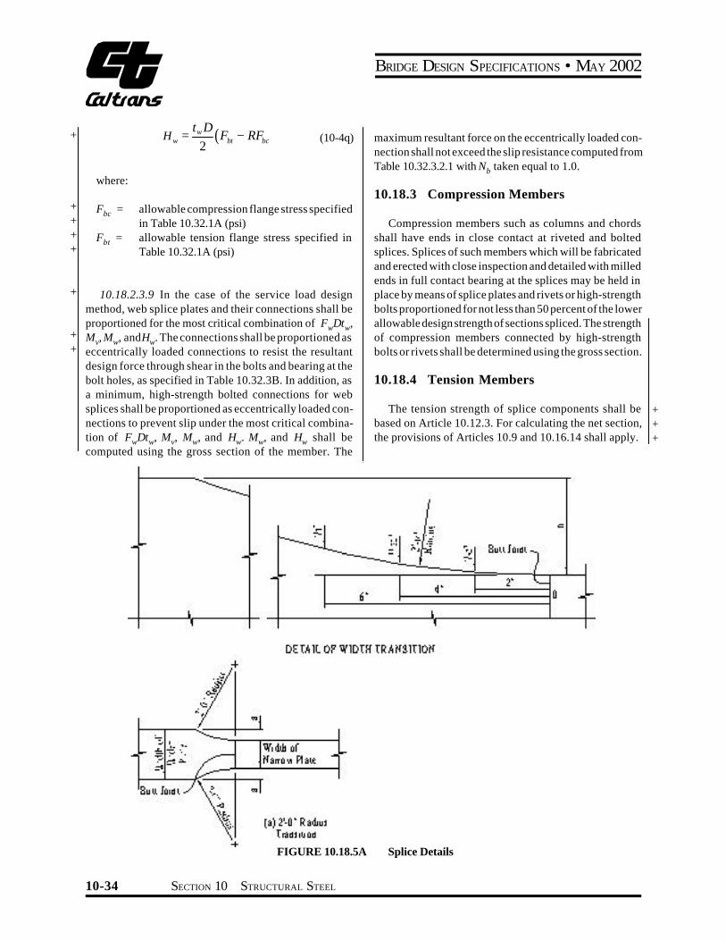
BRIDGE DESIGN SPECIFICATIONS bull MAY 2002
+
+ + + +
+ +
As a minimum in the case of the strength design method high-strength bolted connections for splices in tension members shall be proportioned to prevent slip at an overload design forcePo equal to the maximum tensile stress in the member due to Group I loading divided by 13 times the gross section of member The slip resistance shall be computed from Equation (10-172) In the case of the service load design method high-strength bolted connections shall be proportioned to prevent slip at a force equal to the allowable design strength specified in Article 101811 times the gross area of the member The slip resistance of the connection shall be determined as specified in Article 1032321
10185 Welding Splices
101851 Tension and compression members may be spliced by means of full penetration butt welds prefershyably without the use of splice plates
101852 Splices shall not be welded in field
101853 Material of different widths spliced by butt welds shall have transitions conforming to Figure 10185A At butt weld splices joining material of different thicknesses there shall be a uniform slope between the offset surfaces of not more than 1 in 2 12 with respect to the surface of either part
10191 General
101911 Except as otherwise provided herein conshynections for main members shall be designed in the cases of the service load design and the strength design methshyods for a capacity based on not less than 100 percent of the allowable design strength in the member
101912 Connections shall be made symmetrical about the axis of the members insofar as practicable Connecshytions except for lacing bars and handrails shall contain not less than two fasteners or equivalent weld
101913 Members including bracing preferably shall be so connected that their gravity axes will intersect in a point Eccentric connections shall be avoided if practishycable but if unavoidable the members shall be so proporshytioned that the combined forces will not exceed the allowshyable design strength
101914 In the case of connections which transfer total member shear at the end of the member the gross section shall be taken as the gross section of the conshynected elements
10192 End Connections of Floor Beams and Stringers
101921 The end connection shall be designed for calculated member loads The end connection angles of floor beams and stringers shall be not less than38 inch in finished thickness Except in cases of special end floor beam details each end connection for floor beams and stringers shall be made with two angles The length of these angles shall be as great as the flanges will permit Bracket or shelf angles which may be used to furnish support during erection shall not be considered in detershymining the number of fasteners required to transmit end shear
101922 End connection details shall be designed with special care to provide clearance for making the field connection
101923 End connections of stringers and floor beams preferably shall be bolted with high-strength bolts however they may be riveted or welded In the case of welded end connections they shall be designed for the vertical loads and the end bending moment resulting from the deflection of the members
101924 Where timber stringers frame into steel floor beams shelf angles with stiffeners shall be provided to carry the total reaction Shelf angles shall be not less than 716 inch thick
10193 End Connections of Diaphragms and Cross Frames
101931 The end connections for diaphragms or cross frames in straight rolled-beam and plate girder bridges shall be designed for the calculated member loads
101932 Vertical connection plates such as transshyverse stiffeners which connect diaphragms or cross frames to the beam or girder shall be rigidly connected to both top and bottom flanges
SECTION 10 STRUCTURAL STEEL 10-35
BRIDGE DESIGN SPECIFICATIONS bull MAY 2002
+ 10194 Block Shear Rupture Strength
+ 101941 General
+ Block shear rupture is one of several possible failure + modes for splices connections gusset plates and tension + members Block shear rupture failure is developed when + the net section of one segment ruptures and the gross + section of a perpendicular segment yields The web + connections of coped beams all tension connections + including connection plates splice plates and gusset + plates and tension members shall be investigated to + ensure that the adequate block shear rupture strength is + provided
+ 101942 Allowable Block Shear Rupture + Stress
+ In the Service Load Design Method calculated tension + stress based on the gross section shall not exceed the + allowable block shear rupture stress obtained from the + following equations
+ for vntn AA Dagger 06
+ ( ) gtnuvgybs AF AF AF 055033 += (10-4a)
+ for vntn AA lt 06
+ ( ) gtgyvnubs AF AF AF 055033 += (10-4b)
+ where
+ Ag = gross area of whole connected material (in2) + Avg = gross area along the plane resisting shear (in2) + Avn = net area along the plane resisting shear (in2) + Atg = gross area along the plane resisting tension (in2) + Atn = net area along the plane resisting tension (in2) + Fy = specified minimum yield strength of the conshy+ nected materials (psi) + Fu = specified minimum tensile strength of the conshy+ nected materials (psi) + Fbs = allowable block shear rupture stress (psi)
101943 Design Block Shear Rupture + Strength +
In the Strength Design Method calculated tension + force shall not exceed the design block shear rupture + strength obtained from the following equations +
+ for vntn AA Dagger 058 +
( tn )uvgybsbs F AF AT += 058f (10-4c)
for vntn AA lt 058
( tg )yvnubsbs F AF AT += 058f (10-4d)
where Tbs = design block shear rupture strength (lb) f bs = 08 reduction factor for block shear rupture
strength
1020 DIAPHRAGMS AND CROSS FRAMES
10201 General
Rolled beam and plate girder spans shall be provided with cross frames or diaphragms at each support and with + cross frames or diaphragms placed in all bays and spaced at intervals not to exceed 25 feet Diaphragms for rolled beams shall be at least13 and preferably12 the beam depth and for plate girders shall be at least 12 and preferably 34 the girder depth Cross frames shall be as deep as + practicable Cross frames shall preferably be of the cross type or vee type End cross frames or diaphragms shall be proportioned to adequately transmit all the lateral forces to the bearings Intermediate cross frames shall be normal + to the main beams and girders when the supports are skewed more than twenty degrees (20deg) Cross frames on horizontally curved steel girder bridges shall be designed as main members with adequate provisions for transfer of lateral forces from the girder flanges Cross frames and diaphragms shall be designed for horizontal wind loads as described in Article 10212 seismic loads and other applishy + cable loads +
10-36 SECTION 10 STRUCTURAL STEEL
BRIDGE DESIGN SPECIFICATIONS bull MAY 2002
+ 10202 Horizontal Force
+ The maximum horizontal force FD (lb) in the transshyverse diaphragms and cross frames is obtained from the following
+ FD = 114WSd (10-5)
+ where + W = wind load along the exterior flange (lbft) + Sd = diaphragm spacing (ft)
+ 102021 Deleted
+ 102022 Deleted
+ 10203 Deleted
+ 1021 LATERAL BRACING
10211 The need for lateral bracing shall be investigated + for wind loads seismic loads and other applicable lateral + loads Flanges attached to concrete decks or other decks
of comparable rigidity will not require lateral bracing
10212 A horizontal wind force of 50 pounds per square foot shall be applied to the area of the superstructure exposed in elevation Half this force shall be applied in the
+ plane of each flange The maximum induced stresses f + (psi) in the bottom flange of each girder in the system + when top flanges are continuously supported can be + computed from the following
+ cbR ff = (10-6)
+ [ ] ł
)
Ł
(-= -
bracing is provided when no bottomlateral
1102272 2 3SdLR
(10-7)
+ [ ] ł
)
Ł
(-= -
bracingis provided whenbottomlateral
0640059 1 2SdLR
(10-8)
+ 2
72
ff
cb cb t b
Mf = (10-9)
+ 2008 dcb W SM = (10-10)
L = span length (ft) tf = thickness of flange (in) + bf = width of flange (in) +
The stresses in flanges of each girder in the system + when top flanges are not continuously supported shall be + computed using the structural system in the plane of the + flanges under consideration The allowable stress shall be + factored in accordance with Article 322
10213 When required lateral bracing shall be placed in the exterior bays between diaphragms or cross frames All required lateral bracing shall be placed in or near the plane of the flange being braced
10214 Where beams or girders comprise the main members of through spans such members shall be stiffened against lateral deformation by means of gusset plates or knee braces with solid webs which shall be connected to the stiffeners on the main members and the floor beams If the unsupported length of the edge of the gusset plate (or solid web) exceeds 60 times its thickness the plate or web shall have a stiffening plate or angles connected along its unsupported edge
10215 Through truss spans deck truss spans and spandrel braced arches shall have top and bottom lateral bracing
10216 Bracing shall be composed of angles other shapes or welded sections The smallest angle used in bracing shall be 3 by 212 inches There shall be not less than 2 fasteners or equivalent weld in each end connection of the angles
10217 If a double system of bracing is used both systems may be considered effective simultaneously if the members meet the requirements both as tension and compression members The members shall be connected at their intersections
10218 The lateral bracing of compression chords preferably shall be as deep as the chords and effectively connected to both flanges
1022 CLOSED SECTIONS AND POCKETS
10221 Closed sections and pockets or depressions that will retain water shall be avoided where practicable
SECTION 10 STRUCTURAL STEEL 10-37
BRIDGE DESIGN SPECIFICATIONS bull MAY 2002
+ +
+ + + + +
Pockets shall be provided with effective drain holes or be filled with waterproofing material
10222 Details shall be so arranged that the destructive effects of bird life and the retention of dirt leaves and other foreign matter will be reduced to a minimum Where angles are used either singly or in pairs they preferably shall be placed with the vertical legs extending downward Structural tees preferably shall have the web extending downward
1023 WELDING
10231 General
102311 Steel base metal to be welded weld metal and welding design details shall conform to the requireshyments of the ANSIAASHTOAWS D15 Bridge Welding Code and the current Standard Specifications of the California Department of Transportation
102312 Welding symbols shall conform with the latest edition of the American Welding Society Publicashytion AWS A24
102313 Fabrication shall conform to the Stanshydard Specifications of the California Department of Transshyportation For fracture critical members see the AASHTO ldquoGuide Specifications for Fracture Critical Non-Redunshydant Steel Bridge Membersrdquo
10232 Effective Size of Fillet Welds
102321 Maximum Size of Fillet Welds
The maximum size of a fillet weld that may be assumed in the design of a connection shall be such that the stresses in the adjacent base material do not exceed the values allowed in Article 1032 The maximum size that may be used along edges of connected parts shall be
(1) Along edges of material less than14 inch thick the maximum size may be equal to the thickness of the material
(2) Along edges of material 14 inch or more in thickshyness the maximum size shall be 116 inch less than the thickness of the material unless the weld is especially designated on the drawings to be built out to obtain full throat thickness
102322 Minimum Size of Fillet Welds
The minimum fillet weld size shall be as shown in the following table
Base Metal Thickness of Minimum Size Thicker Part of Fillet Weld Jointed (T) in mm in mm
T pound 34 T pound 190 14 6 Single-pass WeldsT gt 34 Tgt 190 516 8 must be used
Except that the weld size need not exceed the thickness of the thinner part jointed For this exception particular care should be taken to provide sufficient preheat to ensure weld soundness
Smaller fillet welds may be approved by the Engineer based upon applied stress and the use of appropriate preheat
10233 Minimum Effective Length of Fillet Welds
The minimum effective length of a fillet weld shall be four times its size and in no case less than 112 inches
10234 Fillet Weld End Returns
Fillet welds which support a tensile force that is not parallel to the axis of the weld or which are proportioned to withstand repeated stress shall not terminate at corners of parts or members but shall be returned continuously full size around the corner for a length equal to twice the weld size where such return can be made in the same plane End returns shall be indicated on design and detail drawshyings
10235 Seal Welds
Seal welding shall preferably be accomplished by a continuous weld combining the functions of sealing and strength changing section only as the required strength or the requirements of minimum size fillet weld based on material thickness may necessitate
10-38 SECTION 10 STRUCTURAL STEEL
BRIDGE DESIGN SPECIFICATIONS bull MAY 2002
+
+ + + + + + +
+
+ + + + + + + + + + +
+ +
1024 FASTENERS
10241 General
102411 In proportioning fasteners for shear and tension the cross-sectional area based upon the nominal diameter shall be used Galvanization of AASHTO M253 (ASTM A490) and A354 Grade BD high strength bolts is not permitted due to hydrogen embrittlement problems These fasteners must be carefully evaluated before being utilized Requirements for bolts in these specifications shall be used for threaded rods threaded studs and anchor rods where applicable
102412 High-strength bolts may be substituted for Grade 1 rivets (ASTM A 502) or ASTM A307 bolts When AASHTO M 164 (ASTM A325) high-strength bolts are substituted for ASTM A307 bolts they shall be tightened to the full effort of a man using an ordinary spud wrench
102413 All bolts except high-strength bolts tensioned to the requirements of the Standard Specificashytions of the California Department of Transportation shall have single self-locking nut double nuts or a nut with a thread locking system (anaerobic adhesive) to prevent nut loosening The thread locking system is the preferred method for bolt diameters of one inch or less The thread locking system shall not be used on bolt diameters greater than one inch When using the double nut method a torque value for the jam nut relative to the main nut shall be shown on the plans to assure that a reasonable effort will be made to lock the two nuts together
102414 Joints required to resist shear between their connected parts are designated as either slip-critical or bearing-type connections Slip-critical joints are reshyquired for joints subject to stress reversal heavy impact loads severe vibration or where stress and strain due to joint slippage would be detrimental to the serviceability of the structure They include
(1) Joints subject to fatigue loading (2) Joints with bolts installed in oversized holes (3) Except where the Engineer intends otherwise and
so indicates in the contract documents joints with bolts installed in slotted holes where the force on the joint is in a direction other than normal (beshytween approximately 80 and 100 degrees) to the axis of the slot
(4) Joints subject to significant load reversal (5) Joints in which welds and bolts share in transmitshy
ting load at a common faying surface (6) Joints in which in the judgment of the Engineer
any slip would be critical to the performance of the joint or the structure and so designated on the contract plans and specifications
102415 High-strength bolted connections subshyject to tension or combined shear and tension shall be designed as slip-critical connections
102416 Bolted bearing-type connections using high-strength bolts shall be limited to members in comshypression and secondary members
102417 The effective bearing area of a fastener shall be its diameter multiplied by the thickness of the metal on which it bears In metal less than 38 inch thick counshytersunk fasteners shall not be assumed to carry stress In metal 38 inch thick and over one-half the depth of counshytersink shall be omitted in calculating the bearing area
102418 In determining whether the bolt threads are excluded from the shear planes of the contact surfaces thread length of bolts shall be calculated as two thread pitches greater than the specified thread length as an allowance for thread run out
102419 In bearing-type connections pull-out shear in a plate should be investigated between the end of the plate and the end row of fasteners (See Table 10323B footnote h or Article 105613)
+ +
SECTION 10 STRUCTURAL STEEL 10-39
5
BRIDGE DESIGN SPECIFICATIONS bull MAY 2002
+
TABLE 10242 Nominal Hole Dimension
Hole Dimension (in)Bolt
Standard Oversize Short Slot Long SlotDiameter (in) (Diameter) (Diameter) (Width x Length) (Width x Length)
1116 1316
58 1116 x 78
1116 x 1916
34 1316
1516 1316 x 1 1316 x 178
78 1516 1116
15 16 x 118 1516 x 2316
11 41 1116 1116 x 1516 1116 x 212
(d + 116) x (d + 38) (d + 116) x (25 x d)Dagger 118 d + 116 d + 516
10242 Hole Types 100 degrees) to the axis of the slot Long slotted holes may
Hole types for high-strength bolted connections are be used in one of the connected parts at any individual standard holes oversize holes short slotted holes and faying surface without regard for the direction of applied long slotted holes The nominal dimensions for each type load on connections which satisfy the requirements of hole shall be not greater than those shown in Table 10242 Article 1032321 or Article 105731 as applicable
10243 Washer Requirements102421 In the absence of approval by the Engishyneer for use of other hole types standard holes shall be used in high-strength bolted connections Design details shall provide for washers in highshy
strength bolted connections as follows 102422 When approved by the Engineer overshy
size short slotted hole or long slotted holes may be used 102431 Where the outer face of the bolted parts subject to the following joint detail requirements has slope greater than 120 with respect to a plane normal
to the bolt axis a hardened beveled washer shall be used to compensate for the lack of parallelism Beveled washers
of connections which satisfy the requirements of Article 1024221 Oversize holes may be used in all plies
other than the standard 16 slope shall be detailed in the plans
shall not be used in bearing-type connections 1032321 or Article 10573 as applicable Oversize holes
102432 Hardened washers are not required for connections using AASHTO M164 (ASTM A325) and
or all plies of high-strength bolted connections designed 1024222 Short slotted holes may be used in any
AASHTO M253 (ASTM A490) bolts except as required in on the basis of Table 10323B or Table 1056A as appli- Articles 102433 through 102437 cable provided the load is applied approximately normal (between 80 and 100 degrees) to the axis of the slot Short 102433 Hardened washers shall be used under slotted holes may be used without regard for the direction the element turned in tightening and to cover oversize or of applied load in any or all plies of connections which short slotted holes in the outer ply satisfy the requirements of Article 1032321 or Article 105731 as applicable 102434 Irrespective of the tightening method
hardened washers shall be used under both the head and the nut when AASHTO M253 (ASTM A490) bolts are to
of the connected parts at any individual faying surface in 1024223 Long slotted holes may be used in one
be installed in material having a specified yield strength high-strength bolted connections designed on the basis less than 40000 psi of Table 10323B or Table 1056A as applicable provided the load is applied approximately normal (between 80 and
+ +
+ + +
+ +
+ + +
10-40 SECTION 10 STRUCTURAL STEEL
BRIDGE DESIGN SPECIFICATIONS bull MAY 2002
+ +
+ + + + +
Pockets shall be provided with effective drain holes or be filled with waterproofing material
10222 Details shall be so arranged that the destructive effects of bird life and the retention of dirt leaves and other foreign matter will be reduced to a minimum Where angles are used either singly or in pairs they preferably shall be placed with the vertical legs extending downward Structural tees preferably shall have the web extending downward
1023 WELDING
10231 General
102311 Steel base metal to be welded weld metal and welding design details shall conform to the requireshyments of the ANSIAASHTOAWS D15 Bridge Welding Code and the current Standard Specifications of the California Department of Transportation
102312 Welding symbols shall conform with the latest edition of the American Welding Society Publicashytion AWS A24
102313 Fabrication shall conform to the Stanshydard Specifications of the California Department of Transshyportation For fracture critical members see the AASHTO ldquoGuide Specifications for Fracture Critical Non-Redunshydant Steel Bridge Membersrdquo
10232 Effective Size of Fillet Welds
102321 Maximum Size of Fillet Welds
The maximum size of a fillet weld that may be assumed in the design of a connection shall be such that the stresses in the adjacent base material do not exceed the values allowed in Article 1032 The maximum size that may be used along edges of connected parts shall be
(1) Along edges of material less than14 inch thick the maximum size may be equal to the thickness of the material
(2) Along edges of material 14 inch or more in thickshyness the maximum size shall be 116 inch less than the thickness of the material unless the weld is especially designated on the drawings to be built out to obtain full throat thickness
102322 Minimum Size of Fillet Welds
The minimum fillet weld size shall be as shown in the following table
Base Metal Thickness of Minimum Size Thicker Part of Fillet Weld Jointed (T) in mm in mm
T pound 34 T pound 190 14 6 Single-pass WeldsT gt 34 Tgt 190 516 8 must be used
Except that the weld size need not exceed the thickness of the thinner part jointed For this exception particular care should be taken to provide sufficient preheat to ensure weld soundness
Smaller fillet welds may be approved by the Engineer based upon applied stress and the use of appropriate preheat
10233 Minimum Effective Length of Fillet Welds
The minimum effective length of a fillet weld shall be four times its size and in no case less than 112 inches
10234 Fillet Weld End Returns
Fillet welds which support a tensile force that is not parallel to the axis of the weld or which are proportioned to withstand repeated stress shall not terminate at corners of parts or members but shall be returned continuously full size around the corner for a length equal to twice the weld size where such return can be made in the same plane End returns shall be indicated on design and detail drawshyings
10235 Seal Welds
Seal welding shall preferably be accomplished by a continuous weld combining the functions of sealing and strength changing section only as the required strength or the requirements of minimum size fillet weld based on material thickness may necessitate
10-38 SECTION 10 STRUCTURAL STEEL
BRIDGE DESIGN SPECIFICATIONS bull MAY 2002
+
+ + + + + + +
+
+ + + + + + + + + + +
+ +
1024 FASTENERS
10241 General
102411 In proportioning fasteners for shear and tension the cross-sectional area based upon the nominal diameter shall be used Galvanization of AASHTO M253 (ASTM A490) and A354 Grade BD high strength bolts is not permitted due to hydrogen embrittlement problems These fasteners must be carefully evaluated before being utilized Requirements for bolts in these specifications shall be used for threaded rods threaded studs and anchor rods where applicable
102412 High-strength bolts may be substituted for Grade 1 rivets (ASTM A 502) or ASTM A307 bolts When AASHTO M 164 (ASTM A325) high-strength bolts are substituted for ASTM A307 bolts they shall be tightened to the full effort of a man using an ordinary spud wrench
102413 All bolts except high-strength bolts tensioned to the requirements of the Standard Specificashytions of the California Department of Transportation shall have single self-locking nut double nuts or a nut with a thread locking system (anaerobic adhesive) to prevent nut loosening The thread locking system is the preferred method for bolt diameters of one inch or less The thread locking system shall not be used on bolt diameters greater than one inch When using the double nut method a torque value for the jam nut relative to the main nut shall be shown on the plans to assure that a reasonable effort will be made to lock the two nuts together
102414 Joints required to resist shear between their connected parts are designated as either slip-critical or bearing-type connections Slip-critical joints are reshyquired for joints subject to stress reversal heavy impact loads severe vibration or where stress and strain due to joint slippage would be detrimental to the serviceability of the structure They include
(1) Joints subject to fatigue loading (2) Joints with bolts installed in oversized holes (3) Except where the Engineer intends otherwise and
so indicates in the contract documents joints with bolts installed in slotted holes where the force on the joint is in a direction other than normal (beshytween approximately 80 and 100 degrees) to the axis of the slot
(4) Joints subject to significant load reversal (5) Joints in which welds and bolts share in transmitshy
ting load at a common faying surface (6) Joints in which in the judgment of the Engineer
any slip would be critical to the performance of the joint or the structure and so designated on the contract plans and specifications
102415 High-strength bolted connections subshyject to tension or combined shear and tension shall be designed as slip-critical connections
102416 Bolted bearing-type connections using high-strength bolts shall be limited to members in comshypression and secondary members
102417 The effective bearing area of a fastener shall be its diameter multiplied by the thickness of the metal on which it bears In metal less than 38 inch thick counshytersunk fasteners shall not be assumed to carry stress In metal 38 inch thick and over one-half the depth of counshytersink shall be omitted in calculating the bearing area
102418 In determining whether the bolt threads are excluded from the shear planes of the contact surfaces thread length of bolts shall be calculated as two thread pitches greater than the specified thread length as an allowance for thread run out
102419 In bearing-type connections pull-out shear in a plate should be investigated between the end of the plate and the end row of fasteners (See Table 10323B footnote h or Article 105613)
+ +
SECTION 10 STRUCTURAL STEEL 10-39
5
BRIDGE DESIGN SPECIFICATIONS bull MAY 2002
+
TABLE 10242 Nominal Hole Dimension
Hole Dimension (in)Bolt
Standard Oversize Short Slot Long SlotDiameter (in) (Diameter) (Diameter) (Width x Length) (Width x Length)
1116 1316
58 1116 x 78
1116 x 1916
34 1316
1516 1316 x 1 1316 x 178
78 1516 1116
15 16 x 118 1516 x 2316
11 41 1116 1116 x 1516 1116 x 212
(d + 116) x (d + 38) (d + 116) x (25 x d)Dagger 118 d + 116 d + 516
10242 Hole Types 100 degrees) to the axis of the slot Long slotted holes may
Hole types for high-strength bolted connections are be used in one of the connected parts at any individual standard holes oversize holes short slotted holes and faying surface without regard for the direction of applied long slotted holes The nominal dimensions for each type load on connections which satisfy the requirements of hole shall be not greater than those shown in Table 10242 Article 1032321 or Article 105731 as applicable
10243 Washer Requirements102421 In the absence of approval by the Engishyneer for use of other hole types standard holes shall be used in high-strength bolted connections Design details shall provide for washers in highshy
strength bolted connections as follows 102422 When approved by the Engineer overshy
size short slotted hole or long slotted holes may be used 102431 Where the outer face of the bolted parts subject to the following joint detail requirements has slope greater than 120 with respect to a plane normal
to the bolt axis a hardened beveled washer shall be used to compensate for the lack of parallelism Beveled washers
of connections which satisfy the requirements of Article 1024221 Oversize holes may be used in all plies
other than the standard 16 slope shall be detailed in the plans
shall not be used in bearing-type connections 1032321 or Article 10573 as applicable Oversize holes
102432 Hardened washers are not required for connections using AASHTO M164 (ASTM A325) and
or all plies of high-strength bolted connections designed 1024222 Short slotted holes may be used in any
AASHTO M253 (ASTM A490) bolts except as required in on the basis of Table 10323B or Table 1056A as appli- Articles 102433 through 102437 cable provided the load is applied approximately normal (between 80 and 100 degrees) to the axis of the slot Short 102433 Hardened washers shall be used under slotted holes may be used without regard for the direction the element turned in tightening and to cover oversize or of applied load in any or all plies of connections which short slotted holes in the outer ply satisfy the requirements of Article 1032321 or Article 105731 as applicable 102434 Irrespective of the tightening method
hardened washers shall be used under both the head and the nut when AASHTO M253 (ASTM A490) bolts are to
of the connected parts at any individual faying surface in 1024223 Long slotted holes may be used in one
be installed in material having a specified yield strength high-strength bolted connections designed on the basis less than 40000 psi of Table 10323B or Table 1056A as applicable provided the load is applied approximately normal (between 80 and
+ +
+ + +
+ +
+ + +
10-40 SECTION 10 STRUCTURAL STEEL

BRIDGE DESIGN SPECIFICATIONS bull MAY 2002
+
+ + + + + + +
+
+ + + + + + + + + + +
+ +
1024 FASTENERS
10241 General
102411 In proportioning fasteners for shear and tension the cross-sectional area based upon the nominal diameter shall be used Galvanization of AASHTO M253 (ASTM A490) and A354 Grade BD high strength bolts is not permitted due to hydrogen embrittlement problems These fasteners must be carefully evaluated before being utilized Requirements for bolts in these specifications shall be used for threaded rods threaded studs and anchor rods where applicable
102412 High-strength bolts may be substituted for Grade 1 rivets (ASTM A 502) or ASTM A307 bolts When AASHTO M 164 (ASTM A325) high-strength bolts are substituted for ASTM A307 bolts they shall be tightened to the full effort of a man using an ordinary spud wrench
102413 All bolts except high-strength bolts tensioned to the requirements of the Standard Specificashytions of the California Department of Transportation shall have single self-locking nut double nuts or a nut with a thread locking system (anaerobic adhesive) to prevent nut loosening The thread locking system is the preferred method for bolt diameters of one inch or less The thread locking system shall not be used on bolt diameters greater than one inch When using the double nut method a torque value for the jam nut relative to the main nut shall be shown on the plans to assure that a reasonable effort will be made to lock the two nuts together
102414 Joints required to resist shear between their connected parts are designated as either slip-critical or bearing-type connections Slip-critical joints are reshyquired for joints subject to stress reversal heavy impact loads severe vibration or where stress and strain due to joint slippage would be detrimental to the serviceability of the structure They include
(1) Joints subject to fatigue loading (2) Joints with bolts installed in oversized holes (3) Except where the Engineer intends otherwise and
so indicates in the contract documents joints with bolts installed in slotted holes where the force on the joint is in a direction other than normal (beshytween approximately 80 and 100 degrees) to the axis of the slot
(4) Joints subject to significant load reversal (5) Joints in which welds and bolts share in transmitshy
ting load at a common faying surface (6) Joints in which in the judgment of the Engineer
any slip would be critical to the performance of the joint or the structure and so designated on the contract plans and specifications
102415 High-strength bolted connections subshyject to tension or combined shear and tension shall be designed as slip-critical connections
102416 Bolted bearing-type connections using high-strength bolts shall be limited to members in comshypression and secondary members
102417 The effective bearing area of a fastener shall be its diameter multiplied by the thickness of the metal on which it bears In metal less than 38 inch thick counshytersunk fasteners shall not be assumed to carry stress In metal 38 inch thick and over one-half the depth of counshytersink shall be omitted in calculating the bearing area
102418 In determining whether the bolt threads are excluded from the shear planes of the contact surfaces thread length of bolts shall be calculated as two thread pitches greater than the specified thread length as an allowance for thread run out
102419 In bearing-type connections pull-out shear in a plate should be investigated between the end of the plate and the end row of fasteners (See Table 10323B footnote h or Article 105613)
+ +
SECTION 10 STRUCTURAL STEEL 10-39
5
BRIDGE DESIGN SPECIFICATIONS bull MAY 2002
+
TABLE 10242 Nominal Hole Dimension
Hole Dimension (in)Bolt
Standard Oversize Short Slot Long SlotDiameter (in) (Diameter) (Diameter) (Width x Length) (Width x Length)
1116 1316
58 1116 x 78
1116 x 1916
34 1316
1516 1316 x 1 1316 x 178
78 1516 1116
15 16 x 118 1516 x 2316
11 41 1116 1116 x 1516 1116 x 212
(d + 116) x (d + 38) (d + 116) x (25 x d)Dagger 118 d + 116 d + 516
10242 Hole Types 100 degrees) to the axis of the slot Long slotted holes may
Hole types for high-strength bolted connections are be used in one of the connected parts at any individual standard holes oversize holes short slotted holes and faying surface without regard for the direction of applied long slotted holes The nominal dimensions for each type load on connections which satisfy the requirements of hole shall be not greater than those shown in Table 10242 Article 1032321 or Article 105731 as applicable
10243 Washer Requirements102421 In the absence of approval by the Engishyneer for use of other hole types standard holes shall be used in high-strength bolted connections Design details shall provide for washers in highshy
strength bolted connections as follows 102422 When approved by the Engineer overshy
size short slotted hole or long slotted holes may be used 102431 Where the outer face of the bolted parts subject to the following joint detail requirements has slope greater than 120 with respect to a plane normal
to the bolt axis a hardened beveled washer shall be used to compensate for the lack of parallelism Beveled washers
of connections which satisfy the requirements of Article 1024221 Oversize holes may be used in all plies
other than the standard 16 slope shall be detailed in the plans
shall not be used in bearing-type connections 1032321 or Article 10573 as applicable Oversize holes
102432 Hardened washers are not required for connections using AASHTO M164 (ASTM A325) and
or all plies of high-strength bolted connections designed 1024222 Short slotted holes may be used in any
AASHTO M253 (ASTM A490) bolts except as required in on the basis of Table 10323B or Table 1056A as appli- Articles 102433 through 102437 cable provided the load is applied approximately normal (between 80 and 100 degrees) to the axis of the slot Short 102433 Hardened washers shall be used under slotted holes may be used without regard for the direction the element turned in tightening and to cover oversize or of applied load in any or all plies of connections which short slotted holes in the outer ply satisfy the requirements of Article 1032321 or Article 105731 as applicable 102434 Irrespective of the tightening method
hardened washers shall be used under both the head and the nut when AASHTO M253 (ASTM A490) bolts are to
of the connected parts at any individual faying surface in 1024223 Long slotted holes may be used in one
be installed in material having a specified yield strength high-strength bolted connections designed on the basis less than 40000 psi of Table 10323B or Table 1056A as applicable provided the load is applied approximately normal (between 80 and
+ +
+ + +
+ +
+ + +
10-40 SECTION 10 STRUCTURAL STEEL
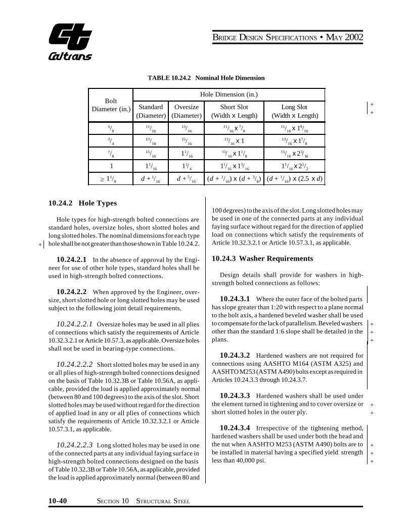


![ÏÑÇÓÉ ÊÒÇíÏ ÇáÓåæã Ýí ÇáÌíÒÇä ÇáÎÑÓÇäíÉ ÇáãÓáÍÉ … file130 :. (deflections): - - -1.... -2. ( ). (Long-Term deflection) ACI 435R-95.( ) [2]](https://img.pdfslide.us/doc/110x75/5aab8f9d7f8b9ac55c8c08d1/-deflections-1-2-long-term-deflection-aci-435r-95-.jpg)