Embed Size (px)
Citation preview
Bridge Design Report
Jeremy HenningsMatt Kilmer
Tim WilliamsNina Mairena
Introduction
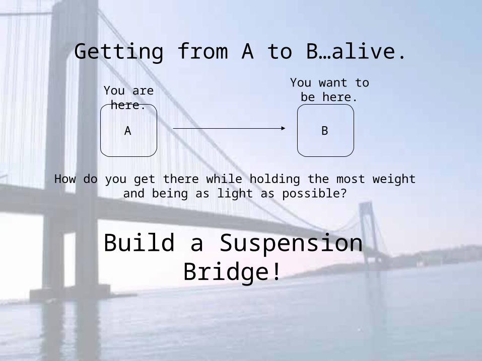
Getting from A to B…alive.
A B
How do you get there while holding the most weight and being as light as possible?
Build a Suspension Bridge!
You are here.You want to be
here.
• When you need to get to point A to point B a suspension bridge is the way to go.
• If you want a bridge that is light, go with a suspension bridge.
• If you want a bridge that has style, go with a suspension bridge.
• If you want to make it alive, go with a suspension bridge.
But Why a Suspension Bridge?
Outline
• Tension Component Test
• Prototype Design
• Redesign
• Final Design
• Bridge Testing
• Conclusion
Tension Component Test
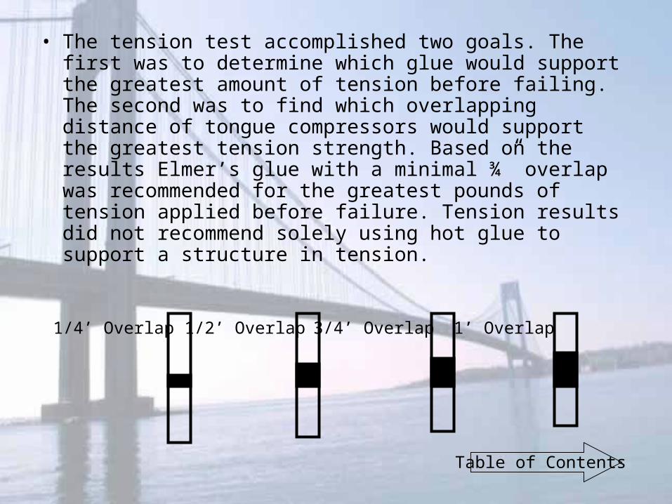
• The tension test accomplished two goals. The first was to determine which glue would support the greatest amount of tension before failing. The second was to find which overlapping distance of tongue compressors would support the greatest tension strength. Based on the results Elmer’s glue with a minimal ¾” overlap was recommended for the greatest pounds of tension applied before failure. Tension results did not recommend solely using hot glue to support a structure in tension.
1/4’ Overlap 1/2’ Overlap 3/4’ Overlap 1’ Overlap
Table of Contents
Prototype Design
Prototype Analysis
• Goal:• Support an efficient load
• Design:• Simple design with ease of construction.
• Mainframe structure with towers supporting wire to support the frame.
• As frame sags from the weight of the load the wire would be there to support the frame.
• Keeping the weight down when building the frame allows for the potential of a great efficiency score because of wire strength to weight ratio.
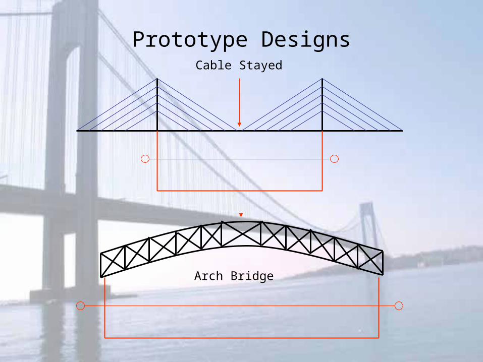
Prototype DesignsCable Stayed
Arch Bridge
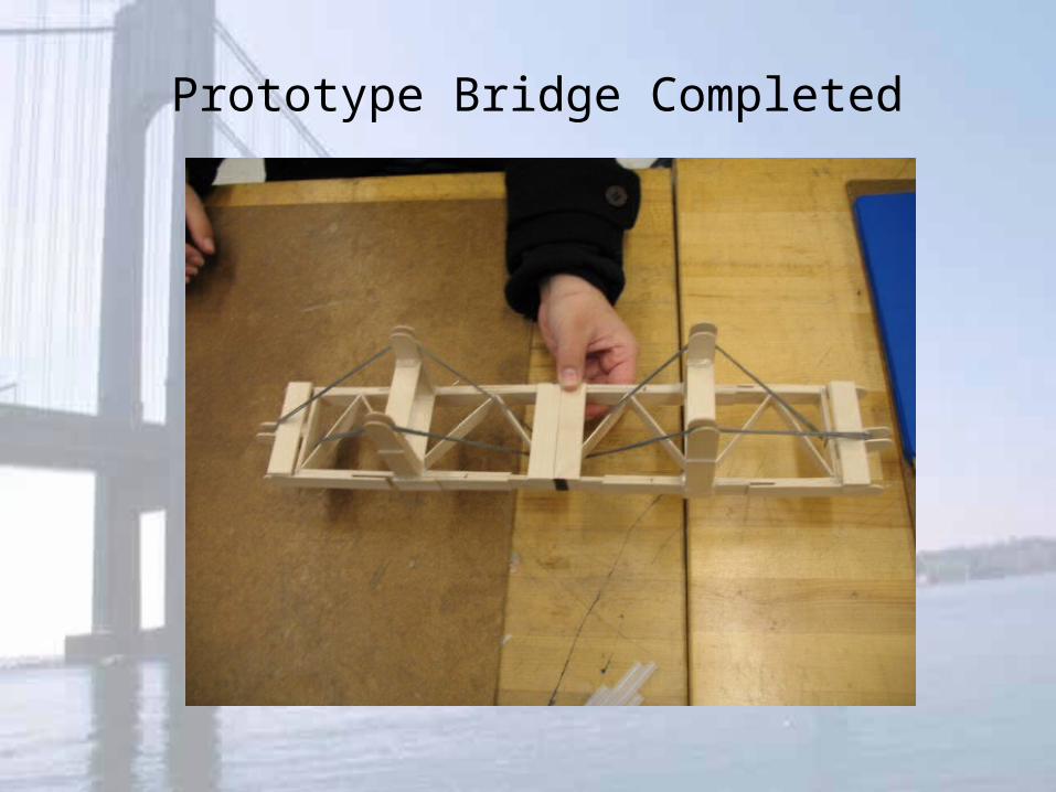
Prototype Bridge Completed
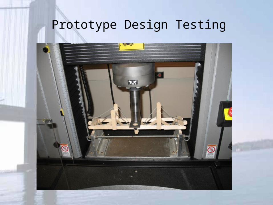
Prototype Design Testing
Prototype Performance
• Design flaw
• Wire wouldn’t support the central frame when the frame began to give way.
• Wire was not attached to the Jig so as the center of the bridge gave way the ends of the bridge bowed upwards, leaving the wire tensionless.
• The frame and nothing else solely supported the entire load.
• Results• Weight of bridge: .375 lbs• Weight supported: 120 lbs• Efficiency: 320
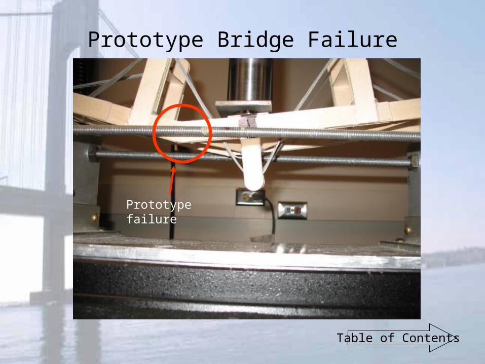
Prototype Bridge Failure
Prototype failure
Table of Contents
Redesign
Things to Improve…
• Square up the base so it would be level• Place towers wider out and above the beams on
the jig• Increase the angle of the fishing line to obtain
more tension in the line• Attach fishing line directly to the jig to help
improve tension• Make the base stronger by adding more tongue
depressors
Redesign #1
• Build 2 frames, free of one another
• Attach line to inner frame to hold but have towers placed on the outer frame– Reduce stress on the frame
• Frame built wider and place 8 towers – Inner towers would be higher to increase incline and
out towers were shorter and above the jig frame to help reduce stress
• Hoping to achieve tension in fishing line
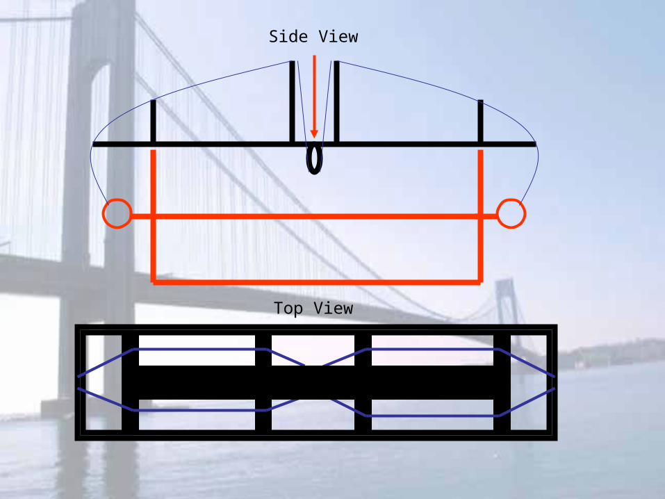
Top View
Side View
Redesign #2
• Monday before testing, “It’s good, but…oh nevermind.” Joe Giordano
• Create a truss like bridge with a hanging basket from the center
• Fishing line would be in tension and hopefully would be where the bridge failed
• Added support of a truss frame with the tension of the fishing line
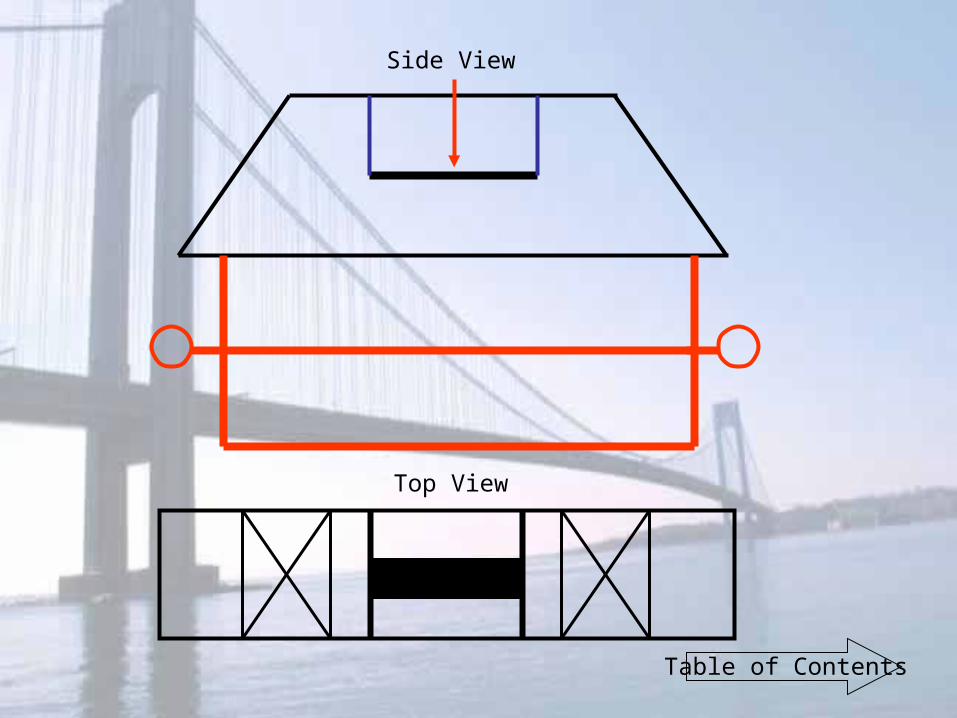
Top View
Side View
Table of Contents
Final Design
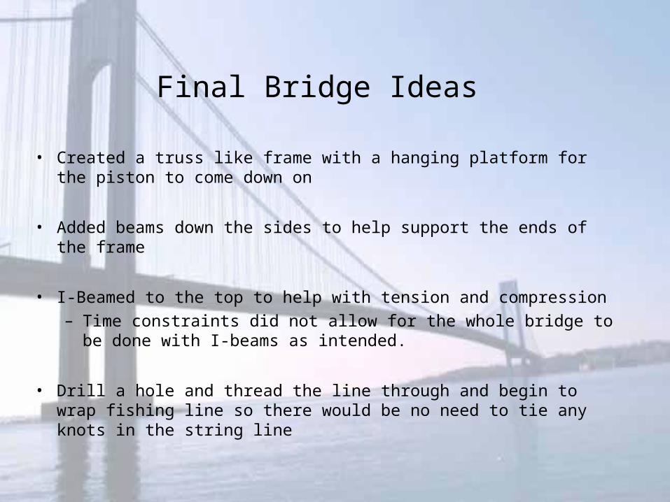
• Created a truss like frame with a hanging platform for the piston to come down on
• Added beams down the sides to help support the ends of the frame
• I-Beamed to the top to help with tension and compression – Time constraints did not allow for the whole bridge to be done
with I-beams as intended.
• Drill a hole and thread the line through and begin to wrap fishing line so there would be no need to tie any knots in the string line
Final Bridge Ideas
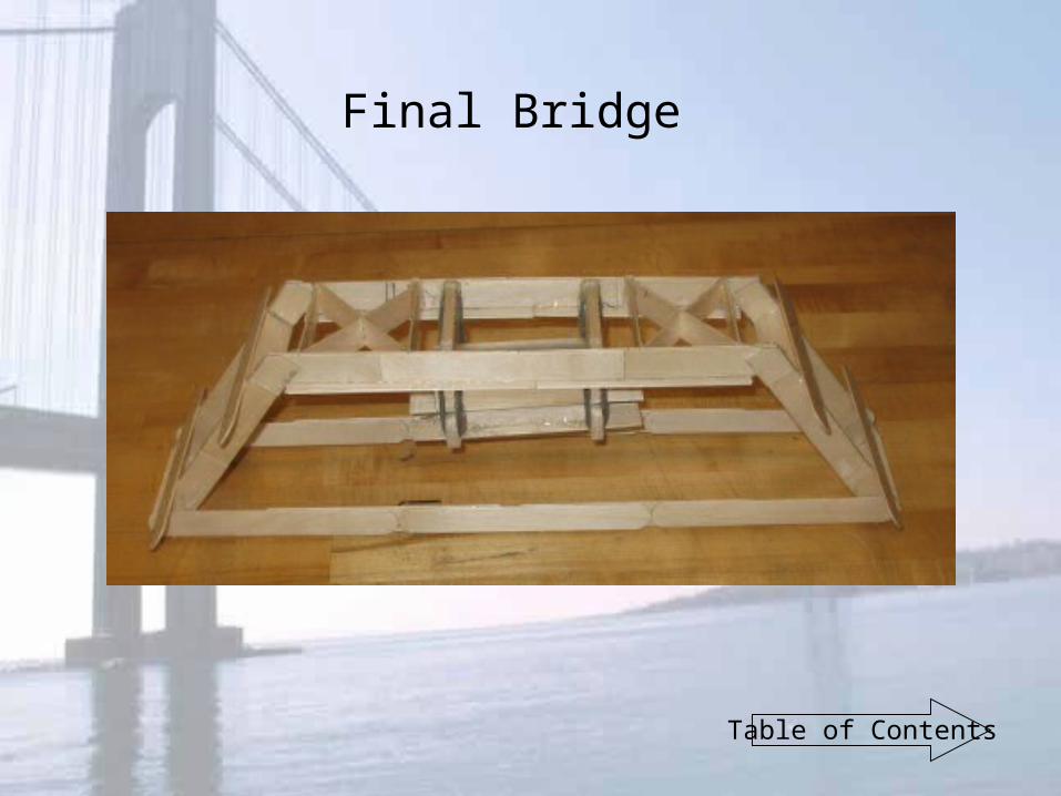
Final Bridge
Table of Contents
Bridge Testing
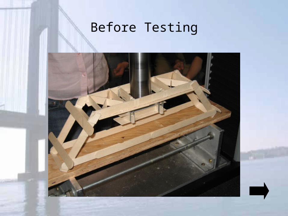
Before Testing
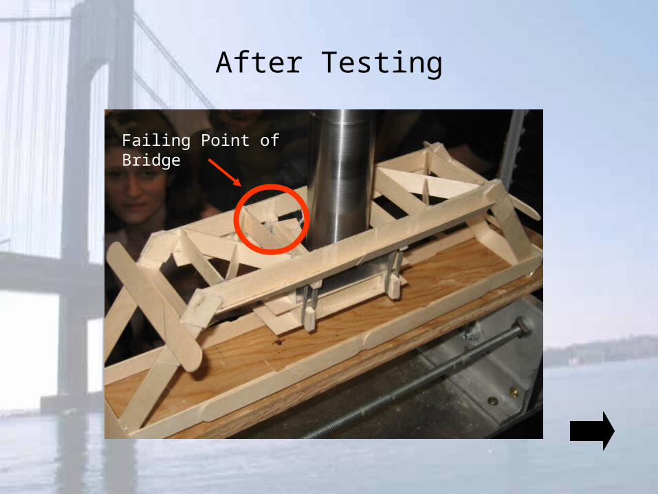
After Testing
Failing Point of Bridge
Performance?
• The bridge held more than our first trial but did not meet up to what was expected
• Hoping for the fish line to fail before the frame of the bridge
• Even though this was a final design, it was still a prototype in a way
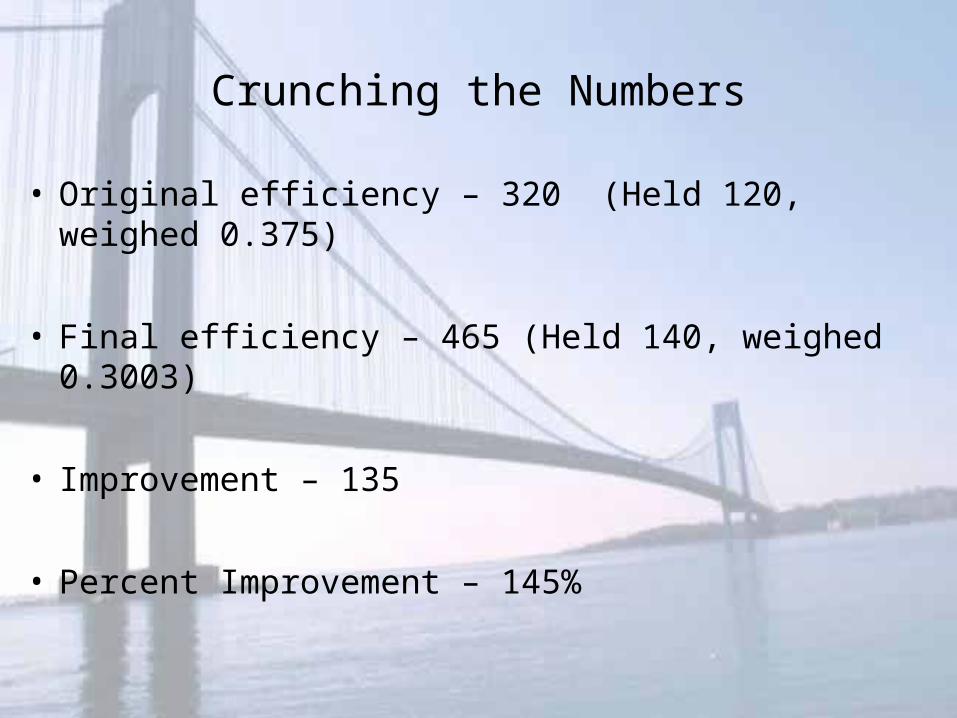
Crunching the Numbers
• Original efficiency – 320 (Held 120, weighed 0.375)
• Final efficiency – 465 (Held 140, weighed 0.3003)
• Improvement – 135
• Percent Improvement – 145%
Further Improvements
• I-Beam the entire frame for increased strength and durability
• Properly secure bridge on jig !
• Place the basket wires on top of the frame instead of inside !
• Wind all the lines at the same time and wrap them around in a equal amount
– Requires at least 5 people to tie down properly
Table of Contents
Conclusion
• The goal to build a bridge of maximum load bearing and minimum weight was reached.
• To accomplish this goal, a suspension design was chosen, using the 65 pound line, and Elmer’s glue based on the tests preformed on the materials.
• The first bridge, which had a good efficiency of 320, did not utilize the suspension aspect of the bridge.
• Since the bridge failed at the frame, it was decided that I-beams would be used.
• The design was changed to a two frame bridge with the inner frame completely supported by wire attached to the outer frame.
• This design worked better than the first, achieving an efficiency of 465. A decent improvement which could be increased if better end more glue was used.
Table of ContentsBeginning of Show
Final Comments