Embed Size (px)
DESCRIPTION
Bridge Design
Citation preview

LRFD Design ofLRFD Design ofShallow FoundationsShallow Foundations
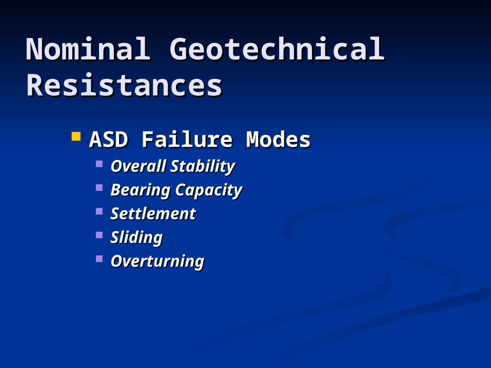
Nominal Geotechnical Nominal Geotechnical ResistancesResistances
ASD Failure ModesASD Failure Modes Overall StabilityOverall Stability Bearing CapacityBearing Capacity SettlementSettlement SlidingSliding OverturningOverturning
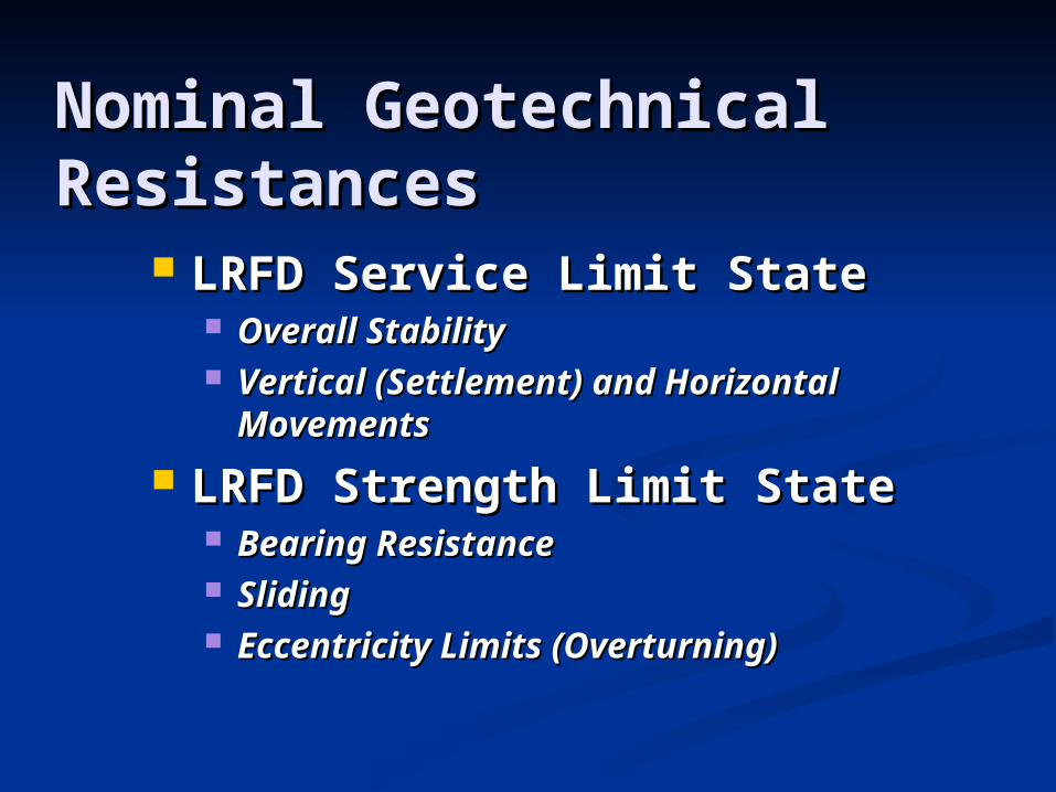
Nominal Geotechnical Nominal Geotechnical ResistancesResistances
LRFD Service Limit StateLRFD Service Limit State Overall StabilityOverall Stability Vertical (Settlement) and Horizontal Vertical (Settlement) and Horizontal
MovementsMovements
LRFD Strength Limit StateLRFD Strength Limit State Bearing ResistanceBearing Resistance SlidingSliding Eccentricity Limits (Overturning)Eccentricity Limits (Overturning)
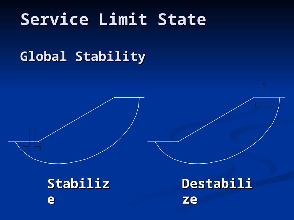
StabilizeStabilize DestabilizDestabilizee
Service Limit StateService Limit State
Global StabilityGlobal Stability

Global Stability Factor of Safety Global Stability Factor of Safety – Method of Slices– Method of Slices
+
WT
WT
WTWT
NN
TT
TT
l lcl
cl
N tan N tan
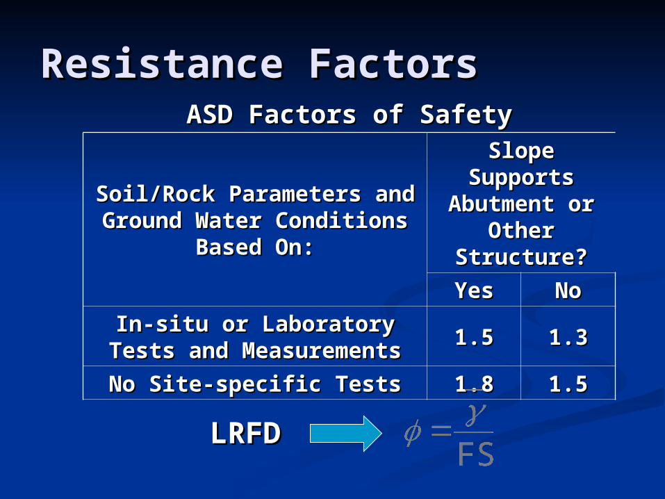
ASD Factors of SafetyASD Factors of Safety
Soil/Rock Parameters and Soil/Rock Parameters and Ground Water Conditions Ground Water Conditions
Based On:Based On:
Slope Supports Slope Supports Abutment or Abutment or
Other Other Structure?Structure?
YesYes NoNo
In-situ or Laboratory Tests and In-situ or Laboratory Tests and MeasurementsMeasurements 1.51.5 1.31.3
No Site-specific TestsNo Site-specific Tests 1.81.8 1.51.5
Resistance FactorsResistance Factors
LRFDLRFD
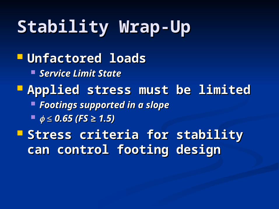
Stability Wrap-UpStability Wrap-Up
Unfactored loadsUnfactored loads Service Limit StateService Limit State
Applied stress must be limitedApplied stress must be limited Footings supported in a slopeFootings supported in a slope ≤≤ 0.65 (FS ≥ 1.5)0.65 (FS ≥ 1.5)
Stress criteria for stability can control Stress criteria for stability can control footing designfooting design

Service Limit State Design – Service Limit State Design – SettlementSettlement Cohesive SoilsCohesive Soils
Evaluate Using Consolidation TheoryEvaluate Using Consolidation Theory
Cohesionless SoilsCohesionless Soils Evaluate Using Empirical or Other Conventional Evaluate Using Empirical or Other Conventional
MethodsMethods Hough MethodHough Method
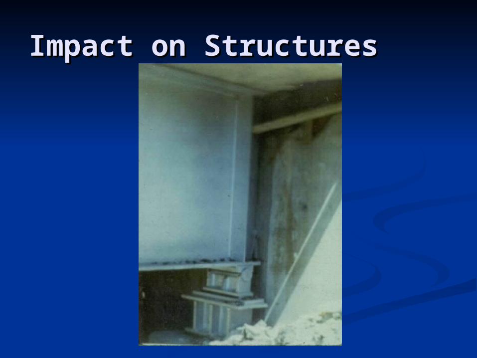
Impact on StructuresImpact on Structures
Settlement of Granular vs. Settlement of Granular vs. Cohesive SoilsCohesive Soils Relative importance of settlement Relative importance of settlement
components for different soil typescomponents for different soil types ElasticElastic Primary ConsolidationPrimary Consolidation Secondary Settlement (Creep)Secondary Settlement (Creep)
Settlement of Granular vs. Settlement of Granular vs. Cohesive SoilsCohesive Soils Structural effects of settlement Structural effects of settlement
componentscomponents Include Transient Loads if Drained Include Transient Loads if Drained
Loading is Expected and for Computing Loading is Expected and for Computing Initial Elastic SettlementInitial Elastic Settlement
Transient Loads May Be Omitted When Transient Loads May Be Omitted When Computing Consolidation Settlement of Computing Consolidation Settlement of Cohesive SoilsCohesive Soils
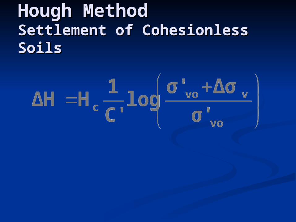
Hough MethodHough MethodSettlement of Cohesionless SoilsSettlement of Cohesionless Soils

Stress Stress Below Below FootingFooting
Boussinesq Boussinesq Pressure Pressure IsobarsIsobars
1B 2B2B 1B
1B
2B
3B
4B
5B
1B
2B
3B
4B
5B
0.2q
0.1q
0.08q
0.06q
0.04q
0.4q
0.3q
0.2q
0.1q
0.6q
0.8q
0.4q
0.6q
qo
B/2B/2STRIP SQUARE
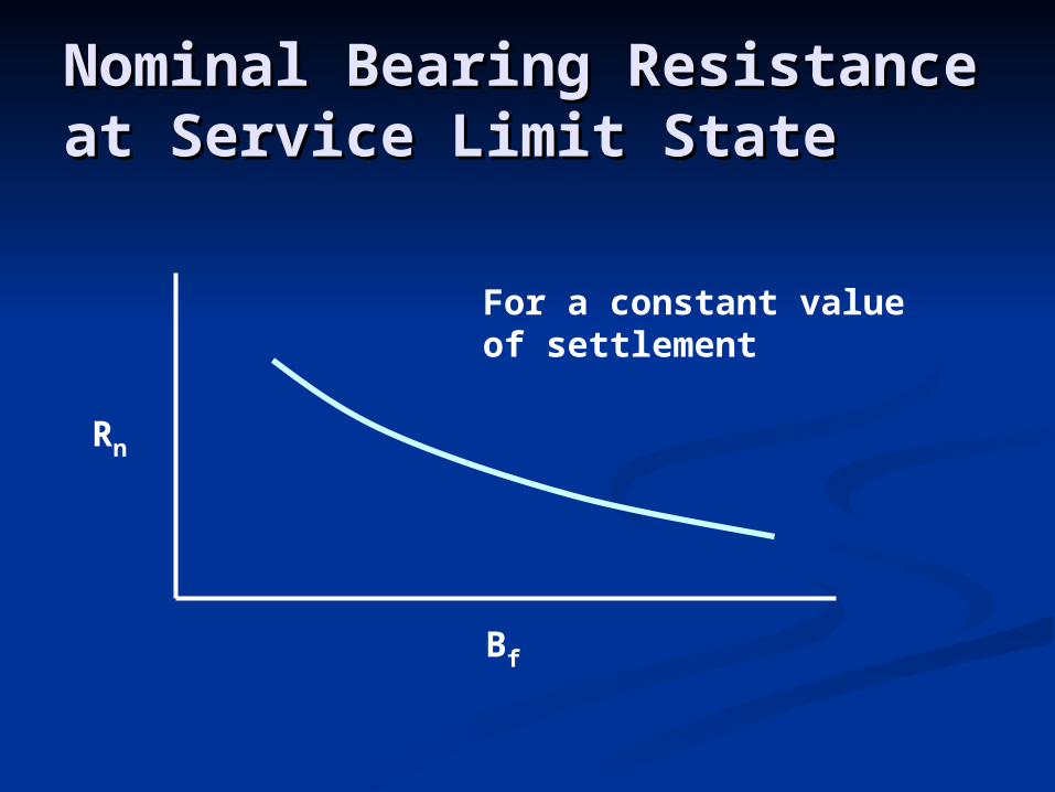
Nominal Bearing Resistance at Nominal Bearing Resistance at Service Limit StateService Limit State
Rn
Bf
For a constant valueof settlement

ML MB
PPP
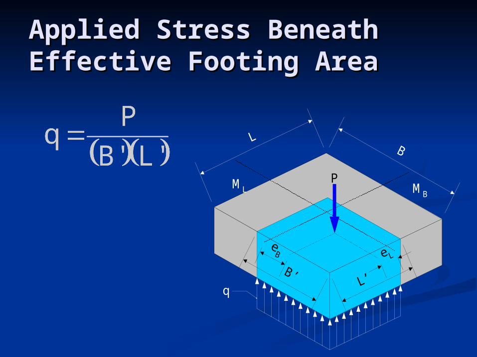
Eccentricity of Footings on SoilEccentricity of Footings on Soil
eeBB = M = MBB / P / PeeLL = M = MLL / P / P

ML MB
P
Effective Dimensions for Effective Dimensions for Footings on SoilFootings on Soil
BB′′ = B – 2e = B – 2eBB
LL′′ = L – 2e = L – 2eLL
ML MB
P
q
Applied Stress Beneath Effective Applied Stress Beneath Effective Footing AreaFooting Area
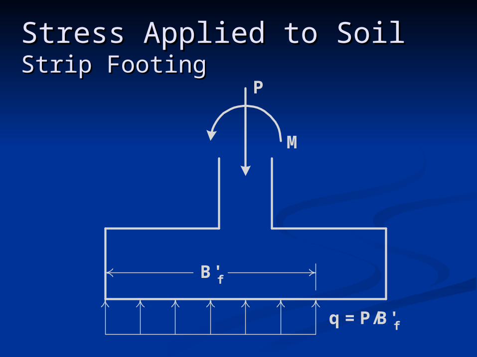
Stress Applied to SoilStress Applied to SoilStrip FootingStrip Footing
P
M
q = P/B'f
B'f
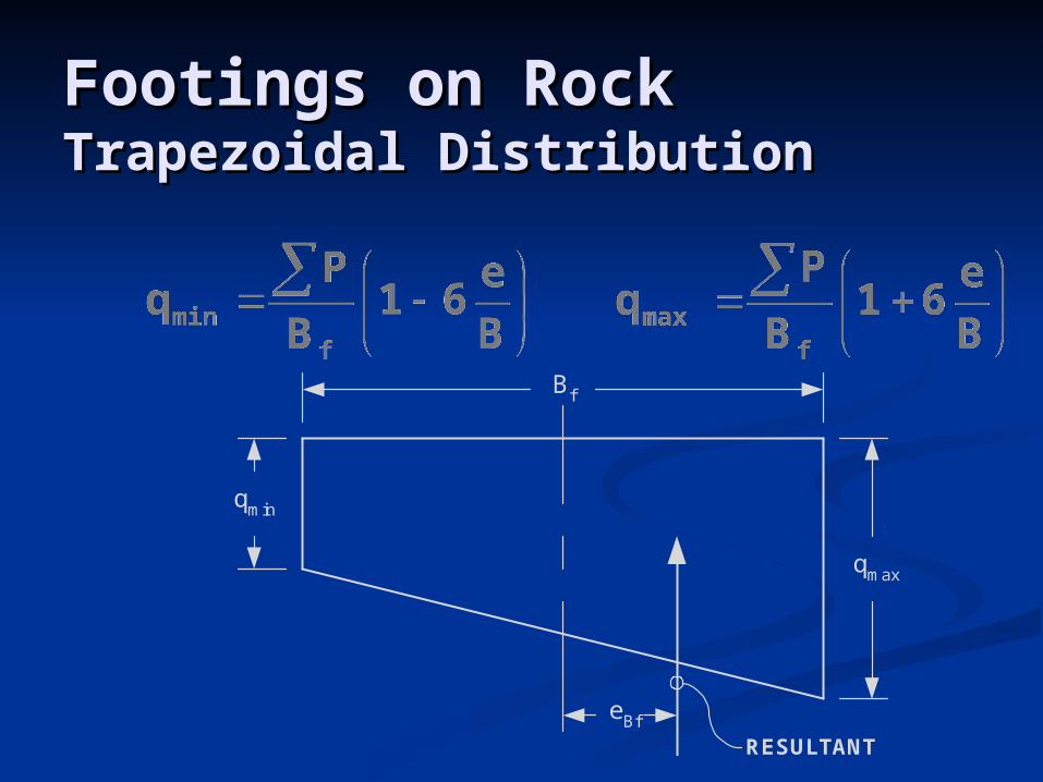
qmin
qmax
Bf
RESULTANT
eBf
Footings on RockFootings on RockTrapezoidal DistributionTrapezoidal Distribution
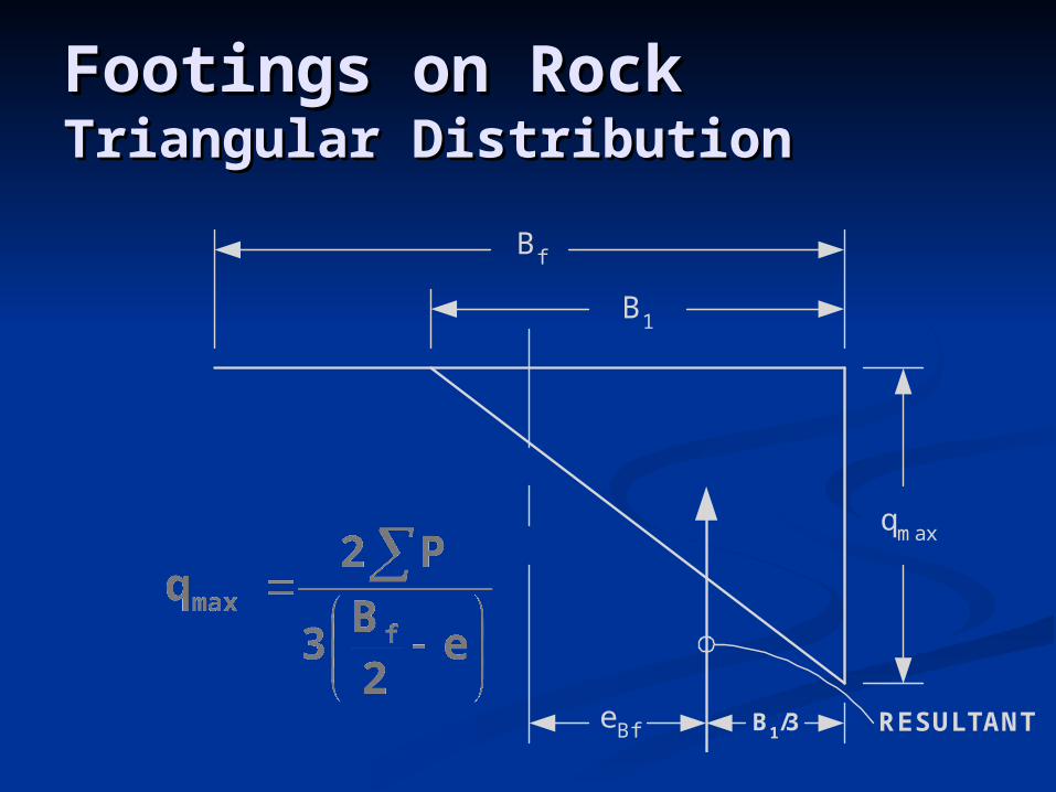
qmax
Bf
RESULTANTeBf
B1
B1/3
Footings on RockFootings on RockTriangular DistributionTriangular Distribution
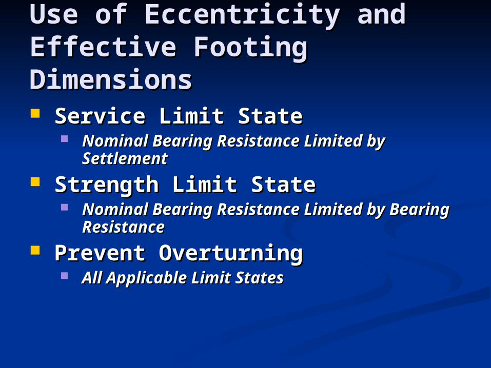
Use of Eccentricity and Effective Use of Eccentricity and Effective Footing DimensionsFooting Dimensions
Service Limit StateService Limit State Nominal Bearing Resistance Limited by Nominal Bearing Resistance Limited by
SettlementSettlement
Strength Limit StateStrength Limit State Nominal Bearing Resistance Limited by Bearing Nominal Bearing Resistance Limited by Bearing
ResistanceResistance
Prevent OverturningPrevent Overturning All Applicable Limit StatesAll Applicable Limit States
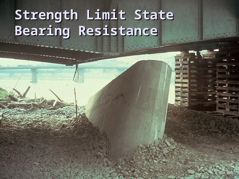
Strength Limit StateStrength Limit StateBearing ResistanceBearing Resistance

Strength Limit State Design – Strength Limit State Design – Bearing ResistanceBearing Resistance Footings on SoilFootings on Soil
Evaluate Using Conventional Bearing TheoryEvaluate Using Conventional Bearing Theory
Footings on RockFootings on Rock Evaluate Using CSIR Rock Mass Rating ProcedureEvaluate Using CSIR Rock Mass Rating Procedure
1122 22
3333
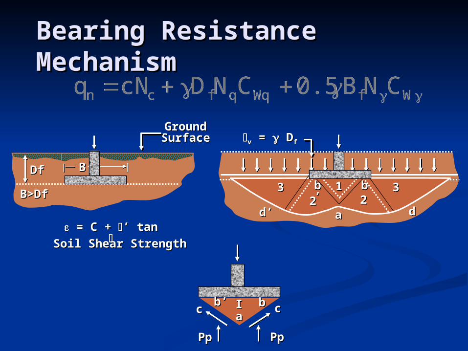
ddaad’d’ = C + = C + ’ tan ’ tan
Soil Shear StrengthSoil Shear Strength
DfDf
B>DfB>Df
BB
Ground Ground SurfaceSurface vv = = D Dff
PpPpPpPp
cccc bbaaIIb’b’
bbbb’’
Bearing Resistance MechanismBearing Resistance Mechanism

Table 10.5.5.2.1-1 Resistance Factors for Geotechnical Resistance of Shallow Foundations at the Strength Limit State
METHOD/SOIL/CONDITION RESISTANCE FACTOR
Bearing Resistance
b
Theoretical method (Munfakh, et al. (2001), in clay 0.50
Theoretical method (Munfakh, et al. (2001), in sand, using CPT
0.50
Theoretical method (Munfakh, et al. (2001), in sand, using SPT
0.45
Semi-empirical methods (Meyerhof), all soils 0.45
Footings on rock 0.45
Plate Load Test 0.55
Sliding
Precast concrete placed on sand 0.90
Cast-in-Place Concrete on sand 0.80
Cast-in-Place or precast Concrete on Clay 0.85
Soil on soil 0.90
epPassive earth pressure component of sliding resistance
0.50
Footings on RockFootings on Rock
Service Limit State – use published Service Limit State – use published presumptive bearingpresumptive bearing
Published values are Published values are allowableallowable therefore settlement-limitedtherefore settlement-limited
Procedures for computing settlement Procedures for computing settlement are availableare available

Very little guidance available for Very little guidance available for bearing resistance of rockbearing resistance of rock
Proposed Specification revisions Proposed Specification revisions provide for evaluating the cohesion and provide for evaluating the cohesion and friction angle of rock using the CSIR friction angle of rock using the CSIR Rock Mass Rating SystemRock Mass Rating System
Footings on Rock – Footings on Rock – Strength Limit StateStrength Limit State
CSIR Rock Mass Rating SystemCSIR Rock Mass Rating System
CSIR Rock Mass Rating developed for CSIR Rock Mass Rating developed for tunnel designtunnel design
Includes life safety considerations and Includes life safety considerations and therefore, margin of safetytherefore, margin of safety
Use of cohesion and friction angle Use of cohesion and friction angle therefore may be conservativetherefore may be conservative
LRFD vs. ASDLRFD vs. ASD
All modes are expressly checked at a All modes are expressly checked at a limit state in LRFDlimit state in LRFD
Eccentricity limits replace the Eccentricity limits replace the overturning Factor of Safetyoverturning Factor of Safety
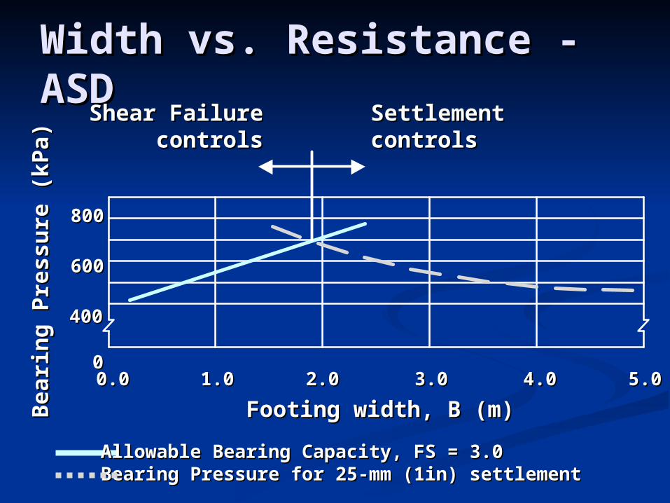
Width vs. Resistance - ASDWidth vs. Resistance - ASDSettlementSettlementcontrolscontrols
Shear FailureShear Failurecontrolscontrols
Footing width, B (m)Footing width, B (m)0.00.0 1.01.0 2.02.0 3.03.0 4.04.0 5.05.0
800800
Beari
ng
Pre
ssu
re (
kP
a)
Beari
ng
Pre
ssu
re (
kP
a)
Allowable Bearing Capacity, FS = 3.0Allowable Bearing Capacity, FS = 3.0Bearing Pressure for 25-mm (1in) settlementBearing Pressure for 25-mm (1in) settlement
600600
400400
00

Settlement vs. Bearing Settlement vs. Bearing ResistanceResistance
00
1212
N=30N=30
B, ftB, ft
qqaa,
ksf
, k
sf
N=25N=25
N=5N=5
N=20N=20
N=15N=15
N=10N=10
22 44 66 1414101088 1212
22
00
44
66
88
1010
00
1212
N=30N=30
B, ftB, ft
qqaa,
ksf
, k
sf
N=25N=25
N=5N=5
N=20N=20
N=15N=15
N=10N=10
22 44 66 1414101088 1212
22
00
44
66
88
1010
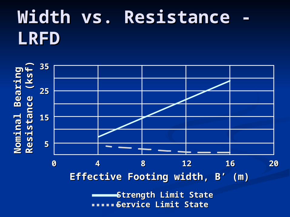
Width vs. Resistance - LRFDWidth vs. Resistance - LRFD
Effective Footing width, B’ (m)Effective Footing width, B’ (m)00 44 88 1212 1616 2020
Nom
inal B
eari
ng
N
om
inal B
eari
ng
R
esis
tan
ce (
ksf)
Resis
tan
ce (
ksf)
Strength Limit StateStrength Limit StateService Limit StateService Limit State
55
1515
2525
3535

Recommended PracticeRecommended Practice
For LRFD design of footings on soil For LRFD design of footings on soil and rock;and rock; Size footings at the Service Limit StateSize footings at the Service Limit State Check footing at all other applicable Limit StatesCheck footing at all other applicable Limit States
Settlement typically controls!Settlement typically controls!
Summary Comparison of ASD Summary Comparison of ASD and LRFD for Spread Footingsand LRFD for Spread Footings Same geotechnical theory used to Same geotechnical theory used to
compute resistances, compute resistances, howeverhowever As per Limit State concepts, As per Limit State concepts,
presentation of design presentation of design recommendations needs to be modifiedrecommendations needs to be modified

METHOD/SOIL/CONDITIONRESISTANCE
FACTOR
BearingResistance
All methods, soil and rock 0.45
Plate Load Test 0.55
Sliding Precast concrete placed on sand
0.90
Cast-in-Place Concrete on sand
0.80
Clay 0.85
Soil on soil 0.90
ep Passive earth pressure component of sliding resistance
0.50
Strength Limit State Resistance Factors