Embed Size (px)
Citation preview
WSDOT Bridge Design Manual M 23-50.17 Page 15-i June 2017
15.1 Manual Description . . . . . . . . . . . . . . . . . . . . . . . . . . . . . . . . . . . . . . . . . . . . . . . . . . . . . . .15-115.1.1 Purpose . . . . . . . . . . . . . . . . . . . . . . . . . . . . . . . . . . . . . . . . . . . . . . . . . . . . . . . . . .15-115.1.2 Specifications . . . . . . . . . . . . . . . . . . . . . . . . . . . . . . . . . . . . . . . . . . . . . . . . . . . . . .15-1
15.2 BridgeConfigurationCriteria . . . . . . . . . . . . . . . . . . . . . . . . . . . . . . . . . . . . . . . . . . . . . .15-215.2.1 General . . . . . . . . . . . . . . . . . . . . . . . . . . . . . . . . . . . . . . . . . . . . . . . . . . . . . . . . . .15-215.2.2 RailroadCrossings . . . . . . . . . . . . . . . . . . . . . . . . . . . . . . . . . . . . . . . . . . . . . . . . . .15-215.2.3 DetourStructures . . . . . . . . . . . . . . . . . . . . . . . . . . . . . . . . . . . . . . . . . . . . . . . . . . .15-315.2.4 InspectionandMaintenanceAccess . . . . . . . . . . . . . . . . . . . . . . . . . . . . . . . . . . . . . .15-315.2.5 BridgeTypes . . . . . . . . . . . . . . . . . . . . . . . . . . . . . . . . . . . . . . . . . . . . . . . . . . . . . .15-415.2.6 AestheticDesignElements . . . . . . . . . . . . . . . . . . . . . . . . . . . . . . . . . . . . . . . . . . . .15-415.2.7 ArchitecturalDesignStandards . . . . . . . . . . . . . . . . . . . . . . . . . . . . . . . . . . . . . . . . .15-515.2.8 Methods . . . . . . . . . . . . . . . . . . . . . . . . . . . . . . . . . . . . . . . . . . . . . . . . . . . . . . . . .15-515.2.9 Design-BuilderUrbanDesignTeam . . . . . . . . . . . . . . . . . . . . . . . . . . . . . . . . . . . . . .15-515.2.10 AnalysisandDesignCriteriaforStructuralWideningsandModifications . . . . . . . . . . .15-615.2.11 BridgeSecurity . . . . . . . . . . . . . . . . . . . . . . . . . . . . . . . . . . . . . . . . . . . . . . . . . . . .15-6
15.3 Load Criteria . . . . . . . . . . . . . . . . . . . . . . . . . . . . . . . . . . . . . . . . . . . . . . . . . . . . . . . . . . . .15-815.3.1 Scope . . . . . . . . . . . . . . . . . . . . . . . . . . . . . . . . . . . . . . . . . . . . . . . . . . . . . . . . . . .15-815.3.2 LoadFactorsandLoadCombinations . . . . . . . . . . . . . . . . . . . . . . . . . . . . . . . . . . . . .15-815.3.3 PermanentLoads . . . . . . . . . . . . . . . . . . . . . . . . . . . . . . . . . . . . . . . . . . . . . . . . . . .15-815.3.4 LiveLoads . . . . . . . . . . . . . . . . . . . . . . . . . . . . . . . . . . . . . . . . . . . . . . . . . . . . . . . .15-915.3.5 NoiseBarrierWalls . . . . . . . . . . . . . . . . . . . . . . . . . . . . . . . . . . . . . . . . . . . . . . . . . 15-10
15.4 SeismicDesignandRetrofit . . . . . . . . . . . . . . . . . . . . . . . . . . . . . . . . . . . . . . . . . . . . . . 15-1115.4.1 General . . . . . . . . . . . . . . . . . . . . . . . . . . . . . . . . . . . . . . . . . . . . . . . . . . . . . . . . . 15-1115.4.2 WSDOTAdditionsandModificationstoAASHTOGuideSpecifications
forLRFDSeismicBridgeDesign . . . . . . . . . . . . . . . . . . . . . . . . . . . . . . . . . . . . . . . 15-1115.4.3 SeismicDesignRequirementsforBridgeModificationsandWideningProjects . . . . . . 15-2115.4.4 SeismicRetrofittingofExistingBridges . . . . . . . . . . . . . . . . . . . . . . . . . . . . . . . . . . 15-23
15.5 Concrete Structures . . . . . . . . . . . . . . . . . . . . . . . . . . . . . . . . . . . . . . . . . . . . . . . . . . . . . 15-2515.5.1 General . . . . . . . . . . . . . . . . . . . . . . . . . . . . . . . . . . . . . . . . . . . . . . . . . . . . . . . . . 15-2515.5.2 Materials . . . . . . . . . . . . . . . . . . . . . . . . . . . . . . . . . . . . . . . . . . . . . . . . . . . . . . . . 15-2515.5.3 DesignConsiderations . . . . . . . . . . . . . . . . . . . . . . . . . . . . . . . . . . . . . . . . . . . . . . 15-2715.5.4 Superstructures . . . . . . . . . . . . . . . . . . . . . . . . . . . . . . . . . . . . . . . . . . . . . . . . . . . . 15-2815.5.5 ConcreteBridgeDecks . . . . . . . . . . . . . . . . . . . . . . . . . . . . . . . . . . . . . . . . . . . . . . 15-32
15.6 Steel Structures . . . . . . . . . . . . . . . . . . . . . . . . . . . . . . . . . . . . . . . . . . . . . . . . . . . . . . . . 15-3415.6.1 DesignConsiderations . . . . . . . . . . . . . . . . . . . . . . . . . . . . . . . . . . . . . . . . . . . . . . 15-3415.6.2 GirderBridges . . . . . . . . . . . . . . . . . . . . . . . . . . . . . . . . . . . . . . . . . . . . . . . . . . . . 15-3615.6.3 DesignofI-Girders . . . . . . . . . . . . . . . . . . . . . . . . . . . . . . . . . . . . . . . . . . . . . . . . . 15-3715.6.4 PlanDetails . . . . . . . . . . . . . . . . . . . . . . . . . . . . . . . . . . . . . . . . . . . . . . . . . . . . . . 15-42
Chapter 15 Structural Design Requirements for Design-Build Contracts Contents
Contents
Page 15-ii WSDOT Bridge Design Manual M 23-50.17 June 2017
15.7 Substructure Design . . . . . . . . . . . . . . . . . . . . . . . . . . . . . . . . . . . . . . . . . . . . . . . . . . . . 15-4515.7.1 GeneralSubstructureConsiderations . . . . . . . . . . . . . . . . . . . . . . . . . . . . . . . . . . . . 15-4515.7.2 FoundationModelingforSeismicLoads . . . . . . . . . . . . . . . . . . . . . . . . . . . . . . . . . . 15-4515.7.3 ColumnDesign . . . . . . . . . . . . . . . . . . . . . . . . . . . . . . . . . . . . . . . . . . . . . . . . . . . 15-4715.7.4 Crossbeam . . . . . . . . . . . . . . . . . . . . . . . . . . . . . . . . . . . . . . . . . . . . . . . . . . . . . . . 15-4915.7.5 AbutmentDesignandDetails . . . . . . . . . . . . . . . . . . . . . . . . . . . . . . . . . . . . . . . . . 15-4915.7.6 AbutmentWingWallsandCurtainWalls . . . . . . . . . . . . . . . . . . . . . . . . . . . . . . . . . 15-5115.7.7 FootingDesign . . . . . . . . . . . . . . . . . . . . . . . . . . . . . . . . . . . . . . . . . . . . . . . . . . . . 15-5115.7.8 Shafts . . . . . . . . . . . . . . . . . . . . . . . . . . . . . . . . . . . . . . . . . . . . . . . . . . . . . . . . . . 15-5215.7.9 PilesandPiling . . . . . . . . . . . . . . . . . . . . . . . . . . . . . . . . . . . . . . . . . . . . . . . . . . . 15-5415.7.10 Concrete-FilledSteelTubes . . . . . . . . . . . . . . . . . . . . . . . . . . . . . . . . . . . . . . . . . . . 15-55
15.8 Walls and Buried Structures . . . . . . . . . . . . . . . . . . . . . . . . . . . . . . . . . . . . . . . . . . . . . . 15-5615.8.1 RetainingWalls . . . . . . . . . . . . . . . . . . . . . . . . . . . . . . . . . . . . . . . . . . . . . . . . . . . 15-5615.8.2 NoiseBarrierWalls . . . . . . . . . . . . . . . . . . . . . . . . . . . . . . . . . . . . . . . . . . . . . . . . . 15-5915.8.3 BuriedStructures . . . . . . . . . . . . . . . . . . . . . . . . . . . . . . . . . . . . . . . . . . . . . . . . . . 15-60
15.9 Bearings and Expansion Joints . . . . . . . . . . . . . . . . . . . . . . . . . . . . . . . . . . . . . . . . . . . 15-6215.9.1 ExpansionJoints . . . . . . . . . . . . . . . . . . . . . . . . . . . . . . . . . . . . . . . . . . . . . . . . . . . 15-6215.9.2 Bearings . . . . . . . . . . . . . . . . . . . . . . . . . . . . . . . . . . . . . . . . . . . . . . . . . . . . . . . . 15-67
15.10 Signs, Barriers, Bridge Approach Slabs, and Utilities . . . . . . . . . . . . . . . . . . . . . . . . . 15-7315.10.1 SignandLuminaireSupports . . . . . . . . . . . . . . . . . . . . . . . . . . . . . . . . . . . . . . . . . . 15-7315.10.2 BridgeTrafficBarriers . . . . . . . . . . . . . . . . . . . . . . . . . . . . . . . . . . . . . . . . . . . . . . 15-8015.10.3 AtGradeConcreteBarriers . . . . . . . . . . . . . . . . . . . . . . . . . . . . . . . . . . . . . . . . . . . 15-8115.10.4 BridgeTrafficBarrierRehabilitation . . . . . . . . . . . . . . . . . . . . . . . . . . . . . . . . . . . . 15-8315.10.5 BridgeRailing . . . . . . . . . . . . . . . . . . . . . . . . . . . . . . . . . . . . . . . . . . . . . . . . . . . . 15-8415.10.6 BridgeApproachSlabs . . . . . . . . . . . . . . . . . . . . . . . . . . . . . . . . . . . . . . . . . . . . . . 15-8415.10.7 TrafficBarrieronBridgeApproachSlabs . . . . . . . . . . . . . . . . . . . . . . . . . . . . . . . . . 15-8615.10.8 UtilitiesInstalledwithNewConstruction . . . . . . . . . . . . . . . . . . . . . . . . . . . . . . . . . 15-8615.10.9 UtilityInstallationonExistingBridges . . . . . . . . . . . . . . . . . . . . . . . . . . . . . . . . . . . 15-8915.10.10 ResinBondedAnchors . . . . . . . . . . . . . . . . . . . . . . . . . . . . . . . . . . . . . . . . . . . . . . 15-8915.10.11 DrainageDesign . . . . . . . . . . . . . . . . . . . . . . . . . . . . . . . . . . . . . . . . . . . . . . . . . . . 15-90
15.11 Detailing Practices . . . . . . . . . . . . . . . . . . . . . . . . . . . . . . . . . . . . . . . . . . . . . . . . . . . . . . 15-9115.11.1 StandardPractices . . . . . . . . . . . . . . . . . . . . . . . . . . . . . . . . . . . . . . . . . . . . . . . . . 15-9115.11.2 BridgeOfficeStandardDrawingsandOfficeExamples . . . . . . . . . . . . . . . . . . . . . . . 15-9515.11.3 PlanSheets . . . . . . . . . . . . . . . . . . . . . . . . . . . . . . . . . . . . . . . . . . . . . . . . . . . . . . 15-9515.11.5 StructuralSteel . . . . . . . . . . . . . . . . . . . . . . . . . . . . . . . . . . . . . . . . . . . . . . . . . . . . 15-9715.11.6 AluminumSectionDesignations . . . . . . . . . . . . . . . . . . . . . . . . . . . . . . . . . . . . . . . 15-9915.11.7 Abbreviations . . . . . . . . . . . . . . . . . . . . . . . . . . . . . . . . . . . . . . . . . . . . . . . . . . . . . 15-99
15.12 Bridge Load Rating . . . . . . . . . . . . . . . . . . . . . . . . . . . . . . . . . . . . . . . . . . . . . . . . . . . . . 15-10015.12.1 General . . . . . . . . . . . . . . . . . . . . . . . . . . . . . . . . . . . . . . . . . . . . . . . . . . . . . . . . 15-10015.12.2 LoadRatingSoftware . . . . . . . . . . . . . . . . . . . . . . . . . . . . . . . . . . . . . . . . . . . . . . 15-100
15.99 References . . . . . . . . . . . . . . . . . . . . . . . . . . . . . . . . . . . . . . . . . . . . . . . . . . . . . . . . . . . 15-101
WSDOT Bridge Design Manual M 23-50.17 Page 15-1 June 2017
Structural Design Chapter 15 Requirements for Design-Build Contracts
15.1 Manual Description15.1.1 Purpose
ThischapterprovidesthecontractualrequirementsforstructuraldesignofWSDOTprojectsthatsupersedeAASHTOLRFD Bridge Design Specifications(LRFD)andAASHTOGuide Specifications for LRFD Seismic Bridge Design (SEISMIC).
15.1.2 SpecificationsThismanualandthefollowingAASHTOSpecificationsarethefoundationdesigncriteriaanddesignpracticedocumentsusedtodesignhighwaybridgesandstructuresinWashingtonState:• AASHTOLRFD• AASHTOSEISMIC• WSDOTStandard Plans M21-01–A-50SeriesStandardPlansforEmbankmentGeometryatBridgeEnds
Structural Design Requirements for Design-Build Contracts Chapter 15
Page 15-2 WSDOT Bridge Design Manual M 23-50.17 June 2017
15.2 BridgeConfigurationCriteria15.2.1 General
A. Bridge Redundancy
BridgesubstructureshallhavethefollowingminimumnumberofcolumnstobeconsideredtoprovideconventionallevelsofredundancyinaccordancewithAASHTOLRFD Bridge Design Specification Section1.3.4:• Onecolumnminimumforroadwaywidths40′wideandunder.• Twocolumnsminimumforroadwaywidthsover40′to60′.• Threecolumnsminimumforroadwaywidthsover60′.
BridgesuperstructureshallhavethefollowingminimumnumberofwebstobeconsideredtoprovideconventionallevelsofredundancyinaccordancewithAASHTOLRFD Bridge Design SpecificationSection1.3.4:• Threewebsminimumforroadwaywidths32′andunder.• Fourwebsminimumforroadwaywidthsover32′.SeeBridgeStandardDrawing2.3-A2-1fordetails.
B. Bridge Deck Drainage
Roadwayandbridgedeckprofilesshallbeadjustedasmuchaspossibletoavoidhavingbridgedrainsonthebridge.Ifbridgegeometryissuchthatdrainsarerequired,thenumberofdrainsshouldbeminimizedasmuchaspossiblewhilestillprovidingabridgedeckdrainagedesignthatmeetsrequiredstandards.Thebridgedrainassemblyandsystemshallbedesignedforlowmaintenance.
15.2.2 Railroad CrossingsA. Horizontal Clearances
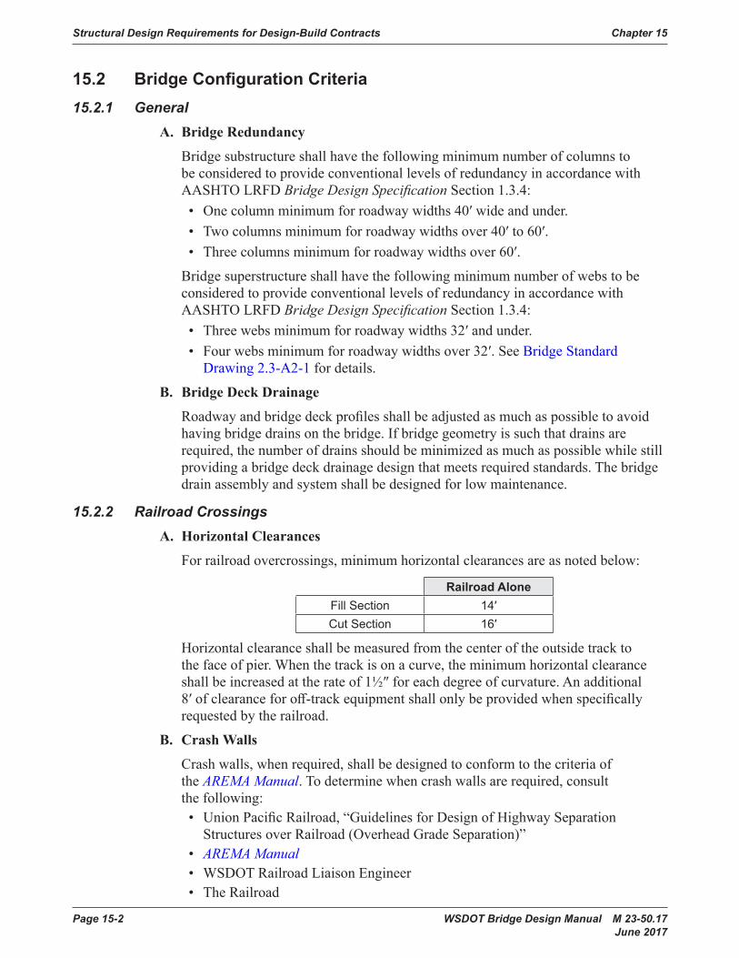
Forrailroadovercrossings,minimumhorizontalclearancesareasnotedbelow:
Railroad AloneFill Section 14′Cut Section 16′
Horizontalclearanceshallbemeasuredfromthecenteroftheoutsidetracktothefaceofpier.Whenthetrackisonacurve,theminimumhorizontalclearanceshallbeincreasedattherateof1½″foreachdegreeofcurvature.Anadditional8′ofclearanceforoff-trackequipmentshallonlybeprovidedwhenspecificallyrequestedbytherailroad.
B. Crash Walls
Crashwalls,whenrequired,shallbedesignedtoconformtothecriteriaoftheAREMA Manual.Todeterminewhencrashwallsarerequired,consultthefollowing:• UnionPacificRailroad,“GuidelinesforDesignofHighwaySeparationStructuresoverRailroad(OverheadGradeSeparation)”
• AREMA Manual • WSDOTRailroadLiaisonEngineer• TheRailroad
Chapter 15 Structural Design Requirements for Design-Build Contracts
WSDOT Bridge Design Manual M 23-50.17 Page 15-3 June 2017
C. Substructure
Forhighwayoverrailwaygradeseparations,thetopoffootingsforbridgepiersorretainingwallsadjacenttorailroadtracksshallbe2′ormorebelowtheelevationofthetopoftieandshallnothavelessthan2′ofcoverfromthefinishedground.Thefootingfaceshallnotbecloserthan10′tothecenterofthetrack.
15.2.3 Detour StructuresA. Live Load
See Section3.4
B. DetourbridgetrafficbarriershallbedesignedtomeettheapplicableAASHTOLRFD criteria.
15.2.4 Inspection and Maintenance AccessA. General
Bridgesshallbeconfiguredtoallowinspectorsdirectaccesstobearings,andaccesstowithin3-feetofsuperstructuresurfaces.SeealsoFigure2.3.11-1forunder-bridge-inspection-truckclearancerequirements.
B. Bearings
Adequateclearanceformaintenanceandinspectionofbearingsshallbeprovided.Theclearanceshallbeadequatetoinspect,removeandreplacethebearings.
Jackingpointsshallbeprovidedforbearingreplacement.Jackingpointsshallbedesignedtosupport200percentofthecalculatedliftingload.
C. Safety Cables and Anchors
Built-upplategirderbridgeswithgirders5-feetdeeporgreaterindepthshallbedetailedwithsafetycablesforinspectorswalkingthebottomflanges.Atlargegussetplatelocationsontrussbridges(3-feetwideorwider),cablesorlanyardanchorsshallbeplacedontheinsidefaceofthetrusssoinspectorscanutilizebottomlateralgussetplatestostandonwhiletraversingaroundthemaintrussgussetplates.
D. AbutmentSlopes
Slopesinfrontofabutmentsshallprovideenoughoverheadclearancetothebottomofthesuperstructuretoaccessbearingsforinspectionandpossiblereplacement(3-feetminimumforgirdertypebridgesand5-feetminimumforconcreteslabs).
E. Access and Lighting
1. Concrete Box and Prestressed Concrete TubGirders
See Section5.2.6fordesigncriteria.
2. CompositeSteelBoxGirders
See Section6.4.9fordesigncriteria.
Structural Design Requirements for Design-Build Contracts Chapter 15
Page 15-4 WSDOT Bridge Design Manual M 23-50.17 June 2017
3. AccessDoors,Lighting,ReceptaclesandPenetrations
AllAccessdoorsshallhaveaminimum2′-6″diameteror2′-6″squareclearopening.Lockboxlatchesshallbeinstalledonallaccessdoorsaccessiblefromgroundlevel.Accesshatchesshallswingintotheboxgirdersandshallbeplacedatlocationsthatdonotimpacttraffic.LightingandreceptaclerequirementsshallbeinaccordancewithWSDOT Design Manual Chapter1040.AirventsshallbeinaccordancewithFigures5.2.6-1and5.2.6-2.
Boxgirderpenetrations(ventsanddrainholes)greaterthanoneinchindiameterthroughtheexteriorshallbecoveredwithgalvanizedwiremeshscreentopreventverminandbirdsfromaccessingtheinterioroftheboxgirder.Thewiresshallhaveamaximumspacingof¼inchinbothdirections.
15.2.5 Bridge TypesBridgesshallconformtothefollowingsuperstructuredepth-to-spanratiosbasedonpastWSDOTexperience,supersedingAASHTOLRFDSection2.52.6.3.
TheoptionalliveloaddeflectionlimitsofAASHTOLRFDSections3.6.1.3.2and2.5.2.6.2shallbesatisfied.
Forbothsimpleandcontinuousspans,thespanlengthisthehorizontaldistancebetweencenterlinesofbearings.
RefertoSection2.2.4forsuperstructuredepthrequirementsforinspectionandmaintenanceaccess.
FortherequiredminimumdepthtospanratiosseeSection2.4.1.
15.2.6 Aesthetic Design ElementsTheprimarygoaloftheaestheticdesignistobuildvisualcompatibilitybetweenthenewelementsandtheircurrentsurroundings.Theexistingelements,alongwithproposedandexistingstructures,typicallyestablishanidentifiablevisualcharacteristic.Theseexistingelementssuchaslightingfixtures,railingsstreethardware,constructionmaterials,colors,andfinishes,aretobeincludedasanintegralpartofthenewconstructionprogram.Examplesofnewelementsmayincludebutarenotlimitedto:• Bridgestructuretype• Bridgestructuremajorelementssuchaspierandcrossbeamform• Bridgestructureminorelementssuchasrailingsandlightstandards• Retainingwallmaterials,configurationandfinishes• Noisewallmaterial,configurationandfinishes:asviewedfromthecorridor• Noisewalls:asviewedfromtheneighborhoods• Vistaviewpoints• Medianandroadsideplantingareas• Colorselection• OpportunitiesforcommunityfundedartinaccordancewithDesign Manual Chapter950
Chapter 15 Structural Design Requirements for Design-Build Contracts
WSDOT Bridge Design Manual M 23-50.17 Page 15-5 June 2017
SomedesignelementsareplannedtobefunctionallyandvisuallyconsistentwithfeaturesintheProject’sadjacentstructures.Otherelementsbenefitbyretainingflexibilitywithinaconsistentpaletteofmaterials,colors,anddesignformsinordertoprovidethedesign-build-processflexibilityindevelopingpotentialsolution.
ThefinaldesignandconfigurationoftheseProjectfeaturesandotherfunctionalcomponentswillrequireongoingcommunication,review,andcoordinationbetweenthedesign-buildContractor’sdesignteamandWSDOT’sreviewteam.
15.2.7 Architectural Design StandardsTheRFPdocumentswillincludearchitecturalstandards.ThesewillaccommodatethefunctionalrequirementsofthepreferreddesignsolutionaswellasaddressthecontextualconditionsoftheProjectarea.Theywillbesensitivetocorridorcontinuityaswellasthescale,characterandtextureofthearea.
ThestandardswillprovideareferencefortheProject’scontextsensitivedesignandpassalongthefindingsoftheurbandesignanalysisconductedduringtheProject’splanningandearlydesignphases.ThestandardsdescribetheProject’surbandesignfeaturesandaideinthecreationofanattractivefacilitythatwillbefunctional,maintainableovertime,aswellasaddtothearea’svisualcharacter.
Dependingontheprojectcomplexity,thestandardsmaybehighlydetailedandprescriptiveortheymaybemoregeneralinnature,suchasasimplelistofcriteria.
15.2.8 MethodsThedesign-buildershallcomplywiththearchitecturalstandards.Thedesign-buildershallalsoberesponsivetotheexistingurbandesigndocumentsintheadjacentcorridors.
Thedesign-buildershallemploythehigheststandardofcarebyimplementingnationalbestpracticesinurbandesign.Themethodsshallinclude,butnotlimitedto,suchtechniquesaContextSensitiveDesign(CSS)andCrimePreventionThroughEnvironmentalDesign(CEPTED).
15.2.9 Design-Builder Urban Design TeamWhererequiredintheRFP,thedesign-buildershallincludeaestheticdesignteammemberresources.Thisshallincludeanexperiencedurbandesignercapableofworkingwithotherteammembersandtoaddressfinalcontextsensitivedesignissues,constructiondetails,andspecialprojectdesignfeatures.Theurbandesignershallbeanarchitectwithurbanprojectexperience.
ThearchitectshallbelicensedintheStateofWashingtonandberesponsibleforthecoordinationanddevelopmentoftheproject’sarchitecturalcomponents.Preferenceshallbegiventoateamwithanarchitectexperiencedinbridgearchitecture.PreferenceshallalsobegiventoteamswherethearchitecthasacurrentstandingwithprofessionalorganizationssuchastheAmericanInstituteofArchitects(AIA)ortheAmericanInstituteofCityPlanners(AICP).Thearchitectshallsealtheapplicabledesigndocuments.
Structural Design Requirements for Design-Build Contracts Chapter 15
Page 15-6 WSDOT Bridge Design Manual M 23-50.17 June 2017
WhenrequiredbytheRFP,andinordertoassureconsistencywiththeRFParchitecturaldesignstandards,thedesign-buildershallformanUrbanDesignTeam.Theteamshallconsistof,asaminimum,adesignbuilderprojecturbandesignmanager,aWSDOTBridgeandStructuresOfficeStructuresEngineer,theWSDOTStateBridgeandStructuresArchitectandtheRegionorHQPrincipalLandscapeArchitect.
15.2.10 AnalysisandDesignCriteriaforStructuralWideningsandModificationsThewideningofabridgeshallbeofasimilarsuperstructuretypeastheexisting.Theoverallappearanceandgeometricaldimensionsofthewideningshallbethesameorascloseaspossibletothoseoftheexistingstructure.Materialsusedintheconstructionofthewideningshallhavethesamethermalandelasticpropertiesasthematerialsintheoriginalstructure.Prestressedconcretegirdersmaybeusedtowidenexistingcast-in-placeconcretestructures.
Themembersofthewideningshallbeproportionedtoprovidesimilarlongitudinalandtransverseloaddistributioncharacteristicsastheexistingstructure.
Differentialsettlementbetweenthenewandexistingstructuresshallbetakenintoaccount.
Thedesignofthewideningshallconformtocurrentstandardsandnotthestandardsusedtodesignandconstructtheexistingstructure.Thestrengthoftheexistingstructureshallbecheckedutilizingcurrentdesignstandards.Existingcomponentsshallbestrengthenedasnecessarysothattheircapacity/demandratiosarenotworsened.SeismicdesignofbridgewideningsshallbeinaccordancewithSection4.3.
Diaphragmsforthewideningshallcoincidewithandbeparalleltotheexistingdiaphragms.
Falseworkforthewideningshallbesupportedfromtheexistingstructureifthewideningdoesnotrequireadditionalgirdersorsubstructure.Otherwise,falseworkforthewideningshallnotbesupportedfromtheexistingstructure.
Ifthewideningrequiresadditionalgirdersorsubstructure,aclosurestripshallbeprovided.Allfalseworksupportingthewideningshallbereleasedpriortoplacingconcreteintheclosurestrip.Formworksupportingtheclosurestripshallbesupportedfromtheexistingstructureandthewidening.
15.2.11 Bridge SecurityA. General
WhererequiredintheRFP,newbridgesshallbedesignedforsecurity.Bridgeabutmentsinparticularshallbedesignedtodeterinappropriatepublicuseandaccessbyillegalurbancampers.
TheDesign-BuildContractorshallcoordinatewiththeprojecturbandesignteamtoidentifydeterrencestrategies.TheprinciplesofCPTED(CrimePreventionThroughEnvironmentalDesign)shallbeemployedwithtwostrategicoptions.Thefirststrategyemploysnaturalsurveillanceandterritorialreinforcement.Forconditionswherethefirststrategyisnotfeasible,thenasecondstrategyshallbeprovided.Thesecondstrategyprovideshardarmoring,suchassecurityfences.

Chapter 15 Structural Design Requirements for Design-Build Contracts
WSDOT Bridge Design Manual M 23-50.17 Page 15-7 June 2017
B. NaturalSurveillanceandTerritorialReinforcement
Thenaturalsurveillanceandterritorialreinforcementstrategyshallbeprovidedthroughthefollowing:
1. Thedistancefromthetopofabutmentwalltothefinishedgradeatthefaceofabutmentshallnotbelessthan10feetinheightand,
2. Horizontalgradedlandformshelvesattheabutmentfacebeneathsuperstructuresshallbeomittedand,
3. Alcovespaceswithintheabutment-superstructureinterfaceshallbeomittedand,
4. Unobstructedviewsforlawenforcementsurveillanceshallbeprovided.
C. HardArmoring
Thehardarmoringstrategyshallconsistofoneofthefollowingoracombinationofboth:
1. Asecurityfencesystemwithananti-cut,anti-climb,galvanizedsteelweldedwiremeshfabric.Thesteelweldedwiremeshfabricshallhaveaminimumwirespacingof½inchforhorizontalelementsand3inchesverticalelements.Theminimumwirediametershallbe0.162inch(8gauge)steelweldedwiremesh.ThefencesystemshallhavethecomponentsshowninFigure2.8.3-2. Thebridgesecurityfenceshallnotbeconnectiontothebridgesuperstructure.Thesecurityfencemaybeattachedtothebridgeabutment,curtainwalls,girderseatsorretainingwalls.
2. Curtainwallsmaybeusedinlieuofasecurityfencesystem.Castinplaceconcrete,precastconcrete,orconcretemasonryunitmaterialsmaybeconstructedascurtainwallsprovidedtheymeettheprojecturbandesigngoals.Figure2.8.3-1showsaschematicviewofthecurtainwalloption.
Structural Design Requirements for Design-Build Contracts Chapter 15
Page 15-8 WSDOT Bridge Design Manual M 23-50.17 June 2017
15.3 Load Criteria15.3.1 Scope
AASHTOLRFDshallbetheminimumdesigncriteriausedforallprojects.Additionalrequirements,exceptions,anddeviationsfromAASHTOLRFDrequirementsarecontainedherein.
15.3.2 Load Factors and Load CombinationsAvalueof1.0shallbeusedforhiinEquation3.4.1-1ofAASHTOLRFDexceptforthedesignofcolumnswhenaminimumvalueofgiisrequiredbyArticle3.4.1ofAASHTOLRFD.Insuchacase,hishallbe0.95.
StrengthIVloadcombinationshallnotbeusedforfoundationdesign.Forfoundationdesign,loadsshallbefactoredafterdistributionthroughstructuralanalysisormodeling.
ThedesignliveloadfactorfortheServiceIIILimitStateloadcombinationshallbeasfollows:
gLL=0.8whentherequirementsofSections5.6.1and5.6.2aresatisfiedandstressanalysisisbasedongrosssectionproperties.
gLL=1.0whentherequirementsofSections5.6.1and5.6.2aresatisfiedandstressanalysisisbasedontransformedsectionproperties.
InspecialcasesthatdeviatefromtherequirementsofSections5.6.1and5.6.2andhavebeenapprovedbytheWSDOTBridgeDesignEngineer,gLL,shallbeasspecifiedintheAASHTOLRFD.
TheServiceIIIliveloadfactorforloadratingshallbe1.0.
TheliveloadfactorforExtremeEvent-ILimitStateshallbe0.5.Thebaseconstructiontemperatureshallbetakenas64°FforthedeterminationofTemperatureLoad.
TheLoadFactorsforPermanentLoadsDuetoSuperimposedDeformationsareprovidedinTable3.53.Table3.5-3replacesTable3.4.1-3ofAASHTOLRFD.
15.3.3 Permanent LoadsThedesignunitweightsofcommonpermanentloadsshallbeasshowninTable3.8-1.
A. FutureDeckOverlayRequirement
StructuresthatwillbeconstructedwithdeckprotectionSystem1or4shallbedesignedtoaccountfora2″thickHMAoverlayplaceduniformlyovertheentiredeckarea.Thedesignneednotaccountfortheweightofthe2″thickHMAoverlaywithinthedeckareacoveredbyappurtenancessuchas,butnotlimitedto,sidewalksandtrafficbarriers,whichhaveadeadweightinexcessofthe2″thickHMAoverlay.

Chapter 15 Structural Design Requirements for Design-Build Contracts
WSDOT Bridge Design Manual M 23-50.17 Page 15-9 June 2017
15.3.4 Live LoadsA. Design Live Load
Thedesignliveloadshallbe:• Fornewbridgesandbridgesthataremodifiedinsuchawaytoincludenewsubstructureelements–LiveloadinaccordancewithAASHTOLRFD
• Forbridgesmodifiedinsuchawaythatdonotincludenewsubstructureelements–Liveloadcriteriaoftheoriginaldesign
• Forbridgesusedfortemporarydetourorothertemporarypurposes–minimum75percentofHL-93liveloadinaccordancewithAASHTOLRFD
TheapplicationofdesignvehicularliveloadsshallbeasspecifiedinAASHTOLRFDSection3.6.1.3.Thedesigntandem,or“lowboy”,definedinLRFDSectionC3.6.1.1shallbeincludedinthedesignvehicularliveload.
• TheeffectofonedesigntandemcombinedwiththeeffectofthedesignlaneloadspecifiedinLRFDArticle3.6.1.2.4and,fornegativemomentbetweenthepointsofcontraflexureunderauniformloadonallspansandreactionsatinteriorsupports,shallbeinvestigatedadualdesigntandemspacedfrom26.0feetto40.0feetapart,measuredbetweenthetrailingaxleoftheleadvehicleandtheleadaxleofthetrailingvehicle,combinedwiththedesignlaneload.Forthepurposeofthisarticle,thepairsofthedesigntandemshallbeplacedinadjacentspansinsuchpositiontoproducemaximumforceeffect.Axlesofthedesigntandemthatdonotcontributetotheextremeforceeffectunderconsiderationshallbeneglected.
B. LiveLoadDeflectionEvaluation
Article2.5.2.6.2oftheAASHTOLRFDismandatoryinitsentirety.
C. DistributiontoSuperstructure
1. Crosssectionsa,e,k,andalsoiandjifsufficientlyconnectedtoactasaunitfromAASHTOLRFD Table 4.6.2.2.1-1
Theliveloaddistributionfactorshallbeasfollows:• Forexteriorgirderdesignwithslabcantileverlengthequalorlessthan40percentoftheadjacentinteriorgirderspacing,usetheliveloaddistributionfactorfortheadjacentinteriorgirder.Theslabcantileverlengthisdefinedasthedistancefromthecenterlineoftheexteriorgirdertotheedgeoftheslab.
• Forexteriorgirderdesignwithslabcantileverlengthexceeding40percentoftheadjacentinteriorgirderspacing,usetheleverrulewiththemultiplepresencefactorof1.0forsinglelanetodeterminetheliveloaddistribution.Theliveloadusedtodesigntheexteriorgirdershallnotbelessthantheliveloadusedfortheadjacentinteriorgirder.
Structural Design Requirements for Design-Build Contracts Chapter 15
Page 15-10 WSDOT Bridge Design Manual M 23-50.17 June 2017
• TherigidcrosssectionanalysisdescribedinAASHTOLRFDSectionC4.6.2.2.2dshallnotbeusedtodetermineliveloaddistributionunlessitcanbedemonstratedthattheeffectivenessofdiaphragmsonthelateraldistributionofvehicularliveloadcausesthecrosssectionofthestructuretodeflectandrotateasarigidcrosssection.
2. CrosssectionTypedfromAASHTOLRFDTable4.6.2.2.1-1
Thistypeofcrosssectionshallbedesignedasasingleunit.TheliveloadforceeffectsshallbethatofasinglelaneofliveloadmultipliedbytheproductoftheliveloaddistributionfactorforinteriorgirderscomputedinaccordancewithAASHTOLRFDandthetotalnumberofwebsinthecrosssection.ThecorrectionfactorforliveloaddistributionforskewedsupportsasspecifiedinAASHTOLRFDTables4.6.2.2.2e-1and4.6.2.2.3c1forshearshallapply.
3. Distribution to Substructure
Thenumberoftrafficlanestobeusedinthesubstructuredesignshallbedeterminedbydividingtheentireroadwayslabwidthby12-feet.Nofractionallanesshallbeused.Bridgedeckwidthsoflessthan24feetshallhaveaminimumoftwodesignlanes.
4. DistributiontoCrossbeam
Thedesignandloadratingshallbedistributedtothesubstructurebyplacingwheellinereactionsinalaneconfigurationthatgeneratesthemaximumforceeffectsinthesubstructure.LiveloadsareconsideredtoactdirectlyonthesubstructurewithoutfurtherdistributionthroughthesuperstructureasillustratedinFigure3.9-1.
Forsteelandprestressedconcretesuperstructurewheretheliveloadistransferredtosubstructurethroughbearings,crossframesordiaphragms,thegirderreactionmaybeusedforsubstructuredesign.
15.3.5 Noise Barrier WallsWindonNoiseWallsshallbeasspecifiedinAASHTOLRFDSections3.8.1,3.8.1.2.4,and15.8.2.
WSDOT Bridge Design Manual M 23-50.17 Page 15-11 June 2017
15.4 SeismicDesignandRetrofit15.4.1 General
ThischapterandtheAASHTO SEISMICarethefoundationseismicdesigncriteriadocumentsusedtodesignhighwaybridgesinWashingtonState.
ThischaptersupplementsandsupersedestheAASHTOLRFDbyprovidingWSDOTseismicdesigncriteria,policyandpractice.
TheimportanceclassificationsforallhighwaybridgesinWashingtonStateareclassifiedas“Normal”exceptforspecialmajorbridges.Specialmajorbridgesfittingtheclassificationsofeither“Critical”or“Essential”willbesodesignatedintheRFP.
15.4.2 WSDOTAdditionsandModificationstoAASHTOGuideSpecificationsfor LRFD Seismic Bridge Design
WSDOTmodificationstotheAASHTOSEISMICareasfollows:
A. Definitions
GuideSpecificationsArticle2
Reviseexistingdefinitionsandaddnewdefinitionsasfollows:• Oversized Pile Shaft Adrilledshaftfoundationthatislargerindiameterthanthesupportedcolumnandhasareinforcingcagelargerthanandindependentofthecolumn’sreinforcementcage.ThesizeoftheshaftshallbeinaccordancewithSection7.8.2.
• Owner Personoragencyhavingjurisdictionoverthebridge.ForWSDOTprojects,regardlessofdeliverymethod,theterm“Owner”intheseGuideSpecificationsshallbetheWSDOTBridgeDesignEngineerand/ortheWSDOTGeotechnicalEngineer.
B. EarthquakeResistingSystems(ERS)RequirementsforSeismicDesignCategories(SDCs)C and D
GuideSpecificationsArticle3.3
WSDOTGlobalSeismicDesignStrategies:• Type1 DuctileSubstructurewithEssentiallyElasticSuperstructure.Thiscategoryispermissible.
• Type2 EssentiallyElasticSubstructurewithaDuctileSuperstructure.Thiscategoryisnotpermissible.
• Type3 ElasticSuperstructureandSubstructurewithaFusingMechanismBetweentheTwo.Thiscategoryisnotpermissible.
Structural Design Requirements for Design-Build Contracts Chapter 15
Page 15-12 WSDOT Bridge Design Manual M 23-50.17 June 2017
ForType1ERSforSDCCorD,ifcolumnsorpierwallsareconsideredanintegralpartoftheenergy-dissipatingsystembutremainelasticatthedemanddisplacement,theforcestouseforcapacitydesignofothercomponentsshallbeaminimumof1.2timestheelasticforcesresultingfromthedemanddisplacementinlieuoftheforcesobtainedfromoverstrengthplastichinginganalysis.Becausemaximumlimitinginertialforcesprovidedbyyieldingelementsactingataplasticmechanismlevelisnoteffectiveinthecaseofelasticdesign,thefollowingconstraintsareimposed.
1. Unlessananalysisthatconsidersredistributionofinternalstructureforcesduetoinelasticactionisperformed,allsubstructureunitsoftheframeunderconsiderationandofanyadjacentframesthatmaytransferinertialforcestotheframeinquestionshallremainelasticatthedesigngroundmotiondemand.
2. Effectivemembersectionpropertiesshallbeconsistentwiththeforcelevelsexpectedwithinthebridgesystem.Reinforcedconcretecolumnsandpierwallsshallbeanalyzedusingcrackedsectionproperties.ForthispurposeinabsenceofbetterinformationorestimatedbyFigure5.6.2-1,amomentofinertiaequaltoone-halfthatoftheuncrackedsectionshallbeused.
3. Foundationmodelingshallbeestablishedsuchthatuncertaintiesinmodelingwillnotcausetheinternalforcesofanyelementsunderconsiderationtoincreasebymorethan10percent.
4. Whensite-specificgroundresponseanalysisisperformed,theresponsespectrumordinatesshallbeselectedsuchthatuncertaintieswillnotcausetheinternalforcesofanyelementsunderconsiderationtoincreasebymorethan10percent.
5. Thermal,shrinkage,prestressorotherforcesthatmaybepresentinthestructureatthetimeofanearthquakeshallbeconsideredtoactinasensethatisleastfavorabletotheseismicloadcombinationunderinvestigation.
6. P-Deltaeffectsshallbeassessedusingtheresistanceoftheframeinquestionatthedeflectioncausedbythedesigngroundmotion.
7. Jointsheareffectsshallbeassessedwithaminimumofthecalculatedelasticinternalforcesappliedtothejoint.
8. DetailingasnormallyrequiredineitherSDCCorD,asappropriate,shallbeprovided.
Useofexpectedmaterialstrengthsforthedeterminationofmemberstrengthsforelasticresponseofmembersispermitted.
TheuseofelasticdesigninlieuofoverstrengthplastichingingforcesforcapacityprotectiondescribedaboveshallonlybeconsideredifdesignerdemonstratesthatcapacitydesignofArticle4.11oftheAASHTOGuide Specifications for LRFD Bridge Seismic Designisnotfeasibleduetogeotechnicalorstructuralreasons.
Type3ERSmaybeconsideredonlyifType1strategyisnotsuitableandType3strategyhasbeendeemednecessaryforaccommodatingseismicloads.IsolationbearingsshallbedesignedinaccordancewiththeAASHTO Guide Specifications for Seismic Isolation.IsolationbearingsshallconformtoSection9.3.
Chapter 15 Structural Design Requirements for Design-Build Contracts
WSDOT Bridge Design Manual M 23-50.17 Page 15-13 June 2017
LimitationsontheuseofERSandEREareshowninFigures4.2.2-1,4.2.2-2,4.2.2-3,and4.2.3-4.• Figure4.2.2-2Type6,connectionwithmomentreducingdetailshouldonlybeusedatcolumnbaseifprovednecessaryforfoundationdesign.AfixedconnectionatbaseofcolumnremainsthepreferredoptionforWSDOTbridges.
• Thedesigncriteriaforcolumnbasewithmomentreducingdetailshallconsiderallapplicableloadsatservice,strength,andextremeeventlimitstates.
• 4.2.2-3Types6and8arenotpermissiblefornon-liquefiedconfigurationandpermissibleforliquefiedconfiguration.
C. SeismicGroundShakingHazard
GuideSpecificationsArticle3.4
ForbridgesthatareconsideredcriticaloressentialornormalbridgeswithasiteClassF,theseismicgroundshakinghazardshallbedeterminedinaccordancewiththesitespecificprocedureinArticle3.4.3oftheAASHTOSEISMIC.
IncaseswherethesitecoefficientsusedtoadjustmappedvaluesofdesigngroundmotionforlocalconditionsareinappropriatetodeterminethedesignspectrainaccordancewithgeneralprocedureofArticle3.4.1(suchastheperiodattheendofconstantdesignspectralaccelerationplateau(Ts)isgreaterthan1.0secondortheperiodatthebeginningofconstantdesignspectralaccelerationplateau(To)islessthan0.2second),asite-specificgroundmotionresponseanalysisshallbeperformed.
ThespectralresponseparametersshallbedeterminedusingUSGS2014 Seismic Hazard Maps and Site Coefficients definedinSection4.2.3.
D. SelectionofSeismicDesignCategory(SDC)
GuideSpecificationsArticle3.5
ApushoveranalysisshallbeusedtodeterminedisplacementcapacityforbothSDCsCandD.
E. TemporaryandStagedConstruction
GuideSpecificationsArticle3.6
Forbridgesthataredesignedforareducedseismicdemand,thecontractplansshalleitherincludeastatementthatclearlyindicatesthatthebridgewasdesignedastemporaryusingareducedseismicdemandorshowtheAccelerationResponseSpectrum(ARS)usedfordesign.Noliquefactionassessmentrequiredfortemporarybridges.
F. Load and Resistance Factors
GuideSpecificationsArticle3.7
Useloadfactorsof1.0forallpermanentloads.Theloadfactorforliveloadshallbe0.0whenpushoveranalysisisusedtodeterminethedisplacementcapacity.Usealiveloadfactorof0.5forallotherextremeeventcases.Unlessotherwisenoted,allϕfactorsshallbetakenas1.0.

Structural Design Requirements for Design-Build Contracts Chapter 15
Page 15-14 WSDOT Bridge Design Manual M 23-50.17 June 2017
G. BalancedStiffnessRequirementsandBalancedFrameGeometryRecommendation
GuideSpecificationsArticles4.1.2and4.1.3
BalancedstiffnessbetweenbentswithinaframeandbetweencolumnswithinabentandbalancedframegeometryforadjacentframesarerequiredforbridgesinbothSDCsCandD.
H. SelectionofAnalysisProceduretoDetermineSeismicDemand
GuideSpecificationsArticle4.2
MinimumrequirementsfortheselectionoftheanalysisproceduretodetermineseismicdemandshallbeasspecifiedinTables4.2-1and4.2-2oftheGuideSpecifications,exceptProcedure1(EquivalentStaticAnalysis)shallnotbeusedforWSDOTBridges.
I. MemberDuctilityRequirementforSDCsCandD
GuideSpecificationsArticle4.9
In-groundhingingfordrilledshaftandpilefoundationsmaybeconsideredfortheliquefiedconfigurationifallowedbytheRFPCriteria.
J. Longitudinal Restrainers
GuideSpecificationsArticle4.13.1
Longitudinalrestrainersshallbeprovidedattheexpansionjointsbetweensuperstructuresegments.RestrainersshallbedesignedinaccordancewiththeFHWASeismic Retrofitting Manual for Highway Structure(FHWAHRT06032),Article8.4,theIterativeMethod.RestrainersshallbedetailedinaccordancewiththerequirementsofGuideSpecificationsArticle4.13.3andBridge Design Manual Section4.4.4.RestrainersmaybeomittedforSDCsCandDwheretheavailableseatwidthexceedsthecalculatedsupportlengthspecifiedinEquationC4.13.1-1.
Longitudinalrestrainersshallnotbeusedattheendpiers(abutments).
K. Abutments
GuideSpecificationsArticle5.2
Abutmentsarerevisedasfollows:
1. 5.2.1-General
Theparticipationofabutmentwallsinprovidingresistancetoseismicallyinducedinertialloadsmaybeconsideredintheseismicdesignofbridgeseithertoreducecolumnsizesorreducetheductilitydemandonthecolumns.Damagetobackwallsandwingwallsduringearthquakesmaybeconsideredacceptablewhenconsideringnocollapsecriteria,providedthatunseatingorotherdamagetothesuperstructuredoesnotoccur.Abutmentparticipationintheoveralldynamicresponseofthebridgesystemshallreflectthestructuralconfiguration,theloadtransfermechanismfromthebridgetotheabutmentsystem,theeffectivestiffnessandforcecapacityofthewall-soilsystem,andthelevelofacceptableabutmentdamage.Thecapacityoftheabutmentstoresistthebridgeinertialloadsshallbecompatiblewiththesoilresistancethatcanbereliably
Chapter 15 Structural Design Requirements for Design-Build Contracts
WSDOT Bridge Design Manual M 23-50.17 Page 15-15 June 2017
mobilized,thestructuraldesignoftheabutmentwall,andwhetherthewallispermittedtobedamagedbythedesignearthquake.Thelateralloadcapacityofwallsshallbeevaluatedonthebasisofarationalpassiveearth-pressuretheory.
TheparticipationofthebridgeapproachslabintheoveralldynamicresponseofbridgesystemstoearthquakeloadingandinprovidingresistancetoseismicallyinducedinertialloadsmaybeconsideredifallowedbytheRFPCriteria.
2. 5.2.2-LongitudinalDirection
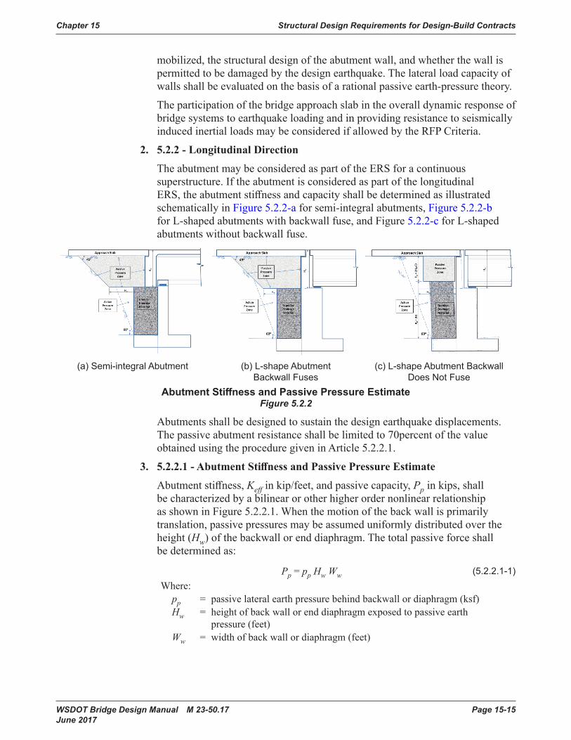
TheabutmentmaybeconsideredaspartoftheERSforacontinuoussuperstructure.IftheabutmentisconsideredaspartofthelongitudinalERS,theabutmentstiffnessandcapacityshallbedeterminedasillustratedschematicallyinFigure5.2.2-aforsemi-integralabutments,Figure5.2.2-b forL-shapedabutmentswithbackwallfuse,andFigure5.2.2-cforL-shapedabutmentswithoutbackwallfuse.
Longitudinalrestrainersshallnotbeusedattheendpiers(abutments).
4.2.11 Abutments
(a)Semi-integralAbutment (b)L-shapeAbutmentBackwallFuses
(c)L-shapeAbutmentBackwallDoesNotFuse
Figure5.2.2- AbutmentStiffnessandPassivePressure EstimateBDM Figure 4.2.11-1
Wherethepassivepressureresistanceofsoilsbehindsemi-integralorL-shapeabut-mentswillbemobilizedthroughlargelongitudinalsuperstructuredisplacements,thebridgemaybedesignedwiththeabutmentsaskeyelementsofthelongitudinalERS.Abutmentsshallbedesignedtosustainthedesignearthquakedisplacements.Whenabutmentstiffnessandcapacityareincludedinthedesign,itshouldberecognizedthatthepassivepressurezonemobilizedbyabutmentdisplacementextendsbeyondtheactivepressurezonenormallyusedforstaticserviceloaddesign.Thisisillustrat-edschematicallyinFigures1aand1b. Dynamicactiveearthpressureactingontheabutmentneednotbeconsideredinthedynamicanalysisofthebridge. Thepassiveabutmentresistanceshallbelimitedto70%ofthevalueobtainedusingtheproceduregiveninArticle5.2.2.1.
5.2.2.1 - AbutmentStiffnessandPassivePressureEstimate
Abutmentstiffness,Keff inkip/ft,andpassivecapacity,Pp inkips,shouldbecharac-terizedbyabilinearorotherhigherordernonlinearrelationshipasshowninFigure5.2.2.1.Whenthemotionofthebackwallisprimarilytranslation,passivepressuresmaybeassumeduniformlydistributedovertheheight(Hw)ofthebackwallorenddiaphragm.Thetotalpassiveforcemaybedeterminedas:
Pp = pp Hw Ww (5.2.2.1-1)
where:
(a) Semi-integral Abutment (b) L-shape Abutment Backwall Fuses
(c) L-shape Abutment Backwall Does Not Fuse
AbutmentStiffnessandPassivePressureEstimateFigure 5.2.2
Abutmentsshallbedesignedtosustainthedesignearthquakedisplacements.Thepassiveabutmentresistanceshallbelimitedto70percentofthevalueobtainedusingtheproceduregiveninArticle5.2.2.1.
3. 5.2.2.1-AbutmentStiffnessandPassivePressureEstimate
Abutmentstiffness,Keffinkip/feet,andpassivecapacity,Ppinkips,shallbecharacterizedbyabilinearorotherhigherordernonlinearrelationshipasshowninFigure5.2.2.1.Whenthemotionofthebackwallisprimarilytranslation,passivepressuresmaybeassumeduniformlydistributedovertheheight(Hw)ofthebackwallorenddiaphragm.Thetotalpassiveforceshallbedeterminedas:
Pp = pp Hw Ww (5 .2 .2 .1-1)Where:
pp = passivelateralearthpressurebehindbackwallordiaphragm(ksf)Hw = heightofbackwallorenddiaphragmexposedtopassiveearth
pressure(feet)Ww = widthofbackwallordiaphragm(feet)
Structural Design Requirements for Design-Build Contracts Chapter 15
Page 15-16 WSDOT Bridge Design Manual M 23-50.17 June 2017
Pp = pp Hw Ww (5.2.2.1-1)
where:
pp =passivelateralearthpressurebehindbackwallordiaphragm(ksf)
Hw =heightofbackwallorenddiaphragmexposedtopassiveearthpressure(ft)
Ww =widthofbackwallordiaphragm(ft)
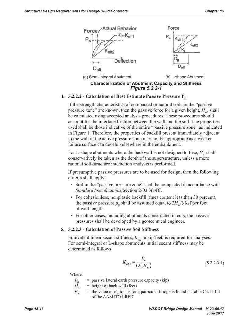
(a) Semi-integralAbutment (b): L-shapeAbutment
Figure5.2.2.1- CharacterizationofAbutmentCapacityandStiffnessBDM Figure 4.2.11-2
5.2.2.2- CalculationofBestEstimatePassivePressurePp
Ifthestrengthcharacteristicsofcompactedornaturalsoilsinthe"passivepressurezone"areknown,thenthepassiveforceforagivenheight,Hw, maybecalculatedus-ingacceptedanalysisprocedures.Theseproceduresshouldaccountfortheinterfacefrictionbetweenthewallandthesoil.Thepropertiesusedshallbethoseindicativeoftheentire"passivepressurezone"asindicatedinFigure1. Therefore,thepropertiesofbackfillpresentimmediatelyadjacenttothewallintheactivepressurezone maynotbeappropriateasaweakerfailuresurfacecandevelopelsewhereintheembank-ment.
ForL-shapeabutmentswherethebackwallisnotdesignedtofuse,Hw
shallconservativelybetakenasthedepthofthesuperstructure,unlessamorerationalsoil-structureinteractionanalysisisperformed.
Ifpresumptivepassivepressuresaretobeusedfordesign,thenthefollowingcriteriashallapply:
Pp = pp Hw Ww (5.2.2.1-1)
where:
pp =passivelateralearthpressurebehindbackwallordiaphragm(ksf)
Hw =heightofbackwallorenddiaphragmexposedtopassiveearthpressure(ft)
Ww =widthofbackwallordiaphragm(ft)
(a) Semi-integralAbutment (b): L-shapeAbutment
Figure5.2.2.1- CharacterizationofAbutmentCapacityandStiffnessBDM Figure 4.2.11-2
5.2.2.2- CalculationofBestEstimatePassivePressurePp
Ifthestrengthcharacteristicsofcompactedornaturalsoilsinthe"passivepressurezone"areknown,thenthepassiveforceforagivenheight,Hw, maybecalculatedus-ingacceptedanalysisprocedures.Theseproceduresshouldaccountfortheinterfacefrictionbetweenthewallandthesoil.Thepropertiesusedshallbethoseindicativeoftheentire"passivepressurezone"asindicatedinFigure1. Therefore,thepropertiesofbackfillpresentimmediatelyadjacenttothewallintheactivepressurezone maynotbeappropriateasaweakerfailuresurfacecandevelopelsewhereintheembank-ment.
ForL-shapeabutmentswherethebackwallisnotdesignedtofuse,Hw
shallconservativelybetakenasthedepthofthesuperstructure,unlessamorerationalsoil-structureinteractionanalysisisperformed.
Ifpresumptivepassivepressuresaretobeusedfordesign,thenthefollowingcriteriashallapply:
(a) Semi-integral Abutment (b) L-shape AbutmentCharacterizationofAbutmentCapacityandStiffness
Figure 5.2.2-14. 5.2.2.2-CalculationofBestEstimatePassivePressurePp Ifthestrengthcharacteristicsofcompactedornaturalsoilsinthe“passive
pressurezone”areknown,thenthepassiveforceforagivenheight,Hw,shallbecalculatedusingacceptedanalysisprocedures.Theseproceduresshouldaccountfortheinterfacefrictionbetweenthewallandthesoil.Thepropertiesusedshallbethoseindicativeoftheentire“passivepressurezone”asindicatedinFigure1.Therefore,thepropertiesofbackfillpresentimmediatelyadjacenttothewallintheactivepressurezonemaynotbeappropriateasaweakerfailuresurfacecandevelopelsewhereintheembankment.
ForL-shapeabutmentswherethebackwallisnotdesignedtofuse,Hwshallconservativelybetakenasthedepthofthesuperstructure,unlessamorerationalsoil-structureinteractionanalysisisperformed.
Ifpresumptivepassivepressuresaretobeusedfordesign,thenthefollowingcriteriashallapply:• Soilinthe“passivepressurezone”shallbecompactedinaccordancewith
Standard Specifications Section2-03.3(14)I.• Forcohesionless,nonplasticbackfill(finescontentlessthan30percent),thepassivepressureppshallbeassumedequalto2Hw/3ksfperfootofwalllength.
• Forothercases,includingabutmentsconstructedincuts,thepassivepressuresshallbedevelopedbyageotechnicalengineer.
5. 5.2.2.3-CalculationofPassiveSoilStiffness
Equivalentlinearsecantstiffness,Keffinkip/feet,isrequiredforanalyses.Forsemi-integralorL-shapeabutmentsinitialsecantstiffnessmaybedeterminedasfollows:
5.2.2.3- Calculation of Passive Soil Stiffness
Equivalentlinearsecantstiffness,Keff inkip/ft,isrequiredforanalyses.Forsemi-integralorL-shapeabutmentsinitialsecantstiffnessmaybedeterminedasfol-lows:
( )ww
peff HF
PK =1 (5.2.2.3-1)
where:
Pp =passivelateralearthpressurecapacity(kip)
Hw =heightofbackwall(ft)
Fw = thevalueofFw touseforaparticularbridgemaybefoundinTableC3.11.1-1oftheAASHTO LRFD Bridge Design Specifications.
ForL-shapeabutments,theexpansiongapshouldbeincludedintheinitialestimateofthesecantstiffnessasspecifiedin:
( )gww
peff DHF
PK
+=1 (5.2.2.3-2)
where:
Dg =widthofgapbetweenbackwallandsuperstructure(ft)
ForSDCsCandD,wherepushoveranalysesareconducted,valuesofPp andtheini-tialestimateofKeff1 shouldbeusedtodefineabilinearload-displacementbehavioroftheabutmentforthecapacityassessment.
5.2.2.4-Modeling Passive Pressure Stiffness in the Longitudinal Direction
Inthelongitudinaldirection,whenthebridgeismovingtowardthesoil, thefullpas-siveresistanceofthesoilmaybemobilized,butwhenthebridgemovesawayfromthesoilnosoilresistanceismobilized. Sincepassivepressureactsatonlyoneabutmentatatime,linearelasticdynamicmodelsandframepushovermodelsshouldonlyincludeapassivepressurespringatoneabutmentinanygivenmodel.Secantstiffnessvaluesforpassivepressureshallbedevelopedindependentlyforeachabut-ment.
(5 .2 .2 .3-1)
Where:Pp = passivelateralearthpressurecapacity(kip)Hw = heightofbackwall(feet)Fw = thevalueofFwtouseforaparticularbridgeisfoundinTableC3.11.1-1
oftheAASHTOLRFD.
Chapter 15 Structural Design Requirements for Design-Build Contracts
WSDOT Bridge Design Manual M 23-50.17 Page 15-17 June 2017
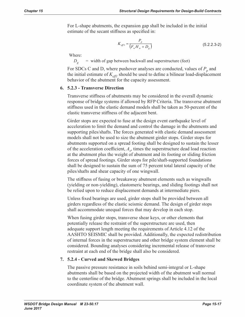
ForL-shapeabutments,theexpansiongapshallbeincludedintheinitialestimateofthesecantstiffnessasspecifiedin:
5.2.2.3- Calculation of Passive Soil Stiffness
Equivalentlinearsecantstiffness,Keff inkip/ft,isrequiredforanalyses.Forsemi-integralorL-shapeabutmentsinitialsecantstiffnessmaybedeterminedasfol-lows:
( )ww
peff HF
PK =1 (5.2.2.3-1)
where:
Pp =passivelateralearthpressurecapacity(kip)
Hw =heightofbackwall(ft)
Fw = thevalueofFw touseforaparticularbridgemaybefoundinTableC3.11.1-1oftheAASHTO LRFD Bridge Design Specifications.
ForL-shapeabutments,theexpansiongapshouldbeincludedintheinitialestimateofthesecantstiffnessasspecifiedin:
( )gww
peff DHF
PK
+=1 (5.2.2.3-2)
where:
Dg =widthofgapbetweenbackwallandsuperstructure(ft)
ForSDCsCandD,wherepushoveranalysesareconducted,valuesofPp andtheini-tialestimateofKeff1 shouldbeusedtodefineabilinearload-displacementbehavioroftheabutmentforthecapacityassessment.
5.2.2.4-Modeling Passive Pressure Stiffness in the Longitudinal Direction
Inthelongitudinaldirection,whenthebridgeismovingtowardthesoil, thefullpas-siveresistanceofthesoilmaybemobilized,butwhenthebridgemovesawayfromthesoilnosoilresistanceismobilized. Sincepassivepressureactsatonlyoneabutmentatatime,linearelasticdynamicmodelsandframepushovermodelsshouldonlyincludeapassivepressurespringatoneabutmentinanygivenmodel.Secantstiffnessvaluesforpassivepressureshallbedevelopedindependentlyforeachabut-ment.
(5 .2 .2 .3-2)
Where:Dg = widthofgapbetweenbackwallandsuperstructure(feet)
ForSDCsCandD,wherepushoveranalysesareconducted,valuesofPpandtheinitialestimateofKeff1shouldbeusedtodefineabilinearload-displacementbehavioroftheabutmentforthecapacityassessment.
6. 5.2.3-TransverseDirection
TransversestiffnessofabutmentsmaybeconsideredintheoveralldynamicresponseofbridgesystemsifallowedbyRFPCriteria.Thetransverseabutmentstiffnessusedintheelasticdemandmodelsshallbetakenas50-percentoftheelastictransversestiffnessoftheadjacentbent.
Girderstopsareexpectedtofuseatthedesigneventearthquakelevelofaccelerationtolimitthedemandandcontrolthedamageintheabutmentsandsupportingpiles/shafts.Theforcesgeneratedwithelasticdemandassessmentmodelsshallnotbeusedtosizetheabutmentgirderstops.Girderstopsforabutmentssupportedonaspreadfootingshallbedesignedtosustainthelesseroftheaccelerationcoefficient,As,timesthesuperstructuredeadloadreactionattheabutmentplustheweightofabutmentanditsfootingorslidingfrictionforcesofspreadfootings.Girderstopsforpile/shaft-supportedfoundationsshallbedesignedtosustainthesumof75percenttotallateralcapacityofthepiles/shaftsandshearcapacityofonewingwall.
Thestiffnessoffusingorbreakawayabutmentelementssuchaswingwalls(yieldingornon-yielding),elastomericbearings,andslidingfootingsshallnotbereliedupontoreducedisplacementdemandsatintermediatepiers.
Unlessfixedbearingsareused,girderstopsshallbeprovidedbetweenallgirdersregardlessoftheelasticseismicdemand.Thedesignofgirderstopsshallaccommodateunequalforcesthatmaydevelopineachstop.
Whenfusinggirderstops,transverseshearkeys,orotherelementsthatpotentiallyreleasetherestraintofthesuperstructureareused,thenadequatesupportlengthmeetingtherequirementsofArticle4.12oftheAASHTOSEISMICshallbeprovided.Additionally,theexpectedredistributionofinternalforcesinthesuperstructureandotherbridgesystemelementshallbeconsidered.Boundinganalysesconsideringincrementalreleaseoftransverserestraintateachendofthebridgeshallalsobeconsidered.
7. 5.2.4-CurvedandSkewedBridges
Thepassivepressureresistanceinsoilsbehindsemi-integralorL-shapeabutmentsshallbebasedontheprojectedwidthoftheabutmentwallnormaltothecenterlineofthebridge.Abutmentspringsshallbeincludedinthelocalcoordinatesystemoftheabutmentwall.
Structural Design Requirements for Design-Build Contracts Chapter 15
Page 15-18 WSDOT Bridge Design Manual M 23-50.17 June 2017
L. Foundation – General
GuideSpecificationsArticle5.3.1
TherequiredFoundationModelingMethod(FMM)andtherequirementsforestimationoffoundationspringsforspreadfootings,pilefoundations,anddrilledshaftsshallbeModelingMethodIIasdefinedinTable5.3.1-1.
M.Foundation–SpreadFooting
GuideSpecificationsArticleC5.3.2
FoundationspringsforspreadfootingsshallbedeterminedinaccordancewithSection7.2.7 andGeotechnical Design Manual Section6.5.1.1.
N. Procedure3:NonlinearTimeHistoryMethod
GuideSpecificationsArticle5.4.4
ThetimehistoriesofaccelerationusedtodescribetheearthquakeloadsshallbeselectedinaccordancewithGeotechnical Design ManualSection6-A.6.
O. IeffforBoxGirderSuperstructure
GuideSpecificationsArticle5.6.3
Thegrossmomentofinertiashallbeusedforboxgirdersuperstructuremodeling.
P. Foundation Rocking
GuideSpecificationsArticle6.3.9
FoundationrockingshallnotbeusedforthedesignofWSDOTbridges.
Q. Drilled Shafts
GuideSpecificationsArticleC6.5
ForWSDOTbridges,thescalefactorforp-ycurvesorsubgrademodulusforlargediametershaftsshallnotbeused.
R. LongitudinalDirectionRequirements
GuideSpecificationsArticle6.7.1
Case2:EarthquakeResistingSystem(ERS)withabutmentcontributionmaybeusedprovidedthatthemobilizedlongitudinalpassivepressureisnotgreaterthan70percentofthevalueobtainedusingtheproceduregiveninArticle5.2.2.1.
S. LiquefactionDesignRequirements
GuideSpecificationsArticle6.8
SoilliquefactionassessmentshallbebasedonGeotechnical Design Manual Section6.4.2.8.
T. Reinforcing Steel
GuideSpecificationsArticle8.4.1
Reinforcingbars,deformedwire,cold-drawwire,weldedplainwirefabricandweldeddeformedwirefabricshallconformtothematerialstandardsasspecifiedinAASHTOLRFD.
Chapter 15 Structural Design Requirements for Design-Build Contracts
WSDOT Bridge Design Manual M 23-50.17 Page 15-19 June 2017
SteelreinforcementshallconformtoStandard Specifications Section9-07.2andthefollowingcriteria.OnlyASTMA706Grade60reinforcingsteelshallbeusedinmemberswhereplastichingingisexpectedforSDCsB,C,andD.ASTMA706Grade80reinforcingsteelsmaybeusedforcapacity-protectedmembersasspecifiedinArticle8.9.ASTMA706Grade80reinforcingsteelshallnotbeusedforoversizedshaftswherein-groundplastichingingisconsideredasapartofERS.
Deformedweldedwirefabricshallnotbeused.
Wireropeorstrandsforspiralsandhighstrengthbarswithyieldstrengthinexcessof75ksishallnotbeused.
GuideSpecificationsArticleC8.4.1
TherequirementsforplastichingingandcapacityprotectedmembersdonotapplytothestructuresinSDCA,thereforeuseofASTMA706Grade80reinforcingsteelispermittedinSDCA.
ForSDCsB,C,andD,themoment-curvatureanalysesbasedonstraincompatibilityandnonlinearstress/strainrelationsareusedtodeterminetheplasticmomentcapacitiesofallductileconcretemembers.Furtherresearchisrequiredtoestablishtheshapeandmodelofthestress-straincurve,expectedreinforcingstrengths,strainlimits,andthestress-strainrelationshipsforconcreteconfinedbylateralreinforcementmadewithASTMA706Grade80reinforcingsteel.
U. Concrete Modeling
GuideSpecificationsArticle8.4.4
Wherein-groundplastichingingispartoftheERS,theconfinedconcretecoreshallbelimitedtoamaximumcompressivestrainof0.008andthememberductilitydemandshallbelimitedto4maximum.
V. ExpectedNominalMomentCapacity
GuideSpecificationsArticle8.5
TheexpectednominalcapacityofcapacityprotectedmembersusingASTMA706Grade80reinforcementshallbedeterminedbystrengthdesignformulasspecifiedintheAASHTOLRFDbasedontheexpectedconcretestrengthandreinforcingsteelyieldstrengthswhentheconcretereaches0.003orthereinforcingsteelstrainreaches0.090for#10barsandsmaller,0.060for#11barsandlarger.
Replacethedefinitionofλmowiththefollowing:
λmo=overstrengthfactor
=1.2forASTMA706Grade60reinforcement
=1.4forASTMA615Grade60reinforcement
W. Interlocking Bar Size
GuideSpecificationsArticle8.6.7
Thelongitudinalreinforcingbarinsidetheinterlockingportionofacolumn(interlockingbars)shallbethesamesizeofbarsusedoutsidetheinterlockingportion.
Structural Design Requirements for Design-Build Contracts Chapter 15
Page 15-20 WSDOT Bridge Design Manual M 23-50.17 June 2017
X. SplicingofLongitudinalReinforcementinColumnsSubjecttoDuctilityDemandsforSDCsCandD
GuideSpecificationsArticle8.8.3
Thesplicingoflongitudinalcolumnreinforcementoutsidetheplastichingingregionshallbeaccomplishedusingmechanicalcouplersthatarecapableofdevelopingthetensilestrengthofthesplicedbar.Splicesshallbestaggeredatleast2feet.Lapsplicesshallnotbeused.Thedesignengineershallclearlyidentifythelocationswheresplicesinlongitudinalcolumnreinforcementarepermittedontheplans.Ingeneralwherethelengthoftherebarcageislessthan60feet(72feetforNo.14andNo.18bars),nospliceinthelongitudinalreinforcementshallbeallowed.
Y. DevelopmentLengthforColumnBarsExtendedintoOversizedPileShaftsfor SDCs C and D
GuideSpecificationsArticle8.8.10
ExtendingcolumnbarsintooversizedshaftshallbeinaccordancewithSection7.4.4.C,basedonTRACReportWARD417.1“Non-Contact Lap Splice in Bridge Column Shaft Connections”.
Z. LateralConfinementforOversizedPileShaftforSDCsCandD
GuideSpecificationsArticle8.8.12
Therequirementofthisarticleforshaftlateralreinforcementinthecolumn-shaftsplicezonemaybereplacedwiththerequirementsofSection7.8.2.K.
AA.LateralConfinementforNon-OversizedStrengthenedPileShaftforSDCsC and D
GuideSpecificationsArticle8.8.13
Non-oversizedcolumn-shaft(thecrosssectionoftheconfinedcoreisthesameforboththecolumnandthepileshaft)isnotpermissibleunlessallowedbytheRFPCriteria.
AB. RequirementsforCapacityProtectedMembers
GuideSpecificationsArticle8.9
ForSDCsCandDwhereliquefactionisidentified,pileanddrilledshaftingroundhingingmaybeconsideredasanERE.
Bridgesshallbeanalyzedanddesignedforthenon-liquefiedconditionandtheliquefiedconditioninaccordancewithArticle6.8.ThecapacityprotectedmembersshallbedesignedinaccordancewiththerequirementsofArticle4.11.Toensuretheformationofplastichingesincolumns,oversizedpileshaftsshallbedesignedforanexpectednominalmomentcapacity,Mne,atanylocationalongtheshaft,thatis,equalto1.25timesmomentdemandgeneratedbytheoverstrengthcolumnplastichingemomentandassociatedshearforceatthebaseofthecolumn.Thesafetyfactorof1.25maybereducedto1.0dependingonthesoilproperties.
Chapter 15 Structural Design Requirements for Design-Build Contracts
WSDOT Bridge Design Manual M 23-50.17 Page 15-21 June 2017
Thedesignmomentsbelowgroundforextendedpileshaftmaybedeterminedusingthenonlinearstaticprocedure(pushoveranalysis)bypushingthemlaterallytothedisplacementdemandobtainedfromanelasticresponsespectrumanalysis.Thepointofmaximummomentshallbeidentifiedbasedonthemomentdiagram.Theexpectedplastichingezoneshallextend3Daboveandbelowthepointofmaximummoment.Theplastichingezoneshallbedesignatedasa“nosplice”zoneandthetransversesteelforshearandconfinementshallbeprovidedaccordingly.
AC. SuperstructureCapacityDesignforTransverseDirection(IntegralBentCap)forSDCsCandD
GuideSpecificationsArticle8.11
ForSDCsCandD,thelongitudinalflexuralbentcapbeamreinforcementshallbecontinuous.Splicingofcapbeamlongitudinalflexuralreinforcementshallbeaccomplishedusingmechanicalcouplersthatarecapableofdevelopingthetensilestrengthofthesplicedbar.Splicesshallbestaggeredatleast2feet.Lapsplicesshallnotbeused.
AD. SuperstructureDesignforNonIntegralBentCapsforSDCsB,C,andD
GuideSpecificationsArticle8.12
NonintegralbentcapsshallnotbeusedforcontinuousconcretebridgesinSDCB,C,andDexceptattheexpansionjointsbetweensuperstructuresegments.
AE. IntegralBentCapJointShearDesign
GuideSpecificationsArticle8.13.4.1.1
InadditiontotheT-jointslistedinArticle8.13.4.1.1,theexteriorcolumnjointsforboxgirdersuperstructureandothersuperstructuresifthecapbeamextendsthejointfarenoughtodevelopthelongitudinalcapreinforcementshallbeconsideredT-jointsforjointshearanalysisinthetransversedirection.
AF. CastinPlace and Precast Concrete Piles
GuideSpecificationsArticle8.16.2
Minimumlongitudinalreinforcementof0.75percentofAgshallbeprovidedforCIPpilesinSDCsB,C,andD.Longitudinalreinforcementshallbeprovidedforthefulllengthofpile.
15.4.3 SeismicDesignRequirementsforBridgeModificationsandWidening Projects
A. SeismicAnalysisandRetrofitPolicy
TheSeismicAnalysisandRetrofitPolicyforBridgeModificationsandWideningProjectsshallconformtoSections 4.3.1 ,4.3.2,4.3.3,and4.3.4.
ThespectralresponseparametersshallbedeterminedusingUSGS2014SeismicHazardMapsandSiteCoefficientsdefinedinSection4.2.3.
Structural Design Requirements for Design-Build Contracts Chapter 15
Page 15-22 WSDOT Bridge Design Manual M 23-50.17 June 2017
B. Design and Detailing Considerations
1. SupportLength
Thesupportlengthatexistingabutments,piers,inspanhinges,andpavementseatsshallbechecked.Ifthereisaneedforlongitudinalrestrainers,transverserestrainers,oradditionalsupportlengthontheexistingstructure,theyshallbeincludedinthewideningdesign.
2. ConnectionsBetweenExistingandNewElements
Connectionsbetweentheexistingelementsandnewelementsshallbedesignedformaximumoverstrengthforces.Whereyieldingisexpectedinthecrossbeamconnectionattheextremeeventlimitstate,thenewstructureshallbedesignedtocarryliveloadsindependentlyattheStrengthIlimitstate.Incaseswherelargedifferentialsettlementand/oraliquefactioninducedlossofbearingstrengthareexpected,theconnectionsmaybedesignedtodeflectorhingeinordertoisolatethetwopartsofthestructure.Elementssubjecttoinelasticbehaviorshallbedesignedanddetailedtosustaintheexpecteddeformations.
Longitudinaljointsthatisolatethedecksbetweentheexistingandnewstructuresarenotpermitted.
3. DifferentialSettlement
Thedesignershallevaluatethepotentialfordifferentialsettlementbetweentheexistingstructureandwideningstructure.Additionalgeotechnicalmeasuresmayberequiredtolimitdifferentialsettlementstotolerablelevelsforbothstaticandseismicconditions.Thebridgedesignershallevaluate,design,anddetailallelementsofnewandexistingportionsofthewidenedstructureforthedifferentialsettlementwarrantedbythegeotechnicalengineer.Angulardistortionsbetweenadjacentfoundationsshallnotexceed0.008(RAD)insimplespansand0.004(RAD)incontinuousspans.
Thehorizontaldisplacementofpileandshaftfoundationsshallbeestimatedusingproceduresthatconsidersoilstructureinteraction(seeGeotechnical Design ManualSection8.12.2.3).Horizontalmovementcriteriashallbeestablishedatthetopofthefoundationbasedonthetoleranceofthestructuretolateralmovementwithconsiderationofthecolumnlengthandstiffness.Toleranceofthesuperstructuretolateralmovementwilldependonbridgeseatwidths,bearingtype(s),structuretype,andloaddistributioneffects.
4. FoundationTypes
Thefoundationtypeofthenewstructureshouldmatchthatoftheexistingstructure.However,adifferenttypeoffoundationmaybeusedforthenewstructureduetogeotechnicalrecommendationsorthelimitedspaceavailablebetweenexistingandnewstructures.Forexample,ashaftfoundationmaybeusedinlieuofspreadfooting.
5. ExistingStruttedColumns
Thehorizontalstrutbetweenexistingcolumnsmayberemoved.Theexistingcolumnsshallthenbeanalyzedwiththenewunbracedlengthsandretrofittedifnecessary.
Chapter 15 Structural Design Requirements for Design-Build Contracts
WSDOT Bridge Design Manual M 23-50.17 Page 15-23 June 2017
6. NonStructuralElementStiffness
Medianbarriersandotherpotentiallystiffeningelementsshallbeisolatedfromthecolumnstoallowcolumndeformation.
DeformationcapacitiesofexistingbridgemembersthatdonotmeetcurrentdetailingstandardsshallbedeterminedusingtheprovisionsofSection7.8oftheRetrofitting Manual for Highway Structures: Part 1 – Bridges,FHWAHRT06032.DeformationcapacitiesofexistingbridgemembersthatmeetcurrentdetailingstandardsshallbedeterminedusingthelatesteditionoftheAASHTOSEISMIC.
Inlieuofspecificdata,thereinforcementpropertiesprovidedinTable4.3.2-1 shallbeused.
7. Isolation Bearings
Isolationbearingsmaybeusedforbridgewideningprojectstoreducetheseismicdemandthroughmodificationofthedynamicpropertiesofthebridge.IsolationbearingsshallbedesignedinaccordancewithAASHTOGuide Specifications for Seismic IsolationandshallconformtoSection9.3.
15.4.4 SeismicRetrofittingofExistingBridgesSeismicretrofittingofexistingbridgesshallbeperformedinaccordancewiththeFHWApublicationFHWAHRT06032,Seismic Retrofitting Manual for Highway Structures: Part 1 – Bridgesasfollows:• Article1.5.3ThespectralresponseparametersshallbedeterminedusingUSGS2014SeismicHazardMapsandSiteCoefficientsdefinedinSection4.2.3.
• Article7.4.2SeismicLoadinginTwoorThreeOrthogonal Revisethefirstparagraphasfollows: Whencombiningtheresponseoftwoorthreeorthogonaldirectionsthedesignvalueofanyquantityofinterest(displacement,bendingmoment,shearoraxialforce)shallbeobtainedbythe100-30percentcombinationruleasdescribedinAASHTOGuide SpecificationsArticle4.4.
• DeleteEq.7.44andreplacewiththefollowing:Lp=themaximumof[(8800εydb)or(0.08L+4400εydb)] (7-44)
• DeleteEq.7.49andreplacewiththefollowing:
Thehorizontalstrutbetweenexistingcolumnsmayberemoved.Theexistingcolumnsshallthenbeanalyzedwiththenewunbracedlengthsandretrofittedifnecessary.
6. NonStructuralElementStiffnessMedianbarriersandotherpotentiallystiffeningelementsshallbeisolatedfromthecolumnstoallowcolumndeformation.DeformationcapacitiesofexistingbridgemembersthatdonotmeetcurrentdetailingstandardsshallbedeterminedusingtheprovisionsofSection7.8oftheRetrofitting Manual for Highway Structures: Part 1 – Bridges,FHWA-HRT-06-032. DeformationcapacitiesofexistingbridgemembersthatmeetcurrentdetailingstandardsshallbedeterminedusingthelatesteditionoftheAASHTO Guide Specifications for LRFD Seismic Bridge Design.Inlieuofspecificdata,thereinforcementpropertiesprovidedinTable4.3.2-1shallbeused.
7. Isolation BearingsIsolationbearingsmaybeusedforbridgewideningprojectstoreducetheseismicdemandthroughmodificationofthedynamicpropertiesofthebridge.IsolationbearingsshallbedesignedinaccordancewithAASHTOGuide Specifications for Seismic Isolation andshallconformtoSection4.2.2.
15.4.4 Seismic Retrofitting of Existing BridgesSeismicretrofittingofexistingbridgesshallbeperformedinaccordancewiththeFHWApublicationFHWA-HRT-06-032, Seismic Retrofitting Manual for Highway Structures: Part 1 –Bridges asfollows:
• Article7.4.2SeismicLoadinginTwoorThreeOrthogonalDirectionsRevisethefirstparagraphasfollows:Whencombiningtheresponseoftwoorthreeorthogonaldirectionsthedesignvalueofanyquantityofinterest(displacement,bendingmoment,shearoraxialforce)shallbeobtainedbythe100-30percentcombinationruleasdescribedinAASHTO Guide SpecificationsArticle 4.4.
• DeleteEq.7.49andreplacewiththefollowing:
• DeleteEq.7.51andreplacewiththefollowing:
yfi
mip VV
VVφφ
+
−−
= 25
yjfji
jhjip VV
VVφφ
+
−
−= 24
• DeleteEq.7.51andreplacewiththefollowing:
Thehorizontalstrutbetweenexistingcolumnsmayberemoved.Theexistingcolumnsshallthenbeanalyzedwiththenewunbracedlengthsandretrofittedifnecessary.
6. NonStructuralElementStiffnessMedianbarriersandotherpotentiallystiffeningelementsshallbeisolatedfromthecolumnstoallowcolumndeformation.DeformationcapacitiesofexistingbridgemembersthatdonotmeetcurrentdetailingstandardsshallbedeterminedusingtheprovisionsofSection7.8oftheRetrofitting Manual for Highway Structures: Part 1 – Bridges,FHWA-HRT-06-032. DeformationcapacitiesofexistingbridgemembersthatmeetcurrentdetailingstandardsshallbedeterminedusingthelatesteditionoftheAASHTO Guide Specifications for LRFD Seismic Bridge Design.Inlieuofspecificdata,thereinforcementpropertiesprovidedinTable4.3.2-1shallbeused.
7. Isolation BearingsIsolationbearingsmaybeusedforbridgewideningprojectstoreducetheseismicdemandthroughmodificationofthedynamicpropertiesofthebridge.IsolationbearingsshallbedesignedinaccordancewithAASHTOGuide Specifications for Seismic Isolation andshallconformtoSection4.2.2.
15.4.4 Seismic Retrofitting of Existing BridgesSeismicretrofittingofexistingbridgesshallbeperformedinaccordancewiththeFHWApublicationFHWA-HRT-06-032, Seismic Retrofitting Manual for Highway Structures: Part 1 –Bridges asfollows:
• Article7.4.2SeismicLoadinginTwoorThreeOrthogonalDirectionsRevisethefirstparagraphasfollows:Whencombiningtheresponseoftwoorthreeorthogonaldirectionsthedesignvalueofanyquantityofinterest(displacement,bendingmoment,shearoraxialforce)shallbeobtainedbythe100-30percentcombinationruleasdescribedinAASHTO Guide SpecificationsArticle 4.4.
• DeleteEq.7.49andreplacewiththefollowing:
• DeleteEq.7.51andreplacewiththefollowing:
yfi
mip VV
VVφφ
+
−−
= 25
yjfji
jhjip VV
VVφφ
+
−
−= 24
Structural Design Requirements for Design-Build Contracts Chapter 15
Page 15-24 WSDOT Bridge Design Manual M 23-50.17 June 2017
A. SeismicAnalysisRequirements
Themulti-modespectralanalysisofSeismic Retrofitting ManualSection5.4.2.2(asaminimum)shallbeusedtodeterminetheseismicdisplacementandforcedemandstoidentifyseismicallydeficientelementsoftheexistingstructure.Prescriptiverequirements,suchassupportlength,shallbeconsideredmandatoryandshallbeincludedintheanalysis.SeismiccapacitiesshallbedeterminedinaccordancewiththerequirementsoftheSeismic Retrofitting Manual.DisplacementcapacitiesshallbedeterminedbytheMethodD2–StructureCapacity/Demand(Pushover)MethodofSeismic Retrofitting ManualSection5.6.Theseismicanalysisneedonlybeperformedfortheupperlevel(1,000yearreturnperiod)groundmotionswithalifesafetyseismicperformancelevel.
B. SeismicRetrofitDesign
Table111,Chapters8,9,10,11,andAppendicesDthruFoftheSeismic Retrofitting Manualshallbeusedinselectinganddesigningtheseismicretrofitmeasures.
C. Earthquake Restrainers
LongitudinalrestrainersshallbehighstrengthsteelrodsconformtoASTMF1554Grade105,includingSupplementRequirementsS2,S3andS5.Nuts,andcouplersifrequired,shallconformtoASTMA563GradeDH.WashersshallconformtoAASHTOM293.Highstrengthsteelrodsandassociatedcouplers,nutsandwashersshallbegalvanizedafterfabricationinaccordancewithAASHTOM232.Thelengthoflongitudinalrestrainersshallbelessthan24feet.
D. Isolation Bearings
Isolationbearingsmaybeusedforseismicretrofitprojectstoreducethedemandsthroughmodificationofthedynamicpropertiesofthebridgeasaviablealternativetostrengtheningweakelementsofnon-ductilebridgesubstructuremembersofexistingbridge.IsolationbearingsshallbedesignedinaccordancewiththerequirementoftheAASHTO Guide Specifications for Seismic IsolationandshallconformtoSection9.3.
WSDOT Bridge Design Manual M 23-50.17 Page 15-25 June 2017
15.5 Concrete Structures15.5.1 General
Designofconcretestructuresforroadwayelementssuchasbridges,lids,retainingwalls,noisewalls,three-sidedstructures,trafficbarrier,pedestrianbarrier,signstructures,bridgeapproachslabs,etc.shallbebasedontherequirementscitedhereinandinthecurrentAASHTOLRFD,AASHTOSEISMIC,WSDOTSpecialProvisionsandtheWSDOTStandard Specifications.
15.5.2 MaterialsA. Concrete
1. Cast-in-place(CIP)Concrete
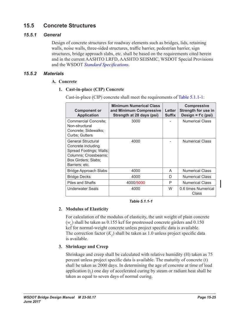
Cast-in-place(CIP)concreteshallmeettherequirementsofTable5.1.1-1:
Component or Application
Minimum Numerical Class andMinimumCompressive
Strength at 28 days (psi)Letter Suffix
CompressiveStrength for use in Design = f’c (psi)
Commercial Concrete; Non-structural Concrete; Sidewalks; Curbs; Gutters
3000 - Numerical Class
General Structural Concrete including Spread Footings; Walls; Columns; Crossbeams; Box Girders; Slabs; Barriers; etc .
4000 - Numerical Class
Bridge Approach Slabs 4000 A Numerical ClassBridge Decks 4000 D Numerical ClassPiles and Shafts 4000/5000 P Numerical ClassUnderwater Seals 4000 W 0 .6 times Numerical
Class
Table 5.1.1-1
2. Modulus of Elasticity
Forcalculationofthemodulusofelasticity,theunitweightofplainconcrete(wc)shallbetakenas0.155kcfforprestressedconcretegirdersand0.150kcffornormal-weightconcreteunlessprojectspecificdataisavailable.Thecorrectionfactor(K1)shallbetakenas1.0unlessprojectspecificdataisavailable.
3. ShrinkageandCreep
Shrinkageandcreepshallbecalculatedwithrelativehumidity(H)takenas75percentunlessprojectspecificdataisavailable.Thematurityofconcrete(t)shallbetakenas2000days.Indeterminingtheageofconcreteattimeofloadapplication(ti)onedayofacceleratedcuringbysteamorradiantheatshallbetakenasequaltosevendaysofnormalcuring.
Structural Design Requirements for Design-Build Contracts Chapter 15
Page 15-26 WSDOT Bridge Design Manual M 23-50.17 June 2017
4. Grout
Groutpadswiththicknessexceeding4″shallbereinforcedwithsteelreinforcement.Non-shrinkgroutconformingtoStandard Specifications Section9-20.3(2)shallbeusedinkeywaysbetweenprestressedconcretegirders.
5. Mass Concrete
Concreteplacementswithaleastdimensionofgreaterthan6-feetshallbeconsideredmassconcrete,exceptthatshaftsneednotbeconsideredmassconcrete.
Thetemperatureofmassconcreteduringplacementandcuringshallnotexceed160°F.Thetemperaturedifferencebetweenthegeometriccenterofthemassconcreteandthecenterofnearbyexteriorsurfacesduringplacementandcuringshallnotexceed35°F.
AthermalcontrolplanshallbesubmittedbytheDesign-Builderforreviewandcommentformassconcreteplacements.Thethermalcontrolplanmayincludesuchthingsas:athermalanalysis;temperaturemonitorsandequipment;insulation;concretecoolingbeforeplacement;concretecoolingafterplacement,suchasbymeansofinternalcoolingpipes;useofsmaller,lessfrequentplacements;orothermethodsproposedbytheDesign-BuilderandacceptedbytheWSDOTEngineer.
Concretemixdesignsmaybeoptimized(suchasbyusinglow-heatcement,flyashorslagcement,low-water/cementratio,lowcementitiousmaterialscontent,largeraggregate,etc.)aslongastheconcretemixmeetsotherprojectrequirements.
6. Shotcrete
Shotcreteshallnotbeusedforpermanentstructures,includingexteriorwallfasciasurfaces,unlessallowedbyRFPCriteria.Shotcretemaybeusedfortemporaryapplications.
7. Lightweight Aggregate Concrete
Lightweightaggregateconcreteshallnotbeused,unlessallowedbyRFPCriteria.
B. Reinforcing Steel
1. Grades
SteelreinforcingbarsshallconformtoStandard Specifications Section9-07.2andSection15.4.2.T.UseofASTMA706Grade80steelreinforcingbarsshallconformtoSection5.1.2
2. CompressiveDevelopmentLength
Theminimumcompressivedevelopmentlengthshallbe1′-0″.
3. Splices
Minimumlapsplicelengths,forbothtensionandcompression,shallbe2′-0″.Whentwobarsofdifferentdiametersarelapspliced,thelengthofthelapspliceshallbethelargerofthelapspliceforthesmallerbarorthedevelopmentlengthforthelargerbar.
Chapter 15 Structural Design Requirements for Design-Build Contracts
WSDOT Bridge Design Manual M 23-50.17 Page 15-27 June 2017
4. WeldedWireReinforcementinPrestressedConcreteGirders,Walls,Barriers and Deck Panels
Weldedwirereinforcementmaybeusedtoreplacesteelreinforcingbarsinprestressedconcretegirders,walls,barriers,anddeckpanels.
Weldedwirereinforcementshallbedeformed.
Longitudinalwiresandweldsshallbeexcludedfromregionswithhighsheardemands,includinggirderwebs.Longitudinalwiresforanchorageofweldedwirereinforcementshallhaveanareaof40percentormoreoftheareaofthewirebeinganchoredasdescribedinASTMA497butshallnotbelessthanD4.
5. Reinforcing Bar Dowels and Resin Bonded Anchors
AllowabletensileloadsandminimumrequiredembedmentforreinforcingbardowelsshallbeinaccordancewithSection5.5.4.A.4.Ifitisnotpossibletoobtainthisembedment,theallowableloadonthedowelshallbereducedbytheratiooftheactualembedmentdividedbytherequiredembedment.
Beforecoredrilling,existingreinforcementshallbelocatedbynon-destructivemethodsorbychippingifexistingreinforcementcannotbedamaged.Coredrilledholesshallberoughened.
C. Prestressing Steel
PrestressingsteelshallbeAASHTOM203Grade270lowrelaxationforstrandsandAASHTOM275TypeIIforbars.
Therefinedestimateforcomputingtime-dependentlossesshallbeused.
Partialprestressingisnotpermitted.
15.5.3 Design ConsiderationsA. ServiceandFatigueLimitStates
TheexposurefactorforAASHTOLRFDSection 5.6.7“ControlofCrackingbyDistributionofReinforcement”shallbebaseduponaClass2exposurecondition.
ConcretestressesinprestressedmembersshallbelimitedtotheallowablestressesshowninTable5.2.1-1.
B. StrengthLimitState
ThesheardesignofprestressedmembersshallbebasedonthegeneralprocedureofAASHTOLRFDSection5.7.3.4.2.Thesheardesignofnon-prestressedmembersshallbebasedoneitherthegeneralprocedure,orthesimplifiedprocedureofAASHTOLRFDSection5.7.3.4.1.AASHTOLRFDSection5.8.3.4.3“SimplifiedProcedureforPrestressedandNon-prestressedSections”shallnotbeused.
Themaximumspacingofshearandtorsionreinforcementshallbe18inches.
C. Post-Tensioning
A2″minimumclearanceshallbeprovidedbetweenpost-tensioningductswithouterdiametergreaterthan3″.A1″minimumclearanceshallbeprovidedbetweenpost-tensioningductswithouterdiameterlessthanorequalto3″.
Structural Design Requirements for Design-Build Contracts Chapter 15
Page 15-28 WSDOT Bridge Design Manual M 23-50.17 June 2017
Confinementreinforcementshallbeprovidedtoconfinecurvedpost-tensioningtendonsinaccordancewithSection5.8.1.F.
Thesizeoftheanchoragezoneintheplaneofanchorplatesshallbelargeenoughtoprovideaminimumof1″clearancefromtheplatestoanyfreeedge.
Structureshorteningeffectsduetopost-tensioningshallbeincludedinthedesign.
Thecambershallbeshownontheplansandshallincludetheeffectofbothdeadloadandfinalprestressing.
Allpost-tensioninganchoragesinwebsofboxgirderormulti-stemsuperstructureshallbeverticallyaligned.Tendonsadjacenttopost-tensioninganchoragesshallmeettheminimumtangentlengthandminimumtendonradiirequirementsofSection5.8.1.D.
15.5.4 SuperstructuresA. ReinforcedConcreteSuperstructures
TheuseofCIPreinforcedconcretebridgesuperstructureswithoutpost-tensioningshallberestrictedtowideningexistingreinforcedconcretebridgesuperstructures.Longitudinalpost-tensioningshallbeprovidedforallnewCIPreinforcedconcretebridgesuperstructures.
B. BoxGirderSuperstructures
1. IntermediateDiaphragmsforCurvedConcreteBoxGirderBridges
Intermediatediaphragmsshallbeprovidedforcurvedconcreteboxgirderbridgeswithcenterlineradius,R,lessthan800feet.Minimumdiaphragmspacingshallbeasfollows:
For600feet≤R<800feet-atmidspan.
For400feet≤R<600feet-at⅓pointsofspan.
ForR<400feet-at¼pointsofspan.
2. TemperatureEffects
Thermalstressesshallbeinvestigatedindesignusingthefollowingcriteria:
a. Ameantemperature50°Fwithrise45°Fandfall45°Fforlongitudinalanalysisusingone-halfofthemodulusofelasticity(MaximumSeasonalVariation.)
b. Thesuperstructureboxgirdershallbedesignedtransverselyforatemperaturedifferentialbetweeninsideandoutsidesurfacesof±15°Fwithnoreductioninmodulusofelasticity(MaximumDailyVariation).
c. Thesuperstructureboxgirdershallbedesignedlongitudinallyforatopslabtemperatureincreaseof20°Fwithnoreductioninmodulusofelasticity.
Chapter 15 Structural Design Requirements for Design-Build Contracts
WSDOT Bridge Design Manual M 23-50.17 Page 15-29 June 2017
3. Drains
Drainsshallbeplacedinthebottomslabatthelowpointsofeachcell.DrainholedetailsshallbeinaccordancewithFigure5.3.8-1.
C. PrestressedConcreteGirderSuperstructures
1. WSDOTStandardGirderTypesandConstructionSequences
PrestressedconcretegirdersshallbeaWSDOTstandardgirdertypeinaccordancewithAppendices5.6-A1-1and5.6-A1-9.
PrestressedconcretegirdersuperstructuresshallfollowaconstructionsequenceinaccordancewithAppendix5.6-A1-2.
2. SuperstructureContinuity
Prestressedconcretegirdersuperstructuresshallbedesignedfortheenvelopeofsimplespanandcontinuousspanloadingsforallpermanentandtransientloads.Loadsappliedbeforeestablishingcontinuity(typicallybeforeplacementofcontinuitydiaphragms)needonlybeappliedasasimplespanloading.Continuityreinforcementshallbeprovidedatsupportsforloadsappliedafterestablishingcontinuity.
3. ContinuousStructureConfiguration
Girdertypesandspacingshallbeidenticalinadjacentspansoverintermediatepiers.Girdertypesandspacingmaybechangedatexpansionjoints.
4. Girder Ends
PrestressedconcretegirdersshallhaveastandardendtypeinaccordancewithSection5.6.2.E.PrestressingstrandsatgirderendsshallbeextendedintodiaphragmsandmadecontinuousinaccordancewithSection5.1.3.D.
Girderendskewanglesfortrapezoidaltub,slab,wideflangedeck,wideflangethindeckanddeckbulb-teeprestressedconcretegirdersshallbelimitedto30degrees.Girderendskewanglesforallotherprestressedconcretegirdersshallbelimitedto45degrees.
Thesplittingresistanceofpre-tensionedanchoragezonesshallbeasdescribedinAASHTOLRFDSection5.9.4.4.1.Theendverticalreinforcementshallnotbelargerthan#5barsandspacingshallnotbelessthan2½″.Theremainingsplittingreinforcementnotfittingwithintheh/4zonemaybeplacedbeyondtheh/4zoneataspacingof2½″.
5. Diaphragms
Diaphragmsforprestressedconcretegirdersuperstructuresshallbecast-in-placeconcrete.
Diaphragmsshallbeorientedparalleltogirdersupportskew.Oncurvedbridges,diaphragmsshallbeplacedonradiallines.IntermediateandenddiaphragmsshallbeinaccordancewithAppendices5.6-A1-1and5.6-A1-9.
Structural Design Requirements for Design-Build Contracts Chapter 15
Page 15-30 WSDOT Bridge Design Manual M 23-50.17 June 2017
Intermediatediaphragmsshallbeprovidedforallprestressedconcretegirderbridges(exceptslabs)atthefollowinglocations:• 1/5pointsofspanforspanlength>160′-0″.• ¼pointsofspanfor120′-0″<spanlength≤160′-0″.• ⅓pointsofspanfor80′-0″<spanlength≤120′-0″.• Midpointofspanfor40′-0″<spanlength≤80′-0″.• Nodiaphragmrequirementforspanlength≤40′-0″.
Intermediatediaphragmsshallbefulldepthforstructurescrossingoverroadswithaveragedailytraffic(ADT)greaterthan50,000,inaccordancewithSection5.6.4.C.4.
6. Barrier and Sidewalk Load Distribution
Thedeadloadofonetrafficbarrierorsidewalkshallnotbedistributedovermorethanthreegirderwebs.
7. CompositeAction
CompositesectionpropertiesincludingeffectiveflangewidthofthecompositedeckshallbeinaccordancewithSection5.6.2.B.
8. Dead Loads
Thebridgedeckdeadloadtobeappliedtoagirdershallbebasedonthefullbridgedeckthickness.Thepad/haunchweightduetothemaximumpad/haunchheightshallbeaddedtothatloadoverthefulllengthofthegirder.
Whenthedepthofthepad/haunchbetweenthetopoftheprestressedconcretegirderandtheundersideofthedeckatthecenterlineofthegirderexceeds6″,reinforcementshallbeprovidedinthepadinaccordancewithFigure5.6.4-2.
9. GirderStirrups
Girderstirrupsshallbefieldbentoverthetopmatofreinforcementinthebridgedeckunlesspre-benthooksareallowedbytheWSDOTstandardgirdertypeorthepre-benthooksarewithinthecoreoftheCIPdeck(theinsideedgeofthehookterminatesabovethebottommatofthedeckbars).
10.TransformedSectionProperties
Transformedsectionpropertiesshallnotbeusedfordesignofprestressedconcretegirders.Grosssectionpropertiesshallbeused.
11. Deck Shrinkage
TheelasticgaininprestressingstrandsduetoslabshrinkageshallbecomputedinaccordancewithAASHTOLRFDSection5.9.3.4.3.d.DeckshrinkageshallbeconsideredasanexternalforceappliedtothecompositesectionfortheServiceI,ServiceIII,andFatigueIlimitstates.Thedeckshrinkagestrainshallbecomputedas50-percentofthestraindeterminedbyAASHTOLRFDEquation5.4.2.3.3-1.
Chapter 15 Structural Design Requirements for Design-Build Contracts
WSDOT Bridge Design Manual M 23-50.17 Page 15-31 June 2017
12. DeckGirderSuperstructures
Theterm“deckgirder”referstoaprestressedconcretegirderwhosetopflangeorsurfaceisthedrivingsurface,withorwithoutanoverlay,includingslabanddeckbulb-teegirders.
DeckgirderswithoutacompositeCIPdeckslabshallhaveaminimumconcretecoverof2″overthetopmat.Thetopmatofreinforcementinthetopflangeshallbeepoxy-coated.
13. Slab Girders
Slabgirderspansbetweencenterlinebearingsshallbelimitedtotheprestressedconcretegirderheightmultipliedby30.Aminimum5″compositeCIPbridgedeckshallbeplacedoverslabgirdersdirectlysupportingtrafficloadings.TheCIPconcretebridgedeckshallataminimumbeClass4000Dconcretewithonelayerof#5epoxycoatedreinforcementinboththetransverseandlongitudinaldirections.Thelongitudinalreinforcementshallbespacedat12inchesmaximumandthetransversereinforcementshallbespacedat6inchesmaximum.
14. Deck Bulb-Tee Girders
Deckbulb-teegirdersshallbelimitedtopedestrianbridges,temporarybridgesandtowideningexistingsimilarstructures.
Deckbulb-teegirdersshallhaveanHMAorconcreteoverlay.AwaterproofingmembraneshallbeprovidedwithanHMAoverlay.
15.WideFlangeDeckGirders
Wideflangedeckgirdersshallbelimitedtopedestrianbridges,temporarybridgesandtowideningexistingsimilarstructures.
WideflangedeckgirdersshallhaveanHMAorconcreteoverlay.AwaterproofingmembraneshallbeprovidedwithanHMAoverlay.
16. Wide Flange Thin Deck Girders
Wideflangethindeckgirdersshallhaveaminimum5″thickcompositeCIPbridgedeck.TheCIPconcretebridgedeckshallataminimumbeClass4000Dconcretewithonelayerof#5epoxycoatedreinforcementinboththetransverseandlongitudinaldirections.Thelongitudinalreinforcementshallbespacedat12inchesmaximumandthetransversereinforcementshallbespacedat6inchesmaximum.
17. Tub Girders
Drainsshallbeplacedinthecenterlineofthebottomflangeatthelowpointsofeachcell.DrainholedetailsshallbeinaccordancewithAppendices5.6-A1-1 and5.6-A1-9.
18.SplicedPrestressedConcreteGirders
ClosurejointsshallbeCIPconcretewithaminimumlengthof2′-0″.Thesequenceofplacingconcretefortheclosurejointsanddeckshallbespecifiedintheplans.
ConcretecovertowebstirrupsattheCIPclosureatpierdiaphragmsshallnotbelessthan2½″.IfintermediatediaphragmlocationscoincidewithCIPclosuresbetweenprecastsegments,thentheconcretecoverattheCIPclosuresshallnotbelessthan2½″.

Structural Design Requirements for Design-Build Contracts Chapter 15
Page 15-32 WSDOT Bridge Design Manual M 23-50.17 June 2017
15.5.5 Concrete Bridge DecksConcretebridgedecksshallbedesignedusingtheTraditionalDesignofAASHTOLRFDSection9.7.3.
Forwebspacinginexcessof12feetorcantileveroverhanginexcessof6feet,transversepost-tensioningshallbeprovidedinthedeck.
Forstructuresthatincludesidewalks,theconstructionjointbetweenthesidewalkandthedeckshallbeasmoothsurface.
Longitudinalexpansionorisolationjointsinbridgedecksarenotpermitted.
A. BridgeDeckRequirements
Theminimumbridgedeckthicknessshallbe5″forslabanddeckbulb-teeprestressedconcretegirdersuperstructures,7.5″forotherconcretesuperstructures,8.0″forsteelgirdersuperstructures,and8.5″(including3.5″stay-in-placedeckpaneland5″CIPconcretedeck)forsuperstructureswithSIPdeckpanels.Thisminimumthicknessmaybereducedby0.5″forbridgeswithDeckProtectionSystems2,3and5.
Thedistancefromthetopofthebridgedecktothetopofthegirderatcenterlinebearingatcenterlineofgirderisrepresentedbythe“A”Dimension.ItshallbecalculatedandshownintheplansinaccordancewithAppendix5-B1.
Aroughenedsurfaceorashearkeyshallbeprovidedatdeckconstructionjoints.
B. BridgeDeckReinforcement
Toptransversereinforcementshallbehookedatthedeckslabedgeunlessatrafficbarrierisnotused.
LongitudinaldeckslabreinforcementshallbeprovidedinaccordancewithSection5.7.2.B.
Theminimumclearancebetweentopandbottomreinforcingmatsshallbe1″.
TheminimumcoveroverthetoplayerofreinforcementshallbeinaccordancewiththeappropriateDeckProtectionSystem.Theminimumcoverbelowthebottomlayerreinforcementshallbe1.0″.
Theminimumamountofreinforcementineachdirectionshallbe0.18in2/feetforthetopmatand0.27in2/feetforthebottommat.
Themaximumbarspacinginbothtransverseandlongitudinaldirectionsforthetopmat,andtransversedirectionofthebottommatshallnotexceed12″.Themaximumbarspacingforthebottomlongitudinaldirectionwithintheeffectivelength,asspecifiedinAASHTOLRFDSection9.7.2.3,shallnotexceedthedeckthickness.
Chapter 15 Structural Design Requirements for Design-Build Contracts
WSDOT Bridge Design Manual M 23-50.17 Page 15-33 June 2017
C. Stay-in-Place(SIP)DeckPanels
SIPdeckpanelsshallbeprecastconcreteandtheirdetailsshallbeinaccordancewithBridgeStandardDrawing5.6-A10-1.SIPsteeldeckformsarenotpermitted.
SIPdeckpanelsshallnotbeusedinlongitudinalnegativemomentregionsofcontinuoussuperstructures,unlessthedeckislongitudinallypost-tensioned.
Forabridgewideningorphasedconstruction,SIPdeckpanelsshallnotbeusedinthebayadjacenttotheexistingstructure.
SIPdeckpanelsshallnotbeusedonprestressedconcretegirderswithflangeslessthan12″wide.
SIPdeckpanelsshallnotbeusedonsteelgirderbridgesuperstructures.
D. Bridge Deck Protection
Allnewbridgedecks,precastorcast-in-placeslabs,anddeckgirderstructuresshallutilizeadeckprotectionsysteminaccordancewiththissectionandSection5.7.4.A.WideningofexistingbridgedecksandslabbridgesshallbeinaccordancewithSection5.7.4.B.
E. Bridge Deck HMA Paving
Asphaltresurfacingincludingbituminoussurfacetreatment(BST)onbridgedecksandslabbridgesshallbeinaccordancewiththeBridgedeckConditionReport(BCR)providedforeachbridge.ConstructionshallbeinaccordancewiththebridgepavingspecificationsincludedintheRFP.
Structural Design Requirements for Design-Build Contracts Chapter 15
Page 15-34 WSDOT Bridge Design Manual M 23-50.17 June 2017
15.6 Steel Structures15.6.1 Design Considerations
A. Codes,Specification,andStandards
Steelhighwaybridgesshallbedesignedtothefollowingcodesandspecifications:• AASHTOLRFD,latestedition• AASHTOSEISMIC
Thefollowingcodesandspecificationsshallgovernsteelbridgeconstruction:• WSDOTStandard Specifications,latestedition• AASHTO/AWSD1.5M/D1.5:Bridge Welding Code,latestedition
B. WSDOT Steel Bridge Practice
Unshoredcompositeconstructionisusedforplategirderandboxgirderbridges.Shearconnectorsshallbeplacedthroughoutpositiveandnegativemomentregions,forfullcompositebehavior.Aminimumofonepercentlongitudinaldecksteel,inaccordancewithAASHTOLRFDArticle6.10.1.7,shallbeplacedinnegativemomentregions.Forservicelevelstiffnessanalysis,suchascalculatingliveloadmomentenvelopes,thebridgedeckshallbeconsideredcompositeanduncrackedfortheentirebridgelength.Fornegativemomentatstrengthlimitstates,thebridgedeckshallbeignoredwhilereinforcingsteelisincludedforstressandsectionpropertycalculations.
Stiffenersusedtoconnectcrossframesshallbeweldedtotopandbottomflanges.Jackingstiffenersshallbeusedadjacenttobearingstiffeners,ongirderordiaphragmwebs,inordertoaccommodatefuturebearingreplacement.Coordinatejackplacementinsubstructureandgirderdetails.
Steelframingshallconsistofmaingirdersandcrossframes.Bottomlateralsystemsshallonlybeusedwhenrequiredfortorsionalstabilityincurvedbridgesandwhentemporarybracingisnotpractical.Whenlateralsystemsareused,theyshallbedetailedcarefullyforadequatefatiguelife.
StandardcorrosionprotectionforsteelbridgesistheStandard Specifications four-coatpaintsystemwestoftheCascadesandwherepaintisrequiredforappearance.UnpaintedweatheringsteelshallonlybeusedeastoftheCascades.
WSDOTdoesnotallowtheuseofsteelstay-in-placedeckforms.
C. PreliminaryGirderProportioning
LiveloaddeflectionsshallbelimitedinaccordancewiththeoptionalcriteriaofAASHTOLRFDArticles2.5.2.6.2and3.6.1.3.2.
Thesuperstructuredepthshallbeshownasthedistancefromthetopofthebridgedecktothebottomoftheweb.Onstraightbridges,interiorandexteriorgirdersshallbedesignedanddetailedasidentical.Spacingshouldbesuchthatthedistributionofwheelloadsontheexteriorgirderisclosetothatoftheinteriorgirder.Thenumberofgirderlinesshouldbeminimized,withamaximumspacingof14-16feet.Steelbridgesshallberedundant,withthreeormoregirderslinesforIgirdersandtwoormoreboxesforboxgirders,exceptasotherwiseallowedbytheRFPCriteria.
Chapter 15 Structural Design Requirements for Design-Build Contracts
WSDOT Bridge Design Manual M 23-50.17 Page 15-35 June 2017
D. Bridge Steels
UseAASHTOM270/ASTMA709grades50or50Wforplategirdersandboxgirders.UseofAASHTOM270/ASTMA709GradeHPS70Wispermissiblebutavailabilityislimitedandshallbeconfirmedpriortoactualuseindesign.AASHTOM270gradesHPS50WandHPS100WmayonlybeusedifallowedbytheRFPCriteria.Forwideflangebeams,useAASHTOM270/ASTMA709Grade50S or ASTMA992.Forancillarymemberssuchasexpansionjointheaders,utilitybrackets,bearingcomponentsorsmallquantitiesoftees,channels,andangles,ASTMM270/ASTMA709bridgesteelsareacceptablebutarenotrequired.Inthesecases,equivalentASTMdesignatedsteelsmaybeused.
Allmainload-carryingmembersorcomponentssubjecttotensilestressshallbeidentifiedintheplansandshallmeettheminimumCharpyV-notch(CVN)fracturetoughnessvaluesasspecifiedinAASHTOLRFDTable6.6.2-2,temperaturezone2.Fracturecriticalmembersorcomponentsshallalsobedesignatedintheplans.
StructuraltubesandpipesarenotconsideredprequalifiedundertheBridge Welding Code.TheyarecoveredundertheStructuralWeldingCodeAWSD1.1.StructuraltubingASTMA500shallnotbeusedfordynamicloadingapplications.ASTMA1085isanewercoldformedandweldedHSSsectionspecificationthatisaGr50steel.SupplementsforheattreatingandCVNsareincludedandmayalsobespecified.CVNtestsaretypicallyperformedintheflatsoftheHSSsquareorrectangulartubesections.CVNvaluesinthebendradiusofthetubesarelowerthanvaluesobtainedintheflats.Heattreatingofthesectionscanimprovethevalues,butnodataiscurrentlyavailable.ASTMA1085shallalsonotbespecifiedfordynamicloadingapplications.AvailabilityandminimumtonnageordersshallbeinvestigatedpriortospecifyingASTMA1085.
E. Plate Sizes
Platethicknessesoflessthan5/16inchesshallnotbeusedforbridgeapplications.
F. Fasteners
Allboltedconnectionsshallbefrictiontype(slip-critical).AssumeClassBfayingsurfaceswhereinorganiczincprimerisused.
General Guidelines for Steel Bolts
A. ASTMF3125GRA325&GRF1852
Highstrengthsteel,headedboltsforuseinstructuraljoints.Theseboltsmaybehot-dipgalvanizedbutshallnotbeusedinstructuresthatarepainted.Donotspecifyforanchorbolts.
B. A449
Highstrengthsteelboltsandstudsforgeneralapplicationsincludinganchorbolts.RecommendedforusewherestrengthsequivalenttoASTMF3125GR A325bolts(upto1”diameter)aredesiredbutcustomgeometryorlengthsarerequired.Theseboltsmaybehot-dipgalvanized.DonotusetheseasanchorboltsforseismicapplicationsduetolowCVNimpacttoughness.
Structural Design Requirements for Design-Build Contracts Chapter 15
Page 15-36 WSDOT Bridge Design Manual M 23-50.17 June 2017
C. F1554-Grade105
Higherstrengthanchorboltstobeusedforlargersizes(1½″to4″).Whenusedinseismicapplications,specifysupplementalCVNrequirementS5.Lowergradesmayalsobesuitableforsignstructurefoundations.Thisspecificationshallbeusedforseismicrestrainerrods,andmaybegalvanized.TheequivalentAASHTOM314shallnotbespecifiedasitdoesnotincludetheCVNsupplementalrequirements.
D. ASTMF3125GR A490&GRF2280
Highstrengthalloysteel,headedboltsforuseinstructuraljoints.Theseboltsshallnotbegalvanized,becauseofthehighsusceptibilitytohydrogenembrittlement.Inlieuofgalvanizing,theapplicationofanapprovedzincrichpaintmaybespecified.Donotspecifyforanchorbolts.
E. A354-GradeBD
Highstrengthalloysteelboltsandstuds.ThesearesuitableforanchorboltswherestrengthsequaltoA490boltsaredesired.Theseboltsshallnotbegalvanized.Ifusedinseismicapplications,specifyminimumCVNtoughnessof25feet-lbat40°F.
15.6.2 Girder BridgesA. Tub or Box Girders
Steelboxgirdersshallbetrapezoidaltubsections.Tubgirderswillbereferredtohereinasboxgirders,asinAASHTOLRFDArticle6.11.
Atoplateralsystemshallbeplacedinsidethegirderandshallbetreatedasanequivalentplatefordesign,closingtheopensectionandprovidingtorsionalstiffnessuntilthebridgedeckisfullycured.StabilityoftheshapeshallbeensuredforallstagesofconstructioninaccordancewithAASHTOLRFDArticle6.11.3.Boxgirderbridgeswithamultipleboxgirdercrosssectionshallhaveasinglebearingperbox.Forbridgesofasingleboxgirdercrosssection,twobearingsperboxshallbeused.Platediaphragmswithaccessholesshallbeusedinplaceofpiercrossframes.
Withtheexceptionofeffectsfrominclinedwebs,topflangesandwebsshallbedesignedasiftheywerepartofindividualI-girders.
Inordertomaximizewebspacingwhileminimizingbottomflangewidth,placewebsoutofplumbonaslopeof1in4.Whenrequiredtostiffenbottomflangesincompressionteesectionsshallbeusedforlongitudinalstiffeners.Channelbracingmaybeusedatcrossframelocationsfortransversestiffeners.Bottomflangestiffenersshallbeterminatedatfieldsplices.Otherwise,carefullygroundweldterminationsarerequiredintensionregionswithhighstressrange.Stiffenerplatesshallbeweldedacrossthebottomflangeatcrossframelocations,andshallnotbecombinedwithwebverticalstiffeners.
Chapter 15 Structural Design Requirements for Design-Build Contracts
WSDOT Bridge Design Manual M 23-50.17 Page 15-37 June 2017
B. FractureCriticalSuperstructures
Non-redundant,fracturecriticalsingletubsuperstructures,andtwinI-girdersystems,mayonlybeconsideredifallowedbyRFPCriteria.UBITaccessorsomeformofpermanentfalsedeckingorotherinspectionaccessisrequiredforfracturecriticalinspections.ThemaximumroadwaywidthforeitherasingleboxortwinI-girdersuperstructureis27feet.Whereroadwaywidthexceeds27feet,additionalwebs/girdersshallbeused.Mainlinestructuresexceeding38feetinwidthshallusefourwebs/girdersminimum.
Increasedverticalclearancefrommainlinetrafficshallbeprovidedforeitherofthesebridgetypes.Theminimumis20feet.ThewebdepthsmaybereducedbelowAASHTOLRFDTable2.5.2.6.3-1minimumsprovidedliveloaddeflectioncriteriaaremet.However,webdepthlessthan5′-0″isnotpermitted.Thelimitstateloadmodifierrelatingtoredundancy,ηr=1.05,asspecifiedinAASHTOLRFDSection1.3.4,shallbeusedinthedesignofnon-redundantsteelstructures.Forloadratingnon-redundantbridges,asystemfactorof0.85isrequiredintheAASHTOManual for Bridge Evaluation(MBE)ontheaxialandflexuralcapacityofthegirders.ThegirderdesignshallsatisfyboththeAASHTOLRFDcodeandtheMBE.
TheAASHTOLRFDapproximateliveloaddistributionfactorsarenotapplicabletothesegirdertypes.Thelevelruleorthepreferredrefinedanalysisshallbeused.Wherehighlycurved,onlyarefinedanalysisshallbeused.
15.6.3 Design of I-GirdersA. LimitStatesforAASHTOLRFD
ThefatigueliveloadspecifiedinAASHTOLRFDArticle3.6.1.4shallbeusedforcheckinggirderdetailsinaccordancewitharticle6.6.Itisgenerallypossibletomeettheconstantamplitudefatiguelimit(CAFL)requirementfordetailswithgoodfatigueperformance.LimitingthecalculatedfatiguerangetotheCAFLensuresinfinitefatiguelife.WebsshallbecheckedforfatigueloadinginaccordancewithAASHTOLRFDArticle6.10.5.3,usingthecalculatedfatiguestressrangeforflexureorshear.Flangesandwebsshallmeetstrengthlimitstaterequirementsforbothconstructionandfinalphases.
Piercrossframesshallbedesignedforseismicloading,extremeeventloadcombination.BoltsshallbetreatedasbearingtypeconnectionswithAASHTOLRFDArticle6.5.4.2resistancefactors.Theresistancefactorforallothermembersis1.0atextremelimitstate.
B. CompositeSection
LiveloadplusimpactshallbeappliedtothetransformedcompositesectionusingEs/Ec,commonlydenotedn.Long-termloading(deadloadofbarriers,signs,luminaries,overlays,etc.)shallbeappliedtothetransformedcompositesectionusing3n.Positivemomentsareappliedtothesecompositesectionsaccordingly;bothforserviceandstrengthlimitstates.Thebridgedeckmaybeconsideredeffectiveinnegativemomentregionsprovidedtensilestressesinthedeckarebelowthemodulusofrupture.ThisisgenerallypossibleforServiceIloadcombinationandfatigueanalysis.Forstrengthlimitstateloadings,thecompositesectionincludeslongitudinalreinforcingwhilethebridgedeckisignored.
Structural Design Requirements for Design-Build Contracts Chapter 15
Page 15-38 WSDOT Bridge Design Manual M 23-50.17 June 2017
C. Flanges
Themaximumflangethicknessis3-inches.Allplatesforflangematerialshallbepurchasedsuchthattheratioofreductionofthicknessfromaslabtoplateshallbeatleast3.0:1.
Asanalternative,platesforflangematerialgreaterthan2″thicknotmeetingthe3.0:1ratioofreductionmaybesuppliedbasedonacceptableultrasonictesting(UT)inspectioninaccordancewithASTMA578.UTscanningandacceptanceshallbeasfollows:• TheentireplateshallbescannedinaccordancewithASTMA578andshallmeetAcceptanceStandardC,and
• Platematerialwithin12-inchesofflangecompletejointpenetrationspliceweldsshallbescannedinaccordancewithASTMA578SupplementaryS1andshallmeetAcceptanceStandardC
D. Webs
Ifdifferentwebthicknessisneeded,thetransitionshallbeataweldedsplice.Horizontalwebsplicesshallnotbeusedunlesswebheightexceeds12′-6″.Allweldedwebsplicesonexteriorfacesofexteriorgirdersandintensionzoneselsewhereshallbegroundsmooth.Websplicesofinteriorgirdersneednotbegroundincompressionzones.
E. TransverseStiffeners
Transversestiffenersshallbeusedinpairsatcrossframelocationsoninteriorgirdersandontheinsideofwebsofexteriorgirders.Theyshallbeweldedtothetopflange,bottomflangeandwebattheselocations.ThisdetailisconsideredfatiguecategoryC’forlongitudinalflangestress.Stiffenersusedbetweencrossframesshallbelocatedononesideoftheweb,weldedtothecompressionflange,andcutshortofthetensionflange.Stiffenerslocatedbetweencrossframesinregionsofstressreversalshallbeweldedtoonesideofthewebandcutshortofbothflanges.Alternatively,theymaybeweldedtobothflangesiffatigueCategoryC’ischecked.
Stiffenedwebsrequireendpanelstoanchorthefirsttensionfield.Thejackingstiffenertobearingstiffenersspaceshallnotbeusedastheanchorpanel.Thefirsttransversestiffenershallbeplacedatnogreaterspacingthan1.5timesthewebdepthfromthebearingorjackingstiffener.
F. LongitudinalStiffeners
Longitudinalstiffenersmaybeusedinlongspanswherewebdepthsexceed10feetinaccordancewithAASHTOLRFDArticle6.10.11.3.Weldterminationsforlongitudinalstiffenersarefatiguepronedetailsandshallbedetailedaccordingly.Longitudinalstiffenerplatesshallbecontinuous,splicesbeingmadewithfullpenetrationweldsbeforebeingattachedtowebs.Transversestiffenersshallbepiecedtoallowpassageoflongitudinalstiffeners.
Chapter 15 Structural Design Requirements for Design-Build Contracts
WSDOT Bridge Design Manual M 23-50.17 Page 15-39 June 2017
G. BearingStiffeners
Bearingstiffenersshallbeverticalundertotaldeadload.
Piercrossframesmaytransferlargeseismiclateralloadsthroughtopandbottomconnections.Weldsizeshallbedesignedtoensureadequateloadpathfromdeckandcrossframesintobearings.
H. CrossFrames
Crossframesandconnectionsshallbedetailedforrepetitivefabrication,adjustmentinthefield,andopennessforinspectionandpainting.Crossframesconsistingofback-to-backanglesseparatedbygussetplatesarenotpermitted.CrossframesaregenerallypatternedasK-framesorasX-frames.Oversizeholeswillnotbeallowedincrossframeconnectionsifgirdersarecurved.
Intermediatecrossframesforstraightgirderswithlittleornoskewshallbedesignedassecondarymembers.Membersizesshallbeselectedtomeetminimumslendernessrequirementsanddesignconnectionsonlyforanticipatedloads,notfor75percentstrengthofmember.
Crossframesshallbeinstalledparalleltopiersforskewanglesof0degreesto20degrees.Forgreaterskewangles,otherarrangementsmaybeused.Crossframesforcurvedgirderbridgesaremainloadcarryingmembersandtensioncomponentsshallbesodesignatedintheplans.Webstiffenersatcrossframesshallbeweldedtotopandbottomflanges.
I. BottomLaterals
Inaccordancewith6.1.2,bottomlateralsystemsshallbeavoidedexceptwhenrequiredforstabilityincurvedbridgesandshallbeusedonlywhentemporarybracingisnotpractical.
Wherelateralgussetplatesarefilletweldedtogirderwebs,thefatiguestressrangeinthegirderislimitedtoCategoryEwithouttransitionradiusorCategoryDwithcarefullymadetransitionradius.Thegussetplatesshallbeboltedtothegirderwebinregionsofhightensionstressrange.
J. BoltedFieldSpliceforGirders
Fieldsplicesshallbebolted.Boltedwebsplicesshallnotinvolvethinfillmaterial.Thicknesstransitionsforwebs,ifneeded,shallbedonewithweldedshopsplices.
FillersusedinboltedsplicesshallbedevelopedasspecifiedinAASHTOLRFDArticle6.13.6.1.5.SpliceboltsshallbecheckedforStrengthloadcombinationsandslipatServiceIIloadcombination.Whenfayingsurfacesareblastedandprimedwithinorganiczincpaint,aClassBsurfaceconditionshallbeassumed.
K. Camber
Cambershallincludeeffectsofprofilegrade,superelevation,anticipateddeadloaddeflections,andbridgedeckshrinkage(ifmeasurable).Permanentgirderdeflectionsshallbeshownintheplansintheformofcamberdiagramsandtables.Deadloaddeflectionsareduetosteelself-weight,bridgedeckdeadload,andsuperimposeddeadloadssuchasoverlay,sidewalks,andbarriers.Aconstantdistancefromtopofwebtotopofbridgedeckshallbeassumedfordesign,
Structural Design Requirements for Design-Build Contracts Chapter 15
Page 15-40 WSDOT Bridge Design Manual M 23-50.17 June 2017
howeverformsandhaunchheightshallbeadjustedtomeetbridgedeckthicknessandprofileasspecifiedinStandard Specifications Section6-03.3(39).
Twocambercurvesarerequired,onefortotaldeadloadplusbridgedeckformworkandoneforsteelframingself-weight.Thedifferencebetweenthesecurvesisusedtosetbridgedeckforms.
Girderself-weightshallincludethebasicsectionplusstiffeners,crossframes,welds,shearstuds,etc.Theseitemsmaybeaccountedforbyaddinganappropriatepercentageofbasicsectionweight.Totaldeadloadcambershallconsistofdeflectiondueto:
1. Steelweight,appliedtosteelsection.Include10psfbridgedeckformworkallowanceinthetotaldeadloadcamber,butnotinthesteelweightcamber.Theeffectofremovingformworkissmallinrelationtofirstplacement,duetocompositeactionbetweengirdersandbridgedeck.Itisn’tnecessarytoaccountfortheremoval.
2. Bridgedeckweight,appliedtosteelsection.
3. Trafficbarriers,sidewalks,andoverlays,appliedtolong-termcompositesectionusing3n.Donotincludeweightoffutureoverlaysinthecambercalculations.
4. Bridgedeckshrinkage(if≥¾″).
Trafficbarriers,sidewalks,overlays,andotheritemsconstructedafterthebridgedeckplacementshallbeanalyzedasifappliedtothelong-termcompositesectionfulllengthofthebridge.Themodulusofelasticityofthebridgedeckconcreteshallbereducedtoonethirdofitsshorttermvalue.
Forbridgedeckshrinkagecalculation,applyashrinkagestrainof0.0002tothelong-termcompositesectionusing3n.
Inadditiontogirderdeflections,girderrotationsatbearingstiffenersshallbeshown.CambertoleranceisgovernedbytheBridge Welding CodeAWSD1.5,Chapter3.5.Anoteofclarificationshallbeaddedtotheplancamberdiagram:“Forthepurposeofmeasuringcambertoleranceduringshopassembly,assumetopflangesareembeddedinconcretewithoutadesignedhaunch.”Thisallowsahighorlowdeviationfromthetheoreticalcurve,otherwisenonegativecambertoleranceisallowed.
Ascreedadjustmentdiagramshallbeincludedwiththecamberdiagram.Thisdiagram,withdimensiontable,shallbetheremainingcalculateddeflectionjustpriortobridgedeckplacement,takingintoaccounttheestimatedweightofdeckformworkanddeckreinforcing.Theweightofbridgedeckformworkmaybetakenequalto10psf,ortheassumedformworkweightusedtocalculatetotalcamber.Theweightofreinforcingmaybetakenasthespanaveragedistributeduniformly.Thescreedadjustmentshouldequal:(TotalCamber–SteelCamber)-(deflectionduetoforms+rebar).Thescreedadjustmentshallbeshownateachgirderline.Thiswillindicatehowmuchdeflectionandtwistingisanticipatedduringbridgedeckplacement,primarilyduetospancurvatureand/orskew.Theseadjustmentsshallbeappliedtotheoreticalprofilegrades,regardlessofactualsteelframingelevations.Theadjustmentsshallbedesignated“C”.Thediagramshallbe
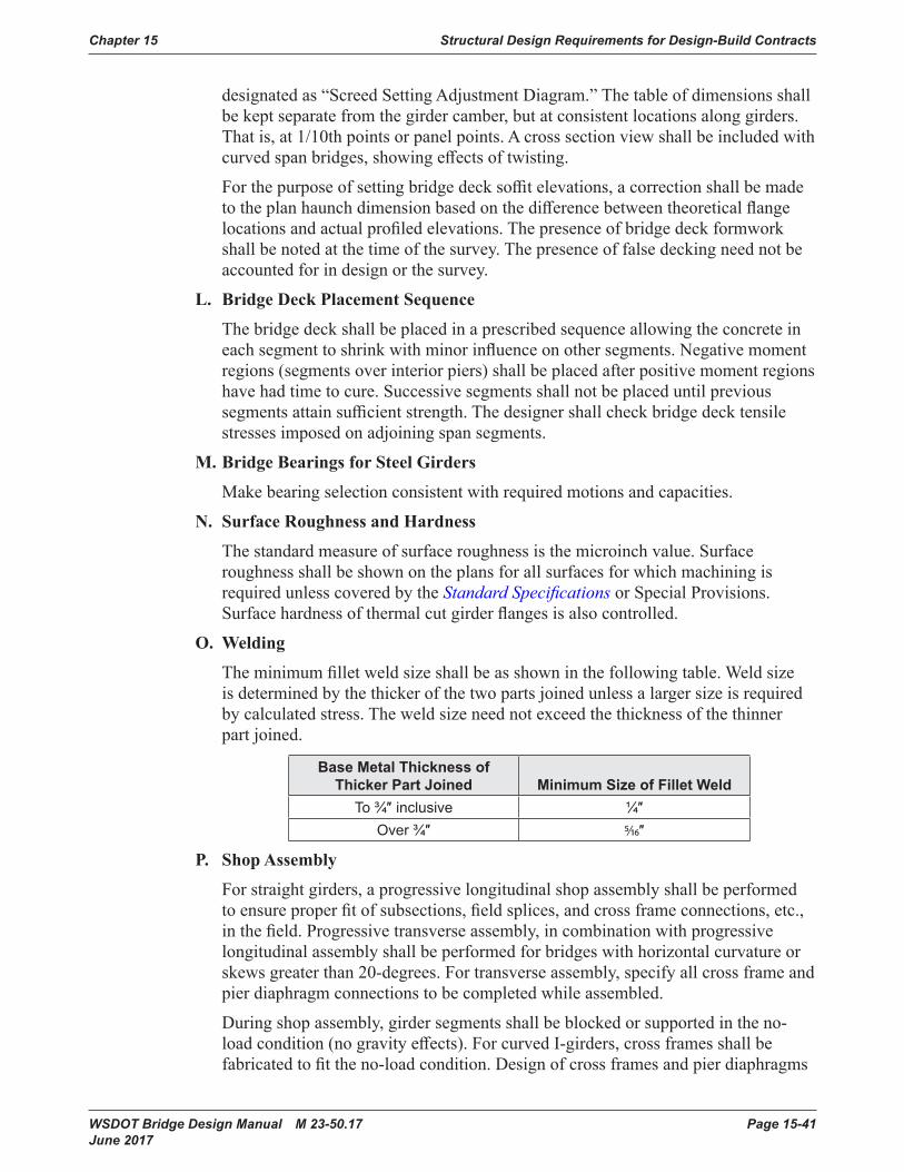
Chapter 15 Structural Design Requirements for Design-Build Contracts
WSDOT Bridge Design Manual M 23-50.17 Page 15-41 June 2017
designatedas“ScreedSettingAdjustmentDiagram.”Thetableofdimensionsshallbekeptseparatefromthegirdercamber,butatconsistentlocationsalonggirders.Thatis,at1/10thpointsorpanelpoints.Acrosssectionviewshallbeincludedwithcurvedspanbridges,showingeffectsoftwisting.
Forthepurposeofsettingbridgedecksoffitelevations,acorrectionshallbemadetotheplanhaunchdimensionbasedonthedifferencebetweentheoreticalflangelocationsandactualprofiledelevations.Thepresenceofbridgedeckformworkshallbenotedatthetimeofthesurvey.Thepresenceoffalsedeckingneednotbeaccountedforindesignorthesurvey.
L. BridgeDeckPlacementSequence
Thebridgedeckshallbeplacedinaprescribedsequenceallowingtheconcreteineachsegmenttoshrinkwithminorinfluenceonothersegments.Negativemomentregions(segmentsoverinteriorpiers)shallbeplacedafterpositivemomentregionshavehadtimetocure.Successivesegmentsshallnotbeplaceduntilprevioussegmentsattainsufficientstrength.Thedesignershallcheckbridgedecktensilestressesimposedonadjoiningspansegments.
M. Bridge Bearings for Steel Girders
Makebearingselectionconsistentwithrequiredmotionsandcapacities.
N. Surface Roughness and Hardness
Thestandardmeasureofsurfaceroughnessisthemicroinchvalue.SurfaceroughnessshallbeshownontheplansforallsurfacesforwhichmachiningisrequiredunlesscoveredbytheStandard SpecificationsorSpecialProvisions.Surfacehardnessofthermalcutgirderflangesisalsocontrolled.
O. Welding
Theminimumfilletweldsizeshallbeasshowninthefollowingtable.Weldsizeisdeterminedbythethickerofthetwopartsjoinedunlessalargersizeisrequiredbycalculatedstress.Theweldsizeneednotexceedthethicknessofthethinnerpartjoined.
Base Metal Thickness of Thicker Part Joined Minimum Size of Fillet Weld
To ¾″ inclusive ¼″Over ¾″ 5/16″
P. ShopAssembly
Forstraightgirders,aprogressivelongitudinalshopassemblyshallbeperformedtoensureproperfitofsubsections,fieldsplices,andcrossframeconnections,etc.,inthefield.Progressivetransverseassembly,incombinationwithprogressivelongitudinalassemblyshallbeperformedforbridgeswithhorizontalcurvatureorskewsgreaterthan20-degrees.Fortransverseassembly,specifyallcrossframeandpierdiaphragmconnectionstobecompletedwhileassembled.
Duringshopassembly,girdersegmentsshallbeblockedorsupportedintheno-loadcondition(nogravityeffects).ForcurvedI-girders,crossframesshallbefabricatedtofittheno-loadcondition.Designofcrossframesandpierdiaphragms
Structural Design Requirements for Design-Build Contracts Chapter 15
Page 15-42 WSDOT Bridge Design Manual M 23-50.17 June 2017
shalltakeintoaccounttwistandrotationsofwebsduringconstruction.Thissituationshouldbecarefullystudiedbyfiniteelementanalysistodetermineamountandtypeofmovementanticipatedduringconstruction.Unlikecurvedgirdersrotatingawayfromplumbatmidspan,girderwebsforskewedconstructionshallbekeptplumbatpiers.
Forbridgeswithskewsgreaterthan20-degrees,thefitofgirdersegments,crossframes,andpierdiaphragmsshallbecarefullyanalyzedduringdesigntoselecttheproperfitcondition,whichshallbeeithertheno-loadconditionofthesteeldeadloadcondition.Thedetailing,fabrication,andshopassemblyshallbespecifiedtomatchtheconditionusedintheanalysisanddesign.
15.6.4 Plan DetailsA. General
Detailingpracticeshallfollowindustrystandards.DesignationsforstructuralsteelcanbefoundinAISCDetailing for Steel Construction.DetailingshallalsoconformtonationalunifiedguidelinespublishedbyAASHTO/NSBASteel Bridge Collaboration.
Connectionsinthefieldshallbebolted.Crossframemembersmaybeshopboltedorweldedassembliesandshallbeshippedtothefieldinoneunit.Connectionsofboltedcrossframeassembliesshallbefullytensionedpriortoshipping.Crossframeassembliesshallbefieldboltedtogirdersduringerection.
B. FramingPlan
TheFramingPlanshallshowtiesbetweenthesurveyline,girderlines,backsofpavementseats,andcenterlinesofpiers.Locatepanelpoints(crossframelocations).Providegeometry,bearinglines,andtransverseintermediatestiffenerlocations.Showfieldsplicelocations.Mapoutdifferentlateralconnectiondetails.
C. Girder Elevation
TheGirderElevationisusedtodefineflanges,webs,andtheirsplicelocations.Showshearconnectorspacing,location,andnumberacrosstheflange.Showshearconnectorlocationsonflangespliceplatesorspecificallycalloutwhennoconnectorsarerequiredonspliceplates.Locatetransversestiffenersandshowwheretheyarecutshortoftensionflanges.ShowthetensionregionsofthegirderswithaVforthepurposeoforderingplatematerial,inspectionmethods(NDE),andBridge Welding Codeacceptancecriteria.Identifytensionweldedbuttsplicesforwhichradiographicexamination(RT)isrequired.Permissibleweldedwebsplicesshallbeshown.Iftherearefracturecriticalcomponents,theyshallbeclearlyidentifiedasFCM.
D. TypicalGirderDetails
Specificsheetsshallbedevotedtoshowingtypicaldetailstobeusedthroughoutthegirders.Suchdetailsincludethewelddetails,variousstiffenerplatesandweldconnections,locationsofoptionalwebsplices,anddripplatedetails.Fieldsplicesforflangesshallaccommodateweblocationtoleranceof±¼″inaccordancewiththeAWSBridge Welding Code3.5.1.5.Allowaminimumof¼″foroutofpositionwebplus⅜″forfilletweld,oratotalof⅝″minimumclearbetweentheoretical
Chapter 15 Structural Design Requirements for Design-Build Contracts
WSDOT Bridge Design Manual M 23-50.17 Page 15-43 June 2017
faceofwebandedgeofspliceplate.Thebottomflangespliceplateshallbesplittoallowmoisturetodrain(use4equalbottomflangespliceplates).Thefillplatedoesnotneedtobesplit.
Verticalstiffenersusedtoconnectcrossframesshallbeweldedtotopandbottomflangestoreduceout-of-planebendingoftheweb.Allstiffenersshallbecoped,clipped(orcutshortinthecaseoftransversestiffenerswithoutcrossframes)adistancebetween4twand6twtoprovidewebflexibility,inaccordancewithAASHTOLRFDArticle6.10.11.1.1.
F. CrossFrameDetails
Showmembersizes,geometrics(worklinesandworkpoints),andconnectiondetails.Doubleanglesshallnotbeusedforcrossframes.Crossframesshallbecompletesubassembliesforfieldinstallation.
Internalcrossframesandtoplateralsystemsforboxgirdersareshopwelded,primarily.Allconnectiontypesshallbecloselyexaminedfordetailconflictandweldaccess.Clearancebetweenbridgedeckformingandtoplateralmembersshallbeconsidered.
G. CamberDiagramandBearingStiffenerRotation
Cambercurvesshallbedetailedtoprovidedimensionsattenthpoints.Dimensionsmayalsobegivenatcrossframelocations.Inordertoplacebearingstiffenersintheverticalpositionafterbridgedeckplacement,showexpectedgirderrotationsatpiers.
Showdeflectioncamberonly.GeometriccamberforprofilegradeandsuperelevationwillbecalculatedbytheshopdetailerfromhighwayalignmentshownontheLayoutsheets.
Aseparatediagramandtable,withbridgecrosssection,shallbeincludedtoshowhowelevationsatedgesofdeckcanbedeterminedjustbeforeconcreteplacement.Thiswillgiveadjustmentstoaddtoprofilegrades,basedonremainingdeadloaddeflections,withdeckformworkandreinforcingbeingpresent.
H. Bridge Deck
NewbridgedecksforsteelI-girdersorboxgirdersshalluseDeckProtectionSystem1.
Thebridgedeckshallbedetailedinsectionandplanviews.Forcontinuousspans,showasectionshowingnegativemomentlongitudinalreinforcing.Theplanviewsshalldetailtypicalreinforcingandcutofflocationsfornegativemomentsteel.Negativemomentsteelshallnotbeterminatedatonelocation.
Thepaddimensionisassumedtobeconstantthroughoutthespanlength.Ideally,thegirderiscamberedtocompensatefordeadloadsandverticalcurves.However,fabricationanderectiontolerancesresultinconsiderabledeviationfromtheoreticalelevations.Thepaddimensionisthereforeconsideredonlyanominalvalueandisadjustedasneededalongthespanoncethesteelhasbeenerectedandprofiled.Thescreedfortheslabistobesettoproducecorrectroadwayprofile.TheplansshallreferencethisprocedurecontainedinStandard Specifications Section6-03.3(39).Thepaddimensionistobenotedasnominal.
Structural Design Requirements for Design-Build Contracts Chapter 15
Page 15-44 WSDOT Bridge Design Manual M 23-50.17 June 2017
I. HandrailDetails,InspectionLighting,andAccess
WhenrequiredbytheRFPCriteria,includehandrailswithtypicalgirderdetails.Locationsmaybeadjustedtoavoidconflictswithotherdetailssuchaslargegussetplates.Boxgirdersrequirespecialconsiderationforinspectionaccess.Accessholesorhatchesshallbedetailedtoexcludebirdsandthepublic.Theyshallbepositionedwhereladderscanbeusedtogainaccess.Locatehatchesingirderwebsatabutments.Provideforroundtripaccessandpenetrationsatallintermediatediaphragms.Accessforremovingbridgedeckformworkshallbeprovided.Boxgirdersshallhaveelectrical,inspectionlighting,andventilationdetailsfortheaidofinspectionandmaintenance.RefertotheDesign ManualChapter1040forbridgeinspectionlightingrequirements.
Tofacilitateinspection,interiorpaintshallbeFederalStandard595colornumber17925(white).One-wayinspectionofallinteriorspacesshallbemadepossiblebyroundtripinadjoininggirders.Thisrequiressomeformofwalkwaybetweenboxesandhatchoperationfrombothsides.Iflocksareneeded,theymustbekeyedtoonemaster.Airventsshallbeplacedalonggirderwebstoallowfreshairtocirculate.
J. Box Girder Details
Provideatoplateralsystemineachbox,fulllengthofagirder.
Thetoplateralsshallbebolteddirectlytothetopflangeorintermediateboltedgussetplate(inwhichcase,thelateralmembersmaybeweldedtothegussetplate).Inordertomaximizetheclearancefordeckforms,alllateralconnectionsshallprogressdownfromthebottomsurfaceofthetopflange.Thehaunchdistancebetweentopofwebanddecksoffitshallbe6″orgreatertoallowdeckformingtocleartoplateralmembers.
Tofacilitatecontinuousweldingofthebottomflangetowebs,thestiffenersshallbeheldbackandattachedtothebottomflangebyamemberbroughtinafterthebottomlongitudinalweldsarecomplete.
Theoffsetbetweencenterofwebandedgeofbottomflangeshallbe2″
Useteeshapes,eithersinglyorinpairs,forstiffeningwidebottomflanges.
Boxgirderinsideclearheightshallbe5feetormoretoprovidereasonableinspectionaccess.Lessthan5feetinsideclearheightisnotbepermitted.
Drainholesshallbeinstalledatalllowpoints.
Geometricsforboxesshallbereferencedtoasingleworkline,unlessboxwidthtapers.Theboxcrosssectionremainstiedtoacenterlineintersectingthisworklineandnormaltothebridgedeck.Thesectionrotateswithsuperelevationtransitionratherthanwarping.
WSDOT Bridge Design Manual M 23-50.17 Page 15-45 June 2017
15.7 Substructure Design15.7.1 General Substructure Considerations
A. Foundation Seals
Thebottomofseal,ifused,shallbenohigherthanthescourdepthelevation.
B. Scour
Thedesignfloodlocalscourdepth(l00yearevent)shallbeincludedintheStrengthIlimitstateanalysis,andthecheckfloodlocalscourdepth(500yearevent)shallbeincludedintheExtremeEventIIlimitstateanalysis.Whenincludingtheeffectsofscour,thedesignshallconsiderthelossofoverburdenandfoundationsideresistance.
Wherelateralstreammigrationisapossibility,thedesignshallincludeareliability-basedestimateoftheeffectsonthestructure.
C. CombinationofExtremeEventEffects
1. Downdrag
SeismicsoilliquefactioninduceddowndragforcesshallbeincludedintheExtremeEventIlimitstate.Downdragloadsmaybedecoupledfromtheinertialandoverstrengthloadeffects.
2. LateralGroundDisplacement
Wherelateralgrounddisplacement(e.g.lateralspreadingandlateralflow)isexpected,thegrounddisplacementmaybedecoupledfromtheinertialandoverstrengthloadeffects.SeeWSDOTGeotechnical Design ManualSections6.4.2.8and6.5.4.2foradditionalguidanceoncombiningloadswhenlateralgrounddisplacementoccurs.
3. Scour
Theeffectsoflocalscourshallbecombinedwithearthquakeloading.AttheExtremeEventIlimitstate,thedesignshallconsiderascourdepthequalto25percentofthedesignfloodscourdepth.
15.7.2 Foundation Modeling for Seismic LoadsA. General
BridgemodelingforseismiceventsshallbeinaccordancewithrequirementsoftheAASHTOSEISMICSection5.
Ifliquefactionisadesigncondition,thebridgeshallbeanalyzedusingboththestaticandliquefiedsoilconditionsinaccordancewithAASHTOSEISMICSection6.8.
TheLPileprogrammaybeusedforpileandshaftsupportedfoundations.However,theLiquefactionoptionandLiquefiedSandsoiltypeintheLPILEprogramshallnotbeused.
Structural Design Requirements for Design-Build Contracts Chapter 15
Page 15-46 WSDOT Bridge Design Manual M 23-50.17 June 2017
B. BridgeModelSectionProperties
Ingeneral,grosssectionpropertiesmaybeassumedforallmembers,exceptconcretecolumnsandotherductilereinforcedconcretemembers.Seismicresponseanalysisfordeepfoundationsshallbebasedonabracketedapproachusingastiffsubstructureresponseandasoftsubstructureresponse.
1. CrackedPropertiesforColumns
EffectivesectionpropertiesshallbeinaccordancewiththeAASHTOSEISMICSection5.6.
2. ShaftProperties
Theshaftconcretestrengthandconstructionmethodsleadtosignificantvariationinshaftstiffnessdescribedasfollows:
Forastiffsubstructureresponse:
1. Use1.5ƒ′ctocalculatethemodulusofelasticity.
2. UseIgbasedontheactualshaftdiameter.
3. Whenpermanentcasingisused,increaseshaftIgusingthetransformedareaofthecasing.
Forasoftsubstructureresponse:
1. Useƒ′ctocalculatethemodulusofelasticity.
2. UseIgbasedontheactualshaftdiameter.Alternatively,Iemaybeusedwhenitisreflectiveoftheactualloadeffectsintheshaft.
3. Whenpermanentcasingisused,increaseshaftIgusingthetransformedareaofthecasing.
3. Cast-in-PlacePileProperties
Forastiffsubstructureresponse:
1. Use1.5ƒ′ctocalculatethemodulusofelasticity.
2. UsethepileIgplusthetransformedcasingmomentofinertia.
Forasoftsubstructureresponse:
1. Use1.0ƒ′ctocalculatethemodulusofelasticity.
2. UsepileIg,neglectingcasingproperties.
C. SpreadFootingModelingMethods
ThemethodforcalculatingfootingspringsisgiveninSection7.2.7.
D. DeepFoundationModelingMethods
ThemethodusedtomodeldeepfoundationsshallconformtoAASHTOSEISMICSection5.3.
1. GroupEffects
ThereductionfactorsforlateralresistanceduetotheinteractionofdeepfoundationmembersisprovidedinAASHTOSEISMICSection8.12.2.5.
Chapter 15 Structural Design Requirements for Design-Build Contracts
WSDOT Bridge Design Manual M 23-50.17 Page 15-47 June 2017
2. ShaftCapsandPileFootings
Inareaspronetoscourorlateralspreading,thepassiveresistanceofcapsandpile-supportedfootingsshallbeneglected.
E. DesignofDeepFoundationsforLateralForces
1. DeterminationofTipElevations
Aparametricstudyoranalysisshallbeperformedtoevaluatethesensitivityofthedepthoftheshaftorpiletothegroundleveldisplacementofthestructureinordertodeterminethedepthrequiredforstable,proportionatelateralresponseofthestructure.
2. Design for Lateral Loads
Thestructuraldesignofshaftsandpilesshallconsiderthefollowingconditionsattheapplicablelimitstate:
a. Staticsoilpropertieswithbothstiffandsoftshaftorpileproperties.
b. Dynamicordegradedsoilpropertieswithbothstiffandsoftshaftorpileproperties.
c. Liquefiedsoilpropertieswithbothstiffandsoftshaftorpileproperties.Whenlateralspreadingispossible,additionalloadingconditionswillneedtobeanalyzed.
d. Scourconditionwithstiffandsoftshaftorpileproperties.
15.7.3 Column DesignA. Shear Design
AtStrengthlimitstates,sheardesignshallfollowthe“SimplifiedProcedureforNonprestressedSections”inAASHTOLRFD Section5.8.3.4.1.
B. ColumnSilos
Duetotheconstructionandinspectioncomplicationsofcolumnsilos,theDesign-BuildershallattempttomeetbalancedstiffnessandframegeometryrequirementsbytheothermethodssuggestedinSection4.1.4oftheAASHTOSEISMIC priortouseofcolumnsilos.ColumnsilosshallmeettherequirementsofSection7.3.8.
C. LongitudinalReinforcement
Themaximumreinforcementratioshallbe0.04inSDCsA,B,CandD.Theminimumreinforcementratioshallbe0.007forSDCA,B,andCandshallbe0.01forSDCD.
ForbridgesinSDCA,ifoversizedcolumnsareusedforarchitecturalreasons,theminimumreinforcementratioofthegrosssectionmaybereducedto0.005,providedallloadscanbecarriedonareducedsectionwithsimilarshapeandthereinforcementratioofthereducedsectionisequaltoorgreaterthan0.01and0.133ƒ′c/ƒy.Thecolumndimensionsaretobereducedbythesameratiotoobtainthesimilarshape.
Thereinforcementshallbeevenlydistributedandsymmetricwithinthecolumn.
Structural Design Requirements for Design-Build Contracts Chapter 15
Page 15-48 WSDOT Bridge Design Manual M 23-50.17 June 2017
D. LongitudinalReinforcementSplices
Nosplicesareallowedwhentherequiredlengthoflongitudinalreinforcementislessthantheconventionalmilllengthof60-feet.Splicingoflongitudinalreinforcementshallbeoutsidetheplastichingeregions.ButinSDCA,splicesneedonlybelocatedaminimumof1.5timesthecolumndiameterfromthetopandbottomofthecolumn.
ForbridgesinSDCAandSDCB,nolapsplicesshallbeusedfor#14or#18bars(suchsplicesshallbemechanicalsplicesconformingtoStandard Specifications Section6-02.3(24)C).Eitherlapormechanicalsplicesmaybeusedfor#11barsandsmaller.LapsplicesshallbedetailedasClassBsplices.Thespacingoftransversereinforcementoverthelengthofalapspliceshallnotexceed4-inchesorone-quarteroftheminimummemberdimension.
ForbridgesinSDCCandSDCD,barsshallbesplicedusingmechanicalsplicesconformingtoStandard SpecificationsSection6-02.3(24)F.Splicesshallbestaggered.Thedistancebetweensplicesofadjacentbarsshallbegreaterthanthemaximumof20-bardiametersor24-inches.
E. LongitudinalReinforcementDevelopment
1. Crossbeams
DevelopmentoflongitudinalreinforcementshallbeinaccordancewithAASHTOSEISMICSection8.8.4.Columnlongitudinalreinforcementshallbeextendedintocrossbeamsascloseaspracticablypossibletotheoppositefaceofthecrossbeam.
2. Footings
Longitudinalreinforcementatthebottomofacolumnshouldextendintothefootingandrestonthebottommatoffootingreinforcementwithstandard90degreehooks.Inaddition,developmentoflongitudinalreinforcementshallbeinaccordancewithAASHTOSEISMICSection8.8.4andAASHTOLRFDSection5.11.2.1.
3. Drilled Shafts
EmbedmentshallbespecifiedusingTRACReportWA-RD417.1titled“NoncontactLapSplicesinBridgeColumn-ShaftConnections”.TherequirementsoftheAASHTOSEISMICSection8.8.10fordevelopmentlengthofcolumnbarsextendedintooversizedpileshaftsforSDCCandDshallnotbeused.
ThemodificationfactorinAASHTOLRFDSection5.11.2.1.3thatallowsldtobedecreasedbytheratioof(As required)/(As provided),shallnotbeused.
F. TransverseReinforcement
1. General
Alltransversereinforcementincolumnsshallbedeformed.ColumnsinSDCAandBmayusespirals,circularhoops,orrectangularhoopsandcrossties.ColumnsinSDCCandDshallusecircularhoopreinforcement.However,rectangularhoopswithtiesmaybeusedwhenlarge,oddshapedcolumnsectionsarerequired.
Chapter 15 Structural Design Requirements for Design-Build Contracts
WSDOT Bridge Design Manual M 23-50.17 Page 15-49 June 2017
2. SpiralSplicesandHoops
Weldedlapsshallbeusedforsplicingandterminatingspirals.Spiralsorbutt-weldedhoopsarerequiredwithinplastichingeregions.Splicesshallbestaggered.Also,whereinterlockinghoopsareusedinrectangularornon-circularcolumns,thesplicesshallbelocatedinthecolumninterior.Circularhoopsforcolumnsshallbeshopfabricatedusingamanualdirectbuttweldorresistancebuttweld.Fieldweldedsplicesandterminationweldsofspiralsofanysizebararenotpermittedintheplastichingeregion,includingazoneextending2’-0”intotheconnectedmember.
G. ReducedColumnSection
ColumnswithoverstrengthforcereducingdetailsshallbedesignedinaccordancewithSection7.3.7.
15.7.4 CrossbeamTwo-stageintegralnon-prestressedcrossbeamsshallbedesignedinaccordancewithSection7.4.1.
15.7.5 Abutment Design and DetailsA. General
1. Bent-TypeAbutments
Abutmentsthatincludeabentcapsupportedoncolumnsorextendedpilesorshaftsshallnotbeused.
2. AbutmentsonStructuralEarth(SE)WallsandGeosyntheticWalls
Bridgeabutmentsmaybesupportedonstructuralearthwallsandgeosyntheticwalls.AbutmentssupportedonthesewallsshallbedesignedinaccordancewiththerequirementsofthisRFPandthefollowingdocuments(listedinorderofimportance):• WSDOTGeotechnical Design ManualSection15.5.3.5• AASHTOLRFD• Design and Construction of Mechanically Stabilized Earth Walls
and Reinforced Soil Slopes,VolumeIandII,FHWA-NHI-10-024,FHWA-NHI-10-025
Wallsdirectlysupportingbridgeabutmentspreadfootingsshallbe30feetorlessintotalheight,measuredfromthetopofthefascialevelingpadtothebottomofthebridgeabutmentfooting.
B. EmbankmentandBackfill
1. General Clearances
TheminimumclearancesfortheembankmentatthefrontfaceofabutmentsshallbeasindicatedonStandardPlansA-50.10.00throughA-50.40.00.
Theminimumclearancebetweenthebottomofthesuperstructureandtheembankmentbelowshallbe3’-0”forgirderbridgesand5’-0”fornon-girder,slab,andboxgirderbridges.
Structural Design Requirements for Design-Build Contracts Chapter 15
Page 15-50 WSDOT Bridge Design Manual M 23-50.17 June 2017
2. AbutmentsonSEWallsandGeosyntheticWalls
ClearancesaroundbridgeabutmentsshallbeprovidedasshowninFigure7.5.2-1.Concreteslopeprotectionshallbeprovided.
3. DrainageandBackfill
3″diameterweepholesshallbeprovidedinallbridgeabutmentwalls.Theseshallbelocated6″abovethefinishgroundlineat12′oncenter.Incaseswheretheverticaldistancebetweenthetopofthefootingandthefinishgroundlineisgreaterthan10′,additionalweepholesshallbeprovided6″abovethetopofthefooting.
Gravelbackfillforwallsshallbeprovidedbehindallbridgeabutments.A3′widthofgravelbackfillshallbeprovidedbehindthecantileverwingwalls.Anunderdrainpipeandgravelbackfillfordrainshallbeprovidedbehindallbridgeabutmentsexceptabutmentsonfillswithastemwallheightof5′orless.
C. AbutmentLoading
1. Earthquake Load
EQ
Forbearingpressureandabutmentstabilitychecks,theseismicinertialforceoftheabutment,PIR,shallbecombinedwiththeseismiclateralearthpressureforce,PAE,asdescribedinAASHTOLRFDSection11.6.5.1.Forstructuraldesignoftheabutment,theseismicinertialforce,PIR,maybetakenas0.0.
Forconventionalfootingsupportedabutments,theseismichorizontalaccelerationcoefficient,kh,shallbetakenasonehalfoftheseismichorizontalaccelerationcoefficientassumingzerodisplacement,kh0.TheseismicactiveearthpressureshallbedeterminedusingtheMononobe-Okabemethod,asdescribedinAASHTOLRFDAppendixA11.
Forpile-orshaft-supportedabutmentsorotherabutmentsthatarenotfreetotranslate1.0inchto2.0inchduringaseismicevent,useaseismichorizontalaccelerationcoefficient,kh,of1.5timesthesite-adjustedpeakgroundacceleration.
Theseismicverticalaccelerationcoefficient,kv,shallbetakenas0.0forabutmentdesign.
2. Bearing Forces
TU
Forstrengthdesign,thebearingshearforcesshallbebasedon½oftheannualtemperaturerange.
D. AbutmentDetails
1. Bearing Seats
Thebearingseatsshallhaveaminimumedgedimensionof3″fromthebearingsshallandsatisfytherequirementsofAASHTOLRFDSection4.7.4.4.OnLabutments,thebearingseatshallbeslopedawayfromthebearingstopreventpondingatthebearings.
Chapter 15 Structural Design Requirements for Design-Build Contracts
WSDOT Bridge Design Manual M 23-50.17 Page 15-51 June 2017
2. TransverseGirderStops
Allsuperstructuresshallberestrainedagainstlateraldisplacementattheabutmentsandintermediateexpansionpiers.AllprestressedgirderbridgesinWesternWashington(withinandwestoftheCascademountainrange)shallhavegirderstopsbetweenallgirdersatabutmentsandintermediateexpansionpiers.GirderstopsshallbefullwidthbetweengirderflangesexcepttoaccommodatebearingreplacementrequirementsasspecifiedinChapter9. Girderstopsaredesignedusingashearstrengthresistancefactorshallbeϕs = 0.9.
3. AbutmentWalls
Whenconstructionjointsarelocatedinthemiddleoftheabutmentwall,apourstriporanarchitecturalrevealshouldbeusedforacleanappearance.AASHTOLRFDSection5.10.8shallbefollowedfortemperatureandshrinkagereinforcementrequirementsnearconcretesurfacesexposedtodailytemperaturechangesandinstructuralmassconcrete.Theminimumcrosstiereinforcementinabutmentwallsshallbe#4tiebarswith135°hooks,spacedatapproximately2′-0″center-to-centerverticallyandhorizontally.
15.7.6 Abutment Wing Walls and Curtain WallsWallfootingthicknessshallnotbelessthan1’-6”
15.7.7 Footing DesignA. General Footing Criteria
See Figure7.7.1-1forfootingcoverrequirements.FootingssupportedonSEwallsorgeosyntheticwallsshallhaveaminimumof6″ofcover.
B. SpreadFootingDesign
1. Foundation Design
a. Bearing Stress
ThemaximumeffectivewidthforcalculatinguniformbearingstressislimitedtoC+2DasshowninFigure7.7.4-3.
2. Structural Design
a. Footing Thickness and Shear
Theminimumfootingthicknessshallbe1′-0″.Theminimumplandimensionshallbe4′-0″.
b. VerticalReinforcement
Verticalreinforcementshallbedevelopedintothefootingtoadequatelytransferloadstothefooting.Verticalrebarshallbebent90°andextendtothetopofthebottommatoffootingreinforcement.Barsintensionshallbedevelopedusing1.25Ld.Barsincompressionshalldevelopalengthof1.25 Ld,priortothebend.Wherebarsarenotfullystressed,lengthsmaybereducedinproportion,butshallnotbelessthan¾Ld.
Structural Design Requirements for Design-Build Contracts Chapter 15
Page 15-52 WSDOT Bridge Design Manual M 23-50.17 June 2017
c. BottomReinforcement
Reinforcementshallnotbelessthan#6barsat12″centerstoaccountforunevensoilconditionsandshrinkagestresses.
d. TopReinforcement
Topreinforcementforfootingsdesignedfortwo-wayactionshallnotbelessthan#6barsat12″centers,ineachdirectionwhiletopreinforcementforbearingwalldesignedforone-wayactionshallnotbelessthan#5barsat12″centersineachdirection.
C. Pile-SupportedFootingDesign
Theminimumfootingthicknessshallbe2′-0″.Theminimumplandimensionshallbe4′-0.
1. PileEmbedment,Clearance,andRebarMatLocation
Cast-in-placeconcretepileswithreinforcingextendingintofootingsareembeddedaminimumof6″.Theclearanceforthebottommatoffootingreinforcementshallbe1½″betweenthereinforcingandthetopofthepileforCIPpilefootings.SeeFigure7.7.5-2fortheminimumpileclearancetotheedgeoffooting.
2. Concrete Design
Indeterminingtheproportionofpileloadtobeusedforcalculationofshearstressonthefooting,anypilewithitscenter6″ormoreoutsidethecriticalsectionshallbetakenasfullyactingonthatsection.Anypilewithitscenter6″ormoreinsidethecriticalsectionshallbetakenasnotactingforthatsection.Forlocationsinbetween,thepileloadactingshallbeproportionedbetweenthesetwoextremes.
15.7.8 ShaftsA. Axial Resistance
Thebridgeplansshallincludetheendbearingandsidefrictionnominalshaftresistancefortheservice,strength,andextremeeventlimitstatesintheGeneralNotes,asshowninFigure7.8-1-1.
1. AxialResistanceGroupReductionFactors
ThegroupreductionfactorsforaxialresistanceofshaftsforthestrengthandextremeeventlimitstatesshallbetakenasshowninTable7.8.1.1-1.Thesereductionfactorspresumethatgoodshaftinstallationpracticesareusedtominimizeoreliminatetherelaxationofthesoilbetweenshaftsandcaving.Ifthiscannotbeadequatelycontrolledduetodifficultsoilsconditionsorforotherconstructabilityreasons,lowergroupreductionfactorsshallbeusedasrecommendedbythegeotechnicalengineerofrecord.Thesegroupreductionfactorsapplytobothstrengthandextremeeventlimitstates.FortheservicelimitstatetheinfluenceofthegrouponsettlementasrequiredintheAASHTOLRFDandtheAASHTOSEISMICarestillapplicable.
Chapter 15 Structural Design Requirements for Design-Build Contracts
WSDOT Bridge Design Manual M 23-50.17 Page 15-53 June 2017
B. Structural Design and Detailing
1. Drilledshaftsshallbedesignedforthelesseroftheplasticforcesor1.2timestheelasticseismicforcesofthecolumnaboveinsinglecolumn/singleshaftfoundations.
2. ConcreteClass5000Pshallbespecifiedfortheentirelengthoftheshaftforwetordryconditionsofplacement.
3. Whenshaftsareconstructedinwater,theconcretespecifiedforthecasingshoringsealshallbeClass4000W.
4. Theassumedconcretecompressivestrengthmaybetakenas0.85ƒ′cforstructuraldesignofshafts.Forseismicdesign,theexpectedcompressivestrengthmaybetakenas1.3timesthisvalueinaccordancewithAASHTOSeismicSection8.4.4.
5. Thepresenceofpermanentsteelcasingshallbetakenintoaccountintheshaftdesign(i.e.forstiffness,andetc.),butthestructuralcapacityofpermanentsteelcasingshallnotbeconsideredforstructuraldesignofdrilledshaftsunlessthedesignconformstoSection15.
6. Minimumcoverrequirementsshallbeasspecifiedbelow:• Diameterlessthanorequalto3′-0″=3″• Diametergreaterthan3′-0″andlessthan5′-0″=4″• Diametergreaterthanorequalto5′-0″=6″
7. Theclearspacingbetweenspiralsandhoopsshallnotbelessthan6″ormorethan9″.Theclearspacingbetweenspiralsorhoopsmaybereducedinthesplicezoneinsinglecolumn/singleshaftconnectionsiftheconcreteisvibrated.
8. ThevolumetricratioandspacingrequirementsoftheAASHTOSEISMICforconfinementneednotbemet.
9. #7through#9weldedlapsplicedhoopsareacceptabletouseprovidedtheyarenotlocatedinpossibleplastichingeregions.Weldedsplicesinhoopsforshaftsshallbecompletedpriortoassemblyoftheshaftsteelreinforcingcage.Whenhoopsareused,theplansshallshowastaggeredsplicepatternaroundtheperimeteroftheshaftsothatnotwoadjacentsplicesarelocatedatthesamelocation.
10.Insinglecolumn/singleshaftconfigurations,thespacingoftheshafttransversereinforcementinthesplicezoneshallmeettherequirementsoftheTRACReporttitled,“Noncontact Lap Splices in Bridge Column-Shaft Connections”.Thefactorkrepresentstheratioofcolumntensilereinforcementtototalcolumnreinforcementatthenominalresistance.Intheupperhalfofthesplicezone,kshallbetakenas1.0.Inthelowerhalfofthesplicezone,thisrationcouldbedeterminedfromacolumnmoment-curvatureanalysis.
Structural Design Requirements for Design-Build Contracts Chapter 15
Page 15-54 WSDOT Bridge Design Manual M 23-50.17 June 2017
11.Longitudinalreinforcementshallbeprovidedforthefulllengthofdrilledshafts.Theminimumlongitudinalreinforcementinthesplicezoneofsinglecolumn/singleshaftconnectionsshallbethelargerof0.75percentAgoftheshaftor1.0percentAgoftheattachedcolumn.Theminimumlongitudinalreinforcementbeyondthesplicezoneshallbe0.75percentAgoftheshaft.Theminimumlongitudinalreinforcementinshaftswithoutsinglecolumn/singleshaftconnectionsshallbe0.75percentAgoftheshaft.
12.Theclearspacingbetweenlongitudinalreinforcementshallnotbelessthan6″ormorethan9″.Ifashaftdesignisunabletomeetthisminimumrequirement,alargerdiametershaftshallbeconsidered.
13.Mechanicalsplicesinlongitudinalbarsshallbeplacedinlowstressregionsandstaggered2′-0″minimum.
14.Whereundersizedpermanentslipcasingisused,provideaminimumofconcretecoverof3″forshaftswithadiameterof4′-0″andlargerand1½″forshaftswithadiameterlessthan4′-0″.
15.ReinforcingbarcentralizersshallbedetailedintheplansasshowninSection7.8.2-5.
15.7.9 Piles and PilingA. PileTypes
PilesfornewpermanentbridgesshallbeCIPconcretepiles.
B. PileGroups
Theminimumcenter-to-centerspacingofpilesshallbe30″or2.5pilediameters.
C. Battered Piles
Batteredpilesshallnotbeusedtoresistlateralloadsforpermanentbridgefoundations.
D. Structural Design and Detailing of CIP Concrete Piles
1. ConcreteClass5000PshallbespecifiedforCIPconcretepiles.Thetop10′ofconcreteinthepileshallbevibrated.
2. Forstructuraldesign,thereinforcementaloneshallbedesignedtoresistthetotalmomentthroughoutthelengthofpilewithoutconsideringstrengthofthesteelcasing.Theminimumreinforcementshallbe0.75percentAg forSDCB,CandDandshallbeprovidedforthefulllengthofthepile.MinimumclearancebetweenlongitudinalbarsshallmeettherequirementsinAppendix5.1-A2.
3. Ifthepiletofooting/capconnectionisnotaplastichingezonelongitudinalreinforcementneedonlyextendabovethepileintothefooting/capadistanceequalto1.0ld(tension).Ifthepiletofooting/capconnectionisaplastichingezonelongitudinalreinforcementshallextendabovethepileintothefooting/capadistanceequalto1.25ld.
Chapter 15 Structural Design Requirements for Design-Build Contracts
WSDOT Bridge Design Manual M 23-50.17 Page 15-55 June 2017
4. Transversespiralreinforcementshallbedesignedtoresistthemaximumshearinthepile.Theminimumspiralshallbea#4barat9″pitch.Ifthepiletofooting/capconnectionisnotaplastichingezonethevolumetricrequirementsofAASHTOLRFDSection5.13.4.6neednotbemet.
E. PileSplices
Concretepilesplicesshalldevelopthefullflexuralandaxialresistanceofthepile.
F. Pile Resistance
ThebridgeplansshallincludetheUltimateBearingCapacity(NominalDrivingResistance,Rndr,fordrivenpiles)intonsasshowninFigure7.9.11-1.
15.7.10 Concrete-Filled Steel TubesA. DesignRequirements
Concrete-filledsteeltubes(CFST),reinforcedconcrete-filledsteeltubes(RCFST)andtheirconnectionsshallbedesignedinaccordancewithSection7.10.TheuseofCFSTandRCFSTrequiresapprovalfromtheWSDOTBridgeDesignEngineerwhenusedasaductileelementaspartofanearthquake-resistingsystem.Additionally,theplastichingemodelingparametersandmethodsmustbeapprovedbytheWSDOTBridgeDesignEngineer.
Structural Design Requirements for Design-Build Contracts Chapter 15
Page 15-56 WSDOT Bridge Design Manual M 23-50.17 June 2017
15.8 Walls and Buried Structures15.8.1 Retaining Walls
A. General
DesignofretainingwallsshallbebasedontherequirementsandguidancecitedhereinandinthecurrentAASHTOLRFD,AASHTOSEISMIC,AASHTOLRFD Bridge Construction Specifications,WSDOTGeneral&BridgeSpecialProvisionsandtheStandard Specifications M41-10unlessotherwisecitedherein.
Retainingwallsandtheircomponentsthatareinserviceforamaximumof36monthsareconsideredtobetemporary.TemporaryretainingwallsneednotbedesignedfortheExtremeEventLimitStates.
B. Loads
RetainingwallsandtheircomponentsshallbedesignedforallapplicableloadsdefinedinthecurrentAASHTOLRFDChapter3.
TheliveloadfactorforExtremeEvent-ILimitStateloadcombination,γeqasspecifiedintheAASHTOLRFDTable3.4.1-1forallpermanentretainingwallsshallbetakenequalto0.50.
C. Design of Reinforced Concrete Cantilever Retaining Walls
1. Standard Plan Reinforced Concrete Cantilever Retaining Walls
ThestandardplanreinforcedconcreteretainingwallshavebeendesignedinaccordancewiththerequirementsoftheAASHTOLRFD,4thEdition,2007,andinterimsthrough2008.SeeSection8.1foracompletelistofthedesigncriteriausedforthesewalls.DetailsforconstructionandthemaximumbearingpressureinthesoilaregivenintheStandard Plans SectionD.
2. NonStandard Reinforced Concrete Retaining Walls
Reinforcedconcreteretainingwallscontainingdesignparameterswhichexceedthoseusedinthestandardreinforcedconcreteretainingwalldesignareconsideredtobenon-standard.
Foradditionaldesigncriteria,refertoSection8.1.4B
D. Design of Cantilever Soldier Pile and Soldier Pile Tieback Walls
TypicalsoldierpilewalldetailsareprovidedintheAppendix8.1-A1.
1. GroundAnchors(Tiebacks)
Eitherthe“tributaryareamethod”orthe“hingemethod”asoutlinedinAASHTOLRFDSectionC11.9.5.1shallbeconsideredacceptabledesignprocedurestodeterminethehorizontalanchordesignforce.
Therecommendedfactoreddesignloadoftheanchor,recommendedanchorinstallationangles(typically10°–45°),noloadzonedimensions,andanyotherspecialrequirementsforwallstabilityshallbeasprovidedbythegeotechnicalinvestigationperformedfortheprojectbythegeotechnicalengineerofrecord,andtheassociatedgeotechnicalreportbasedonthatinvestigation.
Chapter 15 Structural Design Requirements for Design-Build Contracts
WSDOT Bridge Design Manual M 23-50.17 Page 15-57 June 2017
TheminimumverticalanchorspacingshallbethesameasdefinedinAASHTOLRFDSection11.9.4.2fortheminimumhorizontalanchorspacing.
Theanchorlockoffloadis60percentofthecontrollingfactoreddesignloadfortemporaryandpermanentwalls(seeGeotechnical Design Manual Chapter15).
Permanentgroundanchorsshallhavedoublecorrosionprotectionconsistingofanencapsulation-protectedtendonbondlengthasspecifiedintheWSDOTGeneralSpecialProvisions.TypicalpermanentgroundanchordetailsareprovidedintheAppendix8.1-A1.
Temporarygroundanchorsmayhaveeitherdoublecorrosionprotectionconsistingofanencapsulation-protectedtendonbondlengthorsimplecorrosionprotectionconsistingofgrout-protectedtendonbondlength.
2. Design of Soldier Pile
RefertoSection8.1.5Bfordesigncriteria
3. Design of Lagging
Ifconstructionoperationsarelikelytooccuraboveandbehindthesoldierpilewallalignment,thelaggingshallbedesignedforanadditional250psfsurchargeduetotemporaryconstructionload.
a. TemporaryTimberLagging
TemporarylaggingisasdefinedintheStandard Specifications Section616.3(6).TemporarytimberlaggingshallbedesignedinaccordancewithStandard SpecificationsSection616.3(6)B.
b. PermanentLagging
PermanentlaggingisasdefinedintheStandard Specifications Section6.16.3(6).Permanentlaggingshallbedesignedfor100percentofthelateralloadthatcouldoccurduringthelifeofthewallinaccordancewithAASHTOLRFDSections11.8.5.2and11.8.6forsimplespanswithoutsoilarching.
TimberlaggingshallbedesignedinaccordancewithAASHTOLRFDSection8.6.Thesizeeffectfactor(CFb)shallbeconsidered1.0unlessaspecificsizeisshowninthewallplans.Thewetservicefactor(CMb)shallbe0.85.Theloadappliedtolaggingshallbeappliedatthecriticaldepth.Laggingsizemaybesteppedovertheheightofthewall.
TimberlaggingdesignedasapermanentstructuralelementshallconsistoftreatedDouglasFirLarch,gradeNo.2orbetter.Hemfirwoodspecies,duetotheinadequatedurabilityinwetcondition,shallnotbeusedforpermanenttimberlagging.
4. Design of Fascia Panels
RefertoSection8.1.5Dfordesigncriteria.
Structural Design Requirements for Design-Build Contracts Chapter 15
Page 15-58 WSDOT Bridge Design Manual M 23-50.17 June 2017
E. Design of Structural Earth Walls
1. Pre-approvedProprietaryStructuralEarthWalls
Structuralearth(SE)wallsystemsmeetingestablishedWSDOTdesignandperformancecriteriahavebeenlistedas“preapproved”bytheBridgeandStructuresOfficeandtheMaterialsLaboratoryGeotechnicalBranch.AlistofcurrentpreapprovedproprietarywallsystemsandtheirlimitationsisprovidedintheGeotechnical Design Manual Appendix15D.FortheSEwallshopdrawingreviewprocedure,seetheGeotechnical Design Manual Chapter15.
F. Design of Standard Plan Geosynthetic Walls
DetailsforconstructionaregivenintheStandard Plans SectionD.
G. Design of Soil Nail Walls
SoilnailwallsshallbedesignedinaccordancewiththeFHWAPublicationFHWA-NHI-14-007“Geotechnical Engineering Circular No. 7 Soil Nail Walls”.TheseismicdesignparametersshallbedeterminedinaccordancewiththemostcurrenteditionoftheAASHTOSEISMIC.TypicalsoilnailwalldetailsareprovidedinSection8.1.
H. MiscellaneousItems
RefertoSection8.1.9fordesigncriteria.
I. Joints
Everyjointinthewallshallprovideforexpansion.Forcast-in-placeconstructionaminimumof½inpremoldedfillershallbespecifiedinthejoints.Acompressiblebackupstripofclosedcellpolyethylenefoamorbutylrubberwithasealantonthefrontfaceisusedforprecastconcretewalls.
Forcantileveredandgravitywallsconstructedwithoutatrafficbarrierattachedtothetop,expansionjointspacingshallbeamaximumof24feetoncenters.Forcantileveredandgravitywallsconstructedwithatrafficbarrierattachedtothetop,expansionjointspacingshallbeamaximumof48feetoncentersorthatdeterminedforadequatedistributionofthetrafficcollisionloading.
Forcounterfortwalls,expansionjointspacingshallbeamaximumof32feetoncenters.
Forsoldierpileandsoldierpiletiebackwallswithconcretefasciapanels,jointspacingshallbe24–32feetoncenters.
Nojointsotherthanconstructionjointsshallbeusedinfootingsexceptatbridgeabutmentsandwheresubstructurechangessuchasspreadfootingtopilefootingoccur.Inthesecases,thefootingshallbeinterruptedbya½inpremoldedexpansionjointthroughboththefootingandthewall.Themaximumspacingofconstructionjointsinthefootingshallbe120feet.Thefootingconstructionjointsshouldhavea6inchminimumoffsetfromtheexpansionjointsinthewall.

Chapter 15 Structural Design Requirements for Design-Build Contracts
WSDOT Bridge Design Manual M 23-50.17 Page 15-59 June 2017
15.8.2 Noise Barrier WallsA. General
DesignofnoisebarrierwallsshallbebasedontherequirementsandguidancecitedhereinandinthecurrentAASHTOLRFD,AASHTOSEISMIC,AASHTOLRFD Bridge Construction Specifications,WSDOTGeneral&BridgeSpecialProvisionsandtheStandard SpecificationsM41-10unlessotherwisecitedherein.
B. Loads
NoisebarrierwallsandtheircomponentsshallbedesignedforallapplicableloadsdefinedinthecurrentAASHTOLRFDChapter3.
WindloadsandonnoisebarriersshallbeasspecifiedinChapter3.
Seismicloadshallbeasfollows:
SeismicDeadLoad=As × f × D (8 .2-1)
Inwhich:
A × f≥0.10 (8 .2-2)Where:
As = Peakseismicgroundaccelerationcoefficientmodifiedbyshort-periodsitefactor
D = Deadloadofthenoisebarrierandit’scomponentsf =DeadloadcoefficientasspecifiedinTable8.2-1.
C. Design
1. Standard Plan Noise Barrier Walls
StandardplannoisebarrierwallshavebeendesignedinaccordancewiththeAASHTOGuide Specifications for Structural Design of Sound Barriers,1989andinterimsthrough2002.TheseismicdesignwasbasedonaPGAof0.35gwhichcorrespondstoapeakbedrockaccelerationof0.3gwithanamplificationfactorof1.18forstiffsoil.DetailsforconstructionofthesewallsareshownintheStandard Plans SectionD.
TheDesign ManualChapter740tabulatesthedesignwindspeedsandvariousexposureconditionsusedtodeterminetheappropriatewalltype.
ThedesignparametersusedinthestandardplannoisewallfoundationdesignaresummarizedintheGeotechnical Design ManualChapter17.
2. Non-Standard Noise Barrier Walls
Noisebarrierwallscontainingdesignparameterswhichexceedthoseusedinthestandardnoisebarrierwalldesignareconsideredtobenon-standard.
a. Noise Barrier Walls on Bridges and Retaining Walls
RefertoSection8.2.3B1fordesigncriteria.
Structural Design Requirements for Design-Build Contracts Chapter 15
Page 15-60 WSDOT Bridge Design Manual M 23-50.17 June 2017
15.8.3 Buried StructuresA. General
InaccordancewithcurrentWSDOTpolicy,onlythecast-in-placereinforcedconcreteandprecastconcretearch,box,andellipticalstructuresshallbeusedforburiedhighwayandhydraulicstructureswithspansequalorgreaterthan20feet(measuredparalleltoroadwaycenterline).
ThetermculvertusedinthischapterandintheStandard Specifications M41-10appliestoallburiedhydraulicstructuresonly.Thetermtunnelappliestoallburiedhighwaystructures.
B. WSDOT Designed Standard Culverts
ForWSDOTdesignedStandardCulvertstheWSDOTBridgeandStructuresOfficehasdevelopedculvertstandardsforthePrecastReinforcedConcreteSplitBoxCulvert(PRCSBC)andPrecastReinforcedConcreteThree-SidedStructures(PRCTSS)withspanlengthsfrom20’to60’.SeeSection8.4forthelistofBridgeStandardDrawingsforBuriedStructurescontainingthegeometrytable,typicalsectionsandgeneraldetails.SeeAppendix8.3-B1to8.3-B3fortheDesignCriteriaused.
C. GeneralDesignRequirements
DesignofburiedstructuresshallbeinaccordancewiththerequirementsandguidancecitedhereinandinthecurrentAASHTOLRFD,AASHTOSEISMIC, Special Provisions andtheStandard Specifications M41-10.
Allburiedstructuresshallbedesignedforaminimumservicelifeof75years.
Thespanlengthshallbethewidestopeningfrominteriorfacetointeriorfaceasmeasuredalongthecenterlineoftheroadway.
Allburiedstructureswithspanlengthsgreaterthan20feetshallbeloadratedinaccordancewithSection13.
1. ApplicationofLoads
RefertoSection8.3.3.B
2. Buried Structure Wingwall and Headwall Design
RefertoSection8.3.3.D
3. BuriedStructureSeismicDesign
RefertoSection8.3.3.E
D. Design of Box Culverts
BoxculvertsshallbedesignedinaccordancewithStandard Specifications Section7-02.3(6).RefertoSection8.3.4foradditionaldesigncriteriaspecifictoboxculverts.
Chapter 15 Structural Design Requirements for Design-Build Contracts
WSDOT Bridge Design Manual M 23-50.17 Page 15-61 June 2017
E. Design of Precast Reinforced Concrete Three-Sided Structures
PrecastreinforcedconcretethreesidedstructuresshallbedesignedandconstructedinaccordancewithStandard Specifications Section7-02.3(6).Precastreinforcedconcretethreesidedstructuresarelimitedtospansof26feetorless.RefertoSection8.3.5foradditionaldesigncriteriaspecifictoprecastreinforcedconcretethreesidedstructures.
F. Design of Detention Vaults
Designofcompletelyenclosedburieddetentionsvaultsshallnotbepermitted.
G. Design of Tunnels
Ventilation,safetyaccess,firesuppressionfacilities,warningsigns,lighting,emergencyegress,drainage,operation,andmaintenanceareextremelycriticalissuesassociatedwiththedesignoftunnelsandwillrequiretheexpertiseofgeologists,tunnelexperts,andmechanicalengineers.
Formotorvehiclefireprotection,astandardhasbeenproducedbytheNationalFireProtectionAssociation,NFPA502–Standard for Road Tunnels, Bridges, and Other Limited Access Highways.ThisdocumentshallbeusedforallWSDOTtunnels.NFPA502–StandardforRoadTunnels,Bridges,andOtherLimitedAccessHighways,usestunnellengthtodictateminimumfireprotectionrequirements:
300feetorless:nofireprotectionrequirements 300–800feet:minorfireprotectionrequirements 800feetormore:majorfireprotectionrequirements
Structural Design Requirements for Design-Build Contracts Chapter 15
Page 15-62 WSDOT Bridge Design Manual M 23-50.17 June 2017
15.9 Bearings and Expansion Joints15.9.1 ExpansionJoints
A. General Considerations
Bridgesshallbedesignedtoaccommodatemovementsfromallsources,includingthermalfluctuations,concreteshrinkage,prestressingcreep,andelasticpost-tensioningshortening.
Whereseismicisolationbearingsareused,expansionjointsshallbedesignedtoaccommodateseismicmovementsinordertoallowtheisolationbearingstofunctionproperly.
Expansionjointsshallbedesignedtoaccommodatemovementwhileminimizingimpositionofsecondarystressesinthestructure.Expansionjointsystemsshallbesealedtopreventwater,salt,anddebrisinfiltrationtosubstructureelementsbelow.Theyshallalsobedesignedtomaximizedurabilitywhileprovidingarelativelysmoothridingsurface.
Semi-integralconstructionshallbesubjecttothebridgelengthlimitationsstipulatedbelow.Insemi-integralconstruction,concreteenddiaphragmsarecastmonolithicallywiththebridgedeck.Girdersaresupportedonelastomericbearings,whicharesupportedonastuborcantileverabutment.Approachslabanchors,inconjunctionwithacompressionseal,shallconnectthemonolithicenddiaphragmtothebridgeapproachslab.
1. Concrete Bridges
Semi-integralconstructionshallbeusedforprestressedconcretegirderbridgesunder450feetlongandforpost-tensionedsplicedconcretegirderandcast-in-placepost-tensionedconcreteboxgirderbridgesunder400feetlong.Stub“L”andcantilever“L”typeabutmentswithexpansionjointsatthebridgeendsshallbeusedwherebridgelengthexceedsthesevalues.
2. Steel Bridges
“L”typeabutmentsshallbeusedwithexpansionjointsattheendsformultiplespanbridges.
Theuseofintermediateexpansionjointsshallbeavoidedwhereverpossible.
Forthepurposesofthissection,expansionjointsarebroadlyclassifiedintothreecategoriesbasedupontheirtotalmovementrangeasfollows:
SmallMovementRangeJoints TotalMovementRange<=1¾inch
MediumMovementRangeJoints 1¾inch<TotalMovementRange<5inch
LargeMovementRangeJoints TotalMovementRange>=5inch
Chapter 15 Structural Design Requirements for Design-Build Contracts
WSDOT Bridge Design Manual M 23-50.17 Page 15-63 June 2017
B. General Design Criteria
Expansionjointsandbearingsshallbedesignedinterdependentlyandinconjunctionwiththeanticipatedbehavioroftheoverallstructure.
Shrinkageanduniformthermalvariationmovementsshallbecalculatedasfollows:
1. ShrinkageEffects
Theshrinkagestrainusedforsizingexpansionjointsthatareinstalled30to60daysfollowingconcretedeckplacementshallbenolessthan0.0002.Thisvalueshallbecorrectedforrestraintconditionsimposedbyvarioussuperstructuretypesasfollows:
∆shrink
= β×µ×Ltrib (9 .1 .2-1)
Where:Ltrib = Tributarylengthofthestructuresubjecttoshrinkageβ = Ultimateshrinkagestrainafterexpansionjointinstallation;estimatedas
0.0002inlieuofmorerefinedcalculationsµ = Restraintfactoraccountingfortherestrainingeffectimposedby
superstructureelementsinstalledbeforetheconcreteslabiscast0.0forsteelgirders,0.5forprecastprestressedconcretegirders,0.8forconcreteboxgirdersandT-beams,1.0forconcreteflatslabs
2. ThermalEffects
InlieuoftheproceduredescribedinAASHTOLRFDArticle3.12.1,uniformthermalmovementrangeshallbecalculatedusingthemaximumandminimumanticipatedbridgesuperstructureaveragetemperaturesnotedbelow.ForthepurposeofcombiningloadcasesinaccordancewithAASHTOLRFDArticle3.4.1,theloadfactorusedforuniformthermal(TU)displacementsshallbetakenas1.0.
ConcreteBridges: 0°Fto100°F
SteelBridges(easternWashington) -30°Fto120°F
SteelBridges(westernWashington) 0°Fto120°F
Totaluniformthermalmovementrangeshallbecalculatedas:
∆temp = α × Ltrib × δT (9 .1 .2-2)
Where:Ltrib = Tributarylengthofthestructuresubjecttothermalvariationα = Coefficientofthermalexpansion;0.000006in./in./°Fforconcrete
and0.0000065in./in./°FforsteelδT Bridgesuperstructureaveragetemperaturerangeasafunctionof
bridgetypeandlocation
InaccordancewithStandard SpecificationsM41-10,contractdrawingsshallstatedimensionsatanormaltemperatureof64°Funlessspecificallynotedotherwise.Constructionandfabricationactivitiesatstructureaveragetemperaturesotherthan64°FrequiretheContractororfabricatortoadjustlengthsofstructuralelementsandconcreteformsaccordingly.
Structural Design Requirements for Design-Build Contracts Chapter 15
Page 15-64 WSDOT Bridge Design Manual M 23-50.17 June 2017
Stripsealandmodularexpansionjointsystemsaretypicallyinstalledinpreformedconcreteblockoutsafterthebridgedeckconcretehasbeencast.Intheseinstances,concreteshallbeplacedintheblockoutwiththeexpansionjointdevicesetatagapthatcorrespondstothetemperatureofthealreadyconstructedbridgedeckatthetimeconcreteisplacedintheblockout.Inordertoaccomplishthis,expansiondevicegapsettingsshallbespecifiedonthecontractdrawingsasafunctionofsuperstructureambientaveragetemperature.Generally,thesesettingsshallbespecifiedfortemperaturesof40°F,64°F,and80°F.
C. SmallMovementRangeJoints
Elastomericcompressionsealsshallbeusedforallsmallmovementrangeapplicationsfornewbridges.Elastomericcompressionsealsorpouredsiliconesealantmaybeusedforrehabilitationofexistingsmallmovementrangeexpansionjointsandwidenings.
1. CompressionSeals
Compressionsealsshallbedesignedandinstalledtoeffectivelysealajointagainstallwateranddebrisinfiltration.Compressionsealsshallextendcontinuouslyacrossthefullroadwaywidthandupintotrafficbarriers.Nofieldsplicesofcompressionsealsareallowed.
Compressionsealsshallbeinstalledagainstsmooth,straightverticalconcretefaces.Concretesurfacesmaybeeitherformedorsawcut.PolyesterorelastomericconcretenosingmaterialshallbeusedforrehabilitationofexistingcompressionsealjointsinaccordancewithSection9.1.3Dbelow.
Fordesignpurposes,theminimumandmaximumworkingwidthsofthesealshallbe40percentand85percentoftheuncompressedwidth.Thesemeasurementsaretakenperpendiculartothejointaxis.Compressedsealwidthatthenormalconstructiontemperatureof64°Fmaybetakenas60percentoftheseal’suncompressedwidth.Forskewedjoints,bridgedeckmovementsshallbeseparatedintocomponentsperpendicularandparalleltothejointaxis.Sheardisplacementofthesealoverthefullexpectedtemperaturerangeshallbelimitedto22percentofitsuncompressedwidth.
2. Rapid-CureSiliconeSealants
Rapid-curesiliconesealantsmaybeinstalledagainsteitherconcreteorsteel.Concreteorsteelsubstratesurfacesshallbethoroughlycleanedbeforethesealantisinstalled.
Rapid-curesiliconesealantsshallbedesignedandinstalledbaseduponthemanufacturer’srecommendations.
3. AsphalticPlugJoints
Asphalticplugjointsarenotallowed.

Chapter 15 Structural Design Requirements for Design-Build Contracts
WSDOT Bridge Design Manual M 23-50.17 Page 15-65 June 2017
4. Headers
Expansionjointheadersfornewconstructionshallbethesameclassstructuralconcreteasusedforthebridgedeckandshallbecastintegrallywiththedeck.
Expansionjointheadersinstalledaspartofarehabilitativeand/oroverlayprojectshallbeeitherpolyesterconcreteorelastomericconcrete.ExpansionjointheadersshallbeinaccordancewithGeneralSpecialProvisionsintheRFPAppendix.
ConcreteheadersshallbeconstructedoneachsideofanexpansionjointwhenanHMAoverlayisinstalledatopanexistingconcretebridgedeck.
Forbridgeoverlays,modifiedconcreteoverlay(MCO)materialmayproviderigidsidesupportforanelastomericcompressionsealorarapidcuresiliconesealantbeadwithouttheneedforseparatelyconstructedelastomericconcreteorpolyesterconcreteheaders.Suchmodifiedconcreteoverlayheadersmayutilizeweldedwirefabricasreinforcement.
D. MediumMovementRangeJoints
1. Steel Sliding Plate Joints
Steelslidingplatesshallbelimitedtothefollowingspecificapplications:
i) sidewalksandcrosswalks
ii) modularexpansionjointupturnsattrafficbarriers
iii)bridgedeckapplicationsinvolvingunusualmovements(translationandlargerotations)notreadilyaccommodatedbymodularexpansionjoints.
AllapplicationssubjecttopedestriantrafficshallmeetADArequirementsandshallincludeanon-skidsurface.Non-pedestriantrafficapplicationsshallbegalvanizedorpaintedtoprovidecorrosionresistance.
2. StripSealJoints
Anelastomericstripsealexpansionjointshallconsistofapreformedelastomericglandmechanicallylockedintosteeledgerailsembeddedintotheconcretedeckoneachsideofanexpansionjointgap.Unfoldingoftheelastomericsealaccommodatesmovement.Edgerailsshallbeanchoredtotheconcretedeck.Thesystemshallbedesignedanddetailedtoaccommodatethereplacementofdamagedorwornsealswithminimaltrafficdisruption.
Eitherastandardanchorageoraspecialanchoragemaybeusedforastripsealexpansionjoint.Thespecialanchorageincorporatessteelreinforcementbarloopsweldedtointermittentsteelplates,whichinturnareweldedtothesteelshape.Thespecialanchorageshallbeusedforveryhightrafficvolumesorapplicationssubjecttosnowplowhits.Inapplicationshighlysusceptibletosnowplowhitsandconcomitantdamage,theintermittentsteelplatesshallbedetailedtoprotrude¼″abovethebridgedecksurfacetolaunchthesnowplowbladeandpreventitfromcatchingontheforwardextrusion.
Thestandardanchoragerequiresaminimum7inchdeepblockout.Thespecialanchoragerequiresaminimum9inchdeepblockout.
Structural Design Requirements for Design-Build Contracts Chapter 15
Page 15-66 WSDOT Bridge Design Manual M 23-50.17 June 2017
3. Bolt-down Panel Joints
Bolt-downpaneljointsarenotallowed.
Onbridgeoverlayandexpansionjointrehabilitationprojects,existingbolt-downpaneljointsshallbereplacedwithrapid-curesiliconesealantjointsorstripsealexpansionjoints.
E. LargeMovementRangeJoints
1. Steel Finger Joints
Steelfingerjointsmayonlybeusedwheremodularexpansionjointsareincapableofaccommodatingthemovementsorareotherwisenotfeasible.Elastomericormetaltroughsshallbeinstalledbeneathsteelfingerjointstocatchandredirectrunoffwater.
Thesteelfingersshallbedesignedtosupporttrafficloadswithsufficientstiffnesstoprecludeexcessivevibration.Inadditiontolongitudinalmovement,fingerjointsshallaccommodaterotationanddifferentialverticaldeflectionacrossthejoint.Fingerjointsshallbefabricatedwithaslightdownwardtapertowardtheendsofthefingersinordertominimizepotentialforsnowplowbladedamage.
2. ModularExpansionJoints
Modularexpansionjointsshallprovidewatertightwheelloadtransferacrossexpansionjointopenings.Modularexpansionjointsaregenerallyshippedinacompletelyassembledconfiguration.Modularexpansionjointslongerthan40feet.maybeshippedinsegmentstoaccommodateconstructionstagingand/orshippingconstraints.
a. OperationalCharacteristics
Modularexpansionjointsshallcompriseaseriesofsteelcenterbeamsorientedparalleltotheexpansionjointaxis.Elastomericstripsealsorbox-typesealsshallattachtoadjacentcenterbeams,preventinginfiltrationofwateranddebris.Thecenterbeamsshallbesupportedonsupportbars,whichspanintheprimarydirectionofanticipatedmovement.Thesupportbarsshallbesupportedonslidingbearingsmountedwithinsupportboxes.Polytetrafluoroethylene(PTFE)-stainlesssteelinterfacesshallbeusedbetweenelastomericsupportbearingsandsupportbars.
ModularexpansionjointsystemsshallmeetthefatigueresistancecharacterizationrequirementsspecifiedintheSpecialProvisionformodularexpansionjointsattimeofcontractaward.
CenterbeamfieldsplicesshallbecarefullydesignedandconstructedtomitigatefatiguesusceptibilityinaccordancewiththeSpecialProvisions.
Chapter 15 Structural Design Requirements for Design-Build Contracts
WSDOT Bridge Design Manual M 23-50.17 Page 15-67 June 2017
b. MovementDesign
Modularexpansionjointsshallbesizedtoaccommodate115percentofcalculatedtotalmovementrange.Contemporarymodularexpansionjointspermitapproximately3inchesofservicemovementperelastomericsealelement.Extremeeventmovementrangesofupto5inchperelastomericsealelementareallowedprovidedthatsupportbarsandsupportboxesaresizedanddetailedtoaccommodatethelargercumulativemovementwithoutstructurallydamagingthemodularexpansionjointordetachinganyelastomericstripsealelements.Tominimizeimpactandwearonbearingelements,themaximumgapbetweenadjacentcenterbeamsshallbelimitedto3½inch.
Tofacilitatetheinstallationofamodularjointattemperaturesotherthanthe64°Fnormaltemperature,theplansshallspecifyexpansiongapdistancesface-to-faceofedgebeamsasafunctionofthesuperstructuretemperatureatthetimeofinstallation.
c. ReviewofShopDrawingsandStructuralDesignCalculations
Modularexpansionjointsshallbedesigned,tested,fabricated,QA\QCinspected,andinstalledinaccordancetheGeneralSpecialProvisionintheRFPAppendix,includingsubmittalofdesigncalculations,fatiguetestingresults,weldprocedures,andshopdrawings.
Theexpansionjointsystemshallbedesignedtoensurecompleteconcreteconsolidationunderneathallsupportboxes.Aminimumverticalclearanceof2inchshallbeprovidedbetweenthebottomofeachsupportboxandthetopoftheconcreteblockout.Alternatively,whenverticalclearanceisminimal,groutpadsmaybeplacedunderneathsupportboxesbeforecastingtheconcretewithintheblockout.
d. Construction Considerations
Temperatureadjustmentdevicesshallberemovedassoonaspossibleafterconcreteplacementintheblockout.
15.9.2 BearingsA. General Considerations
Bearingsandexpansionjointsshallbedesignedinterdependentlyandinconjunctionwiththeanticipatedbehavioroftheoverallstructure.
B. Force Considerations
Bridgebearingsshallbedesignedtotransferallanticipatedloadsfromthesuperstructuretothesubstructure.BearingdesigncalculationsshallbebasedupontherelevantloadcombinationsandloadfactorsstipulatedintheAASHTOLRFD.Impactneednotbeappliedtoliveloadforcesinthedesignofbearings.
Structural Design Requirements for Design-Build Contracts Chapter 15
Page 15-68 WSDOT Bridge Design Manual M 23-50.17 June 2017
C. MovementConsiderations
Themovementrestrictionsimposedbyabearingshallbecompatiblewiththemovementsallowedbyanadjacentexpansionjoint.Bothbearingsandexpansionjointsshallbedesignedconsistentwiththeanticipatedloadanddeformationbehavioroftheoverallstructure.Designrotationsshallbecalculatedasfollows:
1. ElastomericandFabricPadBearings
Themaximumservicelimitstaterotationforbearingsthatdonothavethepotentialtoachievehardcontactbetweenmetalcomponentsshallbetakenasthesumofunfactoreddeadandliveloadrotationsplusanallowanceforfabricationandconstructionuncertaintiesof0.005radians.
2. HLMR Bearings
High-loadmulti-rotational(HLMR)bearingsincludesphericalbearings,discbearings,cylindricalbearingsandpotbearings.
BothserviceandstrengthlimitstaterotationsshallbeusedinthedesignofHLMRbearings.Theserotationsshallbeshownontheplanstoallowthemanufacturertoproperlydesignanddetailabearing.
DeformableelementssuchaspolyetherurethanediscsandPTFEshallbedesignedforservicelimitstateloadsandrotations.Theservicelimitstaterotationshallincludeanallowanceforuncertaintiesof±0.005radians.
Themaximumstrengthlimitstaterotationshallbeusedtoassurethatpotentialhardcontact(metal-to-metalormetal-to-concrete)isprevented.Fordiscbearings,thestrengthlimitstaterotationshallincludeanallowanceof±0.005radiansforuncertainties.ForotherHLMRbearingsthestrengthlimitstaterotationshallincludeanallowanceof±0.005radiansforfabricationandinstallationtolerancesandanadditionalallowanceof±0.005radiansforuncertaintiesinaccordancewiththeAASHTOLRFD Bridge Design Specifications.
D. Detailing Considerations
HLMRbearingsshallbedesigned,detailed,fabricated,andinstalledtofacilitateinspection,maintenance,andeventualreplacement.Jackingpointsshallbeidentifiedinthecontractdrawingssothatbearingscanbereset,repaired,orreplaced.
PrestressedconcretegirderbridgeshavingendTypeA(semi-integral)neednotbedetailedtoaccommodateelastomericbearingreplacementatabutments.PrestressedconcretegirderbridgeshavingendTypeB(L-typeabutments)shallbedesignedanddetailedtoaccommodateelastomericbearingreplacementatabutments.Specifically,girderstopsandenddiaphragmsshallbedetailedtoaccommodatetheplacementofhydraulicjacks.Thestandardenddiaphragmsforlong-spangirdersmaynothavesufficientflexuralandshearcapacitytosupportjackinginducedstresses.Sufficientsteelreinforcementshallbeprovidedtoaccommodateshearforcesandbendingmomentsinducedbyjacking.(GirderendTypesAandBaredepictedChapter5)Intermediatepiersofprestressedconcretegirderbridgeshavingsteelreinforcedelastomericbearingsshallalsobedesignedanddetailedtofacilitatebearingreplacement.
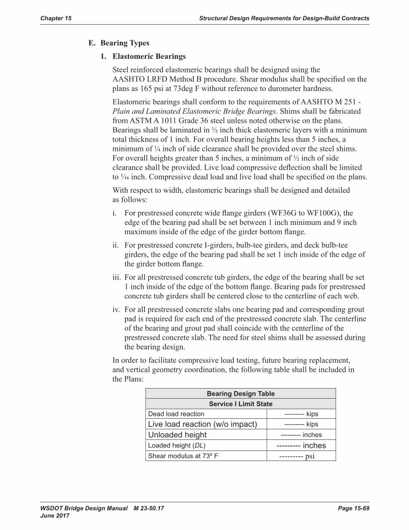
Chapter 15 Structural Design Requirements for Design-Build Contracts
WSDOT Bridge Design Manual M 23-50.17 Page 15-69 June 2017
E. BearingTypes
1. ElastomericBearings
SteelreinforcedelastomericbearingsshallbedesignedusingtheAASHTOLRFDMethodBprocedure.Shearmodulusshallbespecifiedontheplansas165psiat73degFwithoutreferencetodurometerhardness.
ElastomericbearingsshallconformtotherequirementsofAASHTOM251-Plain and Laminated Elastomeric Bridge Bearings.ShimsshallbefabricatedfromASTMA1011Grade36steelunlessnotedotherwiseontheplans.Bearingsshallbelaminatedin½inchthickelastomericlayerswithaminimumtotalthicknessof1inch.Foroverallbearingheightslessthan5inches,aminimumof¼inchofsideclearanceshallbeprovidedoverthesteelshims.Foroverallheightsgreaterthan5inches,aminimumof½inchofsideclearanceshallbeprovided.Liveloadcompressivedeflectionshallbelimitedto1/16inch.Compressivedeadloadandliveloadshallbespecifiedontheplans.
Withrespecttowidth,elastomericbearingsshallbedesignedanddetailedasfollows:
i. Forprestressedconcretewideflangegirders(WF36GtoWF100G),theedgeofthebearingpadshallbesetbetween1inchminimumand9inchmaximuminsideoftheedgeofthegirderbottomflange.
ii. ForprestressedconcreteI-girders,bulb-teegirders,anddeckbulb-teegirders,theedgeofthebearingpadshallbeset1inchinsideoftheedgeofthegirderbottomflange.
iii. Forallprestressedconcretetubgirders,theedgeofthebearingshallbeset1inchinsideoftheedgeofthebottomflange.Bearingpadsforprestressedconcretetubgirdersshallbecenteredclosetothecenterlineofeachweb.
iv. Forallprestressedconcreteslabsonebearingpadandcorrespondinggroutpadisrequiredforeachendoftheprestressedconcreteslab.Thecenterlineofthebearingandgroutpadshallcoincidewiththecenterlineoftheprestressedconcreteslab.Theneedforsteelshimsshallbeassessedduringthebearingdesign.
Inordertofacilitatecompressiveloadtesting,futurebearingreplacement,andverticalgeometrycoordination,thefollowingtableshallbeincludedinthePlans:
Bearing Design TableServiceILimitState
Dead load reaction --------- kipsLive load reaction (w/o impact) --------- kipsUnloaded height --------- inchesLoaded height (DL) --------- inchesShear modulus at 73º F --------- psi
Structural Design Requirements for Design-Build Contracts Chapter 15
Page 15-70 WSDOT Bridge Design Manual M 23-50.17 June 2017
Intheconstructionofprecastprestressedconcretegirderandsteelgirderbridges,elastomericbearingsneednotbeoffsettoaccountfortemperaturevariationduringerectionofthegirders.Girdersmaybesetatopelastomericbearingsattemperaturesotherthanthemeanofthetemperaturerange.Thisshallbestatisticallyreconciledbyassumingamaximumthermalmovementineitherdirectionof:
Δtemp=0.75∙α∙L∙(TMaxDesign–TMinDesign)
whereTMaxDesignisthemaximumanticipatedbridgedeckaveragetemperatureandTMinDesignistheminimumanticipatedbridgedeckaveragetemperatureduringthelifeofthebridge.
Forprecastprestressedconcretegirderbridges,themaximumthermalmovement,Δtemp,shallbeaddedtoshrinkageandlong-termcreepmovementstodeterminetotalbearingheightrequired.Theshrinkagemovementforthisbridgetypeshallbehalfthatcalculatedforacast-in-placeconcretebridge.
2. Fabric Pad Sliding Bearings
Fabricpadslidingbearingsincorporatefabricpadswithapolytetrafluoroethylene(PTFE)-stainlesssteelslidinginterfacetopermitlargetranslationalmovements.
UnfilledPTFEshallbeusedforfabricpadslidingbearings.
UnfilledPTFEshallberecessedhalfitsdepthintoasteelbackingplate,whichshallbebondedtothetopofafabricpad.Thestainlesssteelsheetshallbesealweldedtoasteelsoleplateattachedtothesuperstructure.
a. Fabric Pad Design
Maximumserviceloadaveragebearingpressureforfabricpadbearingdesignshallbe1,200psi.Maximumserviceloadedgebearingpressureforfabricpadbearingdesignshallbe2,000psi.
b. PTFE – Stainless Steel Sliding Surface Design
PTFEshallbeatleast3/16inchthickandrecessed3/32inchintoaminimum½inchthicksteelplatethatisbondedtothetopofthefabricpad.
StainlesssteelsheetshallbefinishedtoaNo.8(Mirror)finishandshallbesealweldedtothesoleplate.
3. Pin Bearings
Steelpinbearingsmaybeusedtosupportheavyreactionswithmoderatetohighlevelsofrotationaboutasinglepredeterminedaxis.
4. RockerandRollerTypeBearings
Rockerbearingsandsteelrollerbearingsarenotallowedfornewbridges.
Chapter 15 Structural Design Requirements for Design-Build Contracts
WSDOT Bridge Design Manual M 23-50.17 Page 15-71 June 2017
5. SphericalBearings
WovenPTFEshallbeusedonthecurvedsurfacesofsphericalbearings.Whensphericalbearingsaredetailedtoaccommodatetranslationalmovement,wovenPTFEshallbeusedontheflatslidingsurfacealso.
Sphericalbearingsshallbedetailedwiththeconcavesurfaceorienteddownward.Structuralanalysisoftheoverallstructureshallrecognizethecenterofrotationofthebearingnotbeingcoincidentwiththeneutralaxisofthegirderabove.
Thecontractdrawingsshallshowthediameterandheightofthesphericalbearinginadditiontoalldead,live,andseismicloadings.Soleplateconnections,baseplate,anchorbolts,andanyappurtenancesforhorizontalforcetransfershallbedetailedontheplans.ThesphericalbearingmanufacturershallsubmitshopdrawingsanddetailedstructuraldesigncalculationsofsphericalbearingcomponentsforreviewandcommentbyWSDOT.
6. Disc Bearings
Discbearingscomposedofanannularshapedpolyetherurethanediskwithasteelshear-resistingpininthecentermaybeused.AflatPTFE-stainlesssteelsurfacemaybeincorporatedintothebearingtoalsoprovidetranslationalmovementcapability.
7. SeismicIsolationBearings
Seismicisolationbearingsmaybeused,subjecttotherestrictionsoutlinedinSections4.2.2 and9.3.3.
F. Miscellaneous Details
1. TemporarySupportbeforeGroutingMasonryPlate
ThemasonryplateofanHLMRbearingshallbesupportedonagroutpadthatisinstalledafterthebearingandsuperstructuregirdersabovehavebeenerected.ThissequenceallowstheContractortolevelandslightlyadjustthehorizontallocationofthebearingbeforeimmobilizingit.Twomethodsfortemporarilysupportingthemasonryplateareacceptable:
a. ShimPacks
Multiplestacksofsteelshimplatesmaybeplacedatoptheconcretesurfacetotemporarilysupporttheweightofthegirdersontheirbearingsbeforegrouting.
b. Two-stepGroutingwithCastSleeves
Atwo-stepgroutingprocedurewithcast-in-placevoidedcoresmaybeusedforsmallerHLMRsnotgenerallysubjectedtouplift.Steelstudsareweldedtotheundersideofthemasonryplatetocoincidewiththevoidedcores.Withtemporaryshimsinstalledbetweenthetopoftheconcretesurfaceandtheundersideofthemasonryplate,thevoidedcoresarefullygrouted.Oncethefirststagegrouthasattainedstrength,theshimsareremoved,themasonryplateisdammed,andgroutisplacedbetweenthetopoftheconcretesurfaceandtheundersideofthemasonryplate.
Structural Design Requirements for Design-Build Contracts Chapter 15
Page 15-72 WSDOT Bridge Design Manual M 23-50.17 June 2017
2. Anchor Bolts
Anchorboltsshallbedesignedtoresistallhorizontalshearforcesanddirecttensionforceduetouplift.
AnchorboltsshallbeASTMA449wherestrengthsequaltoASTMA325arerequiredandASTMA354,GradeBD,wherestrengthsequaltoASTMA490arerequired.AnchorboltsshallbeASTMF1554boltswithsupplementalCharpytestrequirementsinapplicationsinwhichtheboltsaresubjecttoseismicloading.
G. ContractDrawingRepresentation
Highloadmulti-rotationalbearingsshallbedepictedschematicallyinthecontractdrawings.Eachbearingmanufacturerhasuniquefabricatingmethodsandproceduresthatallowittofabricateabearingmosteconomically.Depictingthebearingsschematicallywithloadsandgeometricrequirementsprovideseachmanufacturertheflexibilitytoinnovativelyachieveoptimaleconomy.
H. ShopDrawingReview
High-loadmulti-rotationalbearingsshallbedesigned,tested,fabricated,QA\QCinspected,andinstalledinaccordancewiththeSpecialProvisionsintheRFPAppendix,includingsubmittalofdesigncalculationsandshopdrawings.
I. BearingReplacementConsiderations
Bearingsshallbedesignedanddetailedtopermitthereplacementofallelementssubjecttowear.Superstructureandsubstructureelementsshallbedesignedanddetailedtoaccommodateliftingofthesuperstructureusinghydraulicjackstofacilitatebearingelementreplacement.
Forbearingreplacements,theDesign-Buildershallshowanticipatedliftingloadsonthecontractdrawings.Limitationsonliftheightshallalsobespecified.Considerationshallbegiventoliftheightasitrelatestoadjacentexpansionjointselementsandadjoiningsectionsofrailing.Restrictionsondifferentialliftheightbetweenmultiplejacksshallbespecifiedtominimizestressesinducedinadjacentstructuralelements.
Jacksshallbesizedfor200percentofthecalculatedliftingload.
WSDOT Bridge Design Manual M 23-50.17 Page 15-73 June 2017
15.10 Signs, Barriers, Bridge Approach Slabs, and Utilities15.10.1 Sign and Luminaire Supports
A. Loads
1. General
ThereferenceusedindevelopingthefollowingofficecriteriaistheAASHTO“LRFD for Structural Supports for Highway Signs, Luminaires, and Traffic Signals,” First Edition Dated 2015, and shall be the basis for analysis and design.
2. DesignLife(Section11.5,AASHTO2015)
a. AnInfinitelifefatiguedesignwillbeusedforluminairesupports,overheadsignstructures,andtrafficsignalstructures.ThenumberofcyclesastructuremustwithstandwillbebasedontheADTTofa75yeardesignlifewitheachtruckinducingonecycleinaccordancewithAASHTOLRFDStandard Specifications for Structural Supports for Highway Signs, Luminaires, and Traffic Signals First Edition,dated2015 includinginterims.
b. Roadsidesignstructureswillusea10yeardesignlife.
3. Dead Loads
Sign(includingpanelandwindbeams,doesnot includevert.bracing) 3.25lbs/ft2 Luminaire(effectiveprojectedareaofhead=3.3sqfeet) 60lbs/each FluorescentLighting 3.0lbs/ft StandardSignalHead 60lbs/each MercuryVaporLighting 6.0lbs/ft SignBrackets Calc. StructuralMembers Calc. 5footwidemaintenancewalkway (includingsignmountingbracketsandhandrail) 160lbs SignalHeadw/3lenses (effectiveprojectedareawithbackingplate=9.2sqfeet) 60lbs/each
4. Live Load
Aliveloadconsistingofasingleloadof500lbdistributedover2.0feettransverselytothemembershallbeusedfordesigningmembersforwalkwaysandplatforms.Theloadshallbeappliedatthemostcriticallocationwhereaworkerorequipmentcouldbeplaced,see2015AASHTOSpecifications Section3.6.
5. WindLoads
A3secondgustwindspeedshallbeusedintheAASHTOwindpressureequation.The3secondwindgustmapinAASHTOisbasedonthewindmapinANSI/ASCE7-10.
Structural Design Requirements for Design-Build Contracts Chapter 15
Page 15-74 WSDOT Bridge Design Manual M 23-50.17 June 2017
Thebasicwindspeedof115mphshallbeusedincomputingdesignwindpressureusingEquation3.8.1-1ofAASHTOSection3.8.1. Thisisbasedonthehighriskcategorywithameanrecurrenceintendedof1700yearsperAASHTOTable3.8-1.
TheAlternateMethodofWindPressuresgiveninAppendixCoftheAASHTO2009Specificationsshallnotbeused.
6. Fatigue Design
FatiguedesignshallconformtoAASHTOSection11withtheexceptionoftubeshape.AASHTOdoesnotprovidefatiguecalculationsfortubeshapeswithlessthan8sides.ThereforeincalculatingtheConstantAmplitudeFatigueThreshold,DT(Table11.9.3.1-2,AASHTO2015)wastakentobethelargerouterflattoflatdistanceoftherectangulartube.FatigueCategoriesarelistedinTable11.6-1.OverheadCantileverandBridgeSign&signalstructures,highmastluminaires(HMLT),poles,andbridgemountedsignbracketsshallconformtothefollowingfatiguecategories.
FatigueCategoryI:Overheadcantileversignstructures(maximumspanof30feetandnoVMSinstallation),overheadsignbridgestructures,highlevel(highmast)lightingpoles80feetortallerinheight,bridge-mountedsignbrackets,andallsignalbridges.Gantryorpolestructuresusedtosupportsensitiveelectronicequipment(tolling,weigh-in-motion,transmitter/receiver antennas,transponders,etc.)shallbedesignedforFatigueCategoryI, andshallalsomeetanydeflectionlimitationsimposedbytheelectronicequipmentmanufacturers.
FatigueCategoryII:ForstructuresnotexplicitlyfallingintoCategoryIorIII.
FatigueCategoryIII:Lightingpoles50feetorlessinheightwithrectangular,squareornon-taperedroundcrosssections,andoverheadcantilevertrafficsignalsatintersections(maximumcantileverlength65feet).
Signbridges,cantileversignstructures,signalbridges,andoverheadcantilevertrafficsignalsmountedonbridgesshallbeeitherattachedtosubstructureelements(e.g.,crossbeamextensions)ortothebridgesuperstructureatpierlocations.Mountingthesefeaturestobridgesasdescribedabovewillhelptoavoidresonanceconcernsbetweenthebridgestructureandthesigningorsignalstructure.
The“XYZ”limitationshowninTable10.1.4-2shallbemetforMonotubeCantilevers.The“XYZ”limitationconsistsoftheproductofthesignarea(XY)andthearmfromthecenterlineofthepoststothecenterlineofthesign(Z).SeeAppendix10.1-A2-1fordetails.
7. Ice and Snow Loads
A3psficeloadmaybeappliedaroundallthesurfacesofstructuralsupports,horizontalmembers,andluminaires,butappliedtoonlyonefaceofsignpanels(Section3.7,AASHTO2015).
Walk-throughVMSshallnotbeinstalledinareaswhereappreciablesnowloadsmayaccumulateontopofthesign,unlesspositivestepsaretakentopreventsnowbuild-up.
Chapter 15 Structural Design Requirements for Design-Build Contracts
WSDOT Bridge Design Manual M 23-50.17 Page 15-75 June 2017
8. GroupLoadCombinations
Sign,luminaire,andsignalsupportstructuresaredesignedusingtheloadfactorsfromTable10.1.1-1,AASHTO2015.
B. Bridge Mounted Signs
1. Vertical Clearance
AllnewsignsmountedonbridgestructuresshallbepositionedsuchthatthebottomofthesignorlightingbracketdoesnotextendbelowthebottomofthebridgeasshowninFigure10.1.2-1.
Bridgemountedsignbracketsshallbedesignedtoaccountfortheweightofaddedlights,andforthewindeffectsonthelightstoensurebracketadequacyiflightingisattachedinthefuture.
2. Geometrics
a. Signsshallbeinstalledatapproximaterightanglestoapproachingmotorists.Forstructuresaboveatangentsectionofroadway,signsshallbedesignedtoprovideasignskewwithin5degreesfromperpendiculartothelowerroadway(seeFigure10.1.2-2).
b. Forstructureslocatedonorjustbeyondahorizontalcurveofthelowerroadway,signsshallbedesignedtoprovideasignchordskewwithin5degreesfromperpendiculartothechord-pointdeterminedbytheapproachspeed(seeFigure10.1.2-3).
c. Thetopofthesignshallbelevel.
3. Aesthetics
a. Thesupportstructureshallnotextendbeyondthelimitsofthesign.
b. Thesignsupportshallbedetailedinsuchamannerthatwillpermitthesignandlightingbrackettobeinstalledlevel.
4. SignPlacement
a. Signsshallneverbeplacedunderbridgedeckoverhangsordirectlyunderthedriplineofthebridge.
b. Aminimumof2inchesofclearanceshallbeprovidedbetweenbacksideofthesignsupportandedgeofthebridge,seeFigure10.1.2-5.
5. Installation
a. Resinbondedanchorsorcast-in-placeASTMF593Group1,ConditionAanchorrodsshallbeusedtoinstallthesignbracketsonthestructure.Sizeandminimuminstallationdepthshallbegivenintheplansorspecifications.Theresinbondedanchorsshallbeinstallednormaltotheconcretesurface,andshallnotbecoredrilled.Resinbondedanchorsshallnotbeplacedthroughthewebsorflangesofprestressedorpost-tensionedgirders.Resinbondedanchorsshallnotbeusedatoverheadlocationsotherthanwithhorizontalhole/anchoralignment.
b. Bridgemountedsignstructuresshallnotbeplacedonbridgeswithsteelsuperstructures.
Structural Design Requirements for Design-Build Contracts Chapter 15
Page 15-76 WSDOT Bridge Design Manual M 23-50.17 June 2017
6. Installing/ReplacingSignPanelsonExistingBridgeMountedSign Brackets
Wheninstallinganewsignpanelonanexistingbridgemountedsignbracket,theinstallationshallconformtothefollowing.
a. AllhardwareshallbereplacedinaccordancewithStandard Specifications Section9-28.11.
b. Theareaofthenewsignpanelshallnotexceedtheareaoftheoriginallydesignedsignpanel.
c. TheWSDOTinspectionreportforthebridgemountedsignbracketshallbereviewedtoensuretheassemblyisingoodcondition.Ifthereisnoinspectionreport,thenaninspectionshallbeperformedtoestablishthecurrentconditionoftheassembly.
7. MaterialSpecifications
a. MaterialspecificationsshallbeasshowninBridgeStandardDrawings 10.1-A6-1.
b. Allnon-stainlesssteelpartsshallbegalvanizedinaccordancewithAASHTOM111afterfabrication.BoltsandhardwareshallbegalvanizedinaccordancewithAASHTOM232.
C. Monotube Sign Structures Mounted on Bridges
1. Design Loads
DesignloadsforthesupportsoftheSignBridgesshallbecalculatedbasedonassuminga12footdeepsignovertheentireroadwaywidth,underthesignbridge,regardlessofthesignareainitiallyplacedonthesignbridge.ForCantileverdesignloads,guidelinesspecifiedinSection10.1.1shallbefollowed.ThedesignloadsshallfollowthesamecriteriaasdescribedinSection10.1.1.Loadsfromthesignbridgeshallbeincludedinthedesignofthesupportingbridge.
Incaseswhereasignstructureismountedonabridge,thesignstructure,fromtheanchorboltgroupandabove,shallbedesignedtoAASHTOStandard Specifications for Structural Supports for Highway Signs, Luminaires, and Traffic Signals,FirstEdition,dated2015,includinginterims.TheconcretearoundtheanchorboltgroupandtheconnectingelementstothebridgestructureshallbedesignedtothespecificationsinthismanualandAASHTOLRFD.LoadsfromthesignstructuredesigncodeshallbetakenasunfactoredloadsforuseinAASHTOLRFD Bridge Design Specifications.
2. Vertical Clearance
VerticalclearanceforMonotubeSignStructuresshallbe20′-0″minimumfromthebottomofthelowestsigntothehighestpointinthetraveledlanes.SeeBridgeStandardDrawings10.1-A1-1,10.1A2-1,and10.1-A3-1forsamplelocationsofMinimumVerticalClearances.
Chapter 15 Structural Design Requirements for Design-Build Contracts
WSDOT Bridge Design Manual M 23-50.17 Page 15-77 June 2017
3. Geometrics
Signstructuresshallbeplacedatapproximaterightanglestoapproachingmotorists.DimensionsanddetailsofsignstructuresareshownintheWSDOTStandardPlansG-60.10,G-60.20,G-60.30,G-70.10,G-70.20,G-70.30andBridgeStandardDrawings 10.1-A1-1,10.1-A1-2,and10.1-A1-3and10.1-A1-1,10.1-A1-2,and10.1-A1-3.Whenmaintenancewalkwaysareincluded,refertoStandardPlansG-95.10,G-95.20,andG-95.30.
D. Monotube Sign Structures
1. Sign Bridge Conventional Design
Table10.1.4-1providestheconventionalstructuraldesigninformationtobeusedforaSignBridgeLayout,BridgeStandardDrawings 10.1-A1-1;alongwiththeStructuralDetailsheets,whichareBridgeStandardDrawings 10.1-A1-1and10.1-A1-3;andGeneralNotes,BridgeStandardDrawings 10.1-A5-1; andMiscellaneousDetails,Appendix10.1-A5-2.Signbridgespanlengthsshallnotexceed180-feet.
2. Cantilever Conventional Design
Table10.1.4-2providestheconventionalstructuraldesigninformationtobeusedforaCantileverLayout,BridgeStandardDrawings 10.1-A2-1;alongwiththeStructuralDetailsheets,whichareBridgeStandardDrawings 10.1-A2-2and10.1-A2-3;andGeneralNotes,Appendix10.1-A5-1;andMiscellaneousDetails,Appendix10.1-A5-2. Cantileverarmlengthsshallnotexceed35-feet.CantileversignstructuresshallnotbeusedtosupportVMSsigns.
3. Balanced Cantilever Conventional Design
BridgeStandardDrawings 10.1-A3-1;alongwiththeStructuralDetailsheets,BridgeStandardDrawings 10.1-A3-2and10.1-A3-3,GeneralNotes,BridgeStandardDrawings 10.1-A5-1;andMiscellaneousDetails,Appendix10.1-A5-2 providestheconventionalstructuraldesigninformationtobeusedforaBalancedCantileverLayout,BalancedCantileversaretypicallyforVMSsignapplicationsandshallhavethesigndeadloadbalancedwithamaximumdifferenceofone-thirdtotwo-thirdsdistribution.
4. Monotube Sheet Guidelines
ThefollowingguidelinesapplywhenusingtheMonotubeSignStructureBridgeStandardDrawings 10.1-A1-1,10.1-A1-2,and10.1-A1-3;10.1-A2-1,10.1-A2-2,and10.1-A2-3;10.1-A3-1,10.1-A3-2,and10.1-A3-3;10.1A4-1,10.1A4-2,and10.1A4-3;and10.1-A5-1,10.1-A5-2,and10.1-A5-3.
Eachsignstructureshallbedetailedtospecify:
i. SignstructurebaseElevation,Station,andNumber.
ii. TypeofFoundation1,2,or3shallbeusedfortheMonotubeSignStructures,unlessanon-conventionaldesignisrequired.TheaverageLateralBearingPressureforeachfoundationshallbenotedontheFoundationsheet(s).
iii. Ifapplicable,labeltheElevationView“LookingBackonStationing”.
Structural Design Requirements for Design-Build Contracts Chapter 15
Page 15-78 WSDOT Bridge Design Manual M 23-50.17 June 2017
5. VMSInstallation
a. VMSunitsshallnotbeinstalledonunbalancedcantileverstructures.
b. VMSinstallationonSignBridgestructuresdesignedinaccordancewithAASHTO2015shallbeinstalledinaccordancewiththefollowing:
i. Onspans120feetandgreateruptotwoVMSunitsmaybeinstalledwithamaximumweightof4,000lbs.each.MaintenancewalkwaysmaybeinstalledbetweenVMSunits,butmaynotexceed160lbs/ft,orexceed50percentofthestructurespanlength.
ii. Onspanslessthan120feetuptothreeVMSunitsmaybeinstalledwithamaximumweightof4,000lbs.each.MaintenancewalkwaysmaybeinstalledbetweenVMSunits,butmaynotexceed160lbs/ft.
c. ThenumberofVMSinstalledonSignBridgestructuresdesignedpriortoAASHTO2015shallbereducedbyoneasdefinedinD.2-aandb.
E. Foundations
1. MonotubeSignStructureFoundationTypes
Thefoundationtypetobeusedshallbebasedonthegeotechnicalinvestigationperformedandgeotechnicalreportcompletedbythegeotechnicalengineerofrecord.Standardfoundationdesignsforstandardplantruss-typesignstructuresareprovidedinStandardPlansG-60.20, G-60.30,G-70.20,andG-70.30. MonotubesignstructurefoundationsareBridgeDesignOfficeconventionaldesignsandshallbeasdescribedinthefollowingparagraphs:
a. FoundationType1,isthepreferredfoundationtype.AfoundationType1consistsofadrilledshaftwithitsshaftcap.ThedesignoftheshaftdepthsshownintheSignBridgeStandardDrawingsarebasedonalateralbearingpressureof2,500psf.ThedesignershallchecktheseshaftdepthsusingLRFDmethodology.ForType1foundationdetailsandshaftdepthsseeSignBridgeStandardDrawings10.1-A4-1and10.1-A4-2.TheGeotechnicalreportforFoundationType1shouldincludethesoilfrictionangle,soilunitweight,allowablebearingpressureandtemporarycasingifrequired.TemporarycasingshallbeproperlydetailedinallFoundationType1sheetsiftheGeotechnicalEngineerrequiresthem.
b. FoundationType2isdesignedforalateralbearingpressureof2,500psf.SeeBridgeStandardDrawing10.1-A4-3forBridgeDesignOfficeconventionalFoundationType2designinformation.ThedesignershallchecktheseshaftdepthsusingLRFDmethodology.
c. FoundationType3replacesthefoundationType2forpoorsoilconditionswherethelateralbearingpressureisbetween2,500psfand1,500psf.SeeBridgeStandardDrawing10.1-A4-3forBridgeDesignOfficeconventionalFoundationType3designinformation.ThedesignershallchecktheseshaftdepthsusingLRFDmethodology.
d. BarrierShapeFoundationsarefoundationsthatincludeabarriershapecaponthetopportionofFoundationTypes1,2,and3.FoundationdetailsshallbemodifiedtoincludeBarrierShapeCapdetails.SeeBridgeStandardDrawing10.1-A5-1detailsasingleslopebarrier.
Chapter 15 Structural Design Requirements for Design-Build Contracts
WSDOT Bridge Design Manual M 23-50.17 Page 15-79 June 2017
2. Luminaire,SignalStandard,andCameraPoleFoundationTypes
LuminairefoundationoptionsareshownonWSDOTStandardPlanJ-28.30. SignalStandardandCameraPolefoundationoptionsareprovidedonWSDOTStandardPlansJ-26.10andJ-29.10respectively.
3. Foundation Design
Shafttypefoundationsconstructedinsoilforsignbridges,cantileversignstructures,luminaires,signalstandardsandstrainpolesshallbedesignedinaccordancewiththecurrenteditionoftheAASHTOLRFD Standard Specifications For Highway Signs, Luminaires, and Traffic Signals;Section13.16;DrilledShafts.
NoprovisionsforfoundationtorsionalcapacityareprovidedinSection10.13oftheAASHTOStandard Specifications for Highway Signs, Luminaires, and Traffic Signals.Thefollowingapproachcanbeusedtocalculatetorsionalcapacityofsignstructure,luminaire,andsignalstandardfoundations:
TorsionalCapacity,φTn,φTn=F*tanφD
Where:F =Totalforcenormaltoshaftsurface(kip)
D =Diameterofshaft(feet)φ =Soiltofoundationcontactfrictionangle(degree),usesmallestfor
variablesoils
a. Monotube Sign Bridge and Cantilever Sign Structures Foundation Type1Design
Thestandardembedmentdepth“Z”,showninthetableonMonotubeSignStructure BridgeStandardDrawing10.1-A4-1,shallbeusedasaminimumembedmentdepthandshallbeincreasediftheshaftisplacedonaslopedsurface,oriftheallowablelateralbearingpressuresarereducedfromthestandard2500psf.Thestandarddepthassumedthatthetop4feetoftheC.I.P.capisnotincludedinthelateralresistance(i.e.,shaftdepth“D”inthecodementionedabove),butisincludedintheoverturninglengthofthesignstructure.Thesign structureshaftfoundationGSPsunderSection8-21intheRFPAppendixshallapplyforallFoundationType1shafts.
b. MonotubeSignStructuresFoundationType2and3
ThesefoundationdesignsareBridgeDesignOfficeconventionandshallnotbeadjusted.
c. Monotube Sign Structures Non-Conventional Design Foundations
Thegeotechnicalengineerofrecordshallidentifyanylocationswherethefoundationtypes(1,2,or3)willnotwork.Attheselocations,thedesignforcesarecalculated,usingtheAASHTOLRFD Standard Specifications for Structural Supports for Highway Signs, Luminaires, and traffic Signals,andappliedatthebottomofthestructurebaseplate.Theseforcesarethenconsideredserviceloadsandthenon-conventionaldesignfoundationisdesignedwiththeappropriateService,Strength,and
Structural Design Requirements for Design-Build Contracts Chapter 15
Page 15-80 WSDOT Bridge Design Manual M 23-50.17 June 2017
ExtremeLoadCombinationLimitStatesandcurrentdesignpracticesoftheAASHTOLRFDandthismanual.TheanchorrodarrayshallbeusedfromTables10.1.4-1and10.1.4-2andshallbelongenoughtodeveloptherodsintotheconfinedconcretecoreofthefoundation.Therodlengthandthereinforcementforconcreteconfinement,showninthetopfourfeetoftheFoundationType1,shallbeusedasaminimum.
d. Signal Foundation Design
ThetrafficsignalstandardGSPsintheRFPSection8-20shallapplyforfoundationsinsubstandardsoils.
F. Truss Sign Bridges: Foundation Sheet Design Guidelines
IfaTrusssignstructureisused,refertoWSDOTStandard Plansforfoundationdetails.TherearefouritemsthatshouldbeaddressedwhenusingtheWSDOTStandard Plans,whichareoutlinedbelow.
a. Determineconduitneeds.Ifnoneexist,deleteallreferencestoconduit.Ifconduitisrequired,verifyastosizeandquantity.
b. Showsignbridgebaseelevation,number,dimensionandstation.
c. TheconcretebarriertransitionsectionshallbeinaccordancewiththeStandard Plans.
d. ThequantitiesshallbebasedontheStandard Plansdetailsasneeded.
15.10.2 BridgeTrafficBarriersA. General Guidelines and Policy
ThedesigncriteriafortrafficbarriersonstructuresshallbeinaccordancewithChapter13oftheAASHTOLRFDwiththefollowingsupplementalguidelines.
WSDOTstandard42-inchhighSingleSlopeconcretebarriershallbeusedforbarriersonnewbridgesandbridgeapproachslabs.WSDOTstandard34-inchor42-inchSingleSlopeconcretebarriershallbeusedforbarriersonexistingbridges,bridgerehabilitationprojects,andretainingwalls,includinggeosyntheticwallsandstructuralearthwalls.
Useof32-inchor42-inchF-Shapeconcretebarriershallbelimitedforcontinuityoffstructureorwithinacorridor.UseofPedestrianconcretebarriershallbelimitedforlocationswithsidewalk.Useof42-inchor54-inchcombinationbarriers(32-inchor34-inchconcretebarrierincreasedinheightbymetalrailing)maybeusedonlyifallowedbytheRFPCriteria.SeeChapter10AppendixforavailableWSDOTstandardbridgebarrierdesigns.
BarriersshallbedesignedforminimumTestLevel4(TL-4)designcriteriaregardlessofthebarrierheight.TheTestLevelshallbespecifiedinthePlans.
ATestLevel5(TL-5)barriershallbeusedonnewstructuresfor“T”intersections,forbarriersonstructureswitharadiusofcurvaturelessthan500feet(TL-4isacceptableforbarrierontheinsideofthecurve),locationswithAverageDailyTruckTraffic(ADTT)greaterthan10percent,andlocationswithapproachspeedsat50mphorgreater(e.g.freewayoff-ramps).
SeeAASHTOLRFDChapter13foradditionalTestLevelselectioncriteria.
Chapter 15 Structural Design Requirements for Design-Build Contracts
WSDOT Bridge Design Manual M 23-50.17 Page 15-81 June 2017
B. Design Criteria
1. StructuralCapacity
AASHTOLRFDAppendixA13shallbeusedtodesignbarriersandtheirsupportingelements(i.e.deck).
ConcretebarriersshallbedesignedusingyieldlineanalysisasdescribedinAASHTOLRFDSectionA13.3.1.
DeckoverhangssupportingconcretebarriersshallbedesignedinaccordancewithAASHTOLRFDSectionA13.4asmodifiedbySection10.2.4.A.
2. Geometry
Thetrafficfacegeometryispartofthecrashtestandshallnotbemodified.
Concreteclearcovershallmeetminimumconcretecoverrequirementsandshallbeincreasedtoaccommodaterusticationgroovesorpatternsforarchitecturalreasons.Concretecovershallbeincreasedto2½″fortrafficfaceofbarrierforslipformmethodofconstruction.
The3″toedimensionoftheF-ShapebarriershallbeincreasedtoaccommodateHMAoverlaystoamaximumof6″.
Fordesigninganddetailingbridgedeckswithasuperelevationof8percentorless,theexteriorbarrierand/orthemedianbarriershallbeorientedperpendiculartothebridgedeck.Bridgedeckswithasuperelevationofmorethan8percent,thebarrieronthelowsideofthebridgeand/ormedianbarriershallbeorientedperpendiculartoan8percentsuperelevatedbridgedeck,andthebarrieronthehighsideofthebridgeshallbeorientedperpendiculartothebridgedeck.
3. MiscellaneousDesignInformation
SteelreinforcementbarsS1andS2orS3andS4andW1andW2(orequivalentbars)fromChapter10AppendixbarrierstandarddrawingsshallbeincludedintheBarList.
SteelreinforcementbarsS1,S3,AS1,AS3,andW1(orequivalentbars)fromChapter10Appendixbarrierstandarddrawingsshallbeepoxycoated.
AnymodificationstoChapter10AppendixbarrierstandarddrawingsortoWSDOTStandard Plans shallnotalterorcompromisethestructuralintegrityand/orcrashtestperformanceofbarrier.ModificationsshallbesubmittedforreviewandacceptancebyWSDOTforconcurrencewithdesignpolicies.
15.10.3 At Grade Concrete BarriersDifferentialgradeconcretebarrierswithagradedifferencegreaterthan4′-0″shallbedesignedasreinforcedconcreteretainingwallswithatrafficbarrieratthetopandabarriershapeatthecutface.
Differentialgradeconcretebarrierswithagradedifference4′-0″orlessshallbedesignedinaccordancetoAASHTOLRFDbarrierloadingwiththefollowingguidelines.
Structural Design Requirements for Design-Build Contracts Chapter 15
Page 15-82 WSDOT Bridge Design Manual M 23-50.17 June 2017
Fulldepthexpansionjointswithsheardowelsatthetopshallbeprovidedat120′maximumspacing.
Barriershallbecontinuousorhaveshearconnectionsbetweenbarriersectionsifprecast.
A. DifferentialGradeConcreteBarrierDesignCriteria
1. StructuralCapacity
ThestructuralcapacityofthedifferentialgradeconcretebarriershallbedesignedfortherequiredTestLevel(TL)vehicleimpactdesignforcesinaccordancewithAASHTOLRFDChapters5and13.
Anysectionalongthedifferentialgradeconcretebarriershallnotfailinshear,bending,ortorsionwhenthebarrierissubjectedtotheTLimpactforces.
ThetorsioncapacityofthedifferentialgradeconcretebarriershallbeequaltoorgreaterthanthetrafficbarriermomentgeneratedbytheTLimpactforcesappliedtothetopofthebarrier.
2. Global Stability
GlobalstabilityshallbeinaccordancewithSection10.3.1.A.
3. Geometry
Thetopofthedifferentialgradeconcretebarriershallhaveaminimumwidthof6″withaminimum6″cleardistancetoeachsideofluminaireorsignpoleifmountedontopofthedifferentialgradeconcretetrafficbarrier.ThetransitionflarerateshallfollowtheDesign Manual M22-01.
Barrierbottomshallbeembeddedaminimum6″belowroadway.Roadwaysubgradeandballastshallbeextendedbelowwholewidthofdifferentialgradeconcretebarrier.
B. TrafficBarrierMomentSlabDesignCriteria
1. StructuralCapacity
ThestructuralcapacityofthetrafficbarriermomentslabshallbedesignedfortherequiredTLimpactforcesinaccordancewithAASHTOLRFDChapters5and13.
Anysectionalongthemomentslabshallnotfailinshear,bending,ortorsionwhenthebarrierissubjectedtotheTLimpactforces.
Themomentslabreinforcementshallbedesignedtoresistforcesdevelopedatthebaseofthebarrier.MomentslabsupportingconcretebarriershallbedesignedinaccordancetoDeckOverhangDesigninaccordancewithAASHTOLRFDSectionA13.4asmodifiedbySection10.2.4.A.
ThetorsioncapacityofthemomentslabshallbeequaltoorgreaterthanthetrafficbarriermomentgeneratedbytheTLimpactforces.
2. Global Stability
See Section10.3.2.B.2.
Chapter 15 Structural Design Requirements for Design-Build Contracts
WSDOT Bridge Design Manual M 23-50.17 Page 15-83 June 2017
3. Geometry
Momentslabsshallhaveaminimumwidthof4.0feetmeasuredfromthepointofrotationtotheheeloftheslabandaminimumaveragedepthof0.83feet.
4. SoilReinforcement
DesignofthesoilreinforcementshallbeinaccordancewiththeGeotechnical Design ManualChapter15.
5. WallPanel
ThewallpanelsshallbedesignedtoresistthedynamicpressuredistributionsasdefinedintheGeotechnical Design ManualChapter15.
Thewallpanelshallhavesufficientstructuralcapacitytoresistthemaximum design rupture load for the wall reinforcement designed in accordance with the Geotechnical Design ManualChapter15.
C. Precast Concrete Barrier
ConcretebarrierType2andType4shallbeusedinaccordancetoSection10.3.4.
15.10.4 BridgeTrafficBarrierRehabilitationA. General Guidelines and Policy
WhenidentifiedintheRFP,deficientrailsshallbeimprovedorreplacedwithinthelimitsofroadwayresurfacingprojectsinaccordancetoSection10.4.
RetrofitshallbeanapprovedcrashtestedrailsystemorshallbedesignedtothestrengthrequirementssetforthbySection2ofAASHTOStandard Specifications for Highway Bridges,17thedition.
See Section10.4.4andWSDOT Design Manualforreplacementcriteria.
See Section10.4.5and10.4.6foravailablebridgerailretrofitandbridgerailreplacementdesigns.
B. Design Criteria
1. StructuralCapacity
Astrengthandgeometricreviewshallberequiredforallbridgerailrehabilitationprojects.TheAASHTOLFDloadof10kipsshallbeusedintheretrofitofexistingtrafficbarriersystemsconstructedpriortotheyear2000.
Ifthestrengthoftheexistingbridgerailandtheirsupportingelements(i.e.deck)areunabletoresista10kipbarrierimpactdesignloadorhasnotbeencrashtested,thenmodificationsorreplacementwillberequiredtoimproveitsredirectionalcharacteristicsandstrength.
IfthedesignofthebridgerehabilitationincludesotherbridgecomponentsthatwillbedesignedusingAASHTOLRFDthenthefollowingminimumequivalentExtremeEvent(CT)trafficbarrierloadingcanbeused:
Flexure=(1.3)*(1.67)*(10kip)/(0.9)=24.10kip
Shear=(1.3)*(1.67)*(10kip)/(0.85)=25.54kip
Structural Design Requirements for Design-Build Contracts Chapter 15
Page 15-84 WSDOT Bridge Design Manual M 23-50.17 June 2017
2. Geometry Standardthriebeamguardrailpostspacingis6′-3″exceptfortheSL-1
WeakPost,whichisat8′-4″.Postspacingcanbeincreasedupto10′-0″ifthethriebeamguardrailisnested(doubledup).
Guardrailshallbecontinuouswithoutgaps. DesignFguardrailendsectionsshallbeusedattheapproachandtrailing
endofthesegaps. StandardPlanthriebeamguardrailtransitionsshallbeusedateachcorner
ofthebridge. PlacementoftheretrofitsystemwillbedeterminedfromtheWSDOT
Design Manual.
15.10.5 Bridge RailingA. General Guidelines and Policy Pedestrianandbicycle/pedestrianrailingsshallbedesignedinaccordancewith
AASHTOLRFDChapter13withthefollowingsupplementalguidelines. Railingsshallbedesignedforvehicularimpactloadorbesuccessfullycrashtested
unlesslocationislowspeed,locationisoutsideofDesignClearZoneasdefinedinDesign Manual Chapter1600,orlocationhasminimalsafetyconsequencefromcollapseofrailing.
Minimumheightof54″shallbeprovidedforbicyclerailingsonstructures. FallProtectionrailingshallmeettherequirementsofWAC296-155. See Section10.5.2foravailablebridgerailingdesigns.
15.10.6 Bridge Approach SlabsBridgeapproachslabsarerequiredforallnewandwidenedbridges.
Bridgerunoffattheabutmentsshallbecarriedoffandcollectedatleast10feetbeyondthebridgeapproachslab.
A. BridgeApproachSlabDesignCriteria
Thestandardbridgeapproachslabdesignisbasedonthefollowingcriteria:
1. ThebridgeapproachslabisdesignedasaslabinaccordancewithAASHTOLRFD.(StrengthLimitState,IM=1.33,noskew).
2. Thesupportattheroadwayendisassumedtobeauniformsoilreactionwithabearinglengththatisapproximately⅓thelengthoftheapproachslab,or25′/3=8′.
3. TheEffectiveSpanLength(Seff),regardlessofapproachlength,isassumedtobe: 25′approach–8′=17′.
4. Longitudinalreinforcingbarsdonotrequiremodificationforskewedapproachesupto30degreesorforslablengthsgreaterthan25′.
5. Thebridgeapproachslabisdesignedwitha2″concretecovertothebottomreinforcing.
Chapter 15 Structural Design Requirements for Design-Build Contracts
WSDOT Bridge Design Manual M 23-50.17 Page 15-85 June 2017
B. BridgeApproachSlabDetailing
Theminimumdimensionfromthebridgeis25′.
AS1barsshallbeepoxycoated.Bendingdiagramsshallbeshownforallcustomreinforcement.AllBridgeApproachSlabsheetswillhavetheAP2andAP7bars.Ifthereisatrafficbarrier,thenAP8,AS1,andAS2barsshallbeshown.
C. SkewedBridgeApproachSlabs
Forallskewedabutments,theroadwayendofthebridgeapproachslabshallbenormaltotheroadwaycenterline.Skewsgreaterthan20-degreesrequireanalysistoverifythebottommatreinforcement,andmayrequireexpansionjointmodifications.
Theroadwayendoftheapproachmaybesteppedtoreducethesizeortoaccommodatestagingconstructionwidths.Atnopointshalltheroadwayendoftheapproachslabbecloserthan25′tothebridge.Thesecriteriaapplytobothnewandexistingbridgeapproachslabs.Ifstepped,thedesignshallprovidetheabsoluteminimumnumberofstepsandthelongitudinalconstructionjointshallbelocatedonalaneline.SeeFigure10.6.4-1forclarification.
Inaddition,forbridgeswithtrafficbarriersandskewsgreaterthan20degrees,theAP8barsshallberotatedintheacutecornersofthebridgeapproachslabs.Typicalplacementisshownintheflaredcornersteeldetail,seeFigure10.6.4-2.
D. ApproachAnchorsandExpansionJoints
Forsemi-integralabutmentsorstubabutments,thejointdesignshallbecheckedtoensuretheavailablemovementofthestandardjointisnotexceeded.Forbridgeapproachslabswithbarrier,thecompressionsealshallextendintothebarrier.
LTypeAbutments
UseapinnedconnectioninaccordancewithSection10.6.5.
E. BridgeApproachSlabAdditionorRetrofittoExistingBridges
Bridgeapproachslabsonexistingbridgesshallbepinnedtotheexistingpavementseat,orattachedwithapproachanchors.
Thepinningoptionisonlyallowedonsemi-integralabutmentsasabridgeapproachslabadditionorretrofittoanexistingbridge.Figure10.6.6-1showsthepinningdetail.Asthisdetaileliminatestheexpansionjointbetweenthebridgeapproachslabandthebridge,themaximumbridgesuperstructurelengthislimitedto150′.Additionally,iftheroadwayendofthebridgeapproachslabisadjacenttoPCCProadway,thenthedetailshowninFigure10.6.6-2applies.PCCPdoesnotallowforasmuchmovementasHMAandajointisrequiredtoreducethepossibilityofbuckling.
Whenpinningisnotapplicable,thenthebridgeapproachslabshallbeattachedtothebridgewithapproachanchors.Iftheexistingpavementseatislessthan10inches,theseatshallbemodifiedtoprovideanacceptable,widerpavementseat.
Structural Design Requirements for Design-Build Contracts Chapter 15
Page 15-86 WSDOT Bridge Design Manual M 23-50.17 June 2017
Whenabridgeapproachslabisaddedtoanexistingbridge,thefinalgradeofthebridgeapproachslabconcreteshallmatchtheexistinggradeoftheconcretebridgedeck,includingbridgeswithasphaltpavement.TheexistingdepthofasphaltonthebridgeshallbeshowninthePlansandanequaldepthofasphaltplacedonanewbridgeapproachslab.Iftheexistingdepthofasphaltisincreasedordecreased,thefinalgradeshallalsobeshownonthePlans.
F. BridgeApproachSlabStaging
Ensurestagingfollowstrafficcontrol.
AddmechanicalspliceoptionasshowninFigure10.6.6-3whenneeded.
15.10.7 TrafficBarrieronBridgeApproachSlabsAgapbetweenthebridgeapproachslabandwingwall(orretainingwall)shallbeshowninthedetails.Theminimumgapistwicethelong-termsettlement,or2inchesasshowninFigure10.7-1.
Whenthetrafficbarrierisplacedonthebridgeapproachslab,• Barriershallextendtotheendofthebridgeapproachslab• Conduitdeflectionorexpansionfittingsshallbecalledoutatthejoints• Junctionboxlocationsshallstartandendintheapproach• Thetransversetopreinforcingintheslabshallbesufficienttoresistatrafficbarrierimpactload.
A. BridgeApproachSlaboverWingWalls,CantileverWallsorGeosynthetic Walls
Allwallsthatarecast-in-placebelowthebridgeapproachslabshallcontinuethebarriersoffitlinetogradeasshowninFigure10.7.1-1.
B. BridgeApproachSlaboverSEWalls
ThebarriersoffitlineshallmatchthatfortheSEWbarrierstartingatthebridgeexpansionjointasshowninFigures10.7.2-1and10.7.2-2.
15.10.8 Utilities Installed with New ConstructionA. GeneralConcepts
TheutilitiesincludedunderthissectionarethosedescribedinStandard Specifications Section6-01.10.BridgeplansshallincludeallhardwarespecificationsanddetailsfortheutilityattachmentasdescribedintheRFP.
1. Coating and Corrosion Protection
Whenthebridgeistoreceivepigmentedsealer,anyexposedutilitylinesandhangersshallbepaintedtomatchthebridge.Whenapigmentedsealerisnotrequired,steelutilityconduitsandhangersshallbepaintedorgalvanizedforcorrosionprotection.TheRFPCriteriashallspecifycleaningandpaintingprocedures.
Chapter 15 Structural Design Requirements for Design-Build Contracts
WSDOT Bridge Design Manual M 23-50.17 Page 15-87 June 2017
B. Utility Design Criteria
AllutilitiesshallbedesignedtoresistStrengthandExtremeEventLimitsStates.UtilitysupportdesigncalculationsshallbestampedwithaStateofWashingtonProfessionalEngineerstamp,signedanddated.
Positiveresistancetoloadsshallbeprovidedinalldirectionsperpendiculartoandalongthelengthoftheutilityasrequiredbytheutilityengineer.
Dynamicfluidactionduetoloadsshallberesistedoffofthebridge.
Whereutilitiesareinsulated,theinsulationsystemshallbedesignedtoallowtheintendedmotionrangeofthehardwaresupportingtheutility.
Conduitshallberigid.
1. Utility Location
Utilitiesshallbelocated,suchthatafailurewillnotresultindamagetothebridge,thesurroundingarea,orbeahazardtotraffic.Theutilityshallbeinstalledbetweengirders.Utilitiesandsupportsshallnotextendbelowthebottomofthesuperstructure.Utilitiesshallbeinstallednolowerthan1foot0inchesabovethebottomofthegirders.Utilitiesshallnotbeattachedabovethebridgedecknorattachedtotherailingsorposts.
2. TerminationattheBridgeEnds
Utilityconduitandencasementsshallextend10feetminimumbeyondtheendsofthestructure.Utilitiesoffthebridgeshallbeinstalledpriortopavingofapproaches.
3. UtilityExpansion
Theutilitiesshallbedesignedwithasuitableexpansionsystemasrequiredtopreventlongitudinalforcesfrombeingtransferredtobridgemembers.
4. Utility Blockouts
Blockoutsshallbeprovidedinallstructuralmembersthatprohibitthepassageofutilities,suchasgirderenddiaphragms,piercrossbeams,andintermediatediaphragms.Theseblockoutsshallbelargeenoughtofitdeflectionfittings,andshallbeparalleltotheutility.Formultipleutilities,anoteshallbeaddedtotheplansthatthedeflectionfittingsshallbestaggeredsuchthatnofittingislocatedadjacenttoanother,ortheblockoutsshallbedesignedtofitbothfittings.Expansionfittingsshallbestaggered.
5. GasLinesorVolatileFluids
PipelinescarryingvolatilefluidsthroughabridgesuperstructureshallbedesignedinaccordancewithWAC480-93,Gas Companies—Safety, and Minimum Federal Safety Standard,Title49CodeofFederalRegulations(CFR)Sectionpart192. WAC468-34-210,Pipelines - Encasement,describeswhencasingisrequiredforcarryingvolatilefluidsacrossstructures.
Structural Design Requirements for Design-Build Contracts Chapter 15
Page 15-88 WSDOT Bridge Design Manual M 23-50.17 June 2017
6. Water Lines
TransversesupportorbracingshallbeprovidedforallwaterlinestocarryStrengthandExtremeEventLateralLoading.Inboxgirders(closedcell),aruptureofawaterlinewillgenerallyfloodacellbeforeemergencyresponsecanshutdownthewatermain.ThisshallbedesignedforasanExtremeEventIIloadcase,wheretheweightofwaterisadeadload(DC).Additionalweepholesoropengrating,orfulllengthcasingextending10-feetbeyondtheendofthebridgeapproachslabshallbeusedtooffsetthisExtremeEvent(seeFigure10.8.3-1).
7. SewerLines
Sewerlinesshallmeetthesamedesigncriteriaaswaterlines.
8. Electrical(PowerandCommunications)
Telephone,televisioncable,andpowerconduitshallbegalvanizedRigidMetalConduit(RGS)orRigidPolyvinylChlorideConduit(PVC).Wheresuchconduitisburiedinconcretecurbsorbarriersorhascontinuoussupport,suchsupportisconsideredtobeadequate.Wherehangersorbracketssupportconduitatintervals,themaximumdistancebetweensupportsshallbeinaccordancewithSection10.8.6.
C. Box/Tub Girder Bridges
Utilitiesshallbelocatedbetweengirdersorunderthebridgedecksoffitwhenthereinforcedconcreteboxortubgirdersarelessthan4feetinsideclearheight.
ContinuousSupportandConcretePedestals
Specialutilities(suchaswaterorgasmains)inboxgirderbridgesshalluseconcretepedestals.Continuoussupportsshallnotbeused.
D. TrafficBarrierConduit
Allnewbridgeconstructionshallinstalltwo2-inchgalvanizedRigidMetalConduit(RGS)orRigidPolyvinylChlorideConduit(PVC)inthetrafficbarriers.PVCconduitmaybeusedonlyinstationary-formbarriers,andwillconnecttoRGSusingaPVCadaptorwhenexitingthebarrier.RGSconduitmaybeusedinstationary-formbarriers,butitshallbeusedinslipformbarriers.
Eachconduitshallbestubbed-outintoitsownconcretejunctionboxateachcornerofthebridge.
Thegalvanizedsteelconduitshallbewrappedwithcorrosionresistanttapeatleastonefootinsideandoutsideoftheconcretestructure,andthisrequirementshallbesostatedontheplans.Thecorrosionresistanttapeshallbe3MScotch50,Bishop5,NashuaAVI10,orapprovedequal.
Pullboxesshallbeprovidedatamaximumspacingof180feet.Forfiberopticsonly,spacingshallnotexceed360feet.ThepullboxsizeshallconformtothespecificationsoftheNationalElectricCodeorbeaminimumof8inchesby8inchesby18inchestofacilitatepullingofwires.Galvanizedsteelpullboxes(orjunctionsboxes)shallmeetthespecificationsofthe“NEMAType4X”standardforstationary-formbarrier,shallmeetthespecificationsofthe“NEMA3R”
Chapter 15 Structural Design Requirements for Design-Build Contracts
WSDOT Bridge Design Manual M 23-50.17 Page 15-89 June 2017
andbeadjustableindepthforslipformbarrier,andtheNEMAjunctionboxtypeshallbestatedontheplans.Stainlesssteelpullboxesmaybeusedasanoptiontothegalvanizedsteel.
Inthecaseofexistingbridges,anarea2feetinwidthshallbereservedforconduitbeginningatapointeither4feetor6feetoutsidethefaceofusableshoulder.
E. ConduitTypes
AllelectricalconduitsshallbegalvanizedRigidMetalConduit(RGS)orRigidPolyvinylChlorideConduit(PVC).
F. UtilitySupports
Allutilityinstallationsshalladdresstemperatureexpansioninthedesignofthesystemorexpansiondevices.
Utilitysupportsshallbedesignedsothatanyloadsimposedbytheutilityinstallationdonotoverstresstheconduit,supports,bridgestructure,orbridgemembers.
Designsshallprovidelongitudinalandtransversesupportforloadsfromgravity,earthquakes,temperature,inertia,etc.
a. PipeHangers
Verticalsupportsshallbespacedat5footmaximumintervalsfortelephoneandpowerconduits,andataspacingtoresistdesignloadsforallotherutilities.Forheavypipesovertraffic(10″watermainorlarger),aSafetyFactorof1.5shallbeusedtoresistverticalloadsforStrengthdesign.
Thecast-in-placeinsertshallbeatleast6″longandhotdippedgalvanizedinaccordancewithAASHTOM111 or AASHTOM232.
Theinsertshallnotinterferewithreinforcementinthebridgedeck.Theinsertsshallbeinstalledlevellongitudinallyandtransversely.
Transversesupportsshall,ataminimum,belocatedateveryotherverticalsupport.BridgeStandardDrawings10.8-A1-1and10.8-A1-2depicttypicalutilitysupportinstallationsandplacementatabutmentsanddiaphragms.
15.10.9 UtilityInstallationonExistingBridgesUtilityinstallationonexistingbridgesshallbeinaccordancewithSection10.9.
15.10.10 Resin Bonded AnchorsFastsetepoxyanchorsshallnotbeusedforresinbondedanchors.
Forresinbondedanchorsusedinpermanentsustainedtensionapplications,theadhesiveanchorsystemsshallbetestedforlongtermsustainedloadperformanceinaccordancewithACI355.4.
Undercutanchorsshallbestainlesssteel.
Structural Design Requirements for Design-Build Contracts Chapter 15
Page 15-90 WSDOT Bridge Design Manual M 23-50.17 June 2017
15.10.11 Drainage DesignAlldrainagesystemexpansionjointsshallbewatertight.
1. Geometrics
Bridgesshallhaveaminimumtransverseslopeof.02′/feetandaminimumlongitudinalslopeof0.5percent.
2. Hydrology
Hydrologicalcalculationsaremadeusingtherationalequation.A10yearstormeventwitha5minutedurationistheintensityusedforallinletsexceptforsagverticalcurveswherea50yearstormintensityisrequired.
3. OnBridgeSystems
Drainsshallonlybeplacedonbridgestructureswhenrequiredbybridgedeckdrainagehydraulicsanalysisandwherealignmentandsuperelevationgeometrycannotbeadjustedtocompensate.Theminimumpipediametershallbe6incheswithnobendsgreaterthan45°withinthesystem.
WSDOT Bridge Design Manual M 23-50.17 Page 15-91 June 2017
15.11 Detailing PracticesStructuraldetailingshallmeettherequirementsofthisChapter.
15.11.1 Standard PracticesA. Drawing Orientation and Layout Control
• Contractplansshallbeprinted,sealed,signedandsubmittedon11″×17″paper.Alternatively,theContractplansmaybesubmittedinanelectronicformatacceptedbyWSDOTencryptedwithavalidelectronicsignature.
• Drawingsshallbeorganizedsotheintentofthedrawingiseasilyunderstood.
1. Northarrowshallbeplacedonlayoutsandfooting/foundationlayouts.
2. Relateddetailsshallbegroupedtogetherinanorderlyarrangement,lineduphorizontallyandverticallyanddrawntothesamescale.
3. ThePlanviewlayoutofstructuresshallbeorientedfromlefttorightinthedirectionofincreasingstateroutemileposts.Forlayoutsofexistingbridgesundergoingwidening,expansionjointorthriebeamretrofit,orotherstructuralmodification,thisorientationrequirementmayresultinthebridgelayoutbeingoppositefromwhatisshownintheoriginalplans.Insuchcases,thebridgelayoutorientationandpieridentificationshallbelaidouttobeconsistentwiththeWSDOTBridgePreservationOfficeinspectionrecords.
4. ExceptfortheLayout,wallelevationsaretoshowtheexposedfaceregardlessofdirectionofstationing.TheLayoutsheetstationingshallreadincreasinglefttoright.Theelevationsheetsshallrepresenttheviewinthefieldasthewallisbeingbuilt.
B. Lettering
1. General
i. Letteringshallbeuppercaseonly,slantedatapproximately68degrees.Generaltextistobeapproximately⅛″high.
ii. Textshallbeorientedsoastobereadfromthebottomorrightedgeofthesheet.
iii. Detailtitlesshallbeasimilarfontasgeneraltext,abouttwiceashighandofaheavierweight.Theyshallbeunderlinedwithasinglelinehavingthesameweightasthelettering.
iv. TheTrueTypefonts“BridgeTechItalic”(BRIDT__.TTF,BRIDRG__.TTF)shallbeused,exclusiveoftitleblocks,andmaybedownloadedforusebytheDesign-BuilderfromtheWSDOTBridgeandStructureswebsite.
2. Dimensioning
i. Adimensionshallbeshownonceonadrawing.Duplicationandunnecessarydimensionsshallbeavoided.
ii. Alldimensionfiguresshallbeplacedabovethedimensionline,sothattheymaybereadfromthebottomortherightedgeofthesheet.
Structural Design Requirements for Design-Build Contracts Chapter 15
Page 15-92 WSDOT Bridge Design Manual M 23-50.17 June 2017
iii. Whendetailsorstructuralelementsarecomplex,utilizetwodrawings,onefordimensionsandtheotherforreinforcingbardetails.
iv. Dimensions12inchesormoreshallbegiveninfeetandinchesunlesstheitemdimensionedisconventionallydesignatedininches(forexample,16″øpipe).
v. Dimensionsthatarelessthanoneinchoveranevenfoot,thefractionshallbeprecededbyazero(forexample,3′-0¾″).
vi. Dimensionsshallbeplacedoutsidetheview,preferablytotherightorbelow.However,intheinterestofclarityandsimplicityitmaybenecessarytoplacethemotherwise.
C. Line Work
1. Alllineworkshallbeofsufficientsize,weight,andclaritysothatitcanbeeasilyreadona11″x17″sheet.
2. Thelinestyleusedforaparticularstructuraloutline,centerline,etc.,shallbekeptconsistentwhereverthatlineisshownwithinasetofplans.
3. Lineworkshallhaveappropriategradationsofwidthtogivelinecontrast.Careshallbetakenthatthethinlinesaredenseenoughtoshowclearlywhenreproduced.
4. Whendrawingstructuralsectionsshowingreinforcingsteel,theoutlineofthesectionsshallbeaheavierlineweightthanthereinforcementsteel.
5. Theorderoflineprecedence(whichofapairofcrossinglinesisbroken)shallbeasfollows:
i. Dimensionlinesareneverbroken.
ii. Leaderlinefromacallout.
iii. Extensionline.
D. Scale
1. Plansshallbedrawnusingstandardarchitecturalorengineeringscales.Alldetailsshallbeaccuratelydrawntoscale.Scalesshallnotbeshownintheplans.
2. Theminimumscaleforasectiondetailwithrebarshallbe⅜″=1′.Theminimumscaletobeusedonsteeldetailsshallbe¾″=1′.
E. GraphicSymbols
Graphicsymbolsshallbeinaccordancewiththefollowing:
1. Structuralsteelshapes:SeetheAISC Steel Construction Manual.
2. Weldingsymbols:Seethe Lincoln Welding Chart.
3. SymbolsforhatchingdifferentmaterialsareshownonAppendix11.1-A2.
Chapter 15 Structural Design Requirements for Design-Build Contracts
WSDOT Bridge Design Manual M 23-50.17 Page 15-93 June 2017
F. Structural Sections, Views and Details
1. Wheneverpossible,sectionsandviewsshallbetakenlookingtotheright,aheadonstationing,ordown.
2. Theorientationofadetaildrawingshallbeidenticaltothatoftheplan,elevation,etc.,fromwhichitistaken.Wherethereisaskewinthebridgeanysectionsshallbetakenfromplanviews.
3. Thedefaultvieworientationistobelookingaheadonstationing.Otherorientationsshallbenoted.
4. Acircledividedintoupperandlowerhalvesshallidentifystructuralsections,views,anddetails.ExamplesareshowninAppendix11.1-A3.
5. Breaksinlinesareallowableprovidedthattheirintentisclear.
G. Miscellaneous
1. Calloutarrowsshallcomeoffeitherthebeginningorendofthesentence.Thismeansthetoplineoftextforarrowscomingofftheleftofthecalloutorthebottomlineoftextforarrowspointingright.
H. RFC Revisions
1. ChangesmadetoReleasedForConstruction(RFC)plansheetsshallbecloudedwiththeexceptionoftableentrieswhichshallbeshadedinaccordancewiththePlans Preparation Manual Appendix5.Subsequentchangesshallbecloudedorshadedandthecloudingandshadingfrompreviouschangesshallberemoved.
2. Changesshallbemarkedwithanumberinacircleinatriangle.
3. ChangesshallbenotedintherevisionblockatthebottomofthesheetusingLucidaConsolefont12pt.
I. Title Block
1. Theprojecttitleshallbedisplayedintheplansheettitleblock.ThetitleconsistsofLine1specifyingthehighwayroutenumber(s),Line2andpossiblyLine3specifyingthetitleverbiage.Bridgestructuresshallhaveafourthline,inasmallerfont,tospecifythebridgenameandnumberinaccordancewiththeBridge ListM23-09andSections2.3.1.Aand2.3.2.A.
2. Thehighwayroutenumber(s)inLine1shallbeconsistentwithWSDOTnamingpractice.Interstateroutes(5,82,90,182,205,405,and705)shallbespecifiedasI-(number).USroutes(2,12,97,97A,101,195,197,395,and730)shallbespecifiedasUS(number).AllotherroutesshallbespecifiedasSR(number).ProjectsincludingtwohighwayroutesshallincludebothroutenumbersinLine1,asin“US2AndI-5”.Projectsincludingthreeormorehighwayroutesshallbespecifiedwiththelowestnumberedroute,followedby“EtAl”,asin“SR14EtAl”.
Structural Design Requirements for Design-Build Contracts Chapter 15
Page 15-94 WSDOT Bridge Design Manual M 23-50.17 June 2017
J. ReinforcementDetailing
1. Contractdocumentsshallconveyallnecessaryinformationforfabricationofreinforcingsteel.InaccordancewithStandard Specifications Section6-02.3(24),reinforcingsteeldetailsshowninthebarlistshallbeverifiableintheplansandothercontractdocuments.
2. Size,spacing,orientationandlocationofreinforcementshallbeshownontheplansheets.
3. Reinforcementshallbeidentifiedbymarknumbersinsidearectangle.Reinforcingbarmarksshallbecalledoutatleasttwice.Thereinforcementincludingthespacingiscalledoutinoneview(suchasaplanorelevation).Thereinforcementwithoutthespacingiscalledoutagaininatleastoneotherviewtakenfromadifferentangle(suchasasection).
4. EpoxycoatingforreinforcementshallbeshownintheplansbynotinganEinsideatriangle.
5. Thespacingforreinforcementshallbeonadimensionlinewithextensionlines.Donotpointtoasinglebarandcalloutthespacing.Reinforcementspacingcalloutsshallincludeadistance.Ifthedistanceisanunusualnumber,giveamaximumspacing.Donotuse“equalspaces”asin“23equalspaces=18′-9″.Also,neverusetheword“about”asin23spaces@about10″=18′-9″.Insteadtheseshouldread“23spaces@10″max.=18′-9″.
6. Reinforcementgeometryshallbeclearinplandetails.Congestedareas,oddlybentbars,etc.canbeclarifiedwithadditionalviews/details/sectionsoradjacentbendingdiagrams.Inbendingdiagrams,reinforcementdimensionsshallbegivenout-to-out.Itmaybenecessarytoshowedgesofreinforcementwithtwoparalleledgelinestoclearlyshowworkingpointsanddimensions.
7. Reinforcementlengths,angles,etc.neednotbecalledoutwhentheycanbedeterminedfromstructuralmembersizes,coverrequirements,etc.Anchorage,embedmentandextensionlengthsofreinforcementshallbedimensionedintheplans.
8. StandardhooksinaccordancewithAASHTOLRFDSection5.10.2.1neednotbedimensionedorcalledout,butshallbedrawnwiththeproperangle(90º,135ºor180º).SeismichooksperAASHTOLRFD Section5.10.2.2(usedfortransversereinforcementinregionsofexpectedplastichinges)shallbecalledoutontheplanswhenevertheyareused.
9. Thelocation,lengthandstaggeroflapsplicesshallbeshownontheplansheets.Tablesofapplicablelapsplicelengthsareacceptablewithassociatedstaggerrequirements.Type,locationandstaggerofmechanicalandweldedsplicesofreinforcementshallbeshown.
10.WhereconcretecoverrequirementsdifferfromthosegiveninthestandardnotesorStandard Specifications Section6-02.3(24)C,theyshallbeshownintheplans.Itshallbeclearwhetherthecoverrequirementreferstotiesandstirrupsorthemainlongitudinalbars.

Chapter 15 Structural Design Requirements for Design-Build Contracts
WSDOT Bridge Design Manual M 23-50.17 Page 15-95 June 2017
15.11.2 BridgeOfficeStandardDrawingsandOfficeExamplesA. General
TheBridgeandStructuresOfficeprovidesstandarddrawingsandexamplesheetsofvariouscommonbridgeelements.
B. Use of Standards
Thestandarddrawingsshallbeconsideredasnothingmorethanexamplesofitemslikegirdersortrafficbarrierswhichareoftenusedandareverysimilarfromjobtojob.
Theyshallbemodifiedtofittheparticularaspectsofthestructure.Theyarenotintendedtobeincludedinaplansetwithoutclosescrutinyforapplicabilitytothejob.
15.11.3 Plan SheetsPlansheetsshallbeassembledintheorderofconstructionandshallincludetheitemslistedbelow.• Layout• GeneralNotes/ConstructionSequence• Footing/FoundationLayout• Piles/Shafts• Abutments• IntermediatePiers/Bents• BearingDetails• FramingPlan• TypicalSection• Girders/Diaphragms• BridgeDeckReinforcement(Planandtransversesection)• ExpansionJoints(ifneeded)• TrafficBarrier• BridgeApproachSlab
A. Layout• TheLayoutsheetshallcontain,butisnotlimitedto:
– PlanViewwithascendingstationsfromlefttoright– ElevationViewshownasanoutsideviewofthebridgeandshallbevisuallyalignedwiththeplanview.
• Alignmentlines,verticalcurvesandroadwaysuperelevationdiagrams.– Testholelocations(designatedby3/16inchcircles,quartered)toplanview.– Elevationviewoffootings,seals,piles,etc.ShowelevationatBottomoffootingand,ifapplicable,thetypeandsizeofpiling.
– Generalnotesabovelegendonrighthandside,usuallyinplaceofthetypicalsection.
Structural Design Requirements for Design-Build Contracts Chapter 15
Page 15-96 WSDOT Bridge Design Manual M 23-50.17 June 2017
– Title“LAYOUT”inthetitleblockandsheetnumberinthespaceprovided.– Otherfeatures,suchaslighting,conduit,signs,excavation,riprap,etc.asdeterminedbythedesigner.
B. General Notes/Construction Sequence
C. Footing Layout• AnabutmentwithaspreadfootinghasaFootingLayout.AnabutmentwithpilesandpilecaphasaFoundationLayout.
• TheFootingLayoutisaplanofthebridgewhosedetailsarelimitedtothoseneededtolocatethefootings.Theintentofthefootinglayoutistominimizethepossibilityoferroratthisinitialstageofconstruction.
• TheFoundationLayoutisaplanofthebridgewhosedetailsarelimitedtothoseneededtolocatetheshaftsorpiles.TheintentoftheFoundationlayoutistominimizethepossibilityoferroratthisinitialstageofconstruction.
• Otherrelatedinformationand/ordetailssuchaspedestalsizes,andcolumnsizesareconsideredpartofthepierdrawingandshouldnotbeincludedinthefootinglayout.
• TheFootingLayoutshouldbeshownonthelayoutsheetifspaceallows.Itneednotbeinthesamescale.Whenthegeneralnotesandfootinglayoutcannotbeincludedonthefirst(layout)sheet,thefootinglayoutshouldbeincludedonthesecondsheet.
• Longitudinally,footingsshouldbelocatedusingthesurveylinetoreferencesuchitemsasthefooting,centerlinepier,centerlinecolumn,orcenterlinebearing,etc.
• Whensealsarerequired,theirlocationsandsizesshouldbeclearlyindicatedonthefootinglayout.
• TheWallFoundationPlanforretainingwallsissimilartotheFootingPlanforbridgesexceptthatitalsoshowsdimensionstothefrontfaceofwall.
• Appendix11.1-A4isanexampleofafootinglayoutshowing:– Thebasicinformationneeded.– Themethodofdetailingfromthesurveyline.
D. Piles/Shafts
E. Abutment• Bridgeelementsthathavenotyetbeenbuiltwillnotbeshown.Forexample,thesuperstructureisnottobeshown,dashedornot,onanysubstructuredetails.
• Elevationinformationforsealsandpilesorshaftsmaybeshownontheabutmentorpiersheets.
• Viewsaretobeorientedsothattheyrepresentwhatthecontractororinspectorwouldmostlikelyseeontheground.Pier1elevationisoftenshownlookingbackonstationing.AnoteshouldbeaddedundertheElevationPier1titlesaying“Shownlookingbackonstationing”.
F. IntermediatePiers/Bents• Eachpiershallbedetailedseparatelyasageneralrule.Iftheintermediatepiersareidenticalexceptforheight,thentheycanbeshowntogether.
Chapter 15 Structural Design Requirements for Design-Build Contracts
WSDOT Bridge Design Manual M 23-50.17 Page 15-97 June 2017
F. Bearing Details
G. FramingPlan• GirderLinesmustbeidentifiedintheplanview(Gir.A,Gir.B,etc.).
H. TypicalSection• Girderspacing,whichistiedtothebridgeconstructionbaseline• Bridgedeckthickness,aswellaswebandbottomslabthicknessesforboxgirders
• “A”dimension• Limitsofpigmentedsealer• Profilegradeandpivotpointandcrossslopes• Utilitylocations• Curbtocurbroadwaywidth• Soffitanddripgroovegeometry
I. Girders/Diaphragms• PrestressedgirdersheetscanbecopiedfromtheBridgeandStructuresOfficelibrarybuttheyshallbemodifiedtomatchtheprojectrequirements.
J. BridgeDeckReinforcement• Planandtransversesectionviews
K. ExpansionJoints
L. TrafficBarrier• TrafficbarriersheetscanbecopiedfromtheStandard Plansbuttheymustbemodifiedtomatchtheprojectrequirements.
M.BridgeApproachSlab• ApproachslabsheetscanbecopiedfromtheStandard Plansandmodifiedasnecessaryfortheproject.
N. Barlist• Thebarlistsheetsdonotrequirestampingbecausetheyarenotofficiallypartofthecontractplanset.
15.11.5 Structural SteelA. General
Flatpiecesofsteelaretermedplates,bars,sheetsorstrips,dependingonthedimensions.
B. Bars
Upto6incheswide,0.203inch(3/16inch)andoverinthickness,or6inchesto8incheswide,0.230inch(7/32inch)andoverinthickness.
C. Plates
Over8incheswide,0.230inch(7/32inch)andoverinthickness,orover48incheswide,0.180in(11/64inch)andoverinthickness.
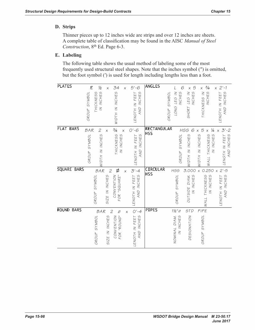
Structural Design Requirements for Design-Build Contracts Chapter 15
Page 15-98 WSDOT Bridge Design Manual M 23-50.17 June 2017
D. Strips
Thinnerpiecesupto12incheswidearestripsandover12inchesaresheets.AcompletetableofclassificationmaybefoundintheAISCManual of Steel Construction,8thEd.Page6-3.
E. Labeling
Thefollowingtableshowstheusualmethodoflabelingsomeofthemostfrequentlyusedstructuralsteelshapes.Notethattheinchessymbol(″)isomitted,butthefootsymbol(′)isusedforlengthincludinglengthslessthanafoot.
Page 11-10 Bridge Design Manual M 23-50 August 2006
Detailing Practice Chapter 11
E. Labeling
• The following table shows the usual method of labeling some of the most frequently used structural steel shapes. Note that the inches symbol (“) is omitted, but the foot symbol (‘) is used for length including lengths less than a foot.
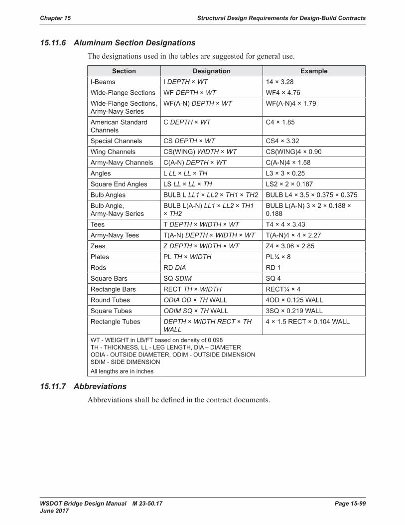
Chapter 15 Structural Design Requirements for Design-Build Contracts
WSDOT Bridge Design Manual M 23-50.17 Page 15-99 June 2017
15.11.6 Aluminum Section DesignationsThedesignationsusedinthetablesaresuggestedforgeneraluse.
Section Designation ExampleI-Beams I DEPTH × WT 14 × 3 .28Wide-Flange Sections WF DEPTH × WT WF4 × 4 .76Wide-Flange Sections, Army-Navy Series
WF(A-N) DEPTH × WT WF(A-N)4 × 1 .79
American Standard Channels
C DEPTH × WT C4 × 1 .85
Special Channels CS DEPTH × WT CS4 × 3 .32Wing Channels CS(WING) WIDTH × WT CS(WING)4 × 0 .90Army-Navy Channels C(A-N) DEPTH × WT C(A-N)4 × 1 .58Angles L LL × LL × TH L3 × 3 × 0 .25Square End Angles LS LL × LL × TH LS2 × 2 × 0 .187Bulb Angles BULB L LL1 × LL2 × TH1 × TH2 BULB L4 × 3 .5 × 0 .375 × 0 .375Bulb Angle, Army-Navy Series
BULB L(A-N) LL1 × LL2 × TH1 × TH2
BULB L(A-N) 3 × 2 × 0 .188 × 0 .188
Tees T DEPTH × WIDTH × WT T4 × 4 × 3 .43Army-Navy Tees T(A-N) DEPTH × WIDTH × WT T(A-N)4 × 4 × 2 .27Zees Z DEPTH × WIDTH × WT Z4 × 3 .06 × 2 .85Plates PL TH × WIDTH PL¼ × 8Rods RD DIA RD 1Square Bars SQ SDIM SQ 4Rectangle Bars RECT TH × WIDTH RECT¼ × 4Round Tubes ODIA OD × TH WALL 4OD × 0 .125 WALLSquare Tubes ODIM SQ × TH WALL 3SQ × 0 .219 WALLRectangle Tubes DEPTH × WIDTH RECT × TH
WALL4 × 1 .5 RECT × 0 .104 WALL
WT - WEIGHT in LB/FT based on density of 0 .098 TH - THICKNESS, LL - LEG LENGTH, DIA – DIAMETER ODIA - OUTSIDE DIAMETER, ODIM - OUTSIDE DIMENSION SDIM - SIDE DIMENSIONAll lengths are in inches
15.11.7 AbbreviationsAbbreviationsshallbedefinedinthecontractdocuments.
Structural Design Requirements for Design-Build Contracts Chapter 15
Page 15-100 WSDOT Bridge Design Manual M 23-50.17 June 2017
15.12 Bridge Load Rating15.12.1 General
Loadratingsshallbecompletedforallnew,widened,orrehabilitatedbridgeswheretherehabilitationalterstheloadcarryingcapacityofthestructure.LoadratingsshallbedoneimmediatelyafterthedesigniscompletedandratingcalculationsshallbefiledseparatelyinaccordancewithSection13.4andfilesshallbeforwardedtoWSDOT’sLoadRatingEngineer.Afinalstampedandsignedloadratingshallbeprovidedatleast90-dayspriortoopeninganybridgerequiringloadratingtotraffic.FinalapprovaloftheloadratingofabridgeshallrestwithWSDOT’sLoadRatingEngineer.
NewbridgesshallberatedbasedontheLoadandResistanceFactorRating(LRFR)methodinaccordancewiththeAASHTOManual For Bridge Evaluation(MBE), Chapter13ofthismanualandthischapter.NBIratingsshallbebasedontheHL-93truckandshallbereportedasaratingfactor.
15.12.2 Load Rating SoftwareForprestressedconcretegirderbridgesandX-Beams,useBridgeLinktoloadratestructuralelements.ForallothercaseswhereBridgeLinkcannotbeused,suchasbutnotlimitedto,orsteelstructuresorsegmentalboxes,CSiBridgeshallbeused.ObtainWSDOT’sLoadRatingEngineer’sapprovalfortheuseofanyothersoftwarepriortocommencinganywork.
Formorecomplexstructuressuchassteelcurvedgirdersandarches,differentsoftwaremaybeusedtoanalyzetheloadsafterobtainingapprovalfromWSDOT’sLoadRatingEngineer.AcceptablesoftwarecurrentlyincludesCSiBridge.
LoadsandcapacitiesshallbetabulatedinamannerthatwillmakeitsimpleforWSDOTtomanipulatethedatainthefuture.MethodoftabulationshallbeapprovedbyWSDOT’sLoadRatingEngineerpriortocommencinganywork.MicrosoftExcelshallbeusedfortabulation,andallcellsinthespreadsheetsshallbeunlockedandanyhiddencodeorfunctionsshallbeexplainedthoroughlyinthereport.Handcalculationsshallbeprovidedtoverifyallspreadsheets.

WSDOT Bridge Design Manual M 23-50.17 Page 15-101 June 2017
15.99 ReferencesAASHTOLRFD Bridge Design Specifications,LatestEditionandInterims.AmericanAssociationofStateHighwayandTransportationOfficials(AASHTO),Washington,D.C.
AASHTOGuide Specifications for LRFD Seismic Bridge Design (SEISMIC),LatestEditionandInterims.AmericanAssociationofStateHighwayandTransportationOfficials(AASHTO),Washington,D.C.
AASHTOStandard Specifications for Highway Bridges,17thedition
AASHTOManual for Bridge Evaluation
ACI355.4-11(2014) “Qualification of Post-Installed Adhesive Anchors in Concrete and Commentary,” AmericanConcreteInstitute,FarmingtonHills,MI.
WSDOTBridge Inspection ManualM36-64
WSDOTGeotechnical Design Manual M46-03
WSDOT Design ManualM22-01
WSDOTConstruction Manual M41-01
WSDOTLocal Agency GuidelinesM36-63
WSDOTStandard Specifications for Road, Bridge, and Municipal Construction (Standard Specifications) M41-10
WSDOT Standard Plans M21.01
WSDOTHydraulics ManualM23-03
WashingtonUtilitiesandTransportationCommissionClearance Rules and Regulations Governing Common Carrier Railroads
AmericanRailwayEngineeringandMaintenanceAssociation(AREMA)Manual for Railroad Engineering.Note:Thismanualisusedasthebasicdesignandgeometriccriteriabyallrailroads.UsethesecriteriaunlesssupersededbyFHWAorWSDOTcriteria.
TheUnionPacificRailroad“Guidelines for Design of Highway Separation Structures over Railroad (Overhead Grade Separation)”

Structural Design Requirements for Design-Build Contracts Chapter 15
Page 15-102 WSDOT Bridge Design Manual M 23-50.17 June 2017
This page intentionally left blank.