Embed Size (px)
Citation preview

GEOTECHNICAL REPORT
BRIDGE B-1658 REPLACEMENT
EDEN VALLEY ROAD
HUMBOLDT COUNTY, NEVADA
APRIL 2017

DEPARTMENT OF TRANSPORTATION
MATERIALS DIVISION
GEOTECHNICAL SECTION
GEOTECHNICAL REPORT EDEN VALLEY ROAD BRIDGE B-1658 REPLACEMENT
HUMBOLDT COUNTY, NEVADA
E.A. 73701
April 2017
Prepared by: ______________________________
Jesse Ruzicka, P.E. Principal Materials Engineer - Geotechnical
Reviewed by: ______________________________
Mike Griswold, P.E. Assistant Chief Materials Engineer - Geotechnical
Approved by: ______________________________
Darin Tedford, P.E. Chief Materials Engineer
ii

TABLE OF CONTENTS 1.0 INTRODUCTION 1
1.1 Project Location and Purpose 1
1.2 Project Description 2
2.0 SCOPE OF WORK AND REPORT LIMITATIONS 3
3.0 GEOLOGIC CONDITIONS AND SEISMICITY 4
3.1 Local Site Geology 4
3.2 Geologic Setting 5
3.3 Site Classification and Seismic Parameters 6
4.0 FIELD INVESTIGATION 8
4.1 Geophysical Site Investigation 9
4.2 Exploratory Boreholes 14
5.0 FOUNDATION RECOMMENDATIONS 15
5.1 General 15
5.2 Foundation Loads 16
5.3 Pile Design Recommendations 19
5.4 Lateral Earth Pressure on Abutment Walls 21
5.5 Approach Embankment Settlement 23
5.6 Earthquake-Induced Soil Liquefaction 23
5.7 Earthquake-Induced Downdrag 23
6.0 DYNAMIC ANALYSIS: PILE DRIVABILITY 24
7.0 REFERENCES 26
APPENDICES
APPENDIX A Boring Logs
APPENDIX B Laboratory Test Results
iii

Bridge B-1658 Replacement April 2017 Eden Valley Road
1
1.0 Introduction
1.1 Project Location and Purpose
The Nevada Department of Transportation
(NDOT), in cooperation with Humboldt
County, will be replacing substandard
structure, B-1658, on Eden Valley Road north
of Golconda, Nevada in Township 36 North ,
Range 40 East, Section 21. This structure
crosses the Humboldt River roughly 2 miles
north of Interstate 80, 1.8 miles Northeast of
Golconda, Nevada, and roughly 15 miles
Northeast of Winnemucca, NV. Eden Valley
Road is a Humboldt County maintained road
that generally runs North/South and provides
access to agriculture, ranching, and public
lands. Eden Valley road connects I-80 with US95 and SR290 approximately 22 miles north of Winnemucca
through Paradise Valley.
B-1658 Project Location Map
B-1658 Project Location Map

Bridge B-1658 Replacement April 2017 Eden Valley Road
2
1.2 Project Description
Structure B-1658 was built in 1974
and crosses the primary Humboldt
River channel, utilizing a two-span,
simply supported, reinforced
concrete girder bridge. The
existing central pier appears to be a
concrete curtain wall with 8
embedded cylindrical steel pipe
piles driven to an unknown depth.
The abutments appear to be
standard vertical concrete wall
abutments with 5 cylindrical steel
pipe piles driven to an unknown
depth. B-1658 received an overall sufficiency rating of 42.1 during its inspection in 2010. This substandard
score is attributed to the overall scour potential at the center pier, exposed piles at both the center pier and
west abutment, as well as previous scour/undermining at the west abutment. These factors as well as the
overall condition of the structure makes this a candidate for replacement.
Eden Valley Bridge B-1658 -Scour
Eden Valley Bridge B-1658

Bridge B-1658 Replacement April 2017 Eden Valley Road
3
The proposed new structure will be approximately 50 feet from the center of the existing bridge to the north
on downstream side. The new bridge will be a single span, simply supported structure, roughly 30 ft. longer
than the original structure. This will eliminate the center pier, as well as set back the abutments from the
active channel. The proposed foundation type will be driven steel pipe piles. The proposed superstructure
will be precast concrete box girders founded on standard seat type abutments. The increased span will
result in higher loads, increasing the overall depth of the superstructure, which will result in an increased
roadway grade. The preliminary plans call for a realignment of Eden Valley road to the north, allowing the
new structure to be built while using the existing structure for traffic.
2.0 Scope of Work and Limitations
2.1 Scope of Work
The purpose of this geotechnical investigation was to determine the subsurface soil and groundwater
conditions, evaluate the feasibility of the proposed foundation type, provide recommended geotechnical
design values, and identify potential risk factors for construction. The actual scope of work completed for
this report was a review of published maps and reports, three subsurface exploratory borings, a geophysical
survey, laboratory soil testing, geotechnical engineering analysis, design, and documentation of the
findings.
The report appendices contain supporting documents including the boring logs, laboratory test summaries,
the results of geophysical testing, and associated calculations. The calculations follow the guidelines of
AASHTO LRFD Bridge Design Specifications Sixth Edition, 2012, with interims where appropriate.
2.2 Limitations
This report follows the guidelines of generally accepted geotechnical practice. The Geotechnical Report is
based on field observations of the project Geotechnical Engineer, a summary of the subsurface exploration,
and the results of laboratory testing of collected soil samples. The report is based on our interpretations of
the findings in the three exploratory borings and the geophysical investigation. Therefore, this report may
not quantify the exact natural variation of in-situ soils or depth to water. Depth to water can vary based on

Bridge B-1658 Replacement April 2017 Eden Valley Road
4
overall weather patterns, seasonal variation, and local agricultural practice making it difficult to predict at
any given time. Any additional analysis or interpretations of the boring logs and other test data, provided
by third parties, are not the responsibility of the Department (NDOT). If conditions are encountered during
construction, which differ from those found in this report, or if the scope of construction is significantly
changed, the Geotechnical Section should be notified to provide additional recommendations.
3.0 Geologic Conditions and Seismicity
3.1 Local Site Geology This site is primarily mapped in the geologic unit, Qya (Quaternary Younger Alluvium). The near surface
deposits are likely flood plain deposits from the Humboldt River, lake bed deposits from pre-late
Pleistocene Lake Lahontan, as well as alluvial deposits from the mountain ranges to the north and east. The
United States Department of Agriculture Web Soil Survey (USDA-WSS) maps the upper 5 ft. of soils near
B-1658 as Humboldt silty clay loam (Unit 321) defined by silty clay loam and stratified silty clay loam to
clay. These descriptions are similar to the conditions encountered during the site visit and subsequent
exploration. Ariel imagery indicates the possible presence of long term Humboldt River channel instability
in the area which may cause some variability in the near surface deposits both laterally and vertically.
Geologic Map USGS DS249 1:250,000 scale

Bridge B-1658 Replacement April 2017 Eden Valley Road
5
3.2 Geologic Setting: Seismicity and Faulting
Geologic Setting
The project is generally located in the Basin and Range province which encompasses the majority of the
State of Nevada. The Basin and Range province is generally composed of north trending mountain ranges
separated by alluvial, normal-fault bounded basins. Regionally, the project falls on alluvial and flood plain
deposits from Osgood range to the North and Humboldt River flood plain.
Seismicity and Faulting
The Winnemucca region has four major fault-block mountain ranges. There are numerous mapped
Quaternary faults located in the region which run along the boundary of the alluvial basins and mountain
ranges. The closest fault zones to the project site are the Eastern Osgood mountains fault zone, Eastern
Osgood piedmont fault, Edna mountain fault, and the Grass Valley fault zone. Although earthquakes can
be triggered along these fault lines, the predicted ground accelerations are lower than other regions in
Nevada, especially along the Eastern Sierra Range. The ground accelerations that should be used in the
design are discussed further below.
USGS Fault Mapping

Bridge B-1658 Replacement April 2017 Eden Valley Road
6
3.3 Site Class Determination and Seismic Parameters
The seismic provisions of the AASHTO LRFD specifications Article 3.10 are applied to bridge design in
Nevada. Earthquake force effects were determined in accordance with AASHTO LRFD article 3.10.
Seismic coefficients from the AASHTO LRFD Specifications used for design must meet or exceed the
minimum seismic coefficients shown in Figure 12.3-H of the NDOT Structures Manual unless otherwise
approved by the Chief Structures Engineer (NDOT Structures Manual, pg. 12-21).
AASHTO 3.10.1 recommends selecting your Peak Ground Acceleration (PGA) based on the Horizontal
Peak Ground acceleration coefficient with seven percent probability of exceedance in 75 years (Approx.
1000 year return period). The PGA, short, and long period response spectral accelerations Ss and S1 for the
site were obtained using the United States Geological Survey (USGS) Design Maps Tool. For the project
site, AASHTO recommends a PGA of 0.158g, from figure 3.4.1-2. These seismic design parameters are
based on Site Class B and adjustments should be made for other site classes, as needed, as shown in
AASHTO 3.4.2.3.
Seismic Design Parameters
Humboldt County
PGA(g) SS(g) S1(g)
0.186 0.45 0.15(1) (1) Based on minimum value provided in NDOT Structures Manual.
The Site Class for the project location is Site Class D, in accordance with Table 3.10.3.1-1 of AASHTO
Guide Specifications for LRFD Bridge Design, based on the average shear wave velocity of the upper 100
ft. (Vs100). The average shear wave velocity was obtained utilizing Refraction MicroTremor (ReMiTM)
geophysical testing methods as discussed further below in Field Investigation.

Bridge B-1658 Replacement April 2017 Eden Valley Road
7
Eden Valley Road B-1658 Site Classification
Average Shear Wave Velocity by ReMiTM Method (VS100)
Seismic Line Average Shear Wave Velocity ,VS100 (ft/s) Site Classification
Seismic Line #1 1132 Site Class D
Seismic Line #2 1109 Site Class D
Seismic Line #3 1148 Site Class D
Site Classification from ReMiTM Shear Wave Velocity Measurement
The general Humboldt County, NV seismic design parameters must be modified from Site Class B to Site
Class D. The final recommended design response spectrum is shown below:
B-1658 Design Response Spectrum
0.000
0.200
0.400
0.600
0.800
1.000
1.200
1.400
0.000 0.500 1.000 1.500 2.000 2.500 3.000 3.500
Spec
tral
Res
pons
e Ac
cler
atio
n Sa
(g)
Period, Tm (seconds)
B-1658 Eden Valley Road Design Response Spectrum
Site Class D: As=0.27g SDS=0.65g SD1= 0.33g

Bridge B-1658 Replacement April 2017 Eden Valley Road
8
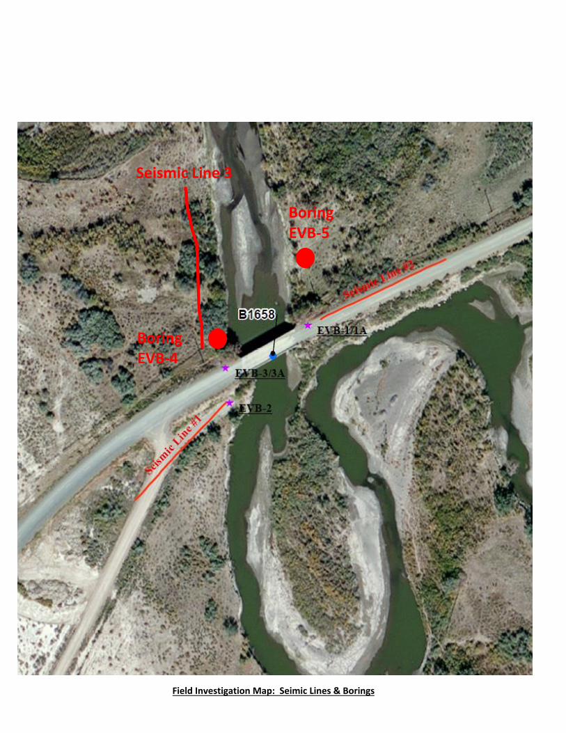
4.0 Field Investigation The NDOT Geotechnical section performed site investigations at the project site in October 2013, April
2014, and September 2016 at the locations shown on the following map:
Field Investigation Map: Seismic Lines & Boring Locations
Seismic Line 3
Boring EVB-4
Boring EVB-5

Bridge B-1658 Replacement April 2017 Eden Valley Road
9
4.1 Geophysical Site Investigation
Seismic Data Collection
For this survey, geophones were spaced 20ft. apart for all lines. Background (ambient) noise was used to
generate seismic waves during the ReMiTM survey. Occasionally, light hammer strikes offset from the end
of the seismic line were utilized to increase the high frequency energy during noise recordings. This process
can aid interpretation of subsurface shear wave velocity at shallow depths. Occasionally, walking and other
light disturbances can be used to increase the amplitude of noise energy over a variety of frequencies when
working in quiet environments. Noise recordings for ReMiTM analysis were 30 second recording periods
with a 2 ms sampling interval. Each individual record is stored in SEG-Y format. In general, 10 individual
noise recordings are made for each line. Individual records are not stacked or modified until final
processing.
ReMiTM Seismic Data Analysis
The analysis and interpretation of the seismic data collected for this project was performed by a consultant,
Optim of Reno, NV. The field exploration, noise data acquisition, location survey, and preliminary data
verification was performed by geotechnical staff at NDOT. The noise data collected for ReMiTM was
analyzed using the proprietary software SeisOpt ReMiTM, developed by Optim of Reno, NV.

Bridge B-1658 Replacement April 2017 Eden Valley Road
10
Seismic Line 1
Seismic Line 2

Bridge B-1658 Replacement April 2017 Eden Valley Road
11
Seismic Line 3

Bridge B-1658 Replacement April 2017 Eden Valley Road
12
4238.4
4248.4
4258.4
4268.4
4278.4
4288.4
4298.4
4308.4
4318.4
4328.4
4338.4
4348.4
0 500 1000 1500 2000 2500 3000
Dep
th, f
t
Vs100' (Line 1)= 1132 ft/s
Vs100' (Line 2) = 1109 ft/s
Seismic Lines 1&2 ReMi Vs Model

Bridge B-1658 Replacement April 2017 Eden Valley Road
13
Zero depth refers to elevation 4339 feet.
4239.0
4249.0
4259.0
4269.0
4279.0
4289.0
4299.0
4309.0
4319.0
4329.0
4339.00 1000 2000 3000 4000 5000 6000
Dep
th, f
t
Vs100' = 1148 ft/s
Seismic Line 3 ReMi Vs Model

Bridge B-1658 Replacement April 2017 Eden Valley Road
14
4.2 Exploratory Borings
The subsurface exploration consisted of five exploratory borings drilled with a Diedrich D-120 truck
mounted drilling rig, NDOT unit #1082. Soil samples and standard penetration resistance values (N-values)
were obtained utilizing the Standard Penetration Test (ASTM D 1586). The test was performed with a
sampler driven 18” (unless otherwise noted in the logs) into the bottom of the boring using a 30 in. drop of
a 140 lb. automatic hammer. Soil samples were collected using a Standard Penetration Test Sampler (SPT
Sampler) and ring-lined (ASTM D 3550) Modified California Sampler (CMS). The uncorrected field blow
counts are shown on the boring logs in Appendix A. These blow counts have not been corrected for energy,
sampler type, rod length, or hammer type. The energy transfer ratio (ER) for NDOT Unit 1082 is 86%.
Field CMS blow counts can be converted to field SPT blow counts by multiplying the field CMS blow
counts by a factor of 0.62 as stated in the Key to the Boring Logs (Appendix A). All soil samples were
either classified, using laboratory testing data, according to ASTM D 2487 or described and identified
according to ASTM D 2488. SPT-Torque (SPT-T) values were also obtained on selected depth intervals,
to estimate unit skin friction values. This procedure is based on the ASCE Journal of Geotechnical and
Geoenvironmental Engineering/Volume 130 Issue 5 – May 2004, “Unit Skin Friction from the Standard
Penetration Test Supplemented with the Measurement of Torque”.

Bridge B-1658 Replacement April 2017 Eden Valley Road
15
5.0 Foundation Design Recommendations
5.1 General We recommend driven pile foundations, using closed-ended pipe piles for the replacement structure B-
1658. The pipe piles should be 18 inches in diameter with the nominal wall thickness of 0.5 inches and
Grade 3 steel.
The proposed pile foundation arrangement as provided by the Structural Engineers for B-1658 is as follows:
B-1658 Bridge Foundation Piles
Two Pile Rows per Abutment
Abutment 1 5 per row
Abutment 2 5 per row
The estimated pile lengths are determined based on scour depth, soil bearing capacity, and drivability
analysis.
Based on the provided information from NDOT Hydraulic Section, the contraction scour elevation for the
100-year event (Design Flood) is 4314 feet and the contraction scour elevation for 500-year event (Check
Flood) is 4308 feet. NDOT Hydraulic Section is proposing to install riprap to mitigate scour. However,
riprap revetment can only eliminate the abutment scour. The bridge still has to be designed for contraction
scour.

Bridge B-1658 Replacement April 2017 Eden Valley Road
16
5.2 Foundation Loads The Structural Engineer provided the following foundation design loads:
Since the proposed pile group arrangements are simple (two rows of piles per support), the group capacity
was analyzed using Simple Static Equilibrium (“Push-Pull couple) method to calculate axial compression,
axial pull-out, and lateral loads on top of each pile. The applied overturning moments at the top of the pile
groups were resolved into these axial compression and axial pull-out loads using this method.

Bridge B-1658 Replacement April 2017 Eden Valley Road
17
Plan
The geotechnical axial compression resistance of a single driven pile at Strength I includes the
effect of scour at the design flood (100-year flood).
For Service I, the settlement (vertical deformation) includes the effect of scour at the design flood
(100-year flood).
For Extreme Event I, the critical load case consists of applying the full factored force effect in the
longitudinal direction with 30 percent of the force effects in the transverse direction (AASHTO
3.10.8).

Bridge B-1658 Replacement April 2017 Eden Valley Road
18
Load combinations that represent the maximum vertical load, the maximum overturning moment,
the maximum horizontal load, and the maximum overturning moment combined with the
minimum vertical load produce the controlling effects in the piles as provided below.
Factored Force Effect
Abutment 1
LIMIT STATE AXIAL LOAD
(Kips)
TRANSVERSE
SHEAR
(Kips)
MOMENT
(ft-kips)
Strength I 2273.7 0.0 4851.2
Strength II 2394.3 0.0 3848.2
Service I 1696.1 0.0 2716.8
Extreme Event I 1528.4 724.0 7208.7
Factored Force Effect
Abutment 2
LIMIT STATE AXIAL LOAD
(Kips)
TRANSVERSE
SHEAR
(Kips)
MOMENT
(ft-kips)
Strength I 2249.1 0.0 1131.1
Strength II 2375.3 0.0 978.4
Service I 1682.1 0.0 591.0
Extreme Event I 1524.9 683.8 6677.2
5.3 Driven Pipe Pile Design Recommendations The soil profile below the pile caps mainly consists of cohesionless sand and gravel with
occasional cobbles/boulders. The soil below the 100-year scour depth is very dense. The pile
capacity is a combination of side resistance and end-bearing. The side resistance and the end-

Bridge B-1658 Replacement April 2017 Eden Valley Road
19
bearing capacities were estimated using the Nordlund/Thurman Method (AASHTO Table
10.5.5.2.3-1).
LIMIT STATE RESISTANCE FACTOR
NOMINAL AXIAL
COMPRESSION
APPLICATION
Strength φdyn = 0.65 Based on Field Dynamic Analysis (PDA) AASHTO Table 10.5.5.2.3-1
Service 1.0 AASHTO Table 10.5.5.2.3-1 Extreme Event I (EQ)
1.0 AASHTO Table 10.5.5..3.3
Extreme Event II (Check Flood, 500-year flood event)
1.0 AASHTO Table 10.5.5..3.2
0.00
10.00
20.00
30.00
40.00
50.00
60.00
70.00
80.00
90.000 100 200 300 400 500 600
Dept
h (ft
)
Capacity (kips)
Eden Valley Bridge B-1658, 18" Pipe Pile Capacity
Pile Capacity SPT Blowcounts
Pile Cap Elevation 4330 feet
100-year Scour Depth Elevation 4314 feet
AASHTO LRFD Resistance Factors

Bridge B-1658 Replacement April 2017 Eden Valley Road
20
SUMMARY TABLE We suggest that the following summary tables be included in the bridge construction plans:
BRIDGE B-1658
LOCATION MIN. TIP
ELEVATION
(FEET)
DESIGN TIP
ELEVATION
(FEET)
REQUIRED
PILE DRIVING RESISTANCE
(KIPS)
ABUTMENT #1 4295 4290 430
ABUTMENT # 2 4295 4290 430
We anticipate that piles lengths of 40 feet will be acceptable for the project.
Difficult driving conditions are anticipated and preboring of holes should be anticipated. If preboring is used to advance through cobbles/boulders, the maximum boring diameter shall not exceed 2/3 of the pile diameter. Preboring shall be in accordance with Section 508.03.04 of the 2014 Standard Specifications for Road and Bridge Construction.
Soil Parameters for Laterally Loaded Piles
Soil Effective Unit Weight (buoyant = 58 lb/ft3)
Soil internal Friction Angle = 36° (4330 to 4300 feet)
Soil internal Friction Angle = 38° (4300 to 4250 feet)
Soil Subgrade Modulus (KS) = 90 lb/in3 (4330 to 4300 feet)
Soil Subgrade Modulus (KS) = 140 lb/in3 (4300 to 4250 feet)
Pile Cap Elevation = 4330 to 4329 feet
100-Year Scour Depth Elevation = 4314 feet
Bridge B-1658 Replacement April 2017 Eden Valley Road
21
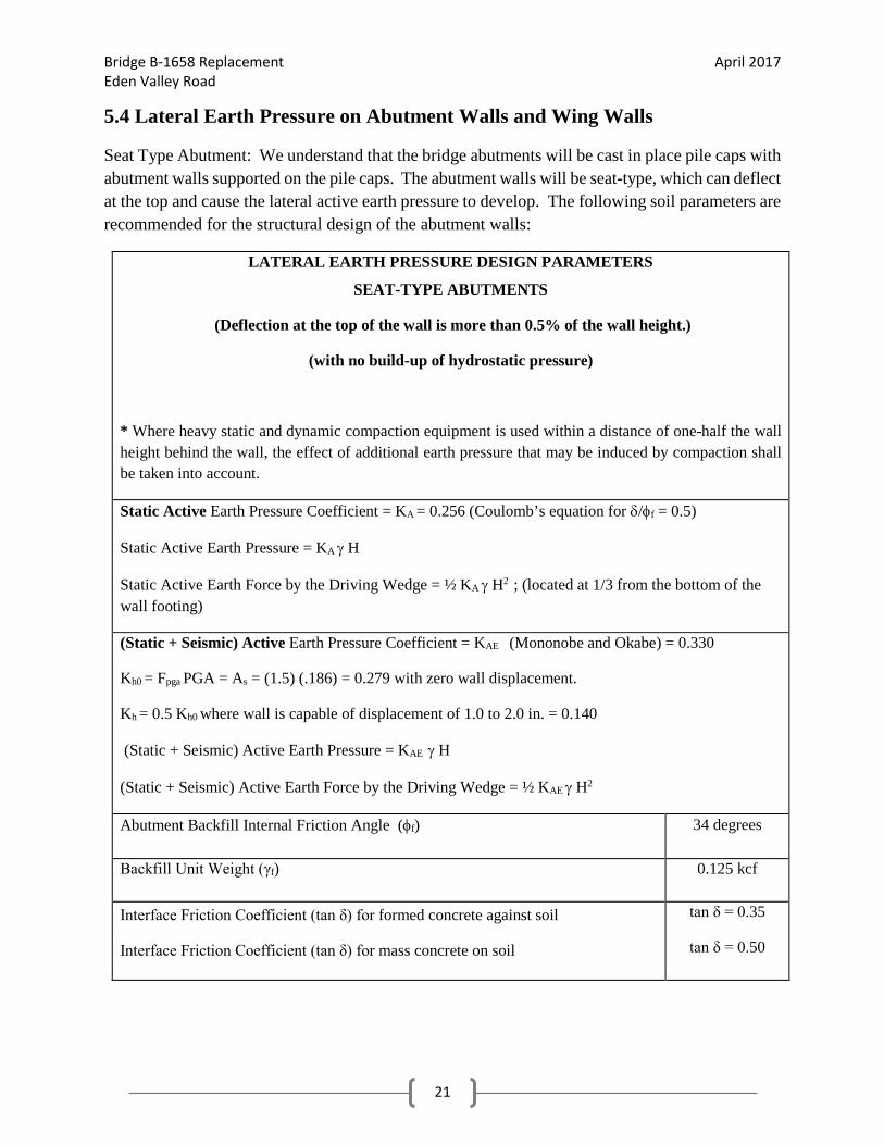
5.4 Lateral Earth Pressure on Abutment Walls and Wing Walls
Seat Type Abutment: We understand that the bridge abutments will be cast in place pile caps with abutment walls supported on the pile caps. The abutment walls will be seat-type, which can deflect at the top and cause the lateral active earth pressure to develop. The following soil parameters are recommended for the structural design of the abutment walls:
LATERAL EARTH PRESSURE DESIGN PARAMETERS
SEAT-TYPE ABUTMENTS
(Deflection at the top of the wall is more than 0.5% of the wall height.)
(with no build-up of hydrostatic pressure)
* Where heavy static and dynamic compaction equipment is used within a distance of one-half the wall height behind the wall, the effect of additional earth pressure that may be induced by compaction shall be taken into account.
Static Active Earth Pressure Coefficient = KA = 0.256 (Coulomb’s equation for δ/φf = 0.5)
Static Active Earth Pressure = KA γ H
Static Active Earth Force by the Driving Wedge = ½ KA γ H2 ; (located at 1/3 from the bottom of the wall footing)
(Static + Seismic) Active Earth Pressure Coefficient = KAE (Mononobe and Okabe) = 0.330
Kh0 = Fpga PGA = As = (1.5) (.186) = 0.279 with zero wall displacement.
Kh = 0.5 Kh0 where wall is capable of displacement of 1.0 to 2.0 in. = 0.140
(Static + Seismic) Active Earth Pressure = KAE γ H
(Static + Seismic) Active Earth Force by the Driving Wedge = ½ KAE γ H2
Abutment Backfill Internal Friction Angle (φf) 34 degrees
Backfill Unit Weight (γf) 0.125 kcf
Interface Friction Coefficient (tan δ) for formed concrete against soil
Interface Friction Coefficient (tan δ) for mass concrete on soil
tan δ = 0.35
tan δ = 0.50

Bridge B-1658 Replacement April 2017 Eden Valley Road
22
General Seismic Design Parameters
Nevada Humboldt County: Based on NDOT Bridge Structures Division policy:
• Peak Ground Acceleration Coefficient (PGA) = 0.186g
• Short-Period Spectral Acceleration Coefficient (Ss) = 0.45
• Long-Period Spectral Acceleration Coefficient (S1) = 0.15
AASHTO LRFD Table 3.10.33.1-1, Site Class Definitions: the site generally can be classified
as Site Class D.
Response Modification Factor = R = varies, see AASHTO Table 3.10.7.1-1
Vertical Acceleration Coefficient = 0 [AASHTO Appendix A11]
Poisson’s ratio for granular backfill material = µ = 0.30
Young Modulus for granular backfill material (Es; AASHTO Table C10.4.6.3-1):
• Es= 0.139N160 (ksi) ≈ 4.448 ksi ; for N160 = 32 (estimated)]
Shear Modulus (G) for granular backfill material = Es / 2(1+µ) ≈1.7 ksi

Bridge B-1658 Replacement April 2017 Eden Valley Road
23
5.5 Approach Embankment Settlement Settlement for the abutment approach fills were analyzed based on a maximum fill height of 20
feet, with 2(H):1(V) side slopes. Based on our analysis, we estimate that the proposed approach
fills will experience less than 1 inch of total settlement and the differential settlement of 0.5 inches. 5.6 Earthquake-induced soil liquefaction (AASHTO 10.7.4) is evaluated under Extreme Event
I limit state. Initial liquefaction screening criteria to determine whether or not a liquefaction
analysis is needed for this bridge were done according to AASHTO 10.5.4.2 Since (N1)60 of the
soil layers is greater than 25 blows/ft and the normalized shear wave velocity, VS1, is greater than
660 feet/second for soils below the design scour depth, the potential for soil liquefaction
occurrence at this site is minimal.
5.7 Earthquake-induced downdrag (AASHTO 10.7.4, 3.11.8) were applied to the piles in
combination with other applied loads under Extreme Event I limit state (AASHTO 3.11.8). Since
all piles resistance are based on combination of skin friction and end bearing and the pile tips will
be tipped into very dense soils and the equivalent footing will be located within the very dense
granular soil or very stiff to hard cohesive soil, the possibility of downdrag force on piles are
negligible.

Bridge B-1658 Replacement April 2017 Eden Valley Road
24
6.0 Dynamic Analysis: Pile Drivability
Pile drivability is truly a construction limit state, but it is treated as a strength limit state.
Driving resistance of the driven piles (the ability of the piles to withstand stresses induced during installation) was evaluated by wave equation method, using computer program GRLWEAP 2010. In addition, the wave equation analyses determine the driving stresses and blow counts based upon hammer size. Thus, the wall thickness and required hammer size were determined to reach a desired capacity. In these analyses, high strength steel (50 ksi) was used to allow for higher driving stress.
Pile driving stress (σdr) anywhere in the pile determined from the analysis shall be as:
σdr ≤ 0.9 φdafy
φda: AASHTO Table 10.5.5.2.3-1
We recommend pile driving points (shoes) be used on all the piles to minimize the pile damage during the driving.
A trial hammer Delmag D30-32 was used in GRLWEAP 2010 to check the drivability of the piles at this bridge. The output shows that the piles are drivable and the compression stresses on the piles are within the limit.

Bridge B-1658 Replacement April 2017 Eden Valley Road
25
02-Sep-2016NDOT Geotechnical GRLWEAP Version 2010Bridge B-1658, Eden Valley Road
02-Sep-2016NDOT Geotechnical GRLWEAP Version 2010Bridge B-1658, Eden Valley Road
Com
pres
sive
Stre
ss (k
si)
0
10
20
30
40
50
Tens
ion
Stre
ss (k
si)
0
10
20
30
40
50
Blow Count (bl/ft)
Ulti
mat
e C
apac
ity (k
ips)
0 200 400 600 800 1000 12000
400
800
1200
1600
2000
Blow Count (bl/ft)
Stro
ke (f
t)
0 200 400 600 800 1000 12000
2
4
6
8
10
DELMAG D 30-32
Ram Weight 6.60 kipsEfficiency 0.800Pres sure 1260 (90%) ps i
Helm et Weight 3.40 kipsHam m er Cushion 109975 kips /inCOR of H.C. 0.800
Skin Quake VariableToe Quake VariableSkin Dam ping VariableToe Dam ping Variable
Pile LengthPile Top Area
40.00 27.49
ft ft in2
Pile Model
Res . Shaft = 16 %(Proportional)

Bridge B-1658 Replacement April 2017 Eden Valley Road
26

Bridge B-1658 Replacement April 2017 Eden Valley Road
27
NDOT Geotechnical 02-Sep-2016Bridge B-1658, Eden Valley Road GRLWEAP Version 2010
Maximum Maximum Ultimate Compression Tension Blow Capacity Stress Stress Count Stroke Energy
kips ksi ksi bl/ft ft kips-ft
100.0 19.31 0.34 6.3 5.08 30.53 200.0 24.11 0.05 15.6 6.16 26.97 300.0 26.73 0.08 26.3 6.88 26.26 400.0 28.23 0.16 37.8 7.29 26.14 500.0 31.12 0.58 53.0 7.66 26.64 600.0 33.41 1.17 77.6 7.98 26.87 700.0 35.66 1.34 117.2 8.40 28.04 800.0 37.54 1.67 198.7 8.79 29.46 900.0 38.42 1.67 399.1 8.96 29.99
1000.0 39.23 1.59 1273.6 9.16 30.57

Bridge B-1658 Replacement April 2017 Eden Valley Road
28
7.0 References
1. FHWA Design and Construction of Driven Pile Foundations, Publication No. FHWA
NHI-05-042, April 2006
2. Adams, K.Kenneth, and Sawyer, T.L., compilers, 1999, Fault number 1294, Singatse
Range fault zone, in Quaternary fault and fold database of the United States: U.S.
Geological Survey website, http://earthquakes.usgs.gov/hazards/qfaults, accessed
06/30/2014 02:48 PM.
3. California Department of Transportation, CALTRANS Acceleration Response Spectra
(ARS), ARS Online Version 2.3.06, accessed at,
http://dap3.dot.ca.gov/ARS_Online/index.php, accessed date: 07/29/2014.
4. American Association of State Highway and Transportation Officials (AASHTO), 2012,
AASHTO LRFD Bridge Design Specifications, Customary, U.S. Units, 6th Edition:
Washington DC
5. Hunt, John H, Ayres Associates, Nevada Department of Transportation, 2010, Scour
Critical Bridge Plan of Action B-1610.
6. Crafford, A.E.J., 2007, Geologic Map of Nevada: U.S. Geological Survey Data Series 249.
7. Soil Survey Staff, Natural Resources Conservation Service, United States Department of
Agriculture. Web Soil Survey. Available online at http://websoilsurvey.nrcs.usda.gov/.
Accessed on 07/24/2014.
8. Optim Software, Available online at http://www.optimsoftware.com, Accessed on
12/14/2014.
9. Nevada Department of Transportation, NDOT Structures Manual, 2008.
Field Investigation Map: Seimic Lines & Borings
Seismic Line 3
Boring EVB-4
Boring EVB-5


S,W,PI
S,W,PI
S,W,PI
S,W
S,W,PI
S,W,PI
S,PI
S,PI
18
17
15
16
19
7
38
20
6" H.S.A. on the shoulder of gravel road
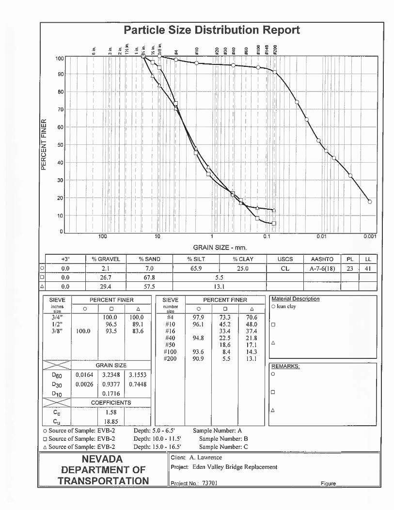
SILTY SAND WITH GRAVEL , moist, lightyellowish brown (10YR 6/4), subangular tosubrounded gravel, -200=21% , Sand=63%,Gravel=16%, -3/4"=94%
SILTY SAND , moist, light yellowish brown(10YR 6/4), -200=20% , Sand=70%,Gravel=10%, -3/4"=100%
SILTY SAND ,moist, dark greyish brown(10YR 4/2), -200=24% , Sand=64%,Gravel=12%, -3/4"=100%
SANDY SILTY CLAY ,moist , dark greyishbrown (10YR 4/2), -200=70% , PI=6,Sand=30%
POORLY GRADED SAND ,moist, dark greygravel, -200=2% , Sand=84%, Gravel=14%,-3/4"=100%
WELL GRADED SAND WITH SILT OR CLAYAND GRAVEL , moist, dark greygravel,subangular to subrounded gravel,-200=6% , Sand=66%, Gravel=28%,-3/4"=100%
WELL GRADED SAND WITH SILT ANDGRAVEL , wet, dark grey gravel,subangularto subrounded gravel, -200=7% , Sand=77%,Gravel=16%, -3/4"=100%
LEAN CLAY , wet, dark grey (5YR 4/1),PI=31
POORLY GRADED SAND WITH GRAVEL ,wet,subangular to subrounded gravel, -200=3%, Sand=71%, Gravel=26%, -3/4"=98%
POORLY GRADED SAND WITH SILT ANDGRAVEL , wet, subangular to subroundedgravel, -200=6% , Sand=63%, Gravel=31%,-3/4"=100%
*SPT-T=SPTTorque(Peak-Residual),referenceGeotechnicalReport fordetails.
(C) SPT-T(75-55) lb-ft
* coarsergravel? somedrill vibration
(D)SPT-T(220-80) lb-ft
(F)SPT-T(60-45) lb-ft;Sampler Wet
(H)SPT-T(55-35) lb-ft
10.90
13.00
16.50
21.10
23.00
26.50
10
7
6
8
11
3
19
9
SM
CLML
SP
SWSM
CL
SP
SP
SPT
SPT
SPT
CMS
SPT
SPT
CMS
SPT
75
80
80
85
80
85
80
80
2.50
5.00
10.00
15.00
16.50
20.00
25.00
26.50
4.00
6.50
11.50
16.50
18.00
21.50
26.50
28.00
A
B
C
D
E
F
G
H
8
8
10
5
7
5
15
8
8
10
9
8
8
4
19
11
STATION
OFFSET
ENGINEER
EQUIPMENT
OPERATOR
SHEET 1 OF 2
MATERIAL DESCRIPTION
73701 Eden Valley Bridge Replacement (B-1658)
BACKFILLED
10/29/13
ELEV. ft
6 inchIncrements
10/29/13
TYPE
SAMPLE
4331.9Automatic (ETR 86%)
DEPTH ft
DATE
EVB-1
DRILLINGMETHOD
Eden Valley Road, Humboldt County, NV
PercentRecov'd
73701
START DATE
END DATE
JOB DESCRIPTION
LOCATION
BORING
E.A. #
GROUND ELEV.
HAMMER DROP SYSTEM
LawrenceDiedrich D-120 (Unit 1082)Altamirano
4345.9
4340.9
4335.9
4330.9
4325.9
5
10
15
20
25
5
10
15
20
25
GROUNDWATER LEVEL
EXPLORATION LOG
6" H.S.A.
USCSGroupLast
1 footDEPTH
(ft)ELEV.
(ft)
DATE
REMARKSBLOW COUNT
10/29/13
LAB TESTS
4350.90 (ft)19.00
NO.
NV
_DO
T 7
3701
_E
DE
NV
ALL
EY
BR
IDG
E.G
PJ
NV
_DO
T.G
DT
6/1
9/15

S,PI25
POORLY GRADED SAND , wet, samplelikely heaving sand into auger, -200=4% ,Sand=94%, Gravel=2%, -3/4"=100%,-3/8"=100%
END EVB-1 @ 36.5'
* sands heavinginto stem,difficulty pullinginner string forsamplerattachment, drillto 35'.
(I) *sandheaving intoauger stem
33.00
36.5019
SM
SP
SPT 75
35.00
36.50I
26
STATION
OFFSET
ENGINEER
EQUIPMENT
OPERATOR
SHEET 2 OF 2
MATERIAL DESCRIPTION
73701 Eden Valley Bridge Replacement (B-1658)
BACKFILLED
10/29/13
ELEV. ft
6 inchIncrements
10/29/13
TYPE
SAMPLE
4331.9Automatic (ETR 86%)
DEPTH ft
DATE
EVB-1
DRILLINGMETHOD
Eden Valley Road, Humboldt County, NV
PercentRecov'd
73701
START DATE
END DATE
JOB DESCRIPTION
LOCATION
BORING
E.A. #
GROUND ELEV.
HAMMER DROP SYSTEM
LawrenceDiedrich D-120 (Unit 1082)Altamirano
4315.9
4310.9
4305.9
4300.9
4295.9
35
40
45
50
55
35
40
45
50
55
GROUNDWATER LEVEL
EXPLORATION LOG
6" H.S.A.
USCSGroupLast
1 footDEPTH
(ft)ELEV.
(ft)
DATE
REMARKSBLOW COUNT
10/29/13
LAB TESTS
4350.90 (ft)19.00
NO.
NV
_DO
T 7
3701
_E
DE
NV
ALL
EY
BR
IDG
E.G
PJ
NV
_DO
T.G
DT
6/1
9/15

6" H.S.A. from ground surface
Immediatly Adjacent to EVB-1, drill straightdown to 40.0' to try and bypass heaving sands
*SPT-T=SPTTorque(Peak-Residual),referenceGeotechnicalReport fordetails.
2.00
STATION
OFFSET
ENGINEER
EQUIPMENT
OPERATOR
SHEET 1 OF 3
MATERIAL DESCRIPTION
73701 Eden Valley Bridge Replacement (B-1658)
BACKFILLED
10/30/13
ELEV. ft
6 inchIncrements
10/30/13
TYPE
SAMPLE
4331.9Automatic (ETR 86%)
DEPTH ft
DATE
EVB-1A
DRILLINGMETHOD
Eden Valley Road, Humboldt County, NV
PercentRecov'd
73701
START DATE
END DATE
JOB DESCRIPTION
LOCATION
BORING
E.A. #
GROUND ELEV.
HAMMER DROP SYSTEM
LawrenceDiedrich D-120 (Unit 1082)Altamirano
4345.9
4340.9
4335.9
4330.9
4325.9
5
10
15
20
25
5
10
15
20
25
GROUNDWATER LEVEL
EXPLORATION LOG
6" H.S.A.
USCSGroupLast
1 footDEPTH
(ft)ELEV.
(ft)
DATE
REMARKSBLOW COUNT
10/30/13
LAB TESTS
4350.90 (ft)19.00
NO.
NV
_DO
T 7
3701
_E
DE
NV
ALL
EY
BR
IDG
E.G
PJ
NV
_DO
T.G
DT
6/1
9/15

S
S
S
S
S,PI
43
21
64
75-.45'
68
WELL GRADED SAND WITH SILT , wet,dark grey gravel, -200=6%, Sand=62%,Gravel=32%, -3/4"=100%
POORLY GRADED SAND WITH GRAVEL ,wet, dark grey gravel ,-200=1%, Sand=57%,Gravel=42%, -3/4"=83%
WELL GRADED GRAVEL WITH SILT ANDSAND , wet, dark grey gravel ,-200=7%,Sand=39% ,Gravel=54%, -3/4"=68%
WELL GRADED GRAVEL WITH SILT ANDSAND , wet, dark grey gravel ,-200=5%,Sand=42% ,Gravel=52%, -3/4"=89.3%
POORLY GRADED SAND WITH SILT ANDGRAVEL , wet, dark grey gravel,-200=10%,Sand=56% ,Gravel=34%, -3/4"=87%
(A) +/- 1 ft. ofcuttingsmeasured priorto sampling
(B) +/- 1.5 ft.cuttingsmeasured priortosampling,SPT-T(55-40) lb-ft
(C) +/- 1 ft.cuttingsmeasured priorto sampling
(D) +/- 0.5 ft. ofcuttingsmeasured priorto sampling(E) SPT-T(240-165) lb-ft
39.00
44.00
48.00
55.90
59.00
24
13
48
35
SWSM
SP
GWGM
SPSM
SPT
SPT
SPT
CMS
SPT
45
15
15
80
80
40.00
45.00
50.00
55.00
55.90
60.00
41.50
47.00
52.00
55.90
57.40
A
B
C
D
E
6
2/3
1/1
15
65
19
8
16
75-.45'
33
STATION
OFFSET
ENGINEER
EQUIPMENT
OPERATOR
SHEET 2 OF 3
MATERIAL DESCRIPTION
73701 Eden Valley Bridge Replacement (B-1658)
BACKFILLED
10/30/13
ELEV. ft
6 inchIncrements
10/30/13
TYPE
SAMPLE
4331.9Automatic (ETR 86%)
DEPTH ft
DATE
EVB-1A
DRILLINGMETHOD
Eden Valley Road, Humboldt County, NV
PercentRecov'd
73701
START DATE
END DATE
JOB DESCRIPTION
LOCATION
BORING
E.A. #
GROUND ELEV.
HAMMER DROP SYSTEM
LawrenceDiedrich D-120 (Unit 1082)Altamirano
4315.9
4310.9
4305.9
4300.9
4295.9
35
40
45
50
55
35
40
45
50
55
GROUNDWATER LEVEL
EXPLORATION LOG
6" H.S.A.
USCSGroupLast
1 footDEPTH
(ft)ELEV.
(ft)
DATE
REMARKSBLOW COUNT
10/30/13
LAB TESTS
4350.90 (ft)19.00
NO.
NV
_DO
T 7
3701
_E
DE
NV
ALL
EY
BR
IDG
E.G
PJ
NV
_DO
T.G
DT
6/1
9/15

S,PI
S,PI
S,PI
S
S
S
65-.35'
88
125
2
75-.3'
54
22
45
WELL GRADED SAND WITH GRAVEL ,wet, dark grey gravel,-200=5%, Sand=54%,Gravel=41%, -3/4"=91%
WELL GRADED SAND WITH SILTY CLAYAND GRAVEL ,wet, dark greygravel,-200=9%, Sand=57% ,Gravel=34%,-3/4"=89%
POORLY GRADED SAND WITH GRAVEL ,wet, dark grey gravel,-200=5%, Sand=63%,Gravel=32%, -3/4"=100%
POORLY GRADED SAND , wet, * holecollapse behind CMS,-200=1%, Sand=94%,Gravel=5%, -3/4"=100%
* Heaving sand, unable to clear auger stem forsampling.
*Gravel/Cobbles at 76.0 ft based on drilloperation
WELL GRADED GRAVEL WITH CLAY ANDSAND , wet, Heaving sand intoauger,-200=7%, PI=17, Sand=42%,Gravel=51%, -3/4"=87%
WELL GRADED GRAVEL WITH CLAY ANDSAND , wet, -200=9%, PI=11, Sand=44%,Gravel=47%, -3/4"=89%
END EVB-1A @84.0'
(F) 0.5 ft.ofcuttingsmeasured priorto sampling,CMS-T(340-260) lb-ft(G) SPT-T(220-150) lb-ft
(H) 0.5 ft. ofcuttingsmeasured priortosampling,CMS-T(350-260) lb-ft(I) SPT-T(40-10) lb-ft *hole collapsebelow CMS aftersampling?(J) 3.0 ft +/- ofcuttingsmeasured priorto sampling(hammerpushing augersdown)(K) 3.0' ft.cuttingsmeasured priorto sampling
(L)+/- 3.0 ft ofcuttingsmeasured priorto sampling
(M) SPT-T(250-140) lb-ft
61.40
64.00
69.00
79.00
82.00
84.00
65-.35'
56
61
1
75-.3'
38
16
22
SW
SWSC
SP
GWGC
GWGC
CMS
SPT
CMS
SPT
CMS
SPT
CMS
SPT
95
55
85
85
0
0
0
95
61.40
65.00
66.50
70.00
71.30
80.00
82.00
61.40
62.90
66.50
68.00
71.30
73.30
82.00
84.00
F
G
H
I
J
K
L
M
48
30
33
4
12
2/4
1/2
14/21
75
32
64
1
71
16
6
23
STATION
OFFSET
ENGINEER
EQUIPMENT
OPERATOR
SHEET 3 OF 3
MATERIAL DESCRIPTION
73701 Eden Valley Bridge Replacement (B-1658)
BACKFILLED
10/30/13
ELEV. ft
6 inchIncrements
10/30/13
TYPE
SAMPLE
4331.9Automatic (ETR 86%)
DEPTH ft
DATE
EVB-1A
DRILLINGMETHOD
Eden Valley Road, Humboldt County, NV
PercentRecov'd
73701
START DATE
END DATE
JOB DESCRIPTION
LOCATION
BORING
E.A. #
GROUND ELEV.
HAMMER DROP SYSTEM
LawrenceDiedrich D-120 (Unit 1082)Altamirano
4285.9
4280.9
4275.9
4270.9
4265.9
65
70
75
80
85
65
70
75
80
85
GROUNDWATER LEVEL
EXPLORATION LOG
6" H.S.A.
USCSGroupLast
1 footDEPTH
(ft)ELEV.
(ft)
DATE
REMARKSBLOW COUNT
10/30/13
LAB TESTS
4350.90 (ft)19.00
NO.
NV
_DO
T 7
3701
_E
DE
NV
ALL
EY
BR
IDG
E.G
PJ
NV
_DO
T.G
DT
6/1
9/15

S,W,PI,H
S,W
S
S
S
9
14
8
16
22
6" H.S.A
LEAN CLAY , stiff, moist, greyish brown(2.5YR 5/2), -200= 91%, PI=18
WELL GRADED SAND WITH CLAY ANDGRAVEL , moist, mottled dark gravels,-200=5%, Sand=68%, Gravel=27%,-3/4"=100%
SILTY SAND WITH GRAVEL , wet, mottleddark gravels,-200=13%, Sand=58%,Gravel=29%, -3/4"=100%
POORLY GRADED SAND WITH GRAVEL ,wet, mottled dark gravels, -200=2%,Sand=69%, Gravel=29%, -3/4"=81%,-1.5"=100%
POORLY GRADED SAND , wet,-200=2%,Sand=94%, Gravel=4%, -3/4"= 100%
*SPT-T=SPTTorque(Peak-Residual),referenceGeotechnicalReport fordetails.
(B) SPT-T(35-15) lb-ft
(C) SPT-T(25-15) lb-ft
(D) 0.5' cuttingsmeasured,SPT-T (95-65)lb-ft, rock inshoe
(E) 2.5' cuttingsmeasured,drove sampler24"
2.00
9.80
13.50
17.50
5
7
8
10
15
CL
SWSC
SM
SP
SPT
SPT
SPT
SPT
SPT
45
65
25
35
85
5.00
10.00
15.00
20.00
25.00
30.00
6.50
11.50
16.50
21.50
27.00
A
B
C
D
E
4
6
1
2
1/2
4
7
0
6
7
STATION
OFFSET
ENGINEER
EQUIPMENT
OPERATOR
SHEET 1 OF 2
MATERIAL DESCRIPTION
73701 Eden Valley Bridge Replacement (B-1658)
BACKFILLED
10/31/13
ELEV. ft
6 inchIncrements
10/31/13
TYPE
SAMPLE
4331.9Automatic (ETR 86%)
DEPTH ft
DATE
EVB-2
DRILLINGMETHOD
Eden Valley Road, Humboldt County, NV
PercentRecov'd
73701
START DATE
END DATE
JOB DESCRIPTION
LOCATION
BORING
E.A. #
GROUND ELEV.
HAMMER DROP SYSTEM
LawrenceDiedrich D-120 (Unit 1082)Altamirano
4333.4
4328.4
4323.4
4318.4
4313.4
5
10
15
20
25
5
10
15
20
25
GROUNDWATER LEVEL
EXPLORATION LOG
6" H.S.A.
USCSGroupLast
1 footDEPTH
(ft)ELEV.
(ft)
DATE
REMARKSBLOW COUNT
10/31/13
LAB TESTS
4338.40 (ft)6.50
NO.
NV
_DO
T 7
3701
_E
DE
NV
ALL
EY
BR
IDG
E.G
PJ
NV
_DO
T.G
DT
6/1
9/15

S
100-.5'
76
POORLY GRADED SAND WITH GRAVEL ,wet, -200=3%, Sand=81%, Gravel=16%,-3/4"=91%, -1.5"=100%
END EVB-2 @ 33 ft.
(F) 2.0' cuttingsmeasured, nosample recovery(G) drovesampler 24",sand heavinginto augerstem?
33.0038
CMS
SPT
0
85
31.0031.00
33.00
F
G
24
3/13100-.5'
38
STATION
OFFSET
ENGINEER
EQUIPMENT
OPERATOR
SHEET 2 OF 2
MATERIAL DESCRIPTION
73701 Eden Valley Bridge Replacement (B-1658)
BACKFILLED
10/31/13
ELEV. ft
6 inchIncrements
10/31/13
TYPE
SAMPLE
4331.9Automatic (ETR 86%)
DEPTH ft
DATE
EVB-2
DRILLINGMETHOD
Eden Valley Road, Humboldt County, NV
PercentRecov'd
73701
START DATE
END DATE
JOB DESCRIPTION
LOCATION
BORING
E.A. #
GROUND ELEV.
HAMMER DROP SYSTEM
LawrenceDiedrich D-120 (Unit 1082)Altamirano
4303.4
4298.4
4293.4
4288.4
4283.4
35
40
45
50
55
35
40
45
50
55
GROUNDWATER LEVEL
EXPLORATION LOG
6" H.S.A.
USCSGroupLast
1 footDEPTH
(ft)ELEV.
(ft)
DATE
REMARKSBLOW COUNT
10/31/13
LAB TESTS
4338.40 (ft)6.50
NO.
NV
_DO
T 7
3701
_E
DE
NV
ALL
EY
BR
IDG
E.G
PJ
NV
_DO
T.G
DT
6/1
9/15

5
12
37
13
6" H.S.A.
LEAN CLAY WITH SAND ,moist, olive grey(5YR 4/1), PI=14, -200= 84%, Sand=16%.
POORLY GRADED SAND WITH SILT ,moist, -200=5%, Sand=81%, Gravel=14%.
WELL GRADED SAND WITH SILT ANDGRAVEL , wet, subrounded to subanglulargravels, -200=5%, Sand =55%, Gravel 40%,-3/4"=95%.
WELL GRADED SAND WITH SILT ANDGRAVEL , wet, subrounded to subangulargravels, -200=5%, Sand=60%, Gravel=35%,-3/4"=100%.
END EVB-3 @ 25.0 ft.
*SPT-T=SPTTorque(Peak-Residual),referenceGeotechnicalReport fordetails.
(A) SPT-T(50-45) ft-lb
(B) CMS-T(90-70) ft-lb
(C) CMS-T(90-60) fl-lb
(D) SPT-T(40-25) ft-lb
* formationheaves intoauger @ 25.0 ft.when pullinginner string, 1.5ft. heavemeasured,terminateborehole.
2.00
12.50
18.00
25.00
3
6
20
6
CL
SPSM
SWSM
SPT
CMS
CMS
SPT
40
85
95
65
10.00
15.00
20.00
21.50
11.50
16.50
21.50
23.00
A
B
C
D
1
5
14
7
2
6
17
7
STATION
OFFSET
ENGINEER
EQUIPMENT
OPERATOR
SHEET 1 OF 1
MATERIAL DESCRIPTION
73701 Eden Valley Bridge Replacement (B-1658)
BACKFILLED
4/2/14
ELEV. ft
6 inchIncrements
4/2/14
TYPE
SAMPLE
4331.9Automatic (ETR 86%)
DEPTH ft
DATE
EVB-3
DRILLINGMETHOD
Eden Valley Road, Humboldt County, NV
PercentRecov'd
73701
START DATE
END DATE
JOB DESCRIPTION
LOCATION
BORING
E.A. #
GROUND ELEV.
HAMMER DROP SYSTEM
LawrenceDiedrich D-120 (Unit 1082)Baker
4345.8
4340.8
4335.8
4330.8
4325.8
5
10
15
20
25
5
10
15
20
25
GROUNDWATER LEVEL
EXPLORATION LOG
6" H.S.A.
USCSGroupLast
1 footDEPTH
(ft)ELEV.
(ft)
DATE
REMARKSBLOW COUNT
4/12/14
LAB TESTS
4350.80 (ft)18.90
NO.
NV
_DO
T 7
3701
_E
DE
NV
ALL
EY
BR
IDG
E.G
PJ
NV
_DO
T.G
DT
6/1
9/15

40
25
13
4" Rotary Wash, immeidiatly adjacent toEVB-3
POORLY GRADED SAND WITH GRAVEL ,wet, -200=4%, Sand=54%, Gravel=42%,-3/4"=100%
POORLY GRADED SAND , wet, -200=3%,Sand=85%, Gravel=12%, -3/4"=100%
POORLY GRADED SAND WITH GRAVEL ,wet, -200=4%, Sand=79%, Gravel=17%,-3/4"=100%
*SPT-T=SPTTorque(Peak-Residual),referenceGeotechnicalReport fordetails.
* drilling withbentonitemineral slurry,1.5 bags per300 gallons +/-
(A) CMS-T(90-60) ft-lb
(B) CMS-T(80-65) ft-lb, 0.2ft. cuttingsmeasured(C) SPT-T(55-30) ft-lb
18.00
29.00
18
11
8
SP
CMS
CMS
SPT
65
50
15
20.00
25.00
26.50
30.00
21.50
26.50
28.00
A
B
C
15
9
4
22
14
5
STATION
OFFSET
ENGINEER
EQUIPMENT
OPERATOR
SHEET 1 OF 2
MATERIAL DESCRIPTION
73701 Eden Valley Bridge Replacement (B-1658)
BACKFILLED
4/2/14
ELEV. ft
6 inchIncrements
4/3/14
TYPE
SAMPLE
Automatic (ETR 86%)
DEPTH ft
DATE
EVB-3A
DRILLINGMETHOD
Eden Valley Road, Humboldt County, NV
PercentRecov'd
73701
START DATE
END DATE
JOB DESCRIPTION
LOCATION
BORING
E.A. #
GROUND ELEV.
HAMMER DROP SYSTEM
LawrenceDiedrich D-120 (Unit 1082)Baker
4345.8
4340.8
4335.8
4330.8
4325.8
5
10
15
20
25
5
10
15
20
25
GROUNDWATER LEVEL
EXPLORATION LOG
4" Rotary Wash
USCSGroupLast
1 footDEPTH
(ft)ELEV.
(ft)
DATE
REMARKSBLOW COUNT
LAB TESTS
4350.80 (ft)
NO.
NV
_DO
T 7
3701
_E
DE
NV
ALL
EY
BR
IDG
E.G
PJ
NV
_DO
T.G
DT
6/1
9/15

41
28
44
77
83
POORLY GRADED GRAVEL WITH SAND ,wet,-200=2%, Sand=47%, Gravel=51%,-3/4"=78%
WELL GRADED SAND WITH SILT ANDGRAVEL , wet, -200=5%, Sand=65%,Gravel=30%, -3/4"=100%
POORLY GRADED SAND WITH GRAVEL ,wet, -200=2%, Sand=60%, Gravel=38%,-3/4"=100%
POORLY GRADED SAND WITH GRAVEL ,wet, -200=2%, Sand=62%, Gravel=36%,-3/4"=100%
* scattered cobbles & boulders encounteredfrom 42.5 ft. to 44.0 ft.
WELL GRADED GRAVEL WITH SAND ,wet, -200=2%, Sand=33%, Gravel=65%,-3/4"=86%
* scattered cobbles and & bouldersencountered from 52 ft. to 53.5 ft.
END EVB-3A @ 55.0 ft.
(D) CMS-T(110-90) ft-lb
(E) SPT-T(60-45) ft-lb
(F) CMS-T(180-140) ft-lb
(G) CMS-T(195-160) ft-lb,1.0 ft. cuttingsmeasured
*cobbles orbouldersencountered
(H) CMS-T(180-160) ft-lb,0.3 ft. cuttingsmeasured
*cobbles orbouldersencountered
* ran out ofwater/mudsupply at 55 ft. ,could not clearcuttings tosample,terminateborehole.
31.50
34.00
42.50
44.00
48.00
52.00
53.50
55.00
19
15
21
45
43
GP
SW
SP
GW
CMS
SPT
CMS
CMS
CMS
60
50
65
60
55
31.50
35.00
40.00
45.00
31.50
33.00
36.50
41.50
46.50
D
E
F
G
H
16
6
13
13
15
22
13
23
32
40
STATION
OFFSET
ENGINEER
EQUIPMENT
OPERATOR
SHEET 2 OF 2
MATERIAL DESCRIPTION
73701 Eden Valley Bridge Replacement (B-1658)
BACKFILLED
4/2/14
ELEV. ft
6 inchIncrements
4/3/14
TYPE
SAMPLE
Automatic (ETR 86%)
DEPTH ft
DATE
EVB-3A
DRILLINGMETHOD
Eden Valley Road, Humboldt County, NV
PercentRecov'd
73701
START DATE
END DATE
JOB DESCRIPTION
LOCATION
BORING
E.A. #
GROUND ELEV.
HAMMER DROP SYSTEM
LawrenceDiedrich D-120 (Unit 1082)Baker
4315.8
4310.8
4305.8
4300.8
4295.8
35
40
45
50
55
35
40
45
50
55
GROUNDWATER LEVEL
EXPLORATION LOG
4" Rotary Wash
USCSGroupLast
1 footDEPTH
(ft)ELEV.
(ft)
DATE
REMARKSBLOW COUNT
LAB TESTS
4350.80 (ft)
NO.
NV
_DO
T 7
3701
_E
DE
NV
ALL
EY
BR
IDG
E.G
PJ
NV
_DO
T.G
DT
6/1
9/15