Embed Size (px)
Citation preview
GeoAmericas 2016, 3rd Pan-American Conference on Geosynthetics
BRIDGE APPROACH ON GEOSYNTHETIC ENCASED COLUMNS (GEC) IN NORTHERN GERMANY: MEASUREMENT PROGRAM AND EXPERIENCE
Dimiter Alexiew, HUESKER Synthetic, Gescher, Germany
Karl-Heinz Blume, IFG Consultants, Germany
any
ABSTRACT
The Geotextile Encased Columns (GEC) foundation system for embankments on soft soils was introduced some 20 years ago and is now considered State-of-the-art. The GECs consist of compacted granular fill similar to
common stone columns with one decisive difference: they are confined in a high-strength woven geotextile encasement controlling their behavior. Thus, they work properly even in extremely soft soils and a wide range of
fills including sand can be used. Recently bridge approaches on soft soils. There are two specific aspects in this project: the GECs adjacent to the piled bridge abutments have additionally to reduce the lateral pressure in depth
on the rigid piles; an old unsorted landfill had to be crossed by the GEC-system. An extensive measurement program was installed. The specifics of the landfill crossing and of the lateral stress relief are described together
with the most important measurement data, comments and conclusions.
1. INTRODUCTION
The new German Federal Road (Bunda bypass of the City of Berne (Figure 1, left) upgrading the local Federal Road network and relieving the lower class
roads in the region. Note that the allowed driving velocity on a Federal Road is 100 km/h, thus the requirements also in terms of serviceability are quite stringent. The total length of B212n amounts to 10 km and comprises also nine
bridges and viaducts with high embankment bridge approaches. Construction started in 2009, in 2017 the entire road has to be put into operation. Typical for the German Northwest are generally soft saturated soils (holocene clay and
peat, alluvium) with a thickness of 10 to 15 m followed by pleistocene sandy layers and high ground water levels (GWL) near the terrain. Consequently similar to other Motorways and Highways in the region the entire B212n is
positioned on embankments of varying heights, the highest ones at the bridge approaches. Typical solution in such
cases is building the embankments with high-strength basal geosynthetic reinforcement in combination with strip drains and temporary overloading (pre-consolidation) (Blume et al. 2006, Alexiew & Blume 2010, Alexiew & Blume
2012). However, at Berne this scheme could not be applied especially for the higher embankments (typically the bridge approaches) due to the tight schedule of the project: no sufficient time for consolidation under preloading plus
the corresponding risk of unacceptable post-construction creep settlements. Finally for the approaches the foundation
GeoAmericas 2016, 3rd Pan-American Conference on Geosynthetics
on so called geotextile encased columns (GEC) was found to be the optimal solution due to technical, technological,
financial and ecological arguments and reasons of time. The GECs are pile-similar elements consisting of compacted sand encased by high-strength low-strain geotextile tubular encasements as an engineered element controlling their
behavior. For more details see e.g. Alexiew et al. (2012), Alexiew & Thomson (2014). They include further
references.
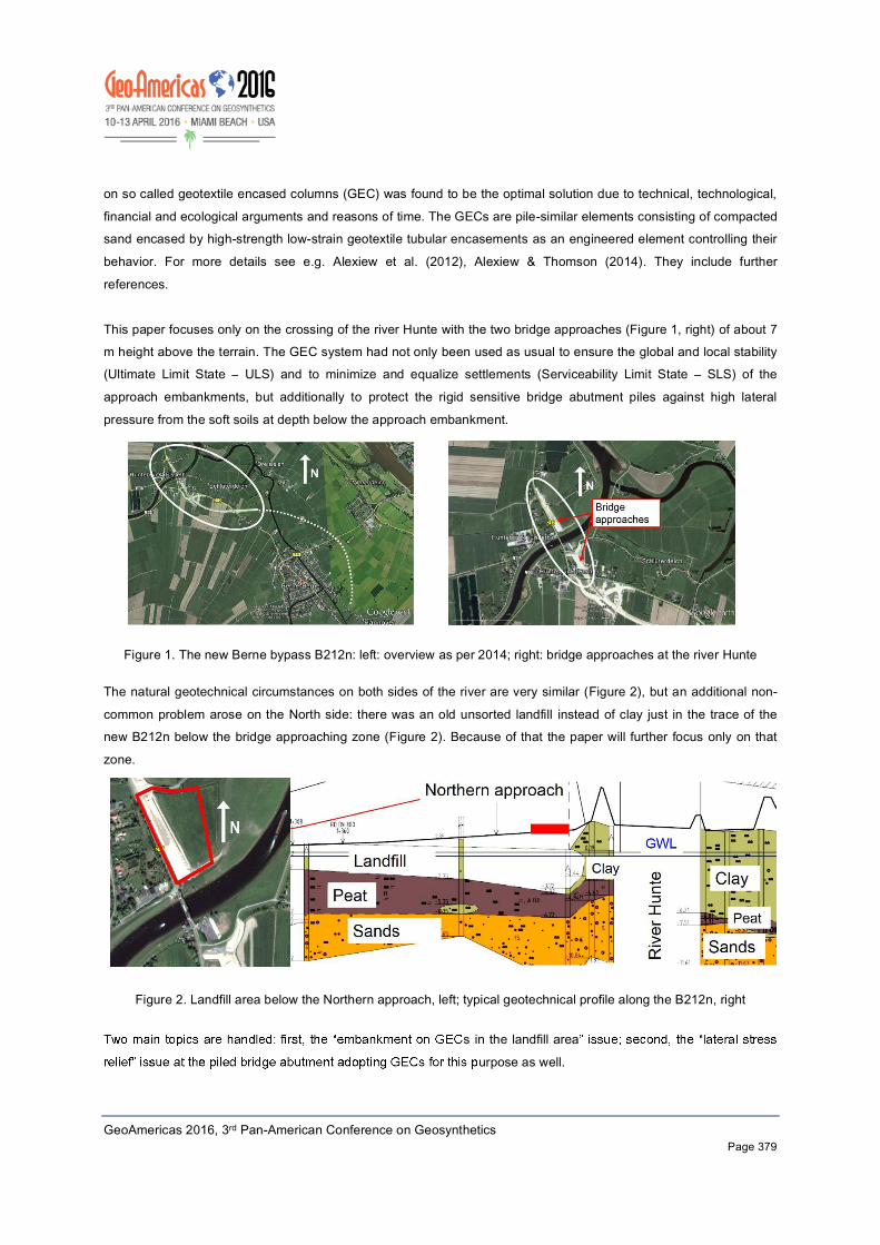
This paper focuses only on the crossing of the river Hunte with the two bridge approaches (Figure 1, right) of about 7 m height above the terrain. The GEC system had not only been used as usual to ensure the global and local stability (Ultimate Limit State ULS) and to minimize and equalize settlements (Serviceability Limit State SLS) of the
approach embankments, but additionally to protect the rigid sensitive bridge abutment piles against high lateral
pressure from the soft soils at depth below the approach embankment.
Figure 1. The new Berne bypass B212n: left: overview as per 2014; right: bridge approaches at the river Hunte
The natural geotechnical circumstances on both sides of the river are very similar (Figure 2), but an additional non-
common problem arose on the North side: there was an old unsorted landfill instead of clay just in the trace of the new B212n below the bridge approaching zone (Figure 2). Because of that the paper will further focus only on that
zone.
Figure 2. Landfill area below the Northern approach, left; typical geotechnical profile along the B212n, right
s in the landfill area
urpose as well.
GeoAmericas 2016, 3rd Pan-American Conference on Geosynthetics
2. GEOTECHNICAL OVERVIEW
The geotechnical situation below the Northern approach is depicted in a simplified way in Figure 2, right (to the left of the river Hunte in the Figure). Note that the picture is not to scale. The terrain is at ab 0.00
m is the average sea level). From top to bottom there is a thin artificial mixed fill cover layer (not shown), followed by
the unsorted waste of about 4 to 5 m thickness which had replaced over the years the natural clay (still existing on the South side of the river). The waste is underlaid by about 4 to 5 m of peat followed by the pleistocene sands. The
groundwater level (GWL in Figure 2, right) is at about mNN +-0.00 i.e. about 2 m below the natural terrain. It is under seasonal and tidal influence varying by about +-0.5 m, and is present also in the landfill. There is a second water horizon in the sand below the peat and clay (they act as hydraulic barriers) with some artesian pressure. The typical
geotechnical parameters of the materials are summarized in Table 1. Note that due to the significant local scattering
of the peat parameters some analyses were performed on the conservative side with
The waste in the landfill comprises an unsorted mixture not only of municipal waste (inclusive of e.g.
refrigerators and furniture), but also e.g. construction debris, used tires etc.
According to the German recommendations for landfills E 1-7, E 1-8 and E 2-19 (GDA Empfehlungen) geotechnical calculations can be performed handling waste as geotechnical material (soil), thus using e.g. classical methods as
Bishop or Janbu The waste parameters in Table 1 were assumed based on the German experience summarized in recommendation E 2-35 (GDA Empfehlungen) and
project experience. The values assumed are relatively conservative in terms of is below the GWL, see above and Figure 2, right.
3. THE
The existence of the waste below the Northern embankment was a significant technical and environmental problem
and challenge. To construct the embankment on top - - in combination with strong basal geosynthetic reinforcement (being under other circumstances a possible solution, see above) would take too long
consolidation time of some years; additionally, the heterogeneity of the waste could result in unpredictable absolute and differential settlements. During conceptual studies two options were primarily under consideration: first, to
excavate and re-dispose the waste replacing it by another homogeneous neutral fill; second, to construct
the approach as geogrid reinforced embankment on rigid piles installed through the waste and the peat down to the sands (Alexiew 2005). Due to financial, technical and ecological reasons and legal grounds the first option was
rejected soon. The second option appeared ecologically very risky due to the water paths at the interface pile/surrounding soil: that would result in hydraulic contact of the contaminated water inside the landfill to the clean
groundwater horizon in the sands below; either the contaminated water could infiltrate down or the artesian water could infiltrate up. Both phenomena have to be strictly avoided. Consequently, this option was rejected as well.
Consequently, at the end of the day at least one more appropriate feasible option had to be found.
GeoAmericas 2016, 3rd Pan-American Conference on Geosynthetics
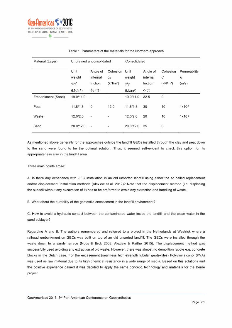
Table 1. Parameters of the materials for the Northern approach
Material (Layer) Undrained unconsolidated Consolidated
Unit weight
Angle of internal
friction
u
Cohesion cu
Unit weight
Angle of internal
friction
Cohesion
Permeability kf
(m/s)
Embankment (Sand) 19.0/11.0 - - 19.0/11.0 32.5 0
Peat 11.8/1.8 0 12.0 11.8/1.8 30 10 1x10⁻⁸
Waste 12.0/2.0 - - 12.0/2.0 20 10 1x10⁻⁶
Sand 20.0/12.0 - - 20.0/12.0 35 0
As mentioned above generally for the approaches outside the landfill GECs installed through the clay and peat down
to the sand were found to be the optimal solution. Thus, it seemed self-evident to check this option for its appropriateness also in the landfill area.
Three main points arose:
A. Is there any experience with GEC installation in an old unsorted landfill using either the so called replacement
and/or displacement installation methods (Alexiew et al. 2012)? Note that the displacement method (i.e. displacing the subsoil without any excavation of it) has to be preferred to avoid any extraction and handling of waste.
B. What about the durability of the geotextile encasement in the landfill environment? C. How to avoid a hydraulic contact between the contaminated water inside the landfill and the clean water in the
sand sublayer?
Regarding A and B: The authors remembered and referred to a project in the Netherlands at Westrick where a
railroad embankment on GECs was built on top of an old unsorted landfill. The GECs were installed through the waste down to a sandy terrace (Nods & Brok 2003, Alexiew & Raithel 2015). The displacement method was
successfully used avoiding any extraction of old waste. However, there was almost no demolition rubble e.g. concrete blocks in the Dutch case. For the encasement (seamless high-strength tubular geotextiles) Polyvinylalcohol (PVA)
was used as raw material due to its high chemical resistance in a wide range of media. Based on this solutions and the positive experience gained it was decided to apply the same concept, technology and materials for the Berne
project.
GeoAmericas 2016, 3rd Pan-American Conference on Geosynthetics
Regarding C: There had been other projects in Northern Germany with embankments on GECs where their toes
entered by typically 0.5 m sand layers under artesian pressure like herein at Berne. The hydraulic contact had been successfully blocked using in the last 1 m in the toe of GEC a sand-bentonite mixture of low permeability .
Note that also no water paths at the interface GEC to soils were registered. A possible explanation is the presence of
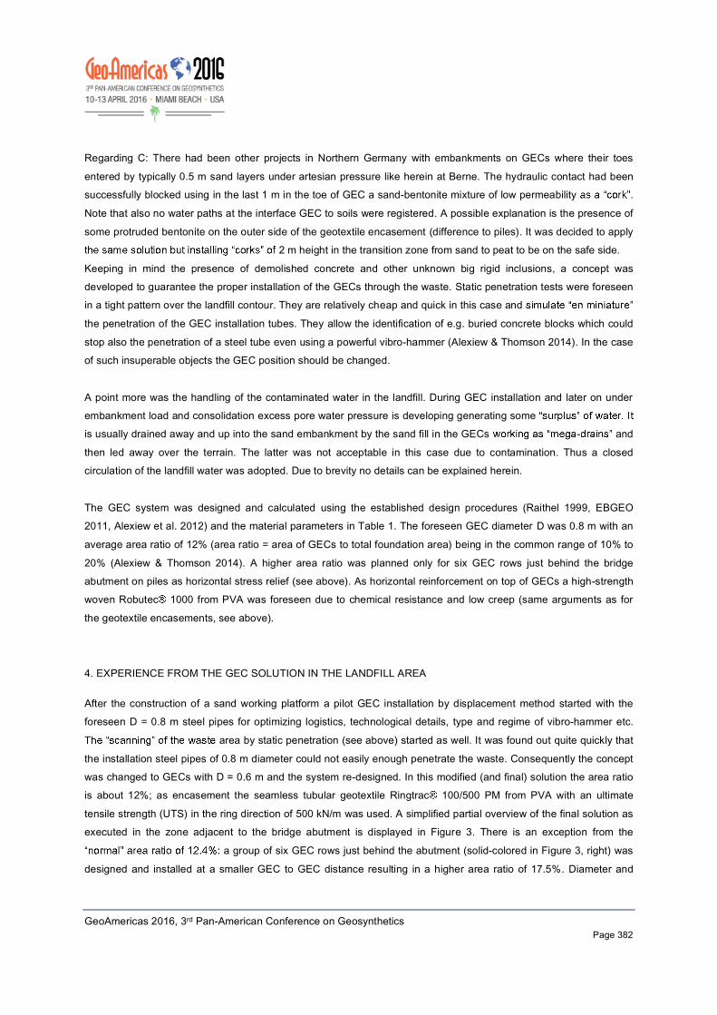
some protruded bentonite on the outer side of the geotextile encasement (difference to piles). It was decided to apply 2 m height in the transition zone from sand to peat to be on the safe side.
Keeping in mind the presence of demolished concrete and other unknown big rigid inclusions, a concept was developed to guarantee the proper installation of the GECs through the waste. Static penetration tests were foreseen in a tight pattern over the landfill contour. They are relatively cheap and quick in this case and
the penetration of the GEC installation tubes. They allow the identification of e.g. buried concrete blocks which could
stop also the penetration of a steel tube even using a powerful vibro-hammer (Alexiew & Thomson 2014). In the case of such insuperable objects the GEC position should be changed.
A point more was the handling of the contaminated water in the landfill. During GEC installation and later on under embankment load and consolidation excess pore water pressure is developing generating some is usually drained away and up into the sand embankment by the sand fill in the GECs - and
then led away over the terrain. The latter was not acceptable in this case due to contamination. Thus a closed circulation of the landfill water was adopted. Due to brevity no details can be explained herein.
The GEC system was designed and calculated using the established design procedures (Raithel 1999, EBGEO 2011, Alexiew et al. 2012) and the material parameters in Table 1. The foreseen GEC diameter D was 0.8 m with an
average area ratio of 12% (area ratio = area of GECs to total foundation area) being in the common range of 10% to
20% (Alexiew & Thomson 2014). A higher area ratio was planned only for six GEC rows just behind the bridge abutment on piles as horizontal stress relief (see above). As horizontal reinforcement on top of GECs a high-strength woven Robutec 1000 from PVA was foreseen due to chemical resistance and low creep (same arguments as for
the geotextile encasements, see above).
4. EXPERIENCE FROM THE GEC SOLUTION IN THE LANDFILL AREA
After the construction of a sand working platform a pilot GEC installation by displacement method started with the foreseen D = 0.8 m steel pipes for optimizing logistics, technological details, type and regime of vibro-hammer etc.
area by static penetration (see above) started as well. It was found out quite quickly that
the installation steel pipes of 0.8 m diameter could not easily enough penetrate the waste. Consequently the concept was changed to GECs with D = 0.6 m and the system re-designed. In this modified (and final) solution the area ratio is about 12%; as encasement the seamless tubular geotextile Ringtrac 100/500 PM from PVA with an ultimate
tensile strength (UTS) in the ring direction of 500 kN/m was used. A simplified partial overview of the final solution as executed in the zone adjacent to the bridge abutment is displayed in Figure 3. There is an exception from the
a group of six GEC rows just behind the abutment (solid-colored in Figure 3, right) was
designed and installed at a smaller GEC to GEC distance resulting in a higher area ratio of 17.5%. Diameter and
GeoAmericas 2016, 3rd Pan-American Conference on Geosynthetics
piles of the abutment (stress relief, see above and details in Chapter 5).
Generally the installation with the D = 0.6 m pipes was unproblematic and efficient, and the productivity was in the
common range. However, for about 5% of the GECs in the landfill the position had to be changed, usually by 0.3 to 0.5 m, e.g. when an adjacent static penetration indicated an insuperable (inpenetrable) object before reaching the
project depth. In some cases despite the tight pattern of - static penetrations a running GEC installation had to be stopped and the position changed. The strong horizontal reinforcement mentioned above is able to compensate and redistribute these position deviations. Due to brevity no further details can be reported herein.
Figure 3. Simplified overview of the GEC foundation adjacent to the Northern bridge abutment; all dimensions in meters; mNN means height above mean sea level in meters
An automated measurement program was applied inclusive of automatic settlement gauges (SG), piezometers (P) and earth pressure cells (EPC). A specific point is the installation of EPCs for registration of the total horizontal
normal stresses in the zone just behind and below the bridge abutment. Their axis and positions are depicted in Figure 3.
GeoAmericas 2016, 3rd Pan-American Conference on Geosynthetics
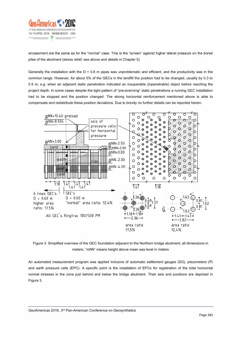
Figure 4 displays typical settlements in the landfill zone approximately in the embankment axis about 12 m behind the
bridge abutment, say completely over waste and peat (see Figure 2, right & Figure3, left). They were measured using automatic SGs. The settlements are generally quite small. They reflect quickly the changes in embankment height,
routine with GEC foundation (Alexiew & Raithel 2015). Some additional
settlements occur under constant load. They are relatively larger in the early stages of construction - despite the lower load - then later (compare e.g. months 2 to 6 with the time after month 25). Note that between the
25th and the 42nd month (in 17 months) the settlement increases only by 3.5 cm reaching its final value; no more settlement (e.g. due to creep) takes place after that. Analogues results were gained also using simple settlement plate gauges at regular intervals over the entire approach embankment axis (not shown herein).
It is worth keeping this in mind because of the specific presence of unsorted mixed waste as foundation soil and also of peat (generally tending to creep under load). Note that a strong secondary
settlement reduction although not down to zero as here - using GECs has been identified in many other cases as
well (Alexiew et al. 2012, Alexiew & Raithel 2015).
embankment on
A GEC foundation system can be used in an unsorted mixed landfill including also e.g. construction debris. The displacement method of installation can be adopted avoiding any waste excavation.
GEC diameter of max 0.6 m is recommended if large demolished concrete is expected.
- ation is recommended if huge inclusions or debris are expected. The use of PVA for the GEC-encasements and the horizontal reinforcement on top of them solves the
durability issue.
Contact of contaminated (landfill) and clean water can be avoided.
circuit.
A proper strong horizontal reinforcement can neutralize the effect of GEC-repositioning if needed.
Figure 4. Embankment height and typical settlements in the landfill area vs. time
GeoAmericas 2016, 3rd Pan-American Conference on Geosynthetics
5.
Lateral pressure at depth (horizontal normal stress h) generated in soft subsoil by surface loads (e.g. embankments)
can endanger adjacent rigid piles causing significant additional shear forces and bending moments. There are two possible ways to solve the problem. First, using more flexible insensitive supporting elements e.g. GECs instead of
common piles. This option was adopted e.g. for the stacker/reclaimer runways in a stockyard in Brazil (Alexiew et al.
2009). The second way is to reduce sufficiently h below the loaded area by technical measures e.g. also using
GECs. This option was chosen at the same time for both a project in Brazil (Schnaid et al. 2014) and behind the
bridge abutments in this project. le (2007) comprise a simplified procedure to judge when a pile
group is not endangered by lateral pressure from an adjacent embankment. The requirement is that the factor of
safety (FOS) for the global (external) stability of the embankment in direction to the piles is at least 1.4. A global stability analyses according to EBGEO (2011) was performed resulting in the GEC group shown solid-colored in Figure 3, right. The same type of columns and geotextile encasement were kept e
rest of approach embankment, only the number of GEC rows and the area ratio were increased until reaching a FOS
> 1.4. The result is six GEC rows and an area ratio of 17.5% (Figure 3).
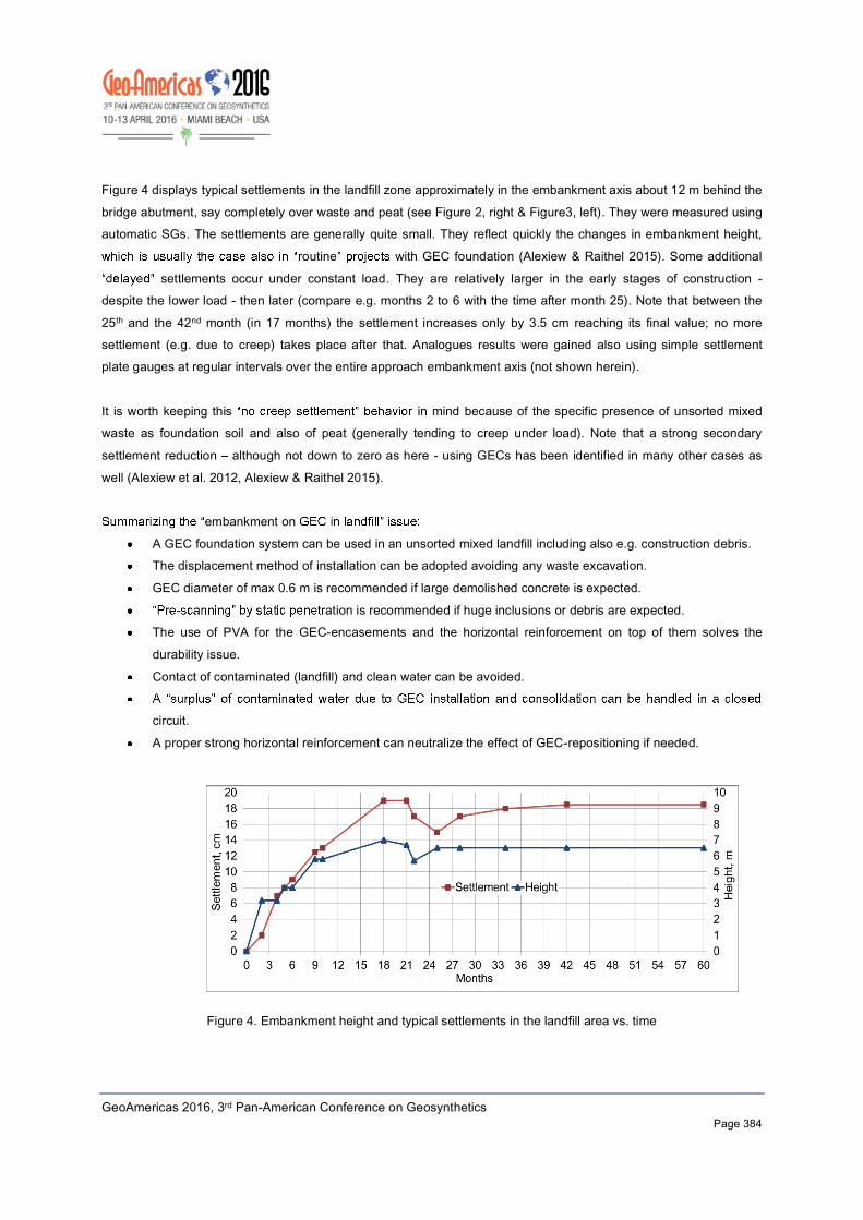
Additionally, based on regional experience, it was decided to limit the total h to maximum . A simplified
analysis was performed also in this regard confirming the solution explained above. Note that due to the lack of space all design analyses details, results and comparisons cannot be reported herein and will be published separately. To gain useful information on the appropriateness of GECs for lateral stress relief and also to control the upper limit
EPCs for total stress measurement were installed. Their positions are depicted in Figure 3. The EPCs were chosen in a way to allow for measurements in the sand fill (mNN +2.50), in the waste (mNN +-0.00), in
the clay (mNN -2.00) and in the peat (mNN -4.00) (Figure 3).
Figure 5. Total horizontal stresses h at four levels in four different layers behind the bridge abutment over time (see
also Figure 3)
GeoAmericas 2016, 3rd Pan-American Conference on Geosynthetics
A specific installation technique was applied to guarantee the correct total stress registration in all layers. In Figure 5
the total h development over time is displayed.
Note that because the sand fill at mNN+2.50 is quite above the average GWL at mNN+-0.00 (varying by about +-0.5
m) the total h is not influenced by the GWL changes, it undergoes less deviations and the h -graph is smoother in
contrast to the other lower levels/layers. It is by the way an indication of the proper installation and function of the
EPCs. It can be assumed that in this sand fill layer the registered h is not the total but rather the effective h .
From the practical point of view the most important fact is that the highest total h (as it has to be
expected in the clay) is less than the half of total h to be expected without the stress relief GEC group demonstrating
the correctness of design approach and the suitability of GECs as lateral pressure relief measure. The latter is also stated in Schnaid et al. (2014). The stress is also well below t .
Generally the total h of the clay and of the peat meets the expectations taking into account their position
and permeability (Figure 3 and Table 1). From special interest are the measurement results for the waste being something of a rarity and positioning its behavior between the behavior of the clay and of the peat. Due to lack of
space more detailed evaluations, analyses, comparisons and hypotheses will be presented later elsewhere.
6. SOME FINAL REMARKS
The new German Federal Highway B212n as a bypass of the City of Berne in Northern Germany is situated in a region well known for its soft soils and high ground water level. The B212n crosses the river Hunte, where high bridge
approach embankments became obligatory. As the optimal solution, a foundation on geotextile encased columns (GEC) was chosen.
There are two specific issues in connection with the some hundred meters long and about 7 m high Northern bridge
approach embankment: first, the GECs are positioned in an old unsorted mixed landfill this created significant
technical and ecological difficulties; second, a group of GECs has to work as horizontal stress (lateral pressure) relief in depth protecting the sensitive rigid piles of the bridge abutment.
Both issues were solved successfully. Philosophy, concepts, solutions, experience, measurements and lessons
learned inclusive of recommendations especially for the landfill problem are briefly presented.
Getting to the point: it is possible to cross a problematic landfill by GECs; it is possible to use GECs as stress relief system. The technique also seems to be highly adaptable to uncommon problems.
GeoAmericas 2016, 3rd Pan-American Conference on Geosynthetics
ACKNOWLEDGEMENTS
Many parties participated in this uncommon project: consultants, investors, officials and supervisors. Fortunately they
worked as a team despite many controversial discussions. The authors being only a part of this engineering constellation would like to express their appreciation to all participants for their efforts and acceptance of new
solutions.
REFERENCES
Alexiew, D. (2005). Piled embankments: Overview of methods and significant case studies ,
Osaka, pp 1819 1822. Alexiew, D., Moormann, C. and Jud, H. (2009). Foundations of a coal/coke stockyard on soft soil with geotextile
encased columns and horizontal reinforcement, , Alexandria, Egypt, pp. 2236-2239.
Alexiew, D. and Blume, K.-H. (2010). Two reinforced embankments on soft soils: Experience after more than twenty years, Guaruja, Brasil, pp. 1851 1854.
Alexiew, D. and Blume, K.-H. (2012). Motorway embankment in problematic coastal soft areas: Long-term
experience with the basal reinforcement, , ICGI, University of Wollongong, Australia, pp. 911-916.
and Detert, O. (2012). 15 years of experience with geotextile encased granular
columns as foundation systems, IS GI, Brussels, Belgium
Alexiew, D. and Thomson, G. (2014). Geotextile encased columns (GEC): Why, when, what, how? , Brisbane, Australia,
ISBN: 978-4-9905958-3-8 C 3051. pp. 484-489. Alexiew, D. and Raithel, M. (2015). Geotextile encased columns (GEC): Case studies over twenty years.
. , Elsevier, Buddhima Indraratna, Chu Jian, Editors (to be published). Blume, K.- many with high
geosynthetic reinforced embankments on soft soils
Yokohama, Japan, pp. 912-916. EA- , Ernst & Sohn, 2007.
EBGEO (2011). Recommendations for Design and Analysis of Earth Structures Using Geosynthetic Reinforcements. , Ernst & Sohn, Essen-Berlin, Germany.
GDA Empfehlungen E 1-7, E 1-8, E 2-19, E 2-35. , Essen, Germany. Nods, M. and Brok, C. (2003). Geotextiel ommantelde zandpalen als fundering voor HSL bij Prinsenbeek,
, pp. 80-83. Raithel, M. (1999). Zum Trag- ,
chule Kassel, Kassel, Germany.
Schnaid, F., Winter, D., Silva, A.E.F., Alexiew, D Geotextile Encased Columns (GEC) under bridge approaches as a pressure-relief system: Concept, experience, measurements,
Berlin, Germany, CD, no pages.