Embed Size (px)
Citation preview
Brickwork Arch Bridges
David Cox CEng, MICE, MIHT Richard Halsall CEng, MIStructE
May 1996
FCI/SfB182
Brickwork Arch Bridges
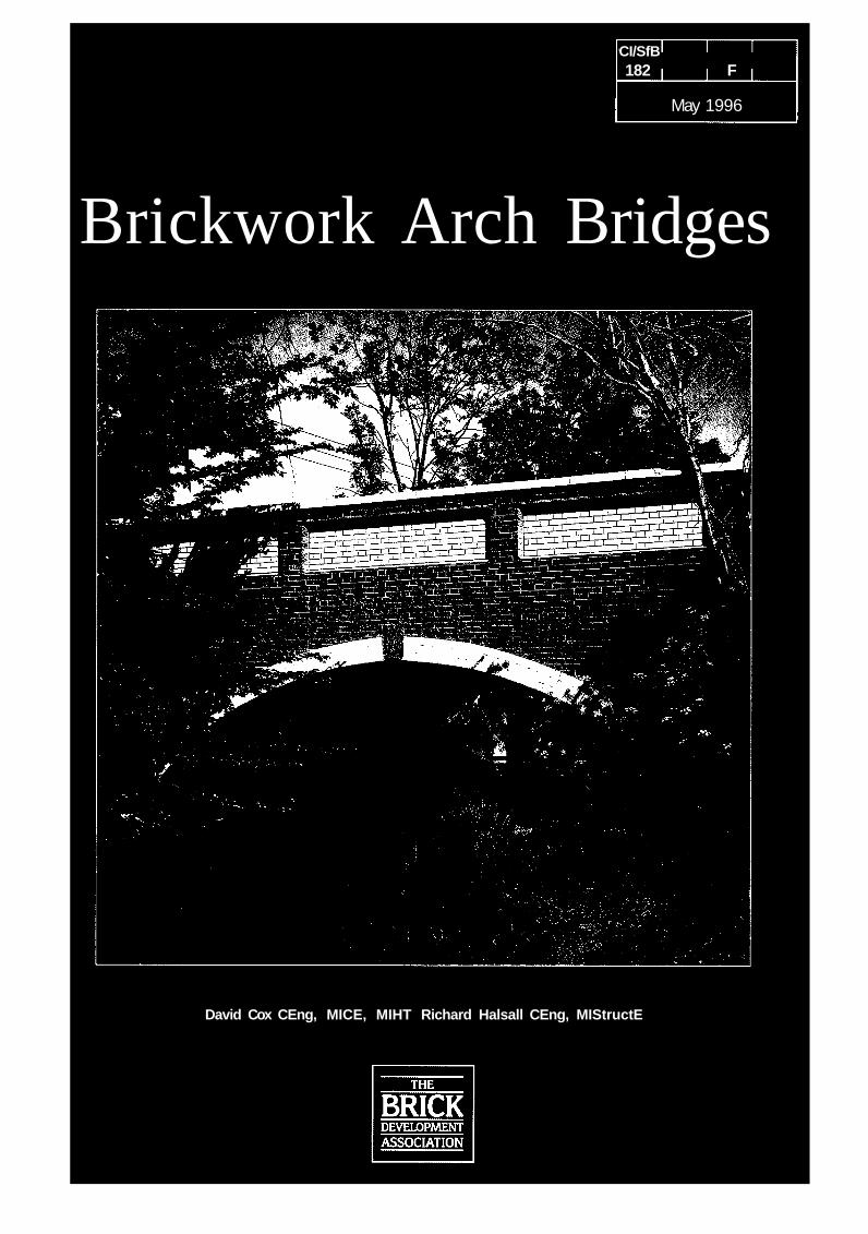
Contents
Introduction
Selection, form and suitability
General durability considerations
Foundations and abutments
Arch ring
Spandrel walls, wing walls and fill
Parapets
Brickwork designGeneral
Engineering performance
Durability
Mortars
Detailing
Movement accommodation
Competitiveness
Conclusions
References
4
5
6
6
7
8
9
10
10
10
11
11
11
12
13
13
14
AuthorsDavid Cox CEng, MICE, MIHT. Head of Bridges, WS Atkins Consultants Ltd, Cambridge.David Cox's career in highways and bridges with Cambridgeshire County Council included theaward winning Foxcovcrt Road and Railway Bridges and the cable stayed Cambridge StationCycleway Bridge. Reorganisation of the County's Transportation Department saw the formationof the Engineering Consultancy Division which in 1995 was transferred to WS AtkinsConsultants Ltd where he became Head of Bridges.
Richard Halsall CEng, MIStructE. County Bridge Engineer, Transportation Department,Cambridgeshire County Council.Richard Halsall has spent more than twenty years in bridge design and maintenance and hasbeen actively involved in the development and innovative use of brickwork in bridges, includingthe BDA award winning Foxcovert Road and Railway Bridges. He became CambridgeshireCounty Bridge Engineer, managing a stock of 2500 bridges, when the Transportation Departmentwas created.
Technical editor: John Page BSc.John Page worked at the Transport Research Laboratory until 1995, with responsibilitiesincluding its programme of research on masonry arch bridges. This included a load test onKimbolton Butts Bridge shortly after it was completed. He is the author of about sixty papers,including the TRL State of the Art Review Masonry Arch Bridges. He is now an independentconsultant.
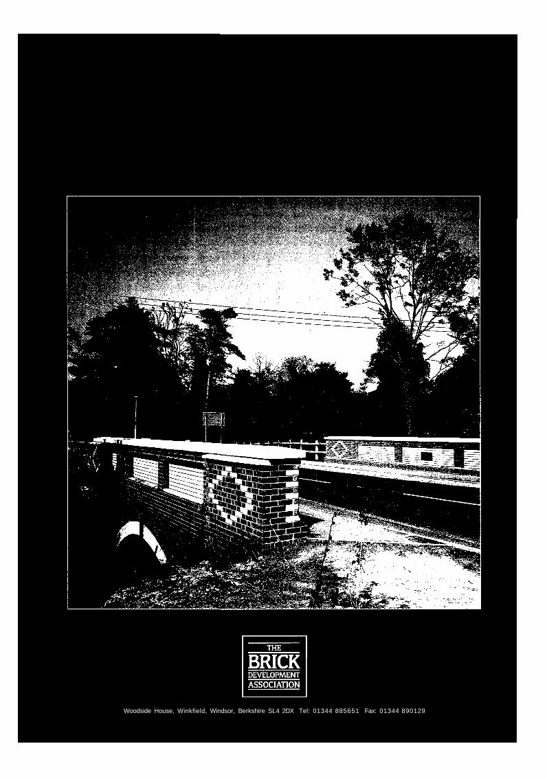
3Front and rear covers:Kimbolton Butts Bridge, Cambridgeshire.
Introduction
There are about one hundred thousand highway carryingbridges in the United Kingdom and about forty percentof them are brick or stone masonry arch bridges. Mostof these masonry arches were built in the eighteenth andnineteenth centuries during the construction of the canalsand railways. Very few have been built since the firstworld war when steel and concrete took over as theprincipal bridge construction materials.
A major programme of assessing the traffic load capacityof the UK highway bridge stock is currently underway inpreparation for the introduction of heavier commercialvehicles. This programme has shown that arch bridgesrequire less maintenance than steel and concrete bridgeswhich suffer from corrosion of steel (including steelreinforcement), and wear and tear to bearings andexpansion joints. Arch bridges do not contain theseitems. Despite being older and often carrying loadsmuch in excess of those envisaged when they were built,maintenance costs of masonry arch bridges are abouttwo thirds of those for comparable steel and concretebridges. They also make an attractive contribution tothe environment.
These factors, coupled with the need to provide a120 year design life, have led to a renewed interest inbuilding traditional unreinforced masonry arch bridges.Cambridgeshire County Council led the way in 1992by building Kimbolton Butts Bridge, illustrated on thecovers, which is thought to be the first completely newbrick arch highway bridge of traditional construction to
be built in the UK since before the second world war.The bridge replaced one of steel and concrete whichwas assessed to have inadequate load capacity and wasuneconomic to strengthen. It is located in a conservationarea and it was felt that the setting warranted anattractive bridge which would blend well with the localenvironment. The local residents were strongly in favourof a brick arch bridge. The construction cost was littlemore than that of a steel or concrete structure, andbecause of the low maintenance cost of masonryarch bridges, its estimated whole life cost was less.
The Department of Transport (DoT) supportedCambridgeshire County Council and is encouragingthe construction of new arch bridges. To further thisobjective, DoT is preparing a Design Standard andAdvice Note. The purpose of this BDA SpecialPublication is to give practical advice on brick archbridge design and is intended to be complementary tothe DoT documents. They will be referred to in thisPublication as the Design Standard and Advice Note.
The aim is to encourage the construction of new brickarch bridges which retain the longevity and lowmaintenance costs of traditional arch bridges, but whichmay incorporate modern techniques to help achieve thisand to meet the requirements of modern highway design.This Publication draws on other BDA publications,BSI Standards and DoT Standards and they should bereferred to for more detailed information; they are listedin the References, on page 14.
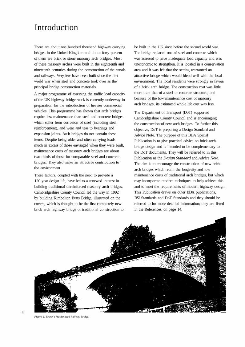
Figure 1. Brunel's Maidenhead Railway Bridge.4
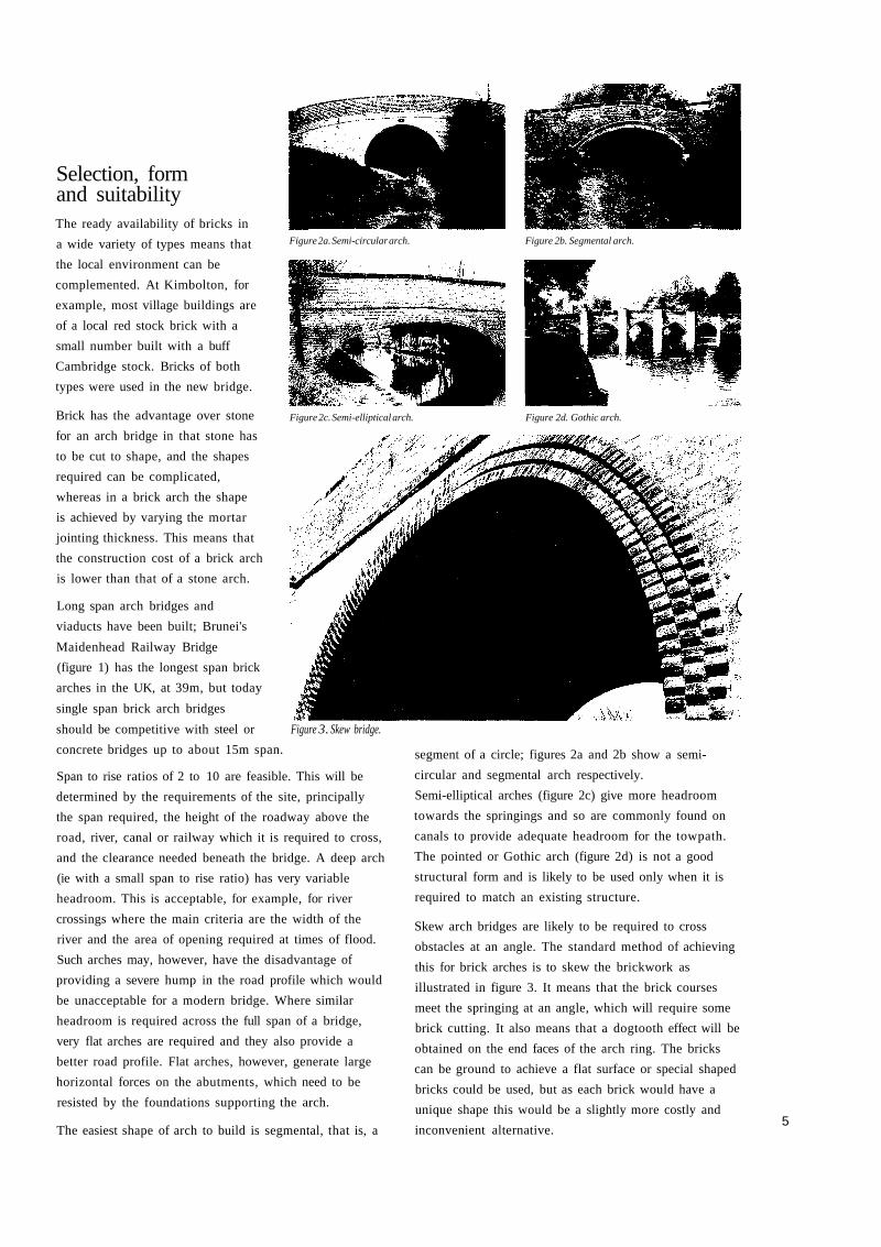
Figure 2a. Semi-circular arch.
Figure 2c. Semi-elliptical arch.
Selection, formand suitabilityThe ready availability of bricks in
a wide variety of types means that
the local environment can be
complemented. At Kimbolton, for
example, most village buildings are
of a local red stock brick with a
small number built with a buff
Cambridge stock. Bricks of both
types were used in the new bridge.
Brick has the advantage over stone
for an arch bridge in that stone has
to be cut to shape, and the shapes
required can be complicated,
whereas in a brick arch the shape
is achieved by varying the mortar
jointing thickness. This means that
the construction cost of a brick arch
is lower than that of a stone arch.
Long span arch bridges and
viaducts have been built; Brunei's
Maidenhead Railway Bridge
(figure 1) has the longest span brick
arches in the UK, at 39m, but today
single span brick arch bridges
should be competitive with steel or Figure 3. Skew bridge.
concrete bridges up to about 15m span.
Span to rise ratios of 2 to 10 are feasible. This will be
determined by the requirements of the site, principally
the span required, the height of the roadway above the
road, river, canal or railway which it is required to cross,
and the clearance needed beneath the bridge. A deep arch
(ie with a small span to rise ratio) has very variable
headroom. This is acceptable, for example, for river
crossings where the main criteria are the width of the
river and the area of opening required at times of flood.
Such arches may, however, have the disadvantage of
providing a severe hump in the road profile which would
be unacceptable for a modern bridge. Where similar
headroom is required across the full span of a bridge,
very flat arches are required and they also provide a
better road profile. Flat arches, however, generate large
horizontal forces on the abutments, which need to be
resisted by the foundations supporting the arch.
The easiest shape of arch to build is segmental, that is, a
Figure 2b. Segmental arch.
Figure 2d. Gothic arch.
segment of a circle; figures 2a and 2b show a semi-
circular and segmental arch respectively.
Semi-elliptical arches (figure 2c) give more headroom
towards the springings and so are commonly found on
canals to provide adequate headroom for the towpath.
The pointed or Gothic arch (figure 2d) is not a good
structural form and is likely to be used only when it is
required to match an existing structure.
Skew arch bridges are likely to be required to cross
obstacles at an angle. The standard method of achieving
this for brick arches is to skew the brickwork as
illustrated in figure 3. It means that the brick courses
meet the springing at an angle, which will require some
brick cutting. It also means that a dogtooth effect will be
obtained on the end faces of the arch ring. The bricks
can be ground to achieve a flat surface or special shaped
bricks could be used, but as each brick would have a
unique shape this would be a slightly more costly and
inconvenient alternative.5
General durability considerationsArch bridges are exposed structures and so many of thepotential durability concerns are due to the effects ofwater - either rainwater, floodwater, groundwater, orwater from burst pipes within the structure. Water willwash out fines from the fill, chemicals dissolved in thewater may react with the mortar, or damage tobrickwork may occur due to cycles of freezing andthawing. Bricks with improved and more consistentproperties are now available than when most existingarch bridges were built. Nevertheless, it is important forthe longevity of the bridge to protect the brickwork fromwater as far as possible. This can be achieved in thefollowing ways:
• The bridge deck should be well drained and made aswaterproof as possible so that little surface water getsinto the structure. Water which does penetrate shouldbe able to flow readily down through the structure
to adequate and easily maintained drains whichremove it.
• Faces in contact with fill, that is, the extrados of thearch ring and the back face of the spandrel and wingwalls, should be waterproofed.
• Selection of brickwork should be appropriate to the
position in the structure, exposure situation and
constructional detailing used.
• Parapets should preferably have an adequate coping,with associated damp-proof course system, to throwrainwater clear of the outside faces of the bridge.If a flush capping is used (which will not protectbrickwork from saturation), the brickwork must beof suitable frost resistant construction.
• If steel reinforcement is used in the structure, it shouldbe of a suitable type to resist corrosion or beadequately protected. Where post-tensioning is used,the steel should be designed to be replaceable duringthe working life of the structure.
Some of these aspects are discussed in moredetail later.
Foundations and abutmentsMany existing arch bridges have foundations that wouldbe deemed inadequate using modern design standards;they survive because the arch ring is an inherentlyflexible structure and can endure some movementwithout undue distress. However, foundation design for anew arch bridge should be based on the same principlesas for any other new bridge. The aim is to support thedead loads applied by the bridge superstructure,including the thrust of the arch ring, and the loadsgenerated by traffic etc, such that movements are smallenough not to cause serviceability or ultimate limit state
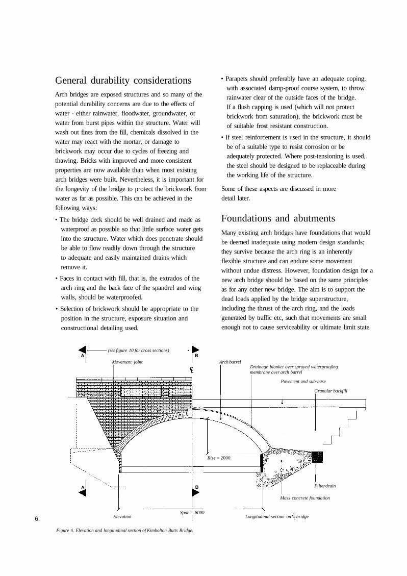
Drainage blanket over sprayed waterproofingmembrane over arch barrel
Pavement and sub-base
Granular backfill
Filter drain
Mass concrete foundation
Span = 8000Elevation
Figure 4. Elevation and longitudinal section of Kimbolton Butts Bridge.
Longitudinal section on
(see figure 10 for cross sections)A
Movement jointB
Arch barrel
Rise = 2000
bridge6
A B
Figure 5.Foundation /springing.
failures of the arch ring. Conventional reinforced
concrete mass foundations should be used if possible;
the alternative use of piled foundations will increase the
construction cost of the bridge by about 20%. Figures 4
and 5 show the mass concrete foundation and abutment
design used for Kimbolton Butts Bridge. For continuity
of appearance, the abutment wall should be of brick.
It can be a non-loadbearing skin but it is preferable to
make it part of the loadbearing structure, tied in to
concrete backing.
The DoT Advice Note will give guidance on
abutment sizes.
If the bridge crosses a river, the design should also take
into consideration hydraulic effects; DoT document
BA 59 gives advice on this aspect.
Arch ringInitial sizing of the arch ring may be done using
empirical methods: advice will be found in the DoT
Advice Note. For Kimbolton Butts Bridge the MEXE
method (DoT et ah BD 21 and BA 16) was used.
The design may then be refined using a variety of
analytical methods which can be categorised as:
• elastic methods.
• plastic (or mechanism) methods.
• numerical methods (eg, finite elements).
All these methods are available as commercial computer
software packages. Most methods permit the fill to
behave structurally, that is, it will disperse wheel loads
from the road surface onto the arch ring, and it will
resist movement of the arch ring by the development of
passive pressures.
Where mortar pointing is used as the method of joint
finishing, the pointing depth should not be relied upon to
carry dead load stresses. For structural design purposes
it is advisable to reduce the chosen arch ring thickness
by about 25mm and this will take account of mortar
pointing and also the likely need to repoint mortar
joints during the working life of the bridge.
Brick arch bridges were commonly built with multiple
rings of brick, with the rings bonded only by mortar.
Ring separation is a common feature of these bridges,
with the mortar in between rings having deteriorated due
either to the applied loading or to chemical attack on the
mortar, or a combination of these factors. It is possible
to design against this occurring by bonding the arch
brickwork through the depth of the ring. Bonding of
each row of bricks transversely is also necessary.
Possible bonds may be as follows:
• A ring 215mm thick can be obtained by laying all the
bricks as headers (figure 6a). Alternatively an English
bond could be used so that half the bricks are headers
and half stretchers, to give better transverse bonding
(figure 6b). This ring thickness could be used up to a
maximum span of about 4m.
Figure 6a. Extrados
Intrados
Figure 6b. Extrados
Intrados
Figure 6. Arch ring bonds.7
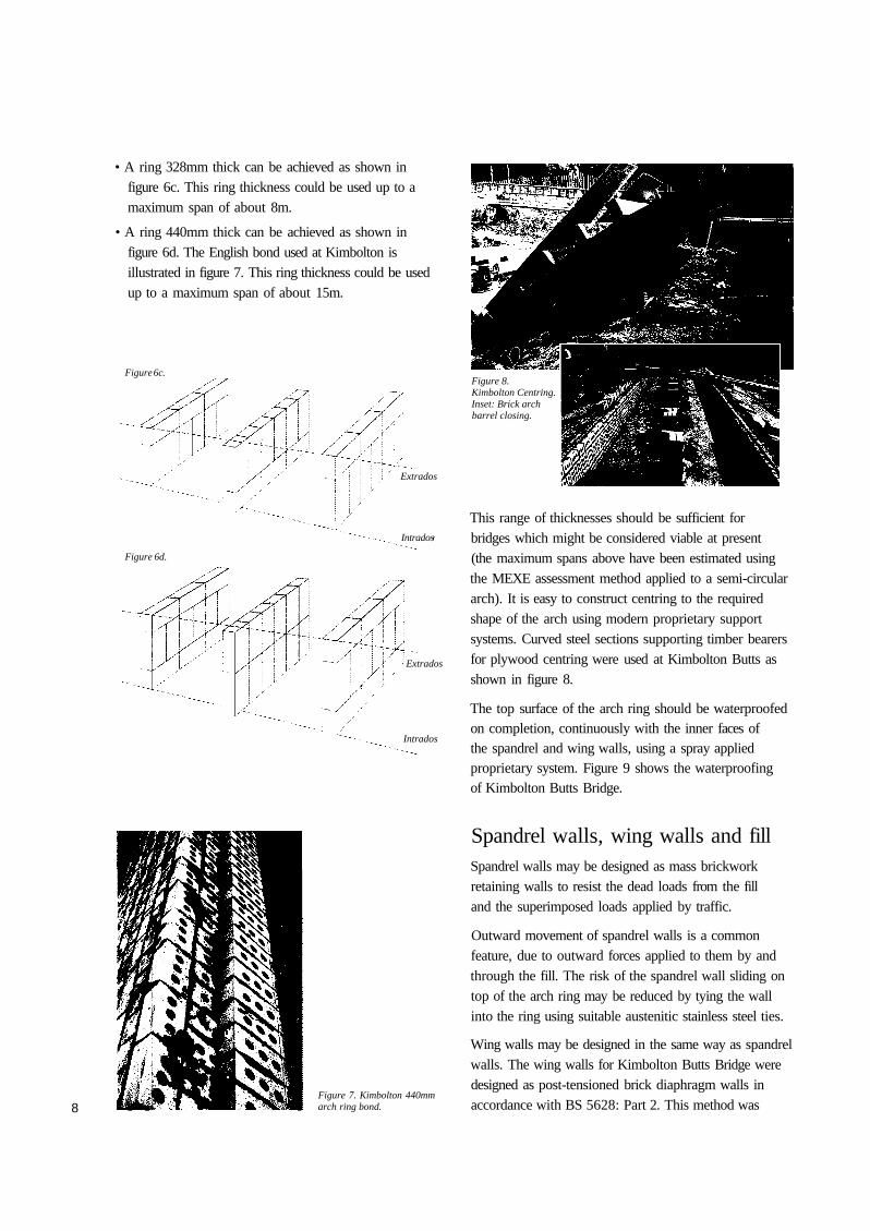
• A ring 328mm thick can be achieved as shown infigure 6c. This ring thickness could be used up to amaximum span of about 8m.
• A ring 440mm thick can be achieved as shown infigure 6d. The English bond used at Kimbolton isillustrated in figure 7. This ring thickness could be usedup to a maximum span of about 15m.
Figure 6c.
Extrados
Intrados
Figure 6d.
Intrados
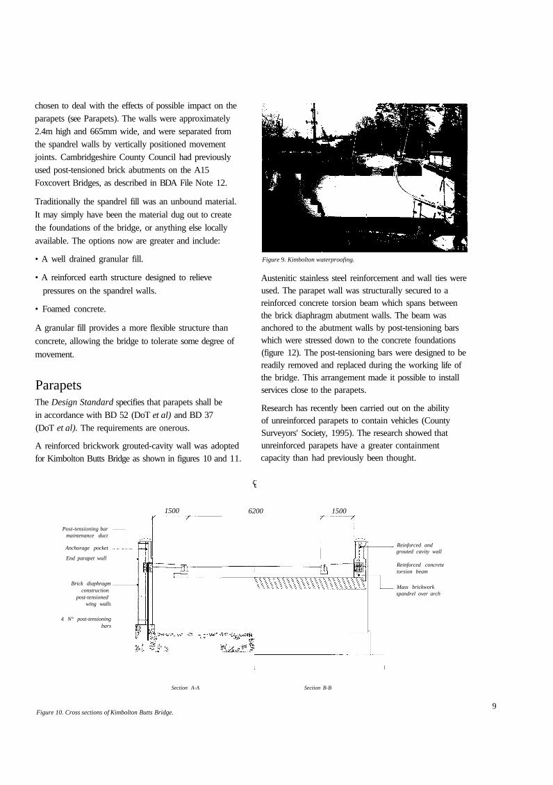
Figure 8.Kimbolton Centring.Inset: Brick archbarrel closing.
This range of thicknesses should be sufficient forbridges which might be considered viable at present(the maximum spans above have been estimated usingthe MEXE assessment method applied to a semi-circulararch). It is easy to construct centring to the requiredshape of the arch using modern proprietary supportsystems. Curved steel sections supporting timber bearersfor plywood centring were used at Kimbolton Butts asshown in figure 8.
The top surface of the arch ring should be waterproofedon completion, continuously with the inner faces ofthe spandrel and wing walls, using a spray appliedproprietary system. Figure 9 shows the waterproofingof Kimbolton Butts Bridge.
Figure 7. Kimbolton 440mmarch ring bond.
Spandrel walls, wing walls and fillSpandrel walls may be designed as mass brickworkretaining walls to resist the dead loads from the filland the superimposed loads applied by traffic.
Outward movement of spandrel walls is a commonfeature, due to outward forces applied to them by andthrough the fill. The risk of the spandrel wall sliding ontop of the arch ring may be reduced by tying the wallinto the ring using suitable austenitic stainless steel ties.
Wing walls may be designed in the same way as spandrelwalls. The wing walls for Kimbolton Butts Bridge weredesigned as post-tensioned brick diaphragm walls inaccordance with BS 5628: Part 2. This method was
Extrados
8
chosen to deal with the effects of possible impact on theparapets (see Parapets). The walls were approximately2.4m high and 665mm wide, and were separated fromthe spandrel walls by vertically positioned movementjoints. Cambridgeshire County Council had previouslyused post-tensioned brick abutments on the A15Foxcovert Bridges, as described in BDA File Note 12.
Traditionally the spandrel fill was an unbound material.
It may simply have been the material dug out to create
the foundations of the bridge, or anything else locally
available. The options now are greater and include:
• A well drained granular fill.
• A reinforced earth structure designed to relieve
pressures on the spandrel walls.
• Foamed concrete.
A granular fill provides a more flexible structure than
concrete, allowing the bridge to tolerate some degree of
movement.
ParapetsThe Design Standard specifies that parapets shall bein accordance with BD 52 (DoT et al) and BD 37(DoT et al). The requirements are onerous.
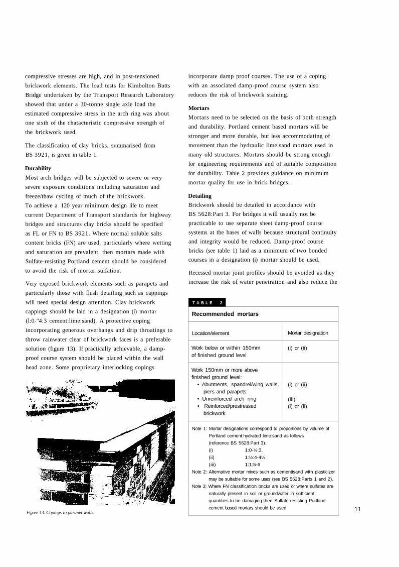
A reinforced brickwork grouted-cavity wall was adoptedfor Kimbolton Butts Bridge as shown in figures 10 and 11.
Figure 9. Kimbolton waterproofing.
Austenitic stainless steel reinforcement and wall ties wereused. The parapet wall was structurally secured to areinforced concrete torsion beam which spans betweenthe brick diaphragm abutment walls. The beam wasanchored to the abutment walls by post-tensioning barswhich were stressed down to the concrete foundations(figure 12). The post-tensioning bars were designed to bereadily removed and replaced during the working life ofthe bridge. This arrangement made it possible to installservices close to the parapets.
Research has recently been carried out on the abilityof unreinforced parapets to contain vehicles (CountySurveyors' Society, 1995). The research showed thatunreinforced parapets have a greater containmentcapacity than had previously been thought.
Post-tensioning barmaintenance duct
Anchorage pocket
End parapet wall
Brick diaphragmconstruction
post-tensionedwing walls
4 N° post-tensioningbars
6200
Reinforced andgrouted cavity wall
Reinforced concretetorsion beam
Mass brickworkspandrel over arch
Figure 10. Cross sections of Kimbolton Butts Bridge.
1500 1500
Section A-A Section B-B
9
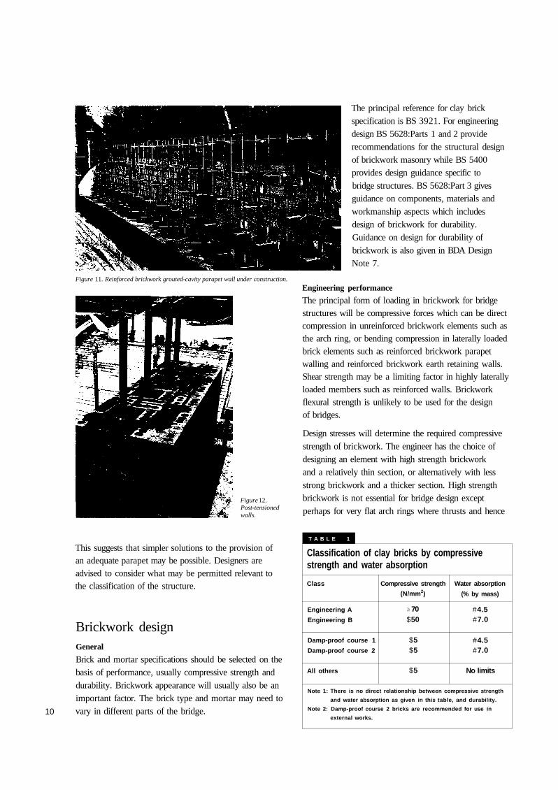
Figure 11. Reinforced brickwork grouted-cavity parapet wall under construction.
Figure 12.Post-tensionedwalls.
This suggests that simpler solutions to the provision ofan adequate parapet may be possible. Designers areadvised to consider what may be permitted relevant tothe classification of the structure.
Brickwork design
10
General
Brick and mortar specifications should be selected on thebasis of performance, usually compressive strength anddurability. Brickwork appearance will usually also be animportant factor. The brick type and mortar may need tovary in different parts of the bridge.
The principal reference for clay brickspecification is BS 3921. For engineeringdesign BS 5628:Parts 1 and 2 providerecommendations for the structural designof brickwork masonry while BS 5400provides design guidance specific tobridge structures. BS 5628:Part 3 givesguidance on components, materials andworkmanship aspects which includesdesign of brickwork for durability.Guidance on design for durability ofbrickwork is also given in BDA DesignNote 7.
Engineering performance
The principal form of loading in brickwork for bridgestructures will be compressive forces which can be directcompression in unreinforced brickwork elements such asthe arch ring, or bending compression in laterally loadedbrick elements such as reinforced brickwork parapetwalling and reinforced brickwork earth retaining walls.Shear strength may be a limiting factor in highly laterallyloaded members such as reinforced walls. Brickworkflexural strength is unlikely to be used for the designof bridges.
Design stresses will determine the required compressivestrength of brickwork. The engineer has the choice ofdesigning an element with high strength brickworkand a relatively thin section, or alternatively with lessstrong brickwork and a thicker section. High strengthbrickwork is not essential for bridge design exceptperhaps for very flat arch rings where thrusts and hence
Classification of clay bricks by compressivestrength and water absorption
Class
Engineering A
Engineering B
Damp-proof course 1
Damp-proof course 2
All others
(N/mm2)
$50
$5$5
$5
(% by mass)
#4.5#7.0
#4.5#7.0
No limits
Note 1: There is no direct relationship between compressive strength
and water absorption as given in this table, and durability.
Note 2: Damp-proof course 2 bricks are recommended for use in
external works.
T A B L E 1
Compressive strength
70
Water absorption
$
compressive stresses are high, and in post-tensioned
brickwork elements. The load tests for Kimbolton Butts
Bridge undertaken by the Transport Research Laboratory
showed that under a 30-tonne single axle load the
estimated compressive stress in the arch ring was about
one sixth of the chatacteristic compressive strength of
the brickwork used.
The classification of clay bricks, summarised from
BS 3921, is given in table 1.
Durability
Most arch bridges will be subjected to severe or very
severe exposure conditions including saturation and
freeze/thaw cycling of much of the brickwork.
To achieve a 120 year minimum design life to meet
current Department of Transport standards for highway
bridges and structures clay bricks should be specified
as FL or FN to BS 3921. Where normal soluble salts
content bricks (FN) are used, particularly where wetting
and saturation are prevalent, then mortars made with
Sulfate-resisting Portland cement should be considered
to avoid the risk of mortar sulfation.
Very exposed brickwork elements such as parapets and
particularly those with flush detailing such as cappings
will need special design attention. Clay brickwork
cappings should be laid in a designation (i) mortar
(l:0-''4:3 cement:lime:sand). A protective coping
incorporating generous overhangs and drip throatings to
throw rainwater clear of brickwork faces is a preferable
solution (figure 13). If practically achievable, a damp-
proof course system should be placed within the wall
head zone. Some proprietary interlocking copings
incorporate damp proof courses. The use of a coping
with an associated damp-proof course system also
reduces the risk of brickwork staining.
Mortars
Mortars need to be selected on the basis of both strength
and durability. Portland cement based mortars will be
stronger and more durable, but less accommodating of
movement than the hydraulic lime:sand mortars used in
many old structures. Mortars should be strong enough
for engineering requirements and of suitable composition
for durability. Table 2 provides guidance on minimum
mortar quality for use in brick bridges.
Detailing
Brickwork should be detailed in accordance with
BS 5628:Part 3. For bridges it will usually not be
practicable to use separate sheet damp-proof course
systems at the bases of walls because structural continuity
and integrity would be reduced. Damp-proof course
bricks (see table 1) laid as a minimum of two bonded
courses in a designation (i) mortar should be used.
Recessed mortar joint profiles should be avoided as they
increase the risk of water penetration and also reduce the
Figure 13. Copings to parapet walls.
Recommended mortars
Location/element
Work below or within 150mmof finished ground level
Work 150mm or more abovefinished ground level:
• Abutments, spandrel/wing walls,piers and parapets
• Unreinforced arch ring• Reinforced/prestressed
brickwork
Mortar designation
(i) or (ii)
(i) or (ii)
(iii)(i) or (ii)
Note 1: Mortar designations correspond to proportions by volume of
Portland cement:hydrated lime:sand as follows
(reference BS 5628:Part 3):
(i) 1:0-¼:3.
(ii) 1:½:4-4½
(iii) 1:1:5-6
Note 2: Alternative mortar mixes such as cementisand with plasticizer
may be suitable for some uses (see BS 5628:Parts 1 and 2).
Note 3: Where FN classification bricks are used or where sulfates are
naturally present in soil or groundwater in sufficient
quantities to be damaging then Sulfate-resisting Portland
cement based mortars should be used. 11
T A B L E 2
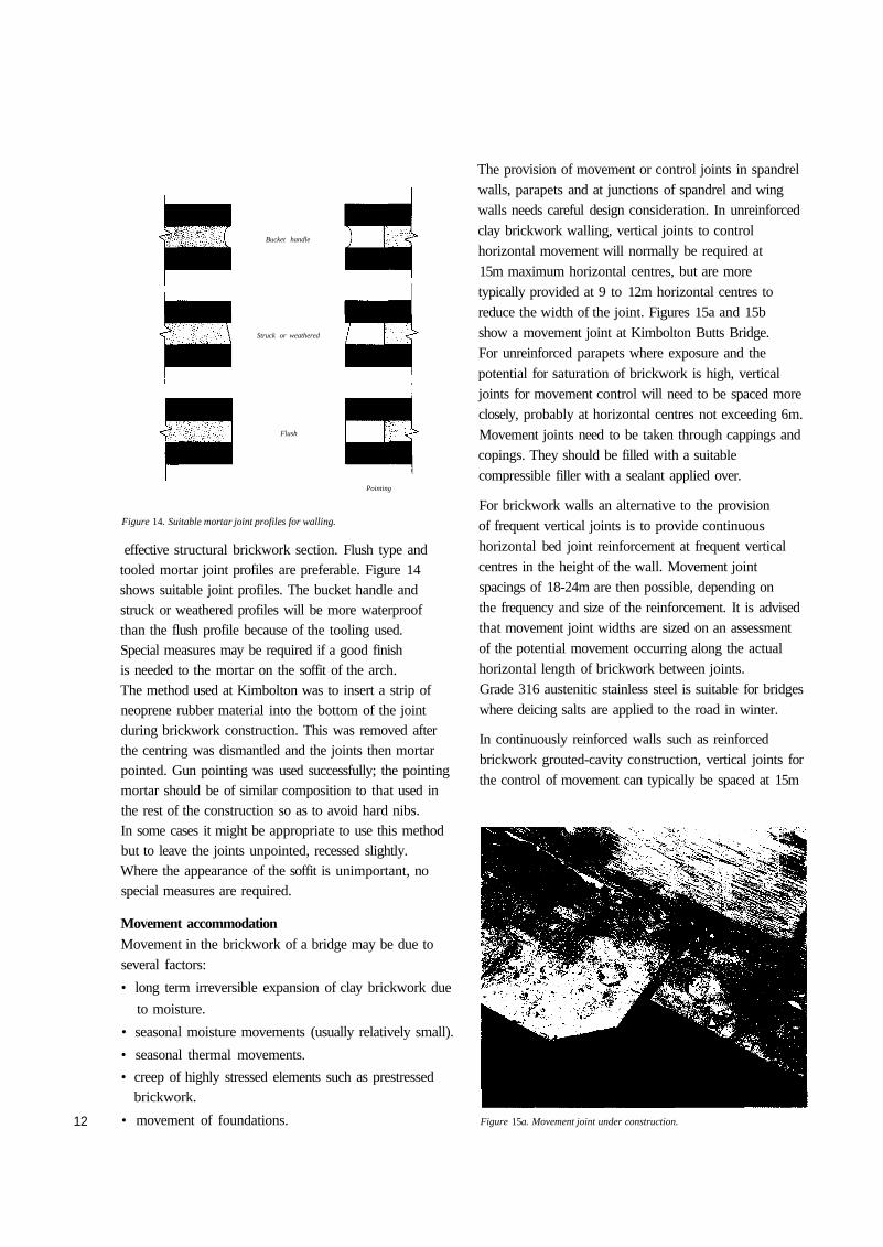
Struck or weathered
12
Figure 14. Suitable mortar joint profiles for walling.
effective structural brickwork section. Flush type andtooled mortar joint profiles are preferable. Figure 14shows suitable joint profiles. The bucket handle andstruck or weathered profiles will be more waterproofthan the flush profile because of the tooling used.Special measures may be required if a good finishis needed to the mortar on the soffit of the arch.The method used at Kimbolton was to insert a strip ofneoprene rubber material into the bottom of the jointduring brickwork construction. This was removed afterthe centring was dismantled and the joints then mortarpointed. Gun pointing was used successfully; the pointingmortar should be of similar composition to that used inthe rest of the construction so as to avoid hard nibs.In some cases it might be appropriate to use this methodbut to leave the joints unpointed, recessed slightly.Where the appearance of the soffit is unimportant, nospecial measures are required.
Movement accommodationMovement in the brickwork of a bridge may be due toseveral factors:
• long term irreversible expansion of clay brickwork due
to moisture.
• seasonal moisture movements (usually relatively small).
• seasonal thermal movements.
• creep of highly stressed elements such as prestressedbrickwork.
• movement of foundations.
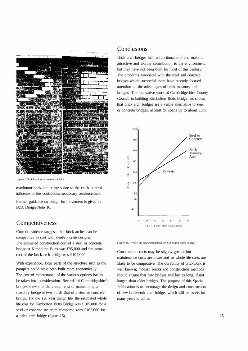
The provision of movement or control joints in spandrelwalls, parapets and at junctions of spandrel and wingwalls needs careful design consideration. In unreinforcedclay brickwork walling, vertical joints to controlhorizontal movement will normally be required at15m maximum horizontal centres, but are moretypically provided at 9 to 12m horizontal centres toreduce the width of the joint. Figures 15a and 15bshow a movement joint at Kimbolton Butts Bridge.For unreinforced parapets where exposure and thepotential for saturation of brickwork is high, verticaljoints for movement control will need to be spaced moreclosely, probably at horizontal centres not exceeding 6m.Movement joints need to be taken through cappings andcopings. They should be filled with a suitablecompressible filler with a sealant applied over.
For brickwork walls an alternative to the provisionof frequent vertical joints is to provide continuoushorizontal bed joint reinforcement at frequent verticalcentres in the height of the wall. Movement jointspacings of 18-24m are then possible, depending onthe frequency and size of the reinforcement. It is advisedthat movement joint widths are sized on an assessmentof the potential movement occurring along the actualhorizontal length of brickwork between joints.Grade 316 austenitic stainless steel is suitable for bridgeswhere deicing salts are applied to the road in winter.
In continuously reinforced walls such as reinforcedbrickwork grouted-cavity construction, vertical joints forthe control of movement can typically be spaced at 15m
Figure 15a. Movement joint under construction.
Flush
Bucket handle
Pointing
Conclusions
Figure 15b. Elevation on movement joint.
maximum horizontal centres due to the crack controlinfluence of the continuous secondary reinforcement.
Further guidance on design for movement is given inBDA Design Note 10.
CompetitivenessCurrent evidence suggests that brick arches can becompetitive in cost with steel/concrete designs.The estimated construction cost of a steel or concretebridge at Kimbolton Butts was £95,000 and the actualcost of the brick arch bridge was £104,000.
With experience, some parts of the structure such as the
parapets could have been built more economically.
The cost of maintenance of the various options has to
be taken into consideration. Records of Cambridgeshire's
bridges show that the annual cost of maintaining a
masonry bridge is two thirds that of a steel or concrete
bridge. For the 120 year design life, the estimated whole
life cost for Kimbolton Butts Bridge was £185,000 for a
steel or concrete structure compared with £163,000 for
a brick arch bridge (figure 16).
Brick arch bridges fulfil a functional role and make an
attractive and worthy contribution to the environment,
but they have not been built for most of this century.
The problems associated with the steel and concrete
bridges which succeeded them have recently focused
attention on the advantages of brick masonry arch
bridges. The innovative work of Cambridgeshire County
Council in building Kimbolton Butts Bridge has shown
that brick arch bridges are a viable alternative to steel
or concrete bridges, at least for spans up to about 15m.
Steel orConcrete
BrickMasonry-Arch
0 20 40 60 80 100 120
Time : Years after Construction
Figure 16. Whole life cost comparison for Kimbolton Butts Bridge.
Construction costs may be slightly greater but
maintenance costs are lower and so whole life costs are
likely to be competitive. The durability of brickwork is
well known; modern bricks and construction methods
should ensure that new bridges will last as long, if not
longer, than older bridges. The purpose of this Special
Publication is to encourage the design and construction
of new brickwork arch bridges which will be assets for
many years to come.
13
35 years
\Vho
le
1ife
C
ost
(£,00
0's)
200
180
160
l40
120
1O0
80
60
40
14
ReferencesBDA Publications• Building Note 1. Brickwork: good site practice.
Knight, TL. 1991.
• Design Note 7. Brickwork durability.Harding, J R and Smith, R A. 1986.
• Design Note 10. Designing for movement inbrickwork. Morton, J. 1988.
• Design Guide 2. The design of brickwork retainingwalls. Haseltine, B A and Tutt, J N. 1991.
• Engineers File Note 12. Post-tensioned brickworkabutments at Glinton Bypass. Halsall, R. 1991.
BSI Standards
• BS 3921:1985 (1995). Clay bricks.
• BS 4729:1990. Dimensions of bricks of specialshapes and sizes.
• BS 5400:Parts 1-10. Steel, concrete and compositebridges.
• BS 5628. Use of masonry. Part 1:1992: Structuraluse of unreinforced masonry.
• BS 5628. Use of masonry. Part 2:1995: Structuraluse of reinforced and prestressed masonry.
• BS 5628. Use of masonry. Part 3:1985: Materialsand components, design and workmanship.
• BS 5642:Part 2:1983. Copings of precast concrete,cast stone, clayware, slate and natural stone.
Department of Transport et al Design Manual for Roadsand Bridges
• BA 16. The assessment of highway bridges andstructures.
• BD 21. The assessment of highway bridges andstructures.
• BD 37. Loads for highway bridges.
• BD 41. Reinforced clay brickwork retaining walls ofpocket-type and grouted-cavity type construction.
• BD 52. The design of highway bridge parapets.
• BD 59. Design of highway bridges for hydraulicaction.
(The Design Standard, BD, and Advice Note, BA, on theconstruction of masonry arch bridges are in the course ofpreparation).
Other:
• The assessment and design of unreinforced masonryvehicle parapets. County Surveyors' Society. 1995.
• TRL State of the Art Review: Masonry arch bridges.Page, J. 1993. HMSO, London.
Photography:
Frank Walter, cover photographs
British Waterways, Figs 2a, 2b, 2c, 3
John Page, Fig 2d
BDA, Figs 1, 5, 7, 11, 12, 13, 15a, 15b
David Cox, Figs 8, 9
BDA would like to thank British Waterways Technical Services
for their assistance with photographs.
The contents of this publication are intended for guidance only
and any person intending to use these contents for the purpose
of design, construction or repair of brickwork or any related
project should first consult a Professional Advisor.
The Brick Development Association, its servants, and any
persons who contributed or to or who were in any way
connected with this publication accept no liability arising from
negligence or other reason howsoever caused for any injury or
damage to any person or property as a result of any use or
reliance on any method, product, instruction, idea, or other
contents of this publication.
April 1996 © Brick Development Association
Woodside House, Winkfield, Windsor, Berkshire SL4 2DX Tel: 01344 885651 Fax: 01344 890129


![Kulpa, Paula (MTC) [mailto:Paula.Kulpa@ontario.ca] Sent: … · 2020. 1. 24. · Subject: Bowstring Arch Bridges, Municipal Class EA Projects: Bowstring Arch Bridges, Humber Bridge](https://img.pdfslide.us/doc/110x75/5fc4a06febce581c3266c1e7/kulpa-paula-mtc-mailtopaulakulpa-sent-2020-1-24-subject-bowstring.jpg)