Embed Size (px)
Citation preview
TMS Journal September 2007 �
1 TMS Member, M. ASCE, PE Professor, Construction Management Technology Program, Department of Technology, University of Maryland Eastern Shore
Brick Veneer Steel Stud Wall Systems: State-of-the-Art
Joseph O. ArumalaMasonry cavity wall construction has come into its
own in the last 40 years. Prior to that time, masonry walls generally consisted of various types of solid masonry in multiple wythes [Wilkin (2003)]. The backup structure be-gan as concrete block masonry, but has evolved into steel stud wall construction with a type of wallboard sheath-ing. According to Rutila (1998). the first version of the brick veneer with steel stud wall system, shown in a 1�68 manufacturer’s catalog, was quite primitive by today’s standards of good practice. The recommended details did not show any weather barrier on top of the gypsum sheath-ing. The flashing did not extend through the wall but was stopped at the toe of the shelf angles and was tucked flat under the steel stud. There were no soft joints under the relieving angles and corrugated 24-gage brick ties were specified. The Standards slowly improved over the years, until in the early 1�80s they were in substantial agreement with present day practice [Newman (2001)]. This seems to suggest the general notion that the system was introduced to the construction industry without adequate research and with flawed design guides.
Since its introduction, the brick veneer with steel stud backup wall system has evolved into a successful construction method used in a wide variety of commercial, industrial and institutional structures which include such building types as schools, churches, hospitals and office buildings. These buildings usually have structural frames of steel or reinforced concrete. Unlike residential construc-tion, they generally are not designed with overhangs, eaves or gutters to protect the veneer and frequently incorporate parapets. They also are usually taller than residential struc-tures. Consequently, commercial brick veneer steel stud wall systems have greater exposure to their environment than their residential counterparts. For this reason, it is important to closely observe proper design, detailing and construction practices to ensure that expected and required levels of performance are met [BIA (1���)].
The brick veneer steel stud wall system is considered an anchored veneer wall. An anchored veneer is a brick wythe secured to and supported laterally by the back-ing through anchors (ties) and supported vertically by the foundation or other structural elements. The veneer transfers out-of-plane load directly to the backing and is
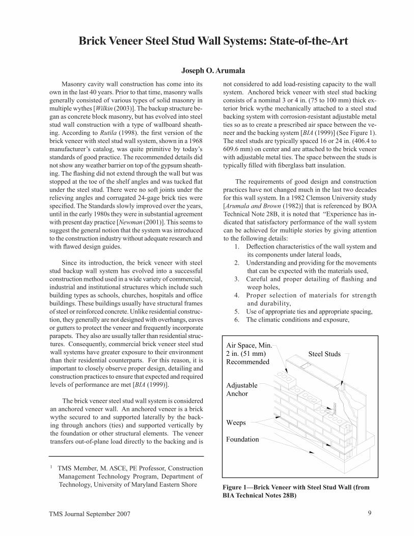
not considered to add load-resisting capacity to the wall system. Anchored brick veneer with steel stud backing consists of a nominal 3 or 4 in. (75 to 100 mm) thick ex-terior brick wythe mechanically attached to a steel stud backing system with corrosion-resistant adjustable metal ties so as to create a prescribed air space between the ve-neer and the backing system [BIA (1���)] (See Figure 1). The steel studs are typically spaced 16 or 24 in. (406.4 to 60�.6 mm) on center and are attached to the brick veneer with adjustable metal ties. The space between the studs is typically filled with fiberglass batt insulation.
The requirements of good design and construction practices have not changed much in the last two decades for this wall system. In a 1�82 Clemson University study [Arumala and Brown (1�82)] that is referenced by BOA Technical Note 28B, it is noted that “Experience has in-dicated that satisfactory performance of the wall system can be achieved for multiple stories by giving attention to the following details:
1. Deflection characteristics of the wall system and its components under lateral loads,
2. Understanding and providing for the movements that can be expected with the materials used,
3. Careful and proper detailing of flashing and weep holes,
4. Proper selection of materials for strength and durability,
5. Use of appropriate ties and appropriate spacing,6. The climatic conditions and exposure,
Figure 1—Brick Veneer with Steel Stud Wall (from BIA Technical Notes 28B)
Air Space, Min. 2 in. (51 mm) Recommended
Steel Studs
Adjustable Anchor
Weeps
Foundation
10 TMS Journal September 2007
7. Understanding the manner in which brick behaves,8. Good construction techniques.”
These recommendations are parallel to current require-ments for the wall system [BIA (1���), MSJC (2005)].
ADVANTAGES
The brick veneer steel stud wall system offers sev-eral advantages over other claddings. The system dem-onstrates superior performance in many specific areas of concern for designers, contractors and property owners such as attractive appearance, light weight, which al-lows for smaller supporting framing and foundations, ease of insulation, low thermal transmission rate, ease of construction, low maintenance, and cost efficiency [BIA (1���), Newman (2001)].
PROBLEMS WITH THE WALL SYSTEM: WAT E R P E N E T R AT I O N – WAT E R TIGHTNESS AND CORROSION
The brick veneer is expected to admit some water into the cavity but properly functioning waterproofing, flash-ing, and weep holes are designed to promptly direct the water out. However, this control of water in and through the wall has been the biggest challenge to designers and builders of the system. It has been reported that the brick veneer steel stud wall system is vulnerable to moisture damage [Cowie (1��0)]. In environmental studies done on the wall system, it was found that corrosion of the galvanized steel studs was detected a few days after the start of the tests and at a low rate of air leakage flow [Drysdale et al. (1�8�)]. Gumpertz and Bell (1�85) evaluated the wall system and reported the investiga-tion of problems with brick veneer steel stud walls on twelve buildings. All the reported corrosion problems on the wall system were traced to the effect of water and water vapor penetration of the wall system. In fact excessive moisture penetration into and accumulation in the cavity and the condensation of moisture in the wall have the potential of causing corrosion in:
• the brick-tie connections to the studs, • the studs themselves, • the threads of the fastener screws.
These issues have been addressed [Newman (2001), Cowie (1��0), Gumpertz and Bell (1�85), Drysdale et al. (1�8�)] and the MSJC and the BIA Technical Notes 28B give guide-lines for design and construction of the system including the selection of materials, ties, studs, vapor barriers and air retarders, proper installation of weep holes and flashings, insulation and placement of expansion joints to minimize this problem. The indication is that successful performance of the wall system is more likely if these recommendations are implemented.
Early in the use of the system as well as currently, there were also workmanship and specification problems that led to poor performance of the wall. Some of the common errors in workmanship or specifications are:
• mortar droppings left in the cavity, • no weep holes installed,• flashing not specified (a design issue), omitted by
the contractor, or improperly installed,• wall ties omitted or not properly anchored to
the studs,• use of steel studs with smaller thickness than the
minimum recommendation (minimum 20-gauge for exterior walls and minimum 18-gauge for buildings over three stories), and
• framing at openings not designed to accommo-date the strength lost by the studs cut to make the opening.
BRICK VENEER WITH STEEL STUD BACKUP WALL FAILURES
Information on the number and causes of brick veneer steel stud wall failures is not readily available. Owners, architects, and contractors are reluctant to be identified with problems systems. Though many lawsuits have involved brick veneer steel stud walls, most have been settled out of court, restricting the reporting on them. Nevertheless, insurance reports provide some clue. Architects who carry “errors and omissions” insurance are required to report on potential claims. Out of 250 open claims involving exterior wall problems that one such carrier in Canada has, more than 100 are related to brick veneer steel stud walls [Cowie (1��0)]. Some cases of failures recorded in the literature are given in this section.
Alderney Manor, Dartmouth, Nova Scotia
In 1�77, Alderney Manor, a 12-story apartment building in Dartmouth, Nova Scotia, suffered the first major brick veneer steel stud wall failure in Canada [Cowie (1�76)]. Within 3 years after the building was constructed, the steel studs and gypsum board sheathing that covered the steel studs were so dam-aged from rainwater that the brickwork and windows had to be completely removed and replaced. The failure of the building was identified as poor design and construction.
Federal Building, Norfolk, VA
In this case, the defects in a 1�-year-old 150,000-ft2
(13,�35 mm2) federal office building in Norfolk, Va., were so pervasive that the building had to be totally stripped of its exterior walls and reclad with precast concrete panels [ENR (1��7)], Newman (2001)].
TMS Journal September 2007 11
10-Year Old Building
The problems with this building show that corro-sion of steel studs can be devastating and can take place surprisingly fast. Gumpertz and Bell (1�85) report on this building that was less than 10 years old in which the painted (not galvanized) steel studs were found to be Completely corroded through in some places. However, steel studs and brick ties made of galvanized steel are not always the weakest link in this system. Instead the weakest link is typically the fasteners attaching the brick ties to the steel studs [Newman (2001)].
1972 4-Story Office Building
Biggs (2000) reports a case involving a four-story office building constructed in 1972 that developed veneer problems and required repairs in 2000. In 1��8, the owner became concerned over movement observed at the first-floor windows on the south elevation. Horizontal cracks and bulges had developed in the brick veneer at the sec-ond floor. In addition, vertical cracks had occurred at the corners, and several limestone pieces above the first-floor windows had shifted outward. In spite of the problems observed, the exterior veneer had performed well for nearly 30 years. However, the problems had reached a point that repairs were required for safety reasons. The cornerstones were in jeopardy of slipping off the relieving angle which then may have caused a collapse of large sections of the veneer.
This brick veneer over metal studs did not have any of the classical problems of anchor, tie, and fastener corrosion. Were it not for the problem with the relieving angles, the veneer would likely be performing well today. However, the details used on this project are not ones to be emulated. The sheathing should have been water-resistant and should have had a moisture barrier. The flashing should have extended to the outer face of the veneer. It is noted here that:
1. Not all brick veneers over metal studs suffer cor-rosion problems with the studs, anchors, and ties. Each building has to be evaluated independently.
2. While a building may have relieving angles, it should not be taken for granted that they were designed and built properly. The effectiveness of the relieving angles should be verified through analyses and probes.
Apartment Building, Halifax, Nova Scotia
In 1�88, after only 3 years of occupancy, an apartment building in Halifax, Nova Scotia exhibited deterioratation of the gypsum sheathing and corrosion of the self-tapping screws that anchored the gypsum to the steel studs [Cowie (1��0)].
6-Story Apartment Building, St. John’s, Newfoundland
In 1988, after just 1 year occupancy, a six-story apart-ment building in St. John’s, Newfoundland was deemed so severely damaged that the brick veneer had to be com-pletely removed and replaced. Instead of exterior grade gypsum sheathing and building paper, the cavity side of the steel studs had been covered with 1-inch thick glass fiber sheathing. The wire wall ties were connected to the steel studs by horizontal steel plates that projected through the joints of the glass fiber sheathing. Large amounts of water leaked into the backup wall and rusted the steel studs. The ties were a problem. Installed with eccentricities as great as 1 7/8 in. (47.6 mm), 3/16 in. (4.8 mm) diameter wire ties used in this apartment building were not strong enough to support the veneer [Cowie (1��0)].
Calvert Building
Constructed in Baltimore, Maryland in 1�81, the Calvert Building is a five-story, steel-framed building that serves as headquarters for the Maryland Casualty Insurance Company. The exterior walls consist of a brick veneer with a steel-stud backup wall, and horizontal strip windows. When the causes of facade water leakage and cracks in the brick veneer were investigated, it was discovered that water bypassed the concealed wall flashings above the strip windows allowing water to leak into the building. Additionally, the window sills were not adequately attached to the building. It was also determined that the cracks in the brick veneer resulted from ineffective expansion joints. The repair process was done with limestone because matching replacement brick for the Calvert Building was no longer available.
The Canada Mortgage and Housing Corporation Research
The subject of this research project was an exterior wall section on the top floor of a seven-story residential building in Ottawa built in 1��0. Instrumentation was incorporated in the wall to allow temperatures, air pressure and moisture to be monitored in key locations inside and outside the wall . The installation was monitored, with data read minute-by-minute and recorded as hourly averages, over several two-week periods, spread through all seasons of the year, starting in the winter of 1991 and extended to the summer of 1997. The key findings of the study is that the test wall did not perform in a satisfactory manner even though it was built in accordance with existing codes, standards, and construction practices. Thermal bridging at the studs and heat lost by air leakage compromised the thermal resistance of the assembly. Accumulations of moisture, mainly due to air leakage, were such that premature deterioration of the brick, ties, sheathing, and steel stud framing, is likely.
12 TMS Journal September 2007
Moisture in the brick was not uniformly distributed. At the interior face, during freezing conditions, moisture content was sufficient to eventually cause spalling into the cavity. These findings imply that improved design is required to ensure satisfactory long-term performance of brick veneer steel stud wall systems, good construction quality notwith-standing. Even with better-than-average workmanship, the following design improvements, relative to the test wall assembly, were recommended:
• insulation in the cavity, sufficient to keep the gypsum sheathing above the interior air dew point temperature (this will also reduce thermal bridging of framing),
• better airtightness, to reduce latent heat loss and reduce condensation in brickwork,
• a larger minimum cavity depth, to promote drain-age and drying, and
• better venting of the cavity (arranged to exclude rain) [CMHC (2000)].
STANDARDS/TECHNICAL NOTES
There are some useful sources of information on the proper design and construction details of this wall system. The MSJC (2005) and the BIA Technical Notes 28B [BIA (1���)] are discussed here.
The Masonry Standards Joint Committee (MSJC) has a chapter on Veneer that covers the design of anchored ve-neer including the veneer, backup system, anchors/ties and requirements in high wind regions and in areas of higher seismic risk. The general design requirements include:
• Design and detail the backing system of exte-rior veneer to resist water penetration. Exterior sheathing shall be covered with a water-resistant membrane unless the sheathing is water resistant and the joints are sealed.
• Design and detail flashing and weep holes in exte-rior veneer wall systems to resist water penetration into the building interior. Weep holes shall be at least 3/16 in. (4.8 mm) in diameter and spaced less than 33 in. (838 mm) on center.
The section on Brick Veneer with Steel Stud Backup has the following requirements:
• attach veneer with adjustable anchors,• attach each anchor to steel framing with corrosion-
resistant screws that have a minimum nominal shank diameter of 0.1�0 in. (4.8 mm),
• cold-formed steel framing shall be corrosion re-sistant and have a minimum base metal thickness of 0.043 in. (1.1 mm),
• maintain a 4½ in. (114 mm) maximum distance between the inside face of the veneer and steel framing. Maintain a 1 in. (25.4 mm) minimum air space.
Areas of High Winds: In areas of high speed, where the basic wind speed exceeds 110 mph (117 km/hr) but does not exceed 130 mph (209 km/hr) and the building’s mean roof height is less than or equal to 60 ft (18.3 m), the code recommends the following:
• Reduce the maximum wall area supported by each anchor to 70% of that required when the backup is wood.
• Space anchors at a maximum of 18 in. (457 mm) horizontally and vertically.
• Provide additional anchors around openings larger than 16 in. (406 mm) in either direction. Space an-chors around perimeter of opening at a maximum of 24 in. (610 mm) on center. Place anchors within 12 in. (305 mm) of openings.
The requirements of the system in Seismic Zones C, D and E provide for the isolation of the veneer from the supporting system and include the following:
Seismic Design Category C
• Isolate the sides and top of anchored veneer from the structure so that vertical and lateral seismic forces resisted by the structure are not imparted to the veneer.
Seismic Design Category D
• Isolate the sides and top of anchored veneer from the structure so that vertical and lateral seismic forces resisted by the structure are not imparted to the veneer.
• Reduce the maximum wall area supported by each anchor to 75 percent as follows: (1) For adjust-able two-piece anchors, anchors of wire size W1.7 (MW11), and 22 gage (0.8 mm) corrugated sheet-metal anchors provide at least one anchor for each 75% of 2.67 ft2 (0.3 m2) of wall area and (2) For other anchors, provide at least one anchor for each 75% of 3.5 ft2 (0.33 m2) of wall area. Maximum horizontal and vertical spacings are unchanged.
Seismic Design Category E and F
• Support the weight of anchored veneer for each story independent of other stories.
• Provide continuous, single wire joint reinforce-ment of minimum wire size W1.7 (MW 11) at a maximum spacing of 18 in. (457 mm) on center vertically. Mechanically attach anchors to the joint reinforcement with clips or hooks.
According to the MJSC [MSJC (2005)] Commentary,
“These requirements provide several cumulative effects to improve veneer performance under seismic load. Many
TMS Journal September 2007 13
of these provisions are based on similar requirements found in Chapter 30 of the Uniform Building Code [ICBO (1��7)]. The isolation from the structure reduces accidental loading and permits larger building deflections to occur without veneer damage. Support at each floor articulates the veneer and reduces the size of potentially damaged areas. An increased number of anchors increases veneer stability and reduces the possibility of falling debris. Joint reinforcement provides post cracking strength. Added ex-pansion joints further articulate the veneer, permit greater building deflection without veneer damage and limit stress development in the veneer.”
BIA’s Technical Notes 28B [BIA (1���)] is one of the most authoritative sources on the subject. This document contains structural design criteria, as well as recommenda-tions for avoiding water penetration, the minimum size of the air space, maximum tie spacing, and other important aspects of design. The Notes also address the considerations and recommendations for the design, detailing, materials selection and construction of brick veneer steel stud panel walls. The Notes is in several sections including:
• properties of Brick Veneer Steel Stud Walls which deals with materials, moisture resistance, thermal properties, fire resistance and acoustical properties,
• structural Design which deals with building codes, wall system behavior, ties, and seismic design,
• detailing which includes foundations, drainage cavity, flashing and weep holes, moisture barriers, lintels and shelf angles, vertical and horizontal joints, bond breaks, horizontal joint reinforcement, insulation, and condensation,
• selection of Materials which include bricks, steel, sheathing, screws, ties, moisture barrier, air barriers and vapor retarders and flashing,
• construction which includes workmanship and protection of brickwork in progress, and
• maintenance which includes direction on annual inspections.
LIQUID WATER AND WATER VAPOR CONTROL
Brick veneer construction incorporates a drainage cavity to deter water penetration into the building. This air space creates a physical separation between the brick wythe and the inner steel stud wall. When the wind-driven rain penetrates the veneer wythe, the cavity allows the water to drain down the back face of the brick. This water is then collected at the base of the wall by flashing and channeled out to the exterior through weep holes. When properly designed and constructed, a brick veneer steel stud system is resistant to water penetration through the entire assembly [BIA (1999)]. Measures to minimize water infiltration into the wall system are often introduced with various levels of success depending on the system design and installa-tion [Treshel (1��4), Treshel (2001), Gerns et al. (2003)].
Important factors in this control include: • The integrity of the mortar joints between brick
masonry units. • Properly designed, detailed, and installed flashings. A
properly designed flashing system can both directly protect steel support elements as well as enable water in the cavity to flow out of the wall to the exterior. Stainless steel, copper, and lead coated copper are effective and durable flashing materials.
• The phenomenon of thermal bridging, where heat bypasses the cavity insulation and is transferred through the steel studs. Testing has shown that, depending on the specific design, thermal bridging can reduce the effectiveness of cavity insulation considerably. This insulation problem can lead to moisture problems.
• Careful and proper design, detailing, and placement of weep holes.
• Moisture Intrusion. Moisture that enters the wall cavity can condense if it reaches a cold spot (dew point). A steel stud may provide that cold spot if the wall is not insulated properly. Condensation in walls can lead to corrosion of the steel studs, loss of R-value and moisture movement.
• Relative humidity and temperature differentials across a building envelope. These differencials cause moisture migration through building ma-terials as a function of their resistance to thermal and vapor permeability. Air infiltration provides direct transfer of humid air to wall cavities and can greatly exacerbate condensation. The col-lection of condensed water vapor on interior building materials can cause architectural and/or structural damage. Corrosion of steel, wood rot, and mold growth are common. Air and vapor retarders should be designed and installed on the exterior side of the stud framing to reduce moisture and moisture vapor and to prevent convection pressure differentials. Continuous moisture barriers should be installed between the exterior sheathing and the building facade [O’Saben et al. (2003)].
• Insulations, as they can help prevent condensation by reducing air infiltration, limiting the amount of moisture penetration and keeping the cavity tem-perature above the dew-point temperature.
• Mechanisms to prevent rainwater from crossing the cavity between the veneer and the backup wall. For instance, the cavity must be kept free of mortar droppings during construction. Mortar droppings can clog weep holes and create bridges that let water cross the cavity. A clean air cavity free of mortar droppings is so important that BIA now says the cavity should not be less than 2 inches for commercial buildings. This minimum air cavity requirement is to reduce the potential for mortar bridging of the cavity.
14 TMS Journal September 2007
SUGGESTED SOLUTIONS
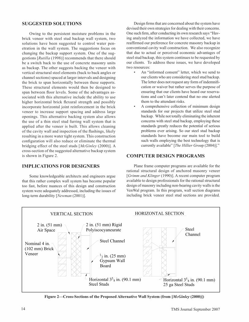
Owing to the persistent moisture problems in the brick veneer with steel stud backup wall system, two solutions have been suggested to control water pen-etration in the wall system. The suggestions focus on changing the backup support system. One of the sug-gestions [Rutilla (1��8)] recommends that there should be a switch back to the use of concrete masonry units as backup. The other suggests backing the veneer with vertical structural steel elements (back to back angles or channel sections) spaced at larger intervals and designing the brick to span horizontally between these supports. These structural elements would then be designed to span between floor levels. Some of the advantages as-sociated with this alternative include the ability to use higher horizontal brick flexural strength and possibly incorporate horizontal joint reinforcement in the brick veneer to increase support spacing and address large openings. This alternative backing system also allows the use of a thin steel stud furring wall system that is applied after the veneer is built. This allows cleaning of the cavity wall and inspection of the flashings, likely resulting in a more water tight system. This construction configuration will also reduce or eliminate the thermal bridging effect of the steel studs [McGinley (2000)]. A cross-section of the suggested alternative backup system is shown in Figure 2.
IMPLICATIONS FOR DESIGNERS
Some knowledgeable architects and engineers argue that this rather complex wall system has become popular too fast, before nuances of this design and construction system were adequately addressed, including the issues of long-term durability [Newman (2001)].
HORIZONTAL SECTIONVERTICAL SECTION
2 in. (51 mm) Air Space
2 in. (51 mm) Rigid Polyiscocyaneurate
Steel Channel
12 in. (25 mm)
Gypsum Wall Board
Horizontal 358 in. (�0.1 mm)
Steel Studs
Nominal 4 in. (102 mm) Brick Veneer
Steel Channel
Horizontal 358 in. (�0.1 mm)
25 ga Steel Studs
Figure 2—Cross-Sections of the Proposed Alternative Wall System (from [McGinley (2000)])
Design firms that are concerned about the system have devised their own strategies for dealing with their concerns. One such firm, after conducting its own research says “Hav-ing analyzed the information we have collected, we have reaffirmed our preference for concrete masonry backup in conventional cavity wall construction. We also recognize that due to actual or perceived economic advantages of steel stud backup, this system continues to be requested by our clients. To address these issues, we have developed two resources:
• An “informed consent” letter, which we send to our clients who are considering steel stud backup. The letter does not request any form of indemnifi-cation or waiver but rather serves the purpose of ensuring that our clients have heard our reserva-tions and can’t later contend that no one alerted them to the attendant risks.
• A comprehensive collection of minimum design standards for our projects that utilize steel stud backup. While not totally eliminating the inherent concerns with steel stud backup, employing these standards greatly reduces the potential of serious problems ever arising. So our steel stud backup standards have become our main tool to build such walls employing the best technology that is currently available” [The Hillier Group (2004)].”
COMPUTER DESIGN PROGRAMS
Plane frame computer programs are available for the rational structural design of anchored masonry veneer [Grimm and Klinger (1��0)]. A recent computer program available to design professionals for the rational structural design of masonry including non-bearing cavity walls is the VenWal program. In this program, wall section diagrams including brick veneer steel stud sections are provided.
TMS Journal September 2007 15
Types of required input data and an array of output data are listed. The VenWal program is able to predict lateral displacement, shear, bending moment on the masonry wall and axial forces on each tie/anchor under the design wind load [Grimm and Wang (2003)]. The program does not directly deal with effects of cracking of the brick veneer.
IMPORTANT DESIGN CONSIDERATIONS
Manufacturers of steel studs and sheathing materials have published literature on the design of steel stud back-ing for anchored masonry veneer [Brown and Arumala (1�82), BIA (1���)]. The post-cracking performance of the wall system is satisfactory if the wall is properly designed, constructed and maintained with appropriate materials [Kelly et al. (1��0)]. According to the BIA’s Technical Notes on Brick Construction, the key to a good cavity wall design, detailing and construction is to recognize that brick masonry is neither water resistant nor dimensionally stable. Even new, freshly laid brick masonry is porous to water. Brick masonry moves with moisture changes, tem-perature cycling and chemical attack, in addition to wind and seismic forces [BIA (1��8)]. The Masonry Standards Joint Committee [MSJC (2005)] states that when utilizing anchored masonry veneer, the designer should consider the following conditions and assumptions:
• The veneer may crack under service load.• Deflection of the backing should be limited to control
crack width in the veneer and to provide stability.• Connections of the anchor to the veneer and to the
backing should be sufficient to transfer applied loads.• Differential movement should be considered in
the design, detailing and construction.• Water will penetrate the veneer and the wall system
should be designed, detailed and constructed to prevent water penetration into the building.
• Requirements for corrosion protection and fire resistance must be included.
Important things to consider when designing a brick veneer with a steel stud backup wall system include: Not parallel construction again.
• Water penetration. • Masonry movement. • The need to restrict the flow of moisture laden air
and water vapor through the wall system. • The proper design and construction of continuous
through-wall flashings at masonry supports and around wall openings are critical to controlling water leakage through the masonry, and direct it to drain from the wall cavity through carefully and properly designed, detailed, and placed weep holes.
• The proper design and construction of a continu-ous air/vapor barrier needed to reduce the flow of moisture through the wall system to levels that can be handled by the wall materials without condensing in the walls or producing corrosion,
mold, ice or other conditions that contribute to the deterioration of the wall.
• The proper placement and sizing of expansion joints. • Properly sizing and placing wall ties, and
support angles or shelves stiff enough to limit masonry movements.
• Designing and detailing the veneer to accommo-date differential movement.
• The proper and well developed detailing for the cavity in the wall system.
• Decisions regarding flashing and weep holes, as a portion of the system for collecting and diverting moisture, as an integral part of the details. The type of flashing and placement of weep holes should therefore be carefully planned.
• Prevention of mortar droppings and other obstruc-tions from bridging the air space that separates the brick veneer and steel studs. Masons must make deliberate efforts to eliminate mortar droppings as much as possible by assuring that mortar spread as a bed joint is beveled or sloped away from the cavity. In addition, manufactured drainage fabrics are available for insertion into the cavity.
• Good workmanship must be ensured.• Keeping an open drainage path to weep holes by
including cavity inserts.
DIFFERENTIAL MOVEMENTS
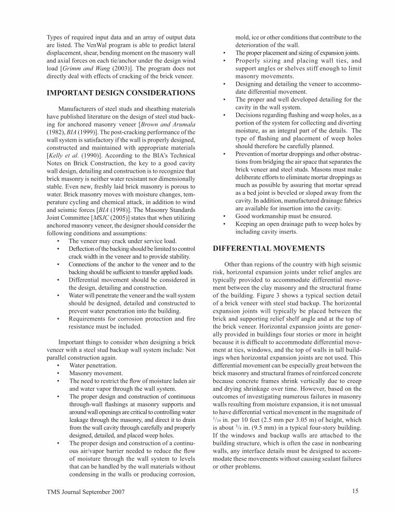
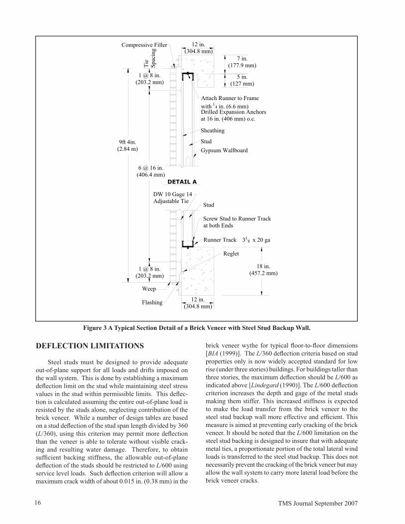
Other than regions of the country with high seismic risk, horizontal expansion joints under relief angles are typically provided to accommodate differential move-ment between the clay masonry and the structural frame of the building. Figure 3 shows a typical section detail of a brick veneer with steel stud backup. The horizontal expansion joints will typically be placed between the brick and supporting relief shelf angle and at the top of the brick veneer. Horizontal expansion joints are gener-ally provided in buildings four stories or more in height because it is difficult to accommodate differential move-ment at ties, windows, and the top of walls in tall build-ings when horizontal expansion joints are not used. This differential movement can be especially great between the brick masonry and structural frames of reinforced concrete because concrete frames shrink vertically due to creep and drying shrinkage over time. However, based on the outcomes of investigating numerous failures in masonry walls resulting from moisture expansion, it is not unusual to have differential vertical movement in the magnitude of 1/10 in. per 10 feet (2.5 mm per 3.05 m) of height, which is about 3/8 in. (�.5 mm) in a typical four-story building. If the windows and backup walls are attached to the building structure, which is often the case in nonbearing walls, any interface details must be designed to accom-modate these movements without causing sealant failures or other problems.
16 TMS Journal September 2007
6 @ 16 in. (406.4 mm)
�ft 4in.(2.84 m)
Stud
Screw Stud to Runner Track at both Ends
Runner Track 358 x 20 ga
DW 10 Gage 14 Adjustable Tie
18 in. (457.2 mm)
Flashing
Reglet
12 in. (304.8 mm)
DETAIL A
Compressive Filler
Tie
Spac
ing
7 in. (177.� mm)
5 in. (127 mm)
StudGypsum Wallboard
Attach Runner to Frame with 14 in. (6.6 mm) Drilled Expansion Anchors at 16 in. (406 mm) o.c.
12 in. (304.8 mm)
1 @ 8 in. (203.2 mm)
Sheathing
1 @ 8 in. (203.2 mm)
Weep
Figure 3 A Typical Section Detail of a Brick Veneer with Steel Stud Backup Wall.
DEFLECTION LIMITATIONS
Steel studs must be designed to provide adequate out-of-plane support for all loads and drifts imposed on the wall system. This is done by establishing a maximum deflection limit on the stud while maintaining steel stress values in the stud within permissible limits. This deflec-tion is calculated assuming the entire out-of-plane load is resisted by the studs alone, neglecting contribution of the brick veneer. While a number of design tables are based on a stud deflection of the stud span length divided by 360 (L/360), using this criterion may permit more deflection than the veneer is able to tolerate without visible crack-ing and resulting water damage. Therefore, to obtain sufficient backing stiffness, the allowable out-of-plane deflection of the studs should be restricted to L/600 using service level loads. Such deflection criterion will allow a maximum crack width of about 0.015 in. (0.38 mm) in the
brick veneer wythe for typical floor-to-floor dimensions [BIA (1���)]. The L/360 deflection criteria based on stud properties only is now widely accepted standard for low rise (under three stories) buildings. For buildings taller than three stories, the maximum deflection should be L/600 as indicated above [Lindegard (1��0)]. The L/600 deflection criterion increases the depth and gage of the metal studs making them stiffer. This increased stiffness is expected to make the load transfer from the brick veneer to the steel stud backup wall more effective and efficient. This measure is aimed at preventing early cracking of the brick veneer. It should be noted that the L/600 limitation on the steel stud backing is designed to insure that with adequate metal ties, a proportionate portion of the total lateral wind loads is transferred to the steel stud backup. This does not necessarily prevent the cracking of the brick veneer but may allow the wall system to carry more lateral load before the brick veneer cracks.
TMS Journal September 2007 17
WATERPROOFING THE BUILDING ENVELOPE
The National Concrete Masonry Association [NCMA (1��5)] states “Building weather tight walls with any mate-rial requires three essential things: proper design, quality materials and good workmanship”. Adequately controlling rainwater and moisture due to condensation in a brick veneer steel stud system will prevent damage and avoid unnecessary repairs to the brick veneer. In fact, water is the most destructive weathering element of materials used in building structures, including brick masonry [Kubal (1993)]. Waterproofing techniques preserve structural in-tegrity and usefulness through an understanding of natural forces and their effect during life cycling. Waterproofing also involves choosing proper designs and materials to counter the detrimental effects of these natural forces. To prevent all possible water intrusion causes, a building must be enveloped from top to bottom with waterproofing materials. These waterproof systems must then interact integrally to prevent water infiltration. Should any one of these systems fail or not act integrally with all other envelope systems, leakage will occur [Kubal (1��3)]. For the brick veneer steel stud wall system, this may mean revisiting the detailing and placement of vapor barriers and air retarders, improved design and special efforts made to keep the wall components dry and the cavity clean. Protecting the interior of a structure begins with sealing the building envelope to prevent water penetration. This can be accomplished by focusing on the building’s trouble spots: flashings, joints and coatings [Keeton (2004)]. It is possible to improve the water resistance of the brick veneer by applying some surface treatment including clear waterproofing coatings [Coney et al. (1�88)]. However, this practice has not been fully accepted in the industry because of the perception that applying the treatment will alter the inherent nature of bricks.
S C H E D U L E D M A I N T E N A N C E I S IMPORTANT
The first step to achieving timely and appropriate main-tenance is to make sure inspections are conducted regularly and properly. Moisture can be controlled through preventive measures during the design and construction stages of a project, along with a well-planned and scheduled mainte-nance program after completion [Keeton (2004)]. Brick veneer installations should be protected with functional drainage systems, field inspections and quality control.
A New Way to See Moisture in Walls
Efforts are underway to develop a way to use ultra wide-band radio waves to nondestructively detect moisture within the walls of a building [Engineering Times (2004)]. Laboratory experiments conducted on a simplified wall
section made of gypsum board, fiberglass insulation, and oriented strand board (OSB), demonstrated that the new method can locate moisture pockets to within one centi-meter (0.3� in. (�.� mm)). The technique involves sending a broad range of radio frequencies through typical drywall construction to look for a moisture signature in the signal that is reflected back. The presence of water within the model wall produced a stronger reflection of radio waves at specific frequencies. The elapsed time between transmis-sion of the waves and their arrival at a receiving antenna helps determine the location of the water. By processing the reflected signals with computer software, the researchers can create detailed three-dimensional maps that highlight wet areas. Research is continuing, in order to see how the apparatus performs with real walls that include studs, wires, pipes, and windows, which could complicate the readings [Engineering Times (2004)]. This application may be useful for planned maintenance and monitoring the movement of moisture in the wall system.
THE STATE-OF-THE-ART OF THE WALL SYSTEM
The brick veneer steel stud wall system has been sub-jected to serious criticisms due to some of the problems that have been experienced in these walls. While some critics would like the system withdrawn or discontinued from the construction industry, available data suggest that the wall can be viable if good design and construction practices are followed [Kelly et al. (1��0), BIA (1���), MSJC (2005)]. The main problems associated with the system are water leakage and the related deterioration and corrosion. This deteriora-tion is mainly related to water and water vapor penetration of the wall that causes corrosion of the metallic components and deterioration of the sheathings and insulation. Most of the problems reported with this wall system have occurred on walls where recommended design and construction practices have not been followed. However with the ex-perience gained, a well designed, detailed and constructed brick veneer steel stud wall system can be viable [Kelly et al. (1��0), BIA (1���), MSJC (2005)]. Careful attention has to be paid to material selection, the details of flashings and weep holes and control joints. It is important therefore that designers obtain a comprehensive collection of minimum design standards for the design of the system. Employing these standards will greatly reduce the potential of serious problems arising. These standards should be the main tools to design and build the walls employing the best technology that is currently available. For durability purposes, improved design of the wall system is required. This will involve look-ing into ways of keeping the wall system dry.
Construction Inspection and Meetings
For quality assurance purposes, it may be prudent to require “special inspection” of the installation of the wall
18 TMS Journal September 2007
components to insure that the wall system is constructed according to specifications. Inspection should focus on construction practices that, if not done properly, could lead to problems with water penetration including the installa-tion of flashings, weep holes, and control joints. Pre-bid and pre-construction meetings along with sample panels also assist in improving the quality and performance of the wall system.
CONCLUSION
The brick veneer with steel stud backup wall system has been used successfully in a wide variety of commercial, industrial, and institutional structures. However, it is recog-nized that the wall system is vulnerable if liquid water and water vapor condensation are not sufficiently controlled. Most of the reported cases of failures were due to poor material selection, design and construction practices. It is important to pay attention to design, detailing and construc-tion specifications and guidelines in order to minimize the water/moisture problems with the system. To assure safe and sound performance, brick veneer with steel stud backup walls must be properly designed, meticulously detailed and skillfully built under special inspection to control the flow of moisture in and out of the wall cavity and to keep the wall components dry. It is necessary to design and construct the wall envelope to be watertight. However, there is need for design improvements to insure that the wall is kept dry in service. This may mean that the air cavity thickness may be increased to promote drainage and drying. Maintenance is also critically important to ensure the system remains functioning as needed.
RECOMMENDATIONS
For long term performance of the wall system the fol-lowing issues must be addressed:
1. Improved design and construction details for the wall system with a view to improving its perfor-mance against water penetration.
2. Increasing the width of the air space in the wall to reduce the potential of mortar bridging of the cavity, to improve the control of water in the cav-ity and keeping it dry.
3. Incorporation of provisions for “Special Inspec-tion” in the construction of the wall.
4. Carry out regular inspections of the wall system and have a well planned scheduled maintenance program.
REFERENCES
Arumala, J. O. and Brown, R. H., “Performance Evaluation of Brick Veneer with Steel Stud Backup”, Department of Civil Engineering, Clemson University, Clemson, South Carolina, April 1�82.
BIA 1��8, “Brick Masonry Cavity Walls: Introduction,” Technical Notes on Brick Construction No. 21, Rev., Brick Industry association, Reston, VA., 1998.
BIA 1999, “Brick Veneer/Stud Panel Walls,” Technical Notes on Brick Construction No. 28B, Rev. II, Brick In-dustry association, Reston, VA., 1999.
Biggs, D. T., “Repairing Masonry Cracks,” Structure, pp. 25-31, Spring 2000.
Brown, R. H. and Arumala, J. O., “Brick Veneer with Metal Stud Backup – An Experimental and Analytical Study”, Proceedings Second North American Masonry Conference, The Masonry Society, Boulder, CO, pp. 12-1, to 13.20, August 1�82.
CMHC 2000, “Performance of A Brick Veneer/Steel Stud Wall System” Technical Series 00-138, Canada Mortgage and Housing Corporation, 2000.
Coney, W.B., J.G. Stockbridge, “The Effectiveness of Waterproofing Coatings, Surface Grouting, and Tuck-pointing on a Specific Project,” ASTM STP 992, Masonry Materials: Design, Construction, and Maintenance, pp. 220 – 224, 1�88.
Cowie, J. W. “Investigation of Exterior Walls, Windows and Roof, Alderney Manor, Alderney Dr., Darthmouth, Nova Scotia”, J. W. Cowie Engineering Limited, 583 Hollis St., Hallifax, Nova Scotia, Canada B3J 1V4, July 1976.
Cowie, J. W., “The Failure of Steel Studs” Publication #M�00082, The Aberdeen Group, 1��0.
Drysdale, R.G. and Kluge, A., “A Summary of Performance of Brick Veneer/Steel Stud Wall Systems Subject to Tem-perature, Air Pressure and Vapor Pressure Differential,” Seminar on Brick Veneer Wall Systems, Toronto, Ontario, Canada, June 1�8�.
Engineering Times, National Society of Professional En-gineers, Volume 26, Number 2, February 2004.
ENR 1997, “No Longer Red in the Face” ENR, , p. 33, May 26, 1��7.
Gerns, E. A. and Chan, L. M., “Corrosion, The Use of Metal Within Wall Systems and Associated Life-Cycle Issues”, Ninth North American Masonry Conference, Clemson, South Carolina, June 1-4, 2003.
Grimm, C. T. and Klinger, R.E., “ Crack Probability in Brick Veneer over Steel Studs” Proceedings Fifth North American Masonry Conference, The Masonry Society, Boulder, CO, pp 1323-1334, June 1��0.
TMS Journal September 2007 1�
Grimm, C. T., and Wang, S. T., “A Computer Program for Structural Design of Masonry Walls and Cavity Walls”, Ninth North American Masonry Conference, Clemson, South Carolina, June 1-4, 2003.
Gumpertz, W. H., and Bell, G. R., “Engineering Evaluation of Brick Veneer/Steel Stud Walls, Part 1 – Flashing and Waterproofing and Part 2 – Structural Design, Structural Behavior and Durability,” Proceedings, Third North Ameri-can Masonry Conference, Arlington, Texas, June 1985.
ICBO 1��7, Uniform Building Code, International Confer-ence of Building Officials, Whittier, CA, 1997.
Kelly T., Goodson, M., Mayes, R. and Asher, J., “Analy-sis of the Behavior of Anchored Brick Veneer on Metal Stud Systems Subjected to Wind and Earthquake Forces”, Proceedings Fifth North American Masonry Conference, The Masonry Society, Boulder, CO, pp. 135�-1370, June 1��0.
Keeton, B., “Prevent Water Intrusion and Minimize Expo-sure to Claims by Building with Mold in Mind” Construc-tion Executive, vol. 13, No. 7, pg 46-48, Association of Builders and Contractors, 4250 North Fairfax Drive, 9th Floor, Arlington, Virginia 22203, June 2004.
Kubal, M. T., “Water Proofing the Building Envelope”, McGraw Hill, 1��3.
Lindegard, R. J., “The Success of Steel Studs”, Publication #M�00087, The Aberdeen Group, 1��0.
McGinley, Mark W., “An Alternative Design for Brick Veneer Steel Stud Walls”, The Masonry Society Journal, The Masonry Society, Vol. 18, Number 2 pp. 9-22, De-cember 2000.
Masonry Standards Joint Committee (MSJC), “Building Code Requirements for Masonry Structures”, (ACI 530-05/ASCE 5-05/TMS 402-05), American Concrete Institute; Structural Engineering Institute of the American Society of Civil Engineers; The Masonry Society, Boulder CO, 2005.
NCMA-TEK 1�85, “Building Weathertight Concrete Masonry Walls,” NCMA-TEK 85, National Concrete Masonry Association, 2302 Horse Pen Rd., Herndon, VA 22070, 1�85,
Newman, A., “Structural Renovation of Buildings: Meth-ods, Details and Design Examples,” The McGraw-Hill Companies, pp. 800-807, 2001.
O’Saben, A. M. and Whitlock, A. R., “Moisture Vapor Prob-lems with Masonry Facades Over Steel Framing in Hot and Humid Climates,” North American Masonry Conference, Clemson, South Carolina, June 1-4, 2003.
Rutila, D. A., “Innovations in Brick Veneer,” The Construc-tion Specifier, October 1��8.
The Hillier Group,Designing Solutions, http://www.hillier.com – Private Communications, 2004.
Treshsel, H. R., editor, “Moisture Control in Buildings”, ASTM manual series MNL 18, 1994 American Society for Testing and Materials (ASTM), pp. 224-225, 1��4.
Treshsel, H. R., editor, “Moisture Analysis and Condensa-tion Control in Building Envelopes”, ASTM stock number MNL 40, 1994 American Society for Testing and Materials (ASTM) , pp. 67-68, 2001.
Wilkin, R. G., “Cavity Wall Construction”, STURCTURE Magazine, A Joint Publication of NCSEA/CASE/SEI, September 2003.

20 TMS Journal September 2007