Embed Size (px)
Citation preview
Arizona Geological Surveywww.azgs.az.gov | repository.azgs.az.gov
OPEN-FILE REPORT OFR-13-05
An EvAluAtion of CArbon DioxiDE SEquEStrAtion PotEntiAl in thE lukE
bASin, South-CEntrAl ArizonA
Brian F. GooteeArizona Geological Survey
July 2013
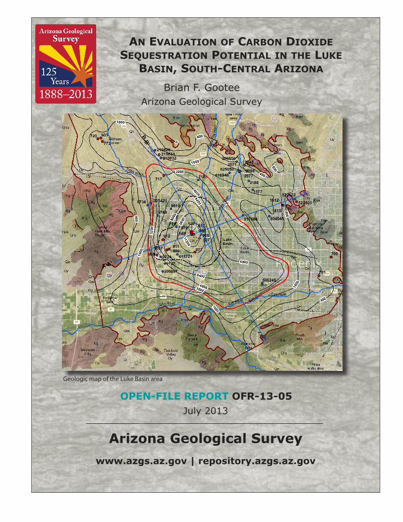
Geologic map of the Luke Basin area

Arizona Geological Survey
M. Lee Allison, State Geologist and Director
Manuscript approved for publication in July 2013Printed by the Arizona Geological Survey
All rights reserved
For an electronic copy of this publication: www.repository.azgs.az.govPrinted copies are on sale at the Arizona Experience Store
416 W. Congress, Tucson, AZ 85701 (520.770.3500)
For information on the mission, objectives or geologic products of the Arizona Geological Survey visit www.azgs.az.gov.
This publication was prepared by an agency of the State of Arizona. The State of Arizona, or any agency thereof, or any of their employees, makes no warranty, expressed or implied, or assumes any legal liability or responsibility for the accuracy, completeness, or usefulness of any information, apparatus, product, or process disclosed in this report. Any use of trade,
product, or firm names in this publication is for descriptive purposes only and does not imply endorsement by the State of Arizona.
___________________________
Recommended Citation: Gootee, B.F., 2013, An Evaluation of Carbon Dioxide Sequestration Potential in the Luke Basin, South-Central Arizona. Arizona Geological Survey Open File Report, OFR-13-05, 10 p., 2 map plates and 2 appendices.

An Evaluation of Carbon Dioxide Sequestration Potential in the Luke Basin, south-central Arizona
by
Brian F. Gootee
Research Geologist | Arizona Geological Survey
Arizona Geological Survey Open-File Report 13-05
July, 2013
Arizona Geological Survey
416 W. Congress St., #100
Tucson, Arizona 85701

Arizona Geological Survey
Table of Contents
1.0 Introduction .................................................................................................................... 1
2.0 Methods ......................................................................................................................... 1
3.0 Geologic setting .............................................................................................................. 2
4.0 Stratigraphy .................................................................................................................... 3
4.1 Valley-fill .......................................................................................................................... 3
4.2 Upper basin-fill ................................................................................................................. 3
4.3 Lower basin-fill ................................................................................................................. 4
5.0 Structure ......................................................................................................................... 5
6.0 Sealing Conditions .......................................................................................................... 6
7.0 Salinity ............................................................................................................................ 6
8.0 Conclusions ..................................................................................................................... 6
9.0 Acknowledgments & Disclaimer ..................................................................................... 6
10.0 References Cited ............................................................................................................. 8
Plates
1 Location map of the Luke basin
2 Geologic cross-sections AA’ and BB’
Appendices
A Well Inventory
B Borehole Log Data

Arizona Geological Survey
Geologic Evaluation of the Luke Basin for CO2 Sequestration Potential Page 1 of 10
1.0 Introduction
The Department of Energy (DOE), including its National Energy Technology Laboratory has established national programs to evaluate the technical feasibility of long-term subsurface geologic storage of carbon dioxide (CO2) produced by industrial activity. West Coast Regional Carbon Sequestration Partnership (WESTCARB) is a consortium of seven western U.S. States and one Canadian Province that is one of seven regional North American partnerships established to evaluate technical aspects of high-volume CO2 capture and sequestration. Collaborative WESTCARB research programs have included more than 90 public agencies, private companies, and non-profit organizations. The Arizona Geological Survey (AZGS) began work in 2010 on WESTCARB Phase III – Arizona Geological Characterization (California Energy Commission Agreement Number 500-10-024).
As part of WESTCARB Phase III, AZGS is evaluating the potential for CO2 sequestration in geologic formations that are below a level of 800 meters (m) (2,625 feet (feet)) depth below land surface (bls). This evaluation is directed at porous and permeable geologic formations with impermeable sealing strata in Cenozoic sedimentary basins in the Basin and Range Province, and Paleozoic sedimentary formations in the Colorado Plateau. An initial screening of Cenozoic sedimentary basins with significant depth and volume below the 800 m bls level resulted in ten candidate basins from a total of 88 basins (Spencer, 2011). This report represents ongoing WESTCARB assessment of CO2 storage potential in the Luke basin, one of ten Cenozoic basins in Arizona identified during the preliminary evaluation, and is part of Tasks 2 and 3 of Arizona WESTCARB Phase III. Task 2 consists primarily of characterizing basin structure, stratigraphy, lithology, and the nature of seals or a cap rock. This task also includes determining the storage capacity of permeable sediments below 800 depth (Spencer, 2011). Task 3 is to determine if, and at what depth, saline groundwater approaches 10,000 milligrams per liter (mg/L) of total dissolved solids (TDS), characterized in a separate study (Gootee and others, 2012). This concentration represents the threshold above which water is considered non-potable and unsuitable as drinking water (United States Environmental Protection Agency). Individual-basin studies such as this study are intended to provide estimates of the volume of permeable strata that are capped by impermeable strata (with an interface at depths greater than 800 m), and that are saturated with saline groundwater (>10,000 mg/L TDS).
Luke basin is a broad, northwest-trending Cenozoic basin in the south-central portion of the Basin and Range tectonic province. The White Tank, Estrella, and South Mountains border the west, south and southeast portions of the basin, respectively (Plate 1). The Hieroglyphic Mountains, Union Hills and Phoenix Mountains form the north and northeast boundary of the basin. Luke basin is drained by the Gila River on its southern margin, and includes segments of its major tributaries, the Salt, Agua Fria and New Rivers. Most of the Phoenix metropolitan area occupies the basin area, including major interstates I-10, I-17 and U.S. 60. Luke basin (Scarborough and Peirce, 1978) is also referred to as the West Salt River Valley subbasin, one of seven groundwater subbasins in the Phoenix Active Management Area (Reeter and Remick, 1986). Luke basin is estimated to be at least 3,600 m (12,000 feet) deep, with an estimated total sediment volume of 1,626 km3 (390 cubic miles (mi3)) (Spencer, 2011). Approximately 605 km3 (145 mi3) of basin-fill sediment is estimated to lie below a depth of 800 m (2,625 feet). Basin-fill sediments below a depth of 800 m occupy an area of approximately 680 km2 (263 mi2).
2.0 Methods
The DOE National Energy Technology Laboratory and Regional Carbon Sequestration Partnerships have developed methodologies for characterizing CO2 sequestration potential in sedimentary basins (DOE, 2010). In this report we analyze and interpret collected data that meet basic

Arizona Geological Survey
Geologic Evaluation of the Luke Basin for CO2 Sequestration Potential Page 2 of 10
criteria for characterizing the potential for carbon dioxide sequestration in the Luke basin. Although basalt is being considered for future opportunities in carbon capture and storage, and is present at depth in the Luke basin, basalt is not the focus of this characterization. Furthermore, no attempt was made to consider the population or infrastructure of the Phoenix metropolitan area as part of this assessment.
Collection, compilation, and quality assurance/quality control of well-log databases and relevant water-quality data were a major effort in this assessment. In addition, numerous published and unpublished previous works were screened for applicability, acquired, scanned to PDF and georeferenced into ArcMap project files. These data sets were used to build two- and three-dimensional datasets for constructing geologic cross-sections. Subsurface geologic data were incorporated into cross-sections, which aided in analysis of basin stratigraphy at target depths below 800 m (2,625 feet) bls. Additional methodology is included in a previous report on the Safford basin, the first basin evaluated for the WESTCARB Phase III project (Gootee, 2012).
A total of 48 deep wells in the Luke basin were used in this evaluation. Well locations are shown in Plate 1 and listed in Appendix A. Borehole log data for wells listed in Appendix A, and used to construct geologic cross-sections are listed in Appendix B. Depth to bedrock for the Luke basin, taken from Richard et al. (2007), were derived primarily from Oppenheimer and Sumner (1980) and other sources (Richard et al., 2000; Saltus and Jachens, 1995; ADWR 2006; Brown and Pool, 1989). Although there are a few differences in bedrock depth determined from well and gravity data, modifying depth-to-bedrock contours after Richard et al. (2007) was considered unnecessary.
3.0 Geologic Setting
Luke basin lies in a region of highly extended crust within the Basin and Range tectonic province. Ranges surrounding Luke basin are composed of Proterozoic to Tertiary plutonic and metamorphic crystalline rocks, overlain by middle-Tertiary volcanic and sedimentary rocks. Intervening basins are filled with thick accumulations of unconsolidated to semi-consolidated basin-fill sediment, formed in a closed-basin setting during the Miocene and Pliocene, and possibly Pleistocene. Overlying basin-fill deposits is a relatively thin sequence of alluvial deposits related to the development of through-flowing drainages in the area.
Middle-Tertiary volcanic and sedimentary rocks represent the earliest deposits related to Cenozoic extension and basin formation. The mid-Tertiary sequence was deposited just prior to and during extension and faulting related to the Mid-Tertiary Orogeny between Late Oligocene to middle Miocene, ~21 and 17 million years ago (Ma) (Reynolds, 1985). Extension related to the Mid-Tertiary Orogeny was accommodated primarily along low-angle detachment faults separated into an upper-plate hanging wall and a lower-plate footwall (Spencer and Reynolds, 1989). The White Tank and South Mountains represent the footwall, where exhumed crystalline basement is variably overprinted by a gently-dipping mylonitic fabric with asymmetric petrofabric elements indicating a top-to-northeast sense of shear. The hanging wall typically consists of tilted fault blocks of mid-Tertiary volcanic and sedimentary rocks. The White Tank Mountains detachment fault is present in the subsurface along the west and southwestern margin of the Luke basin, and is interpreted to deepen to the northeast underneath the northwest-trending Hieroglyphic-Union Hills-Phoenix Mountains (Plate 1) (Spencer and Reynolds, 1989; Kruger et al., 1998; Spencer and Rauzi, 2005). The South Mountains detachment fault is identified in the subsurface along the flank of South Mountains, and may correlate with the White Mountains detachment fault (Spencer and Reynolds, 1989). Geologic structures associated with upper-plate block faulting are discussed further in section 5.0. Eroded remnants of the mid-Tertiary sequence are present along the basin margins, typically faulted and moderately tilted (e.g. Tempe and Papago

Arizona Geological Survey
Geologic Evaluation of the Luke Basin for CO2 Sequestration Potential Page 3 of 10
Buttes). The mid-Tertiary sequence may be widespread and largely continuous in the subsurface in the Luke basin, similar to the adjacent Higley basin (Laney and Hahn, 1986; Warren, 2009).
Mid-Tertiary deposits are unconformably overlain by younger basin-fill sediments. Basin-fill sediments continued to accumulate in basin centers following cessation of the Mid-Tertiary Orogeny by ~17 Ma. By ~12 Ma extension and normal faulting related to the Basin and Range disturbance (Scarborough and Pierce, 1978; Menges and Pearthree, 1989) caused further subsidence and basin filling, at least regionally if not specifically in Luke basin. Many high-angle normal faults active during Basin and Range extension are closely related to underlying structures formed during the Mid-Tertiary Orogeny (Menges and Pearthree, 1989). Basin-fill sedimentation continued in the Luke basin throughout the Basin and Range disturbance until probably in the Pliocene (Menges and Pearthree, 1989). Extensive evaporite deposits and localized basalt flows were also deposited in the Luke basin during this period.
Following the Basin and Range disturbance (which may or may not have affected Luke basin), deposition of basin-fill sediments continued in a passive tectonic setting within closed basins. Strata aggraded up to the margins of the basin and its divides, onlapping earlier basin-fill sediments, mid-Tertiary rocks, and deeply-embayed pediments. Closed-basin sedimentation of the upper basin-fill sequence continued until internally-draining streams were captured by the nearby Gila drainage network.
Basin-fill sediments are largely concealed by Pleistocene and Holocene alluvial deposits; however, at least three sedimentary sequences have been identified from primarily well data. For the purposes of characterizing basin-fill deposits at depths near and below 800 m depth bls, stratigraphy of basin-fill deposits used in this evaluation is largely merged from Brown and Pool (1989) and Corkhill et al. (1993). In this study, basin-fill deposits are classified into lower and upper units, and are overlain by valley-fill deposits derived from modern through-flowing Gila and Salt rivers and their tributaries.
4.0 Stratigraphy
4.1 Valley-fill
A thin sequence of alluvial deposits unconformably overlies basin-fill deposits across the Luke basin. The age of these deposits is Holocene to early Pleistocene or latest Pliocene (Demsey, 1988; Field and Pearthree, 1991). Valley-fill deposits consist of unconsolidated silt, sand and gravel derived from the Salt and Gila rivers and their tributaries along axial drainages and locally-derived alluvium from mountain piedmonts. Valley-fill deposits have an average thickness of ~75 m (~250 feet) across the basin. A maximum thickness of ~150 m (~500 feet) is observed in a few wells near the basin margins, but distinguishing from older alluvial units may be difficult (Brown and Pool, 1989; Dubas, 2009). In the upper piedmont areas, early Pleistocene deposits unconformably overlie bedrock and lower basin-fill deposits as strath terraces. Where the Salt and Gila Rivers pass between major mountain blocks, valley-fill deposits are interpreted to rest unconformably on upper basin-fill deposits.
4.2 Upper basin-fill
Underlying valley-fill deposits throughout Luke basin is a nearly continuous sequence of predominantly fine-grained deposits referred to as the upper basin-fill (UBF) unit. The only known exposures of the UBF may be at the confluence of the Agua Fria and New Rivers; however, it is not clear whether these deposits are part of the upper or lower basin-fill sequence. The UBF is most similar to the Middle Alluvial Unit designated by Corkhill et al. (1993). Thickness of the UBF ranges from 0 m (0 feet)

Arizona Geological Survey
Geologic Evaluation of the Luke Basin for CO2 Sequestration Potential Page 4 of 10
near basin margins to a maximum of ~425 m (1,400 feet), averaging ~250 m (800 feet) (Plate 2). The UBF consists of predominantly of silt, mud and clay in basin centers, grading laterally into more coarse-grained deposits along basin margins. Subsidence from differential compaction due to groundwater depletion and resulting earth fissures characterizes this unit, and perhaps the underlying lower basin-fill unit as well (Schumann and O’Day, 1995). The UBF represents deposition in a closed-basin setting following cessation of Basin and Range normal faulting. Upper basin-fill deposits appear to be continuous in bedrock saddles or gaps underlying the Salt and Gila rivers: the Buckeye, Komatke, and Tempe Buttes gaps (Plate 1). The contact between the upper and lower basin-fill units is poorly constrained and difficult to identify, and is usually determined by an increase in consolidation from the upper to lower unit. The UBF is entirely above the 800-m bls-level.
4.3 Lower basin-fill
The lower basin-fill (LBF) unit represents the bulk of the basin-fill deposits in the Luke basin, and is entirely below 800 m depth bls (Plate 2). The LBF consists of unconsolidated to semi-consolidated sandy silt, mud, and clay with disseminated to massive evaporite deposits. Fine-grained deposits are found towards the basin center, and grade laterally into sand, gravel and conglomerate toward basin margins. Locally, late Miocene basalt flows are interbedded in the upper part of the LBF.
Near the central to western half of the Luke basin, is an extensive and thick deposit of rock salt, referred to as the Luke salt body (Pierce, 1984) (Plate 1). The Luke salt body is composed of very pure rock salt (~95 to 99% pure sodium chloride (NaCl)), and is interbedded with clastic silt and clay deposits on its margins (Plate 2). The Luke salt is interpreted to be largely in-situ, although a slight dome near the surface may indicate relatively minor upward plastic flow or isostatic creep, or compaction of the surrounding basin-fill deposits. The dome shape is discernible in seismic reflection and possibly basin-fill stratigraphy determined from well log data. A few isolated exposures of basin-fill sediment exposed at the confluence of the Aqua Fria and New Rivers above the salt body may also suggest upward movement of the salt. The Luke salt body may be as much as 3,600 to 4,400 m (12,000 to 14,500 feet) thick, based on seismic-reflection data generated by Exxon in 1979 (OG-908 well files; Eaton et al., 1972; Eberly and Stanley, 1978). Disseminated to massive anhydrite and interbedded silt and clay are found along the upper margin of the salt deposit, and may be considered an aquitard. In OG well 527 (Southwest Salt No. 1 Roach-Baker well) a basalt flow overlying the Luke salt deposit was dated at ~10 Ma (Eberly and Stanley, 1978), and is interpreted to represent the uppermost portion and minimum (?) age of the LBF (Plate 2).
The top of the Luke salt deposit at the Morton Salt facility is at a depth of ~880 feet (± 210 feet) in OG well 527. The base of the salt deposit was penetrated by OG wells 909 (SunCor 1-24), 911 (SunCor 1-19) and 912 (SunCor 1-12) (Plate 2, section AA’). The thickest portion of the Luke salt has not been penetrated. Based on available seismic and gravity data, the extent, depth and thickness of the salt body are estimated to be ~15 km (~9 mi) long, ~10 km (~6 mi) wide, covering an area of ~173 km2 (67 mi2) (Rauzi, 2002a and this study).
Southwest Salt began solution mining of the rock salt in 1969, which was later purchased by Morton Salt Company in 1985. Fresh water is circulated into wells constructed in the salt body. The resulting dissolved salt brine is pumped to the surface into several solar-evaporation ponds, where a salt “cake” is harvested for industrial purposes (Rauzi, 2002b). Immediately north of the Morton Salt facility, Liquefied Petroleum Gas (LPG) (butane and propane) is stored in large vertical caverns dissolved within the salt body. The interstate natural gas pipeline and Burlington Northern Santa Fe (BNSF) Railway are adjacent to the LPG facility.
Arizona Geological Survey
Geologic Evaluation of the Luke Basin for CO2 Sequestration Potential Page 5 of 10
The geologic origin and history of the Luke salt deposit is not well understood. Pierce (1984) speculated the Luke basin was the terminus of a series of playas along the Gila Low. Chloride-enriched waters concentrated in the Luke basin to form halite, while anhydrite-gypsum minerals precipitated in the Picacho basin. The change in depositional environment between the lower and upper basin-fill units may suggest a change in chemical character of source water that supplied the Luke basin.
5.0 Structure
The White Tank and South Mountains detachment faults and their associated upper-plate structures are the main geologic structures in the Luke basin. These structures are largely masked by a thick basin-fill cover. Underlying the LBF, the structural geology of the mid-Tertiary strata and older rocks is complex and not well understood. However, the Luke basin is inferred to overlie two terrains of mid-Tertiary strata with opposing dips. The northeast-dipping sequence lies north and northeast of the White Tank Mountains between the Hieroglyphic and western Phoenix Mountains, referred to as the Vulture tilt domain (Kruger et al., 1998). Mid-Tertiary strata are tilted to the northeast and offset by southwest-dipping normal faults. The southwest-tilted Camelback tilt domain is largely concealed but is suspected to underlie the rest of the Luke basin area (Péwé et al, 1986; Reynolds, 1985; Kruger et al., 1998; Reynolds and Bartlett, 2002).
On the western margin of the Luke basin, felsic and mafic volcanic rocks with pervasive chlorite and epidote alteration and foliation were encountered in two deep OG wells, 909 and 911 (SunCor 1-24 and 1-19 wells). In OG well 909, basalt was encountered between 1,637 to 1,683 m (5,372 to 5,520 feet) immediately below the LBF and overlying quartz diorite/granodiorite interpreted as footwall to the detachment fault (Spencer and Rauzi, 2005). Low-angle foliation was observed in a fracture survey log. Similarly, in OG well 911, foliated rhyodacite flows, quartz diorite and biotite schist were encountered between 2,281 and 2,532 m (7,485 and 8,307 feet). Pervasive foliation with chlorite and epidote mineralization was noted in both wells, interpreted as the White Tank Mountains detachment fault, with a dip of 12 degrees to the northeast (N64E), and an estimated displacement of 10 to 15 km (6 to 10 mi) (Spencer and Rauzi, 2005).
Brown and Pool (1989) inferred the presence of several faults in basin-fill units during their analysis of well and gravity data (Plates 1 and 2). These faults are high-angle normal faults interpreted to offset primarily LBF strata. The UBF deposits are largely nondeformed. Brown and Pool (1989) also interpreted two high-angle faults across the Luke salt deposit, although these faults are not well-defined, nor is the overlying stratigraphy between well logs.
Closely-spaced depth-to-bedrock contour lines trending north along the eastern side of the White Tank Mountains and northwest-trending lines near the confluence of the Agua Fria and New Rivers (below the 4,800-feet contour) (Plate 1) are roughly coincident with the Luke salt body, and may indicate that the Luke salt was depositionally constrained by subsidence along fault zones. The asymmetric shape of bedrock along section AA’ may indicate a northwest-trending normal fault zone, with a down-to-the-west sense of motion, is a major antithetic fault zone dipping west toward the White Mountains detachment fault, and implying strata may dip to the east (?). Although the Luke salt body is recognized as possibly having some structural doming or movement associated with it, the salt body is considered to be largely in-situ with relatively minor deformation. However, it is interesting to note that a fracture survey in OG well 909 observed an oval borehole after drilling, with the short axis (maximum stress) oriented south-southwest/east-northeast.

Arizona Geological Survey
Geologic Evaluation of the Luke Basin for CO2 Sequestration Potential Page 6 of 10
6.0 Sealing Conditions
Both permeable and impermeable strata in the LBF exist below the 800-m depth. However, the thickness and lateral extent of any impermeable strata capping permeable strata below 800 m could not be determined based on available data. Data from OG well 909 suggests there is a relatively sharp lateral facies change from the Luke salt into adjacent fine-grained basin-fill. In this well, deposits of clay and silt adjacent to the Luke salt may indicate a similar relationship in other parts of the basin.
LPG has been safely stored in the impermeable Luke salt body since the early 1970’s. Storage of hazardous wastes in the Luke salt has also been proposed. Given the thickness, extent and the existing LPG facility, it is conceivable that liquefied supercritical CO2 could also be sequestered within dissolved salt caverns in the Luke salt body (Bachu and Rothenburg, 2003).
7.0 Salinity
Several wells were drilled near the Luke salt body and reported encountering hot salt water while drilling in basin-fill sediments, especially within sediments mixed with evaporite deposits. Outside the known extent of the salt body, below 800 m depth, deep-well salinity is unknown; however, it is likely that saline groundwater is present within clastic sediments surrounding the salt body down to bedrock. Overlying the Luke salt deposit, in OG well 877 (SunCor 32-23 well), chlorides where recorded to increase from ~400-1,500 mg/L around 760 m (2,500 feet) to 15,000 mg/L at 800 m (2,620 feet). Whether or not saline groundwater extends laterally into clastic basin fill beyond the salt body is unknown.
Oil and gas are also present within basin-fill deposits in the northwestern portion of the Luke basin (Rauzi, 2001). OG well 717 (Tannehill No. 1 Beardsley well) had showings of oil and gas below 670 m (2,200 feet) (Plate 2, section BB’). In OG well 803 (Tri Oil 78-28 State well), amber-colored oil in salty groundwater was reported below 600 m (2,000 feet) in the LBF. In the same area, showings of oil were reported between 1,418 and 1,421 m (4,650 and 4,660 feet) from OG well 720 (Robertson No. 2 Wittman well) (Rauzi, 1991).
Available temperature log data in the LBF from clastic sediments overlying the Luke salt and into the salt ranged from ~27° to 47° C (~80° to 116° F) at 580 m (1,900 feet). The geothermal gradient was overall positive, although a slight to moderate inflection and negative gradient was recorded in OG well 670 (AmeriGas No. 3 Roach Baker well) between 460 and 610 m (1,500 and 2,000 feet).
8.0 Conclusions
A potential exists in the Luke basin to sequester CO2 in basin-fill deposits below 800 m depth. Storage of liquid CO2 within the impermeable Luke salt body may be especially favorable, although potential salt traps along the flanks of the salt body may present additional seals capping permeable strata. Impermeable sealing conditions overlying permeable strata in the lower basin-fill below 800 m depth outside the Luke salt body are not known and inconclusive, yet may be present. Saline groundwater is present in permeable basin-fill sediment surrounding the Luke salt body; however, salinity data from groundwater wells in the lower basin-fill near and below 800 m depth is absent.

Arizona Geological Survey
Geologic Evaluation of the Luke Basin for CO2 Sequestration Potential Page 7 of 10
It is recommended that additional and existing seismic-reflection be used to evaluate the extent of the salt deposit, structure and orientation of surrounding basin-fill and mid-Tertiary units, and the extent and depth detachment fault. Additionally, dipmeter data from new boreholes would help to validate the orientation of basin-fill adjacent to the salt body, and underlying mid-Tertiary units (if present). Mapping the distribution and composition of basalt flows in further detail would to help resolve age and stratigraphic correlation as driller-log data becomes available.
9.0 Acknowledgments & Disclaimer
This project (WESTCARB Phase III – Arizona Geological Characterization) was performed with funding provided by the California Energy Commission (State Energy Conservation and Development Commission) under Agreement Number 500-10-024. WESTCARB funding ultimately originated from the U.S. Department of Energy.
Disclaimer. This report was prepared as the result of work sponsored by the California Energy Commission. It does not necessarily represent the views of the Energy Commission, its employees or the State of California. The Energy Commission, the State of California, its employees, contractors and subcontractors make no warrant, express or implied, and assume no legal liability for the information in this report; nor does any party represent that the uses of this information will not infringe upon privately owned rights. This report has not been approved or disapproved by the California Energy Commission nor has the California Energy Commission passed upon the accuracy or adequacy of the information in this report.
Arizona Geological Survey
Geologic Evaluation of the Luke Basin for CO2 Sequestration Potential Page 8 of 10
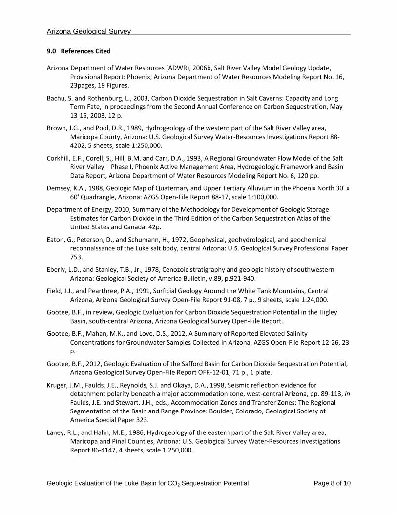
9.0 References Cited
Arizona Department of Water Resources (ADWR), 2006b, Salt River Valley Model Geology Update, Provisional Report: Phoenix, Arizona Department of Water Resources Modeling Report No. 16, 23pages, 19 Figures.
Bachu, S. and Rothenburg, L., 2003, Carbon Dioxide Sequestration in Salt Caverns: Capacity and Long Term Fate, in proceedings from the Second Annual Conference on Carbon Sequestration, May 13-15, 2003, 12 p.
Brown, J.G., and Pool, D.R., 1989, Hydrogeology of the western part of the Salt River Valley area, Maricopa County, Arizona: U.S. Geological Survey Water-Resources Investigations Report 88-4202, 5 sheets, scale 1:250,000.
Corkhill, E.F., Corell, S., Hill, B.M. and Carr, D.A., 1993, A Regional Groundwater Flow Model of the Salt River Valley – Phase I, Phoenix Active Management Area, Hydrogeologic Framework and Basin Data Report, Arizona Department of Water Resources Modeling Report No. 6, 120 pp.
Demsey, K.A., 1988, Geologic Map of Quaternary and Upper Tertiary Alluvium in the Phoenix North 30' x 60' Quadrangle, Arizona: AZGS Open-File Report 88-17, scale 1:100,000.
Department of Energy, 2010, Summary of the Methodology for Development of Geologic Storage Estimates for Carbon Dioxide in the Third Edition of the Carbon Sequestration Atlas of the United States and Canada. 42p.
Eaton, G., Peterson, D., and Schumann, H., 1972, Geophysical, geohydrological, and geochemical reconnaissance of the Luke salt body, central Arizona: U.S. Geological Survey Professional Paper 753.
Eberly, L.D., and Stanley, T.B., Jr., 1978, Cenozoic stratigraphy and geologic history of southwestern Arizona: Geological Society of America Bulletin, v.89, p.921-940.
Field, J.J., and Pearthree, P.A., 1991, Surficial Geology Around the White Tank Mountains, Central Arizona, Arizona Geological Survey Open-File Report 91-08, 7 p., 9 sheets, scale 1:24,000.
Gootee, B.F., in review, Geologic Evaluation for Carbon Dioxide Sequestration Potential in the Higley Basin, south-central Arizona, Arizona Geological Survey Open-File Report.
Gootee, B.F., Mahan, M.K., and Love, D.S., 2012, A Summary of Reported Elevated Salinity Concentrations for Groundwater Samples Collected in Arizona, AZGS Open-File Report 12-26, 23 p.
Gootee, B.F., 2012, Geologic Evaluation of the Safford Basin for Carbon Dioxide Sequestration Potential, Arizona Geological Survey Open-File Report OFR-12-01, 71 p., 1 plate.
Kruger, J.M., Faulds. J.E., Reynolds, S.J. and Okaya, D.A., 1998, Seismic reflection evidence for detachment polarity beneath a major accommodation zone, west-central Arizona, pp. 89-113, in Faulds, J.E. and Stewart, J.H., eds., Accommodation Zones and Transfer Zones: The Regional Segmentation of the Basin and Range Province: Boulder, Colorado, Geological Society of America Special Paper 323.
Laney, R.L., and Hahn, M.E., 1986, Hydrogeology of the eastern part of the Salt River Valley area, Maricopa and Pinal Counties, Arizona: U.S. Geological Survey Water-Resources Investigations Report 86-4147, 4 sheets, scale 1:250,000.

Arizona Geological Survey
Geologic Evaluation of the Luke Basin for CO2 Sequestration Potential Page 9 of 10
Menges, C.M., and Pearthree, P.A., 1989, Late Cenozoic tectonism in Arizona and its impact on regional landscape evolution, in Jenny, J.P. and Reynolds, S.J., eds., Geologic evolution of Arizona: Tucson, Arizona Geological Society Digest XVII, p. 649-680.
Oppenheimer, J.M., and Sumner, J.S., 1980, Depth-to-bedrock map, Basin and Range province, Arizona: Tucson, University of Arizona, Department of Geosciences, Laboratory of Geophysics, 1 sheet, scale 1:1,000,000 (available as Arizona Geological Survey publication NP-14).
Péwé, T.L., Wellendorf, C.S., and Bales, J.T., 1986, Environmental geology of the Tempe quadrangle, Maricopa County, Arizona: Arizona Bureau of Geology and Mineral Technology Geologic Investigation Folio Series no. 2, 8 sheets, scales 1:8,700 and 1:24,000.
Peirce, H.W., 1984, Some late Cenozoic basins and basin deposits of southern and western Arizona, in Smiley, T.L., Nations, J.D., Péwé, T.L., and Schafer, J.P., eds., Landscapes of Arizona - The geological story: Lanham, Md., University Press of America, p.207-227.
Rauzi, S., 1991, Clues point to oil in Arizona’s deep Tertiary, Oil and Gas Journal, pp. 107-118.
Rauzi, S.L., 2001, Arizona Has Oil and Gas Potential!, Arizona Geological Survey Circular 29, 40 p.
Rauzi, S.L., 2002a, Luke salt deposit: Arizona Geological Survey, Map 36, 1 sheet, scale 1:63,360.
Rauzi, S.L., 2002b, Arizona Has Salt!, Arizona Geological Survey Circular 30, 37 p.
Reeter, R.W., and Remick, W.H., 1986, Maps showing groundwater conditions in the West Salt River, East Salt River, Lake Pleasant, Carefree and Fountain Hills Subbasins of the Phoenix Active Management Area, Maricopa, Pinal, and Yavapai Counties, Arizona - 1983: Arizona Department of Water Resources Hydrologic Map Series Report no. 12, 3 sheets, scale 1:125,000.
Reynolds, S.J., 1985, Geology of the South Mountains, Central Arizona: Arizona Geological Survey Bulletin 195, 1 plate, 61 p.
Reynolds, S.J., and Bartlett, R.D., 2002, Subsurface geology of the easternmost Phoenix basin, Arizona: Implications for groundwater flow: Arizona Geological Survey Contributed Report CR-02-A, 72 p.
Richard, S.M., Reynolds, S.J., Spencer, J.E., and Pearthree, P.A., 2000, Geologic Map of Arizona: Tucson, Arizona Geo-logical Survey Map 35, 1 sheet, scale 1:1,000,000.
Richard, S.M., Shipman, T.C., Greene, Lizbeth, Harris, R.C., 2007, Estimated Depth to Bedrock in Arizona: Tucson, Arizona Geological Survey Digital Geologic Map 52 (DGM-52), version 1.0, 1 Adobe Acrobat (PDF) file (8 p., 1 sheet), design scale 1:1,000,000.
Saltus, R.W., and Jachens, R.C., 1995, Gravity and basin-depth maps of the Basin and Range Province, Western United States, Geophysical Investigations Map, GP-1012, p., 1 sheet, scale 1:2,500,000.
Scarborough, R.B., and Peirce, H.W., 1978, Late Cenozoic basins of Arizona, in Callender, J.F., Wilt, J.C., and Clemons, R.E., eds., Land of Cochise: New Mexico Geological Society 29th Field Conference Guidebook, p. 253-259.
Schumann, H.H., and O'Day, C.M., 1995, Investigation of hydrogeology, land subsidence, and earth-fissures, Luke Air Force Base, Arizona: U.S. Geological Survey Administrative Report, 62 p. [available for inspection at Arizona Geological Survey, 416 W. Congress, Suite 100, Tucson, Ariz.].
Spencer, J.E., and Reynolds, S.J., 1989, Middle Tertiary tectonics of Arizona and adjacent areas, in Jenney, J.P., and Reynolds, S.J., eds., Geologic evolution of Arizona: Tucson, Arizona Geological Society Digest XVII, p. 539-574.

Arizona Geological Survey
Geologic Evaluation of the Luke Basin for CO2 Sequestration Potential Page 10 of 10
Spencer, J.E., 2011, Preliminary Evaluation of Cenozoic Basins in Arizona for CO2 Sequestration Potential, Arizona Geological Survey, Open-File Report OFR 11-05, 15 p.
Spencer, J.E. and Rauzi, S.L., 2005, Drill holes in the Luke Salt Body penetrate underlying fault: Arizona Geology, v. 35, no. 3 (Fall 2005), p. 1-4.
Warren, M.B., 2009, Segmentation And Termination Of Low-Angle Normal Fault Domains: Insight From Higley Basin And Vicinity, Central Arizona, unpublished M.S., 39 p.

![J. - AZGS Document Repositoryrepository.azgs.az.gov/sites/default/files/dlio/files/... · 2010-08-24 · n LJ Late Tertiary basin-fill r_51~]' Middle Proterozoic granite (Yg) deposits](https://img.pdfslide.us/doc/110x75/5f082d977e708231d420ba32/j-azgs-document-2010-08-24-n-lj-late-tertiary-basin-fill-r51-middle-proterozoic.jpg)