Embed Size (px)
Citation preview

DAKOTA
SOUTH
STATE OFPROJECT
SHEETSHEETS
TOTAL
34 3532
1011
131415
22 23 24
5
8
1718
19
EDGEMONT18
471
FAS
FAS
20
3432
1011
131415
22 23 24
5
8
1718
19
EDGEMONT18
471
FAS
FAS
20
35
12/11/2014Plotting Date:
trrc
11628
1:2
00
Plotted Fro
m -
Plot Scale -
File -
...\Section S\0
2S8_title.d
gn
INDEX OF SHEETS
R 2 E
BRF 018P(02)13
MRM 13.40 + 0.000Structure No. 24 - 118 - 119
R 3 E
P 0471(08)27
MRM 27.29 +0.000Structure No. 24 -116 - 133
R 2 E
Cotton
wood C
reek
R 2 E R 3 E
18P
Cheyen
ne Riv
erT 8 S
R 2 E
T 9 S
T 9 S
T 8 S
Section S: Permanent Signing Plans
Standard PlatesS8-S10
Typical Sign LayoutsS5-S7
Estimate With General Notes & TablesS2-S4
General Layout W/IndexS1
BRF 018P(02)13 P 0471(08)27 S1 S10
PROJECT STATE OF SOUTH
DAKOTA
BRF 018P(02)13 P 0471(08)27
SHEET NO.
S2 S10
TOTAL SHEETS
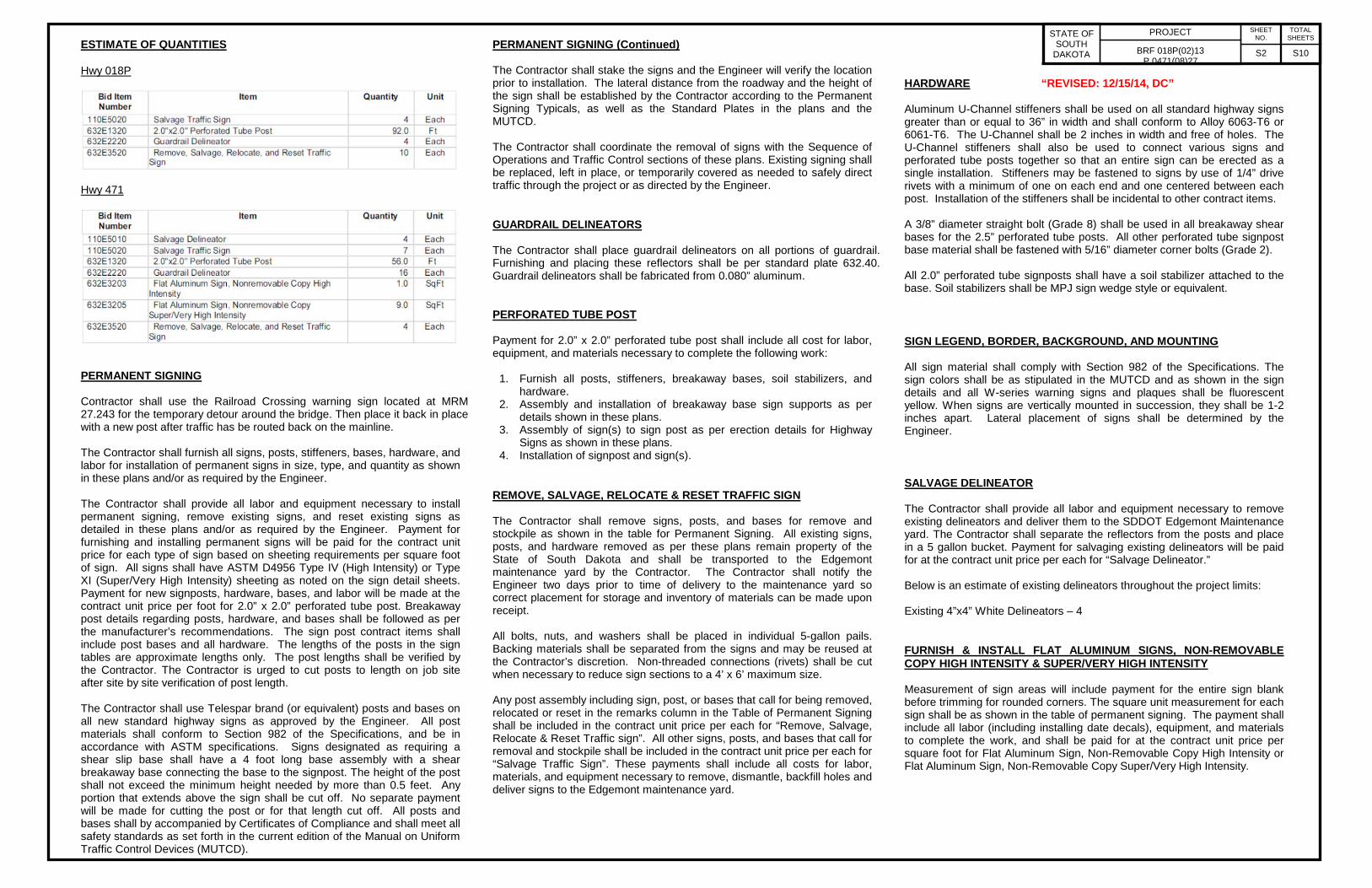
ESTIMATE OF QUANTITIES Hwy 018P
Hwy 471
PERMANENT SIGNING Contractor shall use the Railroad Crossing warning sign located at MRM 27.243 for the temporary detour around the bridge. Then place it back in place with a new post after traffic has be routed back on the mainline. The Contractor shall furnish all signs, posts, stiffeners, bases, hardware, and labor for installation of permanent signs in size, type, and quantity as shown in these plans and/or as required by the Engineer. The Contractor shall provide all labor and equipment necessary to install permanent signing, remove existing signs, and reset existing signs as detailed in these plans and/or as required by the Engineer. Payment for furnishing and installing permanent signs will be paid for the contract unit price for each type of sign based on sheeting requirements per square foot of sign. All signs shall have ASTM D4956 Type IV (High Intensity) or Type XI (Super/Very High Intensity) sheeting as noted on the sign detail sheets. Payment for new signposts, hardware, bases, and labor will be made at the contract unit price per foot for 2.0” x 2.0” perforated tube post. Breakaway post details regarding posts, hardware, and bases shall be followed as per the manufacturer’s recommendations. The sign post contract items shall include post bases and all hardware. The lengths of the posts in the sign tables are approximate lengths only. The post lengths shall be verified by the Contractor. The Contractor is urged to cut posts to length on job site after site by site verification of post length. The Contractor shall use Telespar brand (or equivalent) posts and bases on all new standard highway signs as approved by the Engineer. All post materials shall conform to Section 982 of the Specifications, and be in accordance with ASTM specifications. Signs designated as requiring a shear slip base shall have a 4 foot long base assembly with a shear breakaway base connecting the base to the signpost. The height of the post shall not exceed the minimum height needed by more than 0.5 feet. Any portion that extends above the sign shall be cut off. No separate payment will be made for cutting the post or for that length cut off. All posts and bases shall by accompanied by Certificates of Compliance and shall meet all safety standards as set forth in the current edition of the Manual on Uniform Traffic Control Devices (MUTCD).
PERMANENT SIGNING (Continued) The Contractor shall stake the signs and the Engineer will verify the location prior to installation. The lateral distance from the roadway and the height of the sign shall be established by the Contractor according to the Permanent Signing Typicals, as well as the Standard Plates in the plans and the MUTCD. The Contractor shall coordinate the removal of signs with the Sequence of Operations and Traffic Control sections of these plans. Existing signing shall be replaced, left in place, or temporarily covered as needed to safely direct traffic through the project or as directed by the Engineer. GUARDRAIL DELINEATORS The Contractor shall place guardrail delineators on all portions of guardrail. Furnishing and placing these reflectors shall be per standard plate 632.40. Guardrail delineators shall be fabricated from 0.080” aluminum. PERFORATED TUBE POST Payment for 2.0” x 2.0” perforated tube post shall include all cost for labor, equipment, and materials necessary to complete the following work:
1. Furnish all posts, stiffeners, breakaway bases, soil stabilizers, and hardware.
2. Assembly and installation of breakaway base sign supports as per details shown in these plans.
3. Assembly of sign(s) to sign post as per erection details for Highway Signs as shown in these plans.
4. Installation of signpost and sign(s). REMOVE, SALVAGE, RELOCATE & RESET TRAFFIC SIGN The Contractor shall remove signs, posts, and bases for remove and stockpile as shown in the table for Permanent Signing. All existing signs, posts, and hardware removed as per these plans remain property of the State of South Dakota and shall be transported to the Edgemont maintenance yard by the Contractor. The Contractor shall notify the Engineer two days prior to time of delivery to the maintenance yard so correct placement for storage and inventory of materials can be made upon receipt. All bolts, nuts, and washers shall be placed in individual 5-gallon pails. Backing materials shall be separated from the signs and may be reused at the Contractor’s discretion. Non-threaded connections (rivets) shall be cut when necessary to reduce sign sections to a 4’ x 6’ maximum size. Any post assembly including sign, post, or bases that call for being removed, relocated or reset in the remarks column in the Table of Permanent Signing shall be included in the contract unit price per each for “Remove, Salvage, Relocate & Reset Traffic sign”. All other signs, posts, and bases that call for removal and stockpile shall be included in the contract unit price per each for “Salvage Traffic Sign”. These payments shall include all costs for labor, materials, and equipment necessary to remove, dismantle, backfill holes and deliver signs to the Edgemont maintenance yard.
HARDWARE “REVISED: 12/15/14, DC” Aluminum U-Channel stiffeners shall be used on all standard highway signs greater than or equal to 36” in width and shall conform to Alloy 6063-T6 or 6061-T6. The U-Channel shall be 2 inches in width and free of holes. The U-Channel stiffeners shall also be used to connect various signs and perforated tube posts together so that an entire sign can be erected as a single installation. Stiffeners may be fastened to signs by use of 1/4” drive rivets with a minimum of one on each end and one centered between each post. Installation of the stiffeners shall be incidental to other contract items. A 3/8” diameter straight bolt (Grade 8) shall be used in all breakaway shear bases for the 2.5” perforated tube posts. All other perforated tube signpost base material shall be fastened with 5/16” diameter corner bolts (Grade 2). All 2.0” perforated tube signposts shall have a soil stabilizer attached to the base. Soil stabilizers shall be MPJ sign wedge style or equivalent. SIGN LEGEND, BORDER, BACKGROUND, AND MOUNTING All sign material shall comply with Section 982 of the Specifications. The sign colors shall be as stipulated in the MUTCD and as shown in the sign details and all W-series warning signs and plaques shall be fluorescent yellow. When signs are vertically mounted in succession, they shall be 1-2 inches apart. Lateral placement of signs shall be determined by the Engineer. SALVAGE DELINEATOR The Contractor shall provide all labor and equipment necessary to remove existing delineators and deliver them to the SDDOT Edgemont Maintenance yard. The Contractor shall separate the reflectors from the posts and place in a 5 gallon bucket. Payment for salvaging existing delineators will be paid for at the contract unit price per each for “Salvage Delineator.” Below is an estimate of existing delineators throughout the project limits: Existing 4”x4” White Delineators – 4 FURNISH & INSTALL FLAT ALUMINUM SIGNS, NON-REMOVABLE COPY HIGH INTENSITY & SUPER/VERY HIGH INTENSITY Measurement of sign areas will include payment for the entire sign blank before trimming for rounded corners. The square unit measurement for each sign shall be as shown in the table of permanent signing. The payment shall include all labor (including installing date decals), equipment, and materials to complete the work, and shall be paid for at the contract unit price per square foot for Flat Aluminum Sign, Non-Removable Copy High Intensity or Flat Aluminum Sign, Non-Removable Copy Super/Very High Intensity.

PROJECT STATE OF SOUTH
DAKOTA
BRF 018P(02)13 P 0471(08)27
SHEET NO.
S3 S10
TOTAL SHEETS
SHEETING REQUIREMENTS All legend and border utilizing the color black shall be vinyl or screen printed black, non-reflectorized material. All other legend and border shall be of same type of sheeting as the background of the same sign. All signs in the table for permanent signing that call for “Type IV” sheeting shall have High Intensity Prismatic retro-reflective background, Type IV as per AASHTO designation M 268 (ASTM D4956). All signs in the table for permanent signing that call for “Type XI” shall have micro-cube corner prismatic reflectorized background, Type XI as per AASHTO designation M 268 (ASTM D4956). DATE DECAL The Contractor shall affix a state furnished date decal to each new sign installed. Each decal is an approximately 2” X 2” self-adhesive sticker with removable paper backing and black numerals on a white background. The date decal displays the last two digits of the year the sign was manufactured (as illustrated). One decal shall be placed in the extreme lower left corner of the back of flat aluminum signs. Sign supports or other obstructions shall not block the view of the date decal upon completion of the sign installation. Cost for installing of date decal on new signs shall be incidental to the contract unit price for the various signing bid items.
15

DAKOTA
SOUTH
STATE OFPROJECT
SHEETSHEETS
TOTAL
...\02S8_SectionS
Notes
&Tables.d
gn
File -
Plotting Date: 11/20/2014
Plot Scale -
1:2
00
Plotted Fro
m -
trrc
11628
BRF 018P(02)13 P 0471(08)27 S4 S10

DAKOTA
SOUTH
STATE OFPROJECT
SHEETSHEETS
TOTAL
Variable Slope
bases.
of 2 1/4 " or larger.
using a tubular post size
base shall be used when
This style of breakaway
Stiffeners
U-Channel
Aluminum
bases.
bases.
larger)
36"x36" or
(on signs
Stiffeners
U-Channel
Aluminum
larger)
36"x36" or
(on signs
Stiffeners
U-Channel
Aluminum
(Drawing shown from face of sign)
WARNING SIGN
Variable Slope
Above Edge of Driving Lane
7’ (Urban/Interstate)
5’ (Rural) or
Above Edge of Driving Lane
6’ (Urban/Interstate)
4’ (Rural) or
(Drawing shown from face of sign)
WARNING SIGN WITH SUPPLEMENTAL SIGN
Ground Line
60’’ 4’’
max.
chordline
Anchor Post
Top of
Variable Slope
(Drawing shown from face of sign)
RECTANGULAR OR SQUARE SIGN > 36" IN WIDTH
(Drawing shown from face of sign)
RECTANGULAR OR SQUARE SIGN < 36" IN WIDTH
Above Edge of Driving Lane
7’ (Urban/Interstate)
5’ (Rural) or
Above Edge of Driving Lane
7’ (Urban/Interstate)
5’ (Rural) or
Variable Slope
1/5
W
3/5
W
1/5
W
Ground Line
60’’ 4’’
max.
chordline
Anchor Post
Top of
Ground Line
60’’ 4’’
max.
chordline
SupportBreakawayStub of
16’
3"
3"
16’
7’ Minimum
2"
7’ Minimum
16’
3"
3"
7’ Minimum
16’
2"
TYPICAL ERECTION DETAILS FOR WARNING SIGNS OR RECTANGULAR SIGNSTYPICAL ERECTION DETAILS FOR SQUARE
Ground Line
Ground Line
Top of Inslope
Top of Inslope
Ground Line
Ground Line
Top of Inslope
Top of Inslope
See detail sheets for bases.
See detail sheets forSee detail sheets for
See detail sheets for
...\02S8_Sig
nSupportSta
ndards.d
gn
File -
Plotting Date: 11/20/2014
Plot Scale -
1:2
00
Plotted Fro
m -
trrc
11628
BRF 018P(02)13 P 0471(08)27 S5 S10

DAKOTA
SOUTH
STATE OFPROJECT
SHEETSHEETS
TOTAL
for bases.
StiffenersU-ChannelAluminum
Variable Slope
1/5
W
3/5
W
1/5
W
Variable Slope
(Drawing shown from face of sign)
(Drawing shown from face of sign)
tubular post size of 2 1/4 " or larger.
shall be used when using a
This style of breakaway base
Above Edge of Driving Lane
5’ (Rural) or 7’ (Urban)
Above Edge of Driving Lane
5’ (Rural) or 7’ (Urban)
TWO-POST ASSEMBLY
SINGLE-POST ASSEMBLY
Ground Line
60’’ 4’’
max.
chordline
Anchor Post
Top of
Ground Line
60’’ 4’’
max.
chordline
SupportBreakawayStub of
30"
3"
7’ Minimum
12’
36,48, or 60"
12’
7’ Minimum
2"
Variable
Slope
5" From Edge of Driving Lane
6.5" 29" 9"
44.5"
3"
36"
7’ Minimum
16’
Ground Line
(Drawing shown from face of sign)
Top of Inslope
Ground Line
60’’ 4’’
max.
chordline
Anchor Post
Top of
See Detail Sheets for Bases
TYPICAL ERECTION DETAILS FOR STOP SIGNS
Edge of Driving Lane
Ground Line
Ground Line
Edge of Driving Lane
Top of Inslope
Top of Inslope
See detail sheets for bases.
See detail sheets
NO PASSING ZONE PENNANTTYPICAL ERECTION DETAILS FOR
...\02S8_Sig
nSupportSta
ndards.d
gn
File -
Plotting Date: 11/20/2014
Plot Scale -
1:2
00
Plotted Fro
m -
trrc
11628
BRF 018P(02)13 P 0471(08)27 S6 S10
DAKOTA
SOUTH
STATE OFPROJECT
SHEETSHEETS
TOTAL
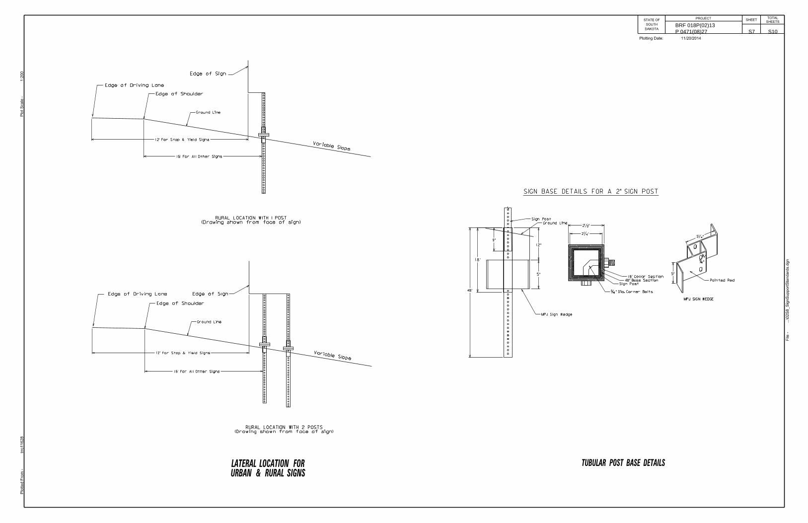
2�"
2�"
48"
12"
5"
5�"
9"
12’ For Stop & Yield Signs
12’ For Stop & Yield Signs
16’ For All Other Signs
16’ For All Other Signs
5"
18"
URBAN & RURAL SIGNSLATERAL LOCATION FOR
SIGN BASE DETAILS FOR A 2" SIGN POST
MPJ SIGN WEDGE
�"
�"
TUBULAR POST BASE DETAILS
Variable Slope
Edge of Shoulder
(Drawing shown from face of sign)RURAL LOCATION WITH 2 POSTS
Variable Slope
Edge of Shoulder
Edge of Driving Lane
Edge of Sign
Edge of SignEdge of Driving Lane
(Drawing shown from face of sign)RURAL LOCATION WITH 1 POST
�" Dia. Corner Bolts
48" Base Section
Sign Post
Ground Line
MPJ Sign Wedge
18" Collar Section
Sign Post
Ground Line
Ground Line
Painted Red
...\02S8_Sig
nSupportSta
ndards.d
gn
File -
Plotting Date: 11/20/2014
Plot Scale -
1:2
00
Plotted Fro
m -
trrc
11628
BRF 018P(02)13 P 0471(08)27 S7 S10

11/20/2014Plotting Date:
trrc11628
1:200
5
Plotted
Fro
m -
Plot
Scale -
File - ...\02
S8_
Section
SStd
Plates1.dgn
Plot
Na
me -
DAKOTA
SOUTH
STATE OFPROJECT
SHEETSHEETS
TOTAL
BRF 018P(02)13 P 0471(08)27 S8 S10

11/20/2014Plotting Date:
trrc11628
1:200
6
Plotted
Fro
m -
Plot
Scale -
File - ...\02
S8_
Section
SStd
Plates1.dgn
Plot
Na
me -
DAKOTA
SOUTH
STATE OFPROJECT
SHEETSHEETS
TOTAL
BRF 018P(02)13 P 0471(08)27 S9 S10

DAKOTA
SOUTH
STATE OFPROJECT
SHEETSHEETS
TOTAL
11/20/2014Plotting Date:
trrc11628
1:200
4
Plotted
Fro
m -
Plot
Scale -
File - ...\02
S8_
Section
SStd
Plates1.dgn
Plot
Na
me -
BRF 018P(02)13 P 0471(08)27 S10 S10