Embed Size (px)
Citation preview
1
Shell U.K. Limited
Frontispiece: Brent Delta Topside in 2013.
Brent Delta Topside Decommissioning Close-out Report
Shell Report Number: BDE-D-TOP-AA-6945-00002 12th December 2019
Brent Delta Topside Decommissioning – Close-out Report
2
Contents
1 SUMMARY .................................................................................................................................. 6
1.1 Summary of Decommissioning Programme ................................................................................................ 6 1.1.1 Close -out Report ................................................................................................................................................ 6 1.1.2 Brent Delta Decommissioning ............................................................................................................................ 6
1.2 Schematic of Installation Being Decommissioned ..................................................................................... 10
1.3 Gantt chart / progress against approved schedule ................................................................................... 11
1.4 Associated Decommissioning Approvals ................................................................................................... 11
2 DECOMMISSIONING ACTIVITIES THIS PERIOD .......................................................................... 13
2.1 Organisation of the Work ......................................................................................................................... 13 2.1.1 Project Management and Verification ............................................................................................................. 13 2.1.2 Main Contractors and Their Role ..................................................................................................................... 13
2.2 Description of the Brent Delta Topside ..................................................................................................... 14 2.2.1 Introduction ......................................................................................................................................................... 14 2.2.2 Main Features ................................................................................................................................................... 16 2.2.3 Materials Received on Topside and their Fate ................................................................................................. 16
2.3 Preparation for Topside Removal ............................................................................................................. 19 2.3.1 Introduction ...................................................................................................................................................... 19 2.3.2 Plug and Make Safe Wells ................................................................................................................................ 19 2.3.3 Removal of Conductors and Pipework ............................................................................................................. 19 2.3.4 Preparation for Lift ........................................................................................................................................... 20 2.3.5 Cleaning of Topside Process facilities before Removal .................................................................................... 22 2.3.6 Cutting the Legs ................................................................................................................................................ 22 2.3.7 Removal of Attic Oil .......................................................................................................................................... 24 2.3.8 Unmanned Period ............................................................................................................................................ 24
2.4 Removal and Load-In of Topside ............................................................................................................... 25 2.4.1 Lifting the Topside ............................................................................................................................................ 25 2.4.2 Fitting Navigation Aids and Condition of the Brent Delta GBS after Removal of Topside ............................... 28 2.4.3 Transportation to Near Shore Transfer Site ..................................................................................................... 30 2.4.4 Transfer of Topside from SLV to ASP Facility .................................................................................................... 31
2.5 Dismantling and Recycling ........................................................................................................................ 37
2.5.1 Overview .................................................................................................................................................. 37
2.5.2 Surveys and preliminary work .................................................................................................................. 38
2.5.3 Dismantling the main structure ................................................................................................................ 38
2.6 Post-Topside Removal Activities Offshore ................................................................................................ 39 2.6.1 Information to Third-party Users of the Area .................................................................................................. 39 2.6.2 Monitoring and Maintenance .......................................................................................................................... 39 2.6.3 Post-Topside Removal Debris Clearance and Verification ............................................................................... 40
2.7 Key Milestones ......................................................................................................................................... 40
3 IMPACT ON ENVIRONMENT ..................................................................................................... 42
Brent Delta Topside Decommissioning – Close-out Report
3
3.1 Comparison with assumptions in the Environmental Impact Assessment ................................................ 42
4 IMPACT ON HEALTH AND SAFETY ............................................................................................ 43
4.1 Technical Safety ........................................................................................................................................ 43
4.2 Occupational Safety .................................................................................................................................. 43
5 LESSONS LEARNED ................................................................................................................... 44
5.1 In Planning and Preparation for Decommissioning ................................................................................... 44
5.2 In Operations to Remove and Dismantle .................................................................................................. 45
6 COST ........................................................................................................................................ 46
7 PHOTOGRAPHS ........................................................................................................................ 46
Brent Delta Topside Decommissioning – Close-out Report
4
Terms and Abbreviations
Abbreviation Explanation Abex Abandonment Expenditure Able Able UK Limited ACM Asbestos Containing Material Al Aluminium ALARP As Low as Reasonably Practicable AOR Attic Oil Recovery ASP Able Seaton Port AtoN Aids to Navigation BEIS Department for Business, Energy and Industrial Strategy Cd Cadmium Cop Cessation of Production Cu Copper DECC Department of Energy and Climate Change DP Decommissioning Programme DSC Decommissioning Services Contract DWC Diamond Wire Cutting DyP Dynamic Positioning EIA Environmental Impact Assessment EOFL End of Field Life EPFM Ethylene Propylene Diene Monomer (a type of rubber) ES Environmental Statement ESHIA Environmental, Societal, Health Impact Assessment Fe Iron FishSAFE An electronic means of alerting vessels to the proximity of a structure in the sea GBS Gravity Base Structure GRP Glass-Reinforced Plastic GSM Global System for Mobile [communication] H2S Hydrogen Sulphide HAZID Hazard Identification HSE Health, Safety and Environment HSSE Health, Safety, Security and Environment HVAC Heating, Ventilation and Air-Conditioning IA Impact Assessment IMDG International Maritime Dangerous Goods INCA Industry Nature Conservation Association JNCC Joint Nature Conservation Committee Km Kilometre LAT Lowest Astronomical Tide LSA Low Specific Activity (Scale) m Metre MAH Major Accident Hazard MCA Maritime and Coastguard Agency MCZ Marine Conservation Zone MMMF Man-Made Mineral Fibre MSF Module Support Frame

Brent Delta Topside Decommissioning – Close-out Report
5
Ni Nickel nm Nautical Mile NNR National Nature Reserve NORM Naturally Occurring Radioactive Material OPEX Operating Expenditure OPRED Offshore Petroleum Regulator for Environment and Decommissioning P&A Plug and Abandon P&L Plug and Lubricate OGA Oil and Gas Authority OPEP Oil Pollution Emergency Plan OSPAR Oslo Paris Commission OSRL Oil Spill Response Limited Pb Lead PCB Poly-Chloride Biphenyl PGDS Plate Girder Deck Structure POB Persons on Board PPE Personal Protective Equipment RMCZ Recommended Marine Conservation Zone RSA Radioactive Substances Act 1993. SCE Safety Critical Element SLV Single Lift Vessel SOPEP Shipboard Oil Pollution Emergency Plan SP Social Performance SSSI Site of Special Scientific Interest t Tonne (1,000kg) TLS Topside Lifting System UKHO United Kingdom Hydrographic Office UK HSE UK Health and Safety Executive WEEE Waste Electrical and Electronic Equipment WtE Waste to Energy
References AECOM, 2016. Brent Removals and Dismantlement Impact Assessment (ESHIA), BDE-F-TRM-HX-6873-00002.
BEIS, 2018. Guidance Notes: Decommissioning of Offshore Oil and Gas Installations and Pipelines, November 2018.
DNV GL, 2017. Brent Field Decommissioning Environmental Statement, BDE-F-GEN-HE-0702-00006.
Oil and Gas UK Limited, 2012. Guidelines for Suspension and Abandonment of Wells.
OSPAR, 1998. Decision 98/3 on the Disposal of Disused Offshore Installations. Ministerial meeting of the OSPAR commission – SINTRA: 22 – 23 July 1998.
Shell, 2015. Brent Delta Topside Decommissioning Programme, BDE-D-TOP-AA-5880-00001
Shell, 2017. Brent Field Decommissioning Programmes, BDE-F-GEN-AA-5880-00015.
Shell, 2017. Brent Bravo, Charlie and Delta GBS Decommissioning Technical Document, BDE-F-GBS-BA-5801-00001.
Shell, 2019. Brent Field Pipelines Decommissioning Programme, BDE-F-PIP-AA-5880-00002
Brent Delta Topside Decommissioning – Close-out Report
6
1 SUMMARY
1.1 Summary of Decommissioning Programme
1.1.1 Close -out Report
In accordance with the Petroleum Act 1998 and the BEIS Guidance Notes: Decommissioning of Offshore Oil and Gas Installations and Pipelines, the owners as Section 29 Notice holders sought approval from the Department for Business, Energy and Industrial Strategy (BEIS)1 via a Decommissioning Programme (DP) to decommission the Brent Delta topside by removing it completely and returning it to shore for reuse, recycling and disposal. The Brent Delta Topside Decommissioning Programme was approved on 3rd July 2015. This document is a final close-out report describing the offshore and onshore programmes of work to cut, lift, remove, dismantle, reuse, recycle and dispose of the Brent Delta topside. It is submitted by the co-venturers Shell U.K. Limited and Esso Exploration and Production UK Limited. This report also covers the work to fit concrete caps and Aids to Navigation (AtoN) on top of the legs of the gravity based structure (GBS). The report describes the programmes of work that were performed during the decommissioning process and provides explanations for any variations from the planned programmes. This report covers the period up to the end of the dismantling of the topside.
1.1.2 Brent Delta Decommissioning
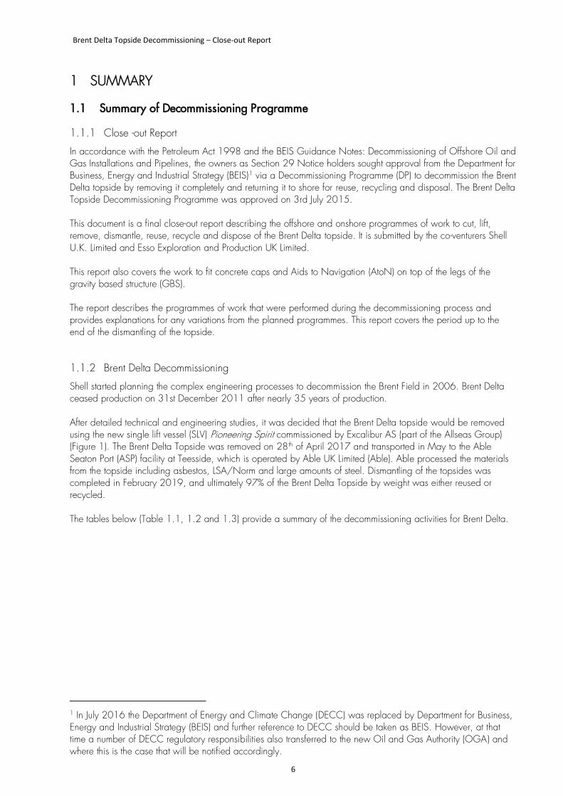
Shell started planning the complex engineering processes to decommission the Brent Field in 2006. Brent Delta ceased production on 31st December 2011 after nearly 35 years of production. After detailed technical and engineering studies, it was decided that the Brent Delta topside would be removed using the new single lift vessel (SLV) Pioneering Spirit commissioned by Excalibur AS (part of the Allseas Group) (Figure 1). The Brent Delta Topside was removed on 28th of April 2017 and transported in May to the Able Seaton Port (ASP) facility at Teesside, which is operated by Able UK Limited (Able). Able processed the materials from the topside including asbestos, LSA/Norm and large amounts of steel. Dismantling of the topsides was completed in February 2019, and ultimately 97% of the Brent Delta Topside by weight was either reused or recycled. The tables below (Table 1.1, 1.2 and 1.3) provide a summary of the decommissioning activities for Brent Delta.
1 In July 2016 the Department of Energy and Climate Change (DECC) was replaced by Department for Business, Energy and Industrial Strategy (BEIS) and further reference to DECC should be taken as BEIS. However, at that time a number of DECC regulatory responsibilities also transferred to the new Oil and Gas Authority (OGA) and where this is the case that will be notified accordingly.
Brent Delta Topside Decommissioning – Close-out Report
7
Figure 1. The SLV Pioneering Spirit with the Cargo Barge Iron Lady.
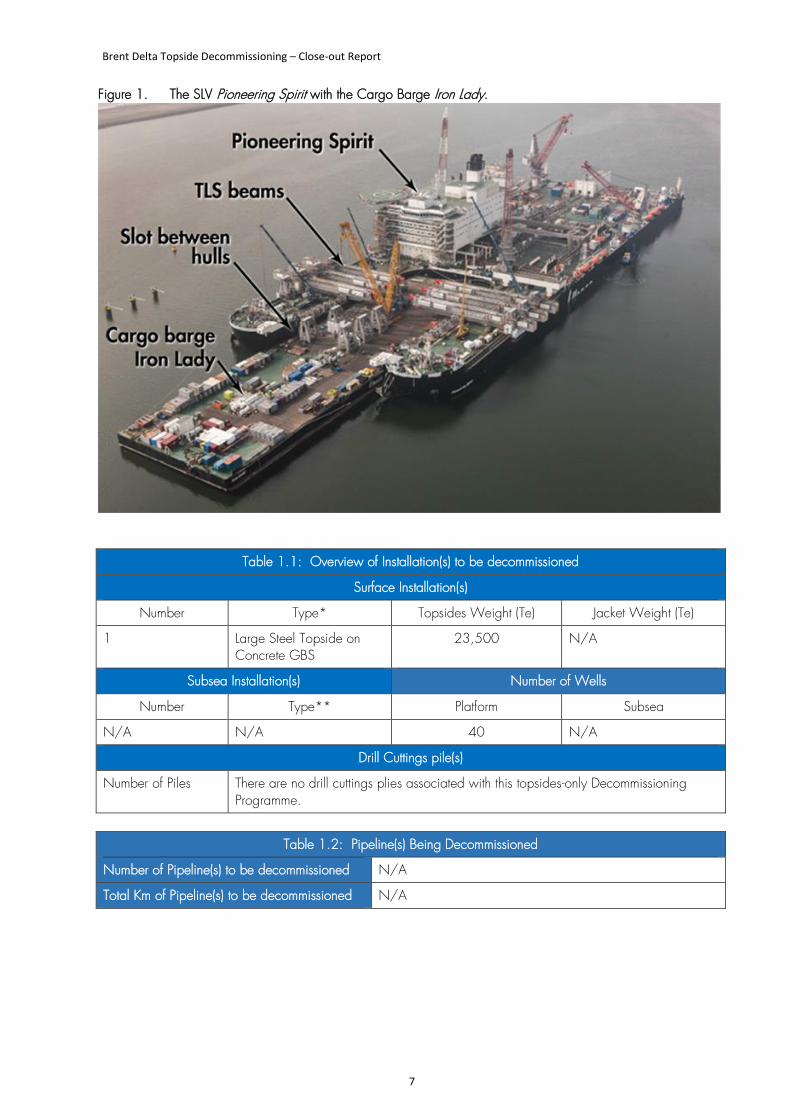
Table 1.1: Overview of Installation(s) to be decommissioned
Surface Installation(s)
Number Type* Topsides Weight (Te) Jacket Weight (Te)
1 Large Steel Topside on Concrete GBS
23,500 N/A
Subsea Installation(s) Number of Wells
Number Type** Platform Subsea
N/A N/A 40 N/A
Drill Cuttings pile(s)
Number of Piles There are no drill cuttings plies associated with this topsides-only Decommissioning Programme.
Table 1.2: Pipeline(s) Being Decommissioned
Number of Pipeline(s) to be decommissioned N/A
Total Km of Pipeline(s) to be decommissioned N/A
Brent Delta Topside Decommissioning – Close-out Report
8
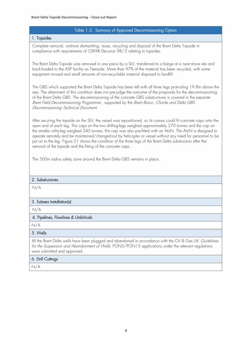
Table 1.3: Summary of Approved Decommissioning Option
1. Topsides
Complete removal, onshore dismantling, reuse, recycling and disposal of the Brent Delta Topside in compliance with requirements of OSPAR Decision 98/3 relating to topsides. The Brent Delta Topside was removed in one piece by a SLV, transferred to a barge at a near-shore site and back-loaded to the ASP facility as Teesside. More than 97% of the material has been recycled, with some equipment re-used and small amounts of non-recyclable material disposed to landfill. The GBS which supported the Brent Delta Topside has been left with all three legs protruding 19.8m above the sea. The attainment of this condition does not pre-judge the outcome of the proposals for the decommissioning of the Brent Delta GBS. The decommissioning of the concrete GBS substructures is covered in the separate Brent Field Decommissioning Programme , supported by the Brent Bravo, Charlie and Delta GBS Decommissioning Technical Document. After securing the topside on the SLV, the vessel was repositioned, so its cranes could fit concrete caps onto the open end of each leg. The caps on the two drilling-legs weighed approximately 270 tonnes and the cap on the smaller utility-leg weighed 240 tonnes; this cap was also pre-fitted with an AtoN. The AtoN is designed to operate remotely and be maintained/changed-out by helicopter or vessel without any need for personnel to be put on to the leg. Figure 21 shows the condition of the three legs of the Brent Delta substructure after the removal of the topside and the fitting of the concrete caps. The 500m radius safety zone around the Brent Delta GBS remains in place.
2. Substructures
N/A
3. Subsea Installation(s)
N/A
4. Pipelines, Flowlines & Umbilicals
N/A
5. Wells
All the Brent Delta wells have been plugged and abandoned in accordance with the Oil & Gas UK Guidelines for the Suspension and Abandonment of Wells. PON5/PON15 applications under the relevant regulations were submitted and approved.
6. Drill Cuttings
N/A
Brent Delta Topside Decommissioning – Close-out Report
9
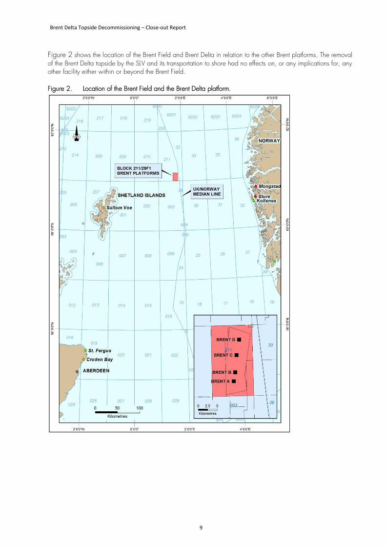
Figure 2 shows the location of the Brent Field and Brent Delta in relation to the other Brent platforms. The removal of the Brent Delta topside by the SLV and its transportation to shore had no effects on, or any implications for, any other facility either within or beyond the Brent Field. Figure 2. Location of the Brent Field and the Brent Delta platform.
Brent Delta Topside Decommissioning – Close-out Report
10
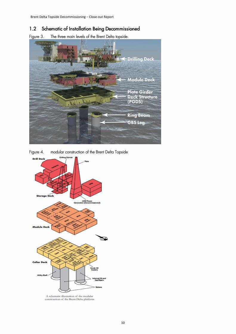
1.2 Schematic of Installation Being Decommissioned Figure 3. The three main levels of the Brent Delta topside.
Figure 4. modular construction of the Brent Delta Topside
Brent Delta Topside Decommissioning – Close-out Report
11
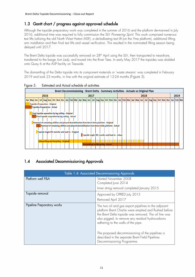
1.3 Gantt chart / progress against approved schedule Although the topside preparatory work was completed in the summer of 2016 and the platform de-manned in July 2016, additional time was required to fully commission the SLV Pioneering Spirit. This work comprised numerous test lifts (utilizing the old North West Hutton MSF), a de-ballasting test lift (on the Yme platform), additional lifting arm installation and then final test lifts and vessel verification. This resulted in the nominated lifting season being delayed until 2017. The Brent Delta topside was successfully removed on 28th April using the SLV, then transported to nearshore, transferred to the barge Iron Lady, and towed into the River Tees. In early May 2017 the topsides was skidded onto Quay 6 at the ASP facility on Teesside. The dismantling of the Delta topside into its component materials or ‘waste streams’ was completed in February 2019 and took 23 months, in line with the original estimate of 12-24 months (Figure 5).
Figure 5. Estimated and Actual schedule of activities
1.4 Associated Decommissioning Approvals
Table 1.4: Associated Decommissioning Approvals
Platform well P&A Started November 2008 Completed June 2014 Inner string removal completed January 2015
Topside removal Approved by OPRED July 2015 Removed April 2017
Pipeline Preparatory works The two oil and gas export pipelines to the adjacent platform Brent Charlie were emptied and flushed before the Brent Delta topside was removed. The oil line was also pigged, to remove any residual hydrocarbons adhering to the walls of the pipe. The proposed decommissioning of the pipelines is described in the separate Brent Field Pipelines Decommissioning Programme.
Brent Delta Topside Decommissioning – Close-out Report
12
This page is intentionally left blank
Brent Delta Topside Decommissioning – Close-out Report
13
2 DECOMMISSIONING ACTIVITIES THIS PERIOD
The key milestones for the decommissioning activities on the Brent Delta Topside are summarised below in Table 2.1.
Table 2.1: Decommissioning Activities this Period
Well P&A Completed June 2014
Conductor removal Completed January 2015
Topsides Preparation:
- Topside Preparation Start
- Leg Cutting
- Downman
Summer 2014 Summer 2016 Q3 2016
Topsides Lift Completed April 28th 2017
Load-In Completed May 7th 2017
Dismantling Completed February 2019
2.1 Organisation of the Work
2.1.1 Project Management and Verification
The project was managed in accordance with applicable regulatory requirements and to Shell’s Global Project Management standards. It was led by an experienced Shell Project Director with sub-project managers, project engineers and support functions including, but not limited, to Health, Safety and Environment (HSE), Quality, and Project Services. The project was divided into a series of sub-projects and tendered to the open market as appropriate. Synergies were sought with other Shell project activities (and in principle other decommissioning activities) where they made economic and business sense.
2.1.2 Main Contractors and Their Role
Shell concluded that there was a net economic advantage to be gained by tendering the Decommissioning Services Contract (DSC) scope as a dedicated contract. The DSC contract was awarded to PSN (Aberdeen) Ltd and started on 1st August 2010. The primary aim of the DSC was to support the topsides engineering-down activities, with the objective to shut down and make safe the Brent platforms once they reached Cessation of Production (CoP). As such, the contractor was expected to deliver the following Post-CoP scopes of work: -
• Platform maintenance (i.e. life support, utilities, fabric integrity).
• System decommissioning (i.e. cleaning, support to operations).
• Modifications (i.e. minor Change Proposals, design and installation of temporary equipment).
• Module separations (i.e. isolation, segregations).
The offshore removals contract was awarded to Excalibur AS (part of the Allseas Group) in 2013. Allseas were tasked with completing design work and engineering to ensure the topside was suitable for the single lift, as well as providing the interface between the single lift vessel and the disposal yard. The scope of the contract included the following:
Brent Delta Topside Decommissioning – Close-out Report
14
• Single lift design engineering and project management
• Leg cutting design and execution
• Lift of structure using Pioneering Spirit • Transport to barge transfer location
• Load in at disposal yard from barge The onshore dismantling and recycling contract was awarded to Able UK in 2013. The Onshore Disposal scope comprised the following:
• Provision of a suitable quayside facility and lay-down area to receive the topside.
• Provision of facilities, equipment and personnel to safely dismantle the topside.
• Re-use and/or recycling of materials, with a target of at least 97%.
• Disposal of debris in accordance with statutory requirements.
2.2 Description of the Brent Delta Topside
2.2.1 Introduction
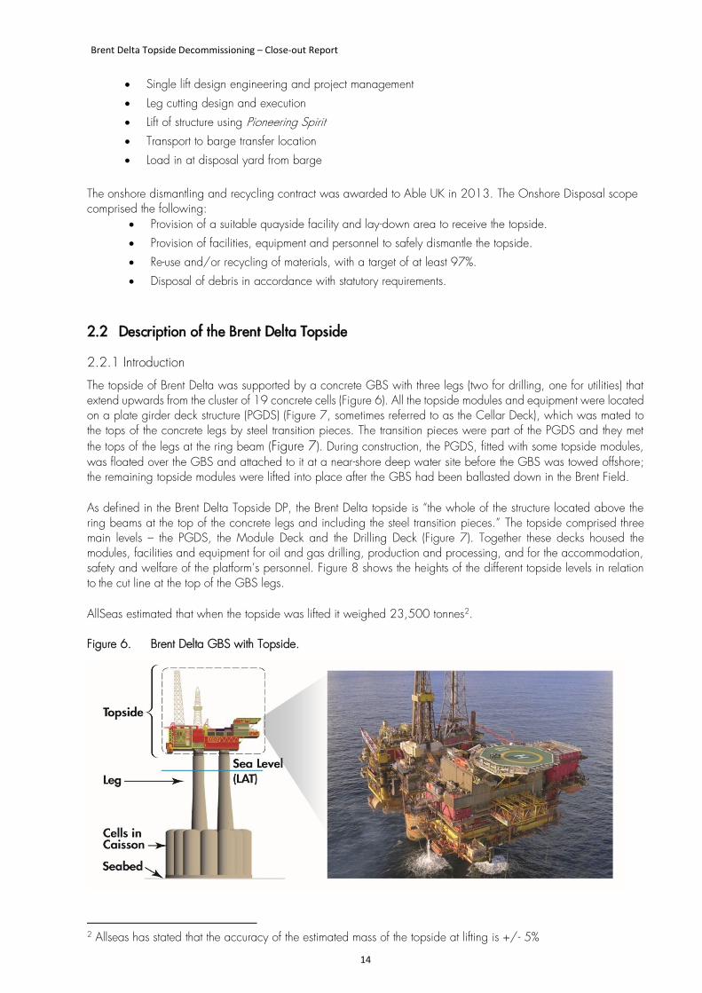
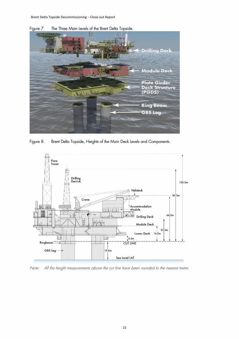
The topside of Brent Delta was supported by a concrete GBS with three legs (two for drilling, one for utilities) that extend upwards from the cluster of 19 concrete cells (Figure 6). All the topside modules and equipment were located on a plate girder deck structure (PGDS) (Figure 7, sometimes referred to as the Cellar Deck), which was mated to the tops of the concrete legs by steel transition pieces. The transition pieces were part of the PGDS and they met the tops of the legs at the ring beam (Figure 7). During construction, the PGDS, fitted with some topside modules, was floated over the GBS and attached to it at a near-shore deep water site before the GBS was towed offshore; the remaining topside modules were lifted into place after the GBS had been ballasted down in the Brent Field. As defined in the Brent Delta Topside DP, the Brent Delta topside is “the whole of the structure located above the ring beams at the top of the concrete legs and including the steel transition pieces.” The topside comprised three main levels – the PGDS, the Module Deck and the Drilling Deck (Figure 7). Together these decks housed the modules, facilities and equipment for oil and gas drilling, production and processing, and for the accommodation, safety and welfare of the platform’s personnel. Figure 8 shows the heights of the different topside levels in relation to the cut line at the top of the GBS legs. AllSeas estimated that when the topside was lifted it weighed 23,500 tonnes2. Figure 6. Brent Delta GBS with Topside.
2 Allseas has stated that the accuracy of the estimated mass of the topside at lifting is +/- 5%
Brent Delta Topside Decommissioning – Close-out Report
15
Figure 7. The Three Main Levels of the Brent Delta Topside.
Figure 8. Brent Delta Topside, Heights of the Main Deck Levels and Components.
Note: All the height measurements above the cut line have been rounded to the nearest metre.
Brent Delta Topside Decommissioning – Close-out Report
16
2.2.2 Main Features
The Brent Delta topside housed the following modules and systems:
• Accommodation and helideck. Comprised the accommodation, laundry, catering, and recreation facilities for the crew. Helicopter landing and fuelling facilities were located on the roof of this module.
• Drilling derrick and support. Comprised equipment for the drilling and maintenance of oil and gas wells, including the drilling rig, an electrical generation package and facilities for the bulk storage, handling, preparation and pumping of drilling fluids.
• Utilities. Comprised the firewater and safety systems, water purifying equipment, chemical storage and pumping, potable water bulk storage and pumping, hot water boilers, electrical switchboards, workshop facilities, and diesel fuel storage and pumping.
• Oil and Gas production process modules. Contained all of the vessels and equipment used to separate the well fluid into its three main components – oil, gas and produced water – and transfer these individual streams to the export pipelines, other areas of the platform or for permitted disposal via the oil storage cells as produced water.
• Water injection module. Contained the equipment used to filter and treat raw seawater so that it could be pumped down-hole to enhance production by augmenting the natural pressure of the reservoir.
• Power generation modules. Contained the electrical generators, transformers, switchboards and associated equipment. The generators were powered by turbines fuelled by gas from the production process. After CoP Brent Delta was powered exclusively by diesel generators.
• Wellhead modules. Contained the equipment and control valves that regulated the flow of oil and gas from each of the individual wells. The individual flow lines were combined via a manifold system which in turn supplied the oil and gas processing equipment. The modules also contained the water injection wellhead equipment which, when in use, received high pressure treated water from the water injection module and routed it to the dedicated water injection wells and down into the reservoir.
• Flare tower. The tower supported the flare, which was designed to vent and burn any surplus hydrocarbon gas that might pose safety risks to platform personnel and process systems. Following CoP and removal of the hydrocarbon inventory, the flare was only used for cold-venting.
• Drainage systems. The drains on the Brent Delta platform were divided into those serving hazardous areas, non-hazardous areas and living quarters. They were used to manage permitted discharges to sea through the use of oil/water separators.
•
2.2.3 Materials Received on Topside and their Fate
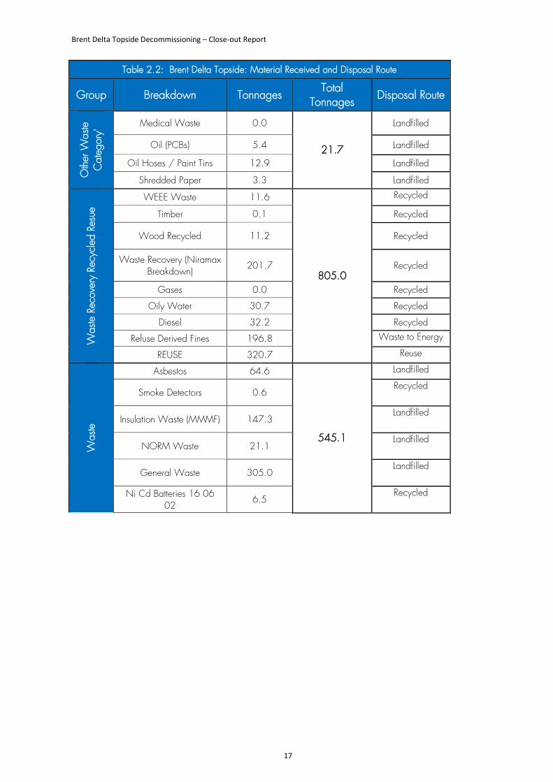
Table 2.2 provides an inventory of the materials that were found to be present on the Brent Delta topside during dismantlement at the ASP facility, and identifies the method used to treat, manage or dispose of them. The topside materials and components are categorised according to the nomenclature and codes used by the dismantling contractor. Together, ferrous steel and stainless steel accounted for approximately 90% of the mass of the topside.
The total mass of material recovered in the topside, 23,560 tonnes, is approximately 600 tonnes (<3%) less than the mass estimated in the Brent Delta Topside Decommissioning DP. This appears to be the result mainly of over-estimates of copper-nickel alloys and stainless steel.
Brent Delta Topside Decommissioning – Close-out Report
17
Table 2.2: Brent Delta Topside: Material Received and Disposal Route
Group Breakdown Tonnages Total
Tonnages Disposal Route
Oth
er W
aste
C
ateg
ory'
Medical Waste 0.0
21.7
Landfilled
Oil (PCBs) 5.4 Landfilled
Oil Hoses / Paint Tins 12.9 Landfilled
Shredded Paper 3.3 Landfilled
Was
te R
ecov
ery
Recy
cled
Res
ue
WEEE Waste 11.6
805.0
Recycled
Timber 0.1 Recycled
Wood Recycled 11.2 Recycled
Waste Recovery (Niramax Breakdown)
201.7 Recycled
Gases 0.0 Recycled Oily Water 30.7 Recycled
Diesel 32.2 Recycled Refuse Derived Fines 196.8 Waste to Energy
REUSE 320.7 Reuse
Was
te
Asbestos 64.6
545.1
Landfilled
Smoke Detectors 0.6 Recycled
Insulation Waste (MMMF) 147.3 Landfilled
NORM Waste 21.1 Landfilled
General Waste 305.0 Landfilled
Ni Cd Batteries 16 06 02
6.5 Recycled
Brent Delta Topside Decommissioning – Close-out Report
18
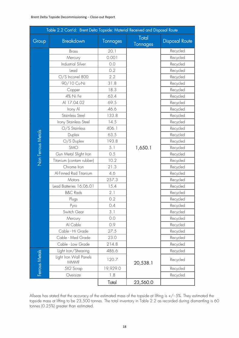
Table 2.2 Cont’d: Brent Delta Topside: Material Received and Disposal Route
Group Breakdown Tonnages Total
Tonnages Disposal Route
Non
Fer
rous
Met
als
Brass 20.1
1,650.1
Recycled
Mercury 0.001 Recycled Industrial Silver 0.0 Recycled
Lead 0.2 Recycled O/S Inconel 800 2.2 Recycled
90/10 Cu-Ni 31.8 Recycled Copper 18.3 Recycled
4% Ni Fe 63.4 Recycled Al 17.04.02 69.5 Recycled
Irony Al 46.6 Recycled Stainless Steel 133.8 Recycled
Irony Stainless Steel 14.5 Recycled O/S Stainless 406.1 Recycled
Duplex 63.5 Recycled O/S Duplex 193.8 Recycled
SMO 5.1 Recycled Gun Metal Slight Iron 0.5 Recycled
Titanium (contam rubber) 10.2 Recycled Chrome Iron 21.3 Recycled
Al-Finned Rad Titanium 4.6 Recycled Motors 257.3 Recycled
Lead Batteries 16.06.01 15.4 Recycled B&C Rads 2.1 Recycled
Plugs 0.2 Recycled Pyro 0.4 Recycled
Switch Gear 3.1 Recycled Mercury 0.0 Recycled Al Cable 0.9 Recycled
Cable - Hi Grade 27.5 Recycled Cable - Med Grade 23.0 Recycled Cable - Low Grade 214.8 Recycled
Ferro
us M
etal
s Light Iron/Shearing 486.6
20,538.1
Recycled Light Iron Wall Panels
MMMF 120.7 Recycled
5X2 Scrap 19,929.0 Recycled Oversize 1.8 Recycled
Total 23,560.0
Allseas has stated that the accuracy of the estimated mass of the topside at lifting is +/- 5%. They estimated the topside mass at lifting to be 23,500 tonnes. The total inventory in Table 2.2 as recorded during dismantling is 60 tonnes (0.25%) greater than estimated.
Brent Delta Topside Decommissioning – Close-out Report
19
2.3 Preparation for Topside Removal
2.3.1 Introduction
The decommissioning of Brent Delta topside involved ground-breaking and innovative engineering work leading up to the largest-ever marine lift in the North Sea. The SLV method was selected by Shell after analysing several studies to determine the best method of removal. The marine warranty surveyor DNV-GL reviewed and accepted all relevant calculations, specifications, procedures and marine spread for the programmes of work for removal, transportation and load-in, such that a Certificate of Approval was provided to assure Shell’s insurers that the marine activities were ready to proceed safely. Bureau Veritas provided an independent verification of platform modifications of Safety Critical Elements (SCE) that affected the Dismantlement Safety Case. The technical requirements for which compliance was demonstrated included:
• Lloyd’s Register Class requirements for Dynamic Positioning Class 3 Standard and appropriate redundancy concept for DP system.
• Robustness against Single Point Failures of Ballast, Power Management, Dynamic Positioning and Lifting System Failures.
• Application of Two Compartment Damage Stability Standard.
• Strengthening of Topside such that the Support Structure is Robust against Worst Combination of Loads Corresponding to Failure of a single Lifting Point.
2.3.2 Plug and Make Safe Wells
Before the topside was removed, all of Brent Delta’s 40 wells3 were plugged and made safe. This programme of work was performed in accordance with the Oil and Gas UK Guidelines for the Suspension and Abandonment of Wells and was completed, and declared free of reservoir hydrocarbons, in June 2014.
2.3.3 Removal of Conductors and Pipework
The topside was linked to the GBS by pipework in the utility leg and by conductors in the two drilling legs. Most connections were severed at approximately 16m above the height of the lowest astronomical tide (LAT), that is, slightly below the +19.8m LAT height at which the concrete legs were cut. Other connections were cut at a lower level, but all were cut above the seabed. The upper parts of the conductors were retrieved as part of the wells P&A programme and recycled onshore. This allowed a scaffold work-platform to be installed inside the top of each leg for the deployment of the diamond wire cutting (DWC) equipment to cut the legs. In addition to the items removed from inside the legs, four of the external caissons were cut and removed to ensure they did not interfere with vessel operations.
3 There were 48 well slots on Delta but 8 were conductor only.
Brent Delta Topside Decommissioning – Close-out Report
20
2.3.4 Preparation for Lift
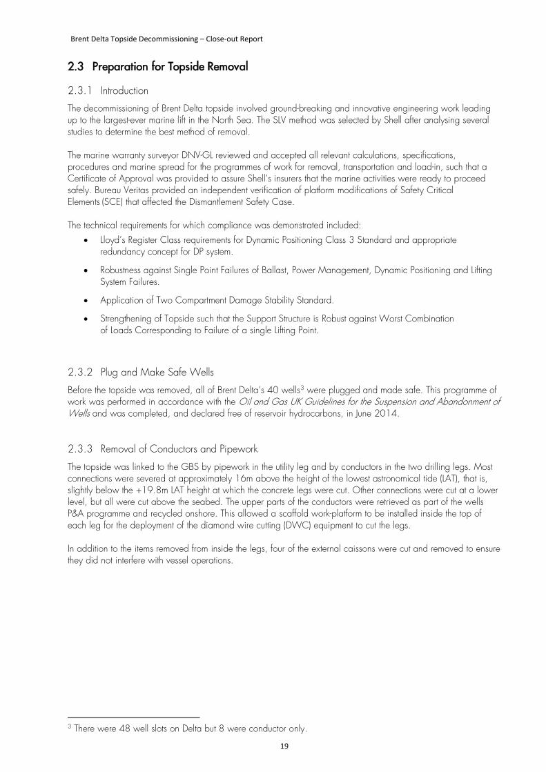
Structural preparations for the removal of the Brent Delta topside started in the summer of 2014. To allow the lifting beams of the SLV to make secure contact with the topside, and to ensure that the topside was strong enough to be lifted in this way, eight specifically- designed steel lift points (“cruciforms”), weighing between 15 tonnes and 20 tonnes each, were welded into place on the underside of the deck in the summer of 2015 (Figure 9). This was an extremely complicated programme of work which required a large amount of scaffold access and the installation of underdeck runway beams to allow the lift points to be installed. The installation of the underdeck runway beams required the removal of some of the underdeck fixtures and fittings. After the lift points had been installed, sections of the runway beams were removed, and laser surveys were performed to provide Allseas with the exact positions of the lift points. Figure 9. A Cruciform Strengthening beam in Place under the PGDS on Brent Delta.
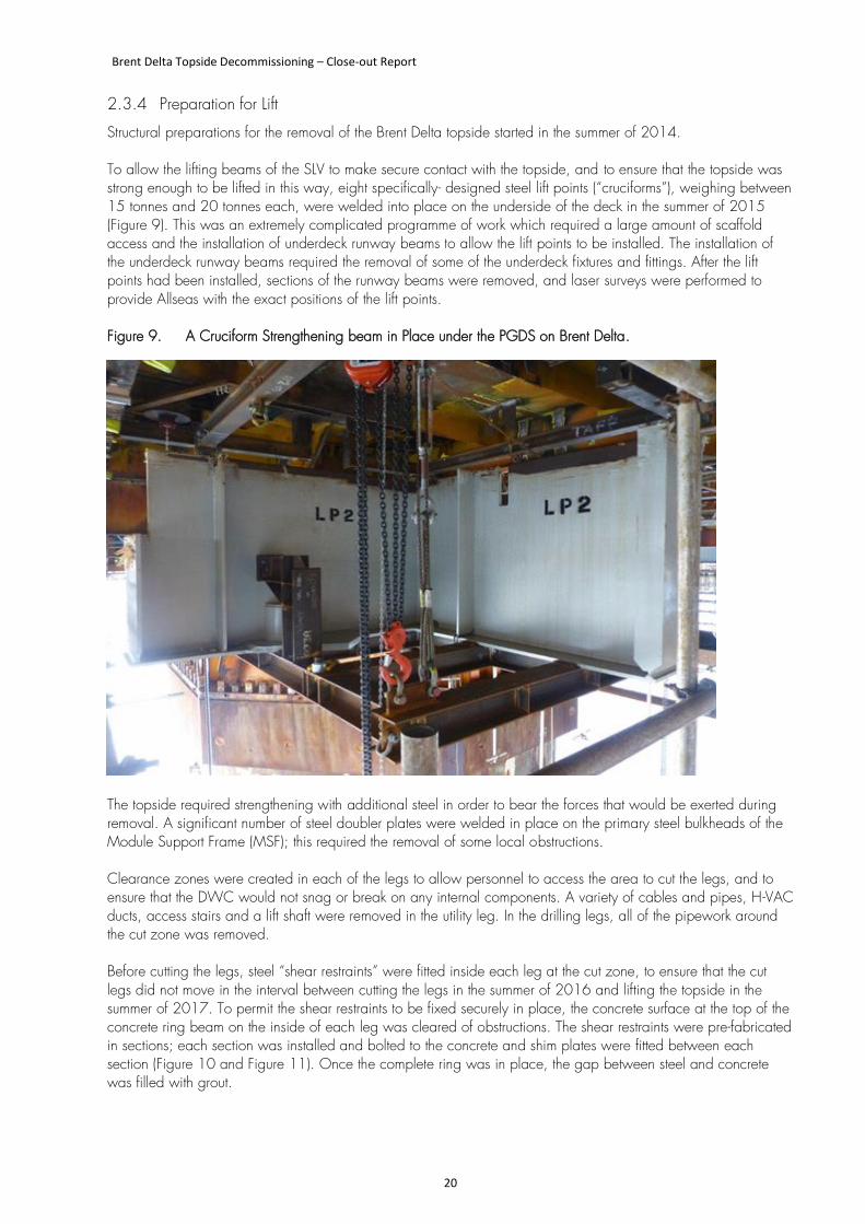
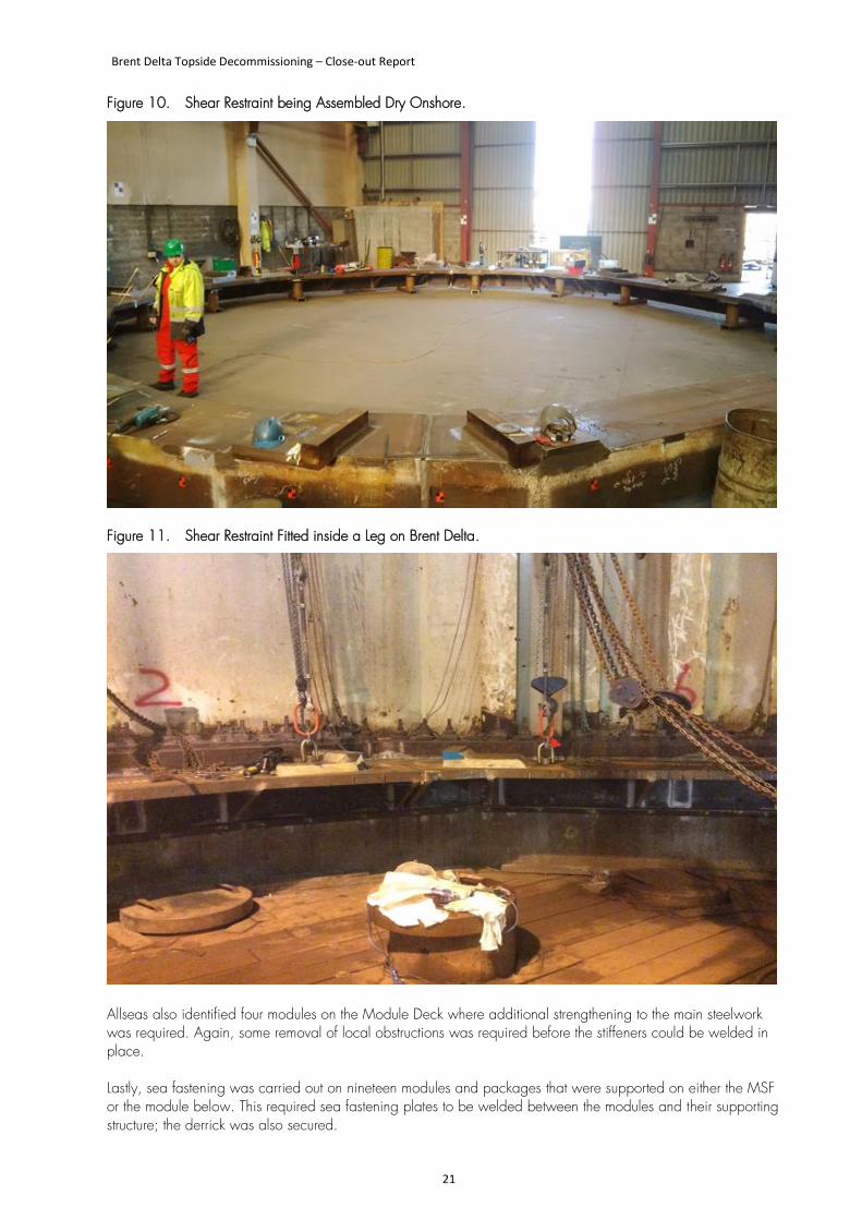
The topside required strengthening with additional steel in order to bear the forces that would be exerted during removal. A significant number of steel doubler plates were welded in place on the primary steel bulkheads of the Module Support Frame (MSF); this required the removal of some local obstructions. Clearance zones were created in each of the legs to allow personnel to access the area to cut the legs, and to ensure that the DWC would not snag or break on any internal components. A variety of cables and pipes, H-VAC ducts, access stairs and a lift shaft were removed in the utility leg. In the drilling legs, all of the pipework around the cut zone was removed. Before cutting the legs, steel “shear restraints” were fitted inside each leg at the cut zone, to ensure that the cut legs did not move in the interval between cutting the legs in the summer of 2016 and lifting the topside in the summer of 2017. To permit the shear restraints to be fixed securely in place, the concrete surface at the top of the concrete ring beam on the inside of each leg was cleared of obstructions. The shear restraints were pre-fabricated in sections; each section was installed and bolted to the concrete and shim plates were fitted between each section (Figure 10 and Figure 11). Once the complete ring was in place, the gap between steel and concrete was filled with grout.
Brent Delta Topside Decommissioning – Close-out Report
21
Figure 10. Shear Restraint being Assembled Dry Onshore.
Figure 11. Shear Restraint Fitted inside a Leg on Brent Delta.
Allseas also identified four modules on the Module Deck where additional strengthening to the main steelwork was required. Again, some removal of local obstructions was required before the stiffeners could be welded in place. Lastly, sea fastening was carried out on nineteen modules and packages that were supported on either the MSF or the module below. This required sea fastening plates to be welded between the modules and their supporting structure; the derrick was also secured.
Brent Delta Topside Decommissioning – Close-out Report
22
The design reports for the under-deck strengthening and the Dismantlement Safety Case were accepted by the UK Health and Safety Executive (UK HSE) in 2016, well in advance of the 2017 lift. The whole structure was checked for loose or damaged items and components, and these were either repaired or removed.
2.3.5 Cleaning of Topside Process facilities before Removal
Before the topside was removed, the topside process systems were drained, purged, and vented (and in some cases also flushed), as appropriate, to ensure no pockets of hydrocarbon liquid or gas were present. Additional vents were created at selected locations in the topside process system to ensure that they were not recharged from any trapped inventories, and drained systems were left open to the atmosphere to allow free-venting to occur so that gases did not build up. It was known that residual material may have accumulated in ‘dead legs’ (such as the bends of pipes) but large quantities were not expected to be present; by virtue of their location such residual materials were not likely to escape during lifting or transportation. Due to the possibility of needing to re-man the topside briefly before the lift, a small volume of diesel was left on the platform; the tonnage and location were included in the final inventory in the Brent Materials Inventory Technical Note. Any potential leak sources that were created in the preparation for the removal of the topside were managed through each individual work-pack associated with each project scope. Shell provided Able with an overview of the tanks and vessels that had been cleaned, and it was made clear that all other tanks and vessels should be sampled before dismantlement. The majority of lubricating (‘lube’) oils were removed and shipped to shore for disposal before the removal of the topside. During the topside preparation scopes, all drains within the modules were flushed, plugged and capped. Drains outside the modules were retro-jetted and left open to sea to stop rain water gathering. Brent Delta had two drain tanks; one was cleaned and dismantled, and the other was emptied and left isolated. Any liquids present on the topside were collected in drip trays and bunds. The remaining chemicals were containerised, and oils were transferred to tote tanks (transportable containers) before being shipped to shore for disposal (except for the chemicals/oils required for maintaining the equipment for a possible re-manning, which were secured in a bunded container). Following CoP in December 2011, fifteen of the sixteen oil storage cells in the GBS had been emptied of bulk oil and therefore contained attic oil and interphase material, water and cell sediment. The remaining oil storage cell contained approximately 5,000m3 of produced oil and emulsion. Any oil derived from topside cleaning was routed into this cell for temporary storage. On completion of the topside cleaning operations a final oil export run was undertaken in July 2015, to ensure that as much oil and emulsion as possible was removed from this cell before the topside was lifted.
2.3.6 Cutting the Legs
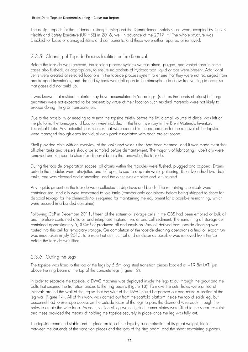
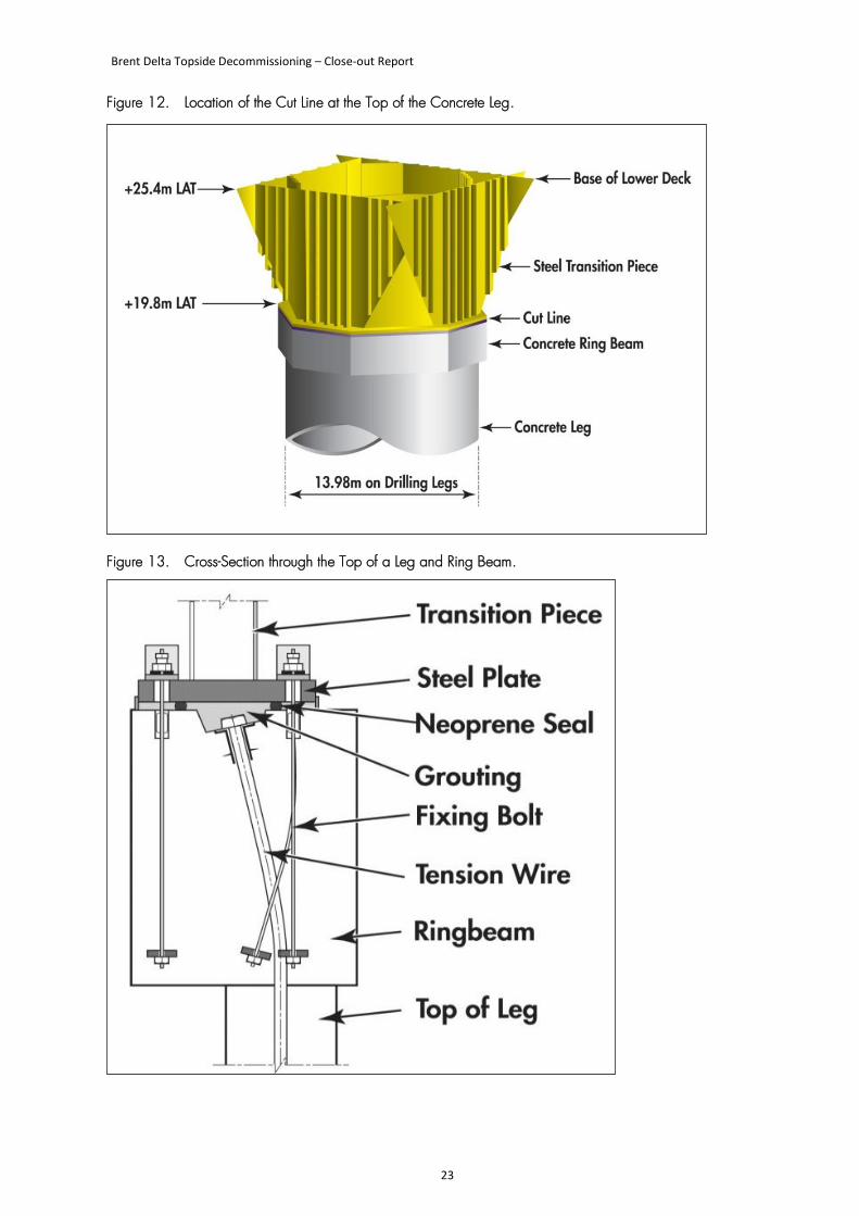
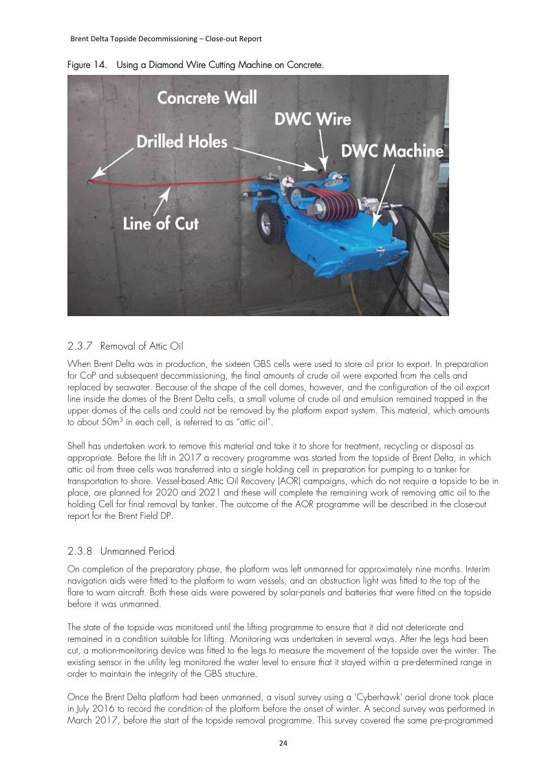
The topside was fixed to the top of the legs by 5.5m long steel transition pieces located at +19.8m LAT, just above the ring beam at the top of the concrete legs (Figure 12). In order to separate the topside, a DWC machine was deployed inside the legs to cut through the grout and the bolts that secured the transition pieces to the ring beams (Figure 13). To make the cuts, holes were drilled at intervals around the wall of the leg so that the wire of the DWC could be passed out and round a section of the leg wall (Figure 14). All of this work was carried out from the scaffold platform inside the top of each leg, but personnel had to use rope access on the outside faces of the legs to pass the diamond wire back through the holes to create the wire loop. As each section of leg was cut, steel corner plates were fitted to the shear restraints and these provided the means of holding the topside securely in place once the leg was fully cut. The topside remained stable and in place on top of the legs by a combination of its great weight, friction between the cut ends of the transition pieces and the tops of the ring beam, and the shear restraining supports.
Brent Delta Topside Decommissioning – Close-out Report
23
Figure 12. Location of the Cut Line at the Top of the Concrete Leg.
Figure 13. Cross-Section through the Top of a Leg and Ring Beam.
Brent Delta Topside Decommissioning – Close-out Report
24
Figure 14. Using a Diamond Wire Cutting Machine on Concrete.
2.3.7 Removal of Attic Oil
When Brent Delta was in production, the sixteen GBS cells were used to store oil prior to export. In preparation for CoP and subsequent decommissioning, the final amounts of crude oil were exported from the cells and replaced by seawater. Because of the shape of the cell domes, however, and the configuration of the oil export line inside the domes of the Brent Delta cells, a small volume of crude oil and emulsion remained trapped in the upper domes of the cells and could not be removed by the platform export system. This material, which amounts to about 50m3 in each cell, is referred to as “attic oil”. Shell has undertaken work to remove this material and take it to shore for treatment, recycling or disposal as appropriate. Before the lift in 2017 a recovery programme was started from the topside of Brent Delta, in which attic oil from three cells was transferred into a single holding cell in preparation for pumping to a tanker for transportation to shore. Vessel-based Attic Oil Recovery (AOR) campaigns, which do not require a topside to be in place, are planned for 2020 and 2021 and these will complete the remaining work of removing attic oil to the holding Cell for final removal by tanker. The outcome of the AOR programme will be described in the close-out report for the Brent Field DP.
2.3.8 Unmanned Period
On completion of the preparatory phase, the platform was left unmanned for approximately nine months. Interim navigation aids were fitted to the platform to warn vessels, and an obstruction light was fitted to the top of the flare to warn aircraft. Both these aids were powered by solar-panels and batteries that were fitted on the topside before it was unmanned. The state of the topside was monitored until the lifting programme to ensure that it did not deteriorate and remained in a condition suitable for lifting. Monitoring was undertaken in several ways. After the legs had been cut, a motion-monitoring device was fitted to the legs to measure the movement of the topside over the winter. The existing sensor in the utility leg monitored the water level to ensure that it stayed within a pre-determined range in order to maintain the integrity of the GBS structure. Once the Brent Delta platform had been unmanned, a visual survey using a 'Cyberhawk' aerial drone took place in July 2016 to record the condition of the platform before the onset of winter. A second survey was performed in March 2017, before the start of the topside removal programme. This survey covered the same pre-programmed
Brent Delta Topside Decommissioning – Close-out Report
25
flight path as the first survey and confirmed no deterioration, damage or presence of loose components or equipment.
2.4 Removal and Load-In of Topside
2.4.1 Lifting the Topside
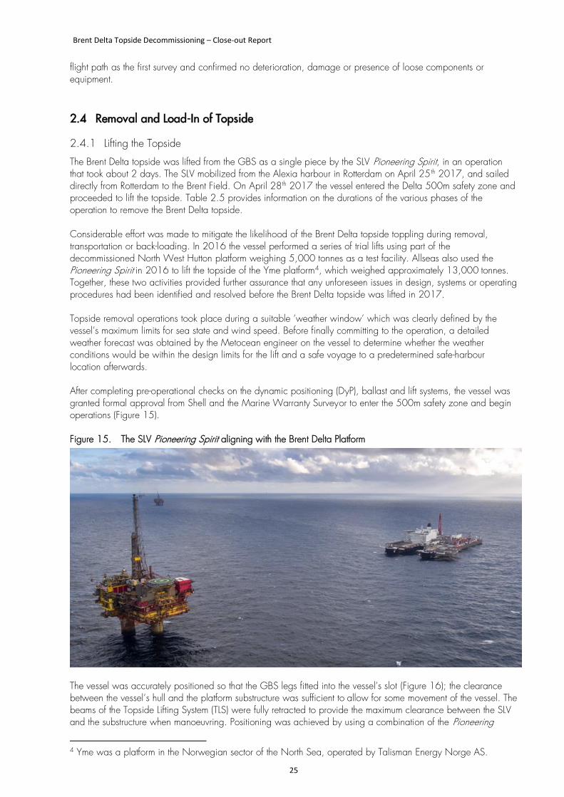
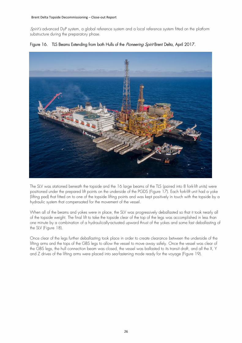
The Brent Delta topside was lifted from the GBS as a single piece by the SLV Pioneering Spirit, in an operation that took about 2 days. The SLV mobilized from the Alexia harbour in Rotterdam on April 25 th 2017, and sailed directly from Rotterdam to the Brent Field. On April 28th 2017 the vessel entered the Delta 500m safety zone and proceeded to lift the topside. Table 2.5 provides information on the durations of the various phases of the operation to remove the Brent Delta topside. Considerable effort was made to mitigate the likelihood of the Brent Delta topside toppling during removal, transportation or back-loading. In 2016 the vessel performed a series of trial lifts using part of the decommissioned North West Hutton platform weighing 5,000 tonnes as a test facility. Allseas also used the Pioneering Spirit in 2016 to lift the topside of the Yme platform4, which weighed approximately 13,000 tonnes. Together, these two activities provided further assurance that any unforeseen issues in design, systems or operating procedures had been identified and resolved before the Brent Delta topside was lifted in 2017. Topside removal operations took place during a suitable ‘weather window’ which was clearly defined by the vessel’s maximum limits for sea state and wind speed. Before finally committing to the operation, a detailed weather forecast was obtained by the Metocean engineer on the vessel to determine whether the weather conditions would be within the design limits for the lift and a safe voyage to a predetermined safe-harbour location afterwards. After completing pre-operational checks on the dynamic positioning (DyP), ballast and lift systems, the vessel was granted formal approval from Shell and the Marine Warranty Surveyor to enter the 500m safety zone and begin operations (Figure 15). Figure 15. The SLV Pioneering Spirit aligning with the Brent Delta Platform
The vessel was accurately positioned so that the GBS legs fitted into the vessel’s slot (Figure 16); the clearance between the vessel’s hull and the platform substructure was sufficient to allow for some movement of the vessel. The beams of the Topside Lifting System (TLS) were fully retracted to provide the maximum clearance between the SLV and the substructure when manoeuvring. Positioning was achieved by using a combination of the Pioneering
4 Yme was a platform in the Norwegian sector of the North Sea, operated by Talisman Energy Norge AS.
Brent Delta Topside Decommissioning – Close-out Report
26
Spirit’s advanced DyP system, a global reference system and a local reference system fitted on the platform substructure during the preparatory phase. Figure 16. TLS Beams Extending from both Hulls of the Pioneering Spirit Brent Delta, April 2017.
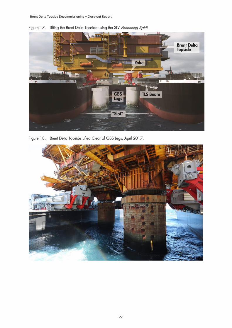
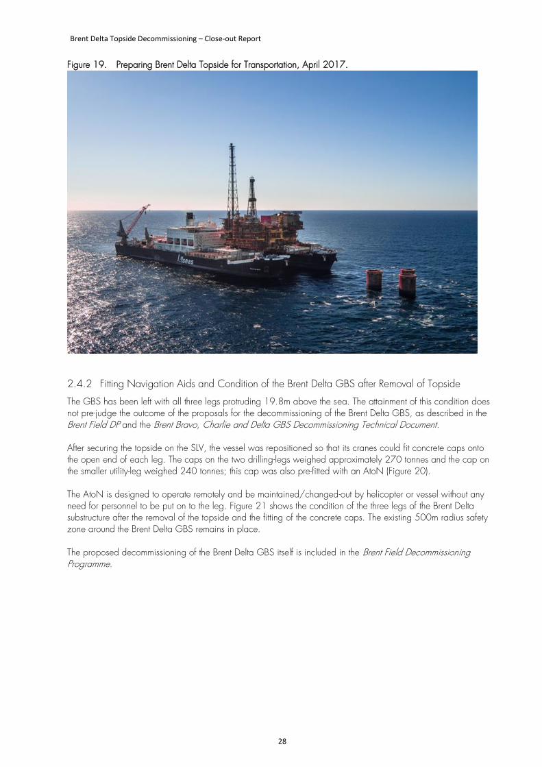
The SLV was stationed beneath the topside and the 16 large beams of the TLS (paired into 8 fork-lift units) were positioned under the prepared lift points on the underside of the PGDS (Figure 17). Each fork-lift unit had a yoke (lifting pad) that fitted on to one of the topside lifting points and was kept positively in touch with the topside by a hydraulic system that compensated for the movement of the vessel. When all of the beams and yokes were in place, the SLV was progressively deballasted so that it took nearly all of the topside weight. The final lift to take the topside clear of the top of the legs was accomplished in less than one minute by a combination of a hydraulically-actuated upward thrust of the yokes and some fast deballasting of the SLV (Figure 18). Once clear of the legs further deballasting took place in order to create clearance between the underside of the lifting arms and the tops of the GBS legs to allow the vessel to move away safely. Once the vessel was clear of the GBS legs, the hull connection beam was closed, the vessel was ballasted to its transit draft, and all the X, Y and Z drives of the lifting arms were placed into sea-fastening mode ready for the voyage (Figure 19).
Brent Delta Topside Decommissioning – Close-out Report
27
Figure 17. Lifting the Brent Delta Topside using the SLV Pioneering Spirit.
Figure 18. Brent Delta Topside Lifted Clear of GBS Legs, April 2017.
Brent Delta Topside Decommissioning – Close-out Report
28
Figure 19. Preparing Brent Delta Topside for Transportation, April 2017.
2.4.2 Fitting Navigation Aids and Condition of the Brent Delta GBS after Removal of Topside
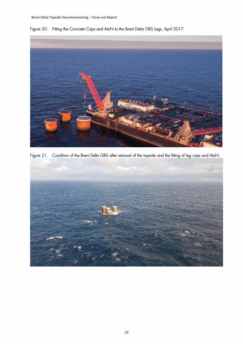
The GBS has been left with all three legs protruding 19.8m above the sea. The attainment of this condition does not pre-judge the outcome of the proposals for the decommissioning of the Brent Delta GBS, as described in the Brent Field DP and the Brent Bravo, Charlie and Delta GBS Decommissioning Technical Document. After securing the topside on the SLV, the vessel was repositioned so that its cranes could fit concrete caps onto the open end of each leg. The caps on the two drilling-legs weighed approximately 270 tonnes and the cap on the smaller utility-leg weighed 240 tonnes; this cap was also pre-fitted with an AtoN (Figure 20). The AtoN is designed to operate remotely and be maintained/changed-out by helicopter or vessel without any need for personnel to be put on to the leg. Figure 21 shows the condition of the three legs of the Brent Delta substructure after the removal of the topside and the fitting of the concrete caps. The existing 500m radius safety zone around the Brent Delta GBS remains in place. The proposed decommissioning of the Brent Delta GBS itself is included in the Brent Field Decommissioning Programme.
Brent Delta Topside Decommissioning – Close-out Report
29
Figure 20. Fitting the Concrete Caps and AtoN to the Brent Delta GBS Legs, April 2017.
Figure 21. Condition of the Brent Delta GBS after removal of the topside and the fitting of leg caps and AtoN.
Brent Delta Topside Decommissioning – Close-out Report
30
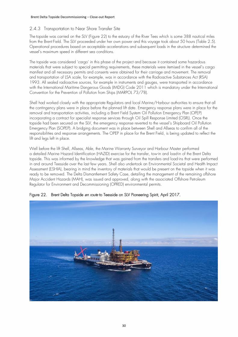
2.4.3 Transportation to Near Shore Transfer Site
The topside was carried on the SLV (Figure 22) to the estuary of the River Tees which is some 388 nautical miles from the Brent Field. The SLV proceeded under her own power and this voyage took about 50 hours (Table 2.5). Operational procedures based on acceptable accelerations and subsequent loads in the structure determined the vessel’s maximum speed in different sea conditions. The topside was considered ‘cargo’ in this phase of the project and because it contained some hazardous materials that were subject to special permitting requirements, these materials were itemised in the vessel’s cargo manifest and all necessary permits and consents were obtained for their carriage and movement. The removal and transportation of LSA scale, for example, was in accordance with the Radioactive Substances Act (RSA) 1993. All sealed radioactive sources, for example in instruments and gauges, were transported in accordance with the International Maritime Dangerous Goods (IMDG) Code 2011 which is mandatory under the International Convention for the Prevention of Pollution from Ships (MARPOL 73/78). Shell had worked closely with the appropriate Regulators and local Marine/Harbour authorities to ensure that all the contingency plans were in place before the planned lift date. Emergency response plans were in place for the removal and transportation activities, including a Brent Field System Oil Pollution Emergency Plan (OPEP) incorporating a contract for specialist response services through Oil Spill Response Limited (OSRL). Once the topside had been secured on the SLV, the emergency response reverted to the vessel’s Shipboard Oil Pollution Emergency Plan (SOPEP). A bridging document was in place between Shell and Allseas to confirm all of the responsibilities and response arrangements. The OPEP in place for the Brent Field, is being updated to reflect the lift and legs left in place. Well before the lift Shell, Allseas, Able, the Marine Warranty Surveyor and Harbour Master performed a detailed Marine Hazard Identification (HAZID) exercise for the transfer, tow-in and load-in of the Brent Delta topside. This was informed by the knowledge that was gained from the transfers and load-ins that were performed in and around Teesside over the last few years. Shell also undertook an Environmental Societal and Health Impact Assessment (ESHIA), bearing in mind the inventory of materials that would be present on the topside when it was ready to be removed. The Delta Dismantlement Safety Case, detailing the management of the remaining offshore Major Accident Hazards (MAH), was issued and approved, along with the associated Offshore Petroleum Regulator for Environment and Decommissioning (OPRED) environmental permits. Figure 22. Brent Delta Topside en route to Teesside on SLV Pioneering Spirit, April 2017.
Brent Delta Topside Decommissioning – Close-out Report
31
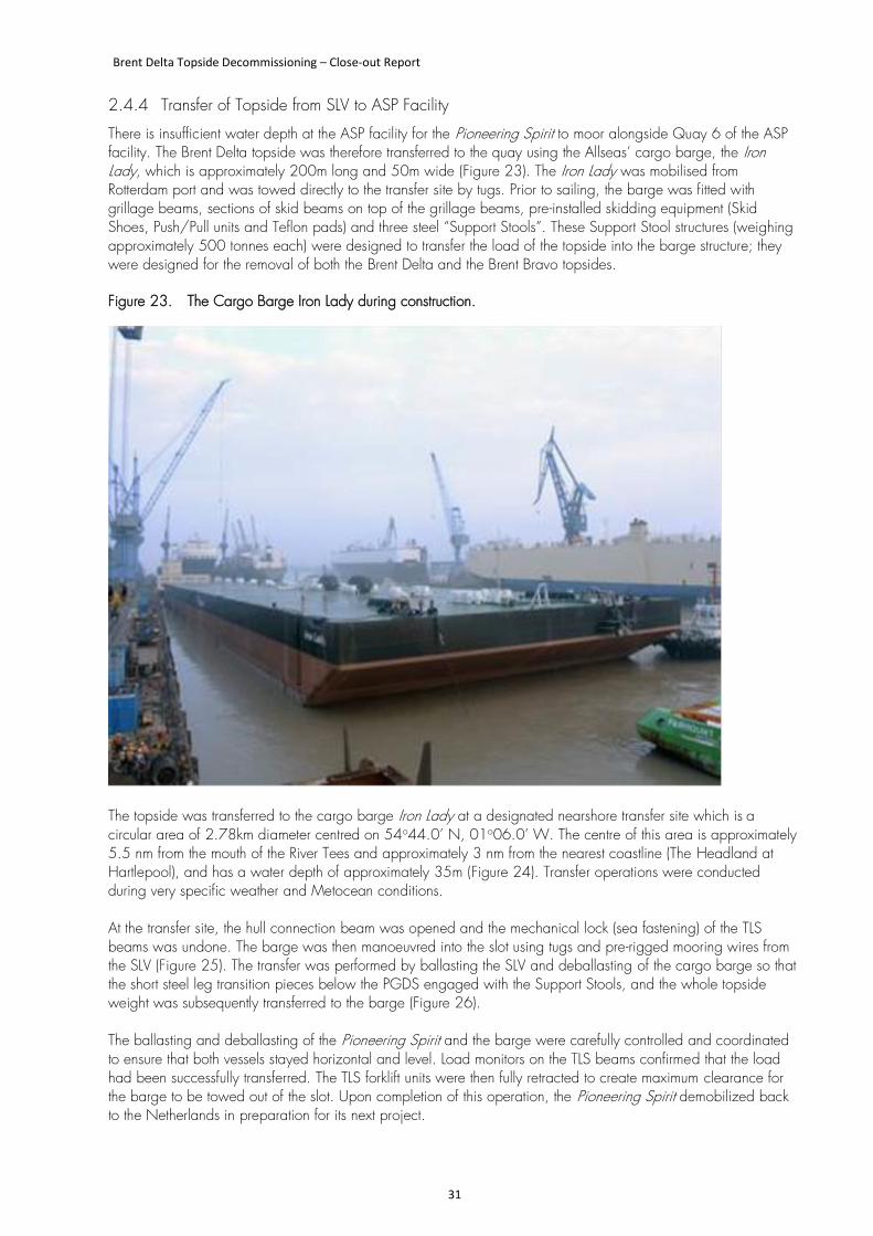
2.4.4 Transfer of Topside from SLV to ASP Facility
There is insufficient water depth at the ASP facility for the Pioneering Spirit to moor alongside Quay 6 of the ASP facility. The Brent Delta topside was therefore transferred to the quay using the Allseas’ cargo barge, the Iron Lady, which is approximately 200m long and 50m wide (Figure 23). The Iron Lady was mobilised from Rotterdam port and was towed directly to the transfer site by tugs. Prior to sailing, the barge was fitted with grillage beams, sections of skid beams on top of the grillage beams, pre-installed skidding equipment (Skid Shoes, Push/Pull units and Teflon pads) and three steel “Support Stools”. These Support Stool structures (weighing approximately 500 tonnes each) were designed to transfer the load of the topside into the barge structure; they were designed for the removal of both the Brent Delta and the Brent Bravo topsides. Figure 23. The Cargo Barge Iron Lady during construction.
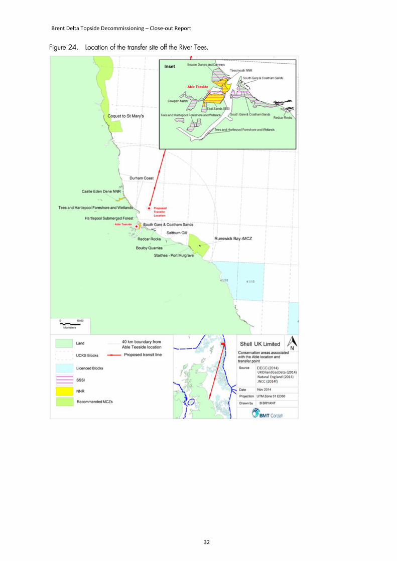
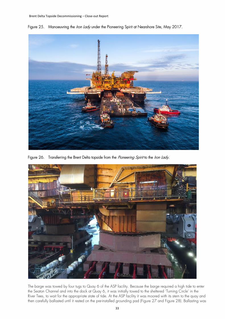
The topside was transferred to the cargo barge Iron Lady at a designated nearshore transfer site which is a circular area of 2.78km diameter centred on 54o44.0’ N, 01o06.0’ W. The centre of this area is approximately 5.5 nm from the mouth of the River Tees and approximately 3 nm from the nearest coastline (The Headland at Hartlepool), and has a water depth of approximately 35m (Figure 24). Transfer operations were conducted during very specific weather and Metocean conditions. At the transfer site, the hull connection beam was opened and the mechanical lock (sea fastening) of the TLS beams was undone. The barge was then manoeuvred into the slot using tugs and pre-rigged mooring wires from the SLV (Figure 25). The transfer was performed by ballasting the SLV and deballasting of the cargo barge so that the short steel leg transition pieces below the PGDS engaged with the Support Stools, and the whole topside weight was subsequently transferred to the barge (Figure 26). The ballasting and deballasting of the Pioneering Spirit and the barge were carefully controlled and coordinated to ensure that both vessels stayed horizontal and level. Load monitors on the TLS beams confirmed that the load had been successfully transferred. The TLS forklift units were then fully retracted to create maximum clearance for the barge to be towed out of the slot. Upon completion of this operation, the Pioneering Spirit demobilized back to the Netherlands in preparation for its next project.
Brent Delta Topside Decommissioning – Close-out Report
32
Figure 24. Location of the transfer site off the River Tees.
Brent Delta Topside Decommissioning – Close-out Report
33
Figure 25. Manoeuvring the Iron Lady under the Pioneering Spirit at Nearshore Site, May 2017.
Figure 26. Transferring the Brent Delta topside from the Pioneering Spirit to the Iron Lady.
The barge was towed by four tugs to Quay 6 of the ASP facility. Because the barge required a high tide to enter the Seaton Channel and into the dock at Quay 6, it was initially towed to the sheltered ‘Turning Circle’ in the River Tees, to wait for the appropriate state of tide. At the ASP facility it was moored with its stern to the quay and then carefully ballasted until it rested on the pre-installed grounding pad (Figure 27 and Figure 28). Ballasting was
Brent Delta Topside Decommissioning – Close-out Report
34
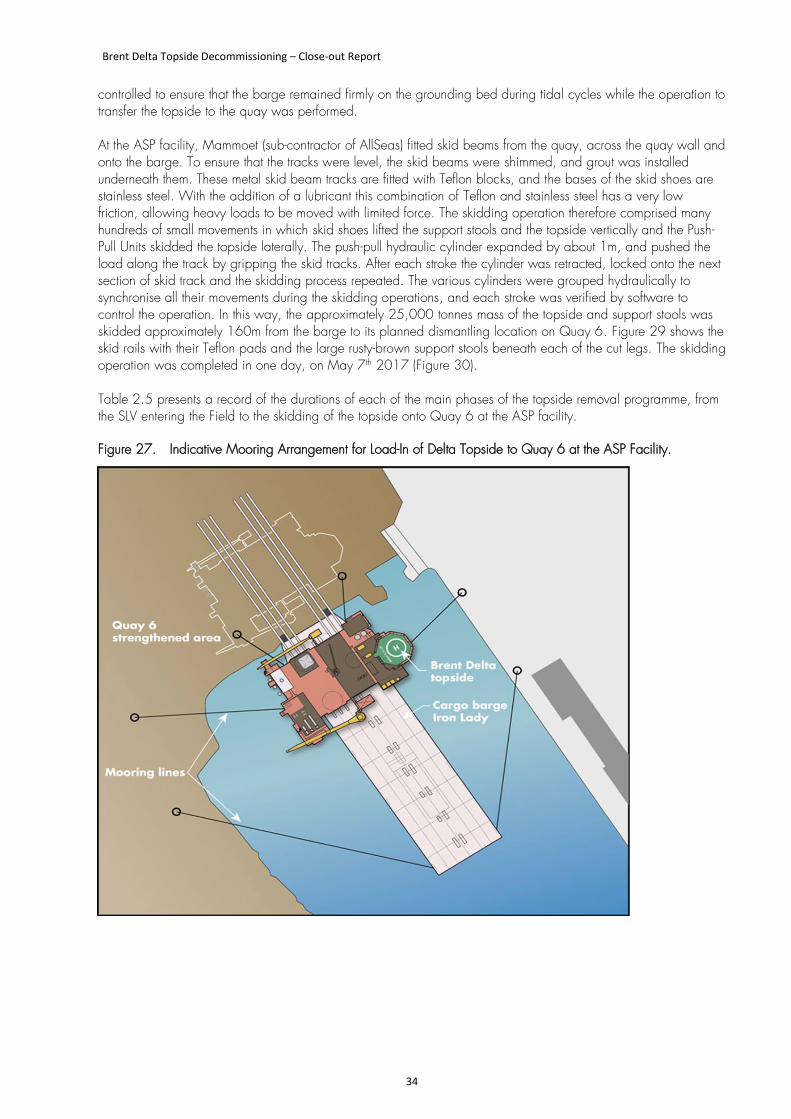
controlled to ensure that the barge remained firmly on the grounding bed during tidal cycles while the operation to transfer the topside to the quay was performed. At the ASP facility, Mammoet (sub-contractor of AllSeas) fitted skid beams from the quay, across the quay wall and onto the barge. To ensure that the tracks were level, the skid beams were shimmed, and grout was installed underneath them. These metal skid beam tracks are fitted with Teflon blocks, and the bases of the skid shoes are stainless steel. With the addition of a lubricant this combination of Teflon and stainless steel has a very low friction, allowing heavy loads to be moved with limited force. The skidding operation therefore comprised many hundreds of small movements in which skid shoes lifted the support stools and the topside vertically and the Push-Pull Units skidded the topside laterally. The push-pull hydraulic cylinder expanded by about 1m, and pushed the load along the track by gripping the skid tracks. After each stroke the cylinder was retracted, locked onto the next section of skid track and the skidding process repeated. The various cylinders were grouped hydraulically to synchronise all their movements during the skidding operations, and each stroke was verified by software to control the operation. In this way, the approximately 25,000 tonnes mass of the topside and support stools was skidded approximately 160m from the barge to its planned dismantling location on Quay 6. Figure 29 shows the skid rails with their Teflon pads and the large rusty-brown support stools beneath each of the cut legs. The skidding operation was completed in one day, on May 7th 2017 (Figure 30). Table 2.5 presents a record of the durations of each of the main phases of the topside removal programme, from the SLV entering the Field to the skidding of the topside onto Quay 6 at the ASP facility. Figure 27. Indicative Mooring Arrangement for Load-In of Delta Topside to Quay 6 at the ASP Facility.
Brent Delta Topside Decommissioning – Close-out Report
35
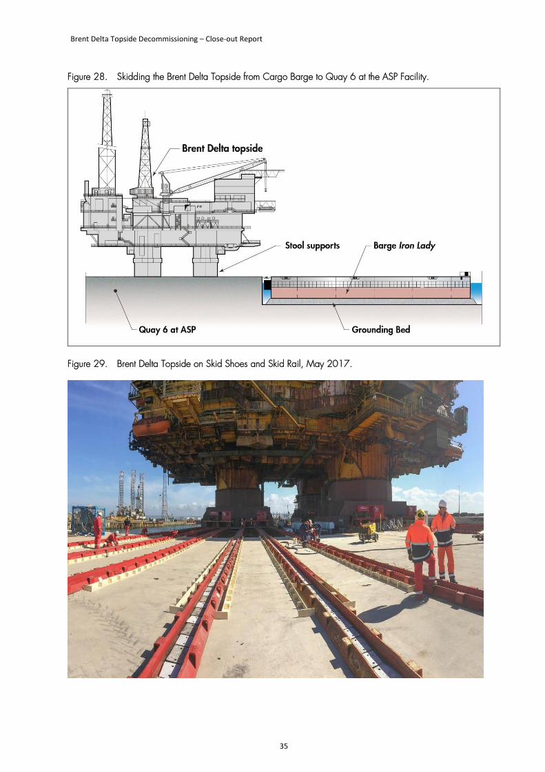
Figure 28. Skidding the Brent Delta Topside from Cargo Barge to Quay 6 at the ASP Facility.
Figure 29. Brent Delta Topside on Skid Shoes and Skid Rail, May 2017.
Brent Delta Topside Decommissioning – Close-out Report
36
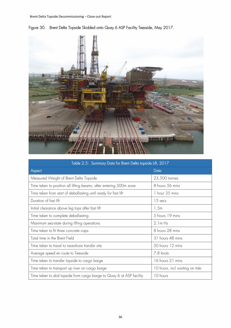
Figure 30. Brent Delta Topside Skidded onto Quay 6 ASP Facility Teesside, May 2017.
Table 2.5: Summary Data for Brent Delta topside Lift, 2017
Aspect Data
Measured Weight of Brent Delta Topside 23,500 tonnes
Time taken to position all lifting beams, after entering 500m zone 8 hours 56 mins
Time taken from start of deballasting until ready for fast lift 1 hour 35 mins
Duration of fast lift 15 secs
Initial clearance above leg tops after fast lift 1.5m
Time taken to complete deballasting 5 hours 19 mins
Maximum sea-state during lifting operations 2.1m Hs
Time taken to fit three concrete caps 8 hours 28 mins
Total time in the Brent Field 31 hours 48 mins
Time taken to travel to nearshore transfer site 50 hours 12 mins
Average speed en route to Teesside 7.8 knots
Time taken to transfer topside to cargo barge 16 hours 21 mins
Time taken to transport up river on cargo barge 10 hours, incl waiting on tide
Time taken to skid topside from cargo barge to Quay 6 at ASP facility 10 hours
Brent Delta Topside Decommissioning – Close-out Report
37
2.5 Dismantling and Recycling
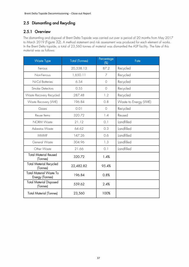
2.5.1 Overview The dismantling and disposal of Brent Delta Topside was carried out over a period of 20 months from May 2017 to March 2019 (Figure 32). A method statement and risk assessment was produced for each element of works. In the Brent Delta topside, a total of 23,560 tonnes of material was dismantled the ASP facility. The fate of this material was as follows:
Waste Type Total (Tonnes) Percentage
(%) Fate
Ferrous 20,538.13 87.2 Recycled
Non-Ferrous 1,650.11 7 Recycled
Ni-Cd Batteries 6.54 0 Recycled
Smoke Detectors 0.55 0 Recycled
Waste Recovery Recycled 287.48 1.2 Recycled
Waste Recovery (WtE) 196.84 0.8 Waste to Energy (WtE)
Gases 0.01 0 Recycled
Reuse Items 320.72 1.4 Reused
NORM Waste 21.12 0.1 Landfilled
Asbestos Waste 64.62 0.3 Landfilled
MMMF 147.26 0.6 Landfilled
General Waste 304.96 1.3 Landfilled
Other Waste 21.66 0.1 Landfilled
Total Material Reused (Tonnes)
320.72 1.4%
Total Material Recycled (Tonnes)
22,482.82 95.4%
Total Material Waste To Energy (Tonnes)
196.84 0.8%
Total Material Disposed (Tonnes)
559.62 2.4%
Total Material (Tonnes) 23,560 100%
Brent Delta Topside Decommissioning – Close-out Report
38
2.5.2 Surveys and preliminary work
The initial phase of the project comprised three surveys, namely (i) an initial access survey, (ii) a full visual survey and (iii) a dimensional survey. Once these surveys had been completed, a safe access to the topside was created and a programme of “soft stripping” undertaken. This involved the removal of a wide range of relatively small and easily removed items such as non-perishable foodstuff, furniture, some fittings, domestic and recreational equipment and items, tools and small pieces of equipment. Where possible, these were distributed to local charities and emergency services including Stockton Fire Service and Hartlepool Food Bank. A number of items were also removed and transported to Aberdeen for re-use by Shell. Items included:
• Air compressors • Emergency generator • Leg Levelling & Monitoring equipment • Fire pump module • Pigging valves • PPE • Fire Pump Control Panel
Non-ferrous items were also identified and removed at this time, so that they could be recycled under separate waste streams. Before starting to dismantle the main structure, a fully intrusive survey was undertaken to locate all Asbestos Containing Material (ACM), in accordance with the requirements of HSE Guidance document HSG264. The removal of ACM commenced in September 2017 and continued throughout the demolition work. In total, 65 tonnes of ACM was removed from the topside. The initial under-estimate of ACM had a significant adverse impact on the original demolition schedule. A further pre-demolition survey was also undertaken by a specialist contractor to screen for the presence of LSA scale and NORM sludge; Shell had estimated that there would be 69 tonnes of LSA scale and 30 tonnes of sludge (e.g. in separators, vessels, and hydro-cyclones). The survey involved the screening of the external surfaces of all accessible pipework and vessels, paying particular attention to those areas where contamination would be most likely to be present (e.g. separators and ancillary pipework). The survey also included contamination monitoring in areas where breaks in containment could have occurred, equipment was likely to have been internally contaminated and marked up areas indicating the presence (or previous presence) of NORM or radioactive materials. Refrigerant gases were also present in various cooling machines and these were removed by a specialist contractor for re-use.
2.5.3 Dismantling the main structure
The Brent Delta was equipped with two pedestal cranes, one each on the East and West faces. Both cranes were shut down and secured in the rest position offshore, before the module was transported to ASP. At the start of the work, the east crane was re-commissioned for Able by Durham Lifting Company in order to assist in the removal of parts of the structure as it was being demolished. The west crane was not re-commissioned, and its crane jib was removed early in the work. The demolition of the main structure of the topside followed a sequential ‘top-down’ approach, and was principally progressed by weakening parts of the structure and allowing them to drop onto the ground. Where parts of the structure cantilevered from the main body of the topside, this could be achieved by selective cutting until the part simply detached itself under gravity. In other cases, ropes were attached to the weakened structure in order to pull it clear. Prior to such operations, thick layers of sand were placed around the base of the topside, to absorb the force of the falling items and protect the surface of the quay of the remaining part. On the ground, separated parts of the structure were processed for scrap by cutting them into steel “coupons” measuring no more than 5ft x 2ft x 2ft. This material will ultimately be sold to the steel-making industry for recycling and re-use.
Brent Delta Topside Decommissioning – Close-out Report
39
2.6 Post-Topside Removal Activities Offshore
2.6.1 Information to Third-party Users of the Area
After the removal of the topside, the GBS was entered into the FishSAFE programme of electronic warning, the UK Hydrographic Office (UKHO) and the Maritime Coastguard Agency (MCA) were notified, and a Notice to Mariners was issued so that other users of the sea could amend their charts. The AtoN that has been fitted was approved by the UKHO and the UK Coastguard.
2.6.2 Monitoring and Maintenance
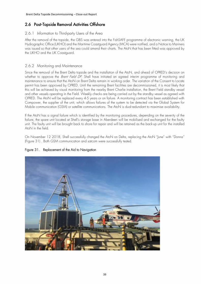
Since the removal of the Brent Delta topside and the installation of the AtoN, and ahead of OPRED’s decision on whether to approve the Brent Field DP, Shell have initiated an agreed interim programme of monitoring and maintenance to ensure that the AtoN on Brent Delta remain in working order. The variation of the Consent to Locate permit has been approved by OPRED. Until the remaining Brent facilities are decommissioned, it is most likely that this will be achieved by visual monitoring from the nearby Brent Charlie installation, the Brent Field standby vessel and other vessels operating in the Field. Weekly checks are being carried out by the standby vessel as agreed with OPRED. The AtoN will be replaced every 4-5 years or on failure. A monitoring contract has been established with Compower, the supplier of the unit, which allows failures of the system to be detected via the Global System for Mobile communication (GSM) or satellite communications. The AtoN is dual-redundant to maximise availability. If the AtoN has a signal failure which is identified by the monitoring procedures, depending on the severity of the failure, the spare unit located at Shell’s storage base in Aberdeen will be mobilised and exchanged for the faulty unit. The faulty unit will be brought back to shore for repair and will be retained as the back-up unit for the installed AtoN in the field. On November 12 2018, Shell successfully changed the AtoN on Delta, replacing the AtoN “June” with “Donna” (Figure 31) . Both GSM communication and satcom were successfully tested. Figure 31. Replacement of the Aid to Navigation
Brent Delta Topside Decommissioning – Close-out Report
40
2.6.3 Post-Topside Removal Debris Clearance and Verification
The programme to remove the Brent Delta topside by SLV did not result in the deposition of any debris on the seabed at Brent Delta. The existing debris on the top of the Brent Delta GBS cells and on the seabed around the GBS will be removed in one or more ‘campaigns’ which will be performed across the whole Brent Field once all the platforms and pipelines have been decommissioned.
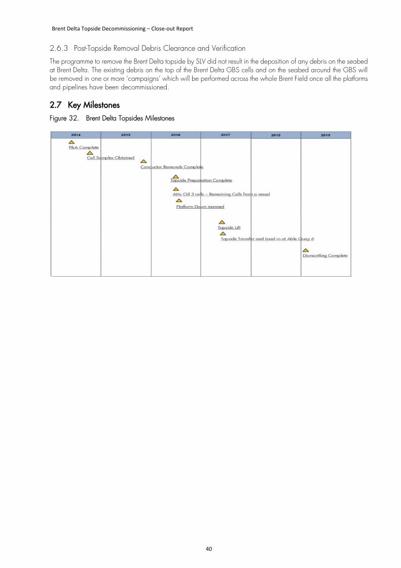
2.7 Key Milestones Figure 32. Brent Delta Topsides Milestones
Brent Delta Topside Decommissioning – Close-out Report
41
This page is left intentionally blank
Brent Delta Topside Decommissioning – Close-out Report
42
3 IMPACT ON ENVIRONMENT
3.1 Comparison with assumptions in the Environmental Impact Assessment In accordance with the DECC Guidance Notes for Decommissioning of Offshore Oil and Gas Installations under the Petroleum Act 1998 (as amended by the Energy Act 2008), an Environmental Impact Assessment (EIA) was carried out to support the Shell’s Brent Field Decommissioning Programmes5. The findings of the EIA were reported in the Brent Field Decommissioning Environmental Statement (ES) which presents:
• A description of the Brent Field facilities, and the current environmental condition of the Brent Field, offshore transport route and onshore dismantling location.
• The results of the EIA process to identify and assess both the potential short and long-term impacts of the technically feasible decommissioning options for the Brent Field facilities after industry standard mitigation has been applied.
• The potential environmental impacts of the decommissioning programme of work proposed by Shell.
A separate Impact Assessment (IA) of the near-shore transfer of the Brent Delta topside from the SLV Pioneering Spirit to the barge Iron Lady, subsequent towing to shore (at Seaton Port, Teesside), the load-in to Quay 6, and final subsequent dismantling and disposal operations to be undertaken once there, was carried out by AECOM, and reported in the Brent Removals and Dismantlement Impact Assessment (ESHIA),
The IA was not undertaken to discharge any statutory requirement, in relation to any legislative or regulatory purpose, or to support the gaining of any permission or consent. Rather it was completed to satisfy Shell UK Ltd.’s mandatory requirements under their Health, Safety, Security and Environment (HSSE) and Social Performance (SP) Control Framework. The IA highlighted any areas of potential concern, and aspects where further design was required in order to provide confidence that significant effects would not result. Overall, 29 Actions were created as a result of the IA, and they were all closed out before the dismantling of the Delta topside began. The potential impacts on wintering water birds from the dismantling of marine structures, and associated works such as dredging and piling at Able Seaton Port, were fully addressed in planning application H/2007/0543, and no adverse effects were identified. Nevertheless, Shell commissioned a separate study by INCA6 to investigate whether the dismantling of the Brent Delta at Able Seaton Port caused any disturbance to wintering water birds and seals using Seal Sands. A total of 19 hours was spent monitoring potential disturbance to wintering water birds and 106 hours monitoring potential disturbance to seals. In neither case was any direct incidence of disturbance recorded from activities related to Brent Delta. There were no Environmental Non-compliances reported during the dismantling of the Brent Delta topside.
5 The DECC Guidance Notes Version 6 were in place at the time the EIA was prepared for the Brent Field Decommissioning Programme.
6 INCA are Industry Nature Conservation Association, they have a small specialist team with extensive knowledge of the natural environment of the Tees Valley. The team is drawn from backgrounds in industry, nature conservation and regulation, giving a unique blend of skills and knowledge.
Brent Delta Topside Decommissioning – Close-out Report
43
4 IMPACT ON HEALTH AND SAFETY
4.1 Technical Safety In terms of major accident hazards (MAHs), associated safety critical elements (SCEs) and performance standards (PSs) the transition from an offshore installation in production mode through CoP, dismantlement and eventually post-dismantlement required strategic safety case revisions to ensure that the document reflected changing installation status. Most of the revisions did not require submission to the HSE as they did not constitute a ‘Material Change’, as defined in the offshore safety case regulations. During this transition from production to dismantlement, the significant change in terms of MAHs was the elimination of the gross hydrocarbon inventory, which represents about 50% of the MAH profile on a production installation.
4.2 Occupational Safety The introduction by Shell of the ‘Safety’ project, which focused on a drive towards a fully integrated team approach (onshore/offshore), as well as the introduction of ‘Mindsafety’, helped improve safety performance. Shell’s ‘Safety Project’ took inputs from various sources through surveys as they embarked on their mind safety journey. It included the notion that the right environment to decommission had to be created and that this investment in turn would encourage a positive response from the workforce. By creating the right environment and driving compliance, maintenance programmes and platform integrity, improvements were seen in safety performance, and downtime was improved. This early investment put in place good foundations which were built upon and gave a strong base to meet the challenges which come from the human, engineering, and dynamic aspects of decommissioning, as well as those from the more obvious surroundings themselves. Shell achieved a positive change in safety culture by taking ownership offshore and driving an improved safety performance. This was particularly evident during the last seven months of work on Delta before the platform was unmanned which saw the busiest and most complex period of work completed injury free. In the planning phase prior to CoP, the project decided to move from reverse engineering to single lift, and this also provided an important benefit in reducing risk. The alternative, ‘reverse engineering’, requires significant offshore man-hours to separate the modules so that they can be individually lifted off by HLV. It also involves additional flying and marine risks to support the activity, and thereby exposes personnel to offshore occupational and logistical hazards. Conversely, the single lift methodology largely eliminates the need for module segregation, greatly reduces the overall lifting offshore and considerably simplifies the offshore work scope, which in turn reduces the risk factors described above. In this context the single lift approach was considered to provide an overall risk that was as low as is reasonably practicable (ALARP). Lifting, transportation and offloading were all achieved in 2017 without any occupational safety incidents. The dismantlement was carried out at Able Seaton Port under their Management System and in line with the Construction (Design and Management) Regulations 2015. During the dismantlement there were several first aid and medical treatment cases. There was one serious burn injury to a topman burner during the dismantlement of a crane where the burner cut through a hydraulic line which subsequently ignited. Able implemented a number of corrective actions after investigation of the incident and Shell commissioned a third-party contractor to carry out independent verification of the Shell Client Responsibilities and those of Able for Principal Designer and Principal Contractor.
Brent Delta Topside Decommissioning – Close-out Report
44
4.3 Lesson Learned from Accidents Significant lessons were learnt from the following accidents:
1. A worker hot-cut a hydraulic hose that carried pressurised fluid. Following this event, walk-over surveys of all work areas were instigated in advance of preparing risk assessments to improve hazard identification. PPE standards were changed to improve flame protection.
2. Premature Collapse of Electrical Unit. An electrical unit fell onto a worker who was cutting it free. The worker had not followed the correct cutting sequence and the supervisor had not been present. Following this incident, it was decided that work should not be undertaken unless a supervisor was present.
5 LESSONS LEARNED
5.1 In Planning and Preparation for Decommissioning In advance of the removal of the Brent Delta topside by SLV, the owners prepared the installation for CoP, completed a programme to plug and make safe the wells, rendered the topside hydrocarbons-free, and prepared the topside for removal. The Lessons Learned from this multi-faceted programme of work over approximately 10 years are summarised below. Project-wide Planning
• Decommissioning needs to be considered early in the EOFL phase, i.e. before CoP
• Lack of planning is likely to erode overall Asset value; early planning is likely to enhance Asset value
• A focus on Abex may highlight the need for early Asset investment, e.g. cranes, HVAC and power systems
• Transition into the Decommissioning phase is likely to be just as challenging (if not more so) than production
• Start early - CoP is often triggered by an unplanned event – Be Ready!
• Reduces some risk and ~20% maintenance hours but utility reliability is crucial; e.g. of cranes, power, safety systems
• Prioritise decommissioning work appropriately pre-CoP: it’s a major opportunity to get into a project mindset
• Early strategic decisions will have a major impact to overall decommissioning costs
• Hydrocarbon-free is a more significant milestone than CoP; achieving this milestone can lead to a reduction in maintenance costs of up to 50%.
• A new risk profile means different ways of working
• Engage the market in decommissioning solutions: Continually monitor market conditions to optimise: early input from supply chain
• Organisation Design / People / Skills Planning: improve collaboration between Project / Operations / Wells
• Focus on down-manning, a milestone that has a significant effect on cost and offshore exposure to people.
Cost-savings
• Typically, over 40% of the decommissioning costs on manned installations are associated with the P&A of platform wells.
• Recognise the hierarchy of value drivers – least to most valuable
Brent Delta Topside Decommissioning – Close-out Report
45
• Wireline P&L before P&A
• Wireline P&L concurrent with P&A
• Commence P&A before CoP
• New ways of working are driving down costs (Well P&A) and duration (post-CoP Opex)
• Individual wells - appropriate P&A barrier philosophy
• Suitable platform focus
• POB - Integrated rig and asset crew
• Application of new technology/techniques
• Conductor recovery using the platform crane proved to be much cheaper than using the rig.
Work-scopes
• Freeze engineering solution at the right time; a mindset of continuous improvement preserves value
• Flexible execution:
• Project led, but construction driven
• Multiple work fronts available for fall back work
• Flexibility as demand changes, capability to manage/adapt
• Offshore integration – Platform Services under Project
• Reduced & simplified interfaces: rapid decision making
5.2 In Operations to Remove and Dismantle Able UK recorded the following opportunities for future topside dismantling work. Pre-Construction Information Accurate data and information on the range and amounts of material and substances present on the topsides is necessary to minimise the scope and duration of onshore surveys that delay the start of the demolition work. Particular attention should be paid to the inventories of hazardous materials (such as ACM and NORM), although it is recognised that to minimise exposure risks, non-intrusive visual surveys only were performed offshore, leaving more detailed intrusive surveys to be performed in greater safety and control once the topside was onshore. Record Drawings A full set of structural drawings of the topside assists in establishing a rapid understanding the load paths through the structure, and thus in developing demolition strategies. 3-D models are useful. Scaffolding The presence of a greater number of scaffold structures than expected slowed the dismantling work. Platform Lighting The structure required a more extensive temporary lighting system than anticipated, and this required the installation of a more substantial electric supply than planned. Mains power supply to be considered on future work. Hydrogen Sulphide Despite pipes and tanks being fully purged offshore, Hydrogen Sulphide (H2S) gas was still found in pockets and deadlegs of pipes and tanks. Personnel had to leave the working area to allow the gas to be safely vented and the remnant fluids drained. This can cause delay and disruption to the work. Operational Support
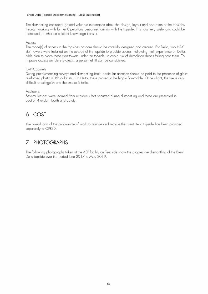
Brent Delta Topside Decommissioning – Close-out Report
46
The dismantling contractor gained valuable information about the design, layout and operation of the topsides through working with former Operations personnel familiar with the topside. This was very useful and could be increased to enhance efficient knowledge transfer. Access The mode(s) of access to the topsides onshore should be carefully designed and created. For Delta, two HAKI stair towers were installed on the outside of the topside to provide access. Following their experience on Delta, Able plan to place these stair towers under the topside, to avoid risk of demolition debris falling onto them. To improve access on future projects, a personnel lift can be considered. GRP Cabinets During pre-dismantling surveys and dismantling itself, particular attention should be paid to the presence of glass-reinforced plastic (GRP) cabinets. On Delta, these proved to be highly flammable. Once alight, the fire is very difficult to extinguish and the smoke is toxic. Accidents Several lessons were learned from accidents that occurred during dismantling and these are presented in Section 4 under Health and Safety.
6 COST
The overall cost of the programme of work to remove and recycle the Brent Delta topside has been provided separately to OPRED.
7 PHOTOGRAPHS
The following photographs taken at the ASP facility on Teesside show the progressive dismantling of the Brent Delta topside over the period June 2017 to May 2019.
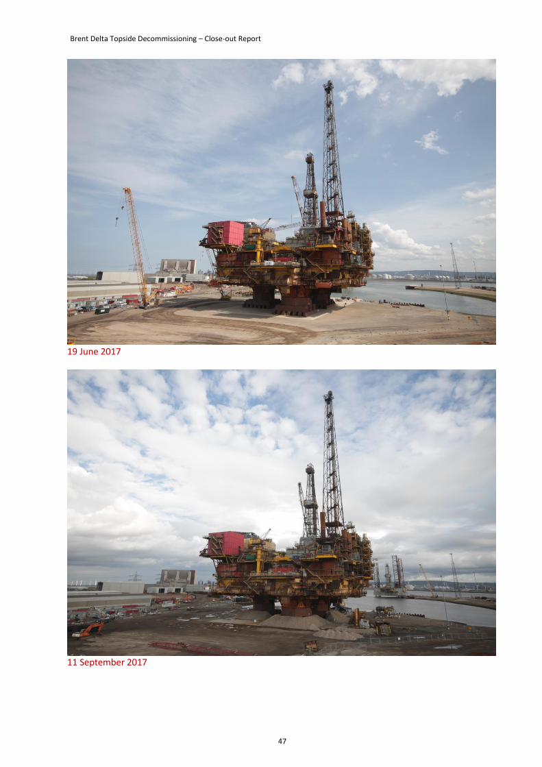
Brent Delta Topside Decommissioning – Close-out Report
47
19 June 2017
11 September 2017
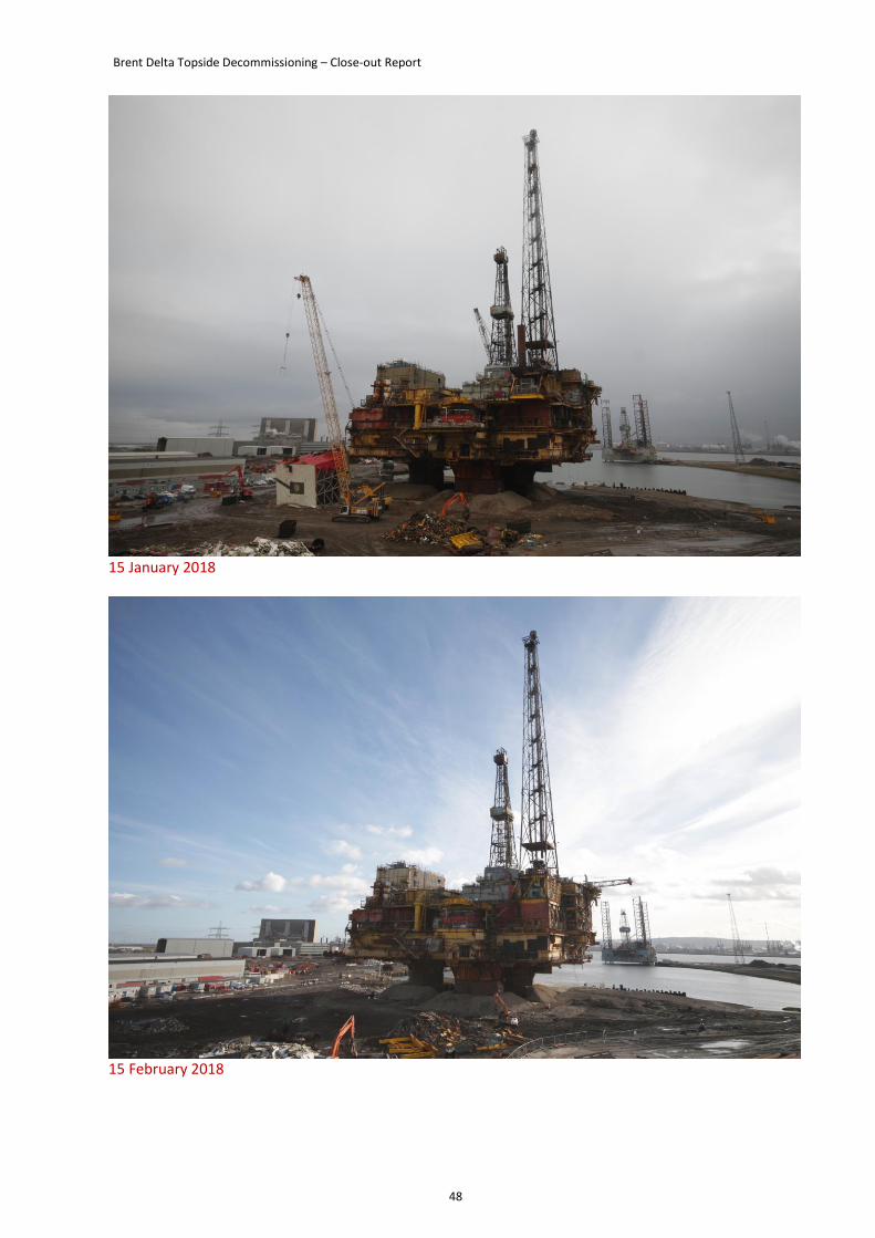
Brent Delta Topside Decommissioning – Close-out Report
48
15 January 2018
15 February 2018
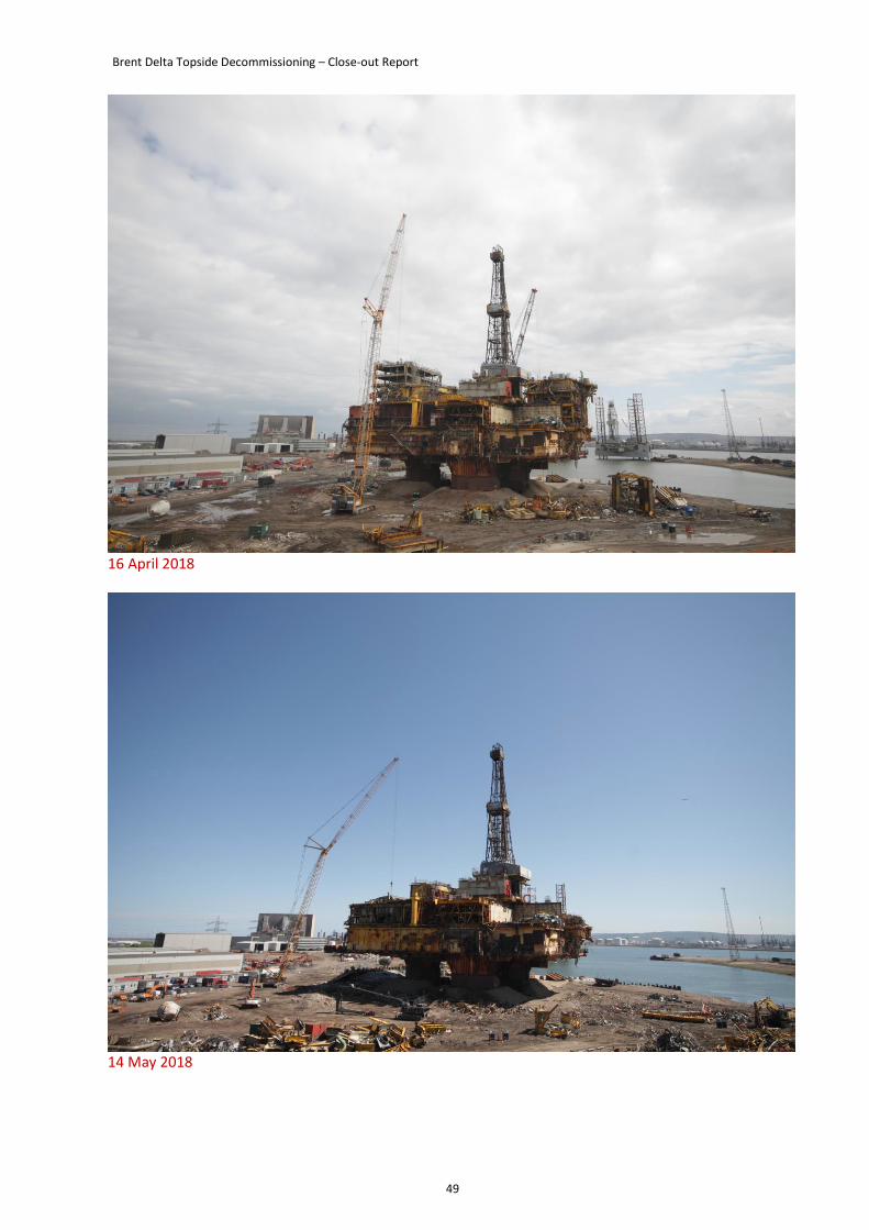
Brent Delta Topside Decommissioning – Close-out Report
49
16 April 2018
14 May 2018
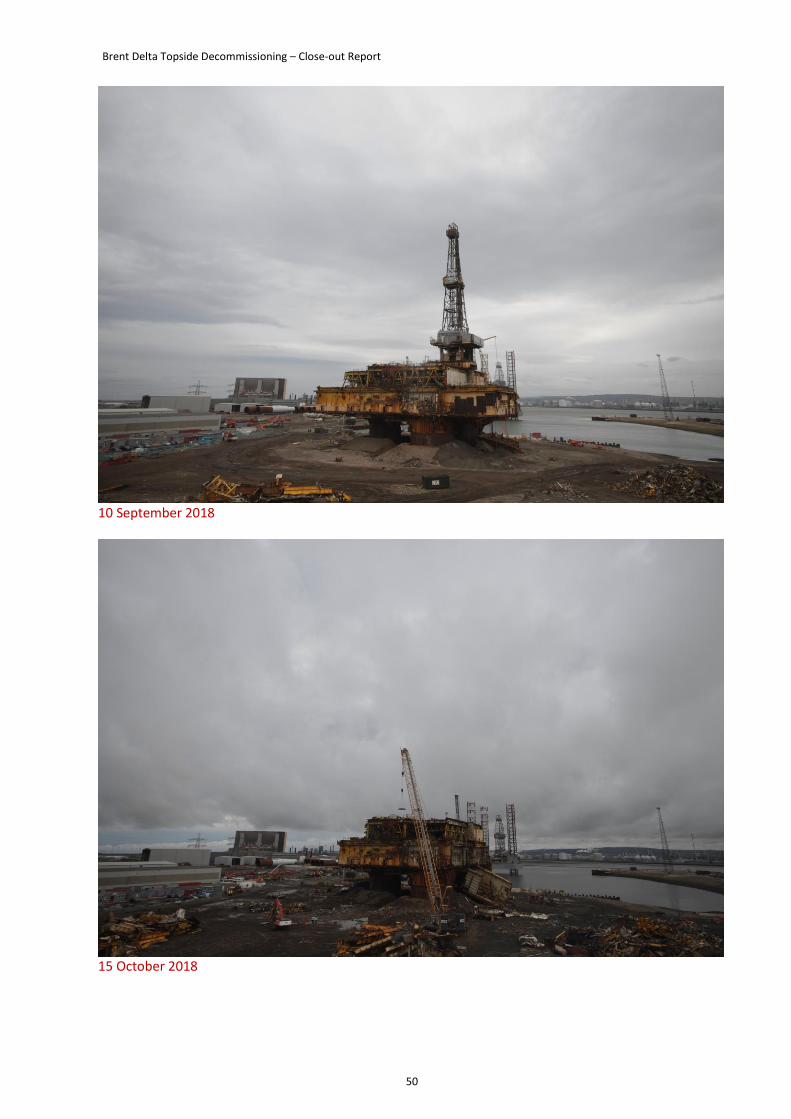
Brent Delta Topside Decommissioning – Close-out Report
50
10 September 2018
15 October 2018
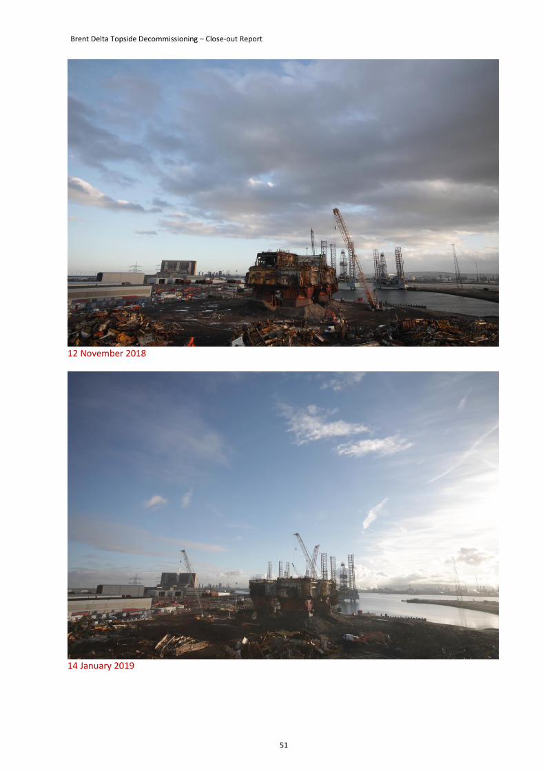
Brent Delta Topside Decommissioning – Close-out Report
51
12 November 2018
14 January 2019
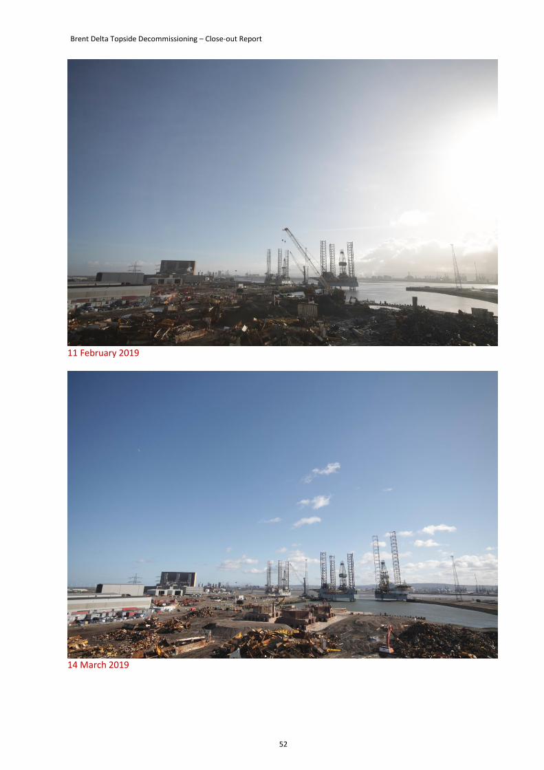
Brent Delta Topside Decommissioning – Close-out Report
52
11 February 2019
14 March 2019
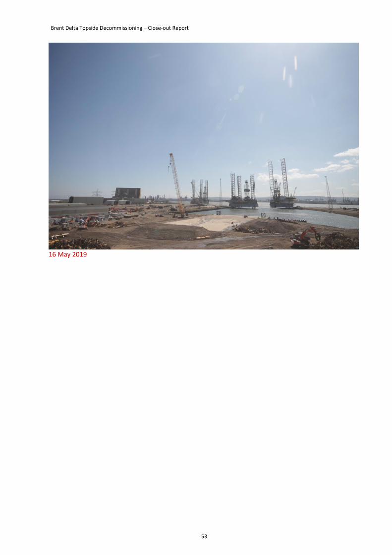
Brent Delta Topside Decommissioning – Close-out Report
53
16 May 2019