Embed Size (px)
DESCRIPTION
A brief regarding the Break system
Citation preview
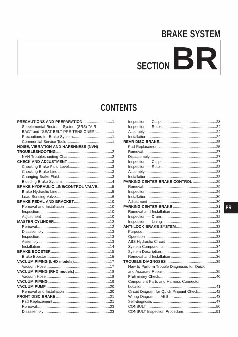
BRAKE SYSTEM
SECTIONBRCONTENTS
PRECAUTIONS AND PREPARATION ............................1Supplemental Restraint System (SRS) ‘‘AIRBAG’’ and ‘‘SEAT BELT PRE-TENSIONER’’...............1Precautions for Brake System.....................................1Commercial Service Tools ...........................................1
NOISE, VIBRATION AND HARSHNESS (NVH)TROUBLESHOOTING .....................................................2
NVH Troubleshooting Chart.........................................2CHECK AND ADJUSTMENT ..........................................3
Checking Brake Fluid Level.........................................3Checking Brake Line ...................................................3Changing Brake Fluid ..................................................3Bleeding Brake System ...............................................4
BRAKE HYDRAULIC LINE/CONTROL VALVE ..............5Brake Hydraulic Line ...................................................5Load Sensing Valve.....................................................6
BRAKE PEDAL AND BRACKET ..................................10Removal and Installation ...........................................10Inspection...................................................................10Adjustment .................................................................10
MASTER CYLINDER .....................................................12Removal.....................................................................12Disassembly...............................................................13Inspection...................................................................13Assembly ...................................................................13Installation..................................................................14
BRAKE BOOSTER ........................................................15Brake Booster ............................................................15
VACUUM PIPING (LHD models) ..................................17Vacuum Hose ............................................................17
VACUUM PIPING (RHD models) .................................18Vacuum Hose ............................................................18
VACUUM PIPING...........................................................19VACUUM PUMP ............................................................20
Removal and Installation ...........................................20FRONT DISC BRAKE ...................................................21
Pad Replacement ......................................................21Removal.....................................................................23Disassembly...............................................................23
Inspection — Caliper .................................................23Inspection — Rotor....................................................24Assembly ...................................................................24Installation..................................................................24
REAR DISC BRAKE ......................................................25Pad Replacement ......................................................25Removal.....................................................................27Disassembly...............................................................27Inspection — Caliper .................................................27Inspection — Rotor....................................................28Assembly ...................................................................28Installation..................................................................28
PARKING CENTER BRAKE CONTROL ......................29Removal.....................................................................29Inspection...................................................................29Installation..................................................................30Adjustment .................................................................30
PARKING CENTER BRAKE .........................................31Removal and Installation ...........................................31Inspection — Drum....................................................32Inspection — Lining ...................................................32
ANTI-LOCK BRAKE SYSTEM ......................................33Purpose......................................................................33Operation ...................................................................33ABS Hydraulic Circuit ................................................33System Components .................................................34System Description....................................................34Removal and Installation ...........................................36
TROUBLE DIAGNOSES ...............................................39How to Perform Trouble Diagnoses for Quickand Accurate Repair ..................................................39Preliminary Check......................................................40Component Parts and Harness ConnectorLocation .....................................................................41Circuit Diagram for Quick Pinpoint Check.................42Wiring Diagram — ABS — ........................................43Self-diagnosis ............................................................47CONSULT ..................................................................50CONSULT Inspection Procedure...............................51
BR
Ground Circuit Check ................................................56TROUBLE DIAGNOSES FOR SELF-DIAGNOSTICITEMS.............................................................................57
Diagnostic Procedure 1 (Wheel sensor or rotor) ......57Diagnostic Procedure 2 (ABS actuator solenoidvalve and solenoid valve relay) .................................59Diagnostic Procedure 3 (Motor relay or motor).........61Diagnostic Procedure 4 (Low voltage) ......................63Diagnostic Procedure 5 (G sensor)...........................64Diagnostic Procedure 6 (Control unit) .......................65
TROUBLE DIAGNOSES FOR SYMPTOMS .................66Diagnostic Procedure 7 (ABS works frequently.) ......66Diagnostic Procedure 8 (Unexpected pedalaction) ........................................................................67
Diagnostic Procedure 9 (Long stopping distance) ....67Diagnostic Procedure 10 (ABS does not work.) .......68Diagnostic Procedure 11 (Pedal vibration andnoise) .........................................................................68Diagnostic Procedure 12 (Warning lamp doesnot come on when ignition switch is turned ON.) .....69Diagnostic Procedure 13 (Warning lamp stays onwhen ignition switch is turned ON.)...........................71
SERVICE DATA AND SPECIFICATIONS (SDS) ..........72General Specifications...............................................72Inspection and Adjustment ........................................73
When you read wiring diagrams:+ Read GI section, ‘‘HOW TO READ WIRING DIAGRAMS’’.+ See EL section, ‘‘POWER SUPPLY ROUTING’’ for power distribution circuit.When you perform trouble diagnoses, read GI section, ‘‘HOW TO FOLLOW FLOW CHARTIN TROUBLE DIAGNOSES’’ and ‘‘HOW TO PERFORM EFFICIENT DIAGNOSIS FOR ANELECTRICAL INCIDENT’’.
Supplemental Restraint System (SRS) ‘‘AIRBAG’’ and ‘‘SEAT BELT PRE-TENSIONER’’
The Supplemental Restraint System such as ‘‘AIR BAG’’ and ‘‘SEAT BELT PRE-TENSIONER’’ used along witha seat belt, helps to reduce the risk or severity of injury to the driver and front passenger in a frontal collision.The SRS system composition which is available to NISSAN MODEL Y61 is as follows (The composition var-ies according to the destination.):Driver air bag module (located in the center of the steering wheel), front passenger air bag module (locatedon the instrument panel on passenger side), seat belt pre-tensioner, a diagnosis sensor unit, warning lamp,wiring harness and spiral cable.Information necessary to service the system safely is included in the RS section of this Service Manual.WARNING:+ To avoid rendering the SRS inoperative, which could increase the risk of personal injury or death
in the event of a collision which would result in air bag inflation, all maintenance must be performedby an authorized NISSAN dealer.
+ Improper maintenance, including incorrect removal and installation of the SRS, can lead to per-sonal injury caused by unintentional activation of the system. For removal of Spiral Cable and AirBag Module, see the RS section.
+ Do not use electrical test equipment on any circuit related to the SRS unless instructed to in thisService Manual. Spiral Cable and wiring harnesses covered with yellow insulation either just beforethe harness connectors or for the complete harness are related to the SRS.
Precautions for Brake System+ Use brake fluid ‘‘DOT 3’’.+ Never reuse drained brake fluid.+ Be careful not to splash brake fluid on painted areas; it
may cause paint damage. If brake fluid is splashed onpainted areas, wash it away with water immediately.
+ To clean master cylinder parts, disc brake caliper parts orwheel cylinder parts, use clean brake fluid.
+ Never use mineral oils such as gasoline or kerosene. Theywill ruin rubber parts of hydraulic system.
+ Use flare nut wrench when removing and installing braketubes.
+ Always torque brake lines when installing.WARNING:Clean brakes with a vacuum dust collector to minimize risk ofhealth hazard from powder caused by friction.
Commercial Service Tools
Tool name Description
j1 Flare nut crowfootj2 Torque wrench
NT360
Removing and installing each brake piping
a: 10 mm (0.39 in)
Brake fluid pressure gauge
NT151
Measuring brake fluid pressure
SBR686C
PRECAUTIONS AND PREPARATION
BR-1
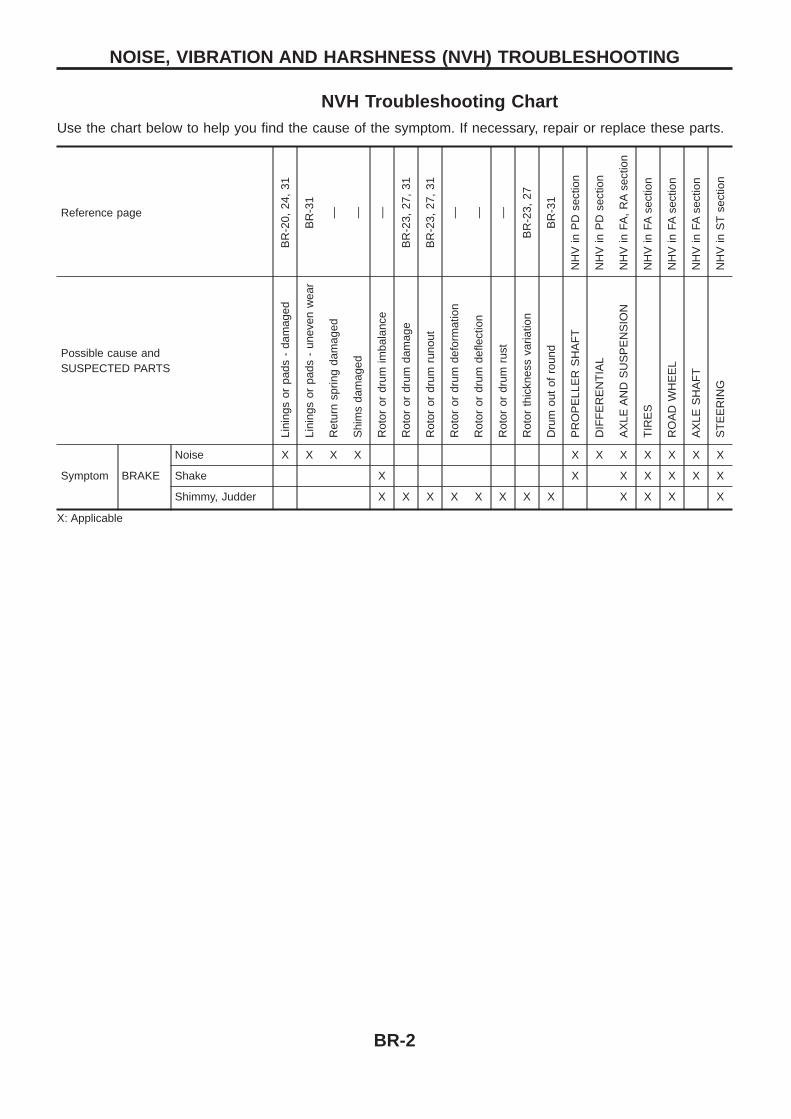
NVH Troubleshooting ChartUse the chart below to help you find the cause of the symptom. If necessary, repair or replace these parts.
Reference page
BR
-20,
24,
31
BR
-31
— — —
BR
-23,
27,
31
BR
-23,
27,
31
— — —
BR
-23,
27
BR
-31
NH
Vin
PD
sect
ion
NH
Vin
PD
sect
ion
NH
Vin
FA,
RA
sect
ion
NH
Vin
FAse
ctio
n
NH
Vin
FAse
ctio
n
NH
Vin
FAse
ctio
n
NH
Vin
ST
sect
ion
Possible cause andSUSPECTED PARTS
Lini
ngs
orpa
ds-
dam
aged
Lini
ngs
orpa
ds-
unev
enw
ear
Ret
urn
sprin
gda
mag
ed
Shi
ms
dam
aged
Rot
oror
drum
imba
lanc
e
Rot
oror
drum
dam
age
Rot
oror
drum
runo
ut
Rot
oror
drum
defo
rmat
ion
Rot
oror
drum
defle
ctio
n
Rot
oror
drum
rust
Rot
orth
ickn
ess
varia
tion
Dru
mou
tof
roun
d
PR
OP
ELL
ER
SH
AF
T
DIF
FE
RE
NT
IAL
AX
LEA
ND
SU
SP
EN
SIO
N
TIR
ES
RO
AD
WH
EE
L
AX
LES
HA
FT
ST
EE
RIN
G
Symptom BRAKE
Noise X X X X X X X X X X X
Shake X X X X X X X
Shimmy, Judder X X X X X X X X X X X X
X: Applicable
NOISE, VIBRATION AND HARSHNESS (NVH) TROUBLESHOOTING
BR-2
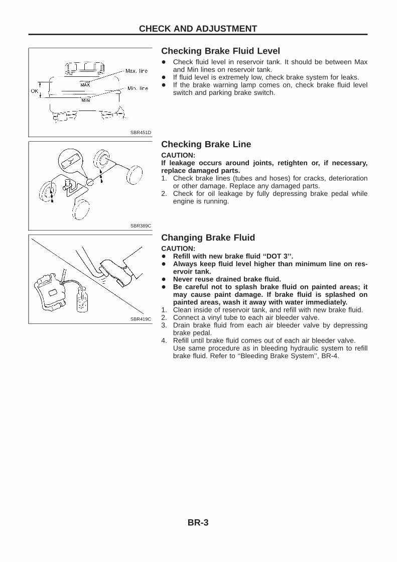
Checking Brake Fluid Level+ Check fluid level in reservoir tank. It should be between Max
and Min lines on reservoir tank.+ If fluid level is extremely low, check brake system for leaks.+ If the brake warning lamp comes on, check brake fluid level
switch and parking brake switch.
Checking Brake LineCAUTION:If leakage occurs around joints, retighten or, if necessary,replace damaged parts.1. Check brake lines (tubes and hoses) for cracks, deterioration
or other damage. Replace any damaged parts.2. Check for oil leakage by fully depressing brake pedal while
engine is running.
Changing Brake FluidCAUTION:+ Refill with new brake fluid ‘‘DOT 3’’.+ Always keep fluid level higher than minimum line on res-
ervoir tank.+ Never reuse drained brake fluid.+ Be careful not to splash brake fluid on painted areas; it
may cause paint damage. If brake fluid is splashed onpainted areas, wash it away with water immediately.
1. Clean inside of reservoir tank, and refill with new brake fluid.2. Connect a vinyl tube to each air bleeder valve.3. Drain brake fluid from each air bleeder valve by depressing
brake pedal.4. Refill until brake fluid comes out of each air bleeder valve.
Use same procedure as in bleeding hydraulic system to refillbrake fluid. Refer to ‘‘Bleeding Brake System’’, BR-4.
SBR451D
SBR389C
SBR419C
CHECK AND ADJUSTMENT
BR-3
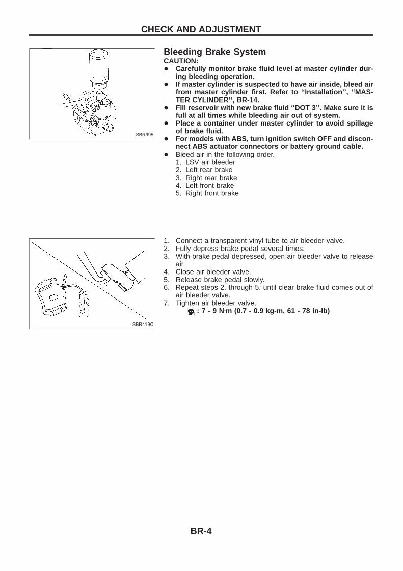
Bleeding Brake SystemCAUTION:+ Carefully monitor brake fluid level at master cylinder dur-
ing bleeding operation.+ If master cylinder is suspected to have air inside, bleed air
from master cylinder first. Refer to ‘‘Installation’’, ‘‘MAS-TER CYLINDER’’, BR-14.
+ Fill reservoir with new brake fluid ‘‘DOT 3’’. Make sure it isfull at all times while bleeding air out of system.
+ Place a container under master cylinder to avoid spillageof brake fluid.
+ For models with ABS, turn ignition switch OFF and discon-nect ABS actuator connectors or battery ground cable.
+ Bleed air in the following order.1. LSV air bleeder2. Left rear brake3. Right rear brake4. Left front brake5. Right front brake
1. Connect a transparent vinyl tube to air bleeder valve.2. Fully depress brake pedal several times.3. With brake pedal depressed, open air bleeder valve to release
air.4. Close air bleeder valve.5. Release brake pedal slowly.6. Repeat steps 2. through 5. until clear brake fluid comes out of
air bleeder valve.7. Tighten air bleeder valve.
: 7 - 9 Nzm (0.7 - 0.9 kg-m, 61 - 78 in-lb)
SBR995
SBR419C
CHECK AND ADJUSTMENT
BR-4
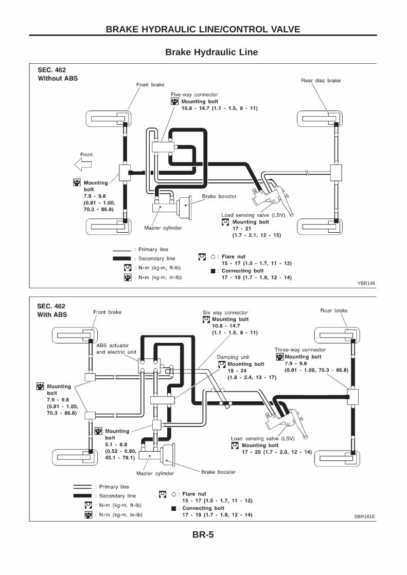
Brake Hydraulic Line
YBR146
SBR161E
BRAKE HYDRAULIC LINE/CONTROL VALVE
BR-5
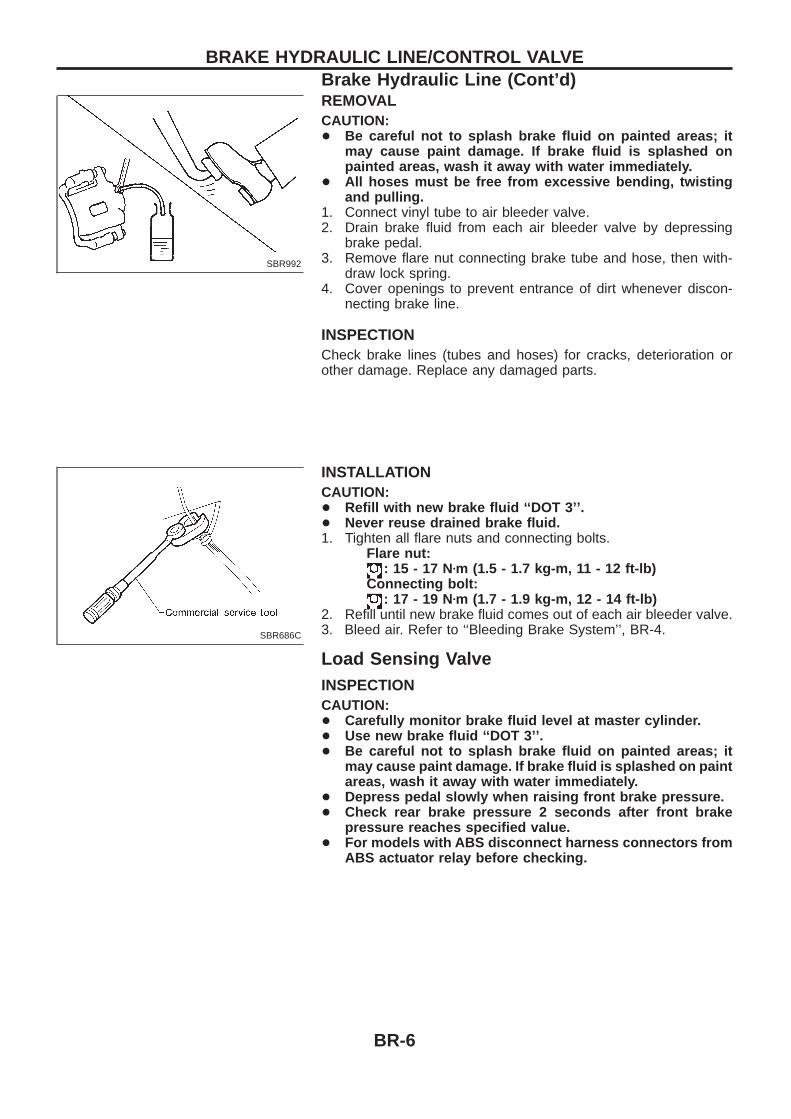
REMOVALCAUTION:+ Be careful not to splash brake fluid on painted areas; it
may cause paint damage. If brake fluid is splashed onpainted areas, wash it away with water immediately.
+ All hoses must be free from excessive bending, twistingand pulling.
1. Connect vinyl tube to air bleeder valve.2. Drain brake fluid from each air bleeder valve by depressing
brake pedal.3. Remove flare nut connecting brake tube and hose, then with-
draw lock spring.4. Cover openings to prevent entrance of dirt whenever discon-
necting brake line.
INSPECTIONCheck brake lines (tubes and hoses) for cracks, deterioration orother damage. Replace any damaged parts.
INSTALLATIONCAUTION:+ Refill with new brake fluid ‘‘DOT 3’’.+ Never reuse drained brake fluid.1. Tighten all flare nuts and connecting bolts.
Flare nut:: 15 - 17 Nzm (1.5 - 1.7 kg-m, 11 - 12 ft-lb)
Connecting bolt:: 17 - 19 Nzm (1.7 - 1.9 kg-m, 12 - 14 ft-lb)
2. Refill until new brake fluid comes out of each air bleeder valve.3. Bleed air. Refer to ‘‘Bleeding Brake System’’, BR-4.
Load Sensing ValveINSPECTIONCAUTION:+ Carefully monitor brake fluid level at master cylinder.+ Use new brake fluid ‘‘DOT 3’’.+ Be careful not to splash brake fluid on painted areas; it
may cause paint damage. If brake fluid is splashed on paintareas, wash it away with water immediately.
+ Depress pedal slowly when raising front brake pressure.+ Check rear brake pressure 2 seconds after front brake
pressure reaches specified value.+ For models with ABS disconnect harness connectors from
ABS actuator relay before checking.
SBR992
SBR686C
BRAKE HYDRAULIC LINE/CONTROL VALVEBrake Hydraulic Line (Cont’d)
BR-6
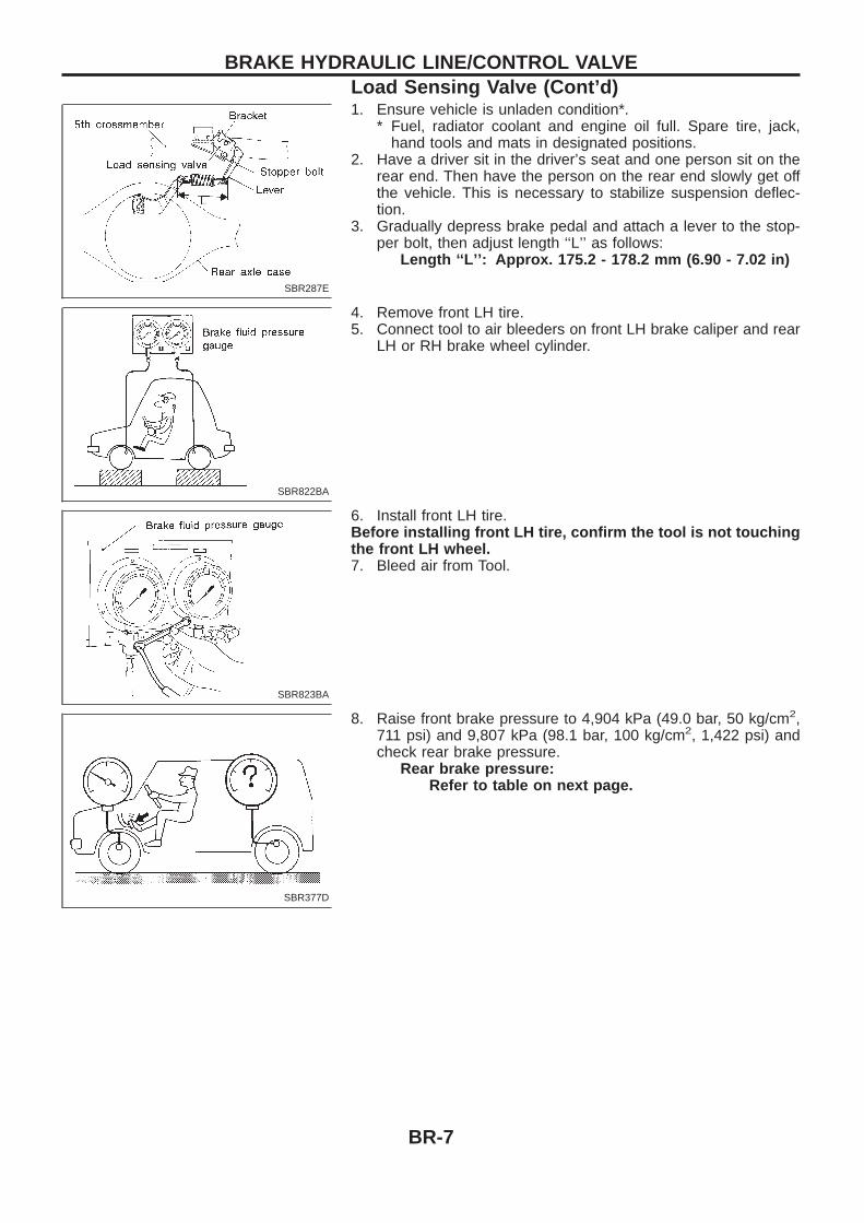
1. Ensure vehicle is unladen condition*.* Fuel, radiator coolant and engine oil full. Spare tire, jack,
hand tools and mats in designated positions.2. Have a driver sit in the driver’s seat and one person sit on the
rear end. Then have the person on the rear end slowly get offthe vehicle. This is necessary to stabilize suspension deflec-tion.
3. Gradually depress brake pedal and attach a lever to the stop-per bolt, then adjust length ‘‘L’’ as follows:
Length ‘‘L’’: Approx. 175.2 - 178.2 mm (6.90 - 7.02 in)
4. Remove front LH tire.5. Connect tool to air bleeders on front LH brake caliper and rear
LH or RH brake wheel cylinder.
6. Install front LH tire.Before installing front LH tire, confirm the tool is not touchingthe front LH wheel.7. Bleed air from Tool.
8. Raise front brake pressure to 4,904 kPa (49.0 bar, 50 kg/cm2,711 psi) and 9,807 kPa (98.1 bar, 100 kg/cm2, 1,422 psi) andcheck rear brake pressure.
Rear brake pressure:Refer to table on next page.
SBR287E
SBR822BA
SBR823BA
SBR377D
BRAKE HYDRAULIC LINE/CONTROL VALVELoad Sensing Valve (Cont’d)
BR-7
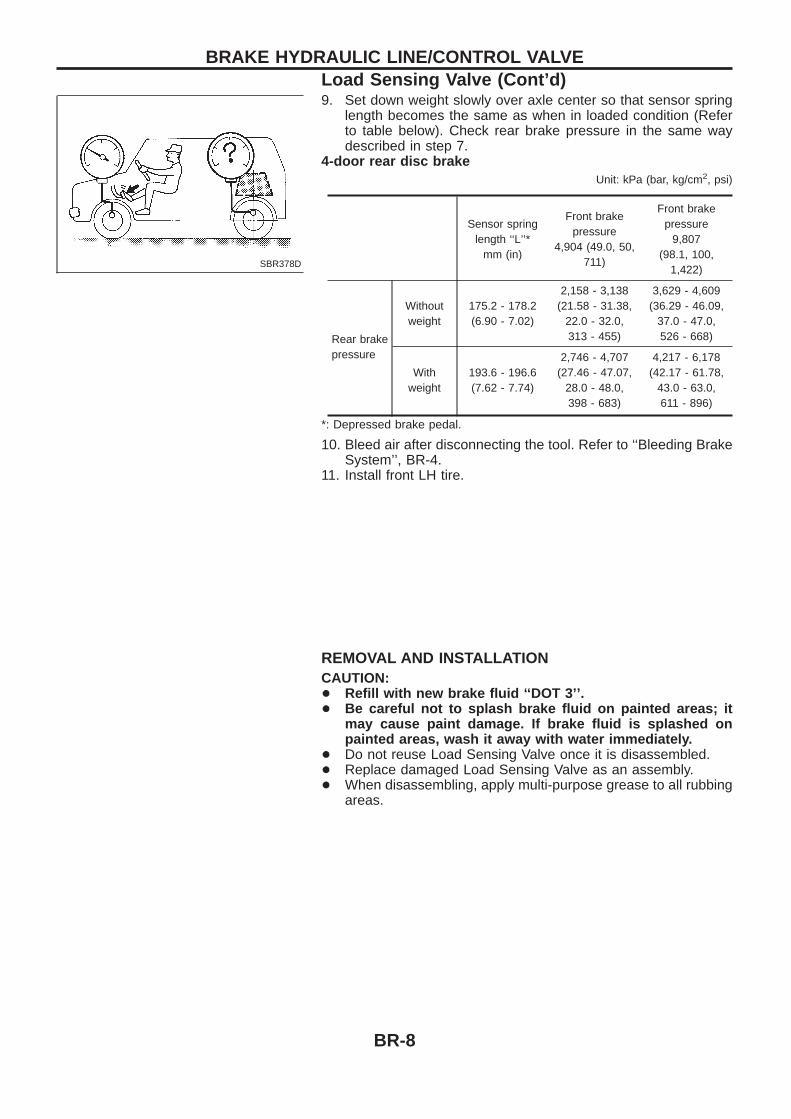
9. Set down weight slowly over axle center so that sensor springlength becomes the same as when in loaded condition (Referto table below). Check rear brake pressure in the same waydescribed in step 7.
4-door rear disc brakeUnit: kPa (bar, kg/cm2, psi)
Sensor springlength ‘‘L’’*
mm (in)
Front brakepressure
4,904 (49.0, 50,711)
Front brakepressure
9,807(98.1, 100,
1,422)
Rear brakepressure
Withoutweight
175.2 - 178.2(6.90 - 7.02)
2,158 - 3,138(21.58 - 31.38,
22.0 - 32.0,313 - 455)
3,629 - 4,609(36.29 - 46.09,
37.0 - 47.0,526 - 668)
Withweight
193.6 - 196.6(7.62 - 7.74)
2,746 - 4,707(27.46 - 47.07,
28.0 - 48.0,398 - 683)
4,217 - 6,178(42.17 - 61.78,
43.0 - 63.0,611 - 896)
*: Depressed brake pedal.
10. Bleed air after disconnecting the tool. Refer to ‘‘Bleeding BrakeSystem’’, BR-4.
11. Install front LH tire.
REMOVAL AND INSTALLATIONCAUTION:+ Refill with new brake fluid ‘‘DOT 3’’.+ Be careful not to splash brake fluid on painted areas; it
may cause paint damage. If brake fluid is splashed onpainted areas, wash it away with water immediately.
+ Do not reuse Load Sensing Valve once it is disassembled.+ Replace damaged Load Sensing Valve as an assembly.+ When disassembling, apply multi-purpose grease to all rubbing
areas.
SBR378D
BRAKE HYDRAULIC LINE/CONTROL VALVELoad Sensing Valve (Cont’d)
BR-8
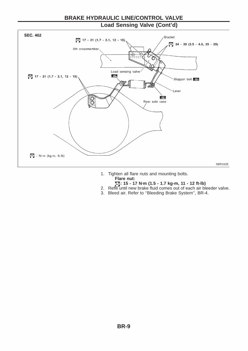
1. Tighten all flare nuts and mounting bolts.Flare nut:
: 15 - 17 Nzm (1.5 - 1.7 kg-m, 11 - 12 ft-lb)2. Refill until new brake fluid comes out of each air bleeder valve.3. Bleed air. Refer to ‘‘Bleeding Brake System’’, BR-4.
SBR162E
BRAKE HYDRAULIC LINE/CONTROL VALVELoad Sensing Valve (Cont’d)
BR-9
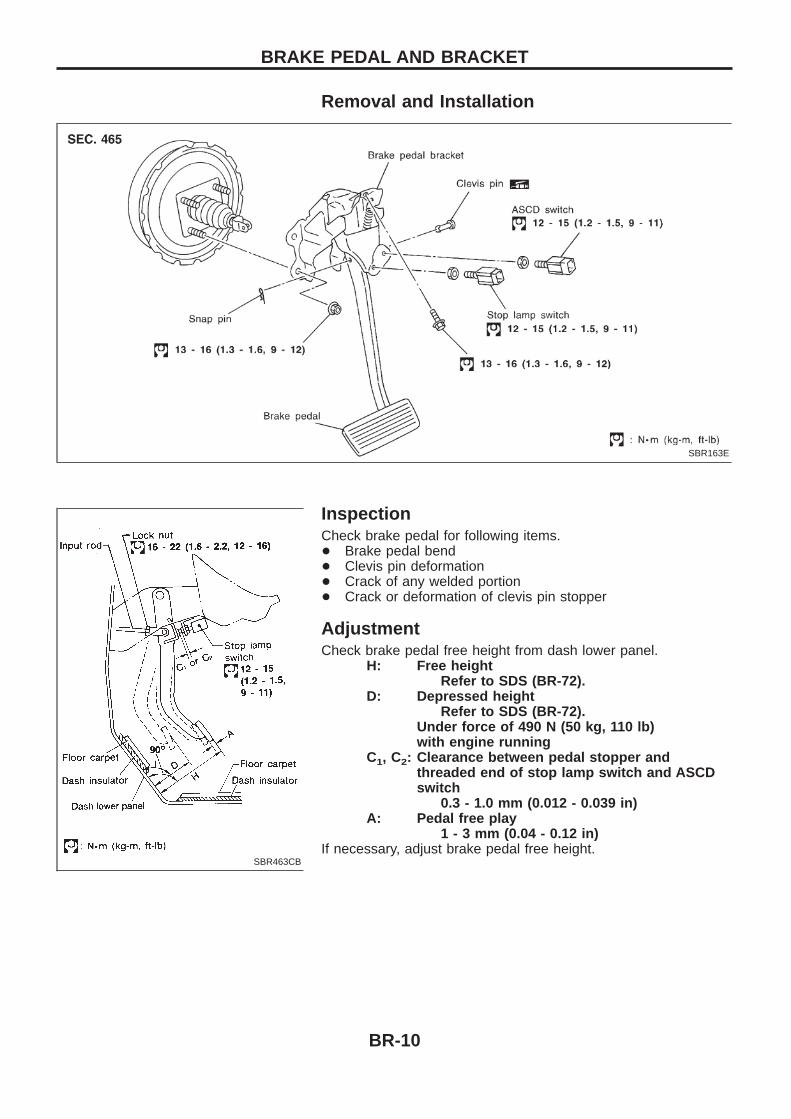
Removal and Installation
InspectionCheck brake pedal for following items.+ Brake pedal bend+ Clevis pin deformation+ Crack of any welded portion+ Crack or deformation of clevis pin stopper
AdjustmentCheck brake pedal free height from dash lower panel.
H: Free heightRefer to SDS (BR-72).
D: Depressed heightRefer to SDS (BR-72).
Under force of 490 N (50 kg, 110 lb)with engine running
C1, C2: Clearance between pedal stopper andthreaded end of stop lamp switch and ASCDswitch
0.3 - 1.0 mm (0.012 - 0.039 in)A: Pedal free play
1 - 3 mm (0.04 - 0.12 in)If necessary, adjust brake pedal free height.
SBR163E
SBR463CB
BRAKE PEDAL AND BRACKET
BR-10
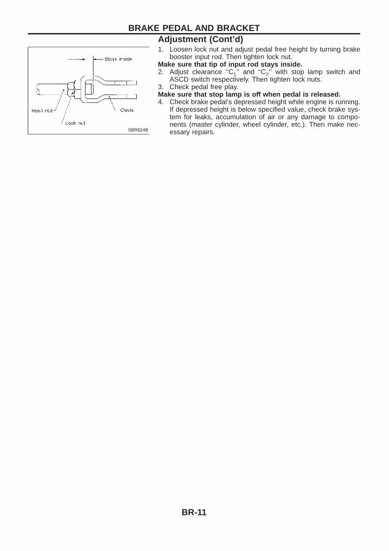
1. Loosen lock nut and adjust pedal free height by turning brakebooster input rod. Then tighten lock nut.
Make sure that tip of input rod stays inside.2. Adjust clearance ‘‘C1’’ and ‘‘C2’’ with stop lamp switch and
ASCD switch respectively. Then tighten lock nuts.3. Check pedal free play.Make sure that stop lamp is off when pedal is released.4. Check brake pedal’s depressed height while engine is running.
If depressed height is below specified value, check brake sys-tem for leaks, accumulation of air or any damage to compo-nents (master cylinder, wheel cylinder, etc.). Then make nec-essary repairs.SBR824B
BRAKE PEDAL AND BRACKETAdjustment (Cont’d)
BR-11
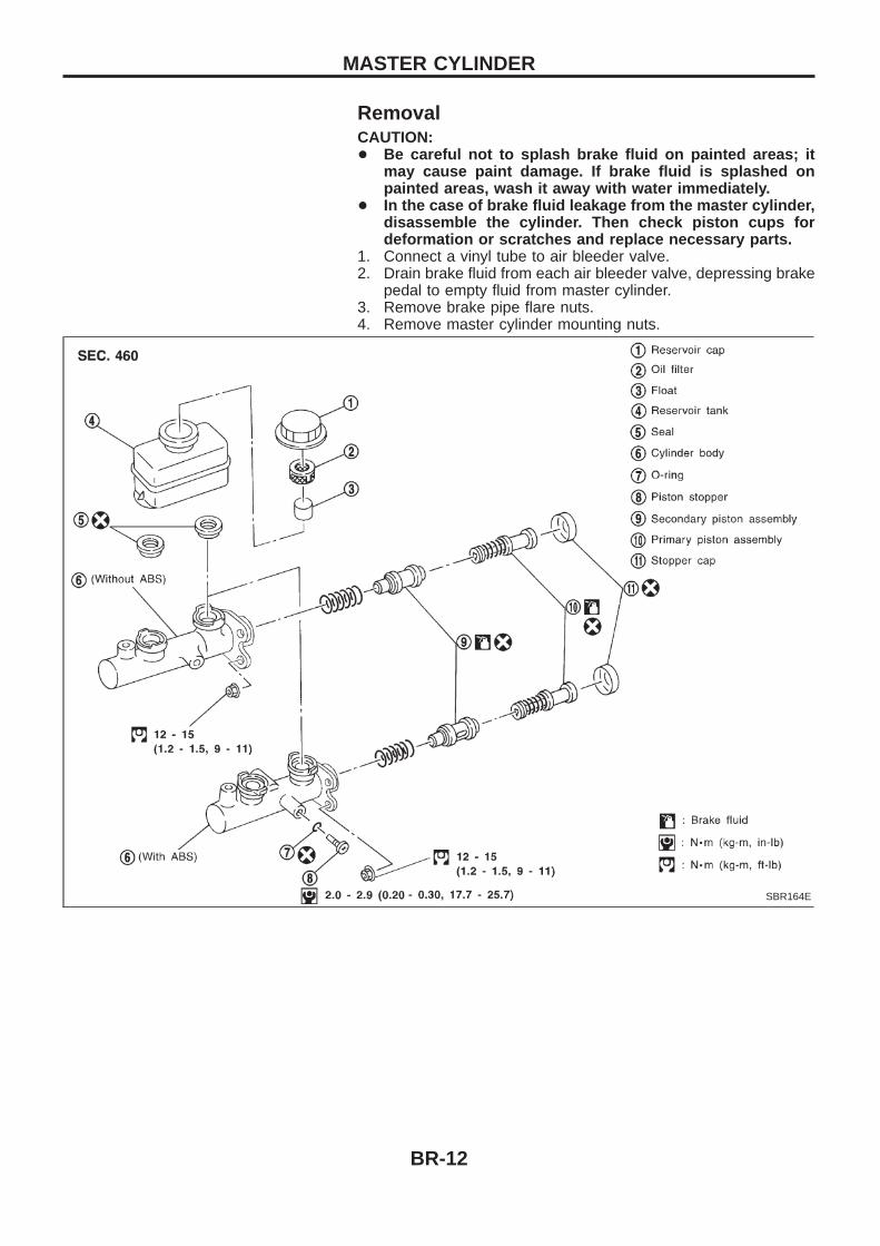
RemovalCAUTION:+ Be careful not to splash brake fluid on painted areas; it
may cause paint damage. If brake fluid is splashed onpainted areas, wash it away with water immediately.
+ In the case of brake fluid leakage from the master cylinder,disassemble the cylinder. Then check piston cups fordeformation or scratches and replace necessary parts.
1. Connect a vinyl tube to air bleeder valve.2. Drain brake fluid from each air bleeder valve, depressing brake
pedal to empty fluid from master cylinder.3. Remove brake pipe flare nuts.4. Remove master cylinder mounting nuts.
SBR164E
MASTER CYLINDER
BR-12
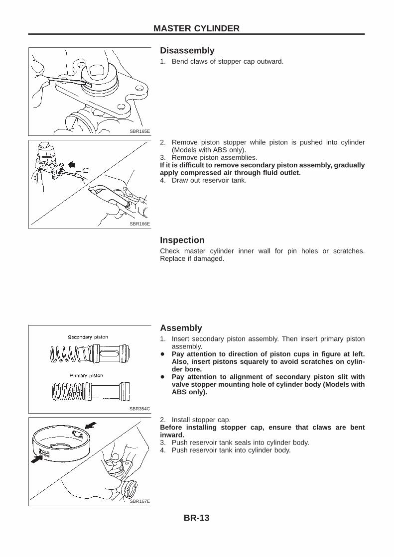
Disassembly1. Bend claws of stopper cap outward.
2. Remove piston stopper while piston is pushed into cylinder(Models with ABS only).
3. Remove piston assemblies.If it is difficult to remove secondary piston assembly, graduallyapply compressed air through fluid outlet.4. Draw out reservoir tank.
InspectionCheck master cylinder inner wall for pin holes or scratches.Replace if damaged.
Assembly1. Insert secondary piston assembly. Then insert primary piston
assembly.+ Pay attention to direction of piston cups in figure at left.
Also, insert pistons squarely to avoid scratches on cylin-der bore.
+ Pay attention to alignment of secondary piston slit withvalve stopper mounting hole of cylinder body (Models withABS only).
2. Install stopper cap.Before installing stopper cap, ensure that claws are bentinward.3. Push reservoir tank seals into cylinder body.4. Push reservoir tank into cylinder body.
SBR165E
SBR166E
SBR354C
SBR167E
MASTER CYLINDER
BR-13
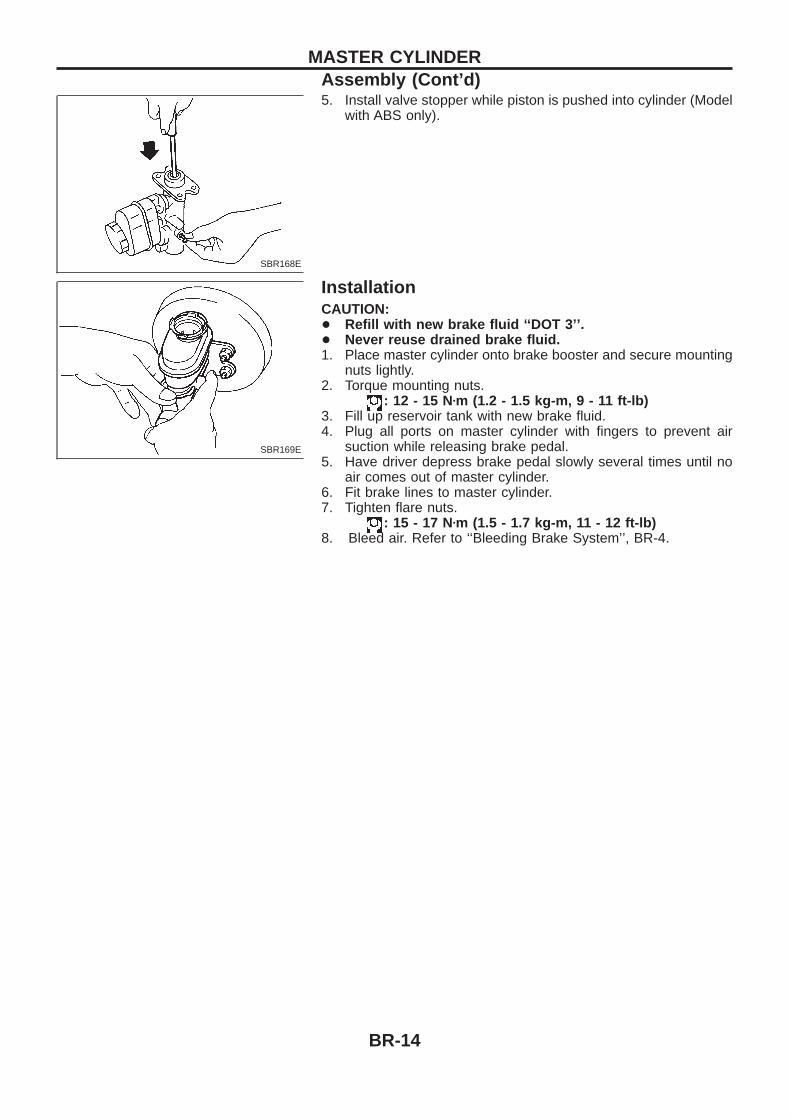
5. Install valve stopper while piston is pushed into cylinder (Modelwith ABS only).
InstallationCAUTION:+ Refill with new brake fluid ‘‘DOT 3’’.+ Never reuse drained brake fluid.1. Place master cylinder onto brake booster and secure mounting
nuts lightly.2. Torque mounting nuts.
: 12 - 15 Nzm (1.2 - 1.5 kg-m , 9 - 11 ft-lb)3. Fill up reservoir tank with new brake fluid.4. Plug all ports on master cylinder with fingers to prevent air
suction while releasing brake pedal.5. Have driver depress brake pedal slowly several times until no
air comes out of master cylinder.6. Fit brake lines to master cylinder.7. Tighten flare nuts.
: 15 - 17 Nzm (1.5 - 1.7 kg-m, 11 - 12 ft-lb)8. Bleed air. Refer to ‘‘Bleeding Brake System’’, BR-4.
SBR168E
SBR169E
MASTER CYLINDERAssembly (Cont’d)
BR-14
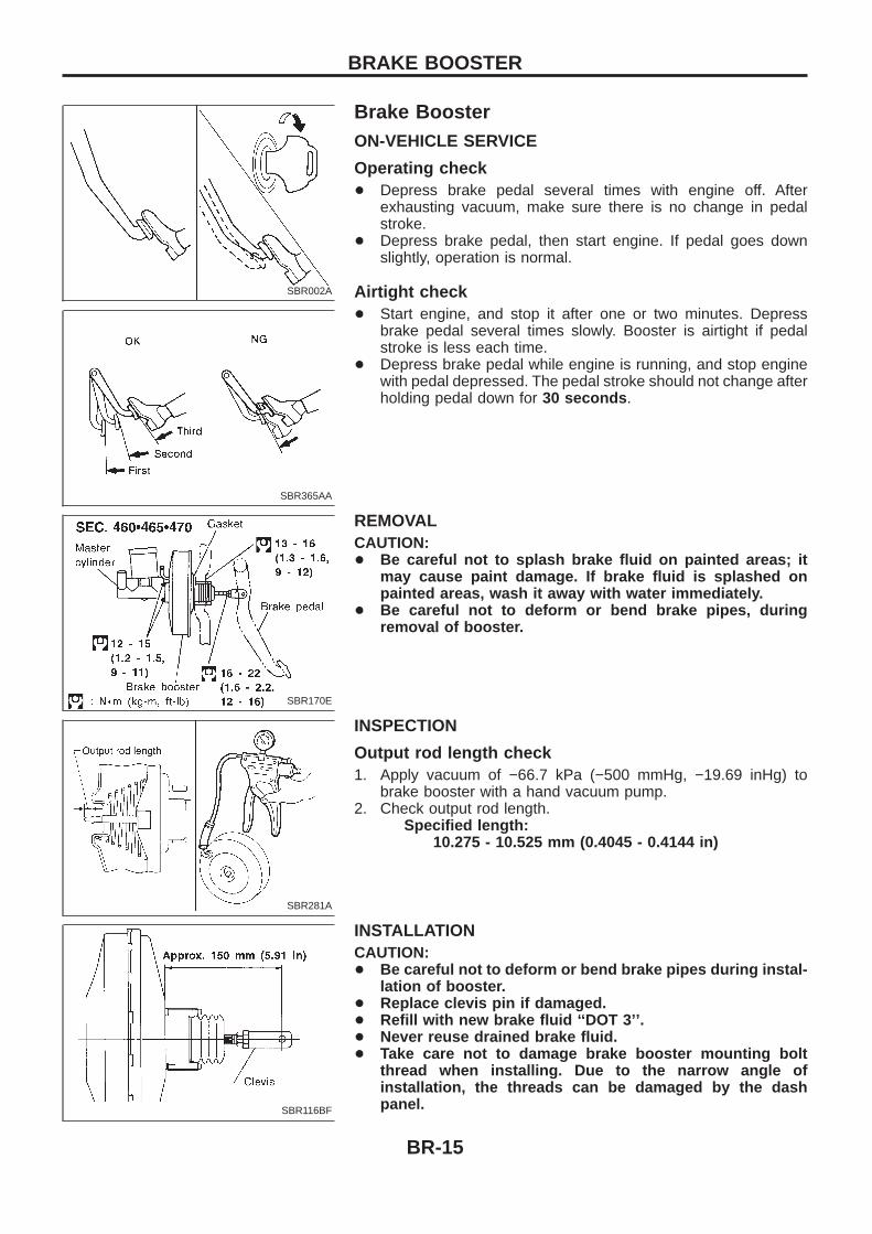
Brake BoosterON-VEHICLE SERVICE
Operating check+ Depress brake pedal several times with engine off. After
exhausting vacuum, make sure there is no change in pedalstroke.
+ Depress brake pedal, then start engine. If pedal goes downslightly, operation is normal.
Airtight check+ Start engine, and stop it after one or two minutes. Depress
brake pedal several times slowly. Booster is airtight if pedalstroke is less each time.
+ Depress brake pedal while engine is running, and stop enginewith pedal depressed. The pedal stroke should not change afterholding pedal down for 30 seconds .
REMOVALCAUTION:+ Be careful not to splash brake fluid on painted areas; it
may cause paint damage. If brake fluid is splashed onpainted areas, wash it away with water immediately.
+ Be careful not to deform or bend brake pipes, duringremoval of booster.
INSPECTION
Output rod length check1. Apply vacuum of −66.7 kPa (−500 mmHg, −19.69 inHg) to
brake booster with a hand vacuum pump.2. Check output rod length.
Specified length:10.275 - 10.525 mm (0.4045 - 0.4144 in)
INSTALLATIONCAUTION:+ Be careful not to deform or bend brake pipes during instal-
lation of booster.+ Replace clevis pin if damaged.+ Refill with new brake fluid ‘‘DOT 3’’.+ Never reuse drained brake fluid.+ Take care not to damage brake booster mounting bolt
thread when installing. Due to the narrow angle ofinstallation, the threads can be damaged by the dashpanel.
SBR002A
SBR365AA
SBR170E
SBR281A
SBR116BF
BRAKE BOOSTER
BR-15
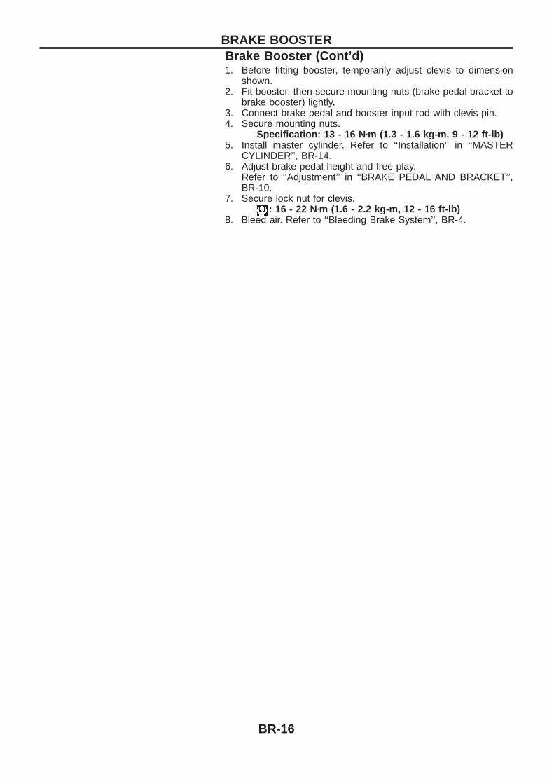
1. Before fitting booster, temporarily adjust clevis to dimensionshown.
2. Fit booster, then secure mounting nuts (brake pedal bracket tobrake booster) lightly.
3. Connect brake pedal and booster input rod with clevis pin.4. Secure mounting nuts.
Specification: 13 - 16 N zm (1.3 - 1.6 kg-m , 9 - 12 ft-lb)5. Install master cylinder. Refer to ‘‘Installation’’ in ‘‘MASTER
CYLINDER’’, BR-14.6. Adjust brake pedal height and free play.
Refer to ‘‘Adjustment’’ in ‘‘BRAKE PEDAL AND BRACKET’’,BR-10.
7. Secure lock nut for clevis.: 16 - 22 Nzm (1.6 - 2.2 kg-m, 12 - 16 ft-lb)
8. Bleed air. Refer to ‘‘Bleeding Brake System’’, BR-4.
BRAKE BOOSTERBrake Booster (Cont’d)
BR-16
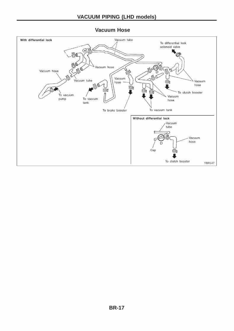
Vacuum Hose
YBR147
VACUUM PIPING (LHD models)
BR-17
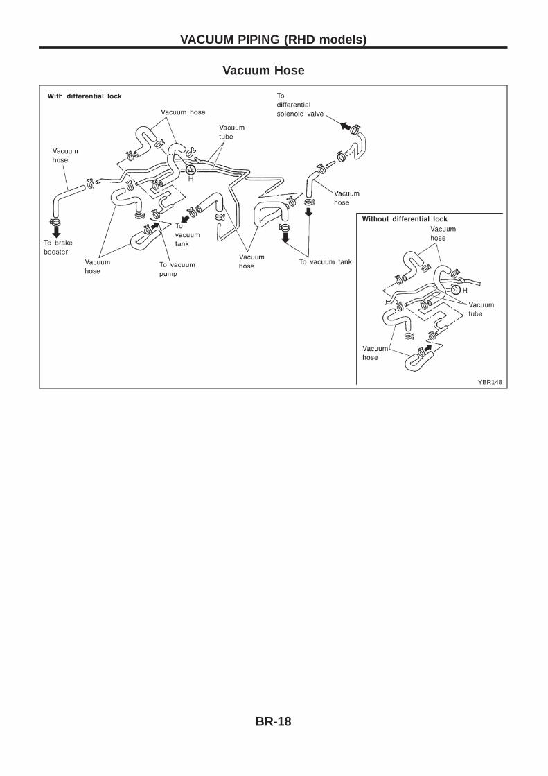
Vacuum Hose
YBR148
VACUUM PIPING (RHD models)
BR-18
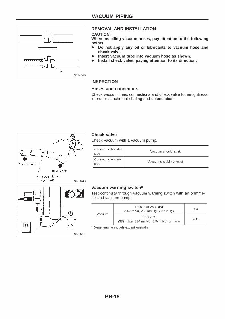
REMOVAL AND INSTALLATIONCAUTION:When installing vacuum hoses, pay attention to the followingpoints.+ Do not apply any oil or lubricants to vacuum hose and
check valve.+ Insert vacuum tube into vacuum hose as shown.+ Install check valve, paying attention to its direction.
INSPECTION
Hoses and connectorsCheck vacuum lines, connections and check valve for airtightness,improper attachment chafing and deterioration.
Check valveCheck vacuum with a vacuum pump.
Connect to boosterside
Vacuum should exist.
Connect to engineside
Vacuum should not exist.
Vacuum warning switch*Test continuity through vacuum warning switch with an ohmme-ter and vacuum pump.
Vacuum
Less than 26.7 kPa(267 mbar, 200 mmHg, 7.87 inHg)
0 Ω
33.3 kPa(333 mbar, 250 mmHg, 9.84 inHg) or more
∞ Ω
* Diesel engine models except Australia
SBR454D
SBR844B
SBR321E
VACUUM PIPING
BR-19
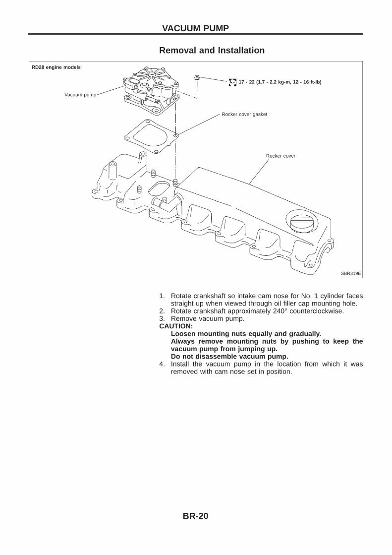
Removal and Installation
1. Rotate crankshaft so intake cam nose for No. 1 cylinder facesstraight up when viewed through oil filler cap mounting hole.
2. Rotate crankshaft approximately 240° counterclockwise.3. Remove vacuum pump.CAUTION:
Loosen mounting nuts equally and gradually.Always remove mounting nuts by pushing to keep thevacuum pump from jumping up.Do not disassemble vacuum pump.
4. Install the vacuum pump in the location from which it wasremoved with cam nose set in position.
SBR319E
RD28 engine models
Vacuum pump
17 - 22 (1.7 - 2.2 kg-m, 12 - 16 ft-lb)
Rocker cover gasket
Rocker cover
VACUUM PUMP
BR-20
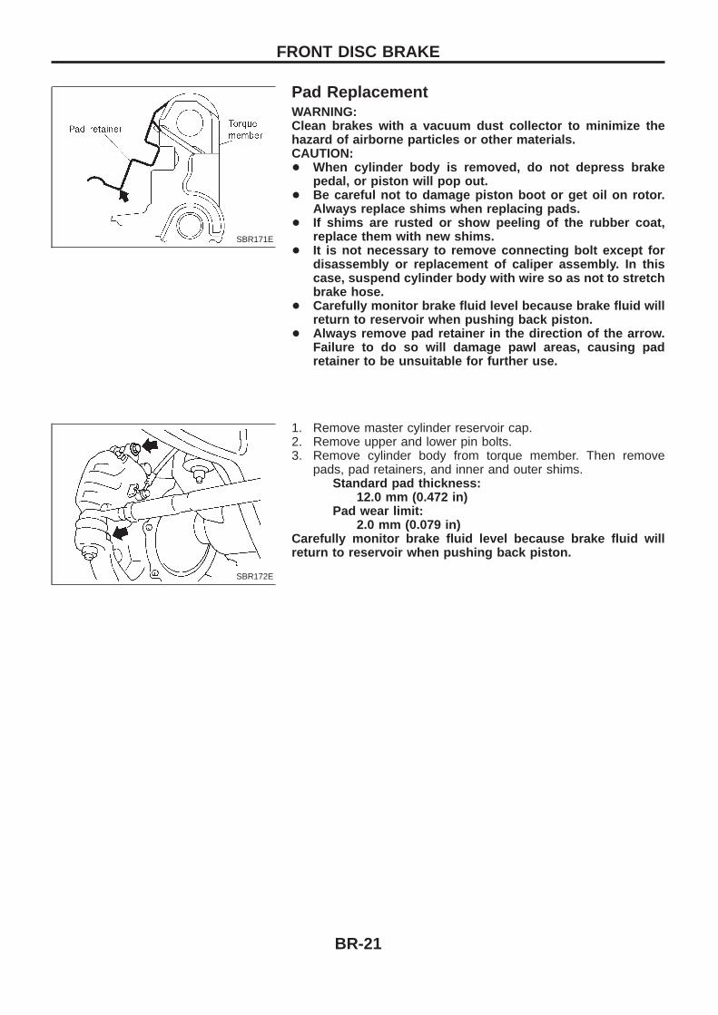
Pad ReplacementWARNING:Clean brakes with a vacuum dust collector to minimize thehazard of airborne particles or other materials.CAUTION:+ When cylinder body is removed, do not depress brake
pedal, or piston will pop out.+ Be careful not to damage piston boot or get oil on rotor.
Always replace shims when replacing pads.+ If shims are rusted or show peeling of the rubber coat,
replace them with new shims.+ It is not necessary to remove connecting bolt except for
disassembly or replacement of caliper assembly. In thiscase, suspend cylinder body with wire so as not to stretchbrake hose.
+ Carefully monitor brake fluid level because brake fluid willreturn to reservoir when pushing back piston.
+ Always remove pad retainer in the direction of the arrow.Failure to do so will damage pawl areas, causing padretainer to be unsuitable for further use.
1. Remove master cylinder reservoir cap.2. Remove upper and lower pin bolts.3. Remove cylinder body from torque member. Then remove
pads, pad retainers, and inner and outer shims.Standard pad thickness:
12.0 mm (0.472 in)Pad wear limit:
2.0 mm (0.079 in)Carefully monitor brake fluid level because brake fluid willreturn to reservoir when pushing back piston.
SBR171E
SBR172E
FRONT DISC BRAKE
BR-21
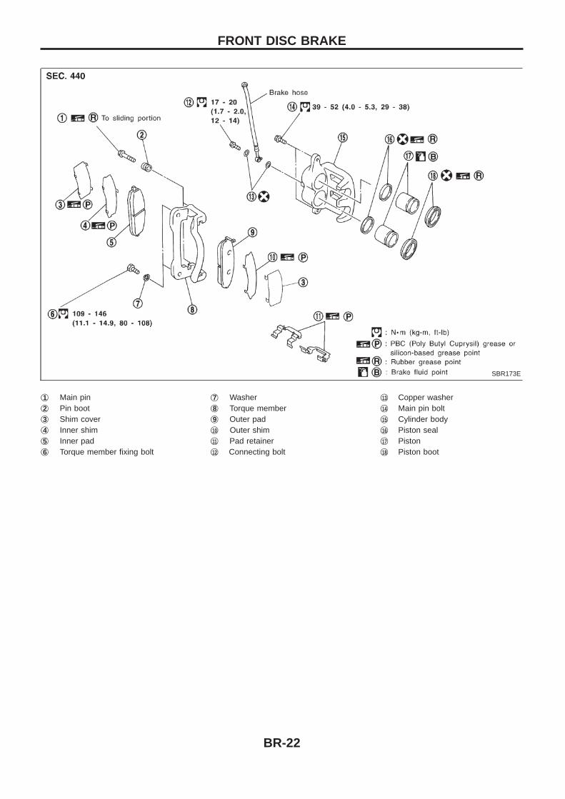
j1 Main pinj2 Pin bootj3 Shim coverj4 Inner shimj5 Inner padj6 Torque member fixing bolt
j7 Washerj8 Torque memberj9 Outer padj10 Outer shimj11 Pad retainerj12 Connecting bolt
j13 Copper washerj14 Main pin boltj15 Cylinder bodyj16 Piston sealj17 Pistonj18 Piston boot
SBR173E
FRONT DISC BRAKE
BR-22
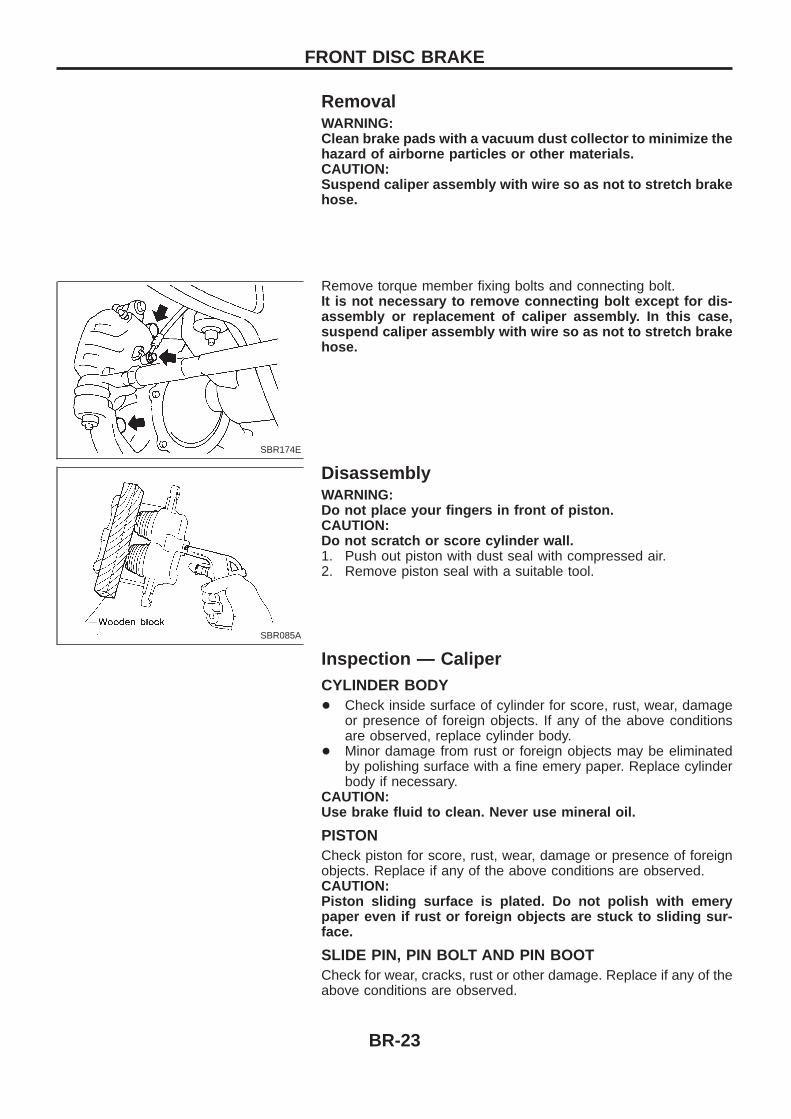
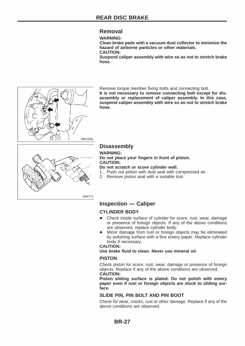
RemovalWARNING:Clean brake pads with a vacuum dust collector to minimize thehazard of airborne particles or other materials.CAUTION:Suspend caliper assembly with wire so as not to stretch brakehose.
Remove torque member fixing bolts and connecting bolt.It is not necessary to remove connecting bolt except for dis-assembly or replacement of caliper assembly. In this case,suspend caliper assembly with wire so as not to stretch brakehose.
DisassemblyWARNING:Do not place your fingers in front of piston.CAUTION:Do not scratch or score cylinder wall.1. Push out piston with dust seal with compressed air.2. Remove piston seal with a suitable tool.
Inspection — CaliperCYLINDER BODY+ Check inside surface of cylinder for score, rust, wear, damage
or presence of foreign objects. If any of the above conditionsare observed, replace cylinder body.
+ Minor damage from rust or foreign objects may be eliminatedby polishing surface with a fine emery paper. Replace cylinderbody if necessary.
CAUTION:Use brake fluid to clean. Never use mineral oil.
PISTONCheck piston for score, rust, wear, damage or presence of foreignobjects. Replace if any of the above conditions are observed.CAUTION:Piston sliding surface is plated. Do not polish with emerypaper even if rust or foreign objects are stuck to sliding sur-face.
SLIDE PIN, PIN BOLT AND PIN BOOTCheck for wear, cracks, rust or other damage. Replace if any of theabove conditions are observed.
SBR174E
SBR085A
FRONT DISC BRAKE
BR-23
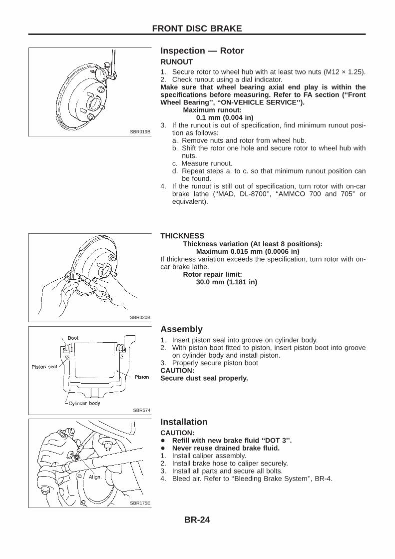
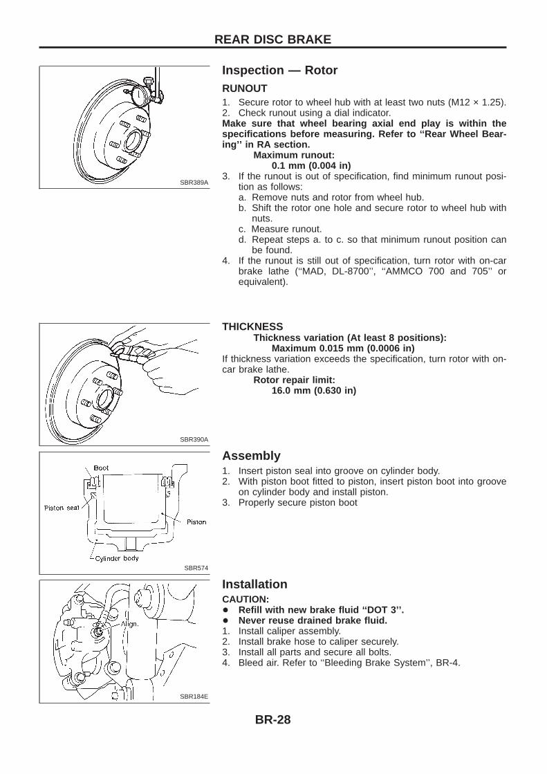
Inspection — RotorRUNOUT1. Secure rotor to wheel hub with at least two nuts (M12 × 1.25).2. Check runout using a dial indicator.Make sure that wheel bearing axial end play is within thespecifications before measuring. Refer to FA section (‘‘FrontWheel Bearing’’, ‘‘ON-VEHICLE SERVICE’’).
Maximum runout:0.1 mm (0.004 in)
3. If the runout is out of specification, find minimum runout posi-tion as follows:a. Remove nuts and rotor from wheel hub.b. Shift the rotor one hole and secure rotor to wheel hub with
nuts.c. Measure runout.d. Repeat steps a. to c. so that minimum runout position can
be found.4. If the runout is still out of specification, turn rotor with on-car
brake lathe (‘‘MAD, DL-8700’’, ‘‘AMMCO 700 and 705’’ orequivalent).
THICKNESSThickness variation (At least 8 positions):
Maximum 0.015 mm (0.0006 in)If thickness variation exceeds the specification, turn rotor with on-car brake lathe.
Rotor repair limit:30.0 mm (1.181 in)
Assembly1. Insert piston seal into groove on cylinder body.2. With piston boot fitted to piston, insert piston boot into groove
on cylinder body and install piston.3. Properly secure piston bootCAUTION:Secure dust seal properly.
InstallationCAUTION:+ Refill with new brake fluid ‘‘DOT 3’’.+ Never reuse drained brake fluid.1. Install caliper assembly.2. Install brake hose to caliper securely.3. Install all parts and secure all bolts.4. Bleed air. Refer to ‘‘Bleeding Brake System’’, BR-4.
SBR019B
SBR020B
SBR574
SBR175E
FRONT DISC BRAKE
BR-24
Pad ReplacementWARNING:Clean brakes with a vacuum dust collector to minimize thehazard of airborne particles or other materials.CAUTION:+ When cylinder body is open, do not depress brake pedal,
or piston will pop out.+ Be careful not to damage piston boot or get oil on rotor.
Always replace shims when replacing pads.+ If shims are rusted or show peeling of the rubber coat,
replace them with new shims.+ It is not necessary to remove connecting bolt except for
disassembly or replacement of caliper assembly. In thiscase, suspend cylinder body with wire so as not to stretchbrake hose.
+ Carefully monitor brake fluid level because brake fluid willreturn to reservoir when pushing back piston.
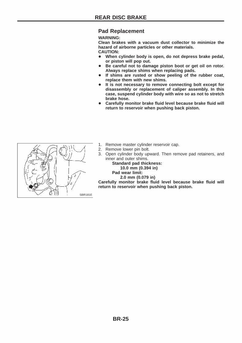
1. Remove master cylinder reservoir cap.2. Remove lower pin bolt.3. Open cylinder body upward. Then remove pad retainers, and
inner and outer shims.Standard pad thickness:
10.0 mm (0.394 in)Pad wear limit:
2.0 mm (0.079 in)Carefully monitor brake fluid level because brake fluid willreturn to reservoir when pushing back piston.
SBR181E
REAR DISC BRAKE
BR-25
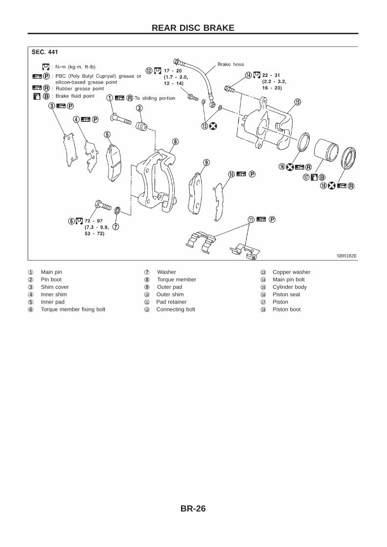
j1 Main pinj2 Pin bootj3 Shim coverj4 Inner shimj5 Inner padj6 Torque member fixing bolt
j7 Washerj8 Torque memberj9 Outer padj10 Outer shimj11 Pad retainerj12 Connecting bolt
j13 Copper washerj14 Main pin boltj15 Cylinder bodyj16 Piston sealj17 Pistonj18 Piston boot
SBR182E
REAR DISC BRAKE
BR-26
RemovalWARNING:Clean brake pads with a vacuum dust collector to minimize thehazard of airborne particles or other materials.CAUTION:Suspend caliper assembly with wire so as not to stretch brakehose.
Remove torque member fixing bolts and connecting bolt.It is not necessary to remove connecting bolt except for dis-assembly or replacement of caliper assembly. In this case,suspend caliper assembly with wire so as not to stretch brakehose.
DisassemblyWARNING:Do not place your fingers in front of piston.CAUTION:Do not scratch or score cylinder wall.1. Push out piston with dust seal with compressed air.2. Remove piston seal with a suitable tool.
Inspection — CaliperCYLINDER BODY+ Check inside surface of cylinder for score, rust, wear, damage
or presence of foreign objects. If any of the above conditionsare observed, replace cylinder body.
+ Minor damage from rust or foreign objects may be eliminatedby polishing surface with a fine emery paper. Replace cylinderbody if necessary.
CAUTION:Use brake fluid to clean. Never use mineral oil.
PISTONCheck piston for score, rust, wear, damage or presence of foreignobjects. Replace if any of the above conditions are observed.CAUTION:Piston sliding surface is plated. Do not polish with emerypaper even if rust or foreign objects are stuck to sliding sur-face.
SLIDE PIN, PIN BOLT AND PIN BOOTCheck for wear, cracks, rust or other damage. Replace if any of theabove conditions are observed.
SBR183E
SBR772
REAR DISC BRAKE
BR-27
Inspection — RotorRUNOUT1. Secure rotor to wheel hub with at least two nuts (M12 × 1.25).2. Check runout using a dial indicator.Make sure that wheel bearing axial end play is within thespecifications before measuring. Refer to ‘‘Rear Wheel Bear-ing’’ in RA section.
Maximum runout:0.1 mm (0.004 in)
3. If the runout is out of specification, find minimum runout posi-tion as follows:a. Remove nuts and rotor from wheel hub.b. Shift the rotor one hole and secure rotor to wheel hub with
nuts.c. Measure runout.d. Repeat steps a. to c. so that minimum runout position can
be found.4. If the runout is still out of specification, turn rotor with on-car
brake lathe (‘‘MAD, DL-8700’’, ‘‘AMMCO 700 and 705’’ orequivalent).
THICKNESSThickness variation (At least 8 positions):
Maximum 0.015 mm (0.0006 in)If thickness variation exceeds the specification, turn rotor with on-car brake lathe.
Rotor repair limit:16.0 mm (0.630 in)
Assembly1. Insert piston seal into groove on cylinder body.2. With piston boot fitted to piston, insert piston boot into groove
on cylinder body and install piston.3. Properly secure piston boot
InstallationCAUTION:+ Refill with new brake fluid ‘‘DOT 3’’.+ Never reuse drained brake fluid.1. Install caliper assembly.2. Install brake hose to caliper securely.3. Install all parts and secure all bolts.4. Bleed air. Refer to ‘‘Bleeding Brake System’’, BR-4.
SBR389A
SBR390A
SBR574
SBR184E
REAR DISC BRAKE
BR-28
Removal1. Disconnect harness connector.2. Disconnect control cable from control lever and bracket.3. Remove control lever and bracket.4. Disconnect control cable from center brake and remove control
cable.
Inspection1. Check control lever and ratchet for evidence of wear or other
damage. Replace if necessary.2. Check wires for evidence of discontinuity or other deterioration.
Replace if necessary.3. Check parts at each connection for deformation or damage.
Replace if necessary.4. Check warning lamp and switch. Replace if necessary.
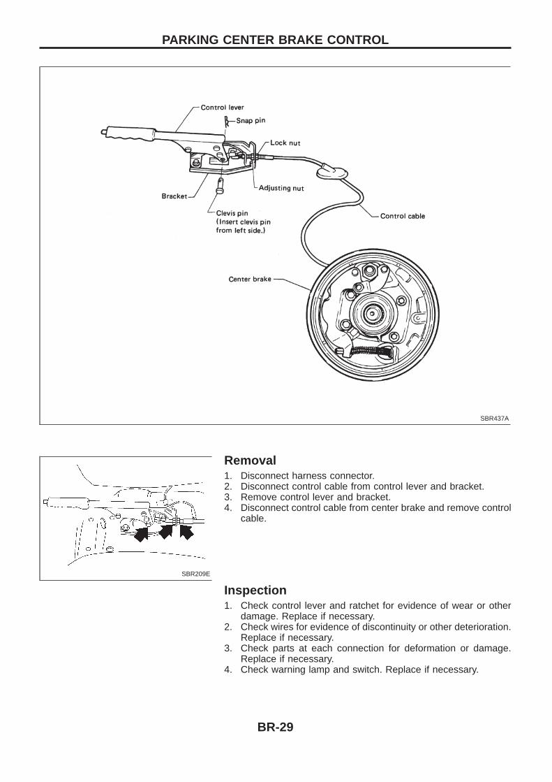
SBR437A
SBR209E
PARKING CENTER BRAKE CONTROL
BR-29
Installation1. Apply a coating of grease to sliding contact surfaces.2. Insert clevis pin from left side.3. After installation is completed, adjust entire system.
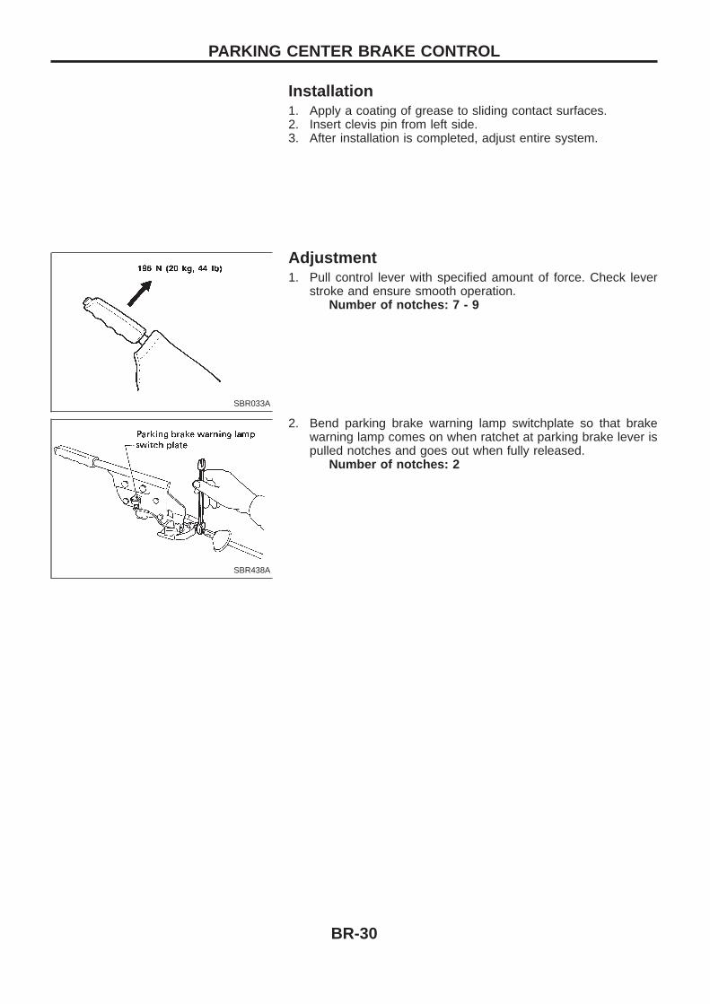
Adjustment1. Pull control lever with specified amount of force. Check lever
stroke and ensure smooth operation.Number of notches : 7 - 9
2. Bend parking brake warning lamp switchplate so that brakewarning lamp comes on when ratchet at parking brake lever ispulled notches and goes out when fully released.
Number of notches: 2
SBR033A
SBR438A
PARKING CENTER BRAKE CONTROL
BR-30
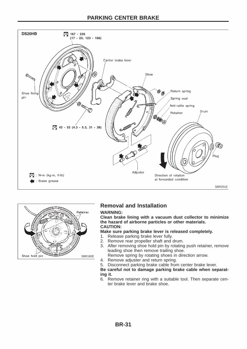
Removal and InstallationWARNING:Clean brake lining with a vacuum dust collector to minimizethe hazard of airborne particles or other materials.CAUTION:Make sure parking brake lever is released completely.1. Release parking brake lever fully.2. Remove rear propeller shaft and drum.3. After removing shoe hold pin by rotating push retainer, remove
leading shoe then remove trailing shoe.Remove spring by rotating shoes in direction arrow.
4. Remove adjuster and return spring.5. Disconnect parking brake cable from center brake lever.Be careful not to damage parking brake cable when separat-ing it.6. Remove retainer ring with a suitable tool. Then separate cen-
ter brake lever and brake shoe.
SBR251E
SBR180E
PARKING CENTER BRAKE
BR-31
When installing, measure brake drum inside diameter and diameterof brake shoes. Check that the difference between diameters is thecorrect shoe clearance.
Shoe clearance:0.25 - 0.4 mm (0.0098 - 0.0157 in)
If necessary, adjust by rotating adjuster.
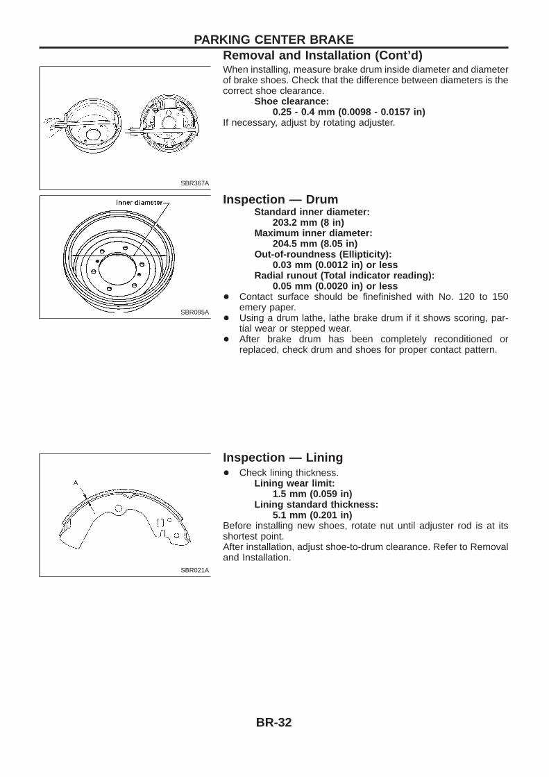
Inspection — DrumStandard inner diameter:
203.2 mm (8 in)Maximum inner diameter:
204.5 mm (8.05 in)Out-of-roundness (Ellipticity):
0.03 mm (0.0012 in) or lessRadial runout (Total indicator reading):
0.05 mm (0.0020 in) or less+ Contact surface should be finefinished with No. 120 to 150
emery paper.+ Using a drum lathe, lathe brake drum if it shows scoring, par-
tial wear or stepped wear.+ After brake drum has been completely reconditioned or
replaced, check drum and shoes for proper contact pattern.
Inspection — Lining+ Check lining thickness.
Lining wear limit:1.5 mm (0.059 in)
Lining standard thickness:5.1 mm (0.201 in)
Before installing new shoes, rotate nut until adjuster rod is at itsshortest point.After installation, adjust shoe-to-drum clearance. Refer to Removaland Installation.
SBR367A
SBR095A
SBR021A
PARKING CENTER BRAKERemoval and Installation (Cont’d)
BR-32
PurposeThe Anti-Lock Brake System (ABS) consists of electronic and hydraulic components. It allows for control ofbraking force so locking of the wheels can be avoided.The ABS:1) Improves proper tracking performance through steering wheel operation.2) Eases obstacle avoidance through steering wheel operation.3) Improves vehicle stability.
Operation+ When the vehicle speed is less than 10 km/h (6 MPH) this system does not work.+ The Anti-Lock Brake System (ABS) has a self-test function. The system turns on the ABS warning lamp
for 1 second each time the ignition switch is turned ‘‘ON’’. After the engine is started, the ABS warninglamp turns off. The system performs a test the first time the vehicle reaches 6 km/h (4 MPH). A mechani-cal noise may be heard as the ABS performs this self-test. This is a normal part of the self-test feature. Ifa malfunction is found during this check, the ABS warning lamp will stay on.
+ While driving, a mechanical noise may be heard during ABS operation. This is a normal condition.+ While DIFF-LOCK is on, the anti-lock brake warning light flashes. This indicates that anti-lock may not be
fully operated. (ABS only)
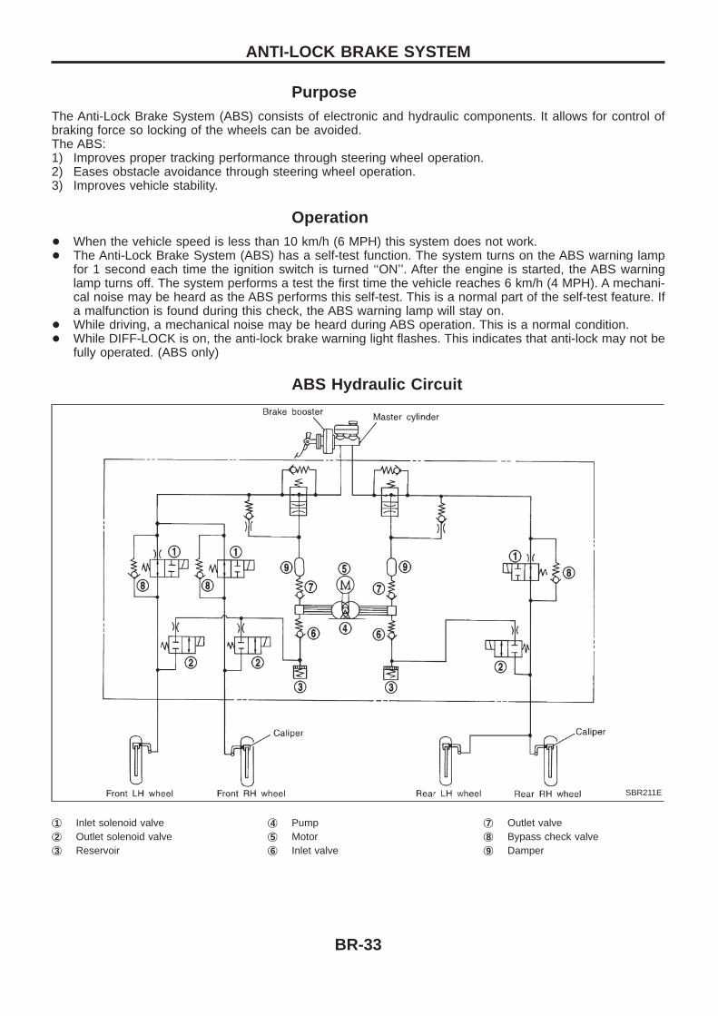
ABS Hydraulic Circuit
j1 Inlet solenoid valvej2 Outlet solenoid valvej3 Reservoir
j4 Pumpj5 Motorj6 Inlet valve
j7 Outlet valvej8 Bypass check valvej9 Damper
SBR211E
ANTI-LOCK BRAKE SYSTEM
BR-33
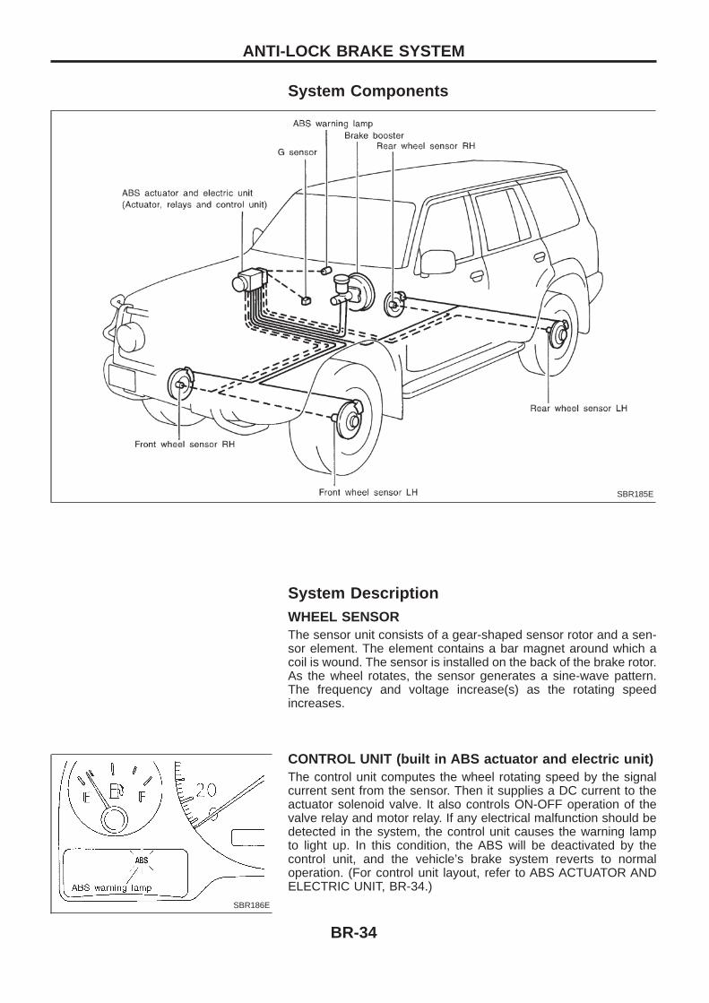
System Components
System DescriptionWHEEL SENSORThe sensor unit consists of a gear-shaped sensor rotor and a sen-sor element. The element contains a bar magnet around which acoil is wound. The sensor is installed on the back of the brake rotor.As the wheel rotates, the sensor generates a sine-wave pattern.The frequency and voltage increase(s) as the rotating speedincreases.
CONTROL UNIT (built in ABS actuator and electric unit)The control unit computes the wheel rotating speed by the signalcurrent sent from the sensor. Then it supplies a DC current to theactuator solenoid valve. It also controls ON-OFF operation of thevalve relay and motor relay. If any electrical malfunction should bedetected in the system, the control unit causes the warning lampto light up. In this condition, the ABS will be deactivated by thecontrol unit, and the vehicle’s brake system reverts to normaloperation. (For control unit layout, refer to ABS ACTUATOR ANDELECTRIC UNIT, BR-34.)
SBR185E
SBR186E
ANTI-LOCK BRAKE SYSTEM
BR-34
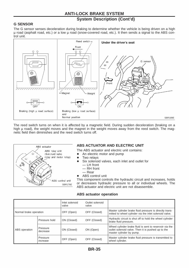
G SENSORThe G sensor senses deceleration during braking to determine whether the vehicle is being driven on a highµ road (asphalt road, etc.) or a low µ road (snow-covered road, etc.). It then sends a signal to the ABS con-trol unit.
The reed switch turns on when it is affected by a magnetic field. During sudden deceleration (braking on ahigh µ road), the weight moves and the magnet in the weight moves away from the reed switch. The mag-netic field then diminishes and the reed switch turns off.
ABS ACTUATOR AND ELECTRIC UNITThe ABS actuator and electric unit contains:+ An electric motor and pump+ Two relays+ Six solenoid valves, each inlet and outlet for
— LH front— RH front— Rear
+ ABS control unitThis component controls the hydraulic circuit and increases, holdsor decreases hydraulic pressure to all or individual wheels. TheABS actuator and electric unit are not disassemble.
ABS actuator operation
Inlet solenoidvalve
Outlet solenoidvalve
Normal brake operation OFF (Open) OFF (Closed) Master cylinder brake fluid pressure is directly trans-mitted to wheel cylinder via the inlet solenoid valve.
ABS operation
Pressure hold ON (Closed) OFF (Closed) Hydraulic circuit is shut off to hold the wheel cylinderbrake fluid pressure.
Pressuredecrease ON (Closed) ON (Open)
Wheel cylinder brake fluid is sent to reservoir via theoutlet solenoid valve. Then it is pushed up to themaster cylinder by pump.
Pressureincrease OFF (Open) OFF (Closed) Master cylinder brake fluid pressure is transmitted to
wheel cylinder.
SBR189E
SBR176E
ANTI-LOCK BRAKE SYSTEMSystem Description (Cont’d)
BR-35
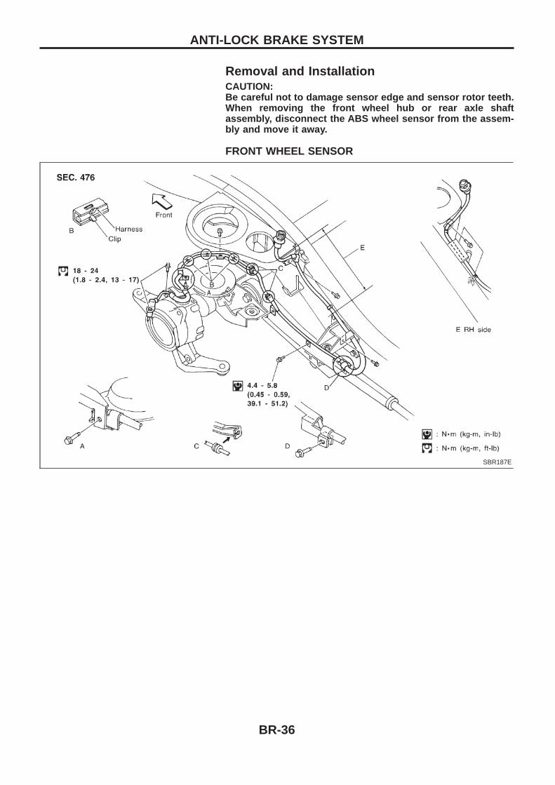
Removal and InstallationCAUTION:Be careful not to damage sensor edge and sensor rotor teeth.When removing the front wheel hub or rear axle shaftassembly, disconnect the ABS wheel sensor from the assem-bly and move it away.
FRONT WHEEL SENSOR
SBR187E
ANTI-LOCK BRAKE SYSTEM
BR-36
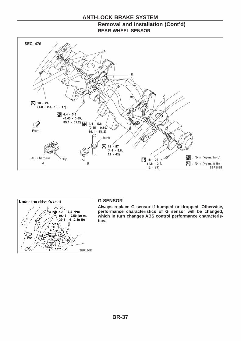
REAR WHEEL SENSOR
G SENSORAlways replace G sensor if bumped or dropped. Otherwise,performance characteristics of G sensor will be changed,which in turn changes ABS control performance characteris-tics.
SBR188E
SBR190E
ANTI-LOCK BRAKE SYSTEMRemoval and Installation (Cont’d)
BR-37
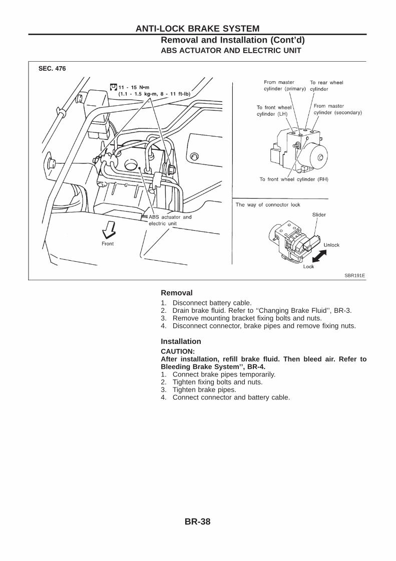
ABS ACTUATOR AND ELECTRIC UNIT
Removal1. Disconnect battery cable.2. Drain brake fluid. Refer to ‘‘Changing Brake Fluid’’, BR-3.3. Remove mounting bracket fixing bolts and nuts.4. Disconnect connector, brake pipes and remove fixing nuts.
InstallationCAUTION:After installation, refill brake fluid. Then bleed air. Refer toBleeding Brake System’’, BR-4.1. Connect brake pipes temporarily.2. Tighten fixing bolts and nuts.3. Tighten brake pipes.4. Connect connector and battery cable.
SBR191E
ANTI-LOCK BRAKE SYSTEMRemoval and Installation (Cont’d)
BR-38
How to Perform Trouble Diagnoses for Quickand Accurate RepairINTRODUCTIONThe ABS system has an electronic control unit to control majorfunctions. The control unit accepts input signals from sensors andinstantly drives the actuators. It is essential that both kinds of sig-nals are proper and stable. It is also important to check for conven-tional problems: such as air leaks in booster lines, lack of brakefluid, or other problems with the brake system.It is much more difficult to diagnose a problem that occurs intermit-tently rather than continuously. Most intermittent problems arecaused by poor electric connections or faulty wiring. In this case,careful checking of suspicious circuits may help prevent thereplacement of good parts.A visual check only may not find the cause of the problems, so aroad test should be performed.Before undertaking actual checks, take a few minutes to talk witha customer who approaches with a ABS complaint. The customeris a very good source of information on such problems; especiallyintermittent ones. Through the talks with the customer, find out whatsymptoms are present and under what conditions they occur.Start your diagnosis by looking for ‘‘conventional’’ problems first.This is one of the best ways to troubleshoot brake problems on anABS controlled vehicle.
SEF233G
SEF234G
TROUBLE DIAGNOSES
BR-39
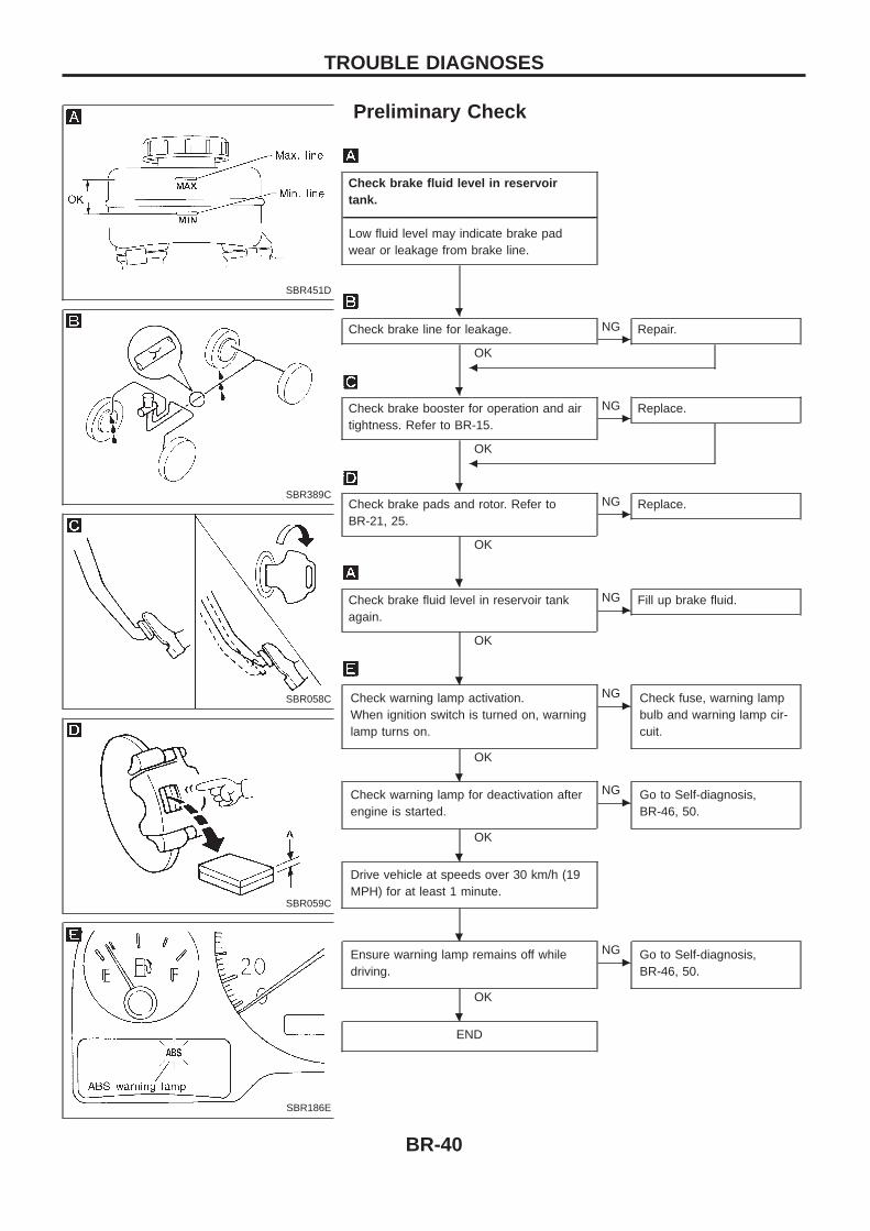
Preliminary Check
Check brake fluid level in reservoirtank.
----------------------------------------------------------------------------------------------------------------------------------------------------------------------------------------------------------------------------------------------------------------------------------------------------------------Low fluid level may indicate brake padwear or leakage from brake line.
Check brake line for leakage.
OKc
NG Repair.
b
Check brake booster for operation and airtightness. Refer to BR-15.
OK
cNG Replace.
b
Check brake pads and rotor. Refer toBR-21, 25.
OK
cNG Replace.
Check brake fluid level in reservoir tankagain.
OK
cNG Fill up brake fluid.
Check warning lamp activation.When ignition switch is turned on, warninglamp turns on.
OK
cNG Check fuse, warning lamp
bulb and warning lamp cir-cuit.
Check warning lamp for deactivation afterengine is started.
OK
cNG Go to Self-diagnosis,
BR-46, 50.
Drive vehicle at speeds over 30 km/h (19MPH) for at least 1 minute.
Ensure warning lamp remains off whiledriving.
OK
cNG Go to Self-diagnosis,
BR-46, 50.
END
SBR451D
SBR389C
SBR058C
SBR059C
SBR186E
.
.
.
.
.
.
.
.
.
TROUBLE DIAGNOSES
BR-40
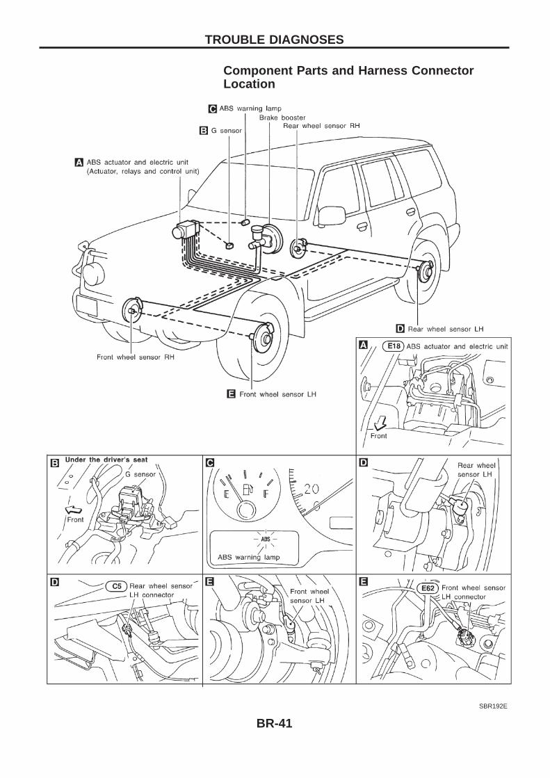
Component Parts and Harness ConnectorLocation
SBR192E
TROUBLE DIAGNOSES
BR-41
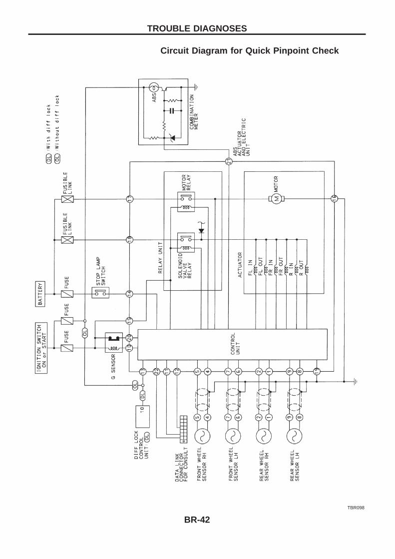
Circuit Diagram for Quick Pinpoint Check
TBR098
TROUBLE DIAGNOSES
BR-42
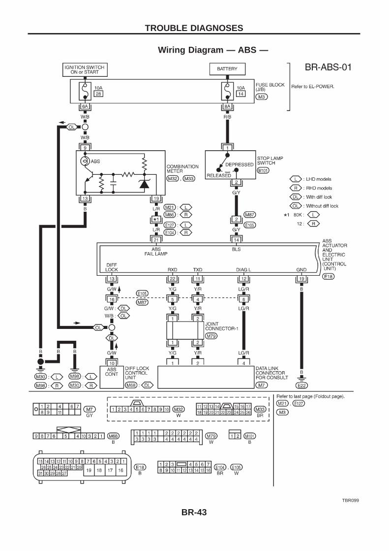
Wiring Diagram — ABS —
TBR099
TROUBLE DIAGNOSES
BR-43
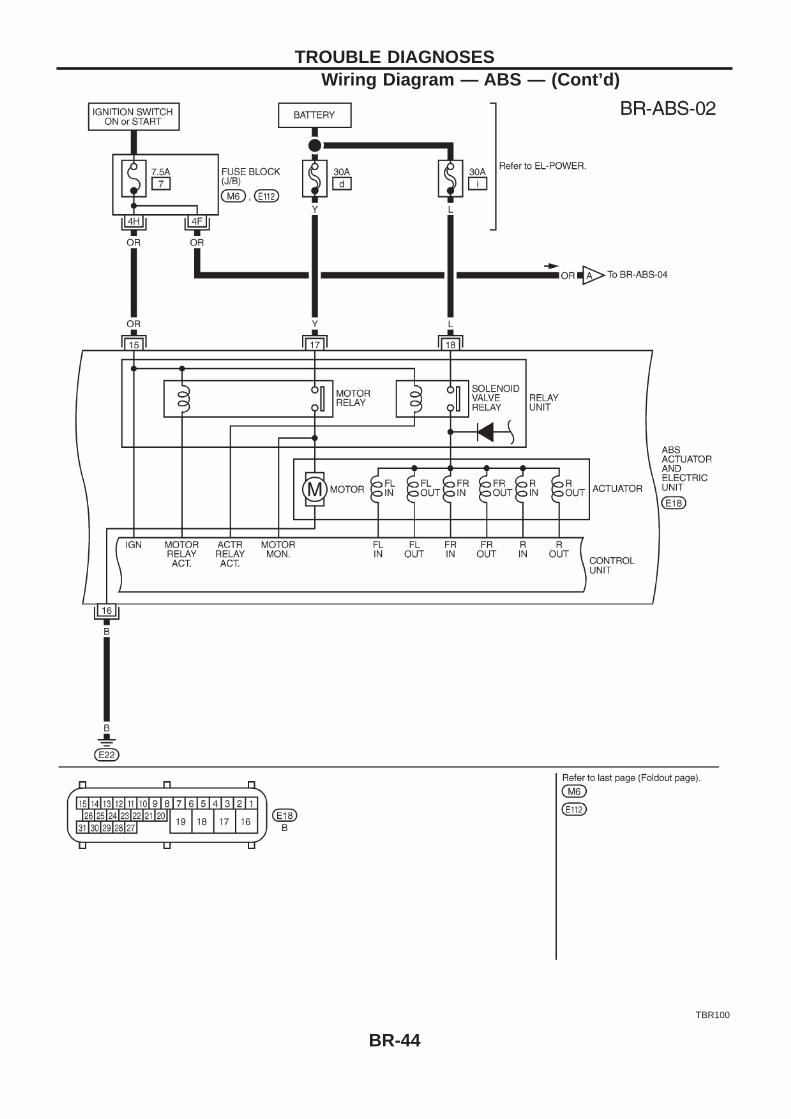
TBR100
TROUBLE DIAGNOSESWiring Diagram — ABS — (Cont’d)
BR-44
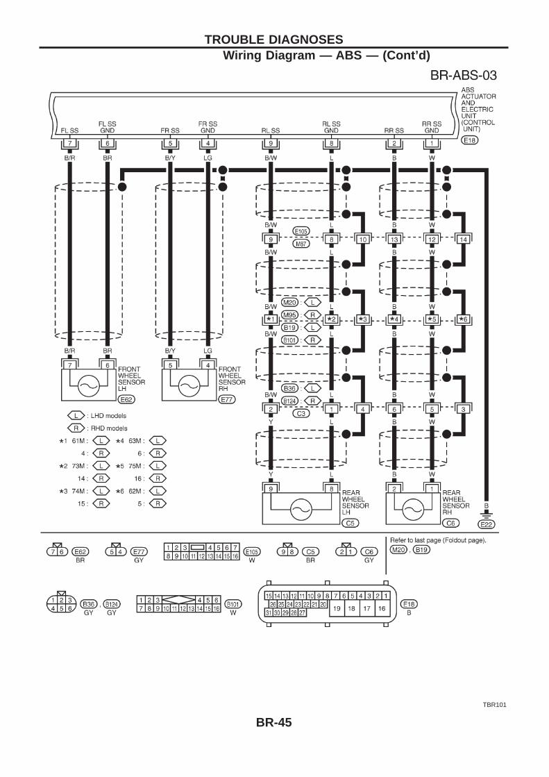
TBR101
TROUBLE DIAGNOSESWiring Diagram — ABS — (Cont’d)
BR-45
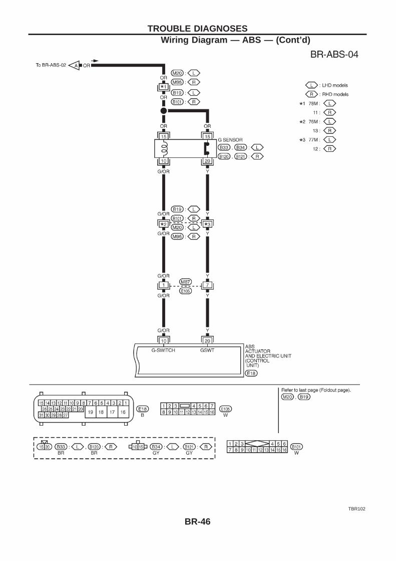
TBR102
TROUBLE DIAGNOSESWiring Diagram — ABS — (Cont’d)
BR-46
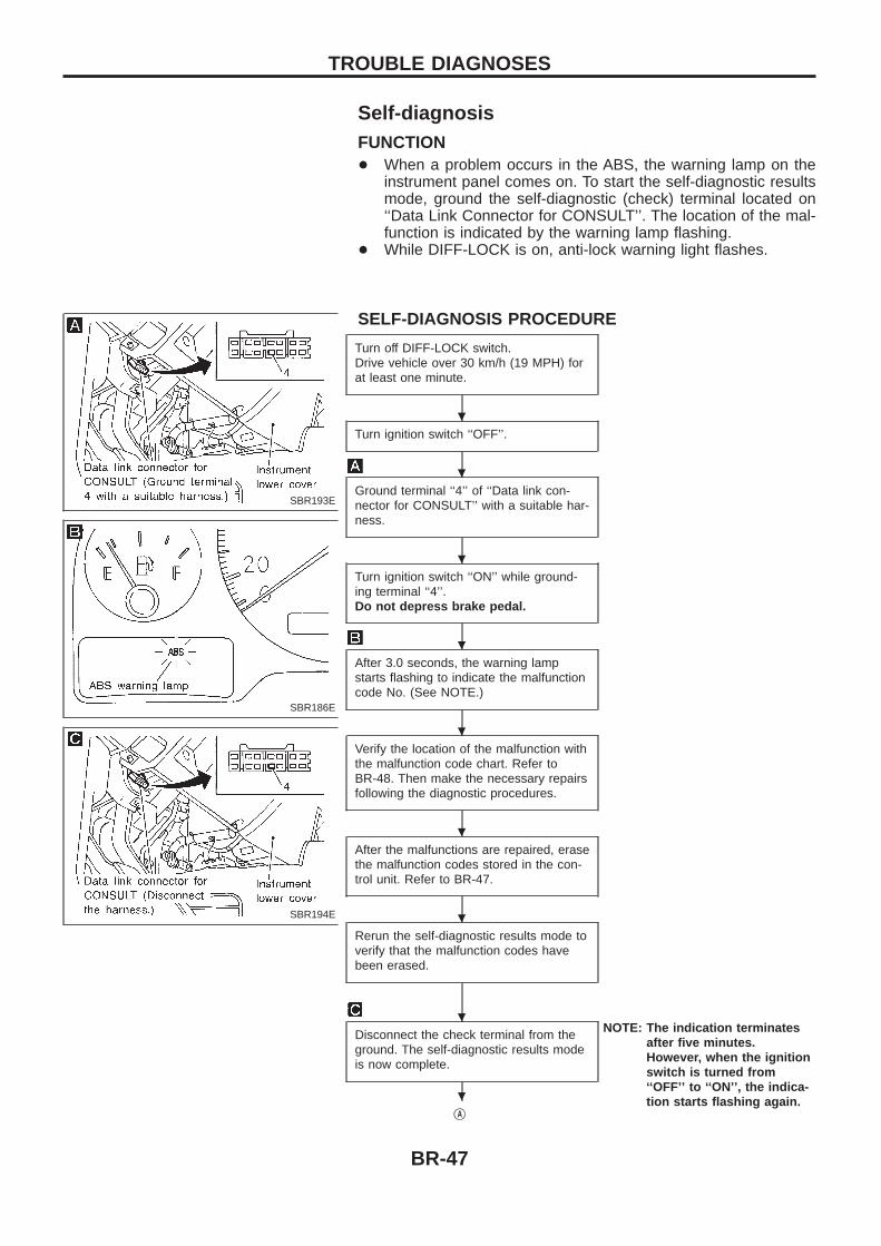
Self-diagnosisFUNCTION+ When a problem occurs in the ABS, the warning lamp on the
instrument panel comes on. To start the self-diagnostic resultsmode, ground the self-diagnostic (check) terminal located on‘‘Data Link Connector for CONSULT’’. The location of the mal-function is indicated by the warning lamp flashing.
+ While DIFF-LOCK is on, anti-lock warning light flashes.
SELF-DIAGNOSIS PROCEDURE
Turn off DIFF-LOCK switch.Drive vehicle over 30 km/h (19 MPH) forat least one minute.
Turn ignition switch ‘‘OFF’’.
Ground terminal ‘‘4’’ of ‘‘Data link con-nector for CONSULT’’ with a suitable har-ness.
Turn ignition switch ‘‘ON’’ while ground-ing terminal ‘‘4’’.Do not depress brake pedal.
After 3.0 seconds, the warning lampstarts flashing to indicate the malfunctioncode No. (See NOTE.)
Verify the location of the malfunction withthe malfunction code chart. Refer toBR-48. Then make the necessary repairsfollowing the diagnostic procedures.
After the malfunctions are repaired, erasethe malfunction codes stored in the con-trol unit. Refer to BR-47.
Rerun the self-diagnostic results mode toverify that the malfunction codes havebeen erased.
Disconnect the check terminal from theground. The self-diagnostic results modeis now complete.
NOTE: The indication terminatesafter five minutes.However, when the ignitionswitch is turned from‘‘OFF’’ to ‘‘ON’’, the indica-tion starts flashing again.
jA
SBR193E
SBR186E
SBR194E
.
.
.
.
.
.
.
.
.
TROUBLE DIAGNOSES
BR-47
jA
Check warning lamp for deactivation afterdriving vehicle over 30 km/h (19 MPH)for at least one minute.
After making certain that warning lampdoes not come on, test the ABS in a safearea to verify that it functions properly.
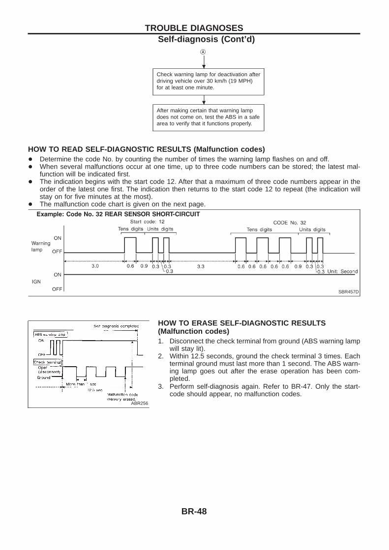
HOW TO READ SELF-DIAGNOSTIC RESULTS (Malfunction codes)+ Determine the code No. by counting the number of times the warning lamp flashes on and off.+ When several malfunctions occur at one time, up to three code numbers can be stored; the latest mal-
function will be indicated first.+ The indication begins with the start code 12. After that a maximum of three code numbers appear in the
order of the latest one first. The indication then returns to the start code 12 to repeat (the indication willstay on for five minutes at the most).
+ The malfunction code chart is given on the next page.
HOW TO ERASE SELF-DIAGNOSTIC RESULTS(Malfunction codes)1. Disconnect the check terminal from ground (ABS warning lamp
will stay lit).2. Within 12.5 seconds, ground the check terminal 3 times. Each
terminal ground must last more than 1 second. The ABS warn-ing lamp goes out after the erase operation has been com-pleted.
3. Perform self-diagnosis again. Refer to BR-47. Only the start-code should appear, no malfunction codes.
SBR457D
ABR256
.
.
TROUBLE DIAGNOSESSelf-diagnosis (Cont’d)
BR-48
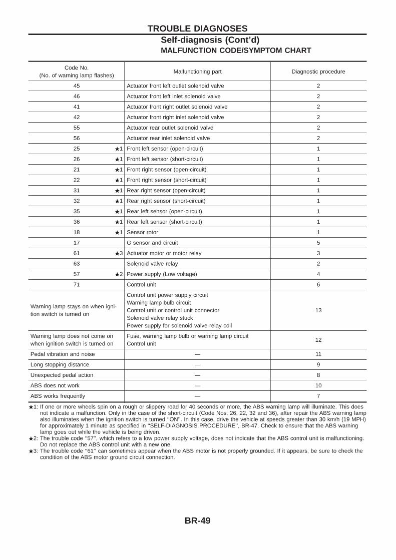
MALFUNCTION CODE/SYMPTOM CHART
Code No.(No. of warning lamp flashes)
Malfunctioning part Diagnostic procedure
45 Actuator front left outlet solenoid valve 2
46 Actuator front left inlet solenoid valve 2
41 Actuator front right outlet solenoid valve 2
42 Actuator front right inlet solenoid valve 2
55 Actuator rear outlet solenoid valve 2
56 Actuator rear inlet solenoid valve 2
25 .1 Front left sensor (open-circuit) 1
26 .1 Front left sensor (short-circuit) 1
21 .1 Front right sensor (open-circuit) 1
22 .1 Front right sensor (short-circuit) 1
31 .1 Rear right sensor (open-circuit) 1
32 .1 Rear right sensor (short-circuit) 1
35 .1 Rear left sensor (open-circuit) 1
36 .1 Rear left sensor (short-circuit) 1
18 .1 Sensor rotor 1
17 G sensor and circuit 5
61 .3 Actuator motor or motor relay 3
63 Solenoid valve relay 2
57 .2 Power supply (Low voltage) 4
71 Control unit 6
Warning lamp stays on when igni-tion switch is turned on
Control unit power supply circuitWarning lamp bulb circuitControl unit or control unit connectorSolenoid valve relay stuckPower supply for solenoid valve relay coil
13
Warning lamp does not come onwhen ignition switch is turned on
Fuse, warning lamp bulb or warning lamp circuitControl unit
12
Pedal vibration and noise — 11
Long stopping distance — 9
Unexpected pedal action — 8
ABS does not work — 10
ABS works frequently — 7
.1: If one or more wheels spin on a rough or slippery road for 40 seconds or more, the ABS warning lamp will illuminate. This doesnot indicate a malfunction. Only in the case of the short-circuit (Code Nos. 26, 22, 32 and 36), after repair the ABS warning lampalso illuminates when the ignition switch is turned ‘‘ON’’. In this case, drive the vehicle at speeds greater than 30 km/h (19 MPH)for approximately 1 minute as specified in ‘‘SELF-DIAGNOSIS PROCEDURE’’, BR-47. Check to ensure that the ABS warninglamp goes out while the vehicle is being driven.
.2: The trouble code ‘‘57’’, which refers to a low power supply voltage, does not indicate that the ABS control unit is malfunctioning.Do not replace the ABS control unit with a new one.
.3: The trouble code ‘‘61’’ can sometimes appear when the ABS motor is not properly grounded. If it appears, be sure to check thecondition of the ABS motor ground circuit connection.
TROUBLE DIAGNOSESSelf-diagnosis (Cont’d)
BR-49
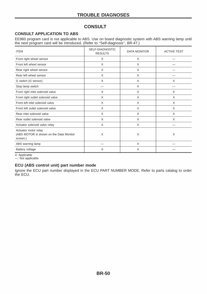
CONSULTCONSULT APPLICATION TO ABSEE960 program card is not applicable to ABS. Use on board diagnostic system with ABS warning lamp untilthe next program card will be introduced. (Refer to ‘‘Self-diagnosis’’, BR-47.)
ITEMSELF-DIAGNOSTIC
RESULTSDATA MONITOR ACTIVE TEST
Front right wheel sensor X X —
Front left wheel sensor X X —
Rear right wheel sensor X X —
Rear left wheel sensor X X —
G switch (G sensor) X X X
Stop lamp switch — X —
Front right inlet solenoid valve X X X
Front right outlet solenoid valve X X X
Front left inlet solenoid valve X X X
Front left outlet solenoid valve X X X
Rear inlet solenoid valve X X X
Rear outlet solenoid valve X X X
Actuator solenoid valve relay X X —
Actuator motor relay(ABS MOTOR is shown on the Data Monitorscreen.)
X X X
ABS warning lamp — X —
Battery voltage X X —
X: Applicable—: Not applicable
ECU (ABS control unit) part number modeIgnore the ECU part number displayed in the ECU PART NUMBER MODE. Refer to parts catalog to orderthe ECU.
TROUBLE DIAGNOSES
BR-50
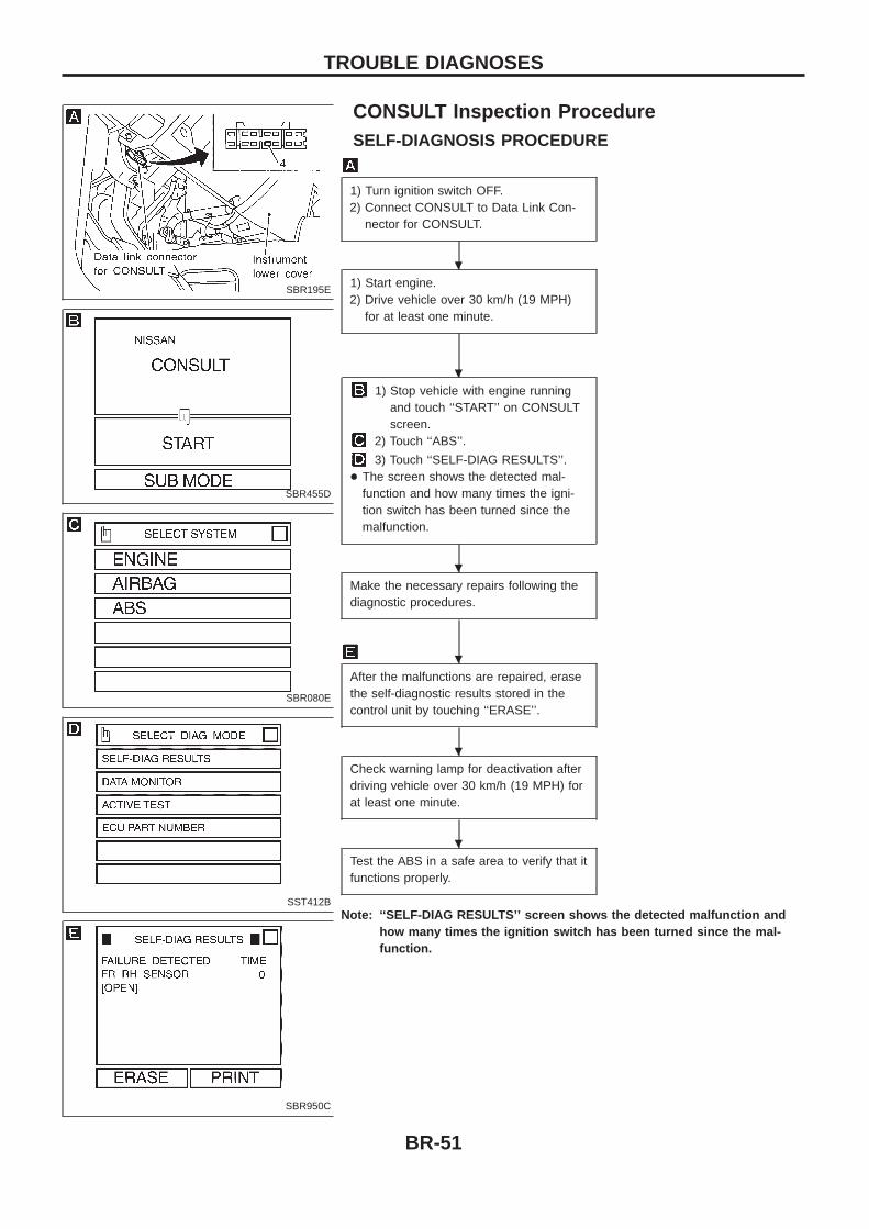
CONSULT Inspection ProcedureSELF-DIAGNOSIS PROCEDURE
1) Turn ignition switch OFF.2) Connect CONSULT to Data Link Con-
nector for CONSULT.
1) Start engine.2) Drive vehicle over 30 km/h (19 MPH)
for at least one minute.
1) Stop vehicle with engine runningand touch ‘‘START’’ on CONSULTscreen.
2) Touch ‘‘ABS’’.
3) Touch ‘‘SELF-DIAG RESULTS’’.+ The screen shows the detected mal-
function and how many times the igni-tion switch has been turned since themalfunction.
Make the necessary repairs following thediagnostic procedures.
After the malfunctions are repaired, erasethe self-diagnostic results stored in thecontrol unit by touching ‘‘ERASE’’.
Check warning lamp for deactivation afterdriving vehicle over 30 km/h (19 MPH) forat least one minute.
Test the ABS in a safe area to verify that itfunctions properly.
Note: ‘‘SELF-DIAG RESULTS’’ screen shows the detected malfunction andhow many times the ignition switch has been turned since the mal-function.
SBR195E
SBR455D
SBR080E
SST412B
SBR950C
.
.
.
.
.
.
TROUBLE DIAGNOSES
BR-51
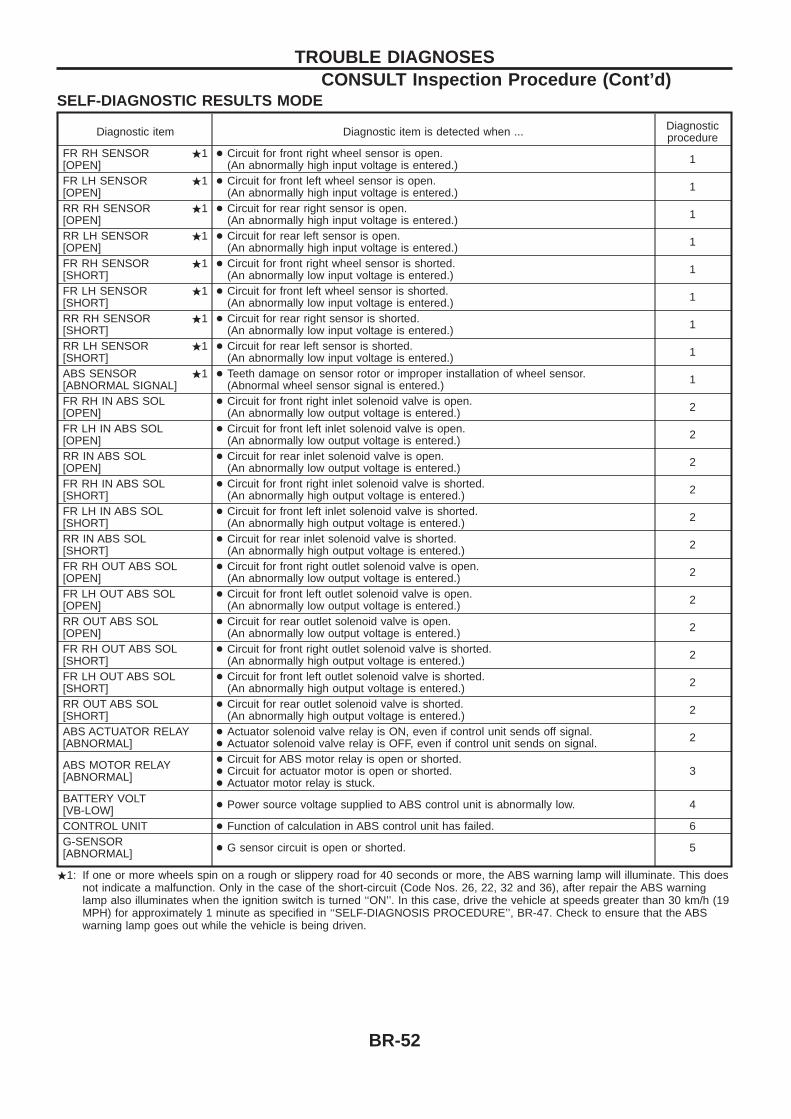
SELF-DIAGNOSTIC RESULTS MODE
Diagnostic item Diagnostic item is detected when ... Diagnosticprocedure
FR RH SENSOR .1[OPEN]
+ Circuit for front right wheel sensor is open.(An abnormally high input voltage is entered.) 1
FR LH SENSOR .1[OPEN]
+ Circuit for front left wheel sensor is open.(An abnormally high input voltage is entered.) 1
RR RH SENSOR .1[OPEN]
+ Circuit for rear right sensor is open.(An abnormally high input voltage is entered.) 1
RR LH SENSOR .1[OPEN]
+ Circuit for rear left sensor is open.(An abnormally high input voltage is entered.) 1
FR RH SENSOR .1[SHORT]
+ Circuit for front right wheel sensor is shorted.(An abnormally low input voltage is entered.) 1
FR LH SENSOR .1[SHORT]
+ Circuit for front left wheel sensor is shorted.(An abnormally low input voltage is entered.) 1
RR RH SENSOR .1[SHORT]
+ Circuit for rear right sensor is shorted.(An abnormally low input voltage is entered.) 1
RR LH SENSOR .1[SHORT]
+ Circuit for rear left sensor is shorted.(An abnormally low input voltage is entered.) 1
ABS SENSOR .1[ABNORMAL SIGNAL]
+ Teeth damage on sensor rotor or improper installation of wheel sensor.(Abnormal wheel sensor signal is entered.) 1
FR RH IN ABS SOL[OPEN]
+ Circuit for front right inlet solenoid valve is open.(An abnormally low output voltage is entered.) 2
FR LH IN ABS SOL[OPEN]
+ Circuit for front left inlet solenoid valve is open.(An abnormally low output voltage is entered.) 2
RR IN ABS SOL[OPEN]
+ Circuit for rear inlet solenoid valve is open.(An abnormally low output voltage is entered.) 2
FR RH IN ABS SOL[SHORT]
+ Circuit for front right inlet solenoid valve is shorted.(An abnormally high output voltage is entered.) 2
FR LH IN ABS SOL[SHORT]
+ Circuit for front left inlet solenoid valve is shorted.(An abnormally high output voltage is entered.) 2
RR IN ABS SOL[SHORT]
+ Circuit for rear inlet solenoid valve is shorted.(An abnormally high output voltage is entered.) 2
FR RH OUT ABS SOL[OPEN]
+ Circuit for front right outlet solenoid valve is open.(An abnormally low output voltage is entered.) 2
FR LH OUT ABS SOL[OPEN]
+ Circuit for front left outlet solenoid valve is open.(An abnormally low output voltage is entered.) 2
RR OUT ABS SOL[OPEN]
+ Circuit for rear outlet solenoid valve is open.(An abnormally low output voltage is entered.) 2
FR RH OUT ABS SOL[SHORT]
+ Circuit for front right outlet solenoid valve is shorted.(An abnormally high output voltage is entered.) 2
FR LH OUT ABS SOL[SHORT]
+ Circuit for front left outlet solenoid valve is shorted.(An abnormally high output voltage is entered.) 2
RR OUT ABS SOL[SHORT]
+ Circuit for rear outlet solenoid valve is shorted.(An abnormally high output voltage is entered.) 2
ABS ACTUATOR RELAY[ABNORMAL]
+ Actuator solenoid valve relay is ON, even if control unit sends off signal.+ Actuator solenoid valve relay is OFF, even if control unit sends on signal. 2
ABS MOTOR RELAY[ABNORMAL]
+ Circuit for ABS motor relay is open or shorted.+ Circuit for actuator motor is open or shorted.+ Actuator motor relay is stuck.
3
BATTERY VOLT[VB-LOW] + Power source voltage supplied to ABS control unit is abnormally low. 4
CONTROL UNIT + Function of calculation in ABS control unit has failed. 6G-SENSOR[ABNORMAL] + G sensor circuit is open or shorted. 5
.1: If one or more wheels spin on a rough or slippery road for 40 seconds or more, the ABS warning lamp will illuminate. This doesnot indicate a malfunction. Only in the case of the short-circuit (Code Nos. 26, 22, 32 and 36), after repair the ABS warninglamp also illuminates when the ignition switch is turned ‘‘ON’’. In this case, drive the vehicle at speeds greater than 30 km/h (19MPH) for approximately 1 minute as specified in ‘‘SELF-DIAGNOSIS PROCEDURE’’, BR-47. Check to ensure that the ABSwarning lamp goes out while the vehicle is being driven.
TROUBLE DIAGNOSESCONSULT Inspection Procedure (Cont’d)
BR-52
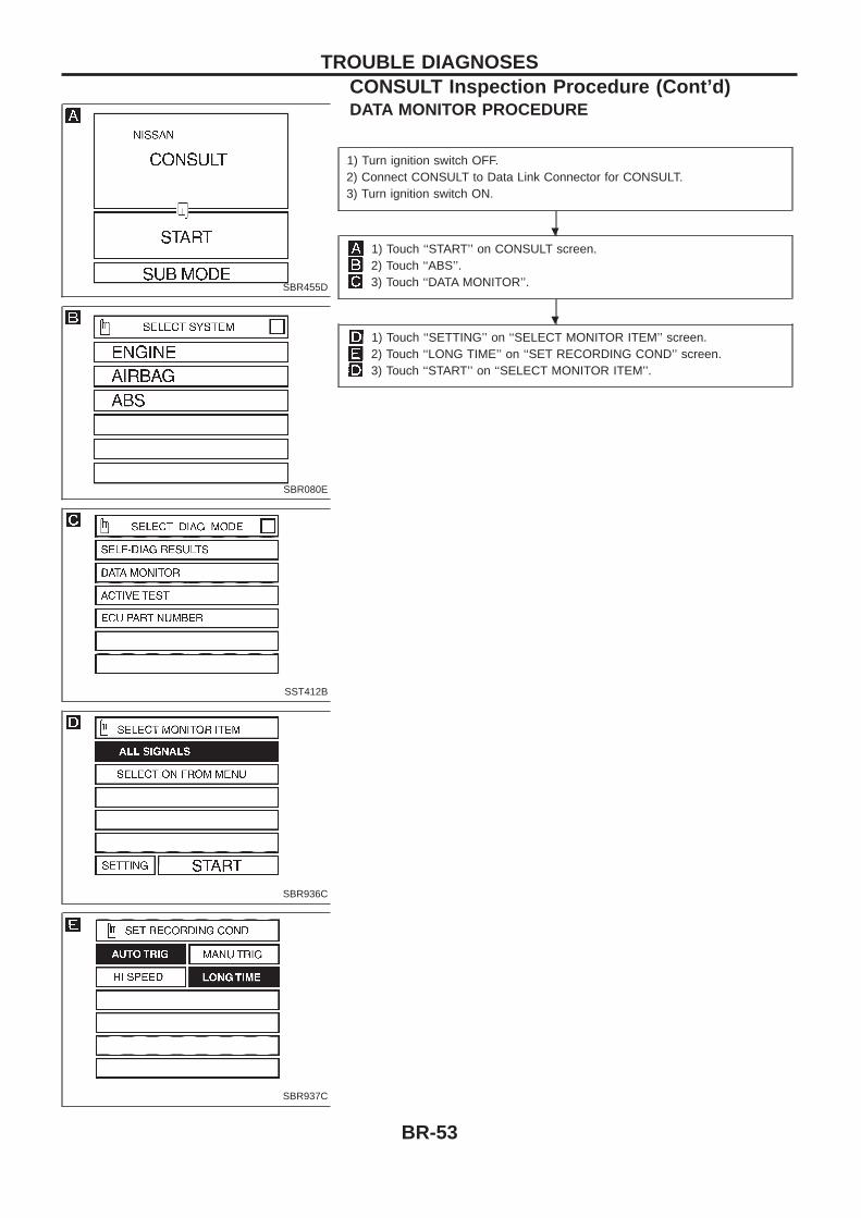
DATA MONITOR PROCEDURE
1) Turn ignition switch OFF.2) Connect CONSULT to Data Link Connector for CONSULT.3) Turn ignition switch ON.
1) Touch ‘‘START’’ on CONSULT screen.2) Touch ‘‘ABS’’.3) Touch ‘‘DATA MONITOR’’.
1) Touch ‘‘SETTING’’ on ‘‘SELECT MONITOR ITEM’’ screen.2) Touch ‘‘LONG TIME’’ on ‘‘SET RECORDING COND’’ screen.3) Touch ‘‘START’’ on ‘‘SELECT MONITOR ITEM’’.
SBR455D
SBR080E
SST412B
SBR936C
SBR937C
.
.
TROUBLE DIAGNOSESCONSULT Inspection Procedure (Cont’d)
BR-53
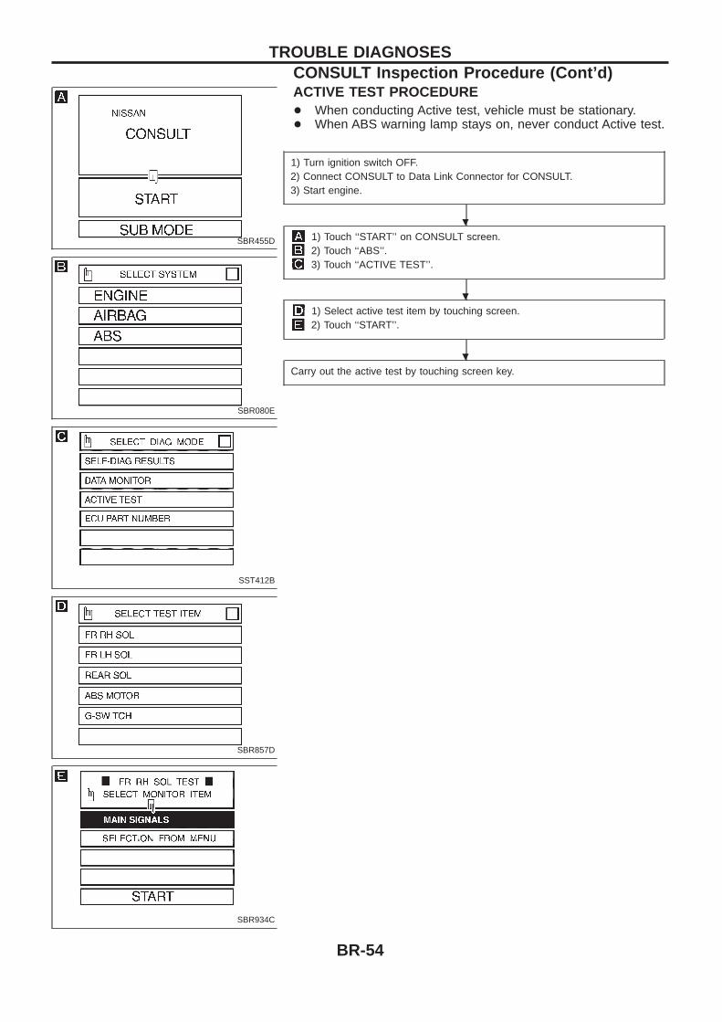
ACTIVE TEST PROCEDURE+ When conducting Active test, vehicle must be stationary.+ When ABS warning lamp stays on, never conduct Active test.
1) Turn ignition switch OFF.2) Connect CONSULT to Data Link Connector for CONSULT.3) Start engine.
1) Touch ‘‘START’’ on CONSULT screen.2) Touch ‘‘ABS’’.3) Touch ‘‘ACTIVE TEST’’.
1) Select active test item by touching screen.2) Touch ‘‘START’’.
Carry out the active test by touching screen key.
SBR455D
SBR080E
SST412B
SBR857D
SBR934C
.
.
.
TROUBLE DIAGNOSESCONSULT Inspection Procedure (Cont’d)
BR-54
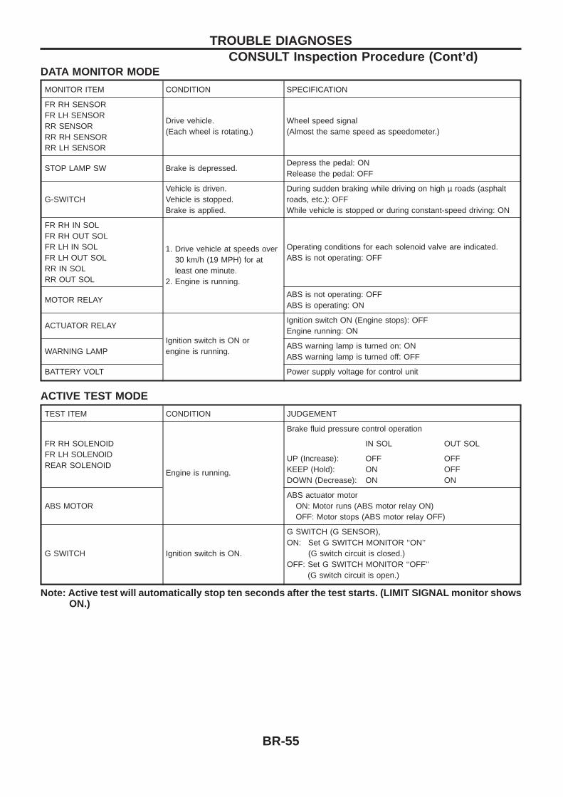
DATA MONITOR MODE
MONITOR ITEM CONDITION SPECIFICATION
FR RH SENSORFR LH SENSORRR SENSORRR RH SENSORRR LH SENSOR
Drive vehicle.(Each wheel is rotating.)
Wheel speed signal(Almost the same speed as speedometer.)
STOP LAMP SW Brake is depressed.Depress the pedal: ONRelease the pedal: OFF
G-SWITCHVehicle is driven.Vehicle is stopped.Brake is applied.
During sudden braking while driving on high µ roads (asphaltroads, etc.): OFFWhile vehicle is stopped or during constant-speed driving: ON
FR RH IN SOLFR RH OUT SOLFR LH IN SOLFR LH OUT SOLRR IN SOLRR OUT SOL
1. Drive vehicle at speeds over30 km/h (19 MPH) for atleast one minute.
2. Engine is running.
Operating conditions for each solenoid valve are indicated.ABS is not operating: OFF
MOTOR RELAYABS is not operating: OFFABS is operating: ON
ACTUATOR RELAY
Ignition switch is ON orengine is running.
Ignition switch ON (Engine stops): OFFEngine running: ON
WARNING LAMPABS warning lamp is turned on: ONABS warning lamp is turned off: OFF
BATTERY VOLT Power supply voltage for control unit
ACTIVE TEST MODE
TEST ITEM CONDITION JUDGEMENT
FR RH SOLENOIDFR LH SOLENOIDREAR SOLENOID
Engine is running.
Brake fluid pressure control operation
IN SOL OUT SOL
UP (Increase):KEEP (Hold):DOWN (Decrease):
OFFONON
OFFOFFON
ABS MOTORABS actuator motor
ON: Motor runs (ABS motor relay ON)OFF: Motor stops (ABS motor relay OFF)
G SWITCH Ignition switch is ON.
G SWITCH (G SENSOR),ON: Set G SWITCH MONITOR ‘‘ON’’
(G switch circuit is closed.)OFF: Set G SWITCH MONITOR ‘‘OFF’’
(G switch circuit is open.)
Note: Active test will automatically stop ten seconds after the test starts. (LIMIT SIGNAL monitor showsON.)
TROUBLE DIAGNOSESCONSULT Inspection Procedure (Cont’d)
BR-55
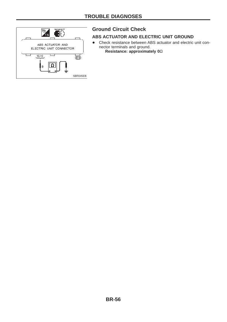
Ground Circuit CheckABS ACTUATOR AND ELECTRIC UNIT GROUND+ Check resistance between ABS actuator and electric unit con-
nector terminals and ground.Resistance: approximately 0 Ω
SBR045EB
TROUBLE DIAGNOSES
BR-56
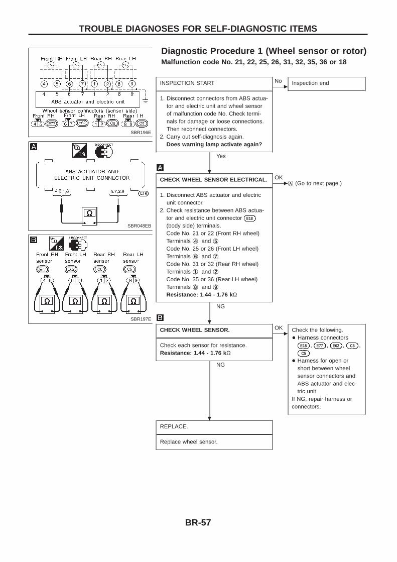
Diagnostic Procedure 1 (Wheel sensor or rotor)Malfunction code No. 21, 22, 25, 26, 31, 32, 35, 36 or 18
INSPECTION START----------------------------------------------------------------------------------------------------------------------------------------------------------------------------------------------------------------------------------------------------------------------------------------------------------------
1. Disconnect connectors from ABS actua-tor and electric unit and wheel sensorof malfunction code No. Check termi-nals for damage or loose connections.Then reconnect connectors.
2. Carry out self-diagnosis again.Does warning lamp activate again?
Yes
cNo Inspection end
CHECK WHEEL SENSOR ELECTRICAL.----------------------------------------------------------------------------------------------------------------------------------------------------------------------------------------------------------------------------------------------------------------------------------------------------------------
1. Disconnect ABS actuator and electricunit connector.
2. Check resistance between ABS actua-tor and electric unit connector E18
(body side) terminals.Code No. 21 or 22 (Front RH wheel)Terminals j4 and j5Code No. 25 or 26 (Front LH wheel)Terminals j6 and j7Code No. 31 or 32 (Rear RH wheel)Terminals j1 and j2Code No. 35 or 36 (Rear LH wheel)Terminals j8 and j9Resistance: 1.44 - 1.76 k Ω
NG
cOK
jA (Go to next page.)
CHECK WHEEL SENSOR.----------------------------------------------------------------------------------------------------------------------------------------------------------------------------------------------------------------------------------------------------------------------------------------------------------------
Check each sensor for resistance.Resistance: 1.44 - 1.76 k Ω
NG
cOK Check the following.
+ Harness connectorsE18 , E77 , E62 , C6 ,C5
+ Harness for open orshort between wheelsensor connectors andABS actuator and elec-tric unit
If NG, repair harness orconnectors.
REPLACE.----------------------------------------------------------------------------------------------------------------------------------------------------------------------------------------------------------------------------------------------------------------------------------------------------------------
Replace wheel sensor.
SBR196E
SBR048EB
SBR197E
.
.
.
TROUBLE DIAGNOSES FOR SELF-DIAGNOSTIC ITEMS
BR-57
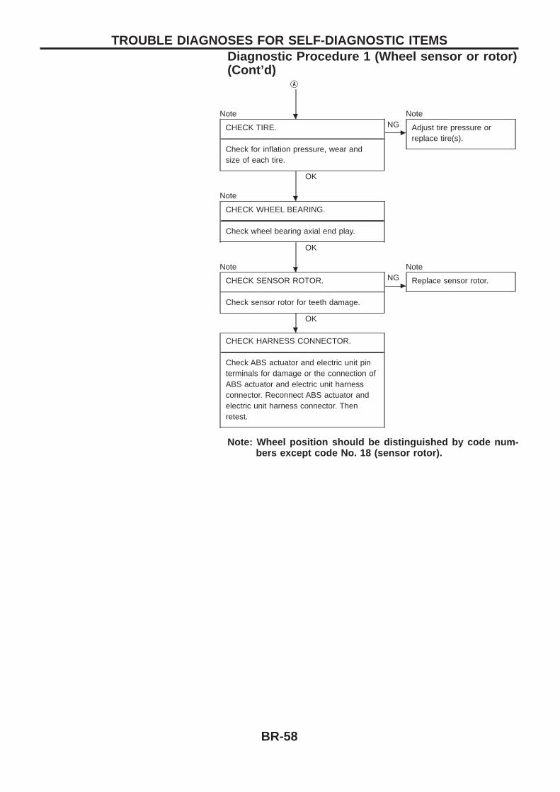
jA
Note
CHECK TIRE.----------------------------------------------------------------------------------------------------------------------------------------------------------------------------------------------------------------------------------------------------------------------------------------------------------------
Check for inflation pressure, wear andsize of each tire.
OK
cNG
Note
Adjust tire pressure orreplace tire(s).
Note
CHECK WHEEL BEARING.----------------------------------------------------------------------------------------------------------------------------------------------------------------------------------------------------------------------------------------------------------------------------------------------------------------
Check wheel bearing axial end play.
OK
Note
CHECK SENSOR ROTOR.----------------------------------------------------------------------------------------------------------------------------------------------------------------------------------------------------------------------------------------------------------------------------------------------------------------
Check sensor rotor for teeth damage.
OK
cNG
Note
Replace sensor rotor.
CHECK HARNESS CONNECTOR.----------------------------------------------------------------------------------------------------------------------------------------------------------------------------------------------------------------------------------------------------------------------------------------------------------------
Check ABS actuator and electric unit pinterminals for damage or the connection ofABS actuator and electric unit harnessconnector. Reconnect ABS actuator andelectric unit harness connector. Thenretest.
Note: Wheel position should be distinguished by code num-bers except code No. 18 (sensor rotor).
.
.
.
.
TROUBLE DIAGNOSES FOR SELF-DIAGNOSTIC ITEMSDiagnostic Procedure 1 (Wheel sensor or rotor)(Cont’d)
BR-58
Diagnostic Procedure 2 (ABS actuator solenoidvalve and solenoid valve relay)Malfunction code No. 41, 45, 55, 42, 46, 56, 63
CHECK FUSIBLE LINK.----------------------------------------------------------------------------------------------------------------------------------------------------------------------------------------------------------------------------------------------------------------------------------------------------------------Check 30A fusible link i . For fusible linklayout, refer to POWER SUPPLY ROUT-ING in EL section.
OK
cNG
jA (Go to next page.)
CHECK FUSE.----------------------------------------------------------------------------------------------------------------------------------------------------------------------------------------------------------------------------------------------------------------------------------------------------------------
Check 7.5A fuse 7 . For fuse layout, referto POWER SUPPLY ROUTING in EL sec-tion.
OK
cNG
jB (Go to next page.)
CHECK CONNECTOR.----------------------------------------------------------------------------------------------------------------------------------------------------------------------------------------------------------------------------------------------------------------------------------------------------------------
1. Disconnect ABS actuator and electricunit connector. Check terminals fordamage or loose connection. Thenreconnect connector.
2. Carry out self-diagnosis again.Does warning lamp activate again?
Yes
cNo Inspection end
CHECK ABS ACTUATOR AND ELECTRICUNIT GROUND CIRCUIT.
----------------------------------------------------------------------------------------------------------------------------------------------------------------------------------------------------------------------------------------------------------------------------------------------------------------Refer to ABS ACTUATOR AND ELECTRICUNIT GROUND in Ground Circuit Check,BR-56.
OK
cNG Repair harness and con-
nector.
CHECK SOLENOID VALVE RELAYPOWER SUPPLY CIRCUIT.
----------------------------------------------------------------------------------------------------------------------------------------------------------------------------------------------------------------------------------------------------------------------------------------------------------------1. Disconnect ABS actuator and electric
unit connector.2. Check voltage between ABS actuator
and electric unit connector E18 (bodyside) terminal j18 and ground.Battery voltage should exist.
OK
cNG Check the following.
+ Harness connector E18
+ Harness for open orshort between ABSactuator and electric unitand fusible link
If NG, repair harness orconnector.
REPLACE.----------------------------------------------------------------------------------------------------------------------------------------------------------------------------------------------------------------------------------------------------------------------------------------------------------------Replace ABS actuator and electric unit.
SBR198E
SBR052EB
.
.
.
.
.
TROUBLE DIAGNOSES FOR SELF-DIAGNOSTIC ITEMS
BR-59

jA
REPLACE.----------------------------------------------------------------------------------------------------------------------------------------------------------------------------------------------------------------------------------------------------------------------------------------------------------------Replace fusible link.Does the fusible link blow out whenignition switch is turned ‘‘ON’’?
Yes
cNo Inspection end
CHECK SOLENOID VALVE RELAYPOWER SUPPLY CIRCUIT.
----------------------------------------------------------------------------------------------------------------------------------------------------------------------------------------------------------------------------------------------------------------------------------------------------------------1. Disconnect ABS actuator and electric
unit connector.2. Check continuity between ABS actuator
and electric unit connector E18 (bodyside) terminal j18 and ground.Continuity should not exit.
OK
cNG Check the following.
+ Harness connector E18
+ Harness for open or shortbetween ABS actuatorand electric unit andfusible link
If NG, repair harness orconnector.
REPLACE.----------------------------------------------------------------------------------------------------------------------------------------------------------------------------------------------------------------------------------------------------------------------------------------------------------------Replace ABS actuator and electric unit.
jB
REPLACE.----------------------------------------------------------------------------------------------------------------------------------------------------------------------------------------------------------------------------------------------------------------------------------------------------------------
Replace fuse.Does the fuse blow out when ignitionswitch is turned ‘‘ON’’?
No
cYes Check the following.
+ Harness connector E18
+ Harness for open orshort between ABSactuator and electric unitand fuse
If NG, repair harness orconnector.
END----------------------------------------------------------------------------------------------------------------------------------------------------------------------------------------------------------------------------------------------------------------------------------------------------------------
INSPECTION END
SBR053EB
.
.
.
.
.
TROUBLE DIAGNOSES FOR SELF-DIAGNOSTIC ITEMSDiagnostic Procedure 2 (ABS actuator solenoidvalve and solenoid valve relay) (Cont’d)
BR-60
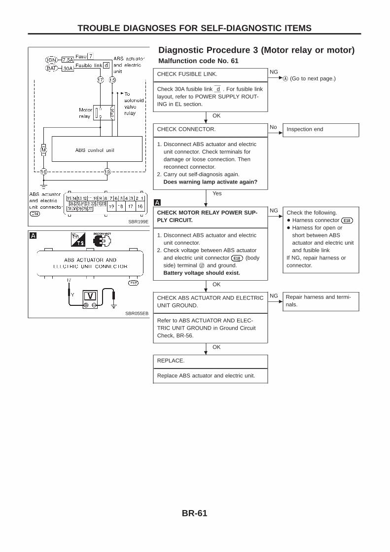
Diagnostic Procedure 3 (Motor relay or motor)Malfunction code No. 61
CHECK FUSIBLE LINK.----------------------------------------------------------------------------------------------------------------------------------------------------------------------------------------------------------------------------------------------------------------------------------------------------------------
Check 30A fusible link d . For fusible linklayout, refer to POWER SUPPLY ROUT-ING in EL section.
OK
cNG
jA (Go to next page.)
CHECK CONNECTOR.----------------------------------------------------------------------------------------------------------------------------------------------------------------------------------------------------------------------------------------------------------------------------------------------------------------
1. Disconnect ABS actuator and electricunit connector. Check terminals fordamage or loose connection. Thenreconnect connector.
2. Carry out self-diagnosis again.Does warning lamp activate again?
Yes
cNo Inspection end
CHECK MOTOR RELAY POWER SUP-PLY CIRCUIT.
----------------------------------------------------------------------------------------------------------------------------------------------------------------------------------------------------------------------------------------------------------------------------------------------------------------1. Disconnect ABS actuator and electric
unit connector.2. Check voltage between ABS actuator
and electric unit connector E18 (bodyside) terminal j17 and ground.Battery voltage should exist.
OK
cNG Check the following.
+ Harness connector E18
+ Harness for open orshort between ABSactuator and electric unitand fusible link
If NG, repair harness orconnector.
CHECK ABS ACTUATOR AND ELECTRICUNIT GROUND.
----------------------------------------------------------------------------------------------------------------------------------------------------------------------------------------------------------------------------------------------------------------------------------------------------------------Refer to ABS ACTUATOR AND ELEC-TRIC UNIT GROUND in Ground CircuitCheck, BR-56.
OK
cNG Repair harness and termi-
nals.
REPLACE.----------------------------------------------------------------------------------------------------------------------------------------------------------------------------------------------------------------------------------------------------------------------------------------------------------------
Replace ABS actuator and electric unit.
SBR199E
SBR055EB
.
.
.
.
TROUBLE DIAGNOSES FOR SELF-DIAGNOSTIC ITEMS
BR-61
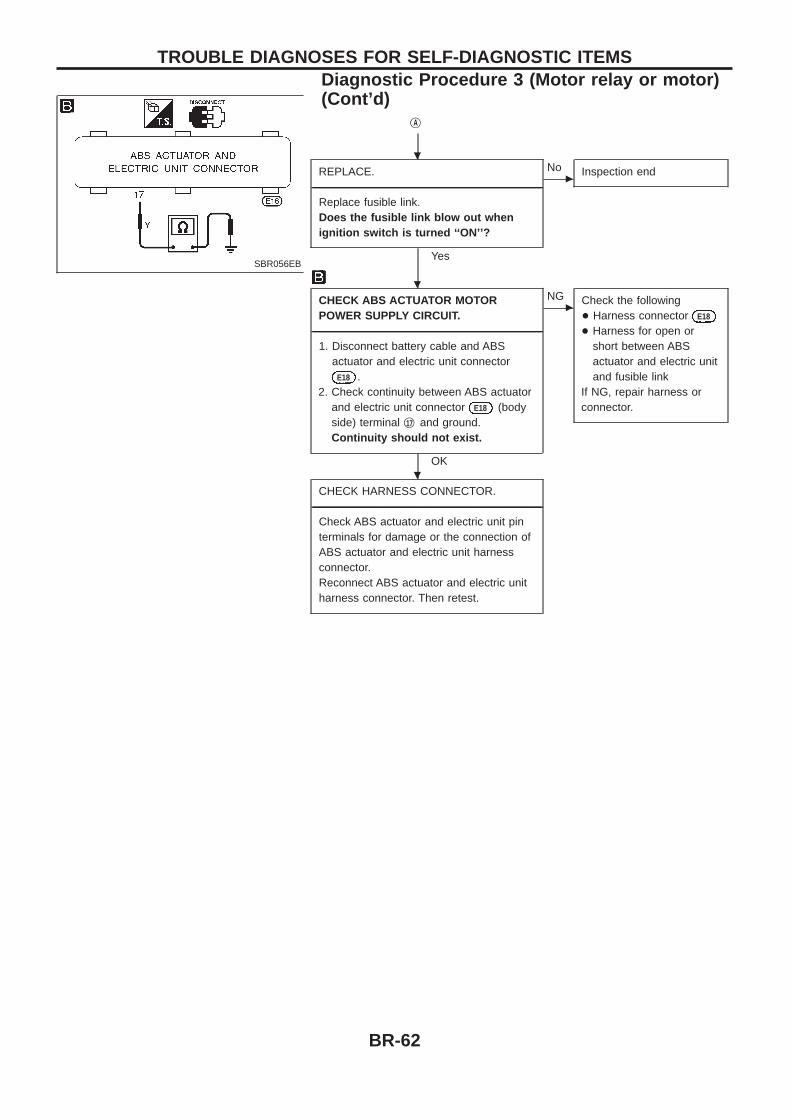
jA
REPLACE.----------------------------------------------------------------------------------------------------------------------------------------------------------------------------------------------------------------------------------------------------------------------------------------------------------------
Replace fusible link.Does the fusible link blow out whenignition switch is turned ‘‘ON’’?
Yes
cNo Inspection end
CHECK ABS ACTUATOR MOTORPOWER SUPPLY CIRCUIT.
----------------------------------------------------------------------------------------------------------------------------------------------------------------------------------------------------------------------------------------------------------------------------------------------------------------1. Disconnect battery cable and ABS
actuator and electric unit connectorE18 .
2. Check continuity between ABS actuatorand electric unit connector E18 (bodyside) terminal j17 and ground.Continuity should not exist.
OK
cNG Check the following
+ Harness connector E18
+ Harness for open orshort between ABSactuator and electric unitand fusible link
If NG, repair harness orconnector.
CHECK HARNESS CONNECTOR.----------------------------------------------------------------------------------------------------------------------------------------------------------------------------------------------------------------------------------------------------------------------------------------------------------------
Check ABS actuator and electric unit pinterminals for damage or the connection ofABS actuator and electric unit harnessconnector.Reconnect ABS actuator and electric unitharness connector. Then retest.
SBR056EB
.
.
.
TROUBLE DIAGNOSES FOR SELF-DIAGNOSTIC ITEMSDiagnostic Procedure 3 (Motor relay or motor)(Cont’d)
BR-62
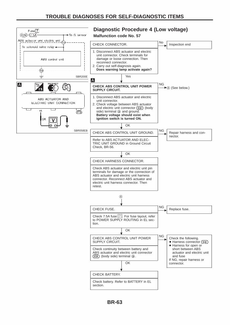
Diagnostic Procedure 4 (Low voltage)Malfunction code No. 57
CHECK CONNECTOR.----------------------------------------------------------------------------------------------------------------------------------------------------------------------------------------------------------------------------------------------------------------------------------------------------------------
1. Disconnect ABS actuator and electricunit connector. Check terminals fordamage or loose connection. Thenreconnect connector.
2. Carry out self-diagnosis again.Does warning lamp activate again?
Yes
cNo
Inspection end
CHECK ABS CONTROL UNIT POWERSUPPLY CIRCUIT.
----------------------------------------------------------------------------------------------------------------------------------------------------------------------------------------------------------------------------------------------------------------------------------------------------------------1. Disconnect ABS actuator and electric
unit connector.2. Check voltage between ABS actuator
and electric unit connector E18 (bodyside) terminal j15 and ground.Battery voltage should exist whenignition switch is turned ON.
OK
cNG
jA (See below.)
CHECK ABS CONTROL UNIT GROUND.----------------------------------------------------------------------------------------------------------------------------------------------------------------------------------------------------------------------------------------------------------------------------------------------------------------
Refer to ABS ACTUATOR AND ELEC-TRIC UNIT GROUND in Ground CircuitCheck, BR-56.
OK
cNG
Repair harness and con-nector.
CHECK HARNESS CONNECTOR.----------------------------------------------------------------------------------------------------------------------------------------------------------------------------------------------------------------------------------------------------------------------------------------------------------------
Check ABS actuator and electric unit pinterminals for damage or the connection ofABS actuator and electric unit harnessconnector. Reconnect ABS actuator andelectric unit harness connector. Thenretest.
jA
CHECK FUSE.----------------------------------------------------------------------------------------------------------------------------------------------------------------------------------------------------------------------------------------------------------------------------------------------------------------
Check 7.5A fuse 7 . For fuse layout, referto POWER SUPPLY ROUTING in EL sec-tion.
OK
cNG
Replace fuse.
CHECK ABS CONTROL UNIT POWERSUPPLY CIRCUIT.
----------------------------------------------------------------------------------------------------------------------------------------------------------------------------------------------------------------------------------------------------------------------------------------------------------------Check continuity between battery andABS actuator and electric unit connector
E18 (body side) terminal j15 .
OK
cNG
Check the following.+ Harness connector E18+ Harness for open or
short between ABSactuator and electric unitand fuse
If NG, repair harness orconnector.
CHECK BATTERY.----------------------------------------------------------------------------------------------------------------------------------------------------------------------------------------------------------------------------------------------------------------------------------------------------------------
Check battery. Refer to BATTERY in ELsection.
SBR200E
SBR058EB
.
.
.
.
.
.
TROUBLE DIAGNOSES FOR SELF-DIAGNOSTIC ITEMS
BR-63
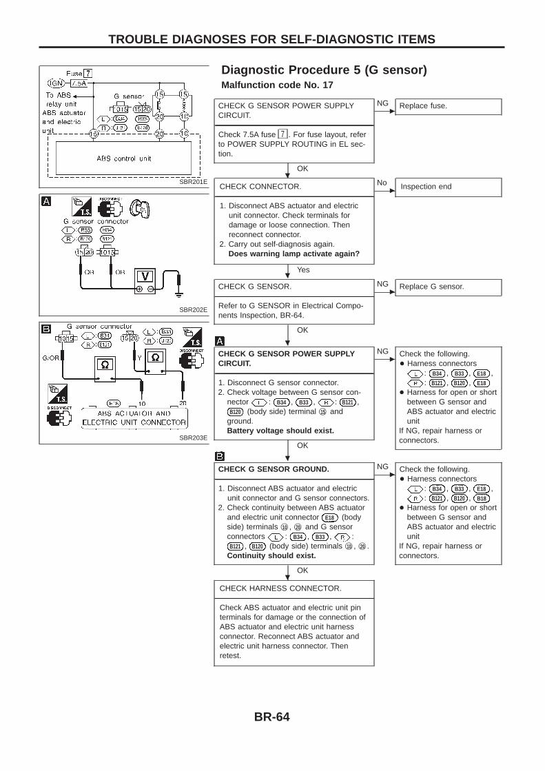
Diagnostic Procedure 5 (G sensor)Malfunction code No. 17
CHECK G SENSOR POWER SUPPLYCIRCUIT.
----------------------------------------------------------------------------------------------------------------------------------------------------------------------------------------------------------------------------------------------------------------------------------------------------------------Check 7.5A fuse 7 . For fuse layout, referto POWER SUPPLY ROUTING in EL sec-tion.
OK
cNG Replace fuse.
CHECK CONNECTOR.----------------------------------------------------------------------------------------------------------------------------------------------------------------------------------------------------------------------------------------------------------------------------------------------------------------
1. Disconnect ABS actuator and electricunit connector. Check terminals fordamage or loose connection. Thenreconnect connector.
2. Carry out self-diagnosis again.Does warning lamp activate again?
Yes
cNo Inspection end
CHECK G SENSOR.----------------------------------------------------------------------------------------------------------------------------------------------------------------------------------------------------------------------------------------------------------------------------------------------------------------Refer to G SENSOR in Electrical Compo-nents Inspection, BR-64.
OK
cNG Replace G sensor.
CHECK G SENSOR POWER SUPPLYCIRCUIT.
----------------------------------------------------------------------------------------------------------------------------------------------------------------------------------------------------------------------------------------------------------------------------------------------------------------1. Disconnect G sensor connector.2. Check voltage between G sensor con-
nector : B34 , B33 , : B121 ,B120 (body side) terminal j15 and
ground.Battery voltage should exist.
OK
cNG Check the following.
+ Harness connectors: B34 , B33 , E18 ,: B121 , B120 , E18
+ Harness for open or shortbetween G sensor andABS actuator and electricunit
If NG, repair harness orconnectors.
CHECK G SENSOR GROUND.----------------------------------------------------------------------------------------------------------------------------------------------------------------------------------------------------------------------------------------------------------------------------------------------------------------1. Disconnect ABS actuator and electric
unit connector and G sensor connectors.2. Check continuity between ABS actuator
and electric unit connector E18 (bodyside) terminals j10 , j20 and G sensorconnectors : B34 , B33 , :
B121 , B120 (body side) terminals j10 , j20 .Continuity should exist.
OK
cNG Check the following.
+ Harness connectors: B34 , B33 , E18 ,: B121 , B120 , B18
+ Harness for open or shortbetween G sensor andABS actuator and electricunit
If NG, repair harness orconnectors.
CHECK HARNESS CONNECTOR.----------------------------------------------------------------------------------------------------------------------------------------------------------------------------------------------------------------------------------------------------------------------------------------------------------------
Check ABS actuator and electric unit pinterminals for damage or the connection ofABS actuator and electric unit harnessconnector. Reconnect ABS actuator andelectric unit harness connector. Thenretest.
SBR201E
SBR202E
SBR203E
.
.
.
.
.
TROUBLE DIAGNOSES FOR SELF-DIAGNOSTIC ITEMS
BR-64
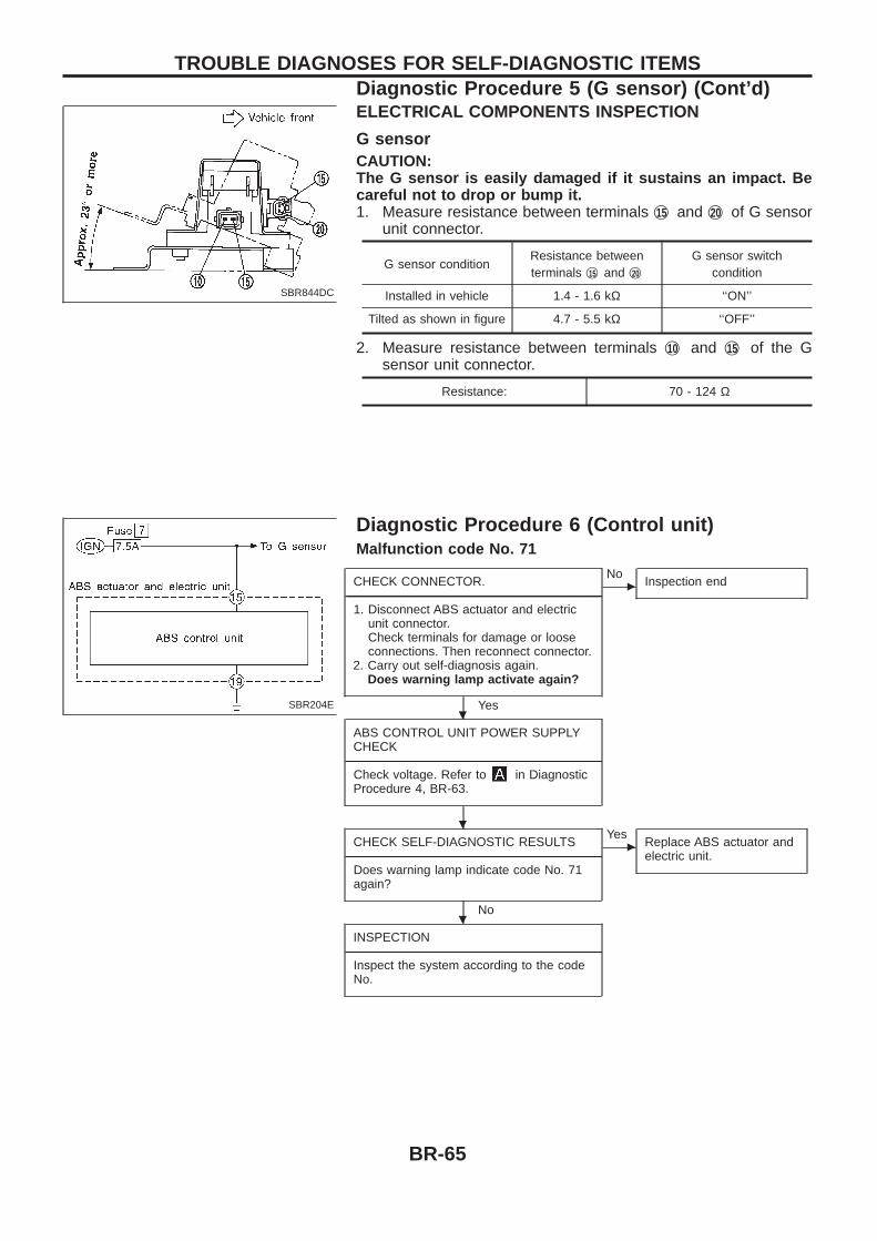
ELECTRICAL COMPONENTS INSPECTION
G sensorCAUTION:The G sensor is easily damaged if it sustains an impact. Becareful not to drop or bump it.1. Measure resistance between terminals j15 and j20 of G sensor
unit connector.
G sensor conditionResistance betweenterminals j15 and j20
G sensor switchcondition
Installed in vehicle 1.4 - 1.6 kΩ ‘‘ON’’
Tilted as shown in figure 4.7 - 5.5 kΩ ‘‘OFF’’
2. Measure resistance between terminals j10 and j15 of the Gsensor unit connector.
Resistance: 70 - 124 Ω
Diagnostic Procedure 6 (Control unit)Malfunction code No. 71
CHECK CONNECTOR.----------------------------------------------------------------------------------------------------------------------------------------------------------------------------------------------------------------------------------------------------------------------------------------------------------------
1. Disconnect ABS actuator and electricunit connector.Check terminals for damage or looseconnections. Then reconnect connector.
2. Carry out self-diagnosis again.Does warning lamp activate again?
Yes
cNo
Inspection end
ABS CONTROL UNIT POWER SUPPLYCHECK
----------------------------------------------------------------------------------------------------------------------------------------------------------------------------------------------------------------------------------------------------------------------------------------------------------------Check voltage. Refer to in DiagnosticProcedure 4, BR-63.
CHECK SELF-DIAGNOSTIC RESULTS----------------------------------------------------------------------------------------------------------------------------------------------------------------------------------------------------------------------------------------------------------------------------------------------------------------
Does warning lamp indicate code No. 71again?
No
cYes
Replace ABS actuator andelectric unit.
INSPECTION----------------------------------------------------------------------------------------------------------------------------------------------------------------------------------------------------------------------------------------------------------------------------------------------------------------
Inspect the system according to the codeNo.
SBR844DC
SBR204E.
.
.
TROUBLE DIAGNOSES FOR SELF-DIAGNOSTIC ITEMSDiagnostic Procedure 5 (G sensor) (Cont’d)
BR-65
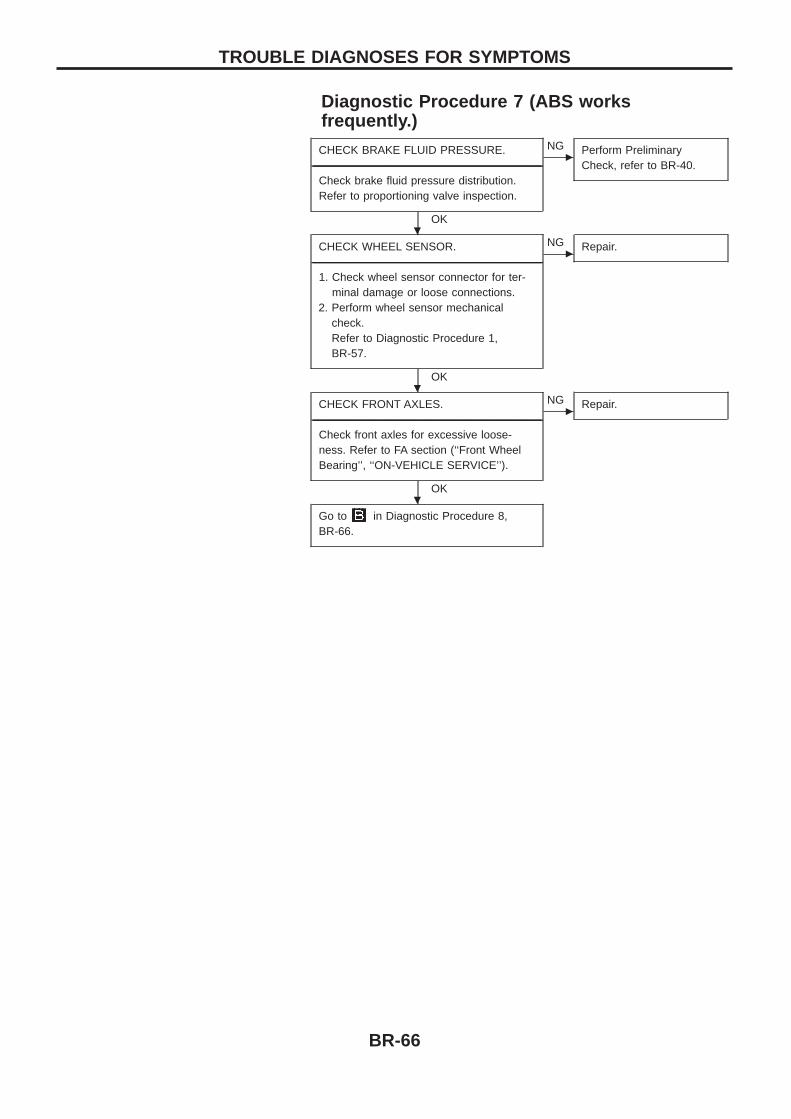
Diagnostic Procedure 7 (ABS worksfrequently.)
CHECK BRAKE FLUID PRESSURE.----------------------------------------------------------------------------------------------------------------------------------------------------------------------------------------------------------------------------------------------------------------------------------------------------------------
Check brake fluid pressure distribution.Refer to proportioning valve inspection.
OK
cNG Perform Preliminary
Check, refer to BR-40.
CHECK WHEEL SENSOR.----------------------------------------------------------------------------------------------------------------------------------------------------------------------------------------------------------------------------------------------------------------------------------------------------------------
1. Check wheel sensor connector for ter-minal damage or loose connections.
2. Perform wheel sensor mechanicalcheck.Refer to Diagnostic Procedure 1,BR-57.
OK
cNG Repair.
CHECK FRONT AXLES.----------------------------------------------------------------------------------------------------------------------------------------------------------------------------------------------------------------------------------------------------------------------------------------------------------------
Check front axles for excessive loose-ness. Refer to FA section (‘‘Front WheelBearing’’, ‘‘ON-VEHICLE SERVICE’’).
OK
cNG Repair.
Go to in Diagnostic Procedure 8,BR-66.
.
.
.
TROUBLE DIAGNOSES FOR SYMPTOMS
BR-66
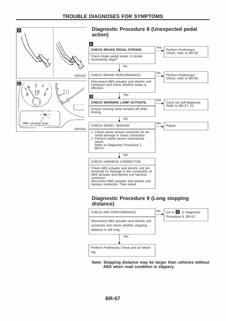
Diagnostic Procedure 8 (Unexpected pedalaction)
CHECK BRAKE PEDAL STROKE.----------------------------------------------------------------------------------------------------------------------------------------------------------------------------------------------------------------------------------------------------------------------------------------------------------------
Check brake pedal stroke. Is strokeexcessively large?
No
cYes
Perform PreliminaryCheck, refer to BR-40.
CHECK BRAKE PERFORMANCE.----------------------------------------------------------------------------------------------------------------------------------------------------------------------------------------------------------------------------------------------------------------------------------------------------------------
Disconnect ABS actuator and electric unitconnector and check whether brake iseffective.
Yes
cNo
Perform PreliminaryCheck, refer to BR-40.
CHECK WARNING LAMP ACTIVATE.----------------------------------------------------------------------------------------------------------------------------------------------------------------------------------------------------------------------------------------------------------------------------------------------------------------
Ensure warning lamp remains off whiledriving.
OK
cNG
Carry out self-diagnosis.Refer to BR-47, 51.
CHECK WHEEL SENSOR.----------------------------------------------------------------------------------------------------------------------------------------------------------------------------------------------------------------------------------------------------------------------------------------------------------------
1. Check wheel sensor connector for ter-minal damage or loose connection.
2. Perform wheel sensor mechanicalcheck.Refer to Diagnostic Procedure 1,BR-57.
OK
cNG
Repair.
CHECK HARNESS CONNECTOR.----------------------------------------------------------------------------------------------------------------------------------------------------------------------------------------------------------------------------------------------------------------------------------------------------------------
Check ABS actuator and electric unit pinterminals for damage or the connection ofABS actuator and electric unit harnessconnector.Reconnect ABS actuator and electric unitharness connector. Then retest.
Diagnostic Procedure 9 (Long stoppingdistance)
CHECK ABS PERFORMANCE.----------------------------------------------------------------------------------------------------------------------------------------------------------------------------------------------------------------------------------------------------------------------------------------------------------------
Disconnect ABS actuator and electric unitconnector and check whether stoppingdistance is still long.
Yes
cNo Go to in Diagnostic
Procedure 8, BR-67.
Perform Preliminary Check and air bleed-ing.
Note: Stopping distance may be larger than vehicles withoutABS when road condition is slippery.
SBR540A
SBR186E
.
.
.
.
.
TROUBLE DIAGNOSES FOR SYMPTOMS
BR-67
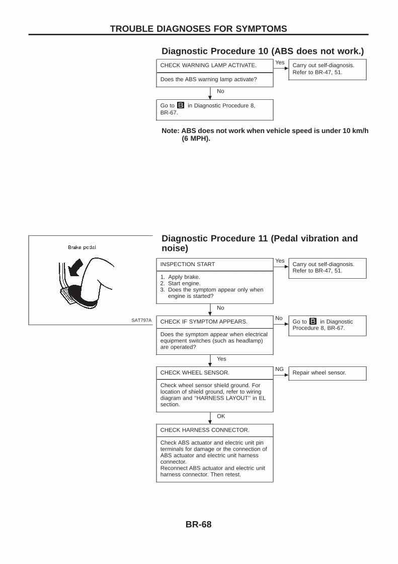
Diagnostic Procedure 10 (ABS does not work.)CHECK WARNING LAMP ACTIVATE.
----------------------------------------------------------------------------------------------------------------------------------------------------------------------------------------------------------------------------------------------------------------------------------------------------------------Does the ABS warning lamp activate?
No
cYes Carry out self-diagnosis.
Refer to BR-47, 51.
Go to in Diagnostic Procedure 8,BR-67.
Note: ABS does not work when vehicle speed is under 10 km/h(6 MPH).
Diagnostic Procedure 11 (Pedal vibration andnoise)
INSPECTION START----------------------------------------------------------------------------------------------------------------------------------------------------------------------------------------------------------------------------------------------------------------------------------------------------------------
1. Apply brake.2. Start engine.3. Does the symptom appear only when
engine is started?
No
cYes
Carry out self-diagnosis.Refer to BR-47, 51.
CHECK IF SYMPTOM APPEARS.----------------------------------------------------------------------------------------------------------------------------------------------------------------------------------------------------------------------------------------------------------------------------------------------------------------
Does the symptom appear when electricalequipment switches (such as headlamp)are operated?
Yes
cNo
Go to in DiagnosticProcedure 8, BR-67.
CHECK WHEEL SENSOR.----------------------------------------------------------------------------------------------------------------------------------------------------------------------------------------------------------------------------------------------------------------------------------------------------------------
Check wheel sensor shield ground. Forlocation of shield ground, refer to wiringdiagram and ‘‘HARNESS LAYOUT’’ in ELsection.
OK
cNG
Repair wheel sensor.
CHECK HARNESS CONNECTOR.----------------------------------------------------------------------------------------------------------------------------------------------------------------------------------------------------------------------------------------------------------------------------------------------------------------
Check ABS actuator and electric unit pinterminals for damage or the connection ofABS actuator and electric unit harnessconnector.Reconnect ABS actuator and electric unitharness connector. Then retest.
SAT797A
.
.
.
.
TROUBLE DIAGNOSES FOR SYMPTOMS
BR-68
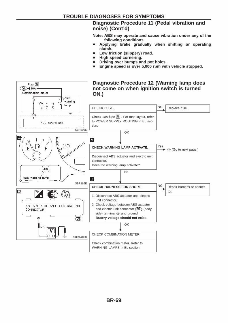
Note: ABS may operate and cause vibration under any of thefollowing conditions.
+ Applying brake gradually when shifting or operatingclutch.
+ Low friction (slippery) road.+ High speed cornering.+ Driving over bumps and pot holes.+ Engine speed is over 5,000 rpm with vehicle stopped.
Diagnostic Procedure 12 (Warning lamp doesnot come on when ignition switch is turnedON.)
CHECK FUSE.----------------------------------------------------------------------------------------------------------------------------------------------------------------------------------------------------------------------------------------------------------------------------------------------------------------
Check 10A fuse 28 . For fuse layout, referto POWER SUPPLY ROUTING in EL sec-tion.
OK
cNG Replace fuse.
CHECK WARNING LAMP ACTIVATE.----------------------------------------------------------------------------------------------------------------------------------------------------------------------------------------------------------------------------------------------------------------------------------------------------------------
Disconnect ABS actuator and electric unitconnector.Does the warning lamp activate?
No
cYes
jA (Go to next page.)
CHECK HARNESS FOR SHORT.----------------------------------------------------------------------------------------------------------------------------------------------------------------------------------------------------------------------------------------------------------------------------------------------------------------
1. Disconnect ABS actuator and electricunit connector.
2. Check voltage between ABS actuatorand electric unit connector E18 (bodyside) terminal j21 and ground.Battery voltage should not exist.
OK
cNG Repair harness or connec-
tor.
CHECK COMBINATION METER.----------------------------------------------------------------------------------------------------------------------------------------------------------------------------------------------------------------------------------------------------------------------------------------------------------------
Check combination meter. Refer toWARNING LAMPS in EL section.
SBR205E
SBR186E
SBR144EB
.
.
.
TROUBLE DIAGNOSES FOR SYMPTOMSDiagnostic Procedure 11 (Pedal vibration andnoise) (Cont’d)
BR-69
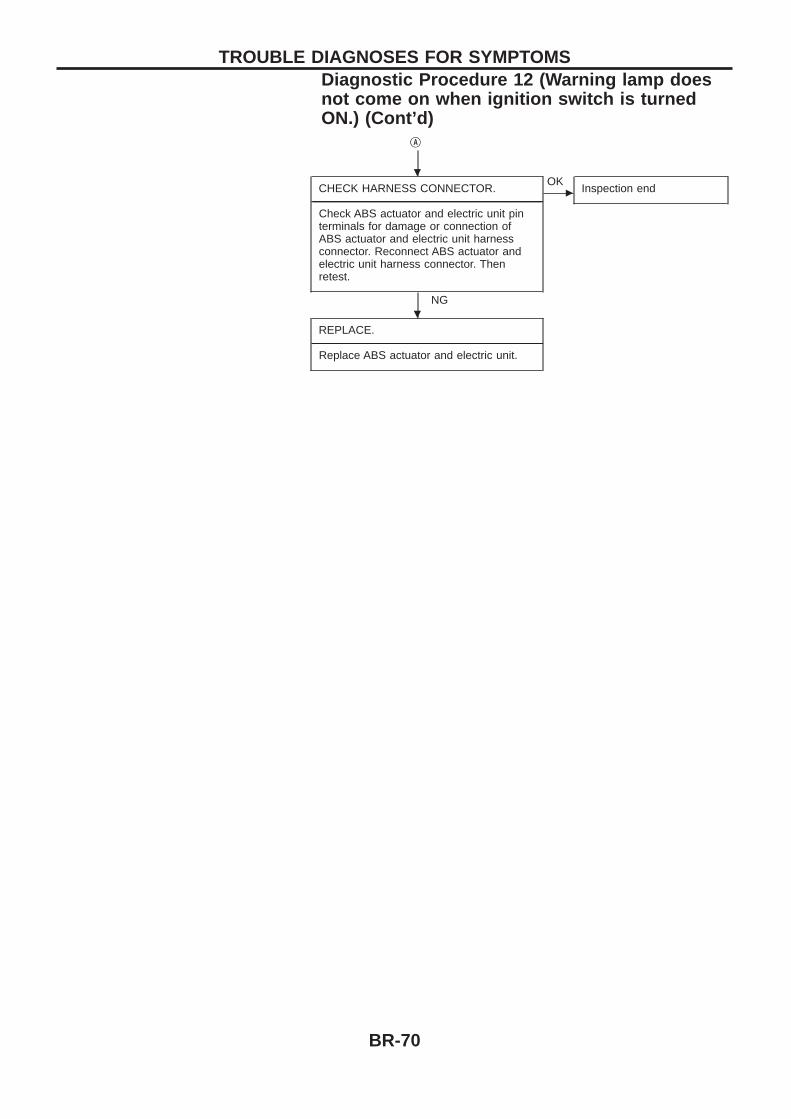
jA
CHECK HARNESS CONNECTOR.----------------------------------------------------------------------------------------------------------------------------------------------------------------------------------------------------------------------------------------------------------------------------------------------------------------
Check ABS actuator and electric unit pinterminals for damage or connection ofABS actuator and electric unit harnessconnector. Reconnect ABS actuator andelectric unit harness connector. Thenretest.
NG
cOK
Inspection end
REPLACE.----------------------------------------------------------------------------------------------------------------------------------------------------------------------------------------------------------------------------------------------------------------------------------------------------------------
Replace ABS actuator and electric unit.
.
.
TROUBLE DIAGNOSES FOR SYMPTOMSDiagnostic Procedure 12 (Warning lamp doesnot come on when ignition switch is turnedON.) (Cont’d)
BR-70
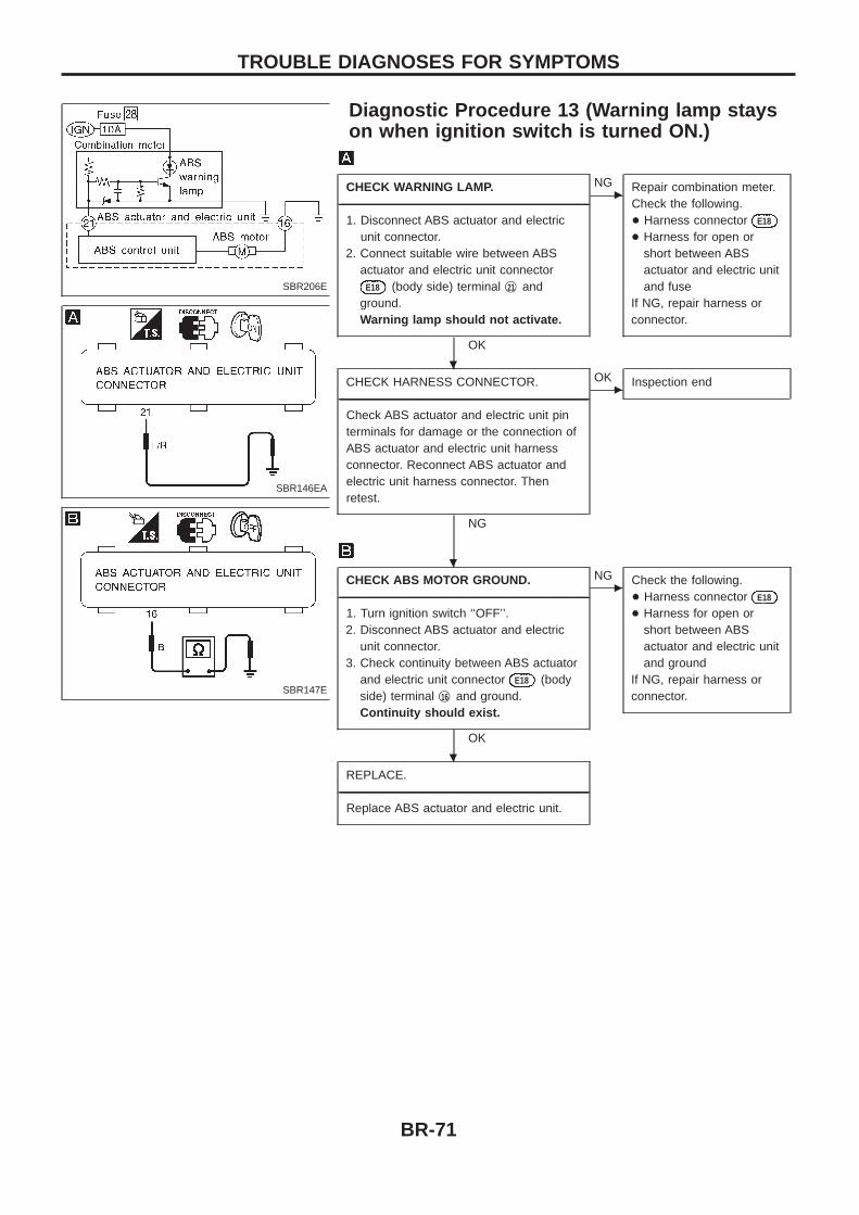
Diagnostic Procedure 13 (Warning lamp stayson when ignition switch is turned ON.)
CHECK WARNING LAMP.----------------------------------------------------------------------------------------------------------------------------------------------------------------------------------------------------------------------------------------------------------------------------------------------------------------
1. Disconnect ABS actuator and electricunit connector.
2. Connect suitable wire between ABSactuator and electric unit connector
E18 (body side) terminal j21 andground.Warning lamp should not activate.
OK
cNG Repair combination meter.
Check the following.+ Harness connector E18
+ Harness for open orshort between ABSactuator and electric unitand fuse
If NG, repair harness orconnector.
CHECK HARNESS CONNECTOR.----------------------------------------------------------------------------------------------------------------------------------------------------------------------------------------------------------------------------------------------------------------------------------------------------------------
Check ABS actuator and electric unit pinterminals for damage or the connection ofABS actuator and electric unit harnessconnector. Reconnect ABS actuator andelectric unit harness connector. Thenretest.
NG
cOK Inspection end
CHECK ABS MOTOR GROUND.----------------------------------------------------------------------------------------------------------------------------------------------------------------------------------------------------------------------------------------------------------------------------------------------------------------
1. Turn ignition switch ‘‘OFF’’.2. Disconnect ABS actuator and electric
unit connector.3. Check continuity between ABS actuator
and electric unit connector E18 (bodyside) terminal j16 and ground.Continuity should exist.
OK
cNG Check the following.
+ Harness connector E18
+ Harness for open orshort between ABSactuator and electric unitand ground
If NG, repair harness orconnector.
REPLACE.----------------------------------------------------------------------------------------------------------------------------------------------------------------------------------------------------------------------------------------------------------------------------------------------------------------
Replace ABS actuator and electric unit.
SBR206E
SBR146EA
SBR147E
.
.
.
TROUBLE DIAGNOSES FOR SYMPTOMS
BR-71
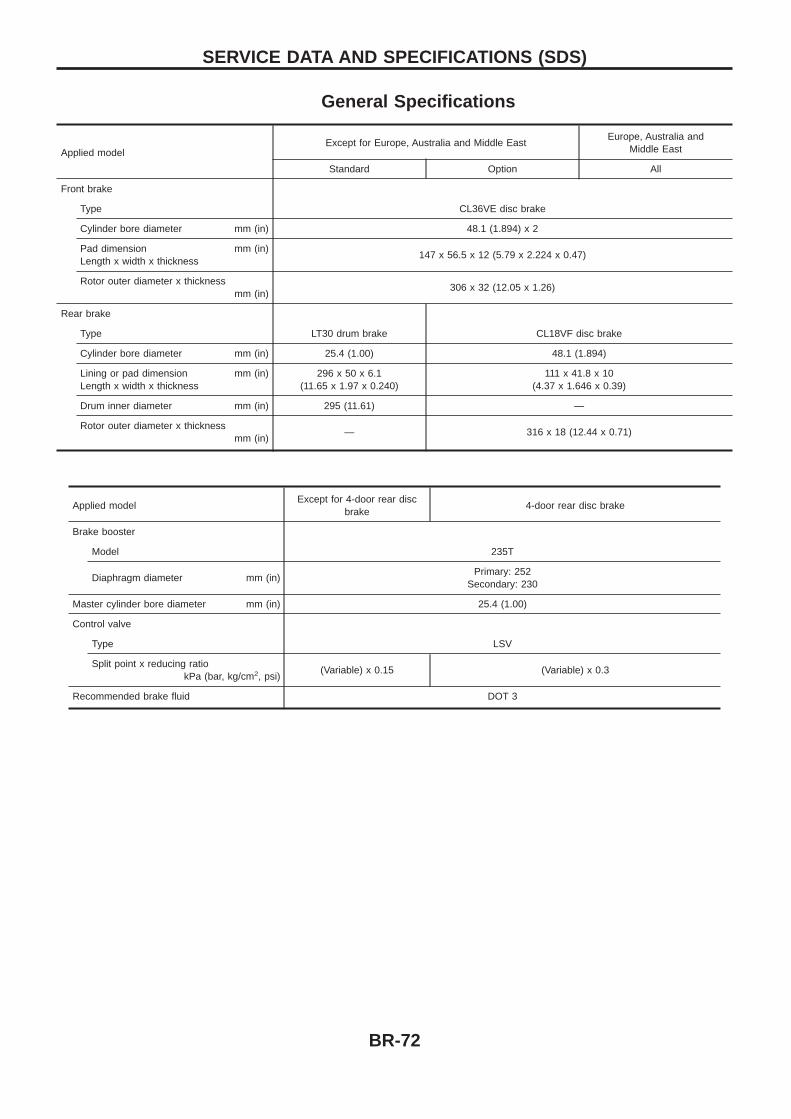
General Specifications
Applied modelExcept for Europe, Australia and Middle East
Europe, Australia andMiddle East
Standard Option All
Front brake
Type CL36VE disc brake
Cylinder bore diameter mm (in) 48.1 (1.894) x 2
Pad dimension mm (in)Length x width x thickness
147 x 56.5 x 12 (5.79 x 2.224 x 0.47)
Rotor outer diameter x thicknessmm (in)
306 x 32 (12.05 x 1.26)
Rear brake
Type LT30 drum brake CL18VF disc brake
Cylinder bore diameter mm (in) 25.4 (1.00) 48.1 (1.894)
Lining or pad dimension mm (in)Length x width x thickness
296 x 50 x 6.1(11.65 x 1.97 x 0.240)
111 x 41.8 x 10(4.37 x 1.646 x 0.39)
Drum inner diameter mm (in) 295 (11.61) —
Rotor outer diameter x thicknessmm (in)
— 316 x 18 (12.44 x 0.71)
Applied modelExcept for 4-door rear disc
brake4-door rear disc brake
Brake booster
Model 235T
Diaphragm diameter mm (in)Primary: 252
Secondary: 230
Master cylinder bore diameter mm (in) 25.4 (1.00)
Control valve
Type LSV
Split point x reducing ratiokPa (bar, kg/cm2, psi)
(Variable) x 0.15 (Variable) x 0.3
Recommended brake fluid DOT 3
SERVICE DATA AND SPECIFICATIONS (SDS)
BR-72
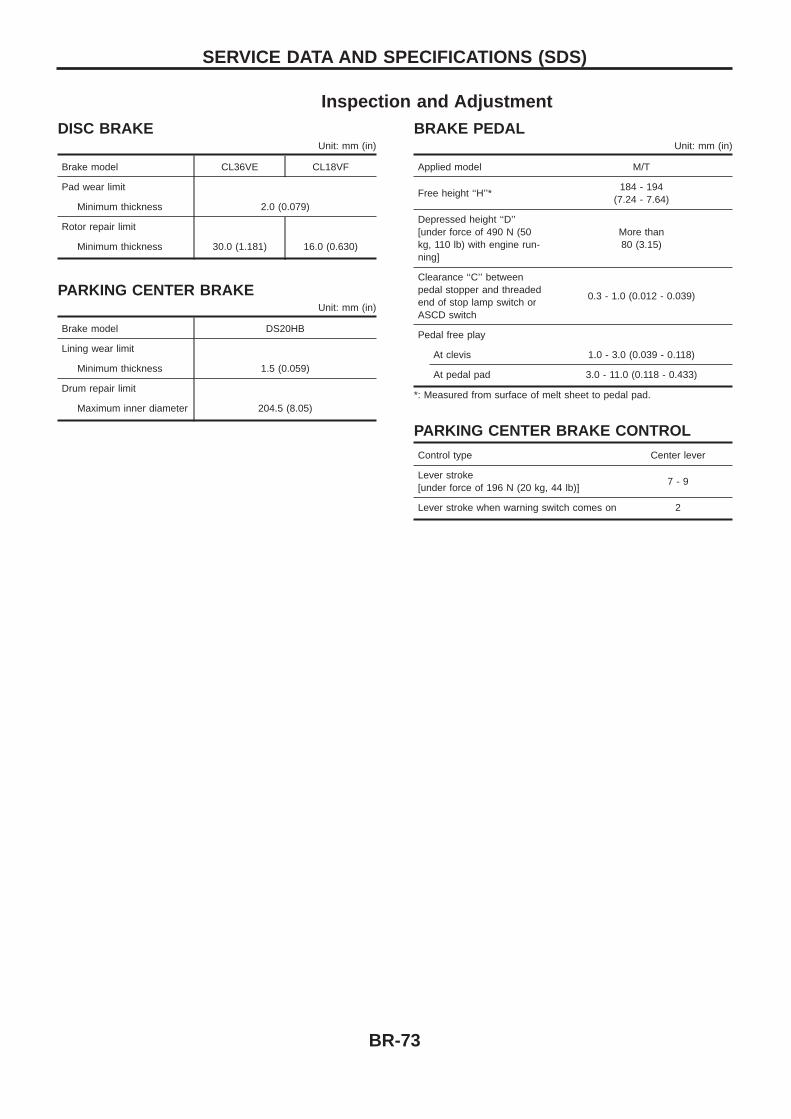
Inspection and AdjustmentDISC BRAKE
Unit: mm (in)
Brake model CL36VE CL18VF
Pad wear limit
Minimum thickness 2.0 (0.079)
Rotor repair limit
Minimum thickness 30.0 (1.181) 16.0 (0.630)
PARKING CENTER BRAKEUnit: mm (in)
Brake model DS20HB
Lining wear limit
Minimum thickness 1.5 (0.059)
Drum repair limit
Maximum inner diameter 204.5 (8.05)
BRAKE PEDALUnit: mm (in)
Applied model M/T
Free height ‘‘H’’*184 - 194
(7.24 - 7.64)
Depressed height ‘‘D’’[under force of 490 N (50kg, 110 lb) with engine run-ning]
More than80 (3.15)
Clearance ‘‘C’’ betweenpedal stopper and threadedend of stop lamp switch orASCD switch
0.3 - 1.0 (0.012 - 0.039)
Pedal free play
At clevis 1.0 - 3.0 (0.039 - 0.118)
At pedal pad 3.0 - 11.0 (0.118 - 0.433)
*: Measured from surface of melt sheet to pedal pad.
PARKING CENTER BRAKE CONTROL
Control type Center lever
Lever stroke[under force of 196 N (20 kg, 44 lb)]
7 - 9
Lever stroke when warning switch comes on 2
SERVICE DATA AND SPECIFICATIONS (SDS)
BR-73