Embed Size (px)
Citation preview

BRD4151A Reference ManualEFR32MG 2.4 GHz 19.5 dBm Radio Board
The EFR32MG family of Wireless SoCs deliver a high perform-ance, low energy wireless solution integrated into a small formfactor package.By combining a high performance 2.4 GHz RF transceiver with an energy efficient 32-bitMCU, the family provides designers the ultimate in flexibility with a family of pin-compati-ble devices that scale from 128/256 kB of flash and 16/32 kB of RAM. The ultra-lowpower operating modes and fast wake-up times of the Silicon Labs energy friendly 32-bit MCUs, combined with the low transmit and receive power consumption of the 2.4GHz radio, result in a solution optimized for battery powered applications.
RADIO BOARD FEATURES
• Wireless SoC:EFR32MG1P232F256GM48-B0
• CPU core: ARM Cortex-M4 with FPU• Flash memory: 256 kB• RAM: 32 kB• Operation frequency: 2.4 GHz• Transmit power: 19.5 dBm• Integrated PCB antenna, UFL connector
(optional).• Crystals for LFXO and HFXO: 32.768 kHz
and 38.4 MHz.
To develop and/or evaluate the EFR32 Mighty Gecko the EFR32MG Radio Board canbe connected to the Wireless Starter Kit Mainboard to get access to display, buttons andadditional features from Expansion Boards.
silabs.com | Smart. Connected. Energy-friendly. Rev. 1.3

1. Radio Board Connector
1.1 Introduction
The board-to-board connector scheme allows access to all EFR32MG1 GPIO pins as well as the RESETn signal. For more informationon the functions of the available pin functions, we refer you to the EFR32MG1 Datasheet.
1.2 Radio Board Connector Pin Associations
The figure below shows the pin mapping on the connector to the radio pins, and their function on the Wireless Starter Kit Mainboard.
GND
F9 / PA3 / VCOM.#RTS_#CS
3v3UIF_BUTTON1 / PF7 / P36
P200Upper Row
NC / P38NC / P40NC / P42NC / P44
DEBUG.TMS_SWDIO / PF1 / F0
DISP_ENABLE / PD15 / F14UIF_BUTTON0 / PF6 / F12
DISP_EXTCOMIN / PD13 / F10VCOM.#CTS_SCLK / PA2 / F8
NC / P4DEBUG.TDO_SWO / PF2 / F2
DISP_SI / PC6 / F16
VCOM.TX_MOSI / PA0 / F6
PTI.DATA / PB12 / F20DISP_EXTCOMIN / PD13 / F18
USB_VBUS5V
Board ID SCLGNDBoard ID SDA
USB_VREG
F7 / PA1 / VCOM.RX_MISOF5 / PA5 / VCOM_ENABLEF3 / PF3 / DEBUG.TDIF1 / PF0 / DEBUG.TCK_SWCLKP45 / NCP43 / NCP41 / NCP39 / NCP37 / High / SENSOR_ENABLE
F11 / PF5 / UIF_LED1F13 / PF7 / UIF_BUTTON1F15 / PC8 / DISP_SCLKF17 / PD14 / DISP_SCSF19 / PB13 / PTI.SYNCF21 / PB11 / PTI.CLK
GND VMCU_INVCOM.#CTS_SCLK / PA2 / P0
P201Lower Row
VCOM.#RTS_#CS / PA3 / P2PD10 / P4PD11 / P6
GND VRF_INP35 / PD15 / DISP_ENABLE
P7 / PC9P5 / PC8 / DISP_SCLKP3 / PC7P1 / PC6 / DISP_SI
P33 / PD14 / DISP_SCSP31 / PD13 / DISP_EXTCOMINP29 / NCP27 / NCP25 / NCP23 / NCP21 / NCP19 / NCP17 / NCP15 / NCP13 / PC11P11 / PA1 / VCOM.RX_MISOP9 / PA0 / VCOM.TX_MOSI
UIF_BUTTON0 / PF6 / P34UIF_LED1 / PF5 / P32UIF_LED0 / PF4 / P30
DEBUG.TDO_SWO / PF2 / P28DEBUG.TMS_SWDIO / PF1 / P26DEBUG.TCK_SWCLK / PF0 / P24
PTI.SYNC / PB13 / P22PTI.DATA / PB12 / P20
PTI.CLK / PB11 / P18VCOM_ENABLE / PA5 / P16
PA4 / P14PC10 / P12
DEBUG.TDI / PF3 / P10PD12 / P8
Figure 1.1 BRD4151A Radio Board Connector Pin Mapping
EFR32MG 2.4 GHz 19.5 dBm Radio BoardRadio Board Connector
silabs.com | Smart. Connected. Energy-friendly. Rev. 1.3 | 1

2. System-on-Chip Description
2.1 Introduction
The EFR32 product family features the world’s most energy friendly System-on-Chip radios. The devices are well suited for any batteryoperated application as well as other systems requiring high performance and low-energy consumption. This section gives a short intro-duction to the full radio and MCU system.
2.2 System-on-Chip Block Diagram
The block diagram of the EFR32MG1 is shown in the figure below.
Timers and Triggers
Real Time Counter and
Calendar
Cryotimer
Timer/Counter
Low Energy Timer
Pulse Counter
Watchdog Timer
Protocol Timer
32-bit bus
Peripheral Reflex System
Serial I/F I/O Ports Analog I/F
Lowest power mode with peripheral operational:
USART
Low Energy UARTTM
I2C
External Interrupts
General Purpose I/O
Pin Reset
Pin Wakeup
ADC
IDAC
Analog Comparator
Radio Transceiver
DEMOD
AGC
IFADC
CR
C
BU
FC
RFSENSE
MOD
FRC
RA
C
EM3—StopEM2—Deep SleepEM1—Sleep EM4—Hibernate EM4—ShutoffEM0—Active
PA
I
Q
RF FrontendLNA
Frequency Synthesizer
PGA
BALUN
Core / Memory
Flash Program Memory RAM Memory
ARM CortexTM M4 processor with DSP extensions and FPU
Memory Protection Unit
Debug Interface DMA Controlller
Other
CRYPTO
CRC
Clock Management
High Frequency Crystal Oscillator
High Frequency RC Oscillator
Low Frequency Crystal Oscillator
Low Frequency RC Oscillator
Ultra Low Frequency RC
Oscillator
Energy Management
Voltage Monitor
Brown-Out Detector
Power-On ResetDC/DC Regulator
Voltage Regulators
Auxiliary High Frequency RC
Oscillator
Figure 2.1 EFR32MG1 Block Diagram
EFR32MG 2.4 GHz 19.5 dBm Radio BoardSystem-on-Chip Description
silabs.com | Smart. Connected. Energy-friendly. Rev. 1.3 | 2

2.3 System Summary
The EFR32MG1 has the following main features:• Supports single-band operation in the 2.4 GHz band.• Cortex-M4 with FPU processor including a 32-bit RISC processor, also equipped with DSP instruction support and a floating-point
unit.• Supports two crystal oscillators and fully integrates four RC oscillators.• Contains a high performance, low phase noise, fully integrated fractional-N frequency synthesizer.• Wake on Radio feature: allows flexible, autonomous RF sensing, qualification, and demodulation without required MCU activity.• RFSENSE module: generates a system wakeup interrupt upon detection of wideband RF energy at the antenna interface, providing
true RF wakeup capabilities from low energy modes.• Has an extensive and flexible frame handling support for easy implementation of even complex communication protocols.• Frame Controller (FRC) with a packet and state trace unit.• Advanced buffer controller (BUFC) capable of handling up to 4 buffers of adjustable size.• Radio Controller (RAC): controls the top level state of the radio subsystem.• Crypto Accelerator (CRYPTO): fast and energy-efficient autonomous hardware accelerator for AES encryption and decryption.• Highly efficient integrated regulators for generating internal supply voltages.• Peripheral Reflex System (PRS): provides a communication network between different peripheral modules without software involve-
ment.• Serial Communication Interfaces:
• Universal Synchronous/Asynchronous Receiver/Transmitter (USART)• Low Energy Universal Asynchronous Receiver/Transmitter (LEUART).• Inter-Integrated Circuit Interface (I2C).
• Analog Interfaces:• The ADC is a Successive Approximation Register architecture, with a resolution of up to 12 bits at up to 1 MSamples/s.• Analog Comparator (ACMP).• The Digital to Analog Current Converter (IDAC) can source or sink a configurable constant current.
• The Analog Port (APORT) Interconnect is a centralized channel switch matrix shared between ADC, ACMP, and IDAC.• Various Timers and Triggers:
• Timer/Counter: keep track of timing, count events, generate PWM outputs and trigger timed actions in other peripherals throughthe PRS system.
• Real Time Counter and Calendar: 32-bit counter providing timekeeping in all energy modes.• Low Energy Timer: allows it to be used for timing and output generation when most of the device is powered down, allowing sim-
ple tasks to be performed while the power consumption of the system is kept at an absolute minimum.• Ultra Low Power Wake-up Timer (CRYOTIMER): can provide periodic Wakeup events and PRS signals which can be used to
wake up peripherals from any energy mode.• The Pulse Counter (PCNT) peripheral can be used for counting pulses on a single input or to decode quadrature encoded inputs.• Watchdog Timer.
• The device has 31 General Purpose Input/Output (GPIO) pins• Integrated DC-DC buck converter covers a wide range of load currents and provides high efficiency in energy modes EM0, EM1,
EM2 and EM3. Patented RF noise mitigation allows operation of the DC-DC converter without degrading radio sensitivity.
The detailed functional descriptions can be found in the EFR32MG1 Data Sheet and EFR32 Reference Manual.
EFR32MG 2.4 GHz 19.5 dBm Radio BoardSystem-on-Chip Description
silabs.com | Smart. Connected. Energy-friendly. Rev. 1.3 | 3

3. Radio Board Block Summary
3.1 Introduction
This section gives a short introduction to the blocks of the BRD4151A Radio Board.
3.2 Radio Board Block Diagram
The block diagram of the EFR32MG Radio Board is shown in the figure below.
EFR32Inverted-F
PCB Antenna
2.4 GHz RF
UFLConnector
LFCrystal
32.768k
HFCrystal
38.4M
Radio Board
Connectors
8 MbitMX25R
Serial Flash
I2C
24AA0024Serial EEPROM
MatchingNetwork &
PathSelection
GPIO
UART
Debug
Packet Trace
AEM
I2CI2C
SPI
SP
I
2.4 GHz RF
2.4
GH
z R
F
Figure 3.1 BRD4151A Block Diagram
3.3 Radio Board Block Description
3.3.1 LF Crystal Oscillator (LFXO)
The BRD4151A Radio Board has a 32.768 kHz crystal mounted (P/N: CM8V-T1A, 32768Hz, 12.5pF, +/- 20ppm).
3.3.2 HF Crystal Oscillator (HFXO)
The BRD4151A Radio Board has a 38.4 MHz crystal mounted (P/N: DSX211SH 38.4 MHz 1ZZNAE38400AB0A).
3.3.3 Matching Network for 2.4 GHz
The BRD4151A Radio Board incorporates a 2.4 GHz matching network which connects the 2.4 GHz TRX pin of the EFR32MG1 to theone on-board printed Inverted-F antenna. The component values were optimized for the 2.4 GHz band RF performace and current con-sumption with 19.5 dBm output power.
For detailed description of the matching network see Chapter 4.2.1 Description of the 2.4 GHz RF Matching.
3.3.4 Inverted-F Antenna
The BRD4151A Radio Board includes a printed Inverted-F antenna (IFA) tuned to have close to 50 Ohm impedance at the 2.4 GHzband.
For detailed description of the antenna see Chapter 4.5 Inverted-F Antenna.
EFR32MG 2.4 GHz 19.5 dBm Radio BoardRadio Board Block Summary
silabs.com | Smart. Connected. Energy-friendly. Rev. 1.3 | 4

3.3.5 UFL Connector
To be able to perform conducted measurements Silicon Labs added an UFL connector (P/N: U.FL-R-SMT-1) to the Radio Board. Theconnector allows an external 50 Ohm cable or antenna to be connected during design verification or testing.
Note: By default the output of the matching network is connected to the printed Inverted-F antenna by a series component. It can beconnected to the UFL connector as well through a series 0 Ohm resistor which is not mounted by default. For conducted measurementsthrough the UFL connector the series component to the antenna should be removed and the 0 Ohm resistor should be mounted (seeChapter 4.2 Schematic of the RF Matching Network for further details).
3.3.6 Radio Board Connector
Two dual-row, 0.05” pitch polarized connectors (P/N: SFC-120-T2-L-D-A-K-TR) make up the EFR32MG Radio Board interface to theWireless Starter Kit Mainboard.
For more information on the pin mapping between the EFR32MG1P232F256GM48-B0 and the Radio Board Connector refer to Chapter1. Radio Board Connector.
EFR32MG 2.4 GHz 19.5 dBm Radio BoardRadio Board Block Summary
silabs.com | Smart. Connected. Energy-friendly. Rev. 1.3 | 5

4. RF Section
4.1 Introduction
This section gives a short introduction to the RF section of the BRD4151A.
4.2 Schematic of the RF Matching Network
The schematic of the RF section of the BRD4151A Radio Board is shown in the following figure.
GND
GND
GNDGND
VMCU
RFVDD
GND
HFXTAL_P
HFXTAL_N
L102
BLM18AG601SN1
1 2
L103
BLM18AG601SN1
1 2
C102
100P
L2
P1
U.FL
3
21
C2
C103
10P
C106
220N
Ground
RF I/ORF Crystal
RF Analog Power
PA Power
U1B EFR32MG
2G4RF_IOP17
2G4RF_ION16
RFVDD9
HFXI10
HFXO11
PAVDD18
RFVSS14
PAVSS15
L1
AT1
INVERTED_F
R2 0RNM
C107
10P
R1
0RC1
PathSelection
Inverted-FAntenna
2.4 GHzMatchingNetwork
SupplyFiltering
TestConnector
Figure 4.1 Schematic of the RF Section of the BRD4151A
4.2.1 Description of the 2.4 GHz RF Matching
The 2.4 GHz matching connects the 2G4RF_IOP pin to the on-board printed Inverted-F Antenna. The 2G4RF_ION pin is connected toground. For higher output powers (13 dBm and above) beside the impedance matching circuitry it is recommended to use additionalharmonic filtering as well at the RF output. The targeted output power of the BRD4151A board is 19.5 dBm thus the RF output of the ICis connected to the antenna through a four-element impedance matching and harmonic filter circuitry.
For conducted measurements the output of the matching network can also be connected to the UFL connector by relocating the seriesR1 resistor (0 Ohm) to the R2 resistor position between the output of the matching and the UFL connector.
4.3 RF Section Power Supply
On the BRD4151A Radio Board the supply pin of the RF Analog Power (RFVDD) is connected directly ot the output of the on-chip DC-DC converter while the supply for the 2.4 GHz PA (PAVDD) is provided directly by the mainboard. This way, by default, the DC-DCconverter provides 1.8 V for the RF analog section, the mainboard provides 3.3 V for the PA (for details, see the schematic of theBRD4151A).
4.4 Bill of Materials for the 2.4 GHz Matching
The Bill of Materials of the 2.4 GHz matching network of the BRD4151A Radio Board is shown in the following table.
Table 4.1. Bill of Materials for the BRD4151A 2.4 GHz 19.5 dBm RF matching network
Component name Value Part Number
L1 1.8 nH LQP15MN1N8W02
L2 3.0 nH LQP15MN3N0W00
C1 2.0 pF GRM1555C1H2R0WA01
C2 1.0 pF GRM1555C1H1R0WA01
EFR32MG 2.4 GHz 19.5 dBm Radio BoardRF Section
silabs.com | Smart. Connected. Energy-friendly. Rev. 1.3 | 6

4.5 Inverted-F Antenna
The BRD4151A Radio Board includes an on-board printed Inverted-F Antenna tuned for the 2.4 GHz band. Due to the design restric-tions of the Radio Board the input of the antenna and the output of the matching network can't be placed directly next to each other thusa 50 Ohm transmission line was necessary to connect them. The resulting impedance and reflection measured at the output of thematcing network are shown in the following figure. As it can be observed the impedance is close to 50 Ohm (the reflection is better than-10 dB) for the entire 2.4 GHz band.
Figure 4.2 Impedance and Reflection of the Inverted-F Antenna of the BRD4151A
EFR32MG 2.4 GHz 19.5 dBm Radio BoardRF Section
silabs.com | Smart. Connected. Energy-friendly. Rev. 1.3 | 7

5. Mechanical Details
The EFR32 Mighty Gecko Radio Board (BRD4151A) is illustrated in the figures below.
EFR32xx
Frame of the
Optional Shielding
Can
43 mm
30 mmOTAFlash
DC-DCInductor
DC-DC&
SupplyFilterCaps.
Figure 5.1 BRD4151A Top View
P200
P201
24 mm
15 mm
27.3 mm
28.6 mm
5 mm
InterfaceConnector
InterfaceConnector
P200
P201
BoardIdentification
Figure 5.2 BRD4151A Bottom View
EFR32MG 2.4 GHz 19.5 dBm Radio BoardMechanical Details
silabs.com | Smart. Connected. Energy-friendly. Rev. 1.3 | 8

6. EMC Compliance
6.1 Introduction
Compliance of the fundamental and harmonic levels is tested against the following standards:
• 2.4 GHz:• ETSI EN 300-328• FCC 15.247
6.2 EMC Regulations for 2.4 GHz
6.2.1 ETSI EN 300-328 Emission Limits for the 2400-2483.5 MHz Band
Based on ETSI EN 300-328 the allowed maximum fundamental power for the 2400-2483.5 MHz band is +20 dBm EIRP. For the unwan-ted emissions in the 1 GHz to 12.75 GHz domanin the specified limit is -30 dBm EIRP.
6.2.2 FCC15.247 Emission Limits for the 2400-2483.5 MHz Band
FCC 15.247 allows conducted output power up to 1 Watt (+30 dBm) in the 2400-2483.5 MHz band. For spurious emmissions the limit is-20 dBc based on either conducted or radiated measurement, if the emission is not in a restricted band. The restricted bands are speci-fied in FCC 15.205. In these bands the spurious emission levels must meet the levels set out in FCC 15.209. In the range from 960MHz to the frequency of the 5th harmonic it is defined as 0.5 mV/m at 3 m distance (equals to -41.2 dBm in EIRP).
Additionally, for spurious frequencies above 1 GHz FCC 15.35 allows duty-cycle relaxation to the regulatory limits. For the EmberZNetPRO the relaxation is 3.6 dB. So practically the -41.2 dBm limit can be modified to -37.6 dBm.
In case of operating in the 2400-2483.5 MHz band the 2nd, 3rd and 5th harmonics can fall into restricted bands so for those the -37.6dBm limit should be applied. For the 4th harmonic the -20 dBc limit should be applied.
6.2.3 Applied Emission Limits for the 2.4 GHz Band
The above ETSI limits are applied both for conducted and radiated measurements.
The FCC restricted band limits are radiated limits only. Besides that, Silicon Labs applies those to the conducted spectrum i.e. it is as-sumed that in case of a custom board an antenna is used which has 0 dB gain at the fundamental and the harmonic frequencies. In thattheoretical case, based on the conducted measurement, the compliance with the radiated limits can be estimated.
The overall applied limits are shown in the table below.
Table 6.1. Applied limits for spurious emissions for the 2.4 GHz band
Harmonic Frequency Limit
2nd 4800~4967 MHz -37.6 dBm
3rd 7200~7450.5 MHz -37.6 dBm
4th 9600~9934 MHz -30 dBm
5th 12000~12417.5 MHz -37.6 dBm
EFR32MG 2.4 GHz 19.5 dBm Radio BoardEMC Compliance
silabs.com | Smart. Connected. Energy-friendly. Rev. 1.3 | 9

7. RF performance
7.1 Conducted Power Measurements
7.1.1 Conducted Measurements in the 2.4 GHz band
The BRD4151A board was connected directly to a Spectrum Analyzer through its UFL connector (the R1 resistor (0 Ohm) was removedand a 0 Ohm resistor was soldered to the R2 resistor position). During the measurements the voltage supply for the board was 3.3 Vprovided by the mainboard. The supply for the radio (RFVDD) was 1.8 V provided by the on-chip DC-DC converter, the supply for thepower amplifier (PAVDD) was 3.3 V (for details, see the schematic of the BRD4151A). The transceiver was operated in continuous car-rier transmission mode. The output power of the radio was set to the maximum level.
The typical output spectrum is shown in the following figure.
Figure 7.1 Typical Output Spectrum of the BRD4151A
As it can be observed the fundamental is slightly lower than 19.5 dBm and the strongest unwanted emission is the double-frequencyharmonic and it is under the -37.6 dBm applied limit.Note: The conducted measurement is performed by connecting the on-board UFL connector to a Spectrum Analyzer through an SMAConversion Adapter (P/N: HRMJ-U.FLP(40)). This connection itself introduces approx. 0.3 dB insertion loss.
EFR32MG 2.4 GHz 19.5 dBm Radio BoardRF performance
silabs.com | Smart. Connected. Energy-friendly. Rev. 1.3 | 10
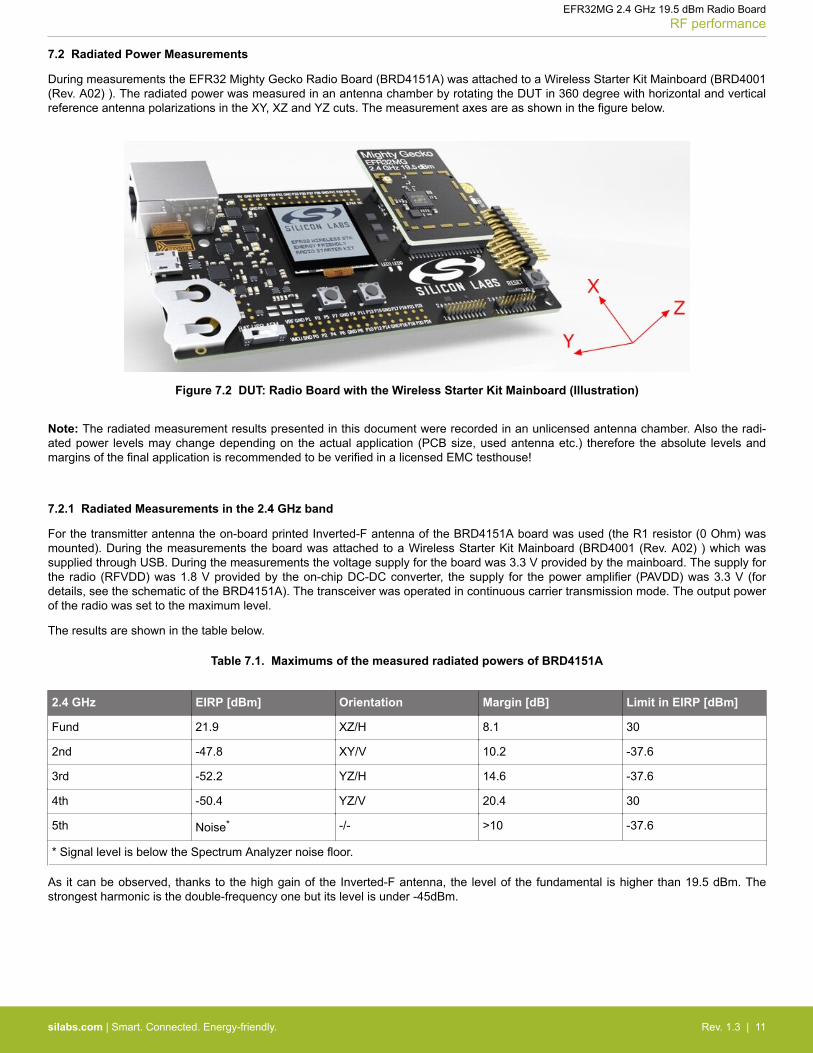
7.2 Radiated Power Measurements
During measurements the EFR32 Mighty Gecko Radio Board (BRD4151A) was attached to a Wireless Starter Kit Mainboard (BRD4001(Rev. A02) ). The radiated power was measured in an antenna chamber by rotating the DUT in 360 degree with horizontal and verticalreference antenna polarizations in the XY, XZ and YZ cuts. The measurement axes are as shown in the figure below.
Figure 7.2 DUT: Radio Board with the Wireless Starter Kit Mainboard (Illustration)
Note: The radiated measurement results presented in this document were recorded in an unlicensed antenna chamber. Also the radi-ated power levels may change depending on the actual application (PCB size, used antenna etc.) therefore the absolute levels andmargins of the final application is recommended to be verified in a licensed EMC testhouse!
7.2.1 Radiated Measurements in the 2.4 GHz band
For the transmitter antenna the on-board printed Inverted-F antenna of the BRD4151A board was used (the R1 resistor (0 Ohm) wasmounted). During the measurements the board was attached to a Wireless Starter Kit Mainboard (BRD4001 (Rev. A02) ) which wassupplied through USB. During the measurements the voltage supply for the board was 3.3 V provided by the mainboard. The supply forthe radio (RFVDD) was 1.8 V provided by the on-chip DC-DC converter, the supply for the power amplifier (PAVDD) was 3.3 V (fordetails, see the schematic of the BRD4151A). The transceiver was operated in continuous carrier transmission mode. The output powerof the radio was set to the maximum level.
The results are shown in the table below.
Table 7.1. Maximums of the measured radiated powers of BRD4151A
2.4 GHz EIRP [dBm] Orientation Margin [dB] Limit in EIRP [dBm]
Fund 21.9 XZ/H 8.1 30
2nd -47.8 XY/V 10.2 -37.6
3rd -52.2 YZ/H 14.6 -37.6
4th -50.4 YZ/V 20.4 30
5th Noise* -/- >10 -37.6
* Signal level is below the Spectrum Analyzer noise floor.
As it can be observed, thanks to the high gain of the Inverted-F antenna, the level of the fundamental is higher than 19.5 dBm. Thestrongest harmonic is the double-frequency one but its level is under -45dBm.
EFR32MG 2.4 GHz 19.5 dBm Radio BoardRF performance
silabs.com | Smart. Connected. Energy-friendly. Rev. 1.3 | 11

8. EMC Compliance Recommendations
8.1 Recommendations for 2.4 GHz ETSI EN 300-328 compliance
As it was shown in the previous chapter the radiated power of the fundamental of the EFR32 Mighty Gecko Radio Board (BRD4151A)complies with the 20 dBm limit of the ETSI EN 300-328 in case of the conducted measurement but due to the high antenna gain theradiated power is higher than the limit by 2 dB. In order to comply the output power should be reduced (with different antennas, depend-ing on the gain of the used antenna, the necessary reduction can be different). The harmonic emissions are under the -30 dBm limit.Although the BRD4151A Radio Board has an option for mounting a shielding can (P/N: Frame: BMI-S-203-F; Cover: BMI-S-203-C) thatis not required for the compliance.
8.2 Recommendations for 2.4 GHz FCC 15.247 compliance
As it was shown in the previous chapter the radiated power of the fundamental of the EFR32 Mighty Gecko Radio Board (BRD4151A)complies with the 30 dBm limit of the FCC 15.247. The harmonic emissions are under the -37.6 dBm applied limit both in case of theconducted and the radiated measurements. Although the BRD4151A Radio Board has an option for mounting a shielding can (P/N:Frame: BMI-S-203-F; Cover: BMI-S-203-C) that is not required for the compliance.
EFR32MG 2.4 GHz 19.5 dBm Radio BoardEMC Compliance Recommendations
silabs.com | Smart. Connected. Energy-friendly. Rev. 1.3 | 12

9. Revision History
Table 9.1. Document Revision History
Revision Num-ber
Effective Date Change Description
1.0 27.11.2015 Initial release.
1.1 12.12.2015 Updating Inverted-F Antenna Chapter and radiated measurement resultsbased on board revision B02.
1.2 28.01.2016 Fixing image render problem.
1.3 11.02.2016 Addign RF Section Power Supply chapter. Minor improvements.
EFR32MG 2.4 GHz 19.5 dBm Radio BoardRevision History
silabs.com | Smart. Connected. Energy-friendly. Rev. 1.3 | 13

10. Board Revisions
Table 10.1. BRD4151A Radio Board Revisions
Radio Board Revision Description
B01 Initial release
B02 Series component between the antenna and the matching output has been replaced with 0 Ohm resistor.Corrected silkscreen marking for the output power.
Note: The silkscreen marking on the board (e.g. PCBxxxx A00) denotes the revision of the PCB. The revision of the actual Radio Boardcan be read from the on-board EEPROM.
EFR32MG 2.4 GHz 19.5 dBm Radio BoardBoard Revisions
silabs.com | Smart. Connected. Energy-friendly. Rev. 1.3 | 14

11. Errata
Table 11.1. BRD4151A Radio Board Errata
Radio Board Revision Problem Description
B01 Incorrect silkscreenmarking.
Output power marked as "20 dBm" instead of "19.5 dBm."
Unnecessary componentmounted.
Power Amplifier settings have been optimized so the R1 resistor (0 Ohm) is notnecessary any more, 0 Ohm resistor can be used instead.
EFR32MG 2.4 GHz 19.5 dBm Radio BoardErrata
silabs.com | Smart. Connected. Energy-friendly. Rev. 1.3 | 15
Table of Contents
1. Radio Board Connector . . . . . . . . . . . . . . . . . . . . . . . . . . . 11.1 Introduction. . . . . . . . . . . . . . . . . . . . . . . . . . . . . . . 1
1.2 Radio Board Connector Pin Associations. . . . . . . . . . . . . . . . . . . . . 1
2. System-on-Chip Description . . . . . . . . . . . . . . . . . . . . . . . . . 22.1 Introduction. . . . . . . . . . . . . . . . . . . . . . . . . . . . . . . 2
2.2 System-on-Chip Block Diagram . . . . . . . . . . . . . . . . . . . . . . . . 2
2.3 System Summary . . . . . . . . . . . . . . . . . . . . . . . . . . . . 3
3. Radio Board Block Summary . . . . . . . . . . . . . . . . . . . . . . . . . 43.1 Introduction. . . . . . . . . . . . . . . . . . . . . . . . . . . . . . . 4
3.2 Radio Board Block Diagram . . . . . . . . . . . . . . . . . . . . . . . . . 4
3.3 Radio Board Block Description . . . . . . . . . . . . . . . . . . . . . . . . 43.3.1 LF Crystal Oscillator (LFXO) . . . . . . . . . . . . . . . . . . . . . . . . 43.3.2 HF Crystal Oscillator (HFXO) . . . . . . . . . . . . . . . . . . . . . . . . 43.3.3 Matching Network for 2.4 GHz. . . . . . . . . . . . . . . . . . . . . . . . 43.3.4 Inverted-F Antenna . . . . . . . . . . . . . . . . . . . . . . . . . . . 43.3.5 UFL Connector . . . . . . . . . . . . . . . . . . . . . . . . . . . . . 53.3.6 Radio Board Connector . . . . . . . . . . . . . . . . . . . . . . . . . . 5
4. RF Section . . . . . . . . . . . . . . . . . . . . . . . . . . . . . . . . 64.1 Introduction. . . . . . . . . . . . . . . . . . . . . . . . . . . . . . . 6
4.2 Schematic of the RF Matching Network . . . . . . . . . . . . . . . . . . . . . 64.2.1 Description of the 2.4 GHz RF Matching . . . . . . . . . . . . . . . . . . . . 6
4.3 RF Section Power Supply . . . . . . . . . . . . . . . . . . . . . . . . . . 6
4.4 Bill of Materials for the 2.4 GHz Matching . . . . . . . . . . . . . . . . . . . . 6
4.5 Inverted-F Antenna . . . . . . . . . . . . . . . . . . . . . . . . . . . . 7
5. Mechanical Details . . . . . . . . . . . . . . . . . . . . . . . . . . . . . 8
6. EMC Compliance . . . . . . . . . . . . . . . . . . . . . . . . . . . . . . 96.1 Introduction. . . . . . . . . . . . . . . . . . . . . . . . . . . . . . . 9
6.2 EMC Regulations for 2.4 GHz . . . . . . . . . . . . . . . . . . . . . . . . 96.2.1 ETSI EN 300-328 Emission Limits for the 2400-2483.5 MHz Band . . . . . . . . . . . 96.2.2 FCC15.247 Emission Limits for the 2400-2483.5 MHz Band. . . . . . . . . . . . . . 96.2.3 Applied Emission Limits for the 2.4 GHz Band . . . . . . . . . . . . . . . . . . 9
7. RF performance . . . . . . . . . . . . . . . . . . . . . . . . . . . . . 107.1 Conducted Power Measurements . . . . . . . . . . . . . . . . . . . . . . .107.1.1 Conducted Measurements in the 2.4 GHz band . . . . . . . . . . . . . . . . . .10
7.2 Radiated Power Measurements . . . . . . . . . . . . . . . . . . . . . . . .117.2.1 Radiated Measurements in the 2.4 GHz band . . . . . . . . . . . . . . . . . .11
8. EMC Compliance Recommendations . . . . . . . . . . . . . . . . . . . . . 128.1 Recommendations for 2.4 GHz ETSI EN 300-328 compliance . . . . . . . . . . . . .12
Table of Contents 16

8.2 Recommendations for 2.4 GHz FCC 15.247 compliance . . . . . . . . . . . . . . .12
9. Revision History . . . . . . . . . . . . . . . . . . . . . . . . . . . . . 13
10. Board Revisions. . . . . . . . . . . . . . . . . . . . . . . . . . . . . 14
11. Errata . . . . . . . . . . . . . . . . . . . . . . . . . . . . . . . . . 15
Table of Contents . . . . . . . . . . . . . . . . . . . . . . . . . . . . . . 16
Table of Contents 17

DisclaimerSilicon Laboratories intends to provide customers with the latest, accurate, and in-depth documentation of all peripherals and modules available for system and software implementers using or intending to use the Silicon Laboratories products. Characterization data, available modules and peripherals, memory sizes and memory addresses refer to each specific device, and "Typical" parameters provided can and do vary in different applications. Application examples described herein are for illustrative purposes only. Silicon Laboratories reserves the right to make changes without further notice and limitation to product information, specifications, and descriptions herein, and does not give warranties as to the accuracy or completeness of the included information. Silicon Laboratories shall have no liability for the consequences of use of the information supplied herein. This document does not imply or express copyright licenses granted hereunder to design or fabricate any integrated circuits. The products must not be used within any Life Support System without the specific written consent of Silicon Laboratories. A "Life Support System" is any product or system intended to support or sustain life and/or health, which, if it fails, can be reasonably expected to result in significant personal injury or death. Silicon Laboratories products are generally not intended for military applications. Silicon Laboratories products shall under no circumstances be used in weapons of mass destruction including (but not limited to) nuclear, biological or chemical weapons, or missiles capable of delivering such weapons.
Trademark InformationSilicon Laboratories Inc., Silicon Laboratories, Silicon Labs, SiLabs and the Silicon Labs logo, CMEMS®, EFM, EFM32, EFR, Energy Micro, Energy Micro logo and combinations thereof, "the world’s most energy friendly microcontrollers", Ember®, EZLink®, EZMac®, EZRadio®, EZRadioPRO®, DSPLL®, ISOmodem ®, Precision32®, ProSLIC®, SiPHY®, USBXpress® and others are trademarks or registered trademarks of Silicon Laboratories Inc. ARM, CORTEX, Cortex-M3 and THUMB are trademarks or registered trademarks of ARM Holdings. Keil is a registered trademark of ARM Limited. All other products or brand names mentioned herein are trademarks of their respective holders.
http://www.silabs.com
Silicon Laboratories Inc.400 West Cesar ChavezAustin, TX 78701USA
Simplicity StudioOne-click access to MCU tools, documentation, software, source code libraries & more. Available for Windows, Mac and Linux!
www.silabs.com/simplicity
MCU Portfoliowww.silabs.com/mcu
SW/HWwww.silabs.com/simplicity
Qualitywww.silabs.com/quality
Support and Communitycommunity.silabs.com