Embed Size (px)
Citation preview

Braswell POS Motherboard (with BIOS Setup) User Manual (Edition May 2018)

We would like to know your opinion on this publication. Please send us a copy of this page if you have any constructive criticism. We would like to thank you in advance for your comments. With kind regards,
Diebold Nixdorf Wohlrabedamm 31 D-13629 Berlin E-Mail: [email protected] Order No.: 01750305326A
Your opinion:

Braswell POS Motherboard User Manual
Edition May 2018

All brand and product names mentioned in this document are trademarks of their respective owners.
Copyright © Wincor Nixdorf International GmbH, 2018
The re production, transmission or use of this document or its contents is not permitted without ex-press authority. Offenders will be liable for damages. All rights, including rights created by patent
grant or registration of a utility model or design, are reserved. Delivery subject to availability; technical modifications possible.

Braswell POS Motherboard, User Manual 1
1 Overview............................................................................... 4 1.1 Introduction .............................................................................. 4 1.2 Highlights of O1.0-BSW-mITX Motherboard ............................ 4 1.3 Restriction of the O1.0 motherboard ....................................... 5
2 Motherboard Specification ................................................... 6 2.1 Function blocks of O1.0 motherboard ..................................... 6 2.2 Technical Specification and Motherboard Features summary . 7 2.3 Motherboard Mechanical Arrangement .................................. 9 2.4 Motherboard PCB Dimension ................................................. 10 2.5 External I/O Connector ........................................................... 10 2.6 Internal I/O Connector ........................................................... 11 2.7 Jumper setting ........................................................................ 11 2.8 Power consumption of Braswell O1.0 Motherboard ............. 12 2.9 Maximum current rating for external peripherals ................. 12
2.9.1 Supported power modes (Sx) ......................................... 13 2.10 Thermal management ............................................................ 13 2.11 CPU support ............................................................................ 13 2.12 Memory support .................................................................... 14 2.13 Graphics Subsystem ............................................................... 15 2.14 Gigabit Ethernet LAN Interface .............................................. 15 2.15 Super I/O Controller ............................................................... 16 2.16 SATA III Interface .................................................................... 16 2.17 CPU Fan and System Fans ....................................................... 16 2.18 Audio ...................................................................................... 17 2.19 USB Interface .......................................................................... 17 2.20 Serial Interfaces COM1-6 ........................................................ 18 2.21 Parallel Port ............................................................................ 18 2.22 PS/2 Keyboard Interface ......................................................... 18 2.23 Front Panel Interface .............................................................. 18 2.24 Cash Drawer Interface ............................................................ 19
2.24.1 Cash Drawer Interface (SM bus) ................................... 19 2.25 Intrusion Detect Interface ...................................................... 19 2.26 TPM ........................................................................................ 19 2.27 M.2 ......................................................................................... 19
3 Connector and Pin Assignments .......................................... 20 3.1 External Connectors ............................................................... 20
3.1.1 PS/2 Keyboard Connector ............................................... 20

2 Braswell POS Motherboard, User Manual
3.1.2 Gigabit Ethernet LAN Connector ..................................... 21 3.2 USB Connectors ...................................................................... 21
3.2.1 COM1-6 Connectors ........................................................ 22 3.2.2 VGA Connector ................................................................ 23 3.2.3 Audio Connector ............................................................. 24 3.2.4 LPT connector .................................................................. 25
3.3 Connectors and Headers for internal Connection .................. 26 3.3.1 SATA ................................................................................ 26 3.3.2 USB Header ..................................................................... 26 3.3.3 Front Panel Interface Connector ..................................... 27 3.3.4 Cash Drawer Interface Connector ................................... 27 3.3.5 Fan Connector (with PWM FAN Speed Control) ............. 28 3.3.6 Fan Connector (with DC FAN Speed Control) .................. 28 3.3.7 Intrusion Interface ........................................................... 28 3.3.8 ATX Power ....................................................................... 29
4 Changing the Battery ........................................................... 30
5 UEFI BIOS Setup .................................................................. 31 5.1 Standard UEFI BIOS Version .................................................... 31 5.2 BIOS Menu Bar ........................................................................ 32 5.3 Legend Screen ......................................................................... 33 5.4 General Help ........................................................................... 33 5.5 Scroll Bar ................................................................................. 33 5.6 Sub-Menu ............................................................................... 34
6 Info Screen .......................................................................... 35
7 Main Menu.......................................................................... 37
8 Advanced Menu .................................................................. 38 8.1 Realtek PCIe GBE Family Controller ........................................ 39 8.2 Trusted Computing ................................................................. 40 8.3 ACPI Settings ........................................................................... 42 8.4 CPU Configuration .................................................................. 43 8.5 PPM Configuration .................................................................. 44 8.6 SATA Configuration ................................................................. 45 8.7 AMI Graphic Output Protocol Policy ....................................... 46 8.8 SIO Configuration .................................................................... 47 8.9 USB Configuration ................................................................... 48 8.10 Platform Trust Technology ..................................................... 49

Braswell POS Motherboard, User Manual 3
9 Chipset Menu ...................................................................... 50 9.1 Intel IGD Configuration ........................................................... 51 9.2 Graphics Power Management Control ................................... 53 9.3 South bridge ........................................................................... 54
10 Hardware Monitor .............................................................. 55
11 Power ................................................................................. 56
12 Security ............................................................................... 58
13 Boot .................................................................................... 59 13.1 CSM Configuration.................................................................. 60 13.2 Network Stack Configuration ................................................. 61
14 Save & Exit .......................................................................... 62
15 Abbreviations...................................................................... 64

4 Braswell POS Motherboard, User Manual
1 Overview
1.1 Introduction
This specification describes the features of a motherboard based on the IN-TEL Braswell processor (SoC) in mITX form factor (O Series: O1.0-BSW-mITX 01750297809). This O Series Motherboard is designed for Diebold Nixdorf’s BEETLE /MIII, BEETLE /X plus and BEETLE moPOS PDH systems. This mainboard will be produced only as one assembling variant: “N3160”.
1.2 Highlights of O1.0-BSW-mITX Motherboard
Intel Celeron processor N3160 (quad core), base 1.6GHz, up to 2.24GHz
Integrated Intel HD Graphics 400
1x VGA (needs internal cable)
2x DVI (PL2)
HDD SATA III interface (1 port)
Fan-less motherboard design, but supports PSU (3 pin) and chassis fan (4 pin, with automatic PWM speed control)
1 Gigabit LAN
1 DDR3L SDRAM (SO-DIMM) socket, up to 8GB / 1600MHz supported
1 PCIe slot
M.2 slot, connected by SATA
6 COM port pin header (all ports have the option to be powered COM)
1 LPT port pin header

Braswell POS Motherboard, User Manual 5
1 PS/2 port
9 USB2 ports
2 USB3 ports
1 cash drawer port onboard
Intel HD audio controller with microphone, line in and line out
OS support Windows 7 (32 and 64 Bit), Windows 10 (64 Bit)
Long term availability for 5 years (Intel embedded roadmap)
1.3 Restriction of the O1.0 motherboard
No support for Game Port, FDD
No support for DOS and Win98 and XP
No audio amplifier onboard
no raid support
no AMT support
no support for displays without DDC

6 Braswell POS Motherboard, User Manual
2 Motherboard Specification
2.1 Function blocks of O1.0 motherboard
DDR3L CH0
DVI-D / PL2
(front out, line, mic)
VGG PCIE
VCCP0/1
VGA
USB2.0 1 To 7 HUB
DDI1
NCT6106D
DVI-D / PL2
W25Q32DW
PCIE
TPM HEADER
AZALIA
COMPATIBLE WITH USB2.0
DDI 0
DIMM0
PCIe x1 slot
VR12.1RT8171B
USB3.0 2 port
(not assembled)
SPI
Super I/O
(mainboard monitor)
ALC662/ALC892
LPC I/F
1PORTS
mPCIe slot
1 LPT
USB3.0
BRASWELL
m.2 SSD
DDR3 1600/10664G/8G
VR12.1RT8171B
PCIE
SATA
(BIOS)
NGFF
SATA3.0
USB2.0
(Graphic power)
AUDIO
DDI 2
eMMC
GIGABIT LANRTL8111GS
(Core power)
eMMC option
6 COMHEADER
and 4 port from SOC

Braswell POS Motherboard, User Manual 7
2.2 Technical Specification and Motherboard Features summary
Microprocessor Intel Celeron Processor N3160 (quad core), 1.6GHz
Supported Systems BEETLE /MIII, /X plus and BEETLE moPOS PDH
Architecture mITX form factor Chipset Braswell SoC, supporting SATA III con-
troller, USB UHCI, EHCI and XHCI con-troller, Interrupt controller, DMA con-troller, LPC interface, RTC, SMBUS host interface, PCIe, Intel High Defini-tion Audio interface, SPI
Super I/O NCT6106D, supporting 6 UARTS, PS/2 Keyboard and Mouse interface, LPT, automatic fan speed controller, hard-ware monitor
Ethernet Controller
PCI-e based Realtek RTL8111G 10/100/1000 MBit, PXE
Wake On Feature Wake On LAN, Wake On Time, Wake On USB, Wake On Keyboard (PS/2), Wake on Power Button
Sound Controller Audio Codec with Line-out, Line-in and Mic-in connectors in I/O shield
Cash Drawer onboard Cash Drawer controller, 6 pin JST connector for direct connection to cash drawer integrated in power supply
Main Memory 1x SO-DIMM, up to 8GB DDR3L SDRAM technology, based on up to 8Gb technology, unbuffered non-ECC running at 1600MHz
BIOS SPI Flash, 64Mb, AMI BIOS, with cus-tomization for BEETLE Systems, PnP 1.1, ACPI, DMI-support
Keyboard PS/2 connection onboard in I/O shield, supporting Y-cable for Mouse support

8 Braswell POS Motherboard, User Manual
Serial Interfaces COM1-6 onboard, pin header, pow-ered COM support
LPT onboard, pin header, supporting SPP, EPP, ECP
USB USB2.0, 6 ports: USB 1, 2 – 2 ports stacked connector, series A in I/O shield (together with PS/2), USB 3, 4 (USB1_FRONT) – internal 2x5 pin header (for front USB, green) USB 5, 6 (USB2_HUB, USB3_UPS) – in-ternal 2x5 pin header (uplink for pow-ered USB HUB and UPS) USB 7, 8 – used in conjunction with PanelLink Interface USB 9 (USB4_PSU) – 24V powered USB in PSU USB3.0, 2 ports stacked connector, se-ries A in I/O shield (together with LAN)
Status LEDs supports LED (ON, Standby, OFF, HDD), power button and buzzer (front panel connector)
mass storage 1 SATA III interface (3.0Gb/s), 1x M.2 interface (2280, key M, SATA only)
PCIe slot 1 slot PCIe x1, 2.0 Video out 2x DVI and PanelLink 2.0, 1x VGA Battery for RTC and Super-I/O, Type: CR2032,
220mAh Fuses Poly switches or similar protection de-
vices for powered COM, all external USB (2 ports sharing one fuse), PS/2, VGA, DVI, PanelLink2,
I/O shield connectors stacked USB and PS/2 Keyboard + Mouse, stacked USB3 and GigaBit LAN, DVI (PanelLink2), audio (MIC In, LINE in, Line-Out)

Braswell POS Motherboard, User Manual 9
Internal connectors 1x DDR3 SO-DIMM socket, 1x Internal SATA connector, 1x USB (2 ports each, green color), 2x USB (1 port each), 6x (powered) COM, 1x CPU fan, 1x PSU fan, front panel, cash drawer, intrusion detection, TPM, VGA, M.2, CMOS clear, password clear
Board Dimension 170.0mm x 170.0 mm
2.3 Motherboard Mechanical Arrangement

10 Braswell POS Motherboard, User Manual
2.4 Motherboard PCB Dimension
O1.0 motherboard follows mITX standard and therefore PCB mechanical dimension is 170mm by 170mm.
2.5 External I/O Connector
External I/O connector arrangement:
Interface Connector-Type
Keyboard, Mouse, USB 6 pin Mini Din + stacked dual USB2 series A
LAN, USB RJ45 Ethernet + stacked dual USB3 series A
DVI/PanelLink2 DVI-I
AUDIO 3,5 mm female
VGA Optional by cable, DSUB 15
LAN/USB3 AUDIO
DVI/PL2.0
K/M/USB
DVI/PL2.0
VGA

Braswell POS Motherboard, User Manual 11
2.6 Internal I/O Connector
Interface Connector-Type
DDR3 SODIMM 1pcs 204 pin micro edge connector
M.2 1x M.2 2280 connector, Key M
Hard disk (SATA) 1pcs 7 pin Standard SATA headers
Power supply ATX 20 pin power connector
USB1_FRONT 1pcs 2x5 pin headers, 2.54 mm, green
USB2_HUB, USB3_UPS 1pcs 2x5 pin headers, 2.54 mm, black
COM 1-6 6pcs 2x6 pin headers, 2.54mm
PSU FAN 1pcs 3 pin
CPU FAN 1pcs 4 pin
PCIe 1x standard PCIe x1 connector
TPM 2x7pin header, 2mm
Front panel 1pcs 2x6 pin header, 2.54mm
Chassis intrusion 1pcs 3 pins header (2.0mm shrouded)
Cash drawer (incl. 24V pUSB) 1pcs 6 pins header (2.0mm shrouded)
2.7 Jumper setting
Jumper Connector-Type Setting
JP1 Password clear 1-2 password clear
JP2 CMOS clear 1-2 CMOS clear

12 Braswell POS Motherboard, User Manual
2.8 Power consumption of Braswell O1.0 Motherboard
O1.0 motherboard is powered by 3.3V, 5V, 5Vstby, 12V and -12V from a standard ATX power supply. The maximum current is specified as follows, this does not include external connected peripherals.
Voltage I max P
3.3V 0.45A 1.5W
5V 0.5A 2.5W
5VSB 1A 5W
12V 1.5A 18W
-12V 0.2A 2.4W
2.9 Maximum current rating for external peripherals
Interface Voltage I max
Powered COM (COM 1-6 summary) 5V 1A
Powered COM single port 5V 0.3A
Powered COM (COM 1-6 summary) 12V 1A
Powered COM single port 12V 0.6A
USB2, single port 5V 0.5A
USB3, single port 5V 0.9A
USB, all ports summary 5V 3A
Keyboard 5V 0.5A
VGA 5V 0.1A
Braswell POS Motherboard, User Manual 13
2.9.1 Supported power modes (Sx)
O1.0 Motherboard supports power states S0, S3, S4 and S5. Wake up events from sleep states are supported from USB ports, internal CMOS clock, PS2 Keyboard, power button and Ethernet. Power management supports ACPI 3.0 and APM1.2 Following power-on events from S4 and S5 are defined (if enabled in BIOS):
Power button
LAN
RMT via PanelLink2 interface
Internal clock
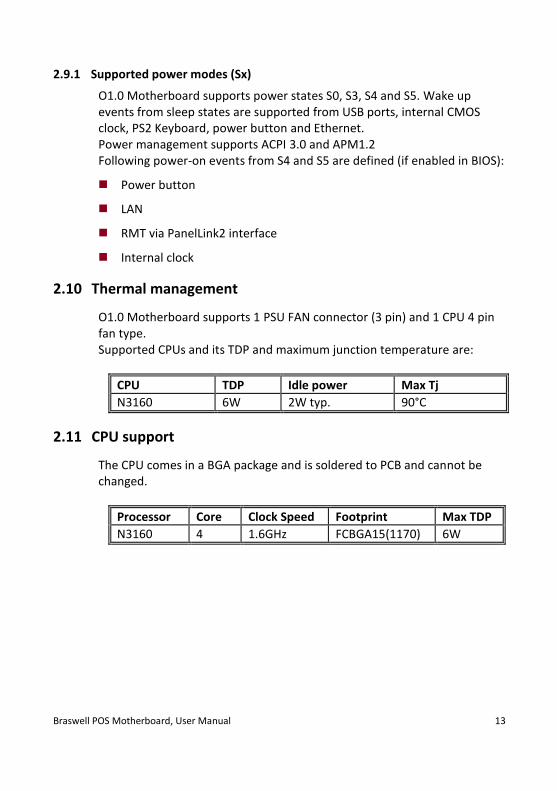
2.10 Thermal management
O1.0 Motherboard supports 1 PSU FAN connector (3 pin) and 1 CPU 4 pin fan type. Supported CPUs and its TDP and maximum junction temperature are:
CPU TDP Idle power Max Tj
N3160 6W 2W typ. 90°C
2.11 CPU support
The CPU comes in a BGA package and is soldered to PCB and cannot be changed.
Processor Core Clock Speed Footprint Max TDP
N3160 4 1.6GHz FCBGA15(1170) 6W

14 Braswell POS Motherboard, User Manual
2.12 Memory support
The motherboard has one SO-DIMM socket supporting single channel, un-buffered, no ECC DDR3L SDRAM. Memory size of 1GB, 2GB, 4GB and 8GB.
DIMM Capacity DRAM DEVICE TECHNOLOGY DRAM ORGANIZATION
1 GB 1 Gb X8
2 GB 2 Gb X8
4 GB 4 Gb X8
8 GB 8 Gb X8
1 GB 2 Gb X16
2 GB 4 Gb X16
4 GB 8 Gb X16
The motherboard supports the following memory features:
1066 / 1600 MHz unbuffered SDRAM SO-DIMM
Non-ECC
1.35V voltage rating (DDR3L)
BIOS automatically detects memory type, size, and speed If 1333MHz memory modules are used, the frequency will be limited to 1066MHz automatically.

Braswell POS Motherboard, User Manual 15
2.13 Graphics Subsystem
Graphic support of internal graphics accelerator of the N3160 processor to provide 3 independent displays. Main features of integrated GPU are:
Gen 8-LP Intel® graphics core, HD Graphics 400
320Mhz render clock, up to 640Mhz during burst, 12 execution units
DirectX12, OpenGL 4.2
Intel® Clear Video HD Technology
Intel® Quick Sync Video
Intel® InTru™ 3D Technology The analogue VGA port, based on IT6515 eDP to VGA bridge, capable of driving a standard progressive scan monitor resolution up to 1920x1200@60Hz
SIGNAL VOLTAGE LEVEL
R,G,B 0.7VP-P @75OHM
HSYNC, VSYNC 5.0V
DDC CHANNEL OPEN DRAIN, 5.0V TOLERANT
2.14 Gigabit Ethernet LAN Interface
Gigabit Ethernet LAN interface is provided thru a PCI-e based Ethernet Controller made by Realtek RTL8111G.

16 Braswell POS Motherboard, User Manual
2.15 Super I/O Controller
Super I/O controller NCT6106D from Nuvoton provides the following func-tions:
6 16C550 UARTs
PS/2 Keyboard and Mouse controller
Two Automatic Fan Speed controller
Two tachometer inputs
Hardware monitor
The hardware monitor uses the following resistor dividers for
12V: 110k/10k (factor 12)
5V: 40.2k/10k (factor 5)
2.16 SATA III Interface
The CPU has two integrated SATA ports that support data transfer rates up to 6.0Gb/s.
SATA Port USAGE ON MOTHERBOARD
Port #0 ON-BOARD CONNECTOR
Port #1 M.2
2.17 CPU Fan and System Fans
O1.0 motherboard supports automatic fan speed control by pulse width modulation (PWM) and by DC control. If a 3 pin fan (DC control) is used in BEETLE/MIII as PSU fan with no rpm control and read-back. The 2nd CPU fan (4 pin, PWM control) can be used in BEETLE moPOS PDH.

Braswell POS Motherboard, User Manual 17
2.18 Audio
An INTEL HD Audio Link is provided by the Braswell N3160 SoC. It is used with a Realtek HD Audio Codec ALC662 providing a low cost solution. In case of EOL the ALC892 is prepared for AVL use. Supported interfaces are:
Line-out
Mic-in
Line-in
2.19 USB Interface
The Braswell SoC N3160 contains one XHCI compliant host controller that supports USB super-, high-, full- and low-speed signalling.
XHCI Port Connection on Motherboard
0 Upper USB/LAN connector in IO shield
1 Lower USB/LAN connector in IO shield
2 Uplink to onboard USB hub chip
3 Upper USB/PS2 connector in IO shield
4 Lower USB/PS2 connector in IO shield
Hub port 0 Uplink to powered USB hub
Hub port 1 USB3_UPS connector
Hub port 2 PanelLink 1
Hub port 3 PanelLink 2
Hub port 4 Front USB (upper) (USB1_FRONT)
Hub port 5 Front USB (lower) (USB1_FRONT)
Hub port 6 24V powered USB port in PSU (USB4_PSU)

18 Braswell POS Motherboard, User Manual
2.20 Serial Interfaces COM1-6
O1.0 motherboard provides six serial ports. All ports are routed to pin headers ready to be used as powered (female, incl. 5V and 12V, max cur-rent for powered COM: single port 300mA@5V; all ports together not more than 1A@5V; single port 600mA@12V; all ports together not more than 1A@12V) or standard COM (male). This selection is done by using dif-ferent internal cables. In case of powered serial ports (COM*) the signals RI and DCD are ex-changed with system voltage of +5V and +12V. These serial ports are routed to 2x6 pin headers (2.54mm) and via cables to DSUB-9 connectors. All serial ports comply with RS-232 signalling level voltage. Maximum voltage drop on 12V is 300mV, on 5V it is 150mV at full load. This output is designed according to UL regulations and is protected by a self-resettable fuse.
2.21 Parallel Port
O1.0 motherboard supports a parallel port according to IEEE1284.
2.22 PS/2 Keyboard Interface
The keyboard controller is part of the Super I/O chip. The PS/2 keyboard interface is available on a Mini DIN connector.
2.23 Front Panel Interface
The motherboard provides a front panel interface, supporting the following features:
Power ON/OFF button
Reset button
Status LED, showing Active (Green, S0), Standby (Green, flashing, S3), Shutdown (orange, S4 and S5, HDD Activity (Amber, flashing)
System beeper

Braswell POS Motherboard, User Manual 19
2.24 Cash Drawer Interface
2.24.1 Cash Drawer Interface (SM bus)
This Cash Drawer interface is provided by a 6pin shrouded header. From this header a cable goes to the power supply where the cash drawer out-put is located. The cash drawer function is equivalent to Diebold Nixdorf iPOS+ Braswell. It is based on NCT5605Y SM bus to GPIO bridge chip. GP20 is used as CD output (a falling edge initiate a 250ms active cash drawer signal) while GP21 is used as status input.
2.25 Intrusion Detect Interface
O1.0 motherboard supports an intrusion detect interface connected to the Super IO. The intrusion monitoring is used to protect the system against unauthor-ized opening of the chassis. This intrusion is detected even if no AC is ap-plied. However, this will not be indicated until the system is operating again. Type: 3 pin shrouded header, B3B-PH-K-S (JST) or equivalent.
2.26 TPM
O1.0 motherboard is prepared for Infineon TPM module. This feature is provided by a dual row 14 pin header pitch 2mm.
2.27 M.2
The M.2 connector supports M.2 Key M modules with SATA of 2280. M.2 PCIe based modules are not supported.
20 Braswell POS Motherboard, User Manual
3 Connector and Pin Assignments
3.1 External Connectors
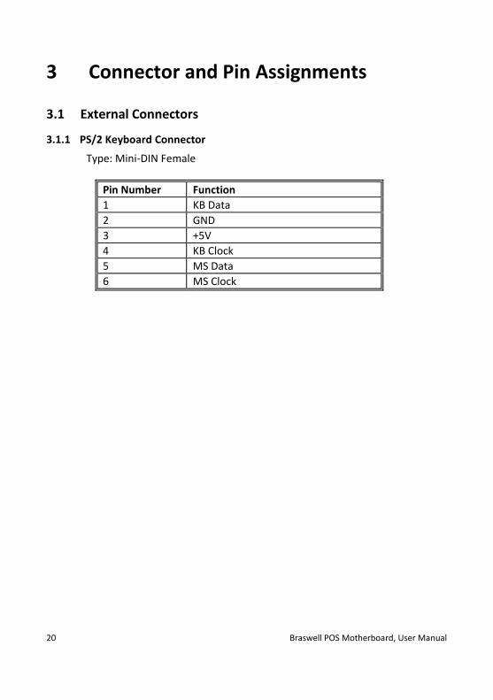
3.1.1 PS/2 Keyboard Connector
Type: Mini-DIN Female
Pin Number Function
1 KB Data
2 GND
3 +5V
4 KB Clock
5 MS Data
6 MS Clock

Braswell POS Motherboard, User Manual 21
3.1.2 Gigabit Ethernet LAN Connector
Type: RJ45 connector. (Stacked LAN + USB Connector)
Pin Number Function
1 TP0+
2 TP0-
3 TP1+
4 TP2+
5 TP2-
6 TP1-
7 TP3+
8 TP3-
3.2 USB Connectors
Type: Stacked USB Type A Connector, Male (Stacked LAN + USB Connector)
Pin Number Function
1 Fused +5V
2 USB D-
3 USB D+
4 GND

22 Braswell POS Motherboard, User Manual
3.2.1 COM1-6 Connectors
Type: 2x 6 pin header, 2.54 mm pitch
Pin Number Function
1 DCD
2 RXD
3 TXD
4 DTR
5 GND
6 DSR
7 RTS
8 CTS
9 RI
10 Key
11 +5V
12 +12V

Braswell POS Motherboard, User Manual 23
3.2.2 VGA Connector
Type: on the motherboard 2x 6 pin header, 2.54 mm pitch
Pin Number Function
1 DDC CLK
2 DDC DATA
3 +5V
4 VSYNC
5 HSYNC
6 GND
7 Red
8 GND
9 Green
10 GND
11 Blue
12 GND
behind the cable: type DSUB-15 pin, DSUB-15 Female
Pin Number Function
1 RED
2 GREEN
3 BLUE
4 n.c.
5 GND
6 GND
7 GND
8 GND
9 +5V
10 GND
11 n.c.
12 DDC SDA
13 HSYNC
14 VSYNC
15 DDC SCL

24 Braswell POS Motherboard, User Manual
3.2.3 Audio Connector
Type: Stacked Audio Jack
Port Number Function
Top Line in
Middle Line out
Bottom Microphone In

Braswell POS Motherboard, User Manual 25
3.2.4 LPT connector
Pin Number Function
1 /STROBE
2 /AUTOFD Autofeed
3 D0 Data Bit 0
4 /ERROR Error
5 D1 Data Bit 1
6 /INIT Initialize
7 D2 Data Bit 2
8 /SELIN Select In
9 D3 Data Bit 3
10 GND
11 D4 Data Bit 4
12 GND
13 D5 Data Bit 5
14 GND
15 D6 Data Bit 6
16 GND
17 D7 Data Bit 7
18 GND
19 /ACK Acknowledge
20 GND
21 Busy
22 GND
23 PE Paper End
24 GND
25 SEL Select
26 key

26 Braswell POS Motherboard, User Manual
3.3 Connectors and Headers for internal Connection
3.3.1 SATA
Type: 7 pin SATA connector, LD180F-S16P (Foxconn) or equivalent.
Pin Number Function
1 GND
2 TXP
3 TXN
4 GND
5 RXN
6 RXP
7 GND
3.3.2 USB Header
Type: 2x5 pin headers, 2.54mm pitch.
Pin Number Function
1 +5V
2 +5V
3 D-
4 D-
5 D+
6 D+
7 GND
8 GND
9 Key
10 nc
Braswell POS Motherboard, User Manual 27
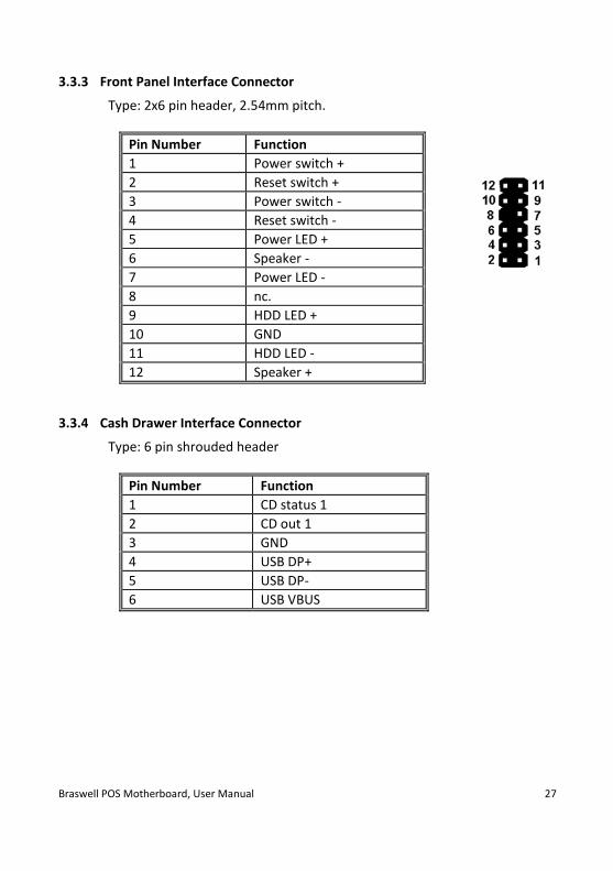
3.3.3 Front Panel Interface Connector
Type: 2x6 pin header, 2.54mm pitch.
Pin Number Function
1 Power switch +
2 Reset switch +
3 Power switch -
4 Reset switch -
5 Power LED +
6 Speaker -
7 Power LED -
8 nc.
9 HDD LED +
10 GND
11 HDD LED -
12 Speaker +
3.3.4 Cash Drawer Interface Connector
Type: 6 pin shrouded header
Pin Number Function
1 CD status 1
2 CD out 1
3 GND
4 USB DP+
5 USB DP-
6 USB VBUS

28 Braswell POS Motherboard, User Manual
3.3.5 Fan Connector (with PWM FAN Speed Control)
Type: 4 pin connector with Friction Lock, vertical.
Pin Number Function
1 GND
2 +12V
3 FAN RPM
4 FAN PWM
3.3.6 Fan Connector (with DC FAN Speed Control)
Pin Signal
1 GND
2 PWR
3 Sense
3.3.7 Intrusion Interface
Type: 3 pin shrouded header, B3B-PH-K-S (JST) or equivalent.
Pin Number Function
1 GND
2 Intrusion input
3 n.c.

Braswell POS Motherboard, User Manual 29
3.3.8 ATX Power
Pin Number Function
1,2,11 +3.3V
3,5,7,13,16,16,17 GND
4,6,19,20 +5V
8 Power ok
9 5V SB
10 +12V
12 -12V
14 PSON

30 Braswell POS Motherboard, User Manual
4 Changing the Battery
The systems are equipped with a lithium battery on the motherboard to ensure data retention, the time and the setup parameters. The battery should be changed approximately every five years.
When inserting the new battery, make sure the polarity is correct. This is marked in the socket. Incorrect replacement of the battery may lead to the danger of explosion.
The battery is located in a socket on the Motherboard. To gain access to the battery, proceed as described in the according chapters of your BEETLE User Manual.
The lithium battery must be replaced only by identical batteries or types recommended by Diebold Nixdorf International.
You can return the used batteries to your Diebold Nixdorf International sales outlet. Batteries containing harmful substances are marked accordingly. The chemical denotations are as follows: CD = Cadmium; Pb = Lead, Li = Lithium.
This symbol on a battery tells you that batteries containing harmful substances must not be disposed of as household waste. Follow the country specific laws and regulations. Within the European Union you are legally bound to return these batteries to the service organization where you purchased the new battery.
The setup parameters must be reset each time the battery has been changed.

Braswell POS Motherboard, User Manual 31
5 UEFI BIOS Setup
The mainboard comes with an AMI UEFI BIOS chip that contains the ROM Setup information of your system. This chip serves as an interface between the processor and the rest of the mainboard’s components. This section explains the information contained in the Setup program and tells you how to modify the settings according to your system configuration. Even if you are not prompted to use the Setup program, you might want to change the configuration of your system in the future. For example, you may want to enable the Security Password Feature or make changes to the power management settings. It will then be necessary to reconfigure your system using the BIOS Setup program so that the system can recognize these changes and record them in the NVRAM. All setup data is stored in a non-volatile memory (NVRAM). When you remove the battery, all settings, except the BIOS password, are set to default.
5.1 Standard UEFI BIOS Version
The UEFI BIOS ROM of the system holds the Setup utility. When you turn on the system, it will provide you with the opportunity to run this program. This appears during the Power-On Self-Test (POST). Press <F2> or click setup in the upper right corner to call the Setup utility. If you missed the opportunity to pressing the mentioned key, POST will continue with its test routines, thus preventing you from calling Setup. If you still need to call Setup, reset the system by pressing <Ctrl> + <Alt> + <Del>. You can also re-start by turning the system off and then on again. But do so only if the first method fails. If you like to change the boot order only once, you can press the <F10> key or click on BBS in the upper right corner during the POST is running. At the end you will see a Pop-Up window with all the devices the system has found. With the keys <UP> and <DOWN> you select the boot device. The Setup program has been designed to make it as easy as possible. It is a menu-driven program, which means you can scroll through the various sub-menus and make your selections among the predetermined choices.

32 Braswell POS Motherboard, User Manual
You can also use the mouse or the touch screen to navigate through the menus. When you invoke Setup, the main program screen will appear. Read more about the Setup entries on the following pages. Because the UEFI BIOS software is constantly being updated, the following UEFI BIOS screens and descriptions are for reference purposes only and may not reflect your UEFI BIOS screens exactly.
5.2 BIOS Menu Bar
Press the ON/OFF button until a beep is emitted. Press then the F2 button to start the BIOS menu. The top of the screen has a menu bar with the following sections:
Info Use this menu for information only
Main Use this menu to make changes to the basic system configuration.
Advanced Use this menu to enable and make changes to the ad-vanced features.
Security Use this menu to enable a supervisor or user password and Intrusion Detection.
Power Use this menu to configure the chipset specific options
Event Logs Use this menu to change the Smbios Log configuration.
Boot Use this menu to configure the default system device used to locate and load the Operating System.
Save & Exit Use this menu to exit the current menu or specify how to exit the Setup program.
To access the menu bar items, press the right or left arrow key on the keyboard until the desired item is highlighted.

Braswell POS Motherboard, User Manual 33
5.3 Legend Screen
The right frame displays the key legend. The keys in the legend frame allow you to navigate through the various setup menus. The following table lists the keys found in the legend with their corresponding alternates and functions.
Navigation Key(s) Description of Functions
or (keypad ar-rows)
Select the menu item to the left or right.
or (keypad arrows) Moves the highlight up or down between fields.
Enter Move into sub menu or change selected menu items
+ (plus key) - (minus key)
Change field contents.
<Tab> Jumps from one field to the next.
<F1> Opens a general Help Screen with extended information.
<F2> Load previous values (Load last saved values)
<F3> Load optimized values (Factory reset)
<F4> Saves changes and exits Setup.
<Esc> Opens a windows to select between exit and return to setup
5.4 General Help
In addition to the Item Specific Help window, the UEFI BIOS setup program also provides a General Help screen. This screen can be called from any menu by simply pressing <F1>. The General Help screen lists the legend keys with their corresponding alternates and functions.
5.5 Scroll Bar
When a scroll bar appears to the right of a help window, it indicates that there is more information to be displayed that will not fit in the window. Use <PgUp> and <PgDn> or the up and down keys to scroll through the en-tire help document.

34 Braswell POS Motherboard, User Manual
Press <Home> to display the first page, press <End> to reach the last page. To exit the help window, press the <Enter> or <Esc> key.
5.6 Sub-Menu
Note that a right pointer symbol “” appears left of certain fields. This pointer indicates that a sub-menu can be launched from this field. A sub-menu contains additional options for a field parame-ter.
To call a sub-menu, simply move the highlight to the field and press <En-ter>. The sub-menu then will appear immediately. Use the legend keys to enter values and move from field to field within a sub-menu just as you would do within a menu. Use the <Esc> key to return to the main menu. Take some time to familiarize yourself with each of the legend keys and their corresponding functions. Practice navigating through the various menus and sub-menus. If you accidentally make unwanted changes to any of the fields, use the set default hot key <F3>. While moving around through the Setup program, note that explanations appear in the Item Spe-cific Help window located to the right side of each menu. This window dis-plays the help text for the currently highlighted field.

Braswell POS Motherboard, User Manual 35
6 Info Screen
When the Setup program is accessed, the following info screen appears:
This screen is for information only. There is nothing that could be changed within Setup. All information is intended to facilitate the support of your system. Product Name This text is fixed for your mainboard with standard UEFI BIOS. BIOS Revision The UEFI BIOS version is displayed in the format WN STD xx/yy
xx Core Version, never changes
yy Release Version, changes with every update
zz Internal Release, for tests only
The UEFI BIOS Date is displayed the date of release in international format: MM/DD/YYYY

36 Braswell POS Motherboard, User Manual
Ethernet MAC-Address The Ethernet MAC-Address of the on board LAN Controller is displayed at this line if this device is enabled. UUID Info A UUID is an identifier standard used in software construction, standard-ized by the Open Software Foundation. The intent of UUIDs is to enable distributed systems to uniquely identify information without significant central coordination. System, Mainboard, Power Supply The default placeholders may be replaced by specific data from factory, describing configuration, serial number etc. for each device.

Braswell POS Motherboard, User Manual 37
7 Main Menu
The Main Menu is entered, to determine the basic system configuration and to provide an overview. Some of the parameters are only available un-der certain conditions.
System date Set the date. Use Tab to switch between date elements. Default ranges: Year: 2005-2099 Days: dependent on month System time Set the time. Use Tab to switch between time elements.

38 Braswell POS Motherboard, User Manual
8 Advanced Menu
The advanced functions which are available to the system are configured in this menu for the advanced system configuration. Only change the default settings if required for a special purpose. Incorrect settings can cause malfunctions.

Braswell POS Motherboard, User Manual 39
8.1 Realtek PCIe GBE Family Controller
Get driver information about the Realtek Controller.

40 Braswell POS Motherboard, User Manual
8.2 Trusted Computing
Security Device Support [Enabled] Enables or disables BIOS support for security device. O.S. will not show se-curity device. TCG EFI protocol and INT1A interface will not be available. SHA-1 PCR Bank [Enabled] Enable or disable SHA-1 PCR Bank. SMA256 PCR Bank [Disabled] Enable or disable SMA256 PCR. Pending Operation [None] Option: [TPM Clear]. Schedule an operation for the security device. Note: Your computer will reboot during restart in order to change state of secu-rity device. Platform Hierarchy [Enabled] Enable or disable platform hierarchy. Storage Hierarchy [Enabled] Enable or disable storage hierarchy.

Braswell POS Motherboard, User Manual 41
Endorsement Hierarchy [Enabled] Enable or disable endorsement hierarchy. TPM2.0 UEFI Spec Version [Enabled] Select the TCG2 spec version support. TCG_1.2: the compatible mode for WIN8/WIN10. TCG_2.0: support new TCG2 protocol and event format for Win10 or later. Physical Presence Spec Version [TCG.2] Select to tell O.S. to support PP1 spec version 1.2 or 1.3. Note some HCK tests might not support 1.3. Device Select [Auto] TPM 1.2 will restrict support to TPM 1.2 devices. TPM 2.0 will restrict sup-port to TPM 2.0 devices. Auto will support both with the default set to TPM 2.0 devices if not found, TPM 1.2 devces will be enumerated.

42 Braswell POS Motherboard, User Manual
8.3 ACPI Settings
Enable ACPI Auto Configuration [Disabled] Enables or disables BIOS ACPI auto configuration. Enable Hibernation [Enabled] Enables or disables system ability to hibernate (OS/S4 sleep state). This op-tion may be not effective with some OS. ACPI Sleep State [S3 (Suspend to RAM)] Select the highest ACPI sleep state the system will enter when the SUS-PEND button is pressed. Function can be disabled. LOCK Legacy Resources [Disabled] Enables or disables lock of legacy resources.

Braswell POS Motherboard, User Manual 43
8.4 CPU Configuration
Opens the CPU Configuration submenu. Some of the parameters are only available under certain conditions.
Socket 0 CPU information Socket specific CPU information CPU Thermal Configuration Enable or disable DTS. Limit CPUID Maximum [Disabled] Disabled for Windows XP. Intel Virtualization Maximum [Enabled] When enabled a VMM can utilize the additional hardware capabilities pro-vided by Vanderpool Technology. Power Technology [Energy Efficient] Enable the power management features. Options: Disabled and Custom.

44 Braswell POS Motherboard, User Manual
8.5 PPM Configuration
EIST [Enabled] Enable or disable Intel SpeedStep CPU C state report [Enabled] Enable or Disable CPU C state report to OS. Max CPU C-state [C7] This option controls Max C state that the processor will support. Option: C6 and C1. SOix [Disabled] Enable or disable CPU SOix state.

Braswell POS Motherboard, User Manual 45
8.6 SATA Configuration
SATA Controller [Enabled] Enable or disable SATA device Harddisk Pre Delay [3 sec] Choose different times. SATA Interface Speed [Gen3] Select SATA interface speed. CHV A1 always with Gen1 speed. Option: Gen1 and Gen2. Aggressive LPM Support [Enabled] Enable PCH to aggressively enter link power state. Port 0 [Enabled] Enable or disable SATA port. Port 1 [Enabled] Enable or disable SATA port.

46 Braswell POS Motherboard, User Manual
Spin Up Device [Disabled] If enable for any ports staggered spin up will be performed and only the drives which have this option enabled will spin up to boot. Otherwise all drives spin up at boot. Device Sleep Support [Disabled] Enable or disable this function.
8.7 AMI Graphic Output Protocol Policy
Output Select [EDP1] No choice available. Brightness Settings [255] Set the brightness settings. BIST Enable [Disabled] Starts or stops the BIST on the integrated display panel.

Braswell POS Motherboard, User Manual 47
8.8 SIO Configuration
View and set basic properties of the SIO logical device as IO bas, IRQ range DMA channel and device mode in this menu. Enable or disable the serial ports.

48 Braswell POS Motherboard, User Manual
8.9 USB Configuration
Legacy USB Support [Enabled] Enables legacy USB support. AUTO option disables legacy support if no USB devices are connected. DISABLE option will keep USB devices available only for EFI applications. XHCI Hand-off [Enabled] This is a workaround for operating systems without XHCI hand-off support. The XHCI ownership change should be claimed by XHCI driver. USB Mass Storage Driver Support [Enabled] Enable or disable USB mass storage driver support. Port 60/64 Emulation [Enabled] Enables I/O port 60h/64h emulation support. This should ne enables for the complete USB keyboard legacy support for non USB aware operating systems. USB transfer time-out [20 sec] The time-out value for control, bulk and internet transfers. Device reset time-out [20 sec] USB mass storage device start unit command time-out

Braswell POS Motherboard, User Manual 49
Device power-up delay [Auto] Maximum time the device will take before it properly reports itself to the most controller. AUTO uses default value: for a root port it is 100 ms. For a hub port the delay is taken from hub descriptor.
8.10 Platform Trust Technology
fTPM [Disabled] Enable or disable the Firmware TPM here.

50 Braswell POS Motherboard, User Manual
9 Chipset Menu

Braswell POS Motherboard, User Manual 51
9.1 Intel IGD Configuration
Internal Graphics Port Order [VGA>Display.1>Display.2] Select which device may be used as primary display. Options: [Display.1>Display.2>VGA] [VGA>Display.2>Display.1] [Display.2>Display.1>VGA] [Display.1> VGA>Display.2] [Display.2> VGA>Display.1] IGD Turbo [Auto] Select the IGD Turbo feature if AUTO is selected. IGD Turbo will only be en-abled when SOC stepping is BO or above. Options: Enable and Disable. Primary Display [Auto] Select which of IGD/PCI graphics device should be primary display. GFX Boost [Disabled] Enable or disable GFX boost. PAVC [Enabled] Enable or disable the protected audio video control.
52 Braswell POS Motherboard, User Manual
DVMT Pre-Allocated [32M] Select DVMT 5.0 pre allocated (fixed) graphics memory size used by the in-ternal graphics device. Options: 32M – 512M. DVMT Total Gfx Mem [256MB] Select DVMT 5.0 total graphics memory size used by the internal graphics device. Options: 128MB, 256MB and Max. Aperture Size [256MB] Fix. GTT Size [4MB] Select the GTT size. Options: 2MB, 4MB and 8MB.

Braswell POS Motherboard, User Manual 53
9.2 Graphics Power Management Control
RC6 (Render Standby) [Disabled] Check to enable render standby support. Power Meter Lock [Enabled] Enable or disable power meter lock.

54 Braswell POS Motherboard, User Manual
9.3 South bridge
Security Configuration Set the parameter for the security configuration. Azalia Configuration Azalia HD Audio options. USB Configuration USB configuration settings. Serial IRQ Mode Configure the serial IRQ mode.
Braswell POS Motherboard, User Manual 55
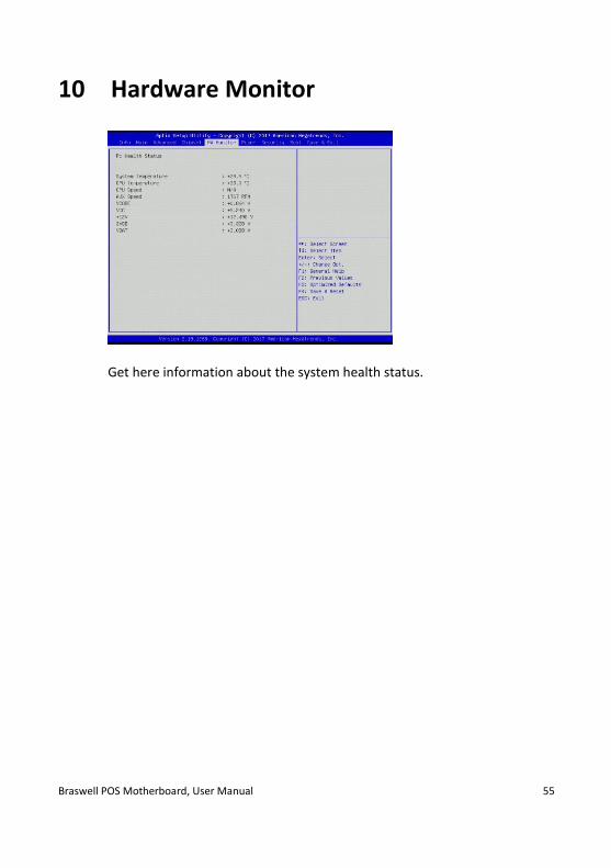
10 Hardware Monitor
Get here information about the system health status.

56 Braswell POS Motherboard, User Manual
11 Power
Enable ACPI Auto Configuration [Disabled] Enable or disable the BIOS ACPI auto configuration Enable Hibernation [Enabled] Enable or disable system ability to hibernate (OS/S4 sleep state). This op-tion may be not effective with some operating systems. ACPI Sleep State [S3 (Suspend to RAM)] Select the highest ACPI sleep state the system will enter when the SUSPEND button is pressed. Can be disabled. Lock Legacy Resources [Disabled] Enable or disable lock of legacy resources. Deep Sleep SS support [Disabled] Enable or disable the deep sleep SS function. Onboard PCIE LAN Device [Enabled] Control the PCI Express root port. LAN Wakeup support [Disabled] Disable or enable the LAN wake up function.

Braswell POS Motherboard, User Manual 57
Wake Up on Alarm [Disabled] Enable or disable system wake up on alarm event. When enabled, system will wake on the hr::min::sec specified. USB/PS2 S3 Wake up [Disabled] Enable or disable the USB/PS2 S3 wake up. USB/PS2 S4 Wake up [Disabled] Enable or disable the USB/PS2 S4 wake up. Restore AC Power Loss [Power Off] Select AC power state when power is re-applied after a power failure. Options: Follow AC Power and Last State. RMT1 Support [Disabled] This is used for DVI1 RMT Support. RMT2 Support [Disabled] This is used for DVI2 RMT Support.

58 Braswell POS Motherboard, User Manual
12 Security
Clear Password Jumper [Enabled] Can disable the password clear jumper. Intrusion detection [Disabled] Enable or disable the intrusion detection. Secure Boot [Custom] Customizable secure boot settings. Option: Standard
Braswell POS Motherboard, User Manual 59
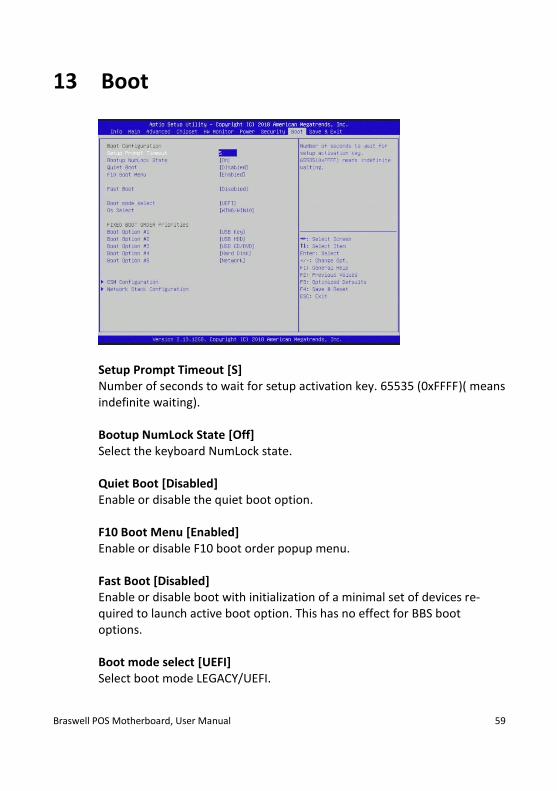
13 Boot
Setup Prompt Timeout [S] Number of seconds to wait for setup activation key. 65535 (0xFFFF)( means indefinite waiting). Bootup NumLock State [Off] Select the keyboard NumLock state. Quiet Boot [Disabled] Enable or disable the quiet boot option. F10 Boot Menu [Enabled] Enable or disable F10 boot order popup menu. Fast Boot [Disabled] Enable or disable boot with initialization of a minimal set of devices re-quired to launch active boot option. This has no effect for BBS boot options. Boot mode select [UEFI] Select boot mode LEGACY/UEFI.

60 Braswell POS Motherboard, User Manual
OS Select [Win8/Win10] Select the operation system type.
Win7: LPSS device is in PCI mode, which will adapt to PCI mode OS driver.
Win8/win10: LPSS device is in ACPI mode, which will adapt to APCI mode OS driver.
Other: Consist with customer OS requirement (e.g. WNLPOS) Current setting is for PCI mode.
Boot option Set the system boot order in this menu.
13.1 CSM Configuration
CSM Support [Enabled] Setting may not be changed. HDD Connection Order [Adjust] Adjust or keep the HDD configuration. Launch PXE Option Rom [UEFI] Configuration options: [Do not launch], [UEFI], [Legacy]

Braswell POS Motherboard, User Manual 61
Storage Configuration options: [Do not launch], [UEFI], [Legacy] Video Configuration options: [Do not launch], [UEFI], [Legacy] Other PCI devices Configuration options: [Do not launch], [UEFI], [Legacy]
13.2 Network Stack Configuration
Network Stack [Enabled] Enable or disable UEFI network stack. Ipv4 PXE Support [Enabled] Enable here Ipv4 PXE boot support. If disabled Ipv4 PXE boot an option will not be created. Ipv6 PXE Support [Enabled] Enable here Ipv6 PXE boot support. If disabled Ipv6 PXE boot an option will not be created. PXE boot wait time [0] Wait time to press ESC key to abort the PXE boot. Media detect count [1] Number of times presence of media will be checked.

62 Braswell POS Motherboard, User Manual
14 Save & Exit
Save Changes and Reset Reset the system after saving the changes. Discard Changes and Exit Exit system setup without saving any change. Discard Change and Reset Reset system setup without saving any change. Save Changes Save changes done so far to any of setup options. Discard Changes Discard changes done so far to any of setup options.

Braswell POS Motherboard, User Manual 63
Restore Defaults Restore/Load default values for all the setup options. Save as User Defaults Save changes done so far as user defaults. Restore User defaults Restore the user defaults to all the setup options.

64 Braswell POS Motherboard, User Manual
15 Abbreviations
ADM AMI Display Manager ACPI Advanced Configuration and Power Interface AGTL+ Assisted Gunning Transceiver Logic APC Advanced Power Control APIC Advanced Peripheral Interrupt Controller APM Advanced Power Management AT Advanced Technology ATA AT Attachment BAT Basic Access Test BBS BIOS Boot Specification BDA BIOS Data Area BGA Ball Grid Array BIOS Basic Input and Output System CMOS Complementary Metal Oxide Semiconductor CPLD Complex Programmable Logic Device CPU Central Processing Unit CRT Cathode-ray Tube DIM Device Initialization Manager DIMM Dual Inline Memory Module DMA Direct Memory Access DMI Desktop Management Interface DVMT Dynamic Video Memory Technology DVI Digital Video Interface EBDA Extended BIOS Data Area ECP Extended Capabilities Port EEPROM Electrical Erasable Read Only Memory EFI Extensible Firmware Interface E-IDE Enhanced Integrated Drive Electronics EMS Expanded Memory System ESCD Extended System Configuration Data EPP Enhanced Parallel Port FSB Front Side Bus

Braswell POS Motherboard, User Manual 65
GPNV General Purpose Non-Volatile (RAM) GTL Gunning Transceiver Logic HW Hardware IDE Integrated Drive Electronics IGD Internal Graphic Device IPL Initial Program Load (Device) LAN Local Area Network LBA Logical Block Addressing LCD Liquid Crystal Display MAC Media Access Control MTRR Memory Type Range Register MP Multiple Processors NA Power failure NVRAM Non-volatile Random Access Memory P-ATA Parallel AT Attachment (old version of hard disk inter-
face) POS Point of Sales PCI Peripheral Component Interconnect PnP Plug and Play POST Power On Self Test RAM Random Accessible Memory RI Ring Indicator ROM Read Only Memory RS Retail Systems SATA Serial AT Attachment (new version of hard disk interface) SLP System Locked Pre-Installation SMI System Management Interrupt SMM System Management Mode SMRAM System Management RAM SPGA Staggered Pin Grid Array

66 Braswell POS Motherboard, User Manual
TFT Thin-film transistor TPM Trusted Platform Module UEFI Unified Extensible Firmware Interface UPS Uninterruptible Power Supply USB Universal Serial Bus UUID Universal Unique Identifier VGA Video Graphics Array WOL Wake On LAN WOM Wake On Modem

Diebold Nixdorf D-33094 Paderborn Order No.: 01750305326A