Embed Size (px)
DESCRIPTION
Electrical
Citation preview

Branch current methodThe first and most straightforward network analysis technique is called the Branch Current Method. In this method, we assume directions of currents in a network, then write equations describing their relationships to each other through Kirchhoff's and Ohm's Laws. Once we have one equation for every unknown current, we can solve the simultaneous equations and determine all currents, and therefore all voltage drops in the network.Let's use this circuit to illustrate the method:
The first step is to choose a node (junction of wires) in the circuit to use as a point of reference for our unknown currents. I'll choose the node joining the right of R1, the top of R2, and the left of R3.
At this node, guess which directions the three wires' currents take, labeling the three currents as I1, I2, and I3, respectively. Bear in mind that these directions of current are speculative at this point. Fortunately, if it turns out that any of our guesses were wrong, we will know when we mathematically solve for the currents (any “wrong” current directions will show up as negative numbers in our solution).
Kirchhoff's Current Law (KCL) tells us that the algebraic sum of currents entering and exiting a node must equal zero, so we can relate these three currents (I1, I2, and I3) to each other in a single equation. For the sake of convention, I'll denote any current entering the node as positive in sign, and any current exiting the node as negative in sign:

The next step is to label all voltage drop polarities across resistors according to the assumed directions of the currents. Remember that the “upstream” end of a resistor will always be negative, and the “downstream” end of a resistor positive with respect to each other, since electrons are negatively charged:
The battery polarities, of course, remain as they were according to their symbology (short end negative, long end positive). It is OK if the polarity of a resistor's voltage drop doesn't match with the polarity of the nearest battery, so long as the resistor voltage polarity is correctly based on the assumed direction of current through it. In some cases we may discover that current will be forced backwards through a battery, causing this very effect. The important thing to remember here is to base all your resistor polarities and subsequent calculations on the directions of current(s) initially assumed. As stated earlier, if your assumption happens to be incorrect, it will be apparent once the equations have been solved (by means of a negative solution). The magnitude of the solution, however, will still be correct.Kirchhoff's Voltage Law (KVL) tells us that the algebraic sum of all voltages in a loop must equal zero, so we can create more equations with current terms (I1, I2, and I3) for our simultaneous equations. To obtain a KVL equation, we must tally voltage drops in a loop of the circuit, as though we were measuring with a real voltmeter. I'll choose to trace the left loop of this circuit first, starting from the upper-left corner and moving counter-clockwise (the choice of starting points and directions is arbitrary). The result will look like this:

Having completed our trace of the left loop, we add these voltage indications together for a sum of zero:
Of course, we don't yet know what the voltage is across R1 or R2, so we can't insert those values into the equation as numerical figures at this point. However, we do know that all three voltages must algebraically add to zero, so the equation is true. We can go a step further and express the unknown voltages as the product of the corresponding unknown currents (I1 and I2) and their respective resistors, following Ohm's Law (E=IR), as well as eliminate the 0 term:
Since we know what the values of all the resistors are in ohms, we can just substitute those figures into the equation to simplify things a bit:

You might be wondering why we went through all the trouble of manipulating this equation from its initial form (-28 + ER2 + ER1). After all, the last two terms are still unknown, so what advantage is there to expressing them in terms of unknown voltages or as unknown currents (multiplied by resistances)? The purpose in doing this is to get the KVL equation expressed using the same unknown variables as the KCL equation, for this is a necessary requirement for any simultaneous equation solution method. To solve for three unknown currents (I1, I2, and I3), we must have three equations relating these three currents (not voltages!) together.Applying the same steps to the right loop of the circuit (starting at the chosen node and moving counter-clockwise), we get another KVL equation:

Knowing now that the voltage across each resistor can be and should be expressed as the product of the corresponding current and the (known) resistance of each resistor, we can re-write the equation as such:
Now we have a mathematical system of three equations (one KCL equation and two KVL equations) and three unknowns:
For some methods of solution (especially any method involving a calculator), it is helpful to express each unknown term in each equation, with any constant value to the right of the equal sign, and with any “unity” terms expressed with an explicit coefficient of 1. Re-writing the equations again, we have:
Using whatever solution techniques are available to us, we should arrive at a solution for the three unknown current values:

So, I1 is 5 amps, I2 is 4 amps, and I3 is a negative 1 amp. But what does “negative” current mean? In this case, it means that our assumed direction for I3 was opposite of its realdirection. Going back to our original circuit, we can re-draw the current arrow for I3 (and re-draw the polarity of R3's voltage drop to match):
Notice how current is being pushed backwards through battery 2 (electrons flowing “up”) due to the higher voltage of battery 1 (whose current is pointed “down” as it normally would)! Despite the fact that battery B2's polarity is trying to push electrons down in that branch of the circuit, electrons are being forced backwards through it due to the superior voltage of battery B1. Does this mean that the stronger battery will always “win” and the weaker battery always get current forced through it backwards? No! It actually depends on both the batteries' relative voltages and the resistor values in the circuit. The only sure way to determine what's going on is to take the time to mathematically analyze the network.Now that we know the magnitude of all currents in this circuit, we can calculate voltage drops across all resistors with Ohm's Law (E=IR):
Let us now analyze this network using SPICE to verify our voltage figures.[spi] We could analyze current as well with SPICE, but since that requires the insertion of extra components into the circuit, and because we know that if the voltages are all the same and all the resistances are the same, the currents must all be the same, I'll opt for the less complex analysis. Here's a re-drawing of our circuit, complete with node numbers for SPICE to reference:
network analysis example v1 1 0 v2 3 0 dc 7

r1 1 2 4 r2 2 0 2r3 2 3 1.dc v1 28 28 1 .print dc v(1,2) v(2,0) v(2,3) .end v1 v(1,2) v(2) v(2,3) 2.800E+01 2.000E+01 8.000E+00 1.000E+00
The Mesh Current Method, also known as the Loop Current Method, is quite similar to the Branch Current method in that it uses simultaneous equations, Kirchhoff's Voltage Law, and Ohm's Law to determine unknown currents in a network. It differs from the Branch Current method in that it does not use Kirchhoff's Current Law, and it is usually able to solve a circuit with less unknown variables and less simultaneous equations, which is especially nice if you're forced to solve without a calculator.Mesh Current, conventional methodLet's see how this method works on the same example problem:
The first step in the Mesh Current method is to identify “loops” within the circuit encompassing all components. In our example circuit, the loop formed by B1, R1, and R2 will be the first while the loop formed by B2, R2, and R3 will be the second. The strangest part of the Mesh Current method is envisioning circulating currents in each of the loops. In fact, this method gets its name from the idea of these currents meshing together between loops like sets of spinning gears:
The choice of each current's direction is entirely arbitrary, just as in the Branch Current method, but the resulting equations are easier to solve if the currents are going the same direction through intersecting components (note how currents I1 and I2 are both going “up” through resistor R2, where they “mesh,” or intersect). If the assumed direction of a mesh current is wrong, the answer for that current will have a negative value.The next step is to label all voltage drop polarities across resistors according to the assumed directions of the mesh currents. Remember that the “upstream” end of a resistor will always be negative, and the “downstream” end of a resistor positive with respect to each other, since electrons are negatively charged. The battery polarities, of course, are dictated by their symbol orientations in the diagram, and may or may not “agree” with the resistor polarities (assumed current directions):

Using Kirchhoff's Voltage Law, we can now step around each of these loops, generating equations representative of the component voltage drops and polarities. As with the Branch Current method, we will denote a resistor's voltage drop as the product of the resistance (in ohms) and its respective mesh current (that quantity being unknown at this point). Where two currents mesh together, we will write that term in the equation with resistor current being the sum of the two meshing currents.Tracing the left loop of the circuit, starting from the upper-left corner and moving counter-clockwise (the choice of starting points and directions is ultimately irrelevant), counting polarity as if we had a voltmeter in hand, red lead on the point ahead and black lead on the point behind, we get this equation:
Notice that the middle term of the equation uses the sum of mesh currents I1 and I2 as the current through resistor R2. This is because mesh currents I1 and I2 are going the same direction through R2, and thus complement each other. Distributing the coefficient of 2 to the I1 and I2 terms, and then combining I1 terms in the equation, we can simplify as such:
At this time we have one equation with two unknowns. To be able to solve for two unknown mesh currents, we must have two equations. If we trace the other loop of the circuit, we can obtain another KVL equation and have enough data to solve for the two currents. Creature of habit that I am, I'll start at the upper-left hand corner of the right loop and trace counter-clockwise:
Simplifying the equation as before, we end up with:
Now, with two equations, we can use one of several methods to mathematically solve for the unknown currents I1 and I2:

Knowing that these solutions are values for mesh currents, not branch currents, we must go back to our diagram to see how they fit together to give currents through all components:
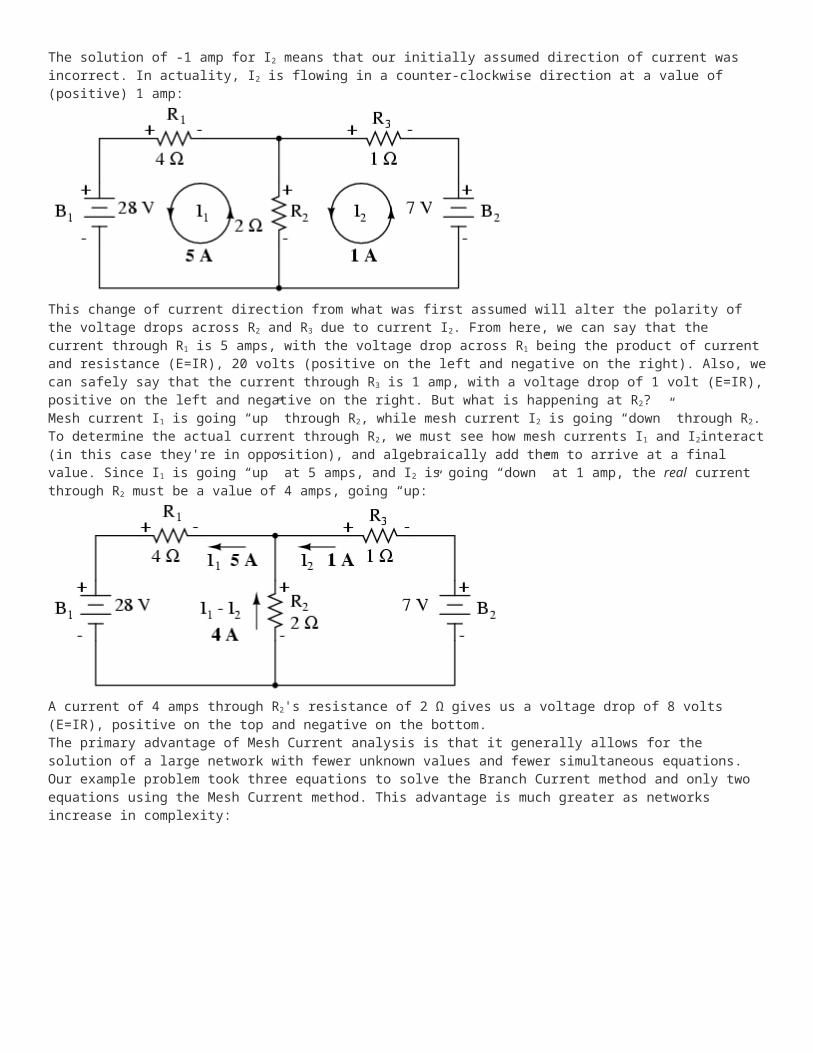
The solution of -1 amp for I2 means that our initially assumed direction of current was incorrect. In actuality, I2 is flowing in a counter-clockwise direction at a value of (positive) 1 amp:
This change of current direction from what was first assumed will alter the polarity of the voltage drops across R2 and R3 due to current I2. From here, we can say that the current through R1 is 5 amps, with the voltage drop across R1 being the product of current and resistance (E=IR), 20 volts (positive on the left and negative on the right). Also, we can safely say that the current through R3 is 1 amp, with a voltage drop of 1 volt (E=IR), positive on the left and negative on the right. But what is happening at R2?Mesh current I1 is going “up” through R2, while mesh current I2 is going “down” through R2. To determine the actual current through R2, we must see how mesh currents I1 and I2interact (in this case they're in opposition), and algebraically add them to arrive at a final value. Since I1 is going “up” at 5 amps, and I2 is going “down” at 1 amp, the real current through R2 must be a value of 4 amps, going “up:”

A current of 4 amps through R2's resistance of 2 Ω gives us a voltage drop of 8 volts (E=IR), positive on the top and negative on the bottom.The primary advantage of Mesh Current analysis is that it generally allows for the solution of a large network with fewer unknown values and fewer simultaneous equations. Our example problem took three equations to solve the Branch Current method and only two equations using the Mesh Current method. This advantage is much greater as networks increase in complexity:
To solve this network using Branch Currents, we'd have to establish five variables to account for each and every unique current in the circuit (I1 through I5). This would require five equations for solution, in the form of two KCL equations and three KVL equations (two equations for KCL at the nodes, and three equations for KVL in each loop):
I suppose if you have nothing better to do with your time than to solve for five unknown variables with five equations, you might not mind using the Branch Current method of analysis for this circuit. For those of us who have better things to do with our time, the Mesh Current method is a whole lot easier, requiring only three unknowns and three equations to solve:
Less equations to work with is a decided advantage, especially when performing simultaneous equation solution by hand (without a calculator).Another type of circuit that lends itself well to Mesh Current is the unbalanced Wheatstone Bridge. Take this circuit, for example:
Since the ratios of R1/R4 and R2/R5 are unequal, we know that there will be voltage across resistor R3, and some amount of current through it. As discussed at the beginning of this chapter, this type of circuit is irreducible by normal series-parallel analysis, and may only be analyzed by some other method.We could apply the Branch Current method to this circuit, but it would require six currents (I1 through I6), leading to a very large set of simultaneous equations to solve. Using the Mesh Current method, though, we may solve for all currents and voltages with much fewer variables.The first step in the Mesh Current method is to draw just enough mesh currents to account for all components in the circuit. Looking at our bridge circuit, it should be obvious where to place two of these currents:

The directions of these mesh currents, of course, is arbitrary. However, two mesh currents is not enough in this circuit, because neither I1 nor I2 goes through the battery. So, we must add a third mesh current, I3:
Here, I have chosen I3 to loop from the bottom side of the battery, through R4, through R1, and back to the top side of the battery. This is not the only path I could have chosen for I3, but it seems the simplest.Now, we must label the resistor voltage drop polarities, following each of the assumed currents' directions:

Notice something very important here: at resistor R4, the polarities for the respective mesh currents do not agree. This is because those mesh currents (I2 and I3) are going through R4 in different directions. This does not preclude the use of the Mesh Current method of analysis, but it does complicate it a bit. Though later, we will show how to avoid the R4current clash. (See Example below)Generating a KVL equation for the top loop of the bridge, starting from the top node and tracing in a clockwise direction:
In this equation, we represent the common directions of currents by their sums through common resistors. For example, resistor R3, with a value of 100 Ω, has its voltage drop represented in the above KVL equation by the expression 100(I1 + I2), since both currents I1 and I2 go through R3 from right to left. The same may be said for resistor R1, with its voltage drop expression shown as 150(I1 + I3), since both I1 and I3 go from bottom to top through that resistor, and thus work together to generate its voltage drop.Generating a KVL equation for the bottom loop of the bridge will not be so easy, since we have two currents going against each other through resistor R4. Here is how I do it (starting at the right-hand node, and tracing counter-clockwise):
Note how the second term in the equation's original form has resistor R4's value of 300 Ω multiplied by the difference between I2 and I3 (I2 - I3). This is how we represent the combined effect of two mesh currents going in opposite directions through the same component. Choosing the appropriate mathematical signs is very important here: 300(I2 - I3) does not mean the same thing as 300(I3 - I2). I chose to write 300(I2 - I3) because I was thinking first of I2's effect (creating a positive voltage drop, measuring with an imaginary voltmeter across R4, red lead on the bottom and black lead on the top), and secondarily of I3's effect (creating a negative voltage drop, red lead on the bottom and black lead on the top). If I had thought in terms of I3's effect first and I2's effect secondarily, holding my imaginary voltmeter leads in the same positions (red on bottom and black on top), the expression would have been -300(I3 - I2). Note that this expression is mathematically equivalent to the first one: +300(I2 - I3).Well, that takes care of two equations, but I still need a third equation to complete my simultaneous equation set of three variables, three equations. This third equation must also include the battery's voltage, which up to this point does not appear in either two of the previous KVL equations. To generate this equation, I will trace a loop again with my imaginary voltmeter starting from the battery's bottom (negative) terminal, stepping clockwise (again, the direction in which I step is arbitrary, and does not need to be the same as the direction of the mesh current in that loop):

Solving for I1, I2, and I3 using whatever simultaneous equation method we prefer:
Example:Use Octave to find the solution for I1, I2, and I3 from the above simplified form of equations. [octav]Solution:In Octave, an open source Matlab® clone, enter the coefficients into the A matrix between square brackets with column elements comma separated, and rows semicolon separated.[octav] Enter the voltages into the column vector: b. The unknown currents: I1, I2, and I3 are calculated by the command: x=A\b. These are contained within the x column vector. octave:1>A = [300,100,150;100,650,-300;-150,300,-450] A = 300 100 150 100 650 -300 -150 300 -450 octave:2> b = [0;0;-24] b = 0 0 -24 octave:3> x = A\b x = -0.093793 0.077241 0.136092The negative value arrived at for I1 tells us that the assumed direction for that mesh current was incorrect. Thus, the actual current values through each resistor is as such:

Calculating voltage drops across each resistor:
A SPICE simulation confirms the accuracy of our voltage calculations:[spi]

unbalanced wheatstone bridge v1 1 0 r1 1 2 150 r2 1 3 50 r3 2 3 100 r4 2 0 300 r5 3 0 250 .dc v1 24 24 1 .print dc v(1,2) v(1,3) v(3,2) v(2,0) v(3,0) .end
v1 v(1,2) v(1,3) v(3,2) v(2) v(3) 2.400E+01 6.345E+00 4.690E+00 1.655E+00 1.766E+01 1.931E+01Example:(a) Find a new path for current I3 that does not produce a conflicting polarity on any resistor compared to I1 or I2. R4 was the offending component. (b) Find values for I1, I2, and I3. (c) Find the five resistor currents and compare to the previous values.Solution: [dvn](a) Route I3 through R5, R3 and R1 as shown:

Note that the conflicting polarity on R4 has been removed. Moreover, none of the other resistors have conflicting polarities.(b) Octave, an open source (free) matlab clone, yields a mesh current vector at “x”:[octav] octave:1> A = [300,100,250;100,650,350;-250,-350,-500] A = 300 100 250 100 650 350 -250 -350 -500 octave:2> b = [0;0;-24] b = 0 0 -24 octave:3> x = A\b x = -0.093793 -0.058851 0.136092Not all currents I1, I2, and I3 are the same (I2) as the previous bridge because of different loop paths However, the resistor currents compare to the previous values: IR1 = I1 + I3 = -93.793 ma + 136.092 ma = 42.299 ma IR2 = I1 = -93.793 ma IR3 = I1 + I2 + I3 = -93.793 ma -58.851 ma + 136.092 ma = -16.552 ma IR4 = I2 = -58.851 ma IR5 = I2 + I3 = -58.851 ma + 136.092 ma = 77.241 ma
Superposition theorem is one of those strokes of genius that takes a complex subject and simplifies it in a way that makes perfect sense. A theorem like Millman's certainly works well, but it is not quite obvious why it works so well. Superposition, on the other hand, is obvious.The strategy used in the Superposition Theorem is to eliminate all but one source of power within a network at a time, using series/parallel analysis to determine voltage drops (and/or currents) within the modified network for each power source separately. Then, once voltage drops and/or currents have been determined for each power source working separately, the values are all “superimposed” on top of each other (added algebraically) to find the actual voltage drops/currents with all sources active. Let's look at our example circuit again and apply Superposition Theorem to it:
Since we have two sources of power in this circuit, we will have to calculate two sets of values for voltage drops and/or currents, one for the circuit with only the 28 volt battery in effect. . .
. . . and one for the circuit with only the 7 volt battery in effect:

When re-drawing the circuit for series/parallel analysis with one source, all other voltage sources are replaced by wires (shorts), and all current sources with open circuits (breaks). Since we only have voltage sources (batteries) in our example circuit, we will replace every inactive source during analysis with a wire.Analyzing the circuit with only the 28 volt battery, we obtain the following values for voltage and current:
Analyzing the circuit with only the 7 volt battery, we obtain another set of values for voltage and current:

When superimposing these values of voltage and current, we have to be very careful to consider polarity (voltage drop) and direction (electron flow), as the values have to be addedalgebraically.
Applying these superimposed voltage figures to the circuit, the end result looks something like this:
Currents add up algebraically as well, and can either be superimposed as done with the resistor voltage drops, or simply calculated from the final voltage drops and respective resistances (I=E/R). Either way, the answers will be the same. Here I will show the superposition method applied to current:

Once again applying these superimposed figures to our circuit:
Quite simple and elegant, don't you think? It must be noted, though, that the Superposition Theorem works only for circuits that are reducible to series/parallel combinations for each of the power sources at a time (thus, this theorem is useless for analyzing an unbalanced bridge circuit), and it only works where the underlying equations are linear (no mathematical powers or roots). The requisite of linearity means that Superposition Theorem is only applicable for determining voltage and current, not power!!! Power dissipations, being nonlinear functions, do not algebraically add to an accurate total when only one source is considered at a time. The need for linearity also means this Theorem cannot be applied in circuits where the resistance of a component changes with voltage or current. Hence, networks containing components like lamps (incandescent or gas-discharge) or varistors could not be analyzed.Another prerequisite for Superposition Theorem is that all components must be “bilateral,” meaning that they behave the same with electrons flowing either direction through them. Resistors have no polarity-specific behavior, and so the circuits we've been studying so far all meet this criterion.The Superposition Theorem finds use in the study of alternating current (AC) circuits, and semiconductor (amplifier) circuits, where sometimes AC is often mixed (superimposed) with DC. Because AC voltage and current equations (Ohm's Law) are linear just like DC, we can use Superposition to analyze the circuit with just the DC power source, then just the AC power source, combining the results to tell what will happen with both AC and DC sources in effect. For now, though, Superposition will suffice as a break from having to do simultaneous equations to analyze a circuit.