Embed Size (px)
Citation preview
BRAKE CONTROL – VEHICLE STABILITY CONTROL SYSTEM BC–1
BC
VEHICLE STABILITY CONTROL SYSTEMPRECAUTION1. TROUBLESHOOTING PRECAUTION
• When there are malfunctions in the contact points of the terminals or installation problems with any parts, removal and installation of the suspected problem parts may return the system to its normal condition either entirely or temporarily.
• In order to determine the location of the malfunction, be sure to check the conditions at the time the malfunction occurred through data such as DTC and freeze frame data outputs. Record this information before disconnecting any connectors and removing or installing any parts.
• Since the vehicle stability control system may be influenced by malfunctions in other systems, be sure to check for DTCs in other systems.
• Be sure to remove and install the ABS and TRACTION actuator and each sensor with the ignition switch OFF, unless specified in the inspection procedures.
• When removing and installing the ABS and TRACTION actuator and each sensor, be sure to check that the normal display is output during a test mode inspection and a DTC output inspection after reinstalling all the parts.
• After replacing the ABS and TRACTION actuator and/or yaw rate sensor, be sure to perform yaw rate and deceleration sensor zero point calibration (see page BC-24).
• The CAN communication system is used for data communication between the skid control ECU, the steering sensor and the yaw rate sensor (the deceleration sensor is included). If there is trouble in the CAN communication line, the DTC of the communication line is output.
• If the DTC of the CAN communication line is output, repair the malfunction in the communication line and then troubleshoot the vehicle stability control system.
• Since the CAN communication line has its own length and route, it cannot be repaired temporarily with a bypass wire, etc.

BC–2 BRAKE CONTROL – VEHICLE STABILITY CONTROL SYSTEM
BC
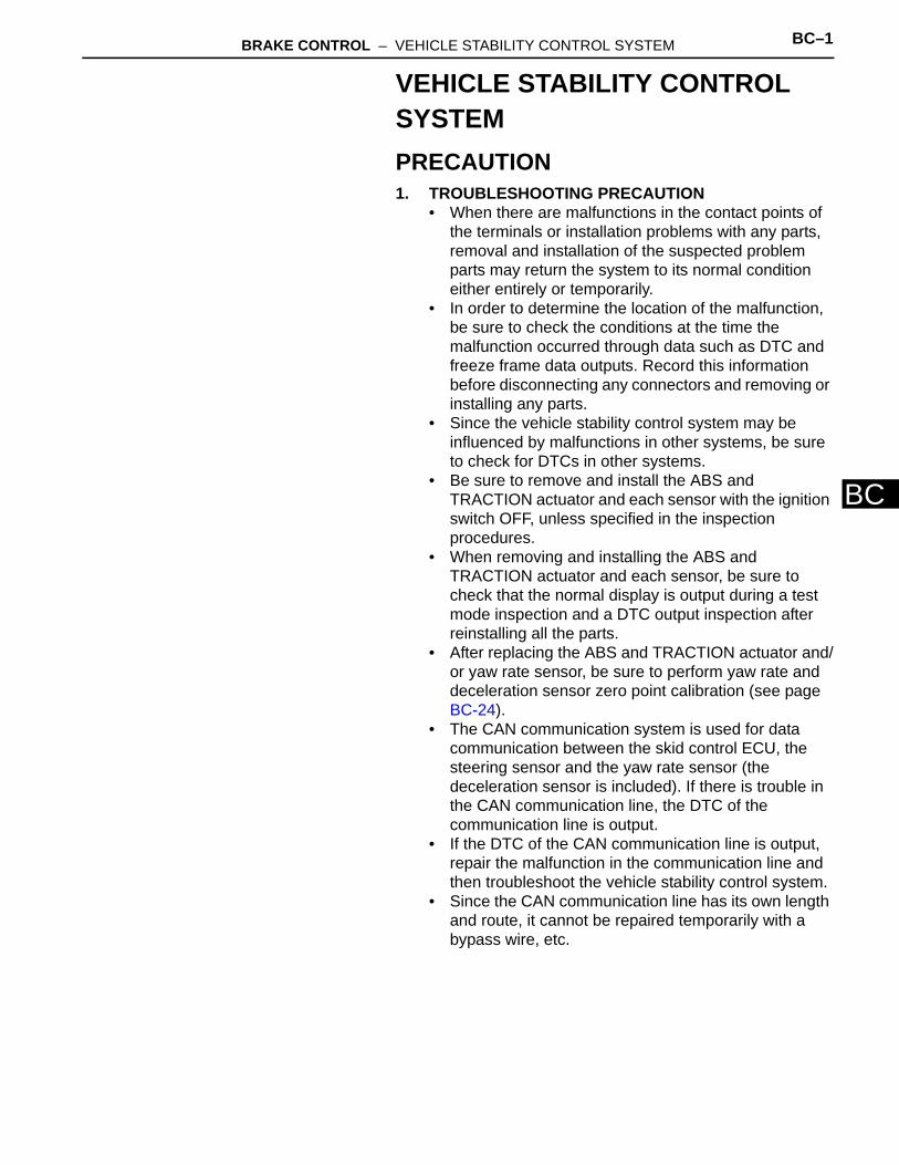
PARTS LOCATION
FRONT SPEED SENSOR ROTOR LH
FRONT SPEED SENSOR ROTOR RH
ECM
BRAKE ACTUATOR(SKID CONTROL ECU)
REAR SPEED SENSOR ROTOR RH REAR SPEED
SENSOR ROTOR LH
ENGINE ROOM NO. 1 RELAY BLOCK, ENGINE ROOM NO. 1 JUNCTION BLOCK- STOP LIGHT CONTROL Relay (Marking: BRK)- VSC MOTOR Relay (Marking: VSC MTR)- FAIL-SAFE Relay (Marking: VSC FAIL)- ABS1 H-FUSE- ABS2 H-FUSE
for 2WD
SKID CONTROL SENSOR ROTOR RH
SKID CONTROL SENSOR ROTOR LH
FRONT SPEED SENSOR RH
FRONT SPEED SENSOR LH
REAR SPEED SENSOR RH
REAR SPEED SENSOR LH
SKID CONTROL SENSOR LH
SKID CONTROL SENSOR RH
MASTER CYLINDER RESERVOIR- BRAKE FLUID LEVEL WARNING SWITCH
C126332E02
BRAKE CONTROL – VEHICLE STABILITY CONTROL SYSTEM BC–3
BC
DLC3
COMBINATION METER - ABS WARNING LIGHT- BRAKE WARNING LIGHT- VSC WARNING LIGHT- SLIP INDICATOR LIGHT- DOWNHILL ASSIST CONTROL INDICATOR LIGHT*1- AUTO LSD INDICATOR LIGHT*2- SKID CONTROL BUZZER
INSTRUMENT PANEL JUNCTION BLOCK- MAIN BODY ECU- ECU-IG1 FUSE- STOP FUSE
*1: w/ Downhill Assist Control
DOWNHILL ASSIST CONTROL SWITCH*1
AUTO LSD SWITCH*2
BRAKE PEDAL SUPPORT ASSEMBLY- BRAKE PEDAL LOAD SENSING SWITCH
STEERING ANGLE SENSOR
YAW RATE AND DECELERATION SENSOR
PARKING BRAKE SWITCH
*2: for 2WD w/ AUTO LSD
STOP LIGHT SWITCH
C132121E03

BC–4 BRAKE CONTROL – VEHICLE STABILITY CONTROL SYSTEM
BC
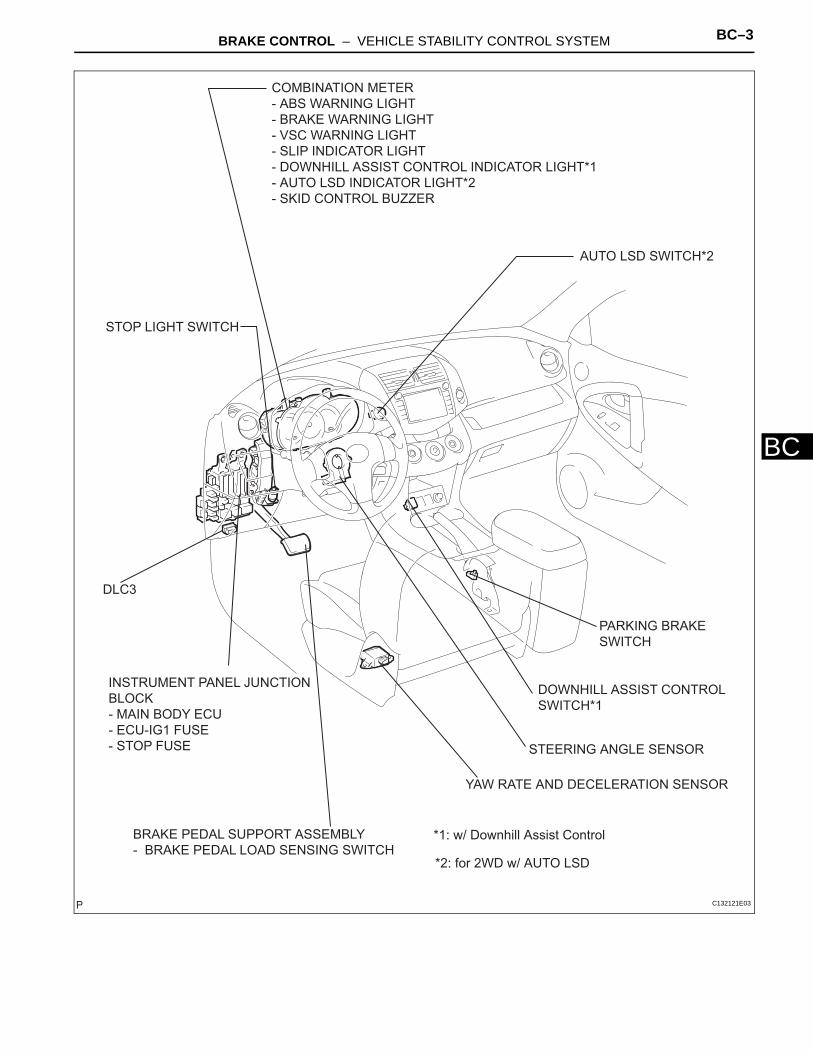
SYSTEM DIAGRAM
Skid Control ECU
Each Speed Sensor
Stop Light Switch
Engine Room No. 1 Junction Block
VSC FAIL Relay (Fail-safe Relay)
VSC MTR Relay (Motor Relay)
Pump Motor
Master Cylinder Pressure Sensor
Solenoid Relay
Solenoid (Control)
Solenoid (Linear)
1
2
ABS and TRACTION Actuator
: CAN Communication System
Downhill Assist Control Switch*1
BRK Relay(Stop Light Relay)
Stop Light
3
*1: w/ Downhill Assist Control
AUTO LSD Switch*2
*2: for 2WD w/ AUTO LSDC132092E03
BRAKE CONTROL – VEHICLE STABILITY CONTROL SYSTEM BC–5
BC
1
2
Steering Sensor
Yaw Rate and Deceleration Sensor
Main Body ECU
ECM
ABS Warning Light
VSC Warning Light
Brake Warning Light
Slip Indicator Light
Skid Control Buzzer
Speedometer
Combination Meter
: CAN Communication System
TS
Parking Brake Switch
Park / Neutral Position Switch
Crankshaft Position Sensor
Throttle Position Sensor
TCDLC3
Downhill Assist Control Indicator Light*1
3
*2: for 2WD w/ AUTO LSD
AUTO LSD Indicator Light*2
*1: w/ Downhill Assist Control
C136077E01
BC–6 BRAKE CONTROL – VEHICLE STABILITY CONTROL SYSTEM
BC
SYSTEM DESCRIPTION1. SYSTEM DESCRIPTION
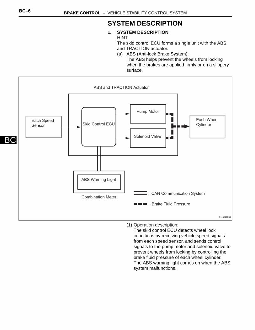
HINT:The skid control ECU forms a single unit with the ABS and TRACTION actuator.(a) ABS (Anti-lock Brake System):
The ABS helps prevent the wheels from locking when the brakes are applied firmly or on a slippery surface.
(1) Operation description: The skid control ECU detects wheel lock conditions by receiving vehicle speed signals from each speed sensor, and sends control signals to the pump motor and solenoid valve to prevent wheels from locking by controlling the brake fluid pressure of each wheel cylinder.The ABS warning light comes on when the ABS system malfunctions.
:
:
ABS and TRACTION Actuator
Skid Control ECUEach Speed
Sensor
Pump Motor
Solenoid Valve
Combination Meter
ABS Warning Light
CAN Communication System
Each Wheel
Cylinder
Brake Fluid Pressure
C115099E04
BRAKE CONTROL – VEHICLE STABILITY CONTROL SYSTEM BC–7
BC
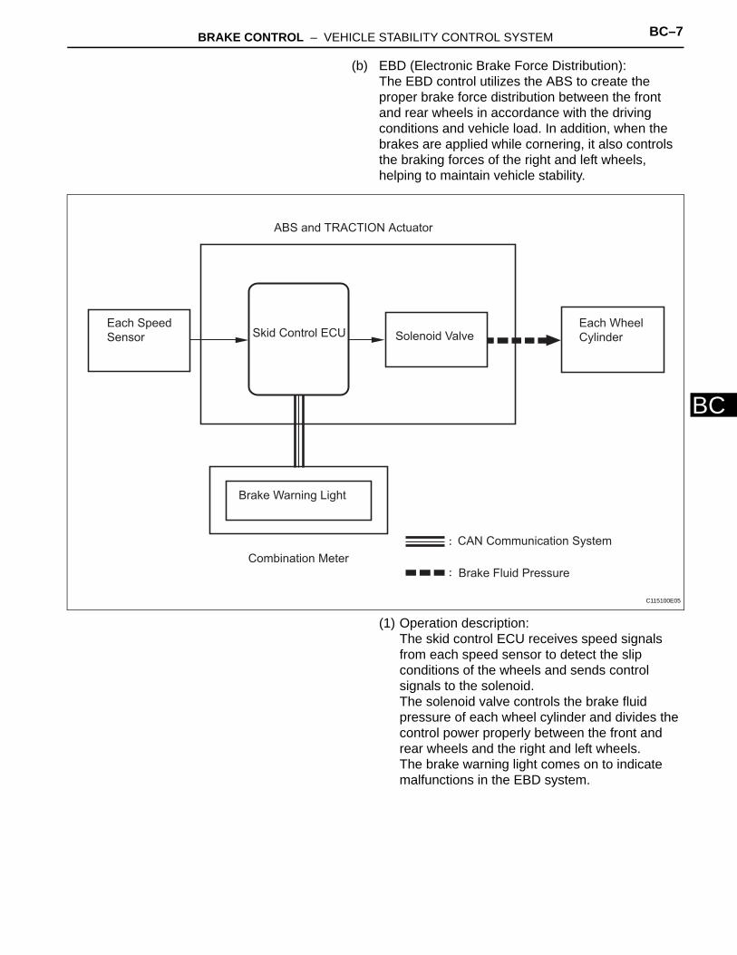
(b) EBD (Electronic Brake Force Distribution): The EBD control utilizes the ABS to create the proper brake force distribution between the front and rear wheels in accordance with the driving conditions and vehicle load. In addition, when the brakes are applied while cornering, it also controls the braking forces of the right and left wheels, helping to maintain vehicle stability.
(1) Operation description: The skid control ECU receives speed signals from each speed sensor to detect the slip conditions of the wheels and sends control signals to the solenoid.The solenoid valve controls the brake fluid pressure of each wheel cylinder and divides the control power properly between the front and rear wheels and the right and left wheels.The brake warning light comes on to indicate malfunctions in the EBD system.
:
:
ABS and TRACTION Actuator
Skid Control ECU Solenoid ValveEach Speed
Sensor
Combination Meter
Brake Warning Light
Each Wheel
Cylinder
CAN Communication System
Brake Fluid Pressure
C115100E05
BC–8 BRAKE CONTROL – VEHICLE STABILITY CONTROL SYSTEM
BC
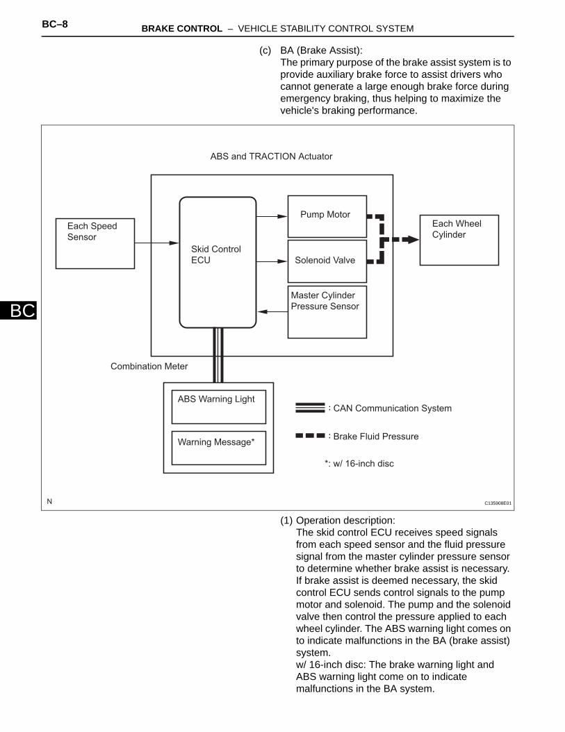
(c) BA (Brake Assist): The primary purpose of the brake assist system is to provide auxiliary brake force to assist drivers who cannot generate a large enough brake force during emergency braking, thus helping to maximize the vehicle's braking performance.
(1) Operation description: The skid control ECU receives speed signals from each speed sensor and the fluid pressure signal from the master cylinder pressure sensor to determine whether brake assist is necessary. If brake assist is deemed necessary, the skid control ECU sends control signals to the pump motor and solenoid. The pump and the solenoid valve then control the pressure applied to each wheel cylinder. The ABS warning light comes on to indicate malfunctions in the BA (brake assist) system. w/ 16-inch disc: The brake warning light and ABS warning light come on to indicate malfunctions in the BA system.
:
:
Each Speed
Sensor
Skid Control
ECU
Combination Meter
ABS and TRACTION Actuator
Pump Motor
Solenoid Valve
Master Cylinder
Pressure Sensor
Each Wheel
Cylinder
ABS Warning LightCAN Communication System
Brake Fluid PressureWarning Message*
*: w/ 16-inch disc
C135908E01
BRAKE CONTROL – VEHICLE STABILITY CONTROL SYSTEM BC–9
BC
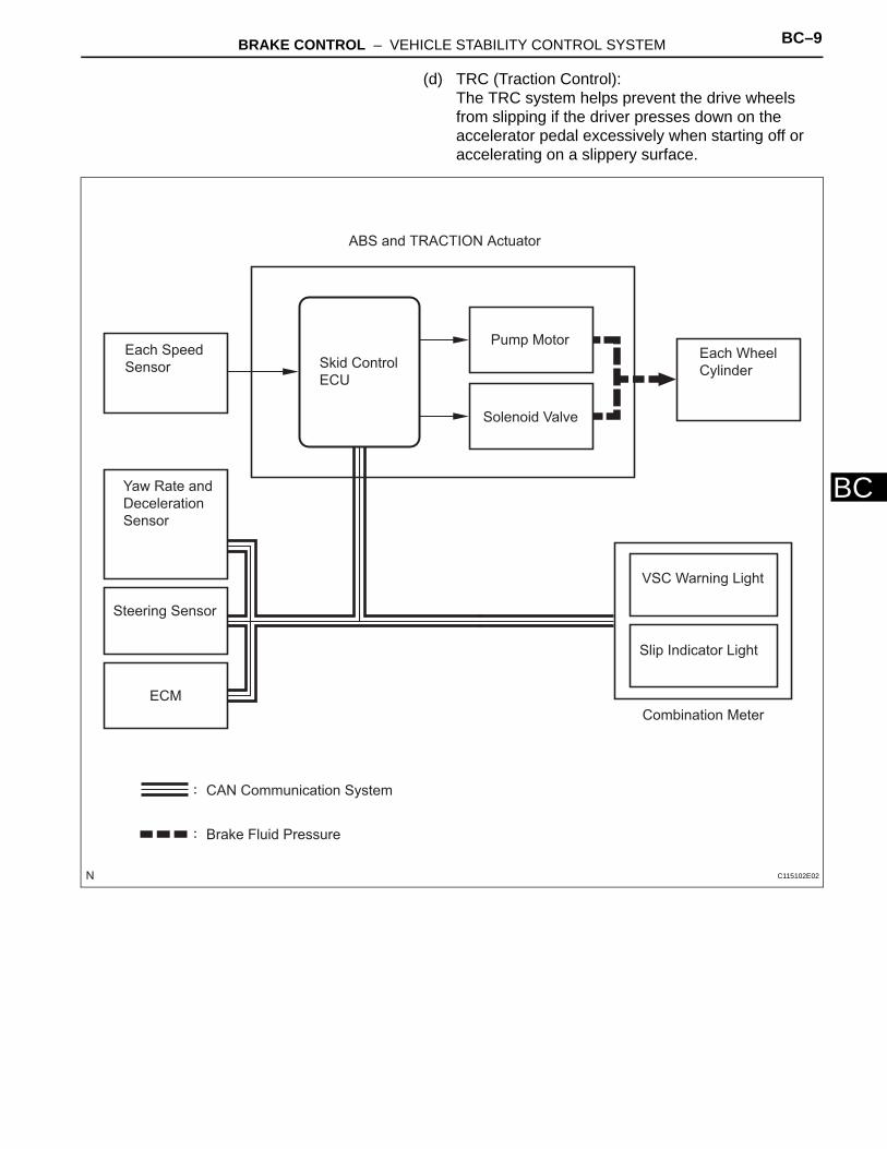
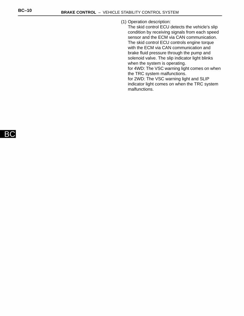
(d) TRC (Traction Control): The TRC system helps prevent the drive wheels from slipping if the driver presses down on the accelerator pedal excessively when starting off or accelerating on a slippery surface.
:
:
Each Speed
Sensor Skid Control
ECU
ABS and TRACTION Actuator
Yaw Rate and
Deceleration
Sensor
Steering Sensor
ECM
Combination Meter
VSC Warning Light
Slip Indicator Light
Each Wheel
Cylinder
Pump Motor
Solenoid Valve
CAN Communication System
Brake Fluid Pressure
C115102E02
BC–10 BRAKE CONTROL – VEHICLE STABILITY CONTROL SYSTEM
BC
(1) Operation description: The skid control ECU detects the vehicle's slip condition by receiving signals from each speed sensor and the ECM via CAN communication. The skid control ECU controls engine torque with the ECM via CAN communication and brake fluid pressure through the pump and solenoid valve. The slip indicator light blinks when the system is operating. for 4WD: The VSC warning light comes on when the TRC system malfunctions. for 2WD: The VSC warning light and SLIP indicator light comes on when the TRC system malfunctions.

BRAKE CONTROL – VEHICLE STABILITY CONTROL SYSTEM BC–11
BC
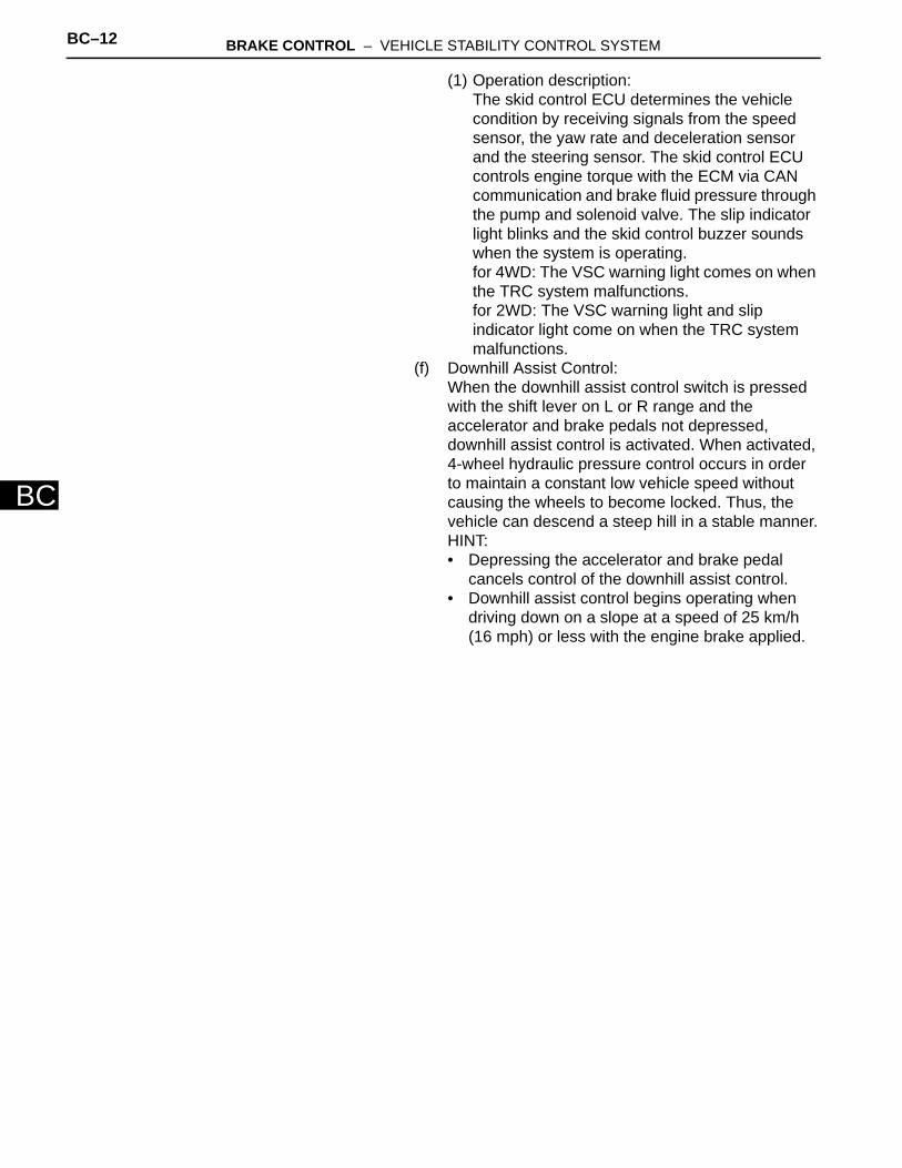
(e) VSC (Vehicle Stability Control): The VSC system helps prevent the vehicle from slipping sideways when front or rear wheel skidding occurs while cornering.
:
:
ABS and TRACTION Actuator
Combination Meter
VSC Warning Light
Slip Indicator Light
Skid Control Buzzer
Each Wheel
Cylinder
Each Speed
Sensor
Yaw Rate and
Deceleration
Sensor
Steering Sensor
ECM
CAN Communication System
Brake Fluid Pressure
Skid Control
ECU
Pump Motor
Solenoid Valve
C115103E02
BC–12 BRAKE CONTROL – VEHICLE STABILITY CONTROL SYSTEM
BC
(1) Operation description: The skid control ECU determines the vehicle condition by receiving signals from the speed sensor, the yaw rate and deceleration sensor and the steering sensor. The skid control ECU controls engine torque with the ECM via CAN communication and brake fluid pressure through the pump and solenoid valve. The slip indicator light blinks and the skid control buzzer sounds when the system is operating.for 4WD: The VSC warning light comes on when the TRC system malfunctions. for 2WD: The VSC warning light and slip indicator light come on when the TRC system malfunctions.
(f) Downhill Assist Control: When the downhill assist control switch is pressed with the shift lever on L or R range and the accelerator and brake pedals not depressed, downhill assist control is activated. When activated, 4-wheel hydraulic pressure control occurs in order to maintain a constant low vehicle speed without causing the wheels to become locked. Thus, the vehicle can descend a steep hill in a stable manner.HINT:• Depressing the accelerator and brake pedal
cancels control of the downhill assist control.• Downhill assist control begins operating when
driving down on a slope at a speed of 25 km/h (16 mph) or less with the engine brake applied.
BRAKE CONTROL – VEHICLE STABILITY CONTROL SYSTEM BC–13
BC
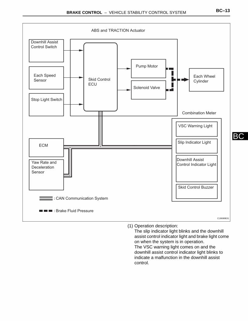
(1) Operation description: The slip indicator light blinks and the downhill assist control indicator light and brake light come on when the system is in operation.The VSC warning light comes on and the downhill assist control indicator light blinks to indicate a malfunction in the downhill assist control.
:
:
ABS and TRACTION Actuator
Combination Meter
VSC Warning Light
Slip Indicator Light
Downhill Assist
Control Indicator Light
Each Wheel
Cylinder
Each Speed
Sensor
Yaw Rate and
Deceleration
Sensor
ECM
CAN Communication System
Brake Fluid Pressure
Skid Control
ECU
Pump Motor
Solenoid Valve
Downhill Assist
Control Switch
Stop Light Switch
Skid Control Buzzer
C136089E01

BC–14 BRAKE CONTROL – VEHICLE STABILITY CONTROL SYSTEM
BC
(g) Hill-start assist control: When the vehicle starts off on a steep hill, hill-start assist control effects 4-wheel hydraulic pressure control to prevent the vehicle from rolling backwards.After a maximum of 2 seconds after the control has started, fluid pressure is gradually released and control will be complete.HINT:• Depressing the brake pedal cancels control of
the hill-start assist control.• Hill-start assist control does not operate when
the shift lever is in the P position, or when the vehicle is running, the parking brake lever is set, or the accelerator pedal is depressed.
:
:
ABS and TRACTION Actuator
Combination Meter
VSC Warning Light
Slip Indicator Light
Each Wheel
Cylinder
Each Speed
Sensor
ECM
CAN Communication System
Brake Fluid Pressure
Skid Control
ECU
Pump Motor
Solenoid Valve
Skid Control Buzzer
C132095E01
BRAKE CONTROL – VEHICLE STABILITY CONTROL SYSTEM BC–15
BC
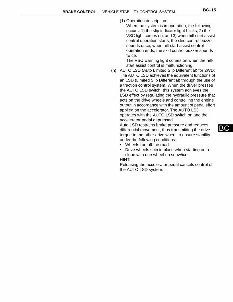
(1) Operation description: When the system is in operation, the following occurs: 1) the slip indicator light blinks; 2) the VSC light comes on; and 3) when hill-start assist control operation starts, the skid control buzzer sounds once; when hill-start assist control operation ends, the skid control buzzer sounds twice.The VSC warning light comes on when the hill-start assist control is malfunctioning.
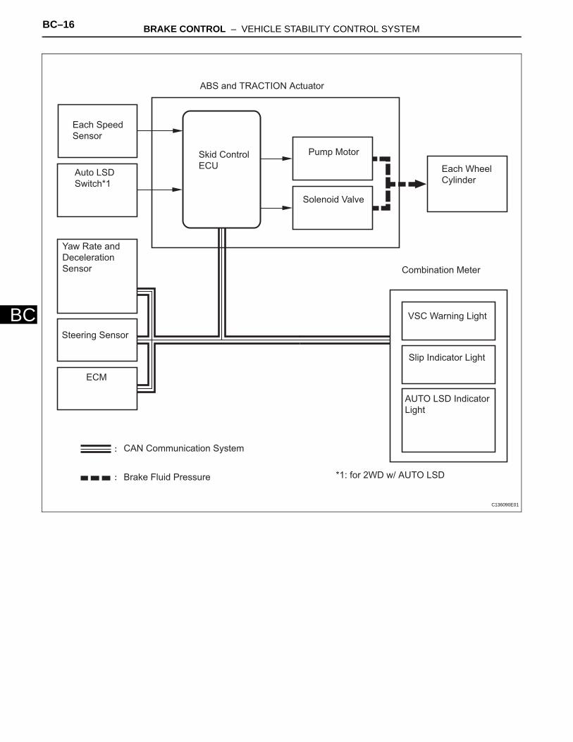
(h) AUTO LSD (Auto Limited Slip Differential) for 2WD: The AUTO LSD achieves the equivalent functions of an LSD (Limited Slip Differential) through the use of a traction control system. When the driver presses the AUTO LSD switch, this system achieves the LSD effect by regulating the hydraulic pressure that acts on the drive wheels and controlling the engine output in accordance with the amount of pedal effort applied on the accelerator. The AUTO LSD operates with the AUTO LSD switch on and the accelerator pedal depressed.Auto LSD restrains brake pressure and reduces differential movement, thus transmitting the drive torque to the other drive wheel to ensure stability under the following conditions:• Wheels run off the road.• Drive wheels spin in place when starting on a
slope with one wheel on snow/ice.HINT:Releasing the accelerator pedal cancels control of the AUTO LSD system.
BC–16 BRAKE CONTROL – VEHICLE STABILITY CONTROL SYSTEM
BC
:
:
ABS and TRACTION Actuator
Combination Meter
VSC Warning Light
Slip Indicator Light
Each Wheel
Cylinder
Each Speed
Sensor
ECM
CAN Communication System
Brake Fluid Pressure
Skid Control
ECU
Pump Motor
Solenoid Valve
Yaw Rate and
Deceleration
Sensor
Steering Sensor
Auto LSD
Switch*1
AUTO LSD Indicator
Light
*1: for 2WD w/ AUTO LSD
C136090E01
BRAKE CONTROL – VEHICLE STABILITY CONTROL SYSTEM BC–17
BC
(1) Operation description: The skid control ECU determines that the vehicle is in a state in which the AUTO LSD can operate by using various sensors and switches to detect the operating conditions of the AUTO LSD switch, shift position, accelerator pedal, and brake pedal. When the vehicle is in a state in which the AUTO LSD can operate, the skid control ECU effects hydraulic pressure control of the wheel cylinder at the wheel with the faster wheel speed so that the wheel speeds of the right and left drive wheels will become equal.The slip indicator light blinks and the AUTO LSD indicator light comes on when the system is operating. Both the VSC warning light and SLIP indicator light come on when the AUTO LSD system malfunctions.
2. COOPERATIVE CONTROL FUNCTION(a) Description
(1) Braking when Surface Resistance Differs Between Left and Right WheelsIf the driver suddenly applies the brakes on a road surface with a considerable difference in friction coefficient between the right and left wheels, the difference in the brake force between the right and left wheels will cause the vehicle posture to become unstable and create a yaw movement. In this state, the skid control ECU controls the VSC to stabilize the vehicle posture. At the same time, it effects cooperative control with the EPS to provide steering torque assist, which facilitates the driver's steering maneuvers to stabilize the vehicle posture.
(2) Accelerating when Surface Resistance Differs Between Left and Right WheelsIf the driver suddenly starts off or accelerates on a road surface with a considerable difference in friction coefficient between the right and left wheels, the slippage of a drive wheel will cause the vehicle posture to become unstable and negatively affect its acceleration performance. In this state, the skid control ECU causes the TRC to control the hydraulic brake of the slipping drive wheel, and requests the engine ECU to effect engine output control. At the same time, it effects cooperative control with the EPS to provide steering torque assist, which facilitates the driver's steering maneuvers to stabilize the vehicle posture.

BC–18 BRAKE CONTROL – VEHICLE STABILITY CONTROL SYSTEM
BC
(3) Front Wheel Skid TendencyWhen the skid control ECU determines that there is a front wheel skid tendency, it controls the VSC to dampen the front wheel skid. At the same time, it effects cooperative control with the EPS to provide steering torque assist, which facilitates the driver's steering maneuvers to stabilize the vehicle posture. To prevent excessive steering maneuvers, it provides a steering torque assist. This assist increases the resistance to counter the driver's steering effort, if the driver turns the steering wheel excessively.
(4) Rear Wheel Skid TendencyWhen the skid control ECU determines that there is a rear wheel skid tendency, it controls the VSC to dampen the rear wheel skid. At the same time, it effects cooperative control with the EPS to provide steering torque assist, which facilitates the driver's steering maneuvers in the direction to correct the rear wheel skid.
(5) Acceleration During CorneringA sudden acceleration of the vehicle during cornering may cause a drive wheel to freewheel, which could cause the front wheels or rear wheels to skid. If the skid control ECU determines that there is freewheeling of a drive wheel, a front wheel skid tendency, or a rear wheel skid tendency, it effects cooperative control with the 4WD system to optimally control the drive torque distribution to the front and rear wheels. Furthermore, it controls the TRC and the VSC as needed to ensure driving stability and acceleration performance.
(b) OperationThe operation of the solenoid valves under the cooperative control is the same as the TRC or VSC operation.
3. ABS WITH EBD, BA, TRC AND VSC OPERATION (a) The skid control ECU calculates vehicle stability
tendency based on the signals from the 4 wheel speed sensors, the yaw rate and deceleration sensor and the steering sensor. In addition, it evaluates the results of the calculations to determine whether any control actions (control of the engine output torque by electronic throttle control and of the brake fluid pressure by the ABS and TRACTION actuator) should be implemented.
(b) The slip indicator blinks and the skid control buzzer sounds to inform the driver that the VSC system is operating. The slip indicator also blinks when traction control is operating, and the operation being performed is displayed.
BRAKE CONTROL – VEHICLE STABILITY CONTROL SYSTEM BC–19
BC
4. FAIL SAFE FUNCTION(a) When a failure occurs in the ABS with BA, TRC and
VSC systems, the ABS and VSC warning lights illuminate, the slip indicator light comes on*1 or remains off*2, and the operations of those systems are prohibited. In addition to this, when a failure which disables the EBD operation occurs, the brake warning light comes on and its operation is prohibited.HINT:*1: for 2WD*2: for 4WD
(b) If control is prohibited due to a malfunction during operation, control is disabled gradually to avoid sudden vehicle instability.
5. INITIAL CHECK(a) When the vehicle speed first reaches approximately
6 km/h (4 mph) or more after the ignition switch is turned ON, each solenoid valve and the motor of the ABS and TRACTION actuator are sequentially activated to perform electrical checks. During the initial check, the operating sound of the solenoid valve and motor can be heard from the engine compartment, but this does not indicate a malfunction.
6. SERVICE MODE(a) VSC operation can be disabled by operating the
intelligent tester.HINT:Refer to the intelligent tester operator's manual for further details.
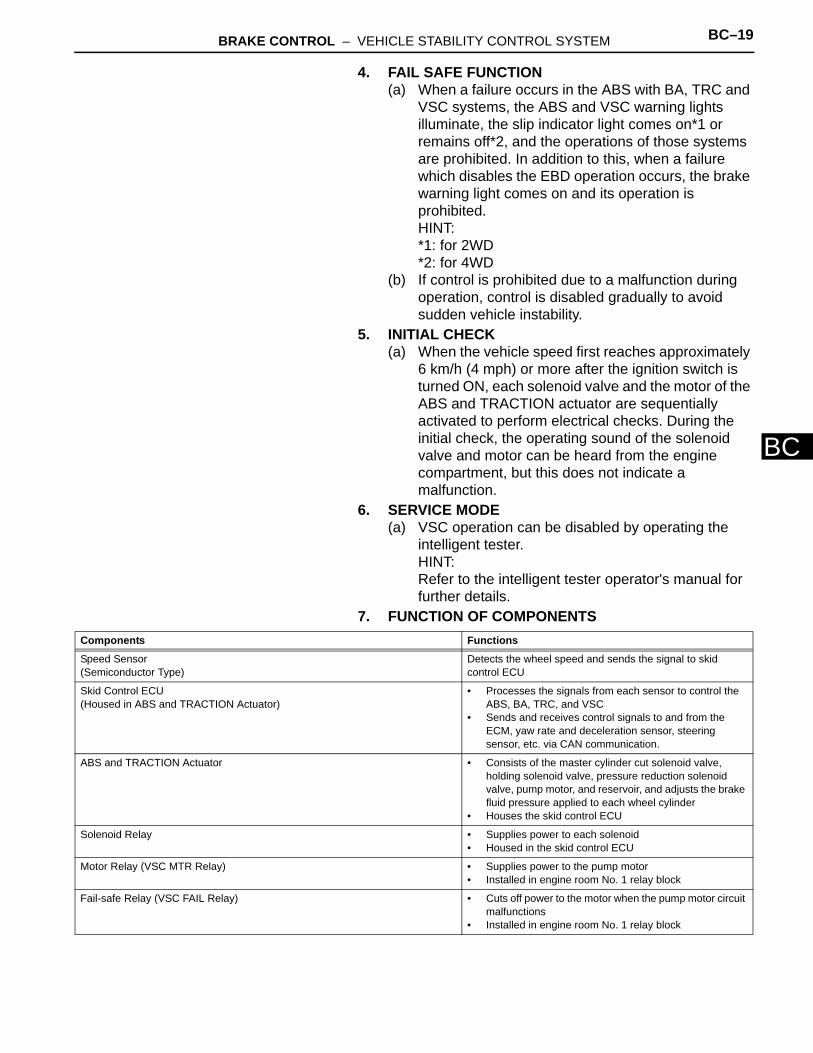
7. FUNCTION OF COMPONENTSComponents Functions
Speed Sensor(Semiconductor Type)
Detects the wheel speed and sends the signal to skid control ECU
Skid Control ECU(Housed in ABS and TRACTION Actuator)
• Processes the signals from each sensor to control the ABS, BA, TRC, and VSC
• Sends and receives control signals to and from the ECM, yaw rate and deceleration sensor, steering sensor, etc. via CAN communication.
ABS and TRACTION Actuator • Consists of the master cylinder cut solenoid valve, holding solenoid valve, pressure reduction solenoid valve, pump motor, and reservoir, and adjusts the brake fluid pressure applied to each wheel cylinder
• Houses the skid control ECU
Solenoid Relay • Supplies power to each solenoid• Housed in the skid control ECU
Motor Relay (VSC MTR Relay) • Supplies power to the pump motor• Installed in engine room No. 1 relay block
Fail-safe Relay (VSC FAIL Relay) • Cuts off power to the motor when the pump motor circuit malfunctions
• Installed in engine room No. 1 relay block

BC–20 BRAKE CONTROL – VEHICLE STABILITY CONTROL SYSTEM
BC
HINT:*1: w/ Downhill assist control*2: for 2WD w/ AUTO LSD
Steering Sensor • Detects the steering extent and direction and sends signals to the skid control ECU via CAN communication
• Has a magnetic resistance element which detects the rotation of the magnet housed in the detection gear in order to detect the changes in magnetic resistance and the steering amount and direction
Yaw Rate and Deceleration Sensor • Yaw rate sensor detects the vehicle's angular velocity (yaw rate) in the vertical direction based on the extent and direction of the deflection of the piezoelectric ceramics
• Deceleration sensor measures the capacity of the condenser that changes the distance between the electrodes depending on G force, which occurs when the vehicle is accelerated, and converts the measured value into electrical signals
• Sends signals to the skid control ECU via CAN communication
Master Cylinder Pressure Sensor • Detects the brake fluid pressure in the master cylinder• Housed in the ABS and TRACTION actuator
ECM • Controls the engine output when TRC and VSC are operating with the skid control ECU via CAN communication
Downhill Assist Control switch*1 Allows the driver to turn downhill assist control ON and OFF
AUTO LSD switch*2 Allows the driver to turn AUTO LSD ON and OFF
Combination Meter ABS Warning Light • Illuminates to inform the driver that a malfunction in the ABS has occurred
• Blinks to indicate DTCs that relate to the ABS
VSC Warning Light • Illuminates to inform the driver that a malfunction in the VSC system has occurred
• Blinks to indicate DTCs that relate to the VSC
Brake Warning light • Illuminates to inform the driver that the parking brake is ON when the system is normal, and when the brake fluid has decreased
• Illuminates to inform the driver that a malfunction in the EBD has occurred
Slip Indicator Light • Blinks to inform the driver that TRC, VSC, downhill assist control and hill-start assist control are operating
• Illuminates to inform the driver that a malfunction has occurred in the TRC or VSC system
AUTO LSD Indicator Light*2 Lights up to inform the driver when AUTO LSD operation is possible
Downhill Assist Control Indicator Light*1
Lights up to inform the driver when downhill assist control operation is possible
Skid Control Buzzer • Intermittently sounds to inform the driver that the VSC is operating
• Housed in the combination meter
Components Functions
BRAKE CONTROL – VEHICLE STABILITY CONTROL SYSTEM BC–21
BC
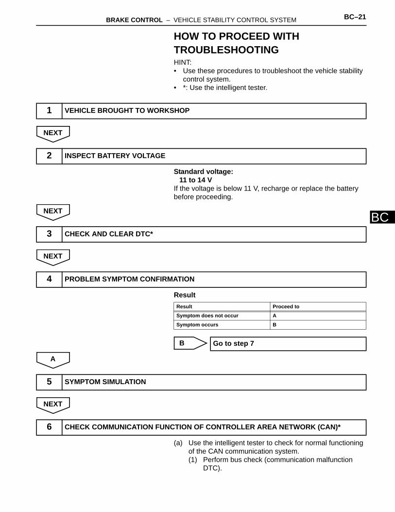
HOW TO PROCEED WITH TROUBLESHOOTINGHINT:• Use these procedures to troubleshoot the vehicle stability
control system.• *: Use the intelligent tester.
NEXT
Standard voltage:11 to 14 V
If the voltage is below 11 V, recharge or replace the battery before proceeding.
NEXT
NEXT
Result
B
A
NEXT
(a) Use the intelligent tester to check for normal functioning of the CAN communication system.(1) Perform bus check (communication malfunction
DTC).
1 VEHICLE BROUGHT TO WORKSHOP
2 INSPECT BATTERY VOLTAGE
3 CHECK AND CLEAR DTC*
4 PROBLEM SYMPTOM CONFIRMATION
Result Proceed to
Symptom does not occur A
Symptom occurs B
Go to step 7
5 SYMPTOM SIMULATION
6 CHECK COMMUNICATION FUNCTION OF CONTROLLER AREA NETWORK (CAN)*
BC–22 BRAKE CONTROL – VEHICLE STABILITY CONTROL SYSTEM
BC
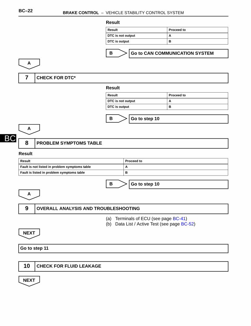
Result
B
A
Result
B
A
Result
B
A
(a) Terminals of ECU (see page BC-41)(b) Data List / Active Test (see page BC-52)
NEXT
NEXT
Result Proceed to
DTC is not output A
DTC is output B
Go to CAN COMMUNICATION SYSTEM
7 CHECK FOR DTC*
Result Proceed to
DTC is not output A
DTC is output B
Go to step 10
8 PROBLEM SYMPTOMS TABLE
Result Proceed to
Fault is not listed in problem symptoms table A
Fault is listed in problem symptoms table B
Go to step 10
9 OVERALL ANALYSIS AND TROUBLESHOOTING
Go to step 11
10 CHECK FOR FLUID LEAKAGE

BRAKE CONTROL – VEHICLE STABILITY CONTROL SYSTEM BC–23
BC
NEXT
NEXT
11 REPAIR OR REPLACE
12 CONFIRMATION TEST
END
BC–24 BRAKE CONTROL – VEHICLE STABILITY CONTROL SYSTEM
BC
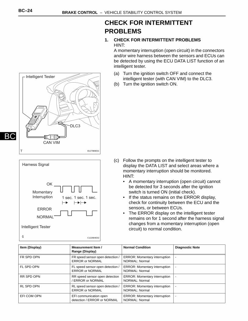
CHECK FOR INTERMITTENT PROBLEMS1. CHECK FOR INTERMITTENT PROBLEMS
HINT:A momentary interruption (open circuit) in the connectors and/or wire harness between the sensors and ECUs can be detected by using the ECU DATA LIST function of an intelligent tester.(a) Turn the ignition switch OFF and connect the
intelligent tester (with CAN VIM) to the DLC3.(b) Turn the ignition switch ON.
(c) Follow the prompts on the intelligent tester to display the DATA LIST and select areas where a momentary interruption should be monitored.HINT:• A momentary interruption (open circuit) cannot
be detected for 3 seconds after the ignition switch is turned ON (initial check).
• If the status remains on the ERROR display, check for continuity between the ECU and the sensors, or between ECUs.
• The ERROR display on the intelligent tester remains on for 1 second after the harness signal changes from a momentary interruption (open circuit) to normal condition.
Intelligent Tester
CAN VIM
DLC3
B127989E01
Harness Signal
OK
MomentaryInterruption 1 sec. 1 sec. 1 sec.
ERROR
NORMAL
Intelligent Tester
C122684E02
Item (Display) Measurement Item /Range (Display)
Normal Condition Diagnostic Note
FR SPD OPN FR speed sensor open detection / ERROR or NORMAL
ERROR: Momentary interruptionNORMAL: Normal
-
FL SPD OPN FL speed sensor open detection / ERROR or NORMAL
ERROR: Momentary interruptionNORMAL: Normal
-
RR SPD OPN RR speed sensor open detection / ERROR or NORMAL
ERROR: Momentary interruptionNORMAL: Normal
-
RL SPD OPN RL speed sensor open detection / ERROR or NORMAL
ERROR: Momentary interruptionNORMAL: Normal
-
EFI COM OPN EFI communication open detection / ERROR or NORMAL
ERROR: Momentary interruptionNORMAL: Normal
-
BRAKE CONTROL – VEHICLE STABILITY CONTROL SYSTEM BC–25
BC
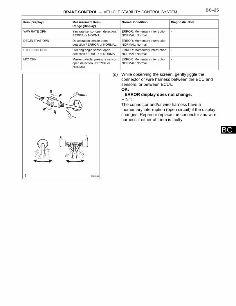
(d) While observing the screen, gently jiggle the connector or wire harness between the ECU and sensors, or between ECUs.OK:
ERROR display does not change.HINT:The connector and/or wire harness have a momentary interruption (open circuit) if the display changes. Repair or replace the connector and wire harness if either of them is faulty.
YAW RATE OPN Yaw rate sensor open detection / ERROR or NORMAL
ERROR: Momentary interruptionNORMAL: Normal
-
DECELERAT OPN Deceleration sensor open detection / ERROR or NORMAL
ERROR: Momentary interruptionNORMAL: Normal
-
STEERING OPN Steering angle sensor open detection / ERROR or NORMAL
ERROR: Momentary interruptionNORMAL: Normal
-
M/C OPN Master cylinder pressure sensor open detection / ERROR or NORMAL
ERROR: Momentary interruptionNORMAL: Normal
-
Item (Display) Measurement Item /Range (Display)
Normal Condition Diagnostic Note
C122685
BC–26 BRAKE CONTROL – VEHICLE STABILITY CONTROL SYSTEM
BC
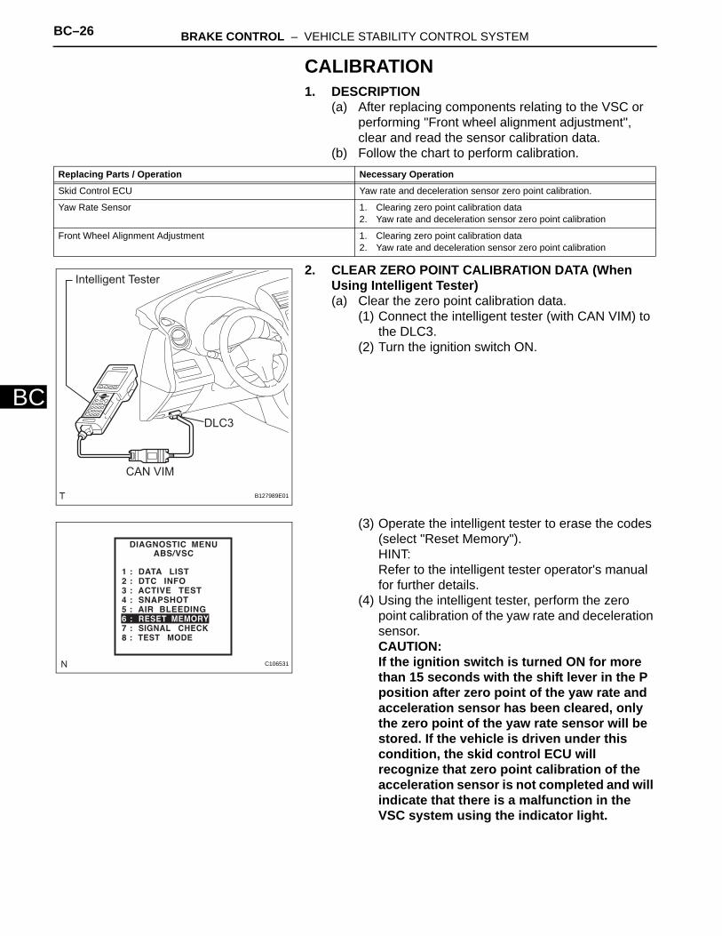
CALIBRATION1. DESCRIPTION
(a) After replacing components relating to the VSC or performing "Front wheel alignment adjustment", clear and read the sensor calibration data.
(b) Follow the chart to perform calibration.
2. CLEAR ZERO POINT CALIBRATION DATA (When Using Intelligent Tester)(a) Clear the zero point calibration data.
(1) Connect the intelligent tester (with CAN VIM) to the DLC3.
(2) Turn the ignition switch ON.
(3) Operate the intelligent tester to erase the codes (select "Reset Memory"). HINT:Refer to the intelligent tester operator's manual for further details.
(4) Using the intelligent tester, perform the zero point calibration of the yaw rate and deceleration sensor. CAUTION:If the ignition switch is turned ON for more than 15 seconds with the shift lever in the P position after zero point of the yaw rate and acceleration sensor has been cleared, only the zero point of the yaw rate sensor will be stored. If the vehicle is driven under this condition, the skid control ECU will recognize that zero point calibration of the acceleration sensor is not completed and will indicate that there is a malfunction in the VSC system using the indicator light.
Replacing Parts / Operation Necessary Operation
Skid Control ECU Yaw rate and deceleration sensor zero point calibration.
Yaw Rate Sensor 1. Clearing zero point calibration data2. Yaw rate and deceleration sensor zero point calibration
Front Wheel Alignment Adjustment 1. Clearing zero point calibration data2. Yaw rate and deceleration sensor zero point calibration
Intelligent Tester
CAN VIM
DLC3
B127989E01
C106531
BRAKE CONTROL – VEHICLE STABILITY CONTROL SYSTEM BC–27
BC
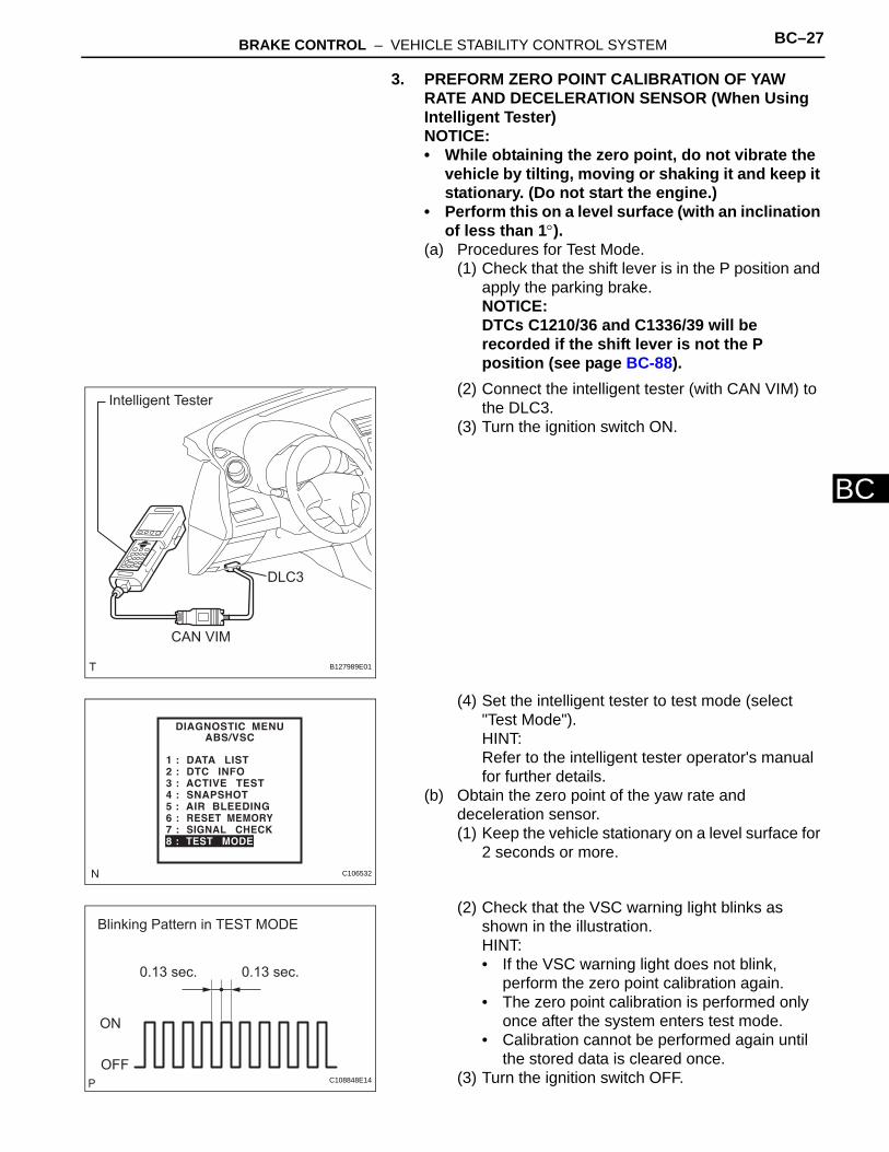
3. PREFORM ZERO POINT CALIBRATION OF YAW RATE AND DECELERATION SENSOR (When Using Intelligent Tester)NOTICE:• While obtaining the zero point, do not vibrate the
vehicle by tilting, moving or shaking it and keep it stationary. (Do not start the engine.)
• Perform this on a level surface (with an inclination of less than 1°).
(a) Procedures for Test Mode.(1) Check that the shift lever is in the P position and
apply the parking brake.NOTICE:DTCs C1210/36 and C1336/39 will be recorded if the shift lever is not the P position (see page BC-88).
(2) Connect the intelligent tester (with CAN VIM) to the DLC3.
(3) Turn the ignition switch ON.
(4) Set the intelligent tester to test mode (select "Test Mode").HINT:Refer to the intelligent tester operator's manual for further details.
(b) Obtain the zero point of the yaw rate and deceleration sensor.(1) Keep the vehicle stationary on a level surface for
2 seconds or more.
(2) Check that the VSC warning light blinks as shown in the illustration.HINT:• If the VSC warning light does not blink,
perform the zero point calibration again.• The zero point calibration is performed only
once after the system enters test mode.• Calibration cannot be performed again until
the stored data is cleared once. (3) Turn the ignition switch OFF.
Intelligent Tester
CAN VIM
DLC3
B127989E01
C106532
0.13 sec. 0.13 sec.
ON
OFF
Blinking Pattern in TEST MODE
C108848E14
BC–28 BRAKE CONTROL – VEHICLE STABILITY CONTROL SYSTEM
BC
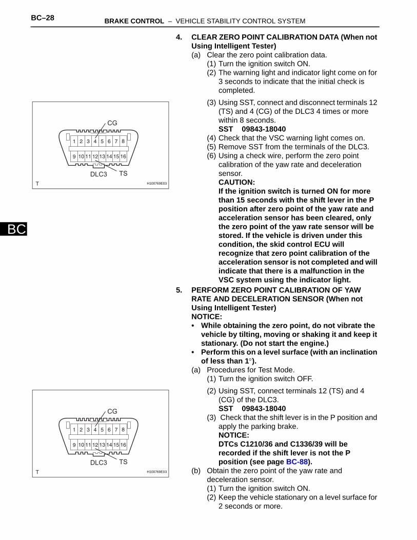
4. CLEAR ZERO POINT CALIBRATION DATA (When not Using Intelligent Tester)(a) Clear the zero point calibration data.
(1) Turn the ignition switch ON.(2) The warning light and indicator light come on for
3 seconds to indicate that the initial check is completed.
(3) Using SST, connect and disconnect terminals 12 (TS) and 4 (CG) of the DLC3 4 times or more within 8 seconds.SST 09843-18040
(4) Check that the VSC warning light comes on.(5) Remove SST from the terminals of the DLC3.(6) Using a check wire, perform the zero point
calibration of the yaw rate and deceleration sensor.CAUTION:If the ignition switch is turned ON for more than 15 seconds with the shift lever in the P position after zero point of the yaw rate and acceleration sensor has been cleared, only the zero point of the yaw rate sensor will be stored. If the vehicle is driven under this condition, the skid control ECU will recognize that zero point calibration of the acceleration sensor is not completed and will indicate that there is a malfunction in the VSC system using the indicator light.
5. PERFORM ZERO POINT CALIBRATION OF YAW RATE AND DECELERATION SENSOR (When not Using Intelligent Tester)NOTICE:• While obtaining the zero point, do not vibrate the
vehicle by tilting, moving or shaking it and keep it stationary. (Do not start the engine.)
• Perform this on a level surface (with an inclination of less than 1°).
(a) Procedures for Test Mode.(1) Turn the ignition switch OFF.(2) Using SST, connect terminals 12 (TS) and 4
(CG) of the DLC3.SST 09843-18040
(3) Check that the shift lever is in the P position and apply the parking brake.NOTICE:DTCs C1210/36 and C1336/39 will be recorded if the shift lever is not the P position (see page BC-88).
(b) Obtain the zero point of the yaw rate and deceleration sensor.(1) Turn the ignition switch ON.(2) Keep the vehicle stationary on a level surface for
2 seconds or more.
CG
TSDLC3H100769E03
CG
TSDLC3H100769E03

BRAKE CONTROL – VEHICLE STABILITY CONTROL SYSTEM BC–29
BC
(3) Check that the VSC warning light blinks as shown in the illustration.HINT:• If the VSC warning light does not blink,
perform the zero point calibration again.• The zero point calibration is performed only
once after the system enters test mode.• Calibration cannot be performed again until
the stored data is cleared once. (4) Turn the ignition switch OFF.
0.13 sec. 0.13 sec.
ON
OFF
Blinking Pattern in TEST MODE
C108848E14
BC–30 BRAKE CONTROL – VEHICLE STABILITY CONTROL SYSTEM
BC
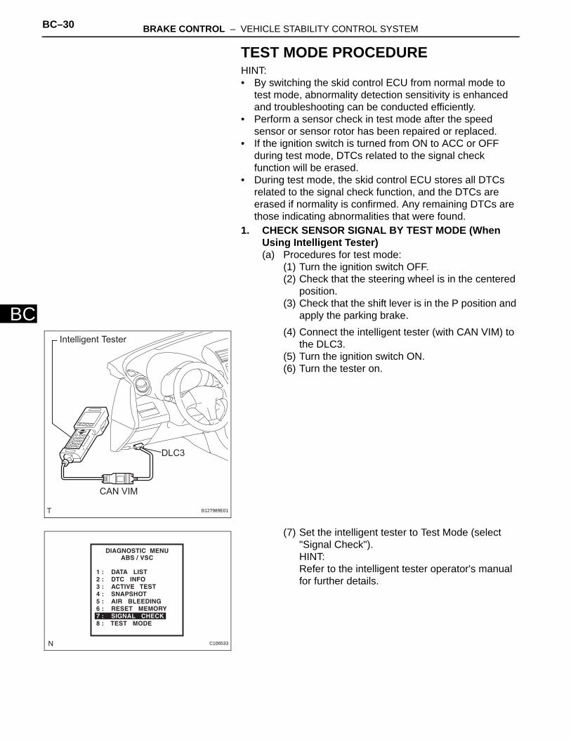
TEST MODE PROCEDUREHINT:• By switching the skid control ECU from normal mode to
test mode, abnormality detection sensitivity is enhanced and troubleshooting can be conducted efficiently.
• Perform a sensor check in test mode after the speed sensor or sensor rotor has been repaired or replaced.
• If the ignition switch is turned from ON to ACC or OFF during test mode, DTCs related to the signal check function will be erased.
• During test mode, the skid control ECU stores all DTCs related to the signal check function, and the DTCs are erased if normality is confirmed. Any remaining DTCs are those indicating abnormalities that were found.
1. CHECK SENSOR SIGNAL BY TEST MODE (When Using Intelligent Tester)(a) Procedures for test mode:
(1) Turn the ignition switch OFF.(2) Check that the steering wheel is in the centered
position.(3) Check that the shift lever is in the P position and
apply the parking brake.(4) Connect the intelligent tester (with CAN VIM) to
the DLC3.(5) Turn the ignition switch ON.(6) Turn the tester on.
(7) Set the intelligent tester to Test Mode (select "Signal Check").HINT:Refer to the intelligent tester operator's manual for further details.
Intelligent Tester
CAN VIM
DLC3
B127989E01
C106533

BRAKE CONTROL – VEHICLE STABILITY CONTROL SYSTEM BC–31
BC
(8) Check that the ABS warning light and VSC warning light blink as shown in the illustration.HINT:If the ABS warning light and VSC warning warning light do not blink, check the TS and CG terminal circuit, and ABS and VSC warning light circuits.
(9) Start the engine.(b) w/ 16-inch disc only:
Check the lost booster pressure judgment and perform the master cylinder pressure sensor zero point calibration.NOTICE:Preform the check in the lost booster pressure state (negative pressure in the booster is depressurized).(1) Turn the ignition switch ON.(2) Check that the brake warning light comes on
when depressing the brake pedal with a force of 59 N (6 kgf, 13.2 lbf) or more for 1 second or more. (The lost booster pressure state is judged normal.)
(3) Start the engine depressing the brake pedal with a force of 59 N (6 kgf, 13.2 lbf) or more for 1 second or more.
(4) Check that the brake warning light goes off when quickly releasing the brake pedal. (The lost booster pressure state is judged normal.)
(5) Leave the vehicle for 1 second or more. (Master cylinder pressure sensor zero point calibration.)NOTICE:• If you slowly depress the brake pedal or
depress it again, master cylinder pressure sensor zero point calibration is not performed normally.
• If the lost booster pressure judgment check is not completed normally, the master cylinder pressure sensor check is not judged.
• If a recheck is performed after the engine has started, end the Test Mode, enter Test Mode again, and release the vacuum in the booster by pumping the brake pedal prior to the recheck.
0.13 sec. 0.13 sec.
ON
OFF
Blinking Pattern in TEST MODE
C108848E14
Section Title See procedure
ABS Warning Light does not Come ON BC-138
VSC Warning Light does not Come ON BC-142
TS and CG Terminal Circuit BC-177

BC–32 BRAKE CONTROL – VEHICLE STABILITY CONTROL SYSTEM
BC
(c) Check the deceleration sensor.(1) Keep the vehicle stationary on a level surface for
1 second or more.HINT:The deceleration sensor check can be performed together with the following master cylinder pressure sensor check.
(d) Check the master cylinder pressure sensor.(1) Leave the vehicle in a stationary condition and
release the brake pedal for 1 second or more, and quickly depress the brake pedal with a force of 98 N (10 kgf, 22 lbf) or more for 1 second.Check that the ABS warning light remains illuminated for 3 seconds.HINT:• Ensure that the ABS warning light comes on.• While the ABS warning light remains
illuminated, continue depressing the brake pedal with a force of 98 N (10 kgf, 22 lbf) or more.
• The ABS warning light comes on for 3 seconds every time the brake pedal operation above is performed.
(e) Check the speed sensor.(1) Check that the ABS warning light is blinking as
shown in the illustration.(2) Check the speed sensor signal.
1. Drive the vehicle straight forward at a speed of 45 km/h (28 mph) or more for several seconds.
2. Check that the ABS warning light goes off.NOTICE:• The speed sensor check may not be
completed if the sensor check is started with the steering wheel turned or one or more wheels spinning.
• If the speed sensor check is commenced while the steering wheel is turned, the ABS warning light may come on after the low speed check is finished.
• The ABS warning light comes on immediately when an abnormality is detected.
• When the speed sensor signal is normal, the ABS warning light goes off while driving at 45 km/h (28 mph) or more, and blinks in the test mode pattern while the vehicle is stationary.
ABS Warning Light
0.13 sec. 0.13 sec.
ON
OFFC108848E01

BRAKE CONTROL – VEHICLE STABILITY CONTROL SYSTEM BC–33
BC
• Do not drive the vehicle at a speed of 80 km/h (50 mph) or more after the ABS warning light turns off, because test mode DTCs are set again when the vehicle speed exceeds 80 km/h (50 mph).
3. Stop the vehicle.(f) Check the yaw rate sensor.
(1) Move the shift lever to P and set the parking brake lever.
(2) Check that the VSC warning light is blinking as shown in the illustration.
(3) Keep the vehicle stationary on a level surface for 1 second or more.
Vehicle Speed: km/h (mph)
ABS Warning Light
Time
ON
OFF
45 (28)
5 (3)
0 (0)
Low Speed Check Middle Speed
Check
Blinking pattern in speed sensor check:
C115115E04
0.13 sec. 0.13 sec.
ON
OFF
Blinking Pattern in TEST MODE
C108848E14
BC–34 BRAKE CONTROL – VEHICLE STABILITY CONTROL SYSTEM
BC
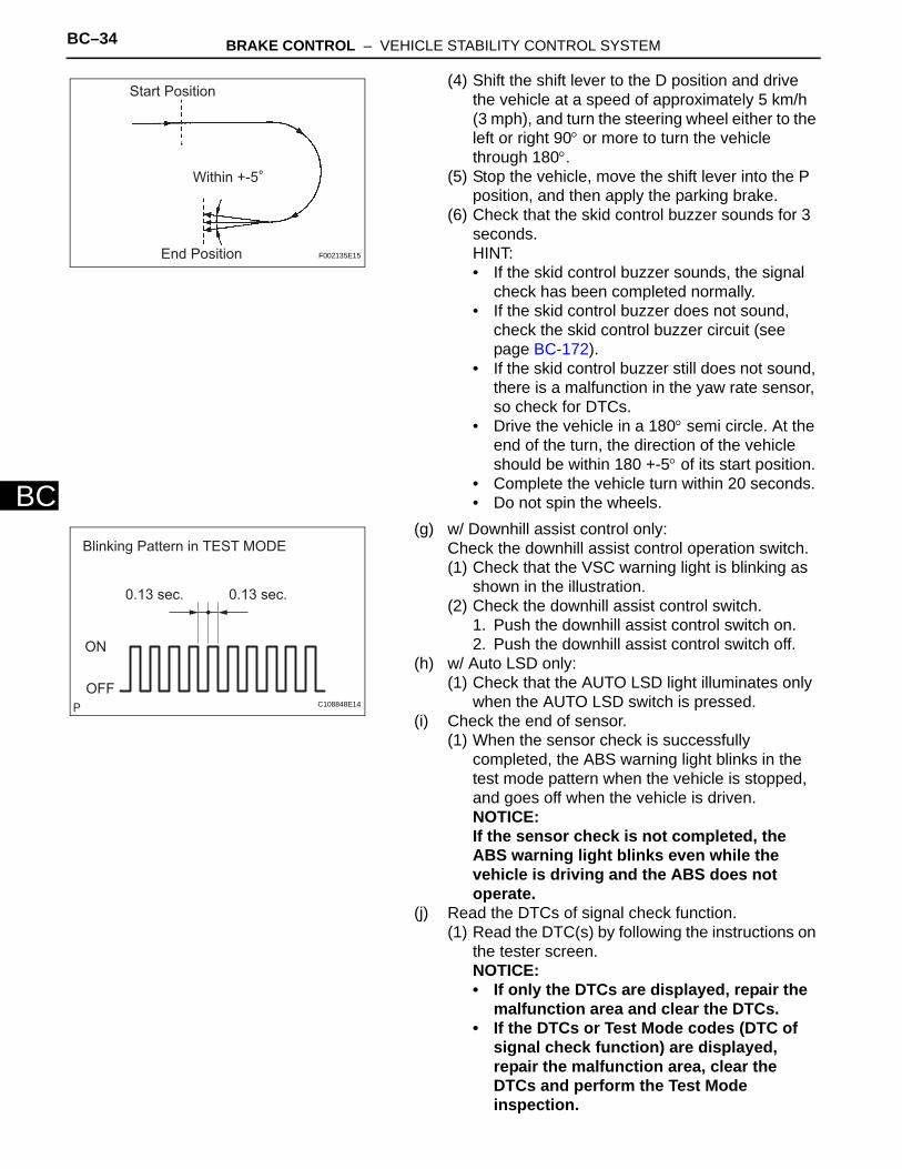
(4) Shift the shift lever to the D position and drive the vehicle at a speed of approximately 5 km/h (3 mph), and turn the steering wheel either to the left or right 90° or more to turn the vehicle through 180°.
(5) Stop the vehicle, move the shift lever into the P position, and then apply the parking brake.
(6) Check that the skid control buzzer sounds for 3 seconds.HINT:• If the skid control buzzer sounds, the signal
check has been completed normally.• If the skid control buzzer does not sound,
check the skid control buzzer circuit (see page BC-172).
• If the skid control buzzer still does not sound, there is a malfunction in the yaw rate sensor, so check for DTCs.
• Drive the vehicle in a 180° semi circle. At the end of the turn, the direction of the vehicle should be within 180 +-5° of its start position.
• Complete the vehicle turn within 20 seconds.• Do not spin the wheels.
(g) w/ Downhill assist control only:Check the downhill assist control operation switch.(1) Check that the VSC warning light is blinking as
shown in the illustration.(2) Check the downhill assist control switch.
1. Push the downhill assist control switch on.2. Push the downhill assist control switch off.
(h) w/ Auto LSD only:(1) Check that the AUTO LSD light illuminates only
when the AUTO LSD switch is pressed.(i) Check the end of sensor.
(1) When the sensor check is successfully completed, the ABS warning light blinks in the test mode pattern when the vehicle is stopped, and goes off when the vehicle is driven.NOTICE:If the sensor check is not completed, the ABS warning light blinks even while the vehicle is driving and the ABS does not operate.
(j) Read the DTCs of signal check function.(1) Read the DTC(s) by following the instructions on
the tester screen.NOTICE:• If only the DTCs are displayed, repair the
malfunction area and clear the DTCs.• If the DTCs or Test Mode codes (DTC of
signal check function) are displayed, repair the malfunction area, clear the DTCs and perform the Test Mode inspection.
Start Position
End Position
Within +-5
F002135E15
0.13 sec. 0.13 sec.
ON
OFF
Blinking Pattern in TEST MODE
C108848E14
BRAKE CONTROL – VEHICLE STABILITY CONTROL SYSTEM BC–35
BC
HINT:See the list of the DTCs (refer to "DTC OF TEST MODE FUNCTION (SIGNAL CHECK)" below).
2. CHECK SENSOR SIGNAL BY TEST MODE (When not Using Intelligent Tester)(a) Procedures for test mode:
(1) Turn the ignition switch OFF.(2) Check that the steering wheel is in the centered
position.(3) Check that the shift lever is in the P position and
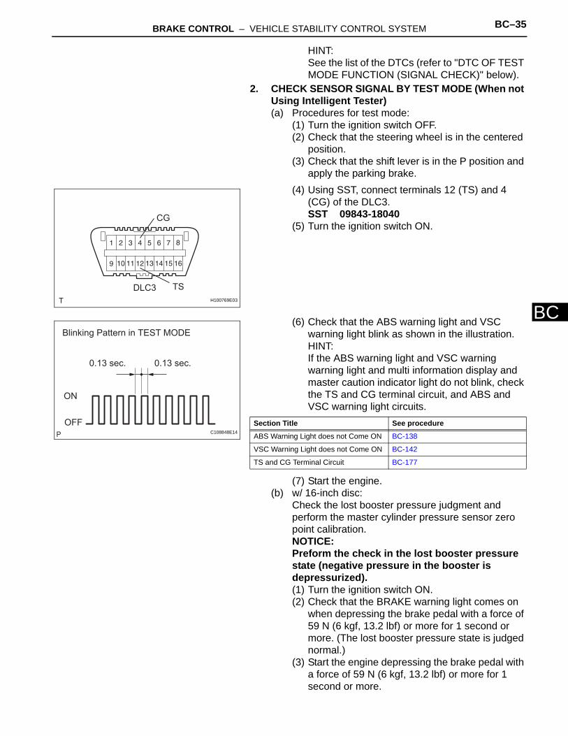
apply the parking brake.(4) Using SST, connect terminals 12 (TS) and 4
(CG) of the DLC3.SST 09843-18040
(5) Turn the ignition switch ON.
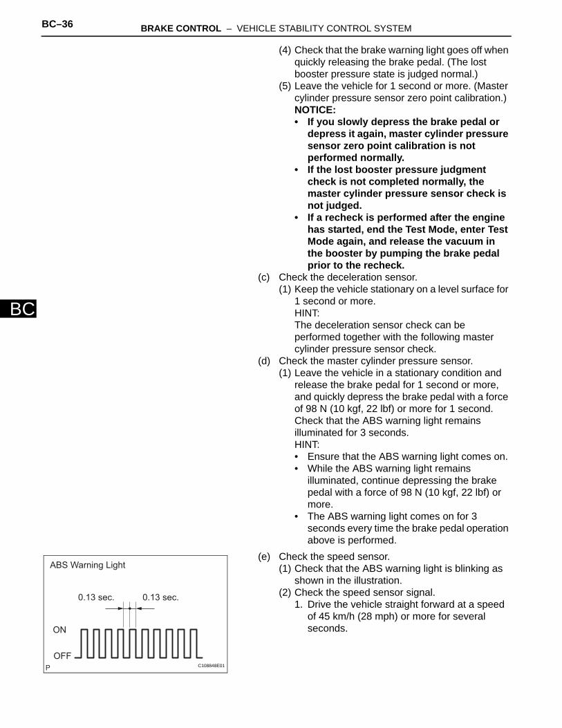
(6) Check that the ABS warning light and VSC warning light blink as shown in the illustration.HINT:If the ABS warning light and VSC warning warning light and multi information display and master caution indicator light do not blink, check the TS and CG terminal circuit, and ABS and VSC warning light circuits.
(7) Start the engine.(b) w/ 16-inch disc:
Check the lost booster pressure judgment and perform the master cylinder pressure sensor zero point calibration.NOTICE:Preform the check in the lost booster pressure state (negative pressure in the booster is depressurized).(1) Turn the ignition switch ON.(2) Check that the BRAKE warning light comes on
when depressing the brake pedal with a force of 59 N (6 kgf, 13.2 lbf) or more for 1 second or more. (The lost booster pressure state is judged normal.)
(3) Start the engine depressing the brake pedal with a force of 59 N (6 kgf, 13.2 lbf) or more for 1 second or more.
CG
TSDLC3
H100769E03
0.13 sec. 0.13 sec.
ON
OFF
Blinking Pattern in TEST MODE
C108848E14
Section Title See procedure
ABS Warning Light does not Come ON BC-138
VSC Warning Light does not Come ON BC-142
TS and CG Terminal Circuit BC-177
BC–36 BRAKE CONTROL – VEHICLE STABILITY CONTROL SYSTEM
BC
(4) Check that the brake warning light goes off when quickly releasing the brake pedal. (The lost booster pressure state is judged normal.)
(5) Leave the vehicle for 1 second or more. (Master cylinder pressure sensor zero point calibration.)NOTICE:• If you slowly depress the brake pedal or
depress it again, master cylinder pressure sensor zero point calibration is not performed normally.
• If the lost booster pressure judgment check is not completed normally, the master cylinder pressure sensor check is not judged.
• If a recheck is performed after the engine has started, end the Test Mode, enter Test Mode again, and release the vacuum in the booster by pumping the brake pedal prior to the recheck.
(c) Check the deceleration sensor.(1) Keep the vehicle stationary on a level surface for
1 second or more.HINT:The deceleration sensor check can be performed together with the following master cylinder pressure sensor check.
(d) Check the master cylinder pressure sensor.(1) Leave the vehicle in a stationary condition and
release the brake pedal for 1 second or more, and quickly depress the brake pedal with a force of 98 N (10 kgf, 22 lbf) or more for 1 second.Check that the ABS warning light remains illuminated for 3 seconds.HINT:• Ensure that the ABS warning light comes on.• While the ABS warning light remains
illuminated, continue depressing the brake pedal with a force of 98 N (10 kgf, 22 lbf) or more.
• The ABS warning light comes on for 3 seconds every time the brake pedal operation above is performed.
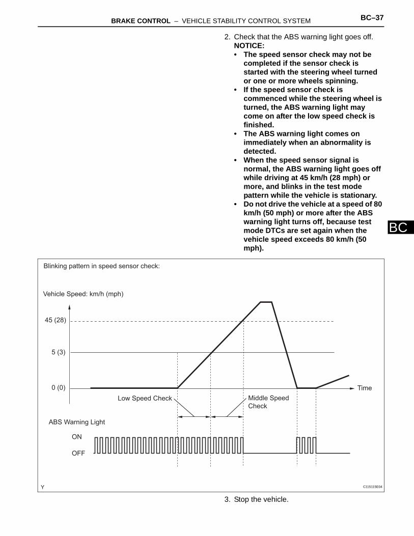
(e) Check the speed sensor.(1) Check that the ABS warning light is blinking as
shown in the illustration.(2) Check the speed sensor signal.
1. Drive the vehicle straight forward at a speed of 45 km/h (28 mph) or more for several seconds.
ABS Warning Light
0.13 sec. 0.13 sec.
ON
OFFC108848E01
BRAKE CONTROL – VEHICLE STABILITY CONTROL SYSTEM BC–37
BC
2. Check that the ABS warning light goes off.NOTICE:• The speed sensor check may not be
completed if the sensor check is started with the steering wheel turned or one or more wheels spinning.
• If the speed sensor check is commenced while the steering wheel is turned, the ABS warning light may come on after the low speed check is finished.
• The ABS warning light comes on immediately when an abnormality is detected.
• When the speed sensor signal is normal, the ABS warning light goes off while driving at 45 km/h (28 mph) or more, and blinks in the test mode pattern while the vehicle is stationary.
• Do not drive the vehicle at a speed of 80 km/h (50 mph) or more after the ABS warning light turns off, because test mode DTCs are set again when the vehicle speed exceeds 80 km/h (50 mph).
3. Stop the vehicle.
Vehicle Speed: km/h (mph)
ABS Warning Light
Time
ON
OFF
45 (28)
5 (3)
0 (0)
Low Speed Check Middle Speed
Check
Blinking pattern in speed sensor check:
C115115E04

BC–38 BRAKE CONTROL – VEHICLE STABILITY CONTROL SYSTEM
BC
(f) Check the yaw rate sensor.(1) Move the shift lever to P and set the parking
brake lever.(2) Check that the VSC warning light is blinking as
shown in the illustration.(3) Keep the vehicle stationary on a level surface for
1 second or more.
(4) Shift the shift lever to the D position and drive the vehicle at a speed of approximately 5 km/h (3 mph), and turn the steering wheel either to the left or right 90° or more to turn the vehicle through 180°.
(5) Stop the vehicle, move the shift lever into the P position, and then apply the parking brake.
(6) Check that the skid control buzzer sounds for 3 seconds.HINT:• If the skid control buzzer sounds, the signal
check has been completed normally.• If the skid control buzzer does not sound,
check the skid control buzzer circuit (see page BC-172).
• If the skid control buzzer still does not sound, there is a malfunction in the yaw rate sensor, so check for DTCs.
• Drive the vehicle in a 180° semi circle. At the end of the turn, the direction of the vehicle should be within 180 +-5° of its start position.
• Complete the vehicle turn within 20 seconds.• Do not spin the wheels.
(g) w/ Downhill assist control only:Check the downhill assist control operation switch.(1) Check that the VSC warning light is blinking as
shown in the illustration.(2) Check the downhill assist control switch.
1. Push the downhill assist control switch on.2. Push the downhill assist control switch off.
0.13 sec. 0.13 sec.
ON
OFF
Blinking Pattern in TEST MODE
C108848E14
Start Position
End Position
Within +-5
F002135E15
0.13 sec. 0.13 sec.
ON
OFF
Blinking Pattern in TEST MODE
C108848E14
BRAKE CONTROL – VEHICLE STABILITY CONTROL SYSTEM BC–39
BC
(h) w/ Auto LSD only:Check the end of the sensor.(1) When the sensor check is successfully
completed, the ABS warning light blinks in the test mode pattern when the vehicle is stopped, and goes off when the vehicle is driven.NOTICE:If the sensor check is not completed, the ABS warning light blinks even while the vehicle is driving and the ABS does not operate.
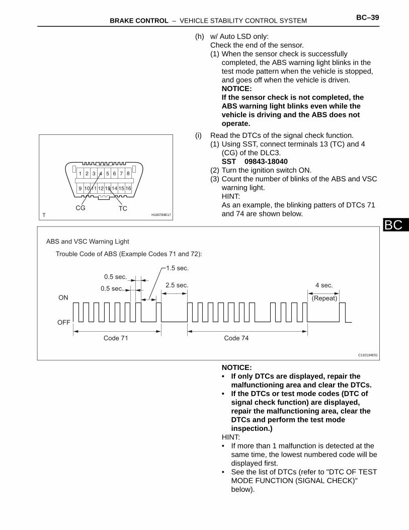
(i) Read the DTCs of the signal check function.(1) Using SST, connect terminals 13 (TC) and 4
(CG) of the DLC3.SST 09843-18040
(2) Turn the ignition switch ON.(3) Count the number of blinks of the ABS and VSC
warning light.HINT:As an example, the blinking patters of DTCs 71 and 74 are shown below.
NOTICE:• If only DTCs are displayed, repair the
malfunctioning area and clear the DTCs.• If the DTCs or test mode codes (DTC of
signal check function) are displayed, repair the malfunctioning area, clear the DTCs and perform the test mode inspection.)
HINT:• If more than 1 malfunction is detected at the
same time, the lowest numbered code will be displayed first.
• See the list of DTCs (refer to "DTC OF TEST MODE FUNCTION (SIGNAL CHECK)" below).
TCCGH100769E17
Trouble Code of ABS (Example Codes 71 and 72):
ON
OFF
Code 71 Code 74
2.5 sec.
1.5 sec.
0.5 sec.
0.5 sec.
4 sec.
(Repeat)
ABS and VSC Warning Light
C132134E01
BC–40 BRAKE CONTROL – VEHICLE STABILITY CONTROL SYSTEM
BC
• If all sensors are normal, a normal system code is output (the light comes on for 0.25 seconds at intervals of 0.25 seconds).
(4) After the check, disconnect SST from terminals 13 (TC) and 4 (CG) of the DLC3.
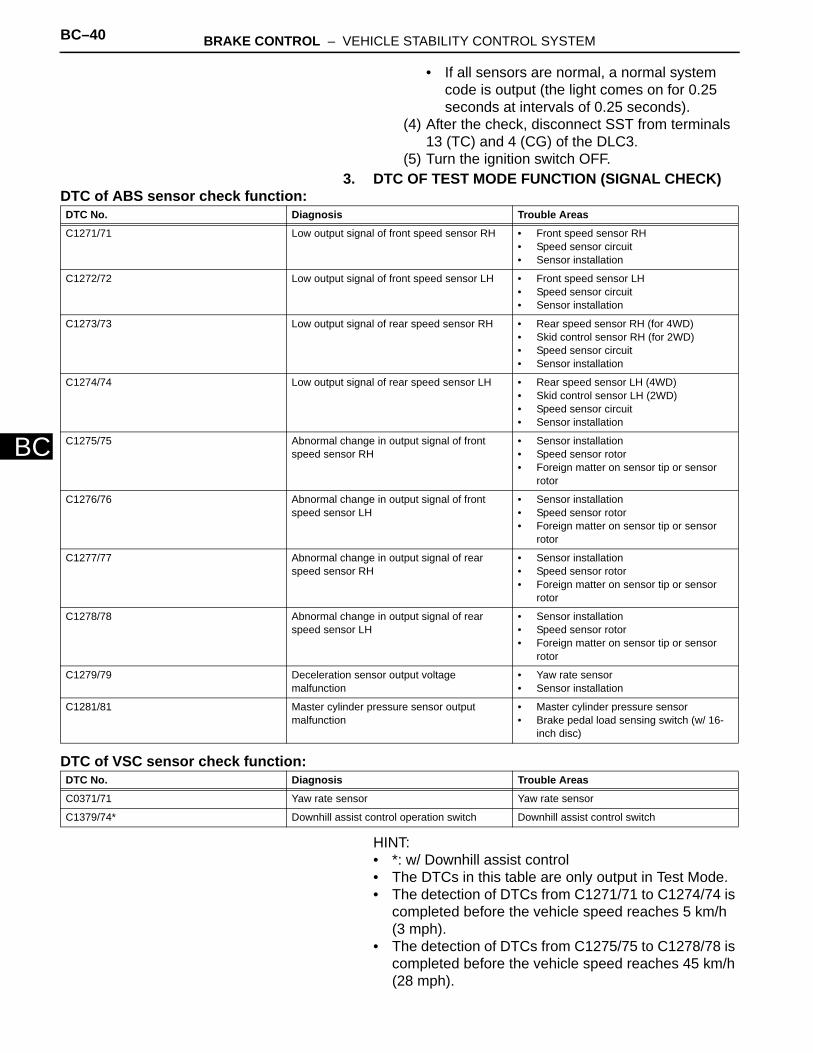
(5) Turn the ignition switch OFF.3. DTC OF TEST MODE FUNCTION (SIGNAL CHECK)
DTC of ABS sensor check function:
DTC of VSC sensor check function:
HINT:• *: w/ Downhill assist control• The DTCs in this table are only output in Test Mode.• The detection of DTCs from C1271/71 to C1274/74 is
completed before the vehicle speed reaches 5 km/h (3 mph).
• The detection of DTCs from C1275/75 to C1278/78 is completed before the vehicle speed reaches 45 km/h (28 mph).
DTC No. Diagnosis Trouble Areas
C1271/71 Low output signal of front speed sensor RH • Front speed sensor RH• Speed sensor circuit• Sensor installation
C1272/72 Low output signal of front speed sensor LH • Front speed sensor LH• Speed sensor circuit• Sensor installation
C1273/73 Low output signal of rear speed sensor RH • Rear speed sensor RH (for 4WD)• Skid control sensor RH (for 2WD)• Speed sensor circuit• Sensor installation
C1274/74 Low output signal of rear speed sensor LH • Rear speed sensor LH (4WD)• Skid control sensor LH (2WD)• Speed sensor circuit• Sensor installation
C1275/75 Abnormal change in output signal of front speed sensor RH
• Sensor installation• Speed sensor rotor• Foreign matter on sensor tip or sensor
rotor
C1276/76 Abnormal change in output signal of front speed sensor LH
• Sensor installation• Speed sensor rotor• Foreign matter on sensor tip or sensor
rotor
C1277/77 Abnormal change in output signal of rear speed sensor RH
• Sensor installation• Speed sensor rotor• Foreign matter on sensor tip or sensor
rotor
C1278/78 Abnormal change in output signal of rear speed sensor LH
• Sensor installation• Speed sensor rotor• Foreign matter on sensor tip or sensor
rotor
C1279/79 Deceleration sensor output voltage malfunction
• Yaw rate sensor• Sensor installation
C1281/81 Master cylinder pressure sensor output malfunction
• Master cylinder pressure sensor• Brake pedal load sensing switch (w/ 16-
inch disc)
DTC No. Diagnosis Trouble Areas
C0371/71 Yaw rate sensor Yaw rate sensor
C1379/74* Downhill assist control operation switch Downhill assist control switch

BRAKE CONTROL – VEHICLE STABILITY CONTROL SYSTEM BC–41
BC
• C1271/71 to C1274/74: The speed output from only one wheel is extremely low despite other wheel speed outputs reaching 5 km/h (3 mph).
• C1275/75 to C1278/78: The abnormal speed sensor output frequency is as shown in the illustration.Example
Normal
Abnormal
F100272E02
BC–42 BRAKE CONTROL – VEHICLE STABILITY CONTROL SYSTEM
BC
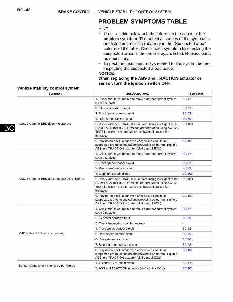
PROBLEM SYMPTOMS TABLEHINT:• Use the table below to help determine the cause of the
problem symptom. The potential causes of the symptoms are listed in order of probability in the "Suspected area" column of the table. Check each symptom by checking the suspected areas in the order they are listed. Replace parts as necessary.
• Inspect the fuses and relays related to this system before inspecting the suspected areas below.
NOTICE:When replacing the ABS and TRACTION actuator or sensor, turn the ignition switch OFF.
Vehicle stability control systemSymptom Suspected area See page
ABS, BA and/or EBD does not operate
1. Check for DTCs again and make sure that normal system code displayed
BC-47
2. IG power source circuit BC-99
3. Front speed sensor circuit BC-62
4. Rear speed sensor circuit BC-69
5. Check ABS and TRACTION actuator using intelligent tester (Check ABS and TRACTION actuator operation using ACTIVE TEST function). If abnormal, check hydraulic circuit for leakage.
BC-180
6. If symptoms still occur even after above circuits in suspected areas inspected and proved to be normal, replace ABS and TRACTION actuator (skid control ECU)
BC-181
ABS, BA and/or EBD does not operate efficiently
1. Check for DTCs again and make sure that normal system code displayed
BC-47
2. Front speed sensor circuit BC-62
3. Rear speed sensor circuit BC-69
4. Stop light switch circuit BC-105
5. Check ABS and TRACTION actuator using intelligent tester (Check ABS and TRACTION actuator operation using ACTIVE TEST function). If abnormal, check hydraulic circuit for leakage.
BC-180
6. If symptoms still occur even after above circuits in suspected areas inspected and proved to be normal, replace ABS and TRACTION actuator (skid control ECU)
BC-181
VSC and/or TRC does not operate
1. Check for DTCs again and make sure that normal system code displayed
BC-47
2. IG power source circuit BC-99
3. Check hydraulic circuit for leakage -
4. Front speed sensor circuit BC-62
5. Rear speed sensor circuit BC-69
6. Yaw rate sensor circuit BC-96
7. Steering angle sensor circuit BC-92
8. If symptoms still occur even after above circuits in suspected areas inspected and proved to be normal, replace ABS and TRACTION actuator (skid control ECU)
BC-181
Sensor signal check cannot be performed1. TS and CG terminal circuit BC-177
2. ABS and TRACTION actuator (skid control ECU) BC-181
BRAKE CONTROL – VEHICLE STABILITY CONTROL SYSTEM BC–43
BC
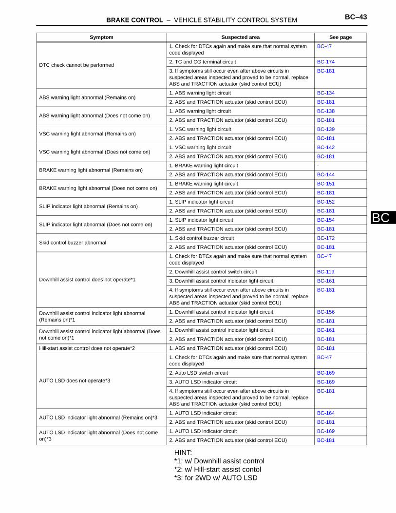
HINT:*1: w/ Downhill assist control*2: w/ Hill-start assist contol*3: for 2WD w/ AUTO LSD
DTC check cannot be performed
1. Check for DTCs again and make sure that normal system code displayed
BC-47
2. TC and CG terminal circuit BC-174
3. If symptoms still occur even after above circuits in suspected areas inspected and proved to be normal, replace ABS and TRACTION actuator (skid control ECU)
BC-181
ABS warning light abnormal (Remains on)1. ABS warning light circuit BC-134
2. ABS and TRACTION actuator (skid control ECU) BC-181
ABS warning light abnormal (Does not come on)1. ABS warning light circuit BC-138
2. ABS and TRACTION actuator (skid control ECU) BC-181
VSC warning light abnormal (Remains on)1. VSC warning light circuit BC-139
2. ABS and TRACTION actuator (skid control ECU) BC-181
VSC warning light abnormal (Does not come on)1. VSC warning light circuit BC-142
2. ABS and TRACTION actuator (skid control ECU) BC-181
BRAKE warning light abnormal (Remains on)1. BRAKE warning light circuit -
2. ABS and TRACTION actuator (skid control ECU) BC-144
BRAKE warning light abnormal (Does not come on)1. BRAKE warning light circuit BC-151
2. ABS and TRACTION actuator (skid control ECU) BC-181
SLIP indicator light abnormal (Remains on)1. SLIP indicator light circuit BC-152
2. ABS and TRACTION actuator (skid control ECU) BC-181
SLIP indicator light abnormal (Does not come on)1. SLIP indicator light circuit BC-154
2. ABS and TRACTION actuator (skid control ECU) BC-181
Skid control buzzer abnormal1. Skid control buzzer circuit BC-172
2. ABS and TRACTION actuator (skid control ECU) BC-181
Downhill assist control does not operate*1
1. Check for DTCs again and make sure that normal system code displayed
BC-47
2. Downhill assist control switch circuit BC-119
3. Downhill assist control indicator light circuit BC-161
4. If symptoms still occur even after above circuits in suspected areas inspected and proved to be normal, replace ABS and TRACTION actuator (skid control ECU)
BC-181
Downhill assist control indicator light abnormal (Remains on)*1
1. Downhill assist control indicator light circuit BC-156
2. ABS and TRACTION actuator (skid control ECU) BC-181
Downhill assist control indicator light abnormal (Does not come on)*1
1. Downhill assist control indicator light circuit BC-161
2. ABS and TRACTION actuator (skid control ECU) BC-181
Hill-start assist control does not operate*2 1. ABS and TRACTION actuator (skid control ECU) BC-181
AUTO LSD does not operate*3
1. Check for DTCs again and make sure that normal system code displayed
BC-47
2. Auto LSD switch circuit BC-169
3. AUTO LSD indicator circuit BC-169
4. If symptoms still occur even after above circuits in suspected areas inspected and proved to be normal, replace ABS and TRACTION actuator (skid control ECU)
BC-181
AUTO LSD indicator light abnormal (Remains on)*31. AUTO LSD indicator circuit BC-164
2. ABS and TRACTION actuator (skid control ECU) BC-181
AUTO LSD indicator light abnormal (Does not come on)*3
1. AUTO LSD indicator circuit BC-169
2. ABS and TRACTION actuator (skid control ECU) BC-181
Symptom Suspected area See page

BC–44 BRAKE CONTROL – VEHICLE STABILITY CONTROL SYSTEM
BC
TERMINALS OF ECU1. SKID CONTROL ECU
HINT:*1: w/ 16-inch disc*2: w/ Downhill assist control*3: for 2WD (w/ AUTO LSD)
Symbols (Terminal No.) Terminal Description
GND2 (A19-1) Motor ground
BM (A19-2) Motor relay input
FR+ (A19-3) Front RH wheel speed sensor power supply
FL- (A19-4) Front LH wheel speed signal input
RR+ (A19-5) Rear RH wheel speed signal power supply
RL- (A19-6) Rear LH wheel speed signal input
FSW+ (A19-7)*1 Brake pedal load sensing switch input
CANH (A19-11) CAN communication line H
SP1 (A19-12) Speed signal output for combination meter
MRF (A19-14) Fail safe motor relay output
MR (A19-15) Motor relay output
STPO (A19-16) Stop light relay output
FR- (A19-17) Front RH wheel speed signal input
FL+ (A19-18) Front LH wheel speed sensor power supply
RR- (A19-19) Rear RH wheel speed signal input
RL+ (A19-20) Rear LH wheel speed sensor power supply
STP2 (A19-21) Stop light relay input
TS (A19-24) Sensor diagnosis check input
CANL (A19-25) CAN communication line L
STP1 (A19-27) Stop light switch input
HDCS (A19-28)*2 Downhill assist control switch input
+BS (A19-31) Solenoid valve power supply
GND1 (A19-32) Skid control ECU ground
CSW (A19-43)*3 AUTO LSD switch input
R+ (A19-45) Power supply for motor relay
IG1 (A19-46) ECU power supply
A19
C110610E04
BRAKE CONTROL – VEHICLE STABILITY CONTROL SYSTEM BC–45
BC
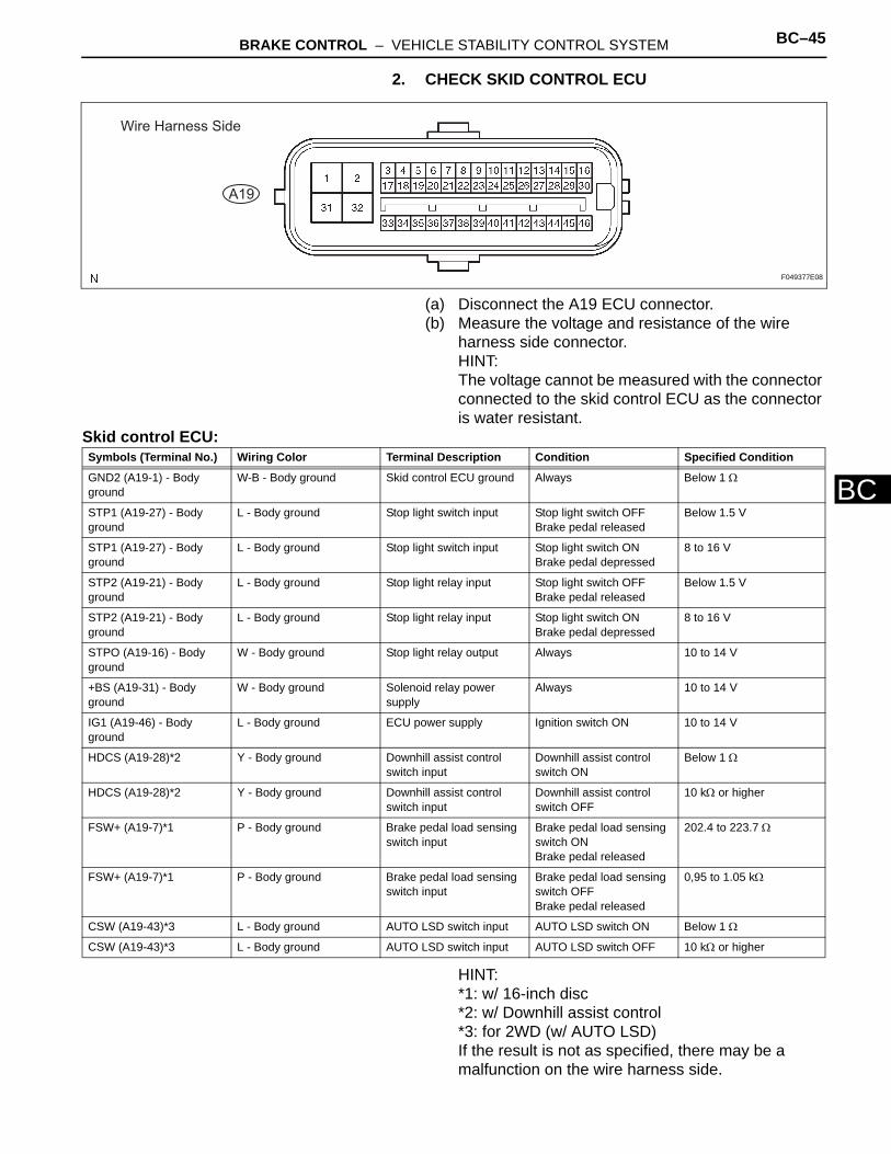
2. CHECK SKID CONTROL ECU
(a) Disconnect the A19 ECU connector.(b) Measure the voltage and resistance of the wire
harness side connector.HINT:The voltage cannot be measured with the connector connected to the skid control ECU as the connector is water resistant.
Skid control ECU:
HINT:*1: w/ 16-inch disc*2: w/ Downhill assist control*3: for 2WD (w/ AUTO LSD)If the result is not as specified, there may be a malfunction on the wire harness side.
A19
Wire Harness Side
F049377E08
Symbols (Terminal No.) Wiring Color Terminal Description Condition Specified Condition
GND2 (A19-1) - Body ground
W-B - Body ground Skid control ECU ground Always Below 1 Ω
STP1 (A19-27) - Body ground
L - Body ground Stop light switch input Stop light switch OFFBrake pedal released
Below 1.5 V
STP1 (A19-27) - Body ground
L - Body ground Stop light switch input Stop light switch ONBrake pedal depressed
8 to 16 V
STP2 (A19-21) - Body ground
L - Body ground Stop light relay input Stop light switch OFFBrake pedal released
Below 1.5 V
STP2 (A19-21) - Body ground
L - Body ground Stop light relay input Stop light switch ONBrake pedal depressed
8 to 16 V
STPO (A19-16) - Body ground
W - Body ground Stop light relay output Always 10 to 14 V
+BS (A19-31) - Body ground
W - Body ground Solenoid relay power supply
Always 10 to 14 V
IG1 (A19-46) - Body ground
L - Body ground ECU power supply Ignition switch ON 10 to 14 V
HDCS (A19-28)*2 Y - Body ground Downhill assist control switch input
Downhill assist control switch ON
Below 1 Ω
HDCS (A19-28)*2 Y - Body ground Downhill assist control switch input
Downhill assist control switch OFF
10 kΩ or higher
FSW+ (A19-7)*1 P - Body ground Brake pedal load sensing switch input
Brake pedal load sensing switch ONBrake pedal released
202.4 to 223.7 Ω
FSW+ (A19-7)*1 P - Body ground Brake pedal load sensing switch input
Brake pedal load sensing switch OFFBrake pedal released
0,95 to 1.05 kΩ
CSW (A19-43)*3 L - Body ground AUTO LSD switch input AUTO LSD switch ON Below 1 Ω
CSW (A19-43)*3 L - Body ground AUTO LSD switch input AUTO LSD switch OFF 10 kΩ or higher
BC–46 BRAKE CONTROL – VEHICLE STABILITY CONTROL SYSTEM
BC
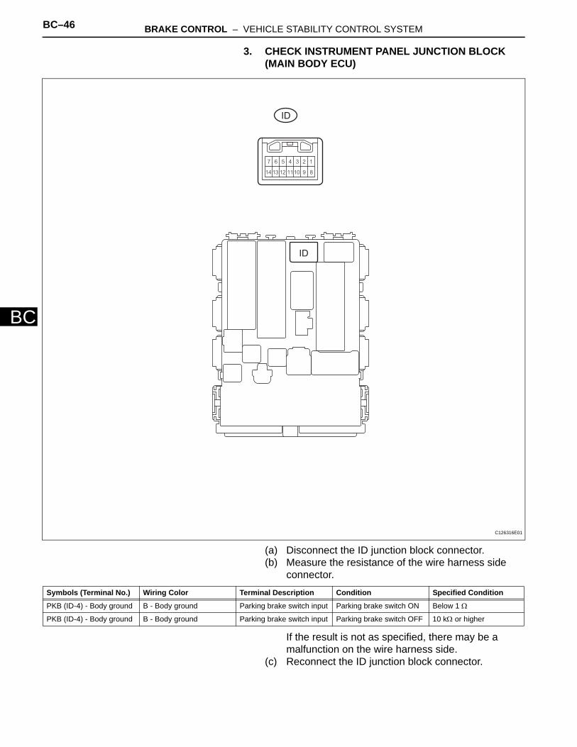
3. CHECK INSTRUMENT PANEL JUNCTION BLOCK (MAIN BODY ECU)
(a) Disconnect the ID junction block connector.(b) Measure the resistance of the wire harness side
connector.
If the result is not as specified, there may be a malfunction on the wire harness side.
(c) Reconnect the ID junction block connector.
ID
ID
C126316E01
Symbols (Terminal No.) Wiring Color Terminal Description Condition Specified Condition
PKB (ID-4) - Body ground B - Body ground Parking brake switch input Parking brake switch ON Below 1 Ω
PKB (ID-4) - Body ground B - Body ground Parking brake switch input Parking brake switch OFF 10 kΩ or higher

BRAKE CONTROL – VEHICLE STABILITY CONTROL SYSTEM BC–47
BC
(d) Measure the voltage of the wire harness side connector.
If the result is not as specified, the junction block (ECU) may be a malfunction.
Symbols (Terminal No.) Wiring Color Terminal Description Condition Specified Condition
PKB (ID-4) - Body ground B - Body ground Parking brake switch input Parking brake switch ON Below 1 V
PKB (ID-4) - Body ground B - Body ground Parking brake switch input Parking brake switch OFF 10 to 14 V
BC–48 BRAKE CONTROL – VEHICLE STABILITY CONTROL SYSTEM
BC
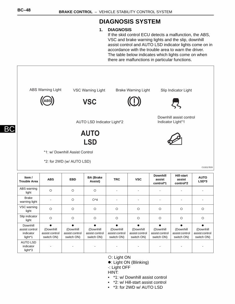
DIAGNOSIS SYSTEM1. DIAGNOSIS
If the skid control ECU detects a malfunction, the ABS, VSC and brake warning lights and the slip, downhill assist control and AUTO LSD indicator lights come on in accordance with the trouble area to warn the driver.The table below indicates which lights come on when there are malfunctions in particular functions.
: Light ON: Light ON (Blinking)
-: Light OFFHINT:• *1: w/ Downhill assist control• *2: w/ Hill-start assist control• *3: for 2WD w/ AUTO LSD
Item / Trouble Area ABS EBD BA (Brake
Assist) TRC VSCDownhill
assist control*1
Hill-start assist
control*2
AUTO LSD*3
ABS warning light - - - - -
Brake warning light - *4 - - - - -
VSC warning light
Slip indicator light
Downhill assist control
indicator light*1
(Downhill assist control switch ON)
(Downhill assist control switch ON)
(Downhill assist control switch ON)
(Downhill assist control switch ON)
(Downhill assist control switch ON)
(Downhill assist control switch ON)
(Downhill assist control switch ON)
(Downhill assist control switch ON)
AUTO LSD indicator light*3
- - - - - - - -
VSC
AUTO
LSD
ABS Warning Light VSC Warning Light Brake Warning Light Slip Indicator Light
AUTO LSD Indicator Light*2
Downhill assist control
Indicator Light*1
*2: for 2WD (w/ AUTO LSD)
*1: w/ Downhill Assist Control
C132117E03

BRAKE CONTROL – VEHICLE STABILITY CONTROL SYSTEM BC–49
BC
• *4: w/ 16-inch disc• The DTCs can be read by connecting SST (09843-
18040) between the TC and CG terminals of the DLC3 and observing the blinking pattern of the ABS and VSC warning lights, or by using an intelligent tester (see page BC-47).
• This system has a sensor signal check function (see page BC-28).
2. CHECK WARNING LIGHT AND INDICATOR LIGHT(a) Release the parking brake lever.
NOTICE:Before releasing the parking brake lever, set chocks to hold the vehicle for safety.HINT:When the parking brake is applied or the brake fluid level is low, the brake warning light comes on.
(b) When the ignition switch is turned ON, check that the ABS, VSC and brake warning lights and the slip, downhill assist control and AUTO LSD indicator lights come on and go off in about 3 seconds.
HINT:If the warning lights do not illuminate, confirm whether the bulbs have burned out, and also check for CAN communication system DTCs, since the skid control ECU and combination meter are connected by the CAN communication line.If the warning light remains on, perform relevant troubleshooting procedures. The relevant troubleshooting procedures are in the sections listed in the table below.
VSC
AUTO
LSD
ABS Warning Light VSC Warning Light Brake Warning Light Slip Indicator Light
AUTO LSD Indicator Light*2
Downhill assist control
Indicator Light*1
*2: for 2WD (w/ AUTO LSD)
*1: w/ Downhill Assist Control
C132117E03
Section Title See procedure
ABS Warning Light Remains ON BC-134

BC–50 BRAKE CONTROL – VEHICLE STABILITY CONTROL SYSTEM
BC
DTC CHECK / CLEAR1. CHECK DTC (When Using Intelligent Tester)
(a) Connect the intelligent tester (with CAN VIM) to the DLC3.
(b) Turn the ignition switch ON.(c) Turn the tester on.(d) Read the DTCs by following the prompts on the
tester screen.HINT:Refer to the intelligent tester operator's manual for further details.
2. CLEAR DTC (When Using Intelligent Tester)(a) Connect the intelligent tester (with CAN VIM) to the
DLC3.(b) Turn the ignition switch ON.(c) Turn the tester on.(d) Operate the intelligent tester to clear the codes.
HINT:Refer to the intelligent tester operator's manual for further details.
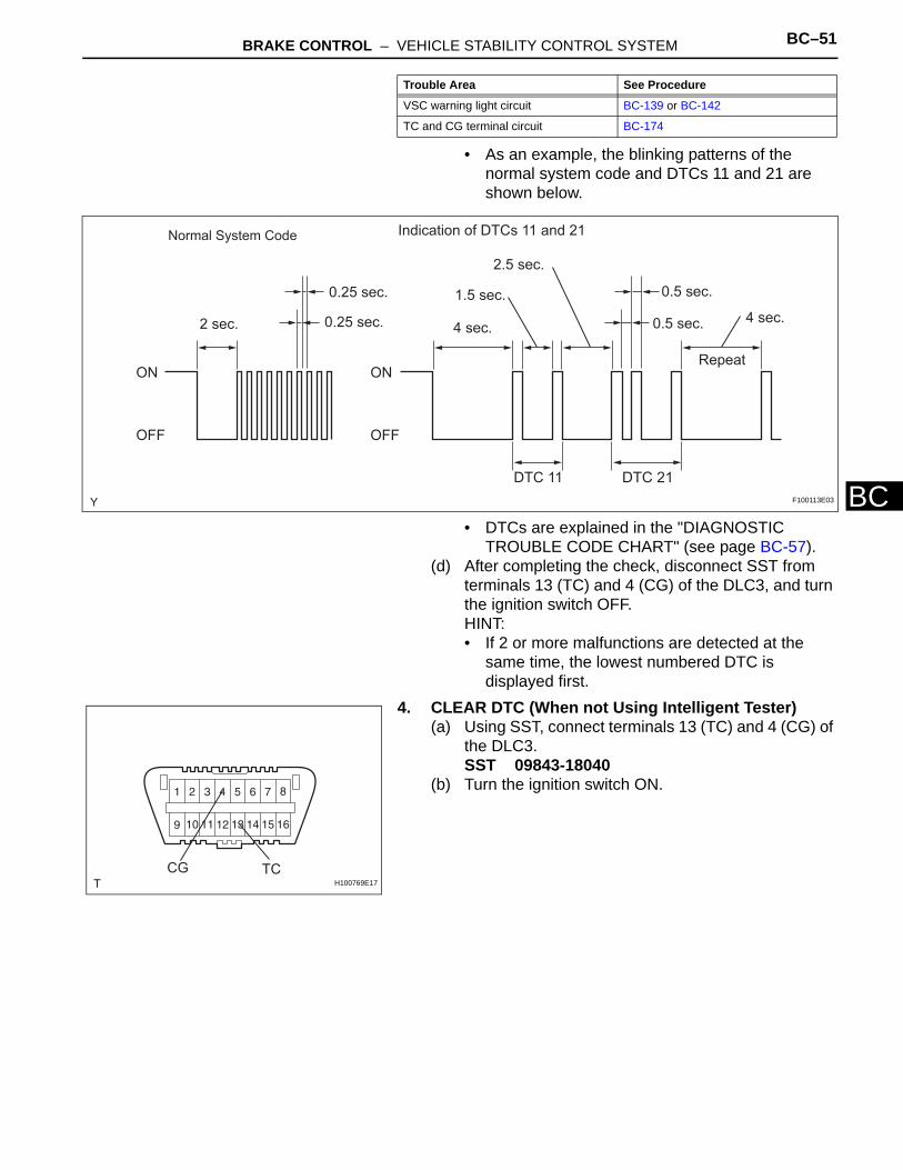
3. CHECK DTC (When not Using Intelligent Tester)(a) Using SST, connect terminals 13 (TC) and 4 (CG) of
the DLC3.SST 09843-18040
(b) Turn the ignition switch ON.(c) Read DTCs from the ABS warning light on the
combination meter.HINT:• If the ABS warning light does not blink, perform
relevant troubleshooting procedures. The relevant troubleshooting procedures are in the sections listed in the table below.
VSC Warning Light Remains ON BC-139
Brake Warning Light Remains ON BC-144
Slip Indicator Light Remains ON BC-152
Downhill assist control Indicator Light Remains ON BC-156
AUTO LSD Indicator Light Remains ON BC-164
Section Title See procedure
Intelligent Tester
CAN VIM
DLC3
B127989E01
Intelligent Tester
CAN VIM
DLC3
B127989E01
TCCGH100769E17
Trouble Area See Procedure
ABS warning light circuit BC-134 or BC-138
BRAKE CONTROL – VEHICLE STABILITY CONTROL SYSTEM BC–51
BC
• As an example, the blinking patterns of the normal system code and DTCs 11 and 21 are shown below.
• DTCs are explained in the "DIAGNOSTIC TROUBLE CODE CHART" (see page BC-57).
(d) After completing the check, disconnect SST from terminals 13 (TC) and 4 (CG) of the DLC3, and turn the ignition switch OFF.HINT:• If 2 or more malfunctions are detected at the
same time, the lowest numbered DTC is displayed first.
4. CLEAR DTC (When not Using Intelligent Tester)(a) Using SST, connect terminals 13 (TC) and 4 (CG) of
the DLC3.SST 09843-18040
(b) Turn the ignition switch ON.
VSC warning light circuit BC-139 or BC-142
TC and CG terminal circuit BC-174
Trouble Area See Procedure
Normal System Code Indication of DTCs 11 and 21
0.25 sec.
0.25 sec.2 sec.
ON
OFF
ON
OFF
2.5 sec.
1.5 sec.
4 sec.
0.5 sec.
0.5 sec. 4 sec.
Repeat
DTC 11 DTC 21
F100113E03
TCCGH100769E17
BC–52 BRAKE CONTROL – VEHICLE STABILITY CONTROL SYSTEM
BC
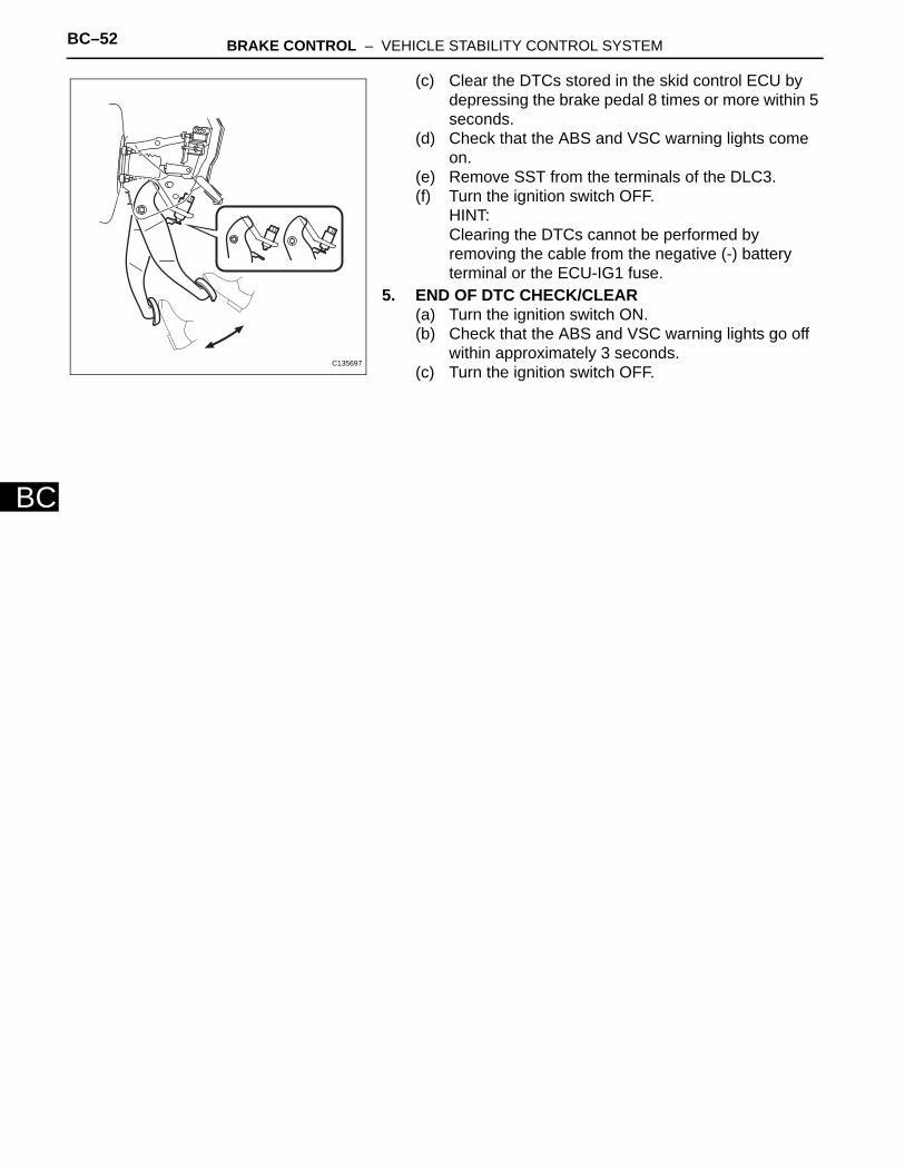
(c) Clear the DTCs stored in the skid control ECU by depressing the brake pedal 8 times or more within 5 seconds.
(d) Check that the ABS and VSC warning lights come on.
(e) Remove SST from the terminals of the DLC3.(f) Turn the ignition switch OFF.
HINT:Clearing the DTCs cannot be performed by removing the cable from the negative (-) battery terminal or the ECU-IG1 fuse.
5. END OF DTC CHECK/CLEAR(a) Turn the ignition switch ON.(b) Check that the ABS and VSC warning lights go off
within approximately 3 seconds.(c) Turn the ignition switch OFF.
C135697
BRAKE CONTROL – VEHICLE STABILITY CONTROL SYSTEM BC–53
BC
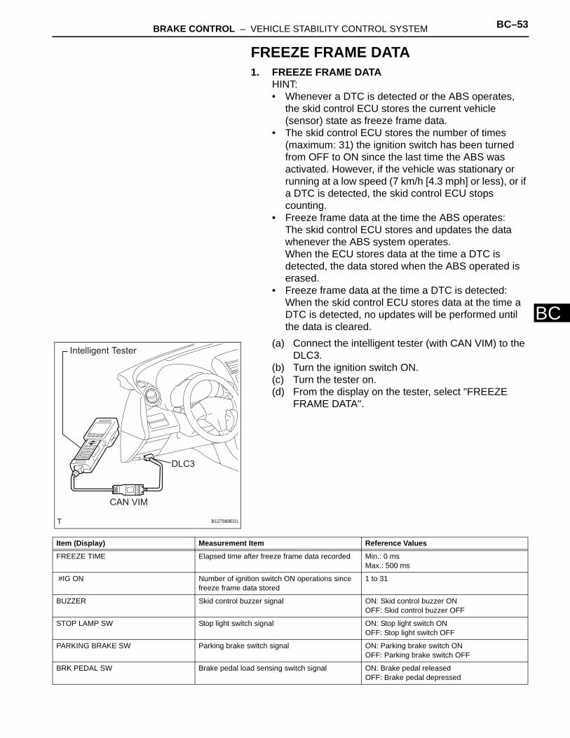
FREEZE FRAME DATA1. FREEZE FRAME DATA
HINT:• Whenever a DTC is detected or the ABS operates,
the skid control ECU stores the current vehicle (sensor) state as freeze frame data.
• The skid control ECU stores the number of times (maximum: 31) the ignition switch has been turned from OFF to ON since the last time the ABS was activated. However, if the vehicle was stationary or running at a low speed (7 km/h [4.3 mph] or less), or if a DTC is detected, the skid control ECU stops counting.
• Freeze frame data at the time the ABS operates:The skid control ECU stores and updates the data whenever the ABS system operates.When the ECU stores data at the time a DTC is detected, the data stored when the ABS operated is erased.
• Freeze frame data at the time a DTC is detected:When the skid control ECU stores data at the time a DTC is detected, no updates will be performed until the data is cleared.
(a) Connect the intelligent tester (with CAN VIM) to the DLC3.
(b) Turn the ignition switch ON.(c) Turn the tester on.(d) From the display on the tester, select "FREEZE
FRAME DATA".
Intelligent Tester
CAN VIM
DLC3
B127989E01
Item (Display) Measurement Item Reference Values
FREEZE TIME Elapsed time after freeze frame data recorded Min.: 0 msMax.: 500 ms
#IG ON Number of ignition switch ON operations since freeze frame data stored
1 to 31
BUZZER Skid control buzzer signal ON: Skid control buzzer ONOFF: Skid control buzzer OFF
STOP LAMP SW Stop light switch signal ON: Stop light switch ONOFF: Stop light switch OFF
PARKING BRAKE SW Parking brake switch signal ON: Parking brake switch ONOFF: Parking brake switch OFF
BRK PEDAL SW Brake pedal load sensing switch signal ON: Brake pedal releasedOFF: Brake pedal depressed
BC–54 BRAKE CONTROL – VEHICLE STABILITY CONTROL SYSTEM
BC
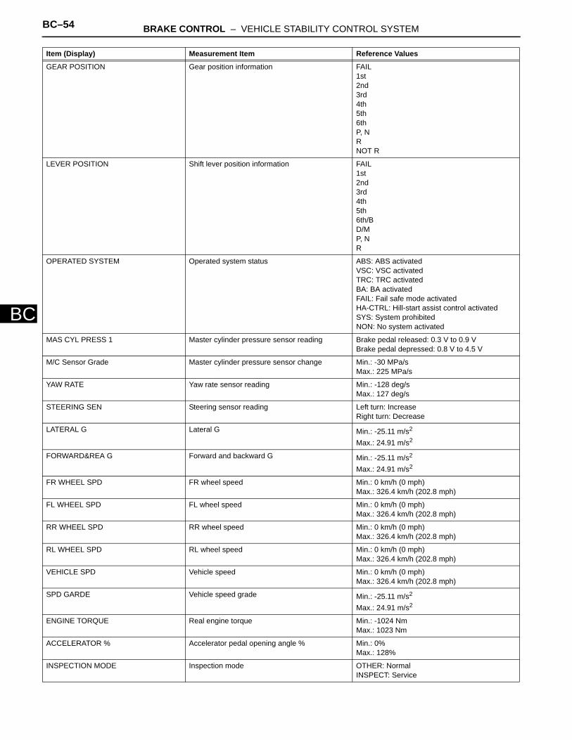
GEAR POSITION Gear position information FAIL1st2nd3rd4th5th6thP, NRNOT R
LEVER POSITION Shift lever position information FAIL1st2nd3rd4th5th6th/BD/MP, NR
OPERATED SYSTEM Operated system status ABS: ABS activatedVSC: VSC activatedTRC: TRC activatedBA: BA activatedFAIL: Fail safe mode activatedHA-CTRL: Hill-start assist control activatedSYS: System prohibitedNON: No system activated
MAS CYL PRESS 1 Master cylinder pressure sensor reading Brake pedal released: 0.3 V to 0.9 VBrake pedal depressed: 0.8 V to 4.5 V
M/C Sensor Grade Master cylinder pressure sensor change Min.: -30 MPa/sMax.: 225 MPa/s
YAW RATE Yaw rate sensor reading Min.: -128 deg/sMax.: 127 deg/s
STEERING SEN Steering sensor reading Left turn: IncreaseRight turn: Decrease
LATERAL G Lateral G Min.: -25.11 m/s2
Max.: 24.91 m/s2
FORWARD&REA G Forward and backward G Min.: -25.11 m/s2
Max.: 24.91 m/s2
FR WHEEL SPD FR wheel speed Min.: 0 km/h (0 mph)Max.: 326.4 km/h (202.8 mph)
FL WHEEL SPD FL wheel speed Min.: 0 km/h (0 mph)Max.: 326.4 km/h (202.8 mph)
RR WHEEL SPD RR wheel speed Min.: 0 km/h (0 mph)Max.: 326.4 km/h (202.8 mph)
RL WHEEL SPD RL wheel speed Min.: 0 km/h (0 mph)Max.: 326.4 km/h (202.8 mph)
VEHICLE SPD Vehicle speed Min.: 0 km/h (0 mph)Max.: 326.4 km/h (202.8 mph)
SPD GARDE Vehicle speed grade Min.: -25.11 m/s2
Max.: 24.91 m/s2
ENGINE TORQUE Real engine torque Min.: -1024 NmMax.: 1023 Nm
ACCELERATOR % Accelerator pedal opening angle % Min.: 0%Max.: 128%
INSPECTION MODE Inspection mode OTHER: NormalINSPECT: Service
Item (Display) Measurement Item Reference Values
BRAKE CONTROL – VEHICLE STABILITY CONTROL SYSTEM BC–55
BC
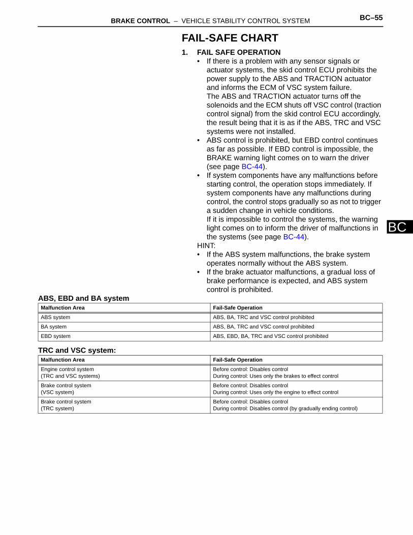
FAIL-SAFE CHART1. FAIL SAFE OPERATION
• If there is a problem with any sensor signals or actuator systems, the skid control ECU prohibits the power supply to the ABS and TRACTION actuator and informs the ECM of VSC system failure.The ABS and TRACTION actuator turns off the solenoids and the ECM shuts off VSC control (traction control signal) from the skid control ECU accordingly, the result being that it is as if the ABS, TRC and VSC systems were not installed.
• ABS control is prohibited, but EBD control continues as far as possible. If EBD control is impossible, the BRAKE warning light comes on to warn the driver (see page BC-44).
• If system components have any malfunctions before starting control, the operation stops immediately. If system components have any malfunctions during control, the control stops gradually so as not to trigger a sudden change in vehicle conditions.If it is impossible to control the systems, the warning light comes on to inform the driver of malfunctions in the systems (see page BC-44).
HINT:• If the ABS system malfunctions, the brake system
operates normally without the ABS system.• If the brake actuator malfunctions, a gradual loss of
brake performance is expected, and ABS system control is prohibited.
ABS, EBD and BA system
TRC and VSC system:
Malfunction Area Fail-Safe Operation
ABS system ABS, BA, TRC and VSC control prohibited
BA system ABS, BA, TRC and VSC control prohibited
EBD system ABS, EBD, BA, TRC and VSC control prohibited
Malfunction Area Fail-Safe Operation
Engine control system(TRC and VSC systems)
Before control: Disables controlDuring control: Uses only the brakes to effect control
Brake control system(VSC system)
Before control: Disables controlDuring control: Uses only the engine to effect control
Brake control system(TRC system)
Before control: Disables controlDuring control: Disables control (by gradually ending control)
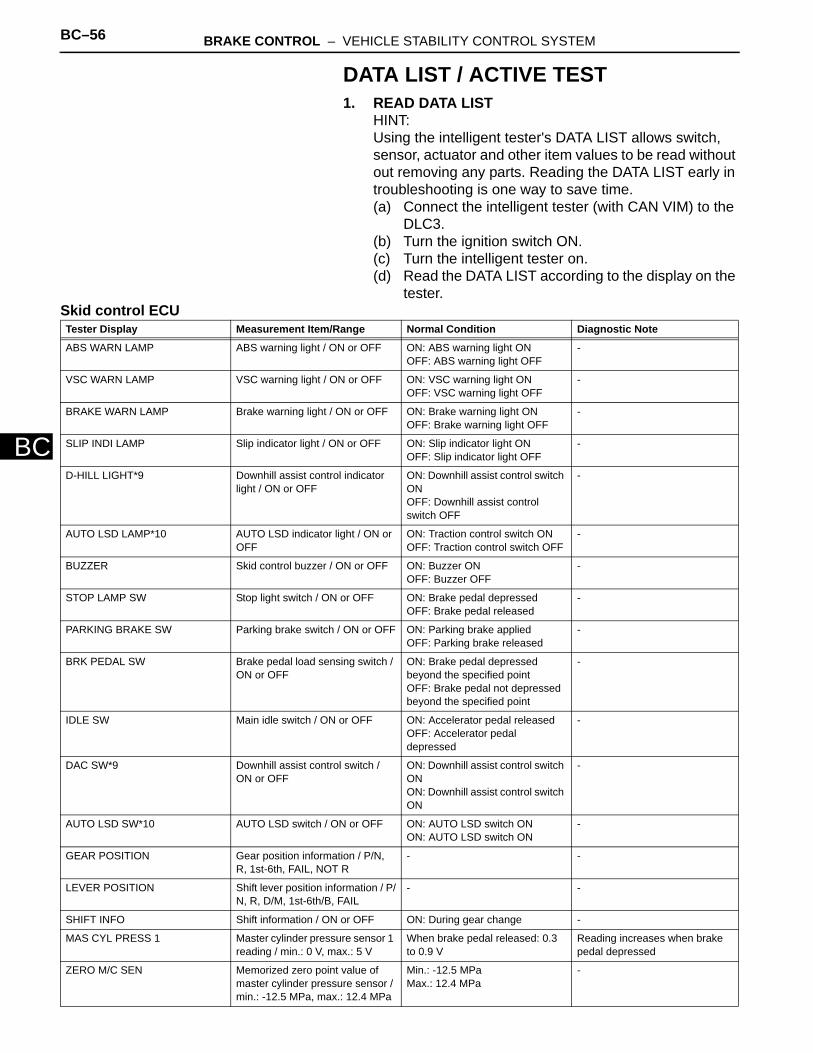
BC–56 BRAKE CONTROL – VEHICLE STABILITY CONTROL SYSTEM
BC
DATA LIST / ACTIVE TEST1. READ DATA LIST
HINT:Using the intelligent tester's DATA LIST allows switch, sensor, actuator and other item values to be read without out removing any parts. Reading the DATA LIST early in troubleshooting is one way to save time.(a) Connect the intelligent tester (with CAN VIM) to the
DLC3.(b) Turn the ignition switch ON.(c) Turn the intelligent tester on.(d) Read the DATA LIST according to the display on the
tester.Skid control ECUTester Display Measurement Item/Range Normal Condition Diagnostic Note
ABS WARN LAMP ABS warning light / ON or OFF ON: ABS warning light ONOFF: ABS warning light OFF
-
VSC WARN LAMP VSC warning light / ON or OFF ON: VSC warning light ONOFF: VSC warning light OFF
-
BRAKE WARN LAMP Brake warning light / ON or OFF ON: Brake warning light ONOFF: Brake warning light OFF
-
SLIP INDI LAMP Slip indicator light / ON or OFF ON: Slip indicator light ONOFF: Slip indicator light OFF
-
D-HILL LIGHT*9 Downhill assist control indicator light / ON or OFF
ON: Downhill assist control switch ONOFF: Downhill assist control switch OFF
-
AUTO LSD LAMP*10 AUTO LSD indicator light / ON or OFF
ON: Traction control switch ONOFF: Traction control switch OFF
-
BUZZER Skid control buzzer / ON or OFF ON: Buzzer ONOFF: Buzzer OFF
-
STOP LAMP SW Stop light switch / ON or OFF ON: Brake pedal depressedOFF: Brake pedal released
-
PARKING BRAKE SW Parking brake switch / ON or OFF ON: Parking brake appliedOFF: Parking brake released
-
BRK PEDAL SW Brake pedal load sensing switch / ON or OFF
ON: Brake pedal depressed beyond the specified pointOFF: Brake pedal not depressed beyond the specified point
-
IDLE SW Main idle switch / ON or OFF ON: Accelerator pedal releasedOFF: Accelerator pedal depressed
-
DAC SW*9 Downhill assist control switch / ON or OFF
ON: Downhill assist control switch ONON: Downhill assist control switch ON
-
AUTO LSD SW*10 AUTO LSD switch / ON or OFF ON: AUTO LSD switch ONON: AUTO LSD switch ON
-
GEAR POSITION Gear position information / P/N, R, 1st-6th, FAIL, NOT R
- -
LEVER POSITION Shift lever position information / P/N, R, D/M, 1st-6th/B, FAIL
- -
SHIFT INFO Shift information / ON or OFF ON: During gear change -
MAS CYL PRESS 1 Master cylinder pressure sensor 1 reading / min.: 0 V, max.: 5 V
When brake pedal released: 0.3 to 0.9 V
Reading increases when brake pedal depressed
ZERO M/C SEN Memorized zero point value of master cylinder pressure sensor / min.: -12.5 MPa, max.: 12.4 MPa
Min.: -12.5 MPaMax.: 12.4 MPa
-

BRAKE CONTROL – VEHICLE STABILITY CONTROL SYSTEM BC–57
BC
DECELERAT SEN Deceleration sensor 1 reading / min.: -18.52 m/s2, max.: 18.39 m/s2
Min.: -18.52 m/s2
Max.: 18.39 m/s2
-
ZERO DECELERAT Memorized zero point value of deceleration sensor 1 / min.: -25.11 m/s2, max.: 24.91 m/s2
Min.: -25.11 m/s2
Max.: 24.91 m/s2
-
DECELERAT SEN 2 Deceleration sensor 2 reading / min.: -18.52 m/s2, max.: 18.39 m/s2
Min.: -18.52 m/s2
Max.: 18.39 m/s2
-
ZERO DECELERAT 2 Memorized zero point value of deceleration sensor 2 / min.: -25.11 m/s2, max.: 24.91 m/s2
Min.: -25.11 m/s2
Max.: 24.91 m/s2
-
YAW RATE SENS 1 Yaw rate sensor 1 reading / min.: -128 deg/s, max.: 127 deg/s
Min.: -128 deg/sMax.: 127 deg/s
-
YAW RATE SENS 2 Yaw rate sensor 2 reading / min.: -128 deg/s, max.: 127 deg/s
Min.: -128 deg/sMax.: 127 deg/s
-
ZERO YAW RATE Memorized zero point value of yaw rate sensor 1 / min.: -128 deg/s, max.: 127 deg/s
Min.: -128 deg/sMax.: 127 deg/s
-
STEERING SEN Steering sensor reading / min.: -3276.8 deg, max.: 3276.7 deg
Left turn: IncreaseRight turn: Decrease
-
ZERO STEERING Memorized zero point value of steering sensor / min.: -3276.8 deg, max.: 3276.7 deg
Min.: -3276.8 degMax.: 3276.7 deg
-
LATERAL G Lateral G / min.: -25.11 m/s2, max.: 24.91 m/s2
Min.: -25.11 m/s2
Max.: 24.91 m/s2
-
FORWARD&REA G Forward and rearward G / min.: -25.11 m/s2, max.: 24.91 m/s2
Min.: -25.11 m/s2
Max.: 24.91 m/s2
-
YAW RATE VALUE Yaw rate value / min.: -128 deg/s, max.: 127 deg/s
Min.: -128 deg/sMax.: 127 deg/s
-
STEERING ANGLE Steering angle value / min.: -3276.8 deg, max.: 3276.7 deg
Min.: -3276.8 degMax.: 3276.7 deg
-
FR WHEEL SPD Wheel speed sensor (FR) reading / min.: 0 km/h (0 mph), max.: 326.4 km/h (202.8 mph)
Actual wheel speed Similar to speed indicated on speedometer
FL WHEEL SPD Wheel speed sensor (FL) reading / min.: 0 km/h (0 mph), max.: 326.4 km/h (202.8 mph)
Actual wheel speed Similar to speed indicated on speedometer
RR WHEEL SPD Wheel speed sensor (RR) reading / min.: 0 km/h (0 mph), max.: 326.4 km/h (202.8 mph)
Actual wheel speed Similar to speed indicated on speedometer
RL WHEEL SPD Wheel speed sensor (RL) reading / min.: 0 km/h (0 mph), max.: 326.4 km/h (202.8 mph)
Actual wheel speed Similar to speed indicated on speedometer
VEHICLE SPD Maximum speed sensor reading / min.: 0 km/h (0 mph), max.: 326.4 km/h (202.8 mph)
Actual wheel speed Similar to speed indicated on speedometer
FR WHEEL ACCEL FR wheel acceleration / min.: -200.84 m/s2, max.: 199.27 m/s2
Min.: -200.84 m/s2
Max.: 199.27 m/s2
-
FL WHEEL ACCEL FL wheel acceleration / min.: -200.84 m/s2, max.: 199.271 m/s2
Min.: -200.84 m/s2
Max.: 199.27 m/s2
-
RR WHEEL ACCEL RR wheel acceleration / min.: -200.84 m/s2, max.: 199.27 m/s2
Min.: -200.84 m/s2
Max.: 199.27 m/s2
-
RL WHEEL ACCEL RL wheel acceleration / min.: -200.84 m/s2, max.: 199.27 m/s2
Min.: -200.84 m/s2
Max.: 199.27 m/s2
-
Tester Display Measurement Item/Range Normal Condition Diagnostic Note
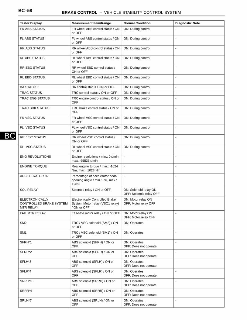
BC–58 BRAKE CONTROL – VEHICLE STABILITY CONTROL SYSTEM
BC
FR ABS STATUS FR wheel ABS control status / ON or OFF
ON: During control -
FL ABS STATUS FL wheel ABS control status / ON or OFF
ON: During control -
RR ABS STATUS RR wheel ABS control status / ON or OFF
ON: During control -
RL ABS STATUS RL wheel ABS control status / ON or OFF
ON: During control -
RR EBD STATUS RR wheel EBD control status / ON or OFF
ON: During control -
RL EBD STATUS RL wheel EBD control status / ON or OFF
ON: During control -
BA STATUS BA control status / ON or OFF ON: During control -
TRAC STATUS TRC control status / ON or OFF ON: During control -
TRAC ENG STATUS TRC engine control status / ON or OFF
ON: During control -
TRAC BRK STATUS TRC brake control status / ON or OFF
ON: During control -
FR VSC STATUS FR wheel VSC control status / ON or OFF
ON: During control -
FL VSC STATUS FL wheel VSC control status / ON or OFF
ON: During control -
RR VSC STATUS RR wheel VSC control status / ON or OFF
ON: During control -
RL VSC STATUS RL wheel VSC control status / ON or OFF
ON: During control -
ENG REVOLUTIONS Engine revolutions / min.: 0 r/min, max.: 65535 r/min
- -
ENGINE TORQUE Real engine torque / min.: -1024 Nm, max.: 1023 Nm
- -
ACCELERATOR % Percentage of accelerator pedal opening angle / min.: 0%, max.: 128%
- -
SOL RELAY Solenoid relay / ON or OFF ON: Solenoid relay ONOFF: Solenoid relay OFF
-
ELECTRONICALLY CONTROLLED BRAKE SYSTEM MTR RELAY
Electronically Controlled Brake System Motor relay (VSC1 relay) / ON or OFF
ON: Motor relay ONOFF: Motor relay OFF
-
FAIL MTR RELAY Fail-safe motor relay / ON or OFF ON: Motor relay ONOFF: Motor relay OFF
-
SM2 TRC / VSC solenoid (SM2) / ON or OFF
ON: Operates -
SM1 TRC / VSC solenoid (SM1) / ON or OFF
ON: Operates -
SFRH*1 ABS solenoid (SFRH) / ON or OFF
ON: OperatesOFF: Does not operate
-
SFRR*2 ABS solenoid (SFRR) / ON or OFF
ON: OperatesOFF: Does not operate
-
SFLH*3 ABS solenoid (SFLH) / ON or OFF
ON: OperatesOFF: Does not operate
-
SFLR*4 ABS solenoid (SFLR) / ON or OFF
ON: OperatesOFF: Does not operate
-
SRRH*5 ABS solenoid (SRRH) / ON or OFF
ON: OperatesOFF: Does not operate
-
SRRR*6 ABS solenoid (SRRR) / ON or OFF
ON: OperatesOFF: Does not operate
-
SRLH*7 ABS solenoid (SRLH) / ON or OFF
ON: OperatesOFF: Does not operate
-
Tester Display Measurement Item/Range Normal Condition Diagnostic Note

BRAKE CONTROL – VEHICLE STABILITY CONTROL SYSTEM BC–59
BC
HINT:• *1: SFRH (S: Solenoid, F: Front, R: Right, H:
Holding)• *2: SFRR (S: Solenoid, F: Front, R: Right, R:
Reduction)• *3: SFLH (S: Solenoid, F: Front, L: Left, H:
Holding)• *4: SFLR (S: Solenoid, F: Front, L: Left, R:
Reduction)• *5: SRRH (S: Solenoid, R: Rear, R: Right, H:
Holding)• *6: SRRR (S: Solenoid, R: Rear, R: Right, R:
Reduction)• *7: SRLH (S: Solenoid, R: Rear, L: Left, H:
Holding)• *8: SRLR (S: Solenoid, R: Rear, L: Left, R:
Reduction)• *9: w/ Downhill assist control• *10: for 2WD (w/ AUTO LSD)
SRLR*8 ABS solenoid (SRLR) / ON or OFF
ON: OperatesOFF: Does not operate
-
FR SPD OPN FR speed sensor open detection / ERROR or NORMAL
ERROR: Momentary interruptionNORMAL: Normal
-
FL SPD OPN FL speed sensor open detection / ERROR or NORMAL
ERROR: Momentary interruptionNORMAL: Normal
-
RR SPD OPN RR speed sensor open detection / ERROR or NORMAL
ERROR: Momentary interruptionNORMAL: Normal
-
RL SPD OPN RL speed sensor open detection / ERROR or NORMAL
ERROR: Momentary interruptionNORMAL: Normal
-
EFI COM OPN EFI communication open detection / ERROR or NORMAL
ERROR: Momentary interruptionNORMAL: Normal
-
YAW RATE OPN Yaw rate sensor open detection / ERROR or NORMAL
ERROR: Momentary interruptionNORMAL: Normal
-
DECELERAT OPN Deceleration sensor open detection / ERROR or NORMAL
ERROR: Momentary interruptionNORMAL: Normal
-
STEERING OPN Steering angle sensor open detection / ERROR or NORMAL
ERROR: Momentary interruptionNORMAL: Normal
-
M/C OPN Master cylinder pressure sensor open detection / ERROR or NORMAL
ERROR: Momentary interruptionNORMAL: Normal
-
#DTC Number of recorded DTCs/ min.: 0, max.: 255
Min.: 0Max.: 255
-
INSPECTION MODE Inspection mode / OTHER or INSPECT
- -
#IG ON2 Number of ignition switch ON operations after entering the inspection mode / min.: 0, max.: 255
- -
Tester Display Measurement Item/Range Normal Condition Diagnostic Note

BC–60 BRAKE CONTROL – VEHICLE STABILITY CONTROL SYSTEM
BC
2. PARFORM ACTIVE TESTHINT:Performing the intelligent tester's ACTIVE TEST allows relay, VSV, actuator and other items to be operated without removing any parts. Performing the ACTIVE TEST early in troubleshooting is one way to save time. The DATA LIST can be displayed during the ACTIVE TEST.(a) Connect the intelligent tester (with CAN VIM) to the
DLC3.(b) Turn the ignition switch ON.(c) Turn the intelligent tester on.(d) Perform the ACTIVE TEST according to the display
on the tester.HINT:• The ignition switch must be turned ON to
proceed to the ACTIVE TEST using the intelligent tester.
• The ACTIVE TESTs of the ABS solenoid, ABS motor relay, ABS warning light and BRAKE warning light are available when the vehicle is stopped.
• The motors stop automatically after 5 seconds of activation to prevent them from being damaged. When the motors are driven repeatedly, certain intervals are required.
• Each solenoid stops automatically after 2 seconds of activation to prevent them from being damaged, and can be operated again after a certain interval.
• Do not depress the brake pedal while only the pressure reduction solenoid valves are on.
• Do not drive 2 or more solenoids simultaneously except to operate the pressure holding solenoid valves and pressure reduction solenoid valves of each wheel.
Skid control ECUTester Display Test Part Control Range
ABS WARN LAMP Turns ABS warning light ON / OFF Observe combination meter
VSC WARN LAMP Turns VSC warning light ON / OFF Observe combination meter
BRAKE WARN LAMP Turns Brake warning light ON / OFF Observe combination meter
SLIP INDI LAMP Turns Slip indicator light ON / OFF Observe combination meter
D-HILL LIGHT*1 Turns downhill assist control indicator light ON / OFF
Observe combination meter
AUTO LSD LAMP*2 Turns AUTO LSD indicator light ON / OFF Observe combination meter
BUZZER Turns skid control buzzer ON / OFF Buzzer can be heard
STP LAMP RELAY Turns stop light relay (BRK relay) ON / OFF Operation sound of motor can be heard
SOL RELAY Turns ABS solenoid relay ON / OFF -
MOTOR RELAY Turns ABS motor relay ON / OFF Operation sound of motor can be heard
SRLR Turns ABS solenoid (SRLR) ON / OFF Operation sound of solenoid (clicking sound) can be heard
SRLH Turns ABS solenoid (SRLH) ON / OFF Operation sound of solenoid (clicking sound) can be heard
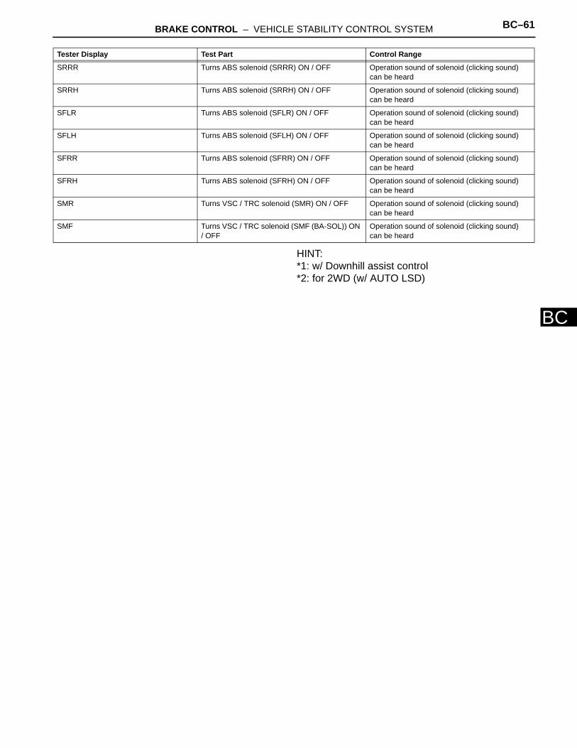
BRAKE CONTROL – VEHICLE STABILITY CONTROL SYSTEM BC–61
BC
HINT:*1: w/ Downhill assist control*2: for 2WD (w/ AUTO LSD)
SRRR Turns ABS solenoid (SRRR) ON / OFF Operation sound of solenoid (clicking sound) can be heard
SRRH Turns ABS solenoid (SRRH) ON / OFF Operation sound of solenoid (clicking sound) can be heard
SFLR Turns ABS solenoid (SFLR) ON / OFF Operation sound of solenoid (clicking sound) can be heard
SFLH Turns ABS solenoid (SFLH) ON / OFF Operation sound of solenoid (clicking sound) can be heard
SFRR Turns ABS solenoid (SFRR) ON / OFF Operation sound of solenoid (clicking sound) can be heard
SFRH Turns ABS solenoid (SFRH) ON / OFF Operation sound of solenoid (clicking sound) can be heard
SMR Turns VSC / TRC solenoid (SMR) ON / OFF Operation sound of solenoid (clicking sound) can be heard
SMF Turns VSC / TRC solenoid (SMF (BA-SOL)) ON / OFF
Operation sound of solenoid (clicking sound) can be heard
Tester Display Test Part Control Range

BC–62 BRAKE CONTROL – VEHICLE STABILITY CONTROL SYSTEM
BC
DIAGNOSTIC TROUBLE CODE CHARTHINT:• If no abnormality is found when inspecting parts, check the
skid control ECU and check for poor contact at the ground points.
• If a DTC is displayed during the DTC check, check the circuit for the DTC listed in the table below. For details of each DTC, refer to the page indicated.
• When 2 or more DTCs are detected, perform circuit inspections one by one until the problem is identified.
• All DTCs in the table below are detected in accordance with 1 trip detection logic.
DTC chart of ABSDTC No. Detection Item Trouble Area See page
C0200/31*1 Right Front Wheel Speed Sensor Signal
- Front speed sensor- Front speed sensor circuit- Sensor installation- Foreign matter on sensor rotor
BC-62
C0205/32*1 Left Front Wheel Speed Sensor Signal
- Front speed sensor- Front speed sensor circuit- Sensor installation- Foreign matter on sensor rotor
BC-62
C0210/33*1 Right Rear Wheel Speed Sensor Signal
- Skid control sensor RH (2WD)- Rear speed sensor RH (4WD)- Skid control sensor RH circuit (2WD)- Rear speed sensor RH circuit (4WD)- Sensor installation- Foreign matter on sensor rotor
BC-69
C0215/34*1 Left Rear Wheel Speed Sensor Signal
- Skid control sensor RH (2WD)- Rear speed sensor RH (4WD)- Skid control sensor RH circuit (2WD)- Rear speed sensor RH circuit (4WD)- Sensor installation- Foreign matter on sensor rotor
BC-69
C0226/21 SFR Solenoid Circuit - ABS and TRACTION actuator BC-76
C0236/22 SFL Solenoid Circuit - ABS and TRACTION actuator BC-76
C0246/23 SRR Solenoid Circuit - ABS and TRACTION actuator BC-76
C0256/24 SRL Solenoid Circuit - ABS and TRACTION actuator BC-76
C0273/13*1 Open in ABS Motor Relay Circuit - ABS1 H-fuse- VSC MTR relay- VSC MTR relay circuit- VSC FAIL relay- VSC FAIL relay circuit- ABS and TRACTION actuator
BC-78
C0274/14 Short to B+ in ABS Motor Relay Circuit
- ABS1 H-fuse- VSC MTR relay- VSC MTR relay circuit- VSC FAIL relay- VSC FAIL relay circuit- ABS and TRACTION actuator
BC-78
C0278/11 Open in ABS Solenoid Relay Circuit
- ABS2 H-fuse- Wire harness (+BS circuit)- ABS and TRACTION actuator
BC-83
C0279/12 Short to B+ in ABS Solenoid Relay Circuit
- ABS2 H-fuse- Wire harness (+BS circuit)- ABS and TRACTION actuator
BC-83
C1225/25 SM Solenoid Circuit - ABS and TRACTION actuator BC-76

BRAKE CONTROL – VEHICLE STABILITY CONTROL SYSTEM BC–63
BC
HINT:*1, *2
C1235/35 Foreign Object is Attached on Tip of Front Speed Sensor RH
- Front speed sensor- Front speed sensor circuit- Sensor installation
BC-62
C1236/36 Foreign Object is Attached on Tip of Front Speed Sensor LH
- Front speed sensor- Front speed sensor circuit- Sensor installation
BC-62
C1238/38 Foreign Object is Attached on Tip of Rear Speed Sensor RH
- Skid control sensor RH (2WD)- Rear speed sensor RH (4WD)- Skid control sensor RH circuit (2WD)- Rear speed sensor RH circuit (4WD)- Sensor installation
BC-69
C1239/39 Foreign Object is Attached on Tip of Rear Speed Sensor LH
- Skid control sensor RH (2WD)- Rear speed sensor RH (4WD)- Skid control sensor RH circuit (2WD)- Rear speed sensor RH circuit (4WD)- Sensor installation
BC-69
C1241/41 Low Battery Positive Voltage - Battery- Charging system- Power source circuit- Internal power supply circuit of skid control ECU
BC-99
C1243/43*1 Acceleration Sensor Stuck Malfunction
- Yaw rate sensor- Yaw rate sensor circuit
BC-96
C1244/44 Open or Short in Deceleration Sensor Circuit
- Yaw rate sensor- Yaw rate sensor circuit
BC-96
C1245/45*1 Acceleration Sensor Output Malfunction
- Yaw rate sensor- Yaw rate sensor circuit
BC-96
C1246/46*2 Master Cylinder Pressure Sensor Malfunction
- Master cylinder pressure sensor- Master cylinder pressure sensor circuit- Stop light switch circuit- ABS and TRACTION actuator
BC-103
C1249/49 Open in Stop Light Switch Circuit - STOP fuse- Stop light switch- Stop light switch circuit- ABS and TRACTION actuator- Stop light control relay
BC-105
C1251/51*1 Open in Pump Motor Circuit - Wire harness- ABS and TRACTION actuator
BC-109
C1267/67*3 Brake Pedal Load Sensing Switch
- Brake pedal load sensing switch- Brake pedal load sensing switch circuit
BC-111
C1337/37 Different Diameter Tire Malfunction
- Tire size BC-117
C1361/91 Short Circuit in ABS Motor Fail Safe Relay Circuit
- ABS1 H-fuse- VSC MTR relay- VSC MTR relay circuit- VSC FAIL relay- VSC FAIL relay circuit- ABS and TRACTION actuator
BC-78
C1381/97 Yaw Rate and / or Acceleration Sensor Power Supply Voltage Malfunction
- Yaw rate sensor- Yaw rate sensor circuit
BC-96
U0073/94 Control Module Communication Bus OFF
- CAN communication system BC-130
DTC No. Detection Item Trouble Area See page

BC–64 BRAKE CONTROL – VEHICLE STABILITY CONTROL SYSTEM
BC
Even after the trouble areas are repaired, the ABS warning light will not go off unless the following operations are performed.• *1:
(a)Drive the vehicle at 20 km/h (12 mph) for 30 seconds or more and check that the ABS warning light goes off.
(b)Clear the DTC(s).• *2:
(a)Keep the vehicle stationary for 5 seconds or more and depress the brake pedal lightly 2 or 3 times.
(b)Drive the vehicle at a vehicle speed of 50 km/h (31 mph) and keep depressing the brake pedal firmly for approximately 3 seconds.
(c)Repeat the above operation 3 times or more and check that the ABS warning light goes off.
(d)Clear the DTC(s).• *3: 16-inch disc
DTC chart of VSCDTC No. Detection Item Trouble Area See page
C1201/51 Engine Control System Malfunction
- Engine control system BC-85
C1203/53 ECM Communication Circuit Malfunction
- ECM BC-87
C1210/36 Zero Point Calibration of Yaw Rate Sensor Undone
- ABS and TRACTION actuator (skid control ECU)- Zero point calibration incomplete
BC-88
C1223/43 ABS Control System Malfunction - Skid control ECU BC-91
C1231/31 Steering Angle Sensor Circuit Malfunction
- Steering sensor- Steering sensor circuit- Steering sensor power supply- CAN communication system
BC-92
C1232/32 Stuck in Deceleration Sensor - Yaw rate sensor- Yaw rate sensor circuit
BC-96
C1234/34 Yaw Rate Sensor Malfunction - Yaw rate sensor- Yaw rate sensor circuit
BC-96
C1290/66 Steering Angle Sensor Zero Point Malfunction
- Yaw rate and deceleration sensor zero point calibration incomplete- Poor adjustment of centered position of steering wheel- Poor adjustment of front wheel alignment
BC-115
C1336/39 Zero Point Calibration of Acceleration Sensor Undone
- ABS and TRACTION actuator (skid control ECU)- Zero point calibration incomplete
BC-88
C1380/64 Stop Light Control Relay Malfunction
- Stop light assembly- Stop light switch circuit- STOP LP CTRL relay- ABS and TRACTION Actuator (skid control ECU)
BC-121
U0100/65 Lost Communication with ECM / PCM
- CAN communication system (Skid control ECU to ECM)
BC-130
U0123/62 Lost Communication with Yaw Rate Sensor Module
- CAN communication system (Skid control ECU to yaw rate and acceleration sensor)
BC-130
U0126/63 Lost Communication with Steering Angle Sensor Module
- CAN communication system BC-130

BRAKE CONTROL – VEHICLE STABILITY CONTROL SYSTEM BC–65
BC
DTC of ABS sensor check function
DTC of VSC sensor check function
DTC No. Detection Item Trouble Area See page
C1271/71 Low Output Signal of Front Speed Sensor RH (Test Mode DTC)
- Front speed sensor- Front speed sensor circuit- Sensor installation- Foreign matter on sensor rotor
BC-62
C1272/72 Low Output Signal of Front Speed Sensor LH (Test Mode DTC)
- Front speed sensor- Front speed sensor circuit- Sensor installation- Foreign matter on sensor rotor
BC-62
C1273/73 Low Output Signal of Rear Speed Sensor RH (Test Mode DTC)
- Skid control sensor RH (2WD)- Rear speed sensor RH (4WD)- Skid control sensor RH circuit (2WD)- Rear speed sensor RH circuit (4WD)- Sensor installation- Foreign matter on sensor rotor
BC-69
C1274/74 Low Output Signal of Rear Speed Sensor LH (Test Mode DTC)
- Skid control sensor RH (2WD)- Rear speed sensor RH (4WD)- Skid control sensor RH circuit (2WD)- Rear speed sensor RH circuit (4WD)- Sensor installation- Foreign matter on sensor rotor
BC-69
C1275/75 Abnormal Change in Output Signal of Front Speed Sensor RH (Test Mode DTC)
- Front speed sensor- Front speed sensor circuit- Sensor installation
BC-62
C1276/76 Abnormal Change in Output Signal of Front Speed Sensor LH (Test Mode DTC)
- Front speed sensor- Front speed sensor circuit- Sensor installation
BC-62
C1277/77 Abnormal Change in Output Signal of Rear Speed Sensor RH (Test Mode DTC)
- Skid control sensor RH (2WD)- Rear speed sensor RH (4WD)- Skid control sensor RH circuit (2WD)- Rear speed sensor RH circuit (4WD)- Sensor installation
BC-69
C1278/78 Abnormal Change in Output Signal of Rear Speed Sensor LH (Test Mode DTC)
- Skid control sensor RH (2WD)- Rear speed sensor RH (4WD)- Skid control sensor RH circuit (2WD)- Rear speed sensor RH circuit (4WD)- Sensor installation
BC-69
C1279/79 Deceleration Sensor Output Voltage Malfunction (Test Mode DTC)
- Yaw rate sensor- Yaw rate sensor circuit
BC-96
C1281/81 Master Cylinder Pressure Sensor Output Malfunction (Test Mode DTC)
- Master cylinder pressure sensor- Master cylinder pressure sensor circuit- Stop light switch circuit- ABS and TRACTION actuator
BC-103
U0124/95 Lost Communication with Lateral Acceleration Sensor Module
- CAN communication system (Skid control ECU to yaw rate and acceleration sensor)
BC-130
DTC No. Detection Item Trouble Area See page
C0371/71 Yaw Rate Sensor (Test Mode DTC)
- Yaw rate sensor- Yaw rate sensor circuit
BC-96
C1379/74* Downhill Assist Control Operation Switch (Test Mode DTC)
- Downhill assist control switch BC-119
BC–66 BRAKE CONTROL – VEHICLE STABILITY CONTROL SYSTEM
BC
HINT:*: w/ Downhill assist control

BRAKE CONTROL – VEHICLE STABILITY CONTROL SYSTEM BC–67
BC
DESCRIPTIONThe speed sensors detect the wheel speeds and send appropriate signals to the skid control ECU.Speed sensor rotors have rows of alternating N and S magnetic poles, and their magnetic fields change as the rotors turn.The speed sensors detect those magnetic changes and send pulse signals to the skid control ECU. The ECU monitors the wheel speeds through these pulse signals to control the ABS control system.DTCs C1271/71, C1272/72, C1275/75 and C1276/76 can be deleted when the speed sensor sends a vehicle speed signal or the test mode ends. DTCs C1271/71, C1272/72, C1275/75/75 and C1276/76 are output only in the test mode.
DTC C0200/31 Right Front Wheel Speed Sensor Signal
DTC C0205/32 Left Front Wheel Speed Sensor Signal
DTC C1235/35 Foreign Object is Attached on Tip of Front Speed Sensor RH
DTC C1236/36 Foreign Object is Attached on Tip of Front Speed Sensor LH
DTC C1271/71 Low Output Signal of Front Speed Sensor RH (Test Mode DTC)
DTC C1272/72 Low Output Signal of Front Speed Sensor LH (Test Mode DTC)
DTC C1275/75 Abnormal Change in Output Signal of Front Speed Sensor RH (Test Mode DTC)
DTC C1276/76 Abnormal Change in Output Signal of Front Speed Sensor LH (Test Mode DTC)
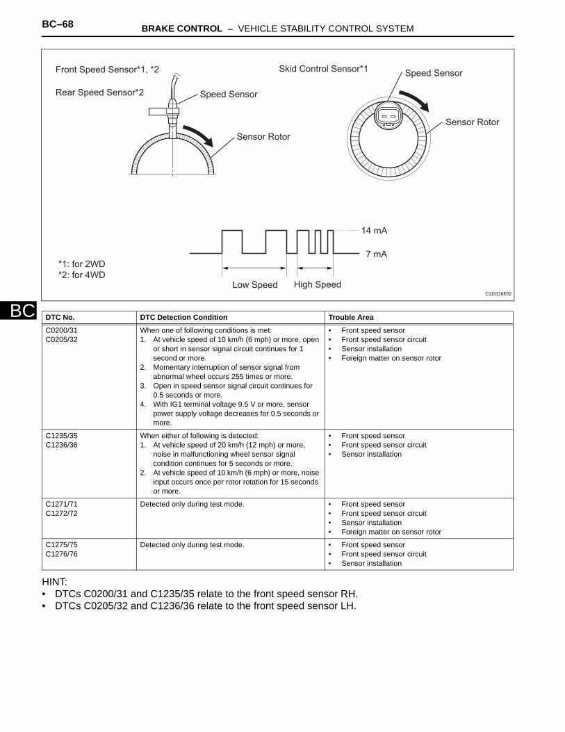
BC–68 BRAKE CONTROL – VEHICLE STABILITY CONTROL SYSTEM
BC
HINT:• DTCs C0200/31 and C1235/35 relate to the front speed sensor RH.• DTCs C0205/32 and C1236/36 relate to the front speed sensor LH.
DTC No. DTC Detection Condition Trouble Area
C0200/31C0205/32
When one of following conditions is met:1. At vehicle speed of 10 km/h (6 mph) or more, open
or short in sensor signal circuit continues for 1 second or more.
2. Momentary interruption of sensor signal from abnormal wheel occurs 255 times or more.
3. Open in speed sensor signal circuit continues for 0.5 seconds or more.
4. With IG1 terminal voltage 9.5 V or more, sensor power supply voltage decreases for 0.5 seconds or more.
• Front speed sensor• Front speed sensor circuit• Sensor installation• Foreign matter on sensor rotor
C1235/35C1236/36
When either of following is detected:1. At vehicle speed of 20 km/h (12 mph) or more,
noise in malfunctioning wheel sensor signal condition continues for 5 seconds or more.
2. At vehicle speed of 10 km/h (6 mph) or more, noise input occurs once per rotor rotation for 15 seconds or more.
• Front speed sensor• Front speed sensor circuit• Sensor installation
C1271/71C1272/72
Detected only during test mode. • Front speed sensor• Front speed sensor circuit• Sensor installation• Foreign matter on sensor rotor
C1275/75C1276/76
Detected only during test mode. • Front speed sensor• Front speed sensor circuit• Sensor installation
Front Speed Sensor*1, *2
Rear Speed Sensor*2
Skid Control Sensor*1
Speed Sensor
Speed Sensor
Sensor Rotor
Sensor Rotor
Low Speed High Speed
14 mA
7 mA*1: for 2WD
*2: for 4WD
C115116E02
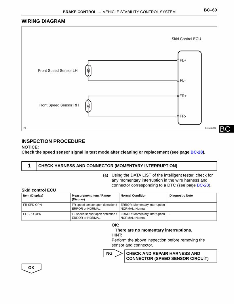
BRAKE CONTROL – VEHICLE STABILITY CONTROL SYSTEM BC–69
BC
WIRING DIAGRAM
INSPECTION PROCEDURENOTICE:Check the speed sensor signal in test mode after cleaning or replacement (see page BC-28).
(a) Using the DATA LIST of the intelligent tester, check for any momentary interruption in the wire harness and connector corresponding to a DTC (see page BC-23).
Skid control ECU
OK:There are no momentary interruptions.
HINT:Perform the above inspection before removing the sensor and connector.
NG
OK
1 CHECK HARNESS AND CONNECTOR (MOMENTARY INTERRUPTION)
Skid Control ECU
Front Speed Sensor LH
Front Speed Sensor RH
FL+
FL-
FR+
FR-
C136041E01
Item (Display) Measurement Item / Range (Display)
Normal Condition Diagnostic Note
FR SPD OPN FR speed sensor open detection / ERROR or NORMAL
ERROR: Momentary interruptionNORMAL: Normal
-
FL SPD OPN FL speed sensor open detection / ERROR or NORMAL
ERROR: Momentary interruptionNORMAL: Normal
-
CHECK AND REPAIR HARNESS AND CONNECTOR (SPEED SENSOR CIRCUIT)

BC–70 BRAKE CONTROL – VEHICLE STABILITY CONTROL SYSTEM
BC
(a) Check the DATA LIST for proper functioning of the front speed sensor.
Skid control ECU
OK:There is almost no difference between actual wheel speed and displayed speed value.
HINT:There is a tolerance of +-10% in the speedometer indication.
NG
OK
(a) Perform a TEST MODE inspection and check for DTCs (see page BC-28).OK:
No DTC output.
NG
OK
(a) Clear the DTC(s) (see page BC-47).(b) Start the engine.(c) Drive the vehicle at a speed of 20 km/h (12 mph) or more
for at least 60 seconds.(d) Check if the same DTC(s) is output (see page BC-47).
Result
B
A
2 READ VALUE OF DATA LIST (FRONT SPEED SENSOR)
Item (Display) Measurement Item / Range (Display) Normal Condition
FR WHEEL SPD Wheel speed sensor (FR) reading / min.: 0 km/h (0 mph), max.: 326 km/h (202.8 mph)
Similar to speed indicated on speedometer
FL WHEEL SPD Wheel speed sensor (FL) reading / min.: 0 km/h (0 mph), max.: 326 km/h (202.8 mph)
Similar to speed indicated on speedometer
Go to step 5
3 PERFORM TEST MODE INSPECTION (SIGNAL CHECK)
CHECK AND REPAIR HARNESS AND CONNECTOR (SPEED SENSOR CIRCUIT)
4 RECONFIRM DTC
Result Proceed to
DTC is not output A
DTC is output B
Go to step 10
END
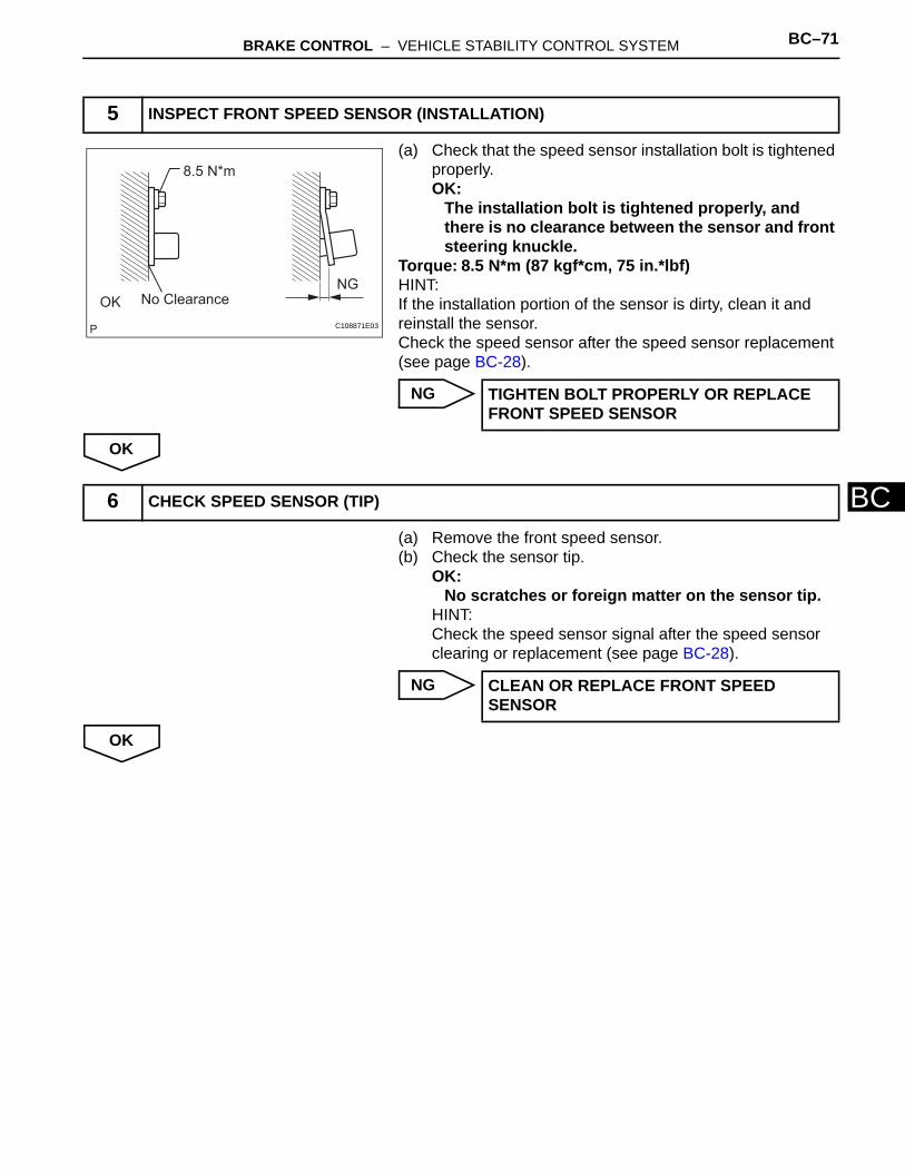
BRAKE CONTROL – VEHICLE STABILITY CONTROL SYSTEM BC–71
BC
(a) Check that the speed sensor installation bolt is tightened properly.OK:
The installation bolt is tightened properly, and there is no clearance between the sensor and front steering knuckle.
Torque: 8.5 N*m (87 kgf*cm, 75 in.*lbf)HINT:If the installation portion of the sensor is dirty, clean it and reinstall the sensor.Check the speed sensor after the speed sensor replacement (see page BC-28).
NG
OK
(a) Remove the front speed sensor.(b) Check the sensor tip.
OK:No scratches or foreign matter on the sensor tip.
HINT:Check the speed sensor signal after the speed sensor clearing or replacement (see page BC-28).
NG
OK
5 INSPECT FRONT SPEED SENSOR (INSTALLATION)
No Clearance
8.5 N*m
OK
NG
C108871E03
TIGHTEN BOLT PROPERLY OR REPLACE FRONT SPEED SENSOR
6 CHECK SPEED SENSOR (TIP)
CLEAN OR REPLACE FRONT SPEED SENSOR
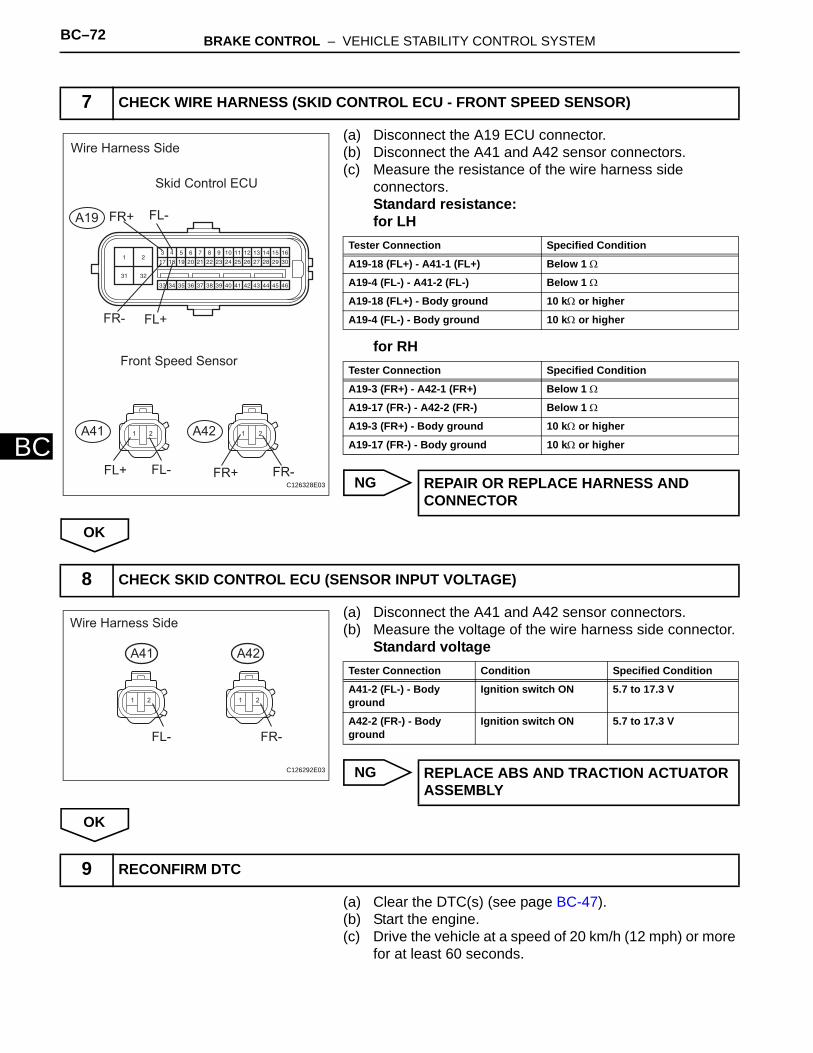
BC–72 BRAKE CONTROL – VEHICLE STABILITY CONTROL SYSTEM
BC
(a) Disconnect the A19 ECU connector.(b) Disconnect the A41 and A42 sensor connectors.(c) Measure the resistance of the wire harness side
connectors.Standard resistance:for LH
for RH
NG
OK
(a) Disconnect the A41 and A42 sensor connectors.(b) Measure the voltage of the wire harness side connector.
Standard voltage
NG
OK
(a) Clear the DTC(s) (see page BC-47).(b) Start the engine.(c) Drive the vehicle at a speed of 20 km/h (12 mph) or more
for at least 60 seconds.
7 CHECK WIRE HARNESS (SKID CONTROL ECU - FRONT SPEED SENSOR)
1 2 1 2
Wire Harness Side
Skid Control ECU
Front Speed Sensor
A19
A41 A42
FL-
FL+FR-
FR+
FL+ FL- FR+ FR-C126328E03
Tester Connection Specified Condition
A19-18 (FL+) - A41-1 (FL+) Below 1 Ω
A19-4 (FL-) - A41-2 (FL-) Below 1 Ω
A19-18 (FL+) - Body ground 10 kΩ or higher
A19-4 (FL-) - Body ground 10 kΩ or higher
Tester Connection Specified Condition
A19-3 (FR+) - A42-1 (FR+) Below 1 Ω
A19-17 (FR-) - A42-2 (FR-) Below 1 Ω
A19-3 (FR+) - Body ground 10 kΩ or higher
A19-17 (FR-) - Body ground 10 kΩ or higher
REPAIR OR REPLACE HARNESS AND CONNECTOR
8 CHECK SKID CONTROL ECU (SENSOR INPUT VOLTAGE)
1 2 1 2
Wire Harness Side
A41 A42
FL- FR-
C126292E03
Tester Connection Condition Specified Condition
A41-2 (FL-) - Body ground
Ignition switch ON 5.7 to 17.3 V
A42-2 (FR-) - Body ground
Ignition switch ON 5.7 to 17.3 V
REPLACE ABS AND TRACTION ACTUATOR ASSEMBLY
9 RECONFIRM DTC
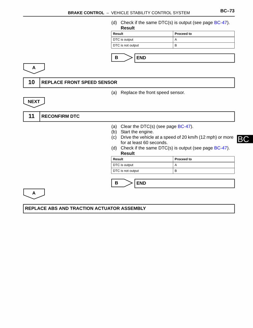
BRAKE CONTROL – VEHICLE STABILITY CONTROL SYSTEM BC–73
BC
(d) Check if the same DTC(s) is output (see page BC-47).Result
B
A
(a) Replace the front speed sensor.
NEXT
(a) Clear the DTC(s) (see page BC-47).(b) Start the engine.(c) Drive the vehicle at a speed of 20 km/h (12 mph) or more
for at least 60 seconds.(d) Check if the same DTC(s) is output (see page BC-47).
Result
B
A
Result Proceed to
DTC is output A
DTC is not output B
END
10 REPLACE FRONT SPEED SENSOR
11 RECONFIRM DTC
Result Proceed to
DTC is output A
DTC is not output B
END
REPLACE ABS AND TRACTION ACTUATOR ASSEMBLY

BC–74 BRAKE CONTROL – VEHICLE STABILITY CONTROL SYSTEM
BC
DESCRIPTIONRefer to DTC C0200/31 (see page BC-62).DTCs C1273/73, C1274/74, C1277/77 and C1278/78 can be deleted when the speed sensor sends a vehicle speed signal or the test mode ends. DTCs C1273/73, C1274/74, C1277/77 and C1278/78 are output only in the test mode.
DTC C0210/33 Right Rear Wheel Speed Sensor Signal
DTC C0215/34 Left Rear Wheel Speed Sensor Signal
DTC C1238/38 Foreign Object is Attached on Tip of Rear Speed Sensor RH
DTC C1239/39 Foreign Object is Attached on Tip of Rear Speed Sensor LH
DTC C1273/73 Low Output Signal of Rear Speed Sensor RH (Test Mode DTC)
DTC C1274/74 Low Output Signal of Rear Speed Sensor LH (Test Mode DTC)
DTC C1277/77 Abnormal Change in Output Signal of Rear Speed Sensor RH (Test Mode DTC)
DTC C1278/78 Abnormal Change in Output Signal of Rear Speed Sensor LH (Test Mode DTC)
DTC No. DTC Detection Condition Trouble Area
C0210/33C0215/34
When one of following conditions is met:1. At vehicle speed of 10 km/h (6 mph) or more, open
or short in sensor signal circuit continues for 1 second or more.
2. Momentary interruption of sensor signal from abnormal wheel occurs 255 times or more.
3. Open in speed sensor signal circuit continues for 0.5 seconds or more.
4. With IG1 terminal voltage 9.5 V or more, sensor power supply voltage decreases for 0.5 seconds or more.
• Skid control sensor (for 2WD)• Rear speed sensor (for 4WD)• Skid control sensor circuit (for 2WD)• Rear speed sensor circuit (4WD)• Sensor installation• Foreign matter on sensor rotor
C1238/38C1239/39
When either condition below is met:1. At vehicle speed of 20 km/h (12 mph) or more,
noise in malfunctioning wheel sensor signal condition continues for 5 seconds or more.
2. At vehicle speed of 10 km/h (6 mph) or more, noise input occurs once per rotor rotation for 15 seconds or more.
• Skid control sensor (for 2WD)• Rear speed sensor (for 4WD)• Skid control sensor circuit (for 2WD)• Rear speed sensor circuit (for 4WD)• Sensor installation
C1273/73C1274/74
Detected only during test mode. • Skid control sensor (for 2WD)• Rear speed sensor (for 4WD)• skid control sensor circuit (for 2WD)• Rear speed sensor circuit (for 4WD)• Sensor installation• Foreign matter on sensor rotor
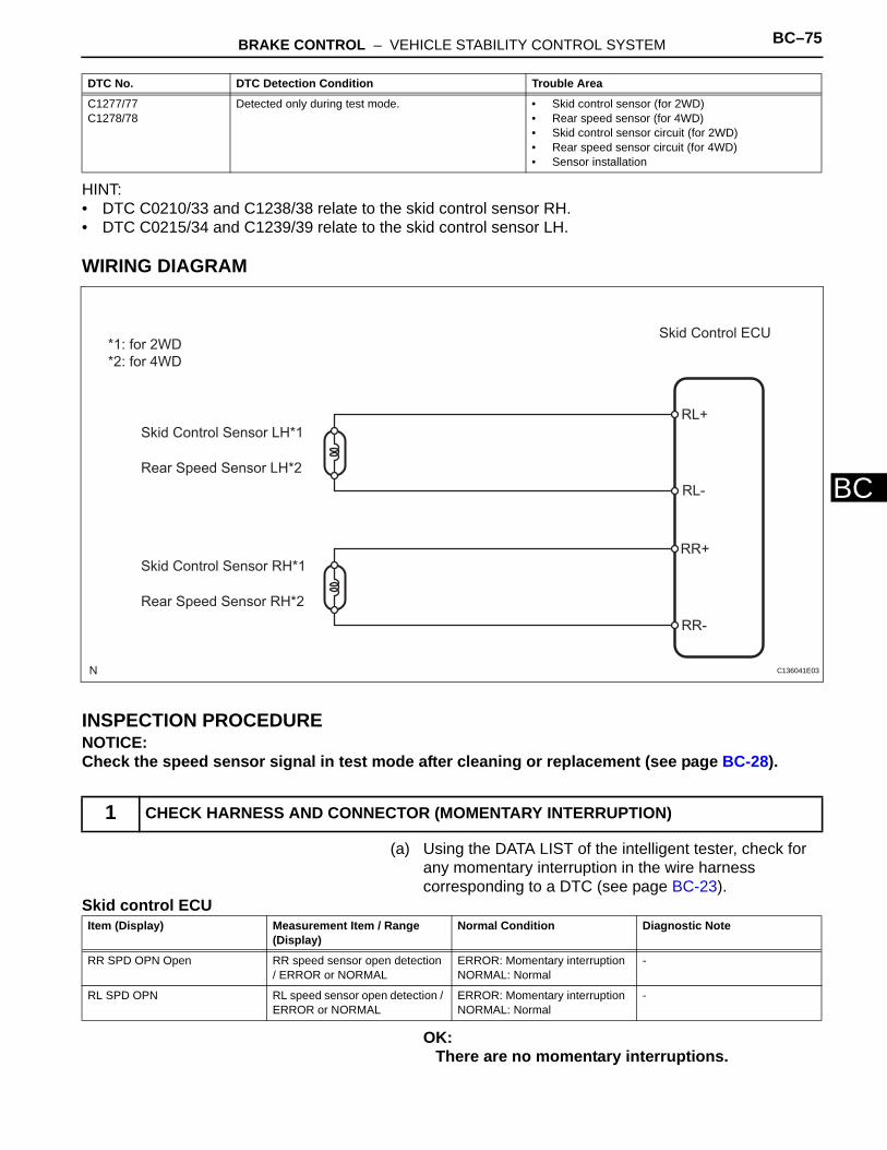
BRAKE CONTROL – VEHICLE STABILITY CONTROL SYSTEM BC–75
BC
HINT:• DTC C0210/33 and C1238/38 relate to the skid control sensor RH.• DTC C0215/34 and C1239/39 relate to the skid control sensor LH.
WIRING DIAGRAM
INSPECTION PROCEDURENOTICE:Check the speed sensor signal in test mode after cleaning or replacement (see page BC-28).
(a) Using the DATA LIST of the intelligent tester, check for any momentary interruption in the wire harness corresponding to a DTC (see page BC-23).
Skid control ECU
OK:There are no momentary interruptions.
C1277/77C1278/78
Detected only during test mode. • Skid control sensor (for 2WD)• Rear speed sensor (for 4WD)• Skid control sensor circuit (for 2WD)• Rear speed sensor circuit (for 4WD)• Sensor installation
1 CHECK HARNESS AND CONNECTOR (MOMENTARY INTERRUPTION)
DTC No. DTC Detection Condition Trouble Area
Skid Control ECU
Skid Control Sensor LH*1
Skid Control Sensor RH*1
Rear Speed Sensor LH*2
Rear Speed Sensor RH*2
*1: for 2WD
*2: for 4WD
RL+
RL-
RR+
RR-
C136041E03
Item (Display) Measurement Item / Range (Display)
Normal Condition Diagnostic Note
RR SPD OPN Open RR speed sensor open detection / ERROR or NORMAL
ERROR: Momentary interruptionNORMAL: Normal
-
RL SPD OPN RL speed sensor open detection / ERROR or NORMAL
ERROR: Momentary interruptionNORMAL: Normal
-
BC–76 BRAKE CONTROL – VEHICLE STABILITY CONTROL SYSTEM
BC
HINT:Perform this inspection before removing the sensor and connector.
NG
OK
(a) Check the DATA LIST for proper functioning of the rear speed sensor.
Skid control ECU
OK:There is almost no difference between actual wheel speed and displayed speed value.
HINT:There is a tolerance of +-10% in the speedometer indication.
NG
OK
(a) Perform a TEST MODE inspection and check for DTCs (see page BC-28).OK:
No DTCs output.
NG
OK
(a) Clear the DTC(s) (see page BC-47).(b) Start the engine.(c) Drive the vehicle at a speed of 20 km/h (12 mph) or more
for at least 60 seconds.
REPAIR OR REPLACE HARNESS AND CONNECTOR
2 READ VALUE OF INTELLIGENT TESTER (REAR SPEED SENSOR)
Item (Display) Measurement Item / Range (Display)
Normal Condition Diagnostic Note
RR WHEEL SPD Wheel speed sensor (RR) reading : min.: 0 km/h (0 mph), max.: 326 km/h (202.8 mph)
Similar to speed indicated on speedometer
-
RL WHEEL SPD Wheel speed sensor (RL) reading : min.: 0 km/h (0 mph), max.: 326 km/h (202.8 mph)
Similar to speed indicated on speedometer
-
Go to step 5
3 PERFORM TEST MODE INSPECTION (SIGNAL CHECK)
REPAIR OR REPLACE HARNESS AND CONNECTOR
4 RECONFIRM DTC
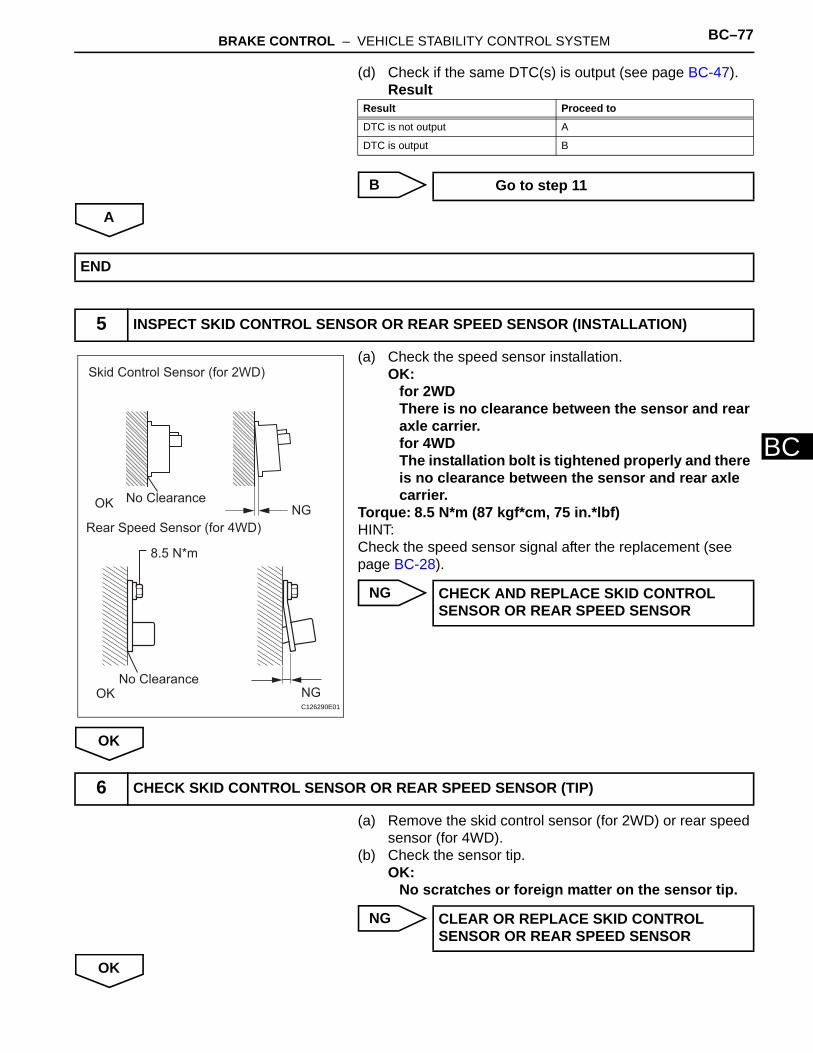
BRAKE CONTROL – VEHICLE STABILITY CONTROL SYSTEM BC–77
BC
(d) Check if the same DTC(s) is output (see page BC-47).Result
B
A
(a) Check the speed sensor installation.OK:
for 2WDThere is no clearance between the sensor and rear axle carrier.for 4WDThe installation bolt is tightened properly and there is no clearance between the sensor and rear axle carrier.
Torque: 8.5 N*m (87 kgf*cm, 75 in.*lbf)HINT:Check the speed sensor signal after the replacement (see page BC-28).
NG
OK
(a) Remove the skid control sensor (for 2WD) or rear speed sensor (for 4WD).
(b) Check the sensor tip.OK:
No scratches or foreign matter on the sensor tip.
NG
OK
Result Proceed to
DTC is not output A
DTC is output B
Go to step 11
END
5 INSPECT SKID CONTROL SENSOR OR REAR SPEED SENSOR (INSTALLATION)
Skid Control Sensor (for 2WD)
Rear Speed Sensor (for 4WD)
No Clearance
No Clearance
8.5 N*m
NGOK
OK NGC126290E01
CHECK AND REPLACE SKID CONTROL SENSOR OR REAR SPEED SENSOR
6 CHECK SKID CONTROL SENSOR OR REAR SPEED SENSOR (TIP)
CLEAR OR REPLACE SKID CONTROL SENSOR OR REAR SPEED SENSOR

BC–78 BRAKE CONTROL – VEHICLE STABILITY CONTROL SYSTEM
BC
(a) Disconnect the A19 ECU connector.(b) Disconnect W1 and V1 sensor connectors for 2WD.
Disconnect K23 and K22 sensor connectors for 4WD.(c) Measure the resistance of the wire harness side
connectors.Standard resistance:for 2WD (LH Side)
for 2WD (RH Side)
for 4WD (LH Side)
for 4WD (RH Side)
NG
OK
7 CHECK WIRE HARNESS (SKID CONTROL ECU - REAR SPEED SENSOR)
21 21
Wire Harness Side
Skid Control ECU
A19RR+ RL-
RR- RL+
Skid Control Sensor (2WD)
W1 V1
RL+ RL- RR+ RR-
Rear Speed Sensor (4WD)
K23 K22
RL+ RL- RR+ RR-
C135700E01
Tester Connection Specified Condition
A19-20 (RL+) - W1-1 (RL+) Below 1 Ω
A19-6 (RL-) - W1-2 (RL-) Below 1 Ω
A19-20 (RL+) - Body ground 10 kΩ or higher
A19-6 (RL-) - Body ground 10 kΩ or higher
Tester Connection Specified Condition
A19-5 (RR+) - V1-1 (RR+) Below 1 Ω
A19-19 (RR-) - V1-2 (RR-) Below 1 Ω
A19-5 (RR+) - Body ground 10 kΩ or higher
A19-19 (RR-) - Body ground 10 kΩ or higher
Tester Connection Specified Condition
A19-20 (RL+) - K23-1 (RL+) Below 1 Ω
A19-6 (RL-) - K23-2 (RL-) Below 1 Ω
A19-20 (RL+) - Body ground 10 kΩ or higher
A19-6 (RL-) - Body ground 10 kΩ or higher
Tester Connection Specified Condition
A19-5 (RR+) - K22-1 (RR+) Below 1 Ω
A19-19 (RR-) - K22-2 (RR-) Below 1 Ω
A19-5 (RR+) - Body ground 10 kΩ or higher
A19-19 (RR-) - Body ground 10 kΩ or higher
REPAIR OR REPLACE HARNESS AND CONNECTOR

BRAKE CONTROL – VEHICLE STABILITY CONTROL SYSTEM BC–79
BC
(a) Disconnect the W1 and V1 sensor connectors for 2WD.Disconnect the K23 and K22 sensor connectors for 4WD.
(b) Measure the voltage of the wire harness side connectors.Standard voltage:for 2WD
for 4WD
NG
OK
(a) Clear the DTC(s) (see page BC-47).(b) Start the engine.(c) Drive the vehicle at a speed of 20 km/h (12 mph) or more
for at least 60 seconds.(d) Check if the same DTC(s) is output (see page BC-47).
Result
B
A
(a) Replace the skid control sensor (2WD) or rear speed sensor (4WD).
NEXT
8 CHECK SKID CONTROL ECU (SENSOR INPUT VOLTAGE)
21 21
Wire Harness Side
Skid Control Sensor (2WD)
W1 V1
RL+ RL- RR+ RR-
Rear Speed Sensor (4WD)
K23 K22
RL+ RL- RR+ RR-
C135699E01
Tester Connection Condition Specified Condition
W1-1 (RL+) - Body ground
Ignition switch ON 5.7 to 17.3 V
V1-1 (RR+) - Body ground
Ignition switch ON 5.7 to 17.3 V
Tester Connection Condition Specified Condition
K23-1 (RL+) - Body ground
Ignition switch ON 5.7 to 17.3 V
K22-1 (RR+) - Body ground
Ignition switch ON 5.7 to 17.3 V
REPLACE ABS AND TRACTION ACTUATOR ASSEMBLY
9 RECONFIRM DTC
Result Proceed to
DTC is output A
DTC is not output B
END
10 REPLACE SKID CONTROL SENSOR OR REAR SPEED SENSOR

BC–80 BRAKE CONTROL – VEHICLE STABILITY CONTROL SYSTEM
BC
(a) Clear the DTC(s) (see page BC-47).(b) Start the engine.(c) Drive the vehicle at a speed of 20 km/h (12 mph) or more
for at least 60 seconds.(d) Check if the same DTC(s) is output (see page BC-47).
Result
B
A
11 RECONFIRM DTC
Result Proceed to
DTC is output A
DTC is not output B
END
REPLACE ABS AND TRACTION ACTUATOR ASSEMBLY
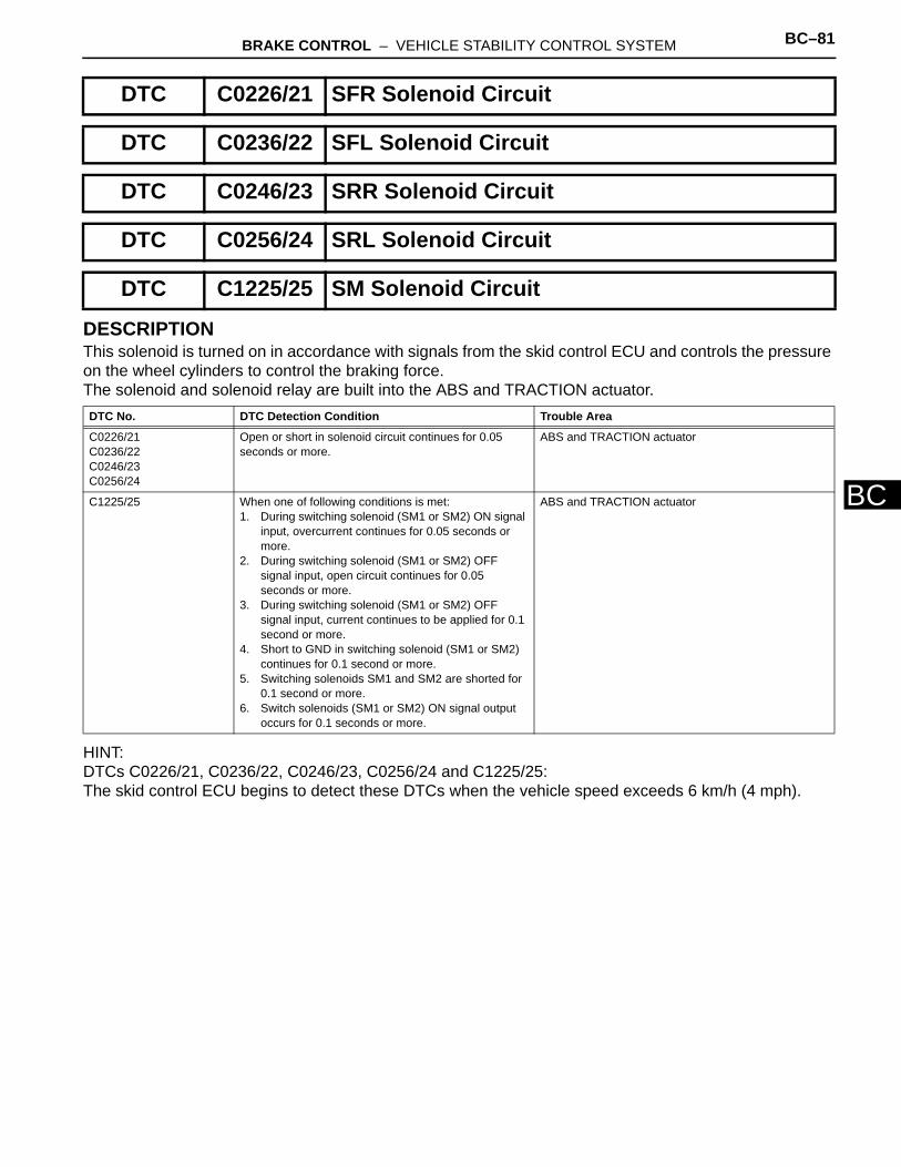
BRAKE CONTROL – VEHICLE STABILITY CONTROL SYSTEM BC–81
BC
DESCRIPTIONThis solenoid is turned on in accordance with signals from the skid control ECU and controls the pressure on the wheel cylinders to control the braking force.The solenoid and solenoid relay are built into the ABS and TRACTION actuator.
HINT:DTCs C0226/21, C0236/22, C0246/23, C0256/24 and C1225/25:The skid control ECU begins to detect these DTCs when the vehicle speed exceeds 6 km/h (4 mph).
DTC C0226/21 SFR Solenoid Circuit
DTC C0236/22 SFL Solenoid Circuit
DTC C0246/23 SRR Solenoid Circuit
DTC C0256/24 SRL Solenoid Circuit
DTC C1225/25 SM Solenoid Circuit
DTC No. DTC Detection Condition Trouble Area
C0226/21C0236/22C0246/23C0256/24
Open or short in solenoid circuit continues for 0.05 seconds or more.
ABS and TRACTION actuator
C1225/25 When one of following conditions is met:1. During switching solenoid (SM1 or SM2) ON signal
input, overcurrent continues for 0.05 seconds or more.
2. During switching solenoid (SM1 or SM2) OFF signal input, open circuit continues for 0.05 seconds or more.
3. During switching solenoid (SM1 or SM2) OFF signal input, current continues to be applied for 0.1 second or more.
4. Short to GND in switching solenoid (SM1 or SM2) continues for 0.1 second or more.
5. Switching solenoids SM1 and SM2 are shorted for 0.1 second or more.
6. Switch solenoids (SM1 or SM2) ON signal output occurs for 0.1 seconds or more.
ABS and TRACTION actuator

BC–82 BRAKE CONTROL – VEHICLE STABILITY CONTROL SYSTEM
BC
WIRING DIAGRAM
INSPECTION PROCEDURE
(a) Clear the DTC(s) (see page BC-47).(b) Start the engine.(c) Drive the vehicle at 6 km/h (4 mph) or more to activate
the initial check.(d) Check if the same DTC(s) is output (see page BC-47).
Result
HINT:The DTCs may be stored due to a malfunction in the connector terminal.
B
A
1 RECONFIRM DTC
Skid Control ECU
ABS and TRACTION Actuator
C126325E01
Result Proceed to
DTC is output A
DTC is not output B
END
REPLACE ABS AND TRACTION ACTUATOR

BRAKE CONTROL – VEHICLE STABILITY CONTROL SYSTEM BC–83
BC
DESCRIPTIONIf a DTC related to the motor line is stored, the VSC FAIL (fail-safe) relay cuts off the power supply to the VSC MTR relay and performs the fail-safe operation.While the ABS, TRC, VSC, or BA is operating, the skid control ECU turns the VSC FAIL relay on and activates the pump motor in the ABS and TRACTION actuator.These DTCs may be stored if the motor relay (+BM) voltage becomes lower than the DTC detecting condition due to insufficient output from the battery or alternator.
HINT:DTCs C0273/13, C0274/14 and C1361/91: The skid control ECU begins to detect these DTCs when the vehicle speed exceeds 6 km/h (4 mph).
DTC C0273/13 Open in ABS Motor Relay Circuit
DTC C0274/14 Short to B+ in ABS Motor Relay Circuit
DTC C1361/91 Short Circuit in ABS Motor Fail Safe Relay Cir-cuit
DTC No. DTC Detection Condition Trouble Area
C0273/13 When either condition below is met:1. All of following conditions continue for 0.12 seconds
or more.(a) IG1 terminal voltage between 9.5 V and 17.2 V.(b) During initial check or ABS/TRC/VSC/BA.(c) Relay contact open when relay on.
2. Both of following conditions continue for 0.12 seconds or more.(a) IG1 terminal voltage 9.5 V or less.(b) Relay contact remains open when relay on.
• ABS1 H-fuse• VSC MTR relay• VSC MTR relay circuit• VSC FAIL relay• VSC FAIL relay circuit• ABS and TRACTION actuator
C0274/14 Despite motor relay (VSC MTR relay) off, motor relay remains closed for 4 seconds or more.
• ABS1 H-fuse• VSC MTR relay• VSC MTR relay circuit• VSC FAIL relay• VSC FAIL relay circuit• ABS and TRACTION actuator
C1361/91 Immediately after ignition switch ON, motor fail-safe relay (VSC FAIL relay) contact closed for 4 seconds when motor fail-safe relay (VSC FAIL relay) off.
• ABS1 H-fuse• VSC MTR relay• VSC MTR relay circuit• VSC FAIL relay• VSC FAIL relay circuit• ABS and TRACTION actuator
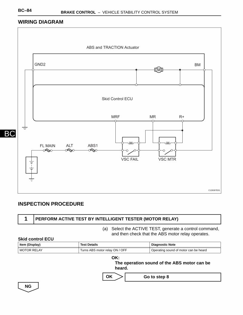
BC–84 BRAKE CONTROL – VEHICLE STABILITY CONTROL SYSTEM
BC
WIRING DIAGRAM
INSPECTION PROCEDURE
(a) Select the ACTIVE TEST, generate a control command, and then check that the ABS motor relay operates.
Skid control ECU
OK:The operation sound of the ABS motor can be heard.
OK
NG
1 PERFORM ACTIVE TEST BY INTELLIGENT TESTER (MOTOR RELAY)
M
Skid Control ECU
GND2 BM
R+MRMRF
VSC MTRVSC FAIL
ABS1ALTFL MAIN
ABS and TRACTION Actuator
C126307E01
Item (Display) Test Details Diagnostic Note
MOTOR RELAY Turns ABS motor relay ON / OFF Operating sound of motor can be heard
Go to step 8
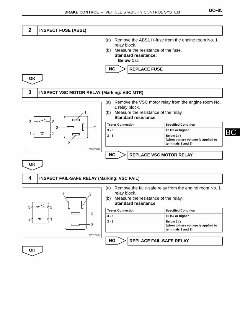
BRAKE CONTROL – VEHICLE STABILITY CONTROL SYSTEM BC–85
BC
(a) Remove the ABS1 H-fuse from the engine room No. 1 relay block.
(b) Measure the resistance of the fuse.Standard resistance:
Below 1 Ω
NG
OK
(a) Remove the VSC motor relay from the engine room No. 1 relay block.
(b) Measure the resistance of the relay.Standard resistance
NG
OK
(a) Remove the faile-safe relay from the engine room No. 1 relay block.
(b) Measure the resistance of the relay.Standard resistance
NG
OK
2 INSPECT FUSE (ABS1)
REPLACE FUSE
3 INSPECT VSC MOTOR RELAY (Marking: VSC MTR)
21
A092673E05
Tester Connection Specified Condition
3 - 5 10 kΩ or higher
3 - 5 Below 1 Ω(when battery voltage is applied to terminals 1 and 2)
REPLACE VSC MOTOR RELAY
4 INSPECT FAIL-SAFE RELAY (Marking: VSC FAIL)
1
1
2
2
3
3
5
5
B060778E62
Tester Connection Specified Condition
3 - 5 10 kΩ or higher
3 - 5 Below 1 Ω(when battery voltage is applied to terminals 1 and 2)
REPLACE FAIL-SAFE RELAY

BC–86 BRAKE CONTROL – VEHICLE STABILITY CONTROL SYSTEM
BC
(a) Remove the fail-safe relay from the engine room No. 1 relay block.
(b) Measure the voltage of the wire harness side connector.Standard voltage
NG
OK
(a) Remove the fail-safe and VSC motor relays from the engine room No. 1 relay block.
(b) Measure the resistance of the relay terminals.Standard resistance
NG
OK
5 CHECK WIRE HARNESS (FAIL-SAFE RELAY - BATTERY)
1
53
2
Wire Harness Side
Fail-safe Relay
C126326E01
Tester Connection Specified Condition
VSC FAIL relay terminal 5 - Body ground
10 to 14 V
REPAIR OR REPLACE HARNESS AND CONNECTOR
6 CHECK ENGINE ROOM NO. 1 RELAY BLOCK (FAIL-SAFE RELAY - VSC MOTOR RELAY AND BODY GROUND)
1
53
2
Wire Haness Side
VSC Motor Relay
Fail-safe
Relay
C126304E01
Tester Connection Specified Condition
VSC FAIL relay terminal 3 - VSC MTR relay terminal 5
Below 1 Ω
VSC FAIL relay terminal 3 - Body ground
10 kΩ or higher
REPLACE ENGINE ROOM NO. 1 RELAY BLOCK
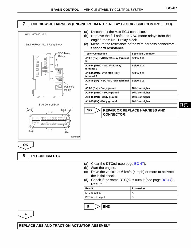
BRAKE CONTROL – VEHICLE STABILITY CONTROL SYSTEM BC–87
BC
(a) Disconnect the A19 ECU connector.(b) Remove the fail-safe and VSC motor relays from the
engine room No. 1 relay block.(c) Measure the resistance of the wire harness connectors.
Standard resistance
NG
OK
(a) Clear the DTC(s) (see page BC-47).(b) Start the engine.(c) Drive the vehicle at 6 km/h (4 mph) or more to activate
the initial check.(d) Check if the same DTC(s) is output (see page BC-47).
Result
B
A
7 CHECK WIRE HARNESS (ENGINE ROOM NO. 1 RELAY BLOCK - SKID CONTROL ECU)
1
53
2
Wire Harness Side
Engine Room No. 1 Relay Block
Skid Control ECU
BM
MRF MR
R+
A19
VSC Motor
Relay
Fail-safe
Relay
C126327E04
Tester Connection Specified Condition
A19-2 (BM) - VSC MTR relay terminal 3
Below 1 Ω
A19-14 (MRF) - VSC FAIL relay terminal 2
Below 1 Ω
A19-15 (MR) - VSC MTR relay terminal 2
Below 1 Ω
A19-45 (R+) - VSC FAIL relay terminal 1
Below 1 Ω
A19-2 (BM) - Body ground 10 kΩ or higher
A19-14 (MRF) - Body ground 10 kΩ or higher
A19-15 (MR) - Body ground 10 kΩ or higher
A19-45 (R+) - Body ground 10 kΩ or higher
REPAIR OR REPLACE HARNESS AND CONNECTOR
8 RECONFIRM DTC
Result Proceed to
DTC is output A
DTC is not output B
END
REPLACE ABS AND TRACTION ACTUATOR ASSEMBLY

BC–88 BRAKE CONTROL – VEHICLE STABILITY CONTROL SYSTEM
BC
DESCRIPTIONThe solenoid relay supplies power to the ABS solenoid and TRC solenoid.After the ignition switch is turned ON, the vehicle speed has reached 6 km/h (4 mph) and the solenoid is determined to be normal by the initial check self-diagnosis, the relay switches on. If any open or short circuits are detected, the relay switches off.These DTCs may be set if the voltage supply to the solenoid relay (+BS) falls below the DTC detection threshold due to the battery or alternator outputs being insufficient.
HINT:DTCs C0278/11 and C0279/12: The skid control ECU begins to detect these DTCs when the vehicle speed exceeds 6 km/h (4 mph).
WIRING DIAGRAMRefer to DTC C0273/13, C0274/14, C1361/91 (see page BC-79).
INSPECTION PROCEDURE
(a) Remove the ABS2 H-fuse from the engine room No. 1 relay block.
(b) Measure the resistance of the fuse.Standard resistance:
Below 1 Ω
NG
OK
DTC C0278/11 Open in ABS Solenoid Relay Circuit
DTC C0279/12 Short to B+ in ABS Solenoid Relay Circuit
DTC No. DTC Detection Condition Trouble Area
C0278/11 When either condition below is met:1. Both of following conditions continue for 0.2
seconds or more.(a) IG1 terminal voltage between 9.5 V and 17.2 V.(b) Solenoid relay contact open when relay on.
2. Both of following conditions continue for 0.2 seconds or more.(a) IG1 terminal voltage becomes lower than 9.5 V
when relay turned on.(b) Relay contact remains open.
• ABS2 H-fuse• Wire harness (+BS circuit)• ABS and TRACTION actuator
C0279/12 Immediately after ignition switch turned ON, solenoid relay contact closed for 0.2 seconds or more when relay off.
• ABS2 H-fuse• Wire harness (+BS circuit)• ABS and TRACTION actuator
1 INSPECT FUSES (ABS2)
REPLACE FUSE

BRAKE CONTROL – VEHICLE STABILITY CONTROL SYSTEM BC–89
BC
(a) Disconnect the A19 ECU connector.(b) Measure the voltage of the wire harness side connector.
Standard voltage
(c) Measure the resistance of the wire harness side connector.Standard resistance
NG
OK
(a) Clear the DTCs (see page BC-47).(b) Start the engine.(c) Drive the vehicle at 6 km/h (4 mph) or more to activate
the initial check.(d) Check if the same DTCs is output (see page BC-47).
Result
B
A
2 CHECK WIRE HARNESS (SKID CONTROL ECU - BATTERY AND BODY GROUND)
Wire Harness Side
A19
GND1
GND2
+BS
C121700E39
Tester Connection Specified Condition
A19-31 (+BS) - Body ground 10 to 14 V
Tester Connection Specified Condition
A19-32 (GND1) - Body ground Below 1 Ω
A19-1 (GND2) - Body ground Below 1 Ω
REPAIR OR REPLACE HARNESS AND CONNECTOR
3 RECONFIRM DTC
Result Proceed to
DTC is output A
DTC is not output B
END
REPLACE ABS AND TRACTION ACTUATOR ASSEMBLY
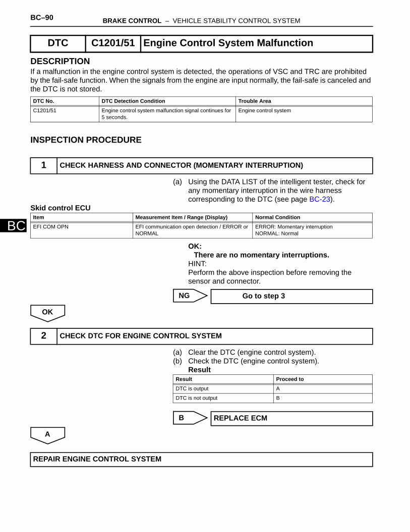
BC–90 BRAKE CONTROL – VEHICLE STABILITY CONTROL SYSTEM
BC
DESCRIPTIONIf a malfunction in the engine control system is detected, the operations of VSC and TRC are prohibited by the fail-safe function. When the signals from the engine are input normally, the fail-safe is canceled and the DTC is not stored.
INSPECTION PROCEDURE
(a) Using the DATA LIST of the intelligent tester, check for any momentary interruption in the wire harness corresponding to the DTC (see page BC-23).
Skid control ECU
OK:There are no momentary interruptions.
HINT:Perform the above inspection before removing the sensor and connector.
NG
OK
(a) Clear the DTC (engine control system).(b) Check the DTC (engine control system).
Result
B
A
DTC C1201/51 Engine Control System Malfunction
DTC No. DTC Detection Condition Trouble Area
C1201/51 Engine control system malfunction signal continues for 5 seconds.
Engine control system
1 CHECK HARNESS AND CONNECTOR (MOMENTARY INTERRUPTION)
Item Measurement Item / Range (Display) Normal Condition
EFI COM OPN EFI communication open detection / ERROR or NORMAL
ERROR: Momentary interruptionNORMAL: Normal
Go to step 3
2 CHECK DTC FOR ENGINE CONTROL SYSTEM
Result Proceed to
DTC is output A
DTC is not output B
REPLACE ECM
REPAIR ENGINE CONTROL SYSTEM
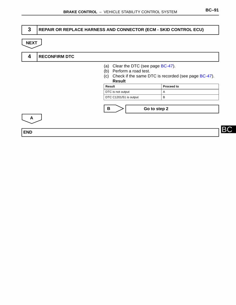
BRAKE CONTROL – VEHICLE STABILITY CONTROL SYSTEM BC–91
BC
NEXT
(a) Clear the DTC (see page BC-47).(b) Perform a road test.(c) Check if the same DTC is recorded (see page BC-47).
Result
B
A
3 REPAIR OR REPLACE HARNESS AND CONNECTOR (ECM - SKID CONTROL ECU)
4 RECONFIRM DTC
Result Proceed to
DTC is not output A
DTC C1201/51 is output B
Go to step 2
END

BC–92 BRAKE CONTROL – VEHICLE STABILITY CONTROL SYSTEM
BC
DESCRIPTIONThe circuit is used to send TRC and VSC control information from the skid control ECU to the ECM, and engine control information from the ECM to the skid control ECU.
INSPECTION PROCEDUREHINT:Check that the part numbers of the installed ECM and skid control ECU are correct before performing the following procedure.
(a) Clear the DTC (see page BC-47).(b) Start the engine.(c) Check if the same DTC is output (see page BC-47).
Result
B
A
DTC C1203/53 ECM Communication Circuit Malfunction
DTC No. DTC Detection Condition Trouble Area
C1203/53 Information relating to engine, drive source or destination stored in ECM does not match information stored in skid control ECU.
ECM
1 RECONFIRM DTC
Result Proceed to
DTC is output A
DTC is not output B
END
REPLACE ECM

BRAKE CONTROL – VEHICLE STABILITY CONTROL SYSTEM BC–93
BC
DESCRIPTIONThe ABS and TRACTION actuator (Skid control ECU) receives signals from the yaw rate and deceleration sensor via the CAN communication system. The yaw rate sensor has a built-in deceleration sensor and detects the vehicle's condition using 2 circuits (GL1, GL2). If there are problems in the bus lines between the yaw rate and deceleration sensor and the CAN communication system, DTCs U0123/62 (yaw rate sensor communication trouble) and U0124/95 (deceleration sensor communication trouble) are output. The DTCs are also output when the calibration has not been completed.
DTC C1210/36 Zero Point Calibration of Yaw Rate Sensor Undone
DTC C1336/39 Zero Point Calibration of Acceleration Sensor Undone
DTC No. DTC Detection Condition Trouble Area
C1210/36 Zero point calibration of yaw rate sensor not completed • ABS and TRACTION actuator (skid control ECU)• Zero point calibration incomplete• Yaw rate sensor
C1336/39 When either condition below is met:• Vehicle driven without completion of zero point
calibration• After zero point has been obtained, zero point
voltage of sensor not between 2.38 V and 2.62 V
• ABS and TRACTION actuator (skid control ECU)• Zero point calibration incomplete• Yaw rate sensor

BC–94 BRAKE CONTROL – VEHICLE STABILITY CONTROL SYSTEM
BC
WIRING DIAGRAM
INSPECTION PROCEDURENOTICE:When replacing the ABS and TRACTION actuator, perform the zero point calibration (see page BC-24).HINT:When DTC U0123/62, U0124/95 or U0126/63 is output together with DTC C1210/36 or C1336/39, inspect and repair trouble areas indicated by DTC U0123/62, U0124/95 or U0126/63 first.
(a) Check that the yaw rate sensor has been installed properly (see page BC-211).OK:
The sensor is tightened to the specified torque.The sensor is not tilted.
NG
1 CHECK YAW RATE SENSOR INSTALLATION
Skid Control ECU
CANH
CANH
CANL
CANL
IG
IG1
AM1
ALT
FL MAIN
GND
Yaw Rate Sensor
ECU-IG1
Ignition Switch
AM1 IG1
C126309E02
INSTALL YAW RATE SENSOR CORRECTLY
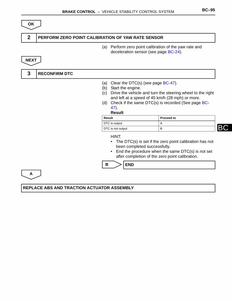
BRAKE CONTROL – VEHICLE STABILITY CONTROL SYSTEM BC–95
BC
OK
(a) Perform zero point calibration of the yaw rate and deceleration sensor (see page BC-24).
NEXT
(a) Clear the DTC(s) (see page BC-47).(b) Start the engine.(c) Drive the vehicle and turn the steering wheel to the right
and left at a speed of 45 km/h (28 mph) or more.(d) Check if the same DTC(s) is recorded (See page BC-
47).Result
HINT:• The DTC(s) is set if the zero point calibration has not
been completed successfully.• End the procedure when the same DTC(s) is not set
after completion of the zero point calibration.
B
A
2 PERFORM ZERO POINT CALIBRATION OF YAW RATE SENSOR
3 RECONFIRM DTC
Result Proceed to
DTC is output A
DTC is not output B
END
REPLACE ABS AND TRACTION ACTUATOR ASSEMBLY
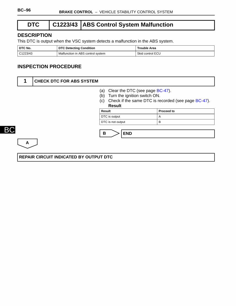
BC–96 BRAKE CONTROL – VEHICLE STABILITY CONTROL SYSTEM
BC
DESCRIPTIONThis DTC is output when the VSC system detects a malfunction in the ABS system.
INSPECTION PROCEDURE
(a) Clear the DTC (see page BC-47).(b) Turn the ignition switch ON.(c) Check if the same DTC is recorded (see page BC-47).
Result
B
A
DTC C1223/43 ABS Control System Malfunction
DTC No. DTC Detecting Condition Trouble Area
C1223/43 Malfunction in ABS control system Skid control ECU
1 CHECK DTC FOR ABS SYSTEM
Result Proceed to
DTC is output A
DTC is not output B
END
REPAIR CIRCUIT INDICATED BY OUTPUT DTC

BRAKE CONTROL – VEHICLE STABILITY CONTROL SYSTEM BC–97
BC
DESCRIPTIONThe steering sensor signal is sent to the skid control ECU via the CAN communication system. When there is a malfunction in the CAN communication system, it is detected by the steering sensor zero point malfunction diagnostic function.
WIRING DIAGRAM
DTC C1231/31 Steering Angle Sensor Circuit Malfunction
DTC No. DTC Detection Condition Trouble Area
C1231/31 When IG1 terminal voltage 9.5 V or more, steering angle sensor malfunction signal received.
• Steering sensor • Steering sensor circuit• Steering sensor power supply• CAN communication system
Skid Control ECU
CANH
CANH
CANL
CANL
IG
IG1
BAT
ESS
Steering Sensor
ECU-IG1
ECU-BMAIN
FL MAIN
AM1
ALT
Ignition Switch
AM1 IG1
C126311E02
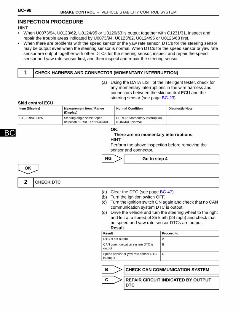
BC–98 BRAKE CONTROL – VEHICLE STABILITY CONTROL SYSTEM
BC
INSPECTION PROCEDUREHINT:• When U0073/94, U0123/62, U0124/95 or U0126/63 is output together with C1231/31, inspect and
repair the trouble areas indicated by U0073/94, U0123/62, U0124/95 or U0126/63 first.• When there are problems with the speed sensor or the yaw rate sensor, DTCs for the steering sensor
may be output even when the steering sensor is normal. When DTCs for the speed sensor or yaw rate sensor are output together with other DTCs for the steering sensor, inspect and repair the speed sensor and yaw rate sensor first, and then inspect and repair the steering sensor.
(a) Using the DATA LIST of the intelligent tester, check for any momentary interruptions in the wire harness and connectors between the skid control ECU and the steering sensor (see page BC-23).
Skid control ECU
OK:There are no momentary interruptions.
HINT:Perform the above inspection before removing the sensor and connector.
NG
OK
(a) Clear the DTC (see page BC-47).(b) Turn the ignition switch OFF.(c) Turn the ignition switch ON again and check that no CAN
communication system DTC is output.(d) Drive the vehicle and turn the steering wheel to the right
and left at a speed of 35 km/h (24 mph) and check that no speed and yaw rate sensor DTCs are output.Result
B
C
1 CHECK HARNESS AND CONNECTOR (MOMENTARY INTERRUPTION)
Item (Display) Measurement Item / Range (Display)
Normal Condition Diagnostic Note
STEERING OPN Steering angle sensor open detection / ERROR or NORMAL
ERROR: Momentary interruptionNORMAL: Normal
-
Go to step 4
2 CHECK DTC
Result Proceed to
DTC is not output A
CAN communication system DTC is output
B
Speed sensor or yaw rate sensor DTC is output
C
CHECK CAN COMMUNICATION SYSTEM
REPAIR CIRCUIT INDICATED BY OUTPUT DTC

BRAKE CONTROL – VEHICLE STABILITY CONTROL SYSTEM BC–99
BC
A
(a) Remove the steering wheel assembly and the column cover.
(b) Disconnect the E11 sensor connector.(c) Measure the voltage of the wire harness side connector.
Standard voltage
(d) Measure the resistance of the wire harness side connector.Standard resistance
NG
OK
NEXT
(a) Clear the DTC (see page BC-47).(b) Start the engine.(c) Drive the vehicle and turn the steering wheel to the right
and left at a speed of 45 km/h (28 mph) or more for several seconds.
(d) Check if the same DTC is recorded (see page BC-47).Result
B
3 CHECK WIRE HARNESS (STEERING SENSOR - BATTERY AND BODY GROUND)
1 2 3 4 5 6 7 8 9 10
Wire Harness Side
E11
IG ESS BATC130038E02
Tester Connection Condition Specified Condition
E11-1(IG) - Body ground Ignition switch ON 10 to 14 V
E11-3 (BAT) - Body ground
Always 10 to 14 V
Tester Connection Specified Condition
E11-2 (ESS) - Body ground Below 1Ω
REPAIR OR REPLACE HARNESS AND CONNECTOR
REPLACE STEERING SENSOR
4 REPAIR OR REPLACE HARNESS AND CONNECTOR (STEERING SENSOR TO SKID CONTROL ECU)
5 RECONFIRM DTC
Result Proceed to
DTC is not output A
DTC is output B
Go to step 2

BC–100 BRAKE CONTROL – VEHICLE STABILITY CONTROL SYSTEM
BC
A
END
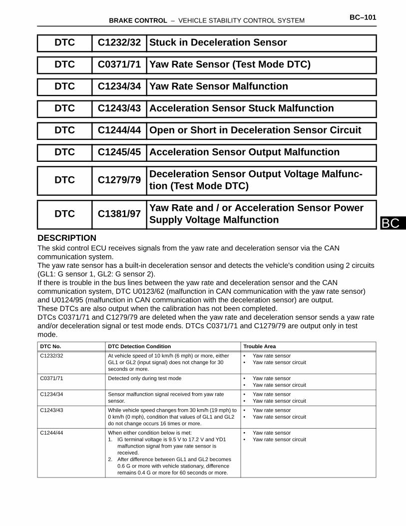
BRAKE CONTROL – VEHICLE STABILITY CONTROL SYSTEM BC–101
BCDESCRIPTIONThe skid control ECU receives signals from the yaw rate and deceleration sensor via the CAN communication system.The yaw rate sensor has a built-in deceleration sensor and detects the vehicle's condition using 2 circuits (GL1: G sensor 1, GL2: G sensor 2).If there is trouble in the bus lines between the yaw rate and deceleration sensor and the CAN communication system, DTC U0123/62 (malfunction in CAN communication with the yaw rate sensor) and U0124/95 (malfunction in CAN communication with the deceleration sensor) are output.These DTCs are also output when the calibration has not been completed.DTCs C0371/71 and C1279/79 are deleted when the yaw rate and deceleration sensor sends a yaw rate and/or deceleration signal or test mode ends. DTCs C0371/71 and C1279/79 are output only in test mode.
DTC C1232/32 Stuck in Deceleration Sensor
DTC C0371/71 Yaw Rate Sensor (Test Mode DTC)
DTC C1234/34 Yaw Rate Sensor Malfunction
DTC C1243/43 Acceleration Sensor Stuck Malfunction
DTC C1244/44 Open or Short in Deceleration Sensor Circuit
DTC C1245/45 Acceleration Sensor Output Malfunction
DTC C1279/79 Deceleration Sensor Output Voltage Malfunc-tion (Test Mode DTC)
DTC C1381/97 Yaw Rate and / or Acceleration Sensor Power Supply Voltage Malfunction
DTC No. DTC Detection Condition Trouble Area
C1232/32 At vehicle speed of 10 km/h (6 mph) or more, either GL1 or GL2 (input signal) does not change for 30 seconds or more.
• Yaw rate sensor• Yaw rate sensor circuit
C0371/71 Detected only during test mode • Yaw rate sensor• Yaw rate sensor circuit
C1234/34 Sensor malfunction signal received from yaw rate sensor.
• Yaw rate sensor• Yaw rate sensor circuit
C1243/43 While vehicle speed changes from 30 km/h (19 mph) to 0 km/h (0 mph), condition that values of GL1 and GL2 do not change occurs 16 times or more.
• Yaw rate sensor• Yaw rate sensor circuit
C1244/44 When either condition below is met:1. IG terminal voltage is 9.5 V to 17.2 V and YD1
malfunction signal from yaw rate sensor is received.
2. After difference between GL1 and GL2 becomes 0.6 G or more with vehicle stationary, difference remains 0.4 G or more for 60 seconds or more.
• Yaw rate sensor• Yaw rate sensor circuit
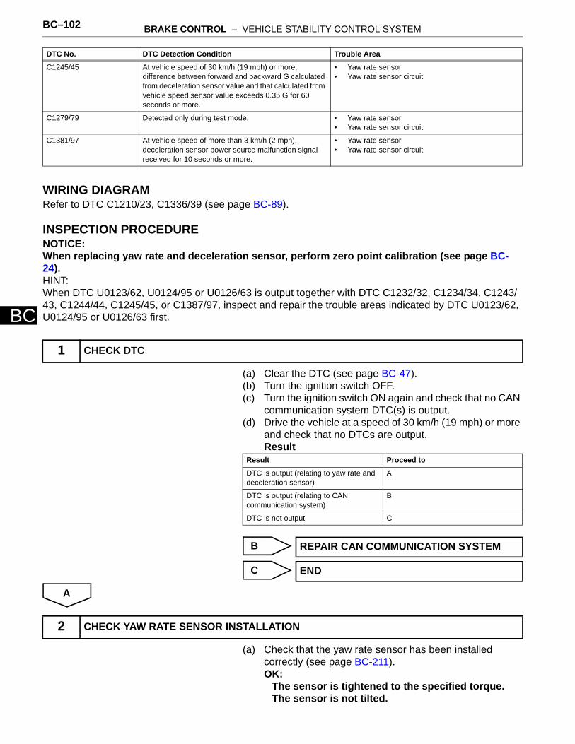
BC–102 BRAKE CONTROL – VEHICLE STABILITY CONTROL SYSTEM
BC
WIRING DIAGRAMRefer to DTC C1210/23, C1336/39 (see page BC-89).
INSPECTION PROCEDURENOTICE:When replacing yaw rate and deceleration sensor, perform zero point calibration (see page BC-24).HINT:When DTC U0123/62, U0124/95 or U0126/63 is output together with DTC C1232/32, C1234/34, C1243/43, C1244/44, C1245/45, or C1387/97, inspect and repair the trouble areas indicated by DTC U0123/62, U0124/95 or U0126/63 first.
(a) Clear the DTC (see page BC-47).(b) Turn the ignition switch OFF.(c) Turn the ignition switch ON again and check that no CAN
communication system DTC(s) is output.(d) Drive the vehicle at a speed of 30 km/h (19 mph) or more
and check that no DTCs are output.Result
B
C
A
(a) Check that the yaw rate sensor has been installed correctly (see page BC-211).OK:
The sensor is tightened to the specified torque.The sensor is not tilted.
C1245/45 At vehicle speed of 30 km/h (19 mph) or more, difference between forward and backward G calculated from deceleration sensor value and that calculated from vehicle speed sensor value exceeds 0.35 G for 60 seconds or more.
• Yaw rate sensor• Yaw rate sensor circuit
C1279/79 Detected only during test mode. • Yaw rate sensor• Yaw rate sensor circuit
C1381/97 At vehicle speed of more than 3 km/h (2 mph), deceleration sensor power source malfunction signal received for 10 seconds or more.
• Yaw rate sensor• Yaw rate sensor circuit
1 CHECK DTC
DTC No. DTC Detection Condition Trouble Area
Result Proceed to
DTC is output (relating to yaw rate and deceleration sensor)
A
DTC is output (relating to CAN communication system)
B
DTC is not output C
REPAIR CAN COMMUNICATION SYSTEM
END
2 CHECK YAW RATE SENSOR INSTALLATION

BRAKE CONTROL – VEHICLE STABILITY CONTROL SYSTEM BC–103
BC
NG
OK
(a) Disconnect the K6 sensor connector. (b) Measure the voltage of the wire harness side connector.
Standard voltage
(c) Measure the resistance of the wire harness side connector.Standard resistance
NG
OK
INSTALL YAW RATE SENSOR CORRECTLY
3 CHECK WIRE HARNESS (YAW RATE SENSOR - BATTERY AND BODY GROUND)
Wire Harness Side
K6
IG1GND
C121701E02
Tester Connection Condition Specified Condition
K6-5 (IG) - Body ground Ignition switch ON 10 to 14 V
Tester Connection Specified Condition
K6-1 (GND) - Body ground Below 1 Ω
REPAIR OR REPLACE HARNESS AND CONNECTOR
REPLACE YAW RATE SENSOR
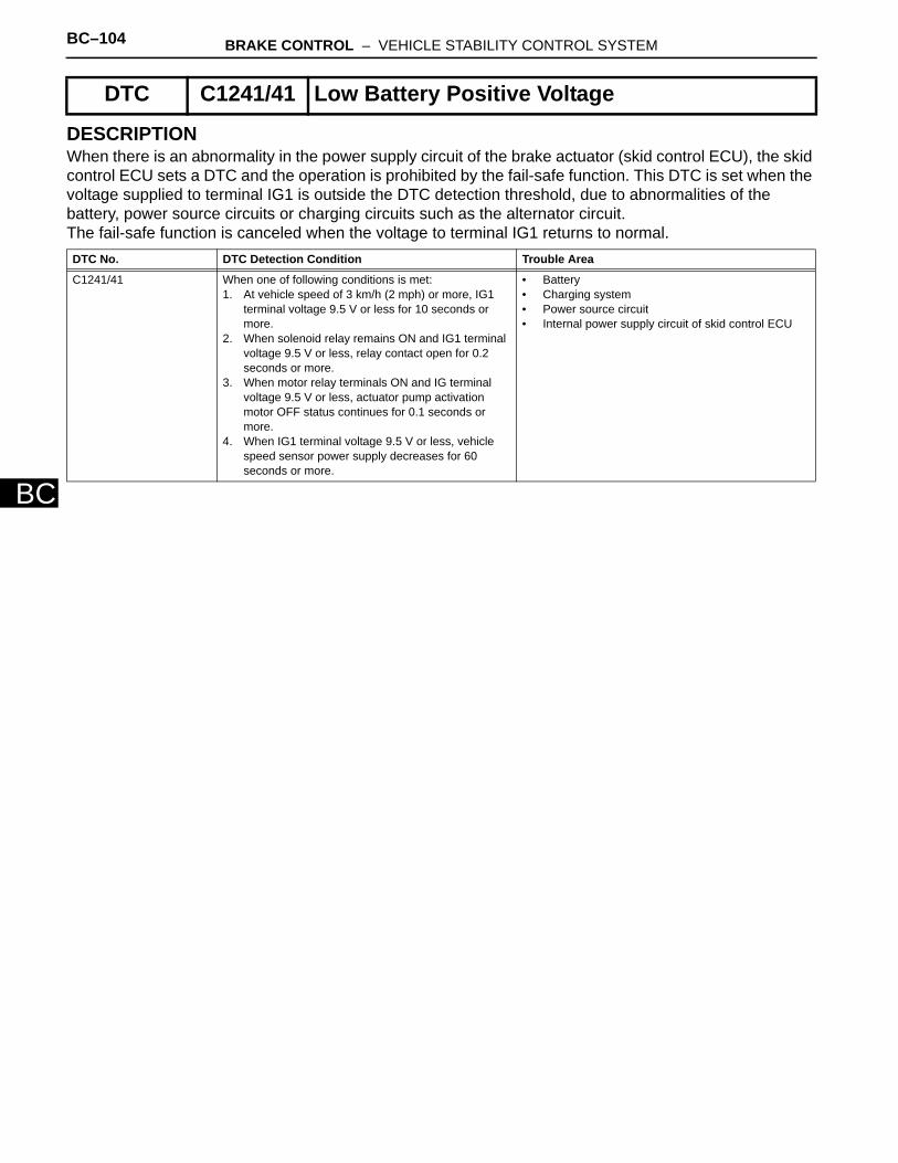
BC–104 BRAKE CONTROL – VEHICLE STABILITY CONTROL SYSTEM
BC
DESCRIPTIONWhen there is an abnormality in the power supply circuit of the brake actuator (skid control ECU), the skid control ECU sets a DTC and the operation is prohibited by the fail-safe function. This DTC is set when the voltage supplied to terminal IG1 is outside the DTC detection threshold, due to abnormalities of the battery, power source circuits or charging circuits such as the alternator circuit. The fail-safe function is canceled when the voltage to terminal IG1 returns to normal.
DTC C1241/41 Low Battery Positive Voltage
DTC No. DTC Detection Condition Trouble Area
C1241/41 When one of following conditions is met:1. At vehicle speed of 3 km/h (2 mph) or more, IG1
terminal voltage 9.5 V or less for 10 seconds or more.
2. When solenoid relay remains ON and IG1 terminal voltage 9.5 V or less, relay contact open for 0.2 seconds or more.
3. When motor relay terminals ON and IG terminal voltage 9.5 V or less, actuator pump activation motor OFF status continues for 0.1 seconds or more.
4. When IG1 terminal voltage 9.5 V or less, vehicle speed sensor power supply decreases for 60 seconds or more.
• Battery• Charging system• Power source circuit• Internal power supply circuit of skid control ECU
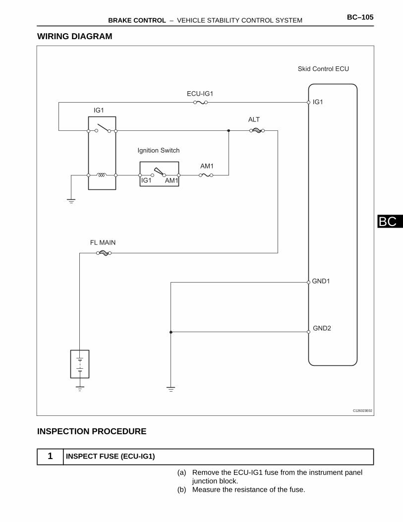
BRAKE CONTROL – VEHICLE STABILITY CONTROL SYSTEM BC–105
BC
WIRING DIAGRAM
INSPECTION PROCEDURE
(a) Remove the ECU-IG1 fuse from the instrument panel junction block.
(b) Measure the resistance of the fuse.
1 INSPECT FUSE (ECU-IG1)
IG1
Skid Control ECU
ECU-IG1
IG1
ALT
IG1 AM1
AM1
FL MAIN
GND1
GND2
Ignition Switch
C126323E02
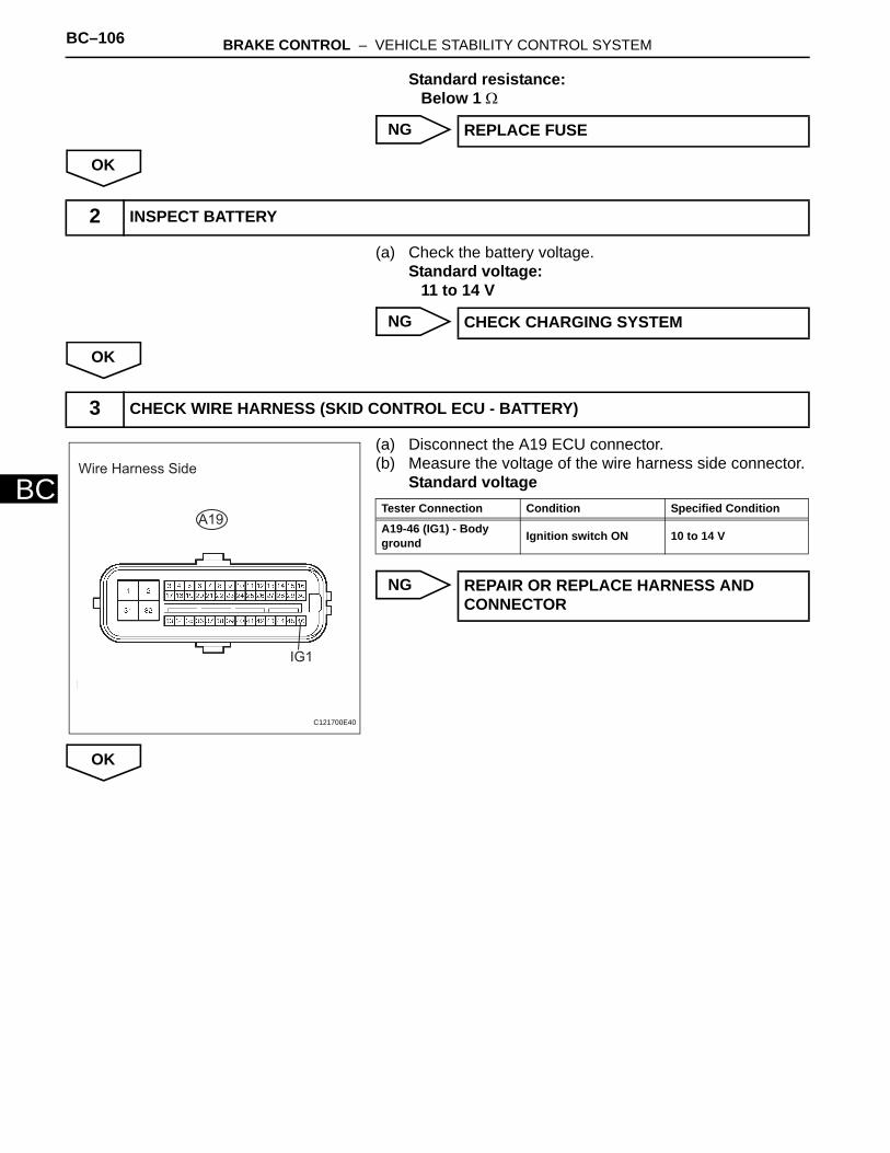
BC–106 BRAKE CONTROL – VEHICLE STABILITY CONTROL SYSTEM
BC
Standard resistance:Below 1 Ω
NG
OK
(a) Check the battery voltage.Standard voltage:
11 to 14 V
NG
OK
(a) Disconnect the A19 ECU connector.(b) Measure the voltage of the wire harness side connector.
Standard voltage
NG
OK
REPLACE FUSE
2 INSPECT BATTERY
CHECK CHARGING SYSTEM
3 CHECK WIRE HARNESS (SKID CONTROL ECU - BATTERY)
Wire Harness Side
A19
IG1
C121700E40
Tester Connection Condition Specified Condition
A19-46 (IG1) - Body ground Ignition switch ON 10 to 14 V
REPAIR OR REPLACE HARNESS AND CONNECTOR
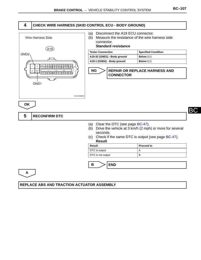
BRAKE CONTROL – VEHICLE STABILITY CONTROL SYSTEM BC–107
BC
(a) Disconnect the A19 ECU connector.(b) Measure the resistance of the wire harness side
connector.Standard resistance
NG
OK
(a) Clear the DTC (see page BC-47).(b) Drive the vehicle at 3 km/h (2 mph) or more for several
seconds.(c) Check if the same DTC is output (see page BC-47).
Result
B
A
4 CHECK WIRE HARNESS (SKID CONTROL ECU - BODY GROUND)
Wire Harness Side
A19
GND1
GND2
C121700E49
Tester Connection Specified Condition
A19-32 (GND1) - Body ground Below 1 Ω
A19-1 (GND2) - Body ground Below 1 Ω
REPAIR OR REPLACE HARNESS AND CONNECTOR
5 RECONFIRM DTC
Result Proceed to
DTC is output A
DTC is not output B
END
REPLACE ABS AND TRACTION ACTUATOR ASSEMBLY

BC–108 BRAKE CONTROL – VEHICLE STABILITY CONTROL SYSTEM
BC
DESCRIPTIONThe master cylinder pressure sensor is connected to the skid control ECU in the ABS and TRACTION actuator.DTC C1281/81 can be detected when the master cylinder pressure sensor sends a master cylinder pressure signal or test mode ends. DTC C1281/81 is output only in test mode.
INSPECTION PROCEDURENOTICE:When replacing the ABS and TRACTION actuator, perform zero point calibration (see page BC-24).
(a) Check the DATA LIST for proper functioning of the stop light switch.
Skid control ECU
OK:ON (brake pedal is depressed) appears on the screen.
NG
OK
DTC C1246/46 Master Cylinder Pressure Sensor Malfunction
DTC C1281/81 Master Cylinder Pressure Sensor Output Mal-function (Test Mode DTC)
DTC No. DTC Detection Condition Trouble Area
C1246/46 When one of following conditions is met:1. At vehicle speed of 7 km/h (4.3 mph) or more, when
PMC terminal voltage over 0.86 V, voltage does not change by 0.005 V or more for 30 seconds.
2. Noise occurs in the PMC terminal 7 times or more within 5 seconds.
3. When stop light switch OFF, PMC terminal voltage more than 0.86 V or less than 0.3 V for 5 seconds or more.
4. With IG1 terminal voltage between 9.5 V and 17.2 V, VCM terminal voltage not between 4.4 V and 5.6 V for 1.2 seconds or more.
5. When VCM terminal voltage between 4.4 V and 5.6 V, PCM terminal voltage not between 0.14 V and 4.85 V for 1.2 seconds or more.
• Master cylinder pressure sensor• Master cylinder pressure sensor circuit• Stop light switch circuit• ABS and TRACTION actuator
C1281/81 Detected only during test mode. • Master cylinder pressure sensor• Master cylinder pressure sensor circuit• Stop light switch circuit• ABS and TRACTION actuator
1 READ VALUE OF INTELLIGENT TESTER (STOP LIGHT SWITCH)
Item (Display) Measurement Item / Range (Display)
Normal Condition Diagnostic Note
STOP LAMP SW Stop light switch / ON or OFF ON: Brake pedal appliedOFF: Brake pedal released
-
CHECK STOP LIGHT SWITCH CIRCUIT

BRAKE CONTROL – VEHICLE STABILITY CONTROL SYSTEM BC–109
BC
(a) Check the DATA LIST for proper functioning of the master cylinder pressure sensor.
Skid control ECU
OK:When the pedal is depressed, the sensor output voltage increases.
NG
OK
(a) Clear the DTC(s) (see page BC-47).(b) Drive the vehicle at a speed of 30 km/h (18 mph) or more
and perform a braking test (decelerate the vehicle by depressing the brake pedal).
(c) Check if the same DTC(s) is recorded (see page BC-47).Result
B
A
2 READ VALUE OF INTELLIGENT TESTER (MASTER CYLINDER PRESSURE SENSOR)
Item (Display) Measurement Item / Range (Display)
Normal Condition Diagnostic Note
MAS CYL PRESS 1 Master cylinder pressure sensor 1 reading / min.: 0 V, max.: 5 V
When brake pedal released: 0.3 to 0.9 V
-
REPLACE ABS AND TRACTION ACTUATOR ASSEMBLY
3 RECONFIRM DTC
Result Proceed to
DTC is output A
DTC is not output B
END
REPLACE ABS AND TRACTION ACTUATOR ASSEMBLY
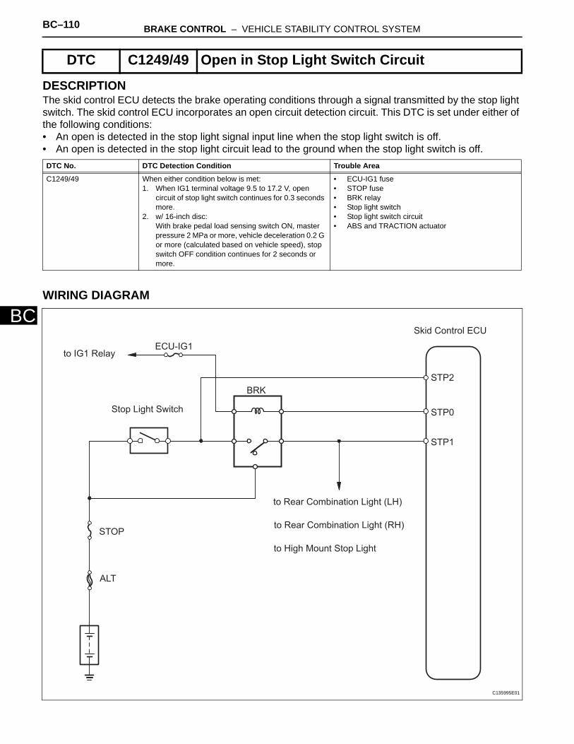
BC–110 BRAKE CONTROL – VEHICLE STABILITY CONTROL SYSTEM
BC
DESCRIPTIONThe skid control ECU detects the brake operating conditions through a signal transmitted by the stop light switch. The skid control ECU incorporates an open circuit detection circuit. This DTC is set under either of the following conditions:• An open is detected in the stop light signal input line when the stop light switch is off.• An open is detected in the stop light circuit lead to the ground when the stop light switch is off.
WIRING DIAGRAM
DTC C1249/49 Open in Stop Light Switch Circuit
DTC No. DTC Detection Condition Trouble Area
C1249/49 When either condition below is met:1. When IG1 terminal voltage 9.5 to 17.2 V, open
circuit of stop light switch continues for 0.3 seconds more.
2. w/ 16-inch disc:With brake pedal load sensing switch ON, master pressure 2 MPa or more, vehicle deceleration 0.2 G or more (calculated based on vehicle speed), stop switch OFF condition continues for 2 seconds or more.
• ECU-IG1 fuse• STOP fuse• BRK relay• Stop light switch• Stop light switch circuit• ABS and TRACTION actuator
Skid Control ECU
STP2
STP0
STP1
to Rear Combination Light (LH)
to Rear Combination Light (RH)
to High Mount Stop Light
BRK
ECU-IG1to IG1 Relay
ALT
STOP
Stop Light Switch
C135995E01
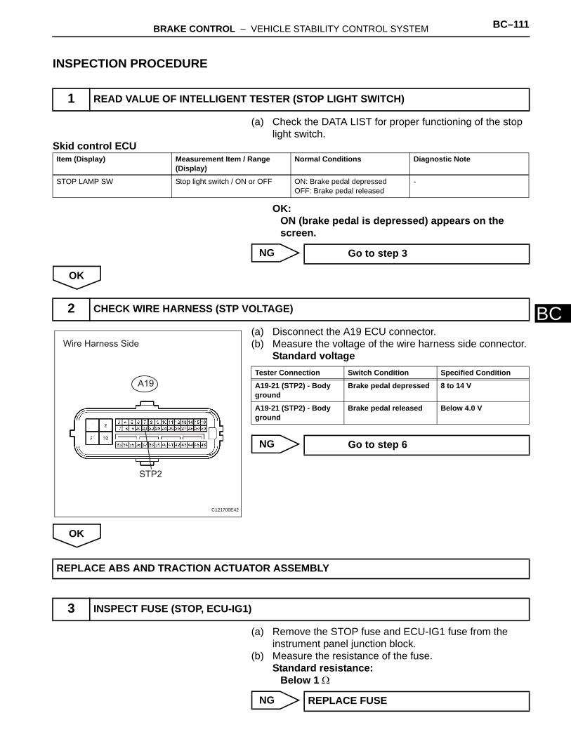
BRAKE CONTROL – VEHICLE STABILITY CONTROL SYSTEM BC–111
BC
INSPECTION PROCEDURE
(a) Check the DATA LIST for proper functioning of the stop light switch.
Skid control ECU
OK:ON (brake pedal is depressed) appears on the screen.
NG
OK
(a) Disconnect the A19 ECU connector.(b) Measure the voltage of the wire harness side connector.
Standard voltage
NG
OK
(a) Remove the STOP fuse and ECU-IG1 fuse from the instrument panel junction block.
(b) Measure the resistance of the fuse.Standard resistance:
Below 1 Ω
NG
1 READ VALUE OF INTELLIGENT TESTER (STOP LIGHT SWITCH)
Item (Display) Measurement Item / Range (Display)
Normal Conditions Diagnostic Note
STOP LAMP SW Stop light switch / ON or OFF ON: Brake pedal depressedOFF: Brake pedal released
-
Go to step 3
2 CHECK WIRE HARNESS (STP VOLTAGE)
Wire Harness Side
A19
STP2
C121700E42
Tester Connection Switch Condition Specified Condition
A19-21 (STP2) - Body ground
Brake pedal depressed 8 to 14 V
A19-21 (STP2) - Body ground
Brake pedal released Below 4.0 V
Go to step 6
REPLACE ABS AND TRACTION ACTUATOR ASSEMBLY
3 INSPECT FUSE (STOP, ECU-IG1)
REPLACE FUSE

BC–112 BRAKE CONTROL – VEHICLE STABILITY CONTROL SYSTEM
BC
OK
(a) Remove the stop light control relay from the engine room No. 1 relay block.
(b) Measure the resistance of the relay.
NG
OK
(a) Disconnect the stop light switch connector.(b) Measure the resistance of the switch.
Standard resistance
NG
OK
4 INSPECT STOP LIGHT CONTROL RELAY (Marking: BRK)
1
1
2
2
3
3
4
4
55
A087121E01
Tester Connection Specified Condition
3 - 4 Below 1 Ω
3 - 5 10 kΩ or higher
3 - 4 10 kΩ or higher(when battery voltage is applied to terminals 1 and 2)
3 - 5 Below 1 Ω(when battery voltage is applied to terminals 1 and 2)
REPLACE STOP LIGHT CONTROL RELAY
5 INSPECT STOP LIGHT SWITCH ASSEMBLY
Pin
Not Pushed Pushed
2 1
34
C108891E01
Tester Connection Switch Condition Specified Condition
1 - 2 Pin not pushed Below 1 Ω
1 - 2 Pin pushed 10 kΩ or higher
3 - 4 Pin not pushed 10 kΩ or higher
3 - 4 Pin pushed Below 1 Ω
REPLACE STOP LIGHT SWITCH ASSEMBLY

BRAKE CONTROL – VEHICLE STABILITY CONTROL SYSTEM BC–113
BC
(a) Disconnect the A19 ECU connector.(b) Disconnect the A3 switch connector.(c) Measure the resistance of the wire harness side
connectors.Standard resistance
NG
OK
(a) Clear the DTC (see page BC-47).(b) Check if the same DTC is output (see page BC-47).
Result
B
A
6 CHECK WIRE HARNESS (SKID CONTROL ECU - STOP LIGHT SWITCH)
Skid Control ECU
Wire Harness Side
A19
Stop Light Switch Assembly
A3
STP2
C121702E05
Tester Connection Specified Condition
A19-21 (STP2) - A3-1 Below 1 Ω
REPAIR OR REPLACE HARNESS AND CONNECTOR
7 RECONFIRM DTC
Result Proceed to
DTC is output A
DTC is not output B
END
REPLACE ABS AND TRACTION ACTUATOR ASSEMBLY
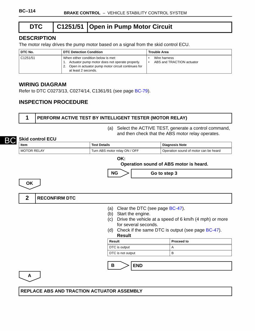
BC–114 BRAKE CONTROL – VEHICLE STABILITY CONTROL SYSTEM
BC
DESCRIPTIONThe motor relay drives the pump motor based on a signal from the skid control ECU.
WIRING DIAGRAMRefer to DTC C0273/13, C0274/14, C1361/91 (see page BC-79).
INSPECTION PROCEDURE
(a) Select the ACTIVE TEST, generate a control command, and then check that the ABS motor relay operates.
Skid control ECU
OK:Operation sound of ABS motor is heard.
NG
OK
(a) Clear the DTC (see page BC-47).(b) Start the engine.(c) Drive the vehicle at a speed of 6 km/h (4 mph) or more
for several seconds.(d) Check if the same DTC is output (see page BC-47).
Result
B
A
DTC C1251/51 Open in Pump Motor Circuit
DTC No. DTC Detection Condition Trouble Area
C1251/51 When either condition below is met:1. Actuator pump motor does not operate properly.2. Open in actuator pump motor circuit continues for
at least 2 seconds.
• Wire harness• ABS and TRACTION actuator
1 PERFORM ACTIVE TEST BY INTELLIGENT TESTER (MOTOR RELAY)
Item Test Details Diagnosis Note
MOTOR RELAY Turn ABS motor relay ON / OFF Operation sound of motor can be heard
Go to step 3
2 RECONFIRM DTC
Result Proceed to
DTC is output A
DTC is not output B
END
REPLACE ABS AND TRACTION ACTUATOR ASSEMBLY

BRAKE CONTROL – VEHICLE STABILITY CONTROL SYSTEM BC–115
BC
(a) Remove the ABS1 H-fuse from the engine room No. 1 relay block.
(b) Measure the resistance of the fuse.Standard resistance:
Below 1 Ω
NG
OK
(a) Disconnect the A19 connector.(b) Measure the resistance of the wire harness side
connector.Standard resistance
(c) Measure the voltage of the wire harness side connector.Standard voltage
NG
OK
3 INSPECT FUSE (ABS1)
REPLACE FUSE
4 CHECK WIRE HARNESS (SKID CONTROL ECU - BATTERY AND BODY GROUND)
Wire Harness Side
A19
GND1
GND2 +BM
C121700E43
Tester Connection Specified Condition
A19-32 (GND1) - Body ground Below 1 Ω
A19-1 (GND2) - Body ground Below 1 Ω
Tester Connection Specified Condition
A19-2 (BM) - Body ground 10 to 14 V
REPAIR OR REPLACE HARNESS AND CONNECTOR
REPLACE ABS AND TRACTION ACTUATOR ASSEMBLY
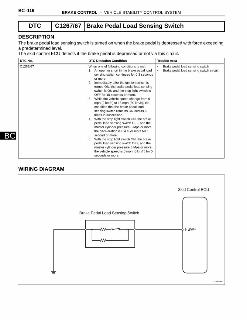
BC–116 BRAKE CONTROL – VEHICLE STABILITY CONTROL SYSTEM
BC
DESCRIPTIONThe brake pedal load sensing switch is turned on when the brake pedal is depressed with force exceeding a predetermined level.The skid control ECU detects if the brake pedal is depressed or not via this circuit.
WIRING DIAGRAM
DTC C1267/67 Brake Pedal Load Sensing Switch
DTC No. DTC Detection Condition Trouble Area
C1267/67 When one of following conditions is met:1. An open or short in the brake pedal load
sensing switch continues for 0.3 seconds or more.
2. Immediately after the ignition switch is turned ON, the brake pedal load sensing switch is ON and the stop light switch is OFF for 10 seconds or more.
3. While the vehicle speed change from 0 mph (0 km/h) to 18 mph (30 km/h), the condition that the brake pedal load sensing switch remains ON occurs 5 times in succession.
4. With the stop light switch ON, the brake pedal load sensing switch OFF, and the master cylinder pressure 6 Mpa or more, the deceleration is 0.4 G or more for 1 second or more.
5. With the stop light switch ON, the brake pedal load sensing switch OFF, and the master cylinder pressure 6 Mpa or more, the vehicle speed is 0 mph (0 km/h) for 5 seconds or more.
• Brake pedal load sensing switch• Brake pedal load sensing switch circuit
Skid Control ECU
Brake Pedal Load Sensing Switch
FSW+
C126312E01

BRAKE CONTROL – VEHICLE STABILITY CONTROL SYSTEM BC–117
BC
INSPECTION PROCEDURENOTICE:When replacing the brake actuator assembly, perform zero point calibration (see page BC-24).HINT:If DTC C1249/49 is output, repair it before repairing DTC C1267/67 based on the flowchart below.
(a) Check the DATA LIST for proper functioning of the brake pedal load sensing switch.
Skid control ECU
OK:ON (brake pedal is depressed) appears on the screen.
OK
NG
NOTICE:• Do not remove the brake pedal load sensing switch
from the brake pedal.• When there is a malfunction in the brake pedal load
sensing switch, replace the brake pedal.(a) Turn the ignition switch OFF.
1 READ VALUE OF INTELLIGENT TESTER (BRAKE PEDAL LOAD SENSING SWITCH)
Item (Display) Measurement Item / Range (Display)
Normal Condition Diagnostic Note
BRAKE PEDAL SW Brake pedal load sensing switch / ON or OFF
ON: Depressed brake pedalOFF: Released brake pedal
-
Go to step 4
2 INSPECT BRAKE PEDAL LOAD SENSING SWITCH
Brake Pedal Load
Sensing Switch
Brake Pedal Support
Brake Pedal Released (ON)
Brake Pedal Depressed (OFF)
2 1
C129075E02

BC–118 BRAKE CONTROL – VEHICLE STABILITY CONTROL SYSTEM
BC
(b) Disconnect the brake pedal load sensing switch connector.
(c) Measure the resistance of the switch.Standard resistance
NG
OK
(a) Disconnect the A19 ECU connector.(b) Measure the resistance of the wire harness side
connectors.Standard resistance
NG
OK
(a) Clear the DTC (see page BC-47).(b) Check if the same DTC is recorded (see page BC-47).
Result
B
Tester Connection Condition Specified Condition
2 - 1 Brake pedal depressed (OFF) 0.95 to 1.05 kΩ
2 - 1 Brake pedal released (ON) 202.4 to 223.7 Ω
REPLACE BRAKE PEDAL SUPPORT ASSEMBLY
3 CHECK WIRE HARNESS (SKID CONTROL ECU - BRAKE PEDAL LOAD SENSING SWITCH)
Skid Control ECU
Wire Harness Side
A19
Brake Pedal Load Sensing Switch
A2
FSW+
C110685E06
Tester Connection Specified Condition
A19-7 (FSW+) - A2-2 Below 1 Ω
19-7 (FSW+) - Body ground 10 kΩ or higher
A2-1 - Body ground Below 1 Ω
REPAIR OR REPLACE HARNESS AND CONNECTOR
4 RECONFIRM DTC
Result Proceed to
DTC (C1267/67) is not output A
DTC (C1267/67) is output B
REPLACE ABS AND TRACTION ACTUATOR ASSEMBLY

BRAKE CONTROL – VEHICLE STABILITY CONTROL SYSTEM BC–119
BC
A
USE SIMULATION METHOD TO CHECK

BC–120 BRAKE CONTROL – VEHICLE STABILITY CONTROL SYSTEM
BC
DESCRIPTIONThe skid control ECU learns the steering sensor zero point every time the ignition switch is turned ON and the vehicle is driven at 35 km/h (22 mph) or more for approximately 5 seconds. The ECU also stores the previous zero point.If front wheel alignment or the steering wheel position is adjusted without disconnecting the negative battery terminal, or if the yaw rate and deceleration sensor zero point is not set after the adjustments have been completed, the skid control ECU detects the difference between the previously stored zero point and the newly learned zero point and outputs this DTC to indicate a poor adjustment.Indication of the steering sensor zero point malfunction is canceled by turning the ignition switch OFF.
INSPECTION PROCEDURENOTICE:When replacing the ABS and TRACTION actuator, perform zero point calibration (see page BC-24).
(a) Perform the zero point calibration of the yaw rate and deceleration sensor (see page BC-24).HINT:• When the stored zero point of the yaw rate and
deceleration sensor is erased, the steering sensor zero point is also erased.
• If the zero point and output value of the yaw rate and deceleration sensor and the output values of the speed sensors are not normal, the steering sensor zero point cannot be learned normally even if the vehicle is driven straight ahead at 35 km/h (22 mph) or more.
NEXT
(a) Drive the vehicle straight ahead at 35 km/h (22 mph) or more for 5 seconds or more.
(b) Check that the centered position of the steering wheel is correctly set while driving straight ahead.HINT:If the front wheel alignment and steering position are adjusted due to an incorrectly centered position of the steering wheel, set the yaw rate and deceleration sensor zero point again after the adjustments are completed.
DTC C1290/66 Steering Angle Sensor Zero Point Malfunction
DTC No. DTC Detection Condition Trouble Area
C1290/66 Steering sensor zero point calibration position differs significantly from recorded value
• Yaw rate and deceleration sensor zero point calibration incomplete
• Poor adjustment of centered position of steering wheel
• Poor adjustment of front wheel alignment
1 PERFORM YAW RATE AND DECELERATION SENSOR ZERO POINT CALIBRATION
2 CHECK STEERING SENSOR

BRAKE CONTROL – VEHICLE STABILITY CONTROL SYSTEM BC–121
BC
OK:The center position of the steering wheel is correctly set.
NG
OK
(a) Turn the ignition switch OFF.(b) Clear the DTC (see page BC-47).(c) Check if the same DTC is recorded (see page BC-47).Result
B
A
ADJUST FRONT WHEEL ALIGNMENT
3 RECONFIRM DTC
Result Proceed to
DTC (C1290/66) is not output A
DTC (C1290/66) is output B
REPLACE ABS AND TRACTION ACTUATOR ASSEMBLY
USE SIMULATION METHOD TO CHECK
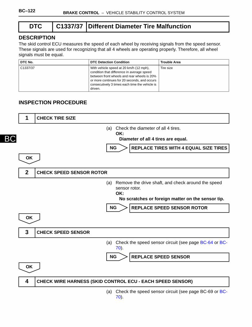
BC–122 BRAKE CONTROL – VEHICLE STABILITY CONTROL SYSTEM
BC
DESCRIPTIONThe skid control ECU measures the speed of each wheel by receiving signals from the speed sensor. These signals are used for recognizing that all 4 wheels are operating properly. Therefore, all wheel signals must be equal.
INSPECTION PROCEDURE
(a) Check the diameter of all 4 tires.OK:
Diameter of all 4 tires are equal.
NG
OK
(a) Remove the drive shaft, and check around the speed sensor rotor.OK:
No scratches or foreign matter on the sensor tip.
NG
OK
(a) Check the speed sensor circuit (see page BC-64 or BC-70).
NG
OK
(a) Check the speed sensor circuit (see page BC-69 or BC-70).
DTC C1337/37 Different Diameter Tire Malfunction
DTC No. DTC Detection Condition Trouble Area
C1337/37 With vehicle speed at 20 km/h (12 mph), condition that difference in average speed between front wheels and rear wheels is 20% or more continues for 20 seconds, and occurs consecutively 3 times each time the vehicle is driven.
Tire size
1 CHECK TIRE SIZE
REPLACE TIRES WITH 4 EQUAL SIZE TIRES
2 CHECK SPEED SENSOR ROTOR
REPLACE SPEED SENSOR ROTOR
3 CHECK SPEED SENSOR
REPLACE SPEED SENSOR
4 CHECK WIRE HARNESS (SKID CONTROL ECU - EACH SPEED SENSOR)
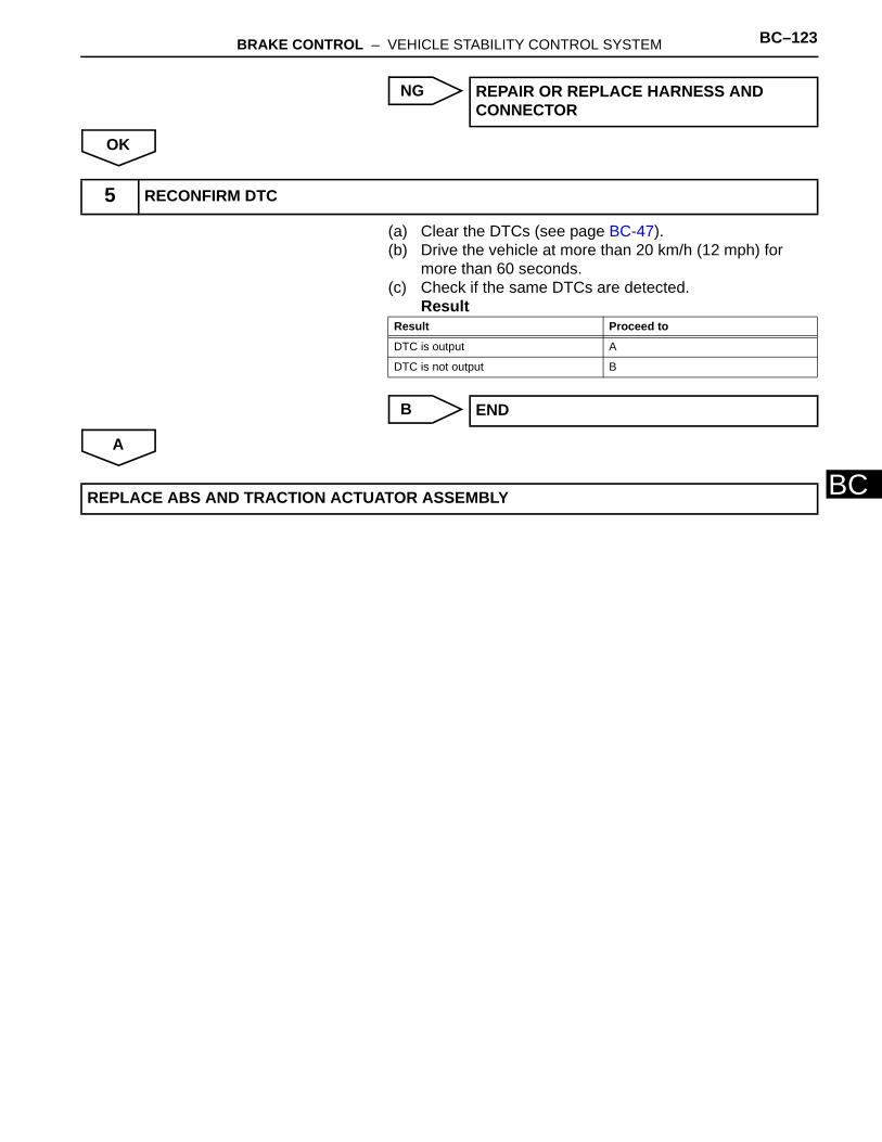
BRAKE CONTROL – VEHICLE STABILITY CONTROL SYSTEM BC–123
BC
NG
OK
(a) Clear the DTCs (see page BC-47).(b) Drive the vehicle at more than 20 km/h (12 mph) for
more than 60 seconds.(c) Check if the same DTCs are detected.
Result
B
A
REPAIR OR REPLACE HARNESS AND CONNECTOR
5 RECONFIRM DTC
Result Proceed to
DTC is output A
DTC is not output B
END
REPLACE ABS AND TRACTION ACTUATOR ASSEMBLY
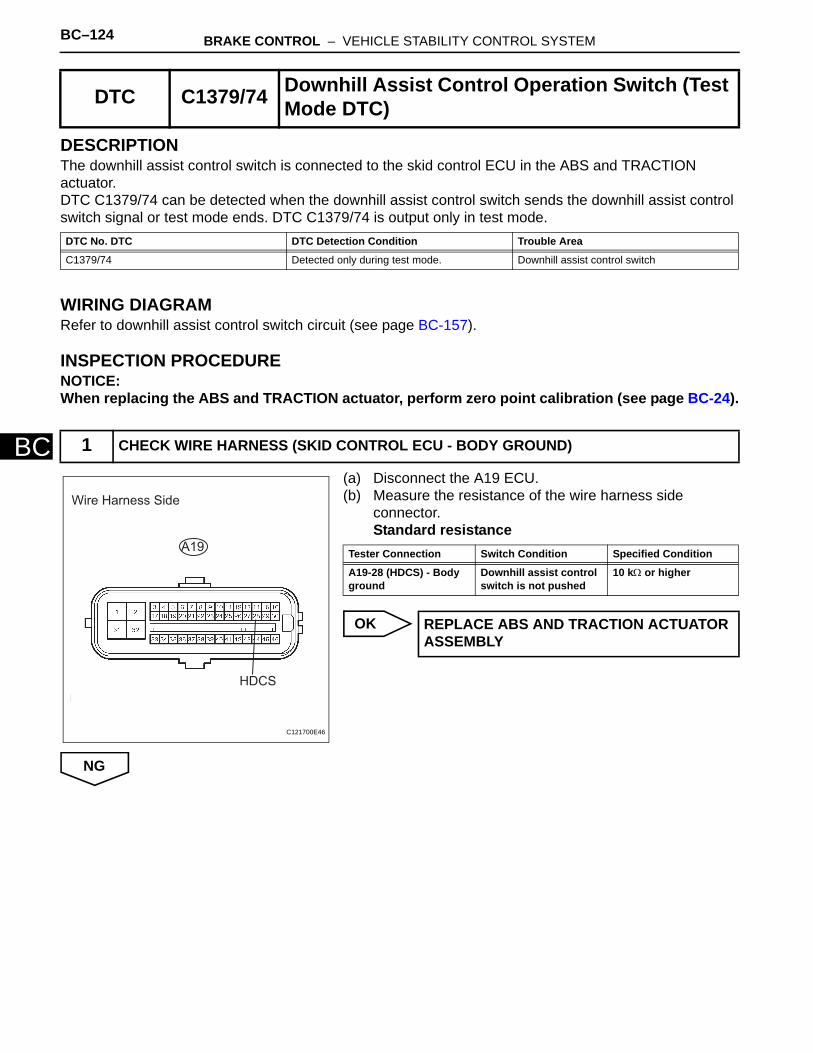
BC–124 BRAKE CONTROL – VEHICLE STABILITY CONTROL SYSTEM
BC
DESCRIPTIONThe downhill assist control switch is connected to the skid control ECU in the ABS and TRACTION actuator.DTC C1379/74 can be detected when the downhill assist control switch sends the downhill assist control switch signal or test mode ends. DTC C1379/74 is output only in test mode.
WIRING DIAGRAMRefer to downhill assist control switch circuit (see page BC-157).
INSPECTION PROCEDURENOTICE:When replacing the ABS and TRACTION actuator, perform zero point calibration (see page BC-24).
(a) Disconnect the A19 ECU.(b) Measure the resistance of the wire harness side
connector.Standard resistance
OK
NG
DTC C1379/74 Downhill Assist Control Operation Switch (Test Mode DTC)
DTC No. DTC DTC Detection Condition Trouble Area
C1379/74 Detected only during test mode. Downhill assist control switch
1 CHECK WIRE HARNESS (SKID CONTROL ECU - BODY GROUND)
Wire Harness Side
A19
HDCS
C121700E46
Tester Connection Switch Condition Specified Condition
A19-28 (HDCS) - Body ground
Downhill assist control switch is not pushed
10 kΩ or higher
REPLACE ABS AND TRACTION ACTUATOR ASSEMBLY
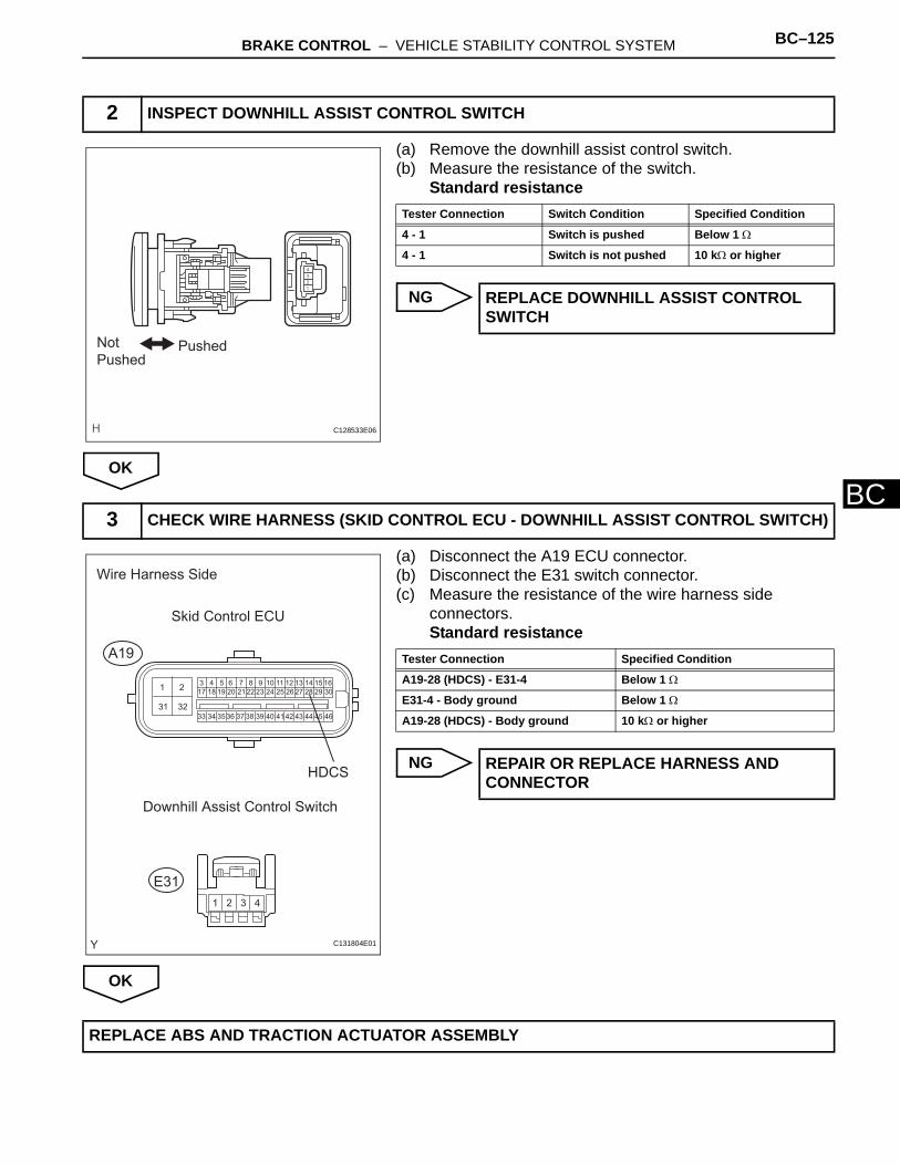
BRAKE CONTROL – VEHICLE STABILITY CONTROL SYSTEM BC–125
BC
(a) Remove the downhill assist control switch.(b) Measure the resistance of the switch.
Standard resistance
NG
OK
(a) Disconnect the A19 ECU connector.(b) Disconnect the E31 switch connector.(c) Measure the resistance of the wire harness side
connectors.Standard resistance
NG
OK
2 INSPECT DOWNHILL ASSIST CONTROL SWITCH
PushedNot
Pushed
C128533E06
Tester Connection Switch Condition Specified Condition
4 - 1 Switch is pushed Below 1 Ω
4 - 1 Switch is not pushed 10 kΩ or higher
REPLACE DOWNHILL ASSIST CONTROL SWITCH
3 CHECK WIRE HARNESS (SKID CONTROL ECU - DOWNHILL ASSIST CONTROL SWITCH)
13 4 5 6 7 8 9 10 11 12 13 14 15 16
17 18 19 20 21 22 23 24 25 26 27 28 29 30
33 34 35 36 37 38 39 40 41 42 43 44 45 46
2
31 32
1 2 3 4
Wire Harness Side
Skid Control ECU
A19
E31
Downhill Assist Control Switch
HDCS
C131804E01
Tester Connection Specified Condition
A19-28 (HDCS) - E31-4 Below 1 Ω
E31-4 - Body ground Below 1 Ω
A19-28 (HDCS) - Body ground 10 kΩ or higher
REPAIR OR REPLACE HARNESS AND CONNECTOR
REPLACE ABS AND TRACTION ACTUATOR ASSEMBLY

BC–126 BRAKE CONTROL – VEHICLE STABILITY CONTROL SYSTEM
BC
DESCRIPTIONThe skid control ECU inputs the stop light switch signal and detects the status of the brake operation.
DTC C1380/64 Stop Light Control Relay Malfunction
DTC No. DTC Detection Condition Trouble Area
C1380/64 When one of following conditions is met:1. When stop light control relay is ON, relay
OFF condition continues for 5 seconds or more.
2. When stop light control relay is OFF, relay ON condition continues for 5 seconds.
3. When stop light control relay is OFF, stop switch monitor (STP2) OFF condition continues for 5 seconds or more.
• Stop light• Stop light switch circuit• Stop light control (BRK) relay• ABS and TRACTION actuator (skid
control ECU)

BRAKE CONTROL – VEHICLE STABILITY CONTROL SYSTEM BC–127
BC
WIRING DIAGRAM
INSPECTION PROCEDURENOTICE:When replacing the ABS and TRACTION actuator, perform zero point calibration (see page BC-24).
Stop Light SwitchSkid Control ECU
STP2
STPO
STOP
STP1
BRK
ECU-IG1
IG1
IG1
AM1
AM1
ALT
FL MAIN
Rear Combination Light LH
Rear Combination Light RH
High Mount Stop Light
Ignition Switch
C132088E01

BC–128 BRAKE CONTROL – VEHICLE STABILITY CONTROL SYSTEM
BC
(a) Check that the light illuminates when the brake pedal is depressed, and turns off when the brake pedal is released.OK
NG
OK
(a) Disconnect the A19 ECU connector.(b) Measure the voltage of the wire harness side connector.
Standard voltage
NG
OK
1 CHECK STOP LIGHT (OPERATION)
Condition Stop Light Condition
Brake pedal depressed Illuminates
Brake pedal released Turn off
Go to step 9
2 CHECK WIRE HARNESS (SKID CONTROL ECU - BATTERY)
Wire Harness Side
A19
STP2
C121700E42
Tester Connection Switch Condition Specified Condition
A19-21 (STP2) - Body ground
Brake pedal depressed 8 to 16 V
A19-21 (STP2) - Body ground
Brake pedal released Below 1.5 V
REPAIR OR REPLACE HARNESS AND CONNECTOR
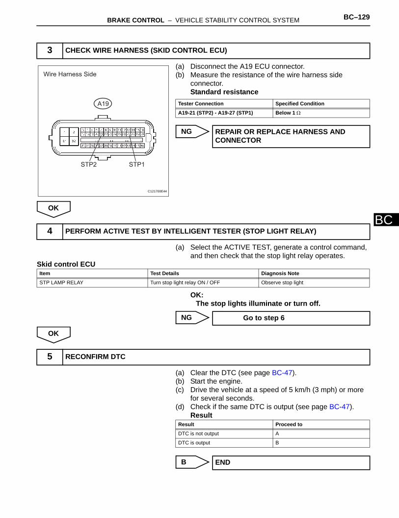
BRAKE CONTROL – VEHICLE STABILITY CONTROL SYSTEM BC–129
BC
(a) Disconnect the A19 ECU connector.(b) Measure the resistance of the wire harness side
connector.Standard resistance
NG
OK
(a) Select the ACTIVE TEST, generate a control command, and then check that the stop light relay operates.
Skid control ECU
OK:The stop lights illuminate or turn off.
NG
OK
(a) Clear the DTC (see page BC-47).(b) Start the engine.(c) Drive the vehicle at a speed of 5 km/h (3 mph) or more
for several seconds.(d) Check if the same DTC is output (see page BC-47).
Result
B
3 CHECK WIRE HARNESS (SKID CONTROL ECU)
Wire Harness Side
A19
STP2 STP1
C121700E44
Tester Connection Specified Condition
A19-21 (STP2) - A19-27 (STP1) Below 1 Ω
REPAIR OR REPLACE HARNESS AND CONNECTOR
4 PERFORM ACTIVE TEST BY INTELLIGENT TESTER (STOP LIGHT RELAY)
Item Test Details Diagnosis Note
STP LAMP RELAY Turn stop light relay ON / OFF Observe stop light
Go to step 6
5 RECONFIRM DTC
Result Proceed to
DTC is not output A
DTC is output B
END

BC–130 BRAKE CONTROL – VEHICLE STABILITY CONTROL SYSTEM
BC
A
(a) Remove the stop light control relay from the engine room No. 1 relay block.
(b) Measure the resistance of the relay.Standard resistance
NG
OK
REPLACE ABS AND TRACTION ACTUATOR ASSEMBLY
6 INSPECT STOP LIGHT CONTROL RELAY (Marking: BRK)
1
1
2
2
3
3
4
4
55
A087121E01
Tester Connection Specified Condition
3 - 4 Below 1 Ω
3 - 5 10 kΩ or higher
3 - 4 10 kΩ or higher(when battery voltage is applied to terminals 1 and 2)
3 - 5 Below 1 Ω(when battery voltage is applied to terminals 1 and 2)
REPLACE STOP LIGHT CONTROL RELAY

BRAKE CONTROL – VEHICLE STABILITY CONTROL SYSTEM BC–131
BC
(a) Remove the stop light control relay.(b) Disconnect the A19 ECU connector.(c) Measure the voltage of the wire harness side connector.
Standard voltage
(d) Measure the resistance of the wire harness side connector.Standard resistance
NG
OK
(a) Clear the DTC (see page BC-47).(b) Start the engine.(c) Drive the vehicle at a speed of 5 km/h (3 mph) or more
for several seconds.(d) Check if the same DTC is output (see page BC-47).
Result
B
A
7 CHECK WIRE HARNESS (ENGINE ROOM NO. 1 RELAY BLOCK - SKID CONTROL ECU AND BATTERY)
Wire Harness Side
Stop Light
Control Realay
Skid Control ECUA19
STPO
Engine Room No. 1 Relay Block
C126306E03
Tester Connection Condition Specified Condition
BRK relay terminal 5 - Body ground
Always 8 to 16 V
BRK relay terminal 2- Body ground
Ignition switch ON 8 to 16 V
Tester Connection Specified Condition
BRK relay terminal 1 - A19-16 (STPO) Below 1 Ω
REPAIR OR REPLACE HARNESS AND CONNECTOR
8 RECONFIRM DTC
Result Proceed to
DTC is not output A
DTC is output B
END
REPLACE ABS AND TRACTION ACTUATOR ASSEMBLY
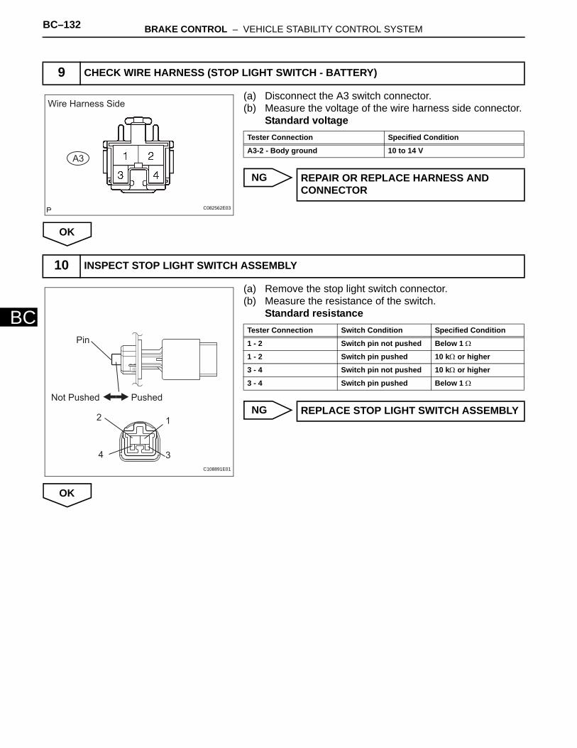
BC–132 BRAKE CONTROL – VEHICLE STABILITY CONTROL SYSTEM
BC
(a) Disconnect the A3 switch connector.(b) Measure the voltage of the wire harness side connector.
Standard voltage
NG
OK
(a) Remove the stop light switch connector.(b) Measure the resistance of the switch.
Standard resistance
NG
OK
9 CHECK WIRE HARNESS (STOP LIGHT SWITCH - BATTERY)
Wire Harness Side
A3
C082562E03
Tester Connection Specified Condition
A3-2 - Body ground 10 to 14 V
REPAIR OR REPLACE HARNESS AND CONNECTOR
10 INSPECT STOP LIGHT SWITCH ASSEMBLY
Pin
Not Pushed Pushed
2 1
34
C108891E01
Tester Connection Switch Condition Specified Condition
1 - 2 Switch pin not pushed Below 1 Ω
1 - 2 Switch pin pushed 10 kΩ or higher
3 - 4 Switch pin not pushed 10 kΩ or higher
3 - 4 Switch pin pushed Below 1 Ω
REPLACE STOP LIGHT SWITCH ASSEMBLY

BRAKE CONTROL – VEHICLE STABILITY CONTROL SYSTEM BC–133
BC
(a) Disconnect the A3 switch connector.(b) Remove the stop light control relay.(c) Measure the resistance of the wire harness side
connectors.Standard resistance
NG
OK
(a) Remove the stop light control relay from the engine room No. 1 relay block.
(b) Measure the resistance of the relay.Standard resistance
NG
OK
11 CHECK WIRE HARNESS (STOP LIGHT SWITCH - STOP LIGHT CONTROL RELAY)
Wire Harness Side
Stop Light
Control Realay
Stop Light Swich
A3
Engine Room No. 1 Relay Block
C126330E02
Tester Connection Specified Condition
A3-1 - BKR relay terminal 4 Below 1 Ω
A3-1 - Body ground 10 kΩ or higher
REPAIR OR REPLACE HARNESS AND CONNECTOR
12 INSPECT STOP LIGHT CONTROL RELAY (Marking: BRK)
1
1
2
2
3
3
4
4
55
A087121E01
Tester Connection Specified Condition
3 - 4 Below 1 Ω
3 - 5 10 kΩ or higher
3 - 4 10 kΩ or higher(when battery voltage is applied to terminals 1 and 2)
3 - 5 Below 1 Ω(when battery voltage is applied to terminals 1 and 2)
REPLACE STOP LIGHT CONTROL RELAY

BC–134 BRAKE CONTROL – VEHICLE STABILITY CONTROL SYSTEM
BC
(a) Disconnect the Q1, K12 and K14 light connectors.(b) Remove the stop light control relay.(c) Measure the resistance of the wire harness side
connectors.Standard resistance
NG
OK
13 CHECK WIRE HARNESS (STOP LIGHT AND REAR COMBINATION LIGHT - CONTROL RELAY)
1 2
Wire Harness Side
Stop Light
Control Realay
Rear Combination Light
K14
K12
High Mount Stop Light
Q1
Engine Room No. 1 Relay Block
C126331E02
Tester Connection Specified Condition
K14-4 - BKR relay terminal 3 Below 1 Ω
K14-4 - Body ground 10 kΩ or higher
K14-1 - Body ground Below 1 Ω
K12-4 - BKR relay terminal 3 Below 1 Ω
K12-4 - Body ground 10 kΩ or higher
K12-1 - Body ground Below 1 Ω
Q1-2 - BKR relay terminal 3 Below 1 Ω
Q1-2 - Body ground 10 kΩ or higher
Q1-1 - Body ground Below 1 Ω
REPAIR OR REPLACE HARNESS AND CONNECTOR
CHECK FOR INTERMITTENT PROBLEMS

BRAKE CONTROL – VEHICLE STABILITY CONTROL SYSTEM BC–135
BC
DESCRIPTION
DTC U0073/94 Control Module Communication Bus OFF
DTC U0100/65 Lost Communication with ECM / PCM
DTC U0123/62 Lost Communication with Yaw Rate Sensor Module
DTC U0124/95 Lost Communication with Lateral Acceleration Sensor Module
DTC U0126/63 Lost Communication with Steering Angle Sen-sor Module
DTC No. DTC Detection Condition Trouble Area
U0073/94
When one of following conditions is met:1. With the IG1 terminal voltage 10 V or more, after
the output of data from the skid control ECU is completed, the sending continues for 5 seconds or more.
2. The condition that bus OFF state occurs once or more within 100 ms occurs 10 times in succession. (Sent signals cannot be received.)
3. With the IG1 terminal voltage 10 V or more, a delay in receiving data from the yaw rate and acceleration sensor and steering angle sensor continues for 1 second or more.
4. With the IG1 terminal voltage 10 V or more, the condition that a delay in receiving data from the yaw rate and acceleration sensor occurs more than once within 5 seconds occurs 10 times in succession.
CAN communication system
U0100/65
When either condition below is met:1. With the IG1 terminal voltage 10 V or more and the
vehicle speed 15 km/h (9 mph) or more, data cannot be sent to the ECM for 2 seconds or more.
2. With the IG1 terminal voltage 10 V or more and the vehicle speed 15 km/h (9 mph) or more for 2 seconds or more.
CAN communication system(Skid control ECU to ECM)
U0123/62
When either condition below is met:1. With the IG1 terminal voltage 10 V or more, data
from the acceleration sensor cannot be received for 1 second or more.
2. With the IG1 terminal voltage 10 V or more, the following occurs 10 times in succession within 60 seconds.(a) The condition that data from the acceleration
sensor cannot be received occurs once or more within 5 seconds.
CAN communication system(Skid control ECU to yaw rate and acceleration sensor)
U0124/95
When either condition below is met:1. With the IG1 terminal voltage 10 V or more, data
from the acceleration sensor cannot be received for 1 second or more.
2. With the IG1 terminal voltage 10 V or more, the following occurs 10 times in succession within 60 seconds.(a) The condition that data from the acceleration
sensor cannot be received occurs once or more within 5 seconds.
CAN communication system(Skid control ECU to yaw rate and acceleration sensor)

BC–136 BRAKE CONTROL – VEHICLE STABILITY CONTROL SYSTEM
BC
INSPECTION PROCEDUREThe skid control ECU inputs the signals from the ECM, steering angle sensor, and yaw rate and acceleration sensor via CAN communication system.
(a) Using the DATA LIST of the intelligent tester, check for any momentary interruption in the wire harness and connector corresponding to a DTC (see page BC-23).
Skid control ECU:
Result
HINT:Perform the above inspection before removing the sensor and connector.
B
C
A
(a) Check if each sensor or ECM connector is securely connected.
OK:The connector should be securely connected.
NG
U0126/63
When either of following conditions detected:1. When IG1 terminal voltage 10 V or more, data from
steering sensor cannot be received for 1 second or more.
2. When IG1 terminal voltage 10 V or more, following condition occurs 10 times in succession.
CAN communication system
1 CHECK HARNESS AND CONNECTOR (MOMENTARY INTERRUPTION)
DTC No. DTC Detection Condition Trouble Area
Item (Display) Measurement Item / Range (Display)
Normal Condition Diagnostic Note
EFI COM OPN EFI communication open detection / ERROR or NORMAL
ERROR: Momentary interruptionNORMAL: Normal
-
STEERING OPN Steering sensor open detection / ERROR or NORMAL
ERROR: Momentary interruptionNORMAL: Normal
-
YAW RATE OPN Yaw rate sensor open detection / ERROR or NORMAL
ERROR: Momentary interruptionNORMAL: Normal
-
Condition Proceed to
There is a constant open circuit A
There are no momentary interruptions
B
There are momentary interruptions C
Go to step 3
Go to step 4
2 CHECK IF EACH SENSOR AND ECM CONNECTOR IS SECURELY CONNECTED
CONNECT CONNECTOR TO EACH SENSOR OR ECM CORRECTLY

BRAKE CONTROL – VEHICLE STABILITY CONTROL SYSTEM BC–137
BC
OK
(a) Record the output DTCs (for ABS, VSC and CAN communication) (see page BC-47).HINT:If the CAN communication system DTC and the relevant sensor DTCs are output simultaneously, troubleshoot the relevant sensor DTCs (for ABS and VSC) after the CAN communication system returns to normal.Result
B
C
A
(a) Repair or replace the harness or connector.(b) Check for any momentary interruption between the skid
control ECU and each sensor or ECM (see page BC-23).(c) Check that there is no momentary interruption.
NEXT
(a) Clear the DTC (see page BC-47).(b) Turn the ignition switch ON.(c) Drive the vehicle and turn the steering wheel to the right
and left at a speed of 15 km/h (9 mph) or more.(d) Check that no CAN communication system DTC is
output (see page BC-47).(e) If ABS and/or VSC DTCs are output, record them.
Result
3 RECONFIRM DTC
Condition Proceed to
DTC (CAN communication system DTC) is not output
A
DTC (ABS and/or VSC DTC) is output B
DTC is not output C
REPAIR CIRCUIT INDICATED BY OUTPUT CODE
USE SIMULATION METHOD TO CHECK
INSPECT CAN COMMUNICATION SYSTEM
4 REPAIR OR REPLACE HARNESS AND CONNECTOR
5 RECONFIRM DTC
Condition Proceed to
DTC for the CAN communication system is not output
A
No DTC is output (ABS and/or VSC DTC are output)
B

BC–138 BRAKE CONTROL – VEHICLE STABILITY CONTROL SYSTEM
BC
HINT:The CAN communication system must be normal when repairing the sensor DTCs (for ABS and VSC).
B
C
A
No DTC is output (No ABS and/or VSC DTC are output)
C
REPAIR CIRCUIT INDICATED BY OUTPUT CODE
END
Condition Proceed to
INSPECT CAN COMMUNICATION SYSTEM
BRAKE CONTROL – VEHICLE STABILITY CONTROL SYSTEM BC–139
BC
DESCRIPTIONIf any of the following conditions are detected, the ABS warning light remains on:1. The ECU connectors are disconnected from the skid control ECU.2. There is a malfunction in the skid control ECU internal circuit.3. There is an open or short in the wire harness between the combination meter and the skid control
ECU.HINT:The intelligent tester may not be used when there is a malfunction in the skid control ECU.
ABS Warning Light Remains ON
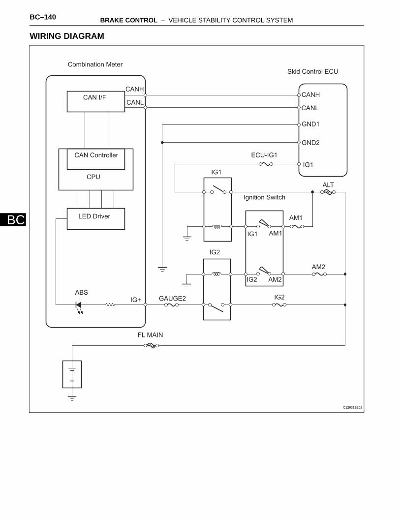
BC–140 BRAKE CONTROL – VEHICLE STABILITY CONTROL SYSTEM
BC
WIRING DIAGRAM
Combination MeterSkid Control ECU
CANH
CANL
CAN I/F
CAN Controller
CPU
LED Driver
ABS
GND1
GND2
IG1
ECU-IG1
IG1
IG2
Ignition Switch
FL MAIN
GAUGE2
AM1
ALT
IG1 AM1
IG2
AM2
AM2IG2
CANH
CANL
IG+
C126319E02

BRAKE CONTROL – VEHICLE STABILITY CONTROL SYSTEM BC–141
BC
INSPECTION PROCEDURE
(a) Check if the CAN communication system DTC is output (see page CA-34).Result
B
A
(a) Check if the skid control ECU connector is properly installed.OK:
The skid control ECU connector is properly installed.
NG
OK
(a) Disconnect the A19 ECU connector.(b) Measure the resistance of the wire harness side
connector.Standard resistance
(c) Measure the voltage of the wire harness side connector.Standard voltage
NG
OK
1 CHECK CAN COMMUNICATION SYSTEM
Result Proceed to
DTC is not output A
DTC is output B
REPAIR CAN COMMUNICATION SYSTEM
2 INSPECT SKID CONTROL ECU CONNECTOR
CONNECT CONNECTOR TO ECU SECURELY
3 CHECK WIRE HARNESS (SKID CONTROL ECU - BATTERY AND BODY GROUND)
Wire Harness Side
A19
GND1
GND2
IG1
C121700E47
Tester Connection Specified Condition
A19-32 (GND1) - Body ground Below 1 Ω
A19-1 (GND2) - Body ground Below 1 Ω
Tester Connection Condition Specified Condition
A19-46 (IG1) - Body ground
Ignition switch ON 10 to 14 V
REPAIR OR REPLACE HARNESS AND CONNECTOR

BC–142 BRAKE CONTROL – VEHICLE STABILITY CONTROL SYSTEM
BC
(a) Select the ACTIVE TEST, generate a control command, and then check that the ABS warning light operates.
Skid control ECU
OK:The ABS warning light is turned on or off.
HINT:When the ABS warning light remains illuminated, opens in the wire harness of the combination meters or abnormalities in the meter circuit should be considered.
NG
OK
4 PERFORM ACTIVE TEST BY INTELLIGENT TESTER (ABS WARNING LIGHT)
Item (Display) Test Details Diagnostic Note
ABS WARN LAMP Turns ABS warning light / ON or OFF Observe combination meter
CHECK METER / GAUGE SYSTEM
REPLACE ABS AND TRACTION ACTUATOR ASSEMBLY
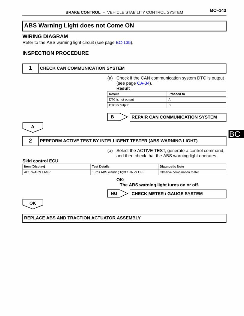
BRAKE CONTROL – VEHICLE STABILITY CONTROL SYSTEM BC–143
BC
WIRING DIAGRAMRefer to the ABS warning light circuit (see page BC-135).
INSPECTION PROCEDURE
(a) Check if the CAN communication system DTC is output (see page CA-34).Result
B
A
(a) Select the ACTIVE TEST, generate a control command, and then check that the ABS warning light operates.
Skid control ECU
OK:The ABS warning light turns on or off.
NG
OK
ABS Warning Light does not Come ON
1 CHECK CAN COMMUNICATION SYSTEM
Result Proceed to
DTC is not output A
DTC is output B
REPAIR CAN COMMUNICATION SYSTEM
2 PERFORM ACTIVE TEST BY INTELLIGENT TESTER (ABS WARNING LIGHT)
Item (Display) Test Details Diagnostic Note
ABS WARN LAMP Turns ABS warning light / ON or OFF Observe combination meter
CHECK METER / GAUGE SYSTEM
REPLACE ABS AND TRACTION ACTUATOR ASSEMBLY

BC–144 BRAKE CONTROL – VEHICLE STABILITY CONTROL SYSTEM
BC
DESCRIPTIONThe skid control ECU is connected to the combination meter via the CAN communication system.w/o Multi information display:If the skid control ECU stores any DTCs which relate to the VSC system, the VSC warning light comes on in the combination meter.w/ Multi information display:If the skid control ECU stores any DTCs which relate to the VSC system, the master caution indicator light comes on and the warning message is displayed on the multi information display in the combination meter.
VSC Warning Light Remains ON

BRAKE CONTROL – VEHICLE STABILITY CONTROL SYSTEM BC–145
BC
WIRING DIAGRAM
INSPECTION PROCEDURENOTICE:When replacing the ABS and TRACTION actuator, perform the zero point calibration (see page BC-24).
Combination MeterSkid Control ECU
CANH
CANL
CAN I/F
CAN Controller
CPU
LED Driver
VSC
GND1
GND2
IG1
ECU-IG1
IG1
IG2
Ignition Switch
FL MAIN
GAUGE2
AM1
ALT
IG1 AM1
IG2
AM2
AM2IG2
CANH
CANL
IG+
C126319E03

BC–146 BRAKE CONTROL – VEHICLE STABILITY CONTROL SYSTEM
BC
(a) Check if the CAN communication system DTC is output (see page BC-47).Result
NG
OK
(a) Check if the skid control ECU connector is securely connected. OK:
The connector is securely connected.
NG
OK
(a) Check the combination meter (see page ME-15).
NG
OK
1 CHECK CAN COMMUNICATION SYSTEM
Result Proceed to
DTC is not output A
DTC is output B
REPAIR CAN COMMUNICATION SYSTEM
2 INSPECT SKID CONTROL ECU CONNECTOR
CONNECT CONNECTOR CORRECTLY
3 CHECK COMBINATION METER ASSEMBLY
REPLACE COMBINATION METER ASSEMBLY
REPLACE ABS AND TRACTION ACTUATOR ASSEMBLY
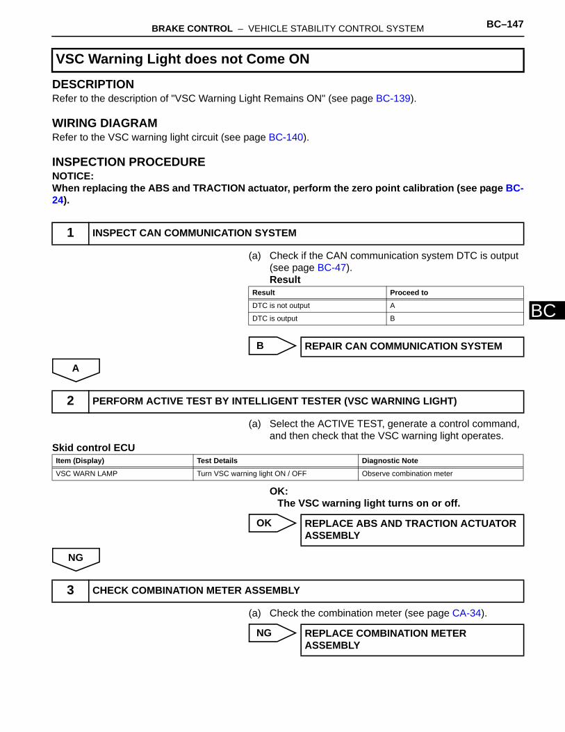
BRAKE CONTROL – VEHICLE STABILITY CONTROL SYSTEM BC–147
BC
DESCRIPTIONRefer to the description of "VSC Warning Light Remains ON" (see page BC-139).
WIRING DIAGRAMRefer to the VSC warning light circuit (see page BC-140).
INSPECTION PROCEDURENOTICE:When replacing the ABS and TRACTION actuator, perform the zero point calibration (see page BC-24).
(a) Check if the CAN communication system DTC is output (see page BC-47). Result
B
A
(a) Select the ACTIVE TEST, generate a control command, and then check that the VSC warning light operates.
Skid control ECU
OK:The VSC warning light turns on or off.
OK
NG
(a) Check the combination meter (see page CA-34).
NG
VSC Warning Light does not Come ON
1 INSPECT CAN COMMUNICATION SYSTEM
Result Proceed to
DTC is not output A
DTC is output B
REPAIR CAN COMMUNICATION SYSTEM
2 PERFORM ACTIVE TEST BY INTELLIGENT TESTER (VSC WARNING LIGHT)
Item (Display) Test Details Diagnostic Note
VSC WARN LAMP Turn VSC warning light ON / OFF Observe combination meter
REPLACE ABS AND TRACTION ACTUATOR ASSEMBLY
3 CHECK COMBINATION METER ASSEMBLY
REPLACE COMBINATION METER ASSEMBLY

BC–148 BRAKE CONTROL – VEHICLE STABILITY CONTROL SYSTEM
BC
OK
REPLACE ABS AND TRACTION ACTUATOR ASSEMBLY

BRAKE CONTROL – VEHICLE STABILITY CONTROL SYSTEM BC–149
BC
DESCRIPTIONIf any of the following conditions are detected, the brake warning light remains on:1. The ECU connectors are disconnected from the skid control ECU.2. The brake fluid level is insufficient.3. The parking brake is applied.4. The EBD is defective.
Brake Warning Light Remains ON

BC–150 BRAKE CONTROL – VEHICLE STABILITY CONTROL SYSTEM
BC
WIRING DIAGRAM
Combination MeterSkid Control ECU
CANH
CANLInstrument Panel Junction Block
(Main Body ECU)
Parking Brake Switch
Assembly
CAN I/F
CAN Controller
CPU
LED Driver
BRAKE
Brake Fluid Level
Warning Switch
CANH
CANL
GND1
GND2
IG1ECU-IG1
IG1
IG2
Ignition Switch
FL MAIN
GAUGE2
PKB
AM1
ALT
IG1 AM1
IG2
AM2
AM2IG2
CANH
CANL
IG+
SW
C126320E02
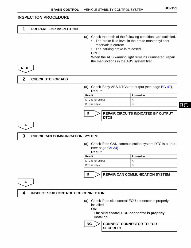
BRAKE CONTROL – VEHICLE STABILITY CONTROL SYSTEM BC–151
BC
INSPECTION PROCEDURE
(a) Check that both of the following conditions are satisfied.• The brake fluid level in the brake master cylinder
reservoir is correct.• The parking brake is released.HINT:When the ABS warning light remains illuminated, repair the malfunctions in the ABS system first.
NEXT
(a) Check if any ABS DTCs are output (see page BC-47).Result
B
A
(a) Check if the CAN communication system DTC is output (see page CA-34).Result
B
A
(a) Check if the skid control ECU connector is properly installed. OK:
The skid control ECU connector is properly installed.
NG
1 PREPARE FOR INSPECTION
2 CHECK DTC FOR ABS
Result Proceed to
DTC is not output A
DTC is output B
REPAIR CIRCUITS INDICATED BY OUTPUT DTCS
3 CHECK CAN COMMUNICATION SYSTEM
Result Proceed to
DTC is not output A
DTC is output B
REPAIR CAN COMMUNICATION SYSTEM
4 INSPECT SKID CONTROL ECU CONNECTOR
CONNECT CONNECTOR TO ECU SECURELY

BC–152 BRAKE CONTROL – VEHICLE STABILITY CONTROL SYSTEM
BC
OK
(a) Disconnect the A19 ECU connector.(b) Measure the resistance of the wire harness side
connector.Standard resistance
(c) Measure the voltage of the wire harness side connector.Standard voltage
NG
OK
(a) Using the DATA LIST, check for proper functioning of the parking brake switch.
Skid control ECU
OK:When the parking brake lever is operated, the display changes as shown above.
NG
OK
5 CHECK WIRE HARNESS (SKID CONTROL ECU - BATTERY AND BODY GROUND)
Wire Harness Side
A19
GND1
GND2
IG1
C121700E47
Tester Connection Specified Condition
A19-32 (GND1) - Body ground Below 1 Ω
A19-1 (GND2) - Body ground Below 1 Ω
Tester Connection Condition Specified Condition
A19-46 (IG1) - Body ground
Ignition switch ON 10 to 14 V
REPAIR OR REPLACE HARNESS AND CONNECTOR
6 READ VALUE OF INTELLIGENT TESTER (PARKING BRAKE SWITCH)
Item (Display) Measurement Item / Range (Display)
Normal Condition Diagnostic Note
PARKING BRAKE SW Parking brake switch / ON or OFF ON: Parking brake appliedOFF: Parking brake released
-
Go to step 10
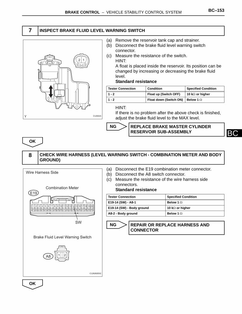
BRAKE CONTROL – VEHICLE STABILITY CONTROL SYSTEM BC–153
BC
(a) Remove the reservoir tank cap and strainer.(b) Disconnect the brake fluid level warning switch
connector.(c) Measure the resistance of the switch.
HINT:A float is placed inside the reservoir. Its position can be changed by increasing or decreasing the brake fluid level.Standard resistance
HINT:If there is no problem after the above check is finished, adjust the brake fluid level to the MAX level.
NG
OK
(a) Disconnect the E19 combination meter connector.(b) Disconnect the A8 switch connector.(c) Measure the resistance of the wire harness side
connectors.Standard resistance
NG
OK
7 INSPECT BRAKE FLUID LEVEL WARNING SWITCH
12
C126315
Tester Connection Condition Specified Condition
1 - 2 Float up (Switch OFF) 10 kΩ or higher
1 - 2 Float down (Switch ON) Below 1 Ω
REPLACE BRAKE MASTER CYLINDER RESERVOIR SUB-ASSEMBLY
8 CHECK WIRE HARNESS (LEVEL WARNING SWITCH - COMBINATION METER AND BODY GROUND)
1 2
Wire Harness Side
Combination Meter
E19
A8
SW
Brake Fluid Level Warning Switch
C126282E02
Tester Connection Specified Condition
E19-14 (SW) - A8-1 Below 1 Ω
E19-14 (SW) - Body ground 10 kΩ or higher
A8-2 - Body ground Below 1 Ω
REPAIR OR REPLACE HARNESS AND CONNECTOR
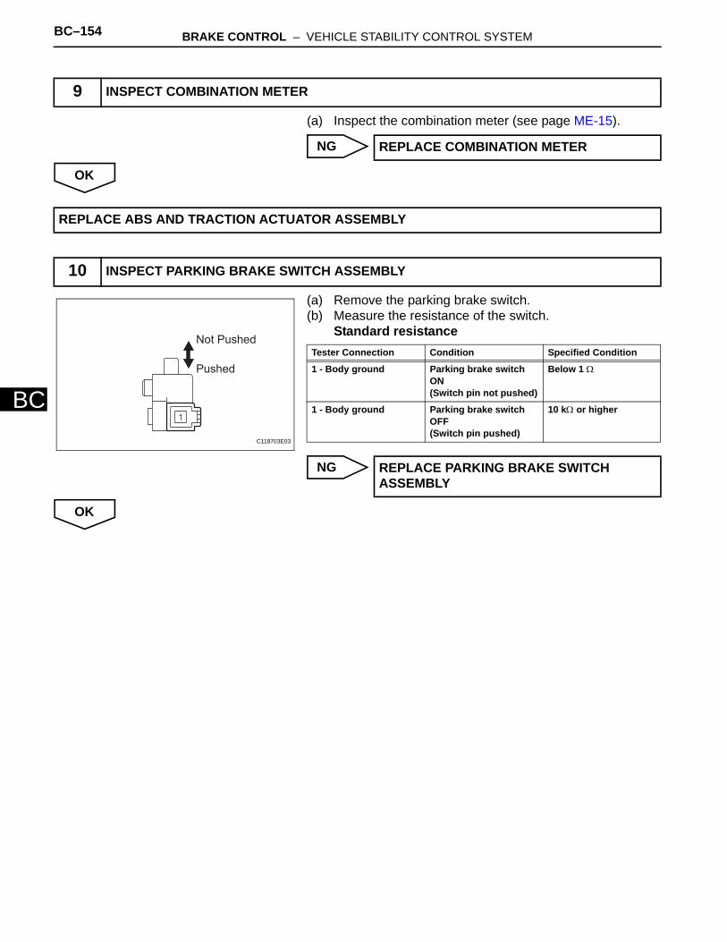
BC–154 BRAKE CONTROL – VEHICLE STABILITY CONTROL SYSTEM
BC
(a) Inspect the combination meter (see page ME-15).
NG
OK
(a) Remove the parking brake switch.(b) Measure the resistance of the switch.
Standard resistance
NG
OK
9 INSPECT COMBINATION METER
REPLACE COMBINATION METER
REPLACE ABS AND TRACTION ACTUATOR ASSEMBLY
10 INSPECT PARKING BRAKE SWITCH ASSEMBLY
Not Pushed
Pushed
C118703E03
Tester Connection Condition Specified Condition
1 - Body ground Parking brake switch ON(Switch pin not pushed)
Below 1 Ω
1 - Body ground Parking brake switch OFF(Switch pin pushed)
10 kΩ or higher
REPLACE PARKING BRAKE SWITCH ASSEMBLY

BRAKE CONTROL – VEHICLE STABILITY CONTROL SYSTEM BC–155
BC
(a) Disconnect the 1D junction block connector.(b) Disconnect the E41 switch connector.(c) Measure the resistance of the wire harness side
connectors.Standard resistance
NG
OK
11 CHECK WIRE HARNESS (JUNCTION BLOCK - PARKING BRAKE SWITCH AND BODY GROUND)
1
Wire Harness Side
Instrument Panel Junction Block
(Main Body ECU)
Parking Brake Switch
E41
1D
PKB
C126283E02
Tester Connection Specified Condition
1D-4 (PKB) - E41-1 Below 1 Ω
1D-4 (PKB) - Body ground 10 kΩ or higher
REPAIR OR REPLACE HARNESS AND CONNECTOR
REPLACE INSTRUMENT PANEL JUNCTION BLOCK
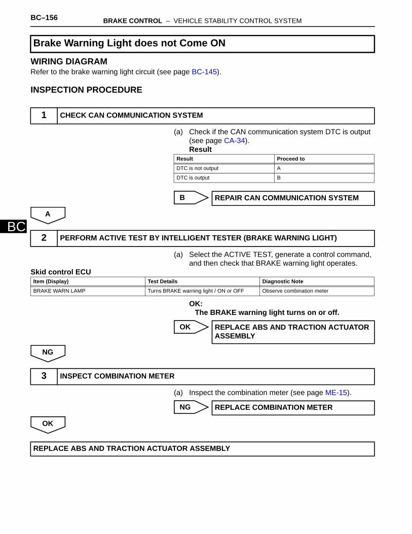
BC–156 BRAKE CONTROL – VEHICLE STABILITY CONTROL SYSTEM
BC
WIRING DIAGRAMRefer to the brake warning light circuit (see page BC-145).
INSPECTION PROCEDURE
(a) Check if the CAN communication system DTC is output (see page CA-34).Result
B
A
(a) Select the ACTIVE TEST, generate a control command, and then check that BRAKE warning light operates.
Skid control ECU
OK:The BRAKE warning light turns on or off.
OK
NG
(a) Inspect the combination meter (see page ME-15).
NG
OK
Brake Warning Light does not Come ON
1 CHECK CAN COMMUNICATION SYSTEM
Result Proceed to
DTC is not output A
DTC is output B
REPAIR CAN COMMUNICATION SYSTEM
2 PERFORM ACTIVE TEST BY INTELLIGENT TESTER (BRAKE WARNING LIGHT)
Item (Display) Test Details Diagnostic Note
BRAKE WARN LAMP Turns BRAKE warning light / ON or OFF Observe combination meter
REPLACE ABS AND TRACTION ACTUATOR ASSEMBLY
3 INSPECT COMBINATION METER
REPLACE COMBINATION METER
REPLACE ABS AND TRACTION ACTUATOR ASSEMBLY

BRAKE CONTROL – VEHICLE STABILITY CONTROL SYSTEM BC–157
BC
DESCRIPTIONThe slip indicator blinks during VSC and/or TRC operation.When the system fails, the slip indicator comes on to warn the driver.For 2WD: With Auto LSD switch ON, when the hydraulic brake booster is at a high temperature, the slip indicator illuminates.
WIRING DIAGRAM
Slip Indicator Light Remains ON
Skid Control ECU
Combination Meter
CAN I/F CANH
CANL
CAN Controller
CPU
IG2
IG2
AM2
LED Driver
SLIP GAUGE2
FL MAIN
Ignition Switch
AM2IG2
IG+
CANH
CANL
C126300E03

BC–158 BRAKE CONTROL – VEHICLE STABILITY CONTROL SYSTEM
BC
INSPECTION PROCEDURENOTICE:When replacing the ABS and TRACTION actuator, perform the zero point calibration (see page BC-24).
(a) Check if the CAN communication system DTC is output (see page CA-34). Result
B
A
(a) Check if the skid control ECU connector is securely connected. OK:
The connector is securely connected.
NG
OK
(a) Check the combination meter (see page ME-15).
NG
OK
1 CHECK CAN COMMUNICATION SYSTEM
Result Proceed to
DTC is not output A
DTC is output B
REPAIR CAN COMMUNICATION SYSTEM
2 CHECK SKID CONTROL ECU CONNECTOR
CONNECT CONNECTOR CORRECTLY
3 CHECK COMBINATION METER
REPLACE COMBINATION METER
REPLACE ABS AND TRACTION ACTUATOR ASSEMBLY

BRAKE CONTROL – VEHICLE STABILITY CONTROL SYSTEM BC–159
BC
DESCRIPTIONRefer to the description of "Slip Indicator Light Remains ON" (see page BC-152).
WIRING DIAGRAMRefer to the SLIP indicator light circuit (see page BC-152).
INSPECTION PROCEDURENOTICE:When replacing the ABS and TRACTION actuator, perform the zero point calibration (see page BC-24).
(a) Check if the CAN communication system DTC is output (see page CA-34). Result
B
A
(a) Using the intelligent tester's ACTIVE TEST, generate a control command, and then check that the SLIP indicator light operates.
Skid control ECU
OK:The SLIP indicator light turns ON and OFF.
NG
OK
(a) Inspect the combination meter (see page ME-15).
NG
Slip Indicator Light does not Come ON
1 CHECK CAN COMMUNICATION SYSTEM
Result Proceed to
DTC is not output A
DTC is output B
REPAIR CAN COMMUNICATION SYSTEM
2 PERFORM ACTIVE TEST BY INTELLIGENT TESTER (SLIP INDICATOR LIGHT)
Item (Display) Test Details Diagnostic Note
SLIP INDI LAMP Turn slip indicator light ON / OFF Observe combination meter
Go to step 3
REPLACE ABS AND TRACTION ACTUATOR ASSEMBLY
3 CHECK COMBINATION METER
REPLACE COMBINATION METER
BC–160 BRAKE CONTROL – VEHICLE STABILITY CONTROL SYSTEM
BC
OK
REPLACE ABS AND TRACTION ACTUATOR ASSEMBLY

BRAKE CONTROL – VEHICLE STABILITY CONTROL SYSTEM BC–161
BC
DESCRIPTIONWhen the downhill assist control switch is pushed on, the downhill assist control function is available and the downhill assist control indicator light illuminates.HINT:Even if the downhill assist control switch is pressed, the downhill assist control indicator light will blink and downhill assist control will not be activated under the following conditions:• Gear position is not L or R.• The system is malfunctioning.• Temperature of the hydraulic brake booster increases and downhill assist control is temporarily
canceled.• The vehicle speed is 25 km/h (15 mph) or more.
Downhill Assist Control Indicator Light Remains ON

BC–162 BRAKE CONTROL – VEHICLE STABILITY CONTROL SYSTEM
BC
WIRING DIAGRAM
Combination Meter
CAN I/F
CAN Controller
CPU
LED Driver
Downhill assist Control
GAUGE2
IG2
Ignition Switch
AM2 IG2
AM2-2FL MAIN
IG2
HDCS
Downhill Assist
Control Switch
CANH
CANL
Skid Control ECU
CANH
CANL
IG+
C126314E06
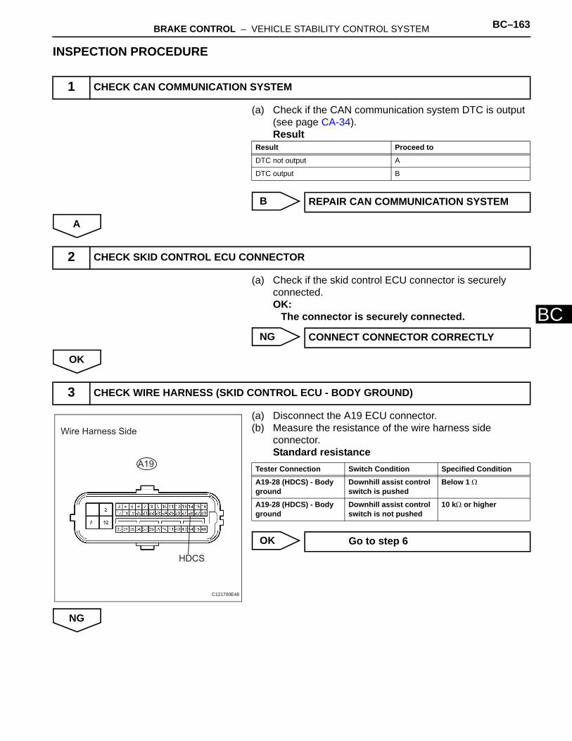
BRAKE CONTROL – VEHICLE STABILITY CONTROL SYSTEM BC–163
BC
INSPECTION PROCEDURE
(a) Check if the CAN communication system DTC is output (see page CA-34).Result
B
A
(a) Check if the skid control ECU connector is securely connected.OK:
The connector is securely connected.
NG
OK
(a) Disconnect the A19 ECU connector.(b) Measure the resistance of the wire harness side
connector.Standard resistance
OK
NG
1 CHECK CAN COMMUNICATION SYSTEM
Result Proceed to
DTC not output A
DTC output B
REPAIR CAN COMMUNICATION SYSTEM
2 CHECK SKID CONTROL ECU CONNECTOR
CONNECT CONNECTOR CORRECTLY
3 CHECK WIRE HARNESS (SKID CONTROL ECU - BODY GROUND)
Wire Harness Side
A19
HDCS
C121700E48
Tester Connection Switch Condition Specified Condition
A19-28 (HDCS) - Body ground
Downhill assist control switch is pushed
Below 1 Ω
A19-28 (HDCS) - Body ground
Downhill assist control switch is not pushed
10 kΩ or higher
Go to step 6
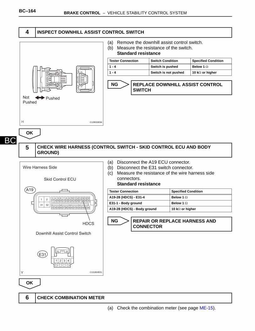
BC–164 BRAKE CONTROL – VEHICLE STABILITY CONTROL SYSTEM
BC
(a) Remove the downhill assist control switch.(b) Measure the resistance of the switch.
Standard resistance
NG
OK
(a) Disconnect the A19 ECU connector.(b) Disconnect the E31 switch connector.(c) Measure the resistance of the wire harness side
connectors.Standard resistance
NG
OK
(a) Check the combination meter (see page ME-15).
4 INSPECT DOWNHILL ASSIST CONTROL SWITCH
PushedNot
Pushed
C128533E06
Tester Connection Switch Condition Specified Condition
1 - 4 Switch is pushed Below 1 Ω
1 - 4 Switch is not pushed 10 kΩ or higher
REPLACE DOWNHILL ASSIST CONTROL SWITCH
5 CHECK WIRE HARNESS (CONTROL SWITCH - SKID CONTROL ECU AND BODY GROUND)
13 4 5 6 7 8 9 10 11 12 13 14 15 16
17 18 19 20 21 22 23 24 25 26 27 28 29 30
33 34 35 36 37 38 39 40 41 42 43 44 45 46
2
31 32
1 2 3 4
Wire Harness Side
Skid Control ECU
A19
E31
Downhill Assist Control Switch
HDCS
C131804E01
Tester Connection Specified Condition
A19-28 (HDCS) - E31-4 Below 1 Ω
E31-1 - Body ground Below 1 Ω
A19-28 (HDCS) - Body ground 10 kΩ or higher
REPAIR OR REPLACE HARNESS AND CONNECTOR
6 CHECK COMBINATION METER

BRAKE CONTROL – VEHICLE STABILITY CONTROL SYSTEM BC–165
BC
NG
OK
REPLACE COMBINATION METER
REPLACE ABS AND TRACTION ACTUATOR ASSEMBLY

BC–166 BRAKE CONTROL – VEHICLE STABILITY CONTROL SYSTEM
BC
DESCRIPTIONRefer to the description of "Downhill Assist Control Indicator Light Remains ON" (see page BC-156).
WIRING DIAGRAMRefer to the downhill assist control indicator light circuit (see page BC-157).
INSPECTION PROCEDURE
(a) Check if the CAN communication system DTC is output (see page CA-34)
Result
B
A
(a) Check the DATA LIST for proper functioning of the downhill assist control switch.
Skid control ECU
OK:ON (downhill assist control switch is ON) appears on the screen.
NG
OK
(a) Select the ACTIVE TEST, generate a control command, and then check that the downhill assist control indicator light operates.
Skid control ECU
Downhill Assist Control Indicator Light does not Come ON
1 CHECK CAN COMMUNICATION SYSTEM
Result Proceed to
DTC is not output A
DTC is output B
REPAIR CAN COMMUNICATION SYSTEM
2 READ VALUE OF INTELLIGENT TESTER (DOWNHILL ASSIST CONTROL SWITCH)
Item (Display) Measurement Item / Range (Display)
Normal Condition Diagnostic Note
Downhill assist control SW Downhill assist control switch / ON or OFF
ON: Downhill assist control switch is ONOFF: Downhill assist control switch is OFF
-
Go to step 5
3 PERFORM ACTIVE TEST BY INTELLIGENT TESTER (DAC INDICATOR LIGHT)
Item (Display) Test Details Diagnostic Note
Downhill assist control INDI LAMP Turn downhill assist control indicator light ON / OFF
Observe combination meter
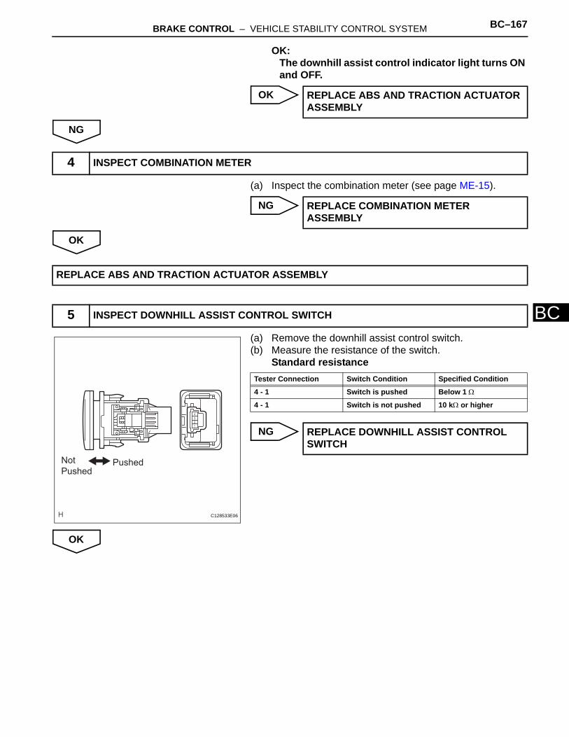
BRAKE CONTROL – VEHICLE STABILITY CONTROL SYSTEM BC–167
BC
OK:The downhill assist control indicator light turns ON and OFF.
OK
NG
(a) Inspect the combination meter (see page ME-15).
NG
OK
(a) Remove the downhill assist control switch.(b) Measure the resistance of the switch.
Standard resistance
NG
OK
REPLACE ABS AND TRACTION ACTUATOR ASSEMBLY
4 INSPECT COMBINATION METER
REPLACE COMBINATION METER ASSEMBLY
REPLACE ABS AND TRACTION ACTUATOR ASSEMBLY
5 INSPECT DOWNHILL ASSIST CONTROL SWITCH
PushedNot
Pushed
C128533E06
Tester Connection Switch Condition Specified Condition
4 - 1 Switch is pushed Below 1 Ω
4 - 1 Switch is not pushed 10 kΩ or higher
REPLACE DOWNHILL ASSIST CONTROL SWITCH
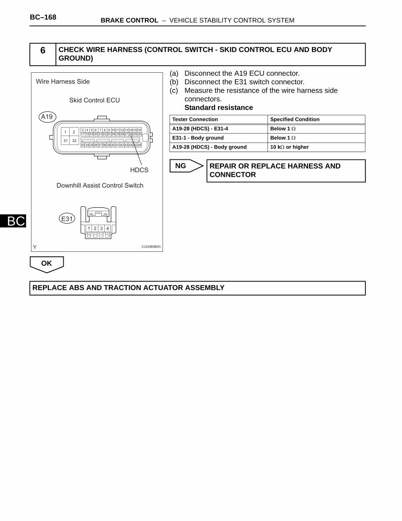
BC–168 BRAKE CONTROL – VEHICLE STABILITY CONTROL SYSTEM
BC
(a) Disconnect the A19 ECU connector.(b) Disconnect the E31 switch connector.(c) Measure the resistance of the wire harness side
connectors.Standard resistance
NG
OK
6 CHECK WIRE HARNESS (CONTROL SWITCH - SKID CONTROL ECU AND BODY GROUND)
13 4 5 6 7 8 9 10 11 12 13 14 15 16
17 18 19 20 21 22 23 24 25 26 27 28 29 30
33 34 35 36 37 38 39 40 41 42 43 44 45 46
2
31 32
1 2 3 4
Wire Harness Side
Skid Control ECU
A19
E31
Downhill Assist Control Switch
HDCS
C131804E01
Tester Connection Specified Condition
A19-28 (HDCS) - E31-4 Below 1 Ω
E31-1 - Body ground Below 1 Ω
A19-28 (HDCS) - Body ground 10 kΩ or higher
REPAIR OR REPLACE HARNESS AND CONNECTOR
REPLACE ABS AND TRACTION ACTUATOR ASSEMBLY
BRAKE CONTROL – VEHICLE STABILITY CONTROL SYSTEM BC–169
BC
DESCRIPTIONThis is the auto LSD switch for 2WD. When the auto LSD switch is pushed on, the auto LSD function is available and the auto LSD indicator light illuminates.HINT:The auto LSD does not operate even if the auto LSD switch is pressed under the following conditions:• The TRC or VSC system is faulty.• The temperature inside the hydraulic brake booster increases and the auto LSD operation is
suspended.
AUTO LSD Indicator Light Remains ON
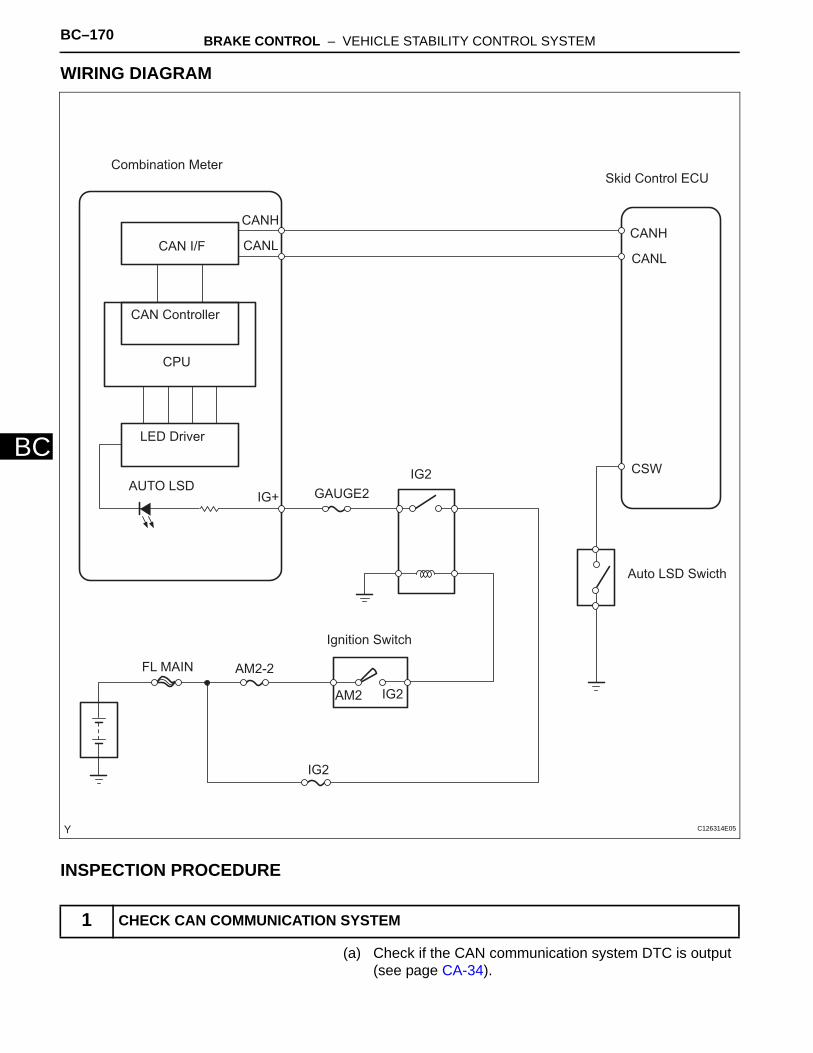
BC–170 BRAKE CONTROL – VEHICLE STABILITY CONTROL SYSTEM
BC
WIRING DIAGRAM
INSPECTION PROCEDURE
(a) Check if the CAN communication system DTC is output (see page CA-34).
1 CHECK CAN COMMUNICATION SYSTEM
Combination Meter
CAN I/F
CAN Controller
CPU
LED Driver
AUTO LSD GAUGE2IG2
Ignition Switch
AM2 IG2
AM2-2FL MAIN
IG2
CSW
Auto LSD Swicth
CANH
CANL
Skid Control ECU
CANH
CANL
IG+
C126314E05
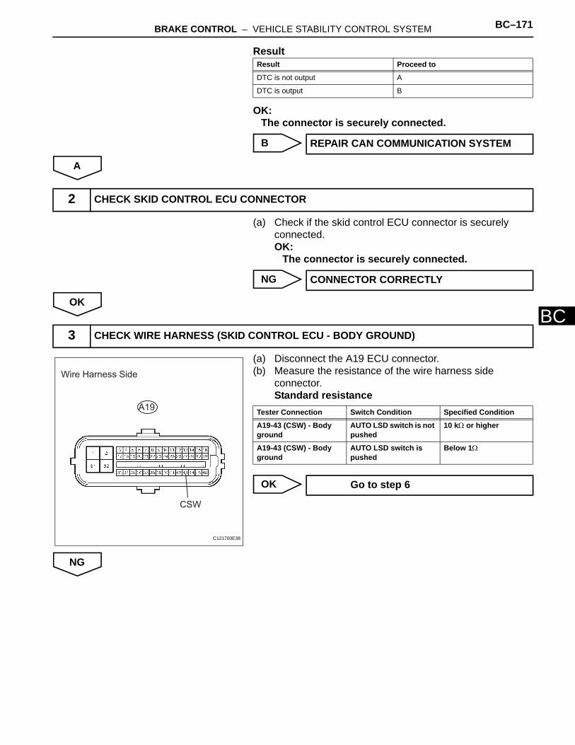
BRAKE CONTROL – VEHICLE STABILITY CONTROL SYSTEM BC–171
BC
Result
OK:The connector is securely connected.
B
A
(a) Check if the skid control ECU connector is securely connected.OK:
The connector is securely connected.
NG
OK
(a) Disconnect the A19 ECU connector.(b) Measure the resistance of the wire harness side
connector.Standard resistance
OK
NG
Result Proceed to
DTC is not output A
DTC is output B
REPAIR CAN COMMUNICATION SYSTEM
2 CHECK SKID CONTROL ECU CONNECTOR
CONNECTOR CORRECTLY
3 CHECK WIRE HARNESS (SKID CONTROL ECU - BODY GROUND)
Wire Harness Side
A19
CSW
C121700E38
Tester Connection Switch Condition Specified Condition
A19-43 (CSW) - Body ground
AUTO LSD switch is not pushed
10 kΩ or higher
A19-43 (CSW) - Body ground
AUTO LSD switch is pushed
Below 1Ω
Go to step 6
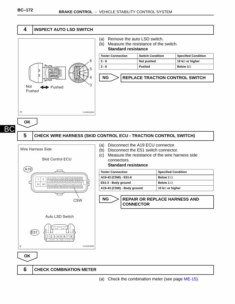
BC–172 BRAKE CONTROL – VEHICLE STABILITY CONTROL SYSTEM
BC
(a) Remove the auto LSD switch.(b) Measure the resistance of the switch.
Standard resistance
NG
OK
(a) Disconnect the A19 ECU connector.(b) Disconnect the E51 switch connector.(c) Measure the resistance of the wire harness side
connectors.Standard resistance
NG
OK
(a) Check the combination meter (see page ME-15).
4 INSPECT AUTO LSD SWITCH
Not Pushed
Pushed
6
5
4
3
C128532E02
Tester Connection Switch Condition Specified Condition
3 - 6 Not pushed 10 kΩ or higher
3 - 6 Pushed Below 1Ω
REPLACE TRACTION CONTROL SWITCH
5 CHECK WIRE HARNESS (SKID CONTROL ECU - TRACTION CONTROL SWITCH)
1 3 4 5 6 7 8 9 10 11 12 13 14 15 1617 18 19 20 21 22 23 24 25 26 27 28 29 30
33 34 35 36 37 38 39 40 41 42 43 44 45 46
2
31 32
1 2 3 4 5 6 7 8
Wire Harness Side
Skid Control ECU
A19
E51
Auto LSD Switch
CSW
C131915E02
Tester Connection Specified Condition
A19-43 (CSW) - E51-6 Below 1 Ω
E51-3 - Body ground Below 1 Ω
A19-43 (CSW) - Body ground 10 kΩ or higher
REPAIR OR REPLACE HARNESS AND CONNECTOR
6 CHECK COMBINATION METER
BRAKE CONTROL – VEHICLE STABILITY CONTROL SYSTEM BC–173
BC
NG
OK
REPLACE COMBINATION METER ASSEMBLY
REPLACE ABS AND TRACTION ACTUATOR ASSEMBLY

BC–174 BRAKE CONTROL – VEHICLE STABILITY CONTROL SYSTEM
BC
DESCRIPTIONRefer to the description of "AUTO LSD Indicator Light Remains ON" (see page BC-164).
WIRING DIAGRAMRefer to the AUTO LSD indicator light circuit (see page BC-165).
INSPECTION PROCEDURE
(a) Check if the CAN communication system DTC is output (see page CA-34).
Result
B
A
(a) Check the Data List for proper functioning of the Auto LSD switch.
Skid control ECU
OK:ON (downhill assist control switch is ON) appears on the screen.
NG
OK
(a) Select the ACTIVE TEST, generate a control command, and then check that the AUTO LSD indicator light operates.
Skid control ECU
OK:The AUTO LSD indicator light turns ON and OFF.
AUTO LSD Indicator Light does not Come ON
1 CHECK CAN COMMUNICATION SYSTEM
Result Proceed to
DTC is not output A
DTC is output B
REPAIR CAN COMMUNICATION SYSTEM
2 READ VALUE OF INTELLIGENT TESTER (AUTO LSD SWITCH)
Item (Display) Measurement Item / Range (Display)
Normal Condition Diagnostic Note
AUTO LSD SW Auto LSD switch (AUTO LSD switch) / ON or OFF
ON: Auto LSD switch is ONOFF: Auto LSD switch is OFF
-
Go to step 5
3 PERFORM ACTIVE TEST BY INTELLIGENT TESTER (AUTO LSD INDICATOR LIGHT)
Item (Display) Test Details Diagnostic Note
AUTO LSD LAMP Turn AUTO LSD indicator light ON / OFF Observe combination meter
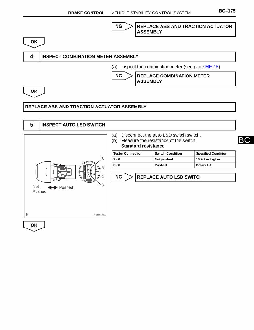
BRAKE CONTROL – VEHICLE STABILITY CONTROL SYSTEM BC–175
BC
NG
OK
(a) Inspect the combination meter (see page ME-15).
NG
OK
(a) Disconnect the auto LSD switch switch.(b) Measure the resistance of the switch.
Standard resistance
NG
OK
REPLACE ABS AND TRACTION ACTUATOR ASSEMBLY
4 INSPECT COMBINATION METER ASSEMBLY
REPLACE COMBINATION METER ASSEMBLY
REPLACE ABS AND TRACTION ACTUATOR ASSEMBLY
5 INSPECT AUTO LSD SWITCH
Not Pushed
Pushed
6
5
4
3
C128532E02
Tester Connection Switch Condition Specified Condition
3 - 6 Not pushed 10 kΩ or higher
3 - 6 Pushed Below 1Ω
REPLACE AUTO LSD SWITCH
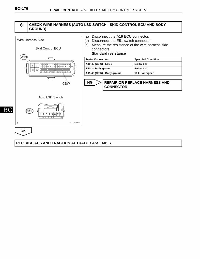
BC–176 BRAKE CONTROL – VEHICLE STABILITY CONTROL SYSTEM
BC
(a) Disconnect the A19 ECU connector.(b) Disconnect the E51 switch connector.(c) Measure the resistance of the wire harness side
connectors.Standard resistance
NG
OK
6 CHECK WIRE HARNESS (AUTO LSD SWITCH - SKID CONTROL ECU AND BODY GROUND)
1 3 4 5 6 7 8 9 10 11 12 13 14 15 1617 18 19 20 21 22 23 24 25 26 27 28 29 30
33 34 35 36 37 38 39 40 41 42 43 44 45 46
2
31 32
1 2 3 4 5 6 7 8
Wire Harness Side
Skid Control ECU
A19
E51
Auto LSD Switch
CSW
C131915E02
Tester Connection Specified Condition
A19-43 (CSW) - E51-6 Below 1 Ω
E51-3 - Body ground Below 1 Ω
A19-43 (CSW) - Body ground 10 kΩ or higher
REPAIR OR REPLACE HARNESS AND CONNECTOR
REPLACE ABS AND TRACTION ACTUATOR ASSEMBLY
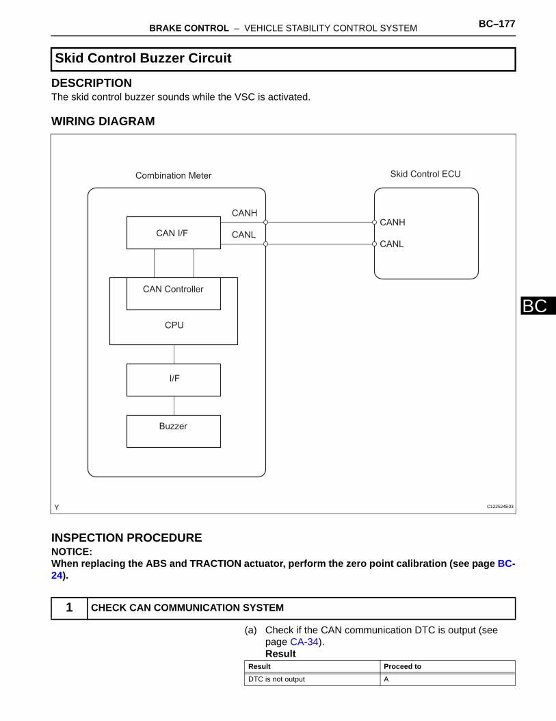
BRAKE CONTROL – VEHICLE STABILITY CONTROL SYSTEM BC–177
BC
DESCRIPTIONThe skid control buzzer sounds while the VSC is activated.
WIRING DIAGRAM
INSPECTION PROCEDURENOTICE:When replacing the ABS and TRACTION actuator, perform the zero point calibration (see page BC-24).
(a) Check if the CAN communication DTC is output (see page CA-34).Result
Skid Control Buzzer Circuit
1 CHECK CAN COMMUNICATION SYSTEM
Combination Meter
CAN I/F
CAN Controller
CPU
I/F
Buzzer
Skid Control ECU
CANH
CANL
CANH
CANL
C122524E03
Result Proceed to
DTC is not output A
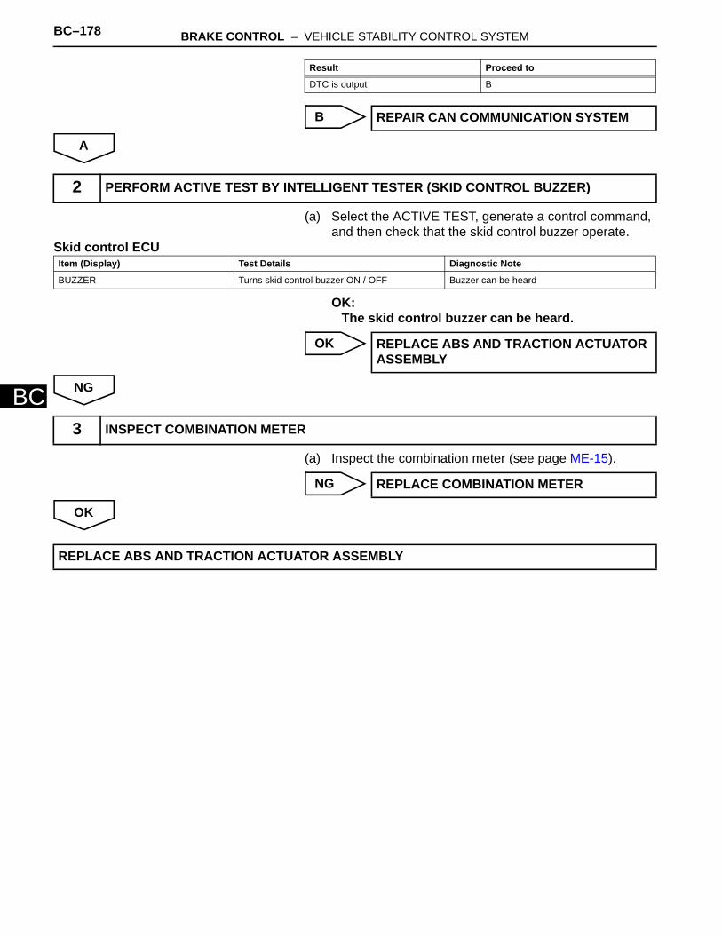
BC–178 BRAKE CONTROL – VEHICLE STABILITY CONTROL SYSTEM
BC
B
A
(a) Select the ACTIVE TEST, generate a control command, and then check that the skid control buzzer operate.
Skid control ECU
OK:The skid control buzzer can be heard.
OK
NG
(a) Inspect the combination meter (see page ME-15).
NG
OK
DTC is output B
REPAIR CAN COMMUNICATION SYSTEM
Result Proceed to
2 PERFORM ACTIVE TEST BY INTELLIGENT TESTER (SKID CONTROL BUZZER)
Item (Display) Test Details Diagnostic Note
BUZZER Turns skid control buzzer ON / OFF Buzzer can be heard
REPLACE ABS AND TRACTION ACTUATOR ASSEMBLY
3 INSPECT COMBINATION METER
REPLACE COMBINATION METER
REPLACE ABS AND TRACTION ACTUATOR ASSEMBLY
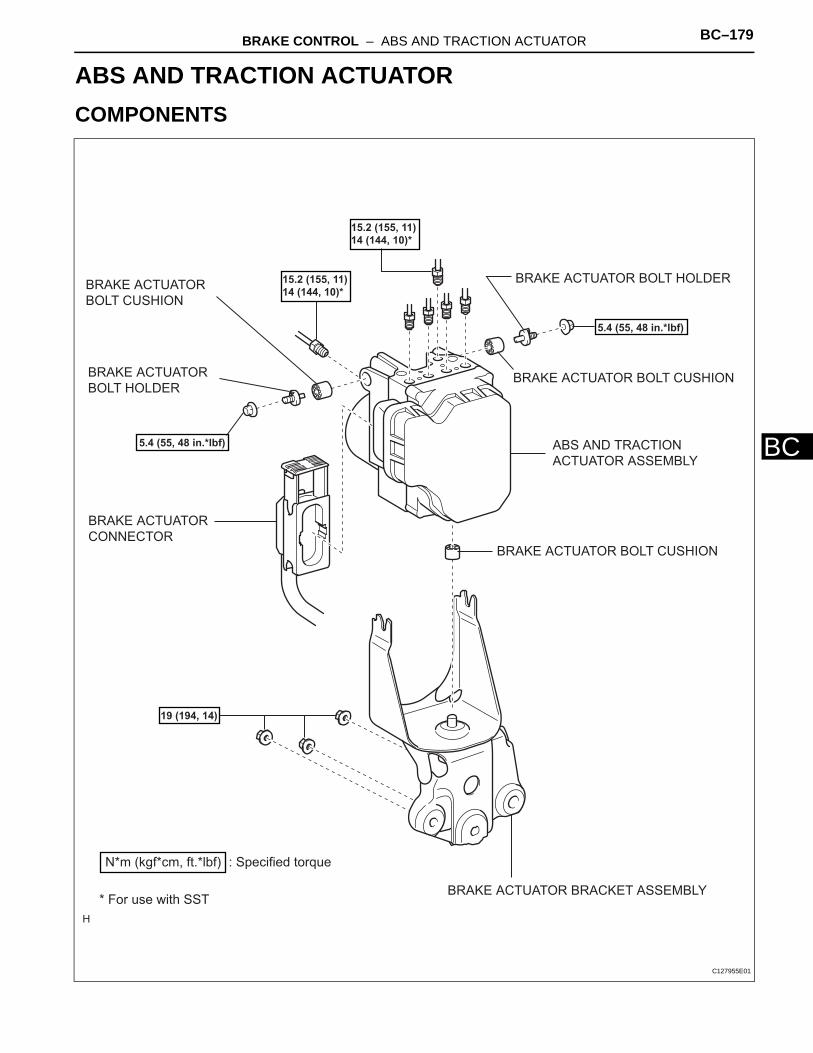
BRAKE CONTROL – ABS AND TRACTION ACTUATOR BC–179
BC
BRAKEBRAKE CONTROLABS AND TRACTION ACTUATORCOMPONENTS
ABS AND TRACTION
ACTUATOR ASSEMBLY
BRAKE ACTUATOR BOLT CUSHION
BRAKE ACTUATOR BOLT HOLDER
BRAKE ACTUATOR BOLT CUSHION
BRAKE ACTUATOR BRACKET ASSEMBLY
BRAKE ACTUATOR
CONNECTOR
BRAKE ACTUATOR
BOLT HOLDER
BRAKE ACTUATOR
BOLT CUSHION
: Specified torqueN*m (kgf*cm, ft.*lbf)
19 (194, 14)
5.4 (55, 48 in.*lbf)
5.4 (55, 48 in.*lbf)
* For use with SST
15.2 (155, 11)
14 (144, 10)*
15.2 (155, 11)
14 (144, 10)*
C127955E01

BC–180 BRAKE CONTROL – ABS AND TRACTION ACTUATOR
BC
ON-VEHICLE INSPECTION1. CONNECT INTELLIGENT TESTER
(a) Connect the intelligent tester to the DLC3.(b) Start the engine and idle it.(c) Select the Active Test mode on the intelligent tester.
HINT:Please refer to the intelligent tester operator's manual for further details.
2. CHECK ACTUATOR MOTOR OPERATIONNOTICE:Do not keep a motor relay ON for more than 5 seconds. When operating it consecutively, wait 20 seconds between each operation.(a) Turn the motor relay ON and check the actuator
motor operation noise.(b) Turn the motor relay OFF.(c) Fully depress the brake pedal and hold it for
approximately 15 seconds. Check that the pedal's initial depth is maintained for the entire 15 seconds.
(d) Turn the motor relay ON and check that the pedal does not pulsate.
(e) Turn the motor relay OFF and release the pedal.
3. CHECK BRAKE ACTUATOR SOLENOID (for Front Right Wheel)NOTICE:• Be sure to follow the procedures below when
turning ON a solenoid.• Do not keep a solenoid ON for more than 10
seconds. When operating it consecutively, wait 20 seconds between each operation.
• Do not keep a motor relay ON for more than 5 seconds. When operating it consecutively, wait 20 seconds between each operation.
(a) With the pedal depressed as much as possible, perform the following operations.(1) Turn the SFRH and SFRR solenoids ON
simultaneously, and check that the pedal cannot be depressed further.
(2) Turn the SFRH and SFRR solenoids OFF simultaneously, and check that the pedal can be depressed further.
(3) Turn the motor relay ON. Check that the pedal returns to the "depressed as much as possible" position.
(b) Turn the motor relay OFF and release the pedal.
4. CHECK BRAKE ACTUATOR SOLENOID (for Front Left Wheel)(a) Use the same procedures described for the front
right wheel to check the solenoids of the front left wheel.HINT:Front left wheel: SFLH, SFLR
Intelligent Tester
CAN VIM
DLC3
B127989E01
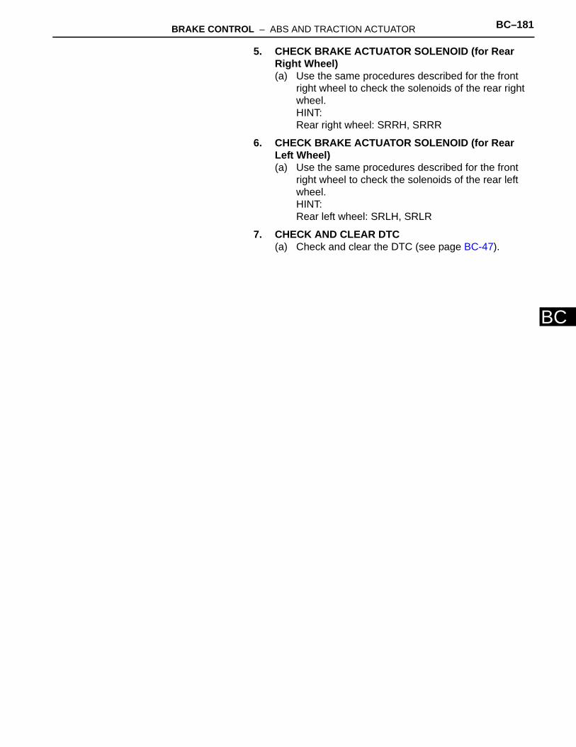
BRAKE CONTROL – ABS AND TRACTION ACTUATOR BC–181
BC
5. CHECK BRAKE ACTUATOR SOLENOID (for Rear Right Wheel)(a) Use the same procedures described for the front
right wheel to check the solenoids of the rear right wheel.HINT:Rear right wheel: SRRH, SRRR
6. CHECK BRAKE ACTUATOR SOLENOID (for Rear Left Wheel)(a) Use the same procedures described for the front
right wheel to check the solenoids of the rear left wheel.HINT:Rear left wheel: SRLH, SRLR
7. CHECK AND CLEAR DTC(a) Check and clear the DTC (see page BC-47).
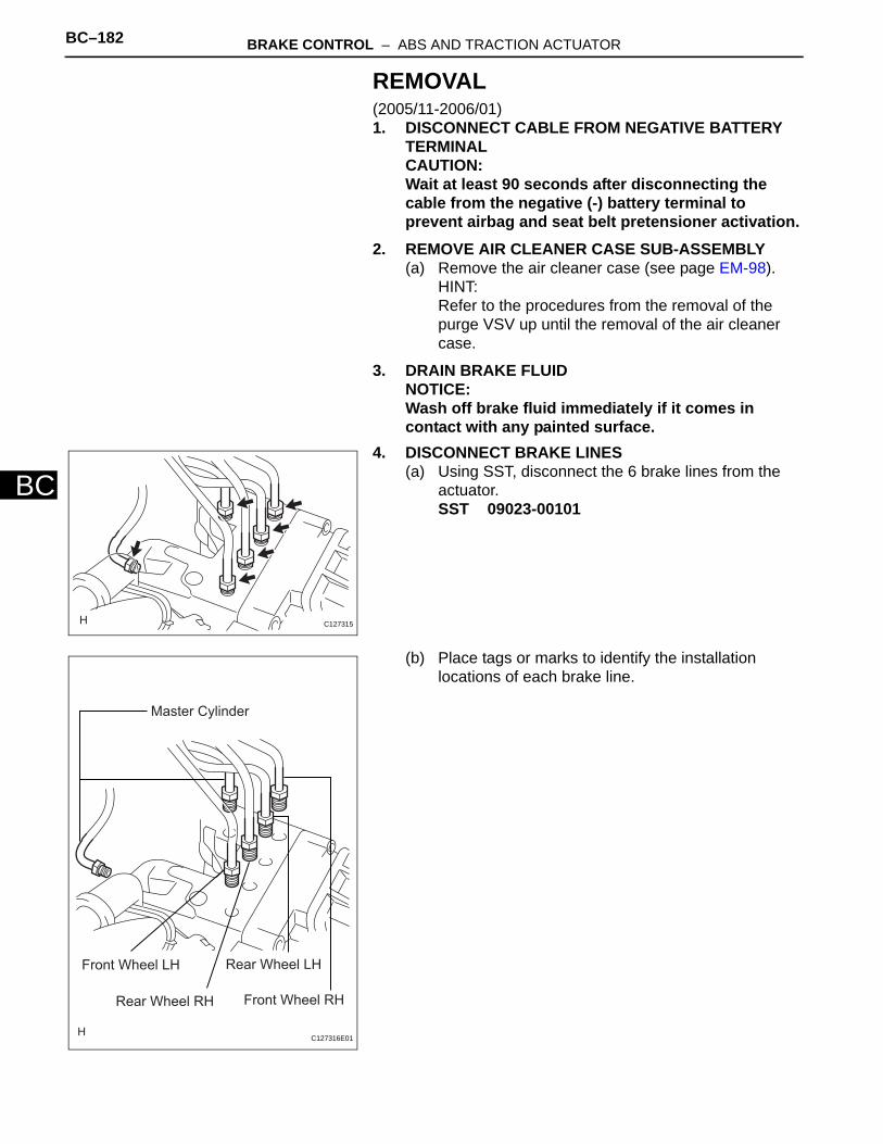
BC–182 BRAKE CONTROL – ABS AND TRACTION ACTUATOR
BC
REMOVAL(2005/11-2006/01)1. DISCONNECT CABLE FROM NEGATIVE BATTERY
TERMINALCAUTION:Wait at least 90 seconds after disconnecting the cable from the negative (-) battery terminal to prevent airbag and seat belt pretensioner activation.
2. REMOVE AIR CLEANER CASE SUB-ASSEMBLY(a) Remove the air cleaner case (see page EM-98).
HINT:Refer to the procedures from the removal of the purge VSV up until the removal of the air cleaner case.
3. DRAIN BRAKE FLUIDNOTICE:Wash off brake fluid immediately if it comes in contact with any painted surface.
4. DISCONNECT BRAKE LINES(a) Using SST, disconnect the 6 brake lines from the
actuator.SST 09023-00101
(b) Place tags or marks to identify the installation locations of each brake line.
C127315
Front Wheel LH
Front Wheel RH
Rear Wheel LH
Rear Wheel RH
Master Cylinder
C127316E01
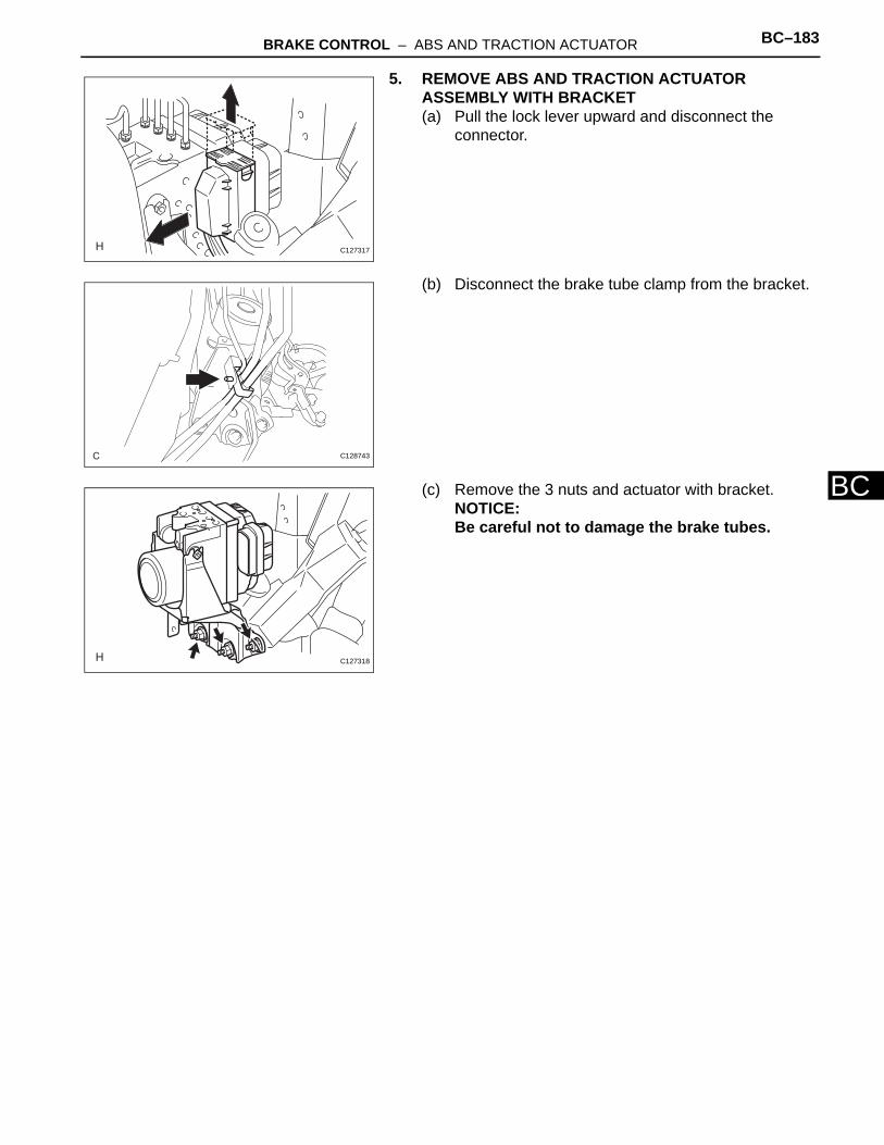
BRAKE CONTROL – ABS AND TRACTION ACTUATOR BC–183
BC
5. REMOVE ABS AND TRACTION ACTUATOR ASSEMBLY WITH BRACKET(a) Pull the lock lever upward and disconnect the
connector.
(b) Disconnect the brake tube clamp from the bracket.
(c) Remove the 3 nuts and actuator with bracket.NOTICE:Be careful not to damage the brake tubes.
C127317
C128743
C127318
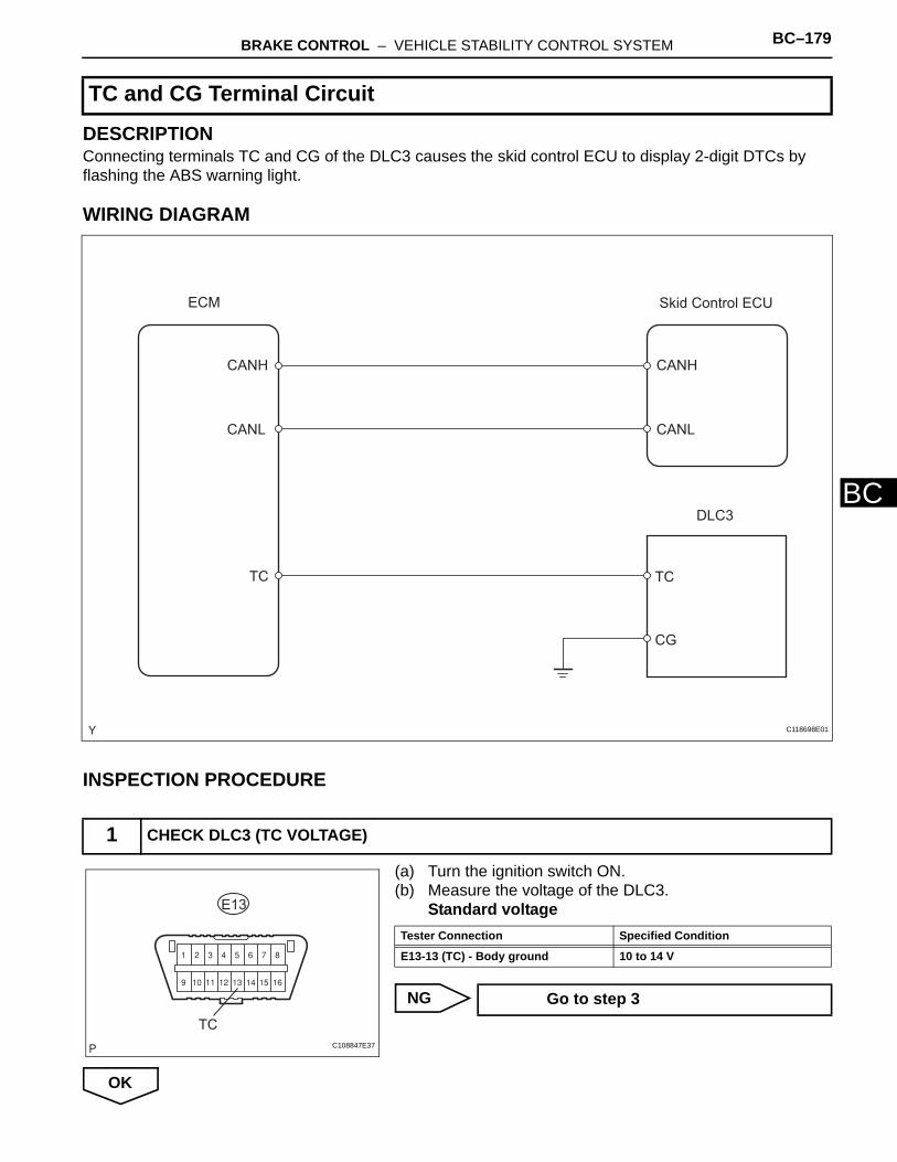
BRAKE CONTROL – VEHICLE STABILITY CONTROL SYSTEM BC–179
BC
DESCRIPTIONConnecting terminals TC and CG of the DLC3 causes the skid control ECU to display 2-digit DTCs by flashing the ABS warning light.
WIRING DIAGRAM
INSPECTION PROCEDURE
(a) Turn the ignition switch ON.(b) Measure the voltage of the DLC3.
Standard voltage
NG
OK
TC and CG Terminal Circuit
1 CHECK DLC3 (TC VOLTAGE)
Skid Control ECU
CANH
CANL
CANH
CANL
ECM
CG
TCTC
DLC3
C118698E01
TC
E13
C108847E37
Tester Connection Specified Condition
E13-13 (TC) - Body ground 10 to 14 V
Go to step 3
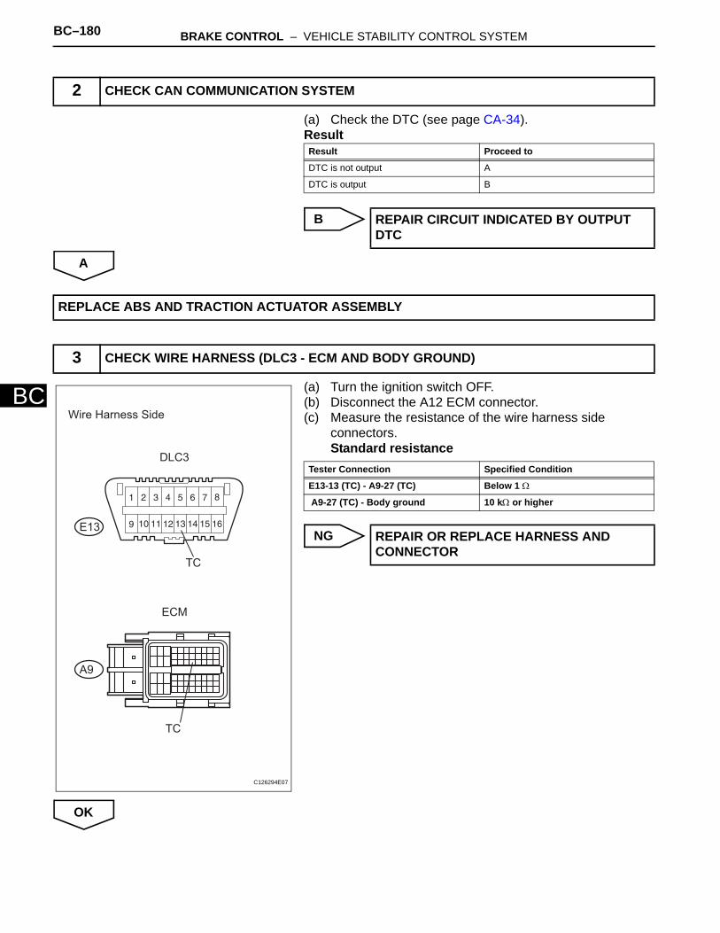
BC–180 BRAKE CONTROL – VEHICLE STABILITY CONTROL SYSTEM
BC
(a) Check the DTC (see page CA-34).Result
B
A
(a) Turn the ignition switch OFF.(b) Disconnect the A12 ECM connector. (c) Measure the resistance of the wire harness side
connectors.Standard resistance
NG
OK
2 CHECK CAN COMMUNICATION SYSTEM
Result Proceed to
DTC is not output A
DTC is output B
REPAIR CIRCUIT INDICATED BY OUTPUT DTC
REPLACE ABS AND TRACTION ACTUATOR ASSEMBLY
3 CHECK WIRE HARNESS (DLC3 - ECM AND BODY GROUND)
Wire Harness Side
DLC3
ECM
E13
A9
TC
TC
C126294E07
Tester Connection Specified Condition
E13-13 (TC) - A9-27 (TC) Below 1 Ω
A9-27 (TC) - Body ground 10 kΩ or higher
REPAIR OR REPLACE HARNESS AND CONNECTOR
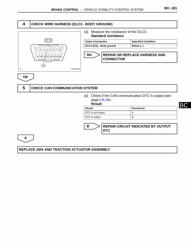
BRAKE CONTROL – VEHICLE STABILITY CONTROL SYSTEM BC–181
BC
(a) Measure the resistance of the DLC3.Standard resistance
NG
OK
(a) Check if the CAN communication DTC is output (see page CA-34).Result
B
A
4 CHECK WIRE HARNESS (DLC3 - BODY GROUND)
E13
CGH100769E63
Tester Connection Specified Condition
E13-4 (CG) - Body ground Below 1 Ω
REPAIR OR REPLACE HARNESS AND CONNECTOR
5 CHECK CAN COMMUNICATION SYSTEM
Result Proceed to
DTC is not output A
DTC is output B
REPAIR CIRCUIT INDICATED BY OUTPUT DTC
REPLACE ABS AND TRACTION ACTUATOR ASSEMBLY
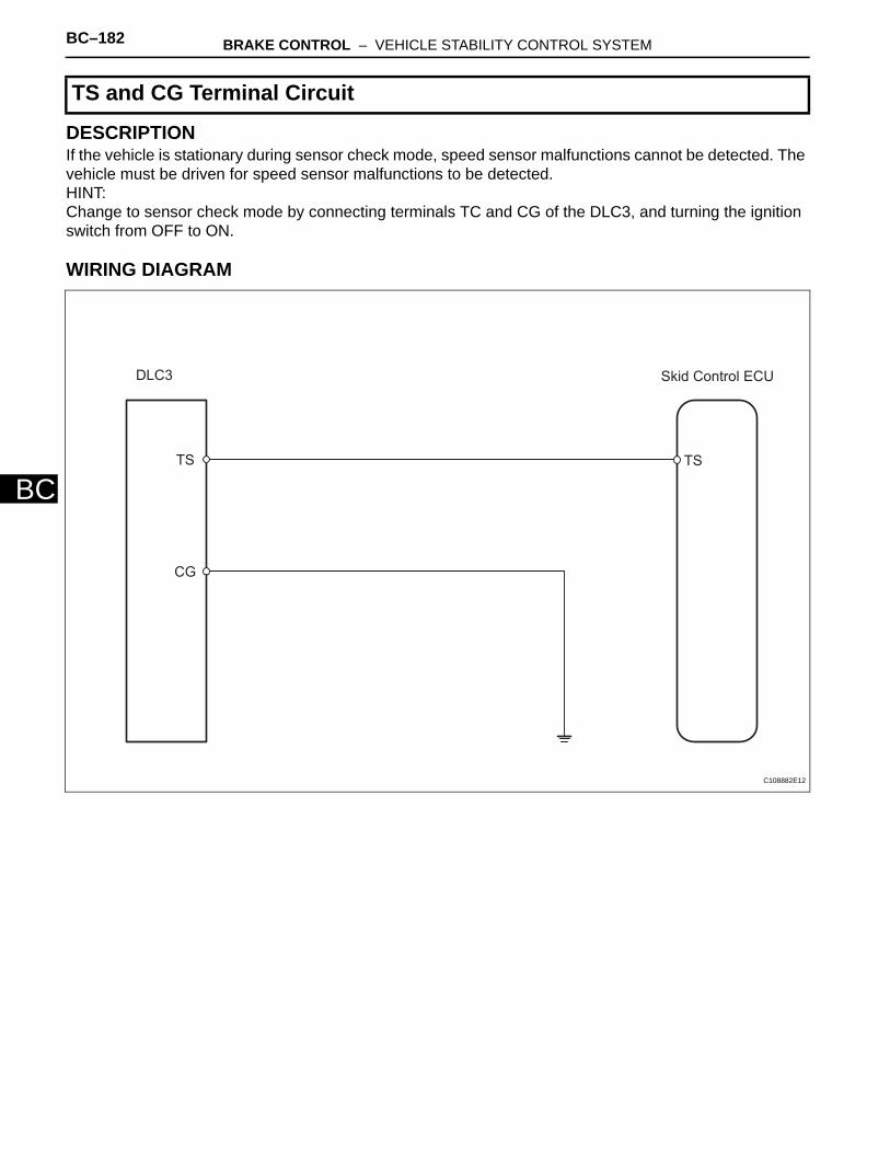
BC–182 BRAKE CONTROL – VEHICLE STABILITY CONTROL SYSTEM
BC
DESCRIPTIONIf the vehicle is stationary during sensor check mode, speed sensor malfunctions cannot be detected. The vehicle must be driven for speed sensor malfunctions to be detected.HINT:Change to sensor check mode by connecting terminals TC and CG of the DLC3, and turning the ignition switch from OFF to ON.
WIRING DIAGRAM
TS and CG Terminal Circuit
Skid Control ECU
TSTS
CG
DLC3
C108882E12
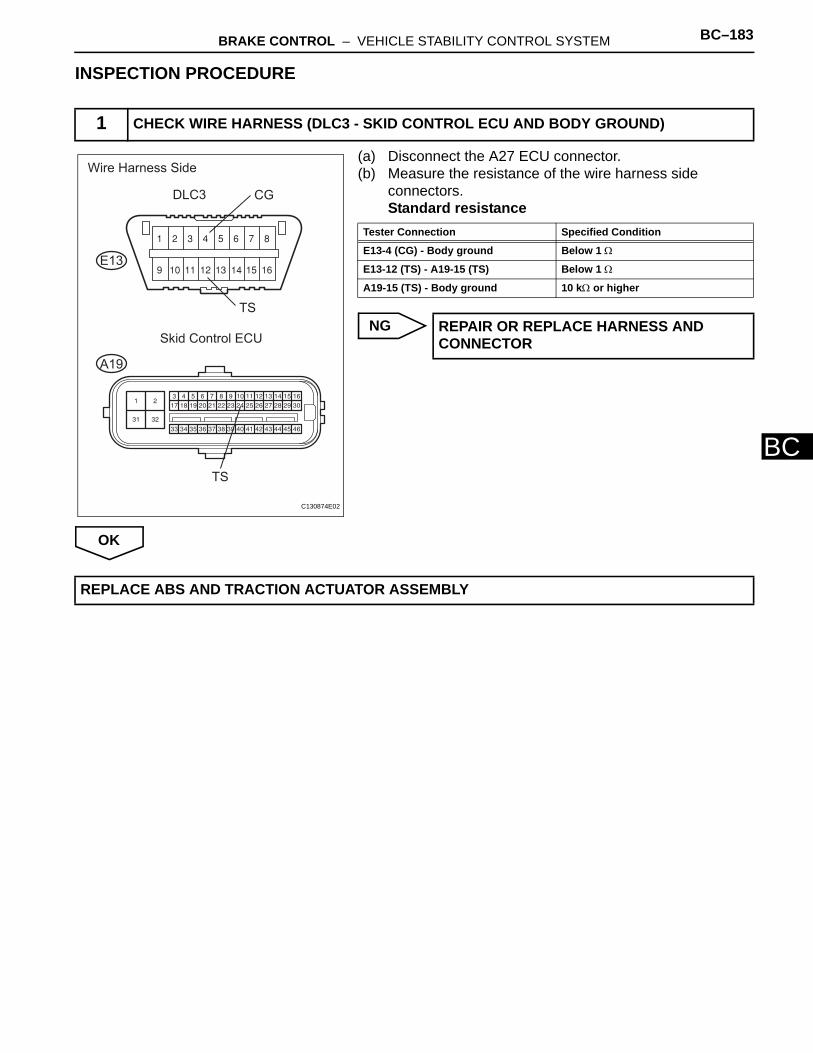
BRAKE CONTROL – VEHICLE STABILITY CONTROL SYSTEM BC–183
BC
INSPECTION PROCEDURE
(a) Disconnect the A27 ECU connector.(b) Measure the resistance of the wire harness side
connectors.Standard resistance
NG
OK
1 CHECK WIRE HARNESS (DLC3 - SKID CONTROL ECU AND BODY GROUND)
Wire Harness Side
DLC3
E13
A19
Skid Control ECU
CG
TS
TS
C130874E02
Tester Connection Specified Condition
E13-4 (CG) - Body ground Below 1 Ω
E13-12 (TS) - A19-15 (TS) Below 1 Ω
A19-15 (TS) - Body ground 10 kΩ or higher
REPAIR OR REPLACE HARNESS AND CONNECTOR
REPLACE ABS AND TRACTION ACTUATOR ASSEMBLY

BC–184 BRAKE CONTROL – ABS AND TRACTION ACTUATOR
BC
REMOVAL(2006/01- )1. DISCONNECT CABLE FROM NEGATIVE BATTERY
TERMINALCAUTION:Wait at least 90 seconds after disconnecting the cable from the negative (-) battery terminal to prevent airbag and seat belt pretensioner activation.
2. REMOVE AIR CLEANER CASE SUB-ASSEMBLY (for 2AZ-FE)(a) Remove the air cleaner case (see page EM-98).
HINT:Refer to the procedures from the removal of the purge VSV up until the removal of the air cleaner case.
3. REMOVE AIR CLEANER CASE (for 2GR-FE)(a) Remove the air cleaner case (see page EM-21).
HINT:Refer to the procedures from the removal of the air cleaner cap sub-assembly up until the removal of the air cleaner case.
4. DRAIN BRAKE FLUIDNOTICE:Wash off brake fluid immediately if it comes in contact with any painted surface.
5. DISCONNECT BRAKE LINES(a) Using SST, disconnect the 6 brake lines from the
actuator.SST 09023-00101
C127315
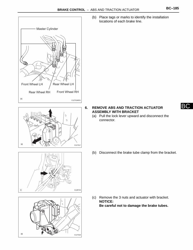
BRAKE CONTROL – ABS AND TRACTION ACTUATOR BC–185
BC
(b) Place tags or marks to identify the installation locations of each brake line.
6. REMOVE ABS AND TRACTION ACTUATOR ASSEMBLY WITH BRACKET(a) Pull the lock lever upward and disconnect the
connector.
(b) Disconnect the brake tube clamp from the bracket.
(c) Remove the 3 nuts and actuator with bracket.NOTICE:Be careful not to damage the brake tubes.
Front Wheel LH
Front Wheel RH
Rear Wheel LH
Rear Wheel RH
Master Cylinder
C127316E01
C127317
C128743
C127318
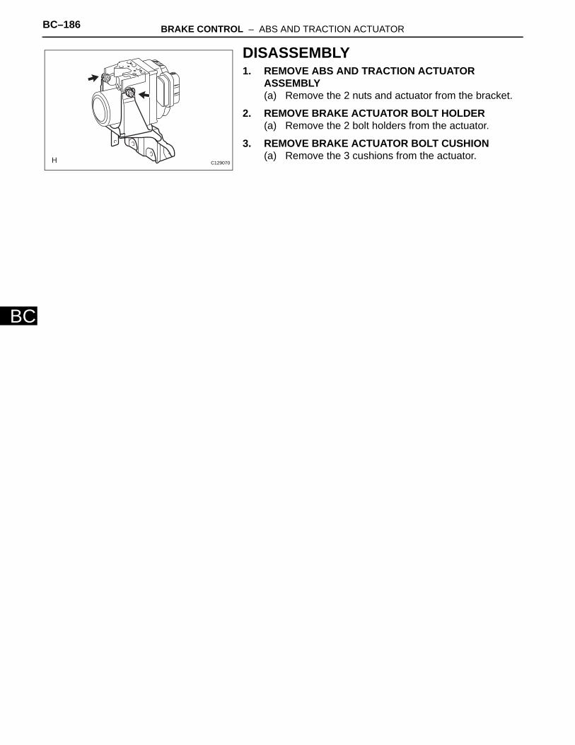
BC–186 BRAKE CONTROL – ABS AND TRACTION ACTUATOR
BC
DISASSEMBLY1. REMOVE ABS AND TRACTION ACTUATOR
ASSEMBLY(a) Remove the 2 nuts and actuator from the bracket.
2. REMOVE BRAKE ACTUATOR BOLT HOLDER(a) Remove the 2 bolt holders from the actuator.
3. REMOVE BRAKE ACTUATOR BOLT CUSHION(a) Remove the 3 cushions from the actuator.
C129070

BRAKE CONTROL – ABS AND TRACTION ACTUATOR BC–187
BC
REASSEMBLY1. INSTALL BRAKE ACTUATOR BOLT CUSHION
(a) Install the 3 cushions to the actuator.
2. INSTALL BRAKE ACTUATOR BOLT HOLDER(a) Install the 2 bolt holders to the actuator.
3. INSTALL ABS AND TRACTION ACTUATOR ASSEMBLYNOTICE:Do not remove the hole plug before connecting the brake tube. New actuators are filled with brake fluid.(a) Set the actuator on the bracket.
NOTICE:• Insert the cushion to the pin of the bracket
securely.
• The clearance between the bolt holder and bracket is less than 1.0 mm (0.039 in.).
• The projection should be set as shown in the illustration.
Cushion
Pin Bracket
C127958E01
Bolt HolderProjection
Bracket
1.0 mm or less
C127959E01
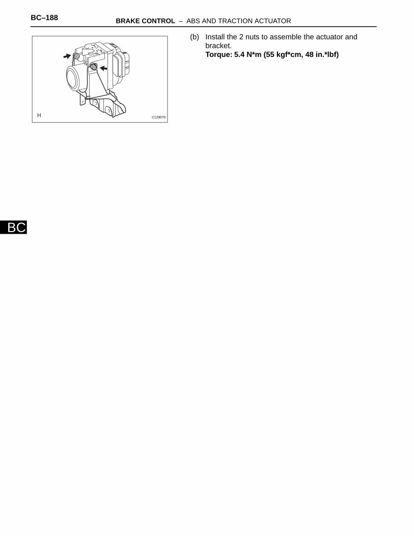
BC–188 BRAKE CONTROL – ABS AND TRACTION ACTUATOR
BC
(b) Install the 2 nuts to assemble the actuator and bracket.Torque: 5.4 N*m (55 kgf*cm, 48 in.*lbf)
C129070

BRAKE CONTROL – ABS AND TRACTION ACTUATOR BC–189
BC
INSTALLATION(2005/11-2006/01)1. INSTALL ABS AND TRACTION ACTUATOR
ASSEMBLY WITH BRACKETNOTICE:Do not remove the hole plug before connecting the brake tube. New actuators are filled with brake fluid.(a) Install the actuator with bracket with the 3 nuts.
Torque: 19 N*m (194 kgf*cm, 14 ft.*lbf)HINT:The nuts should be tightened in order from 1 to 3 as shown in the illustration.NOTICE:Be careful not to damage the brake tubes.
(b) Connect the brake tube clamp to the bracket.
(c) Connect the connector and push the lock lever downward.
3
12
C127318E01
C128743
C128530

BC–190 BRAKE CONTROL – ABS AND TRACTION ACTUATOR
BC
2. CONNECT BRAKE LINES(a) Using SST, connect the 6 brake lines to the correct
locations on the actuator, as shown in the illustration.SST 09023-00101Torque: 15.2 N*m (155 kgf*cm, 11 ft.*lbf) without
SST14 N*m (144 kgf*cm, 10 ft.*lbf) with SST
HINT:Use a torque wrench with a fulcrum length of 30 cm (11.81 in.).
3. FILL RESERVOIR WITH BRAKE FLUID (See page BR-6)
4. BLEED AIR FROM BRAKE MASTER CYLINDER (See page BR-7)
5. BLEED AIR FROM BRAKE LINE (See page BR-7)6. BLEED AIR FROM ABS AND TRACTION ACTUATOR
ASSEMBLY (See page BR-8)7. CHECK BRAKE FLUID LEVEL IN RESERVOIR (See
page BR-6)8. CHECK FOR BRAKE FLUID LEAKAGE9. INSTALL AIR CLEANER CASE SUB-ASSEMBLY
(a) Install the air cleaner case (see page EM-105).HINT:Refer to the procedures from the installation of the air cleaner case up until the installation of the purge VSV.
10. CONNECT CABLE TO NEGATIVE BATTERY TERMINAL
11. CHECK ABS AND TRACTION ACTUATOR ASSEMBLY WITH INTELLIGENT TESTER(a) Check the ABS and traction actuator with the
intelligent tester (see page BC-180).
Front Wheel LH
Front Wheel RH
Rear Wheel LH
Rear Wheel RH
Master Cylinder
C127316E01
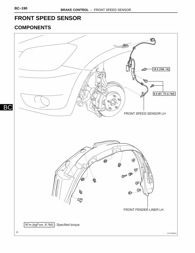
BC–190 BRAKE CONTROL – FRONT SPEED SENSOR
BC
BRAKEBRAKE CONTROLFRONT SPEED SENSORCOMPONENTS
FRONT FENDER LINER LH
: Specified torqueN*m (kgf*cm, ft.*lbf)
8.5 (87, 75 in.*lbf)
18.5 (189, 14)
FRONT SPEED SENSOR LH
C127325E01

BRAKE CONTROL – FRONT SPEED SENSOR BC–191
BC
REMOVALHINT:• Use the same procedures for the LH side and RH side.• The procedures listed below are for the LH side.
1. DISCONNECT CABLE FROM NEGATIVE BATTERY TERMINALCAUTION:Wait at least 90 seconds after disconnecting the cable from the negative (-) battery terminal to prevent airbag and seat belt pretensioner activation.
2. REMOVE FRONT WHEEL3. REMOVE FRONT FENDER LINER LH4. REMOVE FRONT SPEED SENSOR LH
(a) Disconnect the sensor connector.
C127964E01
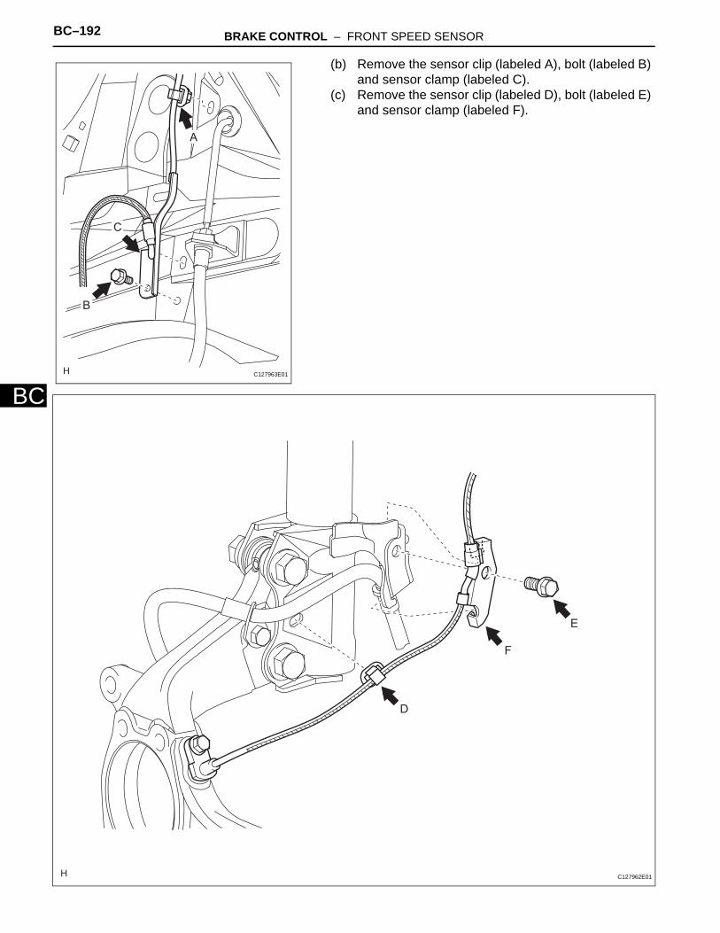
BC–192 BRAKE CONTROL – FRONT SPEED SENSOR
BC
(b) Remove the sensor clip (labeled A), bolt (labeled B) and sensor clamp (labeled C).
(c) Remove the sensor clip (labeled D), bolt (labeled E) and sensor clamp (labeled F).
A
B
C
C127963E01
D
E
F
C127962E01

BRAKE CONTROL – FRONT SPEED SENSOR BC–193
BC
(d) Remove the bolt and sensor body from the knuckle.NOTICE:Keep the sensor tip and sensor installation hole free from foreign matter.
C127961E01
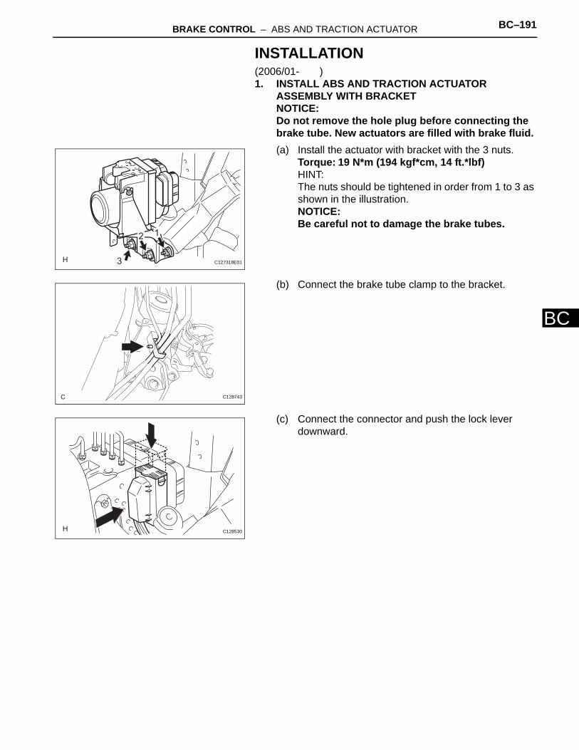
BRAKE CONTROL – ABS AND TRACTION ACTUATOR BC–191
BC
INSTALLATION(2006/01- )1. INSTALL ABS AND TRACTION ACTUATOR
ASSEMBLY WITH BRACKETNOTICE:Do not remove the hole plug before connecting the brake tube. New actuators are filled with brake fluid.(a) Install the actuator with bracket with the 3 nuts.
Torque: 19 N*m (194 kgf*cm, 14 ft.*lbf)HINT:The nuts should be tightened in order from 1 to 3 as shown in the illustration.NOTICE:Be careful not to damage the brake tubes.
(b) Connect the brake tube clamp to the bracket.
(c) Connect the connector and push the lock lever downward.
3
12
C127318E01
C128743
C128530

BC–192 BRAKE CONTROL – ABS AND TRACTION ACTUATOR
BC
2. CONNECT BRAKE LINES(a) Using SST, connect the 6 brake lines to the correct
locations on the actuator, as shown in the illustration.SST 09023-00101Torque: 15.2 N*m (155 kgf*cm, 11 ft.*lbf) without
SST14 N*m (144 kgf*cm, 10 ft.*lbf) with SST
HINT:Use a torque wrench with a fulcrum length of 30 cm (11.81 in.).
3. FILL RESERVOIR WITH BRAKE FLUID (See page BR-6)
4. BLEED AIR FROM BRAKE MASTER CYLINDER (See page BR-7)
5. BLEED AIR FROM BRAKE LINE (See page BR-7)6. BLEED AIR FROM ABS AND TRACTION ACTUATOR
ASSEMBLY (See page BR-8)7. CHECK BRAKE FLUID LEVEL IN RESERVOIR (See
page BR-6)8. CHECK FOR BRAKE FLUID LEAKAGE9. INSTALL AIR CLEANER CASE SUB-ASSEMBLY (for
2AZ-FE)(a) Install the air cleaner case (see page EM-105).
HINT:Refer to the procedures from the installation of the air cleaner case up until the installation of the purge VSV.
10. INSTALL AIR CLEANER CASE (for 2GR-FE)(a) Install the air cleaner case (see page EM-31).
HINT:Refer to the procedures from the installation of the air cleaner case up until the installation of the air cleaner cap sub-assembly.
11. CONNECT CABLE TO NEGATIVE BATTERY TERMINAL
12. CHECK ABS AND TRACTION ACTUATOR ASSEMBLY WITH INTELLIGENT TESTER(a) Check the ABS and traction actuator with the
intelligent tester (see page BC-180).
Front Wheel LH
Front Wheel RH
Rear Wheel LH
Rear Wheel RH
Master Cylinder
C127316E01

BC–194 BRAKE CONTROL – FRONT SPEED SENSOR
BC
INSPECTION1. INSPECT FRONT SPEED SENSOR
(a) Check the speed sensor. If any of the following occurs, replace the speed sensor with a new one.• The surface of the speed sensor is cracked,
dented, or chipped.• The connector or wire harness is scratched,
cracked, or damaged.• The speed sensor has been dropped.
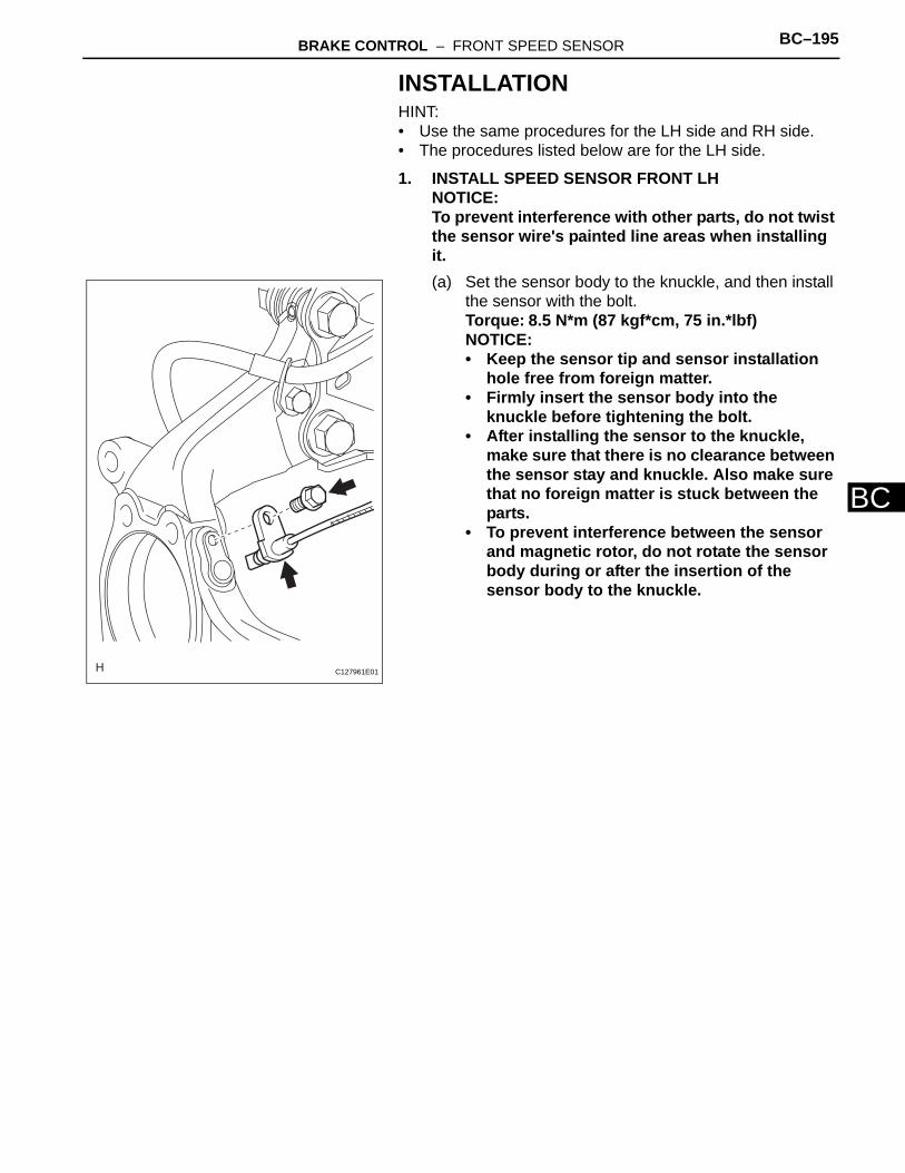
BRAKE CONTROL – FRONT SPEED SENSOR BC–195
BC
INSTALLATIONHINT:• Use the same procedures for the LH side and RH side.• The procedures listed below are for the LH side.
1. INSTALL SPEED SENSOR FRONT LHNOTICE:To prevent interference with other parts, do not twist the sensor wire's painted line areas when installing it.(a) Set the sensor body to the knuckle, and then install
the sensor with the bolt.Torque: 8.5 N*m (87 kgf*cm, 75 in.*lbf)NOTICE:• Keep the sensor tip and sensor installation
hole free from foreign matter.• Firmly insert the sensor body into the
knuckle before tightening the bolt.• After installing the sensor to the knuckle,
make sure that there is no clearance between the sensor stay and knuckle. Also make sure that no foreign matter is stuck between the parts.
• To prevent interference between the sensor and magnetic rotor, do not rotate the sensor body during or after the insertion of the sensor body to the knuckle.
C127961E01

BC–196 BRAKE CONTROL – FRONT SPEED SENSOR
BC
(b) Install the sensor clamp and sensor clip as follows.
(1) Set the flexible hose clamp on the flexible hose bracket.
(2) Simultaneously perform the following: 1) hang the hook part of the sensor clamp (labeled A) on the flexible hose bracket (labeled C); and 2) insert the hook part of the sensor clamp (labeled B) into the flexible hose bracket (labeled D).NOTICE:Do not twist the sensor wire when installing the clamp.
(3) Tighten together the sensor clamp, flexible hose clamp and flexible hose bracket with the bolt (labeled E).Torque: 18.5 N*m (189 kgf*cm, 14 ft.*lbf)
(4) Insert the sensor clip (labeled F) into the hole on the absorber lower bracket.
Painted Line
Flexible Hose Clamp
Flexible Hose Bracket
A
C
B
D
E
F
C127962E02
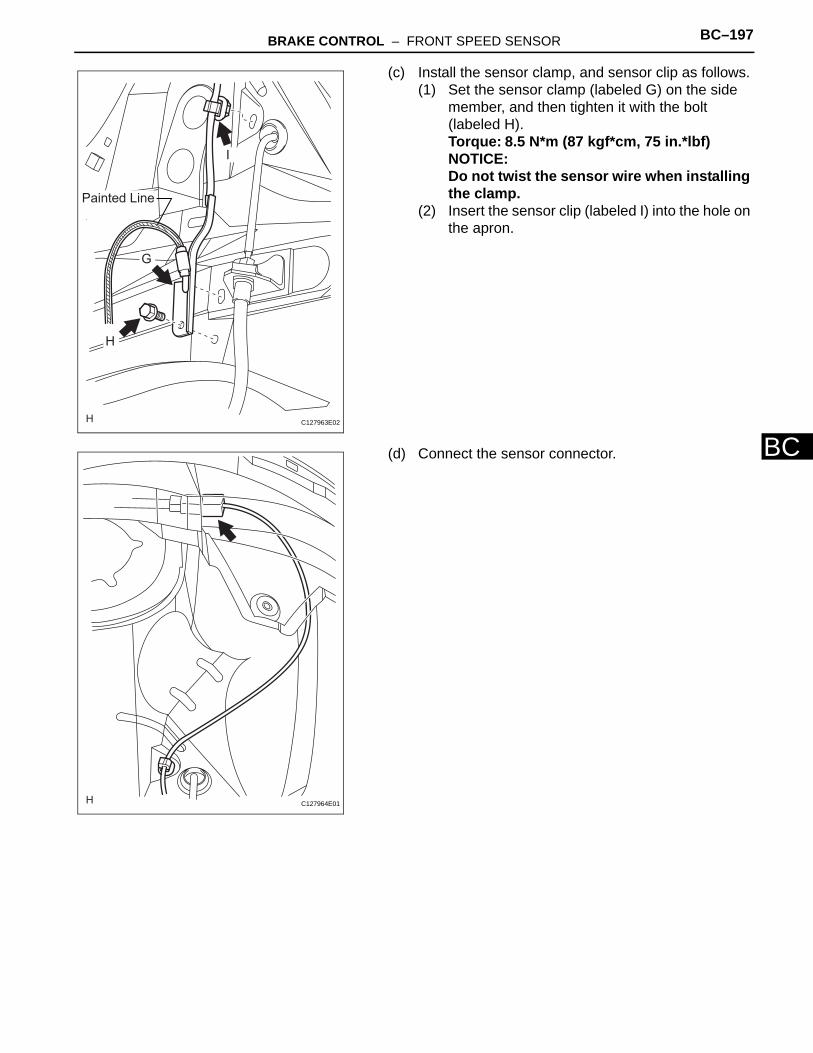
BRAKE CONTROL – FRONT SPEED SENSOR BC–197
BC
(c) Install the sensor clamp, and sensor clip as follows.(1) Set the sensor clamp (labeled G) on the side
member, and then tighten it with the bolt (labeled H).Torque: 8.5 N*m (87 kgf*cm, 75 in.*lbf)NOTICE:Do not twist the sensor wire when installing the clamp.
(2) Insert the sensor clip (labeled I) into the hole on the apron.
(d) Connect the sensor connector.
Painted Line
G
H
I
C127963E02
C127964E01

BC–198 BRAKE CONTROL – FRONT SPEED SENSOR
BC
2. INSTALL FRONT FENDER LINER LHHINT:Install the fender liner so that the sensor wire harness passes beyond the fender liner installation clip towards the rear side of the vehicle.
3. INSTALL FRONT WHEELTorque: 103 N*m (1,050 kgf*cm, 76 ft.*lbf)
4. CONNECT CABLE TO NEGATIVE BATTERY TERMINAL
5. CHECK ABS SPEED SENSOR SIGNAL(a) Check the speed sensor signal (see page BC-28).Clip
Rear
C127964E02

BRAKE CONTROL – SKID CONTROL SENSOR (for 2WD) BC–197
BC
BRAKEBRAKE CONTROLSKID CONTROL SENSOR (for 2WD)COMPONENTS
REAR AXLE HUB AND
BEARING ASSEMBLY LH
SKID CONTROL SENSOR WIRE
REAR DISC
REAR DISC BRAKE CYLINDER
MOUNTING LH
: Specified torqueN*m (kgf*cm, ft.*lbf)
88 (897, 65)
5.0 (51, 44 in.*lbf)
8.5 (87, 75 in.*lbf)
90 (918, 66)
SKID CONTROL SENSOR LH
x 4
C128535E01

BC–198 BRAKE CONTROL – SKID CONTROL SENSOR (for 2WD)
BC
REMOVALHINT:• Use the same procedures for the LH side and RH side.• The procedures listed below are for the LH side.
1. DISCONNECT CABLE FROM NEGATIVE BATTERY TERMINALCAUTION:Wait at least 90 seconds after disconnecting the cable from the negative (-) battery terminal to prevent airbag and seat belt pretensioner activation.
2. REMOVE REAR WHEEL3. REMOVE DECK TRIM SIDE PANEL ASSEMBLY LH
(a) Remove the deck trim side panel LH (see page IR-26).HINT:Refer to the procedures from the removal of the rear door scuff plate LH up until the removal of the deck trim side panel LH.
4. REMOVE SKID CONTROL SENSOR WIRE(a) Disconnect the skid control sensor wire connector.
(b) Disconnect the grommet of the skid control sensor wire from the hole of the wheel house.
C127328
C127970E01
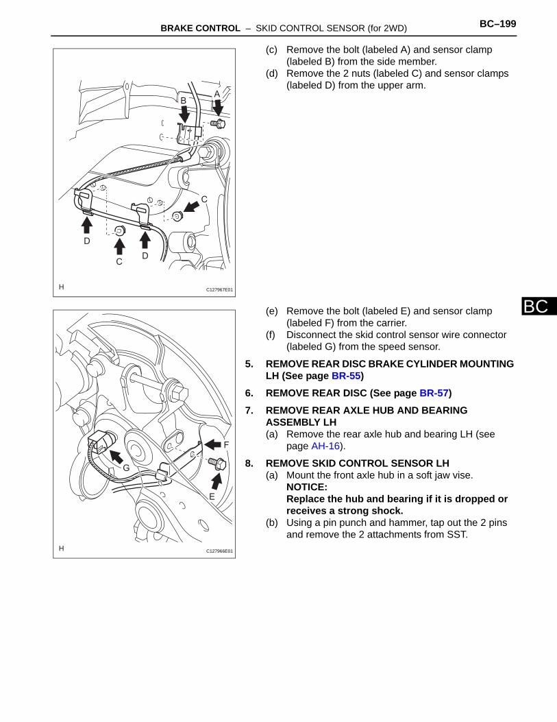
BRAKE CONTROL – SKID CONTROL SENSOR (for 2WD) BC–199
BC
(c) Remove the bolt (labeled A) and sensor clamp (labeled B) from the side member.
(d) Remove the 2 nuts (labeled C) and sensor clamps (labeled D) from the upper arm.
(e) Remove the bolt (labeled E) and sensor clamp (labeled F) from the carrier.
(f) Disconnect the skid control sensor wire connector (labeled G) from the speed sensor.
5. REMOVE REAR DISC BRAKE CYLINDER MOUNTING LH (See page BR-55)
6. REMOVE REAR DISC (See page BR-57)7. REMOVE REAR AXLE HUB AND BEARING
ASSEMBLY LH(a) Remove the rear axle hub and bearing LH (see
page AH-16).
8. REMOVE SKID CONTROL SENSOR LH(a) Mount the front axle hub in a soft jaw vise.
NOTICE:Replace the hub and bearing if it is dropped or receives a strong shock.
(b) Using a pin punch and hammer, tap out the 2 pins and remove the 2 attachments from SST.
C
A
C
B
D
D
C127967E01
E
F
G
C127966E01

BC–200 BRAKE CONTROL – SKID CONTROL SENSOR (for 2WD)
BC
(c) Using SST and the 2 bolts (diameter: 12 mm; pitch: 1.5 mm), remove the skid control sensor from the hub and bearing.SST 09520-00031 (09520-00040), 09521-00020,
09950-00020NOTICE:• If the sensor rotor is damaged, replace the
axle hub.• Do not scratch the contacting surface of the
hub and bearing and skid control sensor.
SST
SST
Bolt
C128748E01
BRAKE CONTROL – SKID CONTROL SENSOR (for 2WD) BC–201
BC
INSPECTION1. INSPECT SKID CONTROL SENSOR
(a) Check the speed sensor. If any of the following occurs, replace the speed sensor with a new one.• The surface of the speed sensor is cracked,
dented, or chipped.• The speed sensor has been dropped.
2. INSPECT SKID CONTROL SENSOR WIRE(a) Check the sensor wire. If any of the following
occurs, replace the sensor wire with a new one.The connector or wire harness is scratched, cracked, or damaged.

BC–202 BRAKE CONTROL – SKID CONTROL SENSOR (for 2WD)
BC
INSTALLATIONHINT:• Use the same procedures for the LH side and RH side.• The procedures listed below are for the LH side.
1. INSTALL SKID CONTROL SENSOR LH(a) Clean the contact surfaces of the axle hub and
speed sensor.NOTICE:Make sure the sensor rotor is clean.
(b) Place the speed sensor on the axle hub so that the connector position is as high as possible when the axle hub is installed to the vehicle.
(c) Using SST and a press, press the speed sensor into the hub and bearing.SST 09214-76011NOTICE:• Do not tap the speed sensor directly with a
hammer.• Check that the speed sensor detection part is
clean.• Press in the speed sensor straight and
slowly.2. INSTALL REAR AXLE HUB AND BEARING
ASSEMBLY LH(a) Install the rear axle hub and bearing LH (see page
AH-18).
3. INSTALL REAR DISC (See page BR-58)4. INSTALL REAR DISC BRAKE CYLINDER MOUNTING
LH (See page BR-60)5. INSTALL SKID CONTROL SENSOR WIRE
NOTICE:To prevent interference with other parts, do not twist the sensor wire's painted line areas when installing it.
Upward
C128749E01
SST
C128750E01
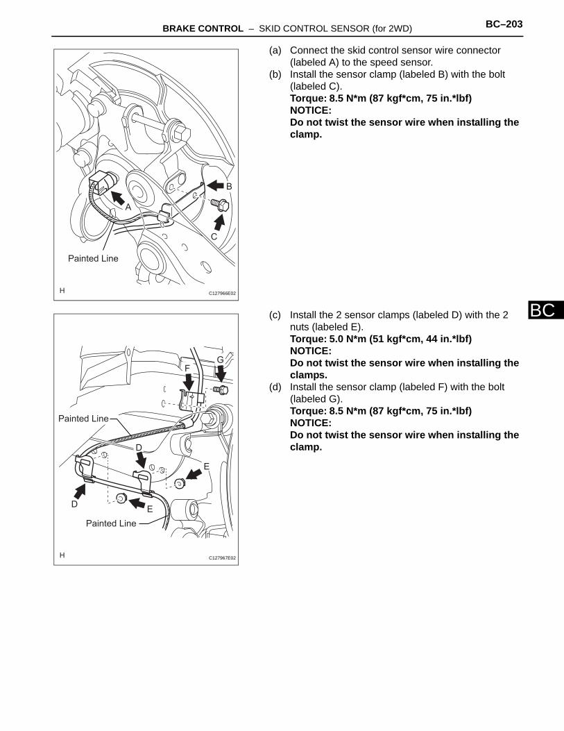
BRAKE CONTROL – SKID CONTROL SENSOR (for 2WD) BC–203
BC
(a) Connect the skid control sensor wire connector (labeled A) to the speed sensor.
(b) Install the sensor clamp (labeled B) with the bolt (labeled C).Torque: 8.5 N*m (87 kgf*cm, 75 in.*lbf)NOTICE:Do not twist the sensor wire when installing the clamp.
(c) Install the 2 sensor clamps (labeled D) with the 2 nuts (labeled E).Torque: 5.0 N*m (51 kgf*cm, 44 in.*lbf)NOTICE:Do not twist the sensor wire when installing the clamps.
(d) Install the sensor clamp (labeled F) with the bolt (labeled G).Torque: 8.5 N*m (87 kgf*cm, 75 in.*lbf)NOTICE:Do not twist the sensor wire when installing the clamp.
Painted Line
A
C
B
C127966E02
E
G
E
Painted Line
Painted Line
F
D
D
C127967E02
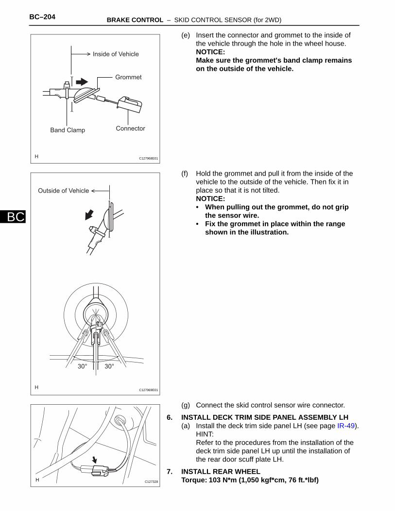
BC–204 BRAKE CONTROL – SKID CONTROL SENSOR (for 2WD)
BC
(e) Insert the connector and grommet to the inside of the vehicle through the hole in the wheel house.NOTICE:Make sure the grommet's band clamp remains on the outside of the vehicle.
(f) Hold the grommet and pull it from the inside of the vehicle to the outside of the vehicle. Then fix it in place so that it is not tilted.NOTICE:• When pulling out the grommet, do not grip
the sensor wire.• Fix the grommet in place within the range
shown in the illustration.
(g) Connect the skid control sensor wire connector.
6. INSTALL DECK TRIM SIDE PANEL ASSEMBLY LH(a) Install the deck trim side panel LH (see page IR-49).
HINT:Refer to the procedures from the installation of the deck trim side panel LH up until the installation of the rear door scuff plate LH.
7. INSTALL REAR WHEELTorque: 103 N*m (1,050 kgf*cm, 76 ft.*lbf)
Grommet
ConnectorBand Clamp
Inside of Vehicle
C127968E01
Outside of Vehicle
30°30°
C127969E01
C127328
BRAKE CONTROL – SKID CONTROL SENSOR (for 2WD) BC–205
BC
8. CONNECT CABLE TO NEGATIVE BATTERY TERMINAL
9. CHECK SPEED SENSOR SIGNAL(a) Check the speed sensor signal (see page BC-28).

BC–204 BRAKE CONTROL – REAR SPEED SENSOR (for 4WD)
BC
BRAKEBRAKE CONTROLREAR SPEED SENSOR (for 4WD)COMPONENTS
: Specified torqueN*m (kgf*cm, ft.*lbf)
5.0 (51, 44 in.*lbf)
5.0 (51, 44 in.*lbf)
8.5 (87, 75 in.*lbf)
8.5 (87, 75 in.*lbf)
REAR SPEED SENSOR LH
C128536E01

BRAKE CONTROL – REAR SPEED SENSOR (for 4WD) BC–205
BC
REMOVALHINT:• Use the same procedures for the LH side and RH side.• The procedures listed below are for the LH side.
1. DISCONNECT CABLE FROM NEGATIVE BATTERY TERMINALCAUTION:Wait at least 90 seconds after disconnecting the cable from the negative (-) battery terminal to prevent airbag and seat belt pretensioner activation.
2. REMOVE REAR WHEEL3. REMOVE DECK TRIM SIDE PANEL ASSEMBLY LH
(a) Remove the deck trim side panel LH (see page IR-26).HINT:Refer to the procedures from the removal of the rear door scuff plate LH up until the removal of the deck trim side panel assembly LH.
4. REMOVE REAR SPEED SENSOR LH(a) Disconnect the speed sensor connector.
(b) Disconnect the grommet of the speed sensor wire from the hole of the wheel house.
C127328
C127970E01

BC–206 BRAKE CONTROL – REAR SPEED SENSOR (for 4WD)
BC
(c) Remove the bolt (labeled A) and sensor clamp (labeled B) from the side member.
(d) Remove the 2 nuts (labeled C) and sensor clamps (labeled D) from the upper arm.
(e) Remove the nut (labeled E) and sensor clamp (labeled F) from the trailing arm.
(f) Remove the bolt (labeled G) and sensor body (labeled H) from the carrier.NOTICE:Keep the sensor tip and sensor installation hole free from foreign matter.
C
A
C
B
D
D
C127973E01
E
G
F
H
C127972E01
BRAKE CONTROL – REAR SPEED SENSOR (for 4WD) BC–207
BC
INSPECTION1. INSPECT REAR SPEED SENSOR
(a) Check the speed sensor. If any of the following occurs, replace the speed sensor with a new one.• The surface of the speed sensor is cracked,
dented, or chipped off.• The connector or wire harness is scratched,
cracked, or damaged.• The speed sensor has been dropped.

BC–208 BRAKE CONTROL – REAR SPEED SENSOR (for 4WD)
BC
INSTALLATIONHINT:• Use the same procedures for the LH side and RH side.• The procedures listed below are for the LH side.
1. INSTALL REAR SPEED SENSOR LHNOTICE:To prevent interference with other parts, do not twist the sensor wire's painted line areas when installing it.(a) Install the sensor (labeled A) with the bolt (labeled
B).Torque: 8.5 N*m (87 kgf*cm, 75 in.*lbf)NOTICE:• Keep the sensor tip and sensor installation
hole free from foreign matter.• To prevent interference with the bearing rotor,
do not rotate the sensor body when inserting the sensor body or after inserting the sensor body.
(b) Install the sensor clamp (labeled C) with the nut (labeled D).Torque: 5.0 N*m (51 kgf*cm, 44 in.*lbf)
(c) Install the sensor clamps (labeled E) with the 2 nuts (labeled F).Torque: 5.0 N*m (51 kgf*cm, 44 in.*lbf)NOTICE:Do not twist the sensor wire when installing the clamps.
(d) Install the sensor clamp (labeled G) with the bolt (labeled H).Torque: 8.5 N*m (87 kgf*cm, 75 in.*lbf)NOTICE:Do not twist the sensor wire when installing the clamp.
D
B
C
A
C127972E02
F
H
F
Painted Line
E
E
G
C127973E02

BRAKE CONTROL – REAR SPEED SENSOR (for 4WD) BC–209
BC
(e) Insert the connector and grommet to the inside of the vehicle through the passage hole in the wheel house.NOTICE:Make sure the grommet's band clamp remains on the outside of the vehicle.
(f) Hold the grommet and pull it from the inside of the vehicle to the outside of the vehicle. Then fix it in place so that it is not tilted.NOTICE:• When pulling out the grommet, do not grip
the sensor wire.• Fix the grommet in place within the range
shown in the illustration.
(g) Connect the speed sensor connector.
2. INSTALL DECK TRIM SIDE PANEL ASSEMBLY LH(a) Install the deck trim side panel LH (see page IR-49).
HINT:Refer to the procedures from the installation of the deck trim side panel LH up until the installation of the rear door scuff plate LH.
3. INSTALL REAR WHEELTorque: 103 N*m (1,050 kgf*cm, 76 ft.*lbf)
Grommet
ConnectorBand Clamp
Inside of Vehicle
C127968E01
Outside of Vehicle
30°30°
C127969E01
C127328

BC–210 BRAKE CONTROL – REAR SPEED SENSOR (for 4WD)
BC
4. CONNECT CABLE TO NEGATIVE BATTERY TERMINAL
5. CHECK SPEED SENSOR SIGNAL(a) Check the speed sensor signal (see page BC-28).

BC–210 BRAKE CONTROL – YAW RATE AND DECELERATION SENSOR
BC
BRAKEBRAKE CONTROLYAW RATE AND DECELERATION SENSORCOMPONENTS
FRONT DOOR SCUFF PLATE LH
FRONT SEAT ASSEMBLY LH
YAW RATE SENSOR ASSEMBLY
YAW RATE SENSOR BRACKET
: Specified torqueN*m (kgf*cm, ft.*lbf)
14.5 (148, 11)
37 (377, 27)
14.5 (148, 11)
C127333E02
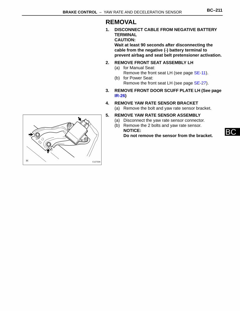
BRAKE CONTROL – YAW RATE AND DECELERATION SENSOR BC–211
BC
REMOVAL1. DISCONNECT CABLE FROM NEGATIVE BATTERY
TERMINALCAUTION:Wait at least 90 seconds after disconnecting the cable from the negative (-) battery terminal to prevent airbag and seat belt pretensioner activation.
2. REMOVE FRONT SEAT ASSEMBLY LH(a) for Manual Seat:
Remove the front seat LH (see page SE-11).(b) for Power Seat:
Remove the front seat LH (see page SE-27).
3. REMOVE FRONT DOOR SCUFF PLATE LH (See page IR-26)
4. REMOVE YAW RATE SENSOR BRACKET(a) Remove the bolt and yaw rate sensor bracket.
5. REMOVE YAW RATE SENSOR ASSEMBLY(a) Disconnect the yaw rate sensor connector.(b) Remove the 2 bolts and yaw rate sensor.
NOTICE:Do not remove the sensor from the bracket.
C127334
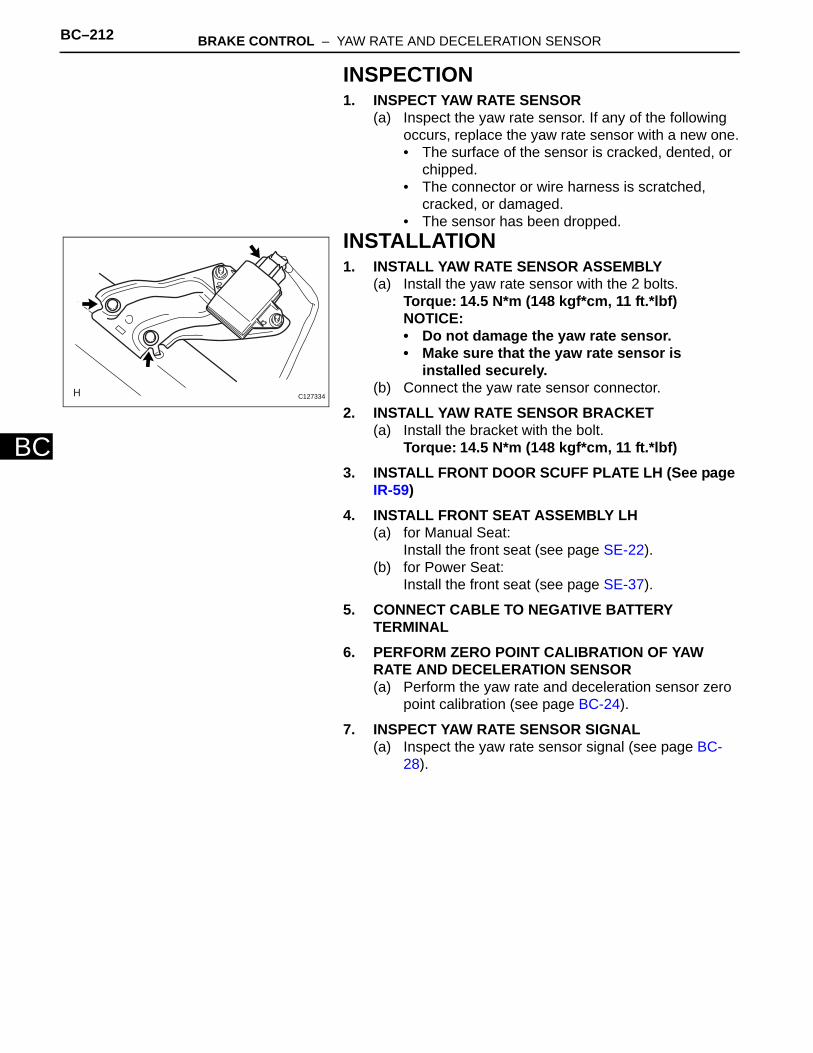
BC–212 BRAKE CONTROL – YAW RATE AND DECELERATION SENSOR
BC
INSPECTION1. INSPECT YAW RATE SENSOR
(a) Inspect the yaw rate sensor. If any of the following occurs, replace the yaw rate sensor with a new one.• The surface of the sensor is cracked, dented, or
chipped.• The connector or wire harness is scratched,
cracked, or damaged.• The sensor has been dropped.
INSTALLATION1. INSTALL YAW RATE SENSOR ASSEMBLY
(a) Install the yaw rate sensor with the 2 bolts.Torque: 14.5 N*m (148 kgf*cm, 11 ft.*lbf)NOTICE:• Do not damage the yaw rate sensor.• Make sure that the yaw rate sensor is
installed securely.(b) Connect the yaw rate sensor connector.
2. INSTALL YAW RATE SENSOR BRACKET(a) Install the bracket with the bolt.
Torque: 14.5 N*m (148 kgf*cm, 11 ft.*lbf)3. INSTALL FRONT DOOR SCUFF PLATE LH (See page
IR-59)4. INSTALL FRONT SEAT ASSEMBLY LH
(a) for Manual Seat:Install the front seat (see page SE-22).
(b) for Power Seat:Install the front seat (see page SE-37).
5. CONNECT CABLE TO NEGATIVE BATTERY TERMINAL
6. PERFORM ZERO POINT CALIBRATION OF YAW RATE AND DECELERATION SENSOR(a) Perform the yaw rate and deceleration sensor zero
point calibration (see page BC-24).
7. INSPECT YAW RATE SENSOR SIGNAL(a) Inspect the yaw rate sensor signal (see page BC-
28).
C127334

BRAKE CONTROL – STEERING ANGLE SENSOR BC–213
BC
BRAKEBRAKE CONTROLSTEERING ANGLE SENSORCOMPONENTS
SPIRAL CABLE SUB-ASSEMBLY
STEERING WHEEL ASSEMBLY
STEERING WHEEL ASSEMBLY
w/ Steering Pad Switch
STEERING COLUMN COVER
STEERING COLUMN COVER
: Specified torqueN*m (kgf*cm, ft.*lbf)
50 (510, 37)
STEERING ANGLE SENSOR
STEERING PAD ASSEMBLY
STEERING PAD ASSEMBLY
50 (510, 37)
C127336E01

BC–214 BRAKE CONTROL – STEERING ANGLE SENSOR
BC
REMOVAL1. PRECAUTION
CAUTION:Be sure to read the "PRECAUTION" thoroughly before servicing (see page RS-1).
2. DISCONNECT CABLE FROM NEGATIVE BATTERY TERMINALCAUTION:Wait at least 90 seconds after disconnecting the cable from the negative (-) battery terminal to prevent airbag and seat belt pretensioner activation.
3. PLACE FRONT WHEELS FACING STRAIGHT AHEAD4. REMOVE STEERING PAD ASSEMBLY (See page RS-
336)5. REMOVE STEERING WHEEL ASSEMBLY (See page
SR-12)6. REMOVE STEERING COLUMN COVER (See page
SR-12)7. REMOVE SPIRAL CABLE SUB-ASSEMBLY (See page
SR-13)8. REMOVE STEERING ANGLE SENSOR
(a) Detach the 6 claws and remove the sensor from the spiral cable.
C128529

BRAKE CONTROL – STEERING ANGLE SENSOR BC–215
BC
INSPECTION1. INSPECT STEERING ANGLE SENSOR
(a) Inspect the sensor. If any of the following occurs, replace the sensor with a new one:• The surface of the sensor is cracked, dented, or
chipped.• The connector or wire harness is scratched,
cracked, or damaged.• The sensor has been dropped.
INSTALLATION1. INSTALL STEERING ANGLE SENSOR
(a) Align the locating pins, attach the 6 claws and install the sensor to the spiral cable.
2. INSTALL SPIRAL CABLE SUB-ASSEMBLY (See page SR-20)
3. INSTALL STEERING COLUMN COVER (See page SR-20)
4. INSTALL STEERING WHEEL ASSEMBLY (See page SR-21)
5. INSTALL STEERING PAD ASSEMBLY (See page RS-336)
6. INSPECT STEERING WHEEL CENTER POINT7. CONNECT CABLE TO NEGATIVE BATTERY
TERMINALNOTICE:When reconnecting the cable to the negative (-) battery terminal after installing the steering angle sensor, check that the front tires and steering wheel are kept aligned straight ahead before and after connecting the cable to the negative (-) battery terminal.
8. INSPECT STEERING PAD ASSEMBLY (See page RS-337)
9. CHECK SRS WARNING LIGHT(a) Check the SRS warning light (see page RS-37).
C128529

BC–216 BRAKE CONTROL – BRAKE PEDAL LOAD SENSING SWITCH
BC
BRAKE PEDAL LOAD SENSING SWITCHON-VEHICLE INSPECTION1. INSPECT BRAKE PEDAL LOAD SENSING SWITCH
HINT:• Do not remove the brake pedal load sensing switch
from the brake pedal support.• When there is a malfunction in the brake pedal load
sensing switch, replace the brake pedal support.(a) Disconnect the brake pedal load sensing switch
connector.
(b) Measure the resistance of the switch.Standard resistance
If the value is not as specified, replace the brake pedal support assembly (see page BR-12).
Brake Pedal Load
Sensing Switch
Brake Pedal Support
Brake Pedal Released (ON)
Brake Pedal Depressed (OFF)
2 1
C129075E02
Tester Connection Condition Specified Condition
1 - 2 Brake pedal depressed Approx. 1 kΩ
1 - 2 Brake pedal released Approx. 213 Ω

BRAKE CONTROL – DOWNHILL ASSIST CONTROL SWITCH BC–217
BC
BRAKEBRAKE CONTROLDOWNHILL ASSIST CONTROL SWITCHCOMPONENTS
DOWNHILL ASSIST
CONTROL SWITCH
C129079E01
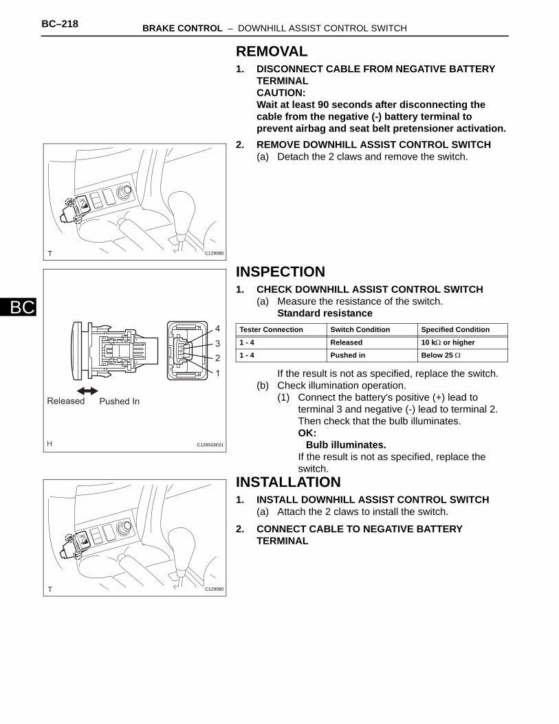
BC–218 BRAKE CONTROL – DOWNHILL ASSIST CONTROL SWITCH
BC
REMOVAL1. DISCONNECT CABLE FROM NEGATIVE BATTERY
TERMINALCAUTION:Wait at least 90 seconds after disconnecting the cable from the negative (-) battery terminal to prevent airbag and seat belt pretensioner activation.
2. REMOVE DOWNHILL ASSIST CONTROL SWITCH(a) Detach the 2 claws and remove the switch.
INSPECTION1. CHECK DOWNHILL ASSIST CONTROL SWITCH
(a) Measure the resistance of the switch.Standard resistance
If the result is not as specified, replace the switch.(b) Check illumination operation.
(1) Connect the battery's positive (+) lead to terminal 3 and negative (-) lead to terminal 2. Then check that the bulb illuminates.OK:
Bulb illuminates.If the result is not as specified, replace the switch.
INSTALLATION1. INSTALL DOWNHILL ASSIST CONTROL SWITCH
(a) Attach the 2 claws to install the switch.
2. CONNECT CABLE TO NEGATIVE BATTERY TERMINAL
C129080
Pushed InReleased
4
3
2
1
C128533E01
Tester Connection Switch Condition Specified Condition
1 - 4 Released 10 kΩ or higher
1 - 4 Pushed in Below 25 Ω
C129080
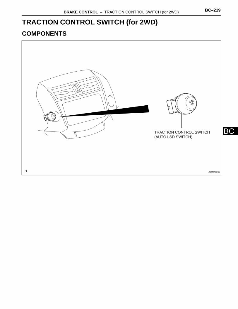
BRAKE CONTROL – TRACTION CONTROL SWITCH (for 2WD) BC–219
BC
BRAKEBRAKE CONTROLTRACTION CONTROL SWITCH (for 2WD)COMPONENTS
TRACTION CONTROL SWITCH
(AUTO LSD SWITCH)
C129078E01

BC–220 BRAKE CONTROL – TRACTION CONTROL SWITCH (for 2WD)
BC
REMOVAL1. DISCONNECT CABLE FROM NEGATIVE BATTERY
TERMINALCAUTION:Wait at least 90 seconds after disconnecting the cable from the negative (-) battery terminal to prevent airbag and seat belt pretensioner activation.
2. REMOVE TRACTION CONTROL SWITCH (AUTO LSD SWITCH)(a) Detach the 2 claws and remove the switch.
INSPECTION1. CHECK TRACTION CONTROL SWITCH (AUTO LSD
SWITCH)(a) Measure the resistance of the switch.
Standard resistance
If the result is not as specified, replace the switch.(b) Check illumination operation.
(1) Connect the battery's positive (+) lead to terminal 5 and negative (-) lead to terminal 4. Then check that the bulb illuminates.OK:
Bulb illuminates.If the result is not as specified, replace the switch.
INSTALLATION1. INSTALL TRACTION CONTROL SWITCH (AUTO LSD
SWITCH)(a) Attach the 2 claws to install the switch.
2. CONNECT CABLE TO NEGATIVE BATTERY TERMINAL
C129081
Released Pushed In
6
5
4
3
C128532E01
Tester Connection Switch Condition Specified Condition
3 - 6 Released 10 kΩ or higher
3 - 6 Pushed in Below 25 Ω
C129081

![CRUISE CONTROL & DRIVER ASSISTANCE DAS A · DAS PRECAUTIONS DAS-7 < PRECAUTION > [ADAS CONTROL UNIT] C D E F G H I J K L M B N P A PRECAUTION PRECAUTIONS Precaution for Supplemental](https://img.pdfslide.us/doc/110x75/5e179413ad625443225a6efa/cruise-control-driver-assistance-das-a-das-precautions-das-7-precaution.jpg)


![Monsoon precaution [aden pku]](https://img.pdfslide.us/doc/110x75/5883c5ca1a28ab5c378b77b5/monsoon-precaution-aden-pku.jpg)