Embed Size (px)
Citation preview
Attachment E
Registrant: Signature Flight Support
Date: 8/19/2014
Re: General Permit Registration Form for the Discharge of Stormwater and Dewatering from
Construction Activities
1
Stormwater Pollution Control Plan
(SPCP)
for the Construction Activities
Associated with the
Fuel Storage Facility Modifications Project
Bradley International Airport, Windsor Locks, CT
Prepared for:
Signature Flight Support Corporation
Prepared by:
Currier and Company, Inc.
August, 2014
2
SECTION 1: SPCP INTRODUCTION – FUEL STORAGE FACILITY MODIFICATIONS............................................................... 3
GENERAL............................................................................................................................................................................... 3
PLAN ORGANIZATION .............................................................................................................................................................. 3
REVISIONS TO THE SPCP .......................................................................................................................................................... 3
SECTION 2: SITE DESCRIPTION ........................................................................................................................................ 4
SITE DESCRIPTION NARRATIVE ................................................................................................................................................... 4
SITE PLAN ............................................................................................................................................................................. 4
SECTION 3: CONSTRUCTION SEQUENCING ...................................................................................................................... 5
SECTION 4: CONTROL MEASURES ................................................................................................................................... 6
EROSION AND SEDIMENT CONTROL ............................................................................................................................................ 6
Preserve and Control Soil .............................................................................................................................................. 6
Stabilization Structures ................................................................................................................................................. 6
Drainageways and Watercourses ................................................................................................................................. 7
Diversions ...................................................................................................................................................................... 7
Subsurface Drains .......................................................................................................................................................... 8
Energy Dissipators ......................................................................................................................................................... 8
Barriers and Filters ........................................................................................................................................................ 9
Tire Tracked Soils ........................................................................................................................................................... 9
Maintenance ................................................................................................................................................................. 9
DEWATERING WASTEWATER CONTROL MEASURES ...................................................................................................................... 12
SECTION 5: INSPECTIONS AND MONITORING ............................................................................................................... 12
PLAN IMPLEMENTATION INSPECTIONS ....................................................................................................................................... 12
ROUTINE INSPECTIONS ........................................................................................................................................................... 13
SECTION 6: CONTRACTORS ........................................................................................................................................... 13
GENERAL............................................................................................................................................................................. 13
CERTIFICATION STATEMENT..................................................................................................................................................... 13
SECTION 6: OTHER CONTROLS ...................................................................................................................................... 14
WASTE DISPOSAL.................................................................................................................................................................. 14
Material Handling ....................................................................................................................................................... 14
Solid and Liquid Waste Disposal .................................................................................................................................. 14
Hazardous Waste ........................................................................................................................................................ 14
Sanitary Waste ............................................................................................................................................................ 14
WASHOUT AREA ................................................................................................................................................................... 14
APPENDIX A: STORMWATER DISCHARGE REGISTRATION FORM AND GENERAL PERMIT FOR THE DISCHARGE OF
STORMWATER AND DEWATERING WASTEWATERS FROM CONSTRUCTION ACTIVITIES. ............................................... 16
APPENDIX B: INSPECTION REPORT FORM ..................................................................................................................... 18
APPENDIX C: CONTRACTOR IDENTIFICATION AND CERTIFICATION ............................................................................... 20
APPENDIX D: U.S. GEOLOGICAL SURVEY (USGS) QUADRANGLE MAP ........................................................................... 24
APPENDIX E: U.S. FISH AND WILDLIFE SERVICE (USFWS) MAP AND DRAWINGS ........................................................... 26
APPENDIX F: PROJECT DRAWINGS ............................................................................................................................... 28
3
Section 1: SPCP Introduction – Fuel Storage Facility Modifications
General Construction activities (including other land-disturbing activities) that disturb one acre or more are
regulated under the National Pollutant Discharge Elimination System (NPDES) stormwater program.
Under the authority of the Clean Water Act, the State of Connecticut General Permit for the Discharge
of Stormwater and Dewatering Wastewaters from Construction Activities (General Permit), dated
August 21, 2013 and effective on October 1, 2014, requires such activities to obtain coverage under the
General Permit, and as a requirement of coverage under the permit, prepare and implement a
Stormwater Pollution Control Plan (SPCP).
Signature Flight Support Corporation plans a construction project to address compliance issues at the
current Bradley International Airport Bulk Fuel Storage Facility. This project meets the definition of a
“construction activity” in accordance with the General Permit. A copy of the General Permit and
associated General Permit Registration Form are included in Appendix A.
This SPCP was prepared in accordance with the requirements of the General Permit. The purpose of this
plan is to avoid/mitigate pollution caused by soil erosion and sedimentation during construction. Erosion
and sedimentation control requirements are also shown on the Drawings for this project. During
construction, the construction contractor(s) shall be responsible for implementing all elements of the
erosion and sedimentation control measures as defined on the Drawings and in this SPCP. Throughout
the construction process, Signature or Signature’s agent and the Contractor shall periodically inspect all
erosion control measures. A copy of the inspection form to be used is provided in Appendix B. This
construction project will not be considered complete until all disturbed areas have been satisfactorily
stabilized, all erosion has been repaired, and all temporary erosion control measures have been
removed.
The general contractor and subcontractor(s) will be required to sign the certification statement provided
in Appendix C of this plan.
Plan Organization The SPCP is organized into six parts including a summary of the key provisions of the SPCP (Section 1.0); a site description (Section 2.0); a description of the construction sequence (Section 3.0); a description of the stormwater controls to be used to attain SPCP objectives (Section 4.0); inspection procedures (Section 5.0); and contractor requirements (Section 6.0).
Revisions to the SPCP In accordance with the requirements of the General Permit, the SPCP will be amended whenever:
(1) there is a change in contractors or subcontractors at the site; or
(2) there is a change in design, construction, operation or maintenance at the site which has the
potential for the discharge of pollutants to the waters of the State and which has not otherwise been
addressed in the SPCP; or
4
(3) if the actions required by the SPCP fail to prevent pollution. The Commissioner of the CTDEP may also
require to registrant to revise the SPCP if it does not meet one or more of the minimum requirements of
the General Permit.
Section 2: Site Description
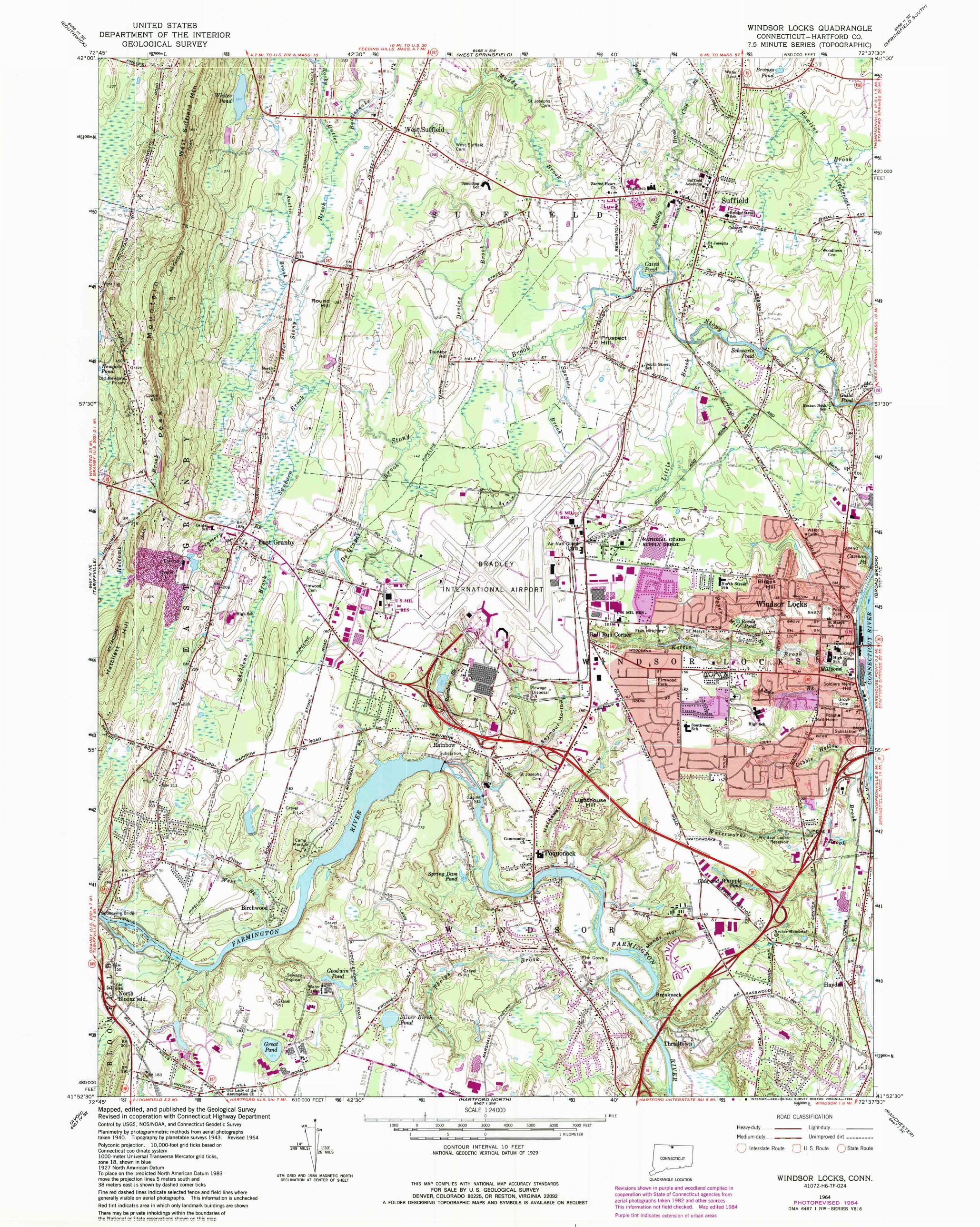
Site Description Narrative The Bradley International Airport (BDL) Bulk Fuel Storage Facility is located as indicated on the Site
Location Map (Appendix D). The Fuel Storage Facility Modification project is a renovation project of the
existing fuel storage facility at Bradley International Airport, which has been in continual operation since
1973. The approximate 3.5-acre parcel is located on property owned by the Connecticut Airport
Authority (CAA) and associated with Bradley International Airport (BDL) and within the Township of
Windsor Locks, CT. All Work for this project will be performed within the site's existing footprint, with all
areas of the site being subject to soil disturbance.
The Work shall include but not be limited to: new bottoms, ringwalls, and tank gauges for both ASTs, the
installation of an impervious liner system, and converting the UST from an off-spec tank to a contact
water tank. In addition, a new earthen dike will contain each AST within its own cell; this feature
improves containment by segregating a potential spill. The site Work includes modifications to the
existing bulk fuel facility and does not include any deforestation.
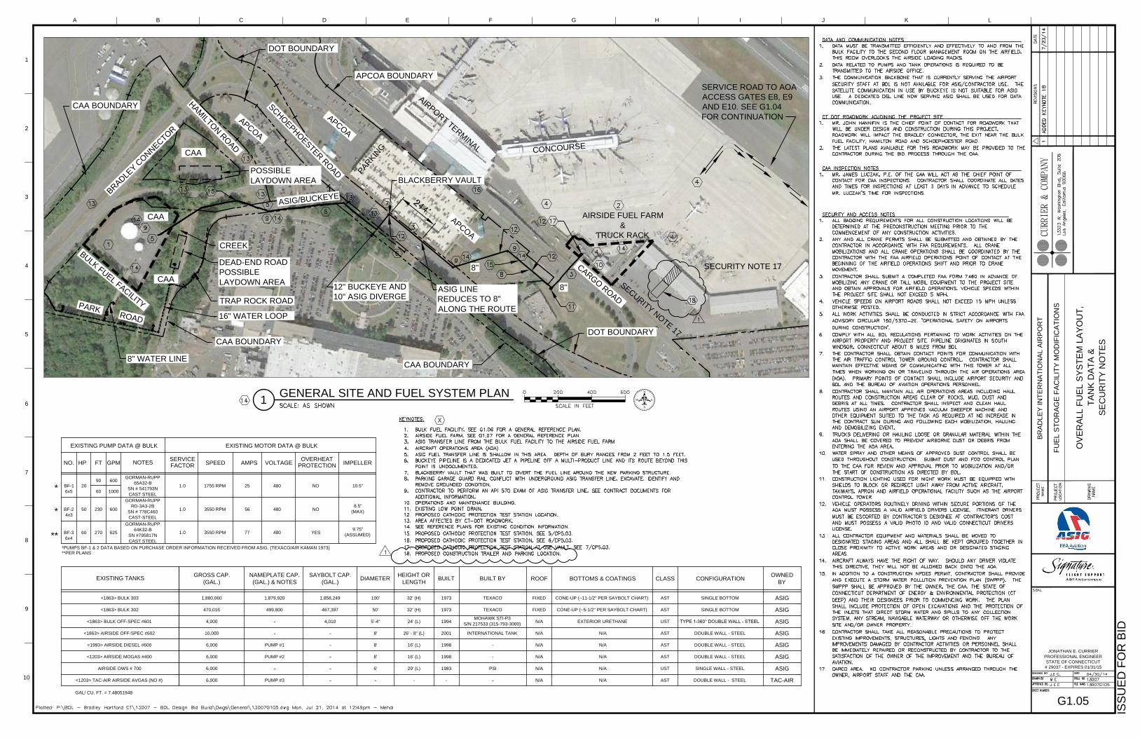
Access to the Bulk Storage Facility is via Park Rd, which intersects with Trap Rock Rd. The Bulk Storage
Facility consists of two large aboveground storage tanks (AST), one small underground storage tank
(UST), and other necessary fuel system equipment (filtration, pumps, piping, ect…) contained within a
dike area.
The immediate receiving waters around the site are Rainbow Brook to the Farmington River, with the
ultimate receiving water being the Connecticut River. There are no wetlands within the boundaries of
the site and there are no site-specific erosion or sediment control concerns and issues.
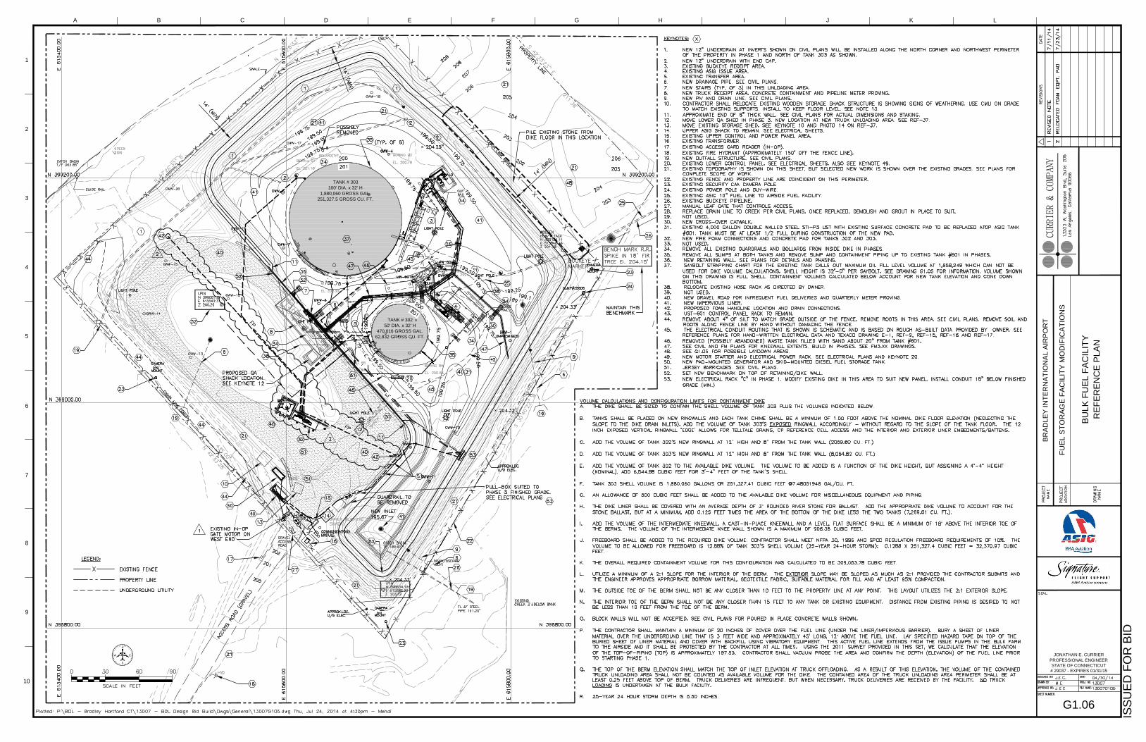
Site Plan A plan indicating the location and extents of the proposed construction activities is presented in the
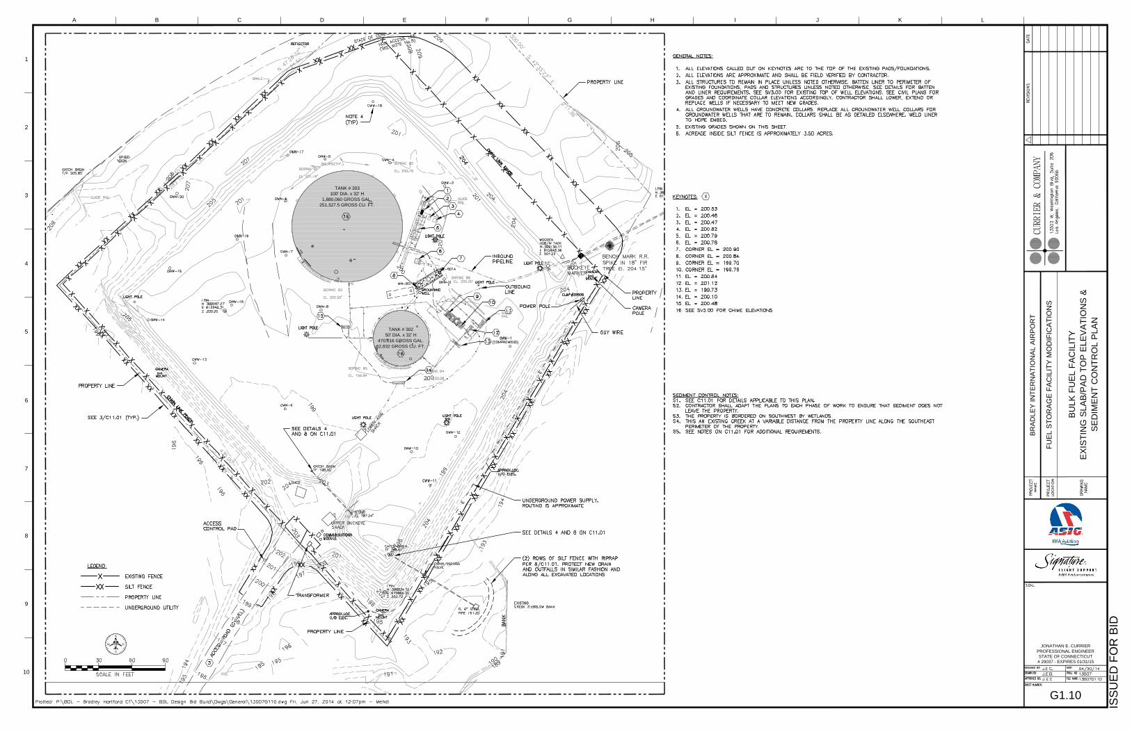
drawing G1.06 (Appendix F). The existing site conditions and grades are presented in drawing G1.10.
During phase 1 of the construction a 12” underdrain will be installed in the northern portion of the site
for the purpose of drying the site of standing water. The new outfall associated with the new underdrain
will be located along the northern portion of the northwest perimeter. A new dike is proposed, which
will utilize a 2:1 slope on both the exterior and interior dike walls. The interior of the dike will be lined
with an impervious HDPE liner system and graded such that all water collecting within the dike shall
drain to one of two strategically placed catch basins in the east and south corners of the dike along the
southwestern perimeter of the site. In addition, a new gravel road shall be constructed for the purposes
of fuel deliveries by truck. Generally, the area of the gravel roadway and surrounding area is pervious,
with one exception: the truck unloading area is impervious and drains into the dike area. Stormwater
5
runoff that is associated with this pervious area and new road will drain to a catch basin located within
the loop and then to the western perimeter of the site. Please see the drawings for the locations of the
underdrain and catch basin outfalls.
Erosion control measures during the construction activities were designed in accordance with the 2002
edition of the “Connecticut Guidelines for Soil and Sediment Control” as published by The Connecticut
Council on Soil and Water Conservation in cooperation with the Connecticut Department of
Environmental Protection. Installation details and detailed erosion and sediment control notes are
provided in the drawings. It is the intent of the owner to implement siltation fences, hay bales, and
other preventative measures at each outfall around the perimeter of the site throughout the duration of
construction. Additionally, the southeast perimeter of the site will be lined with hay bales to the extent
necessary to prevent stormwater runoff sheet flow from reaching the nearby Rainbow Brook.
Section 3: Construction Sequencing The Work at the BDL Bulk Fuel Facility shall be constructed in 3 phase:
Phase 1 (October 2014 to May 2015): Extend a new underdrain to relieve groundwater from beneath
the dike floor and liner within 30 days of mobilization, and revise drainage from the dike suited to the
subdivisions of the dike area (the number of point-discharges is limited to 4 as shown on the plans).
Modify piping on tank 302 and at Buckeye filtration to add direct fuel receipt capability to tank 302. Add
Buckeye communication for tank 302’s overfill protection using existing Morrison gauge at lower
electrical rack. Isolate tank 303 from the BDL fuel system. Receive by truck or pipeline and dispense fuel
from tank 302 only. Inspect flanged joints in service by x-raying all welds.
Upon installation of the new underdrain siltation fences and hay bales will be put in place in accordance
with the attached details.
Phase 2 (May 2015 to May 2016): Take tank 303 out of service, clean and perform all rework for tank
303 including ringwall, liner, cathodic protection, telltale, gauging, overfill protection, etc. Revise piping,
appurtenances and add control interfaces, and extend programmable logic controller communication to
the airside office of ASIG. Run raceway and conductors to new i/o cabinet and place it in the ASIG upper
shack near the gate. Re-use the off-spec sti-p3 UST in place while temporarily containing severed piping
and install fuel recovery system. Replace UST #601 concrete pad and access manways to allow the pad
to be sealed for containment. Take transfer pump bf-1 out of service. Leave the balance of the lower
control panel as-is until the next phase. Test and paint tank 303. Test all new controls. Verify manual
operation works as well. Hydrotest and inspect new piping, loop flush new fuel facility piping as much as
possible. Install portions of the semi-fixed foam connections to tank 303 and provide hand line near tank
303 for connection and service at the end of phase 3. Re-grading of the site shall begin at the southeast
perimeter, the northeast perimeter and the north corner while maintaining sufficient dike containment
volume.
Phase 3 (May 2016-September 2016): take tank 302 out of service, clean and perform all rework for
tank 302 including ringwall, liner, cathodic protection, telltale, gauging, overfill protection, bottom, etc.
6
Revise piping, appurtenances and add control interfaces, and extend interfaces to the plc
communication i/o cabinet. Install new liner for the cell surrounding tank 302. Hydrotest and inspect
new piping as directed.
Upon installation of new drainage catch basins and outfalls, siltation fences and hay bales will be put in
place in accordance with the attached details.
Section 4: Control Measures The following sections address the controls and measures to be implemented on the construction site to
minimize stormwater pollution to the waters of the state of Connecticut.
For a full list of control measures refer to the 2002 Connecticut Guidelines for Soil Erosion and Sediment
Control issued by The Connecticut Council on Soil and Water Conservation in Cooperation with the
Connecticut Department of Environmental Protection.
Erosion and Sediment Control The goal of this plan is to control erosion on the site and to control movement of sediment into adjacent
wetlands, watercourses or storm sewer systems. Note that erosion and sediment controls shall conform
to the requirements of the “Connecticut Guidelines for Soil Erosion and Sediment Control,” dated May
2002, which will hereafter be referred to as the Guidelines.
Preserve and Control Soil
Dust Control
To prevent the movement of dust from exposed soil surfaces, which may cause both off-site and on-site
damage, be a health hazard to humans, wildlife and plant life, or create a safety hazard by reducing
traffic visibility; exposed soil surfaces on unpaved travelways shall be periodically moistened by the
Contractor to keep the travelway damp and to minimize wind erosion.
Stabilization Structures
Structural practices shall be implemented to control the movement of sediment and minimize any discharge of pollutants from the site. The structural practices to be implemented during construction are as follows:
Retaining Wall
A portion of the new dike containment area will utilize a retaining wall, which shall be constructed
according to the attached plans.
Riprap
Riprap will be placed at each drainage outfall for the purposes of: protecting the soil surface form
erosive forces, slowing the velocity of runoff to enhance the potential of infiltration, and to stabilize
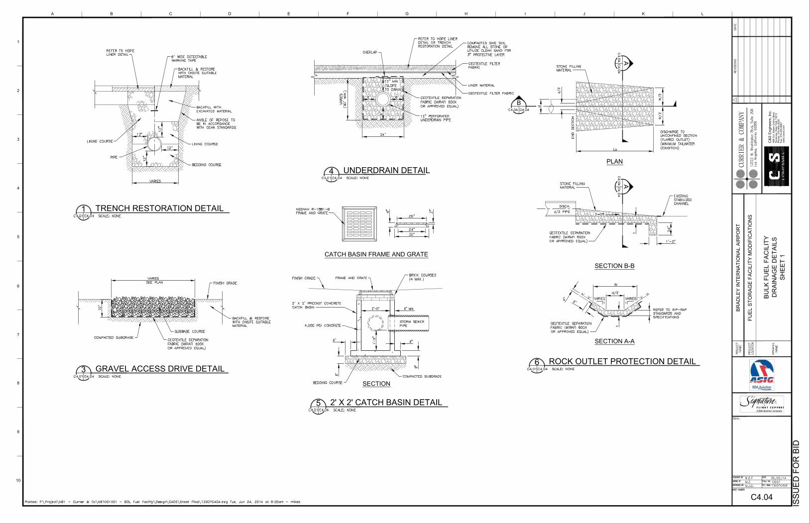
slopes with seepage problems. Please see drawings C4.09 and C11.01 for details.
7
Permanent Slope Drains
The new 12” HDPE underdrain outfall and the 3 drainage outfalls will employ permanent slope drains, to
convey water away from the site, while minimizing erosion. The drains shall be installed in conformance
with the attached plans. See details 1 and 4 of C4.04.
Drainageways and Watercourses
Permanent Lined Waterway
The new 12” HDPE underdrain outfall and the 3 drainage outfalls will employ permanent slope drains, to
convey water away from the site, while minimizing erosion. The drains shall be installed in conformance
with the attached plans. See details 1 and 4 of C4.04.
Diversions
Temporary Fill Berms
Temporary Fill Berms will be used to divert runoff from unprotected fill slopes during construction to a
stabilized outlet or sediment trap. Temporary fill berms shall not be used in excess of 5 days. For use
longer than 5 days the use of a temporary diversion shall be implemented.
Temporary Fill Berms shall be constructed such that:
1. The berm is at least 9 inches high with a base width of 3 feet.
2. The up slope side of the berm slope is no steeper than 3:1, the down slope side of the berm
slope is no steeper than 1:1, and the down slope toe of the berm is not closer than 2 feet from
the top of the fill slope.
3. The flow line controlled by the berm has a positive grade no steeper than 2%.
Temporary Diversions
Temporary Diversions shall be implemented when the intended use is 1 year or less, for the purposes of:
1. diverting sediment-laden runoff from a disturbed area to a sediment-trapping facility such as a
temporary sediment trap or sediment basin,
2. directing water originating from undisturbed areas away from areas where construction
activities are taking place, and
3. fragmenting disturbed areas thereby reducing the velocity and concentration of runoff.
No engineered design is required for a temporary diversion if the contributing drainage area is 1 acre or
less. If the contributing drainage area exceeds 1 acre and is 5 acres or less, design the temporary
diversion to the Permanent Diversion measure standards using the 2-year frequency storm as the design
storm.
Temporary Fill Berms shall be constructed such that:
1. The minimum height from the bottom of the channel to the top of the berm shall be as least 18
inches and the berm constructed of compacted material.
8
2. Side slopes shall be 3:1 or flatter inside and 1:1 or flatter outside. The top width of the berm
shall be 1 foot.
3. The flow line behind the berm shall have a positive grade. Channel grades flatter than 2%
require no stabilization. Channels with grades steeper than 2% require stabilization in
accordance with stabilization specifications found in the Permanent Diversion measure.
Temporary diversions shall be stabilized according to the duration of their intended use (see
Short Term Non-Living Soil Protection Functional Group).
4. The diverted runoff shall be diverted to a stable outlet or channel. If the diverted runoff is
expected to be carrying a sediment load, the runoff shall be released to sediment
impoundments.
Subsurface Drains
Subsurface Drains
The new 12” HDPE underdrain and the 4 drainage outfalls will employ permanent slope drains, to
convey water away from the site, while minimizing erosion. The drains shall be installed in conformance
with the attached plans. See details 1 and 4 of C4.04.
Energy Dissipators
Outlet Protection
Outlet protection measures shall be implemented to prevent scour at drainage outfalls and to minimize
the potential for downstream erosion by reducing the velocity of water flows. The rock outlet protection
shall be constructed in accordance with the attached plans. See detail 6/C4.04.
Stone Check Dam
A temporary stone check dam shall be placed across drainageways for the purposes of reducing the
velocity of runoff, and to temporarily pond runoff to allow sediments to settle out. The use of stone
check dams will be at the discretion of the Owner, Contractor, and Engineer.
No engineered design is required for a stone check dam if the contributing drainage area is 2 acres or
less and its intended use is shorter than 6 months. If the contributing drainage area is greater than 2
acres or its intended use is longer than 6 months, design the stone check dam according to generally
accepted engineering standards (e.g. National Engineering Handbook – Part 650, DOT Drainage Manual).
Additionally, the design shall contain construction standards and specifications required for
implementation and maintenance of the measure. For use of a stone check dam less than 1 year, design
the stone check dam to safely pass the peak flow expected from a 2-year frequency storm without
structural failure and adverse tailwater effects. For use of a stone check dam exceeding 1 year, design
the stone check dam to safely pass the peak flow expected from a 25-year frequency storm without
structural failure of the check dam and adverse tailwater effects.
9
Barriers and Filters
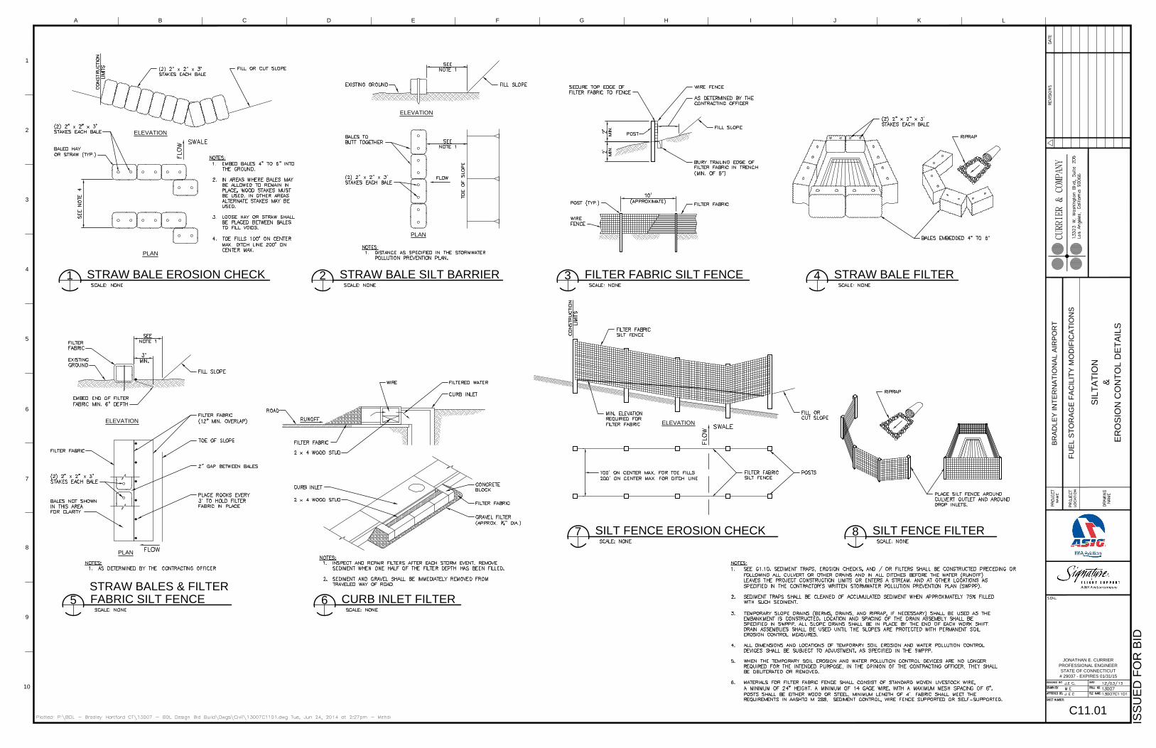
Hay Bale Barrier
Hay bale barriers shall be used a temporary sediment barrier for the purpose of: intercepting and
detaining sediment, decreasing the velocity of sheet flow, redirecting small volumes of water away from
erodible soils, and settling and assisting in the filtration of water discharged from construction activities.
This type of barrier shall be implemented where: the drainage area is less than 1 acre in size, protection
and effectiveness is less than 3 months, or where sedimentation will reduce the capacity of storm
drainage systems or adversely affect adjacent areas.
The hay bales shall be made of hay or straw with a minimum weight of 40lbs and a maximum weight of
120lbs. Stakes for anchoring the hay bales shall be a minimum of 36” in length and shall be made of
either hardwood with dimensions of at least 1.5” square or steel posts with a minimum weight of 0.5lbs
per linear foot. See details 1, 2, 4 and 5 on C11.01.
Geotextile Silt Fence
Geotextile siltation fences shall be implemented for the purposes of: intercepting and retaining
sediment for disturbed areas, and decreasing the velocity of sheet flows and low volume concentrated
flows. This type of barrier shall be implemented: where the drainage area is less than 1 acre in size, and
at drainage inlets and catch basins where sedimentation will reduce the capacity of the drainage system
or adversely affect the adjacent areas. This type of barrier is not to be used in areas where rock, frozen
ground or other hard surfaces prevent proper installation of the barrier, and is prohibited from use in
drainageways whose flow is supported by ground water discharge. Please see detail 3, 7, and 8 on
C4.04.
Tire Tracked Soils
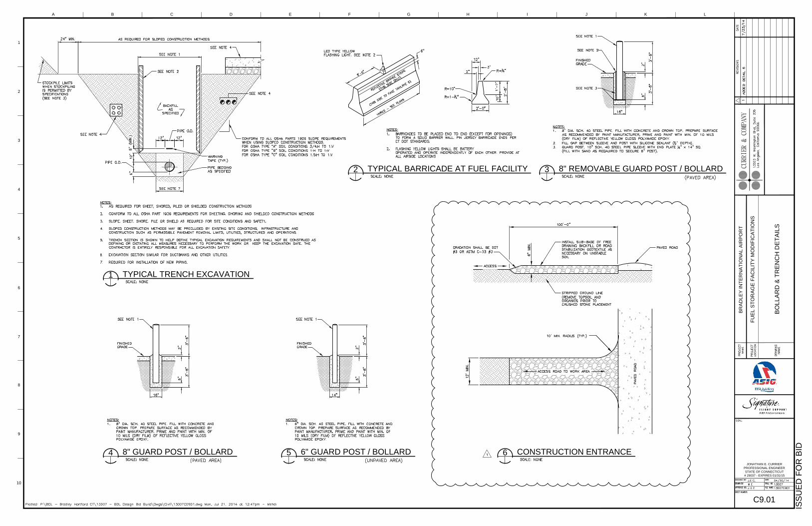
Construction Entrance
A stone stabilized pad shall be employed to reduce the tracking of sediment off site onto paved surfaces.
The Contractor shall place and maintain this pad at the entrance to the facility. Please see the
Construction Entrance detail on C9.01.
Maintenance
The erosion and sediment controls must be maintained in a condition that will protect the resource areas from pollution during site construction. The Contractor shall conduct the following maintenance to ensure that the proper performance of erosion and sediment control measures is maintained throughout construction.
Dust Control
Repeat application of dust control measures when fugitive.
Riprap
Riprap shall be inspected periodically to determine if high flows have caused scour beneath the
riprap or filter blanket or dislodged any of the riprap or filter blanket materials.
10
Permanent Drain Slopes
During construction of the permanent slope drain inspect associated temporary erosion and
sediment controls at least once a week and within 24 hours of the end of a storm with a rainfall
amount of 0.5 inch or greater for failure. Make repairs and adjustment to erosion controls as
needed.
Permanent Lined Waterway
Until the contributing drainage area is stabilized, inspect within 24 hours of the end of a storm with
a rainfall.
Temporary Fill Berms
Inspect the temporary fill berm and associated controls at the end of each work day to ensure the
criteria for installing the measure has been met. Determine if repair or modification of the berm and
associated measures are needed. Make modification and/or repairs as needed.
Temporary Diversions
When the temporary diversion is located within close proximity to ongoing construction activities,
inspect the temporary diversion at the end of each work day and immediately repair damages
caused by construction equipment. Otherwise inspect the temporary diversion and any associated
measures weekly or immediately after 0.5 inch of rain falls within a 24-hour period to determine
maintenance needs.
Repair the temporary diversion and any associated measures within 24 hours of observed failure.
Failure of the temporary diversion has occurred when the diversion had been damaged by either
construction equipment, erosion or siltation such that it no longer meets the criteria provided in the
engineered design (if any).
When repetitive failures occur at the same location, review conditions and limitation for use and
determine if additional measures are needed to reduce failure rates or if alternate measures are
indicated to replace the temporary diversion.
Subsurface Drain
Inspect the outlets to subsurface drains annually to ensure that they are free-flowing, not clogged
with sediment and the animal guards are in place. Keep the outlet clean and free of debris. Keep any
surface inlets open and free of sediment and other debris. Trees located too close to a subsurface
drain often clog the system with their roots. If a drain becomes clogged, relocate the drain or
remove the trees.
Outlet Protection
Inspect the completed structure annually and after each major rainfall for damage and
deterioration. Repair damages immediately.
Stone Check Dam
For temporary stone check dams, inspect stone check dams at least once a week and within 24
hours of the end of a storm with a rainfall amount of 0.5 inch or greater to determine maintenance
11
needs. Remove the sediment deposits when deposits reach approximately half the height of the
check dam. Replace or repair the check dam within 24 hours of observed failure. Failure of the check
dam has occurred when sediment fails to be retained because: stone has moved, soil has eroded
around or under the check dam reducing its functional capacity, or when trapped sediments are
overtopping the check dam.
Maintain the stone check dam until the contributing area is stabilized. After the contributing area is
stabilized, remove accumulated sediment. Stone check dams may be removed or graded into the
flow line of the channel over the area left disturbed by sediment removal. Grade so there are no
obstructions to water flow. If stone check dams are used in grass-lined channels which will be
mowed, remove all the stone or carefully grade out the stone to ensure it does not interfere with
mowing. Stabilize any disturbed soil that remains from check dam removal operations.
Hay Bale Barrier
Inspect the hay bale barrier at least once a week and within 24 hours of the end of a storm with a
rainfall amount of 0.5 inch or greater to determine maintenance needs. For dewatering operations,
inspect frequently before, during, and after pumping operations.
Remove the sediment deposits or install a secondary barrier upslope from the existing barrier when
sediment deposits reach approximately one half the height of the barrier.
Replace or repair the barrier within 24 hours of observed failure. Failure of the barrier has occurred
when sediment fails to be retained by the barrier because: the barrier has been overtopped,
undercut or bypassed by the runoff, the barrier has been moved out of position, or the hay bales
have deteriorated or have been damaged.
Maintain the hay bale barrier until the contributing area is stabilized. After the upslope areas have
been permanently stabilized, pull the stakes out of the hay bales. Unless otherwise required, no
removal or regrading of accumulated sediment is necessary. The hay bales may then be left in place
or broken up for ground cover.
Geotextile Silt Fence
Inspect the silt fence at least once a week and within 24 hours of the end of a storm with a rainfall
amount of 0.5 inch or greater to determine maintenance needs. When used for dewatering
operations, inspect frequently before, during and after pumping operations.
Remove the sediment deposits or, if room allows, install a secondary silt fence up slope of the
existing fence when sediment deposits reach approximately one half the height of the existing
fence. Replace or repair the fence within 24 hours of observed failure. Failure of the fence has
occurred when sediment fails to be retained by the fence because: the fence has been overtopped,
undercut or bypassed by the runoff, the fence has been moved out of position, or the geotextile has
decomposed or has been damaged.
12
Maintain the fence until the contributing area is stabilized. After the contributing area is stabilized
determine if sediment contained by the fence requires removal or regrading and stabilization. If the
depth is greater than or equal to 6 inches, regrading or removal of the accumulated sediment is
required. No removal or regrading is required if sediment depth is less than 6 inches.
Remove the fence by pulling up the support posts and cutting the geotextile at ground level.
Regrade or remove sediment as needed, and stabilize disturbed soils.
Construction Entrance
Maintain the entrance in a condition which will prevent tracking and washing of sediment onto
paved surfaces. Provide periodic top dressing with additional stone or additional length as
conditions demand. Repair any measures used to trap sediment as needed. Immediately remove all
sediment spilled, dropped, washed or tracked onto paved surfaces. Roads adjacent to a construction
site shall be left clean at the end of each day.
If the construction entrance is being properly maintained and the action of a vehicle traveling over
the stone pad is not sufficient to remove the majority of the sediment, then either (1) increase the
length of the construction entrance, (2) modify the construction access road surface, or (3) install
washing racks and associated settling area or similar devices before the vehicle enters a paved
surface.
Dewatering Wastewater Control Measures Should excavation dewatering become necessary for this project, there shall be no discharge directly into wetlands, watercourses, or storm sewer structures. Proper methods and devices shall be utilized to the extent permitted by law, such as pumping water into a temporary sedimentation trap, providing surge protection at the inlet and outlet of pumps, floating the intake of the pump, or other methods to minimize and retain the suspended solids. If a pumping operation causes turbidity in excess of the allowable limits, the operation shall cease until feasible means of controlling turbidity are determined and implemented.
For details and specifications on acceptable control measures for dewatering refer to the 2002 Connecticut Guidelines for Soil Erosion and Sediment Control issued by The Connecticut Council on Soil and Water Conservation in Cooperation with the Connecticut Department of Environmental Protection.
Section 5: Inspections and Monitoring
Plan Implementation Inspections Within the first 30 days following commencement of the construction activity on the site, the Contractor
shall contact: (1) the appropriate District; or (2) a qualified soil erosion and sediment control
professional or a qualified professional engineer to inspect the site. The site shall be inspected at least
once and no more than three times during the first 90 days to confirm compliance with the general
permit and proper initial implementation of all controls measures designated in the Plan for the site for
the initial phase of construction. For sites not inspected by District personnel, the following conditions
shall apply: is not an employee, as defined by the Internal Revenue Service in the Internal Revenue Code
13
of 1986, of the registrant, and has no ownership interest of any kind in the project for which the
registration is being submitted.
Routine Inspections Signature’s agent and/or qualified personnel provided by the Contractor shall inspect disturbed areas of the construction activity that have not been permanently stabilized, structural control measures, and locations where vehicles enter or exit the site at least once every seven calendar days and within 24 hours of the end of a storm that generated 0.1 inches during a twenty-four hour period. Where areas have been temporarily or finally stabilized, inspections shall be conducted at least once every month for three months. Disturbed areas and areas used for storage of materials that are exposed to precipitation shall be inspected for evidence of, or the potential for, pollutants entering the drainage system. Erosion and sediment control measures identified in the plan shall be observed to ensure that they are operating correctly. Where discharge locations or points are accessible, they shall be visually inspected to ascertain whether erosion control measures are effective in preventing significant impacts to receiving waters. Locations where vehicles enter or exit the site shall be inspected for evidence of off-site sediment tracking. Based on the results of the inspections, the description of potential sources and pollution prevention measures identified in this plan shall be revised as appropriate by Signature or its assigned agent as soon as practicable after such inspection. Such modifications shall provide for timely implementation of any changes to the site within 24 hours and implementation of any changes to the SPCP within 3 calendar days following the inspection. A report summarizing the scope of the inspection, name(s) and qualifications of personnel making the inspection, the date(s) of the inspection, major observations relating to the implementation of the SPCP, and actions taken shall be made and retained as part of the SPCP for at least three years after the date of inspection. The report shall be signed by Signature or its assigned agent. A blank copy of the inspection report is provided in Appendix B.
Section 6: Contractors
General All contractors and subcontractors who will perform Work on site that may reasonably be expected to cause or have the potential to cause pollution of the waters of the State of Connecticut are identified in Appendix C.
Certification Statement All contractors and subcontractors shall sign the certification included in Appendix C. All certifications shall be included in this Stormwater Pollution Control Plan.
14
Section 6: Other Controls
Waste Disposal
Material Handling
All construction materials that could potentially contamination stormwater (petroleum products,
solvents, concrete waste, paint, etc.) will be handled to minimize exposure to stormwater. Materials will
be kept in secure containers and be properly labeled, with copies of the Material Safety Data Sheets
(MSDS) maintained on-site.
Solid and Liquid Waste Disposal
Solid and liquid waste will be disposed of properly and in accordance with municipal disposal
requirements. All waste material will be stored in a secure container while awaiting their removal from
the Project site. The waste containers shall be inspected regularly to ensure their integrity. Additionally,
no solid or liquid wastes will be disposed of on-site, instead they shall be taken off-site for proper
disposal in accordance with municipal disposal requirements.
Hazardous Waste
Any hazardous waste material will be disposed of in the manner specified by the manufacturer and by
local, state, and federal regulations.
Sanitary Waste
The Contractor must comply with all federal, state, and local sanitary sewer, portable toilet, or septic
system regulations. The contractor shall provide sanitary facilities at the Project site throughout the
duration of construction activities and the sanitary facilities should be used by all construction personnel
and be serviced regularly. The Contractor shall coordinate with the Owner to determine the best
location for the sanitary facilities.
Washout Area If vehicle washing is required, the washout of applicators, containers, vehicles and equipment for
concrete, paint and other materials shall be conducted in a designated washout area within the
contained area. The Contractor shall coordinate with the Owner a designated washout area such that no
surface discharge of washout wastewaters form the area shall occur.
The washout area shall be contained and shall be located inside the existing dike and shall be an entirely
self-contained washout system. The designated washout area shall be clearly flagged off and shall only
be used for washing and conducting such activities.
In addition, dumping of liquid wastes in storm sewers or outfalls is prohibited. The Contractor shall
remove and dispose of hardened concrete waste consistent with practices developed for waste disposal.
At least once per week, the Contractor must inspect any containers or pits used for washout to ensure
structural integrity, adequate holding capacity, and to check for leaks or overflows. If there are signs of
leaks, holes or overflows in the containers or pits that could lead to a discharge, the Contractor shall
repair them prior to further use. For concrete washout areas, the Contractor shall remove hardened

15
concrete waste whenever the hardened concrete has accumulated to a height of ½ of the container or
pit or as necessary to avoid overflows.
16
Appendix A: Stormwater Discharge Registration Form and General
Permit for the Discharge of Stormwater and Dewatering Wastewaters
from Construction Activities.
17
Copy of Signed Stormwater Discharge Registration Form to Be Inserted Here

18
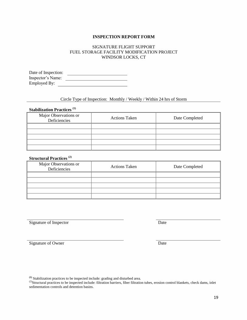
Appendix B: Inspection Report Form
19
INSPECTION REPORT FORM
SIGNATURE FLIGHT SUPPORT
FUEL STORAGE FACILITY MODIFICATION PROJECT
WINDSOR LOCKS, CT
Date of Inspection:
Inspector’s Name:
Employed By:
Circle Type of Inspection: Monthly / Weekly / Within 24 hrs of Storm
Stabilization Practices (1)
Major Observations or
Deficiencies Actions Taken Date Completed
Structural Practices (2)
Major Observations or
Deficiencies Actions Taken Date Completed
Signature of Inspector Date
Signature of Owner Date
(1) Stabilization practices to be inspected include: grading and disturbed area. (2)Structural practices to be inspected include: filtration barriers, fiber filtration tubes, erosion control blankets, check dams, inlet
sedimentation controls and detention basins.

20
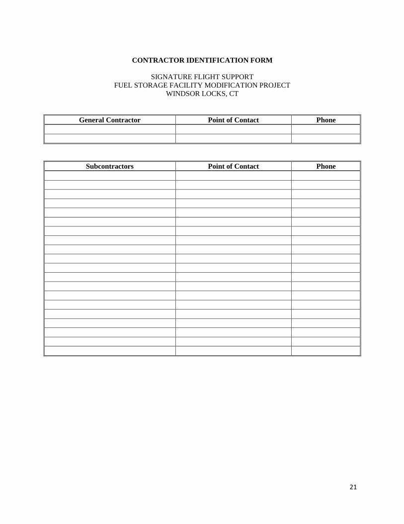
Appendix C: Contractor Identification and Certification
21
CONTRACTOR IDENTIFICATION FORM
SIGNATURE FLIGHT SUPPORT
FUEL STORAGE FACILITY MODIFICATION PROJECT
WINDSOR LOCKS, CT
General Contractor Point of Contact Phone
Subcontractors Point of Contact Phone
22
CERTIFICATION FORM
SIGNATURE FLIGHT SUPPORT
FUEL STORAGE FACILITY MODIFICATION PROJECT
WINDSOR LOCKS, CT
GENERAL CONTRACTOR
“I certify under penalty of law that I have read and understand the terms and conditions of the
General Permit for the Discharge of Stormwater and Dewatering Wastewaters from Construction
Activities. I understand that as a contractor or subcontractor at the site, I am authorized by this
general permit, and must comply with the terms and conditions of this general permit, including
but not limited to the requirements of the Stormwater Pollution Control Plan prepared for the
site.”
Signed: Date:
Printed Name:
Telephone:
Title:
Firm:
Address:
23
CERTIFICATION FORM
SIGNATURE FLIGHT SUPPORT
FUEL STORAGE FACILITY MODIFICATION PROJECT
WINDSOR LOCKS, CT
SUBCONTRACTOR
“I certify under penalty of law that I have read and understand the terms and conditions of the
General Permit for the Discharge of Stormwater and Dewatering Wastewaters from Construction
Activities. I understand that as a contractor or subcontractor at the site, I am authorized by this
general permit, and must comply with the terms and conditions of this general permit, including
but not limited to the requirements of the Stormwater Pollution Control Plan prepared for the
site.”
Signed: Date:
Printed Name:
Telephone:
Title:
Firm:
Address:

24
Appendix D: U.S. Geological Survey (USGS) Quadrangle Map
26
Appendix E: U.S. Fish and Wildlife Service (USFWS) Map and Drawings
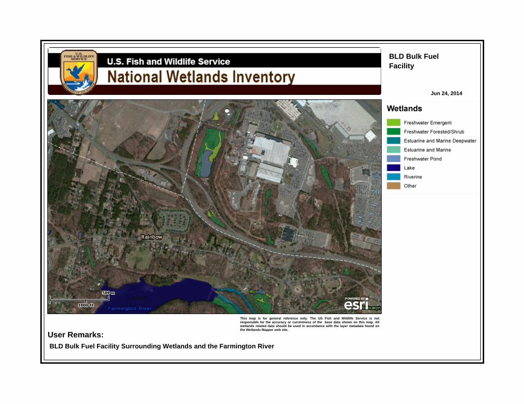
BLD Bulk FuelFacility
Jun 24, 2014
This map is for general reference only. The US Fish and Wildlife Service is notresponsible for the accuracy or currentness of the base data shown on this map. Allwetlands related data should be used in accordance with the layer metadata found onthe Wetlands Mapper web site.
User Remarks:BLD Bulk Fuel Facility Surrounding Wetlands and the Farmington River

28
Appendix F: Project Drawings
B
U
L
K
F
U
E
L
F
A
C
I
L
I
T
Y
P
A
R
K
CO
NC
OU
RS
E
A
I
R
P
O
R
T
T
E
R
M
I
N
A
L
BLACKBERRY VAULT
CREEK
DEAD-END ROAD
POSSIBLE
LAYDOWN AREA
TRAP ROCK ROAD
B
R
A
D
L
E
Y
C
O
N
N
E
C
T
O
R
H
A
M
I
L
T
O
N
R
O
A
D
S
C
H
O
E
P
H
O
E
S
T
E
R
R
O
A
D P
A
R
K
I
N
G
12" BUCKEYE AND
10" ASIG DIVERGE
AIRSIDE FUEL FARM
&
TRUCK RACK
C
A
R
G
O
R
O
A
D
AS
IG/B
UC
KE
YE
ASIG LINE
REDUCES TO 8"
ALONG THE ROUTE
R
O
A
D
8"
8"
POSSIBLE
LAYDOWN AREA
SECURITY NOTE 17
SERVICE ROAD TO AOA
ACCESS GATES E8, E9
AND E10. SEE G1.04
FOR CONTINUATION
S
E
C
U
R
I
T
Y
N
O
T
E
1
7
16" WATER LOOP
8" WATER LINE
A
P
C
O
A
A
P
C
O
A
CAA
CAA
CAA
DOT BOUNDARY
CAA BOUNDARY
DOT BOUNDARY
CAA BOUNDARY
CAA BOUNDARY
APCOA BOUNDARY
A
P
C
O
A
N
S
EW
BR
AD
LE
Y IN
TE
RN
AT
IO
NA
L A
IR
PO
RT
FU
EL S
TO
RA
GE
F
AC
ILIT
Y M
OD
IF
IC
AT
IO
NS
1
A B C D E F G H I J K L
2
3
4
5
6
8
9
10
7
JONATHAN E. CURRIER
PROFESSIONAL ENGINEER
STATE OF CONNECTICUT
# 29037 - EXPIRES 01/31/15
IS
SU
ED
F
OR
B
ID
G1.05
OV
ER
AL
L F
UE
L S
YS
TE
M L
AY
OU
T,
TA
NK
D
AT
A &
SE
CU
RIT
Y N
OT
ES
1
GENERAL SITE AND FUEL SYSTEM PLAN
<1863> BULK 303
DOUBLE WALL - STEEL
DOUBLE WALL - STEEL
DOUBLE WALL - STEEL
TYPE 1-360° DOUBLE WALL - STEEL
SINGLE BOTTOM
SINGLE BOTTOM
AST
UST
AST
AST
AST
CONE-UP (~11-1/2" PER SAYBOLT CHART)
CONE-UP (~5-1/2" PER SAYBOLT CHART)
EXTERIOR URETHANE
N/A
N/A
N/A
FIXED
FIXED
N/A
N/A
N/A
N/A
TEXACO
TEXACO
INTERNATIONAL TANK
1973
1973
1994
2001
1998
1998
32' (H)
32' (H)
24' (L)
26' - 8" (L)
16' (L)
16' (L)
100'
50'
5'-4"
8'
8'
8'
1,880,060
470,016
4,000
10,000
6,000
6,000
<1863> BULK 302
<1863> BULK OFF-SPEC #601
<1863> AIRSIDE OFF-SPEC #602
<1993> AIRSIDE DIESEL #600
<1203> AIRSIDE MOGAS #400
-
-
SINGLE WALL - STEELUSTN/AN/A198329' (L)6'6,000AIRSIDE OWS # 700 PSI
GPMNOTES
600
GORMAN-RUPP
65A32-B
SN # 541793N
CAST STEEL
GORMAN-RUPP
RD-3A3-2B
SN # 778C460
CAST-STEEL
GORMAN-RUPP
64K32-B
SN #795817N
CAST STEEL
625
FT
90
270
HP
20
50
60
NO.
EXISTING MOTOR DATA @ BULK
1,879,920
499,800
-
-
PUMP #1
PUMP #2
-
1,858,249
467,397
4,010
-
-
-
-
AST
SERVICE
1.0
1.0
1.0
1755 RPM
3550 RPM
3550 RPM
AMPS
25
56
77
VOLTAGE
480
480
480
PROTECTION
NO
NO
YES
SPEED
*PUMPS BF-1 & 2 DATA BASED ON PURCHASE ORDER INFORMATION RECEIVED FROM ASIG. (TEXACO/AIR KAMAN 1973)
FACTOR
OVERHEAT
EXISTING PUMP DATA @ BULK
*
ASIG
ASIG
ASIG
ASIG
ASIG
ASIG
ASIG
OWNED
BY
CONFIGURATIONCLASSBOTTOMS & COATINGSROOFBUILT BYBUILT
HEIGHT OR
LENGTH
DIAMETER
SAYBOLT CAP.
(GAL.)
NAMEPLATE CAP.
(GAL.) & NOTES
GROSS CAP.
(GAL.)
EXISTING TANKS
DOUBLE WALL - STEELASTN/AN/A--
-6,000<1203> TAC-AIR AIRSIDE AVGAS (NO #)
-PUMP #3
- TAC-AIR
*
GAL/ CU. FT. = 7.48051948
BF-1
6x5
BF-2
4x3
BF-3
6x4
IMPELLER
10.5"
8.5"
(MAX)
9.75"
(ASSUMED)
100060
600230
**
**PER PLANS
MOHAWK STI-P3
S/N 217533 (315-793-3000)
TANK # 302
50' DIA. x 32' H
470,016 GROSS GAL.
62,832 GROSS CU. FT.
TANK # 303
100' DIA. x 32' H
1,880,060 GROSS GAL.
251,327.5 GROSS CU. FT.
W
B
-
5
0
N
S
EW
G1.06
BU
LK
F
UE
L F
AC
IL
IT
Y
RE
FE
RE
NC
E P
LA
N
BR
AD
LE
Y IN
TE
RN
AT
IO
NA
L A
IR
PO
RT
FU
EL S
TO
RA
GE
F
AC
ILIT
Y M
OD
IF
IC
AT
IO
NS
1
A B C D E F G H I J K L
2
3
4
5
6
8
9
10
7
JONATHAN E. CURRIER
PROFESSIONAL ENGINEER
STATE OF CONNECTICUT
# 29037 - EXPIRES 01/31/15
IS
SU
ED
F
OR
B
ID
"
”
”
”
TANK # 302
50' DIA. x 32' H
470,016 GROSS GAL.
62,832 GROSS CU. FT.
TANK # 303
100' DIA. x 32' H
1,880,060 GROSS GAL.
251,327.5 GROSS CU. FT.
N
S
EW
G1.10
BU
LK
F
UE
L F
AC
IL
IT
Y
EX
IS
TIN
G S
LA
B/P
AD
T
OP
E
LE
VA
TIO
NS
&
SE
DIM
EN
T C
ON
TR
OL
P
LA
N
BR
AD
LE
Y IN
TE
RN
AT
IO
NA
L A
IR
PO
RT
FU
EL S
TO
RA
GE
F
AC
ILIT
Y M
OD
IF
IC
AT
IO
NS
1
A B C D E F G H I J K L
2
3
4
5
6
8
9
10
7
JONATHAN E. CURRIER
PROFESSIONAL ENGINEER
STATE OF CONNECTICUT
# 29037 - EXPIRES 01/31/15
IS
SU
ED
F
OR
B
ID
3 GRAVEL ACCESS DRIVE DETAIL
1 TRENCH RESTORATION DETAIL
4 UNDERDRAIN DETAIL
6 ROCK OUTLET PROTECTION DETAIL
PLAN
SECTION B-B
SECTION A-A
A
B
A
5 2' X 2' CATCH BASIN DETAIL
SECTION
CATCH BASIN FRAME AND GRATE
C4.04
BU
LK F
UE
L FA
CIL
ITY
DR
AIN
AG
E D
ETA
ILS
SH
EE
T 1
BR
AD
LEY
INTE
RN
ATI
ON
AL
AIR
PO
RT
FUE
L S
TOR
AG
E F
AC
ILIT
Y M
OD
IFIC
ATI
ON
S
ISS
UE
D F
OR
BID
1
A B C D E F G H I J K L
2
3
4
5
6
8
9
10
7
499
Col
. Eile
en C
ollin
s B
lvd.
Syr
acus
e, N
ew Y
ork
1321
2P
hone
: 315
-455
-200
0Fa
x: 3
15-4
55-9
667
ww
w.c
scos
.com
C&
S E
ngin
eers
, Inc
.
1
TYPICAL TRENCH EXCAVATION
4
8" GUARD POST / BOLLARD
3
8" REMOVABLE GUARD POST / BOLLARD
2
TYPICAL BARRICADE AT FUEL FACILITY
56" GUARD POST / BOLLARD
6
CONSTRUCTION ENTRANCE
C9.01
BO
LL
AR
D &
T
RE
NC
H D
ET
AIL
S
BR
AD
LE
Y IN
TE
RN
AT
IO
NA
L A
IR
PO
RT
FU
EL S
TO
RA
GE
F
AC
ILIT
Y M
OD
IF
IC
AT
IO
NS
1
A B C D E F G H I J K L
2
3
4
5
6
8
9
10
7
JONATHAN E. CURRIER
PROFESSIONAL ENGINEER
STATE OF CONNECTICUT
# 29037 - EXPIRES 01/31/15
IS
SU
ED
F
OR
B
ID
1
STRAW BALE EROSION CHECK
2
STRAW BALE SILT BARRIER
4
STRAW BALE FILTER
8
SILT FENCE FILTER
7
SILT FENCE EROSION CHECK
6
CURB INLET FILTER
3
FILTER FABRIC SILT FENCE
ELEVATION
PLAN
PLAN
ELEVATION
PLAN
ELEVATION
ELEVATION
STRAW BALES & FILTER
5FABRIC SILT FENCE
C11.01
SIL
TA
TIO
N
&
ER
OS
IO
N C
ON
TO
L D
ET
AIL
S
BR
AD
LE
Y IN
TE
RN
AT
IO
NA
L A
IR
PO
RT
FU
EL S
TO
RA
GE
F
AC
ILIT
Y M
OD
IF
IC
AT
IO
NS
1
A B C D E F G H I J K L
2
3
4
5
6
8
9
10
7
JONATHAN E. CURRIER
PROFESSIONAL ENGINEER
STATE OF CONNECTICUT
# 29037 - EXPIRES 01/31/15
IS
SU
ED
F
OR
B
ID