Embed Size (px)
Citation preview
F
0.600 3.061 0.600
4.262
7.431
1.579
0.979
5.038
3.098
3.070
0.400
0.813HALL
LOUNGEPLAYROOM
KITCHEN
AdjacentProperty
ExistingM/H
RWP
RWP
RWP
ExistingSVP
TD
ExistingB.I.G
WM
6.625
0.600
3.224
0.600
0.250
0.900
0.600
Thermal Block
Cavity FillHardcore
DPM 1200g
DPCGL DPM 500g
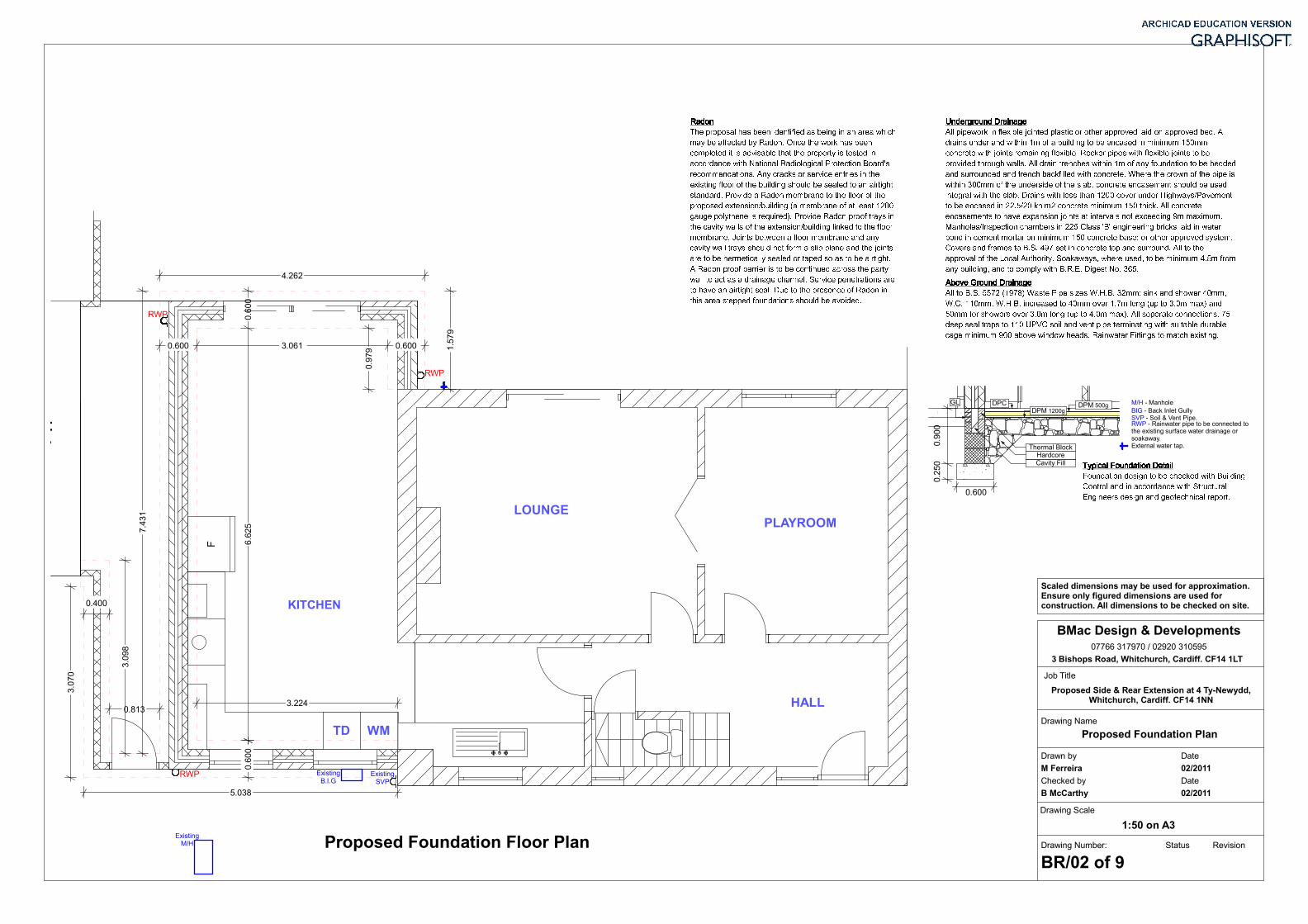
Proposed Side & Rear Extension at 4 Ty-Newydd,Whitchurch, Cardiff. CF14 1NN
Drawn by Date
M Ferreira 02/2011
Checked by Date
B McCarthy 02/2011
1:50 on A3
Drawing Name
Drawing Scale
Drawing Number: Status Revision
BR/02 of 9
Job Title
Proposed Foundation Plan
Proposed Foundation Floor Plan
RadonRadonRadonRadonThe proposal has been identified as being in an area whichmay be affected by Radon. Once the work has beencompleted it is advisable that the property is tested inaccordance with National Radiological Protection Board'srecommendations. Any cracks or service entries in theexisting floor of the building should be sealed to an airtightstandard. Provide a Radon membrane to the floor of theproposed extension/building (a membrane of at least 1200gauge polythene is required). Provide Radon proof trays inthe cavity walls of the extension/building linked to the floormembrane. Joints between a floor membrane and anycavity wall trays should not form a slip plane and the jointsare to be hermetically sealed or taped so as to be airtight.A Radon proof barrier is to be continued across the partywall to act as a drainage channel. Service penetrations areto have an airtight seal. Due to the presence of Radon inthis area stepped foundations should be avoided.
Underground DrainageUnderground DrainageUnderground DrainageUnderground DrainageAll pipework in flexible jointed plastic or other approved laid on approved bed. Alldrains under and within 1m of a building to be encased in minimum 150mmconcrete with joints remaining flexible. Rocker pipes with flexible joints to beprovided through walls. All drain trenches within 1m of any foundation to be beddedand surrounded and trench backfilled with concrete. Where the crown of the pipe iswithin 300mm of the underside of the slab, concrete encasement should be usedintegral with the slab. Drains with less than 1200 cover under Highways/Pavementto be encased in 22.5/20 kn m2 concrete minimum 150 thick. All concreteencasements to have expansion joints at intervals not exceeding 9m maximum.Manholes/Inspection chambers in 225 Class 'B' engineering bricks laid in waterbond in cement mortar on minimum 150 concrete base: or other approved system.Covers and frames to B.S. 497 set in concrete top and surround. All to theapproval of the Local Authority. Soakaways, where used, to be minimum 4.5m fromany building, and to comply with B.R.E. Digest No. 365.Above Ground DrainageAbove Ground DrainageAbove Ground DrainageAbove Ground DrainageAll to B.S. 5572 (1978) Waste Pipe sizes W.H.B. 32mm: sink and shower 40mm,W.C. 110mm, W.H.B. increased to 40mm over 1.7m long (up to 3.0m max) and50mm for showers over 3.0m long (up to 4.0m max). All seperate connections. 75deep seal traps to 110 UPVC soil and vent pipe terminating with suitable durablecage minimum 900 above window heads. Rainwater Fittings to match existing.
BMac Design & Developments07766 317970 / 02920 310595
3 Bishops Road, Whitchurch, Cardiff. CF14 1LT
Scaled dimensions may be used for approximation.Ensure only figured dimensions are used forconstruction. All dimensions to be checked on site.
BIG - Back Inlet GullySVP - Soil & Vent Pipe.
External water tap.
RWP - Rainwater pipe to be connected tothe existing surface water drainage orsoakaway.
M/H - ManholeTypical Foundation DetailTypical Foundation DetailTypical Foundation DetailTypical Foundation DetailFoundation design to be checked with BuildingControl and in accordance with StructuralEngineers design and geotechnical report.