Embed Size (px)
Citation preview
BPSK+BOC (5,2) SIGNAL SIMULATION AND GENERATION USING
MATLAB AND VECTOR SIGNAL GENERATOR
Presenter:ANSHUMAN SHARMA
Date : 10TH July, 2014MATLAB EXPO
Authors:ANSHUMAN SHARMAM R RAGHAVENDRAV RAJU SAGI
Presentation Outline
Motivation
Scope and Objective
BPSK+BOC modulation
Implementation
Simulated spectrum
Conclusion & future work
References
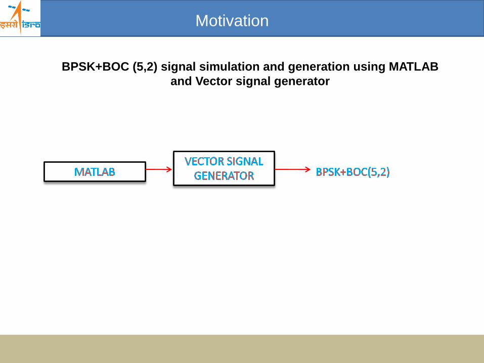
Motivation
BPSK+BOC (5,2) signal simulation and generation using MATLAB
and Vector signal generator
Scope and Objective
Scope : Simulation and generation of BPSK+BOC(5,2) signal at L5 and Sband.
Objective:
Generation of above signal to test Vector Signal Analyzer for followingparameters:
• Error Vector magnitude EVM
• Carrier Suppression
• Magnitude Error
• Gain Imbalance
• Quadrature Error
• The constellation points
BPSK+BOC modulation
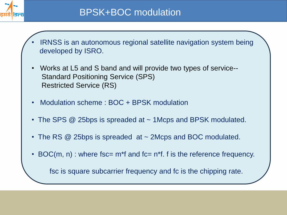
• IRNSS is an autonomous regional satellite navigation system being
developed by ISRO.
• Works at L5 and S band and will provide two types of service--
Standard Positioning Service (SPS)
Restricted Service (RS)
• Modulation scheme : BOC + BPSK modulation
• The SPS @ 25bps is spreaded at ~ 1Mcps and BPSK modulated.
• The RS @ 25bps is spreaded at ~ 2Mcps and BOC modulated.
• BOC(m, n) : where fsc= m*f and fc= n*f. f is the reference frequency.
fsc is square subcarrier frequency and fc is the chipping rate.
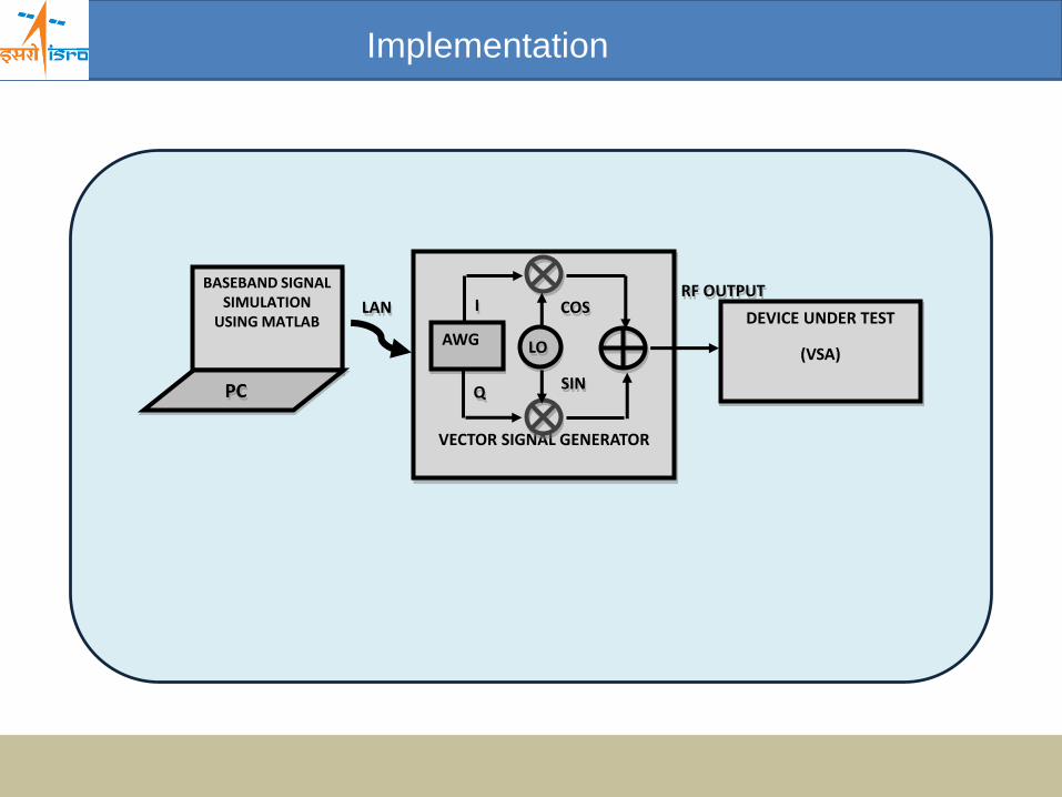
Implementation
BASEBAND SIGNAL SIMULATION
USING MATLAB
PC
VECTOR SIGNAL GENERATOR
AWG LO
COSDEVICE UNDER TEST
(VSA)
SIN
LAN I
Q
RF OUTPUT
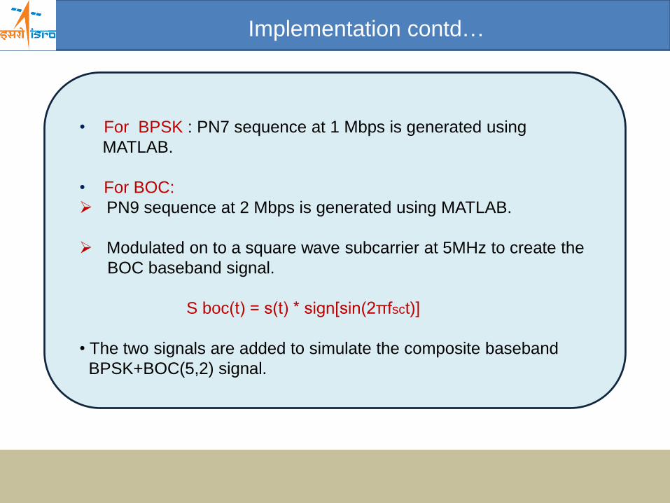
Implementation contd…
• For BPSK : PN7 sequence at 1 Mbps is generated using
MATLAB.
• For BOC:
PN9 sequence at 2 Mbps is generated using MATLAB.
Modulated on to a square wave subcarrier at 5MHz to create the
BOC baseband signal.
S boc(t) = s(t) * sign[sin(2πfsct)]
• The two signals are added to simulate the composite baseband
BPSK+BOC(5,2) signal.
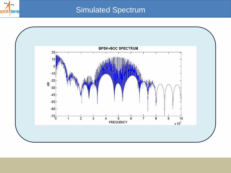
Simulated Spectrum
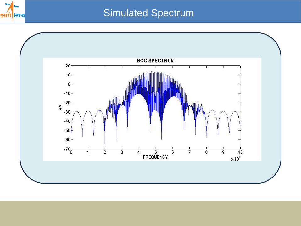
Simulated Spectrum
Conclusion and future work
This work was aimed at generation of BPSK+ BOC modulated composite signal.
The composite signal was generated using MATLAB and VSG.
Using this signal, Vector signal analyzer was successfully tested and qualified.
Same concept can be used for generating any type of Complex waveform.
References References
[1] R N Mutagi, “Pseudo noise sequences for engineers”, ELECTRONICS & COMMUNICATION
ENGINEERING JOURNAL, APRIL 1996.
[2] Emilie Rebeyrol, et al.,“Interplex Modulation for Navigation Systems at the L1 band" , ION NTM
2006, 18-20 January 2006, Monterey, CA
[3] Vladimir Kharisov, et al., “Optimal aligning of the sums of GNSS Navigation signals”, Jan/Feb
2012, www.insidegnss.com

THANK YOU