Embed Size (px)
Citation preview

BPMN Models
Enterprise Architect
User Guide Series
Author: Sparx Systems
Date: 30/06/2017
Version: 1.0
CREATED WITH

Table of Contents
BPMN Models 3Modeling with BPMN 2.0 5BPMN 2.0 Toolbox Pages 8
BPMN 2.0 Business Process Toolbox Pages 9BPMN 2.0 Choreography Toolbox Pages 12BPMN 2.0 Collaboration Toolbox Page 14BPMN 2.0 Conversation Toolbox Pages 17BPMN 2.0 Type Toolbox Page 19
BPMN 2.0 XML 21BPMN 1.0 and 1.1 Toolbox Pages 23Migrate BPMN 1.0 Model to BPMN 1.1 27Migrate BPMN 1.1 Model to BPMN 2.0 29
Change BPMN Element Appearance 31BPEL Models 37
BPEL 1.1 Model 38Create BPEL 1.1 Model Structure 40Model a BPEL 1.1 Process 42
Start Event 43Intermediate Event 45Activity 47Gateway 50End Event 52Sequence Flow 54Pool 55Assignment 56
Create BPEL 1.1 Web Service 58Generate BPEL 1.1 61
BPEL 2.0 Model 62Create BPEL 2.0 Model Structure 64Model a BPEL 2.0 Process 66
Start Event 67Intermediate Event 69Activity 71Gateway 73End Event 74Data Object 76Property 77Sequence Flow 78Pool 79Assignment 80
Create BPEL 2.0 Web Service Operation 82Generate BPEL 2.0 85
BPEL Model Validation 86

User Guide - BPMN Models 30 June, 2017
BPMN Models
If you need to model the activity of a business, capturing the behavior and the information flows within the organizationor system, you can do so using the Business Process Modeling Notation (BPMN). BPMN is specifically targeted at thebusiness modeling community and has a direct mapping to UML through BPMN Profiles integrated with the EnterpriseArchitect installer. Through use of these profiles, you can develop BPMN diagrams quickly and simply, and:
Maintain existing diagrams created in BPMN 1.0 format, and create new diagrams in BPMN 1.0·Create and maintain diagrams in the BPMN 1.1 and BPEL formats·Create and maintain diagrams in the BPMN 2.0 and BPEL formats·Migrate a BPMN 1.0 model (or part of a model) to BPMN 1.1, and a BPMN 1.1 model (or part of a model) to·BPMN 2.0
The Enterprise Architect installer for releases later than 8.0 provides you with separate versions of the MDG Technologyfor BPMN that support BPMN versions 1.0, 1.1 and 2.0, and BPEL.
Access
BPMN facilities are provided in the form of:
A BPMN diagram type, accessed through the 'New Diagram' dialog·BPMN pages in the Toolbox·BPMN element and relationship entries in the 'Toolbox Shortcut' menu and Quick Linker.·
Specifications of BPMN elements and relationships are defined by Tagged Values; for example, to define the Message,Timer and Default Path (/) symbols in this diagram:
BPMN Toolbox Pages
You can access the BPMN Toolbox pages through the 'Design > Diagram > Toolbox : 'Hamburger'' option; select the'BPMN 1.0', 'BPMN 1.1' or 'BPMN 2.0' option as appropriate.
You can also set BPMN as the active default technology to access the Toolbox pages directly.
(c) Sparx Systems 2015 - 2017 Page 3 of 87 Created with Enterprise Architect

User Guide - BPMN Models 30 June, 2017
Disable BPMN
If you prefer not to use BPMN in Enterprise Architect, you can disable it (and subsequently re-enable it) using the 'MDGTechnologies' dialog ('Configure > Technology > Manage').
(c) Sparx Systems 2015 - 2017 Page 4 of 87 Created with Enterprise Architect

User Guide - BPMN Models 30 June, 2017
Modeling with BPMN 2.0
Within Enterprise Architect, modeling with BPMN 2.0 is well supported, quick and simple. Use these notes to guide youas you create your business models.
Model Structure
A Business Process can be re-used by encapsulating the Pool (see Notes at the end of this topic). Once the Pool isencapsulated, a Business Process is created that is referenced by the Pool's Tagged Value processRef. At this point,elements that appeared in the Pool on the diagram will be nested in the referenced Business Process.
In Enterprise Architect, a BPMN Participant is represented by the Pool element. When you export your BPMN model toanother tool, in order to comply with the BPMN 2.0 specification the Pool is interpreted as a Participant in the XML. Onimport to Enterprise Architect, a Participant is interpreted as a Pool.
You can also use a Call Activity to reference another Business Process. As an illustration:
Drop an Activity element onto a diagram.1.
Open the element's 'Properties' dialog.2.
On the 'BPMN2.0' tab, click on the drop-down arrow in the Type field and select 'callProcessActivity'.3.
In the Activity Tagged Value list, click on the button at the right of the calledActivityRef Tagged Value, and4.browse for the appropriate Business Process.
Click on the browser OK button and on the 'Properties' dialog OK button.5.
Now, whenever you move an element onto this Call Activity, it will be nested in the referencing Business Process.
BPMN 2.0 Diagram Orientation
On a BPMN 2.0 diagram, you can set the flow orientation to horizontal or vertical, or none (the default).
To set or clear the orientation, right-click on the diagram background and click on 'Set Diagram Flow Direction'. Thenclick on either:
None (the default, no specific orientation set)·Horizontal (diagram flows across the page, Pool and Lane elements occupy the full width of the diagram), or·Vertical (diagram flows down the page, Pool and Lane elements occupy the full height of the diagram)·
BPMN 2.0 Sequence Flow and Message Flow Rules
Rules concerning the use of Sequence Flows and Message Flows, as defined in the BPMN 2.0 Specification anddescribed here, are implemented by the MDG Technology for BPMN 2.0.
These rules apply to Sequence Flows in relation to Events (Start, Intermediate and End), Activities (Task andSub-Process, for Processes), Choreography Activities (Choreography Task and Sub-Choreography, for Choreographies)and Gateways:
A Sequence Flow cannot cross a Pool boundary·An End Event cannot be the source element for a Sequence Flow·A Start Event cannot be the target element for a Sequence Flow·An Intermediate Event, if edge mounted on an Activity element, cannot be the source element for a Sequence Flow;·it cannot have incoming Sequence Flows
An Intermediate Event - if edge mounted on an Activity element and having the Tagged Value·
(c) Sparx Systems 2015 - 2017 Page 5 of 87 Created with Enterprise Architect

User Guide - BPMN Models 30 June, 2017
eventDefinition=Compensation, cannot be either the source or target element for a Sequence Flow
Objects within a Sub-Process cannot have a Sequence Flow relationship with objects outside the Sub-Process·A Sequence Flow cannot connect directly to a Pool·
These rules apply to Message Flows in relation to Events (Start, Intermediate and End), Activities (Task andSub-Process, for Processes), Choreography Activities (Choreography Task and Sub-Choreography, for Choreographies)and Pools:
Message Flows can be created from objects in one Pool to objects in another Pool; Message Flows can connect·directly to another Pool
A Message Flow can connect to Events (Start, Intermediate and End) only if they have the Tagged Value·eventDefinition=Message or eventDefinition=Multiple
A Start Event cannot be the source element for a Message Flow·An End Event cannot be the target element for a Message Flow·
Generate Call Activities
If you drag a BPMN 2.0 Global Task or Business Process element from the Project Browser onto a diagram, the systemcreates a Call Activity element containing Tagged Values appropriate to the type of element from which the Call Activitywas generated.
BPMN Validation
It is possible to validate your BPMN Model, either directly or as part of a simulation using a BPSim Configuration. Allerrors and warnings will be reported in the System Output window. Either:
Select a root Package containing a BPMN model, then select the 'Design > Package > Manage > Validation >·Validate Current Package' option, or
Within the BPSim Configuration, click on the Validate button to validate the model and configuration·
Notes
If a Pool element has the partnerEntity and partnerRole Tagged Values assigned, and an empty 'Name' field, the·element will display the Tagged Values
If a Lane element has the partitionElementRef Tagged Value assigned, and an empty 'Name' field, the element will·display the Tagged Value
When you create Lanes in a Pool, the first Lane will fill half the Pool and subsequent Lanes will fill the remaining·space
In the Project Browser, you can right-click on the diagram, Pool or Collaboration model and select 'Encapsulate·Process', which will move all the object's nested elements to a Business Process; elements placed inside theencapsulated element (during diagramming) will be moved to the Business Process
Encapsulating the diagram and the Collaboration/Choreography model give the same result; the action:· - Creates a 'main Pool' that the Collaboration Model will reference via the mainPool Tagged Value - Creates a Business Process that the 'main Pool' will reference via the processRef Tagged Value - Moves everything nested in or added to the Collaboration (minus pools and diagrams) to the new BusinessProcess
When you create a BPMN 2.0 diagram, the system prompts you to select whether or not to create an encapsulating·element for the diagram; that is, a: - Business Process for a Business Process diagram - Choreography Model for a Choreography diagram
(c) Sparx Systems 2015 - 2017 Page 6 of 87 Created with Enterprise Architect
User Guide - BPMN Models 30 June, 2017
- Collaboration Model for a Collaboration or BPEL diagram - Conversation Model for a Conversation diagram
When a Pool is dropped onto a BPMN diagram that is directly under a Package (and only in this circumstance), the·system prompts you to select whether or not to create a Collaboration Model for the Pool (rather than alwayscreating the Collaboration Model)
The two prompts above each have the checkbox 'Do not show this message again' that, if checked, blocks the prompt·from displaying and retains the current setting as the automatic action; you can reset the checkbox to unselectedusing the Reset BPMN Prompts button on the 'Diagram > Behavior' page of the 'Preferences' dialog
Encapsulating supports the re-use of processes, in that you can create links to Pools in other Collaboration models·for diagramming, and elements moved into them will be placed in the same Business Process (since the Poolrepresents a Process)
(c) Sparx Systems 2015 - 2017 Page 7 of 87 Created with Enterprise Architect
User Guide - BPMN Models 30 June, 2017
BPMN 2.0 Toolbox Pages
You can create BPMN elements and relationships on diagrams in BPMN 2.0 and BPEL formats using the BPMN 2.0pages of the Diagram Toolbox.
Access
Use any of the methods outlined here to display the Diagram Toolbox.
On the Diagram Toolbox, click on the More tools button and select 'BPMN 2.0'.
Ribbon Design > Diagram > Toolbox
Keyboard Shortcuts Alt+5
Other Click the icon on the Diagram caption bar to display the Diagram Toolbox
Diagram Type Toolboxes
Enterprise Architect provides a set of pages for each of these BPMN 2.0 diagram types:
Diagram Type
Business Process - contains the constructs needed to build Business Process models.
Choreography - contains the constructs needed to build Choreography models.
Collaboration - contains the constructs required to build Collaboration models.
Conversation - contains the constructs needed to build Conversation models.
Types - contains the constructs common to all BPMN 2.0 diagrams.
(c) Sparx Systems 2015 - 2017 Page 8 of 87 Created with Enterprise Architect

User Guide - BPMN Models 30 June, 2017
BPMN 2.0 Business Process Toolbox Pages
To create BPMN elements and relationships on business process diagrams in either BPMN 2.0 or BPEL formats, you canuse the 'BPMN 2.0 Business Process' pages of the Diagram Toolbox.
Access
Use any of the methods outlined here to display the Diagram Toolbox.
On the Diagram Toolbox, click on the More tools button then select 'BPMN 2.0 | BPMN 2.0 Business Process'.
Ribbon Design > Diagram > Toolbox : More Tools > BPMN 2.0 > BPMN 2.0 BusinessProcess
Keyboard Shortcuts Alt+5 : | BPMN 2.0 | BPMN 2.0 Business Process
Other Click the icon on the Diagram caption bar to display the Diagram Toolbox, then
| BPMN 2.0 | BPMN 2.0 Business Process
BPMN 2.0 Business Process Elements
Item Use to
Business Process Extend a composite Activity that defines a business process.
BPEL Define the behavior of an executable or abstract business process.
Activity Represent work that is performed within a Business Process. An Activity can bemodeled as a:
Sub-Process - a compound Activity that is defined as a flow of other BPMN·2.0 elements or
Task - an atomic Activity that cannot be broken down into a smaller unit·As a sub-process, the Activity can be made a composite element that links to a childdiagram containing the flow of other BPMN elements.
A BPMN Activity is initially created on a diagram with the name centered at thetop. If you drag elements onto the Activity the name can be obscured, so the systemautomatically moves the name into the top-left corner out of the way. You can alsocontrol this movement manually, by right-clicking on the element and selecting the'Is Expanded' option to toggle the setting.
Global Task Define a task or activity performed in the top-level process, at a higher level ofexecution.
Data Object Provide or store the information for an Activity.
Data Store Represent a mechanism for an Activity to retrieve or update stored information.
(c) Sparx Systems 2015 - 2017 Page 9 of 87 Created with Enterprise Architect

User Guide - BPMN Models 30 June, 2017
Start Event Define the initiating event in a process.
Elements of this type cannot be edge-mounted on other elements.
Intermediate Event Define an intermediate event in a process.
Elements of this type can only be edge-mounted on Activity elements.
End Event Define the terminating event in a process.
Elements of this type cannot be edge-mounted on other elements.
Gateway Define a decision point in a business process.
If a condition is true then processing continues one way; if false, then another.
Pool Extend a Partition element to logically organize an Activity.
Lane Extend a Partition element to subdivide a Pool.
Message Represent the contents of a communication between two elements.
Group Extend a Boundary element to group other elements.
Text Annotation Create a comment.
BPMN 2.0 BusinessProcess Connectors
Sequence Flow
Use to: Extend a Control Flow relationship to define the flow of activity.
Association Link the information and Artifacts with BPMN graphic elements.
Message Flow Extend a Control Flow relationship to define the flow of communications in theprocess.
Data Association Move data between Data Objects, Data Store, Properties and Activities, Processes.
Conversation Link Connect a Conversation Node with a Pool, in either direction.
BPMN 2.0 Business Process Connectors
Item Use to
Sequence Flow Sequence Flow
Use to: Extend a Control Flow relationship to define the flow of activity.
Association Link the information and Artifacts with BPMN graphic elements.
Message Flow Extend a Control Flow relationship to define the flow of communications in theprocess.
Data Association Move data between Data Objects, Data Store, Properties and Activities, Processes.
(c) Sparx Systems 2015 - 2017 Page 10 of 87 Created with Enterprise Architect

User Guide - BPMN Models 30 June, 2017
Conversation Link Connect a Conversation Node with a Pool, in either direction.
Example BPMN 2.0 Business Process Diagram
Notes
The appearance and specification of many elements and connectors are defined by Tagged Values·
(c) Sparx Systems 2015 - 2017 Page 11 of 87 Created with Enterprise Architect
User Guide - BPMN Models 30 June, 2017
BPMN 2.0 Choreography Toolbox Pages
To create BPMN elements and relationships on Choreography diagrams in either BPMN 2.0 or BPEL formats, you canuse the BPMN 2.0 Choreography pages of the Diagram Toolbox.
Access
Use any of the methods outlined here to display the Diagram Toolbox.
On the Diagram Toolbox, click on the More tools button then select 'BPMN 2.0 | BPMN 2.0 Choreography'.
Ribbon Design > Diagram > Toolbox : More tools | BPMN 2.0 | BPMN 2.0 Choreography
Keyboard Shortcuts Alt+5 : More tools | BPMN 2.0 | BPMN 2.0 Choreography
Other Click the icon on the Diagram caption bar to display the Diagram Toolbox, then
More tools | BPMN 2.0 | BPMN 2.0 Choreography
BPMN 2.0 Chorography Elements
Item Use to
Choreography Model Extend a composite Activity that defines a Choreography process.
Choreography Extend an Activity element to represent a process unit of information exchangebetween elements.
Start Event Define the initiating event in a process.
Elements of this type cannot be edge-mounted on other elements.
Intermediate Event Define an intermediate event in a process.
Elements of this type can only be edge-mounted on Activity elements.
End Event Define the terminating event in a process.
Elements of this type cannot be edge-mounted on other elements.
Gateway Define a decision point in a business process.
If a condition is true then processing continues one way; if false, then another.
Message Represent the contents of a communication between two elements.
Pool Extend a Partition element to logically organize an Activity.
Text Annotation Create a comment.
(c) Sparx Systems 2015 - 2017 Page 12 of 87 Created with Enterprise Architect

User Guide - BPMN Models 30 June, 2017
BPMN 2.0 Chorography Connectors
Item Use to
Sequence Flow Define the order of activity in a Choreography.
Association Link the information and Artifacts with BPMN graphic elements.
Message Flow Extend a Control Flow relationship to define the flow of communications in theprocess.
Example BPMN 2.0 Choreography Diagram
Notes
The appearance and specification of some elements and connectors are defined by Tagged Values·
(c) Sparx Systems 2015 - 2017 Page 13 of 87 Created with Enterprise Architect

User Guide - BPMN Models 30 June, 2017
BPMN 2.0 Collaboration Toolbox Page
To create BPMN elements and relationships on Collaboration diagrams in either BPMN 2.0 or BPEL formats, you canuse the 'BPMN 2.0 Collaboration' pages of the Diagram Toolbox.
Access
Use any of the methods outlined here to display the Diagram Toolbox.
On the Diagram Toolbox, click on the More tools button then select 'BPMN 2.0 | BPMN 2.0 Collaboration'.
Ribbon Design > Diagram > Toolbox : More tools > BPMN 2.0 > BPMN 2.0 Collaboration
Keyboard Shortcuts Alt+5 : More tools | BPMN 2.0 | BPMN 2.0 Collaboration
Other Click the icon on the Diagram caption bar to display the Diagram Toolbox, then
More tools | BPMN 2.0 | BPMN 2.0 Collaboration
BPMN 2.0 Collaboration Elements
Item Use to
Collaboration Model Extend a composite Activity that defines a Collaboration process.
Pool Extend a Partition element to logically organize an Activity.
Lane Extend a Partition element to subdivide a Pool.
Conversation Extend a Class element to group a set of Message Flows based on a certain concept.
Start Event Define the initiating event in a process.
Elements of this type cannot be edge-mounted on other elements.
Intermediate Event Define an intermediate event in a process.
Elements of this type can only be edge-mounted on Activity elements.
End Event Define the terminating event in a process.
Elements of this type cannot be edge-mounted on other elements.
Gateway Define a decision point in a business process.
If a condition is true then processing continues one way; if false, then another.
Activity Represents work that is performed within a Business Process. An Activity can bemodeled as a:
Sub-Process - a compound Activity that is defined as a flow of other BPMN·2.0 elements or
(c) Sparx Systems 2015 - 2017 Page 14 of 87 Created with Enterprise Architect

User Guide - BPMN Models 30 June, 2017
Task - an atomic Activity that cannot be broken down into a smaller unit·
As a sub-process, the Activity can be made a composite element that links to a childdiagram containing the flow of other BPMN elements.
Data Object Provide or store the information for an Activity.
Data Store Represent a mechanism for an Activity to retrieve or update stored information.
Choreography Extend an Activity element to represent a process unit of information exchangebetween elements.
Group Extend a Boundary element to group other elements.
Text Annotation Create a comment.
BPMN 2.0 Collaboration Connectors
Item Use to
Message Flow Extend a Control Flow relationship to define the flow of communications in theprocess.
Conversation Link Connect a Conversation Node to or from an element.
Sequence Flow Extend a Control Flow relationship to define the flow of activity.
Association Link the information and artifacts with BPMN graphic elements.
Example BPMN 2.0 Collaboration Diagram
(c) Sparx Systems 2015 - 2017 Page 15 of 87 Created with Enterprise Architect

User Guide - BPMN Models 30 June, 2017
Notes
The appearance and specification of some elements and connectors are defined by Tagged Values·
(c) Sparx Systems 2015 - 2017 Page 16 of 87 Created with Enterprise Architect

User Guide - BPMN Models 30 June, 2017
BPMN 2.0 Conversation Toolbox Pages
To create BPMN elements and relationships on Conversation diagrams in either BPMN 2.0 or BPEL formats, you canuse the BPMN 2.0 Conversation pages of the Diagram Toolbox.
Access
Use any of the methods outlined here to display the Diagram Toolbox.
On the Diagram Toolbox, click on the More tools button then select 'BPMN 2.0 | BPMN 2.0 Business Process'.
Ribbon Design > Diagram > Toolbox : More tools > BPMN 2.0 > BPMN 2.0 Conversation
Keyboard Shortcuts Alt+5 : More tools | BPMN 2.0 | BPMN 2.0 Conversation
Other Click the icon on the Diagram caption bar to display the Diagram Toolbox, then
More tools | BPMN 2.0 | BPMN 2.0 Conversation
BPMN 2.0 Conversation Elements
Item Use to
Conversation Model Extend a composite Activity that defines the logical relationship of Messageexchanges between two or more business entities.
Conversation Extend a Class element to group a set of Message Flows together based on a certainconcept.
Pool Extend a Partition element to logically organize an Activity.
Activity Represents work that is performed within a Business Process. An Activity can bemodeled as a:
Sub-Process - a compound Activity that is defined as a flow of other BPMN·2.0 elements or
Task - an atomic Activity that cannot be broken down into a smaller unit·
As a sub-process, the Activity can be made a composite element that links to a childdiagram containing the flow of other BPMN elements.
Start Event Define the initiating event in a process.
Elements of this type cannot be edge-mounted on other elements.
Intermediate Event Define an intermediate event in a process.
Elements of this type can only be edge-mounted on Activity elements.
End Event Define the terminating event in a process.
(c) Sparx Systems 2015 - 2017 Page 17 of 87 Created with Enterprise Architect
User Guide - BPMN Models 30 June, 2017
Elements of this type cannot be edge-mounted on other elements.
Gateway Define a decision point in a business process.
If a condition is true then processing continues one way; if false, then another.
Text Annotation Create a comment.
BPMN 2.0 Conversation Connectors
Item Use to
Conversation Link Connect a Conversation Node to a Pool element, in either direction.
Either the source or target element for a Conversation Link must be a ConversationNode element.
Message Flow Extend a Control Flow relationship to define the flow of communications in theprocess.
Sequence Flow Extend a Control Flow relationship to define the flow of activity.
Association Link the information and artifacts with BPMN graphic elements.
Notes
The appearance and specification of some elements and connectors are defined by Tagged Values·
(c) Sparx Systems 2015 - 2017 Page 18 of 87 Created with Enterprise Architect

User Guide - BPMN Models 30 June, 2017
BPMN 2.0 Type Toolbox Page
When you are working on a BPMN 2.0 diagram, you can also create a range of elements and connectors that are commonto all of the BPMN 2.0 diagram types, by dragging them from the BPMN 2.0 Types page of the Diagram Toolbox. The'BPMN 2.0 Types' toolbox page is common to all of the BPMN 2.0 toolboxes.
Access
Use any of the methods outlined here to display the Diagram Toolbox.
On the Diagram Toolbox, click on the More tools button then select 'BPMN 2.0 | BPMN 2.0 <any diagram type>'.
Ribbon Design > Diagram > Toolbox : More Tools > BPMN 2.0 > BPMN 2.0 <anydiagram type>
Keyboard Shortcuts Alt+5 : 'Hamburger' icon | BPMN 2.0 | BPMN 2.0 <any diagram type>
Other Click the icon on the Diagram caption bar to display the Diagram Toolbox, then
> BPMN 2.0 > BPMN 2.0 <any diagram type>
BPMN 2.0 Types
These items define the non-graphic elements or properties (Tagged Values) of the Core BPMN 2.0 graphic elements.
Assignment·CorrelationKey·CorrelationProperty·CorrelationPropertyBinding·CorrelationPropertyRetrievalExpression·CorrelationSubscription·Category·CategoryValue·ComplexBehaviorDefinition·ItemDefinition·Error·Escalation·Signal·IOSpecification·InputSet·OutputSet·InputOutputBinding·Interface·Endpoint·Operation·
(c) Sparx Systems 2015 - 2017 Page 19 of 87 Created with Enterprise Architect

User Guide - BPMN Models 30 June, 2017
Participant (use Pool element)·Resource·ResourceRole·ResourceParameter·Property·ConversationAssociation·PartnerEntity·PartnerRole·
(c) Sparx Systems 2015 - 2017 Page 20 of 87 Created with Enterprise Architect

User Guide - BPMN Models 30 June, 2017
BPMN 2.0 XML
It is possible to serialize BPMN 2.0 Models in BPMN 2.0 XML. The serialized XML file contains both the modelsemantics as well as the diagram-interchange information. You can also import a BPMN 2.0 XML file into your project.
Access
For Serialization:
Select a Package in the Project Browser, then use one of the methods outlined here, to open the 'Publish Model Package'dialog.
Ribbon Publish > Model Exchange > Export XMI > Export XMI > Publish
Context Menu Right-click on Package | Import/Export | Export Package to XMI file | Publish
Keyboard Shortcuts Ctrl+Alt+E | Publish
Serialize a Model
Step Action
1 Open the 'Publish Model Package' dialog.
2 In the 'XML Type' field, select 'BPMN 2.0 XML'.
3 Click on the Export button to initiate the BPMN 2.0 XML serialization.
Access
For Import:
Select a Package in the Project Browser, into which to import the XML file. Then use one of the methods outlined hereto open the 'Import Package from BPMN 2.0' dialog.
Ribbon Publish > Model Exchange > Import XMI > Import Model XMI : Other XMLFormats > BPMN 2.0
Context Menu Right-click on Package | Import/Export | Import package from XMI file : OtherXML Formats > BPMN 2.0
Keyboard Shortcuts Ctrl+Alt+I : Other XML Formats > BPMN 2.0
Import BPMN 2.0 XML
(c) Sparx Systems 2015 - 2017 Page 21 of 87 Created with Enterprise Architect
User Guide - BPMN Models 30 June, 2017
Step Action
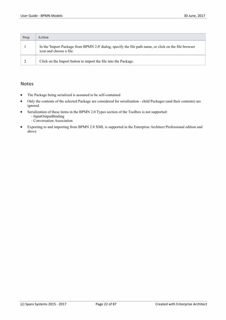
1 In the 'Import Package from BPMN 2.0' dialog, specify the file path name, or click on the file browsericon and choose a file.
2 Click on the Import button to import the file into the Package.
Notes
The Package being serialized is assumed to be self-contained·Only the contents of the selected Package are considered for serialization - child Packages (and their contents) are·ignored
Serialization of these items in the BPMN 2.0 Types section of the Toolbox is not supported:· - InputOutputBinding - Conversation Association
Exporting to and importing from BPMN 2.0 XML is supported in the Enterprise Architect Professional edition and·above
(c) Sparx Systems 2015 - 2017 Page 22 of 87 Created with Enterprise Architect

User Guide - BPMN Models 30 June, 2017
BPMN 1.0 and 1.1 Toolbox Pages
You can create graphical (Core) and non-graphical (Types) BPMN elements and relationships on business processdiagrams in BPMN 1.0, BPMN 1.1 and BPEL formats, using the BPMN 1.0 and BPMN 1.1 pages of the DiagramToolbox.
Access
Use any of the methods outlined here to display the Diagram Toolbox.
On the Diagram Toolbox, click on the More tools button and select either 'BPMN 1.0' or 'BPMN 1.1'.
Ribbon Design > Diagram > Toolbox : More Tools > BPMN 1.1
Keyboard Shortcuts Alt+5 : More Tools > BPMN 1.1
Other Click the icon on the Diagram caption bar to display the Diagram Toolbox, then
More Tools > BPMN 1.1
Toolbox
(c) Sparx Systems 2015 - 2017 Page 23 of 87 Created with Enterprise Architect

User Guide - BPMN Models 30 June, 2017
BPMN 1.1 Core Toolbox Page
Item Action
Business Process Extend a composite Activity that defines a business process.
BPEL Process Define the behavior of an executable or abstract business process.
Activity Represents work that is performed within a Business Process. An Activity can bemodeled as a:
Sub-Process - a compound Activity that is defined as a flow of other BPMN·1.1 elements or
Task - an atomic Activity that cannot be broken down into a smaller unit·
As a sub-process, the Activity can be made a composite element that links to a childdiagram containing the flow of other BPMN elements.
Start Event Define the initiating event in a process.
(c) Sparx Systems 2015 - 2017 Page 24 of 87 Created with Enterprise Architect

User Guide - BPMN Models 30 June, 2017
Intermediate Event Define an intermediate event in a process.
End Event Define the terminating event in a process.
Gateway Define a decision point in a business process.
If a condition is true, then processing continues one way; if not, then another.
Pool Extend a Partition element to logically organize an Activity.
Lane Extend a Partition element to subdivide a Pool.
Data Object Extend an Artifact element to define a physical piece of information used orproduced by a system.
Group Extend a Boundary element to group other elements.
Text Annotation Create a comment.
BPMN 1.1 Relationship Toolbox Page
Item Action
Sequence Flow Extend a Control Flow relationship to define the flow of activity.
Message Flow Extend a Control Flow relationship to define the flow of communications in theprocess.
Association Associate information and artifacts with flow objects.
BPMN 1.1 Types Toolbox Page
Item Action
Assignment Define the properties (Tagged Values) of the Core BPMN 1.1 elements such asActivities, Events and Gates.
Condition Define the properties (Tagged Values) of the Core BPMN 1.1 elements such asActivities, Events and Gates.
Message Define the properties (Tagged Values) of the Core BPMN 1.1 elements such asActivities, Events and Gates.
Participant Define the properties (Tagged Values) of the Core BPMN 1.1 elements such asActivities, Events and Gates.
(c) Sparx Systems 2015 - 2017 Page 25 of 87 Created with Enterprise Architect

User Guide - BPMN Models 30 June, 2017
Signal Define the properties (Tagged Values) of the Core BPMN 1.1 elements such asActivities, Events and Gates.
Rule Define the properties (Tagged Values) of the Core BPMN 1.1 elements such asActivities, Events and Gates.
Transaction Define the properties (Tagged Values) of the Core BPMN 1.1 elements such asActivities, Events and Gates.
Web Service Define the properties (Tagged Values) of the Core BPMN 1.1 elements such asActivities, Events and Gates.
Property Define the properties (Tagged Values) of the Core BPMN 1.1 elements such asActivities, Events and Gates.
(c) Sparx Systems 2015 - 2017 Page 26 of 87 Created with Enterprise Architect

User Guide - BPMN Models 30 June, 2017
Migrate BPMN 1.0 Model to BPMN 1.1
It is possible to migrate a BPMN 1.0 model (or part of a model) to BPMN 1.1 or BPMN1.1::BPEL, using the AutomationInterface. There are two functions you can use:
MigrateToBPMN11()· - proj.MigrateToBPMN11 sGUID, "BPMN" - proj.MigrateToBPMN11 sGUID, "BPEL"
Migrate()· - proj.Migrate sGUID, "BPMN", "BPMN1.1" - proj.Migrate sGUID, "BPMN", "BPMN1.1::BPEL"
These functions update the Tagged Values and, if required, stereotypes to BPMN 1.1 for all elements, attributes,connectors and diagrams under the selected Package or element.
Example
This VB script calls the MigrateToBPMN11() function to migrate the Tagged Values to BPMN 1.1:
Sub MigrateElement (sGUID, lngPackageID)
Dim proj as EA.Project
set proj = Repository.GetProjectInterface
proj.MigrateToBPMN11 sGUID, "BPMN"
'refresh the model
If lngPackageID<>0 Then
Repository.RefreshModelView (lngPackageID)
End If
End Sub
Sub MigrateSelectedItem
Dim selType
Dim selElement as EA.Element
Dim selPackage as EA.Package
selType = GetTreeSelectedItemType
If selType = 4 Then 'means Element
set selElement = GetTreeSelectedObject
MigrateElement selElement.ElementGUID, selElement.PackageID
MsgBox "Complete",0,"BPMN 1.1 Migration"
ElseIf selType = 5 Then 'means Package
set selPackage = GetTreeSelectedObject
MigrateElement selPackage.PackageGUID, selPackage.PackageID
MsgBox "Complete",0,"BPMN 1.1 Migration"
(c) Sparx Systems 2015 - 2017 Page 27 of 87 Created with Enterprise Architect

User Guide - BPMN Models 30 June, 2017
Else
MsgBox "Select a Package or Element in the Project Browser to initiate migration",0,"BPMN 1.1 Migration"
End If
End Sub
Sub Main
MigrateSelectedItem
End Sub
Main
Notes
In BPMN 1.0, various tags have free-text direct-entry value fields, and you can provide additional information on·these tags in the 'Tagged Value Note' dialog, for display at the bottom of the Tagged Values window
In BPMN 1.1, some of these tags (such as the Categories tag on a BusinessProcess stereotyped element) have beenchanged to Memo type, and you use the 'Tagged Value Note' dialog to enter the value; therefore, you cannot haveadditional notes for these tags, all information must be within the tag's value
For such tags, when migrating from BPMN 1.0 to BPMN 1.1, the BPMN 1.0 tag value is moved into the BPMN 1.1·tag 'Notes' field and the BPMN 1.0 tag notes are discarded; if you want to preserve the tag notes text, take a copy ofthe BPMN 1.0 model before migration to enable you to copy the tag notes text into the tag value after migration
(c) Sparx Systems 2015 - 2017 Page 28 of 87 Created with Enterprise Architect

User Guide - BPMN Models 30 June, 2017
Migrate BPMN 1.1 Model to BPMN 2.0
It is possible to migrate a BPMN 1.1 model (or part of a model) to BPMN 2.0, using the Automation Interface functionMigrate(). This function updates the Tagged Values and, if required, stereotypes to BPMN 2.0 for all elements,attributes, connectors and diagrams under the selected Package or element.
Example
This VB script calls the Migrate() function to migrate the Package or element to BPMN 2.0:
Sub MigrateElement (sGUID, lngPackageID)
Dim proj as EA.Project
set proj = Repository.GetProjectInterface
proj.Migrate sGUID, "BPMN1.1", "BPMN2.0"
'refresh the model
If lngPackageID<>0 Then
Repository.RefreshModelView (lngPackageID)
End If
End Sub
Sub MigrateSelectedItem
Dim selType
Dim selElement as EA.Element
Dim selPackage as EA.Package
selType = GetTreeSelectedItemType
If selType = 4 Then 'means Element
set selElement = GetTreeSelectedObject
MigrateElement selElement.ElementGUID, selElement.PackageID
MsgBox "Element Migration Completed",0,"BPMN 2.0 Migration"
ElseIf selType = 5 Then 'means Package
set selPackage = GetTreeSelectedObject
MigrateElement selPackage.PackageGUID, selPackage.PackageID
MsgBox "Package Migration Completed",0,"BPMN 2.0 Migration"
Else
MsgBox "Select a Package or Element in the Project Browser to initiate migration",0,"BPMN 2.0 Migration"
End If
End Sub
Sub Main
MigrateSelectedItem
End Sub
Main
(c) Sparx Systems 2015 - 2017 Page 29 of 87 Created with Enterprise Architect

User Guide - BPMN Models 30 June, 2017
Notes
Please backup your project before you run the BPMN 2.0 Migrator·Normalization occurs on these tags:· - BPMN1.1::Activity::InMessageRef - BPMN1.1::Activity::OutMessageRef - BPMN1.1::Activity::IORules - BPMN1.1::Activity::InputSets - BPMN1.1::Activity::OutputSets - BPMN1.1::Activity::ComplexMI_FlowCondition - BPMN1.1::Activity::Performers - BPMN1.1::BusinessProcess::InputSets - BPMN1.1::BusinessProcess::OutputSets - BPMN1.1::BusinessProcess::Performers - BPMN1.1::EndEvent::ErrorCode - BPMN1.1::IntermediateEvent::ErrorCode
Taking BPMN1.1::Activity::InMessageRef as an example, these steps take place:
(1) Create a new element BPMN2.0::Operation (this is the bridging element)(2) Insert the reference tag 'BPMN2.0::Activity::operationRef'(3) Migrate BPMN1.1::Activity::InMessageRef to BPMN2.0::Operation::InMessageRef
Denormalization occurs on these tags:· - A BPMN1.1::Transaction referenced by a BPMN1.1::Activity::TransactionRef > BPMN1.1::Transaction::TransactionMethod > BPMN1.1::Transaction::TransactionProtocol - A BPMN1.1::WebService referenced by a BPMN1.1::Activity::WebServiceRef, BPMN1.1::StartEvent::WebServiceRef, BPMN1.1::IntermediateEvent::WebServiceRef, BPMN1.1::EndEvent::WebServiceRef > BPMN1.1::WebService::Operation > BPMN1.1::WebService::Interface > BPMN1.1::WebService::ParticipantRef - A BPMN1.1::Condition referenced by a BPMN1.1::StartEvent::ConditionRef, BPMN1.1::IntermediateEvent::ConditionRef > BPMN1.1::Condition::ConditionExpression
Taking BPMN1.1::Activity::TransactionRef as an example, these steps take place:
(1) Find element BPMN1.1::Transaction by BPMN1.1::Activity::TransactionRef(2) Migrate this referenced BPMN1.1::Transaction::TransactionMethod's value toBPMN2.0::Activity::transactionMethod(3) Migrate this referenced BPMN1.1::Transaction::TransactionProtocol's value toBPMN2.0::Activity::transactionProtocol
If a BPMN1.1 stereo tag is discarded in BPMN2.0, it is preserved if the tag has a value·
(c) Sparx Systems 2015 - 2017 Page 30 of 87 Created with Enterprise Architect

User Guide - BPMN Models 30 June, 2017
Change BPMN Element Appearance
A number of Tagged Values directly affect the appearance of the BPMN element or connector they apply to. Therefore,you can change the appearance of the object by changing the value of the tags.
You can also set the 'reference' Tagged Value for a BPMN element that refers to another BPMN element, simply bydragging the referred-to element from the Project Browser onto the referring element in a diagram. See the Set ReferenceTagged Value table in this topic.
Access
Select a BPMN 1.1 element, then display the 'Properties' dialog, using any of the methods outlined in the table.
Ribbon Design > Element > Manage > Properties
Context Menu Right-click on element | Properties
Keyboard Shortcuts Alt+Enter
Other Double-click on a BPMN element
Define the appearance of BPMN elements and connectors
Step Action
1 The system opens the element 'Properties' dialog at the 'General' tab and displays the child tab 'BPMN1.1'.The 'BPMN1.1' tab lists the BPMN specific Tagged Values for the stereotype.
Where the element is a BPMN subtype, the 'Type' field shows the parent type. Click on the drop-downarrow to show the subtypes and, if necessary, select a different subtype. The list updates to show theTagged Values for the new subtype.
2 For each 'appearance' Tagged Value, the default value is shown (where relevant). If you want to add orchange values, click on the 'Value' field and either:
Type in the appropriate value (for a <memo> type, click on the button and type the text in the·'Tagged Value Note' dialog)
Click on the button and locate the defining object, or·Click on the drop-down arrow and select the appropriate value·
Suggested values are described in the Values for Tags table.
Tags for Activity Elements
Tag Value Description
(c) Sparx Systems 2015 - 2017 Page 31 of 87 Created with Enterprise Architect

User Guide - BPMN Models 30 June, 2017
activityType Set to:
Task for no decoration·Sub-Process to display the �plus-in-box decoration on the bottom edge of the·shape
adHoc Set to true to display the tilde decoration on the bottom edge of the shape,indicating that this is an ad-hoc Activity.
isACallActivity Set to true to show the boundary of the Activity element as a thick line, indicatingthat this is a Call Activity.
isATransaction Set to true to give the Activity element a double-lined border, indicating that this isa Transaction.
isForCompensation Set to true to display the rewind icon on the bottom edge of the shape, indicatingthat this is a Compensation Activity.
isSequential Set to true to display three horizontal bars on the bottom edge of the shape.
The loopCharacteristics tag must first be set to MultiInstance.
loopCharacteristics Set to:
Standard to display three vertical bars at the bottom edge of the shape·MultiInstance to display a loop icon at the bottom edge of the shape·
taskType When set to different value, the associated decoration is displayed at the top-leftcorner of the shape.
triggeredByEvent Set to true to show the boundary of the Activity element as a dotted line.
Tags for Choregraphy
Tag Value Description
choreographyType Set to:
Task for no decoration·Sub-Process to display the plus-in-box decoration on the bottom edge of the·shape.
isACallChoreography Set to true show the boundary of the Choreography element as a thick line.
loopType Set to:
Standard to display three vertical bars at the bottom edge of the shape·MultiInstance to display a loop icon at the bottom edge of the shape·
Each element has its own MultiInstance setting.
(c) Sparx Systems 2015 - 2017 Page 32 of 87 Created with Enterprise Architect

User Guide - BPMN Models 30 June, 2017
Tags for Conversation
Tag Value Description
isACallConversation Set to true to show the boundary of the Conversation element as a thick line.
isComposite Set to true to display a plus-in-box decoration on the bottom edge of the shape,indicating that the Conversation is a composite element.
Tags for Data Object
Tag Value Description
dataInOut Set to:
Input to add a light-colored arrow at the top-left corner of the Data Object,·indicating that it represents a Data Input element
Output to add a dark-colored arrow at the top-left corner of the Data Object,·indicating that it represents a Data Output element
isCollection Set to true to add three vertical lines at the bottom edge of the shape, indicating thatthe object is a collection.
Tags for Event
Tag Value Description
cancelActivity For Intermediate Event only.
Set to false to show the Intermediate Event border as a dashed line.
catchOrThrow For Intermediate Event only.
Set to:
Catch or·Throw·
eventDefinition Use to change the decoration of a Start Event, Intermediate Event or End Event.
isInterrupting For Start Event only.
Set to false to show the border of the Start Event as a dashed line, indicating thatthe Start Event is not an interrupting event.
Tags for Gateway
(c) Sparx Systems 2015 - 2017 Page 33 of 87 Created with Enterprise Architect

User Guide - BPMN Models 30 June, 2017
Tag Value Description
eventGatewayType Use to define two types of Event-based Gateway:
Exclusive and·Parallel·
gatewayType Set to:
Exclusive to render the Gateway as a diamond shape without any marker in the·middle; if you also set the markerVisible tag to True, the Gateway is renderedas a diamond shape with an X inside
Complex to render the Gateway as a diamond shape with an asterisk (*) inside·Inclusive to render the Gateway as a diamond shape with a circle (o) inside·Parallel to render the Gateway as a diamond shape with a plus (+) inside·Event to define the Gateway as Event-based·
instantiate Use only to define the Exclusive and Parallel Event-based Gateway.
Tags for Message
Tag Value Description
IsInitiate Set to true to make the envelope color gray, indicating that this is an initiatingMessage.
Tags for Message Flow
Tag Value Description
messageVisible Set to:
Unspecified to make the Message Flow connector without decoration·Initiating to add a white envelope to the Message Flow connector·Non-Initiating to add a gray envelope to the Message Flow connector·
Tags for Pool
Tag Value Description
blackBoxPool Set to true to render the Pool element as a rectangle, which is used in a Main Pooldiagram.
(c) Sparx Systems 2015 - 2017 Page 34 of 87 Created with Enterprise Architect
User Guide - BPMN Models 30 June, 2017
Tags for Sequence Flow
Tag Value Description
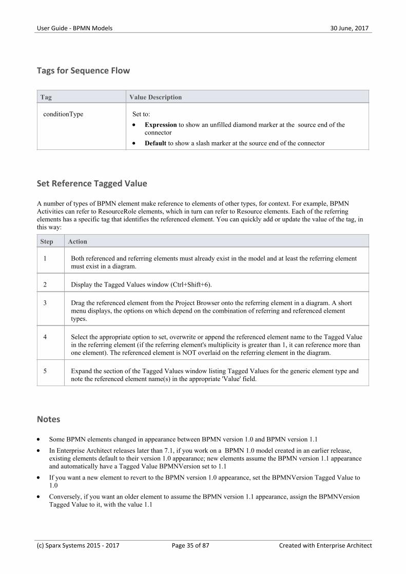
conditionType Set to:
Expression to show an unfilled diamond marker at the source end of the·connector
Default to show a slash marker at the source end of the connector·
Set Reference Tagged Value
A number of types of BPMN element make reference to elements of other types, for context. For example, BPMNActivities can refer to ResourceRole elements, which in turn can refer to Resource elements. Each of the referringelements has a specific tag that identifies the referenced element. You can quickly add or update the value of the tag, inthis way:
Step Action
1 Both referenced and referring elements must already exist in the model and at least the referring elementmust exist in a diagram.
2 Display the Tagged Values window (Ctrl+Shift+6).
3 Drag the referenced element from the Project Browser onto the referring element in a diagram. A shortmenu displays, the options on which depend on the combination of referring and referenced elementtypes.
4 Select the appropriate option to set, overwrite or append the referenced element name to the Tagged Valuein the referring element (if the referring element's multiplicity is greater than 1, it can reference more thanone element). The referenced element is NOT overlaid on the referring element in the diagram.
5 Expand the section of the Tagged Values window listing Tagged Values for the generic element type andnote the referenced element name(s) in the appropriate 'Value' field.
Notes
Some BPMN elements changed in appearance between BPMN version 1.0 and BPMN version 1.1·In Enterprise Architect releases later than 7.1, if you work on a BPMN 1.0 model created in an earlier release,·existing elements default to their version 1.0 appearance; new elements assume the BPMN version 1.1 appearanceand automatically have a Tagged Value BPMNVersion set to 1.1
If you want a new element to revert to the BPMN version 1.0 appearance, set the BPMNVersion Tagged Value to·1.0
Conversely, if you want an older element to assume the BPMN version 1.1 appearance, assign the BPMNVersion·Tagged Value to it, with the value 1.1
(c) Sparx Systems 2015 - 2017 Page 35 of 87 Created with Enterprise Architect

User Guide - BPMN Models 30 June, 2017
(c) Sparx Systems 2015 - 2017 Page 36 of 87 Created with Enterprise Architect

User Guide - BPMN Models 30 June, 2017
BPEL Models
This text is derived from the BPEL entry in the online Wikipedia:
'Business Process Execution Language (BPEL), short for Web Services Business Process Execution Language(WS-BPEL), is an executable language for specifying interactions with Web Services. Processes in Business ProcessExecution Language export and import information by using Web Service interfaces exclusively.'
Web service interactions can be described in two ways:
Executable business processes, which model the actual behavior of a participant in a business interaction.1.
Abstract business processes, which are partially specified processes that are not intended to be executed. An2.Abstract Process might hide some of the required concrete operational details.
BPEL is an Orchestration language, serialized in XML, which specifies an executable process that involves messageexchanges with other systems. This messaging facility depends on the use of the Web Services Description Language(WSDL) 1.1 to describe outgoing and incoming messages.
BPEL in Enterprise Architect:
Enterprise Architect supports generating BPEL from executable processes in the Business and Software Engineering andthe Ultimate editions. Although there is no standard graphical notation for WS-BPEL, Enterprise Architect uses BPMNprofile as a graphical front-end to capture BPEL Process descriptions. With the help of the BPMN Profile, EnterpriseArchitect enables you to develop BPEL diagrams quickly and simply. While BPMN provides a graphical notation forvisualizing business process, BPEL provides a way for visualizing this graphical business process in XML.
Enterprise Architect supports generating:
BPEL 1.1 Model from models created using constructs in BPMN 1.1 Profile·BPEL 2.0 Model from models created using constructs in BPMN 2.0 Profile·
Notes
BPEL is supported in the Business and Software Engineering and the Ultimate editions of Enterprise Architect·Enable BPMN 1.1 Technology for BPEL 1.1 modeling, and BPMN 2.0 Technology for BPEL 2.0 modeling, in the·'MDG Technologies' dialog ('Configure > Technology > Manage')
(c) Sparx Systems 2015 - 2017 Page 37 of 87 Created with Enterprise Architect

User Guide - BPMN Models 30 June, 2017
BPEL 1.1 Model
Enterprise Architect uses BPMN 1.1 as a graphical front-end to capture BPEL 1.1 Process description (as BPEL 1.1 doesnot have a standard graphical notation). Enterprise Architect uses the partial mapping specified in the OMG BPMN 1.1Specification to map BPMN 1.1 constructs to BPEL 1.1.
Create a BPEL 1.1 Model
Step Action
1 Create a BPEL 1.1 Package Structure.
Alternatively:
Create a Package in the Project Browser·Click on the 'New Diagram' icon in the Project Browser·Select 'BPMN 1.1' in the 'Select From' field and 'BPEL' in the 'Diagram Types' field·Click on the 'BPEL Process' icon from the BPMN 1.1 Core toolbox and drag it into the created BPEL·diagram
2 Open the BPEL diagram under the <<BPELProcess>> stereotyped element.
3 Model the BPEL Process using the constructs in the BPMN 1.1 Core page of the Diagram Toolbox; usethese constructs in each Toolbox page to model BPEL 1.1:
BPMN 1.1 - Core page:
BPEL Process·Activity·Start Event·Intermediate Event·End Event·Gateway·Pool·
BPMN 1.1 - Relationships page:
Sequence Flow·Message Flow·Association·
BPMN 1.1 Types page:
Assignment·Condition·Message·Participant·Web Service·
4 Create Web Service for the BPEL Process and other related Pools, if required.
5 Generate BPEL 1.1 code from the BPEL Process.
(c) Sparx Systems 2015 - 2017 Page 38 of 87 Created with Enterprise Architect

User Guide - BPMN Models 30 June, 2017
Notes
Generating BPEL 1.1 from a BPMN 1.1 model is supported in the Business and Software Engineering and the·Ultimate editions of Enterprise Architect
Ensure that BPMN 1.1 Technology is enabled in the 'MDG Technologies' dialog ('Configure > Technology >·Manage')
BPEL 1.1 Example
The Enterprise Architect Example file (EAExample.EAP) has a sample BPMN 1.1 model from which BPEL 1.1 can·be generated
If you have installed Enterprise Architect at the default location, open this file: C:\Program Files\Sparx·Systems\EA\EAExample.EAP
The BPMN 1.1 model Package is in: Example Model > Analysis and Business Modeling > BPEL Example > BPEL·1.1 Model
Modeling Restrictions
Every BPEL Process and Sub-Process should start with a Start Event and end with an End Event·A Start Event or an End Event should not be attached to the boundary of a Sub-Process·Sequence Flow Looping is not supported - only Activity looping is supported; all Sequence Flows should flow·downstream and not upstream
Mapping of an Intermediate Event with multiple triggers to BPEL 1.1 is not supported·Mapping of Multi-Instance Parallel While loops to BPEL 1.1 is not supported·Mapping of Independent Sub-Process to BPEL 1.1 is not supported·Pools are treated as black box (that is, they do not expose any details) and hence they cannot contain any child·elements or have any incoming/outgoing Sequence Flow connectors
(c) Sparx Systems 2015 - 2017 Page 39 of 87 Created with Enterprise Architect
User Guide - BPMN Models 30 June, 2017
Create BPEL 1.1 Model Structure
A BPEL 1.1 model consists of a BPEL Process (containing a BPEL diagram and mappable BPMN 1.1 constructs) andother supporting elements (like BPMN 1.1 Assignment, BPMN 1.1 Web Service) required for generating BPEL 1.1 code.A sample BPEL 1.1 Package structure can be created in the Project Browser, using the 'Select Model(s) (Model Wizard)'dialog. You can use this Package structure as a template for developing your BPEL Process.
Access
Ribbon Design > Package > Model Wizard
Context Menu Project Browser | Right-click on Package | Add a Model using Wizard
Keyboard Shortcuts Ctrl+Shift+M
Other Project Browser caption bar menu : New Model from Pattern
Create a new BPEL 1.1 Package structure as a starting point for developing a BPELProcess
Step Action
1 Select the root node or a Package in the Project Browser.
2 Click on the 'New Model from Pattern' drop-down menu option in the Project Browser header.
3 Select the value BPMN 1.1 i n the Technology section.
4 Check the option 'BPEL 1.1 Model' in the 'Name' section.
5 Click on the OK button to create the sample BPEL 1.1 Package structure.
Example BPEL 1.1 Package Structure:
The BPEL Process LoanApproval_Process acts as container for the BPEL diagram and elements. TheSupportingElements Package contains supporting components like Assignments and Web Services.
(c) Sparx Systems 2015 - 2017 Page 40 of 87 Created with Enterprise Architect

User Guide - BPMN Models 30 June, 2017
(c) Sparx Systems 2015 - 2017 Page 41 of 87 Created with Enterprise Architect

User Guide - BPMN Models 30 June, 2017
Model a BPEL 1.1 Process
The BPEL Process in Enterprise Architect represents the top-level container for the BPMN 1.1 elements, from whichBPEL 1.1 can be generated. Conceptually it maps to the BPEL process element.
BPEL Properties:
Double-click on the BPEL Process in the BPEL diagram·Right-click on the BPEL Process | BPEL | BPEL Properties·
Reference
Field/Button Action
Name Specify the name for the BPEL Process.
Query Language Specify the value of the language used in the BPEL Process for the selection ofnodes in Assignments. Defaults to XPath 1.0.
OK Save the values entered in the dialog.
Cancel Discard the values entered in the dialog.
Help Display this Help topic.
General Open the 'UML Properties' dialog.
(c) Sparx Systems 2015 - 2017 Page 42 of 87 Created with Enterprise Architect

User Guide - BPMN Models 30 June, 2017
Start Event
A BPMN 1.1 Start Event indicates where a particular Process begins. Every Process in Enterprise Architect must beginwith a Start Event.
BPEL Properties:
Double-click on the Start Event in the BPEL diagram (or)·Right-click on the Start Event | BPEL | BPEL Properties·
Reference
Option Action
Name Specify the name for the Start Event.
Trigger Type Select a trigger for the Start Event, namely:
Conditional·Link·Message·Multiple·None·Signal·Timer·
Details Tab Depending on the selected Trigger Type, the 'Details' tab changes as shown:
Conditional Trigger Type
Condition - Select a BPMN 1.1 Condition from the list of Condition(s) created·in the Supporting Elements Package
Message Trigger Type
Web Service - Select a BPMN 1.1 Web Servicefrom the Package (in the·Supporting Elements Package) that represents one of the involved Participants
Message - Select a BPMN 1.1 Message from the list of Message(s) in the·selected Web Service
Multiple Trigger Type
Events - Select additional BPMN 1.1 Start Events from the list of events in this·
Process that might trigger the Process, by clicking the button
Timer Trigger Type
Time Cycle - Specify the value for the time duration·Time Date - Specify the value for the time date·
Assignments Select one or more Assignment elements created in the SupportingElementsPackage in this tab (Optional).
OK Save the values entered in the dialog.
(c) Sparx Systems 2015 - 2017 Page 43 of 87 Created with Enterprise Architect

User Guide - BPMN Models 30 June, 2017
Cancel Discard the values entered in the dialog.
Help Display this Help topic.
General Open the 'UML Properties' dialog.
Notes
Set either 'Time Cycle' or 'Time Date for Timer Trigger Type' but not both as they are mutually exclusive fields·Link, None and Signal Event types cannot be mapped to BPEL 1.1·
(c) Sparx Systems 2015 - 2017 Page 44 of 87 Created with Enterprise Architect

User Guide - BPMN Models 30 June, 2017
Intermediate Event
A BPMN 1.1 Intermediate Event indicates where an event occurs somewhere between the start and end of a Process.
BPEL Properties:
Double-click on the Intermediate Event in the BPEL diagram·Right-click on the Intermediate Event | BPEL | BPEL Properties·
Reference
Field/Button Action
Name Specify the name for the Intermediate Event.
Trigger Type Select the type for the Intermediate Event, namely:
Cancel·Compensation·Conditional·Error·Link·Message·Multiple·None·Signal·Timer·
Details Tab Depending on the selected Trigger Type, the 'Details' tab changes as shown:
Compensation Trigger Type
Activity - Select a BPMN 1.1 Task from the list of all Activities in the Process·Conditional Trigger Type
Condition - Select a BPMN 1.1 Condition from the list of Condition(s) created·in the SupportingElements Package
Error Trigger Type
Error Code - Specify the required error code·Link Trigger Type
Link Event - Select a Link Event element (to act as a target for this Link Event)·from the list under the current Process/Sub-Process
Message Trigger Type
Web Service - Select a BPMN 1.1 Web Service from the Package (in the·SupportingElements Package) that represents one of the involved Participants
Message - Select a BPMN 1.1 Message from the list of Message(s) in the·selected Web Service
Multiple Trigger Type
(c) Sparx Systems 2015 - 2017 Page 45 of 87 Created with Enterprise Architect

User Guide - BPMN Models 30 June, 2017
Events - Select additional BPMN 1.1 Intermediate Events from the list of·
events in this Process, by clicking the button
Timer Trigger Type
Time Cycle - Specify the value for the time duration·Time Date - Specify the value for the time date·
OK Save the values entered in the dialog.
Cancel Discard the values entered in the dialog.
Help Display this Help topic.
General Open the 'UML Properties' dialog.
Notes
Cancel, None and Signal Event types cannot be mapped to BPEL 1.1·Set either 'Time Cycle' or 'Time Date for Timer Trigger Type' but not both as they are mutually exclusive fields·For a Compensation Intermediate Event edge-mounted on an Activity, create a BPMN 1.1 Association from this·event to the Compensation Activity; ensure that the IsCompensation tag for the Activity is set to true
Link Intermediate Event can be used either as a GOTO or an off-page connector; therefore, this event can have·either incoming or outgoing Sequence Flows - but not both
(c) Sparx Systems 2015 - 2017 Page 46 of 87 Created with Enterprise Architect

User Guide - BPMN Models 30 June, 2017
Activity
A BPMN 1.1 Activity represents work that is performed within a Process. An Activity can be modeled as a:
Sub-Process - a compound Activity that is defined as a flow of other BPMN 1.1 elements or·Task - an atomic Activity that cannot be broken down into a smaller unit·
Activities - both Tasks and Sub-Processes - can also, optionally, act as Looping constructs. The OMG BPMN 1.1Specification defines two types of Looping construct:
Standard Loop (while or until)·Multi-Instance Loop (for each)·
BPEL Properties:
Double-click on the Activity in the BPEL diagram·Right-click on the Activity | BPEL | BPEL 1.1 Properties·
Reference
Field/Button Action
Name Specify the name for the Activity.
Type Specify whether the Activity is a:
Task, or·Sub-Process·
Task Type / SubProcessType
Depending on the value selected in the 'Type' field, the 'Task Type / SubProcessType' field has these values:
Task Type:
Manual·None·Receive·Reference·Script·Send·Service·User·
SubProcess Type:
Embedded·References·Reusable·
Details Tab Depending on the selected Task Type, the 'Details' tab changes as shown.
Receive Task Type:
Web Service - Select a BPMN 1.1 Web Service from the Package (in the·
(c) Sparx Systems 2015 - 2017 Page 47 of 87 Created with Enterprise Architect

User Guide - BPMN Models 30 June, 2017
SupportingElements Package) that represents one of the involved Participants
Message - Select a BPMN 1.1 Message from the list of Message(s) in the·selected Web Service
Instantiate - Select True if this is the first Activity after the Start Event,·otherwise select False
Reference Task Type
Activity - Select a BPMN 1.1 Task from the list of all Activities in the Process·Send Task Type
Web Service - Select a BPMN 1.1 Web Service from the Package (in the·SupportingElements Package) that represents one of the involved Participants
Message - Select a BPMN 1.1 Message from the list of Message(s) in the·selected Web Service
Service / User Task Type
Web Service - Select a BPMN 1.1 Web Service from the Package (in the·SupportingElements Package) that represents one of the involved Participants
Input Message - Select a BPMN 1.1 Message from the list of Message(s) in the·selected Web Service that represents the input element
Output Message - Select a BPMN 1.1 Message from the list of Message(s) in·the selected Web Service that represents the output element
Depending on the selected SubProcess Type, the 'Details' tab changes as shown:
References SubProcess Type
SubProcess - Select a BPMN 1.1 Sub-Process from the list of all Activities in·the Process
Assignments Select one or more Assignment elements created in the SupportingElementsPackage in this tab (Optional).
Loop Details Activities can be repeated sequentially, behaving like a loop. Specify the Activitylooping details in this tab (Optional).
Type - Select 'Standard' for creating a 'while or until' loop, or 'MultiInstance'·for creating a 'for each' loop
Condition - Enter a boolean condition for Standard loop or a numeric condition·for MultiInstance loop
Min Value - Specify the minimum value for the loop evaluation for a Standard·loop (Optional)
Max Value - Specify the maximum value for the loop evaluation for a Standard·loop (Optional)
Test Time - Select 'After' to define a 'while' Standard loop or 'Before' to define·an 'until' Standard loop
OK Save the values entered in the dialog.
Cancel Discard the values entered in the dialog.
Help Display this Help topic.
General Open the 'UML Properties' dialog.
(c) Sparx Systems 2015 - 2017 Page 48 of 87 Created with Enterprise Architect

User Guide - BPMN Models 30 June, 2017
Notes
Manual and Script types cannot be mapped to BPEL 1.1·Reusable Sub - Process types cannot be mapped to BPEL 1.1·
(c) Sparx Systems 2015 - 2017 Page 49 of 87 Created with Enterprise Architect

User Guide - BPMN Models 30 June, 2017
Gateway
A BPMN 1.1 Gateway control the way in which Sequence Flows converge and diverge within a Process. They provide agating mechanism that either allows or blocks a Sequence Flow.
BPEL Properties:
Double-click on the Gateway in the BPEL diagram·Right-click on the Gateway | BPEL | BPEL Properties·
Reference
Field/Button Action
Name Specify the name for the Gateway.
Gateway Select the type for the Gateway, namely:
Complex·Exclusive·Inclusive·Parallel·
Details Tab Depending on the selected Gateway, the 'Details' tab changes as shown:
Exclusive Gateway
Exclusive Type:· - Data - allows alternate paths to be taken based on the evaluation ofconditions - Event - allows alternate paths to be taken based on the occurrence of events
OK Save the values entered in the dialog.
Cancel Discard the values entered in the dialog.
Help Display this Help topic.
General Open the 'UML Properties' dialog.
Notes
The target of the outgoing Sequence Flows of this Event Exclusive Gateway must be either a:·Receive Task or a·Message or Timer Intermediate Event·If a Message Task is one of the targets of the outgoing Sequence Flow of an Event Exclusive Gateway, then a·Message Intermediate Event cannot be the target of the other outgoing Sequence Flows of this Event Exclusive
(c) Sparx Systems 2015 - 2017 Page 50 of 87 Created with Enterprise Architect

User Guide - BPMN Models 30 June, 2017
Gateway
(c) Sparx Systems 2015 - 2017 Page 51 of 87 Created with Enterprise Architect

User Guide - BPMN Models 30 June, 2017
End Event
A BPMN 1.1 End Event indicates where a particular Process ends. Every Process in Enterprise Architect must end withan End Event.
BPEL Properties:
Double-click on the End Event in the BPEL diagram·Right-click on the End Event | BPEL | BPEL Properties·
Reference
Field/Button Action
Name Specify the name for the End Event.
Result Type Select the type for the End Event, namely:
Cancel·Compensation·Error·Link·Message·Multiple·None·Signal·Terminate·
Details Tab Depending on the selected Result Type, the 'Details' tab changes as shown:
Compensation Result Type
Activity - Select a BPMN 1.1 Task from the list of all Activities in the Process·Error Trigger Type
Error Code - Specify the required error code·Message Result Type
Web Service - Select a BPMN 1.1 Web Service from the Package (in the·SupportingElements Package) that represents one of the involved Participants
Message - Select a BPMN 1.1 Message from the list of Message(s) in the·selected Web Service
Multiple Result Type
Events - Select additional BPMN 1.1 Start Events from the list of events in this·
Process that might trigger the Process, by clicking on the button
Assignments Select one or more Assignment elements created in the SupportingElementsPackage in this tab (Optional).
OK Save the values entered in the dialog.
(c) Sparx Systems 2015 - 2017 Page 52 of 87 Created with Enterprise Architect

User Guide - BPMN Models 30 June, 2017
Cancel Discard the values entered in the dialog.
Help Display this Help topic.
General Open the 'UML Properties' dialog.
Notes
Cancel, Link, None and Signal Event types cannot be mapped to BPEL 1.1·
(c) Sparx Systems 2015 - 2017 Page 53 of 87 Created with Enterprise Architect

User Guide - BPMN Models 30 June, 2017
Sequence Flow
A BPMN 1.1 Sequence Flow connector shows the order in which the activities (Tasks and Events) are performed in aBPEL Process.
BPEL Properties:
Double-click on the Sequence Flow in the BPEL diagram·Right-click on the Sequence Flow | BPEL | BPELProperties·
Reference
Field/Button Action
Condition Type Specify the type of the condition on the Sequence Flow, namely:
None·Default·Expression·
Expression This field gets enabled when the Condition Type is set to Expression.
Specify a boolean expression to act as a gating condition.
Ordering This field gets enabled when the 'Condition Type' is set to 'Expression'.
Specify a numerical value that determines the order in which the condition set inthe 'Expression' field is to be evaluated.
Assignments Select one or more Assignment elements created in the SupportingElementsPackage in this tab (Optional).
OK Save the values entered in the dialog.
Cancel Discard the values entered in the dialog.
Help Display this Help topic.
General Open the 'UML Properties' dialog.
(c) Sparx Systems 2015 - 2017 Page 54 of 87 Created with Enterprise Architect
User Guide - BPMN Models 30 June, 2017
Pool
A BPMN 1.1 Pool represents a Participant in a Process and does not map to any specific BPEL 1.1 element. EnterpriseArchitect uses Pools to represent external Participants, with which the BPEL Process communicates. These are 'blackbox' pools; that is, they are abstract and do not expose any details (they do not contain any BPMN 1.1 elements insidethem).
BPEL Properties:
Double-click on the Pool in the BPEL diagram·Right-click on the Pool | BPEL | BPEL Properties·
Reference
Field/Button Action
Name Specify the name for the Pool.
OK Save the values entered in the dialog.
Cancel Discard the values entered in the dialog.
Help Display this Help topic.
General Open the 'UML Properties' dialog.
Notes
A BPEL Process should not contain a Pool as its child element·A BPEL diagram under a BPEL Process contains an implicit Pool - so it is invalid to add a Pool in this BPEL·diagram to represent the BPEL Process
Pool cannot have any incoming or outgoing Sequence Flow connectors - it can have only incoming or outgoing·Message Flow connectors
(c) Sparx Systems 2015 - 2017 Page 55 of 87 Created with Enterprise Architect

User Guide - BPMN Models 30 June, 2017
Assignment
A BPMN 1.1 Assignment element enables data to be copied between messages and new data to be inserted, usingexpressions within a BPEL Process. A BPMN 1.1 Assignment element maps to a BPEL 1.1 assign activity and copies thespecified value from the source to the target.
In Enterprise Architect, Assignment elements should be created in the Assignments Package in Create BPEL 2.0 Model Structure. If they are created elsewhere, they cannot be enacted correctly.
Access
Ribbon Design > Diagram > Toolbox : More tools > BPMN 1.1 > BPMN 1.1 Types
Keyboard Shortcuts Alt+5 : More tools | BPMN 1.1 | BPMN 1.1 Types
Other You can display or hide the Diagram Toolbox by clicking on the or icons atthe left-hand end of the Caption Bar at the top of the Diagram View.
BPEL Properties:
Double-click on the Assignment in the BPEL diagram·Right-click on the Assignment | BPEL | BPEL Properties·
Controls on BPEL Properties
Field/Button Action
Name Specify the name for the Assignment.
Assign Time Select either Start or End to determine whether the assignment occurs at the start orend of an Activity / Event.
Copy From Type Depending on the value selected in this field, further details are required.
Copy From Literal Specify a literal value.
Copy From Expression /Message
Select a BPMN 1.1 Message in the Package representing the BPEL Process / Poolunder the SupportingElements Package.
Copy From Part Select a BPMN 1.1 Property belonging to the selected Message (Optional).
Copy To Message Select a BPMN 1.1 Message in the Package representing the BPEL Process / Poolunder the SupportingElements Package.
Copy To Part Select a BPMN 1.1 Property belonging to the selected Message (Optional).
(c) Sparx Systems 2015 - 2017 Page 56 of 87 Created with Enterprise Architect

User Guide - BPMN Models 30 June, 2017
OK Save the values entered in the dialog.
Cancel Discard the values entered in the dialog.
Help Display this Help topic.
General Open the 'UML Properties' dialog.
Notes
Messages are created when you create Web Services·If you select Expression, Enterprise Architect uses the getVariableData XPATH 1.0 function to create the expression·from the selected Message and Part
(c) Sparx Systems 2015 - 2017 Page 57 of 87 Created with Enterprise Architect
User Guide - BPMN Models 30 June, 2017
Create BPEL 1.1 Web Service
BPEL is an Orchestration language, which orchestrates services that are exposed using WSDL 1.1. It coordinates theexecution of the various operations of these involved services. BPEL 1.1 supports WSDL 1.1 one-way andrequest-response operations only (and not solicit-response and notification operations). Enterprise Architect enables youto create, for BPEL Process and Pool elements, Web Service Operations that support either synchronous(request-response) or asynchronous (one-way) interactions.
Access
Context Menu In the Project Browser or on a diagram:
Right-click on a BPEL Process or Pool | BPEL | Create WebService
Options
Field/Button Action
Operation Specify whether to create a new Web Service or create one from an existing WSDLcreated / imported into Enterprise Architect (using the 'Import WSDL' dialog) byselecting either:
Create New (or)·Create from existing WSDL·
Type Specify whether to create a one-way or request-response Operation by selectingeither:
Asynchronous (or)·Synchronous·
Partnership Details The interaction between the Web Service and the BPEL Process is modeled as aBPEL partnerLink. For this interaction, provide a:
Name - Name of the BPEL partnerLink·Role - Name of either:· - myRole (if this operation belongs to the BPEL Process Web Service) or - partnerRole (if this operation belongs to the Web Service of a Pool)of the BPEL partnerLink
Web Service When 'Create New' is selected in the 'Operation' field:· - Web Service Name - Name of the WSDL 1.1 Web Service - PortType - Name of the WSDL 1.1 PortType (Interface) - Operation - Name of the WSDL 1.1 PortType Operation
When 'Create from existing WSDL PortType Operation' is selected in the·'Operation' field: - WSDL Package - Select an existing WSDL Package created / imported intoEnterprise Architect - Web Service Name - Name of the WSDL 1.1 Web Service; the default isthe name of the selected WSDL Package - PortType - Select a WSDL 1.1 PortType from the selected WSDL Package
(c) Sparx Systems 2015 - 2017 Page 58 of 87 Created with Enterprise Architect
User Guide - BPMN Models 30 June, 2017
- Operation - Select a WSDL 1.1 PortType Operation in the selectedPortType
Input When 'Create New' is selected in the 'Operation' field:
Message Name - Name of the WSDL 1.1 Message·
Properties - Click on the button to enter the WSDL 1.1 Message Part·Name and XSD Type
When 'Create from existing WSDL PortType Operation' is selected in the'Operation' field:
The fields in this tab are pre-filled with the details of the input WSDL 1.1·Message (of the WSDL 1.1 Port Type Operation selected in the 'Operation'field in the 'Web Service' tab)
Output When 'Create New' is selected in the 'Operation' field:
Message Name - The name of the WSDL 1.1 Message·
Properties - Click on the button to enter the WSDL 1.1 Message·Part Name and XSD Type
When 'Create from existing WSDL Port Type Operation' is selected in the'Operation' field:
The fields in this tab are pre-filled with the details of the output WSDL 1.1·Message (of the WSDL 1.1 Port Type Operation selected in the 'Operation'field in the 'Web Service' tab)
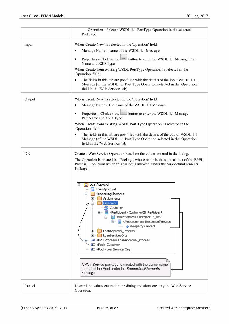
OK Create a Web Service Operation based on the values entered in the dialog.
The Operation is created in a Package, whose name is the same as that of the BPELProcess / Pool from which this dialog is invoked, under the SupportingElementsPackage.
Cancel Discard the values entered in the dialog and abort creating the Web ServiceOperation.
(c) Sparx Systems 2015 - 2017 Page 59 of 87 Created with Enterprise Architect

User Guide - BPMN Models 30 June, 2017
Help Display this Help topic.
Notes
The 'Output' tab is not applicable for an Asynchronous operation·
(c) Sparx Systems 2015 - 2017 Page 60 of 87 Created with Enterprise Architect

User Guide - BPMN Models 30 June, 2017
Generate BPEL 1.1
BPEL 1.1 code can be generated from a BPEL Process. Enterprise Architect validates the BPEL Process beforegenerating the BPEL 1.1 code. In addition to generating the BPEL 1.1 code, WSDL 1.1 files are generated for the BPELProcess and all of the involved Pools (provided that Web Services are defined for them).
Access
Context Menu In the Project Browser or on a diagram:
Right-click on a BPEL Process | BPEL | Generate BPEL
Reference
Field/Button Action
File Name Specify the path where the BPEL 1.1 file is to be generated.
Namespace Details Double-click on an entry (if any) in this field to open the 'Namespace Details'dialog and add / edit the namespace details.
The entry DefaultPool represents the current BPEL Process.
Generate BPEL Validate the model and generate BPEL 1.1.
Close Click on this button to close this dialog.
Help Display this Help topic.
View BPEL View the generated BPEL 1.1 file.
(c) Sparx Systems 2015 - 2017 Page 61 of 87 Created with Enterprise Architect

User Guide - BPMN Models 30 June, 2017
BPEL 2.0 Model
Enterprise Architect uses BPMN 2.0 as a graphical front-end to capture BPEL 2.0 Process description (as BPEL 2.0does not have a standard graphical notation). Enterprise Architect uses the partial mapping specified in the BPMN 2.0specification to map BPMN 2.0 constructs to BPEL 2.0.
Map Constructs
Step Action
1 Create a BPEL 2.0 Package Structure.
Alternatively:
Create a Package in the Project Browser.1.
Click on the 'New Diagram' option in the Project Browser header drop-down menu.2.
Select 'BPMN 2.0' in the 'Select From' field and 'BPEL' in the 'Diagram Types' field.3.
Click on the 'BPEL' icon from the BPMN 2.0 - Business Process Toolbox and drag it into the created4.BPEL diagram.
2 Open the BPEL diagram under the <<BPELProcess>> stereotyped element.
3 Model the BPEL Process using the constructs in the BPMN 2.0 - Business Process Toolbox. Use theseconstructs in this toolbox to model BPEL 2.0.
BPMN 2.0 - Business Process page:
BPEL·Activity·Data Object·Start Event·Intermediate Event·Event·Gateway·Pool·
BPMN 2.0 - Business Process Connectors page:
Sequence Flow·Association·Message Flow·
BPMN 2.0 Types page:
Assignment·Error·Interface·Operation·Property·
4 Create Web Service Operations for the BPEL Process and other related Pools, if required.
5 Generate BPEL 2.0 code from the BPEL Process.
(c) Sparx Systems 2015 - 2017 Page 62 of 87 Created with Enterprise Architect

User Guide - BPMN Models 30 June, 2017
Notes
Generating BPEL 2.0 from a BPMN 2.0 model is supported in the Business and Software Engineering and the·Ultimate editions of Enterprise Architect
Enable the BPMN 2.0 Technology in the 'MDG Technologies' dialog ('Configure > Technology > Manage')·
BPEL 2.0 Example
The Enterprise Architect Example file (EAExample.EAP) has a sample BPMN 2.0 model from which BPEL 2.0 can·be generated
If you have installed Enterprise Architect at the default location, open this file: C:\Program Files\Sparx·Systems\EA\EAExample.EAP
The BPMN 2.0 model Package is in: Example Model > Analysis and Business Modeling > BPEL Example > BPEL·2.0 Model
Modeling Restrictions
Every BPEL Process and Sub-Process should start with a Start Event and end with an End Event·Boundary Start and End Events are not supported·Sequence Flow Looping is not supported in both Normal and Exception Paths·All Sequence Flows should flow downstream and not upstream·Sub-Process cannot be a Loop node and have boundary Intermediate Events·Event Sub-Process cannot act as a Loop Node·Assignments are not supported on:· - Start Events on Event Sub-Processes - End Events - Sub-Processes - Boundary Intermediate Events - Gateways - Tasks and Intermediate Events that immediately follow an XOR Event Gateway
Exception Path has to merge back into the Normal Path·An exception to this rule is boundary Compensation Intermediate Event, which should have a BPMN 2.0·Association to a Compensation Activity (that has no incoming or outgoing Sequence Flows)
Multiple Exception Paths from an Activity must join at the same location in the Normal Path·An Exception Path should not cross another Exception Path·Activities in an Exception Path cannot have boundary Intermediate Events·Pools are treated as black boxes (that is, they do not expose any details) and hence they cannot contain any child·elements or have any incoming/outgoing Sequence Flow connectors
(c) Sparx Systems 2015 - 2017 Page 63 of 87 Created with Enterprise Architect

User Guide - BPMN Models 30 June, 2017
Create BPEL 2.0 Model Structure
A BPEL 2.0 model consists of a BPEL Process (containing a BPEL diagram and mappable BPMN 2.0 constructs) andother supporting elements (like BPMN 2.0 Assignment, BPMN 2.0 Operation) required for generating a BPEL 2.0 code.
A sample BPEL 2.0 Package structure can be created in the Project Browser, using the 'Select Model(s) (Model Wizard)'dialog. You can use this Package structure as a template for developing your BPEL Process.
Access
Ribbon Design > Package > Model Wizard
Context Menu Project Browser | Right-click on Package | Add a Model using Wizard
Keyboard Shortcuts Ctrl+Shift+M
Other Project Browser caption bar menu | New Model from Pattern
Create a BPEL 2.0 Package structure as a starting point for developing a BPELProcess
Step Action
1 Select the root node or a Package in the Project Browser.
2 Click on the 'New Model from Pattern' menu option in the Project Browser header.
3 Select the value BPMN 2.0 in the Technology section.
4 Check the option 'BPEL 2.0 Model' in the 'Name' section.
5 Click on the OK button to create the sample BPEL 2.0 Package structure.
Example BPEL 2.0 Package Structure
The BPEL Process LoanApproval_Process acts as container for the BPEL diagram and elements. TheSupportingElements Package contains supporting components like Assignments and Web Service Operations.
(c) Sparx Systems 2015 - 2017 Page 64 of 87 Created with Enterprise Architect

User Guide - BPMN Models 30 June, 2017
(c) Sparx Systems 2015 - 2017 Page 65 of 87 Created with Enterprise Architect

User Guide - BPMN Models 30 June, 2017
Model a BPEL 2.0 Process
The BPEL Process in Enterprise Architect represents the top-level container for the BPMN 2.0 elements, from whichBPEL 2.0 can be generated. Conceptually it maps to the BPEL process element.
BPEL Properties
Double-click on the BPEL Process in the BPEL diagram, or·Right-click on the BPEL Process in the BPEL diagram (or the Project Browser) and select BPEL | BPEL 2.0·Properties
Options
Field/Button Action
Name Specify the name for the BPEL Process.
Query Language Specify the language used in the BPEL Process for the selection of nodes inAssignments. Defaults to 'XPath 1.0'.
OK Save the values entered in the dialog.
Cancel Discard the values entered in the dialog.
Help Display this Help topic.
General Open the 'UML Properties' dialog.
(c) Sparx Systems 2015 - 2017 Page 66 of 87 Created with Enterprise Architect

User Guide - BPMN Models 30 June, 2017
Start Event
A BPMN 2.0 Start Event indicates where a particular Process begins. Every Process in Enterprise Architect must beginwith a Start Event.
BPEL Properties
Double-click on the Start Event in the BPEL diagram, or·Right-click on the Start Event | BPEL | BPEL 2.0 Properties·
Options
Field/Button Action
Name Type the name for the Start Event.
Event Type Select a trigger for the Start Event, namely:
Compensation·Conditional·Error·Escalation·Message·Multiple·None·Parallel Multiple·Signal·Timer·
Details Tab Depending on the selected Event Type, the 'Details' tab changes as shown:
Message Event Type· - Pool Package - Select the Package that represents one of the involvedParticipants - Operation - Select an Operation from the list of operation(s) in the selectedPool Package
Timer Event Type· - Time Cycle - Specify the value for the time duration - Time Date - Specify the value for the time date
Error Event Type· - Error - Select an Error element
Assignments (Optional) Select one or more Assignment elements created in theSupportingElements Package in this tab.
OK Save the values entered in the dialog.
Cancel Discard the values entered in the dialog.
(c) Sparx Systems 2015 - 2017 Page 67 of 87 Created with Enterprise Architect
User Guide - BPMN Models 30 June, 2017
Help Display this Help topic.
General Open the 'UML Properties' dialog.
Notes
Either set 'Time Cycle' or 'Time Date for Timer Event Type' but not both, as they are mutually exclusive fields·The 'Assignments' tab is not available on Start Events that are used to start an Event Sub-Process·Compensation, Error and Timer event types are valid only on an Event Sub-Process·Conditional, Escalation, Multiple, Parallel Multiple and Signal event types cannot be mapped to BPEL 2.0·
(c) Sparx Systems 2015 - 2017 Page 68 of 87 Created with Enterprise Architect
User Guide - BPMN Models 30 June, 2017
Intermediate Event
A BPMN 2.0 Intermediate Event indicates where an event occurs somewhere between the start and end of a Process.
BPEL Properties
Double-click on the Intermediate Event in the BPEL diagram·Right-click on the Intermediate Event | BPEL | BPEL 2.0 Properties·
Options
Field/Button Action
Name Specify the name for the Intermediate Event.
Event Type Select the type for the Intermediate Event, namely:
Cancel·Compensation·Conditional·Error·Escalation·Link·Message·Multiple·None·Parallel Multiple·Signal·Timer·
Details Tab Depending on the selected Event Type, the 'Details' tab changes:
Message Event Type· - Pool Package - Select the Package that represents one of the involvedParticipants - Operation - Select an Operation from the list of operation(s) in the selectedPool Package
Link Event Type· - Link Event - Select a Link Event element (to act as a target for this LinkEvent) from the list of Link Event elements under the current Process / Sub-Process
Timer Event Type· - Time Cycle - Specify the value for the time duration - Time Date - Specify the value for the time date
Compensation Event Type· - Activity - Select an Activity from the list of Activity elements under thecurrent Process / Sub-Process
Error Event Type·
(c) Sparx Systems 2015 - 2017 Page 69 of 87 Created with Enterprise Architect

User Guide - BPMN Models 30 June, 2017
- Error - Select an Error element
Assignments (Optional) Select one or more Assignment elements created in theSupportingElements Package in this tab.
OK Save the values entered in the dialog.
Cancel Discard the values entered in the dialog.
Help Display this Help topic.
General Open the 'UML Properties' dialog.
Notes
Cancel, Conditional, Escalation, Multiple, None, Parallel Multiple and Signal event type cannot be mapped to BPEL·2.0
The 'Assignments' tab is not available on Intermediate Events that are attached to the boundary of an Activity·Either set 'Time Cycle' or 'Time Date for Timer Trigger Type' but not both as they are mutually exclusive fields·The Error event type is valid only on an Intermediate Event attached to the boundary of an Activity·The Compensation event type is valid only on an Event Sub-Process or when attached to the boundary of an Activity·The Link Intermediate Event can be used either as a GOTO or an off-page connector; therefore, this event can have·either incoming or outgoing Sequence Flows - but not both
(c) Sparx Systems 2015 - 2017 Page 70 of 87 Created with Enterprise Architect

User Guide - BPMN Models 30 June, 2017
Activity
A BPMN 2.0 Activity represents work that is performed within a Process. An Activity can be modeled as a:
Sub-Process - a compound Activity that is defined as a flow of other BPMN 2.0 elements or·Task - an atomic Activity that cannot be broken down into a smaller unit·
Activities - both Tasks and Sub-Processes - can also, optionally, act as Looping constructs. The OMG BPMN 2.0Specification defines two types of Looping construct:
Standard Loop (while or until)·Multi-Instance Loop (for each)·
BPEL Properties
Double-click on the Activity in the BPEL diagram·Right-click on the Activity | BPEL | BPEL 2.0 Properties·
Options
Option Action
Name Type a name for the Activity.
Type Specify whether the Activity is a:
Task or·Sub-Process·
Task Type / SubProcessType
Depending on the value selected in the 'Type' field, the 'Task Type / SubProcessType' field has these values:
Task Type:· - Abstract - Business Rule - Manual - Receive - Script - Send - Service - User
SubProcess Type:· - Ad-Hoc - Call Activity - Compensation - Embedded - Event - Transaction
Details Tab Depending on the selected Task Type, the 'Details' tab changes:
Receive / Send / Service Task Type
Pool Package - Select the Package that represents one of the involved·Participants
(c) Sparx Systems 2015 - 2017 Page 71 of 87 Created with Enterprise Architect

User Guide - BPMN Models 30 June, 2017
Operation - Select an Operation from the list of operation(s) in the selected·Pool Package
Assignments (Optional) Select one or more Assignment elements created in theSupportingElements Package in this tab.
Loop Details (Optional) Activities can be repeated sequentially, behaving like a Loop. Specifythe Activity looping details in this tab.
Loop Type - Select 'Standard' for creating a 'while' or 'until' loop, or·'MultiInstance' for creating a 'for each' loop
Evaluate condition at the beginning of loop - Check this option to create a·'while' Standard loop; defaults to unselected for an 'until' loop
Loop Condition - Enter a boolean condition for a Standard loop or a numeric·condition for a MultiInstance loop
Loop Maximum - (Optional) Specify the maximum value for the loop·evaluation for a Standard loop
Loop Ordering - For a MultiInstanceLoop Type select 'Parallel' for generating·instances in parallel, or 'Sequential for generating instances in sequence
OK Click on this button to save the values entered in the dialog.
Cancel Click on this button to discard the values entered in the dialog.
Help Click on this button to display this Help topic.
General Click on this button to open the 'UML Properties' dialog.
Notes
The 'Assignments' tab is not applicable for Sub-Process·The 'Loop Details' tab is not applicable for Event Sub-Process·Business Rule, Manual, Script and User Task types cannot be mapped to BPEL 2.0·Ad-Hoc, Call Activity and Transaction Sub-Process types cannot be mapped to BPEL 2.0·
(c) Sparx Systems 2015 - 2017 Page 72 of 87 Created with Enterprise Architect
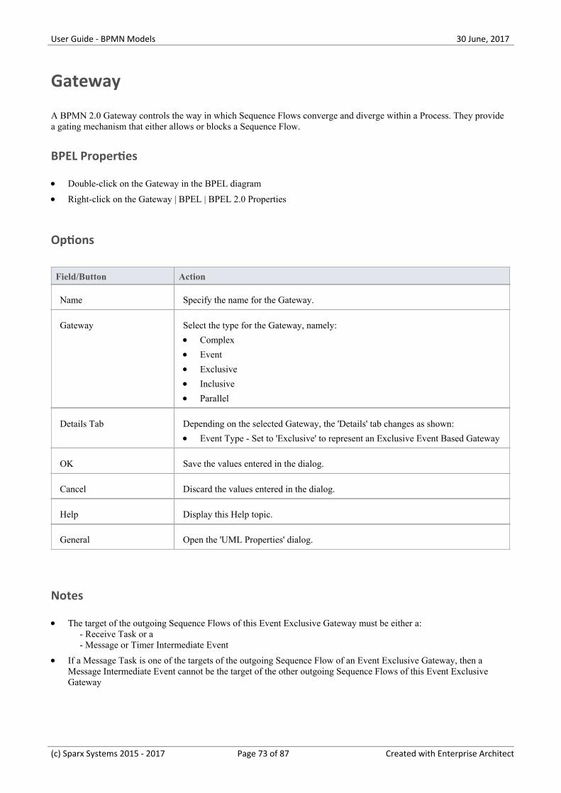
User Guide - BPMN Models 30 June, 2017
Gateway
A BPMN 2.0 Gateway controls the way in which Sequence Flows converge and diverge within a Process. They providea gating mechanism that either allows or blocks a Sequence Flow.
BPEL Properties
Double-click on the Gateway in the BPEL diagram·Right-click on the Gateway | BPEL | BPEL 2.0 Properties·
Options
Field/Button Action
Name Specify the name for the Gateway.
Gateway Select the type for the Gateway, namely:
Complex·Event·Exclusive·Inclusive·Parallel·
Details Tab Depending on the selected Gateway, the 'Details' tab changes as shown:
Event Type - Set to 'Exclusive' to represent an Exclusive Event Based Gateway·
OK Save the values entered in the dialog.
Cancel Discard the values entered in the dialog.
Help Display this Help topic.
General Open the 'UML Properties' dialog.
Notes
The target of the outgoing Sequence Flows of this Event Exclusive Gateway must be either a:· - Receive Task or a - Message or Timer Intermediate Event
If a Message Task is one of the targets of the outgoing Sequence Flow of an Event Exclusive Gateway, then a·Message Intermediate Event cannot be the target of the other outgoing Sequence Flows of this Event ExclusiveGateway
(c) Sparx Systems 2015 - 2017 Page 73 of 87 Created with Enterprise Architect

User Guide - BPMN Models 30 June, 2017
End Event
A BPMN 2.0 End Event indicates where a particular Process ends. Every Process in Enterprise Architect must end withan End Event.
BPEL Properties
Double-click on the End Event in the BPEL diagram·Right-click on the End Event | BPEL | BPEL 2.0 Properties·
Options
Field/Button Action
Name Specify the name for the End Event.
Event Type Select the type for the End Event, namely:
Cancel·Compensation·Error·Escalation·Message·Multiple·None·Signal·Terminate·
Details Tab Depending on the selected Event Type, the 'Details' tab changes:
Message Event Type:· - Pool Package - Select the Package that represents one of the involvedParticipants - Operation - Select an Operation from the list of operation(s) in the selectedPool Package
Compensation Event Type:· - Activity - Select an Activity from the list of Activity elements under thecurrent Process/Sub-Process
Error Event Type· - Error - Select an Error element
OK Save the values entered in the dialog.
Cancel Discard the values entered in the dialog.
Help Display this Help topic.
General Open the 'UML Properties' dialog.
(c) Sparx Systems 2015 - 2017 Page 74 of 87 Created with Enterprise Architect

User Guide - BPMN Models 30 June, 2017
Notes
The Compensation Event type is valid only on an Event Sub-Process·Cancel, Escalation, Multiple and Signal Event types cannot be mapped to BPEL 2.0·
(c) Sparx Systems 2015 - 2017 Page 75 of 87 Created with Enterprise Architect
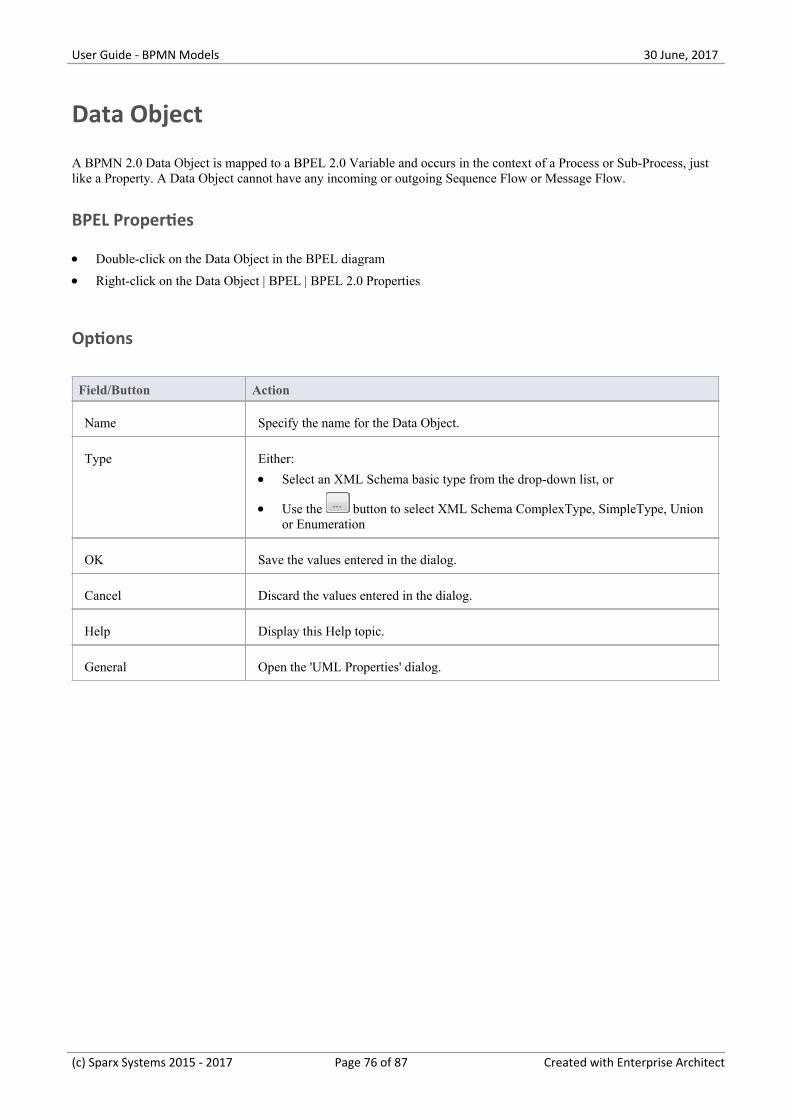
User Guide - BPMN Models 30 June, 2017
Data Object
A BPMN 2.0 Data Object is mapped to a BPEL 2.0 Variable and occurs in the context of a Process or Sub-Process, justlike a Property. A Data Object cannot have any incoming or outgoing Sequence Flow or Message Flow.
BPEL Properties
Double-click on the Data Object in the BPEL diagram·Right-click on the Data Object | BPEL | BPEL 2.0 Properties·
Options
Field/Button Action
Name Specify the name for the Data Object.
Type Either:
Select an XML Schema basic type from the drop-down list, or·
Use the button to select XML Schema ComplexType, SimpleType, Union·or Enumeration
OK Save the values entered in the dialog.
Cancel Discard the values entered in the dialog.
Help Display this Help topic.
General Open the 'UML Properties' dialog.
(c) Sparx Systems 2015 - 2017 Page 76 of 87 Created with Enterprise Architect

User Guide - BPMN Models 30 June, 2017
Property
A BPMN 2.0 Property is mapped to a BPEL 2.0 Variable and occurs in the context of a Process or Sub-Process, just likea Data Object.
However, unlike a Data Object, Property is not displayed on a BPEL diagram. Enterprise Architect supports Property onBPMN 2.0 BPEL and BPMN 2.0 Activity elements.
Access
Ribbon Design > Diagram > Toolbox : More tools > BPMN 2.0 > BPMN 2.0 BusinessProcess > BPMN 2.0 Types
Keyboard Shortcuts Alt+5 : More tools | BPMN 2.0 | BPMN 2.0 Business Process | BPMN 2.0 Types
Other You can display or hide the Diagram Toolbox by clicking on the or icons atthe left-hand end of the Caption Bar at the top of the Diagram View.
BPEL Properties
Right-click on the Property | BPEL | BPEL 2.0 Properties·
Options
Field/Button Action
Name Specify the name for the Property.
Type Either:
Select an XML Schema basic type from the drop-down list or·
Use the button to select XML Schema ComplexType, SimpleType, Union·or Enumeration
OK Save the values entered in the dialog.
Cancel Discard the values entered in the dialog.
Help Display this Help topic.
General Open the attribute properties.
(c) Sparx Systems 2015 - 2017 Page 77 of 87 Created with Enterprise Architect

User Guide - BPMN Models 30 June, 2017
Sequence Flow
A BPMN 2.0 Sequence Flow connector shows the order in which the activities (Tasks and Events) are performed in aBPEL Process.
Access BPEL Properties
Double-click on the Sequence Flow in the BPEL diagram·Right-click on the Sequence Flow | BPEL | BPEL 2.0 Properties·
Define the Sequence Flow
Field/Button Action
Condition Type Click on the drop-down arrow and select the type of the condition on the SequenceFlow, namely:
None·Default·Expression·
Expression This field is enabled when the 'Condition Type' is set to 'Expression'.
Type in a boolean expression to act as a gating condition.
Ordering This field is enabled when the 'Condition Type' is set to 'Expression'.
Type in a numerical value that determines the order in which the condition set inthe 'Expression' field is to be evaluated.
OK Click on this button to save the values entered in the dialog.
Cancel Click on this button to discard the values entered in the dialog.
Help Click on this button to display this Help topic.
General Click on this button to open the 'UML Properties' dialog.
(c) Sparx Systems 2015 - 2017 Page 78 of 87 Created with Enterprise Architect

User Guide - BPMN Models 30 June, 2017
Pool
A BPMN 2.0 Pool represents a Participant in a Process and does not map to any specific BPEL 2.0 element. EnterpriseArchitect uses Pools to represent external Participants, with which the BPEL Process communicates. These are 'blackbox' pools; that is, they are abstract and do not expose any details (they do not contain any BPMN 2.0 elements insidethem).
BPEL Properties
Double-click on the Pool in the BPEL diagram·Right -click on the Pool | BPEL | BPEL 2.0 Properties·
Options
Field/Button Action
Name Specify the name for the Pool.
OK Save the values entered in the dialog.
Cancel Discard the values entered in the dialog.
Help Display this Help topic.
General Open the 'UML Properties' dialog.
Notes
A BPEL Process should not contain a Pool as its child element·A BPEL diagram under a BPEL Process contains an implicit Pool, so it is invalid to add a Pool in this BPEL·diagram to represent the BPEL Process
Pool cannot have any incoming or outgoing Sequence Flow connectors - it can have only incoming or outgoing·Message Flow connectors
(c) Sparx Systems 2015 - 2017 Page 79 of 87 Created with Enterprise Architect

User Guide - BPMN Models 30 June, 2017
Assignment
A BPMN 2.0 Assignment element enables data to be copied between messages and variables within a BPEL Process. AnAssignment element maps to a BPEL 2.0 assign activity and copies the specified value from the source to the target.
In Enterprise Architect, Assignment elements should be created in the Assignments Package in SupportingElements. Ifthey are created elsewhere, they cannot be enacted correctly.
Access
Ribbon Design > Diagram > Toolbox : More tools > BPMN 2.0 > BPMN 2.0 BusinessProcess > BPMN 2.0 Types
Keyboard Shortcuts Alt+5 : More tools | BPMN 2.0 | BPMN 2.0 Business Process | BPMN 2.0 Types
Other You can display or hide the Diagram Toolbox by clicking on the or icons atthe left-hand end of the Caption Bar at the top of the Diagram View.
BPEL Properties
Double-click on the Assignment in the BPEL diagram·Right-click on the Assignment | BPEL | BPEL 2.0 Properties·
Options
Field/Button Action
Name Specify the name for the Assignment.
Copy From Complete the fields in this panel, as directed.
Type Depending on the value selected in this field, further details are required.
Literal Specify a literal value.
Expression Specify an expression.
Message Select a BPMN 2.0 Message in the Package representing the BPEL Process / Poolunder the SupportingElements Package.
Part Select a BPMN 2.0 Property belonging to the selected Message.
Variable Select a BPMN 2.0 Data Object or BPMN 2.0 Property created under the BPELProcess.
(c) Sparx Systems 2015 - 2017 Page 80 of 87 Created with Enterprise Architect

User Guide - BPMN Models 30 June, 2017
Copy To Complete the fields in this panel, as directed.
Message Select a BPMN 2.0 Message in the Package representing the BPEL Process / Poolunder the SupportingElements Package.
Part Select a BPMN 2.0 Property belonging to the selected Message.
Variable Select a BPMN 2.0 Data Object or BPMN 2.0 Property created under the BPELProcess.
OK Save the values entered in the dialog.
Cancel Discard the values entered in the dialog.
Help Display this Help topic.
General Open the 'UML Properties' dialog.
Notes
Messages are created when you create a Web Service Operation·
(c) Sparx Systems 2015 - 2017 Page 81 of 87 Created with Enterprise Architect
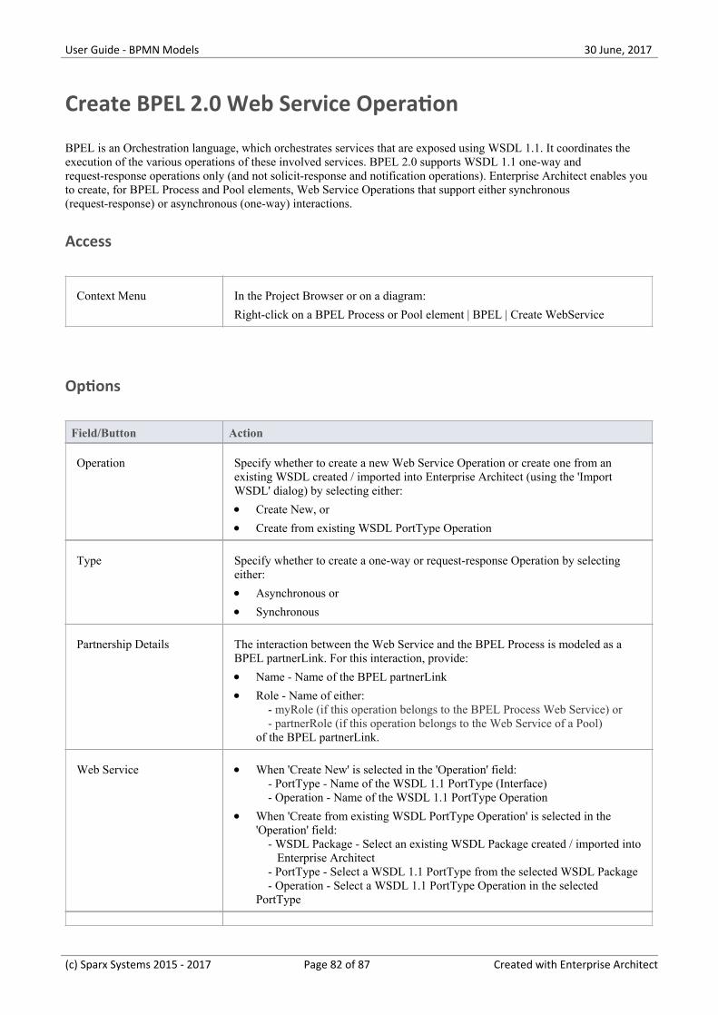
User Guide - BPMN Models 30 June, 2017
Create BPEL 2.0 Web Service Operation
BPEL is an Orchestration language, which orchestrates services that are exposed using WSDL 1.1. It coordinates theexecution of the various operations of these involved services. BPEL 2.0 supports WSDL 1.1 one-way andrequest-response operations only (and not solicit-response and notification operations). Enterprise Architect enables youto create, for BPEL Process and Pool elements, Web Service Operations that support either synchronous(request-response) or asynchronous (one-way) interactions.
Access
Context Menu In the Project Browser or on a diagram:
Right-click on a BPEL Process or Pool element | BPEL | Create WebService
Options
Field/Button Action
Operation Specify whether to create a new Web Service Operation or create one from anexisting WSDL created / imported into Enterprise Architect (using the 'ImportWSDL' dialog) by selecting either:
Create New, or·Create from existing WSDL PortType Operation·
Type Specify whether to create a one-way or request-response Operation by selectingeither:
Asynchronous or·Synchronous·
Partnership Details The interaction between the Web Service and the BPEL Process is modeled as aBPEL partnerLink. For this interaction, provide:
Name - Name of the BPEL partnerLink·Role - Name of either:· - myRole (if this operation belongs to the BPEL Process Web Service) or - partnerRole (if this operation belongs to the Web Service of a Pool)of the BPEL partnerLink.
Web Service When 'Create New' is selected in the 'Operation' field:· - PortType - Name of the WSDL 1.1 PortType (Interface) - Operation - Name of the WSDL 1.1 PortType Operation
When 'Create from existing WSDL PortType Operation' is selected in the·'Operation' field: - WSDL Package - Select an existing WSDL Package created / imported into Enterprise Architect - PortType - Select a WSDL 1.1 PortType from the selected WSDL Package - Operation - Select a WSDL 1.1 PortType Operation in the selectedPortType
(c) Sparx Systems 2015 - 2017 Page 82 of 87 Created with Enterprise Architect
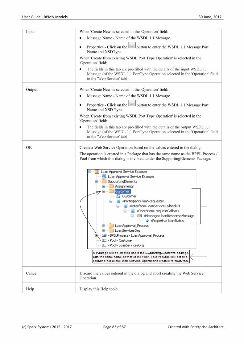
User Guide - BPMN Models 30 June, 2017
Input When 'Create New' is selected in the 'Operation' field:
Message Name - Name of the WSDL 1.1 Message.·
Properties - Click on the button to enter the WSDL 1.1 Message Part·Name and XSDType
When 'Create from existing WSDL Port Type Operation' is selected in the'Operation' field:
The fields in this tab are pre-filled with the details of the input WSDL 1.1·Message (of the WSDL 1.1 PortType Operation selected in the 'Operation' fieldin the 'Web Service' tab)
Output When 'Create New' is selected in the 'Operation' field:
Message Name - Name of the WSDL 1.1 Message·
Properties - Click on the button to enter the WSDL 1.1 Message Part·Name and XSD Type
When 'Create from existing WSDL Port Type Operation' is selected in the'Operation' field:
The fields in this tab are pre-filled with the details of the output WSDL 1.1·Message (of the WSDL 1.1 PortType Operation selected in the 'Operation' fieldin the 'Web Service' tab)
OK Create a Web Service Operation based on the values entered in the dialog.
The operation is created in a Package that has the same name as the BPEL Process /Pool from which this dialog is invoked, under the SupportingElements Package.
Cancel Discard the values entered in the dialog and abort creating the Web ServiceOperation.
Help Display this Help topic.
(c) Sparx Systems 2015 - 2017 Page 83 of 87 Created with Enterprise Architect

User Guide - BPMN Models 30 June, 2017
Notes
The 'Output' tab is not applicable for an Asynchronous operation·
(c) Sparx Systems 2015 - 2017 Page 84 of 87 Created with Enterprise Architect

User Guide - BPMN Models 30 June, 2017
Generate BPEL 2.0
BPEL 2.0 code can be generated from a BPEL Process. The system validates the BPEL Process before generating thecode. In addition to generating the code, WSDL 1.1 files are generated for the BPEL Process and all the involved Pools(provided Web Service Operations are defined for them).
Access
Context Menu In the Project Browser or on a diagram:
Right-click on a BPEL Process element | BPEL | Generate BPEL 2.0
Options
Field/Button Action
File Name Specify the path where the BPEL 2.0 file is to be generated.
Namespace Details Double-click on an entry (if any) in this field to open the 'Namespace Details'dialog and add / edit the namespace details.
The entry DefaultPool represents the current BPEL Process.
Generate BPEL Validate the model and generate BPEL 2.0.
Close Click on this button to close this dialog.
Help Display this Help topic.
View BPEL View the generated BPEL 2.0 file.
(c) Sparx Systems 2015 - 2017 Page 85 of 87 Created with Enterprise Architect

User Guide - BPMN Models 30 June, 2017
BPEL Model Validation
The BPEL model is validated for both syntax and semantic errors before generating the BPEL code. Upon successfulvalidation, the BPEL file (and the associated WSDL 1.1 files, if any) are generated. The results of the validation, as wellas the progress of the BPEL generation, are displayed in the 'BPEL Progress' tab of the System Output window.
Example BPEL Model Violation
This model shows several basic BPEL violations:
StartEvent1 is of type Signal, which cannot be mapped to BPEL·The Message Flow connector between StartEvent1 and Activity1 is invalid, as Message Flow cannot be used to·connect Activities or Events within a Process
EndEvent1 is of type Cancel, which cannot be mapped to BPEL·EndEvent1 cannot have any outgoing Sequence Flow connector, as it represents the end of a Process·Activity2 is not valid, as only an End Event represents the end of a Process·
Notes
Double-click on a validation error entry in the 'BPEL Progress' tab of the System Output window to go to the source·of the error in the Project Browser
(c) Sparx Systems 2015 - 2017 Page 86 of 87 Created with Enterprise Architect

User Guide - BPMN Models 30 June, 2017
(c) Sparx Systems 2015 - 2017 Page 87 of 87 Created with Enterprise Architect