Embed Size (px)
DESCRIPTION
Bpm n by Example Eng Bizagi This document gives you practical examples about how to use BPMN 2.0 notation to model business processes. Elements of each diagram will not be explained in detail but they will give you a general idea of how they can be used in real business processes.
Citation preview
BPMN by example
Bizagi Suite
Copyright © 2014 | Bizagi
Copyright © 2014 | Bizagi Confidential
Recruitment and Selection | 1
Table of Contents
Scope ........................................................................................................................................................ 2
BPMN 2.0 – Business Process Modeling Notation.................................................................. 2
Why Is It Important To Model With Bpmn? .......................................................................... 2
Introduction to BPMN ................................................................................................................... 3
Core Concepts ....................................................................................................................................... 4
Loan Request Process .................................................................................................................... 4
Travel Plan Quote Process ........................................................................................................... 6
Purchase Order Generation Process ........................................................................................ 7
Incident Management Process .................................................................................................. 9
Travel Request Process: Using The Transactional Sub-Process ...................................12
Collaboration diagrams ....................................................................................................................16
Sub-processes and call activities...................................................................................................18
Expanded Sub-Processes ............................................................................................................18
Collapsed Sub-Processes ............................................................................................................19
Using Call Activities....................................................................................................................... 20
BPMN elements summary ...............................................................................................................21
Flow Objects: ...............................................................................................................................21
Connection Objects: ................................................................................................................ 22
Swim Lanes: ................................................................................................................................ 23
Artifacts:........................................................................................................................................ 23
Copyright © 2014 | Bizagi Confidential
Recruitment and Selection | 2
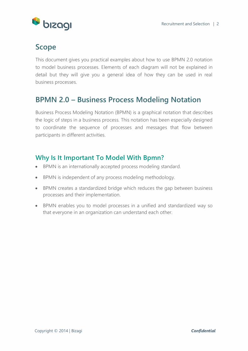
Scope
This document gives you practical examples about how to use BPMN 2.0 notation
to model business processes. Elements of each diagram will not be explained in
detail but they will give you a general idea of how they can be used in real
business processes.
BPMN 2.0 – Business Process Modeling Notation
Business Process Modeling Notation (BPMN) is a graphical notation that describes
the logic of steps in a business process. This notation has been especially designed
to coordinate the sequence of processes and messages that flow between
participants in different activities.
Why Is It Important To Model With Bpmn?
BPMN is an internationally accepted process modeling standard.
BPMN is independent of any process modeling methodology.
BPMN creates a standardized bridge which reduces the gap between business
processes and their implementation.
BPMN enables you to model processes in a unified and standardized way so
that everyone in an organization can understand each other.
Copyright © 2014 | Bizagi Confidential
Recruitment and Selection | 3
Introduction to BPMN
The Business Process Modeling Notation - BPMN – provides a common language
which allows all the parties involved to communicate processes clearly, completely
and efficiently. In this way, BPMN defines the notation and semantics of a Business
Process Diagram (BPD).
BPD is a diagram based on the ‘Flowchart’ technique, designed to present a
graphical sequence of all the activities that take place during a process. It also
includes all relative information for making an analysis.
BPD is a diagram designed for the use of process analysts who design, control and
manage processes. In a BPD diagram there are a series of graphical elements that
are grouped into categories.
Copyright © 2014 | Bizagi Confidential
Recruitment and Selection | 4
Core Concepts
This section introduces the basic concepts for modeling a process using BPMN. It
endeavours to show how it is possible to model many business situations using
BPMN. The diagrams will not be built step by step, but they should be references
to understand the use of the BPMN elements within a real business process
context.
Loan Request Process
The Loan Request Process handles the necessary activities to receive, analyze and
approve loan applications submitted by customers of a financial entity.
A simplified version of this process consists of a couple of activities. First, a
customer submits a loan request together with the required documents, then, the
information submitted is verified and the application is studied. Finally, the amount
of the loan is disbursed, if approved.
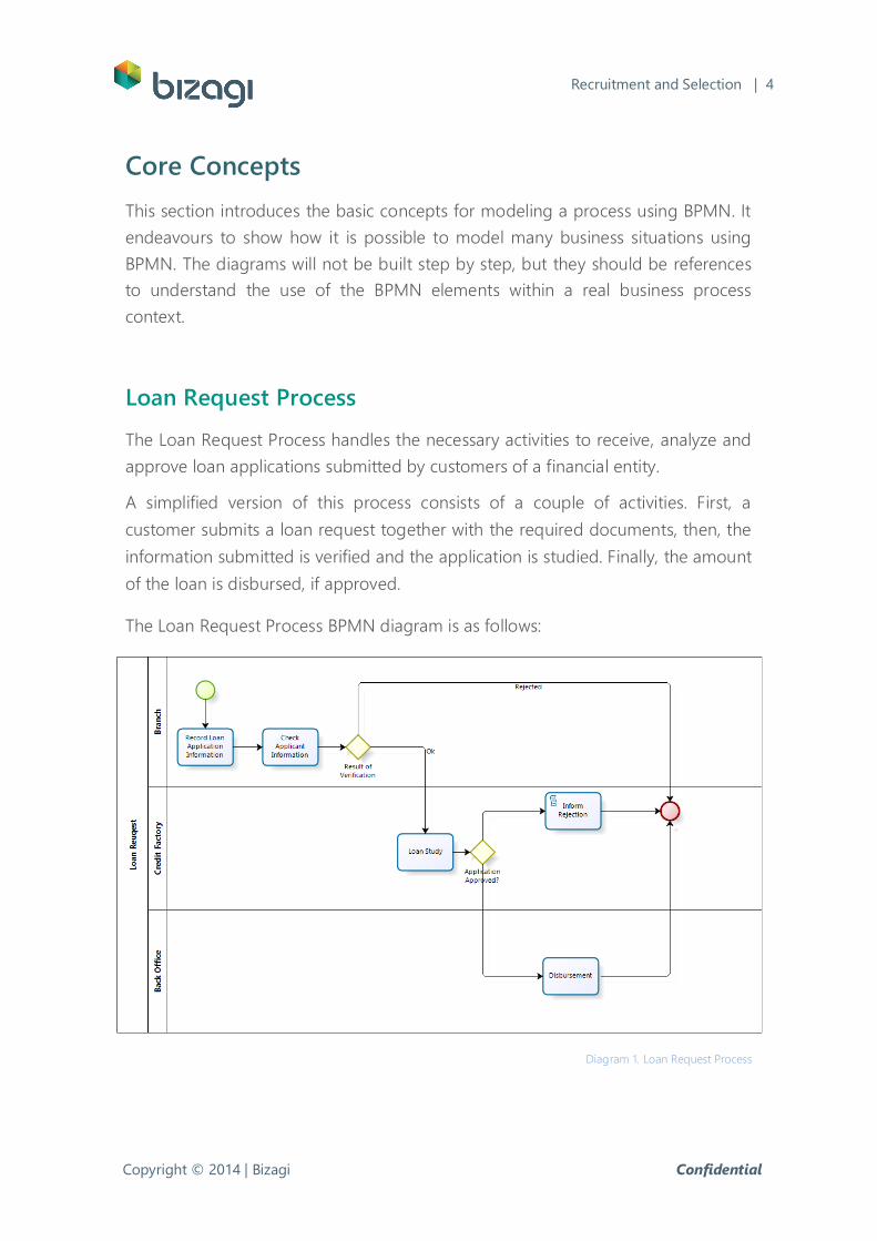
The Loan Request Process BPMN diagram is as follows:
Diagram 1. Loan Request Process
Copyright © 2014 | Bizagi Confidential
Recruitment and Selection | 5
As you can see, within a business process diagram, there is a set of graphical
elements that allow us to model it.
The business process diagrams are contained in objects known as pools that allow
us to represent the responsibilities in a process or simply identify the process.
BPMN also allows depicting the process performers through separators known as
Lanes. For this case the pool is called Loan Request and the lanes represent the
Branch, the credit factory and the back office as can be seen in the diagram.
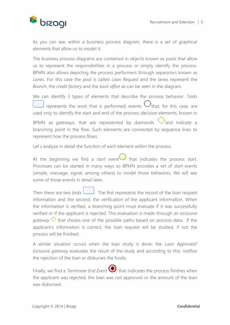
We can identify 3 types of elements that describe the process behavior: Tasks
represents the work that is performed; events that, for this case, are
used only to identify the start and end of the process; decision elements, known in
BPMN as gateways, that are represented by diamonds and indicate a
branching point in the flow. Such elements are connected by sequence lines to
represent how the process flows.
Let´s analyze in detail the function of each element within the process.
At the beginning we find a start event that indicates the process start.
Processes can be started in many ways so BPMN provides a set of start events
(simple, message, signal, among others) to model those behaviors. We will see
some of those events in detail later.
Then there are two tasks . The first represents the record of the loan request
information and the second, the verification of the applicant information. When
the information is verified, a branching point must evaluate if it was successfully
verified or if the applicant is rejected. This evaluation is made through an exclusive
gateway that choses one of the possible paths based on process data. If the
applicant’s information is correct, the loan request will be studied, if not the
process will be finished.
A similar situation occurs when the loan study is done: the Loan Approved?
Exclusive gateway evaluates the result of the study and according to this, notifies
the rejection of the loan or disburses the funds.
Finally, we find a Terminate End Event , that indicates the process finishes when
the applicant was rejected, the loan was not approved or the amount of the loan
was disbursed.
Copyright © 2014 | Bizagi Confidential
Recruitment and Selection | 6
Travel Plan Quote Process
This process handles request for quotes of travel plans made by customers of a
travel agency.
When a customer requests a quote, a travel agent must verify the availability and
calculate the costs of each of the services the customer included in the request
(Flight, hotel, car rental). When completed, a travel plan is built and the quote is
sent. If the customer is interested in the plan, a travel plan delivery process starts, if
not the process finishes.
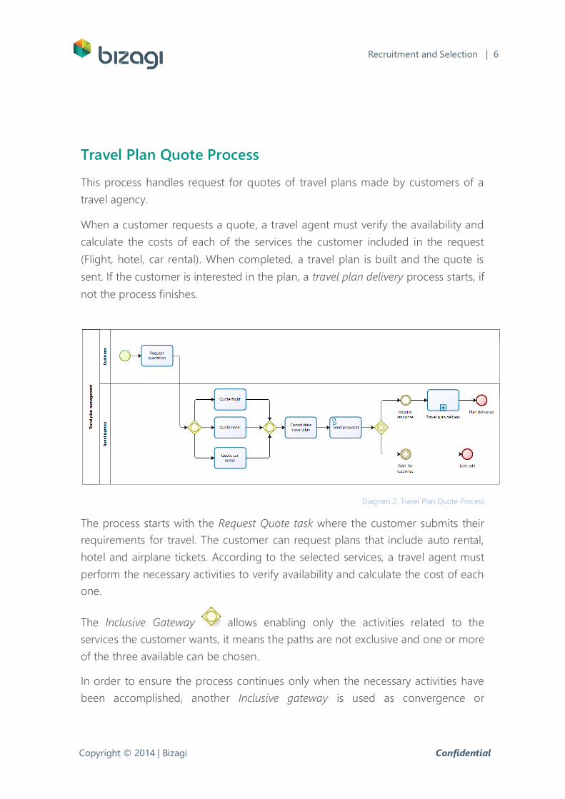
Diagram 2. Travel Plan Quote Process
The process starts with the Request Quote task where the customer submits their
requirements for travel. The customer can request plans that include auto rental,
hotel and airplane tickets. According to the selected services, a travel agent must
perform the necessary activities to verify availability and calculate the cost of each
one.
The Inclusive Gateway allows enabling only the activities related to the
services the customer wants, it means the paths are not exclusive and one or more
of the three available can be chosen.
In order to ensure the process continues only when the necessary activities have
been accomplished, another Inclusive gateway is used as convergence or
Copyright © 2014 | Bizagi Confidential
Recruitment and Selection | 7
synchronization, so the flow is allowed to continue when all the active paths are
joined.
Once the requested services have been managed, the travel agent consolidates
the travel plan based on their availability and costs, and then the proposal is sent
to the customer via email. The email sending is modeled using script tasks .
This kind of task allows the execution of scripts that the modeler defines.
The next shape we find in the flow is an Event-Based Gateway . This gateway
represents a decision point in the process where the selection of a path depends
on events rather than process data.
In this case two events can occur: the Receive Response None Intermediate event
,that is manually executed by the travel agent when he/she has received a
positive response from the customer, or the Wait Response Timer event , that
waits a specific time for the customer response. The event that is activated first
enables its related path and the other will be no longer valid. This means that if
the customer does not give a response to the quote after a specific time, the
process finishes when reaching the End Event .
In case the customer gives a positive response to the quotation, a travel plan
delivery process must start. This is depicted in the diagram by a sub-process
which is a set of activities with a logical sequence (a process) thus this can be
broken down into more levels of detail. This sub-process represents the activities
that the administrative department must perform in order to delivery and invoice
the services to the customer.
Finally the process finishes when it reaches the End Event .
Purchase Order Generation Process
The goal of this process is to automatically generate purchase orders according to
the raw materials inventory levels and to manage their approval, record them in
the company accounting system and deliver them to suppliers.
Copyright © 2014 | Bizagi Confidential
Recruitment and Selection | 8
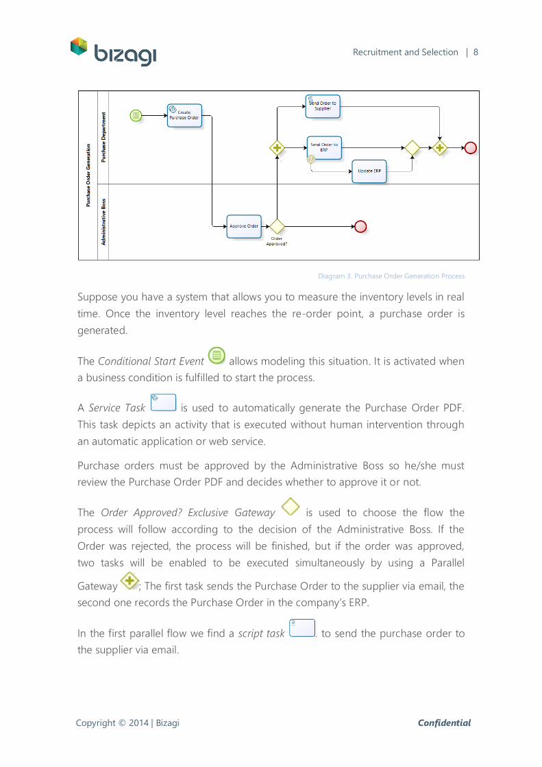
Diagram 3. Purchase Order Generation Process
Suppose you have a system that allows you to measure the inventory levels in real
time. Once the inventory level reaches the re-order point, a purchase order is
generated.
The Conditional Start Event allows modeling this situation. It is activated when
a business condition is fulfilled to start the process.
A Service Task is used to automatically generate the Purchase Order PDF.
This task depicts an activity that is executed without human intervention through
an automatic application or web service.
Purchase orders must be approved by the Administrative Boss so he/she must
review the Purchase Order PDF and decides whether to approve it or not.
The Order Approved? Exclusive Gateway is used to choose the flow the
process will follow according to the decision of the Administrative Boss. If the
Order was rejected, the process will be finished, but if the order was approved,
two tasks will be enabled to be executed simultaneously by using a Parallel
Gateway ; The first task sends the Purchase Order to the supplier via email, the
second one records the Purchase Order in the company’s ERP.
In the first parallel flow we find a script task . to send the purchase order to
the supplier via email.
Copyright © 2014 | Bizagi Confidential
Recruitment and Selection | 9
In the second one, we find a Service Task with an attached event . Such
event is a Catch Error Event . The service task allows recording the Purchase
Order into the company’s ERP through an interface, however, if during the
execution of this task an error arises (network connection error, etc.) the error
event is triggered and the next task is enabled. In this case the Update ERP task is
enabled in order to manually record the Purchase Order in the company’s ERP.
In order to synchronize the active flows we find two gateways. The exclusive
gateway synchronizes the flows related to the activities Send Order to the ERP
and Update ERP. In the same way, the parallel gateway merges the parallel
paths previously enabled. Once both paths reach this gateway, the process
finishes due to the End Event .
Incident Management Process
The goal of the incident management process is handling and solving failures and
disruptions in the technological infrastructure to avoid affecting the normal
performance of business activities within an organization.
The process starts when a user reports an incident. This incident is handled by
technicians that find a solution, communicate it to the user and record the
procedure followed to solve the incident in a knowledge base. Finally the case is
closed.
The following diagram shows a more complex situation of this process. This
include activities that must be carried out, in an exceptional way, when the
incident is too serious or it is not possible to solve it in a specific period of time.
Copyright © 2014 | Bizagi Confidential
Recruitment and Selection | 10
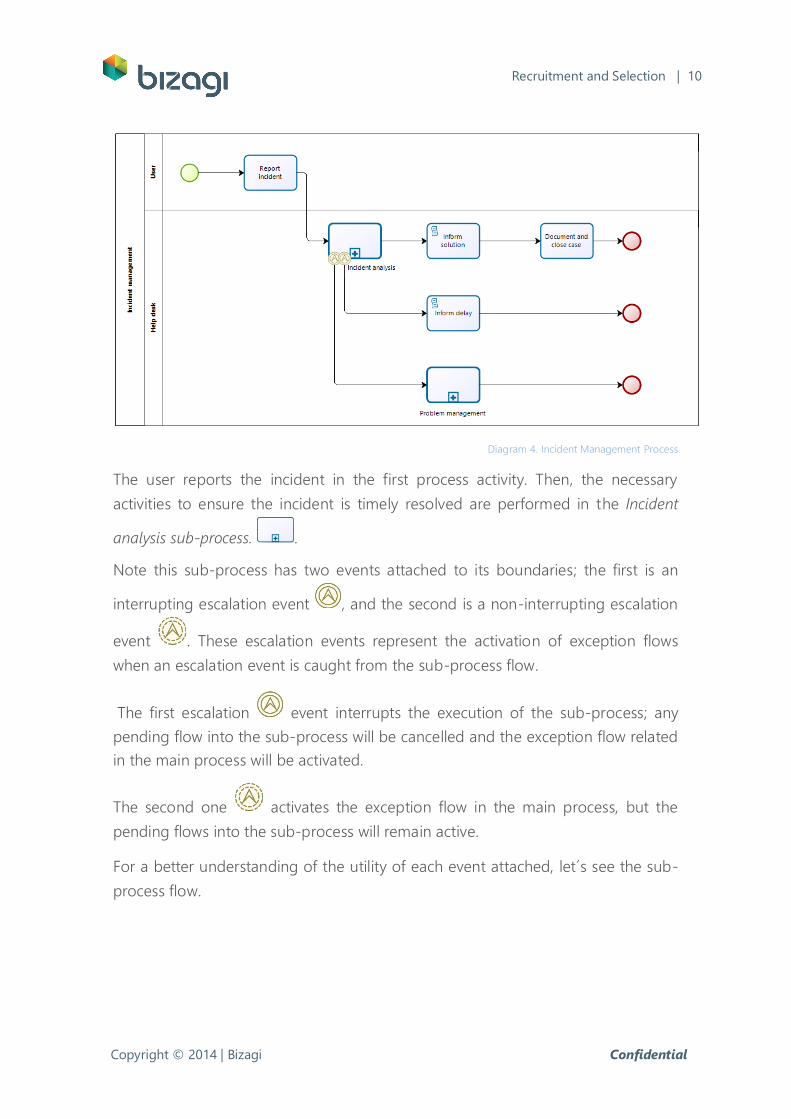
Diagram 4. Incident Management Process
The user reports the incident in the first process activity. Then, the necessary
activities to ensure the incident is timely resolved are performed in the Incident
analysis sub-process. .
Note this sub-process has two events attached to its boundaries; the first is an
interrupting escalation event , and the second is a non-interrupting escalation
event . These escalation events represent the activation of exception flows
when an escalation event is caught from the sub-process flow.
The first escalation event interrupts the execution of the sub-process; any
pending flow into the sub-process will be cancelled and the exception flow related
in the main process will be activated.
The second one activates the exception flow in the main process, but the
pending flows into the sub-process will remain active.
For a better understanding of the utility of each event attached, let´s see the sub-
process flow.
Copyright © 2014 | Bizagi Confidential
Recruitment and Selection | 11
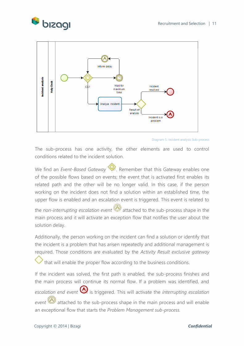
Diagram 5. Incident analysis Sub-process
The sub-process has one activity, the other elements are used to control
conditions related to the incident solution.
We find an Event-Based Gateway . Remember that this Gateway enables one
of the possible flows based on events; the event that is activated first enables its
related path and the other will be no longer valid. In this case, if the person
working on the incident does not find a solution within an established time, the
upper flow is enabled and an escalation event is triggered. This event is related to
the non-interrupting escalation event attached to the sub-process shape in the
main process and it will activate an exception flow that notifies the user about the
solution delay.
Additionally, the person working on the incident can find a solution or identify that
the incident is a problem that has arisen repeatedly and additional management is
required. Those conditions are evaluated by the Activity Result exclusive gateway
that will enable the proper flow according to the business conditions.
If the incident was solved, the first path is enabled, the sub-process finishes and
the main process will continue its normal flow. If a problem was identified, and
escalation end event is triggered. This will activate the interrupting escalation
event attached to the sub-process shape in the main process and will enable
an exceptional flow that starts the Problem Management sub-process.
Copyright © 2014 | Bizagi Confidential
Recruitment and Selection | 12
Travel Request Process: Using The Transactional Sub-
Process
Transactional processes are used to coordinate multiple activities that have to be
successfully completed. We will use the Travel Request process to show you how
this kind of process is used.
A Travel Request process includes the necessary activities to receive and handle
travel requests made by the employees of a company. This is a very simple
process if we do not take into account the unexpected situations that can arise.
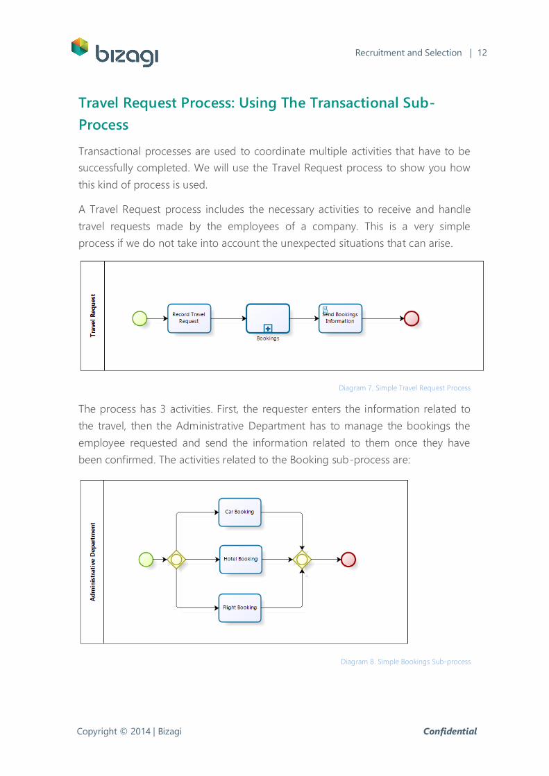
Diagram 7. Simple Travel Request Process
The process has 3 activities. First, the requester enters the information related to
the travel, then the Administrative Department has to manage the bookings the
employee requested and send the information related to them once they have
been confirmed. The activities related to the Booking sub-process are:
Diagram 8. Simple Bookings Sub-process
Copyright © 2014 | Bizagi Confidential
Recruitment and Selection | 13
The Administrative Department can manage the car, hotel and flight bookings
simultaneously as requested by the employee. When completed, the sub-process
finishes. However, many situations can arise during the process development.
Suppose the Administrative Department has successfully confirmed the car and
hotel booking. But when the flight is going to be booked, no airline has flight
availability on the requested date. The car and hotel were already booked for that
date so they have to be undone and the employee must be notified about this
situation. This can be modeled as follow:
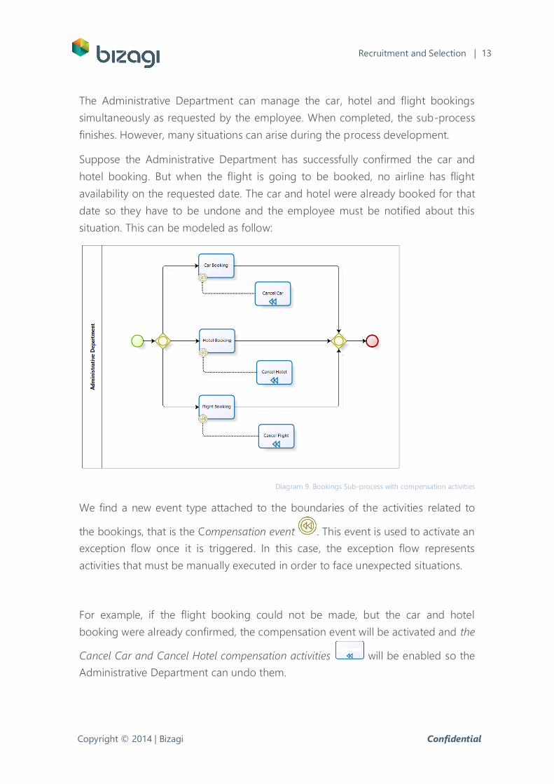
Diagram 9. Bookings Sub-process with compensation activities
We find a new event type attached to the boundaries of the activities related to
the bookings, that is the Compensation event . This event is used to activate an
exception flow once it is triggered. In this case, the exception flow represents
activities that must be manually executed in order to face unexpected situations.
For example, if the flight booking could not be made, but the car and hotel
booking were already confirmed, the compensation event will be activated and the
Cancel Car and Cancel Hotel compensation activities will be enabled so the
Administrative Department can undo them.
Copyright © 2014 | Bizagi Confidential
Recruitment and Selection | 14
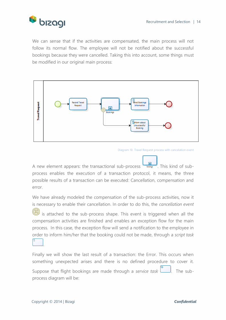
We can sense that if the activities are compensated, the main process will not
follow its normal flow. The employee will not be notified about the successful
bookings because they were cancelled. Taking this into account, some things must
be modified in our original main process:
Diagram 10. Travel Request process with cancelation event
A new element appears: the transactional sub-process . This kind of sub-
process enables the execution of a transaction protocol, it means, the three
possible results of a transaction can be executed: Cancellation, compensation and
error.
We have already modeled the compensation of the sub-process activities, now it
is necessary to enable their cancellation. In order to do this, the cancellation event
is attached to the sub-process shape. This event is triggered when all the
compensation activities are finished and enables an exception flow for the main
process. In this case, the exception flow will send a notification to the employee in
order to inform him/her that the booking could not be made, through a script task
.
Finally we will show the last result of a transaction: the Error. This occurs when
something unexpected arises and there is no defined procedure to cover it.
Suppose that flight bookings are made through a service task . The sub-
process diagram will be:
Copyright © 2014 | Bizagi Confidential
Recruitment and Selection | 15
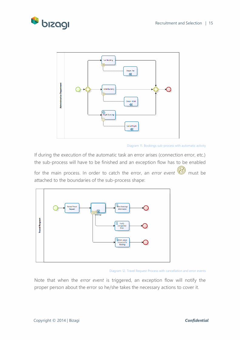
Diagram 11. Bookings sub-process with automatic activity
If during the execution of the automatic task an error arises (connection error, etc.)
the sub-process will have to be finished and an exception flow has to be enabled
for the main process. In order to catch the error, an error event must be
attached to the boundaries of the sub-process shape:
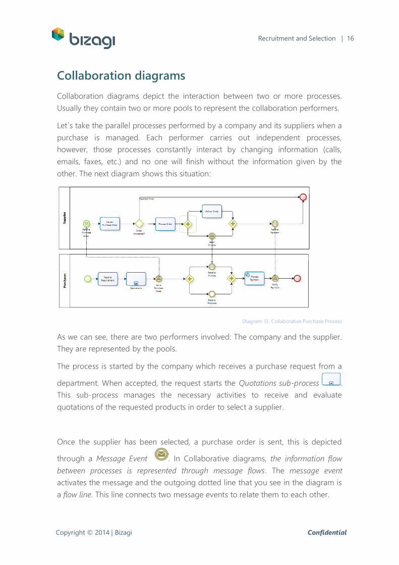
Diagram 12. Travel Request Process with cancellation and error events
Note that when the error event is triggered, an exception flow will notify the
proper person about the error so he/she takes the necessary actions to cover it.
Copyright © 2014 | Bizagi Confidential
Recruitment and Selection | 16
Collaboration diagrams
Collaboration diagrams depict the interaction between two or more processes.
Usually they contain two or more pools to represent the collaboration performers.
Let´s take the parallel processes performed by a company and its suppliers when a
purchase is managed. Each performer carries out independent processes,
however, those processes constantly interact by changing information (calls,
emails, faxes, etc.) and no one will finish without the information given by the
other. The next diagram shows this situation:
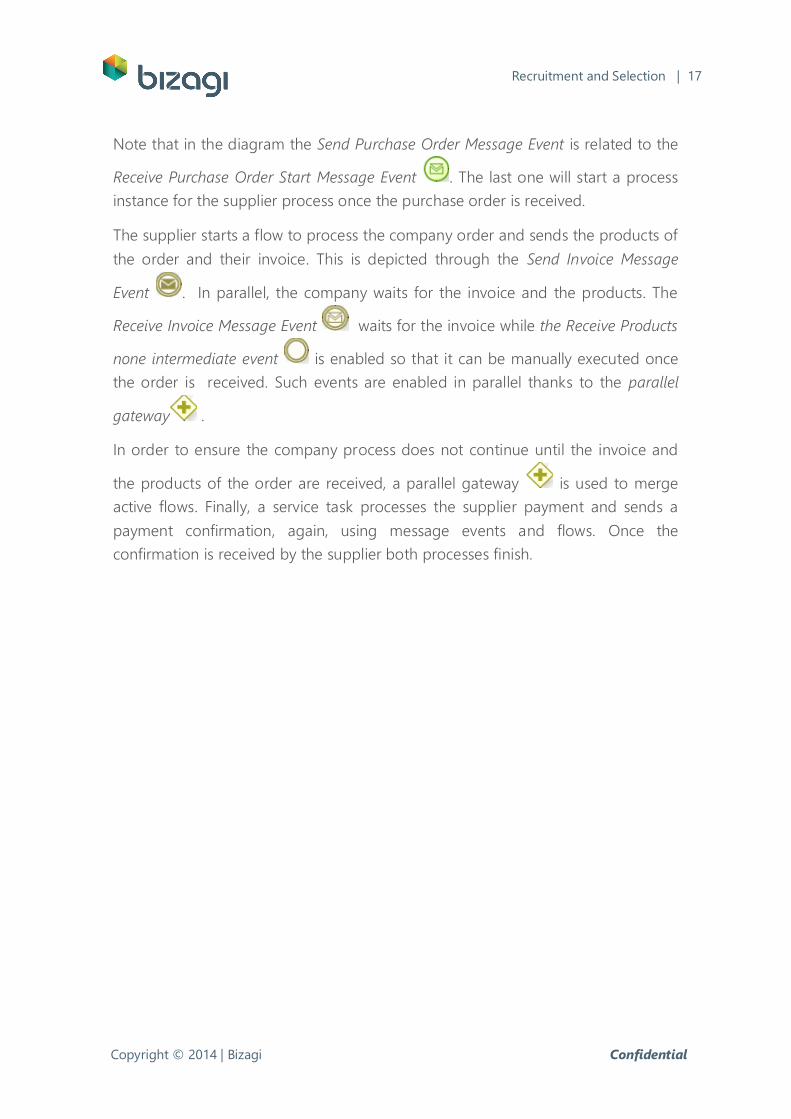
Diagram 13. Collaborative Purchase Process
As we can see, there are two performers involved: The company and the supplier.
They are represented by the pools.
The process is started by the company which receives a purchase request from a
department. When accepted, the request starts the Quotations sub-process .
This sub-process manages the necessary activities to receive and evaluate
quotations of the requested products in order to select a supplier.
Once the supplier has been selected, a purchase order is sent, this is depicted
through a Message Event . In Collaborative diagrams, the information flow
between processes is represented through message flows. The message event
activates the message and the outgoing dotted line that you see in the diagram is
a flow line. This line connects two message events to relate them to each other.
Copyright © 2014 | Bizagi Confidential
Recruitment and Selection | 17
Note that in the diagram the Send Purchase Order Message Event is related to the
Receive Purchase Order Start Message Event . The last one will start a process
instance for the supplier process once the purchase order is received.
The supplier starts a flow to process the company order and sends the products of
the order and their invoice. This is depicted through the Send Invoice Message
Event . In parallel, the company waits for the invoice and the products. The
Receive Invoice Message Event waits for the invoice while the Receive Products
none intermediate event is enabled so that it can be manually executed once
the order is received. Such events are enabled in parallel thanks to the parallel
gateway .
In order to ensure the company process does not continue until the invoice and
the products of the order are received, a parallel gateway is used to merge
active flows. Finally, a service task processes the supplier payment and sends a
payment confirmation, again, using message events and flows. Once the
confirmation is received by the supplier both processes finish.
Copyright © 2014 | Bizagi Confidential
Recruitment and Selection | 18
Sub-processes and call activities
As we have seen, activities can be composed or not. In BPMN, composed activities
are known as sub-processes and atomic activities as tasks.
Task: A task is used when the work in progress is not broken down
into more detail. It is performed by a person and/or application.
Sub-process: A sub-process is a composed activity that is included
within a process. It is composed because this shape includes a set
of activities and a logic sequence (process) that indicates such
activity can be expanded.
A Call Activity is a reference to a process or task, defined in a global way, that is
reused in the current process. Sub-processes can be defined through Call Activities
when the activity or diagram involved is used in one or more processes (Reusable
sub-processes).
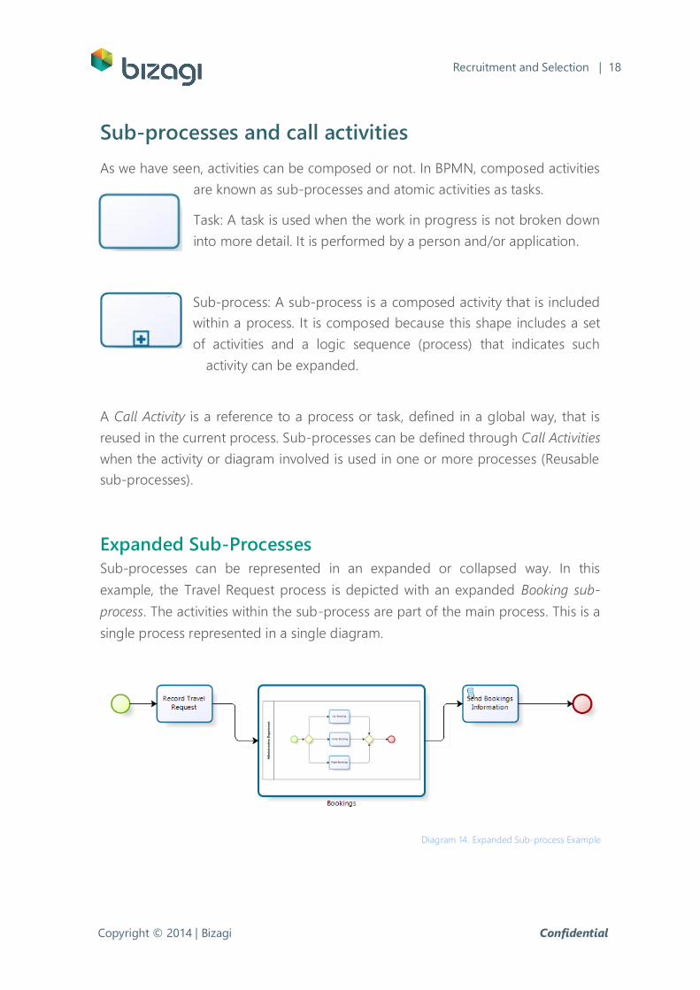
Expanded Sub-Processes
Sub-processes can be represented in an expanded or collapsed way. In this
example, the Travel Request process is depicted with an expanded Booking sub-
process. The activities within the sub-process are part of the main process. This is a
single process represented in a single diagram.
Diagram 14. Expanded Sub-process Example
Copyright © 2014 | Bizagi Confidential
Recruitment and Selection | 19
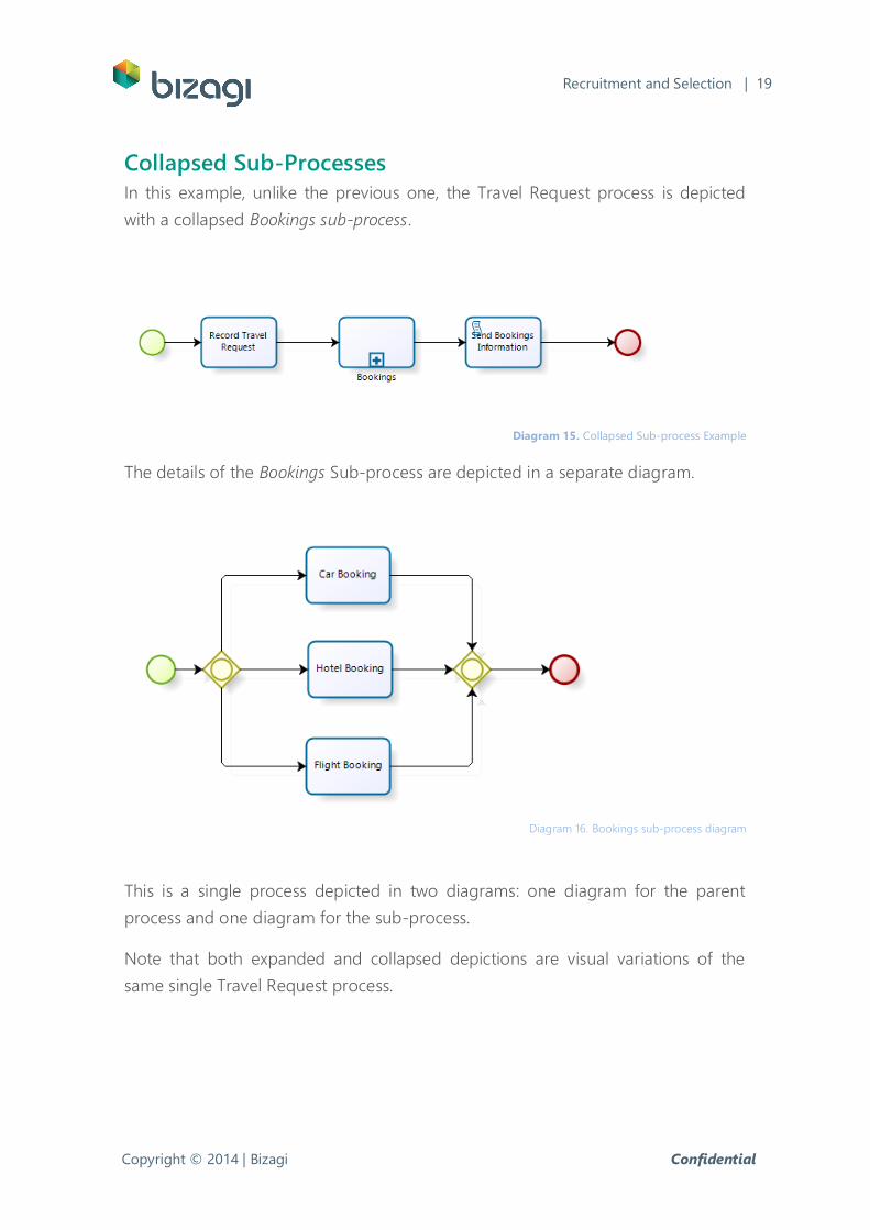
Collapsed Sub-Processes
In this example, unlike the previous one, the Travel Request process is depicted
with a collapsed Bookings sub-process.
Diagram 15. Collapsed Sub-process Example
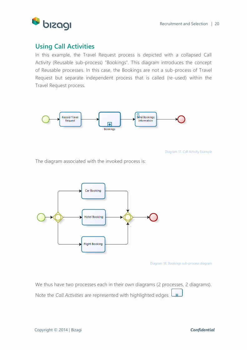
The details of the Bookings Sub-process are depicted in a separate diagram.
Diagram 16. Bookings sub-process diagram
This is a single process depicted in two diagrams: one diagram for the parent
process and one diagram for the sub-process.
Note that both expanded and collapsed depictions are visual variations of the
same single Travel Request process.
Copyright © 2014 | Bizagi Confidential
Recruitment and Selection | 20
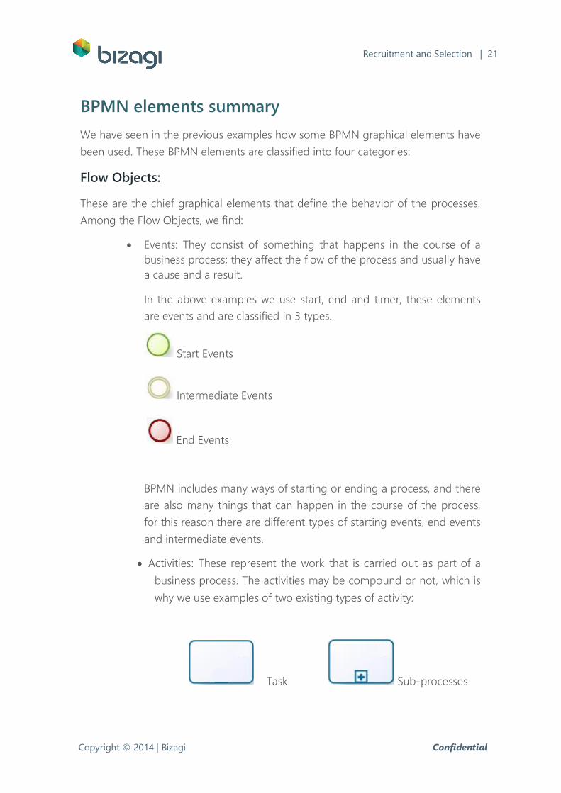
Using Call Activities
In this example, the Travel Request process is depicted with a collapsed Call
Activity (Reusable sub-process) “Bookings”. This diagram introduces the concept
of Reusable processes. In this case, the Bookings are not a sub-process of Travel
Request but separate independent process that is called (re-used) within the
Travel Request process.
Diagram 17. Call Activity Example
The diagram associated with the invoked process is:
Diagram 18. Bookings sub-process diagram
We thus have two processes each in their own diagrams (2 processes, 2 diagrams).
Note the Call Activities are represented with highlighted edges
Copyright © 2014 | Bizagi Confidential
Recruitment and Selection | 21
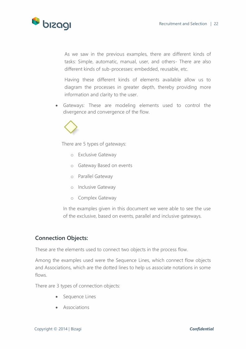
BPMN elements summary
We have seen in the previous examples how some BPMN graphical elements have
been used. These BPMN elements are classified into four categories:
Flow Objects:
These are the chief graphical elements that define the behavior of the processes.
Among the Flow Objects, we find:
Events: They consist of something that happens in the course of a
business process; they affect the flow of the process and usually have
a cause and a result.
In the above examples we use start, end and timer; these elements
are events and are classified in 3 types.
Start Events
Intermediate Events
End Events
BPMN includes many ways of starting or ending a process, and there
are also many things that can happen in the course of the process,
for this reason there are different types of starting events, end events
and intermediate events.
Activities: These represent the work that is carried out as part of a
business process. The activities may be compound or not, which is
why we use examples of two existing types of activity:
Task Sub-processes
Copyright © 2014 | Bizagi Confidential
Recruitment and Selection | 22
As we saw in the previous examples, there are different kinds of
tasks: Simple, automatic, manual, user, and others- There are also
different kinds of sub-processes: embedded, reusable, etc.
Having these different kinds of elements available allow us to
diagram the processes in greater depth, thereby providing more
information and clarity to the user.
Gateways: These are modeling elements used to control the
divergence and convergence of the flow.
There are 5 types of gateways:
o Exclusive Gateway
o Gateway Based on events
o Parallel Gateway
o Inclusive Gateway
o Complex Gateway
In the examples given in this document we were able to see the use
of the exclusive, based on events, parallel and inclusive gateways.
Connection Objects:
These are the elements used to connect two objects in the process flow.
Among the examples used were the Sequence Lines, which connect flow objects
and Associations, which are the dotted lines to help us associate notations in some
flows.
There are 3 types of connection objects:
Sequence Lines
Associations
Copyright © 2014 | Bizagi Confidential
Recruitment and Selection | 23
Message Lines
Swim Lanes:
These are elements used to organize flow activities in different visual categories
which represent functional areas, roles or responsibilities.
Pools
Lanes
Artifacts:
Artifacts are used to provide additional information about the process.
In the examples some notations were used in the flow.
There are three types:
Data Objects
Groups
Annotations
Copyright © 2014 | Bizagi Confidential
Recruitment and Selection | 24
If you wish to practice what you have learned, download bizagi’s Free
Process Modeler at:
http://www.bizagi.com/en/bpm-suite/products/modeler
For more information please refer to:
Mr White Introductory BPMN Document
http://www.omg.org/bpmn/Documents/Introduction_to_BPMN.pdf
BPMN Specifications at:
http://www.omg.org/bpmn/Documents/BPMN_1-1_Specification.pdf


![[uengine.org] (Eng) uEngine BPM Product Intro(uEngine3.5 Suite)](https://img.pdfslide.us/doc/110x75/549259e7b479593d4d8b45b9/uengineorg-eng-uengine-bpm-product-introuengine35-suite.jpg)