Embed Size (px)
Citation preview
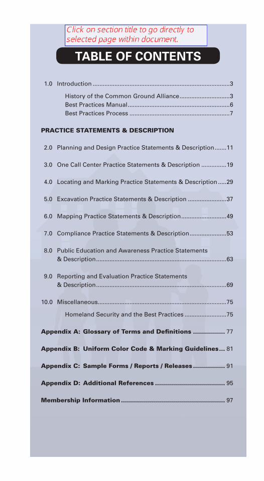
1.0 Introduction ..................................................................................3
History of the Common Ground Alliance ..............................3 Best Practices Manual .............................................................6 Best Practices Process ............................................................7
PRACTICE STATEMENTS & DESCRIPTION
2.0 Planning and Design Practice Statements & Description .......11
3.0 One Call Center Practice Statements & Description ...............19
4.0 Locating and Marking Practice Statements & Description .....29
5.0 Excavation Practice Statements & Description .......................37
6.0 Mapping Practice Statements & Description ...........................49
7.0 Compliance Practice Statements & Description ......................53
8.0 Public Education and Awareness Practice Statements & Description ..............................................................................63
9.0 Reporting and Evaluation Practice Statements & Description ..............................................................................69
10.0 Miscellaneous .............................................................................75
Homeland Security and the Best Practices .........................75
Appendix A: Glossary of Terms and Defi nitions ................ 77
Appendix B: Uniform Color Code & Marking Guidelines ... 81
Appendix C: Sample Forms / Reports / Releases ................ 91
Appendix D: Additional References ................................... 95
Membership Information .................................................... 97
TABLE OF CONTENTS
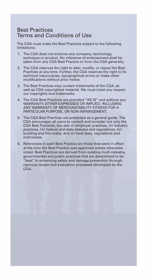
Best PracticesTerms and Conditions of UseThe CGA must make the Best Practices subject to the following limitations:
1. The CGA does not endorse any company, technology, technique or product. No inference of endorsement shall be taken from any CGA Best Practice or from the CGA generally.
2. The CGA reserves the right to alter, modify, or repeal the Best Practices at any time. Further, the CGA reserves the right to fi x technical inaccuracies, typographical errors or make other modifi cations without prior notice.
3. The Best Practices may contain trademarks of the CGA, as well as CGA copyrighted material. We must insist you respect our copyrights and trademarks.
4. The CGA Best Practices are provided “AS IS” and without any WARRANTY, EITHER EXPRESSED OR IMPLIED, INCLUDING ANY WARRANTY OF MERCHANTABILITY FITNESS FOR A PARTICULAR PURPOSE, OR NON-INFRINGEMENT.
5. The CGA Best Practices are presented as a general guide. The CGA encourages all users to consult and consider not only the CGA Best Practices, but also (i) employer practices, (ii) industry practices, (iii) federal and state statutes and regulations, (iv) building and fi re codes, and (v) local laws, regulations and ordinances.
6. References in each Best Practice are those that were in effect at the time the Best Practice was approved unless otherwise noted. Best Practices are derived from existing multi-industry, governmental and public practices that are determined to be “best” in enhancing safety and damage prevention through rigorous review and evaluation processes developed by the CGA.
Practice Statements & Description 3
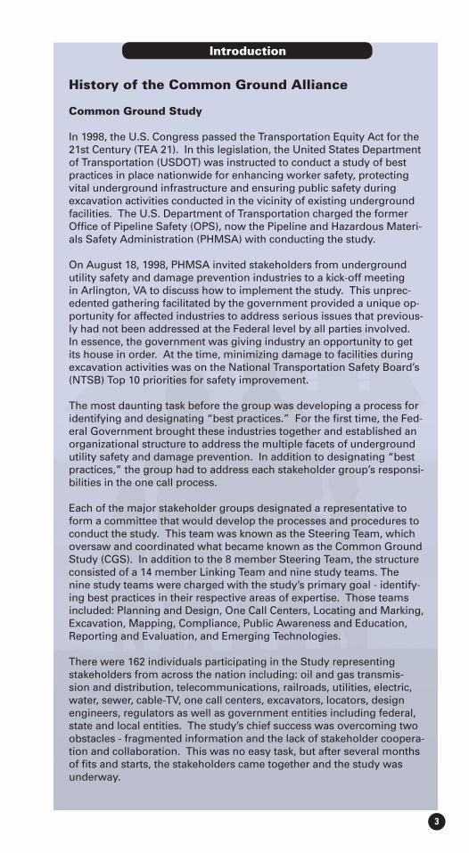
History of the Common Ground Alliance
Common Ground Study
In 1998, the U.S. Congress passed the Transportation Equity Act for the 21st Century (TEA 21). In this legislation, the United States Department of Transportation (USDOT) was instructed to conduct a study of best practices in place nationwide for enhancing worker safety, protecting vital underground infrastructure and ensuring public safety during excavation activities conducted in the vicinity of existing underground facilities. The U.S. Department of Transportation charged the former Offi ce of Pipeline Safety (OPS), now the Pipeline and Hazardous Materi-als Safety Administration (PHMSA) with conducting the study.
On August 18, 1998, PHMSA invited stakeholders from underground utility safety and damage prevention industries to a kick-off meeting in Arlington, VA to discuss how to implement the study. This unprec-edented gathering facilitated by the government provided a unique op-portunity for affected industries to address serious issues that previous-ly had not been addressed at the Federal level by all parties involved. In essence, the government was giving industry an opportunity to get its house in order. At the time, minimizing damage to facilities during excavation activities was on the National Transportation Safety Board’s (NTSB) Top 10 priorities for safety improvement.
The most daunting task before the group was developing a process for identifying and designating “best practices.” For the fi rst time, the Fed-eral Government brought these industries together and established an organizational structure to address the multiple facets of underground utility safety and damage prevention. In addition to designating “best practices,” the group had to address each stakeholder group’s responsi-bilities in the one call process.
Each of the major stakeholder groups designated a representative to form a committee that would develop the processes and procedures to conduct the study. This team was known as the Steering Team, which oversaw and coordinated what became known as the Common Ground Study (CGS). In addition to the 8 member Steering Team, the structure consisted of a 14 member Linking Team and nine study teams. The nine study teams were charged with the study’s primary goal - identify-ing best practices in their respective areas of expertise. Those teams included: Planning and Design, One Call Centers, Locating and Marking, Excavation, Mapping, Compliance, Public Awareness and Education, Reporting and Evaluation, and Emerging Technologies.
There were 162 individuals participating in the Study representing stakeholders from across the nation including: oil and gas transmis-sion and distribution, telecommunications, railroads, utilities, electric, water, sewer, cable-TV, one call centers, excavators, locators, design engineers, regulators as well as government entities including federal, state and local entities. The study’s chief success was overcoming two obstacles - fragmented information and the lack of stakeholder coopera-tion and collaboration. This was no easy task, but after several months of fi ts and starts, the stakeholders came together and the study was underway.
Introduction
Best Practices Version 8.04
Major lessons learned during the Common Ground Study were that communication is the key to ensuring safety and protecting vital facili-ties, and free-fl ow communication allows all stakeholders to focus on the common goals for safety and damage prevention. Another key element was that cooperation is essential and it works as proven by the success of the study.
One of the most controversial elements of the process for determin-ing a “best practice” was the use of the consensus process. For a practice to become a “best practice” all stakeholder groups must agree that they could live with the practice; if one group disagreed the practice would not become a “best practice.” It was realized early on that the fi nal product would not stand unless all stakehold-ers agreed with the content. To this day consensus is used by CGA committees and in identifying “best practices.” This single element of the process is what arguably gives the CGA and the “best prac-tices” document its integrity and ensures all elements of an issue are vetted comprehensively. The consensus process also proved, and continues to prove, that all stakeholders can reach consensus on the best practices to enhance safety and prevent damages.
In July 1999, eleven months after the kick-off meeting in Arlington, and after many intense meetings throughout the country, the Com-mon Ground Study which identifi ed and validated over 130 “best practices” to enhance safety and prevent damages to underground facilities was presented to the Secretary of Transportation.
Establishment of the Common Ground AllianceAfter the Common Ground Study was presented to the Secretary, and with the support of Senator Majority Leader Trent Lott who recognized the importance of this document, it was decided that the work of the Common Ground Study should be continued and the Best Practices document should become a living document. PHMSA was asked to facilitate and sponsor what became known as the Damage Prevention Path Forward. On June 15, 2000, the work of the team was completed when the Common Ground Alliance received its Certifi cate of Incorporation from the District of Columbia.
When established, the purpose of the Common Ground Alliance was to prevent damage to underground infrastructure and increase safety by fostering a sense of shared responsibility for the protection of underground facilities; support research development; conduct public awareness and education programs; identify and disseminate stakeholder best practices; and serve as a clearinghouse for damage data collection analysis and dissemination. The organization’s motto was and continues to be “Damage Prevention is a Shared Responsi-bility.”
CGA TodayThere are currently 16 stakeholder seats on the CGA Board of Direc-tors: electric, engineering/design, equipment manufacturing, ex-cavator, gas transmission, gas distribution, insurance, locator, one call center, oil, public works, railroad, road builder, state regulator, emergency services and telecommunications.

Practice Statements & Description 5
The CGA consists of working committees populated by the general membership. Those committees include Best Practices, Technology, Educational Programs, Data Reporting and Evaluation, Regional Partner and One Call Systems International.
Even though any CGA member can participate in committee discussions, a “Primary” is designated for each stakeholder group by its respective member on the Board of Directors. The Primary’s responsibility is to act as a spokesperson for their stakeholder group and participate in consensus decisions when necessary. This ensures that each stakeholder group has an equal say in the outcome of committee work, decisions and products.
The Common Ground Study and establishment of the CGA have given underground utility safety and damage prevention a home. The CGA is a central clearinghouse for disseminating best prac-tices, products and information that enhance safety and keep dam-ages to underground facilities to an ultimate minimum.
Since the founding of the CGA, damages to underground facili-ties during excavation activities was removed from the NTSB’s Top 10, 811 was implemented and is promoted by the CGA, the Locate Accurately campaign was nationalized and the Dig Safely campaign continued its successful implementation. The Damage Information Reporting Tool (DIRT) was developed and established as the long awaited repository of data that helps to identify the root cause of incidents that occur as a result in breakdowns in the one call process. In addition, the Best Practices document is con-sidered the “go to” resource by all stakeholders, governments and associated industries when addressing safety and damage preven-tion issues internally, as well as on the local, state and national levels.
With Best Practices 8.0, we continue to celebrate years of positive, effective, and successful cooperation in bettering our underground utility safety and damage prevention programs. The birth of CGA led to major accomplishments within the area of damage preven-tion that can be directly attributed to the work and success of our organization.
Best Practices Version 8.06
Best Practices Manual
The Best Practices Committee developed the following guide based on the Common Ground Study that includes the primary section with Practice Statements & Descriptions as well as Appendices A through D. The verbatim restatement of all ancillary material contained in the original Study is available on the CGA web site and is intended as an historical reference point for those persons interested in a more detailed background of the Best Practices.
The stakeholders involved with the original Common Ground Study never intended that the Best Practices would constitute a static model, rather that it be a working document that would evolve over time as more was learned and as technology advanced. In addi-tion, the CGA anticipated that there likely would be additional best practices developed by the interested participants. As best practices are added or amended, the changes are refl ected in subsequent ver-sions, numbered sequentially. By this means we hope to provide a continuum that will permit the stakeholders in underground safety and utility damage prevention as well as the public to see the course of development over time.
Best Practices 8.0 - New Practices & Modifi cations
The CGA added and amended multiple practices during 2010 that appear in Version 8.0. The following modifi cations were approved by the Best Practices Committee and CGA Board in 2010:
the Practice Statement that emphasizes generating the “minimum number of locates request updates necessary for the duration of the project.”
A new defi nition for Vacuum Excavation was included within the Glossary.
method of identifying facility locations.
ditional clarifi cation on Tolerance Zone on page 79 and a modifi ca-tion to item 2a within the “Guideline for Operator’s Facility Field Delineation.”
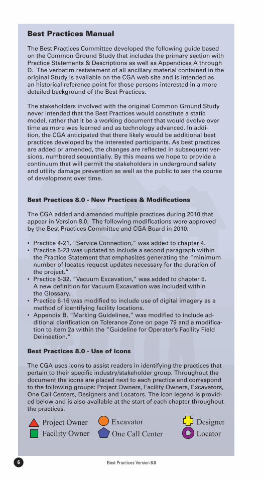
Best Practices 8.0 - Use of Icons
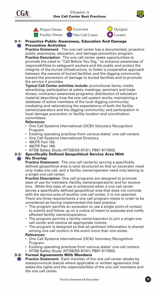
The CGA uses icons to assist readers in identifying the practices that pertain to their specifi c industry/stakeholder group. Throughout the document the icons are placed next to each practice and correspond to the following groups: Project Owners, Facility Owners, Excavators, One Call Centers, Designers and Locators. The icon legend is provid-ed below and is also available at the start of each chapter throughout the practices.
Practice Statements & Description 7
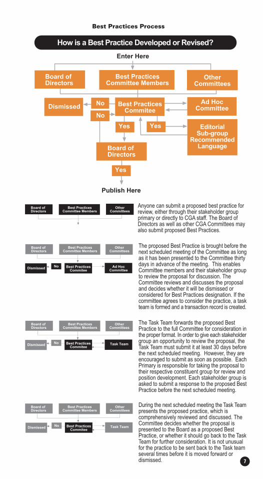
Best Practices Process
Board ofDirectors
Best PracticesCommittee Members
OtherCommittees
Dismissed Best PracticesCommitee
EditorialSub-group
RecommendedLanguage
How is a Best Practice Developed or Revised?
No
No
Board ofDirectors
Yes Yes
Ad HocCommittee
Yes
During the next scheduled meeting the Task Teampresents the proposed practice, which iscomprehensively reviewed and discussed. TheCommittee decides whether the proposal ispresented to the Board as a proposed BestPractice, or whether it should go back to the TaskTeam for further consideration. It is not unusualfor the practice to be sent back to the Task teamseveral times before it is moved forward ordismissed.
Anyone can submit a proposed best practice forreview, either through their stakeholder groupprimary or directly to CGA staff. The Board ofDirectors as well as other CGA Committees mayalso submit proposed Best Practices.
The proposed Best Practice is brought before thenext scheduled meeting of the Committee as longas it has been presented to the Committee thirtydays in advance of the meeting. This enablesCommittee members and their stakeholder groupto review the proposal for discussion. TheCommittee reviews and discusses the proposaland decides whether it will be dismissed orconsidered for Best Practices designation. If thecommittee agrees to consider the practice, a taskteam is formed and a transaction record is created.
The Task Team forwards the proposed BestPractice to the full Committee for consideration inthe proper format. In order to give each stakeholdergroup an opportunity to review the proposal, theTask Team must submit it at least 30 days beforethe next scheduled meeting. However, they areencouraged to submit as soon as possible. EachPrimary is responsible for taking the proposal totheir respective constituent group for review andposition development. Each stakeholder group isasked to submit a response to the proposed BestPractice before the next scheduled meeting.
Enter Here
Publish Here
Board ofDirectors
Best PracticesCommittee Members
OtherCommittees
Dismissed Best PracticesCommitee
No Ad HocCommittee
Board ofDirectors
Best PracticesCommittee Members
OtherCommittees
Dismissed Best PracticesCommitee
No
Board ofDirectors
Best PracticesCommittee Members
OtherCommittees
Task Team
Dismissed Best PracticesCommitee
No
Board ofDirectors
Best PracticesCommittee Members
OtherCommittees
Task Team
Best Practices Version 8.08
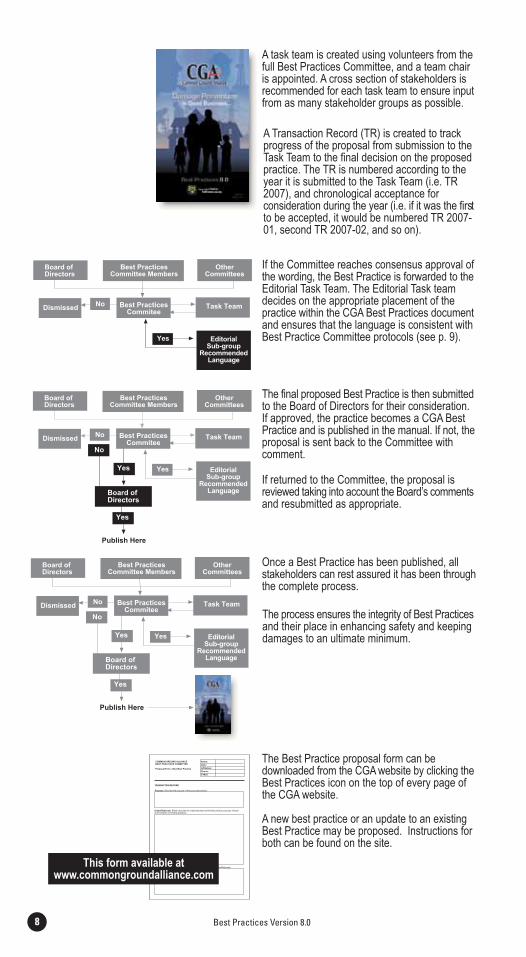
The Best Practice proposal form can bedownloaded from the CGA website by clicking theBest Practices icon on the top of every page ofthe CGA website.
A new best practice or an update to an existingBest Practice may be proposed. Instructions forboth can be found on the site.
If the Committee reaches consensus approval ofthe wording, the Best Practice is forwarded to theEditorial Task Team. The Editorial Task teamdecides on the appropriate placement of thepractice within the CGA Best Practices documentand ensures that the language is consistent withBest Practice Committee protocols (see p. 9).
A task team is created using volunteers from thefull Best Practices Committee, and a team chairis appointed. A cross section of stakeholders isrecommended for each task team to ensure inputfrom as many stakeholder groups as possible.
A Transaction Record (TR) is created to trackprogress of the proposal from submission to theTask Team to the final decision on the proposedpractice. The TR is numbered according to theyear it is submitted to the Task Team (i.e. TR2007), and chronological acceptance forconsideration during the year (i.e. if it was the firstto be accepted, it would be numbered TR 2007-01, second TR 2007-02, and so on).
The final proposed Best Practice is then submittedto the Board of Directors for their consideration.If approved, the practice becomes a CGA BestPractice and is published in the manual. If not, theproposal is sent back to the Committee withcomment.
If returned to the Committee, the proposal isreviewed taking into account the Board’s commentsand resubmitted as appropriate.
Once a Best Practice has been published, allstakeholders can rest assured it has been throughthe complete process.
The process ensures the integrity of Best Practicesand their place in enhancing safety and keepingdamages to an ultimate minimum.
EditorialSub-group
RecommendedLanguage
Yes
Dismissed Best PracticesCommitee
No
Board ofDirectors
Best PracticesCommittee Members
OtherCommittees
Task Team
Board ofDirectors
Yes
Yes
Publish Here
No
EditorialSub-group
RecommendedLanguage
Yes
Dismissed Best PracticesCommitee
No
Board ofDirectors
Best PracticesCommittee Members
OtherCommittees
Task Team
Board ofDirectors
Yes
Yes
Publish Here
No
EditorialSub-group
RecommendedLanguage
Yes
Dismissed Best PracticesCommitee
No
Board ofDirectors
Best PracticesCommittee Members
OtherCommittees
Task Team
This form available atwww.commongroundalliance.com
Practice Statements & Description 9
Guide to Editorial Task Team Procedures
1. The Editorial Task Team is a task force of the Best Practices (BP) Committee. As such it acts consistent with the BP Committee’s instructions.
2. While the team may edit punctuation, grammar, organization and display, the team does not make substantive changes to best prac-tices or best practice descriptions; however, any editorial changes are reported back to the BP Committee for review and comment.
3. The team receives input from the BP Committee in one of three ways:
a) when it receives a best practice that has been adopted, b) when it is instructed by the BP Committee to make non-substantive changes to the BP practice description, or c) when it makes the changes indicated in 2, above, presents them to the BP Committee, and receives feedback thereafter.
4. Editorial changes noted in 3b, above, are only those that the BP Committee first determines are not substantive alterations to the best practice. They are dealt with in the same manner as a best practice, in that BP Committee members must agree by consensus, but they are not referred to the CGA board for adoption, as would be the case for a new or amended best practice.
Feedback & Proposed Modifications
The CGA welcomes comments and suggestions on improving the format and updating the content of the best practices. Our intent is to make the statement of best practices as easy to use as possible. To submit a comment or to propose a new practice or practice modifi-cation, contact the CGA office (703-836-1709) to request a proposal form or visit the CGA web site at www.commongroundalliance.com. The proposal form can be downloaded from the web site by clicking on the best practices tab at the top of the home page and clicking the link to “New Practice & Process Review” at the bottom of the page.

Best Practices Version 8.010
For additional information on the Common Ground Alliance or to learn how to become a member, visit the CGA web site at
www.commongroundalliance.com

Practice Statements & Description 11
2-1: Plat Designation Of Existing Underground Facility Easements Practice Statement: Plats prepared for the development of real prop-
erty identify and show the alignment of any existing buried facilities and the presence and extent of any existing easements and/or Rights of Way.1
Practice Description: Various items are required on the plats filed prior to the development of lands. Where plats are required to be filed, the items required include the identification of the easements of underground facilities traversing the land described on the plat. Identification of easements of underground facilities on the plat increases notice to developers and the public about the existence of the underground facilities. Notification to the owners of underground facilities that a plat has been filed alerts underground facility owners/ operators to establish communication between the developers and the operators to facilitate a plan and design for the use of the land which complements the underground facility. Benefits: Often underground facility owners/operators do not receive notice of developments impacting their facilities until excava- tion activity has commenced. This compromises the optimal use of the land and potentially compromises the integrity of the under- ground facility. Reference:
2-2: Gathering Information For Design Purposes Practice Statement: The designer uses all reasonable means of obtaining information about underground facilities in the area of the planned excavation. Practice Description: During the planning phase of the project, all
available information is gathered from facility owners/operators. This includes maps of existing, abandoned and out-of-service facili-
ties, cathodic protection and grounding systems, as-builts of facilities in the area if the maps are not current, proposed project designs, and schedules of other work in the area. This information is gathered for the purpose of route selection and preliminary neighborhood impacts, and as part of the process of impact analysis when evaluat-ing different design possibilities. Methods of gathering information may include contacting a one call center, facility owners/operators, coordinating committees/councils, other designers, engineering so-cieties, and governmental agencies as a means of identifying under-ground facility owners/operators in an excavation area. Gathering information may also include a review of the site for above ground indications of underground facilities (i.e. permanent signs or markers, manhole covers, vent pipes, pad mounted devices, riser poles, power and communication pedestals and valve covers). The one call center provides a listing of operators directly to the designer, or to the designer’s subsurface utility engineer. This information is available in formats that are accessible to all users such as voice, fax, E-mail or web-site. Once identified, the designer contacts the operators directly or uses the one call system. The facility owner/operator may locate their underground facilities or provide locations of their
underground facilities to the designer by other means, such as by marking up design drawings or providing facility records to the
designer. Benefits: Gathering underground facility information and including this information in the planning phase minimizes the hazards, cost and work to produce the final project.1 TR-2007-01: Modification to Statement Approved by CGA Board on August 24, 2007.
Chapter 2Planning and Design Best Practices
Best Practices Version 8.012
References:
Planning and Design.”
dated Edison, New York, New York, June 9, 1997.
(FHWA), February 1999, Office of Program Administration (HIPA).
Manual, Document No.: 710-020-001-d, Section 11.4, January 1999.2-3: Identifying Existing Facilities In Planning And Design Practice Statement: Designers indicate existing underground facilities on drawings during planning and design. Practice Description: During the planning phase of the project, existing facilities are shown on preliminary design plans. The planning documents include possible routes for the project together with known underground facility information. The various facility owners/operators are then given the opportunity to provide appropriate feedback. During the design phase of the project, underground facility information from the planning phase is shown on the plans. If information was gathered from field located facilities, from underground facility surveys or from subsurface utility engineering, this is noted on the plans. The designer and the contractor both know the quality of the information included on the plans. If an elevation was determined during the information gathering, it is shown on the plan. The facilities shown include active, abandoned, out-of-service, and proposed facilities. The design plans include a summary drawing showing the proposed facility route or excavation including streets and a locally accepted coordinate system. The plans are then distributed to the various facility owners/ operators to provide the opportunity to furnish additional information, clarify information, or identify conflicts. Benefits: Providing complete underground facility information and including this information on design drawings reduces the hazards, simplifies coordination and minimizes the cost to produce the final project.2-4: Utility Coordination Practice Statement: Project owners and facility owners/operators regularly communicate and coordinate with each other concerning future and current projects. Practice Description: Utility coordination fosters an open exchange of information among private and public facilities, govern mental agencies and construction related organizations. Utility coordination also promotes cooperation among said groups in the planning, design and construction of projects affecting the overall good of participating parties, their organizations and customers or constituents, and the general public. Utility Coordinating Committees (or Councils) include private utilities, public agency utilities, engineer- ing firms, contractor associations, and others with facilities or business interests in public rights-of-way. Coordinating Committees function in multiple communities, counties and states/provinces to promote excavation project coordination. Typical items of discussion include facility excavations in existing and recently paved roadways, disruption of essential facility services, location of utility facilities, environmental impact of damages to utilities, permit procedures, right-of-way access controls and underground facility damage prevention. Plans of future roadway improvement and of future facility installations are reviewed regularly.
Practice Statements & Description 13
References:
Relocations.”
ment/Project Guide, December 1996.
June 1993.2-5: Markers For Underground Facilities Practice Statement: The presence and type of underground facilities are indicated by permanent above and below ground markers and material. Practice Description: A combination of above ground and below ground markers is used to identify and locate underground facilities. The purpose of above ground markers is to identify underground facilities, not to locate for excavation or circumvent the one call process. However, designing underground facilities for future location reduces the risk of an incorrectly marked underground facility during an excavation project. Above ground markers are developed during the design process and include the company name, type of facility, emergency contact, and the one call number. The locations and types of markers are specified in the construction plans. The design provides a marker system to include, but not limited to, stream crossings, public road crossings, other facilities’ right-of- ways, railroad crossings, heavy construction areas, and any other location where it is necessary to identify the underground facility location. If non-detectable facilities are being installed, the design includes a means to accurately locate the underground facility from the surface. The facility is color-coded in accordance with the APWA guidelines to assist in identifying the particular facility. Road decals, stencils, tracer tapes, electronic markers or other appropriate systems may mark areas where traditional markers are considered impractical. Benefits: Provisions to aid in future locating requests are included in the design. In addition, an effective marker system is beneficial to the underground facility owner/operator and first responders to an area involving more than one underground facility or an incident near underground facilities. References:
Underground Facilities.”2-6: Follow All Applicable Codes, Statutes And Facility Owner/operator Standards Practice Statement: When planning and designing the installation of new or replacements of existing underground facilities, the designer follows all federal, state/provincial and local guidelines, codes, statutes and other facility owner/operator standards. Practice Description: The designer of a facility project typically considers only national industry codes, regulations and practices applicable to that particular facility, and not of adjacent facilities. Regulations, codes, standards and other design documents generally specify depth of cover, and horizontal and vertical clearances between adjacent facilities. However, they are not always prescrip- tive and can be subject to interpretation by the designer. In addition, certain codes allow exceptions to the prescribed minimum clearances, contingent upon approval between the affected facility owners/operators. The designer also has to consider the protection and temporary support of adjacent facilities, and any interference to existing cathodic protection and grounding systems. Consequently, the designer has to provide specifications on safety measures to be taken and procedures for emergency notification and repairs in the case of any damage to an adjacent facility. Designers are aware of proposed and revised standards and codes that may affect the project.
Best Practices Version 8.014
Benefits: The designer reviewing codes pertaining to adjacent facilities minimizes any potential conflict of code clearance require- ments, and facilitates future locating efforts.2-7: Use Of Qualified Contractors Practice Statement: Qualified contractors are used to excavate on and near underground facilities. Practice Description: Contractors that excavate on and near underground facilities possess the qualifications necessary to conduct such activities in a manner that is skillful, safe and reliable. The requisite qualification of the contractor serves to protect the public and integrity of underground facilities in the vicinity of the excavation. Using qualified contractors ensures that all contractors who bid and work on a project employ safe work habits and are capable of performing the requested work. When working with contractors, the project owner is familiar with the contractors’ work experiences and financial abilities and should not ask the contractors to bid beyond their capabilities. Allowing a competitive bidding process from qualified and competent contractors will assure the best quality and pricing available, while reducing damages to under- ground facilities. Benefits:
References:
Department of Transportation, Chapter 14-22.
2-8: Mandatory Pre-bid Conferences Practice Statement: A mandatory pre-bid conference is held and bids are only accepted from attending contractors. Practice Description: Depending on the level of impact of proposed construction upon facilities in the excavation area, the project owner or project designer requires potential contractors to attend a mandatory pre-bid conference including underground facility owners/operators. This pre-bid conference is exercised to discuss, among other things, the particular facilities in the area and the requirements to properly protect, support, and safely maintain the facilities during excavation. Official minutes are taken and disseminated as written to all attendees. Benefits: Pre-bid conferences provide a forum for the contractor, owner and other interested parties to discuss a project and record binding changes or clarifications to the scope of the project. The pre- bid conference also provides an opportunity for all parties to review contract documents, regulatory requirements, schedules and submit- tal formats. Most large projects involve multiple levels of subcon- tracting activity, as well as multi-layered regulatory oversight. The pre-bid conferences traditionally address these issues in an open forum so that all bidders are equally aware of the ground rules. The ground rules would be both commercial and technical in nature, covering the spectrum from performance bonds to safety practices. References:
2-9: Continuous Interface Between The Designer And Potential Contractors During The Pre-bid/bid Phase Practice Statement: Once a project design is completed, the designer participates in the pre-bid/bid process. Practice Description: The designer’s continuing involvement during the pre-bid/bid phase with the potential contractor(s) allows for more effective communications between all parties. The designer can assess whether the interested bidders have the expertise needed and the correct understanding of the intended design.
Practice Statements & Description 15
2 TR-2001-04: Amendment Approved by CGA Board on September 25, 2003.
Benefits:
safety concerns and delays to project completion.
readily shown on the plans, such as accommodations of facility adjustments required to construct the project. References:
2-10: Continuous Interface Between The Designer And The Contractor During The Construction Phase Practice Statement: The designer continues to interface with the selected contractor throughout the construction phase. Practice Description: This practice allows the designer to be available for pre-construction conferences, unforeseen conditions and design changes and post-construction conferences. Benefits:
minimizing subsequent modifications to the project design, costs and completion.
also facilitated. Reference:
2-11: As-built Drawings Practice Statement: As-built drawings are prepared and the information recorded to aid future excavations and locates. Practice Description: Installation should be made in accordance with the approved construction plans; any deviation to the plans is documented and such changes indicated on the as-built drawings. As-built information is recorded, retained and made available for subsequent excavation. Benefits: As-built drawings serve as an information source for future projects to minimize damage to existing facilities. References:
2-12: Supply Line Separation When installing new direct buried supply facilities in a common trench, a minimum or 12 inch radial separation should be maintained between supply facilities such as steam lines, plastic gas lines, other fuel lines, and direct buried electrical supply lines. If 12 inches separation cannot be feasibly attained at the time of installation, then mitigating measures should be taken to protect lines against damage that might result from proximity to other structures. Examples may include the use of insulators, casing, shields or spacers. If there is a conflict among any of the applicable regulations or standards regard- ing minimum separation, the most stringent should be applied.2 References:
2-13: Trenchless Excavation Practice Statement: All stakeholders adhere to all Best Practices and the following general guidelines prior to, during and after any trenchless excavation (as applicable): Practice Description:
make the determination to use trenchless excavation installation.
owners to design projects that maintain minimum radial clearances
Best Practices Version 8.016
between the new facility and existing facilities. Minimum clearances are equal to or greater than applicable standards.
The project owner and design engineer establish line and grade of the proposed excavation to maintain the established minimum clearances. (Additional Information: Refer to practices 4-19 & 5-29).3 References: See Appendix D2-14: Subsurface Utility Engineering (SUE) Practice Statement: When applied properly during the design
phase, SUE provides significant cost and damage avoidance benefits and the opportunity to correct inaccuracies in existing facility re-cords.4
Practice Description: In certain cases and environments, it may be difficult or impossible to determine the locations of all utilities and/or impediments with sufficient accuracy to avoid damage or delay during construction. In these cases, Subsurface Utility Engineering (SUE) is applied during the design phase to locate, identify and characterize all existing utility infrastructure (and other relevant non-utility features) found within a given project/area. SUE is applied in a structured manner, in accordance with practices and Quality Levels found in ASCE 38-02 “Standard Guideline for the Collection and Depiction of Existing Subsurface Utility Data.” The project owner dictates the required Quality Levels, as well as the amount of effort expended by the SUE provider on each. Although the Standard is more detailed and comprehensive, the following is a brief summary of the Quality Levels defined therein: QL-D involves utility records research and interviews with knowledgeable utility personnel. QL-C involves surface survey, identifying and recording aboveground features of subsurface utilities, such as manholes, valves, and hydrants. QL-B involves application of “surface geophysical methods,” such as EM-based locating instruments, GPR, Radar Tomography, metal detectors, and optical instruments, to gather and record approximate horizontal (and, in some cases, vertical) positional data. QL-A involves physical exposure via “soft-digging” (vacuum excavation or hand-digging), and provides precise horizontal and vertical positional data. SUE results are
integrated into the design process, where design engineers use the information to create construction plans that accommodate existing infrastructure, thereby reducing the overall risk of conflicts and/or damage.5
References: Cost
Savings on Highway Projects Utilizing Subsurface Utility Engineering. Pub. No. FHWA-IF-00-014.
Subsurface Utility Engineering: Enhancing Construction Activities. Pub. No. FHWA-IF-01-011.
Standard Guideline for the Collection and Depiction of Existing Subsurface Utility Data. Pennsylvania State Law2-15: Use of Qualified Designers Practice Statement: Project owners employ qualified design and SUE
providers. Practice Description: When new utility infrastructure is installed,
project owners employ qualified Designers and SUE providers. Such providers have knowledge and understanding of applicable CGA Best Practices and the ASCE 38-02 SUE Standard. Providers are qualified in application of the associated design practices and SUE process-es. The providers also are knowledgeable of the operation of any involved equipment and interpretation of results where applicable.
3 TR-2002-03: Amendment Approved by CGA Board on September 16, 2005.4 TR-2007-02: Modification to Statement Approved by CGA Board on August 24, 2007.5 TR-2004-03: Amendment Approved by CGA Board on March 4, 2005.
Practice Statements & Description 17
Use of qualified SUE providers provides higher quality information to designers, who in turn can minimize utility conflicts by better depict-ing actual subsurface conditions on the construction plans.6
Practice Statement 2-3: Identifying Existing Facilities in Planning and Design Practice Statement 2-7: Use of Qualified Contractors Practice Statement 2-14: Subsurface Utility Engineering References: Public Service Electric & Gas (PSE&G, New Jersey)2-16: Project Coordination7
Practice Statement: Large and/or Complex projects may require the use of specific processes established to enhance safety and coor-dinate buried facility damage prevention efforts among all poten-tially affected stakeholders throughout the life of the project. Such processes are intended to compliment, and be used in addition to, standard and customary one call notification and locating practices.
Description: A “Large/Complex” project is a single project or a series of repetitive small, related-scope, short-term projects which impact facilities over a long period of time or a large area. Such projects pose a unique set of safety and damage prevention challenges when using standard one call practices, specifically as they apply to ongoing locating and re-marking requirements. These unique chal-lenges can be addressed by the establishment of special processes, including, but not limited to: a method for identifying such projects; pre-planning and design coordination; increased one call center involvement; a formalized communication process among all affected stakeholders; project-specific marking agreements that address vari-ance scenarios; regularly scheduled meetings of, and on-going com-munication among, all involved stakeholders; and positive response. The purposes for establishing such processes are to enhance safety and optimize the utilization of locating resources on “Large/Complex” projects.
References:
GAUPC and Georgia Utility Facility Protection Act PA One Call and PA Underground Utility Line Protection Act
6 TR-2007-04: Amendment Approved by CGA Board on November 15, 2007.7 TR-2006-03: Amendment Approved by CGA Board on December 12, 2008.

Best Practices Version 8.018
For additional information on the Common Ground Alliance or to learn how to become a member, visit the CGA web site at
www.commongroundalliance.com
Practice Statements & Description 19
3-1: Proactive Public Awareness, Education And Damage Prevention Activities Practice Statement: The one call center has a documented, proactive public awareness, education, and damage prevention program. Practice Description: The one call center seeks opportunities to promote the need to “Call Before You Dig,” to enhance awareness of responsibilities to safeguard workers and the public and protect the integrity of the buried infrastructure, to foster a cooperative approach between the owners of buried facilities and the digging community toward the prevention of damage to buried facilities and to promote the service it provides. Typical Call Center activities include: promotional items; media advertising; participation at safety meetings; seminars and trade shows; contractor awareness programs; distribution of education material describing how the one call system works; maintaining a database of active members of the local digging community; mediating and rationalizing the expectations of both the facility owners/operators and the digging community; and participation in local damage prevention or facility location and coordination committees. References:
Program.
3-2: Specifically Defined Geopolitical Service Area With No Overlap Practice Statement: The one call center(s) serving a specifically defined geopolitical area is (are) structured so that an excavator need only make one call, and a facility owner/operator need only belong to a single one call center. Practice Description: One call programs are designed to promote ease of use for members (facility owners/operators) and for excava- tors. While this ease of use is enhanced when a one call center serves a specifically defined geopolitical area that does not coincide with the service area of another one call center, it is not essential. There are three requirements a one call program meets in order to be considered as having implemented this best practice:
to submit and follow up on a notice of intent to excavate and notify affected facility owners/operators.
call center and receive all appropriate notices.
among one call centers in the event more than one exists. References:
Program.
3-3: Formal Agreements With Members Practice Statement: Each member of the one call center abides by state/provincial statute where applicable or written agreement that states the rights and the responsibilities of the one call members and the one call center.
Chapter 3One Call Center Best Practices
Best Practices Version 8.020
Practice Description: Operating procedures and bylaws are established. Procedures for the operation of a one call center are simple. The concept is for service, not paperwork. Topics for procedures can be classified as: general, communications, center operations, reports, expenses and publicity. These topics could be expanded to include guidelines and whatever else is needed for a particular system. Bylaws vary, depending on the type of organiza- tion. In some instances they may prove unnecessary. If bylaws are adopted, simplicity is the key word. Items that could be incorporated include sections on membership (including rights), financial matters, meetings, elections and duties of officers. Any other agreements required are kept as simple as possible to facilitate understanding by all participants. Consideration is given to include “hold harmless” clauses, amounts of liability insurance, errors and omissions insurance, retention of records, cost allocations, reimbursements, area served (with options to expand as planned), and any special arrangements necessary. If an agreement to contract the service to an outside concern is made, it contains controls, checks and balances. References:
Program.
3-4: One Call Center Governance Practice Statement: The one call center is governed by a board of directors representing the diverse makeup of the constituent groups, for example facility owners/operators, designers, contractors/excava- tors, and government. Practice Description: To ensure that a one call center functions to the best benefit of the entire community, it is governed by a board of directors made up of representatives of the stakeholders. Board members are from a variety of industry types, such as facility owners/ operators, contractors, designers, project owners and government representatives. Each board member is knowledgeable in their own industry and of how it interacts with the one call center and all of the represented stakeholders. References:
Program.
3-5: Single Toll Free Statewide Number With Nationwide Access Practice Statement: The one call center(s) have a single toll free statewide number with nationwide access. Practice Description: There will be only one statewide toll free telephone number for the one call center(s) to receive locate requests. This number has nationwide access, meaning that a caller can reach the center(s) from anywhere in the country. References:
Program.
3-6: Hours Of Operation Practice Statement: The one call center can process locate requests 24 hours a day, 7 days per week. Practice Description: The one call center has in place a process where a caller, at anytime of the day or night, every day of the year, who has a locate request can contact the one call center and have that request processed.
Practice Statements & Description 21
References:
3-7: Voice Record Of All Incoming Calls Practice Statement: A voice recording is maintained of all voice transactions concerning requests to locate facilities. Practice Description: A voice recording of telephone communica- tions for locate requests is made to ensure a precise record of the activity is retained. This recording can be legally supported in court as well as used for damage investigations. References:
Program.
3-8: Retention Of Voice Records According To Applicable Statutes Practice Statement: Voice records of all calls concerning requests to locate facilities are kept in retention according to applicable statutes. Practice Description: Voice recordings are a factual record of the events that occurred between the caller and the one call center. These factual records must be maintained and accessible until the applicable statute of limitations in the state/province have expired Since these laws vary from state to state, no specific time period is set forth as best practice. In the absence of notice by some party to the contrary, after the expiration of the statute of limitations the records may be destroyed. The one call center has a procedure for processing requests for voice information. References:
Program.
3-9: Caller Feedback Practice Statement: The one call center provides the caller with the ticket number and the names of facility owners/operators who will be notified for each locate request. Practice Description: Providing the locate request number and the names of the facility owners/operators who will be notified enhances the efficiency of the one call process. When provided the names of the facility owners/operators, the excavator knows which owners operators will be notified in the area of the planned excavation. This helps the excavator determine if the facility owners/operators have responded to the locate request. References:
Program.
3-10: Printed Ticket Recall Practice Statement: The one call center can provide a printed copy of any ticket for a period of time determined by applicable statutes. Practice Description: In the event of a damage investigation, litigation, or other event, it is often necessary to have a hard copy printout of a location request ticket. Local governments have statutory requirements for record retention in such cases. The one call center has the ability to produce, as necessary, a copy of a location request ticket for the appropriate statutory period.
Best Practices Version 8.022
References:
Program.
3-11: Documented Operating Procedures, Human Resource Policies, And Training Manuals Practice Statement: The one call center has documented operat- ing procedures, human resource policies and training manuals. Practice Description: The one call center has documented operat- ing procedures, human resource policies, and training manuals. Training manuals, practices, procedures, and policies are on the premises in a designated area or place, dated, and available for reference. References:
Program.
3-12: Documented Owner Verification Of Data Submitted By Facility Owners/operators Practice Statement: The one call center returns the geographic description data base documentation to the facility owner/operator annually and after each change for verification and approval. Practice Description: The one call center can only work with the information related to the existence of buried facilities that its members provide. It is important that the one call center be able to produce evidence that a member’s data is accurate, according to that member. Regular verification of data is a part of the documented agreement or operating procedures between the owner or operator of buried facilities and the one call center. Any deletions or additions made by the member are entered into the data base and documenta- tion of the change sent back to the member for verification, prior to activation. References:
Program.
3-13: Flexibility For Growth And Change Practice Statement: The operating plan of the one call center is sufficiently flexible to accommodate growth and change. Practice Description: A successful one call center maintains flexibility to respond to changes by forming and maintaining a responsive organization whose Board of Directors’ composition allows adequate representation of the needs of all stakeholders. A Board’s ability to respond to change will be enhanced by drafting bylaws and operating procedures that reflect the current environment in which the one call center serves. The most successful Boards review these documents on an ongoing basis to make sure they continue to reflect or respond to current conditions. These Boards conduct regular strategic planning sessions during which they review the current state of the Center’s major systems, programs and outreach activities. Such assessments help them identify stakeholder needs for future growth and development. Many members of Boards and center management teams keep themselves informed about and involved in the one call industry by joining associations and attending conferences or other educational events that help them to better identify new opportunities for growth and change.
Practice Statements & Description 23
References:One Call Systems International (OCSI) Voluntary Recognition Program.
3-14: Meeting Between The Excavator And Facility Operator(s) Initiated By One Call Notification Practice Statement: The one call center has a process for receiv- ing and transmitting requests for meetings between the excavator and the facility operator(s) for the purpose of discussing locating facilities on large or complex jobs. Practice Description: The one call center relays requests for job site facility meetings for excavators who request them with facility owners/operators. If a meeting is required to show the limits and schedule of the work, the one call center indicates that a meeting is requested. The one call center requires that the excavator provide sufficient information to fully identify the boundaries of the proposed work site. A meeting request does not necessarily eliminate the need for a locate request. References:
3-15: One Call Center Accepts Notifications From Designers Practice Statement: The one call center accepts design requests and has the ability to process them as designated by the facility owners/operators. Practice Description: To facilitate damage prevention, project designers have a need for access to facility location information from facility owners/operators. If a design request is received, the one call center provides a listing of facility owners/operators directly to the designer. Once the list is identified, the one call center processes the request as designated by each facility owner/operator. References:
3-16: Locate Request Practice Statement: The one call center captures the following information, at a minimum, on a locate request: the caller’s name and phone number; the excavator’s/company’s name, address and phone numbers; the specific location of the excavation; the start date and time of the excavation; and the description of the excavation activity. Practice Description: A locate request is a communication between an excavator and one call center personnel in which a request for locating underground facilities is processed. In addition to the minimum information required in the practice statement (above), the locate request should include any information, if avail- able, that will help to establish the specific location of the excavation site. This additional information could include, for example: A. More detailed information to help determine the specific location of the excavation. Such information may include: 1. City 2. County/Parish/Township 3. State/Province 4. Street address 5. Street name 6. Length and direction of the excavation and the nearest adjacent cross streets (needed to bound area of excavation or extended excavation) 7. Subdivision and lot number (for new development) 8. Latitude/Longitude: Latitude-longitude coordinate(s) or specific address of the dig site may be done automatically by the GIS subsystem or determined by computer assisted customer service representative. The dig site can be a point, and area or
Best Practices Version 8.024
box, or a polygon. For a spatial rectangle (maximum/minimum latitude/longitude), the dig site must be wholly within the included area. 9. Highway mile markers 10. Railroad mileposts 11. General directions/instructions 12. Map grids 13. Distance to nearest cross-street 14. Any other pertinent references to help establish the location of the dig site B. The intended start date and time of the excavation (i.e., the date excavation is actually expected to begin, which may be later than when excavation can legally begin based on the ticket date). C. Type of the excavation activity (e.g., boring, blasting, trenching, trenchless, etc.) D. Who the excavation work is being done for E. What is the purpose of the work (i.e., what will be installed and or built) F. Additional remarks References:
3-17: Practices To Reduce Over-Notifications Practice Statement: The one call center employs practices designed specifically to reduce the number of notices transmitted to facility owners/operators, in which the reported excavation site is outside the owner’s/operator’s desired area of notification. Practice Description: The one call center employs technology that allows the facility owner/operator to determine its desired area of notification by either polygons or grids. To reduce over-notifications, technology includes but is not limited to:
to within approximately 800 feet; and
area of notification to within approximately 100 feet. References:
3-18: Disaster Recovery Practice Statement: A one call center develops, implements, and maintains an effective disaster recovery plan enabling the one call function to continue in the event of a disaster. Practice Description: The one call center develops and implements an effective disaster recovery plan enabling it to continue operations in the aftermath of a disaster affecting the facility. Excava- tors and underground facility owners/operators outside of the area affected by the disaster can continue to conduct business with minimum to no delays in the services provided by the one call center. The disaster recovery plan makes provisions for the one call center to process emergency locate requests for the areas affected by the disaster. The one call center (the primary center) has a backup arrangement with another facility at a remote location (the secondary center). This arrangement includes:
ready to be activated within minutes of the primary centers’ failure.
hardware with the primary center. The secondary center always has a copy of the primary’s current software.
database including locate requests on a regular basis, preferably real-time.
Practice Statements & Description 25
for the primary center’s operation at all times.
basis, the disaster recovery plan is implemented to verify that it is operational. References:
3-19: Direct Electronic Locate Practice Statement: The one call center provides users a means of direct, electronic entry of locate requests that maintain comparable ticket quality to an operator-assisted entry. Practice Description: The one call center has interactive data communications sufficient to permit remote data entry for members and excavators. The remote interface validates the input information and allows the user to make corrections if necessary. This correction is accomplished by referencing the same geographic database used at the one call center when taking a voiced-in request. This process ensures that the ticket quality is maintained for all tickets. References:
3-20: Accept Multiple Reference Points For Locate Requests Practice Statement: The one call center is able to accept multiple types of points of reference to define the exact location of an excava- tion site (i.e., latitude/longitude, highway/railroad/pipeline mile markers, address, street/cross-street, etc.). Practice Description: The one call center’s locate request taking processes and computer system are designed to accept and process multiple types of reference points used by callers to (1) describe the location of their work and (2) define the excavation site. Examples of different types of reference points include: highway mile markers, railroad mileposts, valid address or street-cross street, latitude longitude, township-range-section, city, county, political and mail address (zip code) boundaries, etc. All stakeholders involved in the one call process receive a corresponding benefit when the call center is able to define the excavation site as specifically as possible. The facility operator’s job of determining the existence of a potential conflict is expedited, field personnel can find and mark the affected area much easier, and the excavator receives timely markings covering the area of excavation. Standardizing on a limited set of criteria reduces the flexibility of the system to serve the excavator and facility owner/operator. The one call center invests in systems and processes that permit inclusion of a variety of types of reference points in defining the excavation site. The one call center takes steps to link these reference points to the database used to register the facility operator’s desired area of notification, thereby assisting in reducing over-notification. References:
3-21: One Call Center Security Practice Statement: The one call center provides appropriate physical and systems security, fire protection and electrical protection to protect the one call center and its critical components. Practice Description: The one call center needs protection from natural disasters and other threats. Since the one call center is a critical link in the communication chain between the excavating community and facilities, it is important that the one call center does whatever it can to provide adequate security, taking into account that it may well need to be operational in times of natural disasters or in the face of other threats. Security components could include:
Best Practices Version 8.026
operations areas, lighting, employee key cards, guard patrols.
include locating the facilities in locked enclosures and restricting access to necessary personnel.
property.
Call Center.
systems.
software. Reference:
3-22: Hardware Designed To Tolerate A Single Point Of Failure Practice Statement: The one call center uses fault tolerant hard- ware for its critical path operations, such as ticket taking, database access, and ticket delivery. Practice Description: A fault tolerant system can withstand any single hardware malfunction without any interruption or degradation of service. These systems have the ability to identify the malfunction- ing hardware component and permit its replacement while remaining online and processing its normal applications. These fault tolerant systems maximize the probability that the call center will be able to properly process an excavation request in the event of a failure or malfunction. References:
3-23: One Call Quality Standards8
Practice Statement: The one call center establishes and monitors performance standards for the operation of the center. Practice Description:
a best practice in the one call center to monitor the quality of service provided to the customer placing a locate request by telephone. Key performance indicators include, but need not be limited to, average speed of answer, call abandonment rate, busy signal rate, and customer satisfaction. The recommended bench-marks to fulfill a high quality of customer service while promoting accuracy, cost effectiveness and efficiency are identified below. Meeting or exceeding a benchmark would qualify as a “best” practice.1. Average Speed of Answer Average speed of answer (ASA) usually comprises the num-
ber of seconds between the time a caller is transferred from the IVR system and the time a voice welcomes the caller and begins the processing of a locate request averaged over a specified time interval and accumulated daily.
Service level objectives in the one call center industry are generally monitored daily, monthly and year to date. An ASA objective of 30 seconds or less is recommended.
2. Abandoned Call Rate The incidence of abandoned incoming calls is a function of
the number of one call center customer service representa-tives actively processing locate requests and the volume of in-coming calls. Callers have an expectation that all calls will be answered within a reasonable time. A caller that has waited more than 60 seconds before hanging up is considered an abandoned call.
8 TR-2005-05: Amendment Approved by the CGA Board on November 14, 2008.
Practice Statements & Description 27
A monthly average abandonment rate that is less than 5% is recommended.
3. Busy Signal Rate The incidence of callers experiencing busy signals is a func-
tion of the number of incoming telephone lines to the one call center and the incoming call volume. Callers have an expec-tation that there will be very few busy signals.
Typically, one call centers can extract information on busy signals from their telephone systems or obtain the informa-tion from their communications service providers. The infor-mation usually comprises the number of callers experiencing a busy signal as a percentage of the total number of attempts to contact the one call center during normal business hours.
Service level objectives are reported daily, monthly and year to date. It is recommended that the monthly average busy signal rate for the one call center not exceed 1%.
4. Customer Satisfaction A fundamental principal in measuring quality is that “the
customer defines quality.” Periodic customer satisfaction sur-veys are conducted.
The one call center makes all information/data collected on the quality of its performance available for review by the ap-propriate oversight authority and public upon request.
B. Locate Request Quality The one call center has in place quality control and quality as-
surance programs to measure and monitor the accuracy and completeness of the information received by the one call center compared to the information transmitted by the one call center.
C. Notification Delivery The one call center establishes and monitors criteria for the trans-
mission of notifications and notification audit reports. Typically, the one call center has the capability to transmit noti-
fications in an electronic format that allows receiving stations to parse/extract data.
Notification audit reports are sent to receiving stations at a mutu-ally acceptable frequency. It is a best practice to send an audit report at least once every business day.
Typically, notification transmission is immediate. References:
Program.
Existing operating practices from various states one call centers.3-24: Web Services Solution9
Practice Statement: The one call center provides a method by which a member operator can receive their excavation notifications through a secure web service that utilizes an accepted standard for its ticket format, such as Extensible Markup Language (XML) 1.0. Practice Description: In addition to all other methods and formats being used by one call centers to communicate excavation notifications to underground facility owner/operators that do not have automated ticket management systems, they should also provide one that is consistently secure and reliable. Establishing this method within the one call centers along with an accepted standard format, such as Extensible Markup Language (XML) 1.0, will satisfy this practice. Providing e-mail and/or FTP communications methods alone will not satisfy this practice. References:
9 TR-2006-02: Amendment Approved by CGA Board on November 16, 2006.
Best Practices Version 8.028
3-25: Identification of Unknown Lines10
Practice Statement: The one call center has a defined and documented policy for handling calls from excavators regarding the discovery of an unidentified line. Practice Description: To facilitate damage prevention, one call centers should have an established procedure which is implemented when an excavator calls and reports an unidentified facility. The action taken could be as simple as re-notifying all affected facility operators in the absence of any other specific requirement of state or local law. References:
unidentified line has been exposed (Texas). Others will simply re-issue the locate request with an appropriate remark (Maryland, Delaware). Some state laws mandate that additional specific action be taken by the facility operators upon receipt of these types of notices (Arizona) which currently requires an “unknown line policy” to be in effect via the Arizona Blue Stake One Call Center. The law requires that the one call center “establish a method of providing personnel from a facility owner qualified to safely inspect and verify that the facility is abandoned or active and a method for reimbursing the verifying facility owner for the cost incurred.” 3-26: One Call Membership11
Statement: Any entity that furnishes or transports products or services to a third party for their use or consumption by means of an underground facility or furnishes or transports products or services for its own internal use by means of an underground facility that oc-cupies or crosses a right-of-way or utility easement is a member of a one call center.
Description:
Underground damage prevention begins with a notice of intent to excavate submitted by an excavator to the appropriate one call center. The process of notification depends on all affected member facility operators being notified of intent to excavate through the regional one call center.
Membership in the one call center by underground facility operators ensures that potential conflicts with existing facilities that may be encountered during excavation activities are identified by utilizing a single regional point of contact. Operators of those underground facilities described above that fail to become members of their local one call center risk public safety, damage to their facilities and en-danger excavators who may come into contact with these aforemen-tioned underground facilities.
Some examples of an underground facility that would not suggest a requirement to be a one call center member follow: The internal use of owned underground facilities to provide safe operations in controlled rights of ways such as railroad operating corridors that facilitate the transportation of freight or passengers. The internal use of an entity’s underground facilities by that entity solely on its own property. (Note: above ground use of one’s rights of way or property, such as the transportation of freight or passengers by rail, are not within the purview of the CGA Best Practices)
References:
State One Call Laws, 1999 Common Ground Study
10 TR-2002-04: Amendment Approved by CGA Board on September 8, 2006.11 TR-2007-05: Amendment Approved by CGA Board on August 8, 2008.
Practice Statements & Description 29
12 National Transportation Safety Board, 1995. Proceedings of the Excavation Damage Prevention Workshop; 1994 September 8-9; Washington, DC, Report of Proceedings NTSB/RP-95/01 (pp.177-178), Washington, DC. 13 TR-2001-05: Approved by CGA Board on September 24, 2004.
4-1: Locators Utilize Available Facility Records At All Times. Practice Description: Facility locators use available records at all times. Facility records indicate approximate location, number of facilities and access points for buried facilities within a requested area. The use of facility owner/operator supplied records is an effective method of identifying facilities as part of the locating process.4-2: If A Facility Locator Becomes Aware Of An Error Or Omission, Then The Facility Locator Provides Information For Updating Records That Are In Error Or To Add New Facilities. Practice Description: During the course of a locating activity, a locator may become aware of errors or omissions. Methods are in place to notify a facility owner/operator of that error or omission. The corrections are submitted to the appropriate person or department in a timely manner. The method of notification is determined by the facility owner/operator and includes the following information:
Omissions and errors may occur due to misdrawn records, changes during construction at the job site, repair or abandonment of facilities and delays in posting new records. Failure to note errors or omissions when found could result in damages to the facility at a later date. The 1994 NTSB Excavation Damage Prevention Workshop stated: “facility operators should be required to update maps when excavation finds errors in the mapping system.”12
4-3: A Uniform Color Code And Set Of Marking Symbols Is Adopted Nationwide. Practice Description: A national standard is adopted defining color specifications relevant to facility type and marking symbols for identifying facilities. (See Appendix B: Uniform Color Code & CGA Marking Guidelines).13 The December 1997 National Transportation Safety Board safety report cites the use of the APWA/ULCC color code as the model example.4-4: A Single Locator Is Used For Multiple Facilities. Practice Description: This practice is employed when determined to be advantageous by the facility owner/operator. The use of a single locator to mark multiple facilities may provide several advantages to both the facility and the excavating communities. Among these advantages are:
points of contact),
It should be noted that this best practice does not suggest that all facilities be located by a single locator, but rather that conditions exist in which locating multiple facilities with a single locator will reduce the likelihood of errors and resulting damage (e.g., multiple facilities
Chapter 4Locating and Marking Best Practices
Best Practices Version 8.030
14 National Utility Locating Contractors Association, 2002. Locator Training Standards and Practices, Spooner, WI.
with the same owner or multiple facilities that are marked with the same or similar color codes). This practice has been employed by a facility owner in Michigan to enhance safety. The use of a single locator to locate multiple facilities is analogous to the use of one call center to handle locate requests from excavators. The use of a one call center allows locate requests for multiple facilities at an excava- tion site to be issued through a single point of contact, simplifying communications. The use of a single locator to carry out locate requests for multiple facilities further simplifies communications, with fewer links needed between excavator and locator.4-5: Locators Are Properly Trained. Locator Training Is Documented. Practice Description: Minimum training guidelines and practices are adopted for locator training. These guidelines and practices include the following:
of Facilities
and Local Laws
The NULCA Locator Training Standards and Practices14 represent an accepted model within the locate industry. Documentation of all training is maintained to ensure that facility locators have been properly trained.4-6: Locates Are Performed Safely. Practice Description: It is the responsibility of the owner/operator and locator to establish when and how the underground facility will be identified. All hazards associated with performing a locate are identified. Appropriate measures conforming to federal, state/ provincial, local and industry standards are established. Employees are made aware of these hazards and properly trained in worker safety standards. A. Pre-Work Safety Considerations 1. Site Background Data. Site information is gathered to determine hazards, exposures, and/or other potential safety problems that might be encountered in connection with on site locate work. This information may be gathered from the facility records and from visual inspection. 2. Site Familiarization. Site characteristics which could affect locate work are analyzed. Areas to be considered include: a. Obstructions. The site is analyzed to determine if physical obstructions are present on the property which would make locate work unsafe. Means for working around such obstructions are defined. b. Traffic. Vehicular arteries (highways, roadways, railways, etc.) at the work site are identified to determine if such traffic would pose any safety hazard to locating the site. c. Physical Site Conditions. Soil conditions and other factors (such as trenches, pits, bores, standing water, etc.) that could affect the safety of the job site are identified. Methods are developed to identify and safely work around these hazards. 3. External Resources. Information is gathered about safety- related resources that might be required in the event of an
Practice Statements & Description 31
accident or other problem (such as an employee illness). Information needed includes location and contact information for nearest hospital, fire department, police department, and any other public emergency response organization. In addition, access routes and travels plans to emergency response facilities are defined. 4. Work Plan. A work plan in which procedures, employee roles, equipment requirements, time requirements, and other factors are considered is developed to define the most efficient means for safely accomplishing required locate work. This work plan considers all of the safety related information developed in connection with items #2 and #3. 5. Job Briefing. Information developed as discussed in preceding items #1 through #4 is used to conduct a job briefing prior to commencement of onsite locate work. The job briefing focuses on safety aspects of the required work. B. Locate Work Safety Considerations 1. Personnel Protection. Watchman/lookout capabilities are provided to ensure the safety of personnel in cases where locate work requires that working individuals disrupt traffic flow or otherwise occupy hazardous positions. All working individuals wear proper safety attire. Such attire provides for adequate visibility of the worker and personal protection against hazards. 2. Equipment. All equipment used in connection with locate work is suitable for the intended uses. Items such as ladders, electrical test devices, and other instruments and items are inspected from a safety perspective prior to use. Safety features such as locking devices, grounding, insulation, etc., are thoroughly inspected. 3. Exposures. In cases where locate work requires personnel to enter into spaces with potentially unsafe conditions, appropriate testing is accomplished prior to entry. During times when such spaces are occupied, adequate monitoring and/or ventilation devices are present and properly operating during occupancy. 4. Work Activities. All locate work activities are conducted with safety given first priority. All employees are thoroughly trained and briefed regarding safety measures such as minimizing exposures to potentially hazardous conditions, avoiding unnecessary risks, and giving priority to personal safety. C. Post Work Safety Considerations 1. Termination of Work Activities. After locate work is completed, the site is restored and left in such a condition that no safety hazards associated with the locate work activities remain. All personnel and equipment utilized in connection with the work are accounted for and no unsafe conditions remain at the site. Any safety-related equipment used in connection with the work is returned/restored to pre-work status. 2. Debriefing. After completion of locate work, a debriefing safety review of work activities is conducted. This review is conducted with the objective of looking at the safety aspects of all involved work practices as necessary to see where unnecessary exposures may have occurred and where improvements could be made.4-7: A Visual Inspection Is Completed During The Facility Locating Process. Practice Description: This inspection includes the following:
evaluate the scope of the locate request),
Best Practices Version 8.032
15 TR-2007-03: Modification to Description Approved by CGA Board on August 24, 2007.
the site. The primary reason for a visual inspection is to determine if there are facilities placed that are not on record. It is very important that visual inspections be completed in areas of new construction, where records may not indicate the presence of a facility. The visual inspection is necessary because the time it takes for a facility placed in the field to be placed on permanent records varies by facility owner/operator and location. Evidence of a facility not on record includes, but is not limited to, poles, dips, enclosures, pedestals (including new cables found within the pedestals), valves, meters, risers, and manholes. 4-8: Facilities Are Adequately Marked For Conditions. Practice Description: Facility locators match markings to the existing and expected surface conditions. Markings may include one or any combination of the following: paint, chalk, flags, stakes, brushes or offsets. All marks extend a reasonable distance beyond the bounds of the requested area. Proper training for all facility locators includes properly identifying the varying surface and environmental conditions that exist in the field and what marking methods should be used. Conditions which may affect markings are rain, snow, vegetation, high traffic, construction, etc.4-9: Positive Response Is Provided To Facility Locate Requests. Practice Description: All facility locate requests result in a positive response from the facility owner/operator to the excavator. A positive response may include one or more of the following: markings or documentation left at the job site, callback, fax, or automated response system. A positive response allows the excavator to know whether all facility owners/operators have marked the requested area prior to the beginning of the excavation.4-10: Multiple Facilities In The Same Trench Are Marked Individually And With Corridor Markers. Practice Description: In general, the number of lines marked on the surface equal the number of lines buried below. In circumstances where the total number of lines buried in the same trench by a single facility owner/operator may not be readily known, a corridor marker is used. The corridor mark indicates the width of the facility. (See Appendix B: Uniform Color Code & Marking Guidelines)15
4-11: Information On Abandoned Facilities Is Provided When Possible. Practice Description: When the presence of an abandoned facility within an excavation site is known, an attempt is made to locate and mark the abandoned facility. When located or exposed, all abandoned facilities are treated as live facilities. Information regarding the presence or location of an abandoned facility may not be available because of updating or deletion of records. In addition, the process of abandoning an existing facility, damage to an abandoned facility, or limited or non-existing access points may render an abandoned line non-locatable. It should be emphasized that recommendation of this practice is not an endorsement of the maintenance of records for abandoned facilities.4-12: Electro-Magnetically, Active/Conductive Locating Part A: When locating electro-magnetically, active/conductive locating is preferable to passive/inductive locating. Practice Description: The preferred method of actively applying a signal onto a facility is to use direct connection. Direct connection is the process of connecting a direct lead from the transmitter to the target facility, and connecting a ground lead from the transmitter to a ground point in order to complete a circuit. This process provides the strongest signal on the line and is less likely to “bleed over” to adjacent facilities than other methods of applying a signal. This
Practice Statements & Description 33
16 TR-2004-02: Amendment Approved by CGA Board on March 4, 2005.
method allows a greater range of frequency and power output options. It is good practice to use the lowest frequency possible at the lowest power output possible to complete the locate. If direct connection is not possible, use of an induction clamp (coupler) is the most effective method of applying a locate signal onto the target conductor. This method is more limiting for the choices of frequency and power outputs than direct connection. Using an induction clamp is not as effective at transmitting a signal as direct connection, can only be used within certain frequency ranges, and must use a higher power output. The least preferred method is induction or broadcast mode on a transmitter. This usually results in a weak signal that will “bleed over” to any conductor in the area. Part B: When Electromagnetic Locating is Not Possible, Radar-Based Technologies can be Used.16
Practice Description: In cases where non-conductive utilities cannot be located using electromagnetic means, radar-based methods such as ground penetrating radar and associated technologies can be used to determine the location(s) of such utilities. It is important to note that these technologies are not applicable in all areas or conditions, as conductive soils and materials obscure radar signals. Users of these technologies should have the degree of knowledge and training required to operate the associated equipment and/or interpret the results. Applicable radar frequencies range from 200 MHz to 900 MHz, where higher frequencies provide higher resolution but shallower depth of penetration.4-13: The Facility Owner/Operator Is Identified Practice Description: When feasible, the owner/operator of a facility is identified by markings at the time the facility is located. This practice facilitates a positive response for all facilities within the requested area. (See Appendix B: Uniform Color Code & Marking Guidelines)4-14: Communication Is Established Between All Parties. Practice Description: One call centers, facility owners/operators, and excavators all have clearly defined processes to facilitate communica- tion between all parties. If the complexity of a project or its duration is such that a clear and precise understanding of the excavation site is not easily conveyed in writing on a locate request, then a pre- location meeting is scheduled. This pre-location meeting is on-site to establish the scope of the excavation. Written agreements between the excavator(s) and the locator(s) include:
Any changes to the areas that are to be located are in writing and include all parties responsible for the excavation and marking of the excavation sites. Locators also schedule meets if the complexity of the markings requires further explanation.4-15: Documentation Of Work Performed On A Locate Is Maintained. Practice Description: A facility locator always documents what work was completed on a locate request. This assists in the locate process by making a locator review what was located and then verify that all facilities within the requested area were marked. Careful documenta- tion helps ensure that there is an accurate record of the work that was performed by the locator and helps eliminate confusion over what work was requested by the excavator.4-16: A Damaged Facility Is Investigated As Soon As Possible After Occurrence Of Damage. Practice Description: Any time a damage occurs, a proper
Best Practices Version 8.034
17 TR-2003-02: Amendment Approved by the CGA Board on March 26, 2004.18 TR-2003-02: Amendment Approved by CGA Board on September 16, 2005.19 TR-2004-04A: Amendment Approved by CGA Board on April 15, 2005.
investigation is performed. This is to determine not only the respon- sible party but also the root cause of the damage. The information gathered from damage investigations is essential in preventing future damages.4-17: Forecasting/planning For Predictable Workload Fluctuations. A Plan Is Developed For Dealing With Unpredictable Fluctuations. Practice Description: Facility owners/operators and/or their representatives develop methods to sufficiently forecast and plan for future workloads in order that ticket requests may be completed in a timely manner. This will ensure that adequate personnel and equipment will be available to complete all locate requests. It should be noted that this practice does not involve limiting the number of one call requests from excavators.4-18: Underground Facility Owners/Operators Have A Quality Assurance Program In Place For Monitoring The Locating And Marking Of Facilities.17
Practice Description: The process of conducting audits for locates is a critical component to the protection of underground facilities. The recommended components below were assembled from multiple sources and are meant to provide general guidelines for auditing the work of locators. Components: 1. Field audits are to be conducted and some locations to be audited/surveyed are chosen purely at random. 2. Accuracy to within, governed, contractual, minimum, tolerance levels are checked. 3. Timeliness, as defined by regulation/statute is measured. 4. Completion of request is checked. 5. Evidence of accurate and proper communication is checked. 6. Proper documentation is checked. 7. Audit/Survey is documented. 8. Results are communicated to applicable personnel. 9. Audits are traced for trend analysis. 10. Proper hook-up and grounding procedures are verified where applicable. 11. Verify reference material used when providing the locate was up to date (electronic plans or paper plans). 12. Verify that appropriate safety equipment and procedures were used by the locator. 13. Tools and equipment be in proper working order and properly calibrated. References: Health Consultants Incorporated; Central Locate Services, LTD; Great Plains Locating, ATCO Gas; Utiliquest4-19: Trenchless Excavation18
Practice Statement: All stakeholders adhere to all Best Practices and the following general guidelines prior to, during and after any trenchless excavation (as applicable): Practice Description: Locate in the area of the entrance pit, the trenchless excavation path and the exit pit when trenchless excavation is being used. (Additional Information: Refer to practices 2-13 & 5-29) References: See Appendix D4-20: Locating & Marking in Navigable Waterways A. Permanent Markers for Underwater Facilities19
Practice Statement: Permanent markers are placed as close as practical at the entrance and exit point of facilities located underneath bodies of water where facilities are at risk of being damaged. For natural (and other) gas and hazardous liquids pipelines, these affected bodies of waters are “commercially navigable waterways” which have been defined in the Code of Federal Regulations (CFR)
Practice Statements & Description 35
20 TR-2004-04B: Amendment Approved by CGA Board on September 16, 2005.21 TR-2008-02: Amendment Approved by CGA Board on March 3, 2010.
Paragraph 195.450 for hazardous liquids pipelines as “waterways where a substantial likelihood of commercial navigation exists.” Practice Description: Markers are used by underwater facility owners (e.g. cable, telecommunication, electric, water, sewer and oil/gas pipelines, etc.) to indicate the presence of an underwater facility in the area. There are many excavating activities (e.g. dredging, bridge construction, anchors, directional boring and other activities) that can damage these underwater facilities. The proper placement and maintenance of visible permanent markers raises the awareness of these facilities and reduces the likelihood of damage. Markers for underwater facilities follow the local, state and federal laws and regulations. Facility type, name and contact number of the facility operator is included on markers for all facility types. In some cases the facility contact is the one call center. Markers include the words “Do Not Anchor or Dredge” and/or applicable warning language. Benefits: By alerting excavators to the presence of underwater facilities, permanent shoreline markers provide additional protection to the excavators, facilities and the public. References: Tennessee Gas: 1995 Procedures, OPS: 49 CFR 192.707, Sunshine State One Call of Florida, State of California Code, State of Delaware Code, State of Alabama Code, State of Mississippi Code B. Temporary Markers for Underwater Facilities20
Practice Statement: Temporary markers are placed within the areas of proposed excavations as close as practical over facilities that are submerged in bodies of water where facilities are at risk of being damaged without impeding or creating additional hazards. Practice Description: The technology used to locate and mark the submerged facility is dependent upon the size of the facility, depth of water, material composition of the floor and the depth the facility is positioned in or on the floor of the body of water. Temporary markers such as buoys, poles or PVC markers are used by underwater facility owners to indicate the presence of an underwater facility in the area. At times these markers may be supplemented with mapping, GPS coordinates and/or fixed high bank marks. There are many excavating activities such as dredging, bridge construction, setting of anchors and directional boring that can damage underwater facilities. The proper placement of visible temporary markers raises the awareness of these facilities and reduces likelihood of damage. Communication between stakeholders is initiated through the one call center to reduce potential conflicts. It is critical for stakeholders to maintain communication throughout the excavation to ensure the safe and successful completion of the project. Placement and removal of temporary markers for underwater facilities follow the local, state and federal laws and regulations. Benefits: By alerting excavators to the presence of underwater facilities, temporary markers provide additional protection to excavators, facilities and the public. References: Sunshine State One Call of Florida, State of California Code, State of Delaware Code, State of Alabama Code, State of Mississippi Code4-21: Service Lines21 Practice Statement: A service line is marked in response to a locate request to the operator that uses the service line to pursue a business that derives revenue by providing a product or service to an end- use customer via the service line. A service line is marked in response to a locate request to a governmental entity that provides a product or service to an end-use customer via the service line. Practice Description: A service line is a type of underground facility connected to a main facility that is used by an operator to provide a product or service within a ROW, easement, or allowed access to or through private property in the course of pursuing a business that
Best Practices Version 8.036
generates revenue by providing a product or service to an end-use customer (other than another operator of like kind or themselves), or a governmental entity that provides a product or service via that service line. The operator or the governmental entity locates and marks these service lines within the bounds of the locate request either up to 1) the point of their operational responsibility, 2) the point the service line enters a building, or 3) where the access to locate the line terminates, as designated by the prevailing law. References: South Dakota Attorney General’s official opinion 8/11/08,
Colorado appellate court case: Wycon Construction Co. v. Wheat Ridge Sanitation District, 870 P.2d 496 (Ct. App. Col. 1994), Leon County, FL, County Court Case No. 03-SC-6827, Mitchell Properties, Ltd. V. Cornerstone of North Florida, Inc. v. City of Tallahassee, Oregon PUC Ruling 5/1/98, State One Calls laws: AZ, GA, MN, OH, PA
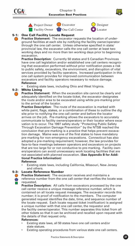
Practice Statements & Description 37
5-1: One Call Facility Locate Request Practice Statement: The excavator requests the location of under- ground facilities at each site by notifying the facility owner/operator through the one call center. Unless otherwise specified in state/ provincial law, the excavator calls the one call center at least two working days and no more than ten working days prior to beginning excavation. Practice Description: Currently 50 states and 5 Canadian Provinces have one call legislation and/or established one call centers recogniz- ing that excavation performed without prior notification poses a risk to public safety, excavators, the environment, and disruption of vital services provided by facility operators. Increased participation in this one call system provides for improved communication between excavators and facility operators necessary to reduce damage. Reference:
5-2: White Lining Practice Statement: When the excavation site cannot be clearly and adequately identified on the locate ticket, the excavator designates the route and/or area to be excavated using white pre-marking prior to the arrival of the locator. Practice Description: The route of the excavation is marked with white paint, flags, stakes, or a combination of these to outline the dig site prior to notifying the one call center and before the locator arrives on the job. Pre-marking allows the excavators to accurately communicate to facility owners/operators or their locator where exca- vation is to occur. The 1997 safety study “Protecting Public Safety Through Excavation Damage Prevention” by the NTSB reached the conclusion that pre-marking is a practice that helps prevent excava- tion damage. Maine was one of the first states to have mandatory pre-marking for non-emergency excavations. Connecticut has also adopted a pre-marking requirement; however, the law provides for face-to-face meetings between operators and excavators on projects that are too large for or not conductive to pre-marking. Facility own- ers/operators can avoid unnecessary work locating facilities that are not associated with planned excavation. (See Appendix B for Addi- tional Practice Information) Reference:
and others.5-3: Locate Reference Number Practice Statement: The excavator receives and maintains a reference number from the one call center that verifies the locate was requested. Practice Description: All calls from excavators processed by the one call center receive a unique message reference number, which is contained on all locate request messages. The excavator records this number; it is proof of notification to the members. The computer generated request identifies the date, time, and sequence number of the locate request. Each locate request ticket (notification) is assigned a unique number with that one call center, the requestor and the facility owner/operator. This number separates this ticket from all other tickets so that it can be archived and recalled upon request with the details of that request only. References:
Existing state laws, all 50 states have one call centers and/or state statues.
Chapter 5Excavation Best Practices
Best Practices Version 8.038
5-4: Pre-excavation Meeting Practice Statement: When practical, the excavator requests a meeting with the facility locator at the job site prior to the actual marking of facility locations. Such pre-job meetings are important for major, or unusual, excavations. Practice Description: The meeting will facilitate communications, coordinate the marking with actual excavation, and assure identifica- tion of high priority facilities. An on-site pre-excavation meeting between the excavator, the facility owners/operators and locators (where applicable) is recommended on major or large projects. This includes projects such as road, sewer, water, or other projects that cover a large area, progress from one area to the next, or that are located near critical or high priority facilities. Such facilities include, but are not limited to, high-pressure gas, high voltage electric, fiber optic communication, and major pipe or water lines. References:
Construction and W.F. Wilson & Sons, Inc.5-5: Facility Relocations Practice Statement: The excavator coordinates work which requires temporary or permanent interruption of a facility owner/operator’s service with the affected facility owner/operator in all cases. Practice Description: Any temporary or permanent interruption requires the active participation by the facility owner/operator and the excavator to ensure protection of facilities through a joint preplanning meeting or conference calls. One call centers note special contractor requests for a joint meeting on the ticket to the facility owner/operator to initiate the process. Reference:
5-6: Separate Locate Requests Practice Statement: Every excavator on the job has a separate one call reference number before excavating. Practice Description: Often, there are several excavators on a job site performing work. The construction schedule may dictate different types of work requiring excavation from different specialty contrac- tors simultaneously. In these situations it is imperative for each excavator to obtain a one call reference number before excavation to ensure that the specific areas have been appropriately marked by any affected underground facility owner/operator. Reference:
Illinois and others.5-7: One Call Access (24/7) Practice Statement: The excavator has access to a one call center 24 hours per day, 7 days a week. Practice Description: Utilities service the public needs 24x7 and thus should be protected the same amount of time. Certain conditions exist which requires excavators to work during off-hours (city/road congestion, off peak utility service hours). While most excavators are on the job site during regular work hours, the ability to call in future work locations after five p.m. allows more flexibility to schedule work, not to mention getting around peak hours of locate requests at the one call center. Reference: Existing states laws, including Texas, Idaho, Minnesota, Pennsylvania, and others. There are 25 participating states or one call centers with 24/7 access.5-8: Positive Response Practice Statement: The excavator is notified by the underground facility owner/operator of the tolerance zone of the underground facility by marking, flagging, or other acceptable methods at the work site, or is notified that a no conflict situation exists. This takes place after notification from the one call center to the underground facility owner/operator and within the time specified by state/provincial law.
Practice Statements & Description 39
Practice Description: If a facility owner/operator determines that the excavation or demolition is not near any of its existing underground facilities, it notifies the excavator that no conflict exists and that the excavation or demolition area is “clear.” This notification by the facility owner/operator to the excavator may be provided in any reasonable manner including, but not limited to: face-to-face communications; phone or phone message, facsimile or other electronic means; posting at the excavation or demolition area; or marking the excavation or demolition area. If an excavator has knowledge of the existence of an underground facility and has received an “all clear,” a prudent excavator will attempt to communicate that a conflict does indeed exist and the locator should make marking these facilities a priority before excavation begins. More communication between the excavator and the facility owner operator is a growing necessity as the area of excavation is getting more crowded everyday with new underground facilities. Positive response is a term used to describe the two types of action to be taken by a facility owner/operator after it has received notification of intent to excavate. The facility owner/operator is required to 1) mark its underground facilities with stakes, paint or flags or 2) notify the excavator that the facility owner/operator has no underground facilities in the area of excavation. This process allows the excavator to begin work on time or in a timely manner. When the excavator makes the request to the one call center, he/she is told which facility owners/operators will be notified. The excavator logs these facilities on his/her job sheet so that he/she can identify which facility owners operators have responded by marking and which ones have cleared the area. On the flip side, when a facility owner/operator does not respond by marking or clearing, this could signal that the facility owner/operator did not receive a locate notice. It could also indicate that the facility owner/operator data base used at the one call center is either corrupt or lacking the correct information to process the request at the location, which could result in calamity. Once the excavator has all of the information needed for the work area, he/she can then excavate with confidence with safety in mind for the work crew and the public at large. References:
others.
(Number of participating states or one calls: 31.)5-9: Facility Owner/Operator Failure To Respond Practice Statement: If the facility owner/operator fails to respond to the excavator’s timely request for a locate (e.g., within the time specified by state/provincial requirements) or if the facility owner/operator notifies the excavator that the underground facility cannot be marked within the time frame and a mutually agreeable date for marking cannot be arrived at, the excavator re-calls the one call center. However, this does not preclude the excavator from going on with the project. The excavator may proceed with excavation at the end of two working days, unless otherwise specified in state/provincial law, provided the excavator exercises due care in his endeavors. Practice Description: It is determined that the facility owner/ operator and the excavator will partner together to ensure facilities are marked in an acceptable time frame to allow for underground facility protection. Reference:
Michigan and others.5-10: Locate Verification Practice Statement: Prior to excavation, excavators verify they are at the correct location and verify locate markings and, to the best of their ability, check for unmarked facilities.
Best Practices Version 8.040
Practice Description: Upon arrival at the excavation site prior to beginning the excavation, verify that the dig site matches the one call request and is timely. Verify that all facilities have been marked, reviewing color codes if in doubt. Verify all service feeds from buildings and homes. Check for any visible signs of underground facilities, such as pedestals, risers, meters, and new trench lines. Check for any facilities that are not members of the one call center and contact someone to get them located. Use of a pre-excavation checklist is recommended by insurers and practiced by responsible excavating contractors. Reference:
and W.F. Wilson & Sons, Inc.5-11: Documentation Of Marks Practice Statement: An excavator uses dated pictures, videos, or sketches with distance from markings to fixed objects recorded, to document the actual placement of markings. Practice Description: In most situations when underground facilities are not properly marked, excavators have no way of knowing where underground utilities are located. If locate markings are adequately documented through the use of photographs, video tape, or sketches before excavation work begins, it will be easier to resolve disputes if an underground facility is damaged due to improper marking, failure to mark, or markings that have been moved, removed, or covered. It is important for excavators and locators to document the location of markings before excavation work begins. The primary purpose of this best practice is to avoid unnecessary litigation and expensive legal fees for all parties involved. Reference:
5-12: Work Site Review With Company Personnel Practice Statement: Prior to starting work, the excavator reviews the location of underground facilities with site personnel. Practice Description: Sharing information and safety issues during an on-site meeting between the excavator and his excavating crews will help to avoid confusion and needless damage to underground facilities. Reference:
A&L Underground, W.F. Wilson & Sons, Inc.5-13: One Call Reference Number At Site Practice Statement: The excavator’s designated competent person at each job site has the one call ticket number. Practice Description: This serves as a constant reminder that all excavators will be required to call the one call center to request a locate before they start excavation. If a representative for the facility owner/operator sees work being conducted and is unaware of the work being done, he/she can 1) stop and verify that the excavator does indeed have a valid ticket number or 2) check the third-party locator’s work. If an excavator is found working without a valid one call ticket number, he/she should be requested to stop work immediately and appropriate actions should be taken. Another positive aspect of this practice will be that it should speed up the notification process back to the one call center should the excavator find a facility incorrectly marked or not marked at all. Requiring personnel at the job site to have this number should minimize or eliminate calls to a supervisor, foreman, dispatcher, or other personnel to find the correct number if a problem is encountered. When multiple crews are working on the same project at separate locations, each crew should be responsible for having a designated competent person responsible for having this one call ticket number in their possession. References:
and W.F. Wilson & Sons, Inc.
Practice Statements & Description 41
Ameritech.5-14: Contact Names And Numbers Practice Statement: The excavator’s designated competent person at each job site has access to the names and phone numbers of all facility owner/operator contacts and the one call center. Practice Description: Situations arise on the job site that require immediate notification of the facility owner/operator, one call center or local emergency personnel. To avoid costly delays, the excavator ensures the designated job site personnel have all appropriate names and phone numbers. If telephone communication is unavailable, radio communication to the “home office” is available so that timely notification can be made. The “home office” also has immediate access to all appropriate names and telephone numbers. Reference:
5-15: Facility Avoidance Practice Statement: The excavator uses reasonable care to avoid damaging underground facilities. The excavator plans the excavation so as to avoid damage or minimize interference with the under- ground facilities in or near the work area. Practice Description: Foremost on any construction project is safety. Excavators using caution around underground facilities significantly contribute to safe excavation of existing facilities. Reference:
others.5-16: Federal And State Regulations Practice Statement: The excavator adheres to all applicable federal and state/provincial safety regulations, which includes training as it relates to the protection of underground facilities. Practice Description: Although most existing state/provincial damage prevention legislation does not include reference to federal and state/ provincial regulations, it is important to include reference to worker safety and training in the best practices. Excavators are required to comply with federal and state/provincial occupational safety and health requirements to protect employees from injury and illness. These regulations include reference to training each employee in how to recognize and avoid unsafe conditions and the regulations applicable to his/her work environment to control or eliminate any hazards or exposures to illness or injury. Therefore, the excavator’s crew, as part of its safety training, is informed of the best practices and regulations applicable to the protection of underground facilities. References:
5-17: Marking Preservation Practice Statement: The excavator protects and preserves the staking, marking, or other designations for underground facilities until no longer required for proper and safe excavation. The excava- tor stops excavating and notifies the one call center for re-marks if any facility mark is removed or no longer visible. Practice Description: During long complex projects, the marks for underground facilities may need to be in place far longer than the locating method is durable. Paint, staking and other marking tech- niques last only as long as the weather and other variables allow. When a mark is no longer visible, but work continues around the facility, the excavator requests a re-mark to ensure the protection of the facility. Reference:
5-18: Excavation Observer Practice Statement: The excavator has an observer to assist the equipment operator when operating excavation equipment around known underground facilities.
Best Practices Version 8.042
Practice Description: The observer is a worker who is watching the excavation activity to warn the equipment operator while excavating around a utility to prevent damaging that buried facility. This is common practice among excavators and large facility owners/ operators. Further, some state laws suggest the same, for example, Ohio law. References:
Southern Natural Gas, Bell South, and Columbia Gas.5-19: Excavation Tolerance Zone Practice Statement: The excavator observes a tolerance zone which is comprised of the width of the facility plus 18” on either side of the outside edge of the underground facility on a horizontal plane. This practice is not intended to preempt any existing state/provincial requirements that currently specify more than 18”. Practice Description: (See Practice Description for #20 below.) References:
Dakota and others.
Association (TIA/EIA), “Standard for Physical Location and Protection of Below-Ground Fiber Optic Cable Plant” (ANSI/TIA/EIA-590-A-1996).
Uniform Temporary Marking of Underground Facilities.”5-20: Excavation Within Tolerance Zone Practice Statement: When excavation is to take place within the specified tolerance zone, the excavator exercises such reasonable care as may be necessary for the protection of any underground facility in or near the excavation area. Methods to consider, based on certain climate or geographical conditions, include: hand digging when practical (pot holing), soft digging, vacuum excavation methods, pneumatic hand tools, other mechanical methods with the approval of the facility owner/operator, or other technical methods that may be developed. Hand digging and non-invasive methods are not required for pavement removal. Practice Description: Safe, prudent, non-evasive methods that manually determine a facility are considered “safe excavation practices” in a majority of state/provincial laws (38 states). A majority of states outline safe excavation practices to include hand digging or pot holing (16 states). Some states specifically allow for the use of power excavating equipment for the removal of pavement. Each state/province must take differing geologic conditions and weather related factors into consideration when recommending types of excavation within the tolerance zone. Reference:
Pennsylvania and others.5-21: Mis-marked Facilities Practice Statement: The excavator notifies the facility owner/ operator directly or through the one call center if an underground facility is not found where one has been marked or if an unmarked underground facility is found. Following this notification, the excavator may continue work if the excavation can be performed without damaging the facility, unless specified otherwise in state/provincial law. Practice Description: When an excavator finds an unmarked or inaccurately marked facility, excavation stops in the vicinity of the facility and notification takes place. If excavation continues, the excavator plans the excavation to avoid damage and interference with other facilities and protects facilities from damage. References:
Practice Statements & Description 43
Sons, Inc.5-22: Exposed Facility Protection Practice Statement: Excavators support and protect exposed underground facilities from damage. Practice Description: Protection of exposed underground facilities is as important as preventing damage to the facility when digging around the utility. Protecting exposed underground facilities helps to insure that the utility is not damaged and at the same time protect employees working in the vicinity of the exposed facility. Exposed facilities can shift, separate, or be damaged when they are no longer supported or protected by the soil around them. Excavators support or brace exposed facilities and protect them from moving or shifting which could result in damage to the facility. This can be accomplished in different ways, for example, by shoring the facility from below or by providing a timber support with hangers across the top of an excavation to insure that the facility does not move or bend. In addition, workers are instructed not to climb on, strike, or attempt to move exposed facilities which could damage protective coatings, bend conduit, separate pipe joints, damage cable insulation, damage fiber optics, or in some way affect the integrity of the facility. The Occupational Safety and Health Administration (OSHA) has also addressed this issue in Subpart P - Excavation Standard 29 CFR 1926.651(b)(4) which states: “While the excavation is open, under- ground installations shall be protected, supported, or removed as necessary to safeguard employees.” For example, an unsupported sewer main could shift causing the pipe joints to separate which could result in the trench where employees are working to flood, endangering the safety of employees. Reference:
Arizona, Virginia, Pennsylvania, New York and others.5-23: Locate Request Updates Practice Statement: The excavator calls the one call center to refresh the ticket when excavation continues past the life of the ticket (some- times, but not always, defined by state/provincial law). This recognizes that it is a best practice to define ticket life. If not currently defined in state/provincial law, ticket life would best be 10 working days but not to exceed 20 working days. Original locate request tickets are generated so that the minimum number of locate request updates are necessary for the duration of a project. Locate request updates are not generated after all the exca vation covered by a locate request is completed. Communication be- tween excavation project planners, field personnel, and clerical per sonnel is essential in accomplishing this task.22
Practice Description: Refreshing the ticket recognizes that markings are temporary and provides notification to facility owners/operators of ongoing excavation when a job is started but not completed as planned. Any excavation not begun during the life of the ticket is recalled to the one call center. Any excavation that covers a large area and will progress from one area to the next over a period of time is broken into segments when notifying the one call center in order to coordinate the marking with actual excavation. The possibility exists that new facilities have been installed in the area where the excava- tion is to be conducted after the original notification and marking. This practice also helps in situations where multiple excavators are working in the same area at essentially the same time. An example of when this can occur is when two facility owners, such as a cable television company and the telephone company, are planning to serve a new section of a subdivision. In their pre-planning process, they see a vacant space in the right-of-way to place their new facility. Each excavator (internal or external) calls the one call center for locates and each facility owner/operator comes and marks their respective facilities indicating that nothing exists. For one reason or
22 TR-2009-16: Amendment Approved by CGA Board on July 16, 2010.
Best Practices Version 8.044
23 TR-2009-16: Final Wording Approved by CGA Board on July 16, 2010.24 TR-2001-02A: Amendment Approved by CGA Board on November 30, 2001.25 TR-2001-02B: Amendment Approved by CGA Board on September 27, 2002.26 TR-2001-02B: Amendment Approved by CGA Board on September 27, 2002.
another, one of the excavators gets delayed and does not start construction as planned, and when returning to the job site to place the new facility, finds new lines have been installed in the previously vacant space. Many facility owners/operators do not perform their own locates and utilize the services of a contracted facility locator. These contracted facility locators may not be aware of work planned in the near future. By excavators refreshing the locate ticket, the contract locator has another opportunity to identify newly placed facilities. This practice also gives the facility owner/operator another chance to identify the location of their facilities and to avoid a possible damage and disruption of service should something have been marked incorrectly or missed on a previous locate. Excellent planning, generation, and updates of tickets will enhance safety and reduce the unnecessary use of locate resources.23
Reference:
Ohio, Wisconsin, Pennsylvania, and Texas. Existing state laws that specify 15 working days include Virginia and Tennessee. Progress Energy, Duke Energy & Arizona Blue Stake.5-24: Facility Damage Notification Practice Statement: An excavator discovering or causing damage to underground facilities notifies the facility owner/operator and the one call center. All breaks, leaks, nicks, dents, gouges, groves, or other damages to facility lines, conduits, coatings or cathodic protection will be reported. Practice Description: A majority of states require notification for damage or substantial weakening of an underground facility (27 states). The possibility of facility failure or endangerment of the surrounding population dramatically increases when a facility has been damaged. While the facility may not immediately fail, the underground facility owner/operator should have the opportunity to inspect the damage and make appropriate repairs. Reference:
others.5-25: Notification Of Emergency Personnel Practice Statement: If the damage results in the escape of any flammable, toxic, or corrosive gas or liquid or endangers life, health, or property, the excavator responsible immediately notifies 911 and the facility owner/operator.24 The excavator takes reasonable measures to protect themselves and those in immediate danger, the general public, property, and the environment until the facility owner operator or emergency responders have arrived and completed their assessment.25
Practice Description: This practice is already required by many of the states’ one call legislation. This practice minimizes the danger to life, health or property by notifying the proper authorities to handle the emergency situation. In these situations, local authorities are able to evacuate as appropriate and command substantial resources unavailable to the excavator or underground facility owner/operator. The excavator takes reasonable measures based on their knowledge, training, resources, experience and understanding of situation to protect themselves, people, property and the environment until help arrives. The excavator responsible remains on site to convey any pertinent information to responders that may help them to safely mitigate the situation.26
Reference:
Minnesota
Practice Statements & Description 45
5-26: Emergency Excavation Practice Statement: In the case of an emergency excavation, maintenance or repairs may be made immediately provided that the excavator notifies the one call center and facility owner/operator as soon as reasonably possible. This includes situations that involve danger to life, health or property, or that require immediate correction in order to continue the operation of or to assure the continuity of public utility service or public transportation. Practice Description: This allows excavation to begin immediately to restore service or stop a hazardous situation from getting worse in the case of gas or pipeline leak, telephone cable cut, or other facility damage. Reference:
and others. (Number of participating states or one calls = 49.)5-27: Backfilling Practice Statement: The excavator protects all facilities from damage when backfilling an excavation. Trash, debris, coiled wire, or other material that could damage existing facilities or interfere with the accuracy of future locates are not to be buried in the excavation. Practice Description: Extra caution must be taken to remove large rocks, sharp objects, and large chunks of hard packed clay or dirt. No trash or pieces of abandoned lines are backfilled into the trench. This will avoid any inadvertent damage to the facility during the backfill process. References:
5-28: As-built Documentation Practice Statement: Contractors installing underground facilities notify the facility owner/operator if the actual placement is different from expected placement. Practice Description: In order for a facility owner/operator to main- tain accurate records of the location of their facilities, it is critical that the contractor installing the new facility be required to notify the facility owner/operator of deviations to the planned installation. Some facility owners/operators do not require a full time inspector and use a sampling process to insure the new facilities are being installed correctly and in adherence to the specifications. When this occurs, it becomes much more critical for the contractor to notify the facility owner/operator of changes. For example, it is common for the contractor to make adjustments in the location of the new facilities when rocks or other underground obstructions are encountered or the location of the new facility conflicts with another existing under- ground facility. This change in plan can be both changes in horizontal or vertical distances from the specified plans. The facility owner/operator should establish standards that require notification if a deviation is beyond specified tolerances, such as changes in depth of 6 inches or more and lateral measurement changes of greater than 1 foot. Once these changes to the expected location are communicated to the facility owner/operator, it is their responsibility to take appropriate action to update their records so that an accurate locate can be conducted in the future. Reference:
Ameritech, Sprint, Columbia Gas and others.5-29: Trenchless Excavation27
Practice Statement: All stakeholders adhere to all Best Practices and the following general guidelines prior to, during and after any trenchless excavation (as applicable): Practice Description:
the entrance pit, trenchless excavation path, and the exit pit by notifying the facility owner/operator through the one call center.
27 TR-2002-03: Amendment Approved by CGA Board on September 16, 2005.
Best Practices Version 8.046
28 TR-2005-02: Amendment Approved by CGA Board on September 8, 2006. 29 TR-2007-06: Amendment Approved by CGA Board on August 8, 2008.30 TR-2009-09: Amendment Approved by CGA Board on September 10, 2010.
walking the trenchless excavation path prior to commencing work and has a good understanding of the job.
path and minimum clearances established by the project owner and design engineer by tracking and recording the path of the trenchless excavation until complete. Means of tracking trenchless excavations include: electronic locating / guidance devices, pipe lasers, water levels, visual inspection, etc.
potholed due to local conditions the facility owner and the excavator meet to discuss how to safely proceed with the excavation.
condition, unknown substructure or other hidden hazard is encountered. Proceed safely only after positive identification has been made. (Additional Information: Refer to practices 2-13 & 4-19) References: See Appendix D5-30: Emergency Coordination with Adjacent Facilities28
Practice Statement: Emergency response planning includes coordination with emergency responders and other above and/or underground infrastructure facility owner/operators identified by the Incident Commander through the Incident Command System/Unified Command (ICS/UC) during an emergency. Practice Description: During emergency situations there are many stakeholders involved: excavators; locators; owner/operators; first responders; one call centers; and the general public. Any actions taken by one stakeholder could adversely affect other stakeholders. Accordingly, emergency planning and response should be coordinated. References:
Gas Emergency Procedure Manual5-31: No Charge for Providing Underground Facility Locations29
Statement: Upon notification by one call centers, locations of under-ground facilities are provided by operators at no cost to excavators.
Rationale/Description: It is the basic underpinning of the call before you dig process that persons involved in excavation activities receive facility locates at no charge when they contact their local one call center to give notice of intent to excavate. This service is critical to maintaining the communication between operators and excavators. Call before you dig education and marketing campaigns, such as 811, and those promoted by one call centers and associated industries, advise persons involved in excavation activities including the public, homeowners and professional excavators, that the service is pro-vided by facility operators at no charge to the person providing the notice of intent to excavate.
References: MN State Statutes, Alberta Pipeline5-32: Vacuum Excavation30
Practice Statement: Vacuum excavation, when used appropriately, is an efficient, safe and effective alternative to hand digging within the designated underground facility tolerance zone. Use of equip- ment must also follow State/Provincial Laws and/or Local Ordinances. Practice Description: The safe exposure of underground facilities within the tolerance zone is essential to damage prevention. Site conditions may make the use of hand tools to expose underground facilities difficult or even impractical. Vacuum excavation is often an appropriate alternative. Locates must be obtained prior to the commencement of work (Best Practice 5-1). Many underground facility owners/operators have specific criteria for safe excavation/exposure practices around their facilities. Some
Practice Statements & Description 47
underground facility owners/operators accept vacuum excavation as equivalent to hand excavation for exposing their facilities and others have restrictions on its use. Vacuum excavation is an appropriate method of excavating safely around underground facilities provided that: the equipment has been specifically designed and built for this purpose; the equipment is operated by a worker trained and experienced in its operation; the equipment is operated in accordance with practices that provide appropriate levels of worker and public safety and prevent damage to buried facilities; and use of the equipment complies with state/provincial laws and/or local ordinances.

Best Practices Version 8.048
For additional information on the Common Ground Alliance or to learn how to become a member, visit the CGA web site at
www.commongroundalliance.com
Practice Statements & Description 49
A decision was made by the Mapping Team to look at mapping practices from the viewpoint of the different areas represented by the Team mem-bers. Therefore, the best practices for mapping are listed in five distinct areas: One Call Center, Locator, Excavator, Facility Owner/Operator, and Project Owner. By consensus of the Mapping Task Team, all of the findings listed below are best practices.
One Call Center A one call center uses an electronic mapping database system that includes the following:6-1: The land base should be accurate. Accuracy - The land base is the most precise geographical information available to the one call center. The one call centers in the following states follow this practice: Arizona, Minnesota, North Carolina, Texas, and Wisconsin.6-2: The land base and database uses latitude/longitude. Latitude/Longitude (Lat/Long) - The land base and database are able to produce Lat/Long information based upon street address, street/road name, intersection, milepost marker, etc. It is also possible to determine the street address, street/road name, intersec- tion or milepost based upon Lat/Long information. The translation of Lat/Long information is automatic. A map point (i.e., a rural area not in the immediate vicinity of a road or known map landmark) can be identified by Lat/Long information. The one call centers in the following states follow this practice: Ohio, South Dakota, New Jersey, Missouri, and Tennessee.6-3: The land base is up-to-date. The land base is kept up-to-date, including a process that periodically adds new street information, name changes, aliases, and municipal boundaries. The one call centers in the following states follow this practice: Arizona, Ohio, and New Jersey.6-4: The database is updated by information from facility owners/operators. The database is promptly updated as information is provided or becomes available from the facility owner/operator. The system is able to accept information in standard file format with minimal human intervention. The one call centers in the following states follow this practice: Arizona, North Carolina, Ohio, New Jersey, and Wisconsin. 6-5: The electronic mapping system can produce a ticket for the smallest practical geographical area. Location Area - The electronic mapping system is able to produce a ticket for the smallest practical geographical area. The one call centers in the following states follow this practice: Arizona, Tennessee, Minnesota, Oregon, and Wisconsin.6-6: The land base is available to the public. Availability - The land base is available to the public for the identification of the excavation area. The land base and database are available to the one call center membership for the update of member database information. The one call centers in the following states follow this practice: North Carolina, Ohio, and South Dakota.
Locator Locators use maps to assist in finding the excavation site and to assist in determining the general location of the buried facility.
6-7: Locators are trained in map reading and symbology. Locators are trained in map reading and symbology to assist in
Chapter 6Mapping Best Practices
Best Practices Version 8.050
determining the location of the buried facility. The following association trains its members to carry out this practice: NULCA.6-8: The locator provides precise facility location to the facility owner/operator when there is a discrepancy. The locator provides to the facility owner/operator the most precise facility location information obtained from a locate when there is a discrepancy. The following state carries out this practice: Arizona Blue Stake law.6-9: The locator supplies feedback to the one call center. The locator provides feedback to the one call center on land base mapping and location discrepancies. The following states carry out this practice: Ohio, Tennessee, and North Carolina.
Excavator 6-10: The excavator provides accurate location information to the one call center. The excavator takes responsibility for giving accurate location information to the one call center. This information includes street address, street intersection, legal description, or other acceptable one call format and latitude/longitude if feasible.6-11: The excavator provides basic attributes to the one call center. The excavator provides a starting point and ending point, and on which side of the property (North, South, East, West, front, back, rear, sides, etc.) or street the excavation area is located. If the excavator cannot meet the above criteria, the excavator directly coordinates with the one call center to establish the excavation area. References:
Facility Owner/Operator 6-12: The facility owner/operator provides mapping data to the one call center. The facility owner/operator provides the one call center with data that will allow proper notification of excavation activities near the facility owner/operators’ infrastructure. Facility owners/operators in all mandatory one call states follow this practice.6-13: The facility owner/operator provides mapping data access. The facility owner/operator provides access to a mapping system that can be utilized by both the locator and the facility owner/operator. The following facility owners/operators follow this practice: Atlanta Gas Light, Sprint Long Distance, AT&T, Questar Regulated Services.6-14: Mapping standards are adhered to. The facility owner/operator requires the designer to adhere to the facility owner/operator’s mapping standards. The following facility owners/operators follow this practice: AT&T, Sprint Long Distance.6-15: Consistent, current information is provided to the one call center. The facility owner/operator provides consistent, current information to the one call center for the proper receipt of ticket notification. Basic information should include latitude and longitude and should be tied to a physical attribute where available, such as milepost marker. The following facility owner/operator follows this practice: Sprint Long Distance.6-16: Detailed mapping information is collected. The facility owner/operator captures the following information to ensure project safety in the plan, design, construction, documenta- tion, location, and maintenance of their longitudinal utility. 1. Any new construction into the electronic mapping database at the time of installation 2. The location of abandoned or sold facilities is retained in the database. 3. The electronic mapping database includes the following detailed information: a. Engineering stationing and milepost/marker post location, with latitude and longitude. Common mapping coordinate
Practice Statements & Description 51
systems that allow conversion to latitude and longitude are used. b. Alignment of the utility with engineering stationing at each running line change or PI (point of inflection) including signs and markers. c. Bridges, culverts and rivers. d. All road crossings, overhead viaducts and underpasses, including name of the street (public or private) and mile marker/marker post designation. e. Small scale maps showing the overall utility route. f. Physical characteristics and attributes of the system such as: pedestal, pole, transformer, meter numbers, anode bed, size, material, product and pressure. g. The number of utility lines or conduits owned by the facility owner/operator in a corridor or the size of the duct package bank. This is universally a general practice of major pipe line and long distance telecommunication operators and railroads. 4. When practical, use digital imagery as a method of identifying facility locations in relation to the surrounding environment.31
Project Owner 6-17: The project owner provides accurate information. The project owner provides the excavator with accurate location information on the proposed excavation area using mapping information utilized by the one call center. This information includes: a street address, street intersection, legal description, or other acceptable one call format such as ortho-photography and latitude/ longitude if feasible.32
6-18: The project owner determines basic coordinates. The project owner determines a starting point, ending point and on which side of the property (North, South, East, West, front, back, rear, sides, etc.) or street the excavation area is located. Reference:
These are general practices of the State DOTs on Highway projects.
references listed in each best practice are not all inclusive.
Emerging TechnologiesTechnology is rapidly changing. Many of the best practices identified in this chapter could be obsolete in the near future. Although the following technologies are now used in other applications, their use is not widespread in the damage prevention field.
GIS allows the integration of digital maps with other databases to view the relationship of physical features, conducts relational queries, and obtains additional information on a particular feature. The GIS infrastructure or base will support all of the advanced technologies of GPS, Ortho and Satel-lite Images.
Combining Orthographic and Satellite images with an overlay of a line map, street names, addresses and GPS coordinates of utility lines will allow one call centers, excavators, locators, facility owners/operators, and project owners to view the accurate and relative location of utility lines.
Advanced use of these technologies in combination with advances to locat-ing technologies is expected to reduce damage to underground facilities.31 TR-2008-03: Amendment Approved by CGA Board on July 16, 2010.32 TR-2008-01: Amendment Approved by CGA Board on May 15, 2009.
Best Practices Version 8.052
For additional information on the Common Ground Alliance or to learn how to become a member, visit the CGA web site at
www.commongroundalliance.com
Practice Statements & Description 53
7-1: Public And Enforcement Education A. Public Education Practice Statement: Public education programs are used to promote compliance. Practice Description: A single entity is charged to promote comprehensive and appropriate programs to educate all stake holders about the existence and content of the damage preven- tion laws and regulations. This is not meant to discourage individual stakeholders from providing educational programs. Reference: New York: “Each one call notification system shall perform the following duties: ...(b) Conduct a continuing program to: (1) Inform excavators of the one call notification system’s existence and purpose and their responsibility to notify the one- call notification system of proposed excavation and demolition and to protect underground facilities. (2) Inform operators of the responsibility to participate in the one call notification system, to respond to a notice relating to a proposed excavation and demolition and to designate and mark facilities according to the provisions of this Part.” New York Code, 16 NYCRR Part 753, § 753-5.3(b)(1)-(2). B. Enforcement Education Practice Statement: Mandatory education is considered as an alternative or supplement to penalties for offenders of the damage prevention laws and regulations. Practice Description: Once a violation of the damage prevention laws or regulations has occurred, mandatory education is an effective alternative or supplement to civil penalties. Mandatory education as an enforcement tool promotes compliance with damage prevention laws and regulations. References: following may be followed: 1. First Time Offenders: A. May be given a warning letter and Item C below...C. Given the opportunity to attend Blue Stake Training Course provided by the Arizona Corporation Commission’s Pipeline Safety Section.” Arizona Corporation Commission policy, “Notice of Violation,” § 1(A) and (C).
comply with RSA 374:51-54 shall be required on first offense to go through either a Digsafe training program or be subject to a civil penalty...” New Hampshire Code, RSA 374, § 374:55(VIII).7-2: Incentives Practice Statement: Damage prevention programs include incentives to promote compliance with laws and regulations. Practice Description: Incentives can include, but are not limited to, ease of access to one call center, membership and participation considerations, representation on one call boards, reasonable enforcement of regulations, safety and liability protection, access to alternative dispute resolution (ADR), and public education. Incentive - Membership: Membership facilitates communication between an excavator and facility owner/operator, which helps prevent damage to underground facilities.
The following icons apply to all practices in this chapter:
Chapter 7Compliance Best Practices
Best Practices Version 8.054
References:
locates the underground facility, pursuant to this article, the owner or operator becomes liable for resulting damages, costs and expenses to the injured party.” Arizona Code, Article 6.3, § 40- 360.27(C).
underground facility was caused by the sole negligence of the operator or the operator failed to comply with section 216.04, subdivision 3.” Minnesota Code, Chapter 216D.06, Subd. 2(b).
in violation of state law are not permitted to recover damages for injury to their property: “If a facility owner fails to become a member of a One Call System in violation of this act and a line or lines of such nonmember facility owner are damaged by a contractor by reason of the contractor’s failure to notify the facility owner because the facility was not a member of a One Call System serving the location where the damage occurred, such facility owner shall have no right of recovery from the contractor of any costs associated with the damage to its lines. The right herein granted shall not be in limitation of any other rights of the contractor.” Pennsylvania Code, 73 P.S. § 176 et. seq., Section 2(9). Incentive - Membership Accommodations: To avoid cost being a barrier to membership, several states have made membership accommodations for smaller municipals and authorities. References:
limited basis participation membership option, which may be made available to all members, but which must be made available for any member serving less than one thousand customers or any member irrigation or electrical district. A facility owner who elects limited basis participation membership will provide to the one call center the location of its underground facilities by identifying the incorporated cities and towns, or for unincorporated county areas, by identifying the townships, in which it has facilities. The service level provided to the limited basis participation members by the one call notification center is limited to providing excavators with names and telephone numbers the excavator should contact to obtain facilities location. Each one call center shall establish fair and reasonable fees for limited basis participation members, based on customer count, areas occupied or miles of underground facilities.” Arizona Code, Article 6.3, § 40-360.32. *Note, Arizona’s system somewhat defeats the purpose of “one call”, but is successful because the Arizona Blue Stake, the one call center, goes the extra mile to assist the excavator in contacting the small facility owners, many of which do not have a manned telephone line.
locate-required policy, which credits the facility operator those charges for “not-involved” tickets. It results in cost savings to the facility owners/operators because one call center membership rates are based on the number of tickets received by the facility owners/operators.
The following icons apply to all practices in this chapter:
Practice Statements & Description 55
apportioned equitably among the members of the system, with the exception of municipalities and authorities that operate underground facilities and any operator of underground facilities that provides water service to less than four thousand customers. In apportioning such costs, the system shall take into account the number of customers, extent of underground facilities and frequency of use.” New York General Business Law Article 36, § 761.
shared, in an equitable manner for services received, by facility owner members as determined by a One Call System’s board of directors. Political subdivisions with a population of less than two thousand persons or municipal authorities having an aggregate population in the area served by the municipal authority of less than five thousand persons shall be exempt from payment of any service fee.” Pennsylvania Code, 73 P.S. § 176 et. seq., Section 2(8). Incentive - One Call Center Board of Directors: Boards are composed of representatives of all stakeholders. Representation of all stake holders in the governance of the one call center (although not necessarily in the administration of the one call center) assures that the viewpoint of all stakeholders will be considered in the policies and programs of the one call center. References:
board of directors of up to 20 members, one of whom is the director of the office of pipeline safety. The other board members must represent and be elected by operators, excavators, and other persons eligible to participate in the center...” Minnesota Code, Chapter 216D.03, Subd. 2(a).
of directors, to be chosen by the facility owners. No less than twenty percent of the seats shall be held by municipalities or municipal authorities. The board shall include the following: (1) The Chairman of the Pennsylvania Public Utility Commission or his designee. (2) The Director of the Pennsylvania Emergency Management Agency or his designee. (3) The Secretary of Labor and Industry or his designee. (4) The Secretary of Transportation or his designee. (5) A contractor or industry representative. (6) A designer or industry representative.” Pennsylvania Code, 73 P.S. § 176 et. seq., Section 7.1(b). Incentive - Safety and Liability Protection: Compliance with one call center requirements promotes worker safety, public safety and reduces exposure to liability. References:
apply to an excavator who damages an underground facility due to the failure of the operator to comply with any of the provisions of this article nor shall in such instance the excavator be liable for repairs as prescribed in subdivision four of this section.” New York Code, 16 NYCRR Part 753, § 765(b).
this act and who was not otherwise negligent shall not be subject to liability or incur any obligation to facility owners, operators, owners or other persons who sustain injury to person or property as a result of the excavation or demolition planning work of the designer.” Pennsylvania Code, 73 P.S. § 176 et. seq., Section 3(7).
The following icons apply to all practices in this chapter:
Best Practices Version 8.056
Incentive - Reasonable Enforcement of Regulations: Reasonable enforcement of regulations refers to actions by enforcement authority officials and enforcement processes, both of which aim to fairly arrive at rational outcomes, such as education and penalties that correspond to the gravity of the violation, without imposing unnecessarily high transaction costs on any participant, including the enforcement authority. Reference: considered when addressing a violation, repeat offenders of the one call law can attain first-time offender status if they demon- strate compliance for a solid year. “Any person, contractor, excavator or company found by the Department to have violated any provision of the Dig Safe law or regulation adopted by the Department thereunder shall be subject to a civil penalty not to exceed $500 for the first offense and not less than $1,000 nor more than $5,000 for any subsequent offense within a 12 month period after the Department issues a remedial order or executes a consent order for the first offense. Any excavator whose subsequent violation occurs after 12 consecutive months of no violations shall be subject to a civil penalty of $500.” Massachusetts Regulation, 220 C.M.R. §99.12(1).7-3: Penalties Practice Statement: Compliance programs include penalties for violations of the damage prevention laws or regulations. Practice Description: Within the context of one call statutes, there exists specific provisions for penalties for failure to comply with the damage prevention laws and regulations. Performance and penalty incentives are equitably administered among stakeholders subject to one call provisions. A penalty system includes education as an alternative or supplement to civil or other penalties. Reference:
comply with RSA 374:51-54 shall be required on first offense to go through either a ‘Digsafe’ training program or be subject to a civil penalty...” New Hampshire Code, RSA 374, § 374:55(VIII). A penalty system also uses a tiered structure to distinguish violations by the level of severity or repeat offenses (e.g., warning letters, mandatory education, civil penalty amounts). References:
following may be followed: 1. First Time Offenders: A. May be given a warning and Item C below or B. May be fined $250 per violation and C. Given the opportunity to attend a Blue Stake Training Course provided by the Arizona Corporation Commission’s Pipeline Safety Section. Note: The investigator may use the N.O.V. as a warning, if they feel a warning would suffice. 2. Second Offense: A. May be fined $250 per violation and B. Given the opportunity to attend a Blue Stake Training Course provided by the Arizona Corporation Commission Pipeline Safety Section. 3. Repeat Offenders: A. Third Time: May be fined $500 per violation. B. Four or More Times: Could be fined up to $2000 per violation. Flagrancy or magnitude of offense could cause pipeline safety to deviate from this policy. Any deviation to the above-state police will jointly be determined by the Chief of Pipeline Safety and the Investigator.” Arizona Corporation Commission policy, “Notice of Violation,” section 1-3.
The following icons apply to all practices in this chapter:
Practice Statements & Description 57
violation(s) of a provision of Part 753 has occurred or is continuing, the Department may issue a warning letter notifying the Respondent of the probable violation and advising him or her to correct it, if it is correctable, and to comply henceforth, or be subject to enforcement actions under this Part.” NY Public Service Commission policy (proposed code § 753-6.3). A penalty system also establishes mitigating and aggravating factors for determining the penalty for a violation by statute or regulation. References:
the Department shall consider the nature, circumstances and gravity of the violation; the degree of the respondent’s culpability; the respondent’s history of prior offenses; and the respondent’s level of cooperation with the requirements of this regulation.” Massachusetts Regulation, 220 C.M.R. §99.12(2).
shall consider the following factors: A. the nature, circumstances, and gravity of the violation; B. the degree of the person’s culpability; C. the person’s history of previous offenses; D. the person’s ability to pay; E. good faith on the part of the person in attempting to remedy the cause of the violation; F. the effect of the penalty on the person’s ability to continue business; and G. past reports of damage to an underground facility by a person.” Minnesota Rules, 7560.0800, Subpart 3.
factors shall be considered: (1) Severity of the consequences resulting from the violation: the more severe the consequences, the higher the civil penalty; (2) Mitigating circumstances: i.e., how quickly actions were taken to rectify the situation, how much control the company had over the situation, and other circumstance which would tend to less fault; and (3) Prior violations of Puc 800.” New Hampshire Regulation, Chapter Puc 800, § Puc 805.06(b)(1)-(3).
penalty after consideration of the nature, circumstances and gravity of the violation, history of prior violations, effect on public health, safety or welfare, and such other matters as may be required and shall send a copy of its determination to the excavator, operator, commissioner of labor and attorney general.” New York Public Service Law, § 119-b(8).
included in a settlement, the nature, circumstances and gravity of the violation; the degree of the Respondent’s culpability; the Respondent’s history of prior offenses; and such other factors as may be appropriate shall be considered.” Virginia “Rules for Enforcement of the Underground Utility Damage Prevention Act,” § 6. A penalty system does not allow any violator or class of violators to be shielded from the consequences of a violation (i.e., all stake- holders should be accountable). Reference:
comply with RSA 374:51-54 shall be required on first offense to go through either a ‘Digsafe’ training program or be subject to a civil penalty...” New Hampshire Code, RSA 374, § 374:55(VIII).
The following icons apply to all practices in this chapter:
Best Practices Version 8.058
7-4: Damage Recovery Practice Statement: State damage prevention laws and regulations recognize the right to recover damages and costs resulting from noncompliance. A. Right of Recovery Practice Description: The statute recognizes an injured party’s right to recovery when damages and/or costs are incurred as the direct result of an entity’s failure to comply with the one call laws and regulations. For example, Arizona endorses an injured party’s right to recover damages when the other party has failed to comply with the one call law. References: a result of failing to obtain information as to its location, failing to take measures for protection of the facilities or failing to excavate in a careful and prudent manner as required by this article, the person is liable to the owner of the underground facility for the total cost of the repair of the facility.” Arizona Code, Article 6.3, § 40-360.26(A).
locates the underground facility, pursuant to this article, the owner or operator becomes liable for resulting damages, costs and expenses to the injured party.” Arizona Code, Article 6.3, § 40-360.28(C). B. Alternative Dispute Resolution Practice Description: Avenues for settlement of disputes include alternative dispute resolution. Minnesota endorses ADR through the state court system, New Jersey endorses ADR in construction contract documents, and the federal government endorses ADR through the federal courts. References: alternative dispute resolution program for the resolution of civil cases filed with the courts. The Supreme Court shall adopt rules governing practice, procedure, and jurisdiction for alternative dispute resolution programs established under this section. Except for matters involving family law the rules shall require the use of nonbinding alternative dispute resolution processes in all civil cases, except for good cause shown by the presiding judge, and must provide an equitable means for the payment of fees and expenses for the use of alternative dispute resolution processes.” Minnesota Code, Chapter Title: District Courts, § 484.76.
accordance with the provisions of P.L. 1971, c. 198 (C.40A:11-1 et seq.) after the effective date of P.L. 1997, c.371 (C.40A:11-50) shall provide that disputes arising under the contract shall be submitted to a process of resolution pursuant to alternative dispute resolution practices, such as mediation, binding arbitration or non-binding arbitration pursuant to industry standards, prior to being submitted to a court for adjudication. Nothing in this section shall prevent the contracting unit from seeking injunctive or declaratory relief in court at any time. The alternative dispute resolution practices required by this section shall not apply to disputes concerning the bid solicitation or award process, or to the formation of contracts or subcontracts to be entered into pursuant to P.L. 1971, c. 198 (C.40A:11-1 et seq.).” New Jersey Code, Title 40A, § 40A-11-50.
The following icons apply to all practices in this chapter:
Practice Statements & Description 59
when supported by the bench and bar, and utilizing properly trained neutrals in a program adequately administered by the court, has the potential to provide a variety of benefits, including greater satisfaction of the parties, innovative methods of resolving disputes, and greater efficiency in achieving settlements; (2) certain forms of alternative dispute resolution, including mediation, early neutral evaluation, minitrials, and voluntary arbitration, may have potential to reduce the large backlog of cases now pending in some federal courts throughout the United States, thereby allowing the courts to process their remaining cases more efficiently; and (3) the continued growth of Federal appellate court-annexed mediation programs suggests that this form of alternative dispute resolution can be equally effective in resolving disputes in the federal trial courts; therefore, the district courts should consider including mediation in their local alternative dispute resolution programs...Each United States district court shall authorize, by local rule adopted under section 2071(b) 2071(a), the use of alternative dispute resolution processes in all civil actions, including adversary proceedings in bankruptcy, in accordance with this chapter, except that the use of arbitration may be authorized only as provided in section 654 [(1) the action is based on an alleged violation of a right secured by the Constitution of the United States; (2) jurisdiction is based in whole or in part on section 1343 of this title; or (3) the relief sought consists of money damages in an amount greater than $150,000.].” Alternative Dispute Resolution Act of 1998, enacted October 1998.7-5: Enforcement A. Authority Practice Statement: An authority is specified through state statutes and given the resources to enforce the law. Practice Description: The enforcement authority in each state has the resources to enforce the laws and regulations. Experience has demonstrated that enforcement of the one call laws and regulations that did not identify a specific authority other than the attorney general has not been effective. Characteristics of such an authority include:
line item in the state budget, excluding fines as a source of income for the authority;
enforcement processes;
timely manner;
notice of probable violation;
considerations. References:
Commission is funded by the Commission budget. “Any penalties received by the state shall be deposited in the general fund.” Arizona Code, Article 6.3, § 40-360.28.
violation of M.G.L. c. 82 s. 40 to the Department. All such reports shall be in a form deemed appropriate and necessary by the Department.” Massachusetts Regulation, 220 C.M.R. §99.01(1).
The following icons apply to all practices in this chapter:
Best Practices Version 8.060
cations and Energy investigates all complaints received from excavators and facility owners/operators and conducts random field investigations. The Department then issues a Notice of Probable Violation if, based on the investigation, it has reason to believe that a violation has occurred or is occurring. “The Department may begin a proceeding by issuing a notice of probable violation (“NOPV”) if the Department has reason to believe that a violation of the M.G.L. c. 82, § 40, has occurred or is occurring...The NOPV shall state the factual basis for the allegation of a violation...” Massachusetts Regulation, 220 C.M.R. §99.07(1).
when the office has good cause to believe a violation of Minnesota Statutes, sections 216D.01 to 216.D.09 or this chapter has occurred...A notice of violation must include: A. a statement of the statute or rule allegedly violated by the person and a description of the evidence on which the allegation is based.” Minnesota Rules, 7560.04000, Subp.1 - Subp. 2(A).
of Violation; 7560.0500 Response Options; 7560.0600, Director Review;7560.0800 Civil Penalties; Subp. 3, Assessment considerations.
Probable violation] the respondent shall either: (1) Submit in writing, within 30 days, evidence refuting the probable violation referenced in the NOPV; or (2) Request in writing within 30 days, an informal conference with commission staff to examine the basis of the violation, at which time the respondent may be represented by an attorney or other person; or (3) Waive procedural schedule by signing a consent agreement.” New Hampshire Regulation, Chapter Puc 800, § Puc 805.02.
Puc 800, sections Puc 805.01, “Notice of Probable Violation”; Puc 805.02, Alternative Responses to Notice of Probable Violation; Puc 805.03, Notice of Violation; Puc 805.04, Response to Notice of Violation; Puc 805.05 Commission Action; Puc 805.06, Civil Penalties.
statute to include “representatives of the following entities: Commission staff, utility operator, notification center, excavator, municipality, Virginia Department of Transportation, Board of Contractors and underground line locator,” meets one day annually (in addition the monthly hearings) for “issue day,” a day to discuss issues and make recommendations to the State Corporation Commission (SCC) administrative 3-judge panel on issues related to damage prevention. Subteams of the Advisory Committee are also formed to develop recommendations. “The purpose of the Committee is to ...make recommendations with regard to Public Education and Awareness Programs that further public safety by the reduction of damage to the underground utility facilities in the Commonwealth and to monitor, analyze, influence, propose, support or oppose programs or regulations that directly affect damage to underground facilities serving the citizens of the Commonwealth.” Bylaws of the Advisory Committee, Article II.
Commission Staff (“Staff”) shall conduct an investigation to examine all the relevant facts regarding the reported probable violation. The investigation may include, among other things,
The following icons apply to all practices in this chapter:
Practice Statements & Description 61
records verification, informal meetings, teleconferences and photo-documentation. Upon completion of the investigation, the Staff shall review its findings and recommendations with the
of the Act.” Virginia “Rules for Enforcement of the Underground Damage Prevention Act,” § 3. B. Structured Review Process Practices Statement: A structured review process is used to impartially adjudicate alleged violations. Practice Description: Two types of review processes currently used are outlined below. These type of processes differ in terms of 1) who receives reports of alleged violations, 2) who investigates the reports, 3) possible outcomes of the investigation, 4) who conducts 1st tier (informal) hearings, 5) possible outcomes of 1st tier hearings, and 6) appeal rights following a 2nd tier (formal) hearing. It is important that review processes are constructed to avoid abuses of authority and prevent any individual, industry, stakeholder or agency from exercising undue power or influence over the process. Type 1: Traditional Enforcement Authority - This system is currently used in Arizona, Connecticut, Massachusetts, Minnesota, New Hampshire, New Jersey, New York and Pennsylvania. Reports of alleged violations are sent to the State Agency. A state investigator investigates the reports. If the investigator decides not to issue a NOPV (Notice of Probable Violation), the matter is concluded. If not, the NOPV is issued, and the investigator conducts an informal hearing or review. If the investigator determines that no violation was committed the matter is concluded. If the investigator determines that a violation was committed, the NOV (Notice of Violation) is issued. If the alleged violator does not contest the NOV, the alleged violation is bound by the facts, findings, orders and penalties set forth in the NOV. If the alleged violator so requests, the State Agency conducts a formal hearing. The alleged violator may appeal the decision reached in the formal hearing to the state court system. Type 2: Advisory Committee (made up of stakeholders) partnered with State Agency - This system is currently used in Virginia. Reports of alleged violations are sent to the State Enforcement Agency. The State Agency investigates the alleged violations and reports to an advisory committee. The Committee is made up of stakeholders representing the following statutorily mandated fields: excavators, facility owners/operators, notification centers, contract locators, local governments, State Department of Transportation, the Board of Contractors, and the State Enforcement Agency. If the advisory committee decides not to issue a NOPV (Notice of Probable Violation), the matter is concluded, possibly with a “letter of concern” containing one call information. If the advisory committee decides to issue an NOPV, it is issued by the State Agency. If the alleged violator does not request a hearing, the alleged violator is bound by the enforcement action set forth in the NOPV. If the alleged violator so requests, an informal hearing is held by the advisory committee. If the advisory committee decides that no violation was committed, the matter is concluded, subject to the right of the State Agency to contest that decision in an administrative proceeding conducted by the agency. If not, the NOV is issued. If the alleged violator then settles the matter with the advisory committee, the settlement is subject to approval by the State Agency in an administrative proceeding. If there is no settlement, the State Agency conducts a formal administrative hearing. The alleged violator may appeal the decision reached in the formal hearing to the state court system.
The following icons apply to all practices in this chapter:

Best Practices Version 8.062
For additional information on the Common Ground Alliance or to learn how to become a member, visit the CGA web site at
www.commongroundalliance.com
Practice Statements & Description 63
8-1: Use Of A Marketing Plan Practice Statement: An effective damage prevention education program includes a comprehensive, strategic marketing/advertising plan. Practice Description: A comprehensive, strategic marketing/advertis- ing plan enables better implementation, control, and continuity of advertising/public relations programs and ensures the most effective and efficient use of limited resources. These plans focus on setting realistic goals and allocating sufficient resources required to achieve those goals within a specified time frame. The marketing plan is a set of action steps based on a comprehensive situation analysis that clearly states:
allocated to achieving each goal. References:
Plan.
Damage Prevention, prepared for the Damage Prevention Quality Action Team by The Daily Planit, November 20, 1997.
NM, NY (City), NC, OK, OH, OR, WV, and WI.8-1-1:Marketing 811 – A National One Call Number33
Practice Statement: An effective damage prevention education program includes promoting the National One Call Number (811) and awareness campaign by communicating the number and “call before you dig” process to excavators and the general public. Practice Description: Section 8-1 identifies the need for a marketing plan. 8-1-1 practice statement specifies that the plan include the pro- motion of the 811 number. Stakeholder and marketing groups include:
Actions that lead to a successful incorporation of 811 into your marketing plan include:
References:
The following icons apply to all practices in this chapter:
33 TR-2009-17: Addition Approved by CGA Board on December 4, 2009.
Chapter 8Public Education and Awareness Best Practices
Best Practices Version 8.064
8-2: Target Audiences And Needs34
Practice Statement: An effective damage prevention education program includes identification of target audiences and their individual needs. Practice Description: Identification of target audiences will ensure maximum impact for the Dig Safely message. The following target audiences have been identified as examples:
members)
Offices
When target audiences are identified, their specific needs can be more readily addressed. This will allow the identification of media (e.g., free advertising, advertising, brochures, meal meetings, handouts, door hangers, yard cards, etc.) which can most effectively be used to deliver the message. This will also allow customization of the message itself. Coordination with other strategic partners can assist in reaching the greatest number of people. References: IA, KY, MS, MO, NM, NY (City), NC, OK, OH, OR, TX, WV, and WI.
8-3: The Use Of Structured Education Programs35
Practice Statement: An effective damage prevention education program is structured to accommodate the needs of individual audiences. Practice Description: Damage prevention education programs that are structured to accommodate the needs of individual audiences are essential to effectively communicate the message of damage prevention for underground facilities. For example:
The following icons apply to all practices in this chapter:
34 TR-2009-18: Amendment Approved by CGA Board on December 4, 2009.35 TR-2009-19: Amendment Approved by CGA Board on December 4, 2009.
Practice Statements & Description 65
functions are an effective method to communicate with organized groups such as emergency responders and equipment operators.
groups, civic clubs, etc.
groups such as scout troops and schools.
media, facility locators, excavators and operators on the overall one call system and damage prevention process.
coordinating meetings to improve networking opportunities and damage prevention awareness.
opportunity to educate farmers and equipment suppliers on the damage prevention message.
to deliver the damage prevention public education message.
reach facility owner/operator locating staffs, customer service personnel, and one call center liaisons. References:
KY, MS, MO, NM, NY (City), NC, OK, OH, OR, TX, WV, and WI.
NTDPC.
8-4: Target Mailings Practice Statement: An effective damage prevention education program communicates vital damage prevention, safety, and emergency response information to target audiences through periodic mailings. Practice Description: Target mailings can effectively communicate essential damage prevention, safety, and emergency response information. Direct mailings, with local information, are useful with residents and businesses that lie within a specified area. Such mailings are especially useful for reaching those residents and businesses that are in the corridor of the underground facility or proposed excavation route. Some examples are listed below:
provided by the one call center, since the connection between underground facilities and Dig Safely can be readily made by the consumers.
dedicated on the facility owners/operators’ newsletters that are often included with the billing statements.
effective in targeting audiences such as lumber yards and stores, hardware stores, heavy equipment sellers, and rental equipment stores. These mailings can offer support materials such as point of-purchase brochure displays for sales counters, posters for retail aisles where digging equipment is found, and key chains for rental equipment ignition keys.
the one call center to all identifiable excavators in the call center’s jurisdiction, keeps the customer base involved and informed of changes to the damage prevention system.
The following icons apply to all practices in this chapter:
Best Practices Version 8.066
such issues as: failure to follow local damage prevention laws, guidance to homeowners to understand the damage prevention process, and special requirements when excavations occur in agricultural or rural settings.
owners/operators’ and one call center internal sources, support partner mailing lists, and zip-code + 4/SIC code mailing lists. There are numerous software applications and databases available in the marketplace to support this. References:
MS, MO, NM, NY (City), NC, OK, OH, OR, WV, and WI.
8-5: The Use Of Paid Advertising Practice Statement: An effective damage prevention education program includes paid advertising to increase damage prevention awareness and practices. Practice Description: Paid advertising through event sponsorships, radio, television, and print media is an effective means for communicating one call center information and safe-digging requirements to target audiences. Paid advertising is particularly effective for reaching general excavators, construction designers and managers, equipment operators, property owners and tenants, farmers, facility owners/operators, and the general public. However, the use of paid advertising can be very costly and a measurement for success should be implemented early in the advertising campaign to gauge effectiveness. Measurements could include increased locate ticket volume or increased number of first-time callers to a one call center. Additionally, creative placement of the message can ease the expense of paid advertising and enhance its effectiveness. Examples include transit system signs, sponsorship of news and weather reports on radio and television, industry trade exhibits and events, and print messages in trade publications. References:
MS, MO, NM, NY (City), NC, OK, OH, OR, WV, and WI.
companies such as Marathon-Ashland Pipeline Company, North west Pipeline Company, and Equilon Pipeline Company.8-6: The Use Of Free Media36
Practice Statement: An effective damage prevention education program utilizes all available free media. Practice Description: When identified and used correctly, free media can be highly effective to communicate the Dig Safely message at minimal cost. For organizations with limited budgets, use of free media should be emphasized. Press Releases: This tool is the preferred method to communicate “newsworthy” information about your damage prevention program to newspapers, trade publications and radio stations. Examples of occasions/events that are appropriate for press releases are:
A basic press release, containing the damage prevention message
The following icons apply to all practices in this chapter:
36 TR-2009-20: Amendment Approved by CGA Board on December 4, 2009.
Practice Statements & Description 67
and fundamental program information is on file for distribution to newspapers and other periodicals who often run special sections on topics such as home improvements, safety around the home, and damage prevention actions related to severe weather. See Appendix C for a sample press release. Not-for-Profit Public Service Announcements (PSAs): Television and radio stations, as well as billboard companies, are often willing to donate air time or space for Public Service Announcements (PSAs) to not-for-profit organizations. To qualify, the organizations must have a safety-related message that benefits the general public. Member Facility Owners/Operators: The member facility owners operators of the damage prevention system are, in effect, another source of free media for the Dig Safely message:
on television, radio, and billboards can require that free Dig Safely PSAs be included in any media buy they make.
commercial and encouraged to run it as a PSA on their system. (Many cable members have created their own messages for this purpose!)
bumper stickers and posters to place on their locating and service vehicles promoting the “Call Before You Dig” phone numbers. State/Local Government: State and local governments can be yet another source of free media for your damage prevention education program. The following are successful examples of their use:
“National Safe Digging Month.” See Appendix C for a sample press release.
electronic message boards.
member municipal facility operators. References:
IA,KY, MS, MO, NM, NY (City), NC, OK, OH, OR, TX, WV, and WI.
GTE, TCI Cable Co., Ameritech, and others.
Ohio’s Safe Digging Month (See Appendix C)8-7: The Use Of Giveaways Practice Statement: An effective damage prevention education program uses promotional giveaway items to increase damage prevention awareness. Practice Description: Effective damage prevention education programs use giveaways to reach targeted audiences. Examples include notepads, pens, rolodex cards, mouse pads, ignition protectors, clipboards, and magnets. Items used should reflect the unique needs and interests of the target audiences and the regions served. For example, sports towels work in many areas and with many audiences. However, beach towels are probably only effective in states or areas near beaches. Giveaways can be distributed via awareness and safety meetings, targeted mailings, sponsored events, trade shows, and other methods. In all cases, items should be usable both for work and recreation. Reference:
KY, MS, MO, NM, NY (City), NC, OK, OH, OR, TX, WV, and WI.
The following icons apply to all practices in this chapter:
Best Practices Version 8.068
8-8: Establishing Strategic Relationships Practice Statement: An effective damage prevention education program establishes strategic relationships. Practice Description: Strategic relationships can be defined as “Making Friends Before You Need Them.” This means having working relationships in place to leverage common resources. Successful damage prevention education programs establish strategic relationships with governmental agencies, emergency responders, associations of all types, media outlets, grass roots organizations, and others. These relationships involve partnering to further damage prevention education efforts. One example of such strategic relationships includes partnering with the state bureau of utilities, one call centers, OCSI members, the Equipment Manufacturers Institute (EMI) and original equipment manufacturers to install “North American Equipment Decals” on the dashboards of new excavating equipment. Another example is the One Call Systems Study (OCSS) for which this Report is written. The OCSS represents the establishment of a strategic relationship among various one call systems stakeholders to further damage prevention education and awareness. References:
KY, MS, MO, NY (City), NC, OK, OH, OR, TX, WV, and WI.
NTDPC.8-9: Measuring Public Education Success Practice Statement: An effective damage prevention education program includes structured annual or biennial (every two years) measurement(s) to gauge the success of the overall program. Practice Description: Damage prevention education program effectiveness can be gauged in several ways. For example:
how one call center and/or member facility customers are hearing and recalling the damage prevention message.
measure increases in one call center call volume and/or member facility owners/operators’ one call messages is also an effective measurement. For a given area, these can be compared against the money and resources used in that area for further indications of program effectiveness.
owners/operators’ damage information from year to year is another outstanding method of measuring success, providing that other internal factors at a given facility owner/operator remain constant. References:
OK, OH, and WI.
Group Research Report.
Damage Prevention Study” (nationwide survey).
(regional survey).
occur.
The following icons apply to all practices in this chapter:
Practice Statements & Description 69
9-1: All Stakeholders Report Information. Practice Statement: Facility owners/operators, locators, excavators, or stakeholders with an interest in underground damage prevention report qualified information on incidents that could have, or did, lead to a damaged underground facility. References:
Dig, Inc.
United States Department of Transportation, Office of Pipeline Safety.
9-2: Standardized Information Is Reported. Practice Statement: The requested data is standardized and consists of minimum essential information that can be analyzed to determine what events could, or did, lead to a damaged facility. This means that collected data should include damage information, downtime and near-misses. References:
Dig, Inc.
Safety.
9-3: Identify The Non-compliant Stakeholder. Practice Statement: It is important to identify the non-compliant stakeholder (facility owner/operator, excavator, locator, or one call notification center) so that this group can be targeted with education and training. It may not be necessary to pinpoint the names and addresses of the offenders for the purpose of improving the damage prevention program. References:
Dig, Inc.
The following icons apply to all practices in this chapter:
Chapter 9Reporting and Evaluation Best Practices
Best Practices Version 8.070
9-4: Person Reporting Provides Detailed Information. Practice Statement: If all of the requested data is not available, the person reporting the information provides the most complete information possible. Reference: Consolidated Edison Company of New York, Inc.9-5: Requested Information May Change. Practice Statement: Requested information changes as additional or
different data is deemed necessary for the evaluation process. The re-port is revised, as needed, to adapt to the changes in the state’s statutes, the evolution of industry technology, and the awareness of root causes.
References:
Dig, Inc.
9-6: A Standardized Form Is Adopted. Practice Statement: A standardized form is adopted and distributed to all facility owners/operators, locators, excavators, and other appropriate stakeholders. (Refer to Appendix C for Sample Form) References:
Dig, Inc.
Safety.
9-7: The Form Is Simple. Practice Statement: Data is reported using a simple, standardized form. By limiting the number of hand-written responses, the information is easy to complete. Check-boxes or other simple answering techniques help the person reporting the information and make the evaluation process easier. (Refer to Appendix C for Sample Form) References:
Dig, Inc.
United States Department of Transportation, Office of Pipeline Safety.
9-8: Training Is Provided. Practice Statement: Training and education on how and when to complete the form is made available. References:
Dig, Inc.
The following icons apply to all practices in this chapter:
Practice Statements & Description 71
9-9: Flexibility On Completing And Returning Form Is Provided. Practice Statement: Flexibility is provided for both completing and returning the form. This may include providing self-addressed forms, web page forms, faxing completed forms, and/or telephone reporting. References:
9-10: The Form Is One Page. Practice Statement: If possible, the form is limited to one page. References:
Dig, Inc.
9-11: Stakeholders Complete The Same Form. Practice Statement: If possible, facility owners/operators, excavators, locators, and anyone else involved in the damage prevention process complete the same form. Reference: Virginia State Corporation Commission.9-12: An Organization Is Identified To Receive The Information. Practice Statement: A centralized and independent organization is identified to receive and process completed forms. References:
Dig, Inc.
United States Department of Transportation, Office of Pipeline Safety.
9-13: The Organization Is Able To Interface With All Stakeholders. Practice Statement: The organization collecting the information is able to interface with all groups to promote completion and return of completed forms. References:
Dig, Inc. Consolidated Edison Company of New York, Inc.
Best Practices Associated with Evaluating DamagePrevention DataThe following is a list of best practices related to evaluating damage pre-vention data, as developed by the Reporting and Evaluation Task Team. Under each best practice is a list of sources. These sources were used as examples during the Task Teams discussions and may not be inclusive of all stakeholders that utilize the best practice.
The following icons apply to all practices in this chapter:
Best Practices Version 8.072
9-14: An Organization Evaluates The Data. Practice Statement: A centralized and independent organization, such as a Damage Prevention Committee, is identified to evaluate the completed forms and publish the data. References:
Dig, Inc.
9-15: The Organization Has Representation From All Stakeholders. Practice Statement: The Damage Prevention Committee, with representation from all interested stakeholders, is utilized to assist in the evaluation process. References:
9-16: Data Is Used To Improve Damage Prevention Efforts. Practice Statement: The reported data is used to assess and improve underground damage prevention efforts. References:
Dig, Inc.
9-17: Data Is Used To Elevate Underground Damage Awareness. Practice Statement: The reported data is not primarily used to penalized or punish; rather, it is used to elevate underground damage awareness through recommended training and education. References:
Dig, Inc.
9-18: Data Is Summarized By Key Components. Practice Statement: The reported data is summarized by key components. References:
Dig, Inc.
9-19: Root Causes Are Identified. Practice Statement: Root causes of damages or near damages are identified. References:
Dig, Inc.
The following icons apply to all practices in this chapter:
Practice Statements & Description 73
The following icons apply to all practices in this chapter:
9-20: Results Are Quantified Against A Standardized Risk Factor. Practice Statement: Results are quantified against a standardized risk factor. The risk factor considers a stakeholder’s exposure to potential damage. This risk factor may be based on factors such as the number of miles of line installed or the number of one call center notification tickets. For example, a risk factor may compare how many underground damages occurred in a certain time period versus the total number of notification tickets issued. References:
Dig, Inc.
Public Safety Through Excavation Damage Prevention (NTSB/SS-97-01).9-21: Performance Levels And Trends Are Assessed. Practice Statement: Performance levels and trends are assessed against other organizations. References:
Dig, Inc.

Best Practices Version 8.074
For additional information on the Common Ground Alliance or to learn how to become a member, visit the CGA web site at
www.commongroundalliance.com
Practice Statements & Description 75
37 Addition Approved by Best Practices Committee on April 8, 2003.
10-1: Homeland Security Practice Description: Many of the recommended practices contained within the CGA’s Best Practices Manual require the sharing of critical infrastructure information. This sharing is an important aspect of ensuring that parties involved with the identification of, the excavation around, and the general protection of underground facilities have adequate information to protect underground infra- structures. However, in the interest of Homeland Security, all parties must ensure that such information is only shared with individuals who truly require this critical information. To this end, parties who employ or contract with individuals that may have access to such information, should ensure that those individuals or contractors have the appropriate credentials to ensure that the information is not obtained by individuals or groups that may intend to damage, alter, or destroy the infrastructure in question.37
Chapter 10Miscellaneous Best Practices

Best Practices Version 8.076
For additional information on the Common Ground Alliance or to learn how to become a member, visit the CGA web site at
www.commongroundalliance.com
APPENDIX A 77
Appendix A: Glossary of Terms and Definitions
For the purpose of the Common Ground Study, a common set of defini-tions were utilized. These definitions were arrived at through a consensus process, similar to the methodology used to identify the best practices.
Abandoned Line or Facility: Any underground or submerged line or facility no longer in use.
Alternative Dispute Resolutions (ADR): Any process or procedure other than litigation that is agreed to by the disputing parties as the means for resolving the dispute, and is binding or non-binding pursuant to the agree-ment by the disputing parties. ADR includes, but is not limited to, advisory boards, arbitration, mini-trials, mediation, partnering and standing neutrals.
Attribute: Characteristic that helps describe the data.
As-built Drawing: A detailed depiction of facilities as installed in the field.
Backfill: To fill the void created by excavating.
Business Day: Any day of the week except Saturday, Sunday and state/provincial and federal legal holidays.
Cathodic Protection: The process of arresting corrosion on a buried or submerged structure by electrically reversing the natural chemical reaction. This includes, but is not limited to, installation of a sacrificial anode bed, use of a rectifier based system, or any combination of these or other similar systems. Wiring is installed between the buried or submerged structure and all anodes and rectifiers; wiring is also installed to test stations which are used to measure the effectiveness of the cathodic protection system.
Compliance: Adherence to the statute and its regulations.
Damage: Any impact or exposure that results in the need to repair an un-derground facility due to a weakening or the partial or complete destruction of the facility, including, but not limited to, the protective coating, lateral support, cathodic protection or the housing for the line, device or facility.
Damage Reporting: The immediate reporting to a one call center and the facility owner/operator of any damage made or discovered in the course of excavation or demolition work. To alert immediately the occupants of premises as to any emergency that such person may create or discover at or near such premises. Also, contact emergency responders, if necessary, as quickly as practical.
Demolition Work: The partial or complete destruction by any means of a structure served by, or adjacent, to an underground line or facility.
Designer: Any architect, engineer or other person who prepares or issues a drawing or blueprint for a construction or other project that requires exca-vation or demolition work.
Digital Imagery: A computer compatible version of land related information including, for example, topography, physical features, road/street networks and buried facility networks obtained from a variety of sources including, for example, aerial photographs, satellite photographs, road maps, survey plans and buried facility records. 38
38 TR-2009-08: Amendment approved by CGA Board on October 16, 2009.
Best Practices Version 8.078
Emergency: A sudden or unforeseen occurrence involving a clear and imminent danger to life, health, or property; the interruption of essential utility services; or the blockage of transportation facilities that requires im-mediate action.
Emergency Notice: A communication to the one call center to alert the involved underground facility owners/operators of the need to excavate due to a sudden or unforeseen occurrence, or national emergency, involving a clear and imminent danger to life, health, environment, or property (includ-ing the interruption of essential utility services or the blockage of transpor-tation facilities) that requires immediate excavation.
Emergency Response: A facility owner/operator’s response to an emer-gency notice.
Excavate or Excavation: Any operation using non-mechanical or mechani-cal equipment or explosives used in the movement of earth, rock or other material below existing grade. This includes, but is not limited to, augering, blasting, boring, digging, ditching, dredging, drilling, driving-in, grading, plowing-in, pulling-in, ripping, scraping, trenching, and tunneling.
Excavator: Any person proposing to or engaging in excavation or demoli-tion work for himself or for another person.
Facility Owner/Operator: Any person, utility, municipality, authority, politi-cal subdivision or other person or entity who owns, operates or controls the operation of an underground line/facility.
Facility: An underground or submerged conductor, pipe or structure used in providing electric or communications service (including, but not limited to, traffic control loops and similar underground or submerged devices), or an underground or submerged pipe used in carrying, providing, or gather-ing gas, oil or oil product, sewage, storm drainage, water or other liquid service (including, but not limited to, irrigation systems), and appurtenanc-es thereto.
Geospatial data: Data that identifies the geographic location and character-istics of natural or constructed features and boundaries on the earth.
Geographic Information System (GIS): An organized collection of computer hardware, software, and geographic data used to capture, store, update, maintain, analyze, and display all forms of geographically referenced infor-mation.
Global Positioning System (GPS): A system consisting of 25 satellites used to provide precise position, velocity and time information to users any-where on earth. Location information can be received using a GPS receiver. The GPS receiver helps determine locations on the earth’s surface by col-lecting signals from three or more satellites through a process called trian-gulation. Simple and inexpensive hand-held receivers provide an accuracy of +/-100 meters of a true position. More sophisticated receivers that use additional technologies or post process the original GPS data can provide sub-meter accuracy.
Grade: The surface of the earth (i.e., ground level) upon which a structure is built or prepared.
Grounding Systems: A system of one or more ground conductors or ground rods providing a low resistance path to earth ground potential through a mechanical connection to structures, conductors and equipment.
Land base: Mapped data that depicts features of the surface of the earth and is tied to real-world geographic coordinates, such as latitude and longi-tude.
APPENDIX A 79
Large/Complex Projects: A Large / Complex project is a single project, or a series of repetitive, small, short term projects that are related in scope, which impact facilities over a long period of time or a large area.39
Latitude (Lat): Distance measured north or south of the equator.
Line: See definition for “Facility”.
Locate: To indicate the existence of a line or facility by establishing a mark through the use of stakes, paint or some other customary manner, that ap-proximately determines the location of a line or facility.
Locate request: A communication between an excavator and one call center personnel in which a request for locating underground facilities is processed.
Longitude (Long): Distance measured east or west from a reference merid-ian (Greenwich).
Marking Standards: The methods by which a facility owner/operator indicates its line or facility in accordance with the APWA guidelines. (See Appendix B: Uniform Color Code & CGA Marking Guidelines).
Member database: Structured collection of data defined for a particular use, user, system, or program; it may be sequential, network, hierarchical, relational, or semantic.
Membership: Persons who participate voluntarily in a one call center be-cause they have an interest in the protection of lines or facilities, or because they have a statutory responsibility to protect lines or facilities.
Minor or Routine Maintenance of Transportation Facilities: The adding of granular material to unpaved roads, road shoulders, airport runways, airport taxiways, and railroad roadbeds; removal and application of patches to the surface of paved roads runways and taxiways; road, airport and canal lock facility crack or joint cleaning and sealing; replacing railroad ties and related appliances excluding road crossings; adjusting ballast on top of rail-road roadbed; cleaning of paved drainage inlets and paved ditches or pipes.
Notice: The timely communication by the excavator/designer to the one call center that alerts the involved underground facility owners/operators of the intent to excavate.
Notification Period: The time beginning when notice is given and ending when the work may begin.
One Call Center: An entity that administers a system through which a person can notify owners/operators of lines or facilities of proposed excava-tions.
Orthophoto: An aerial photograph of a site which has been differentially rectified to correct the distortion caused by the terrain and attitude (tip, tilt and yaw) of the camera. A multicolored, distortion-free, photographic im-age.
Person: Any individual or legal entity, public or private.
Planning: An activity at the beginning of a project where information is gathered and decisions are made regarding the route or location of a pro-posed excavation based on constraints including the locations of existing facilities, anticipated conflicts and the relative costs of relocating existing facilities or more expensive construction for the proposed facility.
39 TR-2009-07: Addition approved by CGA Board on October 16, 2009.
Best Practices Version 8.080
Plat: A map or representation on paper of a piece of land subdivided into lots, with streets, alleys, etc., usually drawn to a scale.
Positive Response: Communication with the excavator, prior to excavation, to ensure that all contacted (typically via the one call centers) owner/op-erators have located their underground facilities and have appropriately marked any potential conflicts with the areas of planned excavation.
Pre-Marking or Positive Site Identification: The marking of the proposed excavation site/work area consistent with APWA guidelines.
Project Owner: The person financially responsible for the undertaking of a project that involves excavation or demolition.40
Public: The general population or community at large.41
Railroad Operating Corridor: The property which is essential to a railroad company to enable it to discharge its function and duties as a common carrier by rail. It includes the road bed, right of way, tracks, bridges, stations and such like property.42
Subsurface Utility Engineering (SUE): An engineering process for accu-rately identifying the quality of underground utility information needed for excavation plans and for acquiring and managing that level of information during the development of a project.
Test Holes: Exposure of a facility by safe excavation practices used to as-certain the precise horizontal and vertical position of underground lines or facilities.
Tolerance Zone: The space in which a line or facility is located, and in which special care is to be taken.
Vacuum Excavation: Vacuum excavation is defined as a means of soil extraction through vacuum; water or air jet devices are commonly used for breaking the ground.43
40 TR-2009-01: Addition approved by CGA Board on October 16, 2009.41 TR-2009-04: Addition approved by CGA Board on October 16, 2009.42 TR-2009-05: Addition approved by CGA Board on October 16, 2009.43 TR-2009-09: Addition approved by CGA Board on September 10, 2010.
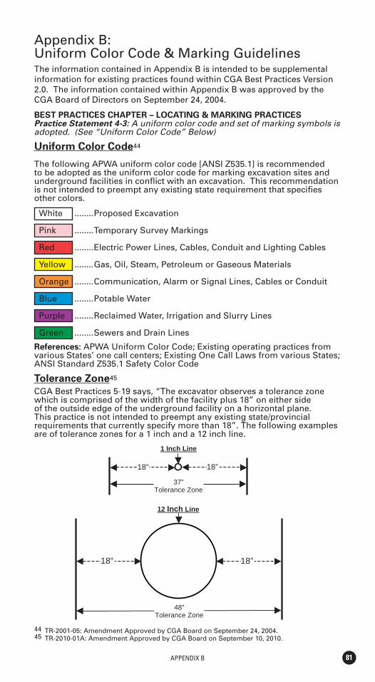
APPENDIX B 81
Appendix B:Uniform Color Code & Marking GuidelinesThe information contained in Appendix B is intended to be supplemental information for existing practices found within CGA Best Practices Version 2.0. The information contained within Appendix B was approved by the CGA Board of Directors on September 24, 2004.
BEST PRACTICES CHAPTER – LOCATING & MARKING PRACTICESPractice Statement 4-3: A uniform color code and set of marking symbols is adopted. (See “Uniform Color Code” Below)
Uniform Color Code44
The following APWA uniform color code [ANSI Z535.1] is recommended to be adopted as the uniform color code for marking excavation sites and underground facilities in conflict with an excavation. This recommendation is not intended to preempt any existing state requirement that specifies other colors.
White ........Proposed Excavation
Pink ........Temporary Survey Markings
Red ........Electric Power Lines, Cables, Conduit and Lighting Cables
Yellow ........Gas, Oil, Steam, Petroleum or Gaseous Materials
Orange ........Communication, Alarm or Signal Lines, Cables or Conduit
Blue ........Potable Water
Purple ........Reclaimed Water, Irrigation and Slurry Lines
Green ........Sewers and Drain Lines
References: APWA Uniform Color Code; Existing operating practices from various States’ one call centers; Existing One Call Laws from various States; ANSI Standard Z535.1 Safety Color Code
Tolerance Zone45
CGA Best Practices 5-19 says, “The excavator observes a tolerance zone which is comprised of the width of the facility plus 18” on either side of the outside edge of the underground facility on a horizontal plane. This practice is not intended to preempt any existing state/provincial requirements that currently specify more than 18”. The following examples are of tolerance zones for a 1 inch and a 12 inch line.
18” 18”
18” 18”
12 Inch Line
37” Tolerance Zone
48” Tolerance Zone
1 Inch Line
44 TR-2001-05: Amendment Approved by CGA Board on September 24, 2004.45 TR-2010-01A: Amendment Approved by CGA Board on September 10, 2010.
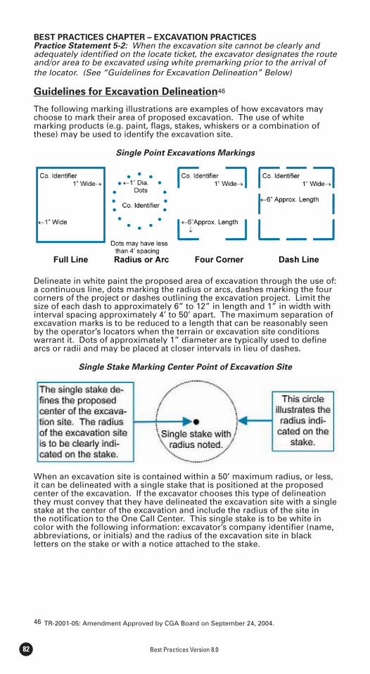
Best Practices Version 8.082
46 TR-2001-05: Amendment Approved by CGA Board on September 24, 2004.
BEST PRACTICES CHAPTER – EXCAVATION PRACTICESPractice Statement 5-2: When the excavation site cannot be clearly and adequately identified on the locate ticket, the excavator designates the route and/or area to be excavated using white premarking prior to the arrival of the locator. (See “Guidelines for Excavation Delineation” Below)
Guidelines for Excavation Delineation46
The following marking illustrations are examples of how excavators may choose to mark their area of proposed excavation. The use of white marking products (e.g. paint, flags, stakes, whiskers or a combination of these) may be used to identify the excavation site.
Single Point Excavations Markings
Delineate in white paint the proposed area of excavation through the use of: a continuous line, dots marking the radius or arcs, dashes marking the four corners of the project or dashes outlining the excavation project. Limit the size of each dash to approximately 6” to 12” in length and 1” in width with interval spacing approximately 4’ to 50’ apart. The maximum separation of excavation marks is to be reduced to a length that can be reasonably seen by the operator’s locators when the terrain or excavation site conditions warrant it. Dots of approximately 1” diameter are typically used to define arcs or radii and may be placed at closer intervals in lieu of dashes.
Single Stake Marking Center Point of Excavation Site
When an excavation site is contained within a 50’ maximum radius, or less, it can be delineated with a single stake that is positioned at the proposed center of the excavation. If the excavator chooses this type of delineation they must convey that they have delineated the excavation site with a single stake at the center of the excavation and include the radius of the site in the notification to the One Call Center. This single stake is to be white in color with the following information: excavator’s company identifier (name, abbreviations, or initials) and the radius of the excavation site in black letters on the stake or with a notice attached to the stake.
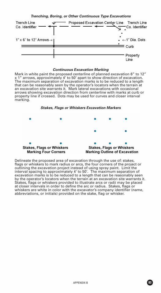
APPENDIX B 83
Trenching, Boring, or Other Continuous Type Excavations
Continuous Excavation Marking
Mark in white paint the proposed centerline of planned excavation 6” to 12” x 1” arrows, approximately 4’ to 50’ apart to show direction of excavation. The maximum separation of excavation marks is to be reduced to a length that can be reasonably seen by the operator’s locators when the terrain at an excavation site warrants it. Mark lateral excavations with occasional arrows showing excavation direction from centerline with marks at curb or property line if crossed. Dots may be used for curves and closer interval marking.
Stakes, Flags or Whiskers Excavation Markers
Delineate the proposed area of excavation through the use of: stakes, flags or whiskers to mark radius or arcs, the four corners of the project or outlining the excavation project instead of using spray paint. Limit the interval spacing to approximately 4‘ to 50’. The maximum separation of excavation marks is to be reduced to a length that can be reasonably seen by the operator’s locators when the terrain at an excavation site warrants it. Stakes, flags or whiskers provided to illustrate arcs or radii may be placed at closer intervals in order to define the arc or radius. Stakes, flags or whiskers are white in color with the excavator’s company identifier (name, abbreviations, or initials) provided on the stake, flag or whisker.
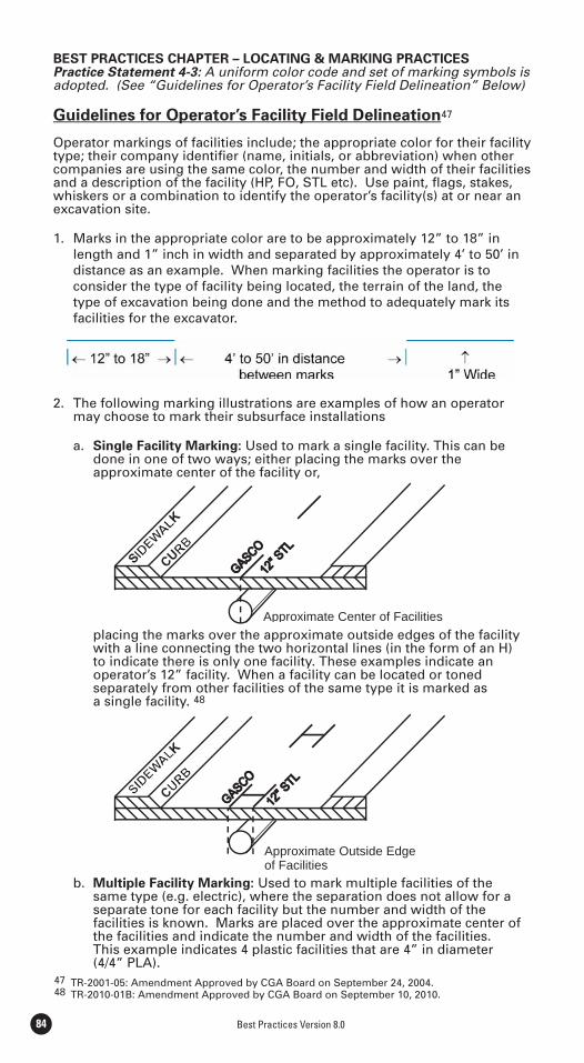
Best Practices Version 8.084
47 TR-2001-05: Amendment Approved by CGA Board on September 24, 2004.48 TR-2010-01B: Amendment Approved by CGA Board on September 10, 2010.
BEST PRACTICES CHAPTER – LOCATING & MARKING PRACTICES Practice Statement 4-3: A uniform color code and set of marking symbols is adopted. (See “Guidelines for Operator’s Facility Field Delineation” Below)
Guidelines for Operator’s Facility Field Delineation47
Operator markings of facilities include; the appropriate color for their facility type; their company identifi er (name, initials, or abbreviation) when other companies are using the same color, the number and width of their facilities and a description of the facility (HP, FO, STL etc). Use paint, fl ags, stakes, whiskers or a combination to identify the operator’s facility(s) at or near an excavation site.
1. Marks in the appropriate color are to be approximately 12” to 18” in length and 1” inch in width and separated by approximately 4’ to 50’ in distance as an example. When marking facilities the operator is to consider the type of facility being located, the terrain of the land, the type of excavation being done and the method to adequately mark its facilities for the excavator.
2. The following marking illustrations are examples of how an operator may choose to mark their subsurface installations
a. Single Facility Marking: Used to mark a single facility. This can be done in one of two ways; either placing the marks over the approximate center of the facility or,
placing the marks over the approximate outside edges of the facility with a line connecting the two horizontal lines (in the form of an H) to indicate there is only one facility. These examples indicate an operator’s 12” facility. When a facility can be located or toned separately from other facilities of the same type it is marked as a single facility. 48
b. Multiple Facility Marking: Used to mark multiple facilities of the same type (e.g. electric), where the separation does not allow for a separate tone for each facility but the number and width of the facilities is known. Marks are placed over the approximate center of the facilities and indicate the number and width of the facilities. This example indicates 4 plastic facilities that are 4” in diameter (4/4” PLA).
Approximate Center of Facilities
Approximate Outside Edge of Facilities
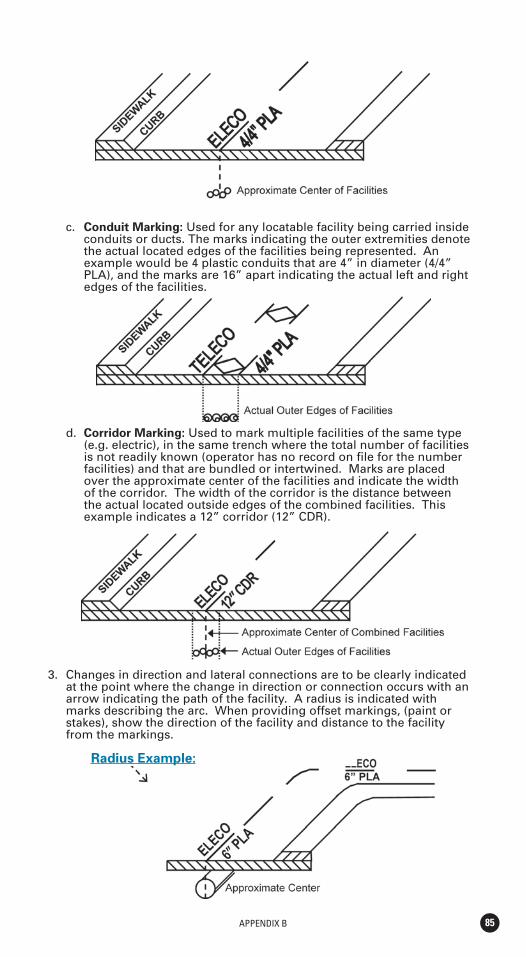
APPENDIX B 85
c. Conduit Marking: Used for any locatable facility being carried inside conduits or ducts. The marks indicating the outer extremities denote the actual located edges of the facilities being represented. An example would be 4 plastic conduits that are 4” in diameter (4/4” PLA), and the marks are 16” apart indicating the actual left and right edges of the facilities.
d. Corridor Marking: Used to mark multiple facilities of the same type (e.g. electric), in the same trench where the total number of facilities is not readily known (operator has no record on file for the number facilities) and that are bundled or intertwined. Marks are placed over the approximate center of the facilities and indicate the width of the corridor. The width of the corridor is the distance between the actual located outside edges of the combined facilities. This example indicates a 12” corridor (12” CDR).
3. Changes in direction and lateral connections are to be clearly indicated at the point where the change in direction or connection occurs with an arrow indicating the path of the facility. A radius is indicated with marks describing the arc. When providing offset markings, (paint or stakes), show the direction of the facility and distance to the facility from the markings.
Radius Example:
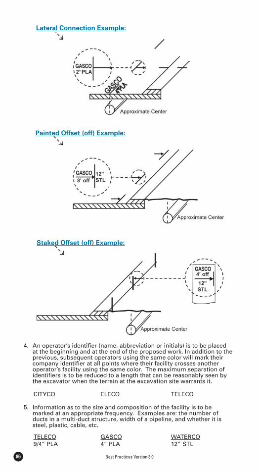
Best Practices Version 8.086
4. An operator’s identifier (name, abbreviation or initials) is to be placed at the beginning and at the end of the proposed work. In addition to the previous, subsequent operators using the same color will mark their company identifier at all points where their facility crosses another operator’s facility using the same color. The maximum separation of identifiers is to be reduced to a length that can be reasonably seen by the excavator when the terrain at the excavation site warrants it.
CITYCO ELECO TELECO
5. Information as to the size and composition of the facility is to be marked at an appropriate frequency. Examples are: the number of ducts in a multi-duct structure, width of a pipeline, and whether it is steel, plastic, cable, etc.
TELECO GASCO WATERCO 9/4” PLA 4” PLA 12” STL
Lateral Connection Example:
Painted Offset (off) Example:
Staked Offset (off) Example:
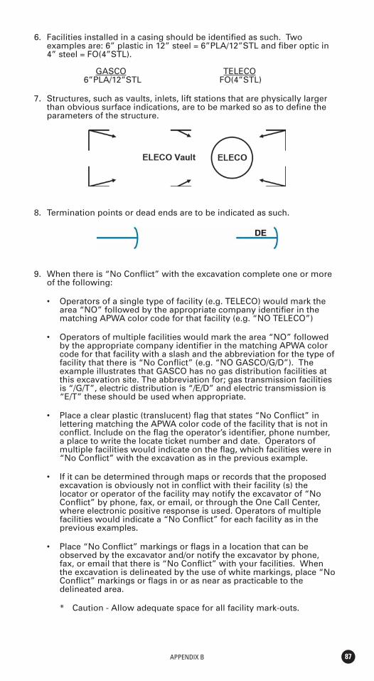
APPENDIX B 87
6. Facilities installed in a casing should be identified as such. Two examples are: 6” plastic in 12” steel = 6”PLA/12”STL and fiber optic in 4” steel = FO(4”STL).
GASCO TELECO 6”PLA/12”STL FO(4”STL)
7. Structures, such as vaults, inlets, lift stations that are physically larger than obvious surface indications, are to be marked so as to define the parameters of the structure.
8. Termination points or dead ends are to be indicated as such.
9. When there is “No Conflict” with the excavation complete one or more of the following:
area “NO” followed by the appropriate company identifier in the matching APWA color code for that facility (e.g. “NO TELECO”)
by the appropriate company identifier in the matching APWA color code for that facility with a slash and the abbreviation for the type of facility that there is “No Conflict” (e.g. “NO GASCO/G/D”). The example illustrates that GASCO has no gas distribution facilities at this excavation site. The abbreviation for; gas transmission facilities is “/G/T”, electric distribution is “/E/D” and electric transmission is “E/T” these should be used when appropriate.
lettering matching the APWA color code of the facility that is not in conflict. Include on the flag the operator’s identifier, phone number, a place to write the locate ticket number and date. Operators of multiple facilities would indicate on the flag, which facilities were in “No Conflict” with the excavation as in the previous example.
excavation is obviously not in conflict with their facility (s) the locator or operator of the facility may notify the excavator of “No Conflict” by phone, fax, or email, or through the One Call Center, where electronic positive response is used. Operators of multiple facilities would indicate a “No Conflict” for each facility as in the previous examples.
observed by the excavator and/or notify the excavator by phone, fax, or email that there is “No Conflict” with your facilities. When the excavation is delineated by the use of white markings, place “No Conflict” markings or flags in or as near as practicable to the delineated area.
* Caution - Allow adequate space for all facility mark-outs.

Best Practices Version 8.088
“No Conflict” indicates; that the operator providing the “No Conflict” has no facilities within the scope of the delineation, or when there is no delineation, there are no facilities within the work area as described on the locate ticket.
Color Code Identifiers
White Proposed Excavation Pink Temporary Survey Markings Red Electric Power Lines, Cables, Conduit and Lighting Cables Yellow Gas, Oil, Steam, Petroleum or Gaseous Materials Orange Communication, Alarm or Signal Lines, Cables or Conduit Blue Potable Water Purple Reclaimed Water, Irrigation and Slurry Lines Green Sewers and Drain Lines
Common Abbreviations:
Facility Identifier
CH Chemical E Electric FO Fiber Optic G Gas LPG Liquefied Petroleum Gas PP Petroleum Products RR Railroad Signal S Sewer SD Storm Drain SS Storm Sewer SL Street Lighting STM Steam SP Slurry System TEL Telephone TS Traffic Signal TV Television W Water W Reclaimed Water “Purple”
Underground Construction Descriptions
C Conduit CDR Corridor D Distribution Facility DB Direct Buried DE Dead End JT Joint Trench HP High Pressure HH Hand Hole MH Manhole PB Pull Box R Radius STR Structure (vaults, junction boxes, inlets, lift stations) T Transmission Facility
NO CITYCO/WNO TELECONO GASCO/G/D/TNO ELECO
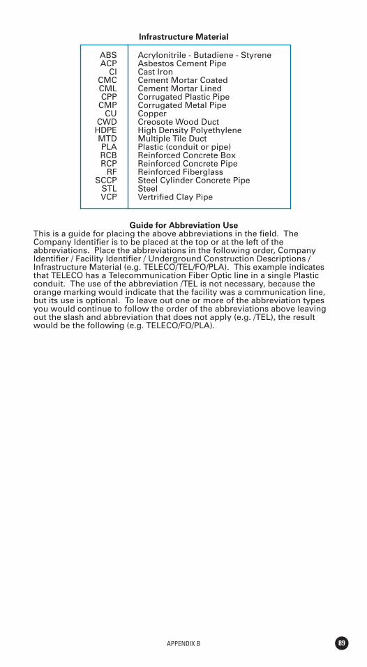
APPENDIX B 89
Infrastructure Material
ABS Acrylonitrile - Butadiene - Styrene ACP Asbestos Cement Pipe CI Cast Iron CMC Cement Mortar Coated CML Cement Mortar Lined CPP Corrugated Plastic Pipe CMP Corrugated Metal Pipe CU Copper CWD Creosote Wood Duct HDPE High Density Polyethylene MTD Multiple Tile Duct PLA Plastic (conduit or pipe) RCB Reinforced Concrete Box RCP Reinforced Concrete Pipe RF Reinforced Fiberglass SCCP Steel Cylinder Concrete Pipe STL Steel VCP Vertrified Clay Pipe
Guide for Abbreviation UseThis is a guide for placing the above abbreviations in the field. The Company Identifier is to be placed at the top or at the left of the abbreviations. Place the abbreviations in the following order, Company Identifier / Facility Identifier / Underground Construction Descriptions / Infrastructure Material (e.g. TELECO/TEL/FO/PLA). This example indicates that TELECO has a Telecommunication Fiber Optic line in a single Plastic conduit. The use of the abbreviation /TEL is not necessary, because the orange marking would indicate that the facility was a communication line, but its use is optional. To leave out one or more of the abbreviation types you would continue to follow the order of the abbreviations above leaving out the slash and abbreviation that does not apply (e.g. /TEL), the result would be the following (e.g. TELECO/FO/PLA).

Best Practices Version 8.09090
For additional information on the Common Ground Alliance or to learn how to become a member, visit the CGA web site at
www.commongroundalliance.com
APPENDIX C 91
Appendix C:Sample Forms/Reports/Releases
During the Common Ground Study, the Reporting and Evaluation Task Team drafted a sample report form (originally referred to as figure 9-1) to demonstrate what may be reported when collecting damage prevention information. The team created this sample form, on the following page, using the best practices from one call center, regulatory agency, facility, locator, excavator, and industry group report forms. The form was created to be used to gather data from all stakeholders involved in the damage prevention process, including facility owners/operators, excavators, and locators.
Appendix C Sample Form: The 9-1 form was the basis for the develop-ment of the CGA’s Damage Information Reporting Tool (DIRT) launched in December 2003. The Data Reporting & Evaluation Committee approved minor modifications to the original 9-1 form when creating DIRT. These modifications were later approved by the CGA Best Practices Committee. The approved DIRT form has been included in Appendix C. To review the electronic version and tool, visit www.cga-dirt.com.
References: The following list of references was used as examples during the Task Team’s discussions and the development of the composite report-ing form (9-1). These sources do not include all stakeholders that may report any of the same information shown on the sample form.
Safety Through Excavation Damage Prevention (NTSB/SS-97-01).
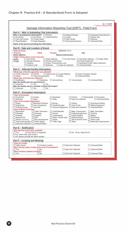
Best Practices Version 8.092
Rev: 1/16/2009 ‘*’ indicates a Required Field
Damage Information Reporting Tool (DIRT) - Field Form
Part A – Who is Submitting This Information Who is providing the information? Electric Engineer/Design Equipment Manufacturer
Excavator Insurance Liquid Pipeline Locator Natural Gas One-Call Center Private Water Public Works Railroad Road Builders State Regulator Telecommunications Unknown/Other
Name of the person providing the information:
Part B - Date and Location of Event*Date of Event: (MM/DD/YYYY)*Country *State *County City Street address Nearest Intersection *Right of Way where event occurred Public: City Street State Highway County Road Interstate Highway Public-Other Private: Private Business Private Land Owner Private Easement Pipeline Power /Transmission Line Dedicated Public Utility Easement Federal Land Railroad Data not collected Unknown/Other
Part C – Affected Facility Information*What type of facility operation was affected?
Cable Television Electric Natural Gas Liquid Pipeline Sewer (Sanitary Sewer) Steam Telecommunications Water Unknown/Other
*What type of facility was affected? Distribution Gathering Service/Drop Transmission Unknown/Other
Was the facility part of a joint trench? Unknown Yes No
Was the facility owner a member of One-Call Center? Unknown Yes No
Part D – Excavation Information *Type of Excavator
Contractor County Developer Farmer Municipality Occupant Railroad State Utility Data not collected Unknown/Other
*Type of Excavation Equipment Auger Backhoe/Trackhoe Boring Drilling Directional Drilling Explosives Farm Equipment Grader/Scraper Hand Tools Milling Equipment Probing Device Trencher Vacuum Equipment Data Not Collected Unknown/Other
*Type of Work Performed Agriculture Cable Television Curb/Sidewalk Bldg. Construction Bldg. Demolition Drainage Driveway Electric Engineering/Survey Fencing Grading Irrigation Landscaping Liquid Pipeline Milling Natural Gas Pole Public Transit Auth. Railroad Maint. Road Work Sewer (San/Storm) Site Development Steam Storm Drain/Culvert Street Light Telecommunication Traffic Signal Traffic Sign Water Waterway Improvement Data Not Collected Unknown/Other
Part E – Notification *Was the One-Call Center notified?
Yes (If Yes, Part F is required) No (If No, Skip Part F) If Yes, which One-Call Center? If Yes, please provide the ticket number
Part F - Locating and Marking *Type of Locator
Utility Owner Contract Locator Data Not Collected Unknown/Other *Were facility marks visible in the area of excavation?
Yes No Data Not Collected Unknown/Other *Were facilities marked correctly?
Yes No Data Not Collected Unknown/Other
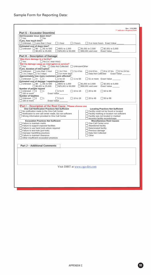
APPENDIX C 93
Sample Form for Reporting Data:
Rev: 1/16/2009 ‘*’ indicates a Required Field
Part G – Excavator Downtime Did Excavator incur down time?
Yes No If yes, how much time?
Unknown Less than 1 hour 1 hour 2 hours 3 or more hours Exact Value ______ Estimated cost of down time?
Unknown $0 $1 to 500 $501 to 1,000 $1,001 to 2,500 $2,501 to 5,000 $5,001 to 25,000 $25,001 to 50,000 $50,001 and over Exact Value ______
Part H – Description of Damage *Was there damage to a facility?
Yes No (i.e. near miss) *Did the damage cause an interruption in service?
Yes No Data Not Collected Unknown/Other If yes, duration of interruption
Unknown Less than 1 hour 1 to 2 hrs 2 to 4 hrs 4 to 8 hrs 8 to 12 hrs 12 to 24 hrs 1 to 2 days 2 to 3 days 3 or more days Data Not Collected Exact Value _______
Approximately how many customers were affected? Unknown 0 1 2 to 10 11 to 50 51 or more Exact Value _______
Estimated cost of damage / repair/restoration Unknown $0 $1 to 500 $501 to 1,000 $1,001 to 2,500 $2,501 to 5,000
$5,001 to 25,000 $25,001 to 50,000 $50,001 and over Exact Value ______ Number of people injured
Unknown 0 1 2 to 9 10 to 19 20 to 49 50 to 99 100 or more Exact Value _______
Number of fatalities Unknown 0 1 2 to 9 10 to 19 20 to 49 50 to 99 100 or more Exact Value _______
*Part I – Description of the Root Cause *Please choose one One-Call Notification Practices Not Sufficient Locating Practices Not Sufficient
No notification made to the One-Call Center Facility could not be found or located Notification to one-call center made, but not sufficient Facility marking or location not sufficient Wrong information provided to One Call Center Facility was not located or marked
Incorrect facility records/maps Excavation Practices Not Sufficient Miscellaneous Root Causes
Failure to maintain marks One-Call Center error Failure to support exposed facilities Abandoned facility Failure to use hand tools where required Deteriorated facility Failure to test-hole (pot-hole) Previous damage Improper backfilling practices Data Not Collected Failure to maintain clearance Other Other insufficient excavation practices
Visit DIRT at www.cga-dirt.com
Part J – Additional Comments
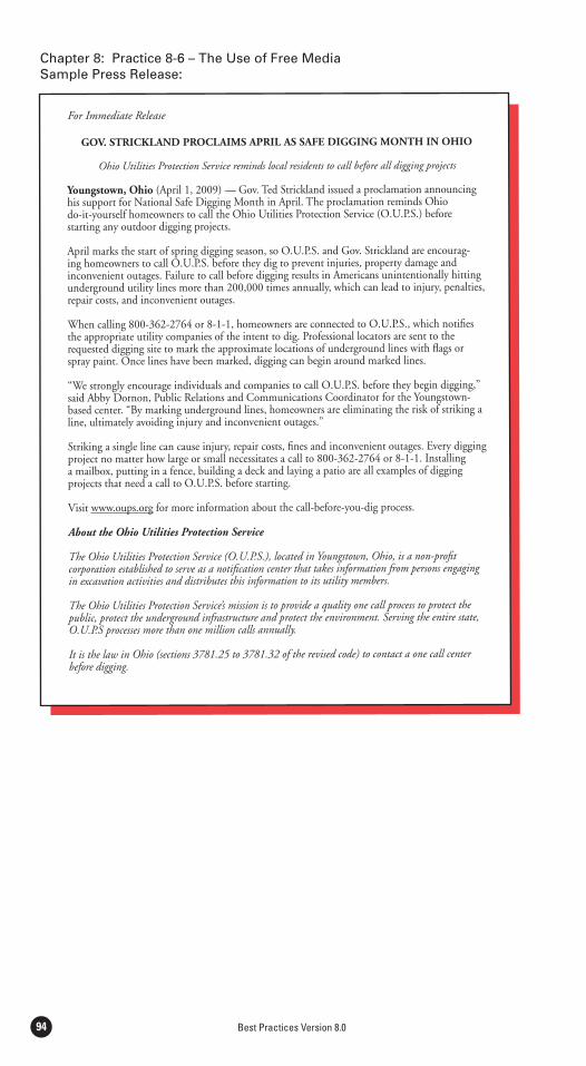
Best Practices Version 8.094
For Immediate Release
GOV. STRICKLAND PROCLAIMS APRIL AS SAFE DIGGING MONTH IN OHIO
Ohio Utilities Protection Service reminds local residents to call before all digging projects
Youngstown, Ohio (April 1, 2009) — Gov. Ted Strickland issued a proclamation announcing his support for National Safe Digging Month in April. The proclamation reminds Ohio do-it-yourself homeowners to call the Ohio Utilities Protection Service (O.U.P.S.) before starting any outdoor digging projects.
April marks the start of spring digging season, so O.U.P.S. and Gov. Strickland are encourag-ing homeowners to call O.U.P.S. before they dig to prevent injuries, property damage and inconvenient outages. Failure to call before digging results in Americans unintentionally hitting underground utility lines more than 200,000 times annually, which can lead to injury, penalties, repair costs, and inconvenient outages.
When calling 800-362-2764 or 8-1-1, homeowners are connected to O.U.P.S., which notifies the appropriate utility companies of the intent to dig. Professional locators are sent to the requested digging site to mark the approximate locations of underground lines with flags or spray paint. Once lines have been marked, digging can begin around marked lines.
“We strongly encourage individuals and companies to call O.U.P.S. before they begin digging,” said Abby Dornon, Public Relations and Communications Coordinator for the Youngstown-based center. “By marking underground lines, homeowners are eliminating the risk of striking a line, ultimately avoiding injury and inconvenient outages.”
Striking a single line can cause injury, repair costs, fines and inconvenient outages. Every digging project no matter how large or small necessitates a call to 800-362-2764 or 8-1-1. Installing a mailbox, putting in a fence, building a deck and laying a patio are all examples of digging projects that need a call to O.U.P.S. before starting.
Visit www.oups.org for more information about the call-before-you-dig process.
About the Ohio Utilities Protection Service
The Ohio Utilities Protection Service (O.U.P.S.), located in Youngstown, Ohio, is a non-profit corporation established to serve as a notification center that takes information from persons engaging in excavation activities and distributes this information to its utility members.
The Ohio Utilities Protection Service’s mission is to provide a quality one call process to protect the public, protect the underground infrastructure and protect the environment. Serving the entire state, O.U.P.S processes more than one million calls annually.
It is the law in Ohio (sections 3781.25 to 3781.32 of the revised code) to contact a one call center before digging.
Sample Press Release:
APPENDIX D 95
Appendix D:Additional References
The references contained in Appendix D are intended to be supplemental references for existing and/or new practices found within the CGA Best Practices.
Trenchless ExcavationChapter 2: Practice 2-13
Chapter 4: Practice 4-19
Chapter 5: Practice 5-29
References: Provide references for any existing practices cited in Origin/Rationale
American Gas Association (AGA), “Directional Drilling Damage Prevention Guidelines for the Natural Gas Industry” Technical Note December 30, 2004.
American Society of Civil Engineers, ASCE Manuals and Reports on Engi-neering Practice No. 89, “Pipeline Crossings”, 1996.
Bennett, R.D., S.T. Ariaratnam, and C. Como “Horizontal Directional Drill-ing Good Practices Guidelines.” HDD Consortium, Washington, DC, ISBN 1-928984-13-4, 2001
California Department of Transportation, CALTRANS, “CALTRANS En-
July 14, 2003.”
Directional Crossing Contractors Association (DCCA), “Guidelines for Suc-cessful Directional Crossing Survey Standards.” Dallas, TX, 1999.
Directional Crossing Contractors Association (DCCA), “Horizontal Drilling Safe Operations Guidelines.” Dallas, TX, 1995.
Guided Horizontal Drilling to Install Gas Distribution Piping”, GRI-96-0368, September 1996.
National Transportation Safety Board, “Safety Study: Protecting Public Safe-ty Through Excavation Damage Prevention.” Washington, DC, Dec. 1999.
National Utility Contractors Association (NUCA), “Trenchless Construction Methods and Soil Compatibility Manual, 3rd Edition.” Washington, DC.
National Utility Locating Contractors Association (NULCA), “Excavation Practices & Procedures for Damage Prevention.” Spooner, WI, 1996.

Best Practices Version 8.096
For additional information on the Common Ground Alliance or to learn how to become a member, visit the CGA web site at
www.commongroundalliance.com
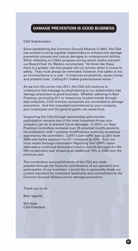
97
DAMAGE PREVENTION IS GOOD BUSINESS
CGA Stakeholders:
Since establishing the Common Ground Alliance in 2001, the CGA has worked to bring together stakeholders to enhance the damage prevention process and reduce damages to underground utilities. When refl ecting on CGA’s progress during recent media outreach, our Board Chair Vic Weston commented, “At times like these, there is a greater risk that people will cut corners when it comes to safety. They must always be reminded, however, that safety is not
and protects lives. Calling 811 makes great business sense.”
As we turn the corner into 2011, the CGA will continue to underscore this message by emphasizing to our stakeholders that damage prevention is good business. Whether adhering to Best Practices, promoting 811 or measuring incident trends through data collection, CGA member companies are committed to damage prevention. And this important commitment to your company, your employees and the general public can saves lives.
Supporting the CGA through sponsorship and member participation remains one of the most important things your company can do to prevent future damages. In 2010, our Best Practices Committee reviewed over 25 potential modifi cations to the publication with 7 practice modifi cations receiving consensus approval by the committee. Call811.com traffi c was up 35% from 2009 and media exposure for 811 increased by 53%. And, our most recent Damage Information Reporting Tool (DIRT) report estimates a continued downward trend in overall damages for the fi fth consecutive year dropping an additional 18% in 2009 over the previous year.
The tremendous accomplishments of the CGA are made possible through the fi nancial contributions of our sponsors and participation of our members. I would like to personally thank our current members for consistent leadership and commitment to the Common Ground Alliance and to damage prevention.
Thank you to all.
Best regards,
Bob KippCGA President
CGA Member Organizations3MAEGIS Insurance Service, Inc.AGL ResourcesAir Products and Chemicals, Inc.Alabama 1 CallAlberta One Call CorporationAlliance PipelineAlliant EnergyAmerican Gas AssociationAmerican Petroleum InstituteAmerican Public Gas AssociationAmerican Public Works AssociationArizona Blue StakeArkansas One Call Systems, Inc.Associated General Contractors of AmericaAssociation of American RailroadsAssociation of Oil Pipe LinesAT&TAtmos Energy CorporationAvista CorporationBadger Daylighting CorporationBaltimore Gas and Electric CompanyBP AmericaBP USPLBuckeye Partners, LPCanadian Gas AssociationCenterPoint EnergyCheniere PipelineChesapeake MidstreamChevron CorporationCitizens Gas & Coke UtilityCity Of Fresno WaterCity of MesaCity Utilities of Springfield, MissouriColonial PipelineColorado 811ConocoPhillipsConsolidated Edison of New YorkConsolidated Utility Services, Inc.Consumers EnergyCorinth Gas & WaterCoServ Gas, Ltd.CPN PipelineCountryMarkDakota Gasification CompanyDeere & CompanyDig Safely New York Inc.Diggers Hotline, Inc.DigNet of New York City & Long IslandDitch WitchDominion East OhioEl Paso CorporationELM Locating & Utility ServicesEnbridge Energy Company, Inc.Enterprise ProductsExplorer Pipeline CompanyExxonMobil Pipeline CompanyGeorgia 811Gopher State One CallGreenville Utilities CommissionGreer CPW

CGA Member OrganizationsGwinnett Co. Department of Water ResourcesIndiana 811Infrastructure ResourcesInterstate Natural Gas Association of AmericaIntrenJULIE, Inc. (Illinois One-Call System)Kansas One CallKentucky 811Kern River Gas TransmissionKinder MorganKnoxville Utilities BoardKoch Pipeline Company LPKrylon Products GroupLake Apopka Natural Gas DistrictLevel 3 CommunicationsLG&E EnergyLOOP, LLCLos Angeles Department of Water & PowerMagellan Midstream Partners, L.P.Marathon Pipe Line, LLCMDU ResourcesMetrotechMiddle Tennessee Natural Gas DistrictMISS DIG System, IncMississippi 811Missouri One CallMobile Gas Services CorpNational Association of Pipeline Safety RepresentativesNational Association of State Fire MarshalsNational GridNational Telecommunications Damage Prevention CouncilNational Utility Contractors AssociationNational Utility Locating Contractors AssociationNCRA/Jayhawk Pipeline LLCNew Jersey Natural GasNew Mexico Gas CompanyNicor GasNiSourceNorth Carolina 811Northern Natural GasNorthWest Natural GasNuStar Energy LPOhio Utilities Protection ServiceOkaloosa Gas DistrictOne Call ConceptsOne Call of WyomingONEOKONEOK PartnersOntario One CallOsinergminPacific Gas and Electric CompanyPanhandle EnergyParadigmPennsylvania 811Peoples EnergyPeoples Natural Gas Company, LLCPhiladelphia Gas WorksPiedmont Natural GasPinnacle West Capital Corp/APSPipeline & Hazardous Materials Safety AdministrationPlains All American
Plains All American Pipeline, L.P.Portland General ElectricPortland Pipe Line CorporationPPL Interstate Energy CompanyProgress EnergyPublic Service Electric & Gas CompanyPuget Sound EnergyQuestar Gas CompanyQwest Local NetworkRhino Marking & Protection SystemsRonkin ConstructonScana CorporationShell Pipeline Company LPSierra Pacific ResourcesSouth Jersey Gas CompanySouthern California Gas CompanySouthern Star Central Gas Pipeline, IncSouthwest Gas CorporationSPEC Services, Inc.Spectra EnergySuncor EnergySunoco Pipeline, L.P.Sunshine State One Call of FloridaTarga ResourcesTeam FishelTECO-Peoples GasTennessee 811Texas 811TransCanadaTransMontaigne Product ServicesTranswestern Pipeline CompanyTravelersUGI Utilities, Inc.Underground Safety Alliance (USA)Underground Service Alert - Southern CaliforniaUnibar Damage Prevention GroupUnited States Infrastructure CorporationUSA NorthVac-Tron EquipmentValero Energy Corp.Vectren Energy DeliveryVerizonVirginia Utility Protection Service, Inc.Washington 811Washington GasWE EnergiesWilliamsWisconsin Public Service CorporationWolverine Pipe Line CompanyXCEL Energy Services
CGA Member Organizations
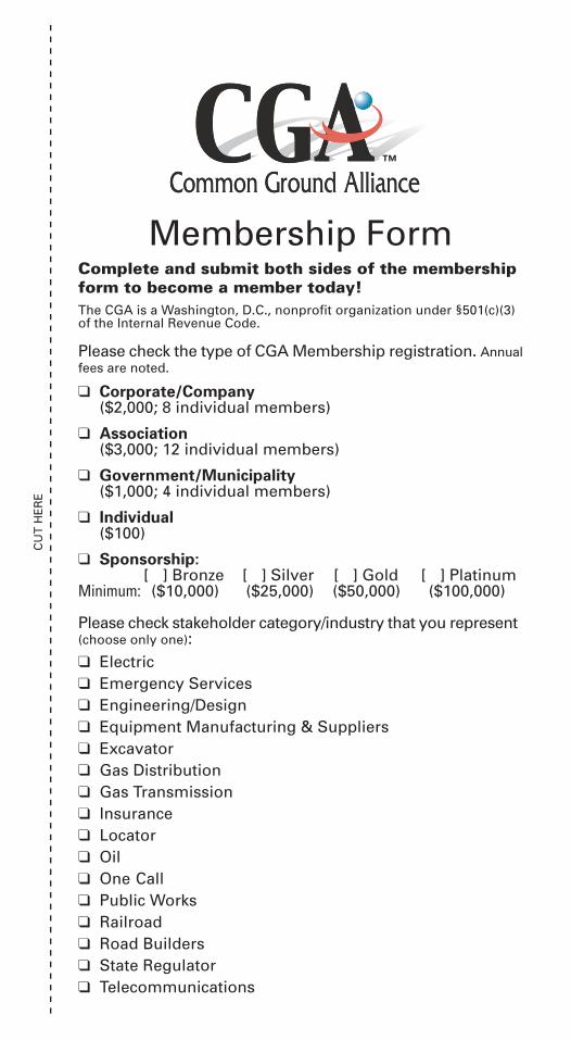
Membership FormComplete and submit both sides of the membershipform to become a member today!The CGA is a Washington, D.C., nonprofit organization under §501(c)(3)of the Internal Revenue Code.
Please check the type of CGA Membership registration. Annualfees are noted.
❑ Corporate/Company($2,000; 8 individual members)
❑ Association($3,000; 12 individual members)
❑ Government/Municipality($1,000; 4 individual members)
❑ Individual($100)
❑ Sponsorship:[ ] Bronze [ ] Silver [ ] Gold [ ] Platinum
Minimum: ($10,000) ($25,000) ($50,000) ($100,000)
Please check stakeholder category/industry that you represent(choose only one):❑ Electric❑ Emergency Services❑ Engineering/Design❑ Equipment Manufacturing & Suppliers❑ Excavator❑ Gas Distribution❑ Gas Transmission❑ Insurance❑ Locator❑ Oil❑ One-Call❑ Public Works❑ Railroad❑ Road Builders❑ State Regulator❑ Telecommunications
CU
T H
ER
E
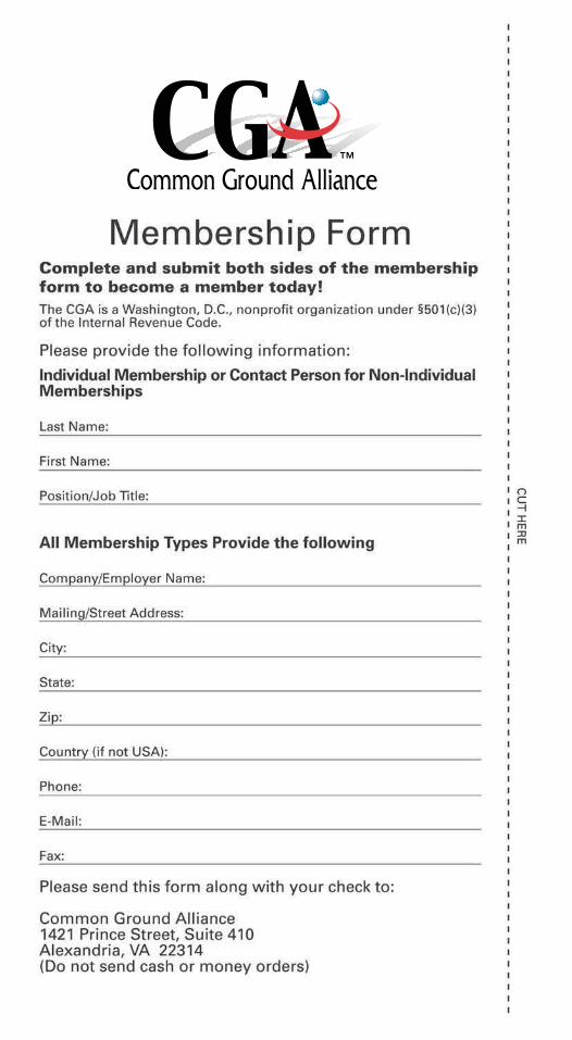
CG
A B
ron
ze S
po
nso
rs
Association of Oil Pipe Lines
Associated General Contractors of America
National Association ofPipeline Safety Representatives
National Associationof State Fire Marshals
AEGIS Insurance Service, Inc.
American Petroleum Institute
Interstate Natural Gas Associationof America
®
Public Service Electric & Gas Company
International Partner
National Utility Contractors Association ORGANISMO SUPERVISOR DE LA INVERSIÒN EN ENERGÍA Y MINERÍA
CG
A P
lati
nu
m S
po
nso
rs
CG
A G
old
Spo
nsor
sC
GA
Sil
ver S
po
nso
rs
Colonial Pipeline
Shell Pipeline Company LP
BP America
Pipeline and Hazardous Materials Safety Administration
American Gas Association
®
Damage Prevention is a Shared Responsibility
Whether you are a facility owner/operator, locator, design professional, one call center employee, excavator/contractor or other stakeholder, ensuring the safety of those who work or live in the vicinity of underground facilities and protecting our vital services is everyone’s responsibility.
In 1999, the U.S. Department of Transportation sponsored the Common Ground Study of One Call Systems and Damage Prevention Best Practices. Following the completion of the Study, the CGA was established to foster the spirit of shared responsibility among all parties involved in the damage prevention process.
The CGA is now comprised of almost 1,400 volunteer members who work together to identify and promote best practices aimed at keeping communities and the environment safe from the undesired consequences of damage to buried utilities. CGA works cooperatively to enhance underground damage prevention by:
underground facilities;
as those embodied in the Common Ground Study;
and dissemination.
For additional information on the Common Ground Alliance or to learn how to become a member,
visit the CGA web site at www.commongroundalliance.com.
.


