Embed Size (px)
Citation preview

HydraMaster11015 47th Avenue West
Mukilteo, Washington 98275
MAN-46585 Rev. A, May 20, 2015(P/N 000-182-418)
No part of this manual may be reproduced or used in any form or by any means (i.e. graphic, electronic, photocopying or electronic retrieval systems) without the express written permission of HydraMaster. Specifications and information in this document are
subject to change without prior notice. All rights reserved. © 2015 HydraMaster
Boxxer 318 - 2015Owner’s Manual
*000-182-418*


i: Boxxer 318 Owner’s Manual
Table of ContentsGENERAL INFORMATION ........................................................................... SECTION 1
Contact Information ........................................................................... 1-3Warnings, Cautions and Notices ....................................................... 1-4Responsibilities ................................................................................. 1-8System Concept ................................................................................ 1-10Machine Specifications ...................................................................... 1-11High Altitude Operation ..................................................................... 1-13Local Water Precautions .................................................................... 1-13
CLEANING AND CHEMICALS ..................................................................... SECTION 2Precautions ........................................................................................ 2-1Preparing the Carpet for Extraction ................................................... 2-2Rinse and Recover ............................................................................ 2-2Overwetting........................................................................................ 2-3Streaking............................................................................................ 2-3Cleaning Tool Tips ............................................................................. 2-4
OPERATING INSTRUCTIONS ..................................................................... SECTION 3Start-up Procedure ............................................................................ 3-1Water Extraction Procedure ............................................................... 3-4Shut-down Procedure ........................................................................ 3-4
MACHINE MAINTENANCE .......................................................................... SECTION 4Operational Maintenance................................................................... 4-2High Pressure Pump Maintenance .................................................... 4-4Vacuum System Maintenance ........................................................... 4-8Descaling Procedure (Required) ....................................................... 4-9Freeze Guarding ................................................................................ 4-10Tensioning the Pump Drive Belt......................................................... 4-12
WATER AND CHEMICAL SYSTEM ............................................................. SECTION 5Water and Chemical Flow Operation ................................................. 5-1
ELECTRICAL SYSTEM ................................................................................ SECTION 6

Boxxer 318 Owner’s Manual: ii
TROUBLESHOOTING ................................................................................. SECTION 7Heating System ................................................................................. 7-2Chemical System ............................................................................... 7-3Engine................................................................................................ 7-5High Pressure System ....................................................................... 7-9Vacuum System ................................................................................. 7-11
ASSEMBLIES AND PARTS LIST ................................................................. SECTION 8Console Assembly Parts List ............................................................. 8-8Frame Assembly Parts List ................................................................ 8-11Engine Assembly Parts List ............................................................... 8-14Blower Assembly Parts List ............................................................... 8-16Pump Assembly Parts List ................................................................. 8-18Heat Exchanger Assembly Parts List................................................. 8-20Silencer Assembly Parts List ............................................................. 8-21Water Box Assembly Parts List .......................................................... 8-23Dash Assembly Parts List .................................................................. 8-26Differential Check Valve Assembly Parts List .................................... 8-27By-Pass Valve Assembly Parts List ................................................... 8-28Orifice Assembly Parts List ................................................................ 8-29Idler Pulley Assembly Parts List......................................................... 8-30Exhaust Assembly Parts List ............................................................. 8-3165 Gallon Universal Recovery Tank (URT) Assembly Parts List ....... 8-34100 Gallon Universal Recovery Tank (URT) Assembly Parts List ..... 8-36100 Gallon Universal Recovery Tank (URT) Cover Assembly Parts List ................................................................. 8-37Vacuum Relief Valve Assembly Parts List ......................................... 8-3870 Gallon Fresh Water Tank (FWT) Assembly Parts List................... 8-41Dura-Flow APO 90 Degree Assembly Parts List................................ 8-43APO Pump Assembly Parts List ........................................................ 8-44APO Connection Kit Assembly Parts List .......................................... 8-45Hose Routings ................................................................................... 8-46
HOW TO ORDER PARTS ............................................................................ SECTION 9Warranty Parts Orders ....................................................................... 9-1Parts Orders ...................................................................................... 9-1Emergencies ...................................................................................... 9-1
iii: Boxxer 318 Owner’s Manual
WARRANTY INFORMATION ....................................................................... SECTION 10Blower ............................................................................................... 10-1High Pressure Water Pump .............................................................. 10-1Recovery Tank .................................................................................. 10-2Chemical System .............................................................................. 10-2Control Panel .................................................................................... 10-2Vacuum and Solution Hoses ............................................................. 10-2Cleaning Wand ................................................................................. 10-2Water Heating System ...................................................................... 10-2Hard Water Deposits ........................................................................ 10-2Warranty Procedure ........................................................................... 10-3
ACCESSORIES AND CHEMICAL SOLUTIONS .......................................... SECTION 11

Boxxer 318 Owner’s Manual: iv
List of FiguresFigure 1-1. Hard Water Map of Mainland United States ........................................... 1-14
Figure 3-1. Location of Throttle, Choke and Pump-In/Pump Clutch Switch ............... 3-1Figure 3-2. Front View of Boxxer 318 Console ........................................................... 3-2Figure 3-3. Side View of Boxxer 318 Console ............................................................ 3-3
Figure 4-1. Servicing the Valves ................................................................................. 4-5Figure 4-2. Recirculation Fitting.................................................................................. 4-9
Figure 5-1. Flow Diagram - View 1 of 3 ...................................................................... 5-3Figure 5-2. Flow Diagram - View 2 of 3 ...................................................................... 5-4Figure 5-3. Flow Diagram - View 3 of 3 ...................................................................... 5-5
Figure 6-1. Electrical Schematic ................................................................................. 6-3Figure 6-2. Wiring Diagram - View 1 of 2 ................................................................... 6-4Figure 6-3. Wiring Diagram - View 2 of 2 ................................................................... 6-5
Figure 8-1. Adhesive/Sealant Material Reference ...................................................... 8-2Figure 8-2. Console Assembly - View 1 of 5 ............................................................... 8-3Figure 8-3. Console Assembly - View 2 of 5 ............................................................... 8-4Figure 8-4. Console Assembly - View 3 of 5 ............................................................... 8-5Figure 8-5. Console Assembly - View 4 of 5 ............................................................... 8-6Figure 8-6. Console Assembly - View 5 of 5 ............................................................... 8-7Figure 8-7. Frame Assembly - View 1 of 2 ................................................................. 8-9Figure 8-8. Frame Assembly -View 2 of 2 ................................................................ 8-10Figure 8-9. Engine Assembly - Part 1 of 2 ................................................................ 8-12
Figure 8-10. Engine Assembly - Part 2 of 2 .............................................................. 8-13Figure 8-11. Blower Assembly - View 1 of 2 ............................................................. 8-15Figure 8-12. Blower Assembly - View 2 of 2 ............................................................. 8-16Figure 8-13. Pump Assembly - View 1 of 2 .............................................................. 8-17Figure 8-14. Pump Assembly - View 2 of 2 .............................................................. 8-18Figure 8-15. Heat Exchanger Assembly ................................................................... 8-19Figure 8-16. Silencer Assembly ................................................................................ 8-21Figure 8-17. Water Box Assembly ............................................................................ 8-22Figure 8-18. Dash Assembly - View 1 of 2 ............................................................... 8-24Figure 8-19. Dash Assembly - View 2 of 2 ............................................................... 8-25

v: Boxxer 318 Owner’s Manual
Figure 8-20. Differential Check Valve Assembly ....................................................... 8-27Figure 8-21. By-Pass Valve Assembly ...................................................................... 8-28Figure 8-22. Orifice Assembly .................................................................................. 8-29Figure 8-23. Idler Pulley Assembly ........................................................................... 8-30Figure 8-24. Exhaust Assembly ................................................................................ 8-31Figure 8-25. 65 Gallon Universal Recovery Tank (URT) Assembly View 1 of 2 ........................................................................................... 8-32Figure 8-26. 65 Gallon Universal Recovery Tank (URT) Assembly - View 2 of 2 ..... 8-33Figure 8-27. 100 Gallon Universal Recovery Tank (URT) Assembly ........................ 8-35Figure 8-28. 100 Gallon Universal Recovery Tank (URT) Cover Assembly ............. 8-37Figure 8-29. Vacuum Relief Valve Assembly ........................................................... 8-38
Figure 8-30. 70 Gallon Fresh Water Tank (FWT) Assembly - View 1 of 2 ................ 8-39Figure 8-31. 70 Gallon Fresh Water Tank (FWT) Assembly View 2 of 2 .................. 8-40Figure 8-32. Dura-Flow APO 90 Degree Assembly .................................................. 8-42Figure 8-33. APO Pump Assembly ........................................................................... 8-44Figure 8-34. APO Connection Kit ............................................................................. 8-45

Boxxer 318 Owner’s Manual: vi

1-1: General Information
1- General InformationThe Boxxer™ 318 is a carefully engineered truckmount by HydraMaster for carpet cleaning, upholstery cleaning and water extraction/restoration as well.
The system utilizes an internal combustion engine to provide the power necessary to turn both a blower (also referred to as a vacuum pump) and a high pressure water pump.
The heat of the engine and blower exhausts is transferred to the high pressure water in the heat exchanger of the system.
Finally, the chemical is injected into the pressurized water stream and the heated solution is delivered to the cleaning tool.
The solution is recovered by the vacuum generated by the blower and is collected in the recovery tank for proper disposal.
To provide an on-board fresh water source in a space-saving configuration, the 70 Gallon Sub-Mount RMT Freshwater Tank (P/N 000-163-212) is available as an option.

General Information: 1-2
It is the purpose of this manual to help the technician properly understand, maintain and service the truckmount. By following these guidelines carefully, you can expect years of reliable operation.
This section contains the following information:
� Contact Information � Warnings, Cautions and Notices � Responsibilities � System Concept � Machine Specifications � High Altitude Operation � Local Water Precautions

1-3: General Information
CONTACT INFORMATIONIf you have any questions regarding the operation, maintenance or repair of this machine, please contact your local distributor.
To find a local distributor, please visit our website at http://hydramaster.com/HowToBuy/DealerLocator.aspx
If your question cannot be resolved by your distributor or by the information within this manual, you may contact HydraMaster direct using the following phone numbers.
HOURS TELEPHONE NUMBERS E-MAIL ADDRESSES
Monday-Friday
7:00 a.m. to 5:00 p.m.
Pacific Time
Technical Support(800) 426-1301
FAX : (800) 426-4225
Technical Support [email protected]
Customer Service/Parts(800) 426-1301
FAX : (800) 426-4225
Customer Service/Parts [email protected]
When calling your distributor, be sure to reference the serial number and date of purchase.
FOR YOUR REFERENCE: Serial No.______________________________________________ Date of Purchase:___________________ Purchased From (Distributor):_________________________________________

General Information: 1-4
WARNINGS, CAUTIONS AND NOTICES
HydraMaster uses this WARNING symbol throughout the guide to warn of possible injury or death.
This CAUTION symbol is used to warn of possible equipment damage.
This NOTICE symbol indicates that federal or state regulatory laws may apply, and also emphasizes supplemental information.
1-5: General Information
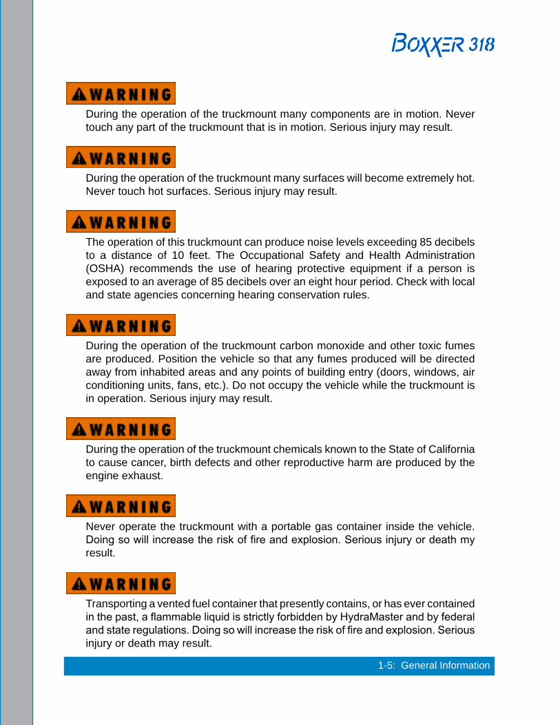
During the operation of the truckmount many components are in motion. Never touch any part of the truckmount that is in motion. Serious injury may result.
During the operation of the truckmount many surfaces will become extremely hot. Never touch hot surfaces. Serious injury may result.
The operation of this truckmount can produce noise levels exceeding 85 decibels to a distance of 10 feet. The Occupational Safety and Health Administration (OSHA) recommends the use of hearing protective equipment if a person is exposed to an average of 85 decibels over an eight hour period. Check with local and state agencies concerning hearing conservation rules.
During the operation of the truckmount carbon monoxide and other toxic fumes are produced. Position the vehicle so that any fumes produced will be directed away from inhabited areas and any points of building entry (doors, windows, air conditioning units, fans, etc.). Do not occupy the vehicle while the truckmount is in operation. Serious injury may result.
During the operation of the truckmount chemicals known to the State of California to cause cancer, birth defects and other reproductive harm are produced by the engine exhaust.
Never operate the truckmount with a portable gas container inside the vehicle. Doing so will increase the risk of fire and explosion. Serious injury or death my result.
Transporting a vented fuel container that presently contains, or has ever contained in the past, a flammable liquid is strictly forbidden by HydraMaster and by federal and state regulations. Doing so will increase the risk of fire and explosion. Serious injury or death may result.

General Information: 1-6
Never smoke in or around the truckmount. Doing so will increase the risk of fire and explosion. Serious injury or death may result.
During the operation of the truckmount the exhaust system will become extremely hot. Keep all flammable materials away from the truckmount exhaust system. Failure to do so will increase the risk of fire and explosion. Serious property damage may result.
Never operate the truckmount when the vehicle is tilted more than 10 degrees in any direction. Doing so will result in improper lubrication of the internal components, and will increase the risk serious component or engine damage.
Never perform cleaning operations when the truckmount engine is running at the IDLE throttle position. Failure to do so will increase the risk of serious component or engine damage.
Never operate the truckmount with the vehicle doors closed. Doing so results in extremely high temperatures inside the vehicle and will lead to serious component or engine damage.
Never use concentrated acids or solvents (including d-limonene) in the truckmount water system or chemical system. Use of these products will cause serious component damage.
Never operate the truckmount with a water hardness reading measuring 3.0 grains per gallon or higher. Using reading than 3.0 grains per gallon will cause scale to build up inside the truckmount water system. Scale build up causes serious component damage. Test all water prior to use and use water softening equipment if necessary.
1-7: General Information
Never allow water to freeze inside the truckmount. Serious component damage will occur. Perform all freeze guarding procedures outlined in the digital Owner’s Manual.
Many vehicles have critical components mounted directly below the floor that can easily be damaged. Before drilling holes in the floor of the vehicle, inspect the underside of the vehicle for critical components. Failure to do so may result in damage to the vehicle.
During the operation of this equipment, surfaces will become hot. Do not allow components such as hoses to touch hot surfaces. Failure to heed this warning can result in equipment damage which is not covered by warranty.

General Information: 1-8
RESPONSIBILITIES
The Purchaser’s ResponsibilitiesPrior to purchasing a van, ensure that the payload is suitable for all of the equipment that will be installed and transported. This includes and is not limited to: the truckmount, recovery tanks, fresh water tanks and on-board water, hose reels, hoses, cleaning tools, chemicals, drying equipment, etc. Payload capacity information is available through the auto dealer, the manufacturer’s web site, and is also located on the door pillar of the driver’s side door.
Purchase a heavy duty Group 24 (550 CCA or better) battery for this truckmount. This is normally available from the installation dealer.
Prior to dropping your van off at the distributor for the truckmount to be installed, have a spray-on bed liner applied to the floor such as Rhino Lining® or Line-X®.
Prior to operating the truckmount read this manual in its entirety and familiarize yourself with the information contained here. Special attention should be paid to all cautions and warnings.
The distributor is responsible for the correct installation of the truckmount. The distributor is also responsible to train you in the correct and proper operation and maintenance of the truckmount.
Any modification of the truckmount may void the warranty.
The Distributor’s Responsibility
Acceptance of ShipmentBefore accepting the truckmount, check the following:• The truckmount should be free from any damage during shipping. Do not sign the
delivery receipt until you have closely inspected the truckmount and noted any damage on the delivery receipt. Hidden damage may be present even if the box looks okay. It is recommended that the box be opened before signing for the shipment.
• Check the packing list and verify that all items are accounted for.

1-9: General Information
Installation Responsibilities• Ensure proper payload capacity. It is the distributor’s responsibility to verify that the
equipment package does not exceed the vehicle capacity.• Ensure installation of a safe fuel tap system and through-floor fittings as provided by
HydraMaster.• Proper placement of the truckmount, recovery tank, fresh water tank, and accessories
in the vehicle and securing them with bolts and back up plates. The distributor should verify that the owner is in agreement with the layout.
• Ensure proper connection of the fuel lines.• Ensure proper connection and installation of the battery. Verify that the battery is in
accordance with HydraMaster’s recommendation.• Check the pump, vacuum blower and engine oil levels prior to starting the truckmount.• Start and run the truckmount and check that all systems function properly.• Test all hoses, wands, etc. for correct operation.• Ensure timely return of the document package.
TrainingThe distributor should provide a thorough review of the operation manual with the purchaser along with instruction and familiarization in:
• How all the truckmount’s systems function.• All safety precautions and their importance.• How to correctly start and shut down the truckmount.• How to correctly clean with the truckmount.• Where and how often to check and change component oil levels.• Freezing damage and how to avoid it. This includes explaining proper freeze guarding
procedures.• How to do basic troubleshooting of the truckmount.• Hard water damage and how to avoid it. This includes how to determine if hard water
exists in your area and the installation and use of water softening systems.• The truckmount’s warranty and warranty procedures.

General Information: 1-10
SYSTEM CONCEPTThe system utilizes an internal combustion engine to provide the power necessary to turn both a vacuum pump and a high pressure water pump.
The heat of the engine and blower exhausts is transferred to the high pressure water in the finned tube heat exchanger of the system.
Finally, the chemical is injected into the pressurized water stream and the heated solution is delivered to the cleaning tool. The solution is recovered by the vacuum generated by the vacuum pump This solution is collected in the recovery tank for proper disposal.
1-11: General Information
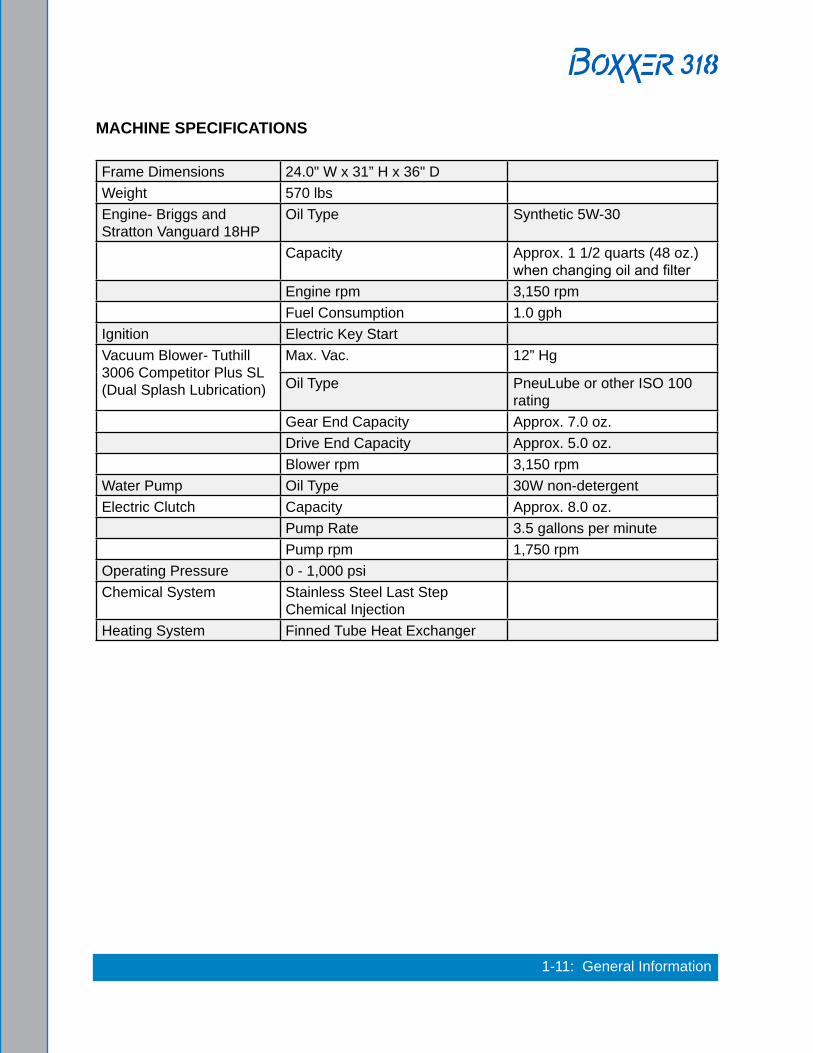
MACHINE SPECIFICATIONS
Frame Dimensions 24.0" W x 31” H x 36" DWeight 570 lbsEngine- Briggs and Stratton Vanguard 18HP
Oil Type Synthetic 5W-30
Capacity Approx. 1 1/2 quarts (48 oz.) when changing oil and filter
Engine rpm 3,150 rpmFuel Consumption 1.0 gph
Ignition Electric Key StartVacuum Blower- Tuthill 3006 Competitor Plus SL (Dual Splash Lubrication)
Max. Vac. 12” Hg
Oil Type PneuLube or other ISO 100 rating
Gear End Capacity Approx. 7.0 oz.Drive End Capacity Approx. 5.0 oz.Blower rpm 3,150 rpm
Water Pump Oil Type 30W non-detergentElectric Clutch Capacity Approx. 8.0 oz.
Pump Rate 3.5 gallons per minutePump rpm 1,750 rpm
Operating Pressure 0 - 1,000 psiChemical System Stainless Steel Last Step
Chemical InjectionHeating System Finned Tube Heat Exchanger

General Information: 1-12
Standard Equipment High Pressure Hose 1/4" High Temperature Lined/Vinyl Cover - 100 ft.
Vacuum Hose 2" Vacuum Hose- 100 ft.1-1/2" Wand Whip Line- 10 ft.
Recovery Tank 65 gallon MaxAir Universal Tank
Cleaning Wand Stainless Steel S-bendReplaceable GripRebuildable Solution Valve
Chemical Jug 5 gallonBattery BoxVan DecalVan Installation KitOwner’s Manual (on CD)Owner’s Guide (paper copy)
Optional Equipment Recovery Tank 100 Gallon MaxAir Universal Tank - Single Port
Fresh Water Tank 70 Gallon Rotomolded Tank85 Gallon Rotomolded Tank
Automatic Pump Out (APO) Dura-Flow APO

1-13: General Information
HIGH ALTITUDE OPERATION Elevation plays a key role in how the truckmount will operate. Operation at high altitude (above 5,000 ft.) may require a high-altitude carburetor jet. Use of this jet at high altitude will improve power, reduce fuel consumption and help reduce excessive carbon build-up in the exhaust and heat exchanger systems.
Contact the local Briggs and Stratton dealer or HydraMaster to obtain the proper jet size. Your local Briggs and Stratton dealer can be located at http://www.briggsandstratton.com/us/en/support/dealerlocator .
LOCAL WATER PRECAUTIONSThe quality of water varies greatly. Many areas have an excess of minerals in the water which results in what is commonly called “hard water.” These minerals tend to adhere to the insides of heater coils and other parts of the machines causing damage and a loss of cleaning effectiveness. This influences the reliability and efficiency of equipment in direct proportion to the level of hardness.
Hard Water AdvisoryHydraMaster recognizes that any hard water deposits which might occur within the water system of our truckmounts is a serious problem. The precision technology of truckmount heat exchanger systems is intolerant of any foreign material. Hard water deposits will ultimately decrease the performance of the system and are expected to seriously lower the reliability of the machine.
To validate a machine’s warranty, HydraMaster requires that all machines operating in designated “Hard Water Areas” (3.0 grains or more per gallon) be fitted with a water softening system, or a properly installed magnetic-type descaler must be used and maintained. Periodic descaling or acid-rinsing alone is not adequate in these areas. HydraMaster does not recommend any particular type or brand; however, the relative effectiveness of some types of magnetic descalers or softeners may require additional periodic use of descaling agents.
HydraMaster also recommends, in the strongest possible terms, that machines in all areas be fitted with a water softening system for improved operation and reliability.
Failure to take appropriate measures to prevent scale build up can result in system failure and loss of warranty on affected parts.

General Information: 1-14
Hard Water Area MapThe hard water map, shown in Figure 1-1, defines hard water areas in the continental United States which compromise fluid related components such as hoses, fittings, heaters, pumps, valves and water-cooled engines. For other countries, hard water area maps can be obtained from geological societies.
Figure 1-1. Hard Water Map of Mainland United States
The map shown in Figure 1-1 is provided for general reference only. Water hardness in your geographical location should be confirmed by testing.

1-15: General Information
Water SoftenerCleaning efficiency and equipment life is increased, chemical use decreased, and the appearance of cleaned carpets enhanced when water softeners are incorporated in hard water areas. HydraMaster strongly urges the use of water softener units with the Boxxer 318 in areas exceeding 3.0 grains per gallon.
Failure to use a water softener in these areas will invalidate the machine’s warranty. Referring to the hard water area map shown Figure 1-1, determine the quality of water in your area and take immediate action if the water hardness exceeds 3.0 grains per gallon.
The relatively low cost of a water softener service is more than made up for by an increased life of machine parts, reduced chemical costs and continued cleaning efficiency. The water softener will also increase the effectiveness of the cleaning chemicals, therefore less chemical will be needed. Contact a water softener distributor in your area for information on the rental of a simple water treatment unit to carry in your truck. Be sure to charge the water softener in accordance with the capability of the softener.
For example: If the softener will treat 900 gallons of water and the machine uses an average of 30 gallons/hour, for an average of 5 hours a day, this equals 150 gallons per day). In 6 days the machine would use 900 gallons of water. Therefore, the softener would need to be charged every 6 working days for maximum softening.

General Information: 1-16
Waste Water Disposal AdvisoryThere are laws in most communities prohibiting the dumping of recovered “gray” water from carpet cleaning in any place but a sanitary treatment system.
The cleaning rinse water, recovered into your unit’s vacuum tank, contains materials such as detergents, and must be safely processed before entering streams, rivers and reservoirs.
In most cases, an acceptable method of waste water disposal is to discharge into a municipal sewage treatment system after first filtering out solid material such as carpet fiber. Access to the sanitary system can be obtained through a toilet, laundry drain, RV dump, etc. Permission should first be obtained from any concerned party or agency.
One disposal method which usually complies with the law is to accumulate the waste water and haul it to an appropriate dump site. Another solution to the disposal problem is to equip your Boxxer 318 with an Automatic Pump-Out System (APO). These systems are designed to remove waste water from the extractor’s recovery system and actively pump the water through hoses to a suitable disposal drain.
HydraMaster makes an APO System which can be ordered with new equipment or installed later.
When properly configured, the systems will continuously monitor the level of waste water and pump it out simultaneously with the cleaning operation. The hidden benefit of this process is that the technician does not have to stop his/her cleaning to empty the recovery tank.
IN ACCORDANCE WITH EPA, STATE AND LOCAL LAWS, DO NOT DISPOSE OF WASTE WATER INTO GUTTERS, STORM DRAINS, STREAMS, RESERVOIRS, ETC.
The penalties for non-compliance can be serious. Always check local laws and regulations to be sure you are in compliance.
2-1: Chemicals and Cleaning
2 - Cleaning and ChemicalsYour HydraMaster truckmount has been engineered using the latest and most sophisticated technology available to produce the finest carpet cleaning results possible. Despite this, it remains only a tool of the carpet cleaning trade and can produce only as a good a job as the person operating it.
HydraMaster strongly recommends attending an Institute of Inspection, Cleaning and Restoration Certification (IICRC) approved school as soon as possible and to always follow the IICRC guidelines when cleaning.
This section describes the carpet cleaning procedure in the following areas:
� Precautions � Preparing the Carpet for Extraction � Rinse and Recover � Overwetting � Streaking � Cleaning Tool Tips
PRECAUTIONSThe use of some chemicals (such as concentrated acids and/or solvents) in your truckmount can seriously damage the internal plumbing and high pressure pump.
HydraMaster strongly recommends purchasing a water softener to prevent the buildup of scale and hard water deposits in your truckmount.
HydraMaster recommends only the use of chemicals containing rust and corrosion inhibitors and water softening agents to prevent chemical buildup which may lead to component failure and warranty invalidation.
Increased demand for a neutralizing rinse results in the need for special care when using these acid based chemicals in your truckmount The negative side of these products is the corrosive effects the acid can have on metals, including fittings, pumps, heat exchangers, etc.
HydraMaster’s ClearWater Rinse™ has been formulated to protect vital components. HydraMaster will not warranty parts that have been damaged from using acid products that have obviously caused failures.

Chemicals and Cleaning: 2-2
PREPARING THE CARPET FOR EXTRACTION
Pre-Vacuum the Carpet Whether you instruct the customer to pre-vacuum or you offer it as part of your service, proper vacuuming will make your job easier with superior end results. The more time spent removing loose particulate soil, the easier it will be to remove the oily soil stuck to the fibers.
Pretreat the CarpetThis process of applying traffic lane type chemicals to the carpet (whether by sprayer or rotary scrubber) is essential prior to extraction with your truckmount.
By applying cleaning agents to the carpet and letting them dwell 10-20 minutes prior to rinsing, you allow the product to dissolve and emulsify the oily, sticky binders holding the soil to the fiber. This will allow more soil to be removed in one or two cleaning passes and help prevent over-wetting.
Remember the solution coming out of your cleaning tool is only in contact with the carpet fiber for a few seconds. Relying on the rinse detergent to do the majority of the cleaning will result in overly long dry times and excess detergent residue left in the carpet.
HydraMaster recommends the use of our pre-sprays: Fastbreak™ for residential carpet and Blitz™ for commercial carpet needs.
RINSE AND RECOVERWhether you are using a wand or a rotary extraction tool, you should clean an area approximately 3 ft. x 3 ft. with the solution valve open then immediately go over that area with vacuum only to remove any excess moisture.
Olefin fiber is becoming more popular, particularly in commercial installations. The process mentioned above can leave excessive residual moisture because olefin fibers will not absorb any of the cleaning solution. You must only apply solution during the backward stroke of the wand so it can be immediately captured by the vacuum head. RX-20® users should follow each pass with a dry pass. Failure to follow this procedure will cause solution to flow to the back of the carpet along with some of the soil. This, along with any soil imbedded in the backing, will be wicked to the surface of the fibers as the carpet dries.
HydraMaster recommends the following rinse aids: Alkaline - Hydra-Dri Powder™ or Hydra-CleanLiquid™. Acid - Clear Water Rinse™.

2-3: Chemicals and Cleaning
For more information about HydraMaster’s complete chemical product line, visit this webpage: http://hydramaster.com/Products/Chemicals.aspx
OVERWETTINGOverwetting is an annoyance to all concerned. Extended drying times will leave the customer with a negative impression of both the cleaning company and the process used.
There are several factors that will cause over-wetting:1. Too few vacuum strokes.2. Clogged vacuum blower filter or Recovery Tank lid not sealing properly.3. Recovery Tank drain valve left partially open.4. Obstructed, cut or kinked vacuum hoses.5. Obstructed vacuum hoses while cleaning a heavily foam-saturated carpet (it is
recommended to use a crystal type defoamer distributed evenly over the carpet).
STREAKINGStreaks in the carpet can appear in both clean or dirty areas and normally appear in heavily soiled, light colored carpets.
Possible reasons of streaking may include:1. Clogged or improperly angled spray nozzles.2. Spray nozzles that overlap, concentrating the solution.3. A partially clogged vacuum head.4. Inconsistent solution temperature.

Chemicals and Cleaning: 2-4
CLEANING TOOL TIPS
WandsWith a wand, keep cleaning strokes short, front to back, and run a “dry pass”.
After pulling the wand for a strip of 3 or 4 ft long with the solution trigger activated, go back up to the top of the stroke, and make a “dry “ pass [i.e. no solution flowing]. This gives the wand a second chance to pick up the solution on the carpet.
If you do not run a dry pass, the carpet can take longer to dry, and, possibly, the pad under the carpet can become saturated.
Be aware of the carpet seams; try to use strokes that are parallel with the seam. Avoid pulling the wand across the seam. Every stroke can peel the seam connection and pull the carpet off the floor.
Also, tilt the wand handle down [head up] to move the tool forward, and away from you, on the carpet. This means less pull on the carpet and less work for you.

2-5: Chemicals and Cleaning

Chemicals and Cleaning: 2-6

2-7: Chemicals and Cleaning
RX-20® Tool Before turning on the RX-20, adjust the handle; it should rest right below or even with the bottom of your pants’ front pockets, with the tool resting flat on the floor. Take your time in adjusting the tool’s height; make sure the head of the tool is flat with the floor while you are holding the handle. Relax your posture; the more difficult it is to hold the tool’s head flat on the floor surface, the more quickly you will tire.
While the tool is running, control the left and right movements of the tool by tilting the head to the front and back, and lifting the handles up and pushing the handles down. The tool can be driven to the forward and backward by tilting the head of the unit to the left and right. The head must be turning to use the self driving feature of the tool, and only requires a slight bit of pressure to handles to get the head to move the tool across the floor.
As with the wand, drying times will be improved if you run a dry pass between wet passes. Hold down the solution trigger and move the unit left or right across the floor 3 or 4 ft, then immediately back across the same pass, without the solution flowing, to make the dry pass. Make the next pass half-overlapping the previous pass. Use the RX-20 in very heavily trafficked areas or if it has been a long time since the carpet has been cleaned. Beware of the seam edges of carpets and transition edges between floor surfaces. Use extreme caution when cleaning these areas.
Sometimes it is necessary to use an edge tool or wand to run the perimeter of the room on in difficult-to-reach areas where the circular head of the rotary units will not reach.
The 5 vacuum heads and 3 jets rotate at 130 rpm, creating
650 complete cleaning passes per minute.
For Truckmount or Portable Carpet Cleaning Systems
• Aggressive restorative extractor tool for carpet, hard surface and bonnet cleaning
• Labor-saving, ergonomic design• Superior agitation for cleaning
stains, heavily soiled and matted carpet
• Durable construction for long life
• Reduces fatigue of the operator
Chemicals and Cleaning: 2-8
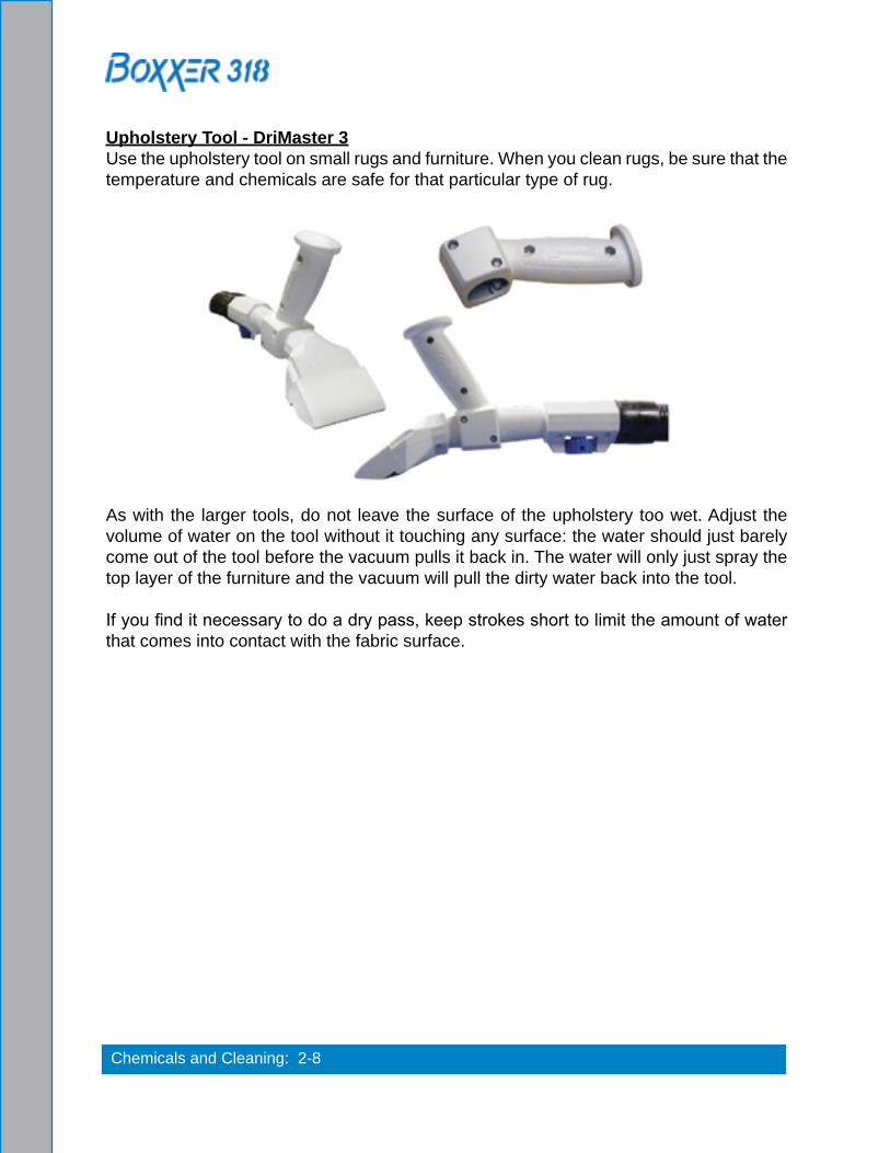
Upholstery Tool - DriMaster 3Use the upholstery tool on small rugs and furniture. When you clean rugs, be sure that the temperature and chemicals are safe for that particular type of rug.
As with the larger tools, do not leave the surface of the upholstery too wet. Adjust the volume of water on the tool without it touching any surface: the water should just barely come out of the tool before the vacuum pulls it back in. The water will only just spray the top layer of the furniture and the vacuum will pull the dirty water back into the tool.
If you find it necessary to do a dry pass, keep strokes short to limit the amount of water that comes into contact with the fabric surface.

3-1: Operating Instructions
3 - Operating InstructionsSTART-UP PROCEDURE1. Perform all daily and periodic maintenance as specified in Section 4 of this Owner’s
Manual.2. Connect a garden hose to supply water to the truckmount. If used, turn the “PUMP-IN”
switch to the “ON” position (see Figure 3-1).
The water box must be full prior to starting the truckmount.
3. Connect the cleaning tool to the length of hose required to perform the cleaning job.
4. Turn the key to “ON”. Pull the choke and start the truckmount with the throttle cable fully depressed (“IDLE” position - see Figure 3-1).
5. After the engine starts, push the choke in and allow the truckmount to run in “IDLE” for 2 - 3 minutes to warm up.
6. Pull the throttle cable to full extension and twist the handle clockwise to lock.
Figure 3-1. Location of Throttle, Choke and Pump-In/Pump Clutch Switch
Pump-In/Pump Clutch Switch
Choke
Throttle
Ignition and Key

Operating Instructions: 3-2Figure 3-2. Front View of Boxxer 318 Console
Temperature Knob
Optional Auto Pump-Out Switch
Chemical Selection Valve
Chemical Metering Control Knob
Vacuum Gauge
Pressure Gauge
Blower Lube Port

3-3: Operating Instructions
7. Press the “PUMP CONTROL” switch to engage the pump clutch for carpet cleaning or upholstery cleaning as follows: a. Switch to the “HP Only” if connected to a fresh water supply from a building. b. Switch to the “HP ON & Pump-In ON” if connected to a fresh water tank.
8. Set the temperature to the desired level on the “TEMPERATURE” knob.9. If used, turn the “AUTO PUMP-OUT” switch to the “ON” position.
10. Adjust the “PRESSURE REGULATOR”, located on the left hand side of the machine (see Figure 3-3), to the desired cleaning pressure level.
Suggested Settings: Carpet Cleaning: 300 - 400 psi Hard Surface Cleaning: 1,000 psi or as indicated on the tool
11. Turn the “CHEMICAL SELECTION VALVE” to the “PRIME” position to purge any air from the system.a. With the truckmount running at full throttle, block off the vacuum intake to the
recovery tank. The vacuum gauge should read 12”-14” Hg. This will assist in priming the chemical system.
b. Allow the chemical to flow through the chemical meter at full flow for 30 seconds.
c. Turn the “CHEMICAL SELECTION VALVE” to “ON.” The restriction can now be removed from the vacuum inlet.
d. While spraying solution from the cleaning tool adjust the chemical flow by turning the “CHEMICAL METERING CONTROL KNOB”.
12. Begin cleaning.
TBD
Pressure Regulator
Figure 3-3. Side View of Boxxer 318 Console

Operating Instructions: 3-4
Never perform cleaning operations when the truckmount engine is running at the IDLE throttle position. Failure to follow this caution will increase the risk of serious component or engine damage.
WATER EXTRACTION PROCEDURETo perform water extraction, set the “PUMP CONTROL” switch to the flood extraction position. This will disengage the pump clutch, allowing for the machine to run without fresh water connected to the machine.
SHUT-DOWN PROCEDURE1. Flush clean water through the chemical system for 10 seconds. Turn the “CHEMICAL
SELECTION VALVE” to “OFF.”2. Cool the truckmount down by turning the “TEMPERATURE CONTROL” dial to the
lowest position (counter-clockwise). Spray the cleaning wand into the vacuum hose for 3 - 5 minutes. The chemical is now flushed from the truckmount, hoses and cleaning tool.
3. Remove the vacuum hose.4. Lubricate the blower to prevent it from rusting internally.
a. Allow the unit to run for a few minutes with the vacuum hose disconnected in order to remove moisture from the blower.
b. Cap off the inlet(s) to the vacuum tank.c. Spray a HydraMaster-recommended spray lubricant into the “BLOWER LUBE
PORT” for about 5 to 7 seconds while the unit is running (see Figure 3-2).d. Allow machine to run additional 2 to 5 minutes under load to flush off lubricant.e. Uncap the inlet(s) and run the unit for another minute to allow the blower to cool
down.5. If freeze guarding is necessary perform the procedure at this time. See Section 4 of
the Freeze Guarding section in the Owner’s Manual.6. Return the engine throttle to the “IDLE” position.7. Turn the key to “OFF.”8. Drain the water box using the valve.9. Drain the vacuum tank in an appropriate location.
In accordance with the EPA, state and local laws, do not dispose of water into gutters, storm drains, streams, reservoirs, etc.
10. Perform daily maintenance as specified in Section 4 of this Owner’s Manual.
4-1: Machine Maintenance
4 - Machine MaintenanceTo avoid costly repairs and down-time, it is imperative to develop and practice good maintenance procedures from the beginning. These procedures fall into daily, weekly, monthly and quarterly increments, and are outlined in this section. All recommended maintenance must be performed by competent service personnel.
This section covers: � Operational Maintenance � Overall Machine Maintenance � High Pressure Pump Maintenance � Vacuum System Maintenance � Descaling Procedure (Required) � Freeze Guarding � Tensioning the Pump Drive Belt
Record the date and machine hours on the maintenance log provided for your convenience in the Owner’s Guide. Records of maintenance must be kept and copies may be required to be furnished to HydraMaster before the warranty is honored. It is recommended that you affix a copy of the log on the vehicle door near your unit for convenience and to serve as a maintenance reminder.

Machine Maintenance: 4-2
OPERATIONAL MAINTENANCE
Daily Maintenance• Check the engine oil level. Add oil if needed.• Check the high pressure pump oil. Add oil if needed.• Inspect and clean the recovery tank filters.• Inspect and clean the orifices and filters.• Inspect and clean the garden hose screen.• Inspect the truckmount for water and oil leaks, loose electrical connections, etc. and
repair as needed.• Lubricate the blower lube port with HydraMaster-recommended spray lubricant.
Weekly Maintenance• Inspect the recovery tank filters for tears, holes, etc. Repair or replace as needed.• Inspect the vacuum relief valve. Clean and lubricate as necessary.• Clean the recovery tank thoroughly with pressure washer.• Check the oil level in the blower. Add oil if needed.• Check the pump drive belt for wear and proper tension. Tighten as needed.• Check all the hoses and wiring for wear and chafing. Secure as needed.• Flush the water and chemical systems with solution of equal parts white vinegar and
water.• Check all the nuts and bolts. Tighten as needed.• One time change of the high pressure pump oil after 50 hours of operation. (Every 500
hours thereafter.)• One time change of the engine oil after 8 hours of operation.• Change the engine oil every 50 hours. (Every 25 hours if operating in high ambient
temperatures or heavy use conditions.) Change oil filter every oil change.
Monthly Maintenance• Check the engine air filter. Clean or replace as necessary.• Check the water level in battery. Fill as needed.• Clean the battery terminals as needed.• Change the blower oil after first 100 hours of use.
Quarterly Maintenance• Check the fuel lines. Repair or replace as needed.• Clean and gap the spark plugs to 0.030”. Replace if excessive carbon buildup is visible.• Change the fuel filter.• Change pump drive belt.
100 Hours• Replace spark plugs

4-3: Machine Maintenance
250 Hours• Check coupler element (rubber insert) for cracks or wear. Replace as necessary.
500 Hours• Change the blower oil.• Change the high pressure pump oil.• Check the engine valve clearance (intake and exhaust 0.004” - 0.006”)• Change the fuel filter.• Check coupler element (rubber insert) for cracks or wear. Replace as necessary.
1000 Hours• Change air filters.• Check plug wires. Replace as necessary.• Check carburetor. Clean or replace as necessary.• Clean the heat exchanger core.• Replace coupler element (rubber insert) for cracks or wear.
Refer to the Interval Hours Maintenance chart in the Owner’s Guide.

Machine Maintenance: 4-4
HIGH PRESSURE PUMP MAINTENANCE
DailyCheck the oil level and the condition of the oil. The oil level should be up to the center of the sight glass on the rear of the pump or between the “MIN” and “MAX” lines on the dipstick. The dipstick may be found by removing the oil cap.
PeriodicallyChange the oil after the initial 50 hours of operation and every 500 hours after that. It may be necessary to replace the pump seals and check valves at 500 hours if the truckmount has been running in high ambient temperatures.
If the oil becomes discolored or contaminated one of the oil seals may be damaged. Do not operate the pump if the crankcase oil has become contaminated. Do not rotate the drive shaft without oil in the crankcase reservoir.
The pump should never be run dry. Running the pump dry will cause premature wear on the seals, packing and plungers. Running the pump dry for a prolonged period of time may cause damage that cannot be repaired and voids warranty.
Do not run the pump with frozen water in the manifold. If there is a risk of freezing, freeze guard the truckmount. See page 4-10 of this section for freeze guarding information.
ServiceThe next few pages explain how to disassemble and inspect all user serviceable parts of the pump.
Do not disassemble the pump unless you are a skilled mechanic. For assistance, contact your distributor.

4-5: Machine Maintenance
Valve Maintenance (See Figure 4-1)1. Using a 22-mm wrench or socket, remove all six valve caps on the manifold of the
pump.2. Examine each valve cap O-ring for cuts or distortions and replace if worn.3. Using needle nose pliers, remove the suction and delivery check valves. The valve
assembly usually stays together when removing. If the valve comes apart, use the needle nose pliers or reverse pliers to remove the remaining parts.
4. Inspect each suction and delivery check valve assembly for wear and pitting, and replace if necessary. The valve assembly consists of the plastic cage, spring, valve seat, poppet and O-ring. One valve kit is needed for complete valve change of one pump.
Figure 4-1. Servicing the Valves

Machine Maintenance: 4-6
5. Replace old valves with new valves by placing the assembly in the valve chamber. Press down firmly on the top of the valve assembly.
6. Replace valve caps by applying LOCTITE® 243 to valve cap and torque to 33 ft-lbs.
Removing and Replacing Pump Manifold1. Remove the manifold of the pump by taking a 5-mm Allen head wrench and removing
the eight head bolts.2. With the pump firmly secured, take a medium sized flat head screwdriver and apply
pressure to the manifold by prying between the crankcase and manifold. Work around from all sides of the manifold evenly until it comes off of the pistons. Keep the manifold properly aligned with the pistons to prevent damage to the seals and pistons.
3. When replacing the manifold, turn the crankshaft of pump until the top of the pistons are closely aligned. Lubricate the pistons and cylinders with grease and evenly press the manifold toward crankcase until flush.
Seals and V-Packing Maintenance1. Remove the manifold as previously described. It is possible that the seal and brass
retainer ring assembly will stay on the piston or will remain in the manifold when removing it.
2. Carefully remove the brass retainer ring/seal stack. Remove the low-pressure seal using needle nose pliers. Discard the old seal.
3. Remove the outer O-ring by taking a small flat head screwdriver and working it under the O-ring. Simply roll off the old O-ring and discard.
4. The old V-packing stack can be taken apart by hand and discarded.
Seals and V-Packing Reassembly1. Generously lubricate parts with grease when reassembling. Examine all brass
components for any damage or water residue build-up. Clean or replace as needed.
2. Insert a new low pressure seal by working it in by hand.3. Install the new outer O-ring by simply starting on one side and working it into the
groove.4. Stack the new V-packing in the correct order and firmly press the assembly into the
manifold.5. Install a new low pressure oil seal by laying the seal into the opening and evenly
pressing it into place.6. Re-install the manifold onto the pump as previously described.

4-7: Machine Maintenance
Plunger Maintenance1. Remove the manifold as previously described. Remove the packing retainers if they
remain on the pistons after removing the manifold.2. Remove the nut and washer on the end of the piston using a 13-mm wrench or
socket.3. Slide the ceramic plunger and the remaining washer from the piston guide. Inspect
the ceramic piston, O-ring and washers for wear. Replace if necessary.
Plunger Re-assembly1. Generously grease the piston guide. Replace the O-ring making sure it does not
twist or roll.2. Slide the lower washer and ceramic bushing onto the piston guide.3. Place a small amount of LOCTITE 243™ on the piston guide threads. Replace the
old washer and thread the nut onto the piston guide. Torque to 4.5 ft-lbs.
Servicing the Crankcase1. While the manifold and plungers are removed, rotate the crankshaft by hand. Closely
examine the crankcase oil seals for drying, cracking or leaking.2. Consult the local HydraMaster distributor if crankcase servicing is necessary.

Machine Maintenance: 4-8
VACUUM SYSTEM MAINTENANCEThe vacuum pump in this machine is commonly referred to as a “rotary positive displacement blower” or “blower” for short. The performance and life of the truckmount is greatly dependent on the care and proper maintenance it receives. Review the blower’s owner’s manual, which has been included, for a better understanding of this piece of machinery.
To protect the blower from overloading and damaging itself, a vacuum relief system is installed on the recovery tank. When the recovery tank inlet is completely sealed off, a maximum of 12” Hg will be attained.
Solid objects entering the blower will cause serious damage to the internal components of the blower. Extreme caution should be used when the truckmount is being run for test purposes with the inlet to the blower open to the atmosphere.
Foam passing through the blower can lead to serious problems with the truckmount. It is important to keep the recovery tank free of foam. The tank is protected from overflowing by a float kill switch; however, this switch is not activated by foam.
DailyAt the end of each day the internal components of the blower need to be lubricated. This helps to prevent rust deposits and prolongs the life of the truckmount.
Lubricate the blower to prevent it from rusting internally by:1. Allowing the unit to run for a few minutes with the vacuum hose disconnected in
order to remove moisture from the blower.2. Capping off the inlet(s) to the recovery tank.3. Spraying a HydraMaster-recommended spray lubricant into the “BLOWER LUBE
PORT” for about 5 to 7 seconds while the unit is running.4. Uncapping the inlet(s) and run the unit for another minute to allow the blower to cool
down.
PeriodicallyChange the oil in both ends of the blower after the initial 100 hours of use. Change the oil each 500 hours of use thereafter.

4-9: Machine Maintenance
DESCALING PROCEDURE (REQUIRED)Scale deposits on the interior of the heating system can cause a noticeable loss in heating performance. Deposits of this kind result from hard water deposits. The frequency with which descaling procedures are required will vary. If the area has particularly hard water, you may have to descale often.
To descale the system, add an appropriate descaler chemical to the water box. Circulate it through the system. Let it stand. Flush and repeat as necessary. Clean all screens and strainers, and check them frequently following descaling.
If using TM DeScaler™ through the flow meter, make sure to run clean water through the flow meter after this procedure.
To descale using the recirculation kit (P/N 000-078-058), start with an empty water box.
1. Fill a third of the water box with TM DeScaler. Follow the recommendations on the TM DeScaler label for proportions. Verify that the float is not lying horizontal, but floats below.
2. Attach the recirculation fitting provided in the kit to the garden hose quick connect (see Figure 4-2) and this combination to the front of the truckmount.
3. Attach one section of the solution hose to the outgoing solution fitting on the front of the truckmount and the other end to the garden hose and recirculation fitting combination that is attached to the front of the truckmount. Additional hoses may be attached inline if descaling of hoses is needed.
4. Start the truckmount and allow it to run for 3 - 5 minutes. Do not leave the TM DeScaler solution in the system. Flush the system with clean water and turn the truckmount OFF.
Figure 4-2. Recirculation Fitting
000-078-058

Machine Maintenance: 4-10
FREEZE GUARDINGTo avoid permanent damage to the truckmount, it is imperative to follow the freeze guard procedure whenever the possibility of freezing temperatures exists.
When disposing of antifreeze follow local laws and regulations. Do not discard into storm sewers, septic systems, or onto the ground.
Antifreeze is harmful or fatal if swallowed. Do not store in open or unlabeled containers. Keep out of reach of children and animals.
Freeze Guard Procedure1. With the truckmount turned off and the incoming water line disconnected, open
the water box drain valve on the front of the truckmount. Allow the system to fully drain.
2. Add 2 gallons of 50/50 antifreeze and water mix to the water box.3. Attach a section of solution hose to the outgoing solution fitting on the front of the
machine. Attach the opposite end to the recirculation fitting. (If more sections of hose are to be freeze guarded attach those inline.)
4. Start the truckmount and allow it to run for 2 to 3 minutes. This will distribute antifreeze solution throughout the truckmount.
5. Remove the chemical feed line from the chemical jug. Turn the selector valve to “PRIME.” This will vacuum the chemical remaining in the lines to the recovery tank.
If using the recirculation kit, skip ahead to step 7.
6. Remove the quick connect from the truckmount.7. Spray the antifreeze and water mix out of the truckmount and into a container to
reclaim the solution. Run the truckmount until there is no more solution coming from the truckmount.
8. The truckmount is now freeze guarded. Remember to flush antifreeze from the system prior to carpet cleaning. See the following procedure.

4-11: Machine Maintenance
The reclaimed antifreeze solution may be used three times before being discarded.
To freeze guard the hoses and wand perform step 7 with the items to be freeze guarded attached.
Recovering Antifreeze for Re-Use1. Attach all hoses and wands which have been freeze guarded to the truckmount.2. Attach the incoming water source to the front of the truckmount.3. Start the truckmount.4. Spray the solution through the hoses and wands into a sealable container until all
signs of antifreeze are gone.
Freeze Protection of the Pump-In System1. Drain the fresh water tank.2. Remove the garden hose adapter from the pump-in pump hose and position the
hose so it is pointing outside the van.3. Turn on the pump-in pump and run for 1-2 minutes until all the water is purged from
the hose.
The next time the truckmount is used it may take a few minutes before the water box begins to fill.

Machine Maintenance: 4-12
TENSIONING THE PUMP DRIVE BELT1. Remove the Boxxer 318 grill to gain access to the idler pulley.2. Loosen but do not remove the 2 ¼” long bolt (P/N 000-143-041) on the idler pulley.
See Section 9 in the Owner’s Manual.3. Remove the right cover of the machine to gain access to the tensioning screw.4. Adjust the tension of the belt by turning the 4” long screw (P/N 000-143-376). 5. After the proper belt tension is achieved, tighten the ½” bolt on the idler pulley.
Ensure there is no contact between idler assembly (including belt) and no other part of the truckmount. Contact between the parts could result in damage to the truckmount.
6. Replace the right cover and grill.

5-1: Water and Chemical System
5 - Water and Chemical System
This section describes the water and chemical systems in the following areas:
� Water and Chemical Flow Operation � Water and Chemical Flow Diagrams
WATER AND CHEMICAL FLOW OPERATIONFresh water is brought through the front of the truckmount into the water box. The level of water in the box is maintained by the use of a float valve. The water is then gravity fed to the pump where it is pressurized.
Next, the pressurized water enters the by-pass valve. This valve allows manual adjustment of the pressure level. When the valve at the wand is closed, nearly all of the water in the system is recirculated to the water box at this point. When solution is being used at the wand the necessary amount of high pressure water passes through the by-pass valve and to the heat exchanger.
The pressurized water then travels to the exhaust heat exchanger. In the finned tube heat exchanger, the temperature of the water is raised to the selected cleaning temperature. The heat necessary to do this is provided by both the engine and blower exhausts. The heated water finally travels to the high pressure manifold.
The high pressure manifold houses both the temperature sensor for the heat control system and a high temperature shutdown switch. There is an orifice located in the manifold, referred to as a recirculation (or primary) orifice which allows a small amount of high pressure, high temperature water to pass back to the water box. This prevents excessive pressure building up in the heat exchanger when the wand valve is closed and no solution is exiting the truckmount.
The water that is being called for by the wand then exits the manifold and passes through a check valve. Finally, the water joins the chemical where the solution is created.
The chemical is pressurized by the HydraMaster diaphragm chemical pump attached to the head of the water pump. This pump pulls the chemical from the jug through the chemical meter. After being pressurized, the chemical travels through the metering valve and is injected into the high pressure stream. This solution then exits the front of the truckmount and is delivered to the cleaning tool.

Water and Chemical System: 5-2

5-3: Water and Chemical System
Figure 5-1. Flow Diagram - View 1 of 3000-179-038 Rev. C

5-4: Water and Chemical System
Figure 5-2. Flow Diagram - View 2 of 3000-179-038 Rev. C

5-5: Water and Chemical System
Figure 5-3. Flow Diagram - View 3 of 3000-179-038 Rev. C

5-6: Water and Chemical System
6-1: Electrical System
6 - Electrical SystemThis section describes how the electrical system functions in the following manner:
� Electrical System Information � Electrical Schematic � Wiring Diagram
The Boxxer 318 electrical system operates on 12 V DC which is provided by the battery. Battery levels are maintained by a 20 Amp alternator that is built into the engine.
When a new battery is installed, check that it is properly charged before installation or damage to the charging system may occur.

Electrical System: 6-2

Electrical System: 6-3
Figure 6-1. Electrical Schematic000-179-048 Rev. A

6-4: Electrical System
Figure 6-2. Wiring Diagram - View 1 of 2000-179-047 Rev. A
65
43
2 1

Electrical System: 6-5
Figure 6-3. Wiring Diagram - View 2 of 2000-179-047 Rev. A
INBIO
B&S ENGINE

Electrical System: 6-6

7-1: Troubleshooting
7 - TroubleshootingThis section describes the standard troubleshooting procedures in the following areas:
� Heating System � Chemical System � Engine � High Pressure System � Vacuum System
Troubleshooting: 7-2
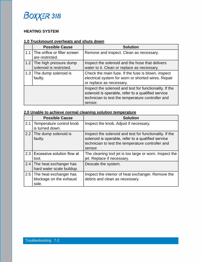
HEATING SYSTEM
1.0 Truckmount overheats and shuts downPossible Cause Solution
1.1 The orifice or filter screen are restricted.
Remove and inspect. Clean as necessary.
1.2 The high pressure dump solenoid is restricted.
Inspect the solenoid and the hose that delivers water to it. Clean or replace as necessary.
1.3 The dump solenoid is faulty.
Check the main fuse. If the fuse is blown, inspect electrical system for worn or shorted wires. Repair or replace as necessary.Inspect the solenoid and test for functionality. If the solenoid is operable, refer to a qualified service technician to test the temperature controller and sensor.
2.0 Unable to achieve normal cleaning solution temperaturePossible Cause Solution
2.1 Temperature control knob is turned down.
Inspect the knob. Adjust if necessary.
2.2 The dump solenoid is faulty.
Inspect the solenoid and test for functionality. If the solenoid is operable, refer to a qualified service technician to test the temperature controller and sensor.
2.3 Excessive solution flow at tool.
The cleaning tool jet is too large or worn. Inspect the jet. Replace if necessary.
2.4 The heat exchanger has hard water scale buildup.
Descale the system.
2.5 The heat exchanger has blockage on the exhaust side.
Inspect the interior of heat exchanger. Remove the debris and clean as necessary.

7-3: Troubleshooting
CHEMICAL SYSTEM
1.0 System will not primePossible Cause Solution
1.1 The check valves in chemical pump are faulty.
Remove the valves and inspect. Clean or replace as necessary.
1.2 The chemical pump diaphragm is faulty.
Remove and inspect. Replace as necessary.
1.3 The check valve in high pressure pump is faulty (piston which chemical pump is attached to).
Remove the valve and inspect. Clean or replace as necessary.
1.4 The filter on feed line in chemical jug is clogged.
Inspect and clean.
1.5 The feed line from chemical jug is loose, pinched or damaged.
Inspect and repair.
1.6 The chemical selector valve is faulty.
Inspect the valve for leaks between ports. Replace as necessary.
2.0 Chemical flow is unstable or lowPossible Cause Solution
2.1 Air is in the lines. Check that all fittings and connections are tight and in good condition. Repair or replace as necessary.
2.2 The check valve in high pressure pump is faulty (piston which chemical pump is attached to).
Remove the valve and inspect. Clean or replace as necessary.
2.3 The filter screen in the chemical jug is partially obstructed.
Inspect and clean.
2.4 The chemical selector valve is faulty.
Inspect the valve for leaks between ports. Replace as necessary.
2.5 The chemical metering valve is faulty.
Remove and inspect the valve. Clean or replace as necessary.
2.5 The high pressure check valve is faulty.
Remove and inspect the valve. Clean or rebuild as necessary.

Troubleshooting: 7-4
3.0 Chemical is present in water boxPossible Cause Solution
3.1 The chemical pump diaphragm is faulty.
Remove and inspect the chemical pump diaphragm. Replace as necessary.
3.2 The high pressure check valve is faulty.
Remove and inspect the valve. Clean or rebuild as necessary.

7-5: Troubleshooting
ENGINE
1.0 Will not turn overPossible Cause Solution
1.1 A loose or corroded battery terminal.
Clean and tighten the battery terminal connections.
1.2 The battery is dead. Recharge or replace the battery. Test the charging system. Repair if necessary.
Do not attempt to jump start the truckmount from a running vehicle. The amperage output from an automobile will damage the charging system of the truckmount.
1.3 The main fuse is blown. Check the main fuse.If the fuse is blown, inspect the electrical system for worn or shorted wires. Repair or replace as necessary.
1.4 The vacuum blower has seized.
Attempt to turn the coupler by hand. If it will not turn refer to the Vacuum System Troubleshooting Section.
1.5 The ignition switch is faulty.
Test to see if there is power both to and from the switch. Refer to the Electrical Section.
1.6 The starter solenoid is faulty.
Test to see if there is power to solenoid with ignition in “Start” position. Refer to Electrical Section.
1.7 The starter motor is faulty. Test to see if there is power to the motor with the ignition in “Start” position. Refer to the Electrical Section.
1.8 None of the above. Refer to a qualified service technician for further troubleshooting.
Troubleshooting: 7-6
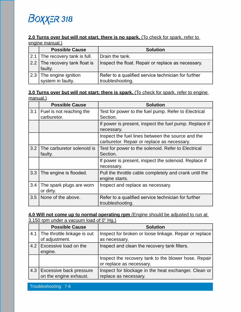
2.0 Turns over but will not start. there is no spark. (To check for spark, refer to engine manual.)
Possible Cause Solution2.1 The recovery tank is full. Drain the tank.2.2 The recovery tank float is
faulty.Inspect the float. Repair or replace as necessary.
2.3 The engine ignition system in faulty.
Refer to a qualified service technician for further troubleshooting.
3.0 Turns over but will not start; there is spark. (To check for spark, refer to engine manual.)
Possible Cause Solution3.1 Fuel is not reaching the
carburetor.Test for power to the fuel pump. Refer to Electrical Section.If power is present, inspect the fuel pump. Replace if necessary.Inspect the fuel lines between the source and the carburetor. Repair or replace as necessary.
3.2 The carburetor solenoid is faulty.
Test for power to the solenoid. Refer to Electrical Section.If power is present, inspect the solenoid. Replace if necessary.
3.3 The engine is flooded. Pull the throttle cable completely and crank until the engine starts.
3.4 The spark plugs are worn or dirty.
Inspect and replace as necessary.
3.5 None of the above. Refer to a qualified service technician for further troubleshooting.
4.0 Will not come up to normal operating rpm (Engine should be adjusted to run at 3,150 rpm under a vacuum load of 0” Hg.)
Possible Cause Solution4.1 The throttle linkage is out
of adjustment.Inspect for broken or loose linkage. Repair or replace as necessary.
4.2 Excessive load on the engine.
Inspect and clean the recovery tank filters.
Inspect the recovery tank to the blower hose. Repair or replace as necessary.
4.3 Excessive back pressure on the engine exhaust.
Inspect for blockage in the heat exchanger. Clean or replace as necessary.

7-7: Troubleshooting
5.0 Runs rough at high speedPossible Cause Solution
5.1 The spark plug(s) are faulty.
Remove and inspect the plugs. Clean or replace as necessary.
5.2 The spark plug wire(s) are faulty.
Inspect the wires and connectors for damage or loose connections. Repair or replace as necessary.
5.3 Inadequate fuel supply to the carburetor.
Check if the fuel pump is mounted in a vertical position near the fuel source. Correct if necessary.Check for blockage in the filter. Repair or replace as necessary.If operating altitudes have changed, contact your distributor to have the engine carburetor jets checked.
6.0 Runs rich.(Black smoke)Possible Cause Solution
6.1 The air filter is dirty. Inspect and replace as necessary.6.2 The choke is partially
closed.Inspect and adjust or repair as necessary.
6.3 Excessive fuel to the carburetor.
Check to see if the proper fuel pump is installed.
If operating altitudes have changed, contact your distributor to have the engine carburetor jets checked.

Troubleshooting: 7-8
7.0 Engine overheatsPossible Cause Solution
7.1 Poor ventilation in the van. Open all the van doors.Install a roof vent in the van.Remove any dividers or other objects impeding airflow around the truckmount.
7.2 Low oil level. Check the level and fill as necessary.
Running the engine with a low oil level can cause severe damage to the engine. If this situation occurs, the engine should be inspected by a qualified service technician.
7.3 The engine rpm is too high.
Check the engine rpm. Adjust as necessary to run at 3,150 rpm under a vacuum load of 0” Hg.
7.4 Excessive back pressure on the engine exhaust.
Inspect for blockage in the heat exchanger. Clean or replace as necessary.

7-9: Troubleshooting
HIGH PRESSURE SYSTEM
1.0 The pump will not come up to normal cleaning pressurePossible Cause Solution
1.1 The pressure adjusting valve is faulty.
Inspect the valve. Repair or replace if necessary.
1.2 Worn seals or valves in the pump.
Test the pump output volume directly from the pump at normal running rpm. If the volume is below the manufacturer’s specifications, replace the seals and inspect for defective valves.
1.3 The pump rpm is too low. Check for a loose pump belt. Adjust or replace as necessary.Check the engine rpm and adjust as necessary to 3,150 rpm under a 0” Hg vacuum load.
1.4 The primary orifice is missing or loose.
Remove and inspect. Tighten or replace as necessary.
1.5 The primary and secondary orifices have been installed incorrectly.
Inspect and reverse if necessary. Refer to the Machine Assemblies & Parts List Section.
1.6 The primary orifice is worn.
Measure the orifice size and replace as necessary. Correct size is 0.039”.
2.0 No pressure reading on gaugePossible Cause Solution
2.1 The pump belt is broken. Inspect and replace if necessary.2.2 The gauge is faulty. Replace the gauge.2.3 Water box is empty. Fill the water box.2.4 Water box switch is faulty. Replace water box switch.

Troubleshooting: 7-10
3.0 The psi gauge reads normal; low pressure from wandPossible Cause Solution
3.1 Restriction in the cleaning tool.
Inspect the tool jet(s) and clean or replace as necessary.Inspect any filters in the cleaning tool and clean or replace as necessary.
3.2 Faulty quick connect in the system.
Inspect each quick connect and replace as necessary.
3.3 Restriction in one of the solution hoses.
Remove the quick connects and inspect hoses. Clean or replace as necessary.
3.4 Hard water deposits restricting the system.
Descale the truckmount.
4.0 Pressure pulsationPossible Cause Solution
4.1 Air leak between the water box and pump.
Check all the hoses and fittings for cuts, breaks, cracks, etc. Repair as necessary.
4.2 The check valve(s) in the pump are faulty.
Remove each valve and inspect for correct operation. See the Machine Maintenance Section.
4.3 The chemical pump is not primed.
Prime the chemical pump.
5.0 Water box empty or fills slowlyPossible Cause Solution
5.1 Restriction in the water supply system.
Inspect the supply system from the source through the incoming quick connect.
5.2 The float valve in the water box is faulty.
Disassemble and inspect the valve. Repair or replace as necessary.
6.0 The water box overflowsPossible Cause Solution
6.1 The float valve in the water box is faulty.
Disassemble and inspect the valve. Repair or replace as necessary.
6.2 The float has absorbed water and lost buoyancy.
Detach the float and check to see if it will float to the surface. Replace the valve as necessary.
6.3 The float has come out of adjustment.
Adjust the float as necessary.

7-11: Troubleshooting
VACUUM SYSTEM
1.0 A weak vacuum at wand. The gauge reads normal.Possible Cause Solution
1.1 Blockage in the hoses or wand tube
Disconnect the hoses and check for an obstruction.
1.2 Excessive length of hose connected to the truckmount
Do not attach excessive lengths of hose.
2.0 A weak vacuumPossible Cause Solution
2.1 Air leak somewhere in the vacuum system.
Check the vacuum relief valve for proper adjustment.
Carefully check all the vacuum hoses for a cut or break.Check the recovery tank lid gasket.Make sure the recovery tank drain valve is fully closed.
2.2 The vacuum blower is turning too slowly.
Check the rpm of the engine. Adjust as necessary to 3,150 rpm under a 0” Hg vacuum load.
2.3 The vacuum gauge is defective.
Test the gauge and replace if necessary.
3.0 The vacuum gauge reads too high with no hoses attachedPossible Cause Solution
3.1 The filter in recovery tank is clogged.
Remove and clean or replace as necessary.
3.2 The hose from recovery tank to the vacuum blower is collapsed internally.
Inspect and replace as necessary.
4.0 Excessive noise produced by the blowerPossible Cause Solution
4.1 The blower is low on oil. Inspect the oil levels and replenish as necessary. Note: Running the blower with low oil levels can cause severe damage. If this situation occurs the blower should be inspected by a qualified service technician.
4.2 The vacuum blower has internal damage.
Refer to a qualified service technician.

Troubleshooting: 7-12
5.0 The vacuum blower is locked and will not turnPossible Cause Solution
5.1 Truckmount has been inactive for a period of time and the blower was not properly lubricated prior to final shutdown. Rust has possibly built up on the internal surfaces.
Spray penetrating oil into the blower and let sit for at least 1 hour. Then very carefully use pipe wrench on the outer diameter of the pulley on the coupler to attempt to free lobes of the blower. Do not use a wrench directly on the blower shaft.
If unable to free up the blower in this manner, refer to a qualified service technician.
5.2 There is internal damage to the blower.
Refer to a qualified service technician.
6.0 Water in truckmount exhaustPossible Cause Solution
6.1 The recovery tank has been filled with foam or overfilled with water.
Inspect the recovery tank. If full, drain the tank.
Inspect the high level shutoff switch for proper operation. Clean or replace the switch as necessary.If foam is in recovery tank, use de-foamer on the carpet being cleaned.
6.2 Condensation in system. This will be more common in cool weather and humid climates. If this is the cause, it should dissipate after a few minutes of running.
6.3 The heat exchanger is leaking water.
Inspect and repair or replace as necessary.

8-1: Assemblies and Parts Lists
8 - Assemblies and Parts ListThis section of the manual provides detailed illustrations and parts lists for the following assemblies.
When ordering parts for assemblies, first refer to the appropriate assembly listed here and then find the part number listed on that specific page. In most cases, you do not have to order the entire assembly to get a part.
If you have an electronic copy (a .pdf) of this manual, you can search for the part number by pressing the CTRL key and the F key at the same time. This will “pop up” the Find window on your monitor. Type the part number, including dashes, into the Find window and press the Enter key.
� Console Assembly Parts List ...............................................................................8-8
� Frame Assembly Parts List ................................................................................8-11
� Engine Assembly Parts List ...............................................................................8-14
� Blower Assembly Parts List ................................................................................8-16
� Pump Assembly Parts List .................................................................................8-18
� Heat Exchanger Assembly Parts List .................................................................8-20
� Silencer Assembly Parts List ..............................................................................8-21
� Water Box Assembly Parts List ..........................................................................8-23
� Dash Assembly Parts List ..................................................................................8-26
� Differential Check Valve Assembly Parts List .....................................................8-27
� By-Pass Valve Assembly Parts List ....................................................................8-28
� Orifice Assembly Parts List ................................................................................8-29
� Idler Pulley Assembly Parts List .........................................................................8-30
� Exhaust Assembly Parts List ..............................................................................8-31
� 65 Gallon Universal Recovery Tank (URT) Assembly Parts List ........................8-34
� 100 Gallon Universal Recovery Tank (URT) Assembly Parts List ......................8-36
� 100 Gallon Universal Recovery Tank (URT)
Cover Assembly Parts List .................................................................................8-37
� Vacuum Relief Valve Assembly Parts List ..........................................................8-38
� 70 Gallon Fresh Water Tank (FWT) Assembly Parts List ...................................8-41
� Dura-Flow APO 90 Degree Assembly Parts List ................................................8-43
� APO Pump Assembly Parts List .........................................................................8-44
� APO Connection Kit Assembly Parts List ...........................................................8-45
� Hose Routings ...................................................................................................8-46

Assemblies and Parts Lists: 8-2
Figure 8-1. Adhesive/Sealant Material Reference
Some of the illustrations in this section reference sealants, thread lockers, adhesive, primer, anti-seize and lubricant specifications that are used in the construction of HydraMaster equipment.
Refer to Figure 8-1 to identify those substances such as A1, A2 and so forth. Equivalent products are acceptable if they meet or exceed current specifications and are approved by HydraMaster.

8-3: Assemblies and Parts Lists
Figure 8-2. Console Assembly - View 1 of 5610-050-737 Rev. A

Assemblies and Parts Lists: 8-4
Figure 8-3. Console Assembly - View 2 of 5610-050-737 Rev. A

8-5: Assemblies and Parts Lists
Figure 8-4. Console Assembly - View 3 of 5610-050-737 Rev. A

Assemblies and Parts Lists: 8-6
Figure 8-5. Console Assembly - View 4 of 5610-050-737 Rev. A

8-7: Assemblies and Parts Lists
Figure 8-6. Console Assembly - View 5 of 5610-050-737 Rev. A
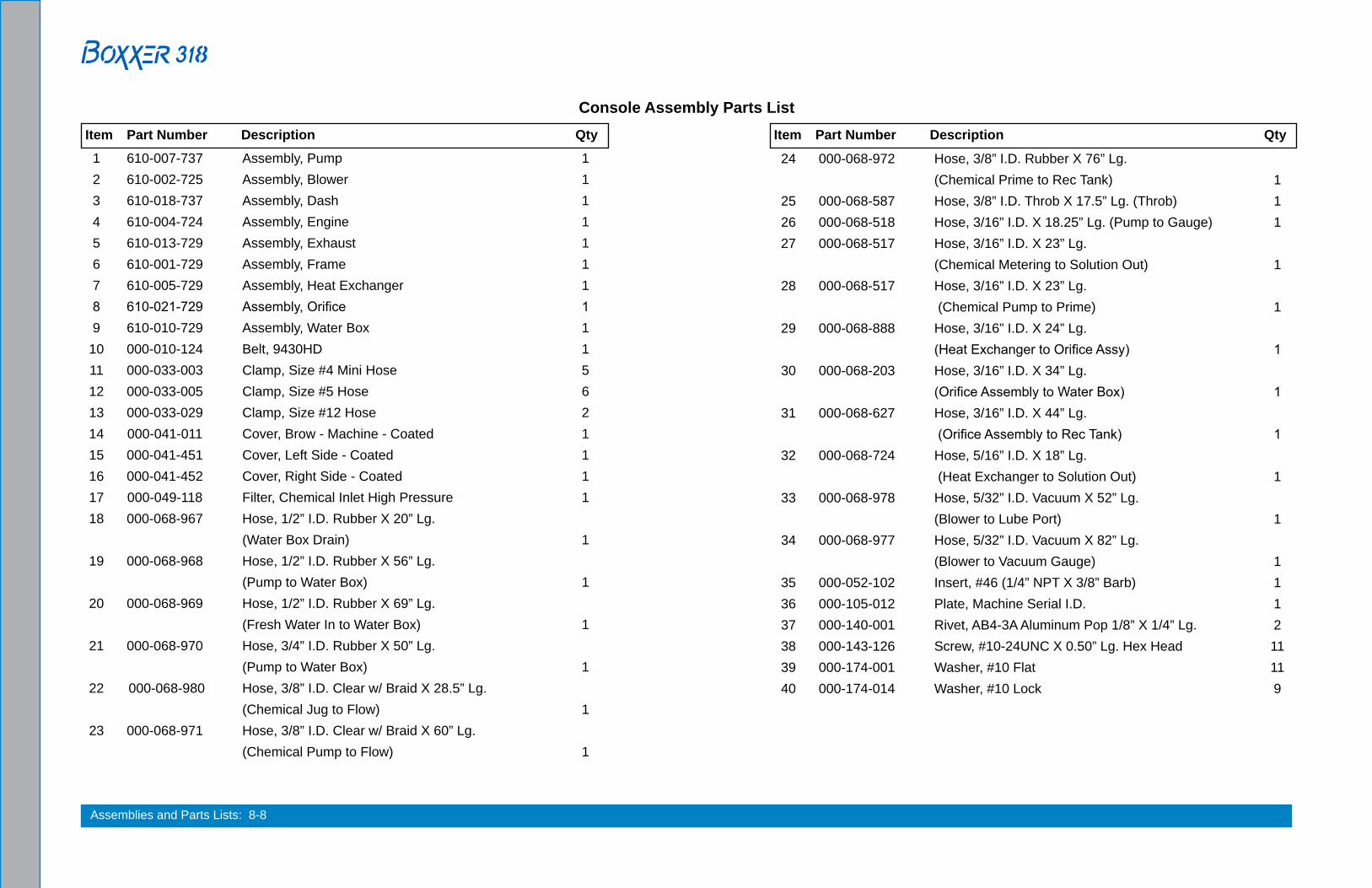
Assemblies and Parts Lists: 8-8
Console Assembly Parts List
1 610-007-737 Assembly, Pump 1 2 610-002-725 Assembly, Blower 1 3 610-018-737 Assembly, Dash 1 4 610-004-724 Assembly, Engine 1 5 610-013-729 Assembly, Exhaust 1 6 610-001-729 Assembly, Frame 1 7 610-005-729 Assembly, Heat Exchanger 1 8 610-021-729 Assembly, Orifice 1 9 610-010-729 Assembly, Water Box 1 10 000-010-124 Belt, 9430HD 1 11 000-033-003 Clamp, Size #4 Mini Hose 5 12 000-033-005 Clamp, Size #5 Hose 6 13 000-033-029 Clamp, Size #12 Hose 2 14 000-041-011 Cover, Brow - Machine - Coated 1 15 000-041-451 Cover, Left Side - Coated 1 16 000-041-452 Cover, Right Side - Coated 1 17 000-049-118 Filter, Chemical Inlet High Pressure 1 18 000-068-967 Hose, 1/2” I.D. Rubber X 20” Lg. (Water Box Drain) 1 19 000-068-968 Hose, 1/2” I.D. Rubber X 56” Lg. (Pump to Water Box) 1 20 000-068-969 Hose, 1/2” I.D. Rubber X 69” Lg. (Fresh Water In to Water Box) 1 21 000-068-970 Hose, 3/4” I.D. Rubber X 50” Lg. (Pump to Water Box) 1 22 000-068-980 Hose, 3/8” I.D. Clear w/ Braid X 28.5” Lg. (Chemical Jug to Flow) 1 23 000-068-971 Hose, 3/8” I.D. Clear w/ Braid X 60” Lg. (Chemical Pump to Flow) 1
Item Part Number Description Qty
24 000-068-972 Hose, 3/8” I.D. Rubber X 76” Lg. (Chemical Prime to Rec Tank) 1 25 000-068-587 Hose, 3/8” I.D. Throb X 17.5” Lg. (Throb) 1 26 000-068-518 Hose, 3/16” I.D. X 18.25” Lg. (Pump to Gauge) 1 27 000-068-517 Hose, 3/16” I.D. X 23” Lg. (Chemical Metering to Solution Out) 1 28 000-068-517 Hose, 3/16” I.D. X 23” Lg. (Chemical Pump to Prime) 1 29 000-068-888 Hose, 3/16” I.D. X 24” Lg. (Heat Exchanger to Orifice Assy) 1 30 000-068-203 Hose, 3/16” I.D. X 34” Lg. (Orifice Assembly to Water Box) 1 31 000-068-627 Hose, 3/16” I.D. X 44” Lg. (Orifice Assembly to Rec Tank) 1 32 000-068-724 Hose, 5/16” I.D. X 18” Lg. (Heat Exchanger to Solution Out) 1 33 000-068-978 Hose, 5/32” I.D. Vacuum X 52” Lg. (Blower to Lube Port) 1 34 000-068-977 Hose, 5/32” I.D. Vacuum X 82” Lg. (Blower to Vacuum Gauge) 1 35 000-052-102 Insert, #46 (1/4” NPT X 3/8” Barb) 1 36 000-105-012 Plate, Machine Serial I.D. 1 37 000-140-001 Rivet, AB4-3A Aluminum Pop 1/8” X 1/4” Lg. 2 38 000-143-126 Screw, #10-24UNC X 0.50” Lg. Hex Head 11 39 000-174-001 Washer, #10 Flat 11 40 000-174-014 Washer, #10 Lock 9
Item Part Number Description Qty

8-9: Assemblies and Parts Lists
Figure 8-7. Frame Assembly - View 1 of 2610-001-729 Rev. E (P/N 000-081-327 available only as part of
label set P/N 000-081-039.)

Assemblies and Parts Lists: 8-10
Figure 8-8. Frame Assembly -View 2 of 2610-001-729 Rev. E
(P/N 000-081-327 available only as part of label set P/N 000-081-039.)

8-11: Assemblies and Parts Lists
Frame Assembly Parts List
1 610-021-009 Assembly, Idler Pulley 1 2 610-021-724 Assembly, Silencer 1 3 000-015-177 Bracket, Dual Heat Exchanger Mounting - Left - Coated 1 4 000-027-110 Cap, 2” X 3” Frame End 2 5 000-033-050 Clamp, 1-3/4” Cushion Loop 1 6 000-033-057 Clamp, 1” Cushion Loop 2 7 000-033-067 Clamp, 2” Cushion Loop 2 8 000-055-195 Frame, Complete - Coated 1 9 000-056-006 Fuse Holder, In-Line - Weatherproof 2 10 000-056-011 Fuse, 30 Amp 2 11 000-094-034 Nut, #10-24UNC Nylock 3
Item Part Number Description Qty Item Part Number Description Qty
12 000-143-012 Screw, 5/16”-18UNC X 3/4” Lg. 1 13 000-143-583 Screw, #10-24UNC X 0.50” Lg. Hex Head Flange Z/P 8 14 000-157-022 Switch, Relay 1 15 000-131-131 Trimlok, 3/8” X 1/8” Rubber - Bulk 1 16 000-174-004 Washer, 5/16” Flat, USS 1 17 000-174-018 Washer, 5/16” Lock 1

Assemblies and Parts Lists: 8-12
Figure 8-9. Engine Assembly - Part 1 of 2610-004-724 Rev. G
DETAIL VIEW A

8-13: Assemblies and Parts Lists
Figure 8-10. Engine Assembly - Part 2 of 2610-004-724 Rev. G

Assemblies and Parts Lists: 8-14
Engine Assembly Parts List
1 000-020-025 Bushing, H X 1” 1 2 000-033-057 Clamp, 1” Cushion Loop 1 3 000-033-117 Clamp, 1” Cushion Loop w/ 7/16 Mount Hole 2 4 000-033-046 Clamp, 1/2” Wide X 1/2” Tube 1 5 000-033-003 Clamp, Size #4 Mini Hose 1 6 000-039-054 Coupler, 40 Series 1 7 000-047-028 Engine, 18Hp 1 8 000-049-258 Filter, Fuel 1 9 000-068-219 Hose Assembly, Pump Drain 1 10 000-068-157 Hose, 1/4” Fuel, Low Perm, Non Fuel Injected Only 1 11 000-068-979 Hose, 1/4” I.D. Fuel Low Perm X 120” Lg. 1
12 000-131-139 Insulation, 1” Hi-Temp Alum Sleeve X 60” Lg. 1 13 000-077-010 Key, 1/4” X 1-1/2” Lg. Class 2 Fit 2 14 000-094-012 Nut, 5/16”-18UNC Hex 1 15 000-094-081 Nut, 5/16”-18UNC Hex 2 Way Locking 4 16 000-109-040 Pulley, AK47-H 1 17 000-143-659 Screw, 5/16”-18UNC X 3.5” Lg. Grade 8 2 18 000-143-660 Screw, 5/16”-18UNC X 4.0” Lg., Hex Head 2 19 000-152-009 Sleeve, Solenoid Insulator 1 20 000-174-049 Washer, 5/16” Flat 6 21 000-174-004 Washer, 5/16” Flat, USS 4
Item Part Number Description Qty Item Part Number Description Qty

8-15: Assemblies and Parts Lists
Figure 8-11. Blower Assembly - View 1 of 2610-002-725 Rev. G
See Figure 8-1 for adhesive/sealant information.

Assemblies and Parts Lists: 8-16
Figure 8-12. Blower Assembly - View 2 of 2610-002-725 Rev. G
Blower Assembly Parts List
1 000-001-140 Adapter, 2 1/2” NPT to 2 1/2” O.D.Tube - Coated 1 2 000-001-141 Adapter, 2.5” MNPT X 2.5” O.D.Elbow - Coated 1 3 000-111-134 Blower, 3006 Competitor 1 4 000-052-061 Bushing, 3/8” NPT X 1/4” FPT 2 5 000-033-057 Clamp, 1” Cushion Loop 2 6 000-052-085 Elbow, 1/4” NPT Street 2 7 000-068-794 Hose Assembly, 3/8” I.D. Hi Temp Rubber X 17” Lg. Drain 1 8 000-068-794 Hose Assembly, 3/8” I.D. Hi Temp Rubber X 17” Lg. Drain 1 9 000-052-106 Insert, 1/8” NPT X 5/32” Barb X 90 Degree 2 10 000-094-015 Nut, 3/8”-16UNC Hex 2-Way Locking 4 11 000-143-200 Screw, 3/8”-16UNC X 1.5” Lg. Hex Head Grade 8 4 12 000-174-004 Washer, 5/16” Flat, USS 8 13 000-174-068 Washer, Blower Feet - Coated 4
Item Part Number Description Qty
See Figure 8-1 for adhesive/sealant information.

8-17: Assemblies and Parts Lists
Figure 8-13. Pump Assembly - View 1 of 2610-007-737 Rev. A

Assemblies and Parts Lists: 8-18
Pump Assembly Parts List
1 000-001-096 Adapter, Chemical Pump 1 2 610-009-729 Assembly, By-Pass Valve 1 3 000-036-008 Clutch, 7” O.D. 24mm Single Groove 1 4 000-052-084 Elbow, 1/8” NPT Street 1 5 000-052-531 Elbow, 1/8” NPT X 1/4” SAE 2 6 000-052-086 Elbow, 3/8” NPT Street 1 7 000-068-219 Hose, Drain 1 8 000-052-099 Insert, #26 (1/8” NPT X 3/8” Barb) 1 9 000-052-129 Insert, #812, 1/2NPT X 3/4 Hose 1 10 000-094-038 Nut, 5/16”-18UNC Hex Nylock 2 11 000-097-057 O-Ring, Adapter - Chemical Pump 1 12 000-105-148 Plate, Clutch Mount Comet Pump 1 13 000-111-184 Pump, GP Chemical 1 14 000-111-042 Pump 1 15 000-143-375 Screw, 5/16”-18UNC X 1.75” Lg. Hex Head Grd. 8 Z/P 2 16 000-143-012 Screw, 5/16”-18UNC X 3/4” Lg. 2 17 000-143-221 Screw, M6-1 X 14mm Lg. Hex Head 4 18 000-174-004 Washer, 5/16” Flat, USS 6
Item Part Number Description Qty
Figure 8-14. Pump Assembly - View 2 of 2610-007-737 Rev. A

8-19: Assemblies and Parts Lists
Figure 8-15. Heat Exchanger Assembly610-005-729 Rev. C

Assemblies and Parts Lists: 8-20
Heat Exchanger Assembly Parts List
1 000-052-738 Adapter, 1/4” NPT X 1/2” FPT 1 2 000-013-115 Box, Outlet Plenum, Steel - Coated 1 3 000-013-118 Box, Plenum Inlet, Steel - Coated 1 4 000-052-061 Bushing, 3/8” NPT X 1/4” FPT 1 5 000-033-012 Clamp, Size #44 Hose 2 6 000-052-113 Cross, 3/8” FPT 1 7 000-038-072 Heat Exchanger, 4 Row 1 8 000-068-986 Hose, 2.5” Heat Flex Ns X 15” Lg. 1 9 000-052-528 Nipple, 3/8” M Jic X 3/8” NPT 1
Item Part Number Description Qty Item Part Number Description Qty
10 000-052-128 Nipple, 3/8” Mpt X 3/8” SAE Flare 1 11 000-052-074 Nipple, 3/8” NPT Hex 1 12 000-052-662 Nipple, 3/8” NPT X 1/4” M SAE 1 13 000-140-021 Rivet, 1/4” Blind X 0.50” Lg. 32 14 000-143-583 Screw, #10-24UNC X 0.50” Lg. Hex Head Flange Z/P 4 15 - - - Sensor (Comes with 000-149-025) 1 16 000-149-027 Sensor, 285F Nason- 3/8” NPT 1 17 000-052-023 Tee, 3/8” NPT Male Street 1

8-21: Assemblies and Parts Lists
Silencer Assembly Parts List
Figure 8-16. Silencer Assembly610-021-724 Rev. B
1 000-033-012 Clamp, Size #44 Hose 4 2 000-068-104 Hose, Ø2.5” I.D. X 2.5” Lg. 2 3 000-093-108 Silencer, Ø2.5” O.D. Inlet/Outlet - Coated 1
Item Part Number Description Qty
3
2
1
2
1

Assemblies and Parts Lists: 8-22
Figure 8-17. Water Box Assembly610-010-729 Rev. B

8-23: Assemblies and Parts Lists
Water Box Assembly Parts ListItem Part Number Description Qty Item Part Number Description Qty
1 000-169-235 Assembly, Robert Float Valve 1 2 000-052-660 Bulkhead, 3/8” FPT X 3/8” FPT 1 3 000-033-003 Clamp, Size #4 Mini Hose 1 4 000-041-005 Cover, 6” Access 1 5 000-052-355 Elbow, 3/8” NPT X 1/2” Hose, GFBN 2 6 000-068-827 Hose, 3/8” Clear w/ Braid X 8” Lg. 1 7 000-052-104 Insert, #66 (3/8” NPT X 3/8” Barb) 1 8 000-052-661 Insert, 3/4” Barb X Straight 1 9 000-052-662 Nipple, 3/8” NPT X 1/4” M SAE 1 10 000-094-097 Nut, 1”-14UNS Brass 4
11 000-097-041 O-Ring, 1/2” Bulk Head 2 12 000-143-314 Screw, #8 X 1/2” Lg. Pan Head 6 13 000-143-017-1 Screw, 3/8”-16UNC X 3/4” Lg. Hex Head 3 14 000-157-0801 Switch, w/Protector, Polypropylene Barrel 1 15 000-159-190 Tank, Poly Water Box - 4 Gallon - Modified 1 16 000-052-156 Tee, 1/4” Plastic 1 17 000-052-023 Tee, 3/8” NPT Male Street 1 18 000-174-063 Washer, 1.5” O.D. X 1.073” I.D. X 0.075” Thk. 2 19 000-174-032 Washer, 3/8” Flat 3 20 000-174-028 Washer, 7/8” I.D. X 1.50” O.D. X 0.090” Thk. 2

Assemblies and Parts Lists: 8-24
Figure 8-18. Dash Assembly - View 1 of 2610-018-737 Rev. A

8-25: Assemblies and Parts Lists
Figure 8-19. Dash Assembly - View 2 of 2610-018-737 Rev. A
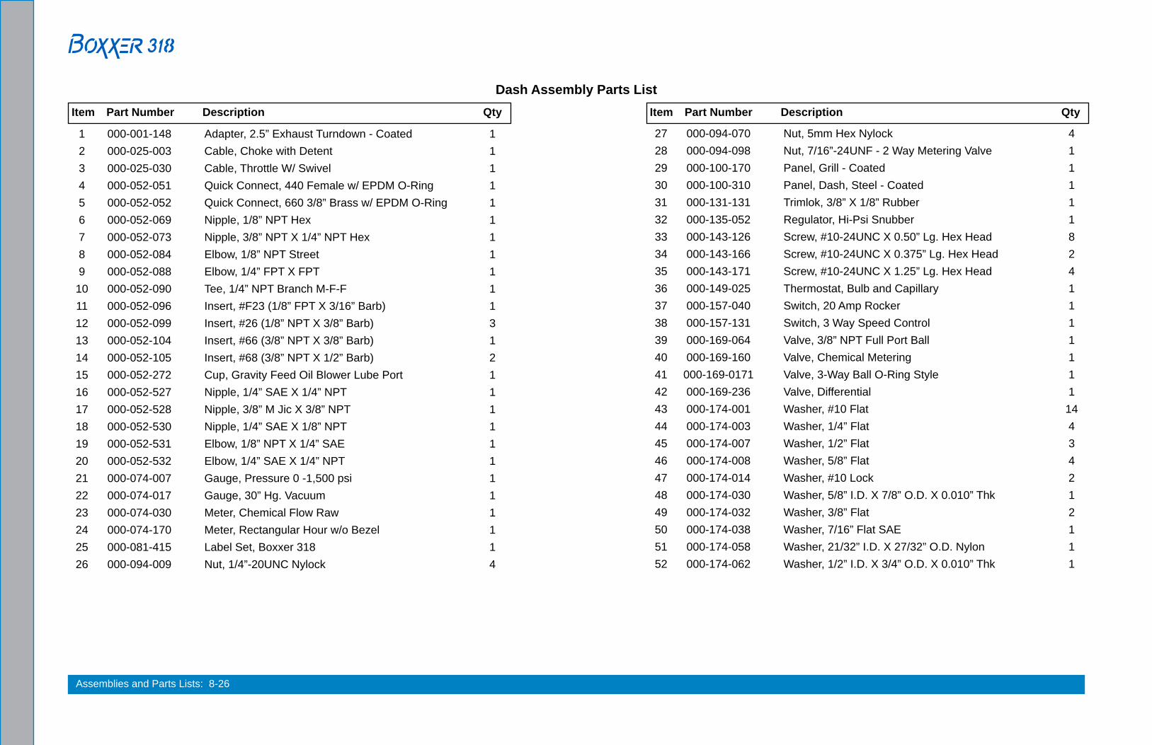
Assemblies and Parts Lists: 8-26
Dash Assembly Parts List
1 000-001-148 Adapter, 2.5” Exhaust Turndown - Coated 1 2 000-025-003 Cable, Choke with Detent 1 3 000-025-030 Cable, Throttle W/ Swivel 1 4 000-052-051 Quick Connect, 440 Female w/ EPDM O-Ring 1 5 000-052-052 Quick Connect, 660 3/8” Brass w/ EPDM O-Ring 1 6 000-052-069 Nipple, 1/8” NPT Hex 1 7 000-052-073 Nipple, 3/8” NPT X 1/4” NPT Hex 1 8 000-052-084 Elbow, 1/8” NPT Street 1 9 000-052-088 Elbow, 1/4” FPT X FPT 1 10 000-052-090 Tee, 1/4” NPT Branch M-F-F 1 11 000-052-096 Insert, #F23 (1/8” FPT X 3/16” Barb) 1 12 000-052-099 Insert, #26 (1/8” NPT X 3/8” Barb) 3 13 000-052-104 Insert, #66 (3/8” NPT X 3/8” Barb) 1 14 000-052-105 Insert, #68 (3/8” NPT X 1/2” Barb) 2 15 000-052-272 Cup, Gravity Feed Oil Blower Lube Port 1 16 000-052-527 Nipple, 1/4” SAE X 1/4” NPT 1 17 000-052-528 Nipple, 3/8” M Jic X 3/8” NPT 1 18 000-052-530 Nipple, 1/4” SAE X 1/8” NPT 1 19 000-052-531 Elbow, 1/8” NPT X 1/4” SAE 1 20 000-052-532 Elbow, 1/4” SAE X 1/4” NPT 1 21 000-074-007 Gauge, Pressure 0 -1,500 psi 1 22 000-074-017 Gauge, 30” Hg. Vacuum 1 23 000-074-030 Meter, Chemical Flow Raw 1 24 000-074-170 Meter, Rectangular Hour w/o Bezel 1 25 000-081-415 Label Set, Boxxer 318 1 26 000-094-009 Nut, 1/4”-20UNC Nylock 4
27 000-094-070 Nut, 5mm Hex Nylock 4 28 000-094-098 Nut, 7/16”-24UNF - 2 Way Metering Valve 1 29 000-100-170 Panel, Grill - Coated 1 30 000-100-310 Panel, Dash, Steel - Coated 1 31 000-131-131 Trimlok, 3/8” X 1/8” Rubber 1 32 000-135-052 Regulator, Hi-Psi Snubber 1 33 000-143-126 Screw, #10-24UNC X 0.50” Lg. Hex Head 8 34 000-143-166 Screw, #10-24UNC X 0.375” Lg. Hex Head 2 35 000-143-171 Screw, #10-24UNC X 1.25” Lg. Hex Head 4 36 000-149-025 Thermostat, Bulb and Capillary 1 37 000-157-040 Switch, 20 Amp Rocker 1 38 000-157-131 Switch, 3 Way Speed Control 1 39 000-169-064 Valve, 3/8” NPT Full Port Ball 1 40 000-169-160 Valve, Chemical Metering 1 41 000-169-0171 Valve, 3-Way Ball O-Ring Style 1 42 000-169-236 Valve, Differential 1 43 000-174-001 Washer, #10 Flat 14 44 000-174-003 Washer, 1/4” Flat 4 45 000-174-007 Washer, 1/2” Flat 3 46 000-174-008 Washer, 5/8” Flat 4 47 000-174-014 Washer, #10 Lock 2 48 000-174-030 Washer, 5/8” I.D. X 7/8” O.D. X 0.010” Thk 1 49 000-174-032 Washer, 3/8” Flat 2 50 000-174-038 Washer, 7/16” Flat SAE 1 51 000-174-058 Washer, 21/32” I.D. X 27/32” O.D. Nylon 1 52 000-174-062 Washer, 1/2” I.D. X 3/4” O.D. X 0.010” Thk 1
Item Part Number Description Qty Item Part Number Description Qty

8-27: Assemblies and Parts Lists
3
7
1
6
2
4
5
Apply O-ring grease or equivalent to items 5 and 4 prior to installation.
Differential Check Valve Assembly Parts List
1 000-005-012 Ball, 0.500 Diameter Stainless Steel 1 2 000-107-258 Body, Differential Check Valve 1 3 000-106-180 Cap, Differential Check Valve 1 4 000-097-056 O-Ring, Check Valve Plug, An Size 1
5 000-097-054 O-Ring, Chemical Pump Valve 1 6 000-148-012 Seat, Differential Check Valve 1 7 000-155-106 Spring, Differential Check Valve 1
Item Part Number Description Qty Item Part Number Description Qty
Figure 8-20. Differential Check Valve Assembly000-169-236 Rev. B

Assemblies and Parts Lists: 8-28
By-Pass Valve Assembly Parts List
Figure 8-21. By-Pass Valve Assembly610-009-729 Rev. B
1 000-052-086 Elbow, 3/8” NPT Street 1 2 000-052-105 Insert, #68 (3/8” NPT X 1/2” Barb) 2 3 000-052-128 Nipple, 3/8” MPT X 3/8” SAE Flare 1 4 000-052-074 Nipple, 3/8” NPT Hex 1 5 000-106-008 Plug, 3/8” NPT Allen Head 2 6 000-052-023 Tee, 3/8” NPT Male Street 1 7 000-169-351 Valve, Pressure Regulator-Modified * 1
Item Part Number Description Qty
5
7
4
1
62
3
A3
A3
A3
A3
A3
A3
* Order P/N 000-078-582 for the valve repair kit.
See Figure 8-1 for adhesive/sealant information.

8-29: Assemblies and Parts Lists
Figure 8-22. Orifice Assembly610-021-729
Orifice Assembly Parts List
1 000-052-084 Elbow, 1/8” NPT Street 1 2 000-049-052 Filter Cartridge,1/4” Brass 2 3 000-052-153 Housing, Stabilizer Nozzle 2 4 000-052-530 Nipple, 1/4” SAE X 1/8” NPT 1 5 000-052-586 Nipple, 1/8” FPT X 1/4” SAE 2 6 000-052-582 Nipple, Tee Jet Style Collar X 1/8” NPT 2 7 000-094-028 Nut, Brass Jet Assembly 2 8 000-180-010 Orifice, 0.039” Plate 1 9 000-180-024 Orifice, 0.067” Plate 1 10 000-052-092 Tee, 1/8” FPT 1
Item Part Number Description Qty
410
3
2X2
2X8
6
2X5
2X
7
2X
1
9
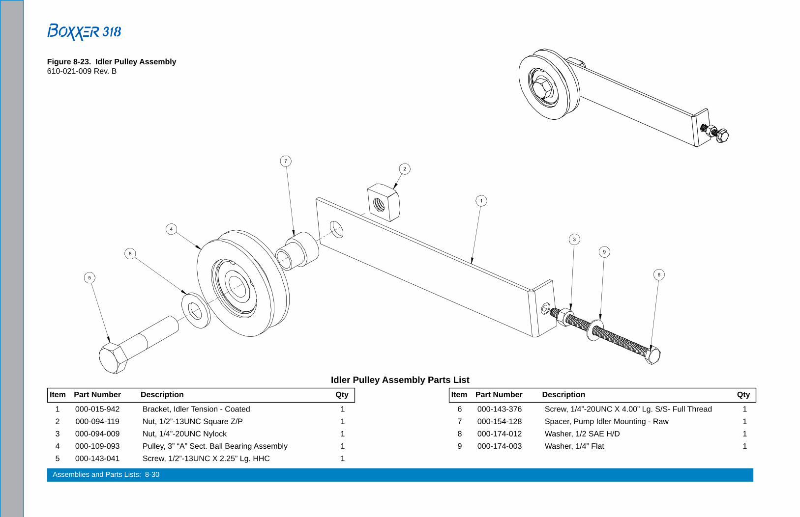
Assemblies and Parts Lists: 8-30
Figure 8-23. Idler Pulley Assembly610-021-009 Rev. B
Idler Pulley Assembly Parts List
1 000-015-942 Bracket, Idler Tension - Coated 1 2 000-094-119 Nut, 1/2”-13UNC Square Z/P 1 3 000-094-009 Nut, 1/4”-20UNC Nylock 1 4 000-109-093 Pulley, 3” “A” Sect. Ball Bearing Assembly 1 5 000-143-041 Screw, 1/2”-13UNC X 2.25” Lg. HHC 1
Item Part Number Description Qty Item Part Number Description Qty
6 000-143-376 Screw, 1/4”-20UNC X 4.00” Lg. S/S- Full Thread 1 7 000-154-128 Spacer, Pump Idler Mounting - Raw 1 8 000-174-012 Washer, 1/2 SAE H/D 1 9 000-174-003 Washer, 1/4” Flat 1

8-31: Assemblies and Parts Lists
Figure 8-24. Exhaust Assembly610-013-729 Rev. B
Exhaust Assembly Parts List
1 000-001-116 Adapter, N1.50” F Slip to Flare 1 2 000-033-068 Clamp, 1-1/2” Exhaust 1 3 000-105-181 Flange, Ø1.50” Exhaust Donut - Coated 1 4 000-057-177 Gasket, Exhaust Donut 1.50” 1 5 000-057-212 Gasket, Half Donut 1 6 000-057-209 Gasket, Ø2.5” X 3.5” BCD 1 7 000-094-081 Nut, 5/16”-18UNC Hex 2 Way Locking 6 8 000-143-001 Screw, 1/4”-20UNC X 3/4” Lg. Hex Head 4 9 000-143-124 Screw, 5/16”-18UNC X 1.75” Lg. Hex Head 4 10 000-125-128 Tube, 1-3/8” O.D. X 1/8” Wall X 7/8” Long 1 11 000-125-156 Tube, Exhaust 6.875” Lg. w/ Flare 1 12 000-125-227 Tube, Lower Exhaust Weldment 1 13 000-125-228 Tube, Upper Exhaust Weldment 1 14 000-174-003 Washer, 1/4” Flat 4 15 000-174-049 Washer, 5/16” Flat 10
Item Part Number Description Qty

Assemblies and Parts Lists: 8-32
Figure 8-25. 65 Gallon Universal Recovery Tank (URT) Assembly View 1 of 2610-003-729 Rev. B

8-33: Assemblies and Parts Lists
Figure 8-26. 65 Gallon Universal Recovery Tank (URT) Assembly - View 2 of 2610-003-729 Rev. B

Assemblies and Parts Lists: 8-34
65 Gallon Universal Recovery Tank (URT) Assembly Parts List
1 000-052-219 Adapter, 2” NPT X 2” F Slip 1 2 000-001-134 Adapter, Ø2.5” Tank X 90 Degree Blower Hose - Coated 1 3 000-012-002 Block, 6 Post Terminal 1 4 000-015-182 Bracket, Vacuum Relief Valve - Fabricated 1 5 000-027-032 Cap, Spun Vacuum Relief Valve 1 6 000-041-459 Cover, 50 URT 1 Port - Coated 1 7 000-052-085 Elbow, 1/4” NPT Street 2 8 000-052-222 Elbow, 2” Barb X 2” FPT 1 9 000-049-153 Filter, Flat - Universal Recovery Tank 1 10 000-049-155 Filter, Recovery Tank Basket - Small 1 11 000-157-091 Float, Lever Switch 1 12 000-057-015 Gasket, 1-1/2” Bulkhead Fitting 1 13 000-057-206 Gasket, Adapter - URT 2 14 000-052-102 Insert, #46 (1/4” NPT X 3/8” Barb) 1 15 000-081-332 Label, Maintenance and Lube Schedule 1 16 000-086-008 Latch, Bungee 2 17 - - - Latch, Bungee - Strike (Part of 000-086-008) 2 18 000-052-662 Nipple, 3/8” NPT X 1/4” M SAE 1 19 000-052-073 Nipple, 3/8” NPT X 1/4” NPT Hex 1 20 000-094-113 Nut, 1/4”-20UNC Neoprene Wellnut 4 21 000-094-009 Nut, 1/4”-20UNC Nylock 8
Item Part Number Description Qty Item Part Number Description Qty
22 000-094-101 Nut, 3/8”-16 UNC Hex Jam 1 23 000-094-077 Nut, 3/8”-16UNC X 1.00” O.D. Knurled 2 24 000-094-063 Nut, #6-32UNC Nylock 8 25 000-094-059 Nut, #8-32UNC Nylock 2 26 000-105-332 Plate, Vacuum Relief Valve Mounting - Coated 1 27 000-106-046 Plug, 1-1/4” NPT 1 28 000-106-049 Plug, 1” NPT Black Nylon 1 29 000-135-051 Regulator,3 Amp 1000 PIV Diode 1 30 000-143-002 Screw, 1/4”-20UNC X 1.00” Lg. Hex Head 12 31 000-143-198 Screw, 3/8”-16UNC X 4” Lg. Hex Head - Full Thread 1 32 000-143-165 Screw, #6-32UNC X 3/8” Lg. Button Head 8 33 000-143-051 Screw, #8-32UNC X 3/4” Lg. Binder Head 2 34 000-155-026 Spring, Vacuum Relief Valve 1 35 000-159-181 Tank, 65 Gallon Universal Recovery - Coated 1 36 000-052-090 Tee, 1/4” NPT Branch M-F-F 1 37 000-131-021 Trimlok, 5/8” X 1/8” 1 38 000-131-021 Trimlok, 5/8” X 1/8” 1 39 000125-111 Tube, Vacuum Relief Spring Guide 1 40 000-169-082 Valve, 12 Volt Solenoid 1,200 psi 1 41 000-174-003 Washer, 1/4” Flat 16 42 000-174-060 Washer, 1/4” Rubber Backed 4

8-35: Assemblies and Parts Lists
Figure 8-27. 100 Gallon Universal Recovery Tank (URT) Assembly610-003-763 Rev. A

Assemblies and Parts Lists: 8-36
100 Gallon Universal Recovery Tank (URT) Assembly Parts List
1 000-001-134 Adapter, Ø2.5” Tank X 90 Degrees Blower Hose 1 2 610-029-763 Assembly, Recovery Tank Single Port Cover 1 3 610-026-724 Assembly, Vacuum Relief Valve - URT 1 4 000-012-002 Block, 6 Post Terminal 1 5 000-015-932 Bracket, Flat Filter Securing - Uncoated 1 6 000-033-057 Clamp, 1” Cushion Loop 1 7 000-052-085 Elbow, 1/4” NPT Street 1 8 000-052-082 Elbow, 1/4” NPT Street X 45 Degrees 1 9 000-052-088 Elbow, 1/4” FPT 1 10 000-049-154 Filter, Air Deflector, URT - Fabricated 1 11 000-049-153 Filter, Flat - URT 1 12 000-049-152 Filter, Recovery Tank Basket 1 13 000-157-091 Float, Lever Switch 1 14 000-057-206 Gasket, Adapter - URT 2 15 000-060-002 Grommet, Large Wiring 1 16 000-052-102 Insert, #46 (1/4” NPT X 3/8” Barb) 2 17 000-086-008 Latch, Bungee 1 18 000-052-071 Nipple, 1/4” NPT Hex 1 19 000-052-662 Nipple, 3/8” NPT X 1/4” M SAE 1 20 000-052-073 Nipple, 3/8” NPT X 1/4” NPT Hex 1 21 000-094-009 Nut, 1/4”-20UNC Nylock 8
Item Part Number Description Qty Item Part Number Description Qty
22 000-094-113 Nut, 1/4”-20UNC Neoprene Wellnut 14 23 000-094-063 Nut, #6-32UNC Hex Nylock 2 24 000-094-059 Nut, #8-32UNC Nylock 2 25 000-106-049 Plug, 1” NPT Black Nylon 1 26 000-106-019 Plug, 1-1/2” NPT 1 27 000-106-046 Plug, 1-1/4” NPT 1 28 000-140-023 Rivet, AB8-6A Aluminum Pop 4 29 000-143-333 Screw, 1/4”-20UNC X 0.50” Lg. Hex Head 2 30 000-143-002 Screw, 1/4”-20UNC X 1.00” Lg. Hex Head 22 31 000-143-539 Screw, #6-32UNC X 0.50” Lg. Button Head 2 32 000-143-051 Screw, #8-32UNC X 3/4” Lg. Binder Head 2 33 000-143-126 Screw, #10-24UNC X 0.50” Lg. Hex Head 3 34 000-159-129 Tank, 100 Gallon Universal Recovery - Coated 1 35 000-052-090 Tee, 1/4” NPT Branch M-F-F 1 36 000-169-082 Valve, 12 Volt Solenoid 1,200 psi 1 37 000-174-060 Washer, 1/4” Rubber Backed 14 38 000-174-019 Washer, 1/4” Lock 2 39 000-174-003 Washer, 1/4” Flat 18 40 000-174-029 Washer, 3/8” Rubber Backed 2 41 000-174-036 Washer, #10 Flat Rubber Backed 3

8-37: Assemblies and Parts Lists
Figure 8-28. 100 Gallon Universal Recovery Tank (URT) Cover Assembly610-029-763 Rev. A
100 Gallon Universal Recovery Tank (URT) Cover Assembly Parts List
1 000-052-219 Adapter, 2” NPT X 2” F Slip 1 2 000-041-447 Cover, 100 URT 2 Port - Coated 1 3 000-052-222 Elbow, 2” Barb X 2” FPT 1 4 000-057-015 Gasket, 1-1/2” Bulkhead Fitting 2 5 000-057-202 Gasket, End - Recovery Tank Cover 2 6 000-057-203 Gasket, Middle - Recovery Tank Cover 3 7 000-057-205 Gasket, Side - Recovery Tank Cover 2 8 000-094-009 Nut, 1/4”-20UNC Nylock 1 9 000-094-063 Nut, #6-32UNC Hex Nylock 2 10 000-105-546 Plate, Port Cover - Coated 2 11 000-143-002 Screw, 1/4”-20UNC X 1.00” Lg. Hex Head 1 12 000-143-539 Screw, #6-32UNC X 0.50” Lg. Button Head 2 13 000-143-166 Screw, #10-24UNC X 0.375” Lg. Hex Head 1 14 000-174-003 Washer, 1/4” Flat 1 15 000-174-001 Washer, #10 Flat 1
Item Part Number Description Qty

Assemblies and Parts Lists: 8-38
Figure 8-29. Vacuum Relief Valve Assembly 610-026-724 Rev. B
Vacuum Relief Valve Assembly Parts List
1 000-015-182 Bracket, Vacuum Relief Valve - Fabricated 1 2 000-027-032 Cap, Spun Vacuum Relief Valve 1 3 000-094-101 Nut, 3/8”-16 UNC Hex Jam 1 4 000-094-077 Nut, 3/8”-16UNC X 1.00” O.D. Knurled 2 5 000-105-332 Plate, Vacuum Relief Valve Mounting - Coated 1 6 000-143-198 Screw, 3/8”-16UNC X 4” Lg. Hex Head - Full Thread 1 7 000-155-026 Spring, Vacuum Relief Valve 1 8 000-125-111 Tube, Vacuum Relief Spring Guide 1
Item Part Number Description Qty
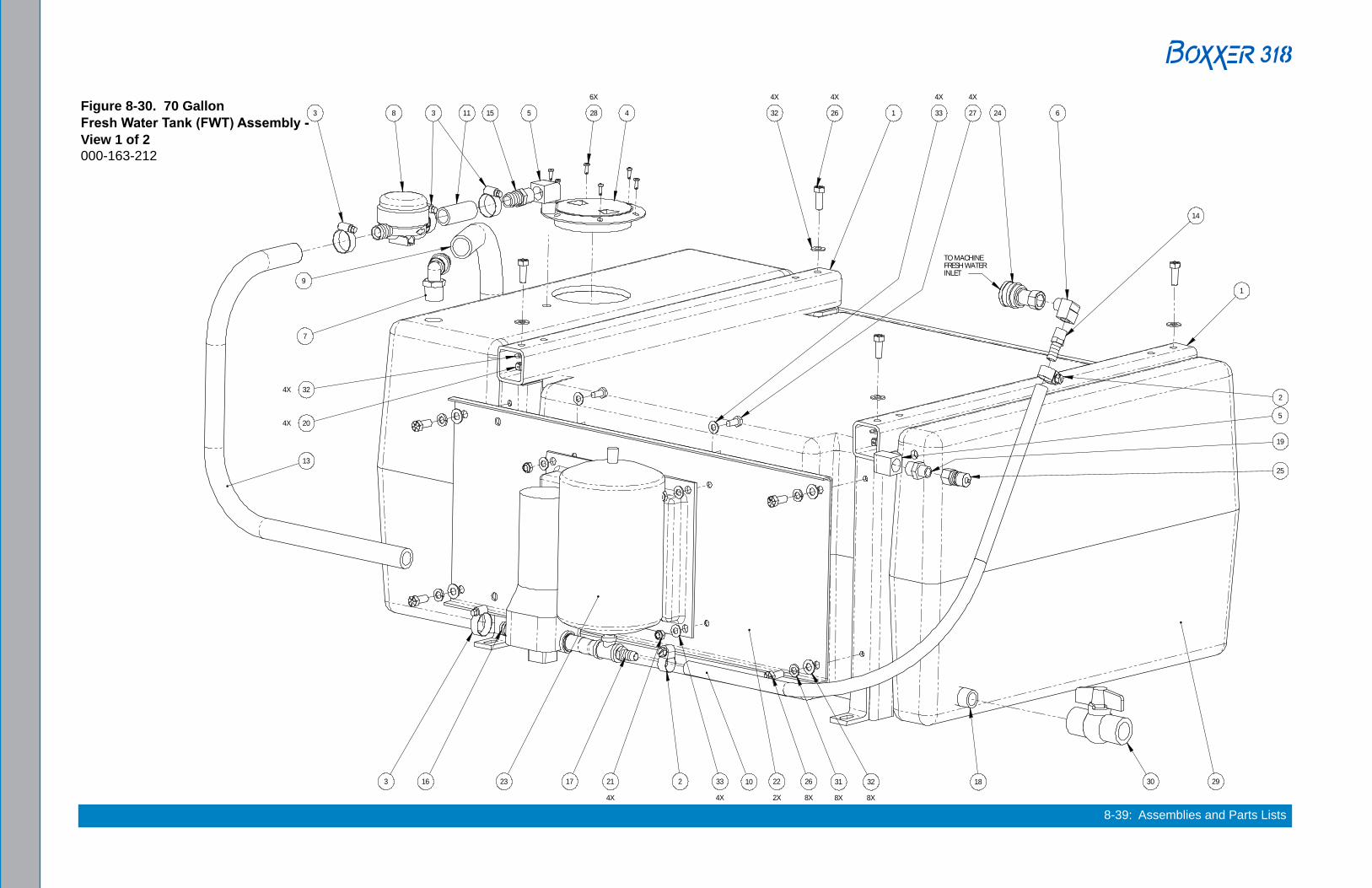
8-39: Assemblies and Parts Lists
Figure 8-30. 70 Gallon Fresh Water Tank (FWT) Assembly - View 1 of 2000-163-212
28
6X
451533
9
26
4X
32
4X
24 6
2930
14
2
5
19
25
23 2 10 26
8X
31
8X
32
8X
21
4X
33
4X
27
4X
33
4X
22
2X
324X
204X
1
1
TO MACHINE FRESH WATER INLET
18
7
8 11
13
17163

Assemblies and Parts Lists: 8-40
Figure 8-31. 70 Gallon Fresh Water Tank (FWT) Assembly View 2 of 2000-163-212
3
12
15

8-41: Assemblies and Parts Lists
70 Gallon Fresh Water Tank (FWT) Assembly Parts List
1 000-015-1238 Bracket, 70 FWT Mounting - Coated 2 2 000-033-004 Clamp, Size #6 Mini Hose 2 3 000-033-029 Clamp, Size #12 Hose 5 4 000-041-365 Cover, 4” Round 1 5 000-052-087 Elbow, 1/2” NPT Street 2 6 000-052-086 Elbow, 3/8” NPT Street 1 7 000-052-348 Elbow, 3/4” NPT X 1” Hose 1 8 - - - Filter, Flojet Pump (Comes w/ 000-111-170) 1 9 000-068-964 Hose, 1” I.D. Rubber X 36” Lg. - Red 1 10 000-068-975 Hose, 1/2” I.D. Rubber X 32” Lg. 1 11 000-068-973 Hose, 3/4” I.D. Rubber X 2.5” Lg. 1 12 000-068-965 Hose, 3/4” I.D. Rubber X 16” Lg. 1 13 000-068-974 Hose, 3/4” I.D. Rubber X 30” Lg. 1 14 000-052-105 Insert, #68 (3/8” NPT X 1/2” Barb) 1 15 000-052-129 Insert, #812, 1/2NPT X 3/4 Hose 2 16 - - - Insert, Flojet Pump Inlet (Comes w/ 000-111-170) 1 17 - - - Insert, Flojet Pump Outlet (Comes w/ 000-111-170) 1
Item Part Number Description Qty Item Part Number Description Qty
18 000-052-326 Nipple, 3/4” NPT Close 1 19 000-052-075 Nipple, 3/8” NPT X 1/2” NPT 1 20 000-094-015 Nut, 3/8”-16UNC Hex 2-Way Locking 4 21 000-094-038 Nut, 5/16”-18UNC Nylock 4 22 000-105-668 Plate, Side - Coated 2 23 000-111-170 Pump, Flojet w/ Bladder 40 psi Fresh Water 1 24 000-052-053 Quick Connect, 3/8 Female 1 25 000-052-052 Quick Connect, 660 3/8” Brass w/ EPDM O-Ring 1 26 000-143-018 Screw, 3/8”-16UNC X 1” Lg. Hex Head - Grade 8 12 27 000-143-012 Screw, 5/16”-18UNC X 3/4” Lg. 4 28 000-143-314 Screw, #8 X 1/2” Lg. Pan Head 6 29 000-159-182 Tank, 70 Gallon Fresh Water Rotomolded 1 30 000-169-202 Valve, 3/4” FPT Ball Valve 1 31 000-174-021 Washer, 3/8” Lock 8 32 000-174-005 Washer, 3/8” Flat 16 33 000-174-049 Washer, 5/16” Flat 8

Assemblies and Parts Lists: 8-42
Figure 8-32. Dura-Flow APO 90 Degree Assembly000-079-099 Rev. D
See Figure 8-1 for adhesive/sealant information.

8-43: Assemblies and Parts Lists
Dura-Flow APO 90 Degree Assembly Parts List
1 000-111-169 Assembly, APO Pump - Jabsco 1 2 000-012-011 Block, 6 Post Terminal 1 3 000-015-891 Bracket, APO Clamp - Fabricated 1 4 000-015-890 Bracket, Tank Mounted APO Support - Fabricated 1 5 000-033-022 Clamp, 1/2” Nylon Hose 1 6 000-037-048 Conn 2 Pole Female Water Tight 1 7 000-037-033 Conn 22 Pink Butt 2 8 000-052-724 Fitting, 1” NPT Cam Lock - Banjo 100B 1 9 000-052-723 Fitting, 1” NPT Cam Lock - Banjo 100F 1 10 000-052-725 Fitting, APO Bulkhead - Weldment 1 11 000-157-090 Float, Lever Switch 1 12 000-057-192 Gasket, APO Bulkhead 1 13 000-063-021 Harness, 1/4” Split Wire Loom 5Ft 14 000-052-654 Insert, #1612 (1” NPT X 3/4” Barb) 1 15 000-079-049 Kit, APO Connection 1 16 000-061-131 Knob, Handle - RDM 2 17 000-091-043 Motor Assembly - APO 1
Item Part Number Description Qty Item Part Number Description Qty
18 000-094-113 Nut, 1/4”-20UNC Neoprene Wellnut 8 19 000-094-027 Nut, #10-24UNC Hex 1 20 000-135-051 Regulator, 3 Amp 1000 PIV Diode 1 21 000-143-566 Screw, 1/4”-28UNF X 0.75” Lg. Socket Head 4 22 000-143-074 Screw, 1/4”-20UNC X 0.50” Lg. Hex Head Self-Tapping 4 23 000-143-002 Screw, 1/4”-20UNC X 1.00” Lg. Hex Head 8 24 000-143-310 Screw, 10-32 X 1/2” HXSLHD Self Tapping 1 25 000-143-532 Screw, #6-32UNC X 5/8” Lg. Socket Head 2 26 000-147-030 Seal Water Tight Wire Connector 2 27 000-157-022 Switch, Relay 1 28 000-037-022 Term 10 AWG Fully Insulated Female 3 29 000-037-012 Term Fully Insulated Female Q 1 30 000-037-050 Term Male Pin 4 Pole Water Tight 2 31 000-162-001 Tie, Wrap 4 Nylon 4 32 000-174-002 Washer, 1/4” Flat 4 33 000-174-060 Washer, 1/4” Rubber Backed 8 34 000-174-001 Washer, #10 Flat 1

Assemblies and Parts Lists: 8-44
Figure 8-33. APO Pump Assembly000-111-169 Rev. D
APO Pump Assembly Parts ListItem Part Number Description Qty
1 000-092-010 Mount, APO Pump Head - Coated 1 2 000-105-696 Plate S/S APO Inner Wear 1 3 000-105-697 Plate S/S APO Outer Wear 1 4 000-111-168 Pump, Jabsco 1
See Figure 8-1 for adhesive/sealant information.

8-45: Assemblies and Parts Lists
Figure 8-34. APO Connection Kit000-079-049 Rev C.
APO Connection Kit Assembly Parts ListItem Part Number Description Qty
1 000-015-720 Bracket, APO Outlet Mounting - Coated 1 2 000-027-014 Cap, Garden Hose 1 3 000-057-055 Gasket, Garden Hose 1 4 000-052-338 Insert, #1212 (3/4” NPT X 3/4” Barb) 1 5 000-052-281 Nipple, 3/4” NPT X 3/4” Male Garden Hose 1 6 000-094-009 Nut, 1/4”-20UNC Nylock 2 7 000-174-050 Washer, 1” Flat 1 8 000-174-063 Washer, 1.5” O.D. X 1.073” I.D. X 0.075” Thk. 1 9 000-174-003 Washer, 1/4” Flat 2

Assemblies and Parts Lists: 8-46
Hose Routings
Part No. Description Hose RoutingFrom To
000-068-104 Hose, 2.5” I.D. X 2.5” Lg. Silicone Blower Silencer000-068-104 Hose, 2.5” I.D. X 2.5” Lg. Silicone Silencer Lower Exhaust Elbow000-068-203 Hose, 3/16” I.D. X 34” Lg. Orifice Assembly Water Box000-068-517 Hose, 3/16” I.D. X 23” Lg. Chemical Metering Solution Out000-068-517 Hose, 3/16” I.D. X 23” Lg. Chemical Pump Prime000-068-518 Hose, 3/16” I.D. X 18.25” Lg. Pump Gauge000-068-587 Hose, 3/8” I.D. Throb X 17.5” Lg. By-Pass Valve Heat Exchanger000-068-627 Hose, 3/16” I.D. X 44” Lg. Orifice Assembly Rec Tank000-068-724 Hose, 5/16” I.D. X 18” Lg. Heat Exchanger Solution Out000-068-888 Hose, 3/16” I.D. X 24” Lg. Heat Exchanger Orifice Assembly000-068-967 Hose, 1/2” I.D. Rubber X 20” Lg. Water Box Drain000-068-968 Hose, 1/2” I.D. Rubber X 56” Lg Pump Water Box000-068-969 Hose, 1/2” I.D. Rubber X 69” Lg. Fresh Water In Water Box000-068-970 Hose, 3/4” I.D. Rubber X 50” Lg. Pump Water Box000-068-971 Hose, 3/8” I.D. Clear w/ Braid X 60” Lg. Chemical Pump Flow000-068-972 Hose, 3/8” I.D. Rubber X 76” Lg. Chemical Prime Recovery Tank000-068-977 Hose, 5/32” I.D. Vacuum X 82” Lg. Blower Vacuum Gauge000-068-978 Hose, 5/32” I.D. Vacuum X 52” Lg. Blower Lube Port000-068-979 Hose, 1/4” I.D. Fuel Low Perm X 120” Lg. Carburetor Fuel Hook Up000-068-980 Hose, 3/8” I.D. Clear w/ Braid X 28.5” Lg. Chemical Jug Flow

9-1: How to Order Parts
9 - How to Order PartsThis section describes how to obtain a proper diagnosis of any malfunctions, and how to order warranty replacement parts or repairs as outlined in the following areas:
� Warranty Parts Orders � Parts Orders � Emergencies
WARRANTY PARTS ORDERS1. Call the local distributor where you purchased your equipment and ask for the
Service Department.
2. Have the following information ready: a. Equipment Model b. Date of Purchase c. Hours on the Unit d. Unit Serial Number e. Description of Malfunction
3. Once it has been determined which parts are needed to correct the problem with your truckmount, make arrangements with your distributor to either perform the repairs or ship the parts to you.
We shall always endeavor to be fair in our evaluation of your warranty claim, and shall provide you with a complete analysis of our findings.
HydraMaster warranty covers only defective materials and/or workmanship for the periods listed. Diagnostic reimbursement is specifically excluded.
PARTS ORDERSCall your local distributor. In most instances, they either stock or have access to parts through a regional service center.
EMERGENCIESIf, for any reason, your distributor is unable to supply you with the necessary parts, they may call us and arrange for expedited shipping.
HydraMaster sells parts only through authorized distributors and service centers.

How to Order Parts: 9-2

10-1: Warranty Information
10 - Warranty InformationThis section lists causes of component failure that specifically void warranty coverage to avoid misunderstandings which might occur between truckmount owners and the manufacturer. Such causes as listed in this section shall constitute abuse or neglect.
The following topics are covered in this section
� Blower � High Pressure Water Pump � Recovery Tank � Chemical System � Control Panel � Vacuum and Solution Hoses � Cleaning Wand � Water Heating System � Hard Water Deposits � Warranty Procedure
BLOWER • Failure to lubricate the impellers daily with an oil based lubricant. • Failure to lubricate the bearings as recommended in the blower manual. • Failure to maintain the proper oil levels in the blower. • Failure to use the correct oil grade and viscosity as recommended in the blower
manual. • Failure to properly maintain blower safeguard systems such as waste tank filter screen,
vacuum safety relief valve and waste tank automatic shut-off system. • Allowing foam to pass through the blower.
HIGH PRESSURE WATER PUMP • Failure to maintain the proper oil level as recommended in the pump manual. • Failure to change the oil in the pump at recommended intervals. • Failure to protect the pump against freezing. • Failure to maintain the pump protection shut-off system. • Failure to use water softener in hard water areas. • Use of improper chemicals.

Warranty Information: 10-2
RECOVERY TANK • Failure to properly maintain the filtering devices in the tank. • Failure to clean the tank as recommended by manufacturer. • Failure to maintain the vacuum safety release in the tank. • Use of improper chemicals.
CHEMICAL SYSTEM • Use of improper chemicals. • Failure to use water softener in hard water area. • Operating truckmount without a proper chemical filter screen. • Failure to protect against freezing.
CONTROL PANEL • Failure to protect flowmeter and water pressure gauge against freezing.
VACUUM AND SOLUTION HOSES • Failure to protect the hoses against freezing. • Failure to protect the hoses against burns from the engine and blower exhaust. • Damage to the hoses from being run over by vehicles. • Kinking or cracking from failure to store or unroll the hoses correctly. • Normal wear and tear from everyday use.
CLEANING WAND • Failure to protect against freezing. • Obvious physical abuse of the wand.
WATER HEATING SYSTEM • Over-pressurization of the system (recommended maximum working
pressure-1,000 psi). • Failure to protect against freezing.
HARD WATER DEPOSITS • Failure to use or maintain a water softening system or a properly installed magnetic-
type descaler, whichever might be necessary, with truckmount’s operating in designated “Hard Water Areas” (3.0 grains or more per gallon).

10-3: Warranty Information
WARRANTY PROCEDUREWarranty coverage is available to you through your local distributor.
If you have moved to a new area or have purchased a used machine and need information regarding your local distributor, call HydraMaster at (800) 426-1301 or email us at:[email protected].
When calling your distributor, be sure to have the machine’s information; model and serial number, ready for the service representative.
FOR YOUR REFERENCE:
Model No. _____________________________________________________
Serial No. _____________________________________________________
Date of Purchase: ______________________________________________
Purchased From (Distributor): ____________________________________

Warranty Information: 10-4
CS-46247 Rev. A
11015 47th Ave. West Mukilteo, WA. 98275 www.hydramaster.com [email protected] Toll Free Phone: 800.426.1301 Local Phone: 425.775.7272 Fax: 425.771.7156
©2014 Nilfisk-Advance, Inc.
HYDRAMASTER® LIMITED WARRANTYHydraMaster warrants to the original end user, each new machine, new accessories and genuine replacement parts against defects inmaterial and workmanship under normal use and service. Our obligation under this warranty is limited to repair or replacement of the defective item at our factory or by an Authorized Service Center. Warranty coverage shall begin on the date of purchase by the original end user (as evidenced by your invoice from the factory or Authorized Dealer) or six (6) months from the date the machine was shipped from the factory, whichever is earlier. The warranty registration card must be completed and returned within 30 days of purchase. The warranty coverage period is specified below.
This warranty shall not apply to repairs resulting from accidents or misuse, damage in transit, overloading the capacity of the machine, failure due to lack of proper maintenance or care as described in the operating and maintenance instructions. Freezing of any water or chemical related component will VOID all warranties on water or chemical related components, internal or external. Corrosion, deposits and/or build-up in the water, chemical, recovery or heating systems due to hardness in the water used or chemicals which result in deposits, will VOID all warranties on affected components. The use or application of any chemical, including but not limited to acids or solvents, which results in damage to metal, rubber, plastic, or painted parts will VOID all warranties on those parts. Minor adjustments, such as tightening of screws or bolts not connected with the replacement of parts, are not covered. Replacement of expendable wear items including, but not limited to paint, labels and other cosmetic parts are also not covered. Repairs or alterations by an organization other than the factory or an Authorized Service Center are not covered and will void any HydraMaster warranty as to the parts or systems repaired or altered by a non-authorized organization.
THERE ARE NO WARRANTIES THAT EXTEND BEYOND THE DESCRIPTION OF THE LIMITED WARRANTIES STATED WITHIN. NO OTHER WARRANTY, EXPRESSED OR IMPLIED, INCLUDING BUT NOT LIMITED TO ANY IMPLIED WARRANTY OF MERCHANTABILITY OR FITNESS FOR A PARTICULAR PURPOSE, IS MADE EXCEPT AS EXPRESSLY STATED HEREIN. ANY STATUTORY IMPLIED WARRANTIES, INCLUDING ANY WARRANTY OF MERCHANTABILITY OR FITNESS FOR A PARTICULAR PURPOSE, THAT ARE IMPOSED BY LAW DESPITE THE EXPRESS LIMITATION OR WARRANTIES ABOVE, ARE EXPRESSLY LIMITED TO THE DURATION OF THE WRITTEN WARRANTY. BUYER UNDERSTANDS, ACKNOWLEDGES AND AGREES THAT THE REMEDIES PROVIDED UNDER THIS LIMITED WARRANTY ARE THE SOLE AND EXCLUSIVE REMEDIES AVAILABLE TO THE BUYER. HYDRAMASTER WILL NOT BE LIABLE FOR ANY OTHER OR ADDITIONAL DAMAGES, INCLUDING BUT NOT LIMITED TO INDIRECT, SPECIAL OR CONSEQUENTIAL DAMAGES ARISING OUT OF OR IN CONNECTION WITH THE FURNISHING, PERFORMANCE, USE OF OR INABILITY TO USE THE MACHINE. ANY EXTENSIONS OF OR MODIFICATIONS MADE TO THIS WARRANTY BY A DEALER/DISTRIBUTOR OF HYDRAMASTER ARE THE SOLE RESPONSIBILITY OF THE DEALER/DISTRIBUTOR.
HydraMaster will pay all freight and transportation charges within the United States, via normal ground shipping means, for replacement of parts covered under this warranty. All material must be properly authorized by HydraMaster prior to being returned. When returning, please provide an explanation of the problem and include the serial number of the machine as well as the name of the selling organization. All defective material must be returned to HydraMaster within 60 days of authorization. The Technical Service department of the authorized Dealer Service Center or the factory will investigate and then contact you.
Transportation of hazardous waste or contaminated equipment is subject to various laws and regulations. In returning machines, parts, or accessories under this limited warranty, the end user must certify in writing that the machines, parts or accessories being returned have not been used for handling, clean up, or disposal of hazardous waste or hazardous materials including but not limited to such things as asbestos, anthrax etc. or if the machines, parts or accessories being returned have been used for handling, clean up, or disposal of hazardous waste or hazardous materials, then the end user must have the machines, parts or accessories decontaminated by licensed and qualified decontamination professionals and provide written certification of this decontamination signed by the decontamination professionals. These machines, parts or accessories are to be returned only to the local HydraMaster Authorized Service Center for Warranty service along with decontamination certification.
HydraMaster reserves the right to change its warranty policy without notice.
HydraMaster is a Nilfisk-Advance, Inc. brand.
GROUP Parts1,2 Labor2
Frame 3 Years 2 Years Covers 3 Years 2 Years Vacuum Recovery Tank (Structural only) 3 Years 2 Years Vacuum Pump See Note 3 2 Years Chemical Systems 2 Years 2 Years Hoses, Internal Machine 2 Years 2 Years Hoses, External Machine 2 Years 2 Years Valve, High pressure bypass 2 Years 2 Years Water Heating System 2 Years 2 Years Pump, High pressure water See Note 3 2 Years Belts 2 Years 2 Years Fittings, internal machine 2 Years 2 Years Filter Screens 2 Years 2 Years Gauges 2 Years 2 Years Electrical Components 2 Years 2 Years Engine See Note 3 2 Years Accessories and Fresh Water Tanks 1 Year 1 Year Replacement Parts 4 90 Days NA
NOTES:1-Parts repaired or replaced are guaranteed for the remainder of the original machine warranty period. 2-Coverage only applicable to products sold and used in the United States and Canada. 3-As provided by the original Manufacturer. 4-Applies to replacement parts only after machine warranty coverage has expired.

11-1: Accessories and Chemical Solutions
11 - Accessories and Chemical Solutions
HydraMaster’s machine accessories are the most innovative collection available in the cleaning industry. For example, our RX-20® Rotary Extractors have changed the shape of carpet cleaning. In addition, our hoses, reels and tanks are of the finest quality construction.
Our carpet care and hard floor care chemical solutions have been specially prepared, not only to give you exceptional cleaning, but also to optimize your truckmount’s operation and reliability. HydraMaster’s chemical solutions will help maintain your machine’s water pump and water heating systems at peak efficiency and also help ensure fewer breakdowns.
HydraMaster’s full line of machine accessories and chemicals can enhance cleaning performance while reducing your labor costs, and include:
• Upholstery Tools• Wands • Vacuum Hoses• Tanks• Van Accessories• Hose Reels• Carpet Care Detergents• Rinse Agents• Pre-Sprays• Hard Floor Care Detergents• Defoamers and Descalers• Deodorizers and Disinfectants• Spotting Agents
For more information about our full line of accessories and chemical solutions, refer to the HydraMaster website at http://www.hydramaster.com.
To order genuine HydraMaster accessories and chemical solutions, call your nearest authorized HydraMaster Distributor.

Accessories and Chemical Solutions: 11-2