Embed Size (px)
Citation preview
1
Boxing Humanoid RobotJin Han Lee, Carlos Nieto, Michael Novitzky
Abstract—In 2008, Nao robots played soccer for the firsttime in Robocup in Suzhou, China. This robots are developedto play soccer and for entertainment (e.g. dancing, interactingwith children). This report presents that using different motionplanning methods (e.g. inverse kinematics, RRTs, potential fields),allows this robot to do more complicated tasks like boxing. Themain challenge is to deal with the constraints of the robot’shardware to accomplish fighting tasks such as punching as fasterthe robot can to his opponent.
Index Terms—motion planning, boxing, Nao robot.
I. INTRODUCTION
BOXING is one of the simplest and oldest combat sportswhere two participants fight each other with their fists
until one of them is knocked unconscious. Is supervised bya referee and is typically engaged in during a series of oneto three-minute intervals called rounds. Victory is achieved ifthe opponent is knocked down and unable to get up beforethe referee counts to ten seconds (a Knockout, or KO) or ifthe opponent is deemed too injured to continue (a TechnicalKnockout, or TKO). If there is no stoppage of the fight beforean agreed number of rounds, a winner is determined either bythe referee’s decision or by judges’ scorecards. [1]
Over the last years, In the last 6 years, fighting robotshas become one of the most popular activities for hobbyistroboticist in the world. This work addresses the problem tochange a robot designed to play soccer into a boxing robot.
A. Physics behind boxing: Contact with the Goal
The fist has its maximum velocity when it hits something[2].This collision causes the fist to slow down, and eventuallywhen the fighter begins applying a force to retract his arm, thefist stops and returns to the fighter. This speed is calculatedusing; V elocity = distance
time . As you can see, there are twoways to make a fist go faster:
1) By lengthening the distance or shortening the time. Thedistance can be lengthened to a maximum of the fighter’sarm length, but the time will depend on training, and theacceleration (acceleration = velocity
time ) of the arm.2) Calculating the momentum and impulse of the arm and
fist of the fighter where the momentum (P ) can be seenas an object’s tendency to resist change in accelerationP = m ∗ v. An impulse (I) is the change in momentumof a certain object.
I =∫
Fdt (1)
I =∫
dp (2)
College of ComputingSchool of Interactive ComputingGeorgia Institute of Technology
I = 4p (3)
B. Punch steps
1) Before the fist makes contact with the face, it has acertain momentum, and a stationary head would havezero momentum.
2) During the contact, there is a transfer of momentum fromthe fist and arm to the head of the opponent.
3) Although momentum is conserved when looking at bothboxers, just looking at the person taking hit, his/her mo-mentum has changed from zero, to what ever momentumwas transferred from the fist.
A faster punch can be more effective because with the mass ofthe fist being constant, by increasing velocity, the momentumthat the punch carries is larger, hence, but change in momen-tum that the opponent’s head experiences increases.
II. RELATED WORK
In [3], Moissec et al. proposed software that be used to gen-erate an optimal trajectory kicking motion for the Humanoidrobot HPR-2. Using a dynamic model of the robot incluidingstatic friction and the hardware constraints of the motors andthe reduction ratio, they calculate an optimal motion obtainedand some characteristics of the process of motion generation.
III. MOTION PLANNING FOR ROBOT BOXING
A. Collision Detection
Collision detection was performed by the V-COLLIDE:Accelerated Collision Detection for VRML library and imple-mented in the RST framework. With each iteration, the planneris given an object collision list. A function was designedto detect either a collision with the defending head or thedefending torso and one of either the attacking limb types,either the arm of the robot starting from the elbow to the tipor the leg consisting of the shin and foot.
B. Forward Kinematics
Forward kinematics was calculated using Mathematica foreach joint starting from the base of where each limb attachedto the torso. Thus, each arm began at the shoulder jointand each leg began at the hip joint. The forward kinematictransformation matrices were hard coded into the planner usingthe full simplify equations. The planner then only requiredthe current joint angle configuration in order to estimate thecurrent cartesian coordinates.
2
C. Inverse Kinematics
The inverse kinematics [4], [5]were calculated using anunderconstrained Jacobian method. Underconstrained becauseonly the cartesian location was calculated and not the ori-entation of the end effector. Utilizing Mathematica1, eachJacobian matrix was calculated by differentiating each x,yand z equation with respect to each joint from the forwardkinematic transformation matrices. The Jacobian matrix wasthen hard coded into the system and only required input ofthe angle configuration for each end effector to begin theinverse kinematics. Because of system limitations the psuedo-inverse was used calculated using Single Value Decompositionutilizing the GSL2 mathematics library.
It is known that this is not the most efficient method tocalculate the inverse Jacobian yet the researchers felt thatcontinuing progress into other domains for the planner was themost effecient use of the limited time. In order to minimizesingularities the end effectors were limited from reaching jointvalues that would cause problems by simply not executingthose joint commands. Additionally, if the inverse Jacobianmethod resulted in joint commands that went beyond theirlimits they were also ignored yet those commands that didnot violate joint limitations were allowed to pass. This ensuredthat forward progress continued and the end effector would notget stuck in a singularity and kept the system more realistic.The inverse kinematics were used for all of the motions of theNao humanoid.
The most basic implementation of our planner simplyrequired the end effector location, determined with forwardkinematics, and the target limb centroid such as the heador the torso. The planner would then iterate in small deltasin cartesian coordinates, 0.0005, in a straight line from endeffector start location to goal location until either the endeffector ran out of 5,000 iterations, or a collision betweenthe end effector and the target limb was detected.
xdiff = targetx − attackLimbx (4)
ydiff = targety − attackLimby (5)
zdiff = targetz − attackLimbz (6)
distance =√
xdiff2 + ydiff2 + zdiff2 (7)
4x = (xdiff/distance) ∗ jacobianStepSize (8)
4y = (ydiff/distance) ∗ jacobianStepSize (9)
4z = (zdiff/distance) ∗ jacobianStepSize (10)
1Wolfram Research, Inc., Mathematica, Version 6.1, Champaign, IL (2008).2The GNU Scientific Library (GSL) is a numerical library for C and C++
programmers. It is free software under the GNU General Public License.
D. Potential Fields
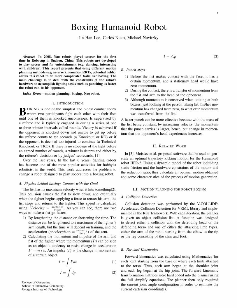
A goal of this project is to have an attacking robot scorepoints against a defending robot, obstacles were determined tobe the arms of the defending robot Thus, potential fields wereutilized for obstacle avoidance. This method allows the plannerto avoid a defender’s blocking arms. In order to simplify theproblem a potential field is created only using the XZ-plane(Figure 1) of the world using the Y value of the attacking endeffector to make a slice of the world.
Figure 1. 3D World Axis.
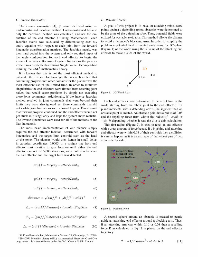
Each end effector was determined to be a 3D line in theworld starting from the elbow joint to the end effector. If aplane intersects with a defending arm’s line segment then anobstacle point is created. An obstacle point has a radius of 0.08and the repelling force from within the radius of −cosΘ or−sin Θ depending whether it was the z or x axis calculation.
This first radius (Figure 2), is used to repel an end effectorwith a great amount of force becuse if a blocking and attackingend effector were within 0.08 of their centroids then a collisionis sure to happen as it is an estimate of the widest part of twoarms side by side.
Figure 2. Potential Field
A second sphere around an obstacle is created to gentlyguide an attacking end effector around a blocking arm. Thus,if an attacking arm was within 0.10 or 0.08 then a repellingforce R as calculated in Eq 11 is placed on the end effectortrajectory.
R = −1/distance2 ∗ obstacleΘ (11)
3
As an attacking arm gets closer and closer to the defendingarm the repelling force grows more and more until it actuallymakes contact with the blocking arm and is repelled with agreat force. A target limb centroid is projected onto the XZ-plane regardless of its Y height in the world which means theend effector is constantly drawn to the target with a force ofcos(goalTheta) or sin(goalTheta).
4X =4Xobstacle +4Xgoal√
4X2 +4Z2(12)
4Z =4Zobstacle +4Zgoal√
4X2 +4Z2(13)
The 4Y is calculated exaclty the same as in the methodsabove for the straight line jacobian method. Thus, at each timestep, obstacle and goal points are created on an XZ-plane slice.The forces are summed as vectors and these x and z deltasare then input into the Jacobian to perform inverse kinematics.This allows an attacking robot limb to avoid a blocking armand still score a point.
E. Maximizing Impact of Punching
As one of our goal through this paper is to deliver possiblemaximum force to an opponent through maximizing momen-tum of a moving end effector at the contact to the opponent.Solutions generated from the previous section using IK aloneand IK with Potential Field contains too many waypoints dueto small jacobian step size ∆x. Executing such a solution failsto maximize the impact of motion on a target. In this section,we propose to meet the need of our goal a post processing steptaking two steps: extracting feature waypoints among manywaypoints and interpolating between feature waypoints.
Reducing the number of waypoints is important due to twomain factors. Firstly, it is not efficient for robot controllers tofollow fine grained waypoints. Controlling with high accuracyis costly expensive. Secondly, there is no much of space toincrease the momentum of the end effector. A controller shouldhandle a few waypoints along the path trajectory so that it canaccelerate the end effector by properly interpolating betweenwaypoints.
F. Extracting Feature Waypoints
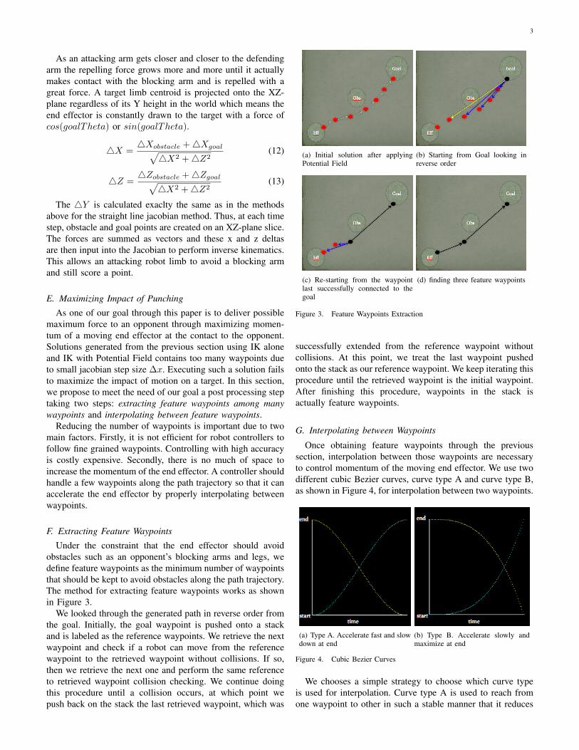
Under the constraint that the end effector should avoidobstacles such as an opponent’s blocking arms and legs, wedefine feature waypoints as the minimum number of waypointsthat should be kept to avoid obstacles along the path trajectory.The method for extracting feature waypoints works as shownin Figure 3.
We looked through the generated path in reverse order fromthe goal. Initially, the goal waypoint is pushed onto a stackand is labeled as the reference waypoints. We retrieve the nextwaypoint and check if a robot can move from the referencewaypoint to the retrieved waypoint without collisions. If so,then we retrieve the next one and perform the same referenceto retrieved waypoint collision checking. We continue doingthis procedure until a collision occurs, at which point wepush back on the stack the last retrieved waypoint, which was
(a) Initial solution after applyingPotential Field
(b) Starting from Goal looking inreverse order
(c) Re-starting from the waypointlast successfully connected to thegoal
(d) finding three feature waypoints
Figure 3. Feature Waypoints Extraction
successfully extended from the reference waypoint withoutcollisions. At this point, we treat the last waypoint pushedonto the stack as our reference waypoint. We keep iterating thisprocedure until the retrieved waypoint is the initial waypoint.After finishing this procedure, waypoints in the stack isactually feature waypoints.
G. Interpolating between Waypoints
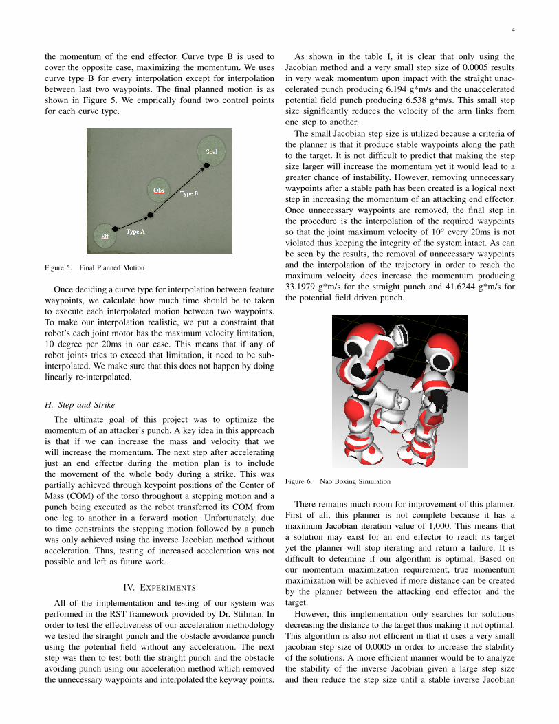
Once obtaining feature waypoints through the previoussection, interpolation between those waypoints are necessaryto control momentum of the moving end effector. We use twodifferent cubic Bezier curves, curve type A and curve type B,as shown in Figure 4, for interpolation between two waypoints.
(a) Type A. Accelerate fast and slowdown at end
(b) Type B. Accelerate slowly andmaximize at end
Figure 4. Cubic Bezier Curves
We chooses a simple strategy to choose which curve typeis used for interpolation. Curve type A is used to reach fromone waypoint to other in such a stable manner that it reduces
4
the momentum of the end effector. Curve type B is used tocover the opposite case, maximizing the momentum. We usescurve type B for every interpolation except for interpolationbetween last two waypoints. The final planned motion is asshown in Figure 5. We emprically found two control pointsfor each curve type.
Figure 5. Final Planned Motion
Once deciding a curve type for interpolation between featurewaypoints, we calculate how much time should be to takento execute each interpolated motion between two waypoints.To make our interpolation realistic, we put a constraint thatrobot’s each joint motor has the maximum velocity limitation,10 degree per 20ms in our case. This means that if any ofrobot joints tries to exceed that limitation, it need to be sub-interpolated. We make sure that this does not happen by doinglinearly re-interpolated.
H. Step and Strike
The ultimate goal of this project was to optimize themomentum of an attacker’s punch. A key idea in this approachis that if we can increase the mass and velocity that wewill increase the momentum. The next step after acceleratingjust an end effector during the motion plan is to includethe movement of the whole body during a strike. This waspartially achieved through keypoint positions of the Center ofMass (COM) of the torso throughout a stepping motion and apunch being executed as the robot transferred its COM fromone leg to another in a forward motion. Unfortunately, dueto time constraints the stepping motion followed by a punchwas only achieved using the inverse Jacobian method withoutacceleration. Thus, testing of increased acceleration was notpossible and left as future work.
IV. EXPERIMENTS
All of the implementation and testing of our system wasperformed in the RST framework provided by Dr. Stilman. Inorder to test the effectiveness of our acceleration methodologywe tested the straight punch and the obstacle avoidance punchusing the potential field without any acceleration. The nextstep was then to test both the straight punch and the obstacleavoiding punch using our acceleration method which removedthe unnecessary waypoints and interpolated the keyway points.
As shown in the table I, it is clear that only using theJacobian method and a very small step size of 0.0005 resultsin very weak momentum upon impact with the straight unac-celerated punch producing 6.194 g*m/s and the unacceleratedpotential field punch producing 6.538 g*m/s. This small stepsize significantly reduces the velocity of the arm links fromone step to another.
The small Jacobian step size is utilized because a criteria ofthe planner is that it produce stable waypoints along the pathto the target. It is not difficult to predict that making the stepsize larger will increase the momentum yet it would lead to agreater chance of instability. However, removing unnecessarywaypoints after a stable path has been created is a logical nextstep in increasing the momentum of an attacking end effector.Once unnecessary waypoints are removed, the final step inthe procedure is the interpolation of the required waypointsso that the joint maximum velocity of 10o every 20ms is notviolated thus keeping the integrity of the system intact. As canbe seen by the results, the removal of unnecessary waypointsand the interpolation of the trajectory in order to reach themaximum velocity does increase the momentum producing33.1979 g*m/s for the straight punch and 41.6244 g*m/s forthe potential field driven punch.
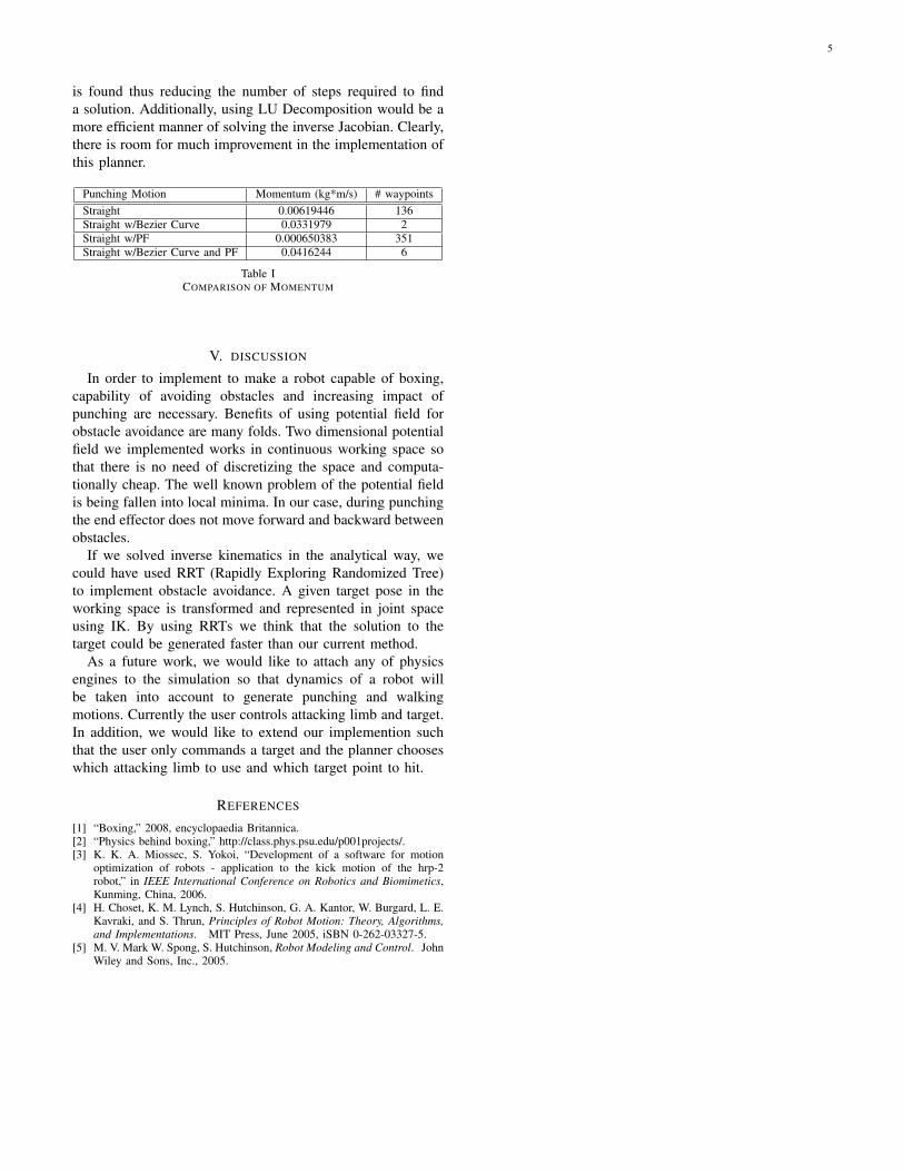
Figure 6. Nao Boxing Simulation
There remains much room for improvement of this planner.First of all, this planner is not complete because it has amaximum Jacobian iteration value of 1,000. This means thata solution may exist for an end effector to reach its targetyet the planner will stop iterating and return a failure. It isdifficult to determine if our algorithm is optimal. Based onour momentum maximization requirement, true momentummaximization will be achieved if more distance can be createdby the planner between the attacking end effector and thetarget.
However, this implementation only searches for solutionsdecreasing the distance to the target thus making it not optimal.This algorithm is also not efficient in that it uses a very smalljacobian step size of 0.0005 in order to increase the stabilityof the solutions. A more efficient manner would be to analyzethe stability of the inverse Jacobian given a large step sizeand then reduce the step size until a stable inverse Jacobian
5
is found thus reducing the number of steps required to finda solution. Additionally, using LU Decomposition would be amore efficient manner of solving the inverse Jacobian. Clearly,there is room for much improvement in the implementation ofthis planner.
Punching Motion Momentum (kg*m/s) # waypointsStraight 0.00619446 136Straight w/Bezier Curve 0.0331979 2Straight w/PF 0.000650383 351Straight w/Bezier Curve and PF 0.0416244 6
Table ICOMPARISON OF MOMENTUM
V. DISCUSSION
In order to implement to make a robot capable of boxing,capability of avoiding obstacles and increasing impact ofpunching are necessary. Benefits of using potential field forobstacle avoidance are many folds. Two dimensional potentialfield we implemented works in continuous working space sothat there is no need of discretizing the space and computa-tionally cheap. The well known problem of the potential fieldis being fallen into local minima. In our case, during punchingthe end effector does not move forward and backward betweenobstacles.
If we solved inverse kinematics in the analytical way, wecould have used RRT (Rapidly Exploring Randomized Tree)to implement obstacle avoidance. A given target pose in theworking space is transformed and represented in joint spaceusing IK. By using RRTs we think that the solution to thetarget could be generated faster than our current method.
As a future work, we would like to attach any of physicsengines to the simulation so that dynamics of a robot willbe taken into account to generate punching and walkingmotions. Currently the user controls attacking limb and target.In addition, we would like to extend our implemention suchthat the user only commands a target and the planner chooseswhich attacking limb to use and which target point to hit.
REFERENCES
[1] “Boxing,” 2008, encyclopaedia Britannica.[2] “Physics behind boxing,” http://class.phys.psu.edu/p001projects/.[3] K. K. A. Miossec, S. Yokoi, “Development of a software for motion
optimization of robots - application to the kick motion of the hrp-2robot,” in IEEE International Conference on Robotics and Biomimetics,Kunming, China, 2006.
[4] H. Choset, K. M. Lynch, S. Hutchinson, G. A. Kantor, W. Burgard, L. E.Kavraki, and S. Thrun, Principles of Robot Motion: Theory, Algorithms,and Implementations. MIT Press, June 2005, iSBN 0-262-03327-5.
[5] M. V. Mark W. Spong, S. Hutchinson, Robot Modeling and Control. JohnWiley and Sons, Inc., 2005.