Embed Size (px)
Citation preview

Bounded-distortion Piecewise Mesh Parameterization
Olga Sorkine Daniel Cohen-Or Rony Goldenthal Dani Lischinski
School of Computer Science School of Engineering & Computer ScienceTel-Aviv University The Hebrew University of Jerusalem
���
���
���
���
Figure 1: A pepper model flattened into one large piece with bounded distortion. The 3D object is shown on the left with a checkerboard texture demonstrating the low distortionof the parameterization. Seams introduced by our algorithm are shown in red. The middle image shows the flattened surface, visualizing the amount of distortion introduced by themapping across the mesh. A small region of the flattened mesh is shown on the right.
Abstract
Many computer graphics operations, such as texture mapping, 3Dpainting, remeshing, mesh compression, and digital geometry pro-cessing, require finding a low-distortion parameterization for ir-regular connectivity triangulations of arbitrary genus 2-manifolds.This paper presents a simple and fast method for computing pa-rameterizations with strictly bounded distortion. The new methodoperates by flattening the mesh onto a region of the 2D plane. Tocomply with the distortion bound, the mesh is automatically cutand partitioned on-the-fly. The method guarantees avoiding globaland local self-intersections, while attempting to minimize the totallength of the introduced seams.
To our knowledge, this is the first method to compute the meshpartitioning and the parameterization simultaneously and entirelyautomatically, while providing guaranteed distortion bounds. Ourresults on a variety of objects demonstrate that the method is fastenough to work with large complex irregular meshes in interactiveapplications.
Additional Keywords: atlas, mesh partitioning, parameterization,surface flattening, texture mapping, 3D painting
1 Introduction
Low-distortion parameterization of triangulated surfaces is a funda-mental problem in computer graphics. Such parameterizations areessential for operations such as texture mapping [1, 6, 9, 11, 14, 21],texture synthesis on surfaces [17, 19, 20], interactive 3D painting[7], remeshing and multi-resolution analysis [2, 8, 18], mesh com-pression [4, 16], and digital geometry processing [5]. Since in 3Dcomputer graphics surfaces are 2D entities (2-manifolds) embeddedin 3D space, a parameterization defines a mapping between regions
on the 2D plane and the surface, enabling these operations to beperformed almost as easily as if the surface was flat.
The surfaces used in computer graphics are very often piecewise-linear manifolds, represented as triangular meshes with irregularconnectivity and non-uniform triangle sizes. A parameterization ofsuch a surface may be defined by a mapping between its verticesand a set of points in the plane, such that the connectivity of themesh induces a planar triangulation. Of course, this is only possiblefor an open surface (with the topology of a disk). A closed surfaceof genus zero, such as a sphere, must be first cut open along at leastone edge before it can be mapped onto a planar region. Surfaces ofhigher genus require a larger number of cuts.
Ideally, the mapping between the triangulated surface and theplanar triangulation should be an isometry, preserving angles anddistances. Such a parameterization is area-preserving, so it is op-timal for texture mapping, remeshing, and digital geometry pro-cessing, since a regular sampling grid with uniform spacing in theparameter domain is undistorted by the mapping onto the surface.Unfortunately, with the exception of developable surfaces, such as acylinder, general open manifolds cannot be flattened without distor-tion. This distortion is particularly severe when flattening a highlycurved surface in one piece.
Distortion can be reduced by introducing additional cuts (seams)beyond those necessary to make the surface a topological disk. Thedownside of having too many seams, however, is that they intro-duce discontinuities into the parameterization. These discontinu-ities must be explicitly dealt with by the application, which typi-cally slows it down and sometimes results in visible artifacts. Thus,we are faced with two conflicting goals: reducing distortion on theone hand and keeping the seams few and short on the other hand. Toachieve our goals, it is usually necessary to split the mesh into sev-eral disconnected parts, even though it is already a topological disk.This partitioning results in a piecewise parameterization; the partsare sometimes referred to as charts and their collection is referredto as an atlas [11].
In this paper, we propose a simple and fast method for construct-ing piecewise parameterizations of irregular triangle meshes. Ourapproach is guided by two principles: (i) the distortion bounds arecontrolled, and the method guarantees that the distortion of eachmesh triangle does not exceed some preset threshold; (ii) the meshis cut and partitioned simultaneously with the construction of the

parameterization, and not as a preprocess, to the degree necessaryfor creating patches with bounded local distortion. Starting froma seed triangle each patch is “grown” incrementally, from the in-side outward, which allows control over local distortion and alsoprovides a convenient way to check for self-intersections. In eachstep a new vertex is chosen for flattening, from among the neigh-bors of already flattened vertices. The vertex selection criteria mayinclude various attributes, such as the distortion caused to the tri-angles sharing this vertex, local curvature, ratio of patch boundarylength to its area, etc. When there are no more vertices that fit thecriteria, the patch growth is stopped and a new patch is started. Fig-ure 1 demonstrates the result of applying our method to a model ofa pepper.
The proposed scheme has several advantages. First, it guaranteesa user-specified upper bound on the local distortion. Experimentsshow that in practice the average distortion value achieved is signif-icantly smaller than the specified bound. Second, the algorithm isfully automatic, partitioning the mesh as necessary in order to com-ply with the specified distortion bounds. It is guaranteed to producea valid parameterization without local or global foldovers. Finally,in contrast to most previous parameterization techniques, our algo-rithm is fast enough to enable working with large complex irregularmeshes in interactive applications. However, our approach does notprovide the optimal solution, it is greedy and provides no explicitcontrol on the location or the length of the seams.
The rest of the paper is organized as follows. In Section 2 wereview related work. Our algorithm is described in detail in Sec-tion 3. Section 4 presents some results and applications of ourmethod. Section 5 concludes the paper and suggests some topicsfor future work.
2 Previous Work
Many researchers have addressed the problem of computing low-distortion parameterizations for general surfaces, mainly for texturemapping purposes. We shall briefly survey some of their methodsbelow. For the most part, these earlier works concentrate on min-imizing the parameterization distortion and not on the mesh par-titioning problem. They either assume that the mesh has alreadybeen partitioned, or begin by computing a partitioning of the meshas a pre-process, based on some heuristic or interactive user input.Each part is then parameterized while minimizing some distortioncriterion. It should be noted that while several authors refer to theirtechniques as “non-distorting”, the resulting parameterizations typ-ically correspond only to a local minimum with respect to the cho-sen distortion measure, and do not guarantee any strict bounds onthe distortion. In contrast, our method computes the partitioning ofthe mesh simultaneously with surface flattening, introducing seamsand cuts only as necessary to produce a mapping with distortionstrictly below a specified bound.
Maillot et al. [11] partition the mesh into regions by bucketingfaces based on their normals, followed by merging together adja-cent buckets with similar normals and directions of maximal cur-vature. Each region is then flattened and the resulting parameteri-zation is improved by numerically minimizing a distortion energyfunctional. Eck et al. [2] and Lee et al. [8] implicitly partition themesh by using mesh simplification to construct a coarse base mesh.Each base mesh triangle defines a separate parameter domain for acorresponding cluster of triangles in the original mesh. The embed-ding is computed using harmonic maps ([8] add a subdivision-basedsmoothing step). Sander et al. [13] begin by partitioning the meshinto relatively flat regions (similarly to [11]). They define their own“geometric stretch” measure, and employ relaxation to minimize it.
All of the methods above may partition complex surfaces intomore parts than necessary to obtain a low-distortion parameteriza-tion, and, as already mentioned earlier, none of them provides strict
bounds on the distorion.Floater [3] embeds an open mesh in the plane by mapping its
boundary vertices to those of a predefined convex 2D polygon. Theposition of each inner vertex is then defined as a convex combina-tion of its topological neighbors, where the weights are set to mimicthe cord lengths and the angles between the edges emanating fromthe vertex. These constraints define a linear system of equationswhose solution provably exists, always yielding a valid planar map.However, the predefined planar boundary used by this method mayyield significant distortions in the resulting parameterizations, whenthe parameterized surface is complex and exhibits high curvatures.
Levy and Mallet [9] extend Floater’s approach by defining a setof non-linear constraints on the mapping that ensures local orthog-onality and even spacing of isoparametric curves. The non-linearsystem can be reduced to a set of linear systems by fixing one ofthe two coordinates in the plane and solving a linear optimizationproblem for the other. Their method also allows to interactivelyspecify “important” regions on the surface, which have higher pri-ority and are less distorted in the parameterization.
Haker et al. [6] propose an interesting method to embed a closedsurface onto a sphere by computing a conformal mapping whichpreserves angles of the mesh triangles. Another work by Shefferand de Sturler [15] also concentrates on preserving angles of themesh while mapping it onto the 2D plane. The mapping is de-fined in terms of the angles only, and an optimal solution is provento exist. However, these methods still impose high distortion onhighly curved surfaces and may cause global self-intersections. Tocope with the distortion problem, Sheffer [14] proposes to intro-duce seams into the surface, computed by a minimal-spanning-treealgorithm. Since cutting the surface at the regions of high curvaturereduces the Gaussian curvature, the seams improve the quality ofthe mapping. The self-intersections are detected in a post-process,and the parameterization needs to be recomputed to eliminate them,adding to the computational cost of the solution.
A recent work by Zigelman et al. [21] analytically finds an em-bedding of an open mesh in the plane by a multi-dimensional scal-ing (MDS) method that optimally preserves the geodesic distancesbetween mesh vertices. As in [9, 15], this approach does not requireforcing the mapping of the surface boundary, which allows betterparameterizations to be generated. Like other global optimization-based techniques, this method is computationally expensive anddoes not guarantee self intersections.
Bennis et al. [1] propose a piecewise flattening method for free-form parametric surfaces (such as B-spline patches). First, a user-specified isoparametric curve on the surface is embedded in theplane with geodesic curvature preservation. Next, their methodproceeds to iteratively unfold neighboring curves, until a distortionthreshold (involving cord length and angle distortion) is reached.The user selects the next curve on the remaining part of the surface,and the process repeats itself. To our knowledge this is the onlytechnique so far to produce a bounded distortion parameterization.Our approach is similar to that of Bennis et al. [1] in the sense thatwe also grow our patches incrementally until no more vertices canbe added. However, our method is fully automatic requiring no in-teractive user input, can handle any triangular mesh, and employsmore diverse stopping criteria (see Section 3.4). Another differenceis that we measure distortion in a different way that is better suitedfor triangular meshes, as in [13].
There are also several methods which specifically address theproblem of mesh partitioning or segmentation. Mangan andWhitaker [12] extend the watershed algorithm for image decom-position to handle polyhedral surfaces. Li et al. [10] use skele-tonization and space sweeping to decompose a given mesh intotopologically and geometrically homogeneous components. Sincethese segmentation methods are driven by other applications, suchas shape-based retrieval, hierarchical object representation, morph-

(a) (b)
Figure 2: Flattening of a cylindrical model. In (a), the parameterization createdby our algorithm is visualized. The seam line is marked in red. In (b) we show thatpartitioning such a mesh using normal-based bucketing [11] results in sixteen patches.
ing, etc., they are not particularly suited for parameterization. Forinstance, they do not necessarily produce topological disk patches,which is a basic requirement for a global flattening algorithm. Incontrast, our method partitions the mesh while computing the pa-rameterization, so the partitioning is driven by the specific goal ofproducing a bounded-distortion parameterization. Our method aimsat defining large patches whenever possible. For example, the sur-face of the model shown in Figure 2 is developable and is flattenedinto a single patch by our method, while partitioning the mesh usingnormal-based bucketing [11] results in sixteen patches.
3 Bounded Distortion Flattening
In this section, we describe our parameterization algorithm. Webegin with a brief overview of the proposed framework and thenelaborate on its different components.
3.1 Overview
Our algorithm is an iterative procedure that incrementally flattensthe mesh surface by growing patches around seed triangles, untilsome termination criterion is reached. We define as active an edgeseparating between a triangle that has already been added to thepatch (flattened) and one that hasn’t. The collection of all activeedges of a patch at any given moment is referred to as the patchfront. Our algorithm grows patches by iteratively selecting a newvertex adjacent to the patch front and adding it to the patch.
The above process explicitly makes sure that none of the trian-gles are distorted above the specified threshold. The first triangle ofa patch, referred to as the seed triangle, is randomly selected andembedded on a plane without any distortion. Its three edges definethe initial patch front. In each subsequent iteration, the algorithmexamines all the triangles adjacent to the front. Each such trianglehas two vertices that have already been mapped onto the plane, andone free vertex. We choose the “best” vertex among all free verticesadjacent to the front, and unfold it onto the plane along with the tri-angles incident to it and sharing an edge with the patch front. Theranking of the free vertices is determined based on several crite-ria (see Section 3.4), the most important of which is the distortion.More specifically, a vertex can be embedded only if the distortioncaused to each of the newly-flattened triangles does not exceed thepredefined threshold. The added triangles are also checked for in-tersections with the planar patch (see Section 3.5), and if an inter-section is detected, the vertex is discarded from the current patch.When no more vertices can be added to the current patch (eitherdue to distortion or intersections), the algorithm selects a new seedand starts growing a new patch.
For efficiency, the grades of the free vertices are kept in a priorityqueue. At each step we take the vertex with the highest grade offthe queue and map it onto the plane (Section 3.3). We then computethe grades of all free neighbors of the newly-added vertex and add
them into the priority queue. In addition, we update the grades ofthe free vertices adjacent to the flattened vertex, which are alreadypresent in the priority queue (Section 3.4).
3.2 The Distortion Metric
We measure the distortion caused to a triangle using the singularvalues of the Jacobian of the affine transformation between the orig-inal 3D triangle and its counterpart in the plane. The derivationbelow closely follows that of Sander et al. [13].
Let T = ∆q1q2q3 be the triangle in 3D and T 0 = ∆p1p2p3the triangle in 2D, where pi = (si;ti). Let S : R2 ! R3 be the(uniquely defined) affine mapping, such that S(pi) = qi. Denoteby hp1;p2;p3i= ((s2� s1)(t3� t1)� (s3� s1)(t2� t1))=2 the areaof ∆p1p2p3. Then, S is given by
S(p) =hp;p2;p3iq1 + hp;p3;p1iq2 + hp;p1;p2iq3
hp1;p2;p3i;
and the partial derivatives of S are:
Ss =∂S∂ s
=q1(t2� t3)+q2(t3� t1)+q3(t1� t2)
2 hp1;p2;p3i
St =∂S∂ t
=q1(s3� s2)+q2(s1� s3)+q3(s2� s1)
2 hp1;p2;p3i:
The singular values of the 3�2 Jacobian matrix [Ss St ] are:
γmax =
r12
�(a+ c)+
p(a� c)2 +4b2
�
γmin =
r12
�(a+ c)�
p(a� c)2 +4b2
�;
where a = Ss �Ss; b = Ss �St ; c = St �St .The values γmax and γmin represent the largest and the smallest
scaling caused to a unit length on the plane by the mapping S.Sander et al. [13] take the root-mean-square of the two values asthe L2 metric and γmax as the L∞ metric. Since for the purpose ofmeasuring geometric distortion, stretching and shrinking should betreated the same, we use the following expression as our distortionmetric:
D�T;T 0
�= max
�γmax; 1=γmin
:
Note that D(T;T 0)� 1, and the equality holds if and only if T andT 0 are isometric.
3.3 Embedding a Single Vertex
As stated above, in each step of the flattening procedure, we at-tempt to embed a free vertex V that is adjacent to the front. LetT1;T2; : : :;Tk be the triangles incident to V that share an edge withthe front (thus, V is their top vertex, see Figure 3(a)). We would liketo map V to a point v in the plane, so as to minimize the maximaldistortion caused to the triangles Ti. The optimal position v is foundusing a local relaxation technique. A faster alternative that performswell is to compute k candidate positions in the plane, each obtainedby rigidly unfolding each of the triangles Ti separately. The point vis then obtained as the weighted average of the candidate positions,where the weights are proportional to the distortion associated withthe flattened neighbors of the triangles (Figure 3(b–c)). Note thatexcept for certain degenerate cases, this choice of mapping preventstriangle-flipping. We check global and local self-intersections whenthe vertex is chosen to be added to the patch.

(a) (b) (c)
Figure 3: Embedding a vertex V . In (a), the patch on the 3D surface is shown in dark green and the red vertex is V , the top vertex of the triangles T1 and T2 that share an edgewith the patch front. In (b), the flattened patch is shown, with the triangles T1 and T2 unfolded separately into t1 and t2. Two planar positions for V are obtained: v1 and v2. In (c), v1
and v2 are unified into v, and the vertex is added to the patch.
In this embedding strategy each vertex has only one mapping tothe plane, simply because once a vertex is added to the patch, it can-not be flattened again in a different location. However, sometimesthe parameterization can benefit from forcing cuts in the surface,where the vertices on the cuts have two or more mappings to theplane. For example, if a cylinder is cut along the direction of itscentral axis, it can be unfolded to the plane in one piece (see Figure2(a)). To detect such cases, once the patch growth is complete, wetraverse the front and look for adjacent unmapped triangles whosetop vertices are already mapped in some other regions of the patch.These triangles can be added to the patch by assigning a secondlocation to their top vertex (thus introducing a seam).
3.4 Local Criteria for Vertex Embedding
As explained in Section 3.1, we assign a grade to each free vertexadjacent to the patch front, and select the vertex with the highestgrade at each iteration. The grade is a non-negative real number,comprising various factors with different importance weights. Themain factor is the maximal distortion caused to the triangles adja-cent to the vertex. If this value is above the predefined threshold,the vertex is given a grade of zero, and thus cannot be flattened.
Another important issue is the boundary length of the resultingpartition. We would like to keep it as small as possible and preventthe creation of thin long patches (strips). This may be done bybounding the ratio between the area of the patch and the squaredlength of the boundary. Vertices that increase this ratio are given alower grade, and thus the algorithm strives to grow round patcheswith smooth boundaries. This ratio can also be incorporated as astopping condition: when adding any vertex to the patch resultsin an area/perimeter ratio greater than some threshold, the patchgrowth is stopped.
Additional criteria that can be involved in the grade calculationare crease angles or ridge lines on the surface and other segmen-tation information that may be available. The weight of each fea-ture should be determined by the specific application that uses theparameterization. For instance, in texture mapping, visible seamsbetween the patches are an undesirable artifact, and therefore min-imizing the boundary length should be given more weight. For a3D painting application, the most critical factor is low and homo-geneous distortion of the parameterization, while seams can be tol-erated.
Note that the grade given to a vertex can change during the pro-cess of patch growing. Figure 4 illustrates a situation where thevertex V is given an initial grade based on the two triangles that areincident to it. But after embedding another vertex, an additional tri-angle becomes incident to V , and thus the position of V on the planeis altered and the grade of V must be recomputed. Grades changesare local, since embedding a vertex can affect only its topologicalneighbors. By Euler’s formula, the average valence of a vertex issix. Thus on average up to six grades are recomputed each time a
(a)
(b)
Figure 4: Change of a vertex grade. In (a), the vertex V has two incident trianglesT1 and T2, and its plane position and grade is calculated based on these two triangles.In (b), the vertex U is added to the patch, and as a result, the triangle T3 also becomesincident to V , so that the grade of V must be updated.
vertex is added to the patch, but in practice grade changes are muchmore rare.
3.5 Preventing Self-intersections
There are two types of self-intersections that must be prevented:local and global ones. A local self-intersection, also called face-flipping, occurs when the triangle newly added to the patch, “foldsover” the patch, and the cyclic order of its vertices is reversed withrespect to the original 3D triangle. Such triangles are sometimesreferred to as having a negative area, and global relaxation tech-niques (e.g., [9, 11, 13]) use high penalties to prevent this kind ofself-intersection. In our algorithm, we take care of triangle flippingby ensuring that the position of the top vertex of each added triangleis located locally “outside” the patch, as shown in Figure 5.
Global self-intersections occur when distant parts of the patchcross each other. This type of self-intersection is much harderto track in global embedding techniques and usually it is not ad-dressed. In fact, it can only be detected in a post-process, as doneby Sheffer and de Sturler [15]. In our algorithm, since the flattenedpatch is grown incrementally, we can make sure that each addedtriangle does not cross the rest of the patch. It is enough to merelytest for intersection with the boundary of the patch, since the patchis simply-connected, and each added triangle has a common edgewith the boundary. To efficiently perform this test, we insert theboundary triangles of the flattened patch into a spatial partitioningdata structure. In the current implementation, we use a regular gridpartition, which allows us to locate the boundary triangles that can

potentially intersect the new triangle in near-constant time.
Figure 5: Checking local self-intersections and preventing triangle flipping. Thevertex v is incident on two triangles, whose neighbors in the patch are t1 and t2. Thehalf-planes Π1 and Π2 are bounded by lines that support the bases of t1 and t2, respec-tively. Local self-intersection is prevented by ensuring that v 2 Π1 \Π1.
4 Results and Applications
We have implemented our algorithm in C++ and tested it on a vari-ety of 3D meshes. Various statistics pertaining to the different testsare summarized in Table 1.
Although our code has not been optimized, the running timesare rather small when using the fast approximation of optimal ver-tex position (described in Section 3.3). Large models, such as the100K triangle Venus, or the 40K triangle Horse (both shown in Fig-ure 12), are flattened in 9 and 5 seconds, respectively The 1300triangle Lamp model is flattened in less than a second. All timeswere measured on a 1.0 GHz Pentium III CPU.
Figure 12 shows the three models above with a checkerboard tex-ture map in order to visualize the quality of the parameterizations:it can be seen that the checkerboard pattern is not visibly distortedby the mapping. Each patch is shaded using a different color in or-der to visualize the partitioning performed by our method in orderto achieve this low-distortion parameterization. Table 1 reports thedistortion bound given to our algorithm along with the actual meandistorion value achieved in each case (weighted by the areas of thetriangles in 3D). The table also reports the seam length (divided bythe sum of the edge lengths in the mesh) and the running times.
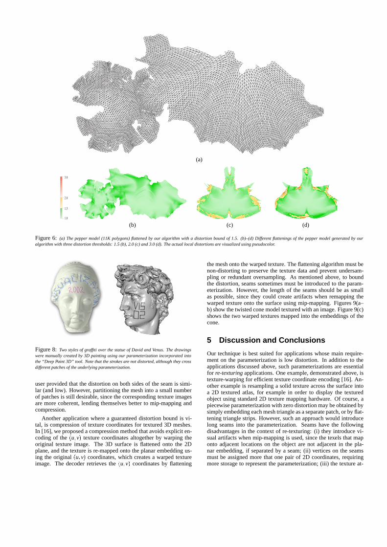
Figure 6(a) shows the result of flattening the pepper model(11K polygons). Our algorithm embeds the surface into a sin-gle patch when given a distortion threshold greater than 1.5. Fig-ure 6(b–d) shows three different embeddings, corresponding fromdistortion thresholds of 1.5, 2.0 and 3.0, respectively.
For comparison, we have also implemented a normal-basedbucketing partitioning scheme, which partitions the surface intopatches consisting of adjacent triangles with similar normals, asin [11, 13]. The parameterization of the patches is then computedby first projecting the patches onto a plane followed by relaxation.More specifically, given a patch we first orthographically project itonto the plane orthogonal to the average normal of the patch. Notethat this initial guess does not guarantee that the planar patches arefree from self-intersections. Next, an iterative relaxation methodis applied to minimize the distortion of the initial guess. We havetested the minimization of the metric proposed in [11] (edge andarea stretch) and the metric of [13], which is closely related to theJacobian metric used by our algorithm.
Figures 2 and 10 compare the results produced by the schemedescribed above with those produced by our method. When thesurface is sufficiently complex, normal-based bucketing producesan unnecessarily large number of patches. In simpler cases, thispartition may produce patches that seem more natural to a humanobserver, but they are not optimal in the sense of distortion mini-mization. Moreover, it should be emphasized that the normal-based
bucketing method might yield invalid patches in the sense that theirprojection contains self-intersections, as demonstrated in Figure 11.
Figure 7: Example of texture mapping using our parameterization. The bound onthe distortion of the parameterization guarantees that the texture is properly mappedonto the surface.
Two important applications of non-distorting parameterizationare texture mapping and 3D painting (see Figures 7 and 8). Fig-ure 8 was generated by the Deep Paint 3D tool, which was giventhe parameterization computed by our method. Such 3D paintingapplications provide the user the ability to draw directly on the 3Dmodel surface [7]. When the user is painting on a certain polygonof the surface, the brush strokes are registered on the correspond-ing 2D polygon in the plane, computed by our parameterization.The strokes are displayed on the 3D surface using texture mapping,so that the parameterization is hidden from the user, creating theimpression of painting directly on the 3D surface. A distorting pa-rameterization might cause smooth constant-width strokes made bythe user to look bumpy and curvy. Therefore, it is essential to keepthe local distortion of the parameterization low. Discontinuities,on the other hand, do not pose a problem to the paint program,which draws the stroke in the parameter domain of one region untilreaching a boundary, and then continues the drawing operation inthe adjacent patch. Such a transition will not be noticeable to the
(a)
���
���
���
���
(b) (c) (d)
Figure 6: (a) The pepper model (11K polygons) flattened by our algorithm with a distortion bound of 1.5. (b)–(d) Different flattenings of the pepper model generated by ouralgorithm with three distortion thresholds: 1.5 (b), 2.0 (c) and 3.0 (d). The actual local distortions are visualized using pseudocolor.
Figure 8: Two styles of graffiti over the statue of David and Venus. The drawingswere manually created by 3D painting using our parameterization incorporated intothe “Deep Paint 3D” tool. Note that the strokes are not distorted, although they crossdifferent patches of the underlying parameterization.
user provided that the distortion on both sides of the seam is simi-lar (and low). However, partitioning the mesh into a small numberof patches is still desirable, since the corresponding texture imagesare more coherent, lending themselves better to mip-mapping andcompression.
Another application where a guaranteed distortion bound is vi-tal, is compression of texture coordinates for textured 3D meshes.In [16], we proposed a compression method that avoids explicit en-coding of the (u;v) texture coordinates altogether by warping theoriginal texture image. The 3D surface is flattened onto the 2Dplane, and the texture is re-mapped onto the planar embedding us-ing the original (u;v) coordinates, which creates a warped textureimage. The decoder retrieves the (u;v) coordinates by flattening
the mesh onto the warped texture. The flattening algorithm must benon-distorting to preserve the texture data and prevent undersam-pling or redundant oversampling. As mentioned above, to boundthe distortion, seams sometimes must be introduced to the param-eterization. However, the length of the seams should be as smallas possible, since they could create artifacts when remapping thewarped texture onto the surface using mip-mapping. Figures 9(a–b) show the twisted cone model textured with an image. Figure 9(c)shows the two warped textures mapped into the embeddings of thecone.
5 Discussion and Conclusions
Our technique is best suited for applications whose main require-ment on the parameterization is low distortion. In addition to theapplications discussed above, such parameterizations are essentialfor re-texturing applications. One example, demonstrated above, istexture-warping for efficient texture coordinate encoding [16]. An-other example is resampling a solid texture across the surface intoa 2D textured atlas, for example in order to display the texturedobject using standard 2D texture mapping hardware. Of course, apiecewise parameterization with zero distortion may be obtained bysimply embedding each mesh triangle as a separate patch, or by flat-tening triangle strips. However, such an approach would introducelong seams into the parameterization. Seams have the followingdisadvantages in the context of re-texturing: (i) they introduce vi-sual artifacts when mip-mapping is used, since the texels that maponto adjacent locations on the object are not adjacent in the pla-nar embedding, if separated by a seam; (ii) vertices on the seamsmust be assigned more that one pair of 2D coordinates, requiringmore storage to represent the parameterization; (iii) the texture at-

(a) (b) (c)
Figure 9: The results of the texture warping. (a) The textured twisted cone model. (b) The twisted cone consists of triangles of different sizes. (c) The warped texture mapped ontothe mesh embedding. The non-distorting parameterization assures proper texture sampling (re-texturing).
Model Size Our alg. (fast approximation) Our alg. (local relaxation) Global relaxationAvg Len (#p) Time Avg Len (#p) Time Avg Len (#p) Time
Venus 100K 1.03 0.062 (227) 9 1.04 0.045 (157) 152 1.18 0.047 (555) 2523David 47K 1.05 0.177 (1340) 6 1.07 0.155 (1058) 96 1.22 0.198 (3067) 363Horse 40K 1.04 0.073 (141) 4 1.06 0.063 (108) 49 1.14 0.070 (477) 300Pepper 11K 1.04 0.034 (1) 1.3 1.04 0.036 (1) 16 1.16 0.021 (6) 93Knot 6K 1.11 0.088 (33) 0.8 1.14 0.087 (27) 6 1.21 0.086 (35) 43Star cylinder 2K 1.0 0.003 (1) 0.3 1.0 0.003 (1) 16 1.15 0.050 (16) 2Lamp 1.3K 1.08 0.108 (19) 0.2 1.11 0.092 (14) 2 1.14 0.100 (24) 11
Table 1: Summary of the results of our method with and without local relaxation versus global relaxation with the Jacobian metric. Size stands for the number of polygons of themodels; Avg is the average distortion, weighted by the triangle area; Len is the seam length, normalized by the total edge length; #p is the number of patches. The running time ismeasured in seconds. We used the distortion threshold of 1.5 for when running our algorithm, except for the Knot model, for which we used 2.0. The statistics were gathered on a1.0G Hz Pentium III CPU with 512MB RAM.
���
���
���
���
(a) (b)
Figure 10: (a) The knot model partitioned and textured by our method (top) andtwo of its patches colored by the distortion value. (b) The same model partitionedby normal bucketing and parameterized by global relaxation. Some stretching of thetexture is noticeable in the purple patch near the border with the green one. This issupported by the measurements in Table 1.
las is less coherent, making it less compressible. Our approach iswilling to tolerate a small, strictly bounded, amount of distortionin exchange for larger, more coherent, patches, and shorter seamlengths.
The key point in our technique is that it flattens the mesh basedon a local criterion. The advantage of such an approach is thatit permits the flattening process to shape the patches as necessaryin order to comply with the distortion bounds. Global techniquesrequire the patches to be determined a priori, so there is no explicitcontrol on the maximum distortion that the partition imposes. Thedisadvantage of our approach is that it is greedy and provides noexplicit control on the location or the length of the seams.
In summary, since the least amount of distortion that a global re-
(a) (b)
Figure 11: Example of self-intersection in normal bucketing partition. In (a), thepink patch is a ”spiral” patch. Its normals face almost the same direction (maximumangle between two normals in the patch is 36Æ). In (b), the result of projecting thepatch onto the plane orthogonal to the average normal is shown.
laxation scheme is able to achieve depends on the partition of themesh, a priori decomposition cannot support pre-specified distor-tion bounds. In contrast, our method is able to comply with strictupper bounds on the distortion by simultaneously computing thepartitioning and the parameterization. Moreover, the local natureof our method offers an easy way to avoid local and global self-intersections.
As discussed above, the results of the flattening depend on theselection of the seed triangle. In the future, we would like to gain abetter understanding of how the seed selection affects the parame-terization. This is related to another research avenue: our algorithmattempts greedily to enlarge the current patch as much as possi-ble, without taking into consideration the shape of the followingpatches. We would like to eliminate this effect, and to obtain alocal technique that computes a piecewise parameterization withsome global properties. Finally, in this paper we measure distortionby the Jacobian-based metric presented in Section 3.2. However,our approach is merely a framework into which other metrics couldbe incorporated, so long as it is fairly reasonable to find the func-tional’s minimum. This can include, for example, a considerationof some feature detection input.

Figure 12: Three models partitioned and parameterized by our algorithm: Horse (left), Venus (middle) and Lamp (right).The checkerboard texture pattern visualizes the low-distortion nature of our parameterization. Each patch corresponds to a checkerboard with a different color.
Acknowledgements
This work was supported in part by the Israel Science Foundationfounded by the Israel Academy of Sciences and Humanities, andby the Israeli Ministry of Science, and by a grant from the GermanIsrael Foundation (GIF).
The authors would like to thank Ronen Gvili, Roman Manevichand Adi Karol who helped us developing parts of the code.
References[1] Chakib Bennis, Jean-Marc Vezien, and Gerard Iglesias. Piecewise surface flat-
tening for non-distorted texture mapping. Computer Graphics (Proceedings ofSIGGRAPH 91), 25(4):237–246, July 1991.
[2] Matthias Eck, Tony DeRose, Tom Duchamp, Hugues Hoppe, Michael Louns-bery, and Werner Stuetzle. Multiresolution analysis of arbitrary meshes. Pro-ceedings of SIGGRAPH 95, pages 173–182, August 1995.
[3] Michael S. Floater. Parametrization and smooth approximation of surface trian-gulations. Computer Aided Geometric Design, 14(3):231–250, 1997.
[4] Craig Gotsman, Stefan Gumhold, and Leif Kobbelt. Simplification and compres-sion of 3d meshes. In Proceedings of the European Summer School on Principlesof Multiresolution in Geometric Modelling (PRIMUS), Munich, August 2001.
[5] Igor Guskov, Wim Sweldens, and Peter Schroder. Multiresolution signal pro-cessing for meshes. In Proceedings of SIGGRAPH 99, Computer Graphics Pro-ceedings, Annual Conference Series, pages 325–334, Los Angeles, California,August 1999. ACM SIGGRAPH / Addison Wesley Longman.
[6] Steven Haker, Sigurd Angenent, Allen Tannenbaum, Ron Kikinis, GuillermoSapiro, and Michael Halle. Conformal surface parameterization for texture map-ping. IEEE Transactions on Visualization and Computer Graphics, 6(2):181–189, April–June 2000. ISSN 1077-2626.
[7] Pat Hanrahan and Paul E. Haeberli. Direct wysiwyg painting and texturing on3d shapes. Computer Graphics (Proc. SIGGRAPH 90), 24(4):215–223, August1990.
[8] Aaron W. F. Lee, Wim Sweldens, Peter Schroder, Lawrence Cowsar, and DavidDobkin. MAPS: multiresolution adaptive parameterization of surfaces. In Pro-ceedings of SIGGRAPH 98, Computer Graphics Proceedings, Annual Confer-ence Series, pages 95–104, Orlando, Florida, July 1998. ACM SIGGRAPH /Addison Wesley.
[9] Bruno Levy and Jean-Laurent Mallet. Non-distorted texture mapping for shearedtriangulated meshes. Proceedings of SIGGRAPH 98, pages 343–352, July 1998.
[10] Xuetao Li, Tong Wing Woon, Tiow Seng Tan, and Zhiyong Huang. Decompos-ing polygon meshes for interactive applications. The 2001 ACM Symposium onInteractive 3D Graphics, North Carolina, USA, pages 35–42, 243, March 19-212001.
[11] Jerome Maillot, Hussein Yahia, and Anne Verroust. Interactive texture mapping.Proceedings of SIGGRAPH 93, pages 27–34, August 1993.
[12] A. P. Mangan and R. T. Whitaker. Partitioning 3d surface meshes using water-shed segmentation. IEEE Transactions on Visualization and Computer Graphics,5(4):308–321, October - December 1999. ISSN 1077-2626.
[13] Pedro V. Sander, John Snyder, Steven J. Gortler, and Hugues Hoppe. Texturemapping progressive meshes. In Proceedings of ACM SIGGRAPH 2001, Com-puter Graphics Proceedings, Annual Conference Series, pages 409–416. ACMPress / ACM SIGGRAPH, August 2001. ISBN 1-58113-292-1.
[14] Alla Sheffer. Spanning tree seams for reducing parameterization distortion oftriangulated surfaces. In Shape Modelling International, 2002. to appear.
[15] Alla Sheffer and Eric de Sturler. Parameterization of faceted surfaces for mesh-ing using angle based flattening. Engineering with Computers, 17(3):326–337,2001.
[16] Olga Sorkine and Daniel Cohen-Or. Warped textures for UV mapping encoding.Eurographics 2001. Presented as a short paper.
[17] Greg Turk. Texture synthesis on surfaces. In Proceedings of ACM SIGGRAPH2001, Computer Graphics Proceedings, Annual Conference Series, pages 347–354. ACM Press / ACM SIGGRAPH, August 2001.
[18] J. Vorsatz, C. Rossl, Leif P. Kobbelt, and Hans-Peter Seidel. Feature sensitiveremeshing. Computer Graphics Forum, 20(3):393–401, 2001. ISSN 1067-7055.
[19] Li-Yi Wei and Marc Levoy. Texture synthesis over arbitrary manifold surfaces.In Proceedings of ACM SIGGRAPH 2001, Computer Graphics Proceedings, An-nual Conference Series, pages 355–360. ACM Press / ACM SIGGRAPH, August2001.
[20] Lexing Ying, Aaron Hertzmann, Henning Biermann, and Denis Zorin. Textureand shape synthesis on surfaces. In RENDERING TECHNIQUES‘01, pages 301–312, 2001.
[21] Gil Zigelman, Ron Kimmel, and Nahum Kiryati. Texture mapping using surfaceflattening via multidimensional scaling. IEEE Transactions on Visualization andComputer Graphics, 8(2), April–June 2002. to appear.