Embed Size (px)
DESCRIPTION
Enthropy balance for depressurization
Citation preview
Gas Bottle Blow-Down Analysis
2
Introduction
This lesson provides the means to estimate the gas state in a pressure vessel during or after depressurization (blow-down) from a known state, a uniform-flow thermodynamic process.
3
Overview
For the given thermodynamic problem of depressurization of a pressure vessel, the governing thermodynamic equations are derived.
Solutions are described for 3 methods: two using the simplifying process assumptions, isentropic and isothermal, and a third using more a generalized approach.
4
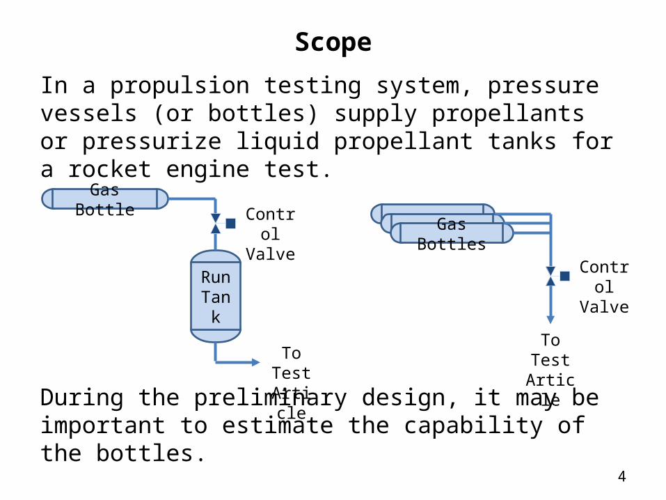
Scope
In a propulsion testing system, pressure vessels (or bottles) supply propellants or pressurize liquid propellant tanks for a rocket engine test.
During the preliminary design, it may be important to estimate the capability of the bottles.
Gas Bottles
Control Valve
To Test Article
Run Tank
Gas BottleControl Valve
To Test Article
5
Lesson Breakdown
1. Bottle Blow Down Problem Description2. Governing Thermodynamic Equations3. Example Problems4. Concluding Remarks5. Acknowledgements6. References/Credits

6
Lesson Roadmap
Problem Description
Conservation of Mass
1st Law of Thermodynamics
2nd Law of Thermodynamics
Example Problems
Isothermal Assumption
Isothermal Example
Generalized 1st Law Algorithm Example
Isentropic Assumption
Isentropic Example
Concluding Remarks
References/ Credits
Spreadsheet Excerpt Acknowledgements
7
Bottle Blow-Down Problem Description
Problem: Find the final state of a real gas in a control volume (CV) following a Uniform-Flow process.
Solution: Use the 1st and 2nd Laws of Thermodynamics for a control volume.

8
Fundamentals
9
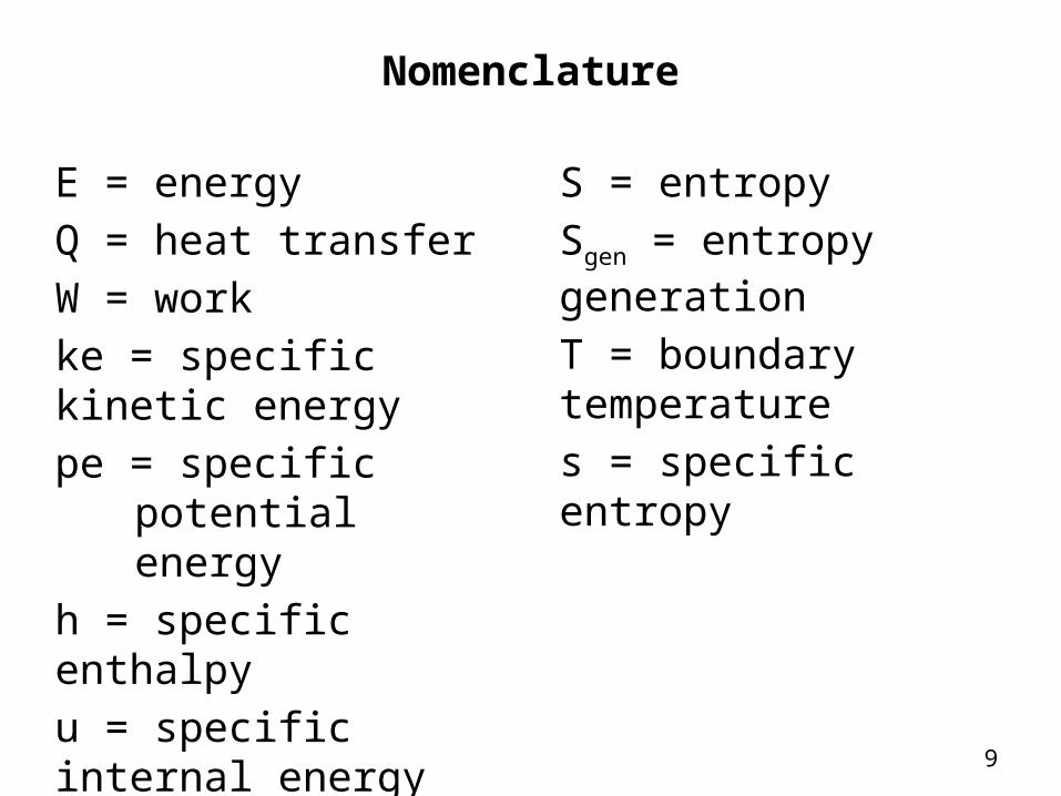
Nomenclature
E = energyQ = heat transferW = workke = specific kinetic energype = specific potential
energyh = specific enthalpyu = specific internal energym = mass
S = entropySgen = entropy generation
T = boundary temperatures = specific entropy
10
Conservation of Mass
The Conservation of Mass Principle is needed in the derivation of the 1st and 2nd Law equations and is defined by the statement below:
The net mass transfer to or from a system during a process is equal to the net change in the total mass of the system during that process (Ref. 1).
Also known as the Continuity Equation.
11
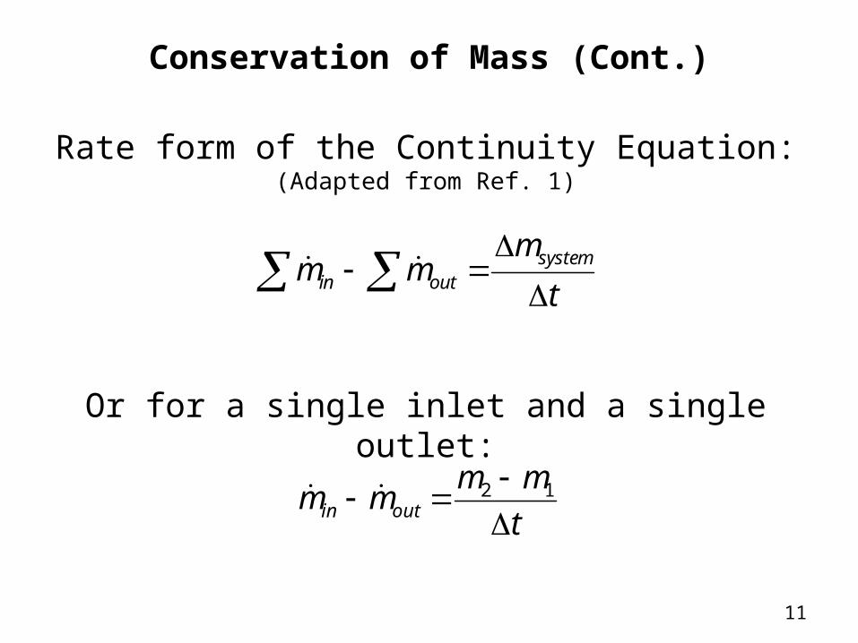
Conservation of Mass (Cont.)
Rate form of the Continuity Equation:(Adapted from Ref. 1)
t
mmm systemoutin
Or for a single inlet and a single outlet:
t
mmmm outin
12
12
1st Law of Thermodynamics
The 1st Law of Thermodynamics is defined by the following statements:
Energy cannot be created or destroyed; it can only change forms. Energy is defined as the ability to cause change. The total energy is a property of a system (Ref. 1).
The Conservation of Energy Principle is the result.
13
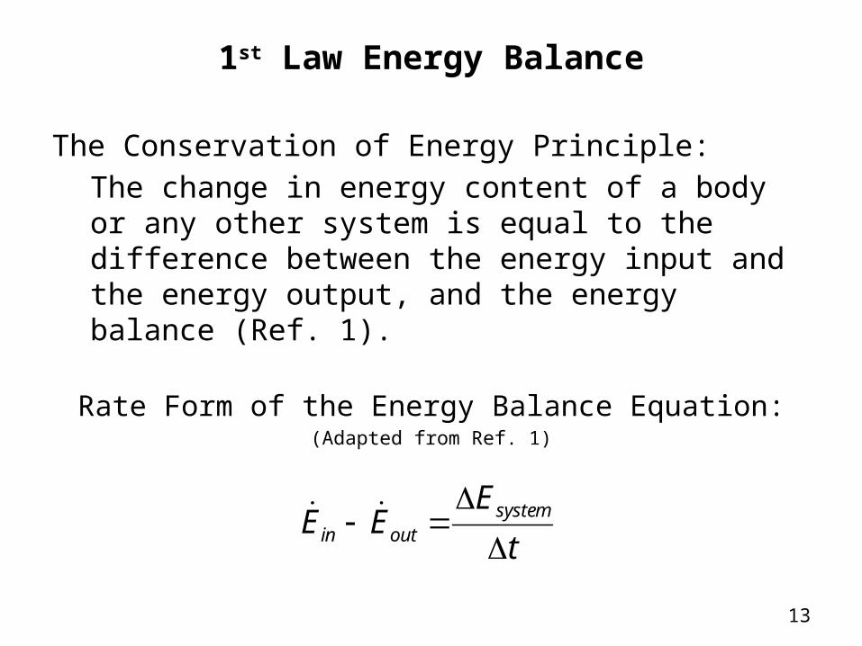
1st Law Energy Balance
The Conservation of Energy Principle:The change in energy content of a body or any other system is equal to the difference between the energy input and the energy output, and the energy balance (Ref. 1).
t
EEE systemoutin
Rate Form of the Energy Balance Equation:(Adapted from Ref. 1)
14
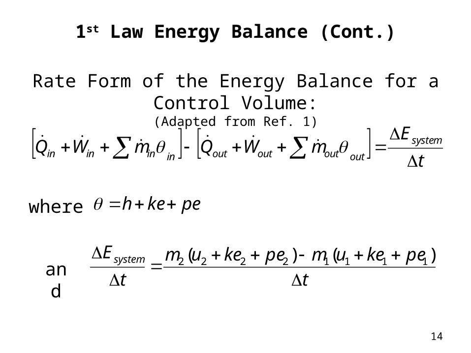
1st Law Energy Balance (Cont.)
Rate Form of the Energy Balance for a Control Volume:(Adapted from Ref. 1)
t
EmWQmWQ system
outoutoutoutinininin
t
pekeumpekeum
t
Esystem
)()( 11112222
pekeh where
and
15
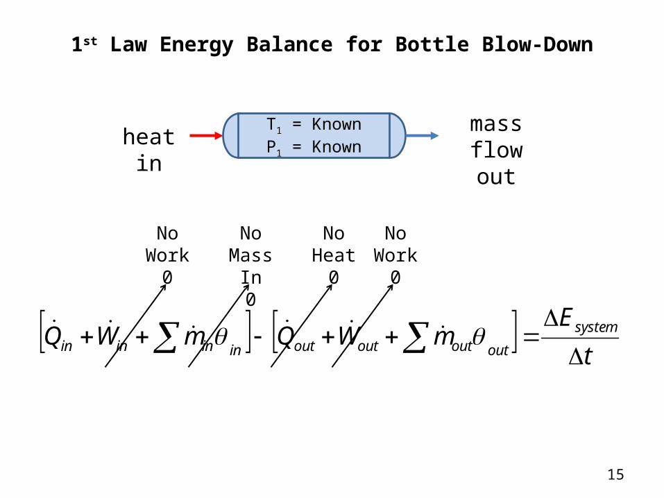
1st Law Energy Balance for Bottle Blow-Down
No Work
0
No Mass In
0
t
EmWQmWQ system
outoutoutoutinininin
NoWork
0
NoHeat
0
mass flow out
T1 = KnownP1 = Knownheat in
16
t
pekeumpekeum
t
Esystem
)()( 11112222
pekeh
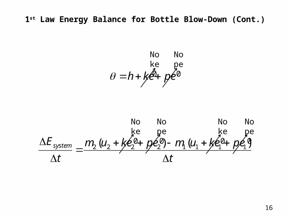
1st Law Energy Balance for Bottle Blow-Down (Cont.)
No ke0
No pe0
No ke0
No pe0
No ke0
No pe0
17
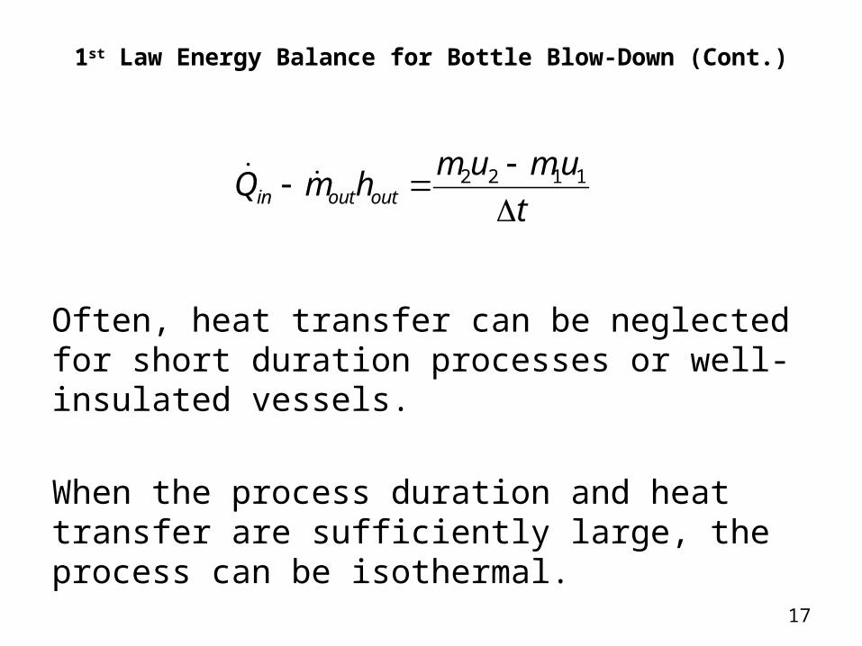
1st Law Energy Balance for Bottle Blow-Down (Cont.)
Often, heat transfer can be neglected for short duration processes or well-insulated vessels.
When the process duration and heat transfer are sufficiently large, the process can be isothermal.
t
umumhmQ outoutin
1122
18
Isothermal Blow-Down
The isothermal assumption is valid when process duration is such that gas temperatures remain approximately constant or return to the initial temperature (recovery state).
Final state fixed by density and temperature.Use thermodynamic tables or software such as
Refprop (Ref. 2) to find final state properties.
19
2nd Law of Thermodynamics
The 2nd Law of Thermodynamics is defined by the following statements:
Energy has a quality as well as a quantity. Processes have a direction and occur in the direction of decreasing quality of energy or increasing entropy (adapted from Ref. 1).
20
2nd Law of Thermodynamics (Cont.)
Entropy is a property of a system and is defined as the quantitative measure of microscopic disorder for a system generated by heat transfer, mass flow, and irreversibilities (Ref. 1).
The Entropy Balance Equation can be derived from the Clausius Inequality and the Definition of Entropy.
21
2nd Law Entropy Balance
t
SSsmsm
T
Q CVgenoutoutinin
K
k
t
SSSSS systemgenoutinheat
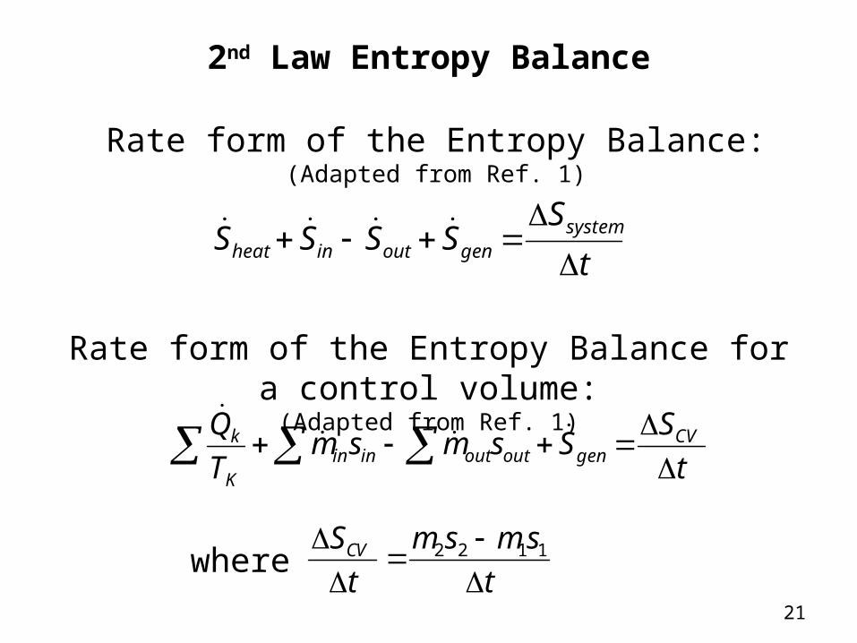
Rate form of the Entropy Balance:(Adapted from Ref. 1)
Rate form of the Entropy Balance for a control volume:(Adapted from Ref. 1)
t
smsm
t
SCV
1122where
22
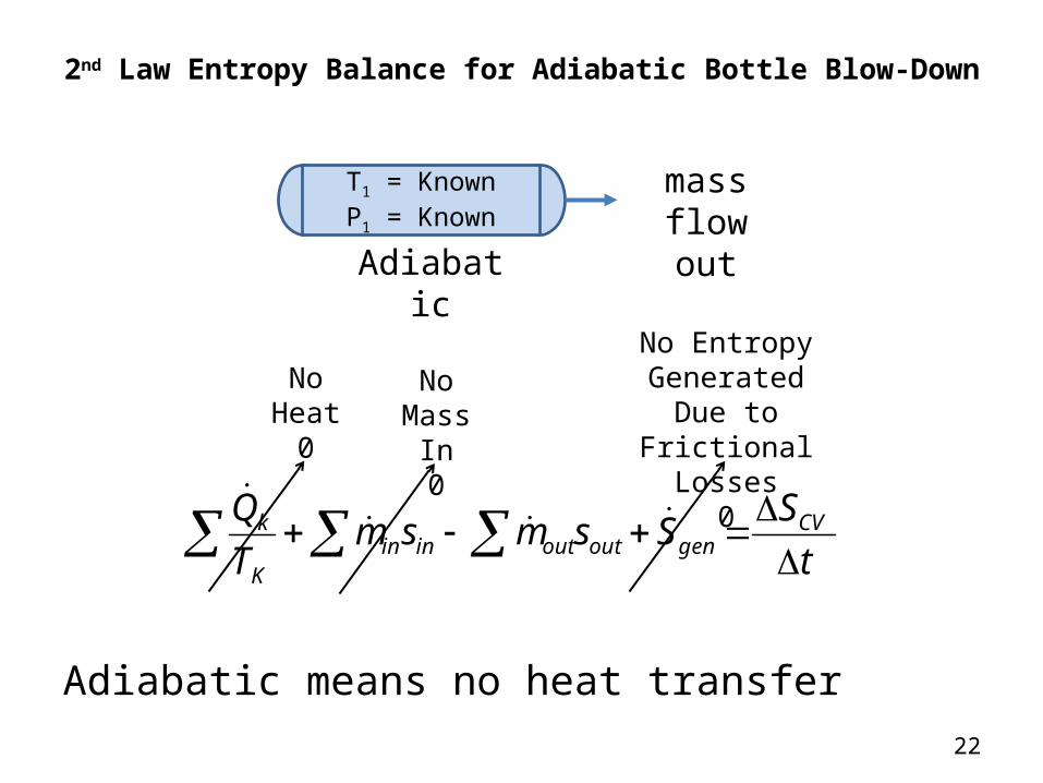
2nd Law Entropy Balance for Adiabatic Bottle Blow-Down
Adiabatic means no heat transfer
t
SSsmsm
T
Q CVgenoutoutinin
K
k
No Mass In
0
No Entropy Generated Due to Frictional Losses
0
mass flow out
T1 = KnownP1 = Known
No Heat
0
Adiabatic
23
2nd Law Entropy Balance for Adiabatic Bottle Blow-Down (Cont.)
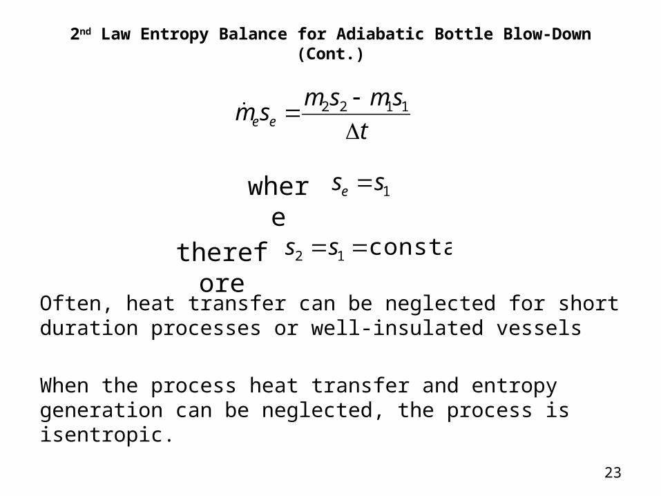
Often, heat transfer can be neglected for short duration processes or well-insulated vessels
When the process heat transfer and entropy generation can be neglected, the process is isentropic.
t
smsmsm ee
1122
1sse
constant12 ss
where
therefore
24
Isentropic Blow-Down
The isentropic assumption is valid when the process duration is short or the bottle is well-insulated.
Final state fixed by density and entropyUse thermodynamic tables or software such as
Refprop (Ref. 2) to find final state properties.

25
Examples
26
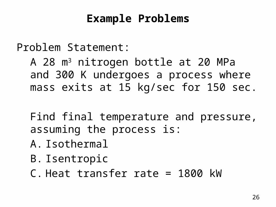
Example Problems
Problem Statement:A 28 m3 nitrogen bottle at 20 MPa and 300 K undergoes a process where mass exits at 15 kg/sec for 150 sec.
Find final temperature and pressure, assuming the process is:A. IsothermalB. IsentropicC. Heat transfer rate = 1800 kW
27
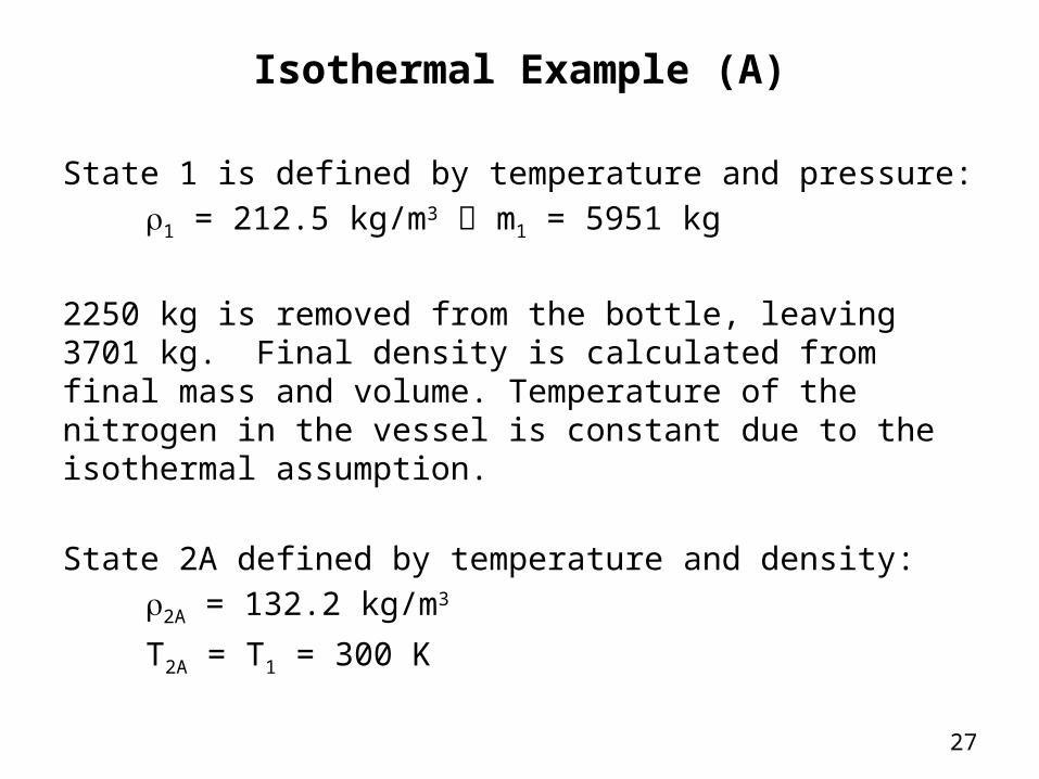
Isothermal Example (A)
State 1 is defined by temperature and pressure:r1 = 212.5 kg/m3 m1 = 5951 kg
2250 kg is removed from the bottle, leaving 3701 kg. Final density is calculated from final mass and volume. Temperature of the nitrogen in the vessel is constant due to the isothermal assumption.
State 2A defined by temperature and density:r2A = 132.2 kg/m3
T2A = T1 = 300 K
28
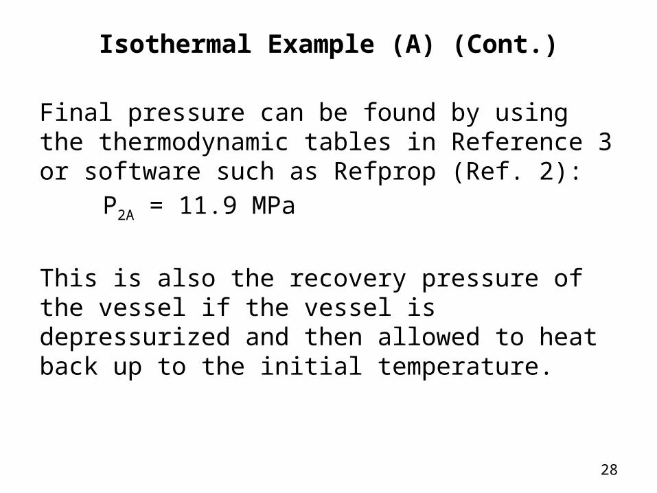
Isothermal Example (A) (Cont.)
Final pressure can be found by using the thermodynamic tables in Reference 3 or software such as Refprop (Ref. 2):
P2A = 11.9 MPa
This is also the recovery pressure of the vessel if the vessel is depressurized and then allowed to heat back up to the initial temperature.

29
Isentropic Example (B)
State 1 is defined by temperature and pressure:r1 = 212.5 kg/m3 m1 = 5951 kg
s1 = 5.163 kJ/kg*K
2250 kg is removed from the bottle, leaving 3701 kg. Final density is calculated from final mass and volume. Entropy of the nitrogen in the vessel is constant due to the isentropic assumption.
State 2B defined by density and entropy:r2B = 132.2 kg/m3
s2B = s1 = 5.163 kJ/kg*K
30
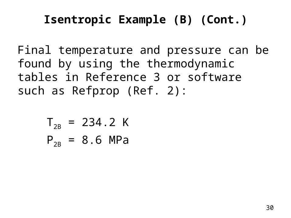
Isentropic Example (B) (Cont.)
Final temperature and pressure can be found by using the thermodynamic tables in Reference 3 or software such as Refprop (Ref. 2):
T2B = 234.2 K
P2B = 8.6 MPa
31
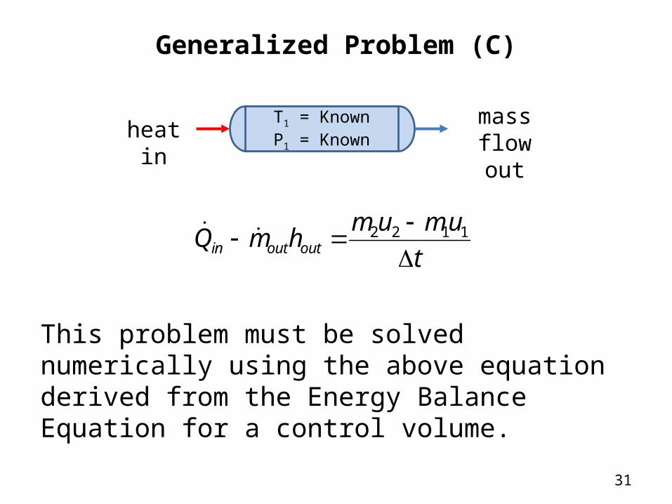
Generalized Problem (C)
This problem must be solved numerically using the above equation derived from the Energy Balance Equation for a control volume.
mass flow out
t
umumhmQ outoutin
1122
T1 = KnownP1 = Knownheat in
32
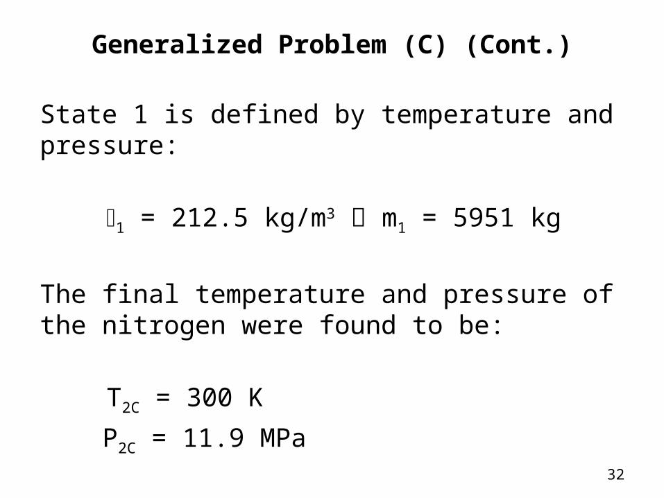
Generalized Problem (C) (Cont.)
State 1 is defined by temperature and pressure:
r1 = 212.5 kg/m3 m1 = 5951 kg
The final temperature and pressure of the nitrogen were found to be:
T2C = 300 K
P2C = 11.9 MPa
33
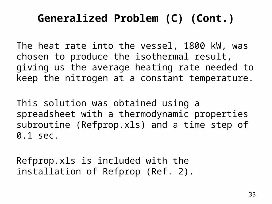
Generalized Problem (C) (Cont.)
The heat rate into the vessel, 1800 kW, was chosen to produce the isothermal result, giving us the average heating rate needed to keep the nitrogen at a constant temperature.
This solution was obtained using a spreadsheet with a thermodynamic properties subroutine (Refprop.xls) and a time step of 0.1 sec.
Refprop.xls is included with the installation of Refprop (Ref. 2).
34
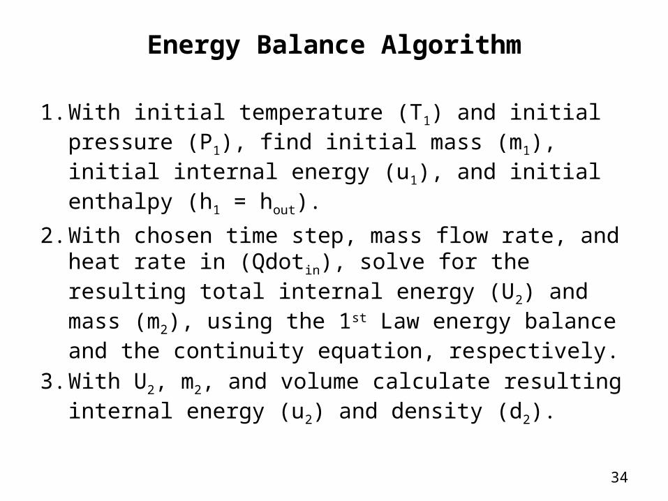
Energy Balance Algorithm
1. With initial temperature (T1) and initial pressure (P1), find initial mass (m1), initial internal energy (u1), and initial enthalpy (h1 = hout).
2. With chosen time step, mass flow rate, and heat rate in (Qdotin), solve for the resulting total internal energy (U2) and mass (m2), using the 1st Law energy balance and the continuity equation, respectively.
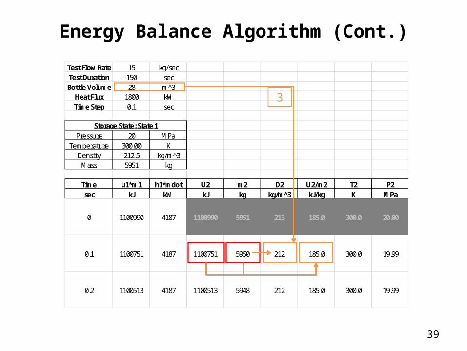
3. With U2, m2, and volume calculate resulting internal energy (u2) and density (d2).
35
Energy Balance Algorithm
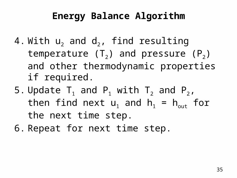
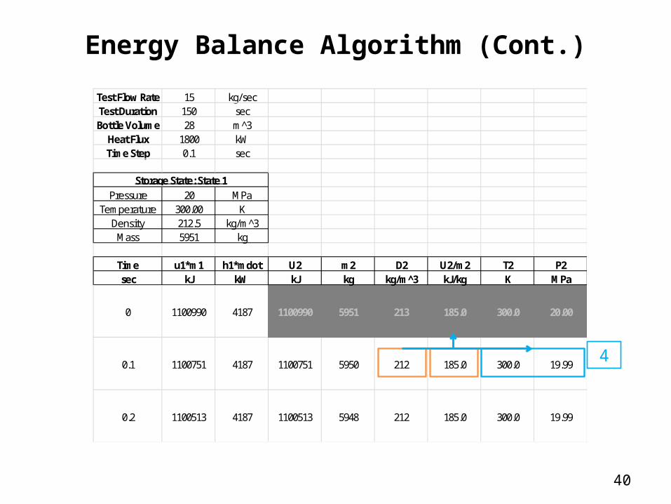
4. With u2 and d2, find resulting temperature (T2) and pressure (P2) and other thermodynamic properties if required.
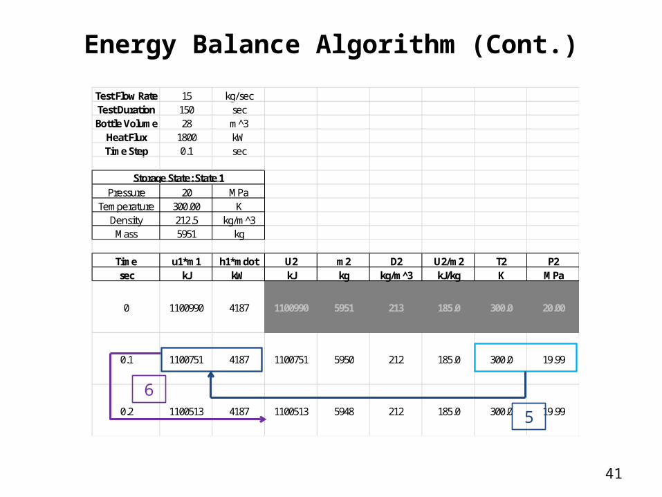
5. Update T1 and P1 with T2 and P2, then find next u1 and h1 = hout for the next time step.
6. Repeat for next time step.
36
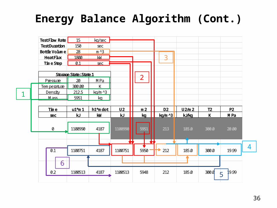
Energy Balance Algorithm (Cont.)
Test Flow Rate 15 kg/secTest Duration 150 secBottle Volume 28 m^3
Heat Flux 1800 kWTime Step 0.1 sec
Pressure 20 MPaTemperature 300.00 K
Density 212.5 kg/m^3Mass 5951 kg
Time u1*m1 h1*mdot U2 m2 D2 U2/m2 T2 P2sec kJ kW kJ kg kg/m^3 kJ/kg K MPa
0 1100990 4187 1100990 5951 213 185.0 300.0 20.00
0.1 1100751 4187 1100751 5950 212 185.0 300.0 19.99
0.2 1100513 4187 1100513 5948 212 185.0 300.0 19.99
Storage State: State 1
1
2
3
4
5
6
37
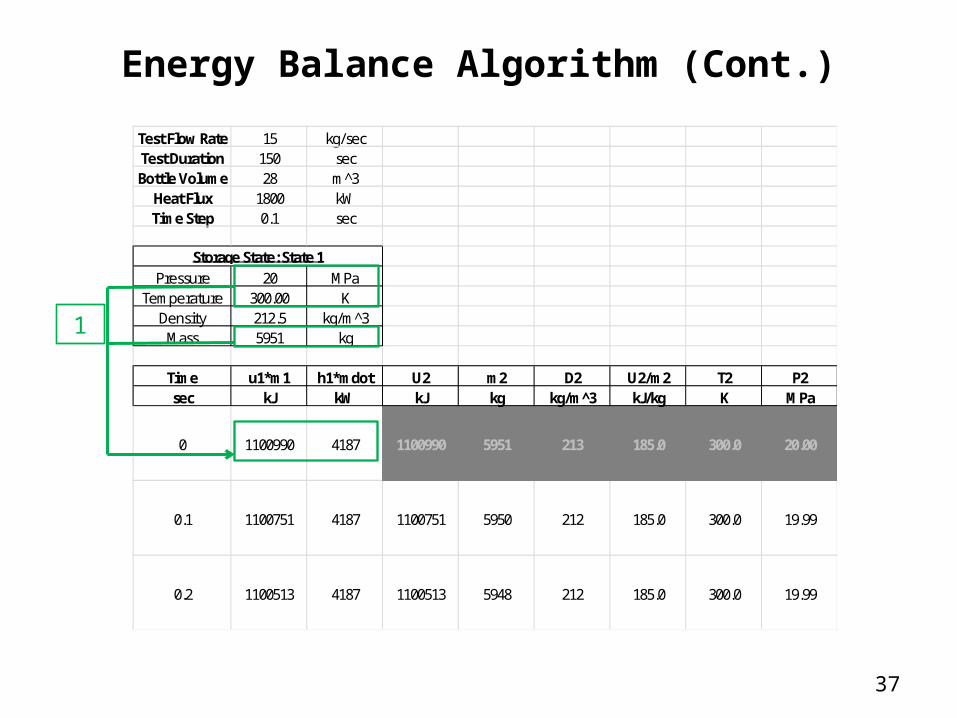
Energy Balance Algorithm (Cont.)
Test Flow Rate 15 kg/secTest Duration 150 secBottle Volume 28 m^3
Heat Flux 1800 kWTime Step 0.1 sec
Pressure 20 MPaTemperature 300.00 K
Density 212.5 kg/m^3Mass 5951 kg
Time u1*m1 h1*mdot U2 m2 D2 U2/m2 T2 P2sec kJ kW kJ kg kg/m^3 kJ/kg K MPa
0 1100990 4187 1100990 5951 213 185.0 300.0 20.00
0.1 1100751 4187 1100751 5950 212 185.0 300.0 19.99
0.2 1100513 4187 1100513 5948 212 185.0 300.0 19.99
Storage State: State 1
1
38
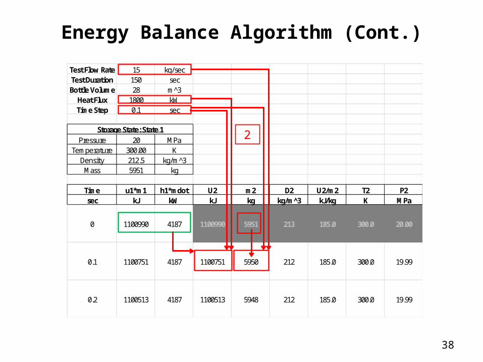
Energy Balance Algorithm (Cont.)
Test Flow Rate 15 kg/secTest Duration 150 secBottle Volume 28 m^3
Heat Flux 1800 kWTime Step 0.1 sec
Pressure 20 MPaTemperature 300.00 K
Density 212.5 kg/m^3Mass 5951 kg
Time u1*m1 h1*mdot U2 m2 D2 U2/m2 T2 P2sec kJ kW kJ kg kg/m^3 kJ/kg K MPa
0 1100990 4187 1100990 5951 213 185.0 300.0 20.00
0.1 1100751 4187 1100751 5950 212 185.0 300.0 19.99
0.2 1100513 4187 1100513 5948 212 185.0 300.0 19.99
Storage State: State 12
39
Energy Balance Algorithm (Cont.)
Test Flow Rate 15 kg/secTest Duration 150 secBottle Volume 28 m^3
Heat Flux 1800 kWTime Step 0.1 sec
Pressure 20 MPaTemperature 300.00 K
Density 212.5 kg/m^3Mass 5951 kg
Time u1*m1 h1*mdot U2 m2 D2 U2/m2 T2 P2sec kJ kW kJ kg kg/m^3 kJ/kg K MPa
0 1100990 4187 1100990 5951 213 185.0 300.0 20.00
0.1 1100751 4187 1100751 5950 212 185.0 300.0 19.99
0.2 1100513 4187 1100513 5948 212 185.0 300.0 19.99
Storage State: State 1
3
40
Energy Balance Algorithm (Cont.)
Test Flow Rate 15 kg/secTest Duration 150 secBottle Volume 28 m^3
Heat Flux 1800 kWTime Step 0.1 sec
Pressure 20 MPaTemperature 300.00 K
Density 212.5 kg/m^3Mass 5951 kg
Time u1*m1 h1*mdot U2 m2 D2 U2/m2 T2 P2sec kJ kW kJ kg kg/m^3 kJ/kg K MPa
0 1100990 4187 1100990 5951 213 185.0 300.0 20.00
0.1 1100751 4187 1100751 5950 212 185.0 300.0 19.99
0.2 1100513 4187 1100513 5948 212 185.0 300.0 19.99
Storage State: State 1
4
41
Energy Balance Algorithm (Cont.)
Test Flow Rate 15 kg/secTest Duration 150 secBottle Volume 28 m^3
Heat Flux 1800 kWTime Step 0.1 sec
Pressure 20 MPaTemperature 300.00 K
Density 212.5 kg/m^3Mass 5951 kg
Time u1*m1 h1*mdot U2 m2 D2 U2/m2 T2 P2sec kJ kW kJ kg kg/m^3 kJ/kg K MPa
0 1100990 4187 1100990 5951 213 185.0 300.0 20.00
0.1 1100751 4187 1100751 5950 212 185.0 300.0 19.99
0.2 1100513 4187 1100513 5948 212 185.0 300.0 19.99
Storage State: State 1
5
6
42
Energy Balance Algorithm (Cont.)
Notes:1. Algorithm assumes user has numerical means of
solving for thermodynamic properties2. Can be programmed in an Excel spreadsheet using
the Refprop.xls worksheet (Ref. 2)3. Recommend an initial run without heat transfer and
check against isentropic process
43
Concluding Remarks
When the Blow-Down process can be approximated as isothermal or isentropic, final state properties can be found using thermodynamic tables (or thermodynamic software).
When heat transfer is a significant factor, the energy balance equation must be solved numerically, but a simple algorithm can be used to solve for the final state.
44
Acknowledgements
Special acknowledgement is given to Steven Rickman, Ruth Amundsen, and David Gilmore for their assistance and review of this lesson.
This author is grateful to the NESC Passive Thermal Technical Discipline Team (TDT) for their contributions and technical review of this lesson.
45
References/Credits
1. “Thermodynamics: An Engineering Approach”, 4th ed., Cengel and Boles, McGraw-Hill, 2002.
2. Lemmon, E.W., Huber, M.L., McLinden, M.O. NIST Standard Reference Database 23: Reference Fluid Thermodynamic and Transport Properties-REFPROP, Version 9.0, National Institute of Standards and Technology, Standard Reference Data Program, Gaithersburg, 2010.
3. “Fundamentals of Thermodynamics”, 5th ed., Sonntag, Borgnakke and van Wylen, Wiley, 1998.
Microsoft® Clip Art was used in the presentation.


![Parameterized Modeling of Blow-Moulds for Designer …file.seekpart.com/keywordpdf/2011/1/13/2011113174443939.pdf · ing of a bottle blow-mould [2] focused on the plastic forming](https://img.pdfslide.us/doc/110x75/5b5e71d07f8b9a553d8c8f6b/parameterized-modeling-of-blow-moulds-for-designer-file-ing-of-a-bottle-blow-mould.jpg)