Embed Size (px)
Citation preview

Bosch Power-train / Exhaust Sensors Overview
Aravind KPowertrain & Exhaust Sensor Division

Bosch Sensors Overview/Training:
Internal | DGS-ES/ENG-IN_Ak | 31/08/2016
16_093
© Bosch Limited 2016. All rights reserved, also regarding any disposal, exploitation, reproduction, editing, distribution, as well as in the event of applications for industrial property rights.
2
Definition of Sensor
A sensor is a device which
measures a physical variable and
converts it into a electrical variable
which can be read by an
observer/control unit
E.g.:
‒ a mercury thermometer converts
the measured temperature into
expansion and contraction of a
liquid which can be read on a
calibrated glass tube.
‒ a thermocouple converts
temperature to an output voltage
which can be read by a voltmeter
Internal | DGS-ES/ENG-IN_Ak | 31/08/2016
16_093
© Bosch Limited 2016. All rights reserved, also regarding any disposal, exploitation, reproduction, editing, distribution, as well as in the event of applications for industrial property rights.
3
Diesel Engine Layout | CV
Bosch Sensors Overview/Training:
Internal | DGS-ES/ENG-IN_Ak | 31/08/2016
16_093
© Bosch Limited 2016. All rights reserved, also regarding any disposal, exploitation, reproduction, editing, distribution, as well as in the event of applications for industrial property rights.
4
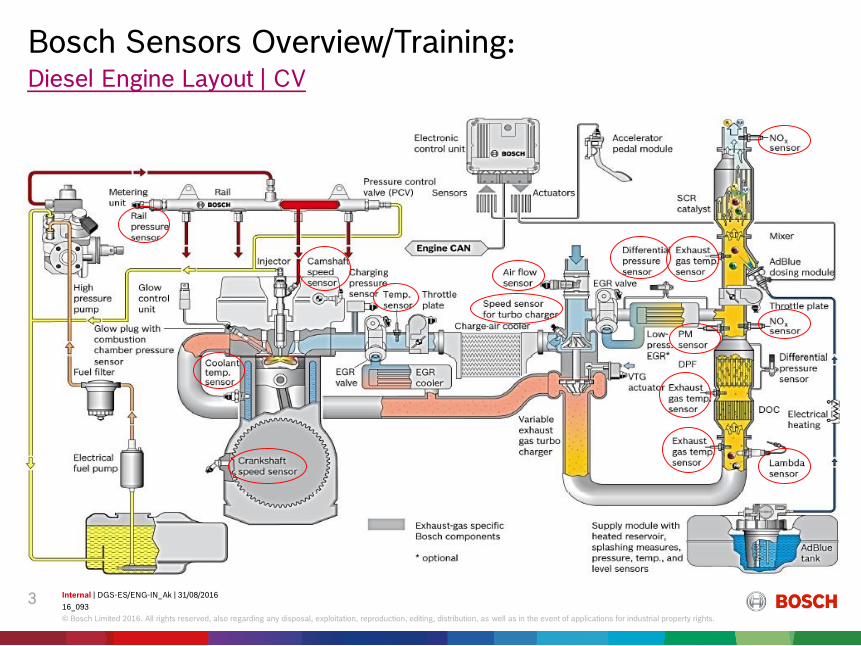
Mounting Location (spark ignited engine - PC)
Exhausttemp. sensor*
Carbon canister
Air mass meter
Camshaftphaser*
Ignition coil/spark plug
Boost pressuretemp. sensor
Acceleratorpedal modul
Temp.sensor
Fuelpumpmodule
Oxygensensor
Throttledevice(ETC)
ETC = Electronic Throttle ControlCamshaft phaser:intake and/or exhaust phasing
Ambientpressuresensor
Canisterpurge valve
Nonreturnvalves
Turbo-vacuumreservoir
Speedsensor
Injector
Turbocharger
Solenoidvalve
Phasesensor
WasteGate
WasteGate actuator
Oxygensensor
Pre catalyst
Main catalyst
Pressuresensor
Knocksensor
Fuel rail
Highpressurepump
Solenoidvalve
Dumpvalve
* optionBosch components
specifically for DI
Electronic control unit
DiagnosislampDiagnosisinterfaceImmobilizer
CAN
SCV1
1 swirl control valve (on/off or continious)
Intercooler
Bosch Sensors Overview/Training:

Internal | DGS-ES/ENG-IN_Ak | 31/08/2016
16_093
© Bosch Limited 2016. All rights reserved, also regarding any disposal, exploitation, reproduction, editing, distribution, as well as in the event of applications for industrial property rights.
5
Rotational Speed Sensor Crank
(RSC, DG)
High Pressure Sensors
(RPS, HPS)
Camshaft Position Sensor
(CPS, PG)
Oxygen Sensor
(LS)
Particulate Matter
Sensor
(EGS-PM)
Mass Air Flow Sensor
(HFM)
NOx Sensor
(EGS-NX)
Knock Sensor
(KS)
Low Pressure Sensors
(LPS)
Temperature Sensor
(TS)
Pressure Based Air
Flow Meter
(PFM)
Speed Sensor Turbo Charger
(RS-T1)
Bosch exhaust and powertrain sensor portfolioSensor portfolio overview
Exhaust & powertrain sensors
Throttle Position
Sensor
(TPS)
Exh Temp Sensor
(EGS-T)

Internal | DGS-ES/ENG-IN_Ak | 31/08/2016
16_093
© Bosch Limited 2016. All rights reserved, also regarding any disposal, exploitation, reproduction, editing, distribution, as well as in the event of applications for industrial property rights.
6
Powertrain sensor portfolio DGS-ESProduct Area | Powertrain Sensors
Pressure
sensors
(xPS)
Air mass
sensors
(xFM)
Speed &
position
sensors
(RSx, CPS,
TPS)
Knock
sensors
(KS)
Temperature
sensors
(TS)

Internal | DGS-ES/ENG-IN_Ak | 31/08/2016
16_093
© Bosch Limited 2016. All rights reserved, also regarding any disposal, exploitation, reproduction, editing, distribution, as well as in the event of applications for industrial property rights.
7
Features
Application
Low Pressure Sensor - LPS
Silicon micromechanics, 1-chip-concept
Standardized design for different applications
Absolute, differential, relative pressure applications
Pressure range 0 …… 400 kPa Max-absolute
Operating temperature range -40 …. 130°C(optional 150°C)
Working Principle : Wheatstone Bridge(Pressure transducers)
Measures Intake Manifold Air Pressure & Temperature
Measures Boost pressure.
DSS3
DSS3-TF
Facts and Figures
SOP : 2006
SOP(India) : 2010
Mounting Location
Intake manifold
After turbo-charger
Internal | DGS-ES/ENG-IN_Ak | 31/08/2016
16_093
© Bosch Limited 2016. All rights reserved, also regarding any disposal, exploitation, reproduction, editing, distribution, as well as in the event of applications for industrial property rights.
8
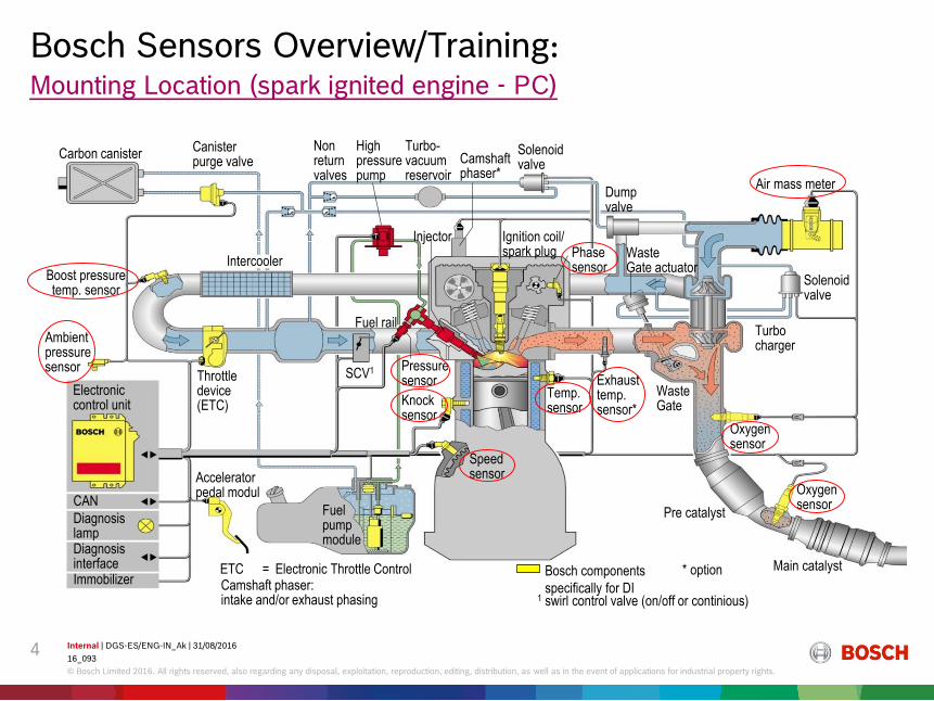
Functional Principle
0
5
0 115
Absolutdruck pabs in kPa
Au
sg
an
gssp
an
un
g U
A in
V
0,4
10
4,65
Use : To measure Intake mainfold pressure & Temp.
UA = output voltage in V
US = supply voltage in V
pabs = absolute pressure in kPa
c0 = -0,1/105
c1 = 0,85/105 kPa-1
UA= (c1pabs+c0)US
Transfer function and accuracy
(e.g. 10 - 115 kPa)
0
0,5
1
1,5
2
2,5
3
3,5
4
-50 150
Temperatur t in °C
Fakto
r
10-40 85 130

Internal | DGS-ES/ENG-IN_Ak | 31/08/2016
16_093
© Bosch Limited 2016. All rights reserved, also regarding any disposal, exploitation, reproduction, editing, distribution, as well as in the event of applications for industrial property rights.
9
Differential Pressure Sensor DS-D2Features
Application
Pressure ranges from 0 to 125 kPa
Silicon MEMS Sensor chip (pressure transducer with integrated electronic circuit) on hybrid ceramic
1-Chip concept with mechanical differential pressure measurement
Sensing element protected by media resistant gel
Media robust design for DPF application
Operating temperature range -40 …. 130°C(optional 150°C)
Working Principle : Wheatstone Bridge(Pressure transducers)
Measures pressure & temperature across EGR unit & DPF.Facts and Figures
SOP : 2006
EGR – Exhaust Gas Re-circulation
DPF – Diesel Particulate Filter
Mounting Location
Across DPF
After EGR

Internal | DGS-ES/ENG-IN_Ak | 31/08/2016
16_093
© Bosch Limited 2016. All rights reserved, also regarding any disposal, exploitation, reproduction, editing, distribution, as well as in the event of applications for industrial property rights.
10
Features
Stainless steel sensing element with metal thin film strain gages
Digital circuit concept with analogue output signal
Modular, compact design, small overall height
Pressure ranges: 150, 180, 200, 220, 240, 270 Mpa
Temperature range -40°C/+130°C(optional 150°C)
Working Principle : Wheatstone Bridge(Pressure transducers)
Measures the pressure of fuel in the rail – Diesel Application.
Measures the pressure of fuel in GDI application.
Application
Facts and Figures
SOP : 2001
High Pressure Sensor
Mounting Location
On the fuel rail

Internal | DGS-ES/ENG-IN_Ak | 31/08/2016
16_093
© Bosch Limited 2016. All rights reserved, also regarding any disposal, exploitation, reproduction, editing, distribution, as well as in the event of applications for industrial property rights.
11
Functional Principle
Sensorelement
Pressure14 MPa0
0,2
0,5
4,5
V
Ou
tpu
t V
olta
ge
4,8

Internal | DGS-ES/ENG-IN_Ak | 31/08/2016
16_093
© Bosch Limited 2016. All rights reserved, also regarding any disposal, exploitation, reproduction, editing, distribution, as well as in the event of applications for industrial property rights.
12
Hot Film Air Mass sensor (HFM8)
Features
Reduced air mass tolerances and improved pulsation behavior New part tolerance: 1.5%*
Lifetime tolerance: 3.5%*
Pulsation error : 6%*
Flexible modular system: Optional integration of additional pressure-, temperature- and humidity-
sensor / SENT or FAS interface / 5V or 12V supply voltage / Optional
applicable digital signal filters, Optional Chipheating function
Reduced power consumption < 20mA (for standard sensor)
Working Principle : Wheatstone Bridge(Thermistors)
Measures the mass(kg/hr) & temperature of Intake air.
Humidity & pressure measurement options available.
Application65
34
9
Measures in mm
Facts and Figures
SOP : 2014 Mounting Location
After Air Filter in the AISAIS – Air Intake System
Internal | DGS-ES/ENG-IN_Ak | 31/08/2016
16_093
© Bosch Limited 2016. All rights reserved, also regarding any disposal, exploitation, reproduction, editing, distribution, as well as in the event of applications for industrial property rights.
13
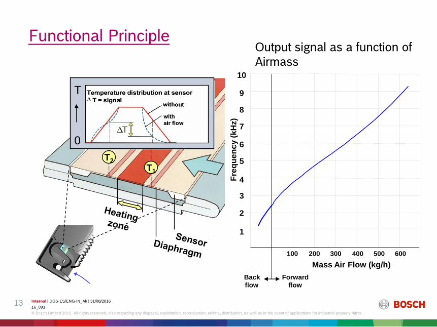
Functional Principle
T2
T1
0
T
1
2
4
5
6
7
8
9
10
Forwardflow
Back
300 400 500
3
Fre
qu
en
cy (
kH
z)
flow
100 200 600
Mass Air Flow (kg/h)
Output signal as a function of
Airmass

Internal | DGS-ES/ENG-IN_Ak | 31/08/2016
16_093
© Bosch Limited 2016. All rights reserved, also regarding any disposal, exploitation, reproduction, editing, distribution, as well as in the event of applications for industrial property rights.
14
Pressure Based Air Flow Meter - PFM
Features
Air flow measurement using dynamic pressure
Engine near, compact mounting position after charge air cooler
Measurement of dynamic pressure (Pd), reference pressure (PS) and temperature (T)
Calculation of the air mass on basis of Bernoulli-equation
Suitable for off-highway application
Working Principle : Bernoulli equation + Ideal Gas equation +
Conservation of mass
Application
Facts and Figures
SOP(pilot): 12/2017
Preliminary Design – Functional Sample (PFM)
Measures the mass(kg/hr) & temperature of Intake air.
Mounting Location
After Air Filter in the AIS
AIS – Air Intake System

Ptot
T
Ps
Internal | DGS-ES/ENG-IN_Ak | 31/08/2016
16_093
© Bosch Limited 2016. All rights reserved, also regarding any disposal, exploitation, reproduction, editing, distribution, as well as in the event of applications for industrial property rights.
15
Functional principle
Robust measurement of air mass flow
Measurement of dynamic- (Pd) and reference pressure (Ps) by two pressure sensors
(Δp and Ps); measurement of temperature (T)
Fig. acc. To Prandtl tube principle
(Ps)
Temperature
(T)
Air
Air mass calculation:
Integrated Sensors :

Internal | DGS-ES/ENG-IN_Ak | 31/08/2016
16_093
© Bosch Limited 2016. All rights reserved, also regarding any disposal, exploitation, reproduction, editing, distribution, as well as in the event of applications for industrial property rights.
16
Knock Sensor – KS-4
Features
Broadband type, 5 to 22 kHz
Linear characteristics over large frequency range
30mV/g at 5 kHz, active output
Standard version: -40 ... 130°C
Extended heat version: -40 ... 150°C
Technology: piezo-ceramic ring
Engine protection from uncontrolled combustion
Working Principle : Piezo-electric.
Senses the engine-knocking/vibrations
Application
KS-4S
KS-4K
Facts and Figures
SOP : 2002 Mounting Location
On Engine block near cylinders

Internal | DGS-ES/ENG-IN_Ak | 31/08/2016
16_093
© Bosch Limited 2016. All rights reserved, also regarding any disposal, exploitation, reproduction, editing, distribution, as well as in the event of applications for industrial property rights.
17
Functional Principle
Characteristic curve U = f ( f )
mV/g
50
40
30
20
10
0 5 10 15 20 kHza Q/C = U excitation by acceleration
piezo effect

Internal | DGS-ES/ENG-IN_Ak | 31/08/2016
16_093
© Bosch Limited 2016. All rights reserved, also regarding any disposal, exploitation, reproduction, editing, distribution, as well as in the event of applications for industrial property rights.
18
Water/Oil Temperature Sensor
Features
Temperature range: -40°C ↔ +130°C (optional 150°C)
Supply voltage: 5V (only with series resistance)
Response time ((63): 20 …80°C): 10 …15 sec
Vibration proof: max. a(sin) = 300 m/s²
Isolation: 500V for 1 …3sec.
Durable against operating materials (fuel, oil, battery acid, ...)
Durable against water according DIN 40 050, IPX4K 9K
Working Principle : NTC – Negative temperature coefficient
Measures Engine coolant water / oil temperature
Application
Facts and Figures
SOP(India): 2011 Mounting Location
On Engine block for air cooled engines
Internal | DGS-ES/ENG-IN_Ak | 31/08/2016
16_093
© Bosch Limited 2016. All rights reserved, also regarding any disposal, exploitation, reproduction, editing, distribution, as well as in the event of applications for industrial property rights.
19
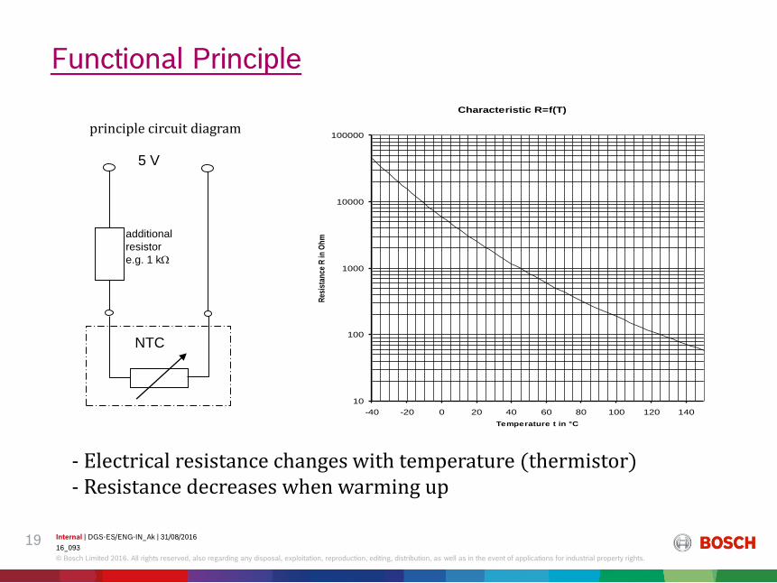
Functional Principle
5 V
additional
resistor
e.g. 1 k
NTC
principle circuit diagram
Characteristic R=f(T)
10
100
1000
10000
100000
-40 -20 0 20 40 60 80 100 120 140
Temperature t in °C
Res
ista
nce
R in
Oh
m
- Electrical resistance changes with temperature (thermistor)- Resistance decreases when warming up

Internal | DGS-ES/ENG-IN_Ak | 31/08/2016
16_093
© Bosch Limited 2016. All rights reserved, also regarding any disposal, exploitation, reproduction, editing, distribution, as well as in the event of applications for industrial property rights.
20
Crankshaft Sensor DG-6
Features
Measures speed of the crank wheel/engine.
Application
2-wire Variable Reluctance principle
Speed range from 20 … 7000 rpm
Wide temperature range -40 ... 130°C(optional 150°C)
Working air gap range – 0.3 to 1.8 mm
Available as plug-in or cable type.
Typical application: Crankshaft sensor with 60-2 teeth target
Working Principle : Faraday’s law of electro-magnetic induction
Facts and Figures
SOP : 1993
SOP(India): 2010
Mounting Location
On Crank Wheel/fly wheel
Crank pulley

Internal | DGS-ES/ENG-IN_Ak | 31/08/2016
16_093
© Bosch Limited 2016. All rights reserved, also regarding any disposal, exploitation, reproduction, editing, distribution, as well as in the event of applications for industrial property rights.
21
Functional Principle
Function principle Signal generation
Output versus speed Signal with a 60-2 target
Internal | DGS-ES/ENG-IN_Ak | 31/08/2016
16_093
© Bosch Limited 2016. All rights reserved, also regarding any disposal, exploitation, reproduction, editing, distribution, as well as in the event of applications for industrial property rights.
22
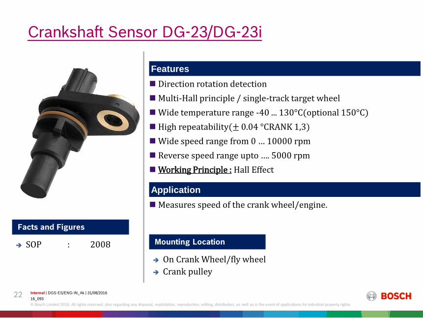
Crankshaft Sensor DG-23/DG-23i
Features
Measures speed of the crank wheel/engine.
Application
Direction rotation detection
Multi-Hall principle / single-track target wheel
Wide temperature range -40 ... 130°C(optional 150°C)
High repeatability(± 0.04 °CRANK 1,3)
Wide speed range from 0 … 10000 rpm
Reverse speed range upto …. 5000 rpm
Working Principle : Hall Effect
Facts and Figures
SOP : 2008 Mounting Location
On Crank Wheel/fly wheel
Crank pulley

Internal | DGS-ES/ENG-IN_Ak | 31/08/2016
16_093
© Bosch Limited 2016. All rights reserved, also regarding any disposal, exploitation, reproduction, editing, distribution, as well as in the event of applications for industrial property rights.
23
Functional Principle

Internal | DGS-ES/ENG-IN_Ak | 31/08/2016
16_093
© Bosch Limited 2016. All rights reserved, also regarding any disposal, exploitation, reproduction, editing, distribution, as well as in the event of applications for industrial property rights.
24
Speed Sensor for Turbo Charger - RS-T1
Features
Measures the speed of the turbo-charger
Application
Detection of each compressor blade up to 400 000 rpm T/C speed
Integrated high temperature electronics for best EMC behavior
Temperature range up to 200 °C (sensor head)
Frequency signal comparable to a speed sensor
No additional ASIC in ECU required
Working Principle : Faraday’s law of electro-magnetic induction
Facts and Figures
SOP : 01/2016 Mounting Location
On the turbo-charger

Internal | DGS-ES/ENG-IN_Ak | 31/08/2016
16_093
© Bosch Limited 2016. All rights reserved, also regarding any disposal, exploitation, reproduction, editing, distribution, as well as in the event of applications for industrial property rights.
25
Magnet
Coil
Functional Principle
Air gap range up to 2 mm (blind hole)
Ambient temperature
at the sensor tip:
-40 °C ... +180 °C
(short term +200 °C)
Rotation speed
/ Signal band width
ca. 10 … 400·103 rpm
/ 2 kHz ... 70 kHz
Measurement principle Inductive passive
Sensing coil
Target wheel profile
Magnet

Internal | DGS-ES/ENG-IN_Ak | 31/08/2016
16_093
© Bosch Limited 2016. All rights reserved, also regarding any disposal, exploitation, reproduction, editing, distribution, as well as in the event of applications for industrial property rights.
26
Cam Position sensor PG-3.8 /-3.9 / CPS4
Features
Single Hall principle / single-track target wheel
True-Power-On
Twist insensitive mounting
Wide temperature range -40 ... 130°C(optional 150°C)
Small sensor diameter 11.3 mm (PG-3.9)
Working Principle : Hall effect
Determines the position of the camshaft
Application
Facts and Figures
SOP : 2003
PG3.9
PG3.8
CPS4Mounting Location
Rear-end of the cam shaft

Internal | DGS-ES/ENG-IN_Ak | 31/08/2016
16_093
© Bosch Limited 2016. All rights reserved, also regarding any disposal, exploitation, reproduction, editing, distribution, as well as in the event of applications for industrial property rights.
27
Functional principle
Basics of Application.
target wheel
Magnetic induction B depending on wheel angle
angle of target wheel
electricaloutput-signal
0 45 90 135 180 225 270 315 360
slot
switching
threshold
toothB

Internal | DGS-ES/ENG-IN_Ak | 31/08/2016
16_093
© Bosch Limited 2016. All rights reserved, also regarding any disposal, exploitation, reproduction, editing, distribution, as well as in the event of applications for industrial property rights.
28
Throttle Position Sensor
Features
Angle sensor with linear functional characteristic (Potentiometer)
Throttle valve angle 0..86°
Minimum flange bore-to-bore distance 40 mm
Throttle shaft interface 8 mm with D-shaped cross-section
Supply voltage 5V
Temperature range -40°..+130°C
Working Principle : Potentiometer
Determines the position of the throttle valve
Application
Facts and Figures
SOP(India) : 2016 Mounting Location
On the throttle body
Internal | DGS-ES/ENG-IN_Ak | 31/08/2016
16_093
© Bosch Limited 2016. All rights reserved, also regarding any disposal, exploitation, reproduction, editing, distribution, as well as in the event of applications for industrial property rights.
29
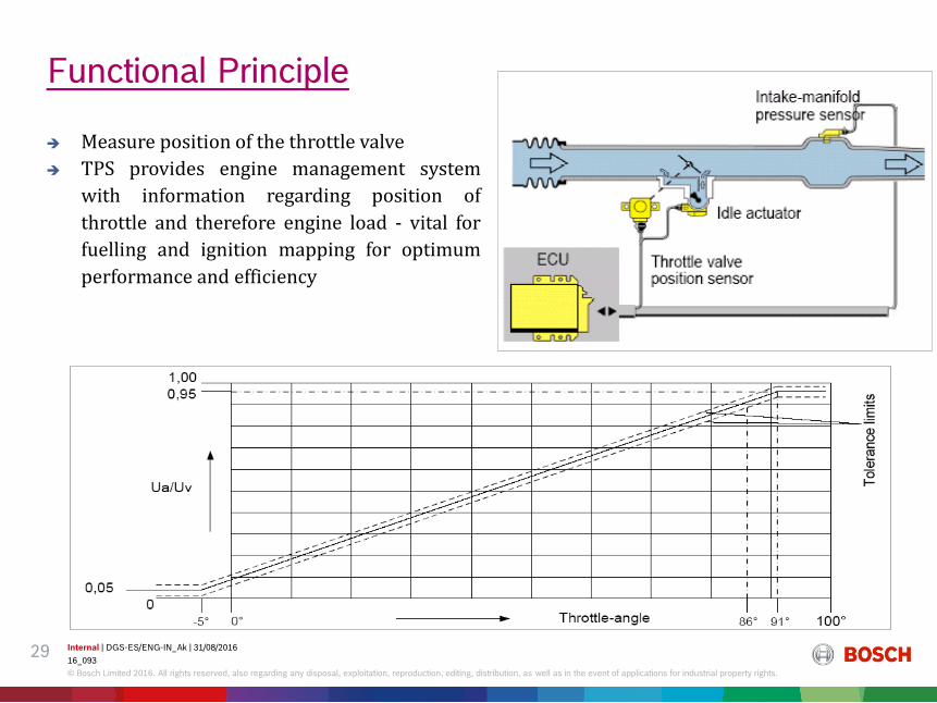
Functional Principle
Measure position of the throttle valve
TPS provides engine management system
with information regarding position of
throttle and therefore engine load - vital for
fuelling and ignition mapping for optimum
performance and efficiency
Internal | DGS-ES/ENG-IN_Ak | 31/08/2016
16_093
© Bosch Limited 2016. All rights reserved, also regarding any disposal, exploitation, reproduction, editing, distribution, as well as in the event of applications for industrial property rights.
30
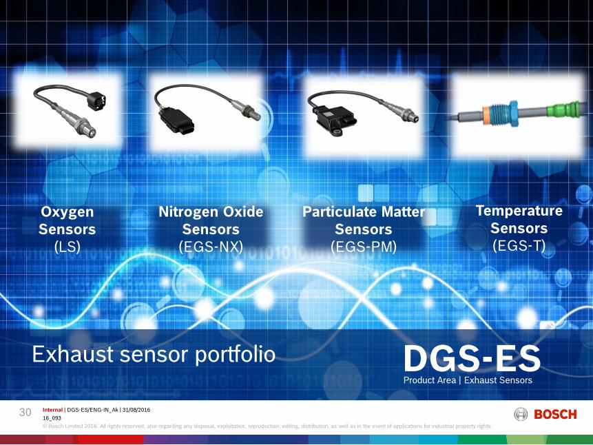
Exhaust sensor portfolio DGS-ESProduct Area | Exhaust Sensors
Nitrogen Oxide
Sensors
(EGS-NX)
Particulate Matter
Sensors
(EGS-PM)
Temperature
Sensors
(EGS-T)
Oxygen
Sensors
(LS)
Internal | DGS-ES/ENG-IN_Ak | 31/08/2016
16_093
© Bosch Limited 2016. All rights reserved, also regarding any disposal, exploitation, reproduction, editing, distribution, as well as in the event of applications for industrial property rights.
31
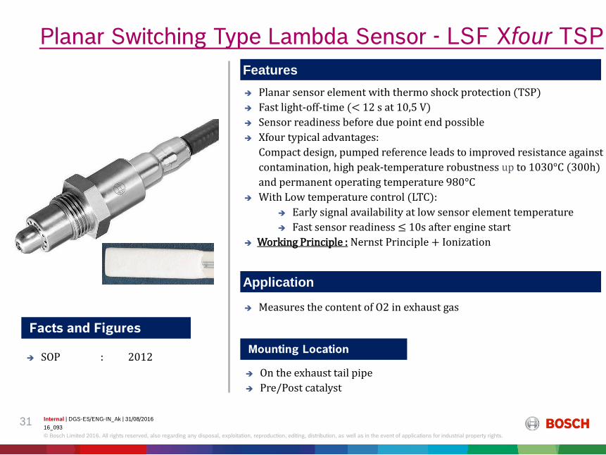
Planar sensor element with thermo shock protection (TSP)
Fast light-off-time (< 12 s at 10,5 V)
Sensor readiness before due point end possible
Xfour typical advantages:
Compact design, pumped reference leads to improved resistance against
contamination, high peak-temperature robustness up to 1030°C (300h)
and permanent operating temperature 980°C
With Low temperature control (LTC):
Early signal availability at low sensor element temperature
Fast sensor readiness ≤ 10s after engine start
Working Principle : Nernst Principle + Ionization
Planar Switching Type Lambda Sensor - LSF Xfour TSP
Features
Application
Facts and Figures
SOP : 2012Mounting Location
On the exhaust tail pipe
Pre/Post catalyst
Measures the content of O2 in exhaust gas

Internal | DGS-ES/ENG-IN_Ak | 31/08/2016
16_093
© Bosch Limited 2016. All rights reserved, also regarding any disposal, exploitation, reproduction, editing, distribution, as well as in the event of applications for industrial property rights.
32
Sensing cell
HeaterReferenceair PO2
PO2
ZrO2-Ceramic
Electrodes
Porous protective layer
Insulation
PO2US
RT
4F= In
PO2
Sensor Characteristic Curve
Normalized A/F ratio
Se
nso
r vo
lta
ge
0 0.98 1.0 1.02
Ureg
0
0.3
0.6
0.9
V
Exhaust gas
Functional Principle

Internal | DGS-ES/ENG-IN_Ak | 31/08/2016
16_093
© Bosch Limited 2016. All rights reserved, also regarding any disposal, exploitation, reproduction, editing, distribution, as well as in the event of applications for industrial property rights.
33
Facts and Figures
SOP : 2003
Measures the content of O2 in exhaust gas
Fast sensor readiness after engine start due to Thermo-shock protection
(TSP) & Fast light-off (FLO ≤ 12s)
Lambda control for gasoline engines
Continuous signal & wide measurement range (0,70 – air)
Planar sensor element with integrated, central heater
Robust sensor element design through pumped reference
High peak-temperature robustness up to 1030°C (250h);
permanent operating temperature 930°C
Trim resistor in connector housing
Working Principle : Nernst Principle + Ionization
Planar Wideband Lambda Sensor – LSU 4.9
Features
Application
Mounting Location
On the exhaust tail pipe
Pre/Post catalyst
Internal | DGS-ES/ENG-IN_Ak | 31/08/2016
16_093
© Bosch Limited 2016. All rights reserved, also regarding any disposal, exploitation, reproduction, editing, distribution, as well as in the event of applications for industrial property rights.
34
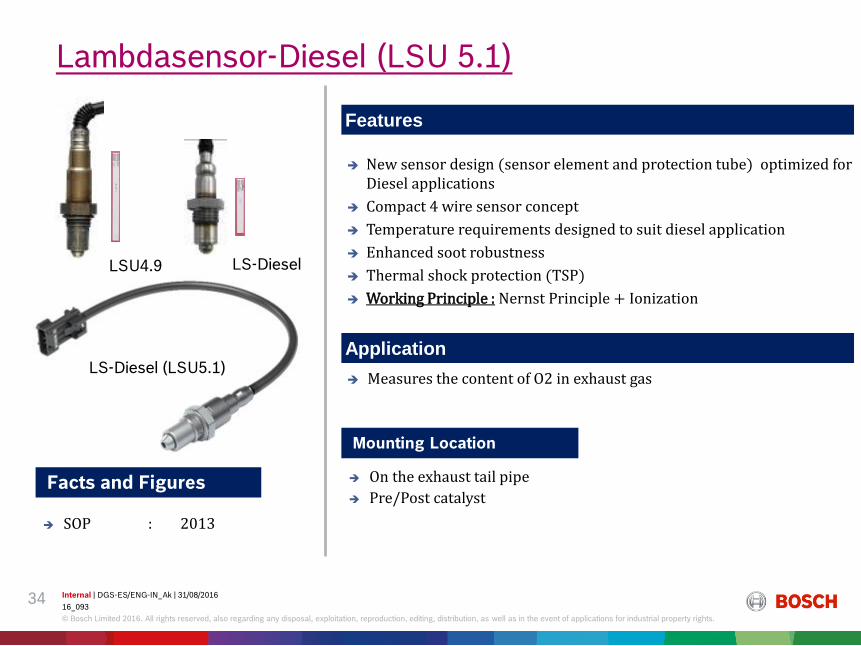
Facts and Figures
SOP : 2013
Measures the content of O2 in exhaust gas
New sensor design (sensor element and protection tube) optimized for Diesel applications
Compact 4 wire sensor concept
Temperature requirements designed to suit diesel application
Enhanced soot robustness
Thermal shock protection (TSP)
Working Principle : Nernst Principle + Ionization
Lambdasensor-Diesel (LSU 5.1)
Features
Application
LSU4.9 LS-Diesel
LS-Diesel (LSU5.1)
Mounting Location
On the exhaust tail pipe
Pre/Post catalyst

Internal | DGS-ES/ENG-IN_Ak | 31/08/2016
16_093
© Bosch Limited 2016. All rights reserved, also regarding any disposal, exploitation, reproduction, editing, distribution, as well as in the event of applications for industrial property rights.
35
Functional Principle
Outer pump
electrode
Inner
pump-
electrode
Reference air electrodeHeater
Exhaust:
O2, CO,
H2, HC
Diffusion-
barrier
O2-
O2
2P O~ pI
Zircondioxide
IP-MeasureApply Voltage e-040812
measure chamber
state: target 450 mV

Internal | DGS-ES/ENG-IN_Ak | 31/08/2016
16_093
© Bosch Limited 2016. All rights reserved, also regarding any disposal, exploitation, reproduction, editing, distribution, as well as in the event of applications for industrial property rights.
36
Facts and Figures
SOP(PC) : 02/2015
SOP(CV) : [12 V] – 07/2016
[24 V] – 01/2017
EGS-NX 2nd Gen (Nitrogen Oxides)
Features
Application
SCU Digital output, CAN bus capable, enables for ...
Standardized protocol (e.g. SAE J1939) or customer-specific CAN
NOx and O2 signal
NH3 as an additional contribution to the NOx signal
125°C environmental temperature SCU, engine mounting of SCU possible
Specified for 6.000* h / 186.500 miles (300.000 km)
Additional pin for position detection / Sensor classified in QM system(ASIL)
Working Principle : Nernst Principle + Ionization
Measures the content of NOx & O2 in exhaust gas
Mounting Location
On the exhaust tail pipe
Post catalyst

Internal | DGS-ES/ENG-IN_Ak | 31/08/2016
16_093
© Bosch Limited 2016. All rights reserved, also regarding any disposal, exploitation, reproduction, editing, distribution, as well as in the event of applications for industrial property rights.
37
Functional Principle

Internal | DGS-ES/ENG-IN_Ak | 31/08/2016
16_093
© Bosch Limited 2016. All rights reserved, also regarding any disposal, exploitation, reproduction, editing, distribution, as well as in the event of applications for industrial property rights.
38
Facts and Figures
SOP : 2014
EGS-PM sensor
Features
Application
OBD: DPF monitoring for US MY2013 and EU6 by direct measurement of particulate matter downstream DPF.
Sensor equipped with active electronics in separate SCU
Sensing principle: resistivity measurement of deposited soot;
sensor regeneration by periodic heating.
Ceramic sensing element with integrated heater, temperature
sensing element and inter-digital electrodes.
Communication with ECU: sensor with CAN interface.
Electrical interface: 12V supply(PC), 24V(CV).
Working Principle : Resistance measurement
Measures the amount of particulate matter from the exhaust
Mounting Location
On the exhaust tail pipe
Post catalyst

Internal | DGS-ES/ENG-IN_Ak | 31/08/2016
16_093
© Bosch Limited 2016. All rights reserved, also regarding any disposal, exploitation, reproduction, editing, distribution, as well as in the event of applications for industrial property rights.
39
Functional Principle
(1) positioning of sensor in exhaust pipe
(3) protection tube guides partial gas stream over interdigital electrodes (IDE)
(5) Growth of conductive soot paths through continuous accumulation
(4) soot accumulation on and between interdigital electrodes (IDE)
(2) protection tube bleeds off partial gas stream from main stream in pipe
Sensorsubstrat
exhaust gas
electrode
electrode
Resistance between interdigital electrodes depends on soot adsorption
Periodic heating regenerates sensor surface by burning soot layer off
Internal | DGS-ES/ENG-IN_Ak | 31/08/2016
16_093
© Bosch Limited 2016. All rights reserved, also regarding any disposal, exploitation, reproduction, editing, distribution, as well as in the event of applications for industrial property rights.
40
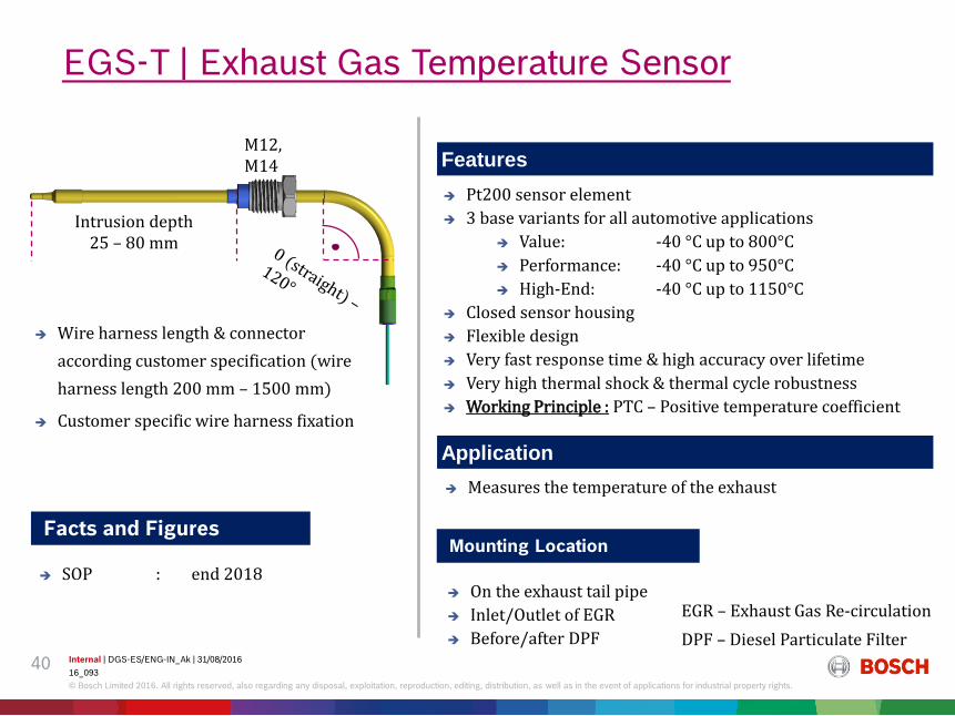
Facts and Figures
SOP : end 2018
Pt200 sensor element
3 base variants for all automotive applications
Value: -40 °C up to 800°C
Performance: -40 °C up to 950°C
High-End: -40 °C up to 1150°C
Closed sensor housing
Flexible design
Very fast response time & high accuracy over lifetime
Very high thermal shock & thermal cycle robustness
Working Principle : PTC – Positive temperature coefficient
EGS-T | Exhaust Gas Temperature Sensor
Features
Application
Intrusion depth 25 – 80 mm
M12, M14
Wire harness length & connector
according customer specification (wire
harness length 200 mm – 1500 mm)
Customer specific wire harness fixation
Measures the temperature of the exhaust
Mounting Location
On the exhaust tail pipe
Inlet/Outlet of EGR
Before/after DPF
EGR – Exhaust Gas Re-circulation
DPF – Diesel Particulate Filter

Internal | DGS-ES/ENG-IN_Ak | 31/08/2016
16_093
© Bosch Limited 2016. All rights reserved, also regarding any disposal, exploitation, reproduction, editing, distribution, as well as in the event of applications for industrial property rights.
41
Thank you for your attention


![Sensors 2015 OPEN ACCESS sensors · problems (sphincter incontinence, anxiety, insomnia, high blood pressure and migraine) [4]. It could therefore be used to train a user in an educational](https://img.pdfslide.us/doc/110x75/6072c793b9086406e903e9b4/sensors-2015-open-access-sensors-problems-sphincter-incontinence-anxiety-insomnia.jpg)