Embed Size (px)
Citation preview
BORING SYSTEM 46
WOODWORKING MACHINERY
USE AND MAINTENANCE MANUAL
Always keep this manual together with the machine
MACHINE CODE 16430101
MANUAL CODE NUM.00008071 EDITION 08/2007 UK


EC Declaration of Conformity
The manufacturer
Maggi Engineering S.r.l.
Via delle Regioni, 299 - 50052 Certaldo (FI) ITALY
Declares that the machinery
complies with all relevant provisions of the directive:
2006/42/EC (Machine)
2004/108/EC (EMC)
and compile the technical file of the above machinery.
Adesivo targa matricola
Certaldo
The General Manager
The machinery BORING MACHINE
Model BORING SYSTEM 46

Page intentionally left blank

Page 1
WE WISH TO THANK YOU FOR CHOOSING ONE OF OUR PRODUCTS
All the information, advices and important warnings for a correct use of the ma-
chine, have been inserted into this manual. This manual also contains the rules
for a correct periodical maintenance to keep this machine in perfect efficiency.
We suggest that all the chapters of this manual are thoroughly read before you
use the machine for the very first time.
INTRODUCTION
Some information and illustrations in this manual may differ from the machine in your
possession, since all the configurations inherent in the machine complete with all the
OPTIONALS are described and illustrated. Therefore, refer only to that information
strictly connected with the machine configuration you have purchased. The manufac-
turer in his pursuit of a policy of costant development and updating of the product
may make any modifications without any prior notice.
This manual has been drawn up exclusively for our customers’ use, guaranteeing that at the
date of issue it constitutes the latest update of the documentation related to use of the prod-
uct. Use of this manual is on full responsibility of the user. The manufacturer does not grant
any further guarantee for any imperfections, incompleteness and/or operating difficulties, ex-
pressly excluding any responsibility for direct or indirect damage deriving from use of this
documentation. MAGGI ENGINEERING reserves the right to make any modifications to the
product described in this manual at any time without prior notice.
All reproduction rights are reserved by MAGGI ENGINEERING.

INDEX 1. GENERAL INFORMATION ABOUT THE MANUFACTURER
2. SAFETY RULES AND GENERAL INFORMATION
2.1 RECCOMENDATION FOR USE AND MAINTENANCE
2.2 MACHINE IDENTIFICATION
3. OPERATIVE NOTES
4. MACHINE DESCRIPTION
4.1 USABLE TOOLS
4.2 MACHINE PARTS
5. EQUIPMENT
6. SAFETY PROTECTION DEVICES
7. INDIVIDUAL PROTECTION DEVICES AND RESIDUAL RISKS
8. TECHNICAL DATA
9. INTENDED USE
9.1 MATERIALS
9.2 IMPROPER USE
10. TRANSPORT
11. MACHINE SIZE
12. INSTALLATION
12.1 PLACING THE MACHINE
12.2 LEVELLING
13. ASSEMBLING AND CHECKING PROCEDURE
14. WORKING AREA
15. ASSEMBLY AND PRELIMINARY PRPARATION FOR SET UP
16. MACHINE CONNECTION TO EXTERNAL POWER SUPPLY
16.1 CONNECTION TO ELECTRICAL POWER SUPPLY
16.2 PNEUMATIC CONNECTION
16.3 MACHINE STARTING
16.4 WORKING CYCLE
16.5 CONTROL PANEL
17. CHECK UP AND ADJUSTMENTS
17.1 DISCONNECTING PROCEDURE
17.2. PREVENTIVE CHECKS
17.3 BORING DEPTH
17.4 HOW TO ADJUST SPINDLEHEAD PARALLELISM
17.5 HEAD POSITIONING FOR LINE BORING
17.6 HOW TO USE REFERENCE PIN TO BORE SETS OF HOLES IN A ROW ( OPTIONAL )
18. WOODWORKING EXAMPLES
19. SERVICING
19.1 ROUTINE SERVICING
19.2 MACHINE CLEANING (DAILY)
19.3 RAILS CLEANING (WEEKLY)
Page 2

20 COMMON FAILURES: CAUSES AND SOLUTIONS
20.1 DRILLS ARE NOT TURNING
20.2 ENGINE IS RUNNING BUT DRILLS ARE NOT TURNING
20.3 HOLE IS NOT PRECISE
21. PROBLEMS THAT MIGHT OCCUR DURING MACHINE WORKING CYCLE
21.1 DRILLS LEAVING SCORCH MARKS
21.2 BORED PIECES ARE NOT PARALLEL TO STOP
21.3 HOLD DOWN CLAMPS CANNOT CLAMP WOOD PIECE
21.4 THE WORKING PIECE IS NOT BLOCKED BY THE SAFETY CLAMP
22.A NOISE LEVEL
22.B DUST EMISSION S
23. PNEUMATIC SCHEME
23.1 HOW TO ADJUST AUTOMATIC PRESSURE
24. ELECTRICAL SCHEME
24.1 PUTTING THE MACHINE OUT OF COMMISSION
25. GUARANTEE CERTIFICATE
26. SPARE PARTS CATALOGUE
27. SPARE PARTS REQUEST
Page 3

Page 4
2. SAFETY RULES AND GENERAL INFORMATION 2.1 RECOMMENDATION FOR USE AND MAINTENANCE In this manual we put into evidence all the operations for a correct use and ordinary maintenance of the ma-chine. We strongly recommend not to make any other type of work repair or operation not suggested in this manual. We suggest also to keep this manual in a place where the user can easily find and read it. 2.2 MACHINE IDENTIFICATION The data impressed in the plate placed on the rear guard of the machine identify the machine itself. When you eventually order spare parts or ask for any suggestions for use or maintenance, you have always to transmit the model type and identification number contained in the plate. It is absolutely forbidden to remove the plate or modify the data it contains. The following identification plate is placed on the boring system machine described into this manual:
1. GENERAL INFORMATION ABOUT THE MANUFACTURER Manufacturer: MAGGI ENGINEERING S.r.l. Address: Via delle Regioni, 299—50052 City: CERTALDO (FI) Nation: ITALY Tel. +39 0571 63541
Fax. +39 0571 664275
E-mail: [email protected] Web site: www.maggi-engineering.com

1) To operate the machine safely and correctly, follow the indications contained in this manual carefully and scrupulously. 2) The machine will have to be operated only by personnel who is both qualified and over 18. People responsi-
ble for safety should make sure that the machine operator has read and fully understood all the information contained in this manual.
3) Maintenance interventions must be carried out only by personnel who is both qualified and over 18. 4) Personnel responsible for routine and extraordinary servicing must have a good knowledge of mechanics
and electronics. 5) Keep away from any moving part in the machine. Never touch the spindles and /or the drills when the machine is operational. 6) Never superimpose wood pieces to be worked. Always bore one piece at a time, after having adjusted the
machine correctly.
3. OPERATIVE NOTES
4. DESCRIPTION OF THE MACHINE Our Boring Machines have been manufactured to make a series of holes at a fixed 32-mm distance between centres on wooden pieces (with maximum precision). The pieces to be bored are fed by the operator, who places them on the machine table. The operator will first carry out the required adjustments by pressing the control pedal. He will then lock the pieces into place with the relevant hold down clamps and will start boring operations. The following parts make up the machine:
A steel frame
Spindlehead unit with transmission (rapid-attachment).
Hold down clamps unit to clamp the piece to be cut in a vertical position.
Pneumatic system for head positioning and head feed.
Crank mechanism to adjust spindles distance equipped with mechanical counter and device to adjust hole depth from 0 mm to 100 mm.
Rapid head-positioning device and head depth-adjustment device
Electric Power plant complying with standards. 4.1 APPLICABLE TOOLS
Drills for quick change spindles, 10 mm O. D. and 20 mm length shank ( Fig. A ) Drills up to 35 mm O. D. can be used ( Fig. B ) 85 mm max useful length (connection excluded)
Page 5
WOODWOORKING MACHINES CAN BE DANGEROUS
Fig. A Fig. B
ANY ADULTERATION OR REMOVAL OF SAFETY PROTECTION DEVICES CAN CAUSE SE-
VERE DAMAGE. ANY REMOVAL, EXCLUSION OR MODIFICATION OF THESE DEVICES IS
STRICTLY FORBIDDEN. YOU MUST VERIFY AND GUARANTEE THE PERFECT RUNNING OF
SAFETY DEVICES BY MEANS OF PERIODIC CHECKS. ANY DEFECT OR PROBABLE DRAW-
BACK MUST BE IMMEDIATELY RESOLVED.

5. SUPPLIED EQUIPMENT The machine comes with the following equipment to adjust the machine itself: - N°6 Fast-positioning safety hold down clamps - N°4 T.E. wrenches sizes 6/7, 10/11, 12/13, 16/17. - N°7 hexagon ring wrenches sizes 2.5-3-4-5-6-8-10 - 3-meter extension fence with millimetrical scale and 4 movable stops (Fig. A) - N°2 Reference pin for line boring ( Fig. B ) The following equipment is optional: - Reference fence 704 mm ( Fig. C )
4.2 MACHINE PARTS 1. Electrical main switch 2. Electric power line light 3. Emergency pushbutton 4. Piston adjustment and drills feed speed 5. Fast-positioning safety hold down clamps 6. Clamping handle for hold down clamps rail 7. Electric control board
Page 6
8. Control handle for drills movement 9. Drills depth adjustment for piece to be bored 10. Reference pin to repeat sets of holes 11. Support roller 12. Drills feed cylinder 13. Spindlehead 14. Electric Engine 15. Pneumatic control pedal
Fig. A
Fig. B
Fig. C

6. SAFETY PROTECTIONS DEVICES AND ADHESIVE WARNING The main risk is due to the revolving drills. To reduce this risk to the minimum, our machines have been equipped with the following safety devices: 1) Emergency Pushbutton It is located on the control board in the front part of the machine. When it is pressed, all machine movements are halted immediately. 2) Set of Plates They contain an accurate description of safety precautions and indications on how to operate the machine cor-rectly and make it possible to identify the machine parts. One of these plates contains the identification data and the serial number of the machine itself. 3) Side Protections They prevent the operator from inserting his/her hands accidentally into the machine when the spindlehead is moving. 4) Safety hold down clamps (patented) They remain either on the machine table surface or on the already positioned piece to be worked, thus pre-venting the operator from accidentally placing his/her hands under one of them. 5) EL Safety Device No-return coil to prevent accidental starting of the machine.
CAUTION SYMBOL: ALL OPERATIONS MARKED WITH THIS SYMBOL ARE DANGEROUS FOR THE OPERATOR. AS A RESULT THE OPERATOR MUST PAY THE GREATEST ATTENTION WHILE CARRYING THEM OUT.
Page 7
WARNING SYMBOL
ALL THE OPERATIONS HIGHLIGHTED WITH THIS
SYMBOL ARE DANGEROUS TO THE OPERATOR;
PLEASE BE VERY CAREFUL IN DOING THESE OP-

Page 8

Page 9
8. TECHNICAL DATA
7. INDIVIDUAL PROTECTION DEVICES AND RESIDUAL RISKS
Despite all adopted safety protection devices, following situations may be dangerous:
- fall or throw of wood sliver during working operation
- entangling parts of clothes in moving parts of the machine
- danger of fire
- danger of electrocution
- danger of damage due to noise emission
- danger of damage due to dust emission
To prevent risks during placing, installation, adjustment, use, ordinary and extraordinary maintenance, we
strictly recommend to use the following individual protection devices:
- gloves (for example during machine parts handling)
- anti-crushing and anti-sliding shoes
- glasses or face-shields against chip or wood sliver during working or cleaning operation of the machine
- anti-dust masks
Moreover, the clothes must be suited to avoid danger of:
- catching
- dragging
- crushing
- sliding
- abrasion
- contact lenses are prohibited
For further information and recommendation please refer to chapter. OPERATIVE NOTES.
NEVER LEAVE THE MACHINE UNATTENDED WHEN CONNECTED TO THE ELECTRICAL POWER SUPPLY
GENERAL
WEIGHT 370
SIZE ( mm ) 950 x 970 x 1150
SPINDLE RIGHT / LEFT ATTACHMENT SIZE 10 mm
MAX WIDTH FOR HOLES IN A ROW 0 / 645
MINIMUM WIDTH BETWEEN HEADS 145 mm
MAX THICKNESS UNDER HOLD DOWN CLAMPS 75
OVERALL NUMBER OF SPINDLES 23 + 23
MAX BORING DEPTH ( mm ) 55
MAXIMUM BORING DISTANCE BETWEEN CENTRES ( mm ) 704
DISTANCE BETWEEN CENTRES BETWEEN EACH SPINDLES ( mm ) 32
SPINDLES REVOLUTIONS RPM 2800
NUMBER OF ENGINES + ENGINE POWER ( Kw ) N° 2 x 1,1 Kw
ATTACHMENT TYPE T= THREADED R= RAPID R

Page 10
9. INTENDED USE 9.1 MATERIALS The boring system machine has been designed and built to drill the following materials: - solid wood - m.d.f. - panels of shaving wood, laminated wood, ennobled wood, etc. The maximum panel thickness is 80 mm and its maximum dimensions are those described in chapter 8. - Other materials, different from the ones described above, can be machined only after the written approval of
the manufacturer. In particular it is not allowed to machine materials having toxic or dangerous substances for operator’s health and safety, metals or other materials that can modify the correct working of the machine or cause fire or explosion..
- Any modification is forbidden without the written authorization of the manufacturer. - It is not allowed to tamper with the safety protection devices.
10. TRANSPORT
The boring machine is packed in a wooden box and/or in cardboard and nylon. It is possible to move it by means of:
Forklift
crane
transpallet Weight data are written in chapter 8. Before moving the machine verify that the entire surrounding area is free of obstacles. In case of stocking, the machine must be kept in dry places, away from rain, snow or humidity. During all moving operations we recommend to be extremely careful to avoid danger of damage for persons, things and the machine itself.
9.2 IMPROPER USE Any operation that does not comply with the instructions given herein is to be regarded as improper use. Moreover: WE ADVISE YOU NOT TO lay tools against or on the machine for any reason whatsoever during machine installation, use or maintenance. WE ADVISE YOU NOT TO get on the machine or on any of its parts.
The manufacturer cannot be considered liable for any damage caused to people, animals or property resulting from improper use of the machine.

11. MACHINE SIZE
Page 11
Ref. A B C
Mod.4632 950 970 1150
12. INSTALLATION
12.1 PLACING THE MACHINE The machine must be placed on a stable plain surface, capable to support the weight of the machine itself; any possible difference in height must be in conformity with building rules. When the machine has to be placed on raised plain surface (higher floor) the load-bearing slab must be adequate to the weight of the ma-chine. Put the machine in the right place, as requested operative requirements, where it is easy to connect it to electrical and pneumatic power supply. Put the machine in a place where there is enough lighting to see every part of the machine itself. We suggest also to arrange an exhaust fan nearby the machine to clean it periodically. 12.2 LEVELLING Adjust the levelling feet so that the machine is perfectly leaned on the floor, then align the working table of the machine by using a spirit level. Before going on with levelling, tighten the alignment pins into the threaded holes of the bed frame, remove the protective oil film from planes and every not painted surface, by using petroleum or kerosene only. Do not use any solvent as gasoline and diesel oil, because they can damage the paint, making it dull, or oxi-
dize other parts.
Page 12
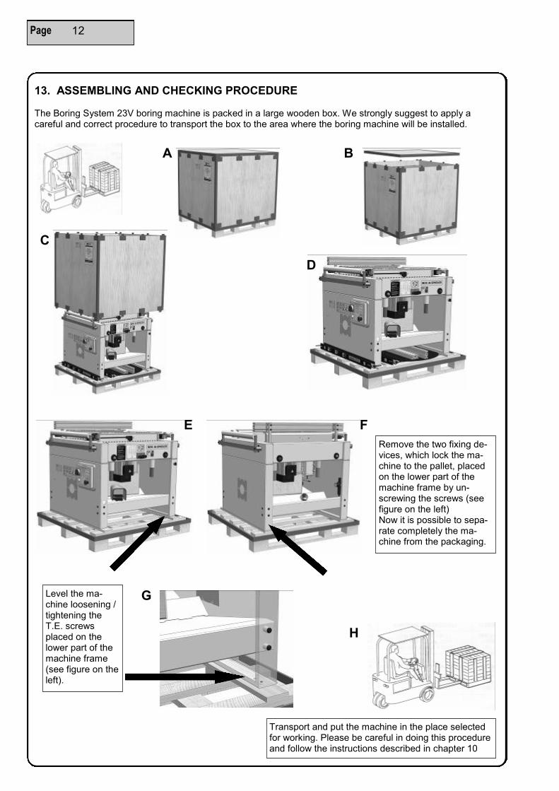
13. ASSEMBLING AND CHECKING PROCEDURE The Boring System 23V boring machine is packed in a large wooden box. We strongly suggest to apply a careful and correct procedure to transport the box to the area where the boring machine will be installed.
Remove the two fixing de-vices, which lock the ma-chine to the pallet, placed on the lower part of the machine frame by un-screwing the screws (see figure on the left) Now it is possible to sepa-rate completely the ma-chine from the packaging.
Transport and put the machine in the place selected for working. Please be careful in doing this procedure and follow the instructions described in chapter 10
Level the ma-chine loosening / tightening the T.E. screws placed on the lower part of the machine frame (see figure on the left).
A B
C
D
E F
G
H

Page 13
The packaging contains also the long fence group, clamping unit, clamp holder support and a cardboard box with some other accessories inside, as shown in the figure below.
The box contains the following accessories:
Dowel hole boring machine use and maintenance manual
Wrenches Kit n° 6 clamping unit
n° 4 Movable stop unit
n° 1 handle
n° 8 long fence pins
n° 4 lever M8x20
n° 4 kasher
n° 4 screw vtstei M8x20
Remember to assemble the long fence group and the movable stops following the procedure de-scribed in chapter 15.6
ATTENTION
Machine connection: we strongly suggest to
carefully follow the procedures described in chapter 16
Drilling set-up procedure:
carefully follow the procedures described in chapter 17
The next step consists of machine con-nection to:
Electric power supply (see chapter 15.1 )
Pneumatic power supply ( see chapter 15.2 )
Pneumatic power supply connection point
Electric power supply connection point

14. WORKING AREA To use the machine properly, the areas indicated in the picture below must be left free.
Page 14
Never leave the machine unattended when connected to the electrical power supply
15. ASSEMBLY AND PRELIMINARY PREPARATION FOR SET UP The machine is delivered partially assembled, so it is necessary to mount all those parts left not assembled for packaging reasons. The buyer must verify that all the machine parts are safe and not damaged after transportation, before going on with assembling. In particular we suggest to verify the most delicate parts, as electrical or mechanical components, pneumatic tubing or the safety protection devices of the machine itself. After assembling, it is necessary to clean all surfaces from protective oil so that the working pieces remain clean during working operations. SAWDUST REMOVAL The removal of sawdust and wood scrap, has to be effected in accordance to the current rules of the country where the machine is installed. We suggest to ask the qualified body of the country where the machine is installed for the rules concerning this removal to know exactly how to behave properly.
16. MACHINE CONNECTION TO EXTERNAL POWER SUPPLY
After machine assembling and installation, connect it with:
Electrical power supply
Pneumatic power supply
Dust suction system
ATTENTION: THE MACHINE IS DELIVERED WITHOUT EXHAUST SYSTEM. THE USER HAS TO INSTALL A PROPER EXHAUST FAN DEPENDING ON THE TYPE OF USE, THE MATERIAL AND THE TIMING OF USE OF THE MACHINE. THIS SYSTEM HAS TO KEEP THE DUST CONCENTRACTION BELOW THE VALUE ALLOWED BY THE LAW OF THE COUNTRY WHERE THE MACHINE IS INSTALLED.

16.2 PNEUMATIC CONNECTION
1) Connect the machine to the compressed air system and make sure that the connection tube is compatible with the one provided alongside the machine itself and located on the lubrication-filter-regulator unit at the back of the machine, in the lower right-hand side. Working pressure should range between 6 and 7 bar. 2) The lubrication-filter-regulator unit is made upby: A) A filter, whose function is to purify air from dust and humidity that might damage the valves or gaskets in pneumatic cylinders. B) A regulator that adjusts compressed air working pressure by keeping this value within the above-mentioned limits. C) A lubricator that puts a determined amount of oil into the system to lubricate cylinders, valves, gaskets and moving parts.
Page 15
16.1 CONNECTION TO ELECTRICAL POWER SUPPLY To gain access to the machine electric system, open the main board door by loosening the screws on the front of it. We recommend not to connect the machine to the electrical power supply until it is not correctly placed in the right place. Before connecting the machine to the electrical power supply, it is necessary to ver-ify that the electrical system corresponds to the following necessary power and safety requirements:
Grounded equipotential electrical system
Presence of fuses or protection switches against short circuits on every conducing cable R-S-T, except the grounded one
The electrical power system must be in conformity with CEI 64.8 (CENELEC HD 384, IEC364-4-41) rules
Voltage and frequency for the motors are specified on the plates placed on them
Connect the power supply cable to R-S-T terminals
Automatic protection devices installed upstream respect to the machine; they have to be coordinated to guarantee the automatic break according to above mentioned rules.
The electrical connection is done by three-phase plug (or single-phase plug, depending on the panel). The cable for ground connection is yellow-green. The tolerance of admissible voltage is +/-10% When voltage is applied to the electrical power supply, check that the spindles rotation direction is the one written in the plate placed on the head (Black=Right; Red=Left). If the rotation direction does not match the one impressed in the plate, please invert the connection cables to three phase power supply. For any information please see the electrical diagrams included in this manual.
Attention: we strongly recommend that the connection to the electrical power supply is done by technical qualified personnel only.
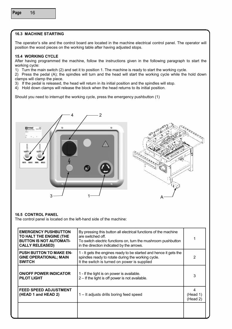
EMERGENCY PUSHBUTTON TO HALT THE ENGINE (THE BUTTON IS NOT AUTOMATI-CALLY RELEASED)
By pressing this button all electrical functions of the machine are switched off. To switch electric functions on, turn the mushroom pushbutton in the direction indicated by the arrows.
1
PUSH BUTTON TO MAKE EN-GINE OPERATIONAL; MAIN SWITCH
1 - It gets the engines ready to be started and hence it gets the spindles ready to rotate during the working cycle. It the switch is turned on power is supplied
2
ON/OFF POWER INDICATOR PILOT LIGHT
1 - If the light is on power is available. 2 – If the light is off power is not available.
3
FEED SPEED ADJUSTMENT (HEAD 1 and HEAD 2)
1 – It adjusts drills boring feed speed 4
(Head 1) (Head 2)
16.5 CONTROL PANEL The control panel is located on the left-hand side of the machine:
16.3 MACHINE STARTING The operator’s site and the control board are located in the machine electrical control panel. The operator will position the wood pieces on the working table after having adjusted stops. 15.4 WORKING CYCLE After having programmed the machine, follow the instructions given in the following paragraph to start the working cycle: 1) Turn the main switch (2) and set it to position 1. The machine is ready to start the working cycle. 2) Press the pedal (A); the spindles will turn and the head will start the working cycle while the hold down clamps will clamp the piece. 3) If the pedal is released, the head will return in its initial position and the spindles will stop. 4) Hold down clamps will release the block when the head returns to its initial position. Should you need to interrupt the working cycle, press the emergency pushbutton (1)
Page 16
4
3 1
2
A

17.4 HOW TO ADJUST SPINDLEHEAD PARALLELISM To adjust head parallelism to reference stop operate alternatively on the screws (1) and screw nuts (2) located on the spindlehead back plate after having partially unscrewed the screws (3).
17.1 DISCONNECTING PROCEDURE Before starting any maintenance intervention on the machine, follow this procedure: Make sure the machine is in a suitable position to carry out the needed intervention. After having fastened the machine mechanically in this position, disconnect the machine from power supply and pneumatic system. Make sure the machine is not connected to any other energy supply and that no residual power is left. It is essential that this procedure is carried out by a single person only, who will then have to make the state of the machine known by attaching a visible sign. 17.2 PREVENTIVE CHECKS Make sure the area surrounding the machine is neat and clean and that no working scraps are left around, such as saw dust and wood pieces. Make sure all safety and protection devices are in place, in good working order and ready for the machining that have to be carried out.
17. CHECKS AND ADJUSTMENTS
17.3 BORING DEPTH To carry out the required boring, follow this procedure: A) Insert suitable drills in the desired position on the spindleheads (A) – (B). B) To set boring depth do as follows: once the reading the digital counter (1), it is possible to set (no calcula-tion is needed) the actual boring depth value. Usually use a scrap wood piece to test the machine settings be-fore boring a good piece of wood. For references of drilling depth to see the detail (2)
Page 17
WE ADVISE YOU TO DISCONNECT THE MACHINE FROM POWER SUPPLY AND FROM THE PNEUMATIC SYSTEM WHENEVER YOU NEED TO SERVICE THE MACHINE OR TO RE-PLACE DAMAGED OR WORN PARTS. FOLLOW THE PROCEDURES INDICATED BELOW AND PAY ATTENTION TO THE ADVICE GIVEN IN PARAGRAPH 6 OF THIS MANUAL
DETAIL 2
3 3 2 1
2
1

17.5 HEAD POSITIONING FOR LINE BORING POINT 1: to position spindle heads from zero position (A reference stop), do as follows: Position counter of head n°1 at desired height by operating on (B) crank and likewise set height of head n° 2 by operating on (C) crank. Make sure the heights correspond to heights of piece to be bored. POINT 2: insert the chosen drills on the spindles and monitor the direction of rotation of each spindle. POINT 3: set holes depth by operating on the devices of each head (refer to paragraph 16.3). HOW TO POSITION THE STOP TO START THE WORKING CYCLE This boring machine comes with an extension fence with millimetric scale related to drills, which makes it pos-sible to determine the starting edge for line boring. Position the extension fence stops in the predetermined points, taking into account piece height. Positions can by obtained by calculating the overall distance from one point to the other or by using instruments. The extension fence can be equipped with a separate instrument (Fixed gauge) to bore longer rows of holes than the ones the boring machine can usually bore. Also refer to paragraph 17.6 – HOW TO USE REFERENCE PIN. HOW TO POSITON HOLD DOWN CLAMPS Once the machine is ready, hold down clamps units must be positioned exactly over the boring points before starting boring operations. To position hold down clamps manually move the bars (A+B) in the desired position and lock them by clamping the handles (C). Hold down clamps are then laid on the piece to be bored by oper-ating on each handle (D). BORING OPERATIONS Position the piece to be bored on the working table and lean it against references. Make sure electric and pneumatic connections are operational. By pressing the pedal (E) it is possible to simultaneously lock the piece into position, start the engines and feed drills at working speed. Each time you reset your boring ma-chine, it is advisable to simulate a working cycle with a scrap wood panel to make sure size is correct and that the machine is in good working order, without damaging a good wood panel.
Page 18
“ CAUTION: DANGER “ CAREFULLY FOLLOW THE PROCEDURE DESCRIBED BELOW

19. SERVICING 19.1 ROUTINE SERVICING
19.4 EXTRAORDINARY SERVICING
Make sure electrical system is safe.
Check clamping of mechanical components.
Check lubricating oil level in air-filtering unit and refill if necessary.
Make sure the machine is lubricated regularly.
Check air pressure. Line feed must be at 6 bar.
Check condensate level: condensate and compressed air impurities settle in the transparent sump in the air-purification system.
Make sure spindleheads are lubricated.
CAUTION – SLIPPING DANGER! While cleaning the working area, mind working scraps and liquids on the floor around the machine, since they might cause the operator to slip. 19.2 MACHINE CLEANING (DAILY) The machine and the working area must be kept clean from wood scraps or any other object that might ham-per the working cycle or might prevent the operator from easily reaching the machine itself. The machine must be cleaned daily. Make sure that material that is not needed to operate the machine cannot accumulate on the machine itself, thus preventing the machine from functioning safely and jeopardising the operator dur-ing the every-day working cycle. 19.3 RAILS CLEANING (WEEKLY) Rails and slide shafts must be kept clean from working scraps since these scraps might hamper movements of the machine and damage its performance. Do not use detergents or lubricants. ELECTRICAL CABLES CHECK: Monitor electrical cables condition. Make sure they are not worn out or abraded.
ADEQUATE SERVICING IS A FUNDAMENTAL FACTOR IN GUARANTEEING LONGER LIFE TO THE MACHINE AND TO KEEP THE MACHINE ITSELF IN OPTIMAL WORKING ORDER. ALL MAINTENANCE OPERATIONS MUST BE CARRIED OUT WHILE THE MACHINE IS SWITCHED OFF. ALWAYS WEAR PROTECTIVE GLOVES AND GOGGLES.
18. WOODWORKING EXAMPLES
17.6 HOW TO USE REFERENCE PIN TO BORE SETS OF HOLES IN A ROW (optional) As it can be complicated to use the extension fence to bore sets of holes rows on large pieces, our boring machines can be equipped with reference devices to be positioned on the machine sides. Aligned with the drills at a multiple distance (32-mm system), the pin (1) is a rapid and safe reference to carry out this type of boring. When the reference pin is not used, it fits into a slot under the table. To resume piece boring operations, the reference pin can be used once again by turning the knob (2) to unlock the spring that allows the reference pin to come out. The reference pin has to be inserted into one of the previously bored holes to make it possible for another series of holes row at con-stant pitch to be bored (paragraph 17).
Page 19
2) Boring for hinge slot, performed by drills with max diameter 35 mm, is to be executed only by
spindles no. 0 , 9 right and 9 left, corresponding to special spaces made in the rack.

POSSIBLE CAUSE WHAT TO DO
A. Drill is not clamped correctly B. Drills are worn C. Piece to be worked is not clamped cor-rectly
- Check clamping. If it is correct call service intervention. - Replace or call technical service - Check hold down clamps, hold down clamps gaskets and working pressure
20.3 HOLE IS NOT PRECISE
POSSIBLE CAUSE WHAT TO DO
A. Possible breakage in -gears and/or keys Transmission joint
- Replace (call technical service)
20.1 DRILLS ARE NOT TURNING
21. PROBLEMS THAT MIGHT OCCUR DURING MACHINE WORKING CYCLE 21.1 DRILLS LEAVING SCORCH MARKS This problem might occur if the piece is not positioned correctly on the table, if drills are worn or are turning in the opposite direction. 21.2 BORED PIECES ARE NOT PARALLEL TO STOP This problem might be due to the fact that the drills are not parallel to reference stop. Check head position to stop and make sure drills line in head 1 and 2 is parallel. 21.3 HOLD DOWN CLAMPS CANNOT CLAMP WOOD PIECE If hold down clamps cannot clamp pieces, check air pressure and connection pipes. To solve these problems, we suggest that you contact MAGGI Post-sale Assistance Service or your local dealer.
22. A. NOISE LEVEL Assuming the machine is functioning properly and that tool balancing and sharpness are correct, noise emis-sions can vary according to the material being worked, to drills diameter and to boring depth. Length of time operators are expected to stay close to the machine can vary over the 8-hour working day. Other factors play a role in determining the exposition level, such as surrounding environment and other sources of noise as well as the presence of other machines nearby. We advise you to inform operators about risks resulting from a long exposition to noise and, if necessary, provide them with suitable individual protection devices. The acoustic pressure level detected with a class-1 integrating noise meter at operator’s working position is 76.1dB (A). This measurement has been carried out in compliance with ISO 3745 standard. During this measurement, the ma-chine was functioning at steady state as far as pressure and speed were concerned, and was drilling a wooden shaving panel with PVC covering. The measurement has been carried out at a 1.5-meter height in front of the machine at the operator’s working location. The following reference measurements have been obtained by fol-lowing the same procedure: Acoustic pressure level in Atm. dB(A):78.3 Acoustic power level dB(A):93.3
22. B. DUST EMISSIONS These are the results of a test carried out to determine the level of dust emissions during a non-stop working hour, while a 20 mm-thick fir panel with PVC covering was being bored. Dust emissions amounted to 13.9 mg/N cu.m at operator’s working location, which is at a 1.5-meter height in front of the machine.
20.2 ENGINE IS RUNNING BUT DRILLS ARE NOT TURNING
POSSIBLE CAUSE WHAT TO DO
A - The engine not running B - The engine is burnt out
- Press the engine operational button - Release emergency pushbutton and/or check fuses - Check air pressure (to switch pressure switch on) - Replace the engine
20. COMMON FAILURES - CAUSES AND SOLUTIONS Some failure causes can be eliminated by the operator himself, while others failures need qualified personnel intervention.
CAUTION: BEFORE CARRYING OUT ANY INTERVENTION YOU MUST STRICTLY FOLLOW THE MACHINE CUTTING-OFF PROCEDURE DESCRIBED IN CHAPTER 16.
Page 20

24. ELECTRICAL SCHEME
23.1 HOW TO ADJUST AUTOMATIC PRESSURE Adjust machine pressure at a value ranging from a minimum value of 6 bar to a maximum of 8 bar with the knob located at the back of the machine, in the lower right-hand side and check pressure on the pressure gauge.
23. PNEUMATIC SCHEME
I.G.: main switch; C1/2: engine counter; PR: air pressure; M1/2: driving shaft rotation; F: main fuse.
24.1. PUTTING THE MACHINE OUT OF COMMISSION
If the machine has to be put out of commission, the following instructions will have to be followed strictly so as to guarantee people’s safety and to protect the environment around the machine. Therefore, after disconnecting the machine it is advisable to: - Disassemble drills and put them in a suitable container, where they will be stored and protected from dam-age. - Disassemble electrical, pneumatic and hydraulic components so that they can be re-used after an inspection or an overhaul. - Empty oil out of hydraulic gearcase without spilling it into the environment. - Disassemble all metallic components in the machine and divide them into separate groups according to material. - Call a firm specialised in material regeneration and disposal (solid and liquid materials).
Page 21

Page 22
NOTES

COUPON TO BE FORWARDED TO THE MANUFACTURER
GUARANTEE AND LOOK-OVER COUPON
Model...……………………………………..Serial number…………………………………………...
Name……………………………………………………………………………………………………………..
Address…………………………………………………………………………………………………………..
ZIP Code…………………………………...City………………………………………………………………
Date of purchase…………………………. Dealer…………………………………………………………...
Owner’s signature
…………………………………………..
The purchaser states to accept all the terms of guarantee and to have checked the machine to work well
25. GUARANTEE CERTIFICATE
The machine has been built according to technological and safety criteria and has been checked in our fac-
tory before being forwarded.
MAGGI ENGINEERING guarantees machine working and quality in agreement with law rules, for a period of
12 months. Improper use and incorrect maintenance, not following the rules contained in this manual, as
well as adjustments or modifications not approved by the manufacturer, cancel all the terms of guarantee.
The conditions of guarantee about the correct working of the machine are strictly connected to the respect of
all the indications described in the
USE AND MAINTENANCE MANUAL
The free replacement of any parts found to be faulty is done only after having checked that the machine had
been properly used.
Claims and guarantee interventions request are accepted only against presentation of the machine number
engraved into the identification plate.
Upon receipt of the machine carefully check that packaging is safe and not damaged. Except for different
agreement, the manufacturer is not responsible for any damages done during transport.
In case of evident damages on packaging, we suggest to contact immediately the carriers. Our firm will be
available to give the necessary support.
Page 23

Page 24
Send to:
Sales and technical Assistance
Via delle Regioni n°299
50052 CERTALDO (Fi) ITALY
NOTES

Page 25
26. SPARE PARTS CATALOGUE
POS. CODE PART NAME QUANTITY
1 26405000 FRAME GROUP 1
2 26405100 TABLE GROUP 1
3 26405500 HOLD DOWN CLAMPS UNIT 1
4 26405700 FRONT HEAD GROUP 1
5 26405701 REAR HEAD GROUP 1
6 26401900 REFERENCE PIN UNIT 1
7 26401800 LONG FENCE GROUP 1
7
1
4
5
3
2
6

Page 26 26405000
FRAME GROUP

Page 27 26405000
FRAME GROUP
POS. CODE PART NAME QUANTITY
1 40000030 PLATE 3M 68x46 3690-906 1
2 36405850 REFERENCE PIN PLATE 2
3 36405031 BS46 SET-UP PLATE 1
4 36405023 PLATE BS46 1
5 36405015 DRILLING DEPTH PLATE BORING 46 1
6 36405014 LONG ROLLER HOLDER GUIDE 4
7 36405013 ROLLER BEAM 2
8 36405012 BOCCOLA_PORTAR._46_ITG_2006 4
9 36405001 BEAM 1
10 36401086 TANK 1
11 36401085 SUCTION DUCT 1
12 36401084 LH SIDE PANEL 1
13 36401082 RH SIDE PANEL 1
14 36401014 FRAME SPACER 8
15 36401011 COUNTER PLATE 1
16 36251005 ELECTRIC PANEL GFE 1
17 36054032 ELECTRIC PANEL PLATE 1
18 36053002 COVER 1
19 36050032 FOOT 4
20 36050011 PRESS NUT 16
21 36050005 PLATE WARNING 100x150 1
22 00140603 SCREW STEI M6X8 P.C. UNI-5927 9
23 00018627 SCREW TBCEI M10X16 ISO-7380 ZINC. 8
24 00018612 SCREW VTBCEI M10 x 40 8
25 00018523 PLAIN WASHER Ø13 UNI-6592 ZINC. 10
26 00018522 PLAIN WASHER Ø10 UNI-6592 ZINC. 1
27 00018520 PLAIN WASHER Ø6 UNI-6592 ZINC. 16
28 00018507 NUT M12 UNI-5588 6S ZINC. 10
29 00018461 SCREW TBCEI M6X25 ISO-7380 ZINC. 16
30 00018417 SCREW TE M 12X30 UNI 5739 ZINC. 6
31 00018289 SCREW TCEI M4X40 UNI-5931 ZINC. 2
32 00015816 FITTING PNMX 25 250418 2
33 00015815 FITTING PNMX 15 150418 2
34 00015651 "T" FITTING 1
35 00015650 FITTING ART.34 340818 1
36 00015260 PNEUMATIC PEDAL KPM 1
37 00015233 FILTER REDUCER PNMX 1/4 20 08 TP 1
38 00015229 FLOW REGULATOR G1 8-COD-6-01-18-NE 3
39 00015224 FLOW REGULATOR G1-4 PNMX 2
40 00015221 PRESSURE SWITCH 1_8 COD.PMN10A 1
41 00015219 MANOMETER M40 1
42 00005110 SCREW TC Ø 3,9 x 19 ZINC UNI 6954 4
43 00005094 EMERGNCY PUSHBUTTON 020PTAARK 1
44 00005093 LINE LAMP (21-23-29-35-46) 1
45 00005091 GENERAL SWITCH 1
46 00004111 BALL SP15LBD 22
47 00004068 CONNECTING PIPE PNMX 07 070400 2
48 00004067 REDUCER PNMX 08 08 04 1
49 00004065 “T” FITTING ART_05_4 1
50 00004013 SELETCTOR PNMX 104 32 6 30 LC 2
51 00003033 BALL SLEEVE KH2540PP 8
52 00001124 BLACK SHEAT BTM25 1,5 meters
53 00001114 PNMX FITTING L 04 4 1
54 00001110 FITTING -L-ART-04-8 4
55 00001108 FITTING ART. 015-8-1_4 2
56 00001107 FITTING ART.02-8-1_8-DIR-FEM 2
57 00001104 CONNECTING PIPE ART. 07-8 9
58 00001102 FITTING R5_8_T 3
59 00001101 FITTING ART.01-8-1_8 6
60 00001013 FITTING ART.01-8-1_4 2
61 00000102 NUT M4 UNI-5588 6S BRUN. 2
62 * SEEGER RING ZA25 4

Page 28 26405100
TABLE GROUP
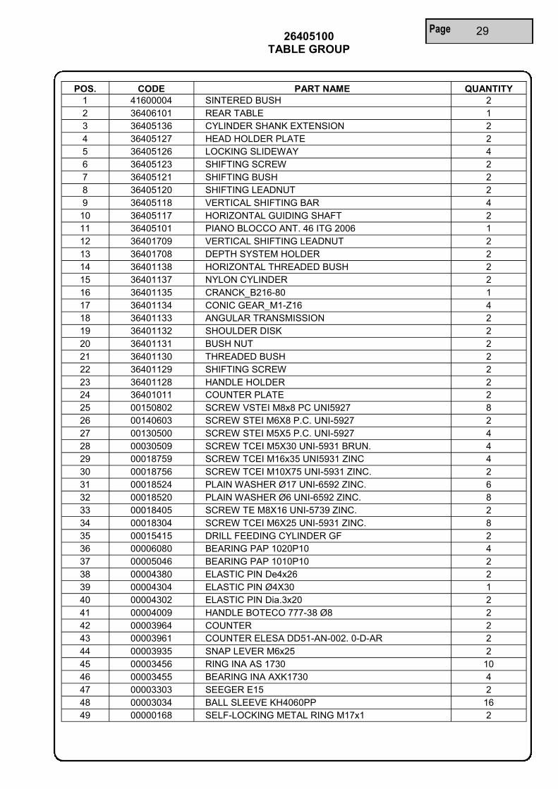
Page 29 26405100
TABLE GROUP
POS. CODE PART NAME QUANTITY
1 41600004 SINTERED BUSH 2
2 36406101 REAR TABLE 1
3 36405136 CYLINDER SHANK EXTENSION 2
4 36405127 HEAD HOLDER PLATE 2
5 36405126 LOCKING SLIDEWAY 4
6 36405123 SHIFTING SCREW 2
7 36405121 SHIFTING BUSH 2
8 36405120 SHIFTING LEADNUT 2
9 36405118 VERTICAL SHIFTING BAR 4
10 36405117 HORIZONTAL GUIDING SHAFT 2
11 36405101 PIANO BLOCCO ANT. 46 ITG 2006 1
12 36401709 VERTICAL SHIFTING LEADNUT 2
13 36401708 DEPTH SYSTEM HOLDER 2
14 36401138 HORIZONTAL THREADED BUSH 2
15 36401137 NYLON CYLINDER 2
16 36401135 CRANCK_B216-80 1
17 36401134 CONIC GEAR_M1-Z16 4
18 36401133 ANGULAR TRANSMISSION 2
19 36401132 SHOULDER DISK 2
20 36401131 BUSH NUT 2
21 36401130 THREADED BUSH 2
22 36401129 SHIFTING SCREW 2
23 36401128 HANDLE HOLDER 2
24 36401011 COUNTER PLATE 2
25 00150802 SCREW VSTEI M8x8 PC UNI5927 8
26 00140603 SCREW STEI M6X8 P.C. UNI-5927 2
27 00130500 SCREW STEI M5X5 P.C. UNI-5927 4
28 00030509 SCREW TCEI M5X30 UNI-5931 BRUN. 4
29 00018759 SCREW TCEI M16x35 UNI5931 ZINC 4
30 00018756 SCREW TCEI M10X75 UNI-5931 ZINC. 2
31 00018524 PLAIN WASHER Ø17 UNI-6592 ZINC. 6
32 00018520 PLAIN WASHER Ø6 UNI-6592 ZINC. 8
33 00018405 SCREW TE M8X16 UNI-5739 ZINC. 2
34 00018304 SCREW TCEI M6X25 UNI-5931 ZINC. 8
35 00015415 DRILL FEEDING CYLINDER GF 2
36 00006080 BEARING PAP 1020P10 4
37 00005046 BEARING PAP 1010P10 2
38 00004380 ELASTIC PIN De4x26 2
39 00004304 ELASTIC PIN Ø4X30 1
40 00004302 ELASTIC PIN Dia.3x20 2
41 00004009 HANDLE BOTECO 777-38 Ø8 2
42 00003964 COUNTER 2
43 00003961 COUNTER ELESA DD51-AN-002. 0-D-AR 2
44 00003935 SNAP LEVER M6x25 2
45 00003456 RING INA AS 1730 10
46 00003455 BEARING INA AXK1730 4
47 00003303 SEEGER E15 2
48 00003034 BALL SLEEVE KH4060PP 16
49 00000168 SELF-LOCKING METAL RING M17x1 2

Page 30 26405500
HOLD DOWN CLAMPS UNIT
00001123 BLACK SPIRAL PIPE TR 8x6

Page 31 26405500
HOLD DOWN CLAMPS UNIT
POS. CODE PART NAME QUANTITY 1 49900051 CROSS BEAM CLAMPING WASHER 8
2 36402506 LH HOLD DOWN CLAMPS FRAME 1
3 36402505 RH HOLD DOWN CLAMPS FRAME 1
4 36401504 CROSS BEAM FOR DOUBLE 4
5 36051502 SPACER BLOCK 4
6* 26054501 HOLD DOWN CLAMPS UNIT SUBGROUP 6
7 00018606 SCREW VTBCEI M8x25 4
8 00018602 SCREW TBCEI M10X30 ISO-7380 ZINC. 6
9 00018520 PLAIN WASHER Ø6 UNI-6592 ZINC. 8
10 00018503 NUT M10 UNI-5588 6S ZINC. 6
11 00018500 NUT M6 UNI-5588 6S ZINC. 10
12 00018400 SCREW VTE M6x12 2
13 00009083 SCREW TBCEI M6X60 ISO-7380 ZINC. 8
14 00005041 FISCHER SUPPORT SCH-8-12-GR 2
15 00004070 FITTING PNMX T030800 2
16 00004025 RELEASE LEVER M8 L50 4
17 00001126 BLACK SPIRAL 6
18 00001110 FITTING -L-ART-04-8 4
19 00001104 FITTING ART. 07-8 2
20 00001102 FITTING R5_8_T 4
21 00000051 SCHNOR WASHER Ø10 12
* = for detailed information on part code number 26054501 - HOLD DOWN CLAMPS UNIT SUBGROUP please see the following pages

Page 32 26054501 - HOLD DOWN CLAMPS UNIT SUBGROUP

Page 33 26054501 - HOLD DOWN CLAMPS UNIT SUBGROUP
POS. CODE PART NAME QUANTITY 1 49981043 PISTON SHAFT 1
2 49972052 PISTON 1
3 49972045 CLAMPING RING NUT 1
4 49972040 CYLINDER 1
5 49971051 INFERIOR HEAD 1
6 49970146 SMALL PISTON SPRING 1
7 49970053 PISTON SPRING 1
8 49970048 THREADED CYLINDER 1
9 49970047 WEDGE SHAPED PISTON 1
10 49970042 PISTON CYLINDER COVER 1
11 49901089 HEAD PIPE 1
12 49901088 SLIDING HEAD 1
13 49900095 NYLON ROUND 1
14 32700000 STICKER 1
15 00120404 SCREW STEI M4X4 P.P. UNI-5923 1
16 00018439 SCREW TSPEI M4x8 UNI-5933 ZINC. 1
17 00005103 SCREW AUT. 3.9x9.5 zinc.6955 1
18 00003120 BOTECO HANDLE119-32 M6 1
19 00001250 FITTING ART_06_8_1-4_CIL 1
20 00001121 O-RING PNEUMAX COD R-1502.50.5 1
21 00001120 PACKING PISTON 1
22 00000118 NUT M14 UNI-5589 6S BRUN. 1

Page 34 26405700 / 26405701
FRONT HEAD GROUP / REAR HEAD GROUP t
he F
RO
NT
HE
AD
GR
OU
P a
nd the R
EA
R H
EA
D G
RO
UP
diffe
rs f
or
the H
EA
D C
OV
ER
only
:
FR
ON
T H
EA
D G
RO
UP
- p
art
code n
um
ber
36405700 n
am
ed H
EA
D C
OV
ER
23 x
46 F
RO
NT
HE
AD
RE
AR
HE
AD
GR
OU
P -
part
code n
um
ber
36405701 n
am
ed H
EA
D C
OV
ER
23 x
46 R
EA
R H
EA
D

Page 35 26405700 / 26405701
FRONT HEAD GROUP / REAR HEAD GROUP
POS. CODE PART NAME QUANTITY
1 36950210 ENGINE ROUND PLATE 1
2 36950209 MOTOR JOINT 1
3 36405704 HEAD BODY 23 1
* 4 - front 36405700 HEAD COVER 23 x 46 FRONT HEAD 1
* 4 - rear 36405701 HEAD COVER 23 x 46 REAR HEAD 1
5 36052710 23 PRESTIGE PLATE 1
6 36050711 NYLON JOINT 1
7 36001060 DRIVEN SPINDLE 22
8 36001059 DRIVING SPINDLE 1
9 36000063 BEARING SPACER 23
10 36000062 GEAR Z21 23
11 26405705 MOTOR M71-2T 230-400-50 HP 1,5 1
12 00130501 SCREW STEI M5X5 P.P. UNI-5923 23
13 00100614 SCREW STEI M6X20 P.P. UNI-5923 2
14 00040610 SCREW VTCEI M6x40 4
15 00018655 SCREW TCEI M8x75 UNI-5931 ZINC. 4
16 00018520 PLAIN WASHER Ø6 UNI-6592 ZINC. 1
17 00018500 NUT M6 UNI-5588 6S ZINC. 2
18 00018436 SCREW TE M6x8 UNI5739 ZINC 1
19 00018326 SCREW TCEI M6X80 UNI-5931 ZINC. 4
20 00018302 SCREW TCEI M6X10 UNI-5931 ZINC. 12
21 00005097 GASKET Øi 20 Øe 25,5 23
22 00005025 SPRING Ø4 L=9 23
23 00004103 BALL 1 / 8 23
24 00003703 GREASE NIPPLE 1
25 00003424 SKF BALL BEARING 6001 2RS1 46
26 00003337 SEEGER I 28 46
27 00003307 SEEGER E20 1
28 00003305 SEEGER E12 23
29 00000250 PARALLEL KEY 4x4x18 1
30 00000220 PARALLEL KEY 5X5X18 1
31 00000218 PARALLEL KEY 5X5X25 1
32 00000211 PARALLEL KEY 4x4x12 UNI-6604 A 23
33 00000042 SCHNOR WASHER Ø8 4
34 00000041 SCHNOR WASHER M6 8
35 00000037 WASHER PS Ø12X18X1 22
* = the FRONT HEAD GROUP and the REAR HEAD GROUP differs for the HEAD COVER only:
FRONT HEAD GROUP - part code number 36405700 named HEAD COVER 23 x 46 FRONT HEAD
REAR HEAD GROUP - part code number 36405701 named HEAD COVER 23 x 46 REAR HEAD
REAR HEAD GROUP
FRONT HEAD GROUP
BS46 TOP VIEW

Page 36 26401800
LONG FENCE GROUP

Page 37 26401800
LONG FENCE GROUP
26400606 MOVABLE STOP UNIT
POS. CODE PART NAME QUANTITY
1 49970077 LARGE SCREW ANCHOR 4
2 46050806 LH MILLIMETERS SCALE FOR EXTENSION FENCE 2
3 46050805 RH MILLIMETERS SCALE FOR EXTENSION FENCE 2
4 36401808 FRAME SPACER 2
5 36401807 CLAMP FOR EXTENSION FENCE 8
6 36401806 EXTENSION FRAME FOR DOUBLE 3
7 36401805 EXTENSION FENCE ATTACHMENT 2
8 26400606 MOVABLE STOP UNIT 4
9 00140602 SCREW STEI M6X8 P.P. UNI-5923 8
10 00060803 SCREW TCEI M10X20 UNI-5931 BRUN. 2
11 00018522 PLAIN WASHER Ø10 UNI-6592 ZINC. 2
12 00018521 PLAIN WASHER Ø8 UNI-6592 ZINC. 4
13 00018377 SCREW TCEI M8X40 UNI-5931 ZINC. 4
14 00003931 RELEASE LEVER M6x12 2
00008905 RIVET 16

Page 38 26401900 / 26401901 FRONT REFERENCE PIN UNIT / REAR REFERENCE PIN UNIT
( OPTIONAL )
00004013 PNMX SELECTOR 104 32 6 30 LC
00015815 PNMX FITTING 15 150418
00015816 PNMX FITTING 25 250418

POS. CODE PART NAME QUANTITY 1 36401906 REFERENCE PIN ASQUARE 1
2 00004041 PMX CYLINDER COD1503-25-10 1
3 36401905 SUPPORT 1
4 36401904 REFERENCE PIN 1
5 00001109 PNMX SILENCER 1 8 COD.60518 1
6 36401907 CLAMP 2
7 00006081 BEARING PAP 1610P10 1
8 00018297 SCREW VTCEI M5X12 UNI-5931 4
9 00018520 WASHER Ø6 UNI-6592 4
10 00018325 SCREW VTCEI M6X16 UNI-5931 2
11 00018302 SCREW VTCEI M6X10 UNI-5931 2
12 00001155 PNMX FITTING 01-4-1 8 1
-- 00001123 RILSAN PIPE Ø 8 2,5 Meters
Page 39 26401900 / 26401901 FRONT REFERENCE PIN UNIT / REAR REFERENCE PIN UNIT
( OPTIONAL )

Page 40
27. SPARE PARTS REQUEST
ATTENTION! FILL IN DETAILS THIS FORM
Customer
…………………………………………………………..
Address
…………………………………………………………..
…………………………………………………………..
Date …………………………………………………….
Telephone number
…………………………………………………………..
Telefax
…………………………………………………………..
NOTE
………………………………………………………………………………………………………………………………
………………………………………………………………………………………………………………………………
………………………………………………………………………………………………………………………………
N.B.: Please attach a copy of each table where the requested part is.
MACHINE TYPE SERIAL NUMBER DELIVERY DATE
GROUP CODE CODE PART NAME QUANTITY


Maggi Engineering Via delle Regioni, 299
Woodworking machinery 50052 Certaldo ( Fi ) Italy
Tel. +39 0571 63541
Fax. +39 0571 664275
Sales
Spare parts
E mail
Internet
Development by MAGGI ENGINEERING
Tel. +39 0571 635420 Tel. +39 0571 635432 Tel. +39 0571 635405 Tel. +39 0571 635436 Tel. +39 0571 635422 Fax. +39 0571 664043
www.maggi-engineering.com
Certificate N.SA-190
Company with Social Accountability Management System Certificate SA8000

![Untitled-1 [] · CHOCOMILO; Bouillon - MAGGI CUBE, MAGGI CHICKEN, MAGGI CRAYFISH, MAGGI MIX'PY; and table water ... and marketing company](https://img.pdfslide.us/doc/110x75/5aedc9577f8b9a6625906f43/untitled-1-bouillon-maggi-cube-maggi-chicken-maggi-crayfish-maggi-mixpy.jpg)