Embed Size (px)
Citation preview
Pergamon
Int. J. Rock Mech. Min. Sci. & Geomech. Abstr. Vol. 33, No. I, pp. 53-69, 1996 Copyright © 1996 Elsevier Science Ltd
0148-9062(95)00029-1 Printed in Great Britain. All fights reserved 0148-9062/96 $15.00 + 0.00
Borehole Breakdown Pressure with Drilling Fluids II. Semi-analytical Solution to Predict Borehole Breakdown Pressure N. M O R I T A f
G . - F . FUH~:
A. D. B L A C K §
The fracture initiation and propagation experiments discussed in Part I revealed that three distinct zones exist around a fracture tip. They are the fracture process zone, the non-invaded and the dehydrated gel zone. These three zones significantly increase wellbore breakdown pressure and fracture propagation resistance under a relatively large in s i tu stress. With the assumption that wellbore pressure is sealed at the inlet o f the dehydrated mud zone, a semi-analytical model o f a fractured, inclined borehole is developed for a general plane strain condition. The model predicts that when drillingfluid is used as an injection fluid, borehole breakdown pressure is highly dependent on the formation Young's modulus, the in situ stress, the wellbore size, and type o f the drilling fluids, although conventional theories have not included all these.
N O M E N C L A T U R E
A = well radius plus fracture length B = well radius plus the fracture interval invaded
with drilling fluid c = fluid compressibility
C = specific heat q, Cb = rock matrix and bulk compressibilities E, v = elastic moduli
F I, F2, F3 = constants given in Table 1 G 1, G2, G3 = constants given in Table 1
H I, H2, H3, H4 = constants given in Table 2 K = thermal diffusion coefficient
Kc = fracture toughness Kf, KT = permeability, thermal diffusivity P, P . = pressure, well pressure
e f
e o w q =
Qr = r =
r =
r w
R r =
R m :
R t =
S, S1 =
pressure within a fracture pore pressure at the borehole surface pore pressure gradient around a borehole temperature gradient around a borehole radial coordinate r/rw well radius fracture radius up to the pressure sealing point the length of dehydrated mud around the fracture tip length of the fracture tip without mud inva- sion defined in Table 2
fDepartment of Mineral Resources Engineering, Waseda University, Ohkubo 3-4-1, Shinjuku, Tokyo, Japan.
~Conoco Inc., 1000 South Pine Street, Ponca City, OK 174602, U.S.A. §University Research Park, 400 Wakara Way, Salt Lake City, UT
84108, U.S.A.
RUMS ~3/,--E 53
I d =
T,T~= W=
WI, W2, W3, W4, Wp =
time dimensionless time defined in Appendix temperature, temperature at wellbore fracture width fracture widths corresponding to the hydro- static boundary stress, directional stress, borehole pressure, fracture surface pressure and pore pressure, respectively.
W m = fracture width at the sealing point with mud cake
W t = fracture width at the point which does not allow the mud invasion
W 0 = fracture width of a pre-existing fracture ~o = defined in Table 3 ct = thermal expansion coefficient
fl, 7 = r,/A, well angle a = radial stress
a o = tangential stress a z = axial stress
tYHi , Gh2 = in situ stresses (negative) tru, Ov = horizontal and vertical in situ stress
G I ~ GHI - - G I ~
(, r/= 2~/A/n, B/A p, # = fluid density, viscosity
~b = porosity
I N T R O D U C T I O N
A s t a n d a r d b o r e h o l e b r e a k d o w n ana lys i s uses t he
K i r s h ' s s o l u t i o n w h i c h p r o v i d e s the l inear e las t ic i ty
e q u a t i o n fo r a gene ra l p l a n e s t r a in c o n d i t i o n . B o r e h o l e
b r e a k d o w n p r e s s u r e is a s s u m e d to o c c u r w h e n the
m a x i m u m t a n g e n t i a l s t ress r e ach es the tensi le r o c k
s t r eng th . H o w e v e r , l a b o r a t o r y o b s e r v a t i o n s s h o w t h a t i f
54 MORITA et al.: BOREHOLE BREAKDOWN--SEMI ANALYTICAL SOLUTION
drilling fluid is used as a fracturing fluid, the borehole breakdown does not occur even if an initiated fracture propagates as much as 0.76-7.62 cm (0.3-3 in.) [up to 10 cm (4 in.) at rock boundary] for laboratory conditions and depending on the confining pressure, the solid content of drilling fluid and formation Young's modu- lus. The fracture extension pressure initially increases with fracture length but, when the drilling fluid starts penetrating into the fracture due to the enlarged fracture aperture, the fracture extension pressure reduces, result- ing in borehole breakdown. Since borehole breakdown pressure depends on the fracture width around the fracture tip, borehole breakdown pressure becomes de- pendent on the formatin Young's modulus, borehole size, confining pressure and the plugging capability of drilling fluid.
The Kirsh 2-D plane strain solution considers an inclined borehole problem by transforming the in situ stress into components with the z-axis coinciding with the borehole axis. The in-plane in situ stress components are axx, ayy, trxy and a=. The out-of-plane in situ stress components azx and azy affect the deformation in the z direction but they do not affect the deformation in the x y plane. In addition, the out- of-plane in situ stress components do not affect the tangential stress around a well. This fact significantly simplifies the general plane strain problem since if the two horizontal in situ stresses are equal, a mode I fracture is induced and propagates in the well azimuth direction and the width and propagation criterion are not affected by the out-of-plane in situ stresses. Hence, the stress intensity factor and width of the fracture induced along the well azimuth direction can be calcu- lated by a 2-D fracture model instead of a 3-D fracture model, although the problem itself is a general plane strain problem with a 3-D deformation.
To predict the borehole breakdown pressure observed in the laboratory scale and field scale wells, an analytical model to simulate a fracture extension around a bore- hole is needed. Since no analytical solution has been found for the stress intensity factor and fracture width for the crack from a borehole, an approximate solution is found by numerical experiments. First, a closed form solution is found for the fracture width and stress inten- sity factor for a planar crack without a borehole. Then, correction factors are added for the borehole effect such that the analytical equation asymptotically approaches the analytical solution without the borehole if the frac- ture becomes significantly large. The correction factors are determined by fitting to the results of the numerical experiments generated by a finite element model.
Parameter analysis for borehole breakdown pressure was conducted using the semi-analytical solution. The semi-analytical solution predicts the effects of Young's modulus, confining stress and plugging of drilling fluids on borehole breakdown. The results match with the laboratory results reported in Part I. The semi-analytical solution is used to study the field obser- vations of borehole breakdown pressures under various conditions.
SEMI-ANALYTICAL SOLUTION OF BOREHOLE BREAKDOWN PRESSURE
Figure 1 shows the boundary conditions to be solved. The well and part of the fracture (up to the sealing point of dehydrated drilling fluid) have pressure Pw and the pressure between the sealing point and the fracture front is set to equal to the pore pressure. Inclination of borehole, temperature and pore pressure effects are also taken into account. Among the loads (three in situ stresses, pore pressure, temperature, borehole pressure, pressure in cracks), only the in situ stress components include the out-of-plane stress components (out-of-plane in situ stress: axe, ayz in-plane in situ stress: axy, trxy, ayy, tr~z ) which may affect the stress intensity factor and the fracture width. Two- and three-dimensional finite el- ement meshes were constructed to study the out-of-plane stress effect as shown in Fig. 2. It was found that if the two horizontal in situ stresses are assumed to be equal or tr m = trn2, the out-of-plane in situ stress does not affect the fracture width and the stress intensity factor for the following reasons:
(A) A fracture initiated at the minimum tangential stress direction propagates as an in-plane fracture if O'HI = am. The fracture propagates as a mode I fracture propagation in the well azimuth direction.
(B) Numerical experiments showed that out-of-plane stresses did not affect the stress intensity factor and fracture width if the fracture propagates as mode I propagation. Only the stress normal to the fracture plane and stress perpendicular to the borehole control the fracture width and stress intensity factor.
The above two facts significantly simplify the calcu- lations of aperture and stress intensity factor for a stable fracture propagating from an inclined borehole since the stress normal to the fracture plane and the stress perpen- dicular to the borehole are given by the general plane strain solution. Note that if am is not equal to a m , the
A
Pressure sealing point
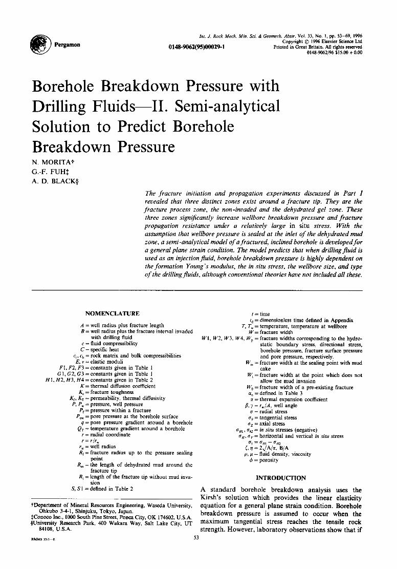
Fig. 1. Boundary condition for an inclined well with a fracture~a general plane strain problem.
MORITA et al.: BOREHOLE BREAKDOWN--SEMI ANALYTICAL SOLUTION 55
t
J
J
J
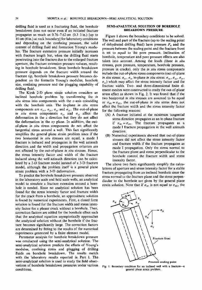
Fig. 2. Finite element mesh for a fractured borehole--2-D mesh (90 ° mesh) and 3-D inclined well mesh (180 ° mesh).
out-of-plane stress also affects the stress intensity factor and fracture width.
Let anl and tr m be in-plane, principal in s i tu stress given by
tr m = trH, grin = COS 2 7all + sin 2 )'try (1)
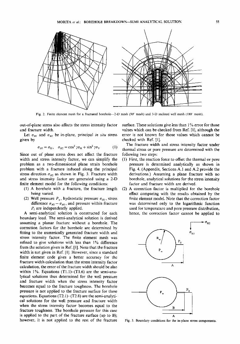
Since out of plane stress does not affect the fracture width and stress intensity factor, we can simplify the problem as a two-dimensional plane strain borehole problem with a fracture induced along the principal stress direction trn2 as shown in Fig. 3. Fracture width and stress intensity factor are generated using a 2-D finite element model for the following conditions:
(1) A borehole with a fracture, the fracture length being varied.
(2) Well pressure Pw, hydrostatic pressure tr m , stress difference tr m - am, and pressure within fracture Pf are independently applied.
A semi-analytical solution is constructed for each boundary load. The semi-analytical solution is derived assuming a planar fracture without a borehole. The correction factors for the borehole are determined by fitting to the numerically generated fracture width and stress intensity factor. The finite element mesh was refined to give solutions with less than 1% difference from the solution given in Ref. [1]. Note that the fracture width is not given in Ref. [1]. However, since a standard finite element code gives a better accuracy for the fracture width calculation than the stress intensity factor calculation, the error of the fracture width should be also within 1%. Equations (TI.1)-(T1.6) are the semi-ana- lytical solutions thus determined for the well pressure and fracture width when the stress intensity factor becomes equal to the fracture toughness. The borehole pressure is not applied to the fracture surface for these equations. Equations (T2.1)-(T2.8) are the semi-analyti- cal solutions for the well pressure and fracture width when the stress intensity factor becomes equal to the fracture toughness. The borehole pressure for this case is applied to the part of the fracture surface (up to B); however, it is not applied to the rest of the fracture
surface. These solutions give less than 1% error for those values which can be checked from Ref. [1], although the error is not known for those values which cannot be checked with Ref. [1].
The fracture width and stress intensity factor under thermal stress or pore pressure are determined with the following two steps: (1) First, the reaction force to offset the thermal or pore
pressure is determined analytically as shown in Fig. 4. (Appendix, Sections A. 1 and A.2 provide the derivations.) Assuming a plane fracture with no borehole, analytical solutions for the stress intensity factor and fracture width are derived.
(2) A correction factor is multiplied for the borehole effect comparing with the results obtained by the finite element model. Note that the correction factor was determined only to the logarithmic function used for temperature and pore pressure distribution, hence, the correction factor cannot be applied to
A
OH1
OH2
P0
A Fig. 3. Boundary conditions for the in-plane stress components.
56 M O R I T A et al.: BOREHOLE B R E A K D O W N - - S E M I A N A L Y T I C A L SOLUTION
(A)
~ ~ T(r)
(B) r D
Ect r ~ 2 f 1 rDTdrD_~.vct T T--V
a
Fig. 4. Equivalent fracture surface load to offset the temperature load: (A) borehole with a fracture under temperature field; and (B) equival-
ent fracture surface load.
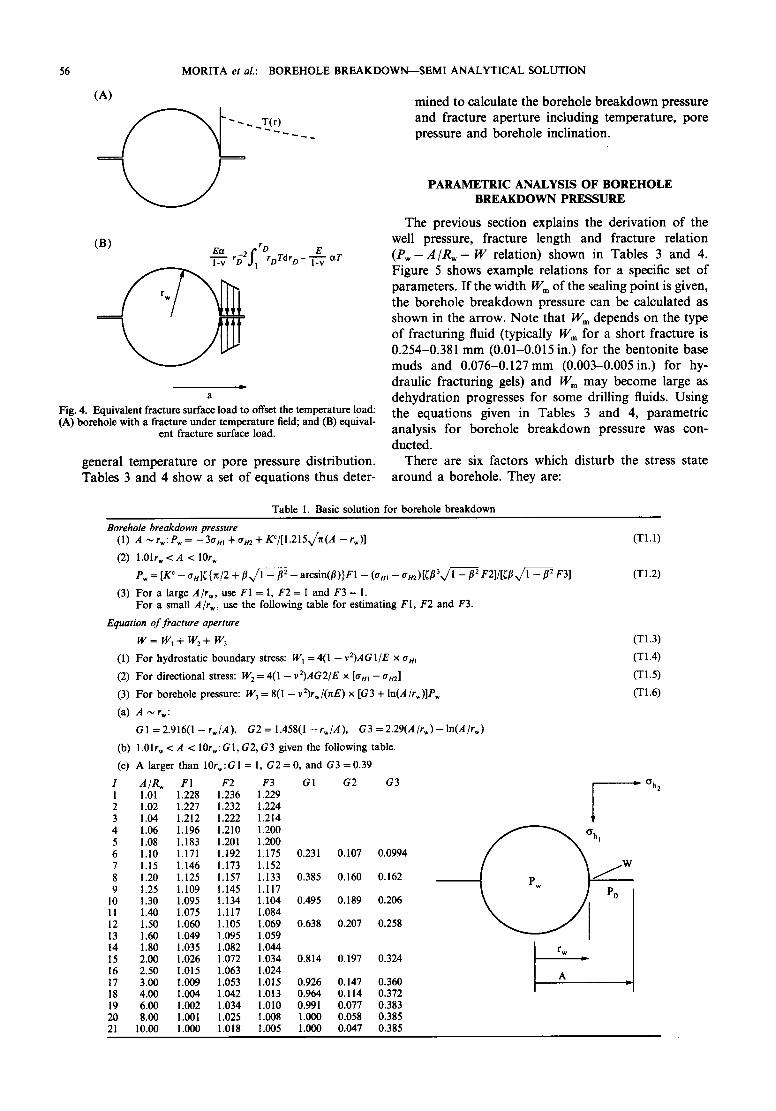
general temperature or pore pressure distribution. Tables 3 and 4 show a set of equations thus deter-
mined to calculate the borehole breakdown pressure and fracture aperture including temperature, pore pressure and borehole inclination.
PARAMETRIC ANALYSIS OF BOREHOLE BREAKDOWN PRESSURE
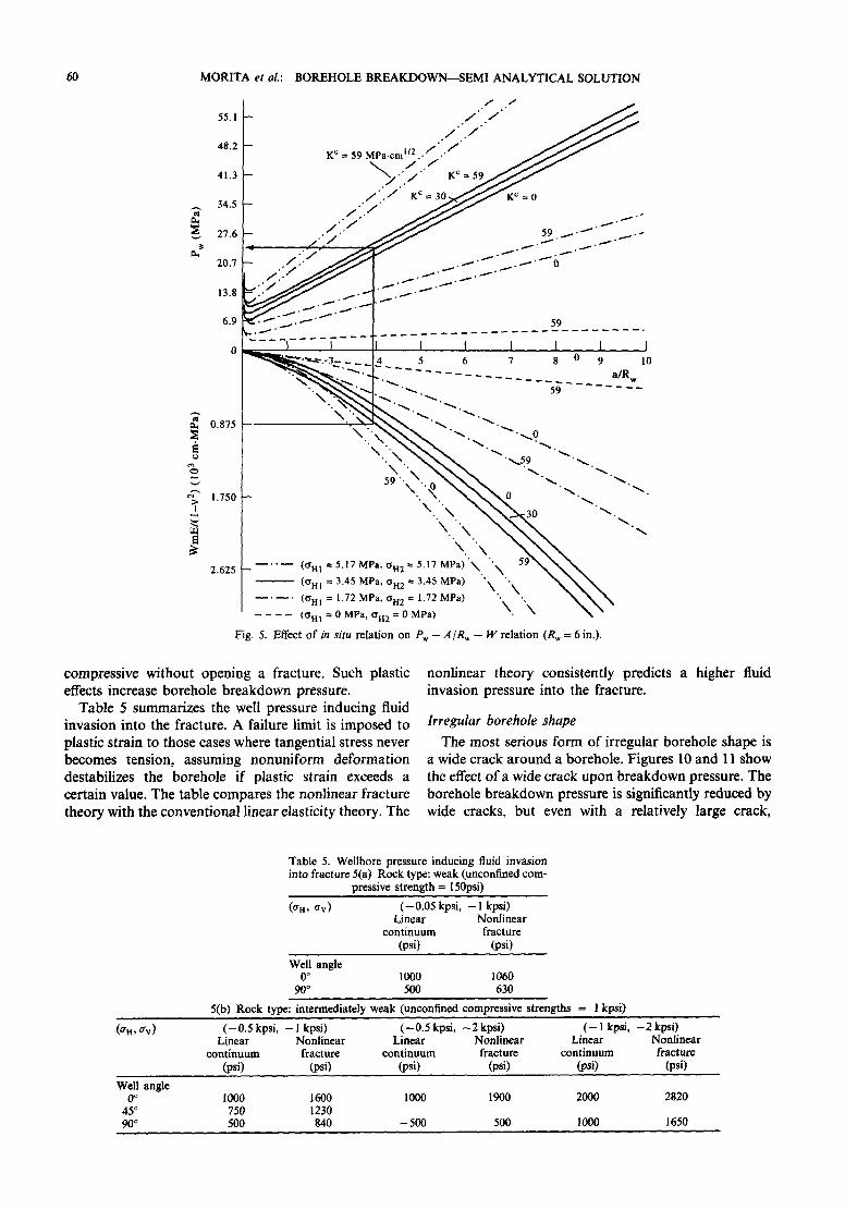
The previous section explains the derivation of the well pressure, fracture length and fracture relation (Pw- A / R w - W relation) shown in Tables 3 and 4. Figure 5 shows example relations for a specific set of parameters. If the width Wm of the sealing point is given, the borehole breakdown pressure can be calculated as shown in the arrow. Note that Wm depends on the type of fracturing fluid (typically Wm for a short fracture is 0.254-0.381 mm (0.01-0.015 in.) for the bentonite base muds and 0.076-0.127mm (0.003-0.005in.) for hy- draulic fracturing gels) and Wm may become large as dehydration progresses for some drilling fluids. Using the equations given in Tables 3 and 4, parametric analysis for borehole breakdown pressure was con- ducted.
There are six factors which disturb the stress state around a borehole. They are:
Table 1. Basic solution for borehole breakdown
Borehole breakdown pressure (1) A ~ rw: P~ = - 3 a m + a m + K¢/[1 .215v/ -~ -- r , )]
(2) 1.01r~ < A < 10r,,
Pw = [ K¢ -- an]( {n/2 + fl l % / / l ~ fl 2 - arcsin(fl)}F1 - (am - trm)[([33x/l -- [32 F 2 ] / [ ~ [ 3 ~ F3]
(3) For a large A/r w, use FI = 1, F 2 = 1 and F3 = 1. For a small A/rw, use the following table for estimating FI , F2 and F3.
Equation of fracture aperture
w = w, + w2 + w3
(1) For hydrostatic boundary stress: W I = 4 0 - v 2 ) A G 1/E x a m
(2) For directional stress: W 2 = 4(1 - v2)AG2/E x [am - am]
(3) For borehole pressure: W 3 = 8(1 - v:)rw/(rrE) x [G3 + ln(A/rw)]Pw
(a) A ~ r,,:
G l = 2 . 9 1 6 ( 1 - r w / A ), G 2 = 1 . 4 5 8 ( 1 - r w / A ), G 3 = 2.29(A/rw)-ln(A/rw)
(b) 1.01r W < A < 10rw:Gl, G2, G3 given the following table.
(c) A larger than 10rw:G1 = 1, G 2 = 0 , and G3 =0 .39
I A/R~ F1 F2 F3 G1 G2 G3 1 1.01 1.228 1.236 1.229 2 1.02 1.227 1.232 1.224 3 1.04 1.212 1.222 1.214 4 1.06 1.196 1.210 1.200 5 1.08 1.183 1.201 1.200 6 1.I0 1.171 1.192 1.175 0.231 0.107 0.0994 7 1.15 1.146 1.173 1.152 8 1.20 1.125 1.157 1.133 0.385 0.160 0.162 9 1.25 1.109 1.145 1.117
10 1.30 1.095 1.134 1.104 0.495 0.189 0.206 1 ! 1.40 1.075 1.117 1.084 12 1.50 1.060 1.105 1.069 0.638 0.207 0.258 13 1.60 1.049 1.095 1.059 14 1.80 1.035 1.082 1.044 15 2.00 1.026 1.072 1.034 0.814 0.197 0.324 16 2.50 1.015 1.063 1.024 17 3.00 1.009 !.053 1.015 0.926 0.147 0.360 18 4.00 1.004 1.042 1.013 0.964 0.114 0.372 19 6.00 1.002 1.034 1.010 0.991 0.077 0.383 20 8.00 1.001 1.025 1.008 1.000 0.058 0.385 21 10.00 1.000 1.018 1.005 1.000 0.047 0.385
(Tl . l )
(T1.2)
(TI.3)
(T1.4)
(TI.5)
(T1.6)
ID Oh2
~ h I
J r~
M O R I T A et al.: B O R E H O L E B R E A K D O W N - - S E M I A N A L Y T I C A L S O L U T I O N
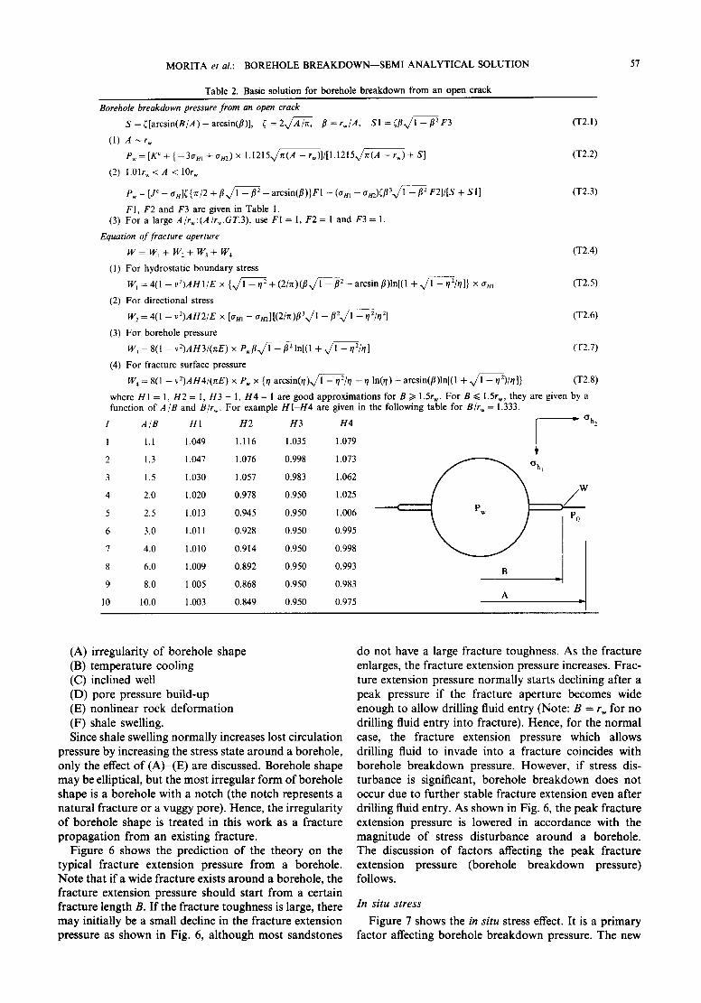
Table 2. Basic solution for borehole breakdown from an open crack
57
Borehole breakdown pressure f rom an open crack
S = ~[arcsin(B/A)-- arcsin(fl)], ~ = 2 Ax~x//A~, fl = r , / A , S1 = ~flx/1 - f12 F3 (T2.1)
(I) A ~ r w
e , = [K c + { -3or m + a m ) x 1.1215 n , , / ~ - rw)l/[l.1215.,/~(A - rw) + S] (T2.2)
(2) 1.01rw < A < 10r,~
Pw = [jc _ an]( {rr/2 + f l x / l - f12 _ arcsin(f l )}r l - (tr m - an2)(fl3x/1 - f12 F2]/[S + SI ] (T2.3)
F1, F2 and F3 are given in Table 1. (3) For a large A/r~:(A/r , . .GT.3) , use F I = 1, F2 = 1 and F3 = 1.
Equation o f fracture aperture
W = W ~ + W 2 + W 3 + W 4 (T2.4)
(1) For hydrostatic boundary stress
W~ = 4(1 - vZ)AH l IE x { l x / f ~ 5 - q 2 + (2 /n ) ( / tx / l - / t 2 - arcsin/t) ln[(l + x/1 - q2/q]} x au~ (T2.5)
(2) For directional stress
W 2 = 4(1 -- v2)AH2/E x [tr m -- am][(2/n)fl31,,/i~i-~2x/l -- q2/q2] (T2.6)
(3) Fo r borehole pressure
W 3 = 8(1 - vZ)AH3/(nE) x P w f l l ~ / ~ 2 - ~ 21n[(l + 1,,/~-q2/rll (T2.7)
(4) For fracture surface pressure W4 = 8(1 -v2)AH4/(nE) x P~ x {r/arcsin(,/)~/1 --t/2/q -r/In(r/)- arcsin(fl)ln[(l + 1 , , / ~ - q2)/*/]} (T2.8)
where H1 = 1, H2 = I, H3 = 1, H4 = 1 are good approximations for B/> 1.5r w. For B ~< 1.5r W, they are given by a function of A/B and B/r,~. For example H I - H 4 are given in the following table for B/rw = 1.333.
I A /B H1 H2 H3 H4 D Oh2
1 1.1 1.049 I. 116 1.035 1.079
2 1.3 1.047 1.076 0.998 1.073
3 1.5 1.030 1.057 0.983 1.062
4 2.0 1.020 0.978 0.950 1.025
5 2.5 1.013 0.945 0.950 1.006
6 3.0 1.011 0.928 0.950 0.995
7 4.0 1.010 0.914 0.950 0.998
8 6.0 1.009 0.892 0.950 0.993
9 8.0 1.005 0.868 0.950 0.983
10 10.0 1.003 0.849 0.950 0.975
ohl j / W
B D PI A
(A) irregularity of borehole shape (B) temperature cooling (C) inclined well (D) pore pressure build-up (E) nonlinear rock deformation (F) shale swelling. Since shale swelling normally increases lost circulation
pressure by increasing the stress state around a borehole, only the effect of (A)-(E) are discussed. Borehole shape may be elliptical, but the most irregular form of borehole shape is a borehole with a notch (the notch represents a natural fracture or a vuggy pore). Hence, the irregularity of borehole shape is treated in this work as a fracture propagation from an existing fracture.
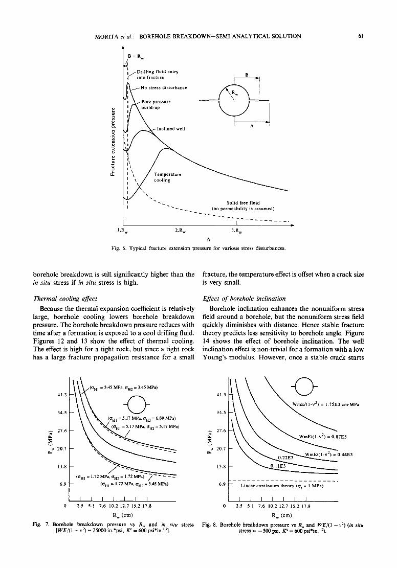
Figure 6 shows the prediction of the theory on the typical fracture extension pressure from a borehole. Note that if a wide fracture exists around a borehole, the fracture extension pressure should start from a certain fracture length B. I f the fracture toughness is large, there may initially be a small decline in the fracture extension pressure as shown in Fig. 6, although most sandstones
do not have a large fracture toughness. As the fracture enlarges, the fracture extension pressure increases. Frac- ture extension pressure normally starts declining after a peak pressure if the fracture aperture becomes wide enough to allow drilling fluid entry (Note: B = rw for no drilling fluid entry into fracture). Hence, for the normal case, the fracture extension pressure which allows drilling fluid to invade into a fracture coincides with borehole breakdown pressure. However, if stress dis- turbance is significant, borehole breakdown does not occur due to further stable fracture extension even after drilling fluid entry. As shown in Fig. 6, the peak fracture extension pressure is lowered in accordance with the magnitude of stress disturbance around a borehole. The discussion of factors affecting the peak fracture extension pressure (borehole breakdown pressure) follows.
In s i tu s t ress
Figure 7 shows the in s i tu stress effect. It is a primary factor affecting borehole breakdown pressure. The new
58 MORITA et al.: BOREHOLE BREAKDOWN--SEMI ANALYTICAL SOLUTION
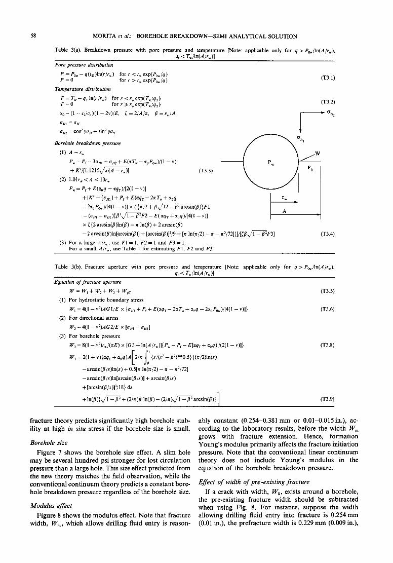
Table 3(a). Breakdown pressure with pore pressure and temperature [Note: applicable only for q >Po~/ln(A/rw), qt < T~/ln(A/r,)]
Pore pressure distribution
P = Po~ - q(tD)ln(r/rw) for r < r~ exp(Pow/q) P = 0 for r > r w exp(Pow/q )
Temperature distribution
T = Tw--qvln(r/r~) for r <rwexp(Tw/qv ) T = 0 for r >1 rwexp(Tw/qv )
%=(1--Ci/Cb)(1--2v) /E, ~,=2/A/r~, f l = r ~ / A
~HI ~ (TH
am = cos 2 yau + sin 2 7av
Borehole breakdown pressure
(1) A ~ r~
P~ - Pr - 3am + am + E(aT~ + %Pow)/(1 -- v)
+ KC/[l .1215x/~ -- r~)]
(2) 1.01rw < A < 10rw
Pw = Pf+ E(%q + ctqr)/[2(l - v)]
+[K ¢ -- {am] + Pf+ E(aqz - 2ct T w + aoq
(T3.3)
-2aoPo~)/[4(l - v)] x ~{n/2 + fix/12 - fl: arcsin(fl)}F1 [
-- (am -- am)(fl3~/1 -- f12F2 - E( ~qT + ~0q)/[4( 1 -- v)]
x ({2 arcsin(fl)ln(fl) - 7r ln(fl) + 2 arcsin(fl)
--2 arcsin(fl)ln[arcsin(fl)] + [arcsin(fl)]3/9 + [n ln(n/2) - ~ - n 3/72]}]/[~flx/1 - f12F3]
(3) For a large A/rw, use F1 = 1, F 2 = 1 and F3 = 1. For a small A/r w, use Table 1 for estimating F1, F2 and F3.
(T3.1)
(T3.2)
I~ ~h2
(~hl
I rw
A
(T3.4)
Table 3(b). Fracture aperture with pore pressure and temperature [Note: applicable only for q >Pow/ln(A/rw), qt < Tw/ln(A/rw)]
Equation o f fracture aperture
w = w, + w2 + w~ + w :
(1) For hydrostatic boundary stress
W l = 4(1 -- v 2)A G 1/E × { a m + Pf + E(~tqT -- 2ct T w + % q -- 2% P0~)/[4( I -- v )] }
(2) For directional stress
W 2 = 4(1 - v2)AG2/E × [am - am]
(3) For borehole pressure
W3 = 8(1 - v2)r,/(uE) x [G3 + ln(A/rw)]{P w - P f - E[ctq x + %q)/(2(1 - v)]}
= 2(1 + V) (~qT q- %q)Al2/n" --t. 1 {s/(s 2 -- fl')**0.5} {(n/2)ln(s) WT
-- arcsin(fl/s)ln(s) + 0.5[n ln(u/2) -- u -- n 3/72]
-- arcsin(fl/s )ln[arcsin(fl/s)] + arcsin(fl/s)
+ [arcsin(fl/s)]~/18} ds
+ l n ( f l ) { , / 1 - f12 + (2/ ,0fl ln(fl) - ( 2 / . ) l ~ / V S ~ - ~: arcsin(fl)}[ /
(T3.5)
(T3.6)
(T3.8)
(T3.9)
f r ac tu re t h e o r y p red ic t s s igni f icant ly h igh b o r e h o l e s tab-
il i ty a t h igh in s i tu stress i f the b o r e h o l e size is small .
B o r e h o l e s i ze
F i g u r e 7 shows the b o r e h o l e size effect. A s l im ho le
m a y be severa l h u n d r e d psi s t r o n g e r fo r lost c i r cu l a t i on
p r e s su re t h a n a la rge hole . Th i s size effect p r e d i c t e d f r o m
the n e w t h e o r y m a t c h e s the field o b s e r v a t i o n , whi le the
c o n v e n t i o n a l c o n t i n u u m t h e o r y pred ic t s a c o n s t a n t bo re - h o l e b r e a k d o w n p ressu re regard less o f the b o r e h o l e size.
M o d u l u s e f f ec t
F i g u r e 8 shows the m o d u l u s effect. N o t e tha t f r ac tu re w id th , Wm, wh ich a l lows dr i l l ing f luid en t ry is r ea son -
ab ly c o n s t a n t (0 .254-0 .381 m m o r 0 . 0 1 - 0 . 0 1 5 i n . ) , ac-
c o r d i n g to the l a b o r a t o r y resul ts , be fo re the w i d t h Wm
g rows wi th f r ac tu re ex tens ion . H e n c e , f o r m a t i o n Y o u n g ' s m o d u l u s p r i m a r i l y affects the f r ac tu re in i t i a t ion
pressure . N o t e tha t the c o n v e n t i o n a l l inear c o n t i n u u m
t h e o r y does n o t inc lude Y o u n g ' s m o d u l u s in the
e q u a t i o n o f the b o r e h o l e b r e a k d o w n pressure .
E f f e c t o f w i d t h o f p r e - e x i s t i n g f r a c t u r e
I f a c r ack wi th wid th , W0, exists a r o u n d a b o r e h o l e , the p re -ex i s t ing f r ac tu re w id th s h o u l d be sub t r ac t ed w h e n us ing Fig. 8. F o r ins tance , suppose the w id th a l l owing dr i l l ing f luid en t ry in to f r ac tu re is 0.254 m m (0.01 in.), the p r e f r ac tu r e w id th is 0.229 m m (0.009 in.),
M O R I T A et al.: B O R E H O L E B R E A K D O W N - - S E M I A N A L Y T I C A L S O L U T I O N 59
and E l ( 1 - v 2) = 6890 MPa (1.E6 psi), then a curve for W m E / ( 1 - v 2) = (0.254-0.229) x 6890 = 172 mm- MPa or (0.01 - 0 . 0 0 9 ) × 1. E6 = 1. E3 in.psi should be used. The result shows that preexisting fracture width is an important factor for breakdown pressure. The deri- vation of P~ - A / R w - W relation for a borehole with a pre-existing crack is shown in the Appendix, Section A.3.
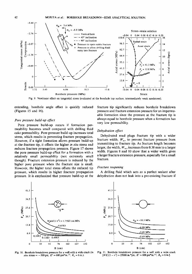
Nonlinear deformation of rock
There are three non-linear deformations often ob- served for sedimentary rocks. They are Mode I nonlin-
earity (crack closure or Mode I microcrack growth), shear type plasticity, and plasticity due to pore volume crushing. The Mode I nonlinearity has a similar effect as macrocrack growth, hence, it can be treated approxi- mately as a part of a macrocrack growth problem. Plastic nonlinearity occurs if a rock is soft relative to in
s i tu stress. Figure 9 shows the effect o f plasticity for a relatively weak rock (the stress-strain relation is given in the figure). The tangential stress may become compres- sive due to plasticity if borehole pressure is too high. For some stress combinations, tangential stress remains
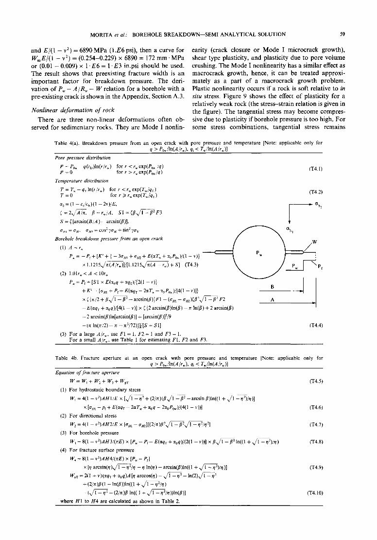
T a b l e 4(a) . B r e a k d o w n p r e s s u r e f r o m a n o p e n c r a c k w i t h p o r e p r e s s u r e and temperature [Note: a p p l i c a b l e o n l y for q > Po~/ln(A/rw), qt < Tw/ln(A/r~)]
Pore pressure distribution
e = Po~ - q(tt))ln(r/rw) for r < r w e x p ( P 0 ~ / q ) P = 0 for r > r~ exp(Pow/q)
Temperature distribution
T = T~- -qT ln ( r / rw) for r <rwexp(Tw/qx ) T = 0 for r >1 r~ exp(T~/qT )
~0 = (1 -- Ci/Cb)(1 -- 2v)/E,
( = 2 Ax/A~, f l=r ,~ /A , S I = ~ / / lxfi~---//2F3
S = ~ [ a r c s i n ( B / A ) - arcs in( / / ) ] ,
Borehole breakdown pressure f rom an open crack
(T4.1)
(T4.2)
D ~h2
P ~ = - - P f + [ K C + { - - 3 t r m + t r m + E ( ~ T w + % P o w ) / ( 1 -- v)} ( ~ "i
× l . 1 2 1 5 x ~ ( A ~ w ) ] / [ 1 . 1 2 1 5 x / ~ - r , . ) + S ] (T4.3) w I ~ P f
(2) 1.01rw < A < 10r w
P~ = Pf + [S1 × E ( % q + ctq-r)/{2(1 - v)} _ -
+ K c - {tr,u I + Pf + E(etqx - 2ctT, + % P 0 , ) / [ 4 ( 1 - v)]} B
× ~" { ~ / 2 + f l ~ - - - - / / 2 _ a r c s i n ( f l ) } r l - (tr m - a m)~f l31x f~- - f l2r2
--E(ctqx + % q ) / [ 4 ( I -- v)] × ~{2 a rc s in ( f l ) ln ( f l ) -- ~ In( / / ) + 2 a rcs in ( / / ) - I
- -2 a rcs in ( / / ) ln [a rcs in ( / / ) ] + [arcs in(f l )]3/9
+ ( ~ l n0z /2 ) -- r~ -- n3/72)}]/[S + S1] (T4.4)
(3) F o r a l a r g e A/rw, use F I = 1, F 2 = 1 a n d F 3 = 1. F o r a s m a l l A/rw, use T a b l e 1 for e s t i m a t i n g F I , F 2 a n d F3 .
T a b l e 4b. F r a c t u r e a p e r t u r e a t an o p e n c r a c k w i t h p o r e p r e s s u r e and temperature [Note: a p p l i c a b l e o n l y for q > Pow/ln(A/rw), q, < Tw/ln(A/rw)]
Equation o f f racture aperture
W = w, + w2 + W3 + wpT (1) F o r h y d r o s t a t i c b o u n d a r y stress
W~ = 4(1 - v2)AH 1/E × [x/1 - r/2 + ( 2 / n ) ( B x / l - f12 _ a r c s in f l) ln((1 + x / 1 - r/2)/r/)]
× [o m + pf + E(CtqT -- 2ct T w + % q -- 2% P0w)/(4( 1 - v ))]
(2) F o r directional stress
W 2 = 4(I -- vZ)AH2/E × [tr m -- trml[(2/n)fl31~--fl2--fl2x/1 -- rl2/q2 l
(3) F o r b o r e h o l e p r e s s u r e
W 3 = 8(1 - v2)AH3/(rcE) × [Pw - P f - E(~tqT + % q ) / ( 2 ( 1 -- v))] × f l x / l -- f12 l n ( ( l + x /1 -- tl2)/q)
(4) F o r f r a c t u r e s u r f ace p r e s s u r e
W4 = 8(1 - v2)AH4/ (nE) x [Pw - Pr]
× [ r / a r c s i n ( r / ) x / 1 - ~/2/r/ - r / l n ( q ) - a rcs in ( / / ) ln ( (1 + x /1 - r/2)#/)]
W~T = 2(1 + v)(~qz + % q ) A lr / a rccos( r / ) - - w / 1 - , 2 _ l n ( 2 ) x / ~ _ r/z
+ ( 2 / n ) / / ( 1 - ln(f l ) ) ln((1 + x / 1 - q2/q)
_ ( x / l _ n2 _ ( Z / n ) / / I n ( ( 1 + x / 1 - n2/n)) ln( / / ) ]
where H 1 to H 4 a re c a l c u l a t e d as shown in T a b l e 2.
(T4.5)
(T4.6)
(T4.7)
(T4.8)
(T4.9)
(T4.10)
60 MORITA et al.: BOREHOLE B R E A K D O W N - - S E M I ANALYTICAL SOLUTION
eL
eL
o %
g-, > I
55.1
48.2
41.3
34.5
27.6
20.7
13.8
6.9
0
0.875
1.750
2.625
/ / / - " / . . "
K c -- 59 MPa.cm It2 . - / . ' / / / ' " ~ J
/ . " / ' "
_
/ ' . / Ko-- 3 0 ~ , " / / ~ o
- " " / / / 59 ~ - I " ~.- _ ,,-:,, _/~ _...~--- ...i.--
p- ..::...:~ ._._..----_.7.2.-"'-o"- "/ ..~ • -'" "......-- • "" 2.~ .. .'2.'2"-''
59
~ - - - - 3 - _ __1.4 5 6 7 8 0 9 to
\ . " x , ~ " ~ ~ ~ - , . . . . -5~ . . . . . . . -. \ ~ "~, " ~ .
_ \ . k"-~, , ,~ - - . , -
.,,'..,\~ ~.., -..,, -. \ N . ~ ~ "~59 "-.~
. . . . 59 ".. " . , \ \ \ "'-. "x.
_ ", ~ , . \ \ \ 0 - - . , , - - . ",..,,. \\'~.3o ~.\
\\\ -,,
pa~)" "\ N\ 59~~ X
~ ' ~ " (~ - I ~ P O/./2= 1.72MPa) "~, "'.. " ~ ' ~ .
(OH1 = 0 MPa, ott 2 = 0 MPa) N. \
Fig. 5. Effect of in s i tu relation on P~ - A / R w - - W relation (R~ = 6 in.).
compressive without opening a fracture. Such plastic effects increase borehole breakdown pressure.
Table 5 summarizes the well pressure inducing fluid invasion into the fracture. A failure limit is imposed to plastic strain to those cases where tangential stress never becomes tension, assuming nonuniform deformation destabilizes the borehole if plastic strain exceeds a certain value. The table compares the nonlinear fracture theory with the conventional linear elasticity theory. The
nonlinear theory consistently predicts a higher fluid invasion pressure into the fracture.
Irregular borehole shape The most serious form of irregular borehole shape is
a wide crack around a borehole. Figures 10 and 11 show the effect of a wide crack upon breakdown pressure. The borehole breakdown pressure is significantly reduced by wide cracks, but even with a relatively large crack,
Table 5. Wellbore pressure inducing fluid invasion into fracture 5(a) Rock type: weak (unconfined com-
pressive strength = 150psi)
(O'H~ GV) ( - 0 . 05 kpsi, - I kpsi) Linear Nonlinear
continuum fracture (psi) (psi)
Well angle 0 ° 1000 1060
90 ° 500 630
5(b) Rock type: intermediately weak (unconfined compressive strengths = 1 kpsi)
( - 0 . 5 kpsi, - 1 kpsi) ( - 0 . 5 kpsi, - 2 kpsi) ( - 1 kpsi, - 2 kpsi) Linear Nonlinear Linear Nonlinear Linear Nonlinear
continuum fracture continuum fracture continuum fracture (psi) (psi) (psi) (psi) (psi) (psi)
Well angle 0 ° I000 1600 1000 1900 2000 2820
45 ° 750 1230 90 ° 500 840 - 500 500 1000 1650
M O R I T A et al.: B O R E H O L E B R E A K D O W N - - S E M I A N A L Y T I C A L S O L U T I O N
~ B = R w
II Drilling fluid entry / into fracture B
~ No stress disturbance ~ [
I I \ . / P o r e pressure ~
~ I ~ lid-up
¢0
\
I ~ ~ ~ Solid free fluid I ~ ~ ~ ~ ~ ~ ~ (no permeability is assumed)
1 ,R w 2,R w 3,R w
A
Fig. 6. Typica l fracture extension pressure for various stress disturbances.
61
borehole breakdown is still significantly higher than the in situ stress if in situ stress is high.
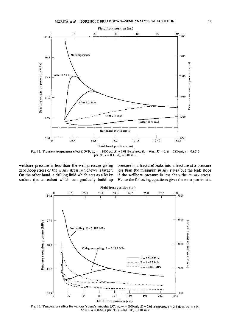
Thermal cooling effect Because the thermal expansion coefficient is relatively
large, borehole cooling lowers borehole breakdown pressure. The borehole breakdown pressure reduces with time after a formation is exposed to a cool drilling fluid. Figures 12 and 13 show the effect of thermal cooling. The effect is high for a tight rock, but since a tight rock has a large fracture propagation resistance for a small
fracture, the temperature effect is offset when a crack size is very small.
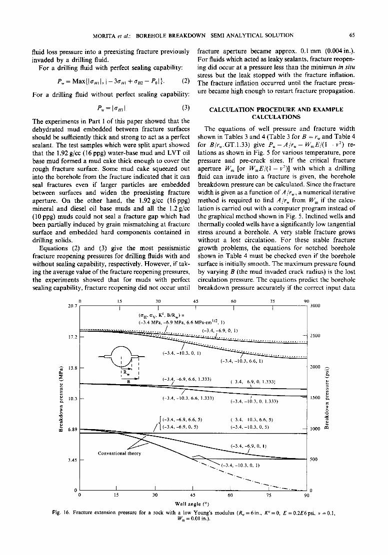
Effect of borehole inclination
Borehole inclination enhances the nonuniform stress field around a borehole, but the nonuniform stress field quickly diminishes with distance. Hence stable fracture theory predicts less sensitivity to borehole angle. Figure 14 shows the effect of borehole inclination. The well inclination effect is non-trivial for a formation with a low Young's modulus. However, once a stable crack starts
Fig.
4
34.5 \ \ " ~ (OHI=5"17MPa'OH2 =6'89MPa)
\ k ~ ( O H I = 5 . 1 7 M P a , OH2=5.17MPa)
e 21).7
1 3. 8
(°ttl 1 7 2 M P a ~
6.9 - (oN! = 1.72 MPa, olt 2 = 3.45 MPa)
I I I I I I I 0 2.5 5.1 7.6 10.2 12.7 15.2 17.8
R w (cm)
7. Borehole breakdown pressure vs Rw and in situ stress [ W E / ( l - v 2) = 25000 in.*psi, K c = 600 psi*in J/2].
41.3
34.5
27.6
e 217.7
13.8
6.9
~ 2 3 cm.MPa
7E3
.44E3
Linear continuum theory (o t = 1 MPa)
I I I [ I I I 0 2.5 5.1 7.6 10.2 12.7 15.2 17.8
R w (cm)
Fig. 8. Borehole breakdown pressure vs Rw and WE~(1 - v 2) (in situ stress -- - 5 0 0 psi, K c = 600 psi*inJa) .
62
-3.44
-2.76
,~ ~-2.07
-1.38-
= -0.69 -- t~
MORITA et al.: BOREHOLE BREAKDOWN--SEMI ANALYTICAL SOLUTION
0 m
o = 0.69 1.72
m t~ H = -3.4 MPa
-- \ '\" q°v=-6'9--'--~MPa ' -0.04 Str~.s~4st0r.~i8n0r.;12ti0°16 0.20
\ ~ ~ ~ i5s~i!!!!!!! ! 110.0 ~ i i [ [ 16
- oo i table fracture 96.5 ~- ~Radial strain f x
' \ ~ ~ entry into f r a c t u r e T / " ! 8628
XXXx\ "'\'\. ~ / " ~ l • Pc = 41.3 MPa \\ \ "\. ~ / 7" / .~ 41.3 [ - - / Pc=13.SMPa _ 6
" \ \ O i . _ . x \ . \ t . . . _ _ . ~ J "< 27"6 ~ ~ :g~ -- 4
13.8 ~-- ~ -- 2 I ~Pc =0
I I I I 0 I ~ t I I L 0 3.45 6.89 10.3 13.8 -0.04 0 0.04 0.08 0.12 0.16 0.20
Borehole pressure (MPa) Strain
Fig. 9. Nonlinear effect on tangential stress (evaluated at the borehole top surface, intermediately weak sandstone).
<
extending, borehole angle effect is quickly reduced (Figures 15 and 16).
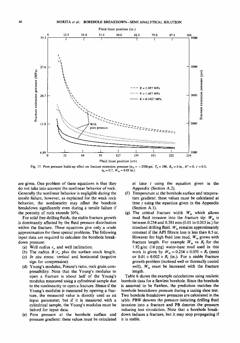
Pore pressure build-up effect Pore pressure build-up occurs if formation per-
meability becomes small compared with drilling fluid cake permeability. Pore pressure build-up increases total stress, which results in preventing fracture propagation. However, if a tight formation allows pressure build-up at the fracture tip, it offsets the higher in situ stress and reduces fracture propagation pressure. Figure 17 shows the pore pressure build-up effect for a formation with a relatively small permeability (not extremely small though). Fracture extension pressure is reduced by the higher pore pressure when the fracture size is small. However, the higher total stress offsets the reduced tip pressure, which results in higher fracture propagation pressure. It is emphasized that pressure build-up at the
fracture tip significantly reduces borehole breakdown pressure and fracture extension pressure for an imperme- able formation since the pressure at the fracture tip is always equal to borehole pressure when a formation has very low permeability.
Dehydration effect Dehydrated mud plugs fracture tip with a wider
fracture width, Win, to prevent fracture pressure from transmitting to fracture tip. As fracture length becomes larger, the width, Wm, increases from 0.38 mm to a larger width. Figures 8 and 10 show that a wider width gives a larger fracture extension pressure, especially for a small fracture.
Fracture reopening
A drilling fluid which acts as a perfect sealant after dehydration does not leak into a pre-existing fracture if
41.3
34.5
27.6 ~
~ 20.7
13.8
6.9 0 22E3 ~ ,' 0.11E3 0.44E3
I I I I I I 0 25 51 76 102 127 152
B (cm) Fig. 10. Borehole breakdown pressure for a well with a wide crack (in
situ stress = - 500 psi, K ¢ = 600 psi*in.~/2, Rw = 6 in.).
41.3
34.5
27.6
~,~ 20.7
13.8 ~ MPa
-3.45 MPa 6.9 -0.69 MPa
L I I I I I 0 25 51 76 102 127 152
B (cm) Fig. 1 I. Borehole breakdown pressure for a well with a wide crack
[WE~(1 - v 2) = 25000 in.*psi, K c = 600 psi*in, t/2, R W = 6 in.].
eL
--t
e~
O
o~
0 19.3
16.5
13.8
11.0
8.27
5.51
MORITA et al.: BOREHOLE BREAKDOWN--SEMI ANALYTICAL SOLUTION
Fluid front position (in.)
10 20 30 40 50 60 I I I [ I
-After 0 ~ t e m p e r a t u r e
.---'- -----"
. ~ . ~-" " ~ After 2.3 days
2800
--'"" " " - After 11.6 days
Horizontal in situ stress
I I [ 25.4 50.8 76.2 101.6
Fluid front position (cm)
2400
2000
O
1600 ~
1200
I 800 127.0 152.4
Fig. 12. T r a n s i e n t t e m p e r a t u r e effect (100°F , an = - 1000 psi , K t = 0 .0116 cm2/sec , R w = 6 in., K c = 0, E = 2 E 6 psi, • = 0 . 8 E - 5 pe r OF, v = 0 . 1 , W m = 0 . 0 1 in.).
63
wel lbore pressure is less t h a n the well pressure g iv ing zero h o o p stress or the in situ stress, whichever is larger. O n the o the r h a n d , a dr i l l ing fluid which acts as a leaky sea lan t (i.e. a sea lan t which can g radua l ly bu i ld up
pressure in a f racture) leaks in to a f rac ture at a pressure less t h a n the m i n i m u m in situ stress b u t the leak s tops if the wel lbore pressure is less t h a n the in situ stress. Hence the fo l lowing e q u a t i o n s gives the mos t pessimist ic
27.6 -- eL
.~ 20.7
9
~ 13.8
Fluid front position (in.)
0 12.5 25.0 37.5 50.0 62.5 75.0 87.5 100 34.5 5000 I I I I I [ I
oling, E = 5.5E7 MPa
~ 50 degree cooling, E = 5.5E7 MPa
".. " ~ . . . . . . . . . E = 1.4E7 MPa " , . / ~ . . . . . E=O.34E7MPa
" - ~ 2 -.7._ : . : _ __ . . . . . . . . . . . . . . . . . . . . . . . . .
-- 4000
-- 3000 .~
2000
1000 254
6 . 8 9 [ I I I I [ I 0 32 64 95 127 159 191 222
Fluid front position (cm)
Fig. 13. Temperature effect for various Young's modulus (50 °, gn = - I000 psi, K, = 0.0116 cm:/sec, t = 2.3 days, Rw = 6 in. Kc=O, • = 0.8E-5 per °F, v =0.1, Wm= 0.01 in.).
6 4
0 82.7
68.9
55.1 gh
~ 41.3
o
m 27.6
13.8
M O R I T A et al.: BOREHOLE B R E A K D O W N - - S E M I A N A L Y T I C A L SOLUTION
15 30 45 60 75
WmE/(l-v 2) = 1.75 x 103 cm.MPa
1.31 x 10³ / ~
I I
8.75 x 1 0 2 / ~
_ 4.38 x 10²
: : : : : : : : : : : : : ~ i i ~ : ~ ' ~ 2 ~ - . ) : ! ! . x l O 2 / 8 . 7 5 x l O
. . . . . . . . . . . . . . . . . . . . . . . . . . . . . . . . .
........... ::::::::::::::::::::::::::::::::::::::::::::--- "-------___________
I I I I 25.4 50.8 76.2 101.6
Well angle (o)
90 12
- - 1 0
8
- - 2
I 0 127.0 152.4
g "
.'Z'.
.o
..s
.o e~
O "O
o O .o o m
Fig. 14. Elastic modulus effect on borehole breakdown pressure (a n = - 2 5 0 0 p s i , a, = - 5 0 0 0 p s i , Rw= 6in., B/Rw = 1, K ~ = 0).
8.27
7.58
~" 6.89 eL
6.20 .o ca,
5.51
.o
~ 4.82
4.13
Fluid front posi t ion (in.)
0 I0 20 30 40 50 60 70 80
I I I I I I I
\
O H = - .4MPa
o v = -6.9 MPa
t l = ~ l F r o m t o p a = 0, 15, 30, 45, 60, 75 and 90 degree
90 100 I 1200
- - 1100
- 1 0 0 0
e~
- 9 o o ~
- 800
- 700 ~
-I! 600
500 254
3.45 1 I t I I I I I I 0 25.4 50.8 76.2 101.6 127.0 152.4 178 203 229
Fluid front posi t ion (cm)
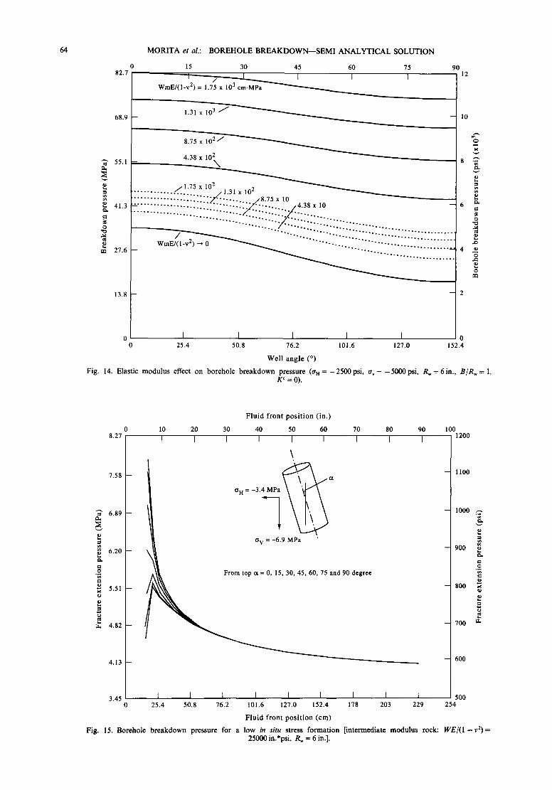
Fig. 15. Borehole breakdown pressure for a low in situ stress formation [intermediate modulus rock: W E / ( I - v 2 ) = 25000 in.*psi, Rw = 6 in.].
M O R I T A et al.: BOREHOLE B R E A K D O W N - - S E M I A N A L Y T I C A L SOLUTION 65
fluid loss pressure into a preexisting fracture previously invaded by a drilling fluid.
For a drilling fluid with perfect sealing capability:
Pw = Max{I trm l, I - 30"HI + 0"/'/2 - - e0l}. (2)
For a drilling fluid without perfect sealing capability:
Pw = I Onl ] (3)
The experiments in Part I of this paper showed that the dehydrated mud embedded between fracture surfaces should be sufficiently thick and strong to act as a perfect sealant. The test samples which were split apart showed that the 1.92 g/cc (16 ppg) water-base mud and LVT oil base mud formed a mud cake thick enough to cover the rough fracture surface. Some mud cake squeezed out into the borehole from the fracture indicated that it can seal fractures even if larger particles are embedded between surfaces and widen the preexisting fracture aperture. On the other hand, the 1.92g/cc (16ppg) mineral and diesel oil base muds and all the 1.2 g/cc (10 ppg) muds could not seal a fracture gap which had been partially induced by grain mismatching at fracture surface and embedded hard components contained in drilling solids.
Equations (2) and (3) give the most pessismistic fracture reopening pressures for drilling fluids with and without sealing capability, respectively. However, if tak- ing the average value of the fracture reopening pressures, the experiments showed that for muds with perfect sealing capability, fracture reopening did not occur until
fracture aperture became approx. 0.1 mm (0.004in.). For fluids which acted as leaky sealants, fracture reopen- ing did occur at a pressure less than the minimun in situ stress but the leak stopped with the fracture inflation. The fracture inflation occurred until the fracture press- ure became high enough to restart fracture propagation.
CALCULATION PROCEDURE AND EXAMPLE CALCULATIONS
The equations of well pressure and fracture width shown in Tables 3 and 4 (Table 3 for B = r~ and Table 4 for B/rw.GT.1.33) give P ~ - A / r w - W m E / ( I - v 2) re- lations as shown in Fig. 5 for various temperature, pore pressure and pre-crack sizes. If the critical fracture aperture Wm [or WmE/( I - v2)] with which a drilling fluid can invade into a fracture is given, the borehole breakdown pressure can be calculated. Since the fracture width is given as a function ofA/rw, a numerical iterative method is required to find A/rw from Wm if the calcu- lation is carried out with a computer program instead of the graphical method shown in Fig. 5. Inclined wells and thermally cooled wells have a significantly low tangential stress around a borehole. A very stable fracture grows without a lost circulation. For these stable fracture growth problems, the equations for notched borehole shown in Table 4 must be checked even if the borehole surface is initially smooth. The maximum pressure found by varying B (the mud invaded crack radius) is the lost circulation pressure. The equations predict the borehole breakdown pressure accurately if the correct input data
o
o
g t . ,
0 15 30 45 60 75 90 20.7 I I I I [
(O H, O V, K c, B/Rw) = (-3.4 MPa, -6.9 MPa, 6.6 MPa.cm I/2, 1)
. . . . . . . . . . . . . . . . . . . . -1 . . . . . . . . . . . . . / (-3.4, -6.9, O, 1) 17.2 -- " . . . . . . " ' " ' ~ ~ . . . . . . . . . . . . . . .
4 / " ' ' ' " " ' " ' ' " " ' ' ' " " ' " . . . . . . . . . . . . . . .
(-3.4, -10.3, 6.6, 1)
13 .8 - - ~ - - ~ I --
10.3
6.89
I R w I i I,LI (-3.4, -6.9, 6.6, 1.333) / (-3.4, -6.9, 0, 1.333)
(-3.4, -10.3, 6.6, 1.333) t (-3.4, -10.3, 0, 1.333)
.~ (-3.4, -6.9, 6.6, 5) (-3.4, -10.3, 6.6, 5)
/ l (-3.4, -6.9, 0, 5) (-3.4, -10.3, 0, 5)
3000
2500
-- 1500
-- 1000
500
2000
m
Q
g
~ ~ (-3.4, -6.9, 0, 1) /
Conventional theory ,, " " ' ~ 3.45
~ " ~ . ~ " " ( " 3 4 -10.3, 0, 1) • . - . ,
0 I I I I I " " ~ - ~ . . 0 0 15 30 45 60 75 90
Well angle (°)
Fig. 16. Fracture extension pressure for a rock with a low Young's modulus (Rw = 6in., K c = 0, E = 0.2E6 psi, v = 0.1, Wm= 0.01 in.).
66
o ga.
O
o
O .o
0 34.5
27.6 --
20.7 --
13.8 --
6 .89
M O R I T A e t al.: B O R E H O L E B R E A K D O W N - - S E M I A N A L Y T I C A L S O L U T I O N
F l u i d f r o n t p o s i t i o n ( i n . )
12.5 25.0 37.5 50.0 62.5 75.0
I I 1 [ I I
X~, - - - E = 5 . 5 E 7 M P a
XX . . . . . . E = 1.4E7 MPa \ \
\ x E = 0 .34E7 MPa
~ ~ . ~ _ . : pore pressure - - - ~ . ~ - _ _ . . . . . . . . . . . . . . . - - - - - - - - - - - - - -
87.5 100 I 5000
4000
3000
2000
.o
tL
I I I I I I I 1ooo 32 64 95 127 159 191 222 254
F l u i d f r o n t p o s i t i o n ( c m )
Fig. 17. P o r e p r e s s u r e b u i l d - u p effect o n f r a c t u r e e x t e n s i o n p r e s s u r e ( a n = - 2 5 0 0 psi, Td = I00 , Rw = 6 in. , K c = 0, v = 0.1, % = 0.7, Wm = 0.01 in.).
are given. One problem of these equations is that they do not take into account the nonlinear behavior of rock. Generally the nonlinear behavior is negligible during the tensile failure, however, as explained for the weak rock behavior, the nonlinearity may affect the borehole breakdown significantly even during a tensile failure if the porosity of rock exceeds 30%.
For solid free drilling fluids, the stable fracture growth is dominantly affected by the fluid pressure distribution within the fracture. These equations give only a crude approximation for these special problems. The following input data are required to calculate the borehole break- down pressure:
(a) Well radius rw and well inclination. (b) The radius B:rw plus the surface crack length. (c) In situ stress: vertical and horizontal (negative
sign for compression). (d) Young's modulus, Poison's ratio, rock grain com-
pressibility: Note that the Young's modulus to open a fracture is about half of the Young's modulus measured using a cylindrical sample due to the nonlinearity to open a fracture. Hence if the Young's modulus is measured by opening a frac- ture, the measured value is directly used as an input parameter; but if it is measured with a cylindrical sample, the Young's modulus must be halved for input data.
(e) Pore pressure at the borehole surface and pressure gradient: these values must be calculated
at time t using the equation given in the Appendix (Section A.2).
(f) Temperature at the borehole surface and tempera- ture gradient: these values must be calculated at time t using the equation given in the Appendix (Section A. 1).
(g) The critical fracture width Wm which allows mud fluid invasion into the fracture tip: Wm is between 0.254 and 0.381 mm (0.01 to 0.015 in.) for standard drilling fluid. Wm remains approximately constant if the API filtrate loss is less than 0.5 co. However for high fluid loss mud, Wm grows with fracture length. For example Wm vs Rr for the 1.92g/cc (16ppg) water-base mud used in this work is given by Wm= 0.254 + 0.051 X Rr (mm) or 0.01 + 0.002 x Rf (in.). For a stable fracture growth problem (inclined well or thermally cooled well), Wm must be increased with the fracture length.
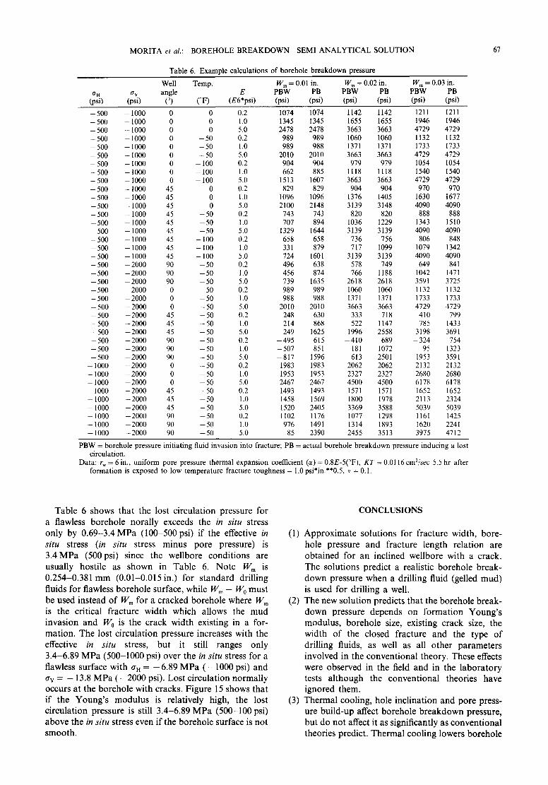
Table 6 shows the example calculations using realistic borehole data for a flawless borehole. Since the borehole is assumed to be flawless, the prediction matches the borehole breakdown pressure during a casing shoe test. Two borehole breakdown pressures are calculated in the table. PBW denotes the pressure initiating drilling fluid invasion into a fracture and PB denotes the pressure inducing lost circulation. Note that a borehole break- down induces a fracture, but it may stop propagating if it is stable.
M O R I T A et al.: B O R E H O L E B R E A K D O W N - - S E M I A N A L Y T I C A L S O L U T I O N
Table 6. Example calculat ions o f borehole brea kdo wn pressure
67
Well Temp. Wm = 0.01 in. W m = 0.02 in. W m = 0.03 in. or. a v angle E P B W PB P B W PB P B W PB
(psi) (psi) (°) (°F) (E6*psi) (psi) (psi) (psi) (psi) (psi) (psi)
- 500 - 1000 0 0 0.2 1074 1074 1142 1142 1211 1211 - 500 - 1000 0 0 1.0 1345 1345 1655 1655 1946 1946 - 500 - 1 0 0 0 0 0 5.0 2478 2478 3663 3663 4729 4729 - 500 - 1000 0 - 50 0.2 989 989 1060 1060 1132 1132 - 500 - 1000 0 - 5 0 1.0 989 988 1371 1371 1733 1733 - 5 0 0 - 1000 0 - 5 0 5.0 2010 2010 3663 3663 4729 4729 - 500 - 1000 0 - 100 0.2 904 904 979 979 1054 1054 - 500 - 1000 0 - 100 1.0 662 885 1118 1118 1540 1540 - 5 0 0 - 1000 0 - 1 0 0 5.0 1513 1607 3663 3663 4729 4729 - 500 - 1000 45 0 0.2 829 829 904 904 970 970 - 500 - 1000 45 0 1.0 1096 1096 1376 1405 1630 1677 - 500 - 1 0 0 0 45 0 5.0 2100 2148 3139 3148 4090 4090 - 500 - 1 0 0 0 45 - 50 0.2 743 743 820 820 888 888 - 500 - 1000 45 - 5 0 1.0 707 894 1036 1229 1343 1510 - 5 0 0 - 1000 45 - 5 0 5.0 1329 1644 3139 3139 4090 4090 - 500 - 1000 45 - 100 0.2 658 658 736 756 806 848 - 5 0 0 - 1 0 0 0 45 - 100 1.0 331 879 717 1099 1079 1342 - 500 - 1000 45 - 100 5.0 724 1601 3139 3139 4090 4090 - 5 0 0 - 2 0 0 0 90 - 5 0 0.2 496 638 578 749 649 841 - 5 0 0 - 2 0 0 0 90 - 5 0 1.0 456 874 766 1188 1042 1471 - 5 0 0 - 2 0 0 0 90 - 5 0 5.0 739 1635 2618 2618 3591 3725 - 5 0 0 - 2 0 0 0 0 50 0.2 989 989 1060 1060 1132 1132 - 5 0 0 - 2 0 0 0 0 - 50 1.0 988 988 1371 1371 1733 1733 - 5 0 0 - 2 0 0 0 0 - 50 5.0 2010 2010 3663 3663 4729 4729 - 500 - 2 0 0 0 45 - 50 0.2 248 630 333 718 410 799 - 5 0 0 - 2 0 0 0 45 - 5 0 1.0 214 868 522 1147 785 1433 - 5 0 0 - 2 0 0 0 45 - 50 5.0 249 1625 1996 2558 3198 3691 - 500 - 2 0 0 0 90 - 50 0.2 - 4 9 5 615 - 4 1 0 689 - 324 754 - 5 0 0 - 2 0 0 0 90 - 50 1.0 - 5 0 7 851 - 181 1072 95 1323 - 5 0 0 - 2 0 0 0 90 - 50 5.0 - 8 1 7 1596 613 2501 1953 3591
- 1000 - 2 0 0 0 0 - 5 0 0.2 1983 1983 2062 2062 2132 2132 - 1000 - 2 0 0 0 0 - 5 0 1.0 1953 1953 2327 2327 2680 2680 - 1000 - 2 0 0 0 0 - 5 0 5.0 2467 2467 4500 4500 6178 6178 - 1000 - 2000 45 - 5 0 0.2 1493 1493 1571 1571 1652 1652 - 1000 - 2 0 0 0 45 - 50 1.0 1458 1569 1800 1978 2113 2324 - 1000 - 2 0 0 0 45 - 50 5.0 1520 2405 3369 3588 5039 5039 - 1000 - 2 0 0 0 90 - 50 0.2 1102 1176 1077 1298 1161 1425 - 1000 - 2 0 0 0 90 - 5 0 1.0 976 1491 1314 1893 1620 2241 - 1000 - 2 0 0 0 90 - 5 0 5.0 85 2390 2455 3513 3975 4712
P B W = borehole pressure initiating fluid invasion into fracture; PB = actual borehole brea kdo wn pressure inducing a lost circulation.
Data: r w = 6 in., uniform pore pressure thermal expansion coefficient ( ~ ) = 0 .8E-5(°F) , K T = 0 .0116 cm2/sec 5.5 hr after format ion is exposed to l ow temperature fracture toughness = 1.0 psi*in.**0.5, v = 0.1.
Table 6 shows that the lost circulation pressure for a flawless borehole norally exceeds the in situ stress only by 0.69-3.4 MPa (100-500 psi) if the effective in situ stress (in situ stress minus pore pressure) is 3 .4MPa (500psi) since the wellbore conditions are usually hostile as shown in Table 6. Note Wm is 0.254--0.381 mm (0.01-0.015in.) for standard drilling fluids for flawless borehole surface, while Wm- W0 must be used instead of Wm for a cracked borehole where Wm is the critical fracture width which allows the mud invasion and W 0 is the crack width existing in a for- mation. The lost circulation pressure increases with the effective in situ stress, but it still ranges only 3.4-6.89 MPa (500-1000 psi) over the in situ stress for a flawless surface with aH = - 6 . 8 9 MPa ( - 1 0 0 0 psi) and av = - 13.8 MPa ( - 2 0 0 0 psi). Lost circulation normally occurs at the borehole with cracks. Figure 15 shows that if the Young's modulus is relatively high, the lost circulation pressure is still 3.4-6.89 MPa (500-100 psi) above the in situ stress even if the borehole surface is not smooth.
C O N C L U S I O N S
(1) Approximate solutions for fracture width, bore- hole pressure and fracture length relation are obtained for an inclined wellbore with a crack. The solutions predict a realistic borehole break- down pressure when a drilling fluid (gelled mud) is used for drilling a well.
(2) The new solution predicts that the borehole break- down pressure depends on formation Young's modulus, borehole size, existing crack size, the width of the closed fracture and the type of drilling fluids, as well as all other parameters involved in the conventional theory. These effects were observed in the field and in the laboratory tests although the conventional theories have ignored them.
(3) Thermal cooling, hole inclination and pore press- ure build-up affect borehole breakdown pressure, but do not affect it as significantly as conventional theories predict. Thermal cooling lowers borehole
68 MORITA et al.: BOREHOLE BREAKDOWN--SEMI ANALYTICAL SOLUTION
breakdown pressure for formations with a high Young's modulus. Well angle lowers lost circula- tion pressure for formations with low Young's modulus. Pore pressure build-up lowers borehole breakdown pressure for formations with low permeability.
(4) Predicting borehole breakdown pressure requires accurate information on temperature distribution around a borehole, the Young's modulus, pore pressure, in situ stress, well angle and the existing crack dimension around a well.
Accepted for publication 2 February 1995.
REFERENCES
1. Murakami Y. et al. Stress Intensity Factors Handbook, pp. 239-243. Pergamon Press (1987).
2. Yew C. H. and Li T. Fracturing of a Deviated Well. SPE Transactions 285, 429-437 (1988).
A P P E N D I X
New Theory to Predict Lost Circulation Pressure
A.I. Temperature effect on borehoie breakdown pressure, fracture reopening pressure and fracture extension pressure
Since the thermal expansion coefficient of rock is relatively large, temperature affects borehole breakdown pressure, fracture reopening pressure, and fracture extension pressure. However the effect is local- ized within several feet around a borehole since rock is a good thermal insulator.
Borehole cooling occurs due to fluid circulation. It is significant at the bottom of the well, but it is generally trivial at the casing shoe. Hence, it affects the borehole breakdown pressure if lost circulation occurs around a borehole bottom. The thermal diffusion equation is given by"
d2T 1 d T 1 d T (A1)
dr 2 r dr K T dt
where
K r = K/pC:
Suppose a wellbore surface cools down due to drilling fluid circula- tion and is kept at a constant temperature T w, or
T l , = , , = T ~ f o r 0 < t < oo
TI, = o --- 0 for r w ~< r < oo. (A2)
The solution of equation (AI) with boundary condition (A2) is given by (Conduction o f Heat in Solids, Carslaw and Jaeger, p. 336)
T = T . + ~ : e - K r ~ 2 J o ( u r ) Y o ( u r ' ) - Y ° ( u r ) J ° ( u r ' ) d u u
(A3)
Since it is tedious to integrate equation (A2), it is approximated with a simpler form.
The temperature distribution with a logarithmic scale show a constant slope for T vs (r/rw) up to a certain radius. The constant slope indicates that temperature distribution can be expressed by a logarith- mic approximation up to a certain distance, or
T = T w - q r Inr/rw for r <rwe r*/q~ (A4)
T = 0 for r I> r~ e r*/qr
where
qT = qT(KTt /r2~) •
Several approximate equations have been suggested in the petroleum engineering literatures for the function qT (investigation radius or zone of influence).
The continuum mechanics gives the following stress distribution when temperature distribution T(r) is present around a borehole
Ea r - 2 frD O'r=--'i-~--v D JI rDTdrD
E~ -2 [%D E t r o = - - r v I rDTdr D - a T
1 - - v .JI 1 - - v
E az = -- aT (A5)
1 - v
where the plane strain is assumed. Substituting equation (A4) into equation (A5) gives
Ect ao = ~ [(qr -- 2Tw) - (2Tw + qx)r62 + 2q r In rD]
for r o < e Tw/gr
E~ t Z O = ~ _ V ) [ - - 2 T w + q T ( r ~ 2 - - 1 ) ] r D 2 for rD>e T'/qr. (A6)
The tangential pressure at borehole surface is given by
E ao = - ~tTw. (A7)
l - v
According to continuum theory, borehole breakdown pressure should be reduced by EctTw/(1 - v) if the well temperature declines by Tw. After a few hours, the temperature within the radial distance crossing fracture tip approaches the well temperature Tw for a small fracture. The equivalent surface load in Fig. 4 thus approaches
E~ Tw - - [1 + (r/rw) -2] (A8)
2(1 -- v)
according to equation (A6). The tangential stress around a wellbore induced by uniform horizon-
tal in situ stress is given by
ao = aH[l + (r /rw)-2]. (A9)
Equations (A8) and (A9) show that the stress intensity factor and fracture width induced by temperature are analogous to those induced by in situ stress if a crack is small and temperature sufficiently spreads out. It acts as if the in situ stress is lowered by
EaT , t;~ = -2(I -- v~" (AI0)
The value ct is relatively constant for sandstones and is approx. 8 x E-5 in./in./°F. E normally ranges from I05 to I07 psi for sand- stones. Hence ECtTw/[2(l--v)] ranges from 4.7 to 470psi for every 10°F temperature change. Such reduction of borehole breakdown pressure is significant for tight and low in situ stress formations. However excessive temperature drop may not seriously reduce lost circulation pressure if a stable fracture reaches beyond the temperature cooling zone. Fracture extension may stop due to its high fracture propagation resistance caused by the high pseudo-fracture toughness.
A.2. Pore pressure buiM-up effect on borehole breakdown pressure fracture reopening pressure and fracture extension pressure
Pore pressure build-up normally occurs if formation permeability is similar or smaller than mud cake permeability (1.E-3 to I.E-5 roD).
Let's consider the most simple pore pressure build-up problem to check its effect. Assuming one phase flows with constant viscosity, porosity and permeability, the diffusivity equation becomes
d2P 1 dP dp#c dP + (Al I)
ar 2 r dr k r dt
Since borehole pressure fluctuates, we assume an average pore pressure at the interface between drilling fluid cake and rock surface.
PI . . . . =P0~ f o r 0 < t < oo
Pl ,=0=0 for r,<<.r<oo. (AI2)
The solution of equation (A 11) with the boundary condition (A 12) is given by equation (A3) by replacing T, by P0~. Hence the pore pressure field is identical to the temperature field if nondimensional time krt/qb#cr ~ is used instead of kTt/r ~. The difference, however, is that pore pressure build-up affects wider regions than temperature field since krt/dp#cr~ can be significantly larger than kr t / r~ boeause of the relatively small pore fluid compressibility.
The solution of equation (AI 1) with the boundary condition (A12) can be approximated by
M O R I T A et al.: BOREHOLE B R E A K D O W N - - S E M I A N A L Y T I C A L SOLUTION 69
P = P0~ - q(tD) ln(r/rw) for r < r~ exp(Po~/q)
P = 0 for r > rwexp(po~/q) (A13)
where
q(to) = [2(ln t o + 0.2318) -t 1.154(1n t o + 0.2318)-2]p0~
with t D = k r t/~p~cr 2 for a relatively large t D . The fracture propagation through a formation with low permeability is complex since pore pressure distribution is distributed by filtrate through the fracture surface. Such problems cannot be solved without a complex numerical model.
However, some extreme cases can be solved by simplifying the problem, which provides insight into the effect of pore pressure build-up. If fracture speed is very high, the fracture tip pressure, Pr, becomes significantly smaller due to the sudden tip volume expansion. It increases fracture propagation pressure. However, the reduction of lost circulation pressure occurs if the fracture tip pressure Pf becomes sufficiently high because of slow fracture speed or large spurt loss. With sufficient low fracture speed, the fracture tip pressure range is:
Pore pressure at tip < P f < Pw.
Tables 3 and 4 show equations for borehole breakdown pressure and fracture extension pressure with both temperature and pore pressure effects.
A.3. Borehole breakdown pressure from existing cracks
Cracks with various sizes and widths exist in formations. When a borehole is drilled through them, some cracks are wide enough to allow drilling fluid to penetrate, while other cracks are narrow enough to prevent drilling fluid entry. Since the stability of a borehole distinctly
differs depending on the area on which borehole distinctly differs depending on the area on which borehole pressure acts, the effects of the two types of pre-existing cracks on wellbore stability are discussed independently in the following section.
Narrow pre-existing cracks. Cracks created by thermal or tectonic forces have a width narrower than grain size. They are narrow enough not to allow drilling fluid invasion. However since they do not have any fracture toughness, drilling fluid can penetrate into a fracture with a smaller borehole pressure than for a borehole without any preexisting fracture. Hence, the P w - A / r w - W relation given in Table l should be modified.
The crack remains open under in situ stress due to grain mismatching between upper and lower fracture surfaces. The fracture width be- comes large if borehole pressure is increased. Let A be the length where the fracture width is affected by borehole pressure change. Then the relations between Pw vs A/r w and W vs A/r w are given by:
For A ~rw: Pw= --3trill + O'H2.
For 1 . 0 1 r , < A < r , :
P~ = [--an, ~ {n/2 + fl x /1 -- f12 _ arcsin fl }FI
-(~r m - a ta )¢f lax~ - fl2F2]/t¢[Ix/1 - f12F3] (A14)
with ( = 2 x ~ / ~ , fl = r~/A 4(1 - v 2) f
W = Wo + ~ ~AtymGl + A(o m -- trn2)G2
+ 2RwPw~ [G3 + ln(A/r~)]} (AI5)
where F1 to F3 and G I to G3 are given in Table 1. The above equations show that the zero fracture toughness and pre-existing fracture width significantly reduce the wellbore breakdown pressure.
RMMS 33/I--F