Embed Size (px)
Citation preview
Bore Baseline Assessment Database Data Dictionary Version 0.8 May 2015
This publication has been compiled by the Office of Groundwater Impact Assessment, the Department of Natural Resources and Mines.
© State of Queensland, 2013.
The Queensland Government supports and encourages the dissemination and exchange of its information. The copyright in this publication is licensed under a Creative Commons Attribution 3.0 Australia (CC BY) licence.
Under this licence you are free, without having to seek our permission, to use this publication in accordance with the licence terms.
You must keep intact the copyright notice and attribute the State of Queensland as the source of the publication.
For more information on this licence, visit http://creativecommons.org/licenses/by/3.0/au/deed.en
The information contained herein is subject to change without notice. The Queensland Government shall not be liable for technical or other errors or omissions contained herein. The reader/user accepts all risks and responsibility for losses, damages, costs and other consequences resulting directly or indirectly from using this information.
Contents 1 Introduction 1
1.1 Scope 1
2 Bore Assessments 2
2.1 Introduction 2
2.2 Description of Attributes 4 2.2.1 Assessment ID 4 2.2.2 Tenure Holder Assessment ID 4 2.2.3 Assessment Type 4 2.2.4 Assessment Date 4 2.2.5 Tenure Holder Principal Contact Surname 4 2.2.6 Tenure Holder Principal Contact Given Names 4 2.2.7 Tenure Holder Principal Contact Phone Number 4 2.2.8 Bore ID Reference 4 2.2.9 Assessment Officer Surname 4 2.2.10 Assessment Officer Given Names 4 2.2.11 Assessment Officer Company Name 4 2.2.12 Assessment Officer Phone Number 4 2.2.13 Assessment Officer Alternative Phone Number 4 2.2.14 Assessment Officer Fax Number 5 2.2.15 Assessment Officer Email Address 5 2.2.16 Third Party Certifier Surname 5 2.2.17 Third Party Certifier Given Names 5 2.2.18 Third Party Certifier Company Name 5 2.2.19 Third Party Certifier Phone Number 5 2.2.20 Third Party Certifier Alternative Phone Number 5 2.2.21 Third Party Certifier Email Address 5 2.2.22 Third Party Certification Date 5 2.2.23 Tenure Holder Declaration Signatory Surname 5 2.2.24 Tenure Holder Declaration Signatory Given Names 5 2.2.25 Tenure Holder Declaration Signatory Position Title 5 2.2.26 Tenure Holder Declaration Signatory Date 5 2.2.27 Bore Owner Representative Surname 5 2.2.28 Bore Owner Representative Given Names 6 2.2.29 Bore Owner Representative Phone Number 6 2.2.30 Bore Owner Representative Alternative Phone Number 6 2.2.31 Bore Owner Representative UHF Channel Number 6 2.2.32 Bore Owner Representative Fax Number 6 2.2.33 Bore Owner Representative Email Address 6 2.2.34 Original Retained by Bore Owner Representative 6
3 Bore Assessment Documents (Attachments) 7
3.1 Introduction 7
3.2 Description of Attributes 7 3.2.1 Document Number 7 3.2.2 Document Type 7 3.2.3 Description 8 3.2.4 Digital Image 8 3.2.5 Small Digital Image 8 3.2.6 File Name 8 3.2.7 File Type 8 3.2.8 Comments 8
4 Bore Details 9
i
4.1 Introduction 9
4.2 Description of Attributes 11 4.2.1 Tenure Holder Bore ID 11 4.2.2 GWDB RN 11 4.2.3 GWDB RN Comments 11 4.2.4 Lot 11 4.2.5 Plan 11 4.2.6 Datum 11 4.2.7 Latitude 12 4.2.8 Longitude 12 4.2.9 Location Method 12 4.2.10 Facility Type 12 4.2.11 Works Status 12 4.2.12 Local Bore Name 12 4.2.13 Property Name 12 4.2.14 Tenure Type 12 4.2.15 Tenure Number 13 4.2.16 Tenure Holder Block Name 13 4.2.17 Comments 13 4.2.18 Drilled Date 13 4.2.19 Depth of Bore 13 4.2.20 Driller Licence Number 13 4.2.21 Drilling Company Name 13 4.2.22 Driller Name 13 4.2.23 Bore Construction Details Available Flag 13 4.2.24 Bore Equipped with a Pump Flag 13 4.2.25 Water Level Measurement Taken Flag 13 4.2.26 Reason Water Level Measurement Not Taken 14 4.2.27 Water Level Records Available Flag 14 4.2.28 Water Samples Taken for Submission to Laboratory Flag 14 4.2.29 Reason Water Samples Not Taken 14 4.2.30 Dissolved Gas Samples Taken for Submission to Laboratory Flag 14 4.2.31 Reason Dissolved Gas Samples Not Taken 14 4.2.32 Laboratory Results Supplied Flag 14 4.2.33 Reason Laboratory Results were not supplied 15 4.2.34 Historical Water Quality Laboratory Records Available Flag 15 4.2.35 Water Quality Field Measurements Taken Flag 15 4.2.36 Reason Water Quality Field Measurements Not Taken 15 4.2.37 Historical Water Quality Field Records Available Flag 15 4.2.38 Sample and Measurement Point at Bore Head Flag 15 4.2.39 Sample and Measurement Point Description 15 4.2.40 Bore Purged According to Guidelines Flag 16 4.2.41 Purging Method Description 16 4.2.42 Samples Taken Using Existing Pump on Bore Flag 16 4.2.43 Sampling Setup Description 16
5 Facility Purpose 16
5.1 Introduction 16
5.2 Description of Attributes 16
5.2.1 Facility Purpose 16 5.2.2 Other Facility Purpose 17
6 Water Level 18
6.1 Introduction 18
6.2 Description of Attributes 18
6.2.1 Date and Time 18
- ii -
6.2.2 Measurement Type 18 6.2.3 Water Level 18 6.2.4 Method of Measuring Water Level 19 6.2.5 Pressure 19 6.2.6 Method of Measuring Pressure 19 6.2.7 Datum (Reference Point) Description 19 6.2.8 Distance from Datum (Reference Point) to Ground Level 19 6.2.9 Antecedent or Current Conditions 19 6.2.10 Comments 19
7 Water Level Log 19
7.1 Introduction 19 7.2 Description of Attributes 20
7.2.1 Date and Time 20 7.2.2 Measurement Point 20 7.2.3 Water Level Depth 20 7.2.4 Source 20 7.2.5 Remark 20
8 Elevation 21
8.1 Introduction 21
8.2 Description of Attributes 21 8.2.1 Reference Point Establishment Date 21 8.2.2 Measurement Point 21 8.2.3 Method 22 8.2.4 Datum 22 8.2.5 Elevation 22 8.2.6 Measurement Date 22 8.2.7 Comments 22
9 Water Quality Field Results 23
9.1 Introduction 23 9.2 Description of Attributes 24
9.2.1 Date and Time 24 9.2.2 Result Number 24 9.2.3 pH 24 9.2.4 Temperature 24 9.2.5 Conductivity 24 9.2.6 HCO3
- Alkalinity as CaCO3 24 9.2.7 CO3
2- Alkalinity as CaCO3 24 9.2.8 OH- Alkalinity as CaCO3 24 9.2.9 Total Alkalinity as CaCO3 24 9.2.10 Dissolved CO2 24 9.2.11 Dissolved H2S 24 9.2.12 Dissolved CH4 24 9.2.13 Dissolved Gas Measurement Method 24 9.2.14 Dissolved Gas Measurement Method Reason 25 9.2.15 Water Sample Source 25 9.2.16 Water Sample Method 25 9.2.17 Purged Pumped Time 25 9.2.18 Purged Pumping Rate 25 9.2.19 Purged Volume 26 9.2.20 Purged Pump Intake Depth 26 9.2.21 Comments 26
- iii -
10 Water Quality Laboratory Samples 26
10.1 Introduction 26
10.2 Description of Attributes - Laboratory Samples 27
10.2.1 PAG Database Sample ID 27 10.2.2 Tenure Holder Sample ID 27 10.2.3 Sample Date and Time 27 10.2.4 Sample Source 27 10.2.5 Sample Method 27 10.2.6 Dissolved Gas Measurement Method 28 10.2.7 Dissolved Gas Measurement Method Reason 28 10.2.8 Sample Depth 28 10.2.9 Project Name 28 10.2.10 Collection Authority 29 10.2.11 Purged Total Pumped Time 29 10.2.12 Purged Pumping Rate 29 10.2.13 Purged Volume 29 10.2.14 Purged Pump Intake Depth 29 10.2.15 Comments 29
11 Water Quality Laboratory Results 30
11.1 Introduction 30 11.2 Description of Attributes - Laboratory Results 30
11.2.1 Result Number 30 11.2.2 Tenure Holder Sample ID 30 11.2.3 Result Date and Time 31 11.2.4 Value 31 11.2.5 Qualifier 31 11.2.6 Parameter Name 31 11.2.7 Units 38 11.2.8 Preservation Method 38 11.2.9 Laboratory 38 11.2.10 Laboratory Sample Reference 39 11.2.11 Technical Reference 39 11.2.12 PQL Max 39 11.2.13 PQL Min 39 11.2.14 Uncertainty 39 11.2.15 Comments 39
12 Hole Construction 40
12.1 Introduction 40
12.2 Description of Attributes 40
12.2.1 From Depth 40 12.2.2 To Depth 40 12.2.3 Hole Diameter 40 12.2.4 Comments 40
13 Bore Construction 40
13.1 Introduction 40
13.2 Description of Attributes 42
13.2.1 Record Number 42 13.2.2 Date 42 13.2.3 From Depth 42 13.2.4 To Depth 42 13.2.5 Material Type 42
- iv -
13.2.6 Material Size 43 13.2.7 Material Size Description 43 13.2.8 Outside Diameter 43 13.2.9 Comments 43
14 Strata Log 44
14.1 Introduction 44
14.2 Description of Attributes 44
14.2.1 Strata Log Record Number 44 14.2.2 From Depth 44 14.2.3 To Depth 44 14.2.4 Description of Strata 44
15 Stratigraphy 45
15.1 Introduction 45
15.2 Description of Attributes 45 15.2.1 Stratigraphy Number 45 15.2.2 Company Name 45 15.2.3 Person Name 46 15.2.4 From Depth 46 15.2.5 To Depth 46 15.2.6 Formation Name 46
16 Aquifer 46
16.1 Introduction 46
16.2 Description of Attributes 47 16.2.1 Aquifer Number 47 16.2.2 From Depth 47 16.2.3 To Depth 47 16.2.4 Condition 47 16.2.5 Contributing Aquifer 47 16.2.6 Flow indicator 48 16.2.7 Quality description of water in Aquifer 48 16.2.8 Yield from aquifer 48 16.2.9 Standing water level of aquifer when drilled 48 16.2.10 Date of standing water level 48 16.2.11 Formation Name 48
17 Equipment 49
17.1 Introduction 49
17.2 Description of Attributes 49
17.2.1 Pump Type 49 17.2.2 Pump Make & Model 49 17.2.3 Pump Inlet Depth 49 17.2.4 Power Source 49 17.2.5 Maximum Pump Capacity 50 17.2.6 Pump Rate at Time of Visit 50 17.2.7 Bore Meter Flag 50 17.2.8 Meter Description 50 17.2.9 Headworks Description 50 17.2.10 Maintenance and Repairs 50 17.2.11 Pump Installed Date 50 17.2.12 Comments 50
- v -
18 Water Use 51
18.1 Introduction 51
18.2 Description of Attributes 51
18.2.1 Metered Flag 51 18.2.2 Average Volume Used 51 18.2.3 Estimated Volume Used 51 18.2.4 Estimation Method 51 18.2.5 Estimated Hours Pumped per Day 51 18.2.6 Bore Utilisation Description 52 1.1.1 Comments 52
19 Water Use Log 52
19.1 Introduction 52
19.2 Description of Attributes 52
19.2.1 From Date and To Date 52 19.2.2 Volume Used 52 19.2.3 Comments 52
20 Gas Field Measurements 53
20.1 Introduction 53 20.2 Description of Attributes 53
20.2.1 Result date and Time 53 20.2.2 Field Gas Measurement Method 53 20.2.3 CO (Carbon Monoxide) 53 20.2.4 CO2 (Carbon Dioxide) 53 20.2.5 H2S (Hydrogen Sulfide) 53 20.2.6 O2 (Oxygen) 54 20.2.7 CH4 (Methane) 54 20.2.8 Comments 54 1.1.1 Call: 13 QGOV (13 74 68) Error! Bookmark not defined. 1.1.2 Visit: www.dnrm.qld.gov.au Error! Bookmark not defined. 1.1.3 This text box should include your ‘call to action’, amend the example above to suit your publication. Error! Bookmark not defined. 1.1.4 Resize this text box to suit the amount of text. Error! Bookmark not defined.
- vi -
1 Introduction
1.1 Scope
The scope of this document is restricted to the data that is required to be collected in the Department of Natural Resources and Mines (DNRM) Baseline Assessment Guideline and Outcome of Baseline Assessment Form, including Appendix One – Bore Baseline Assessment Information. This document is intended to support petroleum tenure holder’s submission of electronic information to The Office of Groundwater Impact Assessment (OGIA) in accordance with DNRM’s baseline assessment process. It is noted that additional data tables or attributes may be described in this document for a number of reasons, including to keep consistency with the separate DNRM Groundwater Database (GWDB). Terminology used in this document relates to OGIA database specifications and does not take precedence over any Queensland legislation or Queensland Government policy, particularly regarding the baseline assessment framework.
- 1 -
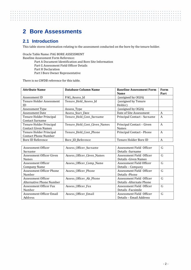
2 Bore Assessments 2.1 Introduction This table stores information relating to the assessment conducted on the bore by the tenure holder. Oracle Table Name: PAG BORE ASSESSMENT Baseline Assessment Form Reference:
Part A Document Identification and Bore Site Information Part G Assessment Field Officer Details Part H Declaration Part I Bore Owner Representative
There is no GWDB reference for this table.
Attribute Name Database Column Name Baseline Assessment Form Name
Form Part
Assessment ID PAG_Assess_Id (assigned by OGIA) Tenure Holder Assessment ID
Tenure_Hold_Assess_Id (assigned by Tenure Holder)
Assessment Type Assess_Type (assigned by OGIA) Assessment Date Assess_Start_Date Date of Site Assessment A Tenure Holder Principal Contact Surname
Tenure_Hold_Cont_Surname Principal Contact - Surname A
Tenure Holder Principal Contact Given Names
Tenure_Hold_Cont_Given_Names Principal Contact – Given Names
A
Tenure Holder Principal Contact Phone Number
Tenure_Hold_Cont_Phone Principal Contact - Phone A
Bore ID Reference Bore_ID_Reference Tenure Holder Bore ID A
Assessment Officer Surname
Assess_Officer_Surname Assessment Field Officer Details -Surname
G
Assessment Officer Given Names
Assess_Officer_Given_Names Assessment Field Officer Details -Given Names
G
Assessment Officer Company Name
Assess_Officer_Comp_Name Assessment Field Officer Details – Company
G
Assessment Officer Phone Number
Assess_Officer_Phone Assessment Field Officer Details -Phone
G
Assessment Officer Alternative Phone Number
Assess_Officer_Alt_Phone Assessment Field Officer Details -Alternate Phone
G
Assessment Officer Fax Number
Assess_Officer_Fax Assessment Field Officer Details -Facsimile
G
Assessment Officer Email Address
Assess_Officer_Email Assessment Field Officer Details – Email Address
G
- 2 -
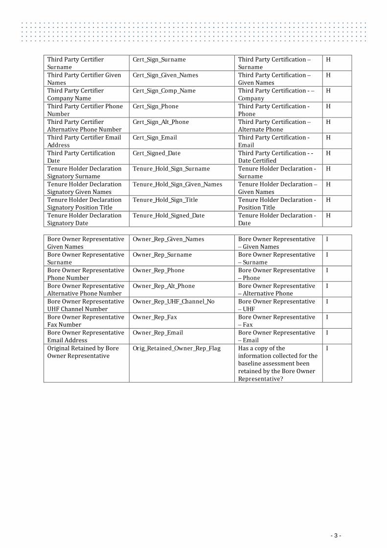
Third Party Certifier Surname
Cert_Sign_Surname Third Party Certification –Surname
H
Third Party Certifier Given Names
Cert_Sign_Given_Names Third Party Certification – Given Names
H
Third Party Certifier Company Name
Cert_Sign_Comp_Name Third Party Certification - – Company
H
Third Party Certifier Phone Number
Cert_Sign_Phone Third Party Certification - Phone
H
Third Party Certifier Alternative Phone Number
Cert_Sign_Alt_Phone Third Party Certification – Alternate Phone
H
Third Party Certifier Email Address
Cert_Sign_Email Third Party Certification - Email
H
Third Party Certification Date
Cert_Signed_Date Third Party Certification - - Date Certified
H
Tenure Holder Declaration Signatory Surname
Tenure_Hold_Sign_Surname Tenure Holder Declaration - Surname
H
Tenure Holder Declaration Signatory Given Names
Tenure_Hold_Sign_Given_Names Tenure Holder Declaration –Given Names
H
Tenure Holder Declaration Signatory Position Title
Tenure_Hold_Sign_Title Tenure Holder Declaration - Position Title
H
Tenure Holder Declaration Signatory Date
Tenure_Hold_Signed_Date Tenure Holder Declaration - Date
H
Bore Owner Representative Given Names
Owner_Rep_Given_Names Bore Owner Representative – Given Names
I
Bore Owner Representative Surname
Owner_Rep_Surname Bore Owner Representative – Surname
I
Bore Owner Representative Phone Number
Owner_Rep_Phone Bore Owner Representative – Phone
I
Bore Owner Representative Alternative Phone Number
Owner_Rep_Alt_Phone Bore Owner Representative – Alternative Phone
I
Bore Owner Representative UHF Channel Number
Owner_Rep_UHF_Channel_No Bore Owner Representative – UHF
I
Bore Owner Representative Fax Number
Owner_Rep_Fax Bore Owner Representative – Fax
I
Bore Owner Representative Email Address
Owner_Rep_Email Bore Owner Representative – Email
I
Original Retained by Bore Owner Representative
Orig_Retained_Owner_Rep_Flag Has a copy of the information collected for the baseline assessment been retained by the Bore Owner Representative?
I
- 3 -
2.2 Description of Attributes
2.2.1 Assessment ID The unique assessment identification number assigned to the assessment by OGIA.
2.2.2 Tenure Holder Assessment ID The unique assessment identification assigned to the assessment by the Tenure Holder. This ID will assist with communication between OGIA and the tenure holder regarding the assessment.
2.2.3 Assessment Type The type of assessment. The following assessment type codes are available. Code Assessment Type BASE Baseline Assessment MON Monitoring Bore INVES Investigation of Bore
2.2.4 Assessment Date The date the assessment was conducted or commenced.
2.2.5 Tenure Holder Principal Contact Surname The surname of the tenure holder principal contact.
2.2.6 Tenure Holder Principal Contact Given Names The given names of the tenure holder principal contact.
2.2.7 Tenure Holder Principal Contact Phone Number The Phone number of the tenure holder principal contact. Please include the area code when necessary.
2.2.8 Bore ID Reference The ID given to the bore by the tenure holder in the first baseline assessment. Any subsequent assessments on the bore irrespective of the tenure holder must use this bore ID. This value in this field must be the same as the Bore ID in the Bore Details table (PAG Bore) and is used to assist with loading data into the OGIA database.
2.2.9 Assessment Officer Surname The surname of the assessment officer responsible for conducting the baseline assessment.
2.2.10 Assessment Officer Given Names The given names of the assessment officer responsible for conducting the baseline assessment.
2.2.11 Assessment Officer Company Name The company name of the assessment officer responsible for conducting the baseline assessment. Note that this may be different from the tenure holder company name if the tenure holder has contracted another company to perform the baseline assessment.
2.2.12 Assessment Officer Phone Number The phone number of the assessment officer responsible for conducting the baseline assessment. Please include the area code when necessary.
2.2.13 Assessment Officer Alternative Phone Number The alternative phone number of the assessment officer responsible for conducting the baseline assessment. Please include the area code when necessary.
- 4 -
2.2.14 Assessment Officer Fax Number The facsimile number of the assessment officer responsible for conducting the baseline assessment. Please include the area code when necessary.
2.2.15 Assessment Officer Email Address The email address of the assessment officer responsible for conducting the baseline assessment.
2.2.16 Third Party Certifier Surname The surname of the person providing third party certification that the baseline assessment has been undertaken in line with appropriate quality control procedures, in compliance with DNRM’s Baseline Assessment Guideline and that persons undertaking the baseline assessment were appropriately qualified.
2.2.17 Third Party Certifier Given Names The given names of the person providing third party certification that the baseline assessment has been undertaken in line with appropriate quality control procedures, in compliance with DNRM’s Baseline Assessment Guideline and that persons undertaking the baseline assessment were appropriately qualified.
2.2.18 Third Party Certifier Company Name The name of the company providing the third party certification.
2.2.19 Third Party Certifier Phone Number The phone number of the certifier providing the third party certification. Please include the area code when necessary.
2.2.20 Third Party Certifier Alternative Phone Number The alternative phone number of the certifier providing the third party certification. Please include the area code when necessary.
2.2.21 Third Party Certifier Email Address The email address of the certifier providing the third party certification.
2.2.22 Third Party Certification Date The date the baseline assessment approved form was signed by the person providing third party certification.
2.2.23 Tenure Holder Declaration Signatory Surname The surname of the person making the tenure holder declaration.
2.2.24 Tenure Holder Declaration Signatory Given Names The given names of the person making the tenure holder declaration.
2.2.25 Tenure Holder Declaration Signatory Position Title The position title of the person making the tenure holder declaration.
2.2.26 Tenure Holder Declaration Signatory Date The date the baseline assessment approved form was signed by the person making the tenure holder declaration.
2.2.27 Bore Owner Representative Surname The surname of the person responsible for providing information to the tenure holder for the baseline assessment.
- 5 -
2.2.28 Bore Owner Representative Given Names The given names of the person responsible for providing information to the tenure holder for the baseline assessment.
2.2.29 Bore Owner Representative Phone Number The phone number of the person responsible for providing information to the tenure holder for the baseline assessment. Please include the area code when necessary.
2.2.30 Bore Owner Representative Alternative Phone Number The alternative phone number of the person responsible for providing information to the tenure holder for the baseline assessment. Please include the area code when necessary.
2.2.31 Bore Owner Representative UHF Channel Number The UHF channel number of the person responsible for providing information to the tenure holder for the baseline assessment.
2.2.32 Bore Owner Representative Fax Number The facsimile number of the person responsible for providing information to the tenure holder for the baseline assessment. Please include the area code when necessary.
2.2.33 Bore Owner Representative Email Address The email address of the person responsible for providing information to the tenure holder for the baseline assessment.
2.2.34 Original Retained by Bore Owner Representative A flag to indicate if a copy of the information collected for the baseline assessment has been retained by the bore owner representative. The following codes are available. Code Original Retained by Bore
Owner Representative Y Yes N No
- 6 -
3 Bore Assessment Documents (Attachments)
3.1 Introduction
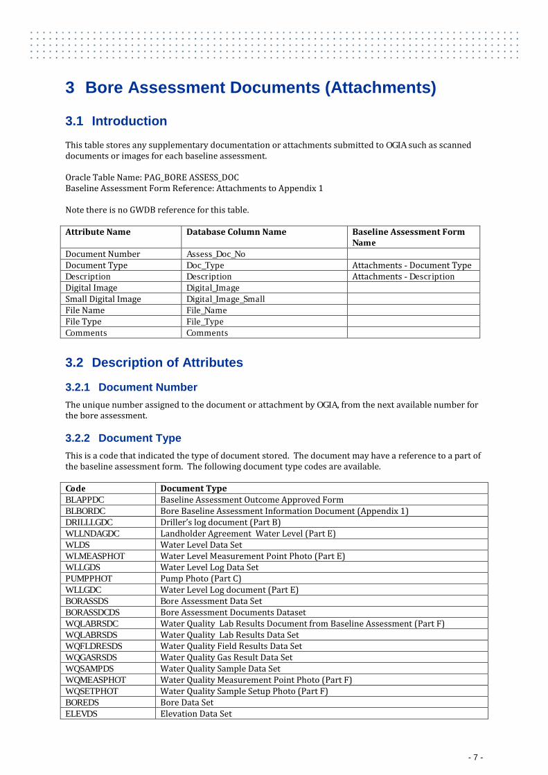
This table stores any supplementary documentation or attachments submitted to OGIA such as scanned documents or images for each baseline assessment. Oracle Table Name: PAG_BORE ASSESS_DOC Baseline Assessment Form Reference: Attachments to Appendix 1 Note there is no GWDB reference for this table. Attribute Name Database Column Name Baseline Assessment Form
Name Document Number Assess_Doc_No Document Type Doc_Type Attachments - Document Type Description Description Attachments - Description Digital Image Digital_Image Small Digital Image Digital_Image_Small File Name File_Name File Type File_Type Comments Comments
3.2 Description of Attributes
3.2.1 Document Number The unique number assigned to the document or attachment by OGIA, from the next available number for the bore assessment.
3.2.2 Document Type This is a code that indicated the type of document stored. The document may have a reference to a part of the baseline assessment form. The following document type codes are available. Code Document Type BLAPPDC Baseline Assessment Outcome Approved Form BLBORDC Bore Baseline Assessment Information Document (Appendix 1) DRILLLGDC Driller’s log document (Part B) WLLNDAGDC Landholder Agreement Water Level (Part E) WLDS Water Level Data Set WLMEASPHOT Water Level Measurement Point Photo (Part E) WLLGDS Water Level Log Data Set PUMPPHOT Pump Photo (Part C) WLLGDC Water Level Log document (Part E) BORASSDS Bore Assessment Data Set BORASSDCDS Bore Assessment Documents Dataset WQLABRSDC Water Quality Lab Results Document from Baseline Assessment (Part F) WQLABRSDS Water Quality Lab Results Data Set WQFLDRESDS Water Quality Field Results Data Set WQGASRSDS Water Quality Gas Result Data Set WQSAMPDS Water Quality Sample Data Set WQMEASPHOT Water Quality Measurement Point Photo (Part F) WQSETPHOT Water Quality Sample Setup Photo (Part F) BOREDS Bore Data Set ELEVDS Elevation Data Set
- 7 -
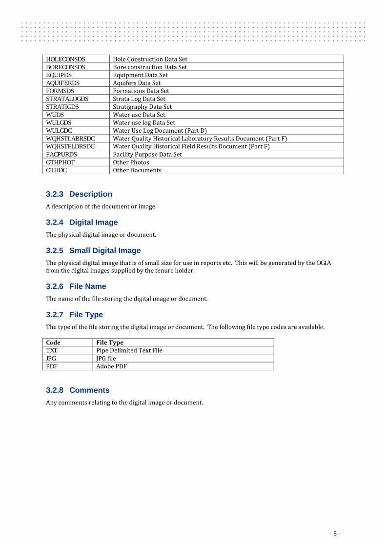
HOLECONSDS Hole Construction Data Set BORECONSDS Bore construction Data Set EQUIPDS Equipment Data Set AQUIFERDS Aquifers Data Set FORMSDS Formations Data Set STRATALOGDS Strata Log Data Set STRATIGDS Stratigraphy Data Set WUDS Water use Data Set WULGDS Water use log Data Set WULGDC Water Use Log Document (Part D) WQHSTLABRSDC Water Quality Historical Laboratory Results Document (Part F) WQHSTFLDRSDC Water Quality Historical Field Results Document (Part F) FACPURDS Facility Purpose Data Set OTHPHOT Other Photos OTHDC Other Documents
3.2.3 Description A description of the document or image.
3.2.4 Digital Image The physical digital image or document.
3.2.5 Small Digital Image The physical digital image that is of small size for use in reports etc. This will be generated by the OGIA from the digital images supplied by the tenure holder.
3.2.6 File Name The name of the file storing the digital image or document.
3.2.7 File Type The type of the file storing the digital image or document. The following file type codes are available. Code File Type TXT Pipe Delimited Text File JPG JPG file PDF Adobe PDF
3.2.8 Comments Any comments relating to the digital image or document.
- 8 -
4 Bore Details
4.1 Introduction
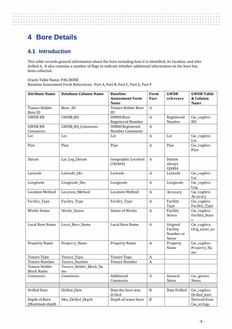
This table records general information about the bore including how it is identified, its location, and who drilled it. It also contains a number of flags to indicate whether additional information on the bore has been collected. Oracle Table Name: PAG BORE Baseline Assessment Form References: Part A, Part B, Part C, Part E, Part F Attribute Name Database Column Name Baseline
Assessment Form Name
Form Part
GWDB reference
GWDB Table & Column Name
Tenure Holder Bore ID
Bore _ID Tenure Holder Bore ID
A
GWDB RN GWDB_RN DNRM Bore Registered Number
A Registered Number
Gw_regdets RN
GWDB RN Comments
GWDB_RN_Comments DNRM Registered Number Comments
A
Lot Lot Lot A Lot Gw_regdets Lot
Plan Plan Plan A Plan Gw_regdets Plan
Datum Lat_Lng_Datum Geographic Location (GDA94)
A Datum always GDA94
Latitude Latitude_Dec Latitude A Latitude Gw_regdets Lat
Longitude Longitude_Dec Longitude A Longitude Gw_regdets Lng
Location Method Location_Method Location Method A Accuracy Gw_regdets Accuracy
Facility_Type Facility_Type Facility_Type A Facility Type
Gw_regdets Faciltiy_Type
Works Status Works_Status Status of Works A Facility Status
Gw_regdets Facility_Status
Local Bore Name Local_Bore_Name Local Bore Name A Original Facility Number or Name
Gw_regdets Orig_name_no
Property Name Property_Name Property Name A Property Name
Gw_regdets Property_Name
Tenure Type Tenure_Type Tenure Type A Tenure Number Tenure_Number Tenure Number A Tenure Holder Block Name
Tenure_Holder_Block_Name
Comments Comments Additional Comments
A General Notes
Gw_gnotes Notes
Drilled Date Drilled_Date Date the bore was
drilled B Date Drilled Gw_regdets
Drilled_date Depth of Bore (Maximum depth
Max_Drilled_Depth Depth of water bore B Derived from Gw_strlogs
- 9 -
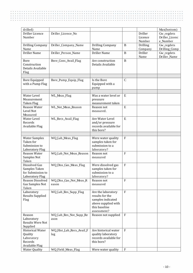
drilled) Max(bottom) Driller Licence Number
Driller_Licence_No Driller Licence Number
Gw_regdets Driller_Licence_Number
Drilling Company Name
Driller_Company_Name Drilling Company Name
B Drilling Company
Gw_regdets Drilling_Comp
Driller Name Driller_Person_Name Driller Name B Driller Name
Gw_regdets Driller_Name
Bore Construction Details Available Flag
Bore_Cons_Avail_Flag Are construction Details Available
B
Bore Equipped with a Pump Flag
Bore_Pump_Equip_Flag Is the Bore Equipped with a pump
C
Water Level Measurement Taken Flag
WL_Meas_Flag Was a water level or pressure measurement taken
E
Reason Water Level Not Measured
WL_Not_Meas_Reason Reason not measured.
E
Water Level Records Available Flag
WL_Recs_Avail_Flag Are Water Level and/or pressure records available for this bore?
E
Water Samples Taken for Submission to Laboratory Flag
WQ_Lab_Meas_Flag Were water quality samples taken for submission to a laboratory?
F
Reason Water Samples Not Taken
WQ_Lab_Not_Meas_Reason Reason not measured
F
Dissolved Gas Samples Taken for Submission to Laboratory Flag
WQ_Diss_Gas_Meas_Flag Were dissolved gas samples taken for submission to a laboratory?
F
Reason Dissolved Gas Samples Not Taken
WQ_Diss_Gas_Not_Meas_Reason
Reason not measured
F
Laboratory Results Supplied Flag
WQ_Lab_Res_Supp_Flag Are the laboratory results for the samples indicated above supplied with this baseline assessment?
F
Reason Laboratory Results Were Not Supplied
WQ_Lab_Res_Not_Supp_Reason
Reason not supplied F
Historical Water Quality Laboratory Records Available Flag
WQ_Hist_Lab_Recs_Avail_Flag
Are historical water quality laboratory records available for this bore?
F
Water Quality WQ_Field_Meas_Flag Were water quality F
- 10 -
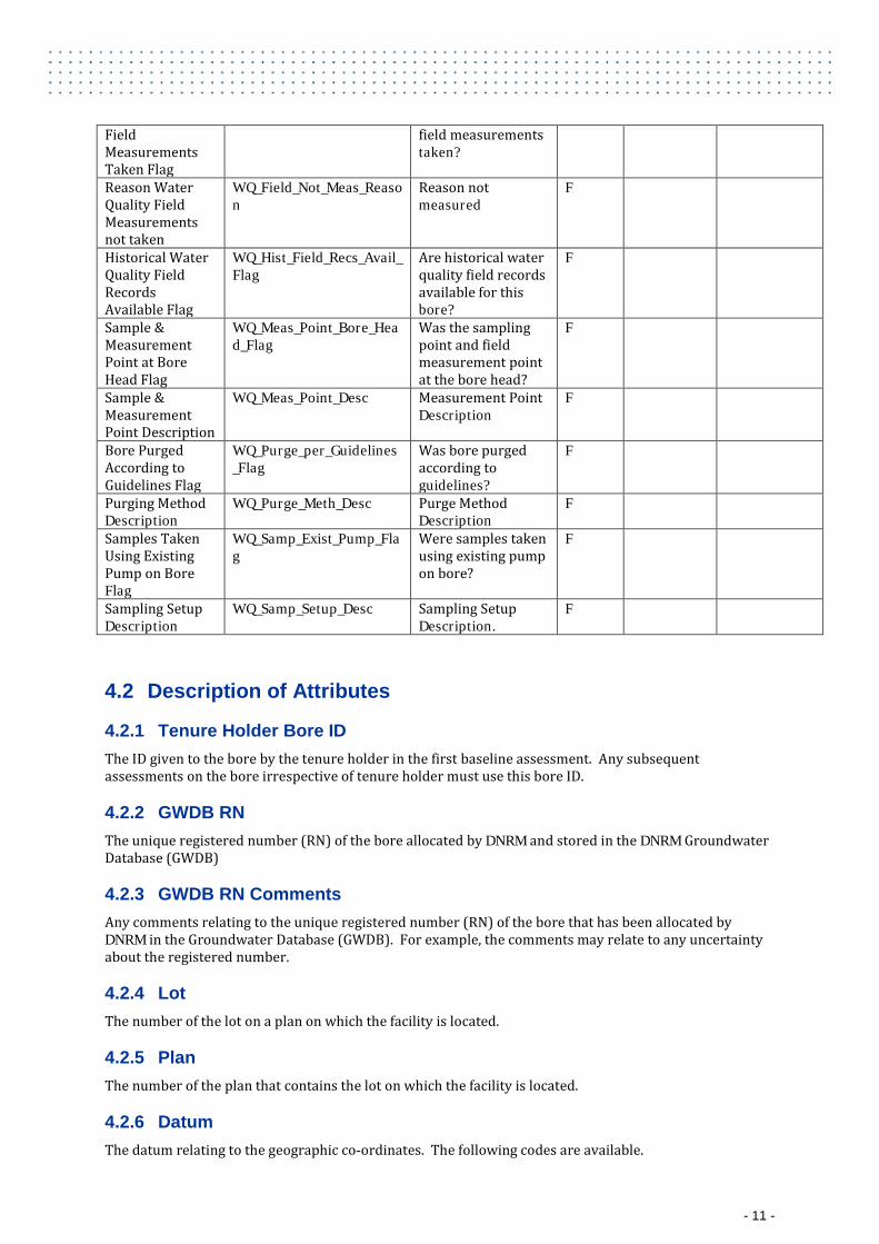
Field Measurements Taken Flag
field measurements taken?
Reason Water Quality Field Measurements not taken
WQ_Field_Not_Meas_Reason
Reason not measured
F
Historical Water Quality Field Records Available Flag
WQ_Hist_Field_Recs_Avail_Flag
Are historical water quality field records available for this bore?
F
Sample & Measurement Point at Bore Head Flag
WQ_Meas_Point_Bore_Head_Flag
Was the sampling point and field measurement point at the bore head?
F
Sample & Measurement Point Description
WQ_Meas_Point_Desc Measurement Point Description
F
Bore Purged According to Guidelines Flag
WQ_Purge_per_Guidelines_Flag
Was bore purged according to guidelines?
F
Purging Method Description
WQ_Purge_Meth_Desc Purge Method Description
F
Samples Taken Using Existing Pump on Bore Flag
WQ_Samp_Exist_Pump_Flag
Were samples taken using existing pump on bore?
F
Sampling Setup Description
WQ_Samp_Setup_Desc Sampling Setup Description.
F
4.2 Description of Attributes
4.2.1 Tenure Holder Bore ID The ID given to the bore by the tenure holder in the first baseline assessment. Any subsequent assessments on the bore irrespective of tenure holder must use this bore ID.
4.2.2 GWDB RN The unique registered number (RN) of the bore allocated by DNRM and stored in the DNRM Groundwater Database (GWDB)
4.2.3 GWDB RN Comments Any comments relating to the unique registered number (RN) of the bore that has been allocated by DNRM in the Groundwater Database (GWDB). For example, the comments may relate to any uncertainty about the registered number.
4.2.4 Lot The number of the lot on a plan on which the facility is located.
4.2.5 Plan The number of the plan that contains the lot on which the facility is located.
4.2.6 Datum The datum relating to the geographic co-ordinates. The following codes are available.
- 11 -
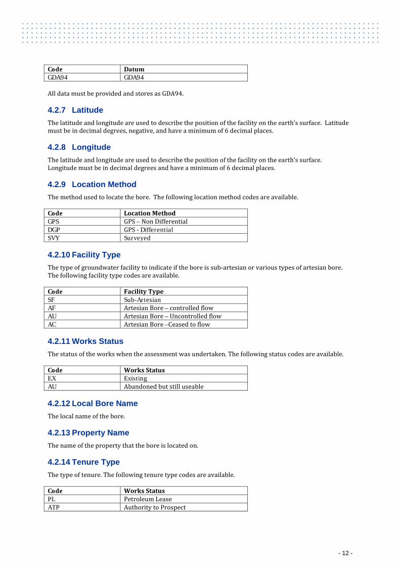
Code Datum GDA94 GDA94 All data must be provided and stores as GDA94.
4.2.7 Latitude The latitude and longitude are used to describe the position of the facility on the earth’s surface. Latitude must be in decimal degrees, negative, and have a minimum of 6 decimal places.
4.2.8 Longitude The latitude and longitude are used to describe the position of the facility on the earth’s surface. Longitude must be in decimal degrees and have a minimum of 6 decimal places.
4.2.9 Location Method The method used to locate the bore. The following location method codes are available. Code Location Method GPS GPS – Non Differential DGP GPS - Differential SVY Surveyed
4.2.10 Facility Type The type of groundwater facility to indicate if the bore is sub-artesian or various types of artesian bore. The following facility type codes are available. Code Facility Type SF Sub-Artesian AF Artesian Bore – controlled flow AU Artesian Bore – Uncontrolled flow AC Artesian Bore –Ceased to flow
4.2.11 Works Status The status of the works when the assessment was undertaken. The following status codes are available. Code Works Status EX Existing AU Abandoned but still useable
4.2.12 Local Bore Name The local name of the bore.
4.2.13 Property Name The name of the property that the bore is located on.
4.2.14 Tenure Type The type of tenure. The following tenure type codes are available. Code Works Status PL Petroleum Lease ATP Authority to Prospect
- 12 -
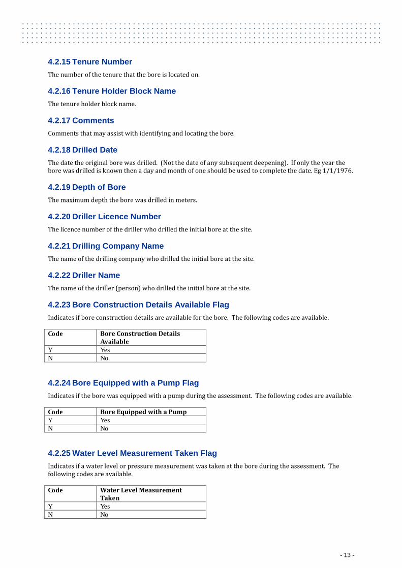
4.2.15 Tenure Number The number of the tenure that the bore is located on.
4.2.16 Tenure Holder Block Name The tenure holder block name.
4.2.17 Comments Comments that may assist with identifying and locating the bore.
4.2.18 Drilled Date The date the original bore was drilled. (Not the date of any subsequent deepening). If only the year the bore was drilled is known then a day and month of one should be used to complete the date. Eg 1/1/1976.
4.2.19 Depth of Bore The maximum depth the bore was drilled in meters.
4.2.20 Driller Licence Number The licence number of the driller who drilled the initial bore at the site.
4.2.21 Drilling Company Name The name of the drilling company who drilled the initial bore at the site.
4.2.22 Driller Name The name of the driller (person) who drilled the initial bore at the site.
4.2.23 Bore Construction Details Available Flag Indicates if bore construction details are available for the bore. The following codes are available. Code Bore Construction Details
Available Y Yes N No
4.2.24 Bore Equipped with a Pump Flag Indicates if the bore was equipped with a pump during the assessment. The following codes are available. Code Bore Equipped with a Pump Y Yes N No
4.2.25 Water Level Measurement Taken Flag Indicates if a water level or pressure measurement was taken at the bore during the assessment. The following codes are available. Code Water Level Measurement
Taken Y Yes N No
- 13 -
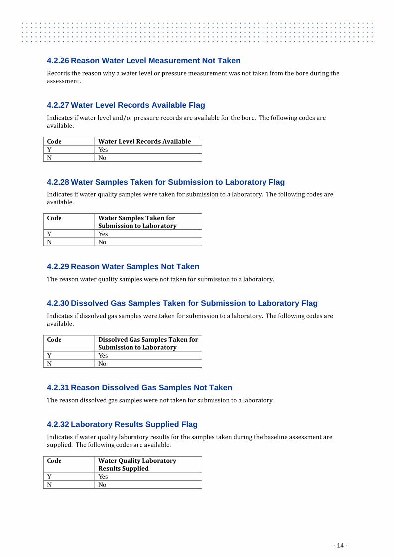
4.2.26 Reason Water Level Measurement Not Taken Records the reason why a water level or pressure measurement was not taken from the bore during the assessment.
4.2.27 Water Level Records Available Flag Indicates if water level and/or pressure records are available for the bore. The following codes are available. Code Water Level Records Available Y Yes N No
4.2.28 Water Samples Taken for Submission to Laboratory Flag Indicates if water quality samples were taken for submission to a laboratory. The following codes are available. Code Water Samples Taken for
Submission to Laboratory Y Yes N No
4.2.29 Reason Water Samples Not Taken The reason water quality samples were not taken for submission to a laboratory.
4.2.30 Dissolved Gas Samples Taken for Submission to Laboratory Flag Indicates if dissolved gas samples were taken for submission to a laboratory. The following codes are available. Code Dissolved Gas Samples Taken for
Submission to Laboratory Y Yes N No
4.2.31 Reason Dissolved Gas Samples Not Taken The reason dissolved gas samples were not taken for submission to a laboratory
4.2.32 Laboratory Results Supplied Flag Indicates if water quality laboratory results for the samples taken during the baseline assessment are supplied. The following codes are available. Code Water Quality Laboratory
Results Supplied Y Yes N No
- 14 -

4.2.33 Reason Laboratory Results were not supplied The reason why water quality laboratory results for the samples taken during the baseline assessment have not been supplied.
4.2.34 Historical Water Quality Laboratory Records Available Flag Indicates if historical water quality laboratory records are available for the bore. The following codes are available. Code Historical Water Quality
Laboratory Records Available Y Yes N No
4.2.35 Water Quality Field Measurements Taken Flag Indicates if water quality field measurements were taken at the bore during the assessment. The following codes are available. Code Water Quality Field
Measurements Taken Y Yes N No
4.2.36 Reason Water Quality Field Measurements Not Taken Records the reason why water quality field measurements were not taken from the bore during the assessment.
4.2.37 Historical Water Quality Field Records Available Flag Indicates if historical water quality field records are available for the bore. The following codes are available. Code Historical Water Quality Field
Records Available Y Yes N No
4.2.38 Sample and Measurement Point at Bore Head Flag Indicates if the sampling point for laboratory water quality samples and measurement point for field water quality measurements was at the bore head. The following codes are available. Code Sample and Measurement Point
at Bore Head Y Yes N No
4.2.39 Sample and Measurement Point Description A description of the location of the sampling point for laboratory water quality samples and measurement point for field water quality measurements, if they were not taken at the bore head. The description must include a GPS reading at the location in the format described in the latitude and longitude sections above. The datum should also be documented (locations must currently be provided in GDA94).
- 15 -
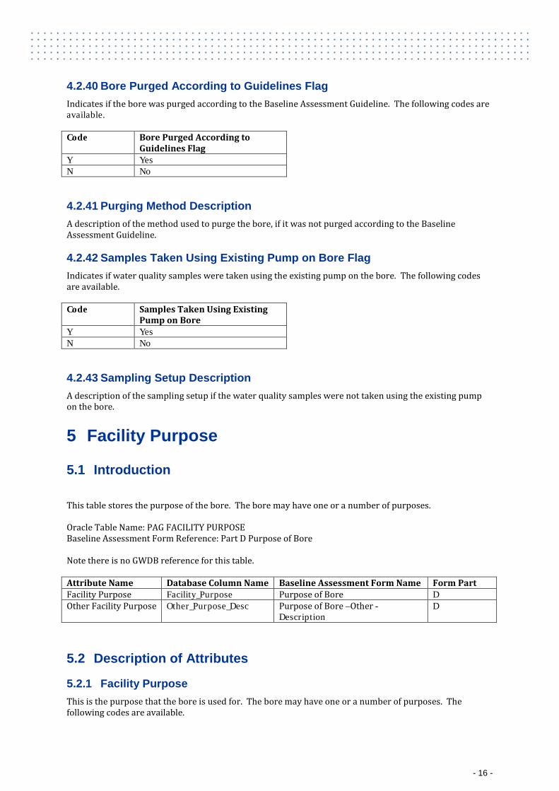
4.2.40 Bore Purged According to Guidelines Flag Indicates if the bore was purged according to the Baseline Assessment Guideline. The following codes are available. Code Bore Purged According to
Guidelines Flag Y Yes N No
4.2.41 Purging Method Description A description of the method used to purge the bore, if it was not purged according to the Baseline Assessment Guideline.
4.2.42 Samples Taken Using Existing Pump on Bore Flag Indicates if water quality samples were taken using the existing pump on the bore. The following codes are available. Code Samples Taken Using Existing
Pump on Bore Y Yes N No
4.2.43 Sampling Setup Description A description of the sampling setup if the water quality samples were not taken using the existing pump on the bore.
5 Facility Purpose
5.1 Introduction
This table stores the purpose of the bore. The bore may have one or a number of purposes. Oracle Table Name: PAG FACILITY PURPOSE Baseline Assessment Form Reference: Part D Purpose of Bore Note there is no GWDB reference for this table. Attribute Name Database Column Name Baseline Assessment Form Name Form Part Facility Purpose Facility_Purpose Purpose of Bore D Other Facility Purpose Other_Purpose_Desc Purpose of Bore –Other -
Description D
5.2 Description of Attributes
5.2.1 Facility Purpose This is the purpose that the bore is used for. The bore may have one or a number of purposes. The following codes are available.
- 16 -
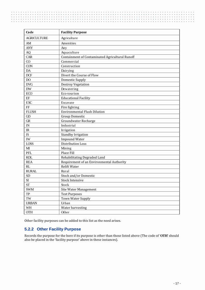
Code Facility Purpose
AGRICULTURE Agriculture AM Amenities ANY Any AQ Aquaculture CAR Containment of Contaminated Agricultural Runoff CO Commercial CON Construction DA Dairying DCF Divert the Course of Flow DO Domestic Supply DVG Destroy Vegetation DW Dewatering ECO Eco-tourism EF Educational Facility EXC Excavate FF Fire fighting FLUSH Environmental Flush Dilution GD Group Domestic GR Groundwater Recharge IN Industrial IR Irrigation IS Standby Irrigation IW Impound Water LOSS Distribution Loss MI Mining PFL Place Fill RDL Rehabilitating Degraded Land REA Requirement of an Environmental Authority RL Relift Water RURAL Rural SD Stock and/or Domestic SI Stock Intensive ST Stock SWM Site Water Management TP Test Purposes TW Town Water Supply URBAN Urban WH Water harvesting OTH Other
Other facility purposes can be added to this list as the need arises.
5.2.2 Other Facility Purpose Records the purpose for the bore if its purpose is other than those listed above (The code of ‘OTH’ should also be placed in the ‘facility purpose’ above in these instances).
- 17 -
6 Water Level
6.1 Introduction
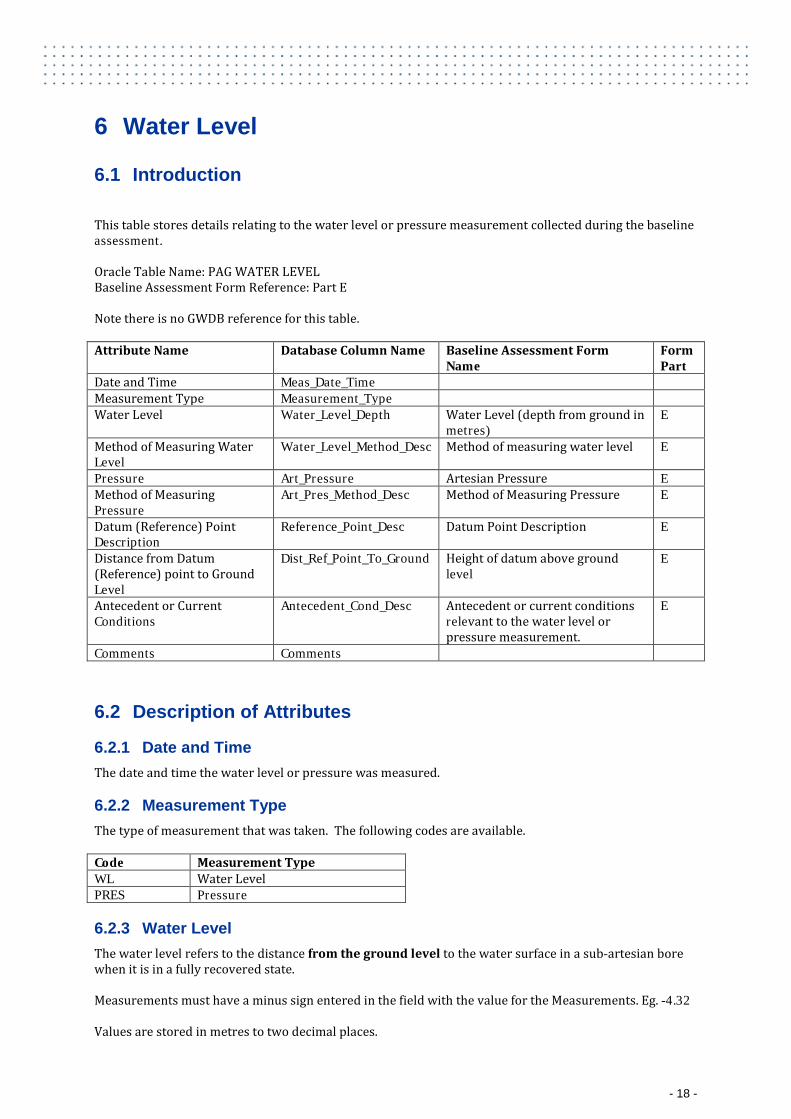
This table stores details relating to the water level or pressure measurement collected during the baseline assessment. Oracle Table Name: PAG WATER LEVEL Baseline Assessment Form Reference: Part E Note there is no GWDB reference for this table. Attribute Name Database Column Name Baseline Assessment Form
Name Form Part
Date and Time Meas_Date_Time Measurement Type Measurement_Type Water Level Water_Level_Depth Water Level (depth from ground in
metres) E
Method of Measuring Water Level
Water_Level_Method_Desc Method of measuring water level E
Pressure Art_Pressure Artesian Pressure E Method of Measuring Pressure
Art_Pres_Method_Desc Method of Measuring Pressure E
Datum (Reference) Point Description
Reference_Point_Desc Datum Point Description E
Distance from Datum (Reference) point to Ground Level
Dist_Ref_Point_To_Ground Height of datum above ground level
E
Antecedent or Current Conditions
Antecedent_Cond_Desc Antecedent or current conditions relevant to the water level or pressure measurement.
E
Comments Comments
6.2 Description of Attributes
6.2.1 Date and Time The date and time the water level or pressure was measured.
6.2.2 Measurement Type The type of measurement that was taken. The following codes are available. Code Measurement Type WL Water Level PRES Pressure
6.2.3 Water Level The water level refers to the distance from the ground level to the water surface in a sub-artesian bore when it is in a fully recovered state. Measurements must have a minus sign entered in the field with the value for the Measurements. Eg. -4.32 Values are stored in metres to two decimal places.
- 18 -
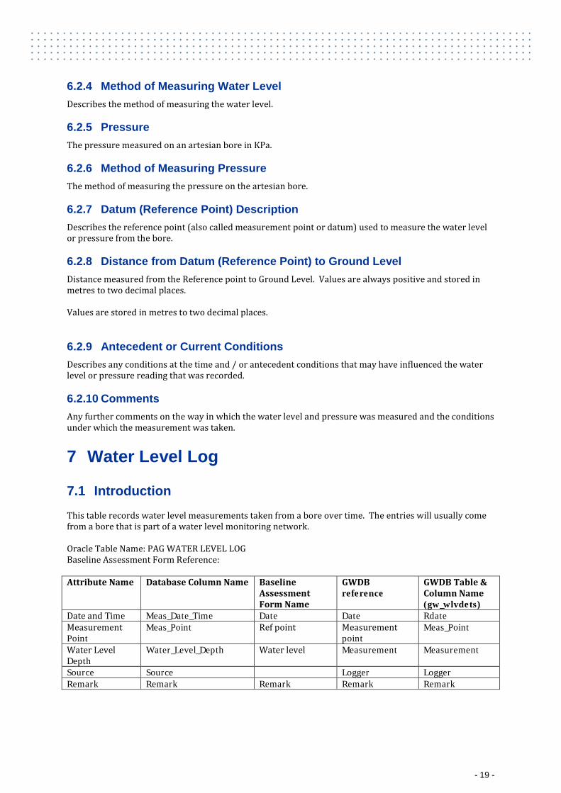
6.2.4 Method of Measuring Water Level Describes the method of measuring the water level.
6.2.5 Pressure The pressure measured on an artesian bore in KPa.
6.2.6 Method of Measuring Pressure The method of measuring the pressure on the artesian bore.
6.2.7 Datum (Reference Point) Description Describes the reference point (also called measurement point or datum) used to measure the water level or pressure from the bore.
6.2.8 Distance from Datum (Reference Point) to Ground Level Distance measured from the Reference point to Ground Level. Values are always positive and stored in metres to two decimal places. Values are stored in metres to two decimal places.
6.2.9 Antecedent or Current Conditions Describes any conditions at the time and / or antecedent conditions that may have influenced the water level or pressure reading that was recorded.
6.2.10 Comments Any further comments on the way in which the water level and pressure was measured and the conditions under which the measurement was taken.
7 Water Level Log
7.1 Introduction
This table records water level measurements taken from a bore over time. The entries will usually come from a bore that is part of a water level monitoring network. Oracle Table Name: PAG WATER LEVEL LOG Baseline Assessment Form Reference: Attribute Name Database Column Name Baseline
Assessment Form Name
GWDB reference
GWDB Table & Column Name (gw_wlvdets)
Date and Time Meas_Date_Time Date Date Rdate Measurement Point
Meas_Point Ref point Measurement point
Meas_Point
Water Level Depth
Water_Level_Depth Water level Measurement Measurement
Source Source Logger Logger Remark Remark Remark Remark Remark
- 19 -
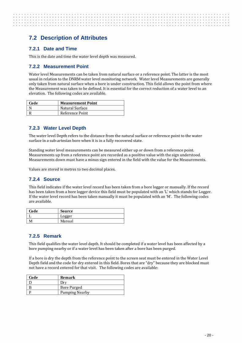
7.2 Description of Attributes
7.2.1 Date and Time This is the date and time the water level depth was measured.
7.2.2 Measurement Point Water level Measurements can be taken from natural surface or a reference point. The latter is the most usual in relation to the DNRM water level monitoring network. Water level Measurements are generally only taken from natural surface when a bore is under construction. This field allows the point from where the Measurement was taken to be defined. It is essential for the correct reduction of a water level to an elevation. The following codes are available. Code Measurement Point N Natural Surface R Reference Point
7.2.3 Water Level Depth The water level Depth refers to the distance from the natural surface or reference point to the water surface in a sub-artesian bore when it is in a fully recovered state. Standing water level measurements can be measured either up or down from a reference point. Measurements up from a reference point are recorded as a positive value with the sign understood. Measurements down must have a minus sign entered in the field with the value for the Measurements. Values are stored in metres to two decimal places.
7.2.4 Source This field indicates if the water level record has been taken from a bore logger or manually. If the record has been taken from a bore logger device this field must be populated with an ‘L’ which stands for Logger. If the water level record has been taken manually it must be populated with an ‘M’. The following codes are available. Code Source L Logger M Manual
7.2.5 Remark This field qualifies the water level depth. It should be completed if a water level has been affected by a bore pumping nearby or if a water level has been taken after a bore has been purged. If a bore is dry the depth from the reference point to the screen seat must be entered in the Water Level Depth field and the code for dry entered in this field. Bores that are “dry” because they are blocked must not have a record entered for that visit. The following codes are available: Code Remark D Dry B Bore Purged P Pumping Nearby
- 20 -
8 Elevation
8.1 Introduction
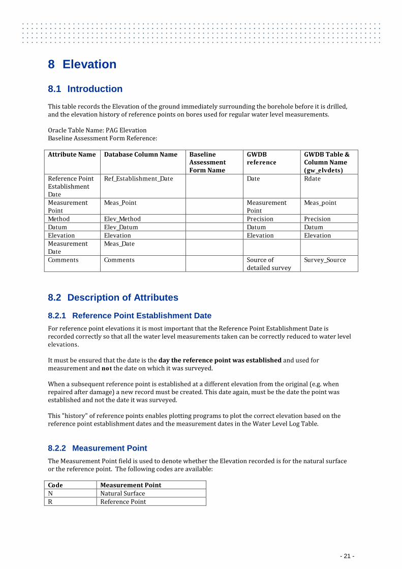
This table records the Elevation of the ground immediately surrounding the borehole before it is drilled, and the elevation history of reference points on bores used for regular water level measurements. Oracle Table Name: PAG Elevation Baseline Assessment Form Reference: Attribute Name Database Column Name Baseline
Assessment Form Name
GWDB reference
GWDB Table & Column Name (gw_elvdets)
Reference Point Establishment Date
Ref_Establishment_Date Date Rdate
Measurement Point
Meas_Point Measurement Point
Meas_point
Method Elev_Method Precision Precision Datum Elev_Datum Datum Datum Elevation Elevation Elevation Elevation Measurement Date
Meas_Date
Comments Comments Source of detailed survey
Survey_Source
8.2 Description of Attributes
8.2.1 Reference Point Establishment Date For reference point elevations it is most important that the Reference Point Establishment Date is recorded correctly so that all the water level measurements taken can be correctly reduced to water level elevations. It must be ensured that the date is the day the reference point was established and used for measurement and not the date on which it was surveyed. When a subsequent reference point is established at a different elevation from the original (e.g. when repaired after damage) a new record must be created. This date again, must be the date the point was established and not the date it was surveyed. This "history" of reference points enables plotting programs to plot the correct elevation based on the reference point establishment dates and the measurement dates in the Water Level Log Table.
8.2.2 Measurement Point The Measurement Point field is used to denote whether the Elevation recorded is for the natural surface or the reference point. The following codes are available: Code Measurement Point N Natural Surface R Reference Point
- 21 -
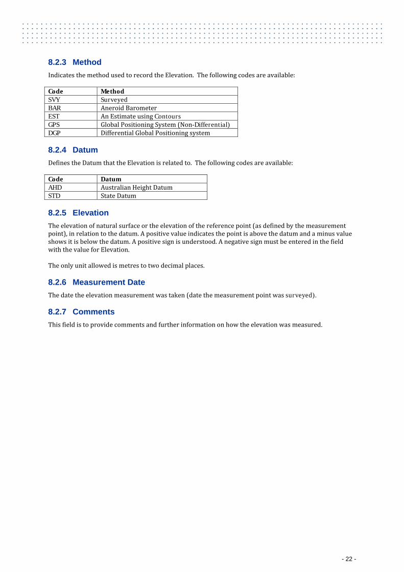
8.2.3 Method Indicates the method used to record the Elevation. The following codes are available: Code Method SVY Surveyed BAR Aneroid Barometer EST An Estimate using Contours GPS Global Positioning System (Non-Differential) DGP Differential Global Positioning system
8.2.4 Datum Defines the Datum that the Elevation is related to. The following codes are available: Code Datum AHD Australian Height Datum STD State Datum
8.2.5 Elevation The elevation of natural surface or the elevation of the reference point (as defined by the measurement point), in relation to the datum. A positive value indicates the point is above the datum and a minus value shows it is below the datum. A positive sign is understood. A negative sign must be entered in the field with the value for Elevation. The only unit allowed is metres to two decimal places.
8.2.6 Measurement Date The date the elevation measurement was taken (date the measurement point was surveyed).
8.2.7 Comments This field is to provide comments and further information on how the elevation was measured.
- 22 -

9 Water Quality Field Results
9.1 Introduction
This table records water quality measurements that have been taken in the field (including dissolved gas measurements). Note that this information must be provided and stored in the units indicated. Oracle Table Name: PAG WQ Field Result Baseline Assessment Form Reference:
Part F: Water Quality – Field Measurements & Field Dissolved Gas Measurements Attribute Name
Database Column Name Baseline Assessment Form Name
Form Part
GWDB reference
GWDB Table & Column Name (gw_fieldqs)
Date and Time Result_Date_Time Date Rdate Result Number Result_No pH PH pH F pH pH Temperature Temp Temp F Temperature Temp Conductivity Elec_Cond Electrical
Conductivity F Conductivity Conduct
HCO3 Alkalinity as CaCO3
HCO3_ALK_CACO3 HCO3 Alkalinity as CaCO3
F
CO3 Alkalinity as CaCO3
CO3_ALK_CACO3 CO3 Alkalinity as CaCO3
F
OH- Alkalinity as CaCO3
OH_ALK_CACO3 OH- Alkalinity as CaCO3
F
Total Alkalinity as CaCO3
TOT_ALK_CACO3 Total Alkalinity as CaCO3
F
Dissolved CO2 Diss_CO2 Dissolved CO2 F Dissolved H2S Diss_H2S Dissolved H2S F Dissolved CH4 Diss_CH4 Dissolved CH4 Dissolved Gas Measurement Method
Diss_Gas_Meas_Method Method F
Dissolved Gas measurement Method Reason
Diss_Gas_Meas_Method_Reason
Reason Method Chosen
F
Water Sample Source
Water_Samp_Source Source Source
Water Sample Method
Water_Samp_Method Remark Samp_Method
Purged Pumped Time
Purge_Pump_time
Purged Pumping Rate
Purge_Pump_rate
Purged Volume Purge_Volume Purged Pump Intake Depth
Purge_Pump_Intake_Depth
Comments Comments
- 23 -
9.2 Description of Attributes
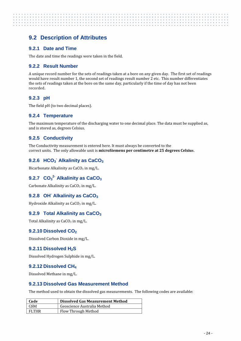
9.2.1 Date and Time The date and time the readings were taken in the field.
9.2.2 Result Number A unique record number for the sets of readings taken at a bore on any given day. The first set of readings would have result number 1, the second set of readings result number 2 etc. This number differentiates the sets of readings taken at the bore on the same day, particularly if the time of day has not been recorded.
9.2.3 pH The field pH (to two decimal places).
9.2.4 Temperature The maximum temperature of the discharging water to one decimal place. The data must be supplied as, and is stored as, degrees Celsius.
9.2.5 Conductivity The Conductivity measurement is entered here. It must always be converted to the correct units. The only allowable unit is microSiemens per centimetre at 25 degrees Celsius.
9.2.6 HCO3- Alkalinity as CaCO3
Bicarbonate Alkalinity as CaCO3 in mg/L.
9.2.7 CO32- Alkalinity as CaCO3
Carbonate Alkalinity as CaCO3 in mg/L.
9.2.8 OH- Alkalinity as CaCO3 Hydroxide Alkalinity as CaCO3 in mg/L.
9.2.9 Total Alkalinity as CaCO3 Total Alkalinity as CaCO3 in mg/L.
9.2.10 Dissolved CO2 Dissolved Carbon Dioxide in mg/L.
9.2.11 Dissolved H2S Dissolved Hydrogen Sulphide in mg/L.
9.2.12 Dissolved CH4 Dissolved Methane in mg/L.
9.2.13 Dissolved Gas Measurement Method The method used to obtain the dissolved gas measurements. The following codes are available: Code Dissolved Gas Measurement Method GSM Geoscience Australia Method FLTHR Flow Through Method
- 24 -
9.2.14 Dissolved Gas Measurement Method Reason The reason the method used to measure dissolved gas was chosen.
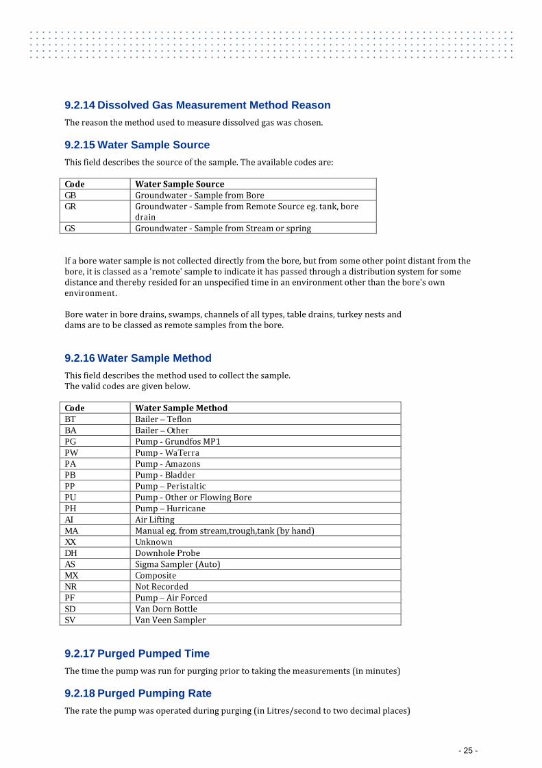
9.2.15 Water Sample Source This field describes the source of the sample. The available codes are: Code Water Sample Source GB Groundwater - Sample from Bore GR Groundwater - Sample from Remote Source eg. tank, bore
drain GS Groundwater - Sample from Stream or spring If a bore water sample is not collected directly from the bore, but from some other point distant from the bore, it is classed as a 'remote' sample to indicate it has passed through a distribution system for some distance and thereby resided for an unspecified time in an environment other than the bore's own environment. Bore water in bore drains, swamps, channels of all types, table drains, turkey nests and dams are to be classed as remote samples from the bore.
9.2.16 Water Sample Method This field describes the method used to collect the sample. The valid codes are given below. Code Water Sample Method BT Bailer – Teflon BA Bailer – Other PG Pump - Grundfos MP1 PW Pump - WaTerra PA Pump - Amazons PB Pump - Bladder PP Pump – Peristaltic PU Pump - Other or Flowing Bore PH Pump – Hurricane AI Air Lifting MA Manual eg. from stream,trough,tank (by hand) XX Unknown DH Downhole Probe AS Sigma Sampler (Auto) MX Composite NR Not Recorded PF Pump – Air Forced SD Van Dorn Bottle SV Van Veen Sampler
9.2.17 Purged Pumped Time The time the pump was run for purging prior to taking the measurements (in minutes)
9.2.18 Purged Pumping Rate The rate the pump was operated during purging (in Litres/second to two decimal places)
- 25 -
9.2.19 Purged Volume The volume of water pumped from the bore during purging (in Litres to two decimal places)
9.2.20 Purged Pump Intake Depth The depth below natural surface of the pump intake during purging (in metres to two decimal places)
9.2.21 Comments Any comments relating to the field water quality measurements taken.
10 Water Quality Laboratory Samples
10.1 Introduction
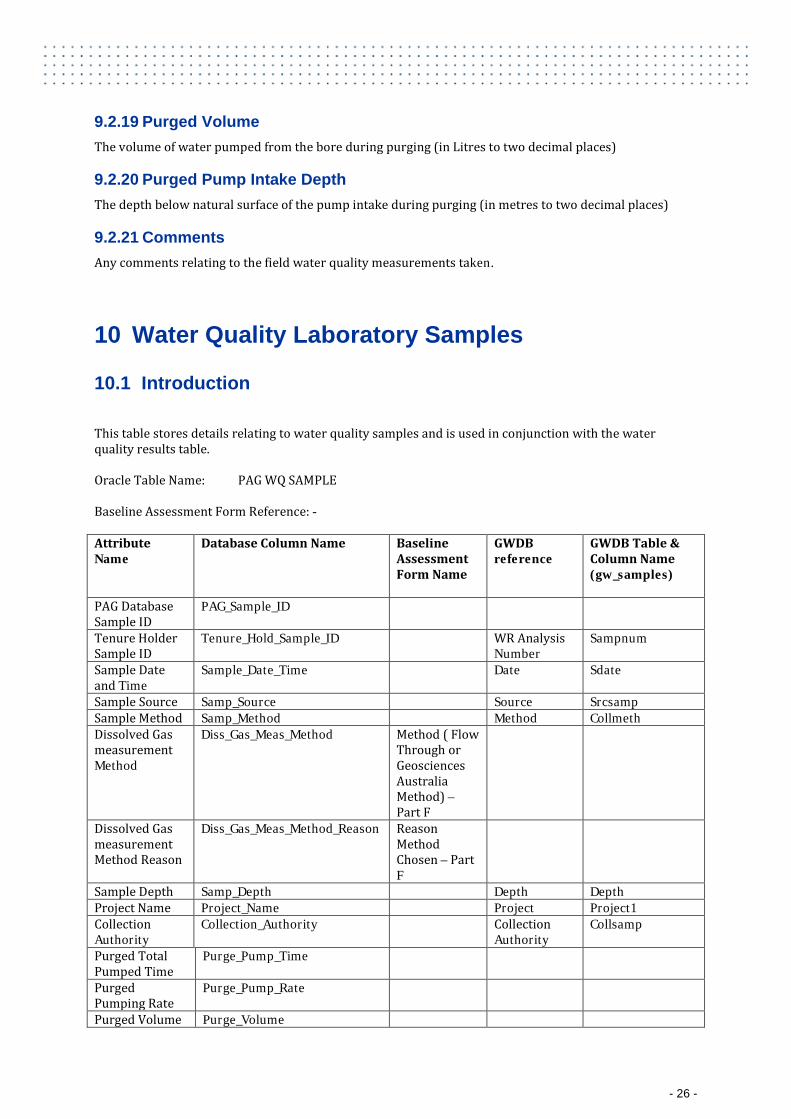
This table stores details relating to water quality samples and is used in conjunction with the water quality results table. Oracle Table Name: PAG WQ SAMPLE Baseline Assessment Form Reference: - Attribute Name
Database Column Name Baseline Assessment Form Name
GWDB reference
GWDB Table & Column Name (gw_samples)
PAG Database Sample ID
PAG_Sample_ID
Tenure Holder Sample ID
Tenure_Hold_Sample_ID WR Analysis Number
Sampnum
Sample Date and Time
Sample_Date_Time Date Sdate
Sample Source Samp_Source Source Srcsamp Sample Method Samp_Method Method Collmeth Dissolved Gas measurement Method
Diss_Gas_Meas_Method Method ( Flow Through or Geosciences Australia Method) – Part F
Dissolved Gas measurement Method Reason
Diss_Gas_Meas_Method_Reason Reason Method Chosen – Part F
Sample Depth Samp_Depth Depth Depth Project Name Project_Name Project Project1 Collection Authority
Collection_Authority Collection Authority
Collsamp
Purged Total Pumped Time
Purge_Pump_Time
Purged Pumping Rate
Purge_Pump_Rate
Purged Volume Purge_Volume
- 26 -
Purged Pump Intake Depth
Purge_Pump_Intake_Depth
Comments Comments
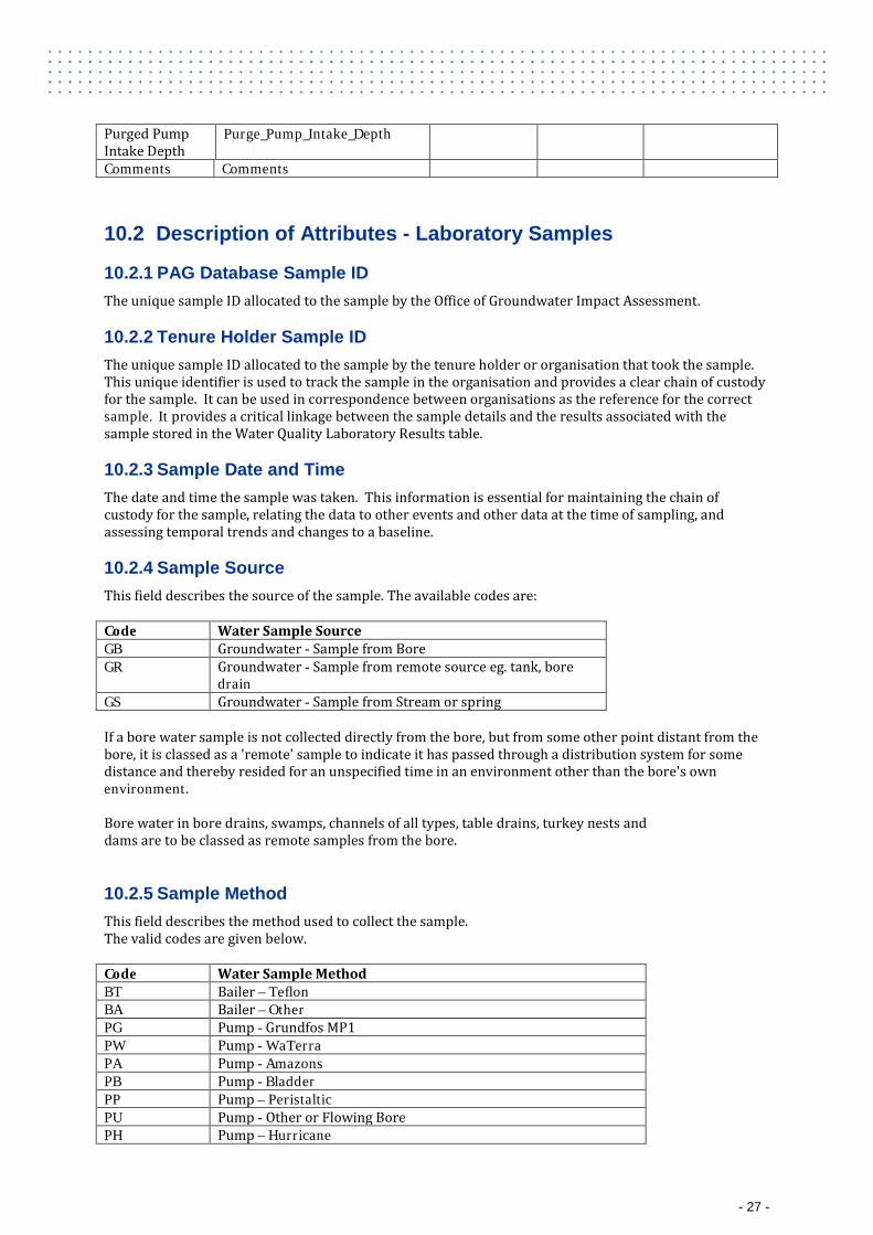
10.2 Description of Attributes - Laboratory Samples
10.2.1 PAG Database Sample ID The unique sample ID allocated to the sample by the Office of Groundwater Impact Assessment.
10.2.2 Tenure Holder Sample ID The unique sample ID allocated to the sample by the tenure holder or organisation that took the sample. This unique identifier is used to track the sample in the organisation and provides a clear chain of custody for the sample. It can be used in correspondence between organisations as the reference for the correct sample. It provides a critical linkage between the sample details and the results associated with the sample stored in the Water Quality Laboratory Results table.
10.2.3 Sample Date and Time The date and time the sample was taken. This information is essential for maintaining the chain of custody for the sample, relating the data to other events and other data at the time of sampling, and assessing temporal trends and changes to a baseline.
10.2.4 Sample Source This field describes the source of the sample. The available codes are: Code Water Sample Source GB Groundwater - Sample from Bore GR Groundwater - Sample from remote source eg. tank, bore
drain GS Groundwater - Sample from Stream or spring If a bore water sample is not collected directly from the bore, but from some other point distant from the bore, it is classed as a 'remote' sample to indicate it has passed through a distribution system for some distance and thereby resided for an unspecified time in an environment other than the bore's own environment. Bore water in bore drains, swamps, channels of all types, table drains, turkey nests and dams are to be classed as remote samples from the bore.
10.2.5 Sample Method This field describes the method used to collect the sample. The valid codes are given below. Code Water Sample Method BT Bailer – Teflon BA Bailer – Other PG Pump - Grundfos MP1 PW Pump - WaTerra PA Pump - Amazons PB Pump - Bladder PP Pump – Peristaltic PU Pump - Other or Flowing Bore PH Pump – Hurricane
- 27 -
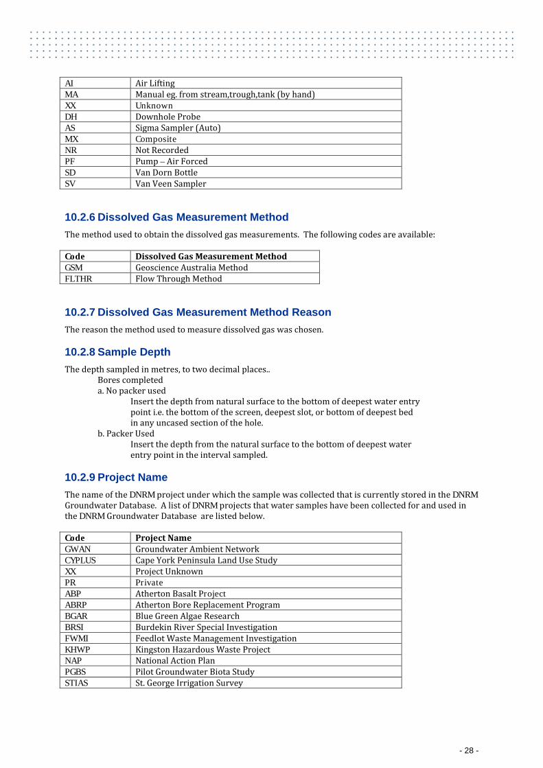
AI Air Lifting MA Manual eg. from stream,trough,tank (by hand) XX Unknown DH Downhole Probe AS Sigma Sampler (Auto) MX Composite NR Not Recorded PF Pump – Air Forced SD Van Dorn Bottle SV Van Veen Sampler
10.2.6 Dissolved Gas Measurement Method The method used to obtain the dissolved gas measurements. The following codes are available: Code Dissolved Gas Measurement Method GSM Geoscience Australia Method FLTHR Flow Through Method
10.2.7 Dissolved Gas Measurement Method Reason The reason the method used to measure dissolved gas was chosen.
10.2.8 Sample Depth The depth sampled in metres, to two decimal places..
Bores completed a. No packer used
Insert the depth from natural surface to the bottom of deepest water entry point i.e. the bottom of the screen, deepest slot, or bottom of deepest bed in any uncased section of the hole.
b. Packer Used Insert the depth from the natural surface to the bottom of deepest water entry point in the interval sampled.
10.2.9 Project Name The name of the DNRM project under which the sample was collected that is currently stored in the DNRM Groundwater Database. A list of DNRM projects that water samples have been collected for and used in the DNRM Groundwater Database are listed below. Code Project Name GWAN Groundwater Ambient Network CYPLUS Cape York Peninsula Land Use Study XX Project Unknown PR Private ABP Atherton Basalt Project ABRP Atherton Bore Replacement Program BGAR Blue Green Algae Research BRSI Burdekin River Special Investigation FWMI Feedlot Waste Management Investigation KHWP Kingston Hazardous Waste Project NAP National Action Plan PGBS Pilot Groundwater Biota Study STIAS St. George Irrigation Survey
- 28 -
If this information has not been derived from the DNRM Groundwater Database then the Project Name should have no entry ie it is to be left blank.
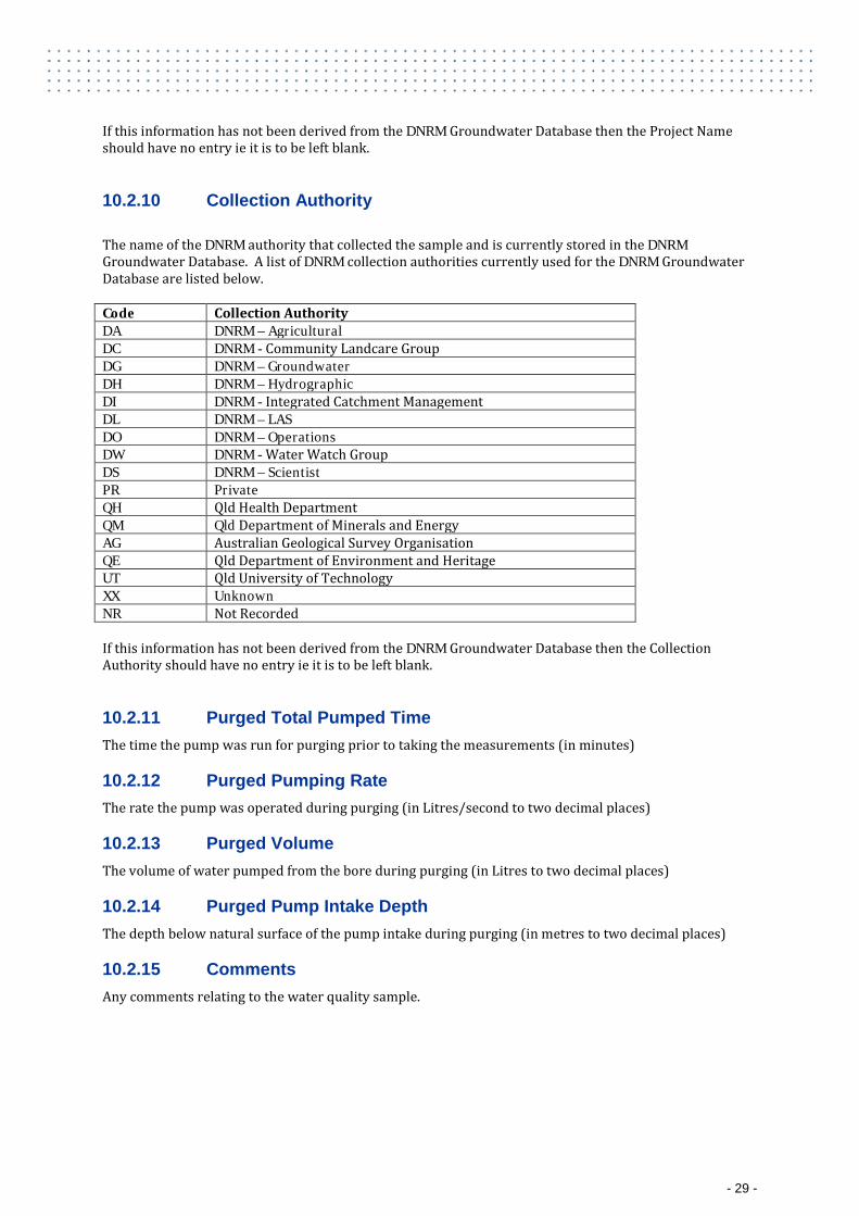
10.2.10 Collection Authority The name of the DNRM authority that collected the sample and is currently stored in the DNRM Groundwater Database. A list of DNRM collection authorities currently used for the DNRM Groundwater Database are listed below. Code Collection Authority DA DNRM – Agricultural DC DNRM - Community Landcare Group DG DNRM – Groundwater DH DNRM – Hydrographic DI DNRM - Integrated Catchment Management DL DNRM – LAS DO DNRM – Operations DW DNRM - Water Watch Group DS DNRM – Scientist PR Private QH Qld Health Department QM Qld Department of Minerals and Energy AG Australian Geological Survey Organisation QE Qld Department of Environment and Heritage UT Qld University of Technology XX Unknown NR Not Recorded If this information has not been derived from the DNRM Groundwater Database then the Collection Authority should have no entry ie it is to be left blank.
10.2.11 Purged Total Pumped Time The time the pump was run for purging prior to taking the measurements (in minutes)
10.2.12 Purged Pumping Rate The rate the pump was operated during purging (in Litres/second to two decimal places)
10.2.13 Purged Volume The volume of water pumped from the bore during purging (in Litres to two decimal places)
10.2.14 Purged Pump Intake Depth The depth below natural surface of the pump intake during purging (in metres to two decimal places)
10.2.15 Comments Any comments relating to the water quality sample.
- 29 -
11 Water Quality Laboratory Results
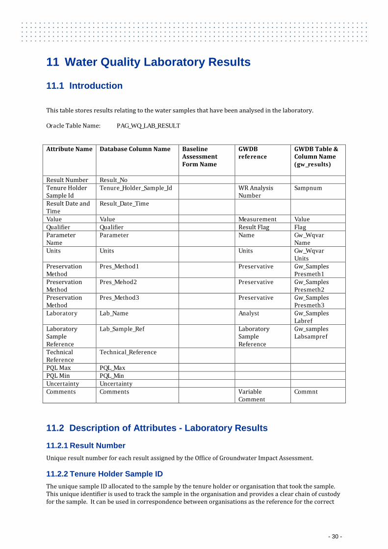
11.1 Introduction
This table stores results relating to the water samples that have been analysed in the laboratory. Oracle Table Name: PAG_WQ_LAB_RESULT Attribute Name Database Column Name Baseline
Assessment Form Name
GWDB reference
GWDB Table & Column Name (gw_results)
Result Number Result_No Tenure Holder Sample Id
Tenure_Holder_Sample_Id WR Analysis Number
Sampnum
Result Date and Time
Result_Date_Time
Value Value Measurement Value Qualifier Qualifier Result Flag Flag Parameter Name
Parameter Name Gw_Wqvar Name
Units Units Units Gw_Wqvar Units
Preservation Method
Pres_Method1 Preservative Gw_Samples Presmeth1
Preservation Method
Pres_Mehod2 Preservative Gw_Samples Presmeth2
Preservation Method
Pres_Method3 Preservative Gw_Samples Presmeth3
Laboratory Lab_Name Analyst Gw_Samples Labref
Laboratory Sample Reference
Lab_Sample_Ref Laboratory Sample Reference
Gw_samples Labsampref
Technical Reference
Technical_Reference
PQL Max PQL_Max PQL Min PQL_Min Uncertainty Uncertainty Comments Comments Variable
Comment Commnt
11.2 Description of Attributes - Laboratory Results
11.2.1 Result Number Unique result number for each result assigned by the Office of Groundwater Impact Assessment.
11.2.2 Tenure Holder Sample ID The unique sample ID allocated to the sample by the tenure holder or organisation that took the sample. This unique identifier is used to track the sample in the organisation and provides a clear chain of custody for the sample. It can be used in correspondence between organisations as the reference for the correct
- 30 -
sample. It provides a critical linkage between the sample details and the results associated with the sample stored in the Water Quality Laboratory Results table.
11.2.3 Result Date and Time The date and time that the parameter was measured in the laboratory.
11.2.4 Value The result recorded by the laboratory for the parameter indicated.
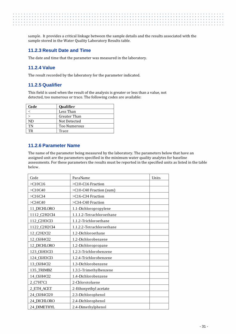
11.2.5 Qualifier This field is used when the result of the analysis is greater or less than a value, not detected, too numerous or trace. The following codes are available: Code Qualifier < Less Than > Greater Than ND Not Detected TN Too Numerous TR Trace
11.2.6 Parameter Name The name of the parameter being measured by the laboratory. The parameters below that have an assigned unit are the parameters specified in the minimum water quality analytes for baseline assessments. For these parameters the results must be reported in the specified units as listed in the table below.
Code ParaName Units >C10C16 >C10-C16 Fraction
>C10C40 >C10-C40 Fraction (sum) >C16C34 >C16-C34 Fraction >C34C40 >C34-C40 Fraction 11_DICHLORO 1.1-Dichloropropylene 1112_C2H2CI4 1.1.1.2-Tetrachloroethane 112_C2H3CI3 1.1.2-Trichloroethane 1122_C2H2CI4 1.1.2.2-Tetrachloroethane 12_C2H2CI2 1.2-Dichloroethane 12_C6H4CI2 1.2-Dichlorobenzene 12_DICHLORO 1.2-Dichloropropane 123_C6H3CI3 1.2.3-Trichlorobenzene 124_C6H3CI3 1.2.4-Trichlorobenzene 13_C6H4CI2 1.3-Dichlorobenzene 135_TRIMBZ 1.3.5-Trimethylbenzene 14_C6H4CI2 1.4-Dichlorobenzene 2_C7H7C1 2-Chlorotoluene 2_ETH_ACET 2-Ethoxyethyl acetate 24_C6H4CI20 2.3-Dichlorophenol 24_DICHLORO 2.4-Dichlorophenol 24_DIMETHYL 2.4-Dimethylphenol
- 31 -
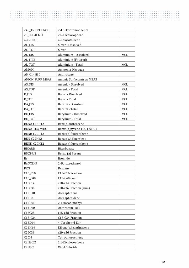
246_TRIBPHENOL 2.4.6-Tribromophenol 26_C6H4CI2O 2.6-Dichlorophenol 4-C7H7C1 4-Chlorotoluene AG_DIS Silver - Dissolved AG_TOT Silver AL_DIS Aluminium - Dissolved MGL
AL_FILT Aluminium (Filtered) AL_TOT Aluminium - Total MGL
AMMNI Ammonia-Nitrogen AN_C14H10 Anthracene ANION_SURF_MBAS Anionic Surfactants as MBAS AS_DIS Arsenic - Dissolved MGL
AS_TOT Arsenic - Total MGL B_DIS Boron - Dissolved MGL B_TOT Boron - Total MGL BA_DIS Barium - Dissolved MGL BA_TOT Barium - Total MGL BE_DIS Beryllium - Dissolved MGL BE_TOT Beryllium - Total MGL BENA_C18H12 Benz(a)anthracene
BENA_TEQ_WHO Benzo(a)pyrene TEQ (WHO) BENB_C20H12 Benzo(b)fluoranthene BEN-C22H12 Benzo(g.h.i)perylene BENK_C20H12 Benzo(k)fluoranthene BICARB Bicarbonate BNZPRN Benzo (a) Pyrene Br Bromide BuOC2H4 2-Butoxyethanol BZN Benzene C10_C16 C10-C16 Fraction C10_C40 C10-C40 (sum) C10C14 c10-c14 Fraction C10C36 c10-c36 Fraction (sum) C12H10 Acenaphthene C12H8 Acenaphthylene C12H9F 2-Fluorobiphenyl C14D10 Anthracene-D10 C15C28 c15-c28 Fraction C16_C34 C16-C34 Fraction C18D14 4-Terphenyl-D14 C22H14 Dibenz(a.h)anthracene C29C36 c29-c36 Fraction C2CI4 Tetrachloroethene C2H2CI2 1.1-Dichloroethene C2H3CI Vinyl Chloride
- 32 -
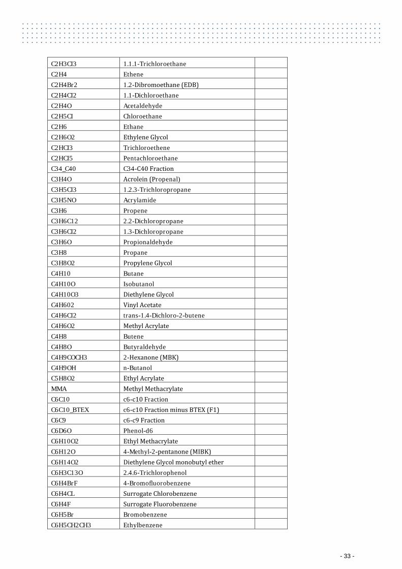
C2H3CI3 1.1.1-Trichloroethane C2H4 Ethene C2H4Br2 1.2-Dibromoethane (EDB) C2H4CI2 1.1-Dichloroethane C2H4O Acetaldehyde C2H5CI Chloroethane C2H6 Ethane C2H6O2 Ethylene Glycol C2HCI3 Trichloroethene C2HCI5 Pentachloroethane C34_C40 C34-C40 Fraction C3H4O Acrolein (Propenal) C3H5CI3 1.2.3-Trichloropropane C3H5NO Acrylamide C3H6 Propene C3H6C12 2.2-Dichloropropane C3H6CI2 1.3-Dichloropropane C3H6O Propionaldehyde C3H8 Propane C3H8O2 Propylene Glycol C4H10 Butane C4H10O Isobutanol C4H10O3 Diethylene Glycol C4H602 Vinyl Acetate C4H6CI2 trans-1.4-Dichloro-2-butene C4H6O2 Methyl Acrylate C4H8 Butene C4H8O Butyraldehyde C4H9COCH3 2-Hexanone (MBK) C4H9OH n-Butanol C5H8O2 Ethyl Acrylate MMA Methyl Methacrylate C6C10 c6-c10 Fraction C6C10_BTEX c6-c10 Fraction minus BTEX (F1) C6C9 c6-c9 Fraction C6D6O Phenol-d6 C6H10O2 Ethyl Methacrylate C6H12O 4-Methyl-2-pentanone (MIBK) C6H14O2 Diethylene Glycol monobutyl ether C6H3C13O 2.4.6-Trichlorophenol C6H4BrF 4-Bromofluorobenzene C6H4CL Surrogate Chlorobenzene C6H4F Surrogate Fluorobenzene C6H5Br Bromobenzene C6H5CH2CH3 Ethylbenzene
- 33 -
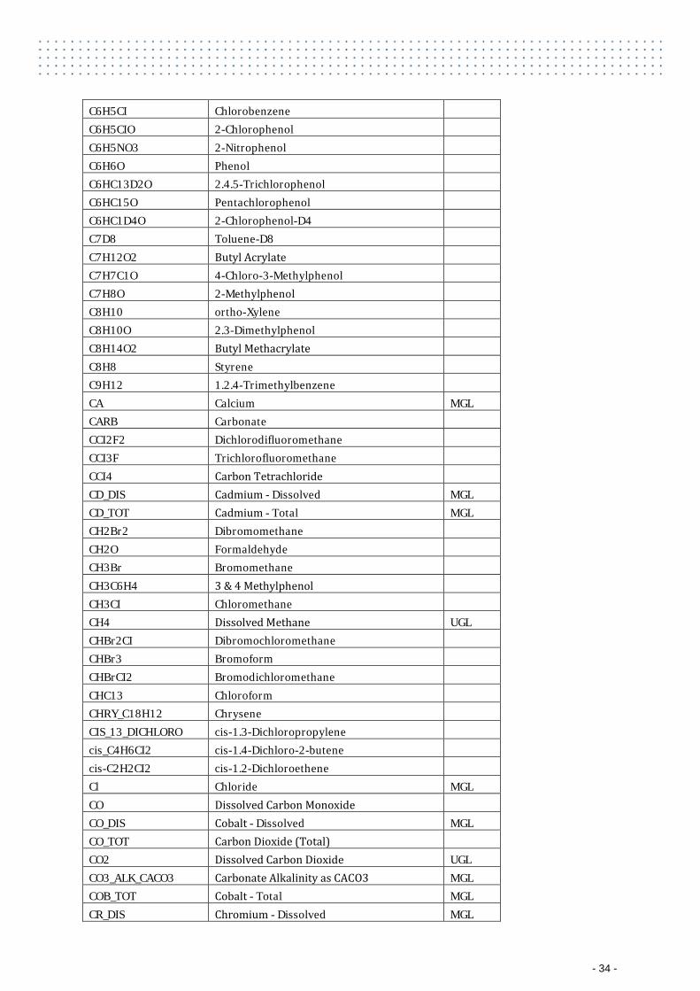
C6H5CI Chlorobenzene C6H5CIO 2-Chlorophenol C6H5NO3 2-Nitrophenol C6H6O Phenol C6HC13D2O 2.4.5-Trichlorophenol C6HC15O Pentachlorophenol C6HC1D4O 2-Chlorophenol-D4 C7D8 Toluene-D8 C7H12O2 Butyl Acrylate C7H7C1O 4-Chloro-3-Methylphenol C7H8O 2-Methylphenol C8H10 ortho-Xylene C8H10O 2.3-Dimethylphenol C8H14O2 Butyl Methacrylate C8H8 Styrene C9H12 1.2.4-Trimethylbenzene CA Calcium MGL
CARB Carbonate CCI2F2 Dichlorodifluoromethane CCI3F Trichlorofluoromethane CCI4 Carbon Tetrachloride CD_DIS Cadmium - Dissolved MGL
CD_TOT Cadmium - Total MGL CH2Br2 Dibromomethane
CH2O Formaldehyde CH3Br Bromomethane CH3C6H4 3 & 4 Methylphenol CH3CI Chloromethane CH4 Dissolved Methane UGL
CHBr2CI Dibromochloromethane CHBr3 Bromoform CHBrCI2 Bromodichloromethane CHC13 Chloroform CHRY_C18H12 Chrysene CIS_13_DICHLORO cis-1.3-Dichloropropylene cis_C4H6CI2 cis-1.4-Dichloro-2-butene cis-C2H2CI2 cis-1.2-Dichloroethene Cl Chloride MGL
CO Dissolved Carbon Monoxide CO_DIS Cobalt - Dissolved MGL
CO_TOT Carbon Dioxide (Total) CO2 Dissolved Carbon Dioxide UGL
CO3_ALK_CACO3 Carbonate Alkalinity as CACO3 MGL COB_TOT Cobalt - Total MGL CR_DIS Chromium - Dissolved MGL
- 34 -
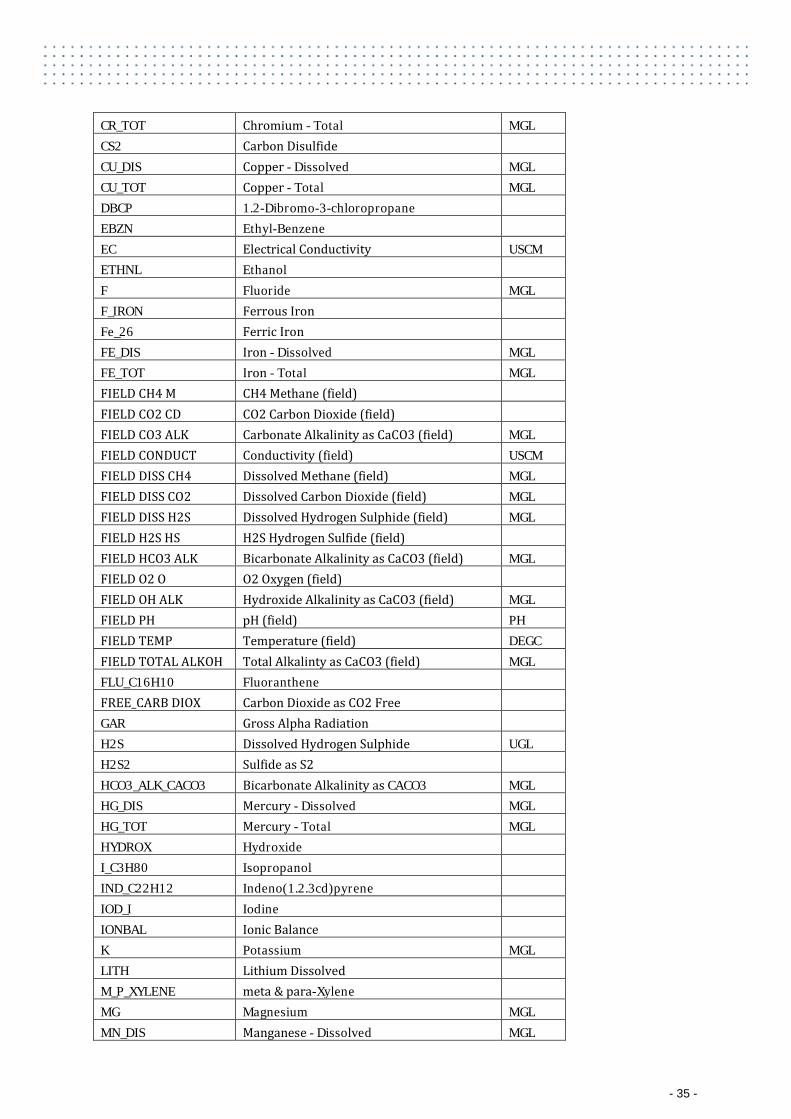
CR_TOT Chromium - Total MGL CS2 Carbon Disulfide
CU_DIS Copper - Dissolved MGL CU_TOT Copper - Total MGL DBCP 1.2-Dibromo-3-chloropropane
EBZN Ethyl-Benzene EC Electrical Conductivity USCM
ETHNL Ethanol F Fluoride MGL
F_IRON Ferrous Iron Fe_26 Ferric Iron FE_DIS Iron - Dissolved MGL
FE_TOT Iron - Total MGL FIELD CH4 M CH4 Methane (field)
FIELD CO2 CD CO2 Carbon Dioxide (field) FIELD CO3 ALK Carbonate Alkalinity as CaCO3 (field) MGL
FIELD CONDUCT Conductivity (field) USCM FIELD DISS CH4 Dissolved Methane (field) MGL FIELD DISS CO2 Dissolved Carbon Dioxide (field) MGL FIELD DISS H2S Dissolved Hydrogen Sulphide (field) MGL FIELD H2S HS H2S Hydrogen Sulfide (field)
FIELD HCO3 ALK Bicarbonate Alkalinity as CaCO3 (field) MGL FIELD O2 O O2 Oxygen (field)
FIELD OH ALK Hydroxide Alkalinity as CaCO3 (field) MGL FIELD PH pH (field) PH FIELD TEMP Temperature (field) DEGC FIELD TOTAL ALKOH Total Alkalinty as CaCO3 (field) MGL FLU_C16H10 Fluoranthene
FREE_CARB DIOX Carbon Dioxide as CO2 Free GAR Gross Alpha Radiation H2S Dissolved Hydrogen Sulphide UGL
H2S2 Sulfide as S2 HCO3_ALK_CACO3 Bicarbonate Alkalinity as CACO3 MGL
HG_DIS Mercury - Dissolved MGL HG_TOT Mercury - Total MGL HYDROX Hydroxide
I_C3H80 Isopropanol IND_C22H12 Indeno(1.2.3cd)pyrene IOD_I Iodine IONBAL Ionic Balance K Potassium MGL
LITH Lithium Dissolved M_P_XYLENE meta & para-Xylene MG Magnesium MGL
MN_DIS Manganese - Dissolved MGL
- 35 -
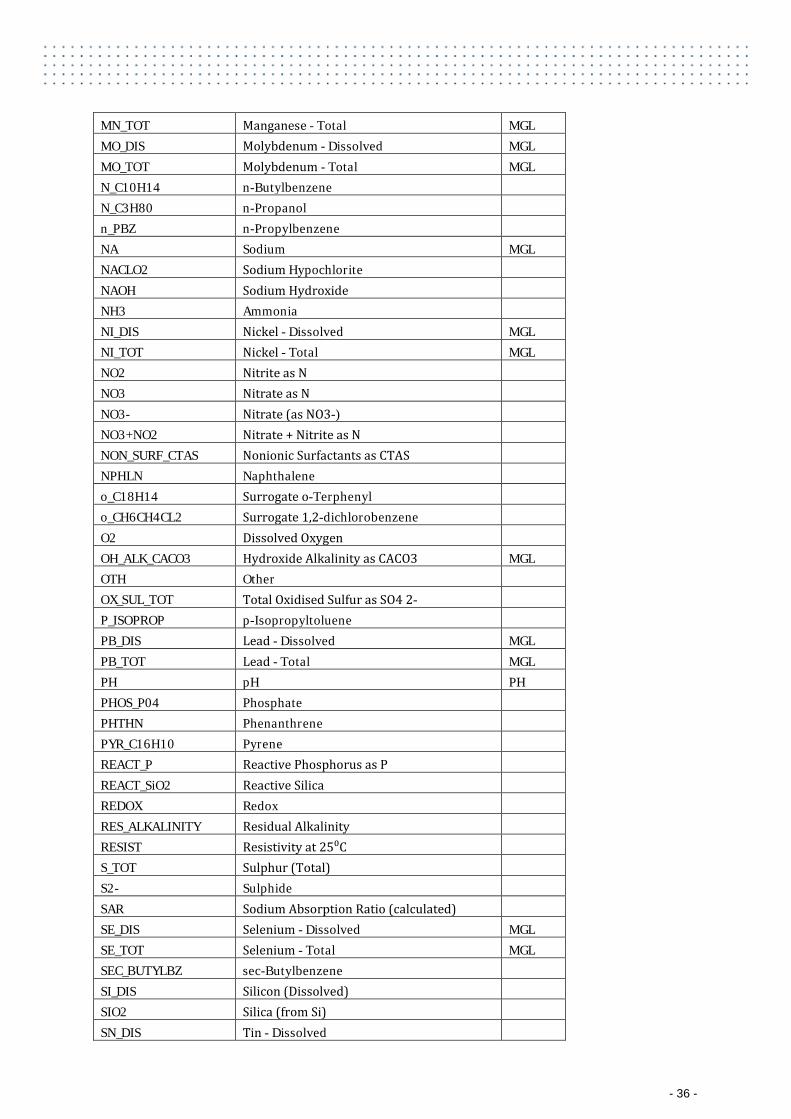
MN_TOT Manganese - Total MGL MO_DIS Molybdenum - Dissolved MGL MO_TOT Molybdenum - Total MGL N_C10H14 n-Butylbenzene
N_C3H80 n-Propanol n_PBZ n-Propylbenzene NA Sodium MGL
NACLO2 Sodium Hypochlorite NAOH Sodium Hydroxide NH3 Ammonia NI_DIS Nickel - Dissolved MGL
NI_TOT Nickel - Total MGL NO2 Nitrite as N
NO3 Nitrate as N NO3- Nitrate (as NO3-) NO3+NO2 Nitrate + Nitrite as N NON_SURF_CTAS Nonionic Surfactants as CTAS NPHLN Naphthalene o_C18H14 Surrogate o-Terphenyl o_CH6CH4CL2 Surrogate 1,2-dichlorobenzene O2 Dissolved Oxygen OH_ALK_CACO3 Hydroxide Alkalinity as CACO3 MGL
OTH Other OX_SUL_TOT Total Oxidised Sulfur as SO4 2- P_ISOPROP p-Isopropyltoluene PB_DIS Lead - Dissolved MGL
PB_TOT Lead - Total MGL PH pH PH PHOS_P04 Phosphate
PHTHN Phenanthrene PYR_C16H10 Pyrene REACT_P Reactive Phosphorus as P REACT_SiO2 Reactive Silica REDOX Redox RES_ALKALINITY Residual Alkalinity RESIST Resistivity at 25⁰C S_TOT Sulphur (Total) S2- Sulphide SAR Sodium Absorption Ratio (calculated) SE_DIS Selenium - Dissolved MGL
SE_TOT Selenium - Total MGL SEC_BUTYLBZ sec-Butylbenzene
SI_DIS Silicon (Dissolved) SIO2 Silica (from Si) SN_DIS Tin - Dissolved
- 36 -
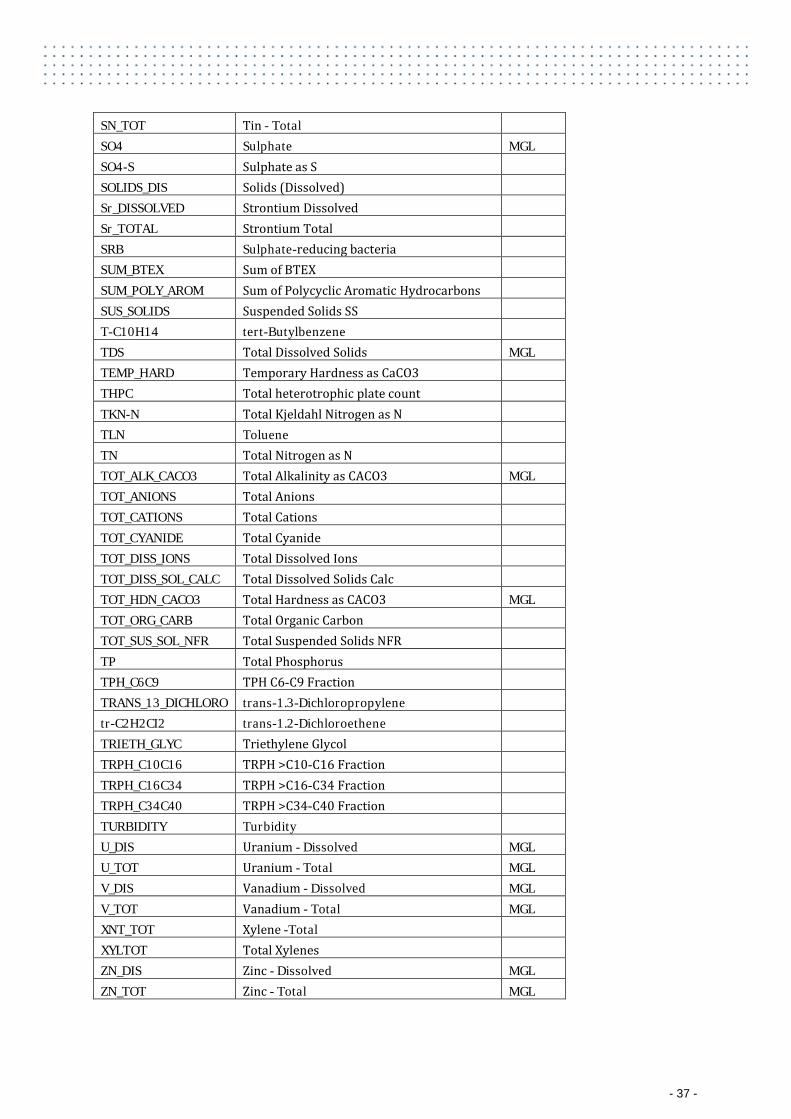
SN_TOT Tin - Total SO4 Sulphate MGL
SO4-S Sulphate as S SOLIDS_DIS Solids (Dissolved) Sr_DISSOLVED Strontium Dissolved Sr_TOTAL Strontium Total SRB Sulphate-reducing bacteria SUM_BTEX Sum of BTEX SUM_POLY_AROM Sum of Polycyclic Aromatic Hydrocarbons SUS_SOLIDS Suspended Solids SS T-C10H14 tert-Butylbenzene TDS Total Dissolved Solids MGL
TEMP_HARD Temporary Hardness as CaCO3 THPC Total heterotrophic plate count TKN-N Total Kjeldahl Nitrogen as N TLN Toluene TN Total Nitrogen as N TOT_ALK_CACO3 Total Alkalinity as CACO3 MGL
TOT_ANIONS Total Anions TOT_CATIONS Total Cations TOT_CYANIDE Total Cyanide TOT_DISS_IONS Total Dissolved Ions TOT_DISS_SOL_CALC Total Dissolved Solids Calc TOT_HDN_CACO3 Total Hardness as CACO3 MGL
TOT_ORG_CARB Total Organic Carbon TOT_SUS_SOL_NFR Total Suspended Solids NFR TP Total Phosphorus TPH_C6C9 TPH C6-C9 Fraction TRANS_13_DICHLORO trans-1.3-Dichloropropylene tr-C2H2CI2 trans-1.2-Dichloroethene TRIETH_GLYC Triethylene Glycol TRPH_C10C16 TRPH >C10-C16 Fraction TRPH_C16C34 TRPH >C16-C34 Fraction TRPH_C34C40 TRPH >C34-C40 Fraction TURBIDITY Turbidity U_DIS Uranium - Dissolved MGL
U_TOT Uranium - Total MGL V_DIS Vanadium - Dissolved MGL V_TOT Vanadium - Total MGL XNT_TOT Xylene -Total
XYLTOT Total Xylenes ZN_DIS Zinc - Dissolved MGL
ZN_TOT Zinc - Total MGL
- 37 -
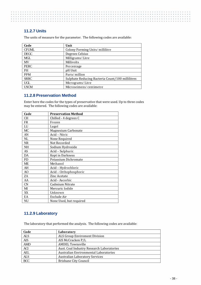
11.2.7 Units The units of measure for the parameter. The following codes are available: Code Unit CFUML Colony Forming Units/millilitre DEGC Degrees Celsius MGL Milligrams/Litre MV Millivolts PERC Percentage PH pH Unit PPM Parts/million SRBC Sulphate Reducing Bacteria Count/100 millilitres UGL Micrograms/Litre USCM Microseimens/centimetre
11.2.8 Preservation Method Enter here the codes for the types of preservative that were used. Up to three codes may be entered. The following codes are available: Code Preservation Method CH Chilled - 4 degrees C FR Frozen LU Lugol MC Magnesium Carbonate AN Acid – Nitric NL None Required NR Not Recorded NH Sodium Hydroxide AS Acid – Sulphuric DA Kept in Darkness PD Potassium Dichromate ME Methanol AH Acid – Hydrochloric AO Acid – Orthophosphoric ZA Zinc Acetate AA Acid - Ascorbic CN Cadmium Nitrate MI Mercuric Iodide XX Unknown EA Exclude Air NU None Used, but required
11.2.9 Laboratory The laboratory that performed the analysis. The following codes are available: Code Laboratory ALS ALS Group Enviroment Division AIS AIS McCracken P/L AMD AMDEL Townsville ACI Aust. Coal Industry Research Laboratories AEL Australian Environmental Laboratories ALS Australian Laboratory Services BCC Brisbane City Council
- 38 -
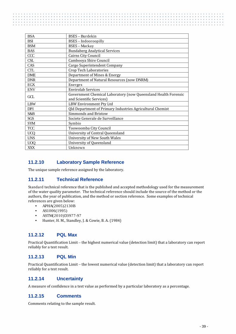
BSA BSES – Burdekin BSI BSES – Indooroopilly BSM BSES – Mackay BAS Bundaberg Analytical Services CCC Cairns City Council CSL Cambooya Shire Council CAS Cargo Superintendent Company CTL Crop Tech Laboratories DME Department of Mines & Energy DNR Department of Natural Resources (now DNRM) EGX Energex ENV Envirolab Services
GCL Government Chemical Laboratory (now Queensland Health Forensic and Scientific Services)
LBW LBW Environment Pty Ltd DPI Qld Department of Primary Industries Agricultural Chemist S&B Simmonds and Bristow SGS Societe Generale de Surveillance SYM Symbio TCC Toowoomba City Council UCQ University of Central Queensland UNS University of New South Wales UOQ University of Queensland XXX Unknown
11.2.10 Laboratory Sample Reference The unique sample reference assigned by the laboratory.
11.2.11 Technical Reference Standard technical reference that is the published and accepted methodology used for the measurement of the water quality parameter. The technical reference should include the source of the method or the authors, the year of publication, and the method or section reference. Some examples of technical references are given below:
· APHA(2005)2130B · AS1006(1995) · ASTM(2010)D3977-97 · Hunter, H. M., Standley, J. & Cowie, B. A. (1984)
11.2.12 PQL Max Practical Quantification Limit – the highest numerical value (detection limit) that a laboratory can report reliably for a test result.
11.2.13 PQL Min Practical Quantification Limit – the lowest numerical value (detection limit) that a laboratory can report reliably for a test result.
11.2.14 Uncertainty A measure of confidence in a test value as performed by a particular laboratory as a percentage.
11.2.15 Comments Comments relating to the sample result.
- 39 -
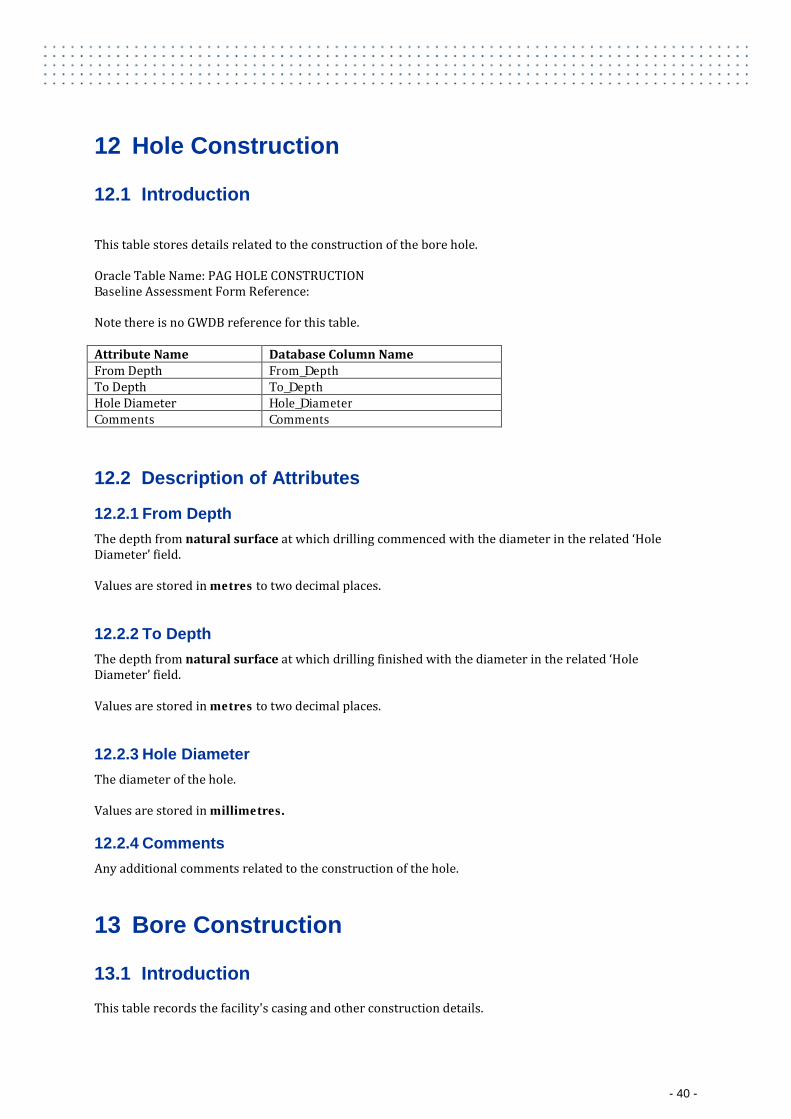
12 Hole Construction
12.1 Introduction
This table stores details related to the construction of the bore hole. Oracle Table Name: PAG HOLE CONSTRUCTION Baseline Assessment Form Reference: Note there is no GWDB reference for this table. Attribute Name Database Column Name From Depth From_Depth To Depth To_Depth Hole Diameter Hole_Diameter Comments Comments
12.2 Description of Attributes
12.2.1 From Depth The depth from natural surface at which drilling commenced with the diameter in the related ‘Hole Diameter’ field. Values are stored in metres to two decimal places.
12.2.2 To Depth The depth from natural surface at which drilling finished with the diameter in the related ‘Hole Diameter’ field. Values are stored in metres to two decimal places.
12.2.3 Hole Diameter The diameter of the hole. Values are stored in millimetres.
12.2.4 Comments Any additional comments related to the construction of the hole.
13 Bore Construction
13.1 Introduction
This table records the facility's casing and other construction details.
- 40 -
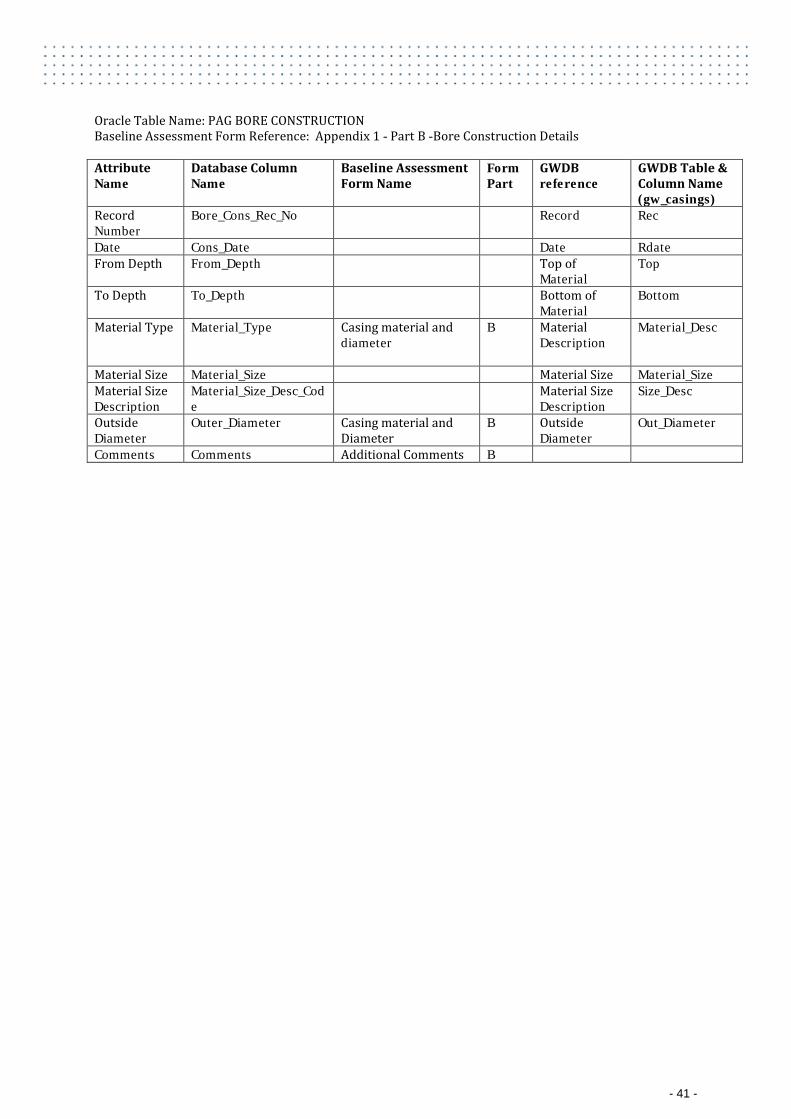
Oracle Table Name: PAG BORE CONSTRUCTION Baseline Assessment Form Reference: Appendix 1 - Part B -Bore Construction Details Attribute Name
Database Column Name
Baseline Assessment Form Name
Form Part
GWDB reference
GWDB Table & Column Name (gw_casings)
Record Number
Bore_Cons_Rec_No Record Rec
Date Cons_Date Date Rdate From Depth From_Depth Top of
Material Top
To Depth To_Depth Bottom of Material
Bottom
Material Type Material_Type Casing material and diameter
B Material Description
Material_Desc
Material Size Material_Size Material Size Material_Size Material Size Description
Material_Size_Desc_Code
Material Size Description
Size_Desc
Outside Diameter
Outer_Diameter Casing material and Diameter
B Outside Diameter
Out_Diameter
Comments Comments Additional Comments B
- 41 -
13.2 Description of Attributes
13.2.1 Record Number The record number keeps the records in the table in a logical sequence for each bore and together with the bore ID uniquely identifies the record. The record number usually starts from one for each bore eg. 1,2,3,4…10 etc
13.2.2 Date The date the casing or other material was inserted in the bore hole.
13.2.3 From Depth This field defines the depth from the natural surface to the top of the material being Described in the record. The ‘From Depth’ must not be greater than the ‘To Depth’. For a string of casing with slots/perforations the total length of the string is entered as one record (perforated section included). A further record/s is then entered identifying where the slots/perforations occur. Values are stored in metres to two decimal places.
13.2.4 To Depth This field defines the depth from the natural surface to the bottom of the material being described in the record. For a string of casing with slots/perforations the total length of the string is entered as one record (perforated section included). A further record/s is then entered identifying where the slots/perforations occur. Values are stored in metres to two decimal places.
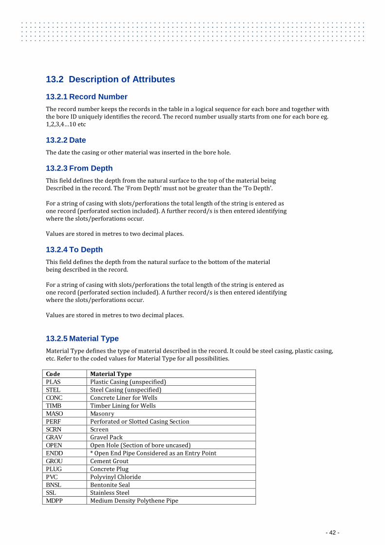
13.2.5 Material Type Material Type defines the type of material described in the record. It could be steel casing, plastic casing, etc. Refer to the coded values for Material Type for all possibilities. Code Material Type PLAS Plastic Casing (unspecified) STEL Steel Casing (unspecified) CONC Concrete Liner for Wells TIMB Timber Lining for Wells MASO Masonry PERF Perforated or Slotted Casing Section SCRN Screen GRAV Gravel Pack OPEN Open Hole (Section of bore uncased) ENDD * Open End Pipe Considered as an Entry Point GROU Cement Grout PLUG Concrete Plug PVC Polyvinyl Chloride BNSL Bentonite Seal SSL Stainless Steel MDPP Medium Density Polythene Pipe
- 42 -
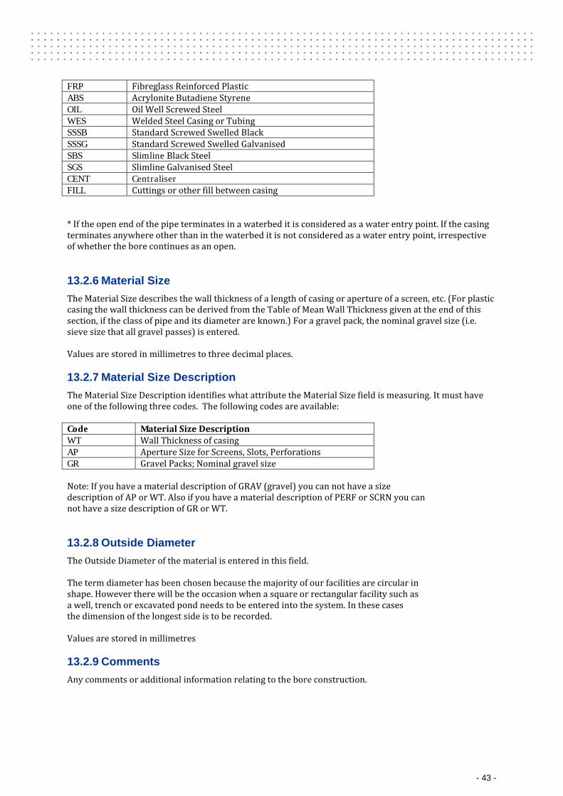
FRP Fibreglass Reinforced Plastic ABS Acrylonite Butadiene Styrene OIL Oil Well Screwed Steel WES Welded Steel Casing or Tubing SSSB Standard Screwed Swelled Black SSSG Standard Screwed Swelled Galvanised SBS Slimline Black Steel SGS Slimline Galvanised Steel CENT Centraliser FILL Cuttings or other fill between casing * If the open end of the pipe terminates in a waterbed it is considered as a water entry point. If the casing terminates anywhere other than in the waterbed it is not considered as a water entry point, irrespective of whether the bore continues as an open.
13.2.6 Material Size The Material Size describes the wall thickness of a length of casing or aperture of a screen, etc. (For plastic casing the wall thickness can be derived from the Table of Mean Wall Thickness given at the end of this section, if the class of pipe and its diameter are known.) For a gravel pack, the nominal gravel size (i.e. sieve size that all gravel passes) is entered. Values are stored in millimetres to three decimal places.
13.2.7 Material Size Description The Material Size Description identifies what attribute the Material Size field is measuring. It must have one of the following three codes. The following codes are available: Code Material Size Description WT Wall Thickness of casing AP Aperture Size for Screens, Slots, Perforations GR Gravel Packs; Nominal gravel size Note: If you have a material description of GRAV (gravel) you can not have a size description of AP or WT. Also if you have a material description of PERF or SCRN you can not have a size description of GR or WT.
13.2.8 Outside Diameter The Outside Diameter of the material is entered in this field. The term diameter has been chosen because the majority of our facilities are circular in shape. However there will be the occasion when a square or rectangular facility such as a well, trench or excavated pond needs to be entered into the system. In these cases the dimension of the longest side is to be recorded. Values are stored in millimetres
13.2.9 Comments Any comments or additional information relating to the bore construction.
- 43 -
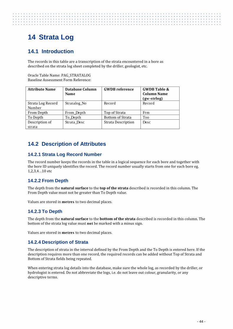
14 Strata Log
14.1 Introduction
The records in this table are a transcription of the strata encountered in a bore as described on the strata log sheet completed by the driller, geologist, etc. Oracle Table Name: PAG_STRATALOG Baseline Assessment Form Reference: Attribute Name Database Column
Name GWDB reference GWDB Table &
Column Name (gw-strlog)
Strata Log Record Number
Stratalog_No Record Record
From Depth From_Depth Top of Strata Frm To Depth To_Depth Bottom of Strata Too Description of strata
Strata_Desc Strata Description Desc
14.2 Description of Attributes
14.2.1 Strata Log Record Number The record number keeps the records in the table in a logical sequence for each bore and together with the bore ID uniquely identifies the record. The record number usually starts from one for each bore eg. 1,2,3,4…10 etc
14.2.2 From Depth The depth from the natural surface to the top of the strata described is recorded in this column. The From Depth value must not be greater than To Depth value. Values are stored in metres to two decimal places.
14.2.3 To Depth The depth from the natural surface to the bottom of the strata described is recorded in this column. The bottom of the strata log value must not be marked with a minus sign. Values are stored in metres to two decimal places.
14.2.4 Description of Strata The description of strata in the interval defined by the From Depth and the To Depth is entered here. If the description requires more than one record, the required records can be added without Top of Strata and Bottom of Strata fields being repeated. When entering strata log details into the database, make sure the whole log, as recorded by the driller, or hydrologist is entered. Do not abbreviate the logs, i.e. do not leave out colour, granularity, or any descriptive terms.
- 44 -
15 Stratigraphy
15.1 Introduction
The data in this table stores the interpreted stratigraphy of the water bore. The stratigraphic interpretation may have been made by the Queensland Department of Minerals and Energy or the Queensland Department of Environment and Resource Management or some other government body or company. Oracle Table Name: PAG_Stratigraphy Baseline Assessment Form Reference: No Reference Attribute Name Database Column Name Baseline
Assessment Form Name
GWDB reference
GWDB Table & Column Name (gw_strtig)
Stratigraphy Number Stratigraphy_No Record Rec Company Name Interpreted_Company_name Source Data_Owner Person Name Interpreted_person_name From Depth From_depth Top of Unit Top To Depth To_depth Bottom of
Unit Bottom
Formation Name Formation_name Description Form_Desc
15.2 Description of Attributes
15.2.1 Stratigraphy Number Every record for a stratigraphic interpretation done by a different organisation must have a unique line number, to keep the records in logical order, and together with the Bore ID and Company Name uniquely identify the record. . Record Numbers will normally start at one ie. 1,2,3,4…10 etc
15.2.2 Company Name The Company Name field describes the organisation that analysed the available data and made the stratigraphic interpretation. The following company names are currently acceptable. Company Name Code Department of Environment and Resource Management
DNR
Department of Mines and Energy DME Australian Geological Survey Organisation AGS BHP Pty Ltd BHP Lockyer Catchment Centre LCC Sunwater SUN Qld Murray Darling Dryland Salinity MDS National Action Plan NAP Prawn Farm Investments PFI Additional companies can be added to this list and allocated a code as required
- 45 -
15.2.3 Person Name The Person Name field describes the person in the organisation that analysed the available data and made the stratigraphy interpretation eg John Smith
15.2.4 From Depth This is the depth below ground level to the top of the stratigraphy unit (in metres). Values are stored in metres to two decimal places.
15.2.5 To Depth This is the depth below ground level to the bottom of the stratigraphy unit (in metres). Values are stored in metres to two decimal places.
15.2.6 Formation Name The Formation Name field stores the name of the stratigraphy unit occupying the zone specified by the From Depth and To Depth.
16 Aquifer
16.1 Introduction
The purpose of this table is to record information about the permeable water bearing beds encountered by a bore penetrating a single geological unit or a number of geological units. Oracle Table Name: PAG_AQUIFER Baseline Assessment Form Reference: Attribute Name
Database Column Name Baseline Assessment Form Name
GWDB reference
GWDB Table & Column Name (gw_aquifrs)
Aquifer Number
Aquifer_No Record Rec
From Depth From_Depth Top of Aquifer Top To Depth To_Depth Bottom of
Aquifer Bottom
Condition Condition_Type Condition Condition Contributing Aquifer
Contributing_Flag Contributing aquifer
Contr
Flow indicator Flow_Above_Ground_Flag Flow Indicator Flow Quality of water in Aquifer
Quality_Desc Quality of water in aquifer
Quality
Yield from aquifer
Yield Yield from aquifer
Yield
Standing water level of aquifer when drilled
SWL Standing Water Level of Aquifer when drilled
SWL
Date of standing water level
SWL_Meas_Date Date of Standing Water Level
RDate
Formation Name
Formation_Name Part B – Geological
Formation Name
Form_Desc
- 46 -
Formation from which water is accessed.
16.2 Description of Attributes
16.2.1 Aquifer Number This is a number indicating the order in which the aquifers were encountered. . Eg. 1,2,3,4 etc. Together with the Tenure Holder Bore ID it uniquely identifies the record.
16.2.2 From Depth The depth from natural surface to the top of the aquifer described is recorded in this field. Values are stored in metres to two decimal places.
16.2.3 To Depth The depth from natural surface to the bottom of the aquifer described is recorded in this field. Values are stored in metres to two decimal places.
16.2.4 Condition Condition refers to the hydrological and physical condition of the material in the bed. However the hydrological aspect is dominant. Basically the condition is determined by the mechanism by which water is transmitted in the rock mass i.e. is the water transmitted via pores, between grains or via fractures in the rock mass. The following codes are available. Porous Rocks Code Condition UC Unconsolidated PS Consolidated SC Semi-Consolidated Fractured Rocks Code Condition FR Fractured VS Vesicular CV Cavernous WZ Weathered Zone
16.2.5 Contributing Aquifer The Contributing Aquifer field is completed with Y (Yes) if the Aquifer contributes to the supply in the completed bore. If the aquifer is not contributing to the supply of the completed bore the field is completed with N (No). The following codes are available: Code Contributing Aquifer Y Yes N No
- 47 -
16.2.6 Flow indicator In many cases it is known that an aquifer has yielded a flowing water supply, however there are no details of the static head. This field indicates whether or not the water level of the aquifer rose above ground level. ie. Whether or not a flow was encountered. If a flow is encountered in the aquifer specified, Y is entered. If the water level is below ground level N is entered. The following codes are available: Code Flow Indicator Y Yes N No
16.2.7 Quality description of water in Aquifer This field is used to indicate the quality of water in an aquifer. If a full water sample has been taken the Sample/Analysis Number may be entered. eg SEE ANAL 123456. If field measurements such as conductivity have been taken, these measurements must be entered in the water quality field measurement table. A note indicating this may be made in this field. eg. SEE FIELD MEAS. In many cases, only a comment regarding the quality of the water is made eg. BRACKISH. In these cases, the comment should be entered.
16.2.8 Yield from aquifer The Yield from Aquifer field stores an estimate of the yield from the aquifer. The estimate may be obtained by bailing, air test, pump test, flow test etc. Values are stored in litres/second to two decimal place.
16.2.9 Standing water level of aquifer when drilled The Standing Water Level of Aquifer when Drilled field is used to record the water level or static head measured from natural surface for each aquifer, when the bore was drilled. Water levels below ground level must be entered as a negative. If the bore is flowing the static head is entered as a positive measurement above ground level. Values are stored in metres to two decimal places.
16.2.10 Date of standing water level This field records the date on which the standing water level or static head stored in the 'standing water level of aquifer when drilled' field was taken.
16.2.11 Formation Name Formation Name is the name of the geological unit containing the aquifer being recorded. The source of data to be entered in this field is the formation names on published maps or in published documents. Alluvium is to be treated as a lithological formation. The Formation Name is to consist of the name of the river, creek or geographic feature commonly used to describe the alluvium of an area. The name should be entered in full eg Black River Alluvium
- 48 -
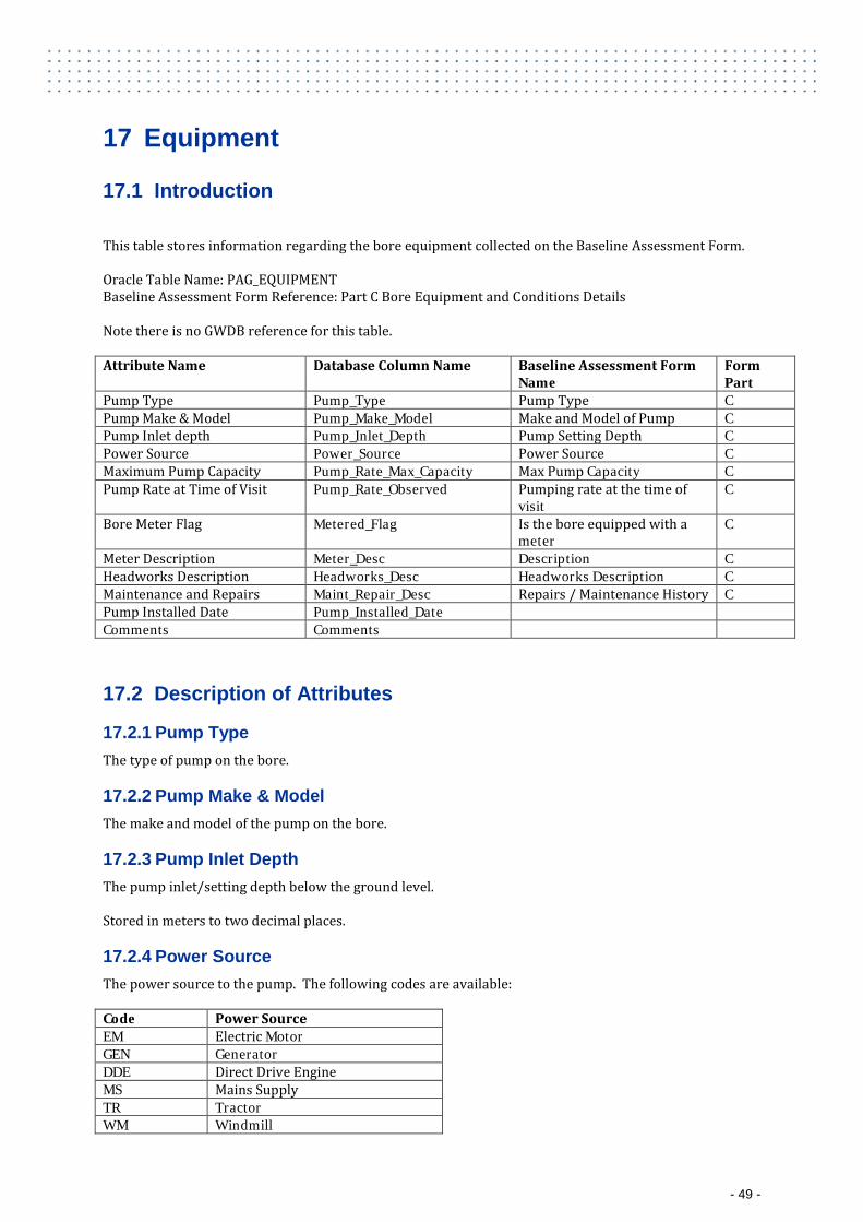
17 Equipment
17.1 Introduction
This table stores information regarding the bore equipment collected on the Baseline Assessment Form. Oracle Table Name: PAG_EQUIPMENT Baseline Assessment Form Reference: Part C Bore Equipment and Conditions Details Note there is no GWDB reference for this table. Attribute Name Database Column Name Baseline Assessment Form
Name Form Part
Pump Type Pump_Type Pump Type C Pump Make & Model Pump_Make_Model Make and Model of Pump C Pump Inlet depth Pump_Inlet_Depth Pump Setting Depth C Power Source Power_Source Power Source C Maximum Pump Capacity Pump_Rate_Max_Capacity Max Pump Capacity C Pump Rate at Time of Visit Pump_Rate_Observed Pumping rate at the time of
visit C
Bore Meter Flag Metered_Flag Is the bore equipped with a meter
C
Meter Description Meter_Desc Description C Headworks Description Headworks_Desc Headworks Description C Maintenance and Repairs Maint_Repair_Desc Repairs / Maintenance History C Pump Installed Date Pump_Installed_Date Comments Comments
17.2 Description of Attributes
17.2.1 Pump Type The type of pump on the bore.
17.2.2 Pump Make & Model The make and model of the pump on the bore.
17.2.3 Pump Inlet Depth The pump inlet/setting depth below the ground level. Stored in meters to two decimal places.
17.2.4 Power Source The power source to the pump. The following codes are available: Code Power Source EM Electric Motor GEN Generator DDE Direct Drive Engine MS Mains Supply TR Tractor WM Windmill
- 49 -
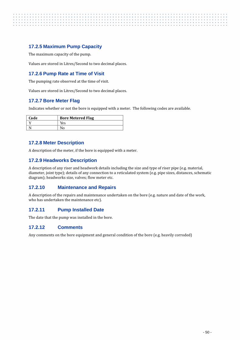
17.2.5 Maximum Pump Capacity The maximum capacity of the pump. Values are stored in Litres/Second to two decimal places.
17.2.6 Pump Rate at Time of Visit The pumping rate observed at the time of visit. Values are stored in Litres/Second to two decimal places.
17.2.7 Bore Meter Flag Indicates whether or not the bore is equipped with a meter. The following codes are available. Code Bore Metered Flag Y Yes N No
17.2.8 Meter Description A description of the meter, if the bore is equipped with a meter.
17.2.9 Headworks Description A description of any riser and headwork details including the size and type of riser pipe (e.g. material, diameter, joint type); details of any connection to a reticulated system (e.g. pipe sizes, distances, schematic diagram); headworks size, valves; flow meter etc.
17.2.10 Maintenance and Repairs A description of the repairs and maintenance undertaken on the bore (e.g. nature and date of the work, who has undertaken the maintenance etc).
17.2.11 Pump Installed Date The date that the pump was installed in the bore.
17.2.12 Comments Any comments on the bore equipment and general condition of the bore (e.g. heavily corroded)
- 50 -
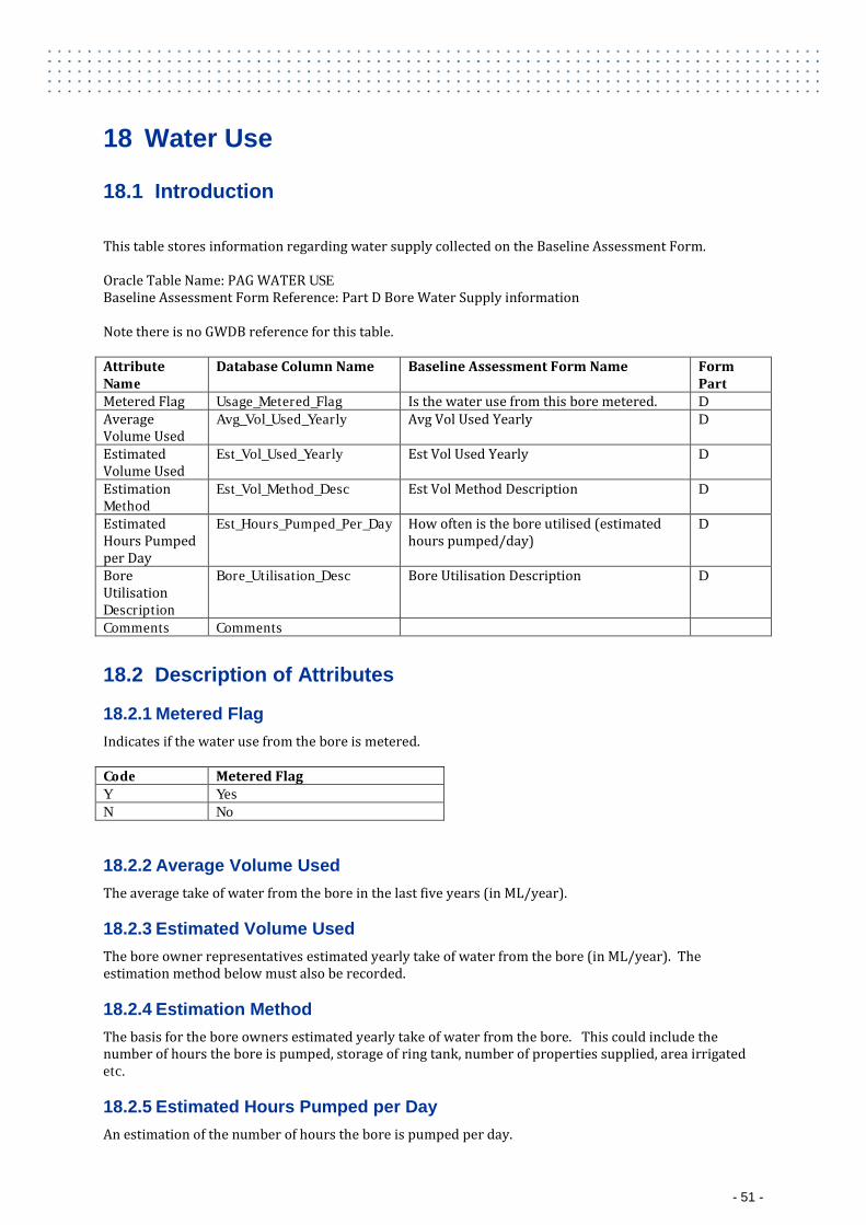
18 Water Use
18.1 Introduction
This table stores information regarding water supply collected on the Baseline Assessment Form. Oracle Table Name: PAG WATER USE Baseline Assessment Form Reference: Part D Bore Water Supply information Note there is no GWDB reference for this table. Attribute Name
Database Column Name Baseline Assessment Form Name Form Part
Metered Flag Usage_Metered_Flag Is the water use from this bore metered. D Average Volume Used
Avg_Vol_Used_Yearly Avg Vol Used Yearly D
Estimated Volume Used
Est_Vol_Used_Yearly Est Vol Used Yearly D
Estimation Method
Est_Vol_Method_Desc Est Vol Method Description D
Estimated Hours Pumped per Day
Est_Hours_Pumped_Per_Day How often is the bore utilised (estimated hours pumped/day)
D
Bore Utilisation Description
Bore_Utilisation_Desc Bore Utilisation Description D
Comments Comments
18.2 Description of Attributes
18.2.1 Metered Flag Indicates if the water use from the bore is metered. Code Metered Flag Y Yes N No
18.2.2 Average Volume Used The average take of water from the bore in the last five years (in ML/year).
18.2.3 Estimated Volume Used The bore owner representatives estimated yearly take of water from the bore (in ML/year). The estimation method below must also be recorded.
18.2.4 Estimation Method The basis for the bore owners estimated yearly take of water from the bore. This could include the number of hours the bore is pumped, storage of ring tank, number of properties supplied, area irrigated etc.
18.2.5 Estimated Hours Pumped per Day An estimation of the number of hours the bore is pumped per day.
- 51 -
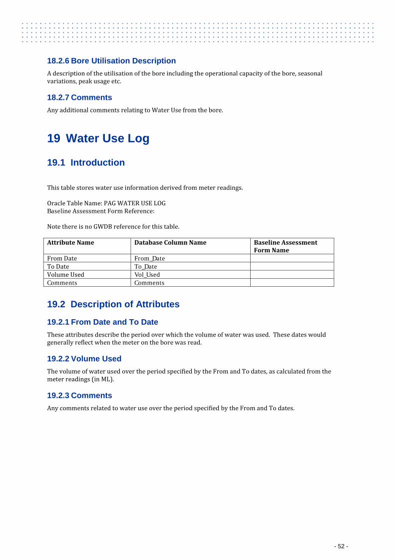
18.2.6 Bore Utilisation Description A description of the utilisation of the bore including the operational capacity of the bore, seasonal variations, peak usage etc.
18.2.7 Comments Any additional comments relating to Water Use from the bore.
19 Water Use Log
19.1 Introduction
This table stores water use information derived from meter readings. Oracle Table Name: PAG WATER USE LOG Baseline Assessment Form Reference: Note there is no GWDB reference for this table. Attribute Name Database Column Name Baseline Assessment
Form Name From Date From_Date To Date To_Date Volume Used Vol_Used Comments Comments
19.2 Description of Attributes
19.2.1 From Date and To Date These attributes describe the period over which the volume of water was used. These dates would generally reflect when the meter on the bore was read.
19.2.2 Volume Used The volume of water used over the period specified by the From and To dates, as calculated from the meter readings (in ML).
19.2.3 Comments Any comments related to water use over the period specified by the From and To dates.
- 52 -
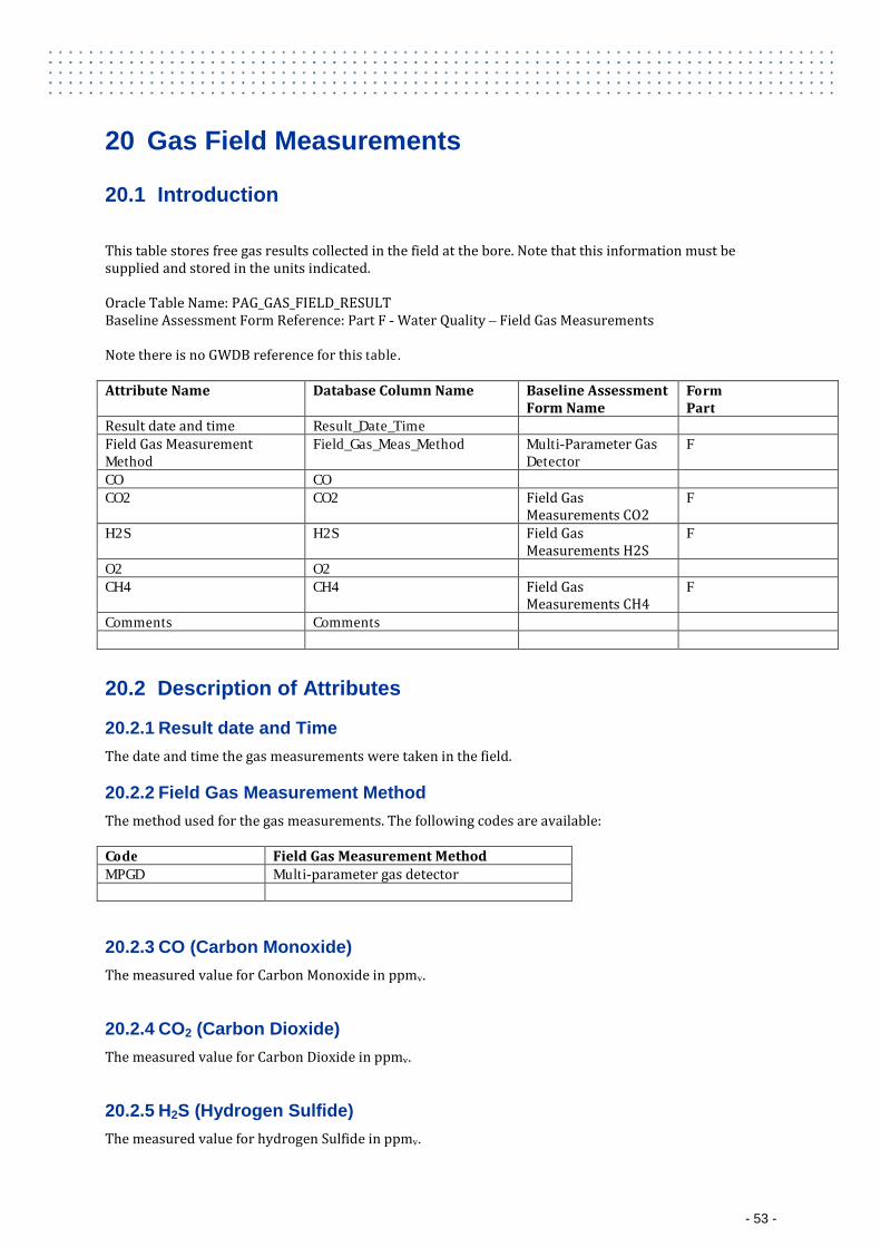
20 Gas Field Measurements
20.1 Introduction
This table stores free gas results collected in the field at the bore. Note that this information must be supplied and stored in the units indicated. Oracle Table Name: PAG_GAS_FIELD_RESULT Baseline Assessment Form Reference: Part F - Water Quality – Field Gas Measurements Note there is no GWDB reference for this table. Attribute Name Database Column Name Baseline Assessment
Form Name Form Part
Result date and time Result_Date_Time Field Gas Measurement Method
Field_Gas_Meas_Method Multi-Parameter Gas Detector
F
CO CO CO2 CO2 Field Gas
Measurements CO2 F
H2S H2S Field Gas Measurements H2S
F
O2 O2 CH4 CH4 Field Gas
Measurements CH4 F
Comments Comments
20.2 Description of Attributes
20.2.1 Result date and Time The date and time the gas measurements were taken in the field.
20.2.2 Field Gas Measurement Method The method used for the gas measurements. The following codes are available: Code Field Gas Measurement Method MPGD Multi-parameter gas detector
20.2.3 CO (Carbon Monoxide) The measured value for Carbon Monoxide in ppmv.
20.2.4 CO2 (Carbon Dioxide) The measured value for Carbon Dioxide in ppmv.
20.2.5 H2S (Hydrogen Sulfide) The measured value for hydrogen Sulfide in ppmv.
- 53 -
20.2.6 O2 (Oxygen) The measured value for oxygen in ppmv.
20.2.7 CH4 (Methane) The measured value for methane in %LEL
20.2.8 Comments Comments relating to Gas readings or gas occurrence at the bore, including any pumping regime prior to assessing the bore that may have impacted on the presence or absence of gas.
- 54 -